FR2764074A1 - METHOD AND DEVICE FOR COOPERATIVE RADIOGONIOMETRY IN TRANSMISSION - Google Patents
METHOD AND DEVICE FOR COOPERATIVE RADIOGONIOMETRY IN TRANSMISSION Download PDFInfo
- Publication number
- FR2764074A1 FR2764074A1 FR9706801A FR9706801A FR2764074A1 FR 2764074 A1 FR2764074 A1 FR 2764074A1 FR 9706801 A FR9706801 A FR 9706801A FR 9706801 A FR9706801 A FR 9706801A FR 2764074 A1 FR2764074 A1 FR 2764074A1
- Authority
- FR
- France
- Prior art keywords
- signal
- vectors
- useful signal
- useful
- interfering
- Prior art date
- Legal status (The legal status is an assumption and is not a legal conclusion. Google has not performed a legal analysis and makes no representation as to the accuracy of the status listed.)
- Granted
Links
Classifications
-
- G—PHYSICS
- G01—MEASURING; TESTING
- G01S—RADIO DIRECTION-FINDING; RADIO NAVIGATION; DETERMINING DISTANCE OR VELOCITY BY USE OF RADIO WAVES; LOCATING OR PRESENCE-DETECTING BY USE OF THE REFLECTION OR RERADIATION OF RADIO WAVES; ANALOGOUS ARRANGEMENTS USING OTHER WAVES
- G01S3/00—Direction-finders for determining the direction from which infrasonic, sonic, ultrasonic, or electromagnetic waves, or particle emission, not having a directional significance, are being received
- G01S3/02—Direction-finders for determining the direction from which infrasonic, sonic, ultrasonic, or electromagnetic waves, or particle emission, not having a directional significance, are being received using radio waves
- G01S3/04—Details
- G01S3/043—Receivers
-
- G—PHYSICS
- G01—MEASURING; TESTING
- G01S—RADIO DIRECTION-FINDING; RADIO NAVIGATION; DETERMINING DISTANCE OR VELOCITY BY USE OF RADIO WAVES; LOCATING OR PRESENCE-DETECTING BY USE OF THE REFLECTION OR RERADIATION OF RADIO WAVES; ANALOGOUS ARRANGEMENTS USING OTHER WAVES
- G01S3/00—Direction-finders for determining the direction from which infrasonic, sonic, ultrasonic, or electromagnetic waves, or particle emission, not having a directional significance, are being received
- G01S3/02—Direction-finders for determining the direction from which infrasonic, sonic, ultrasonic, or electromagnetic waves, or particle emission, not having a directional significance, are being received using radio waves
- G01S3/74—Multi-channel systems specially adapted for direction-finding, i.e. having a single antenna system capable of giving simultaneous indications of the directions of different signals
-
- H—ELECTRICITY
- H04—ELECTRIC COMMUNICATION TECHNIQUE
- H04W—WIRELESS COMMUNICATION NETWORKS
- H04W16/00—Network planning, e.g. coverage or traffic planning tools; Network deployment, e.g. resource partitioning or cells structures
- H04W16/24—Cell structures
Abstract
Description
La présente invention concerne un procédé et un dispositif de radiogoniométrie coopérative en transmission pour des formes d'ondes comportant un signal modulé en modulation linéaire ou pouvant être approximé comme tel, ce signal étant composé de trames comportant des séquences d'apprentissage connues du récepteur et des séquences d'informations utiles. The present invention relates to a method and a device for cooperative direction-finding in transmission for waveforms comprising a signal modulated in linear modulation or which can be approximated as such, this signal being composed of frames comprising training sequences known to the receiver and sequences of useful information.
L'invention peut s'appliquer notamment aux réseaux de communications radiomobiles numériques cellulaires, tels que le GSM,.. The invention can be applied in particular to cellular digital radio mobile communications networks, such as GSM, etc.
Dans un tel contexte, une station de base peut effectuer une goniométrie sur chaque mobile en utilisant les bursts naturellement émis au cours de la communication, pour ensuite émettre de façon directive en direction de chaque mobile, à partir de la connaissance des directions d'arrivée goniométrées. Une telle procédure, basée sur la goniométrie de chacun des mobiles du réseau, permet ainsi de limiter les risques de brouillage envers les autres cellules et donne la possibilité d'introduire le mode SDMA (Spatial
Division Multiple Access), où plusieurs utilisateurs peuvent utiliser la même fréquence au même moment.In such a context, a base station can carry out a direction finding on each mobile using the bursts naturally emitted during the communication, to then transmit in a directive manner towards each mobile, starting from the knowledge of the directions of arrival goniometric. Such a procedure, based on the direction finding of each of the mobiles in the network, thus makes it possible to limit the risks of interference to the other cells and gives the possibility of introducing SDMA mode (Spatial
Division Multiple Access), where multiple users can use the same frequency at the same time.
Actuellement, plusieurs types de méthodes à haute résolution ou super résolution permettent d'effectuer la goniométrie en présence de plusieurs sources. Parmi ces méthodes, il est courant d'utiliser celles connues sous les noms de MUSIC, ESPRIT, Minimum Norm ou Maximum de vraisemblance pour la goniométrie haute résolution, et celle connue sous le nom de CAPON pour la goniométrie à super résolution. Currently, several types of high resolution or super resolution methods allow goniometry to be performed in the presence of several sources. Among these methods, it is common to use those known under the names of MUSIC, ESPRIT, Minimum Norm or Maximum Likelihood for high resolution goniometry, and that known under the name of CAPON for super resolution goniometry.
A titre indicatif, une description de ces méthodes peut être trouvée dans les articles suivants. As a guide, a description of these methods can be found in the following articles.
La méthode MUSIC a été publiée dans l'article intitulé Multiple
Emitter Location and Signal Parameter Estimation de la revue IEEE Trans.The MUSIC method was published in the article entitled Multiple
Emitter Location and Signal Parameter IEEE Trans review estimate.
Ant. Prop., Vol AP-34, n" 3, pp 276-280, March 1986 ayant pour auteur
M. R.D. SCHMIDT.Ant. Prop., Vol AP-34, n "3, pp 276-280, March 1986 whose author is
MRD SCHMIDT.
La méthode ESPRIT est connue de l'article intitulé Estimation of
Signal Parameters via Rotational Invariance Techniques de la revue IEEE
Transaction ASSP, Vol ASSP-37, n" 7, pp 984-995, July 1989 ayant pour auteurs MM. R. ROY, T. KAILATH.The ESPRIT method is known from the article entitled Estimation of
Signal Parameters via Rotational Invariance Techniques of the IEEE review
Transaction ASSP, Vol ASSP-37, n "7, pp 984-995, July 1989 whose authors are Messrs. R. ROY, T. KAILATH.
La méthode Minimum Norm ou Modified FB2B (MFBCP) est connue de l'article intitulé Estimating the Angles of Arrival of Multiple plane raves, de la revue IEEE Trans. Aerosp. Elect-syst., Vol AES-19, n" 1, pp 134-138, January 1983 ayant pour auteurs MM. R. KUMARESAN,
D. W. TUFTS.The Minimum Norm or Modified FB2B (MFBCP) method is known from the article entitled Estimating the Angles of Arrival of Multiple plane raves, from the journal IEEE Trans. Aerosp. Elect-syst., Vol AES-19, n "1, pp 134-138, January 1983 whose authors are Messrs. R. KUMARESAN,
DW TUFTS.
La méthode Maximum de Vraisemblance est connue de l'article intitulé Maximum Likelihood Localizated of Multiple Sources by Alternating Projection de la revue IEEE Trans. ASSP, Vol ASSP-36, n" 10, pp 1553-1560, October 1988 ayant pour auteurs MM. I. ZISKIND, M. WAX. The Maximum Likelihood method is known from the article Maximum Likelihood Localizated of Multiple Sources by Alternating Projection from the journal IEEE Trans. ASSP, Vol ASSP-36, n "10, pp 1553-1560, October 1988 whose authors are Messrs. I. ZISKIND, M. WAX.
La méthode CAPON, MV, MLM est connue de l'article intitulé High Resolution Frequency - Wave number Spectrum Analysais, de la revue IEEE, Vol n" 8, pp 1408-1418, August 1969 ayant pour auteur
M. J. CAPON.The CAPON, MV, MLM method is known from the article entitled High Resolution Frequency - Wave number Spectrum Analyzes, from the journal IEEE, Vol n "8, pp 1408-1418, August 1969, having as author
MJ CAPON.
Néanmoins, ces méthodes sont limitées par le nombre de capteurs du réseau utilisé. Expérimentalement, avec N capteurs, il est possible de séparer N12 trajets arrivant sur le réseau. Or, lorsque plusieurs sources sont présentes, chacune de ces sources peut être associée à plusieurs trajets de propagation:
- réflexions sur les couches ionosphériques pour la gamme de fréquence HF,
- réflexions sur les obstacles (immeubles, collines,...) dans des environnements de type urbain ou montagneux pour les autres gammes de fréquence,
et le nombre de trajets associés à toutes les sources peut devenir trop important pour que la méthode de goniométrie puisse tous les séparer.However, these methods are limited by the number of sensors in the network used. Experimentally, with N sensors, it is possible to separate N12 paths arriving on the network. However, when several sources are present, each of these sources can be associated with several propagation paths:
- reflections on the ionospheric layers for the HF frequency range,
- reflections on obstacles (buildings, hills, ...) in urban or mountainous environments for the other frequency ranges,
and the number of trips associated with all the sources may become too large for the direction finding method to separate them all.
L'invention a pour but d'isoler chacune des sources parvenant sur le réseau, afin que la goniométrie n'ait à traiter que les trajets associés à une seule source. The object of the invention is to isolate each of the sources arriving on the network, so that the direction finding has to process only the paths associated with a single source.
A cet effet, I'invention a pour objet un procédé de radiogoniométrie coopérative en transmission dans un récepteur de radiogoniométrie pour système de radiocommunication comportant plusieurs sources d'émission, le récepteur étant du type comportant un réseau de capteurs couplé à un radiogoniomètre caractérisé en ce qu'il comporte:
- une première étape consistant à numériser le signal reçu par chaque capteur,
- une deuxième étape consistant à effectuer une prise de synchronisation sur les signaux issus de la première étape;
- et une troisième étape consistant, à partir des séquences d'apprentissage insérées dans les formes d'ondes émises par chaque source, à isoler la contribution de chaque source dans les signaux capteurs afin de n'effectuer la goniométrie que sur une seule source.To this end, the subject of the invention is a method of cooperative direction-finding in transmission in a direction-finding receiver for a radiocommunication system comprising several emission sources, the receiver being of the type comprising a network of sensors coupled to a direction-finding device characterized in that it includes:
a first step consisting in digitizing the signal received by each sensor,
a second step consisting in carrying out a synchronization taking on the signals originating from the first step;
- And a third step consisting, from the learning sequences inserted in the waveforms emitted by each source, to isolate the contribution of each source in the sensor signals in order to perform the direction finding on a single source.
Elle a également pour objet un dispositif pour la mise en oeuvre du procédé précité. It also relates to a device for implementing the above method.
Le procédé décrit dans l'invention permet d'améliorer les performances de la goniométrie en présence de plusieurs sources dans un contexte de transmission. Elle a également pour avantage de permettre la localisation des mobiles, pour émettre de façon directive en direction de chaque mobile à partir de la connaissance de la direction d'arrivée des mobiles goniométrés. Elle permet de diminuer la puissance d'émission à portée constante, où à augmenter la portée d'émission à puissance constante et donc de diminuer le brouillage envers les autres cellules. The method described in the invention makes it possible to improve the performance of direction-finding in the presence of several sources in a transmission context. It also has the advantage of allowing the location of the mobiles, to transmit in a directive manner towards each mobile from the knowledge of the direction of arrival of the direction-finding mobiles. It makes it possible to reduce the transmission power at constant range, or to increase the transmission range at constant power and therefore to reduce interference to the other cells.
Comme autre avantage, le procédé selon l'invention permet de connaître à quelle source correspond les trajets goniométrés, ce qui n'est pas le cas avec une goniométrie classique où l'une des difficultés est d'attribuer une source à chaque trajet détecté car les directions d'arrivée associées à une même source peuvent être totalement différentes. As another advantage, the method according to the invention makes it possible to know which source corresponds to the goniometric paths, which is not the case with conventional goniometry where one of the difficulties is to assign a source to each detected path because the directions of arrival associated with the same source can be totally different.
Lorsque la propagation se fait selon un trajet dominant, la méthode de goniométrie mise en oeuvre après l'étape d'isolement de chaque source peut être classique, par formation de voies ou par interférométrie comme cela est décrit par exemple dans l'article intitulé Les techniques d'interférométrie utilisées dans les radiogoniomètres à Thomson-CSF publiée dans la Revue Technique Thomson-CSF, Vol. 19, n" 2, pp 249-287,
Juin 1987.When the propagation takes place along a dominant path, the goniometry method implemented after the step of isolating each source can be conventional, by channel formation or by interferometry as described for example in the article entitled Les interferometry techniques used in Thomson-CSF direction finders published in Thomson-CSF Technical Review, Vol. 19, n "2, pp 249-287,
June 1987.
D'autres caractéristiques et avantages de l'invention apparaîtront dans la description qui suit faite en regard des dessins annexés qui se présentent:
- la figure 1, la composition d'un burst GSM,
- la figure 2, les différentes étapes du procédé de radiogoniométrie coopérative selon l'invention sous la forme d'un organigramme pour illustrer la première méthode,
- la figure 3, un récepteur pour la mise en oeuvre du procédé selon l'invention selon la première méthode,
- la figure 4, les différentes étapes du procédé selon l'invention sous la forme d'un organigramme pour illustrer la deuxième méthode,
- La figure 5, un récepteur pour la mise en oeuvre du procédé de l'invention selon la deuxième méthode.Other characteristics and advantages of the invention will appear in the following description given with reference to the accompanying drawings which appear:
- Figure 1, the composition of a GSM burst,
FIG. 2, the different stages of the cooperative direction-finding method according to the invention in the form of a flow chart to illustrate the first method,
FIG. 3, a receiver for implementing the method according to the invention according to the first method,
FIG. 4, the different steps of the method according to the invention in the form of a flowchart to illustrate the second method,
- Figure 5, a receiver for implementing the method of the invention according to the second method.
Le principe de l'invention est d'effectuer une radiogoniométrie en utilisant les séquences d'apprentissage insérées dans la forme d'onde. Deux méthodes peuvent être mise en oeuvre. The principle of the invention is to perform a direction finding using the learning sequences inserted in the waveform. Two methods can be used.
La première méthode consiste, pour retrancher la contribution d'une source donnée, à effectuer une estimation de canal sur la séquence d'apprentissage associée à cette source. L'estimation de canal permet de retrancher la contribution de cette source sur les signaux capteurs, et d'effectuer la goniométrie en présence d'une source en moins. Si toutes les séquences d'apprentissage sont synchronisées, il est possible, pour chacune des M sources parvenant sur le réseau, de déterminer le signal associé, en retranchant la contribution des M-l autres sources, après avoir effectué une estimation de canal sur ces M-l sources. The first method consists, to subtract the contribution of a given source, to carry out a channel estimation on the training sequence associated with this source. The channel estimation makes it possible to subtract the contribution of this source on the sensor signals, and to perform the direction finding in the presence of one less source. If all the training sequences are synchronized, it is possible, for each of the M sources arriving on the network, to determine the associated signal, by subtracting the contribution of the Ml other sources, after having carried out a channel estimation on these Ml sources .
Une deuxième méthode consiste à calculer les vecteurs contenant l'information spatiale de chacun des trajets associés à la source goniométrée (dite source utile), avec une influence minimale des M-l autres sources. Ces vecteurs sont calculés dans un premier temps à l'aide de la séquence d'apprentissage de la source utile, soit en effectuant une corrélation entre les vecteurs signaux capteurs et la séquence d'apprentissage sur chacune des positions correspondant à la longueur de la réponse impulsionnelle du canal utile, soit en effectuant une estimation de canal utile sur chacun des capteurs. L'analyse de goniométrie est effectuée sur les vecteurs issus de ces corrélations, soit en utilisant les vecteurs obtenus sur les séquences d'apprentissage de plusieurs trames consécutives, soit en intégrant les résultats dans une matrice de corrélation calculée sur les vecteurs obtenus sur plusieurs trames consécutives. Cette méthode est intéressante lorsque les corrélations entre les séquences de référence associés aux différents sources sont faibles, c'est-à-dire typiquement dans le cas des transmissions en mode CDMA (Code Division
Multiple Access). Cependant pour un système tel que le système GSM, cette méthode peut donner des résultats décevants, car la corrélation temporelle entre les séquences d'apprentissage peut être élevée et il vaut mieux dans ce cas utiliser la première méthode.A second method consists in calculating the vectors containing the spatial information of each of the paths associated with the goniometric source (called useful source), with a minimal influence of the Ml other sources. These vectors are first calculated using the learning sequence of the useful source, either by correlating the sensor signal vectors and the learning sequence at each of the positions corresponding to the length of the response. impulse of the useful channel, either by carrying out an estimate of useful channel on each of the sensors. The goniometry analysis is carried out on the vectors resulting from these correlations, either by using the vectors obtained on the training sequences of several consecutive frames, or by integrating the results in a correlation matrix calculated on the vectors obtained on several frames consecutive. This method is advantageous when the correlations between the reference sequences associated with the different sources are weak, that is to say typically in the case of transmissions in CDMA mode (Code Division
Multiple Access). However for a system such as the GSM system, this method can give disappointing results, since the temporal correlation between the training sequences can be high and it is better in this case to use the first method.
Suivant l'une ou l'autre des deux méthodes, lorsque deux émissions parviennent sur le réseau, la goniométrie est réalisée alternativement sur l'une puis sur l'autre émission. Lorsque la goniométrie est réalisée sur une émission, celle-ci est dite signal utile, et l'autre émission est dite signal brouilleur. According to one or the other of the two methods, when two transmissions arrive on the network, the direction-finding is carried out alternately on one then on the other emission. When the direction-finding is carried out on a transmission, this is called useful signal, and the other transmission is called interfering signal.
L'exemple de mise en oeuvre de la première méthode est décrit ci-après dans une application GSM utilisant une modulation GMSK (indice et BT=0,3) avec une période symbole égale à 48/1 3,us. Les symboles transmis sur les canaux de trafic sont constitués, comme le montre la figure 1, en trames de 148 symboles composées chacune de deux séquences Sj, S2 de 3 bits de bourrage disposés à leurs extrémités, d'une séquence d'apprentissage S3 composée de 26 bits connus disposée en milieu de trame et de deux séquences S4, S5 de 58 bits d'information chacune disposées de part et d'autre de la séquence d'apprentissage S3. The example of implementation of the first method is described below in a GSM application using GMSK modulation (index and BT = 0.3) with a symbol period equal to 48/1 3, us. The symbols transmitted on the traffic channels consist, as shown in FIG. 1, in frames of 148 symbols each composed of two sequences Sj, S2 of 3 stuffing bits arranged at their ends, of a training sequence S3 composed of 26 known bits arranged in the middle of the frame and two sequences S4, S5 of 58 bits of information each arranged on either side of the training sequence S3.
La modulation GMSK est une modulation à phase continue qui peut s'exprimer de façon approchée sous la forme d'une modulation linéaire, comme cela est défini dans l'article ayant pour titre a Exact and approximate construction of digital phase modulations by superposition of amplitude modulated pulse (AMP) > publiée dans IEEE Transactions on
Communications Vol. 34 (1986) pp 150-160 ayant pour auteur
P.A. LAURENT.GMSK modulation is a continuous phase modulation which can be expressed roughly in the form of a linear modulation, as defined in the article entitled A Exact and approximate construction of digital phase modulations by superposition of amplitude modulated pulse (AMP)> published in IEEE Transactions on
Communications Vol. 34 (1986) pp 150-160 written by
PA LAURENT.
Dans une modulation GMSK le signal modulé z(t) peut s'écrire sous la forme d'un produit de convolution suivant la relation:

Dans la relation (1) la suite g Sont est celle des symboles transmis,
C0 (t) est la première fonction principale de la modulation GMSK et 6(t) est l'impulsion de Dirac.In a GMSK modulation the modulated signal z (t) can be written in the form of a convolution product according to the relation:
In relation (1) the sequence g Are is that of the symbols transmitted,
C0 (t) is the first main function of the GMSK modulation and 6 (t) is the Dirac pulse.
La suite tint S est utilisée pour effectuer l'estimation de canal. En désignant par dn la suite des bits transmise pour une source donnée, prenant les valeurs a 0 ou a 1 , les données correspondantes d, sont codées différentiellement avant d'être modulées. L'information transmise est constituée par la suite g a, t, calculée à partir de la suite q d, t par les formules suivantes: an = 1 si dn = dn~l et an = -1
Dans la relation (1), les symboles Sn s'écrivent
![]()
The tint sequence S is used to perform the channel estimation. By designating by dn the sequence of bits transmitted for a given source, taking the values a 0 or a 1, the corresponding data d, are differentially coded before being modulated. The transmitted information is constituted by the sequence ga, t, calculated from the sequence qd, t by the following formulas: an = 1 if dn = dn ~ l and an = -1
In relation (1), the symbols Sn are written
![]()
Dans le cadre de l'invention le signal brouilleur z(t) arrive sur le réseau d'antennes de réception formé de K capteurs, après son passage dans le canal de propagation radiomobile. Le signal multicapteur s'écrit:
X(t) = [x1(t),...,x(t)]T = s(t)'G(t) +Xu(t), (3), où
- s(t) est le signal brouilleur,
- G (t) est le canal multicapteurs brouilleur reçu, constitué de la forme d'onde globale émission Co(t), du filtre émission, du canal de propagation et du filtre de réception,
- xj(t) est le signal reçu sur le capteur i,
- Xu(t) est la contribution du signal utile et du bruit de fond qui doit être estimée en retranchant la contribution estimée du signal brouilleur.In the context of the invention the interfering signal z (t) arrives on the receiving antenna array formed by K sensors, after its passage in the radiomobile propagation channel. The multisensor signal is written:
X (t) = [x1 (t), ..., x (t)] T = s (t) 'G (t) + Xu (t), (3), where
- s (t) is the interfering signal,
- G (t) is the received interfering multisensor channel, consisting of the global emission waveform Co (t), the emission filter, the propagation channel and the reception filter,
- xj (t) is the signal received on the sensor i,
- Xu (t) is the contribution of the useful signal and the background noise which must be estimated by subtracting the estimated contribution of the interfering signal.
X(t) peut aussi s'écrire en fonction des symboles transmis:
![]()
![]()
où Ts est la période-symbole. where Ts is the symbol period.
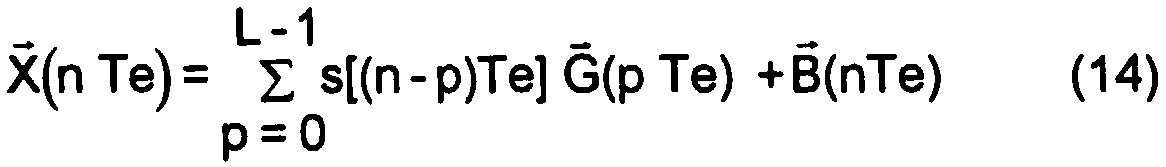
Au cours de la première étape 1 qui est représentée à la figure 2, les signaux reçus sur le réseau d'antennes sont numérisés, transposés en bande de base, puis filtrés par un filtre de réception par tout procédé connu non représenté. Cette étape fournit un signal complexe échantillonné à une fréquence F, multiple de la fréquence symbole Fs. L'étape 2 suivante effectue une synchronisation du récepteur sur le signal complexe obtenu, suivant par exemple le procédé décrit dans la demande de brevet Français n" 2 715 488 déposée au nom de la demanderesse et ayant pour titre procédé de synchronisation en présence de brouilleurs et de multitrajets ou tout autre procédé permettant une synchronisation en présence de brouilleurs et de multitrajets. During the first step 1 which is shown in FIG. 2, the signals received on the antenna array are digitized, transposed into baseband, then filtered by a reception filter by any known method not shown. This step provides a complex signal sampled at a frequency F, multiple of the symbol frequency Fs. The following step 2 performs synchronization of the receiver on the complex signal obtained, for example according to the method described in French patent application no. 2 715 488 filed in the name of the applicant and having as its synchronization method in the presence of jammers and multipaths or any other method allowing synchronization in the presence of jammers and multipaths.
La synchronisation permet de positionner le récepteur de telle sorte que le signal reçu X(nTe) s'exprime en fonction du signal brouilleur émis s(nTe), sl(n - 1)Tel,. . ., sl(n - L + 1)]Te
où L représente la longueur (en nombre d'échantillons) du canal de propagation brouilleur prise en compte lors de l'estimation de canal et Te est la période d'échantillonnage par la relation:

where L represents the length (in number of samples) of the interfering propagation channel taken into account during the channel estimation and Te is the sampling period by the relation:
Les échantillons du signal brouilleur s(nTe) s'expriment lorsque le signal est suréchantillonné d'un facteur 2 par rapport à la fréquence symbole à partir des symboles brouilleur émis par les relations:
s[(2n)Te] = snet s[(2n +1 )Te] = O
Une estimation du canal brouilleur G (t) et de la matrice de corrélation du signal utile plus bruit (Ru) a lieu à l'étape 3. Cette estimation est réalisée suivant trois sous étapes, une sous étape d'estimation du canal brouilleur sur chacune des voies d'entrée, une sous étape d'estimation des échantillons de signal utile plus bruit sur chacune des voies d'entrée et une sous étape d'estimation de la matrice de corrélation du signal utile Ru.The interfering signal samples s (nTe) are expressed when the signal is oversampled by a factor of 2 with respect to the symbol frequency from the interfering symbols emitted by the relations:
s [(2n) Te] = snet s [(2n +1) Te] = O
An estimation of the interfering channel G (t) and of the correlation matrix of the useful signal plus noise (Ru) takes place in step 3. This estimation is carried out according to three sub-steps, a sub-step of estimating the interfering channel on each of the input channels, a sub-step for estimating the useful signal samples plus noise on each of the input channels and a sub-step for estimating the correlation matrix of the useful signal Ru.
L'estimation du canal brouilleur sur chacune des voies d'entrée est effectuée en considérant que le vecteur Gk est constitué à partir des échantillons temporels du canal de propagation brouilleur sur la voie k suivant la relation. The estimation of the interfering channel on each of the input channels is carried out by considering that the vector Gk is constituted from the time samples of the interfering propagation channel on the channel k according to the relation.
Gk = (gk(0),..., gk [(L-1)Te])T. (6)
où gk(t) représente le canal brouilleur obtenu sur la voie k.Gk = (gk (0), ..., gk [(L-1) Te]) T. (6)
where gk (t) represents the interfering channel obtained on channel k.
En notant:
S(nTe) = {s(nTe),..., sl(n - L + 1)Te]}
le vecteur formé à l'aide des symboles brouilleurs connus de la séquence d'apprentissage, le signal reçu par l'antenne k s'écrit:
Xk(n Te) = GHS(n Te)+xu,k(n Te) (7)
où xu,k(n Te) représente les échantillons de signal utile+bruit reçus sur la voie k et où l'opérateur H représente l'opération de transposition-conjugaison. Noting:
S (nTe) = {s (nTe), ..., sl (n - L + 1) Te]}
the vector formed using the interfering symbols known from the training sequence, the signal received by the antenna k is written:
Xk (n Te) = GHS (n Te) + xu, k (n Te) (7)
where xu, k (n Te) represents the useful signal + noise samples received on channel k and where the operator H represents the transposition-conjugation operation.
L'estimation du canal sur la voie k est obtenue par la formule connue de Wiener:
Gk = Rss rsx (8)
où la matrice de corrélation R" et le vecteur d'intercorrélation rSX sont estimés sur les 16 bits placés au centre la séquence d'apprentissage (soit sur N = 32 échantillons lorsque Te = Ts/2) par l'estimateur classique non biaisé suivant les relations:

Gk = Rss rsx (8)
where the correlation matrix R "and the intercorrelation vector rSX are estimated on the 16 bits placed in the center of the training sequence (ie on N = 32 samples when Te = Ts / 2) by the following standard unbiased estimator the relationships:
Dans le système GSM, les séquences de corrélation sont choisies de façon à obtenir une annulation de la fonction d'autocorrélation sur 5 symboles de part et d'autre de t=O. La matrice R" est donc égale à la matrice identité et par suite l'estimation de canal est réalisée directement à partir de rsx alors Gk = rsx
L'estimation des échantillons de signal utile plus bruit sur chacune des voies d'entrée est obtenue à partir de l'estimation du canal de propagation suivant la relation:
xu,k(n Te) = xk(n Te)- GkHS(n Te) (10)
Lorsque le réseau reçoit M brouilleurs dont les séquences d'apprentissage sont synchronisées, sur chaque capteur k, les vecteurs Gk,J du canal de propagation de chaque brouilleur i sont estimés successivement par les formules (8) et (9), et les estimées des échantillons de (signal utile + bruit) sont obtenus par la formule:

The estimation of the useful signal plus noise samples on each of the input channels is obtained from the estimation of the propagation channel according to the relationship:
xu, k (n Te) = xk (n Te) - GkHS (n Te) (10)
When the network receives M jammers whose training sequences are synchronized, on each sensor k, the vectors Gk, J of the propagation channel of each jammer i are estimated successively by the formulas (8) and (9), and the estimated samples of (useful signal + noise) are obtained by the formula:
où Sj(n Te) est le vecteur formé à l'aide des symboles connus de la séquence d'apprentissage du brouilleur i. where Sj (n Te) is the vector formed using the known symbols of the training sequence of the jammer i.
On obtient ainsi une estimée du vecteur signal utile+bruit:
Xu(n Te) = Ku,i(n Te), ...,xu,k(n Te)]T
pour les N échantillons utilisés par l'estimation de canal.
Lorsque la matrice de corrélation du signal utile est requise par la goniométrie, celle-ci s'obtient à partir des échantillons de (signal utile+bruit) estimés Xu(n Te) par l'estimateur classique non biaisé:

Xu (n Te) = Ku, i (n Te), ..., xu, k (n Te)] T
for the N samples used by the channel estimation.
When the correlation matrix of the useful signal is required by the goniometry, this is obtained from the samples of (useful signal + noise) estimated Xu (n Te) by the conventional unbiased estimator:
Afin d'améliorer la qualité de l'estimation de la matrice de corrélation Ru., notamment en présence de fading sélectif en temps, il peut être intéressant d'estimer cette matrice sur plusieurs trames (suffisamment espacées pour obtenir des états de fading différents, mais suffisamment proches pour que les directions d'arrivée à estimer ne varient pas) et de faire la moyenne des estimées ainsi obtenues. La goniométrie du signal utile est effectuée à l'étape 4 à partir de l'estimation de la matrice de corrélation
Ru. Elle peut être réalisée en utilisant tout type de méthode connue que celles-ci, soient à haute résolution, super résolution, formation de voies ou par interférométrie. Pour cette dernière méthode, seule l'estimation des échantillons signal utile + bruit est nécessaire,
Un récepteur pour la mise en oeuvre du procédé selon l'invention est représenté à la figure 3.In order to improve the quality of the estimation of the correlation matrix Ru., In particular in the presence of time-selective fading, it may be advantageous to estimate this matrix on several frames (sufficiently spaced to obtain different fading states, but close enough so that the directions of arrival to be estimated do not vary) and to average the estimates thus obtained. The goniometry of the useful signal is carried out in step 4 from the estimation of the correlation matrix
Ru. It can be carried out using any type of known method, whether these are at high resolution, super resolution, lane formation or by interferometry. For the latter method, only the estimation of the useful signal + noise samples is necessary,
A receiver for implementing the method according to the invention is shown in FIG. 3.
Celui-ci comporte:
- un dispositif 5 de réception du signal reçu sur chaque voie de réception, assorti de façon connue d'un dispositif non représenté pour assurer son passage en bande de base, son filtrage passe bas ainsi que sa numérisation,
- un dispositif 6 de synchronisation du signal sur la séquence de synchronisation associée au brouilleur,
- un dispositif 7 d'estimation du canal associé au signal brouilleur réalisée sur chacune des voies d'entrée,
- un dispositif 8 d'estimation des échantillons de signal utile couplé au dispositif 7 d'estimation du canal brouilleur pour retrancher la contribution du signal brouilleur sur la séquence de synchronisation associée au brouilleur.This includes:
a device 5 for receiving the signal received on each reception channel, combined in a known manner with a device not shown to ensure its passage in baseband, its low pass filtering as well as its digitization,
a device 6 for synchronizing the signal on the synchronization sequence associated with the jammer,
a device 7 for estimating the channel associated with the interfering signal carried out on each of the input channels,
a device 8 for estimating the useful signal samples coupled to the device 7 for estimating the interfering channel to subtract the contribution of the interfering signal on the synchronization sequence associated with the interferer.
- et un radiogoniomètre 9 pour la radiogoniométrie du signal utile couplé à la sortie du dispositif 8 d'estimation de signal utile. Le dispositif d'estimation 8 peut être réalisé à l'aide d'un microprocesseur pour réaliser les traitements de l'étape 3. - And a direction finder 9 for the direction finding of the useful signal coupled to the output of the device 8 for estimating useful signal. The estimation device 8 can be produced using a microprocessor to carry out the processing of step 3.
Le deuxième mode de réalisation de l'invention correspond au cas où les signaux X(t) qui représentent le signal multicapteurs reçu, s'exprime de la façon suivante à partir du signal s(t) formé suivant la formule (1) à partir des symboles émis par le signal utile:
X(t) = [x1(t) , . . , x(t))T = s(t) * G (t) + B(t), où
- G(t) est le canal multicapteur utile reçu, constitué de la forme d'onde globale émission Co(t), du filtre émission, du canal de propagation brouilleur C (t) et du filtre de réception,
- xj(t) est le signal reçu sur le capteur i,
- B(t) est la contribution des signaux brouilleurs et du bruit de fond.The second embodiment of the invention corresponds to the case where the signals X (t) which represent the received multisensor signal, is expressed in the following manner from the signal s (t) formed according to formula (1) from symbols emitted by the useful signal:
X (t) = [x1 (t),. . , x (t)) T = s (t) * G (t) + B (t), where
- G (t) is the useful multisensor channel received, consisting of the global emission waveform Co (t), the emission filter, the interfering propagation channel C (t) and the reception filter,
- xj (t) is the signal received on the sensor i,
- B (t) is the contribution of the interfering signals and the background noise.
X(t) peut aussi s'écrire en fonction des symboles utiles transmis:
![]()
![]()
où Ts est la période-symbole. where Ts is the symbol period.
Le procédé se déroule alors suivant les étapes 10 à 13 de l'organigramme représenté à la figure 4. Il commence à l'étape 10 par la numérisation des signaux reçus et de leur filtrage suivant un processus similaire à celui déjà décrit lors de la première étape du procédé représenté à la figure 2. L'étape 11 suivante est une étape de synchronisation qui permet de positionner le récepteur de telle sorte que le signal reçu X(n Te) s'exprime en fonction du signal utile émis s(nTe), s[(n-1)Te], ..., s[(n-L+1 )Te], où L représente la longueur (en nombre d'échantillons) du canal de propagation utile prise en compte lors de l'estimation de canal et de la goniométrie par la relation:
La goniométrie est effectuée à l'étape 12 après avoir à l'étape 13 estimé des vecteurs contenant l'information spatiale associée aux trajets utiles. The direction-finding is carried out in step 12 after having estimated in step 13 vectors containing the spatial information associated with the useful paths.
Ces vecteurs sont utilisés en effectuant soit une corrélation entre le vecteur contenant les signaux capteurs et le signal utile émis sur la séquence de référence, soit une estimation du canal utile sur chacune des voies d'entrée. These vectors are used by performing either a correlation between the vector containing the sensor signals and the useful signal transmitted on the reference sequence, or an estimate of the useful channel on each of the input channels.
Les vecteurs contenant l'information spatiale associée aux trajets utiles peuvent être obtenus en effectuant une corrélation entre le vecteur contenant les signaux capteurs et le signal utile émis sur la séquence de référence:
L'estimation du canal utile sur chacune des voies d'entrée peut aussi être utilisée pour déterminer les vecteurs contenant l'information spatiale associée aux trajets utiles et a lieu en considérant Gk le vecteur constitué à partir des échantillons temporels du canal de propagation utile sur la voie k:
Gk = (9k( ), ... , gk[(L-1)Te])T (16)
où gk(t) représente le canal utile obtenu sur la voie k.The estimation of the useful channel on each of the input channels can also be used to determine the vectors containing the spatial information associated with the useful paths and takes place by considering Gk the vector formed from the time samples of the useful propagation channel over track k:
Gk = (9k (), ..., gk [(L-1) Te]) T (16)
where gk (t) represents the useful channel obtained on channel k.
En notant: S (n Te) = {s(n Te), ... , s[(n-L+1 )Te]}T le vecteur formé à l'aide des symboles utiles connus de la séquence d'apprentissage, le signal reçu par l'antenne k s'écrit:
xk(n Te) = GFkiS(n Te) + bk(n Te) (17)
L'estimation du canal utile sur la voie k est obtenue par la formule de Wiener utilisée lors de la première méthode pour l'estimation du canal brouilleur (8) (9).By noting: S (n Te) = {s (n Te), ..., s [(n-L + 1) Te]} T the vector formed using the useful symbols known from the learning sequence , the signal received by the antenna k is written:
xk (n Te) = GFkiS (n Te) + bk (n Te) (17)
The estimation of the useful channel on channel k is obtained by the Wiener formula used during the first method for the estimation of the interfering channel (8) (9).
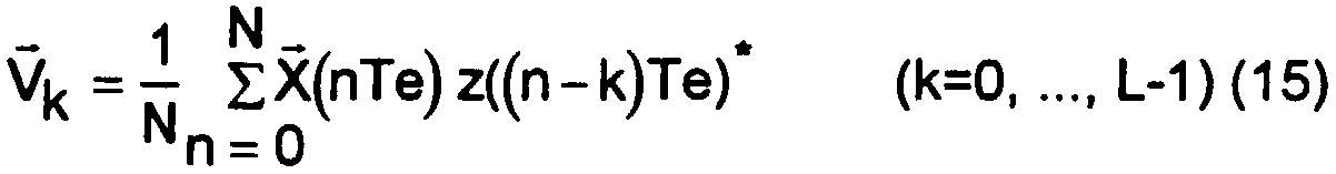
Les L vecteurs V (de dimension K) contenant l'information spatiale sont formés à partir des vecteurs Gk de la façon suivante:
![]()
![]()
A partir de l'estimation des vecteurs contenant l'information spatiale associée au signal utile, la goniométrie du signal utile peut être obtenue suivant quatre possibilités différentes:
Dans un premier cas, une goniométrie est mise en oeuvre pour chaque vecteur V (i = 0,.. ,L-1):
Dans cette configuration, la goniométrie:
- permet de séparer tous les trajets décorrélés, chacun des trajets décorrélés étant associé à un vecteur Vj différent,
- doit séparer les trajets corrélés associés à un même vecteur V. From the estimation of the vectors containing the spatial information associated with the useful signal, the goniometry of the useful signal can be obtained according to four different possibilities:
In a first case, a goniometry is implemented for each vector V (i = 0, .., L-1):
In this configuration, the direction finding:
- makes it possible to separate all the decorrelated paths, each of the decorrelated paths being associated with a different vector Vj,
- must separate the correlated paths associated with the same vector V.
Dans un deuxième cas, une goniométrie est effectuée à partir de la matrice de corrélation R calculée sur les vecteurs Vi obtenus sur une même trame par la relation:
![]()
![]()
Dans cette configuration, la goniométrie doit séparer tous les trajets associés à la source utile, que ceux-ci soient corrélés ou décorrélés. In this configuration, the direction finding must separate all the paths associated with the useful source, whether these are correlated or decorrelated.
Dans un troisième cas, une goniométrie est effectuée pour chaque position i à partir de la matrice de corrélation R, calculée sur les vecteurs Vin déterminés sur N trames (n=1,...N),
![]()
![]()
Dans cette configuration, la goniométrie, de même que dans le premier cas:
- permet de séparer tous les trajets décorrélés, chacun des trajets décorrélés étant associé à un vecteur Vi différent,
- doit séparer les trajets corrélés associés à un même vecteur Vi
L'intérêt d'effectuer la moyenne sur les résultats obtenus sur N trames est d'une part, d'atténuer les effets du fading et d'autre part, de décorréler temporellement (par l'effet Doppler lié au mouvement du véhicule) les trajets associés au même symbole.In this configuration, the direction finding, as in the first case:
- makes it possible to separate all the decorrelated paths, each of the decorrelated paths being associated with a different vector Vi,
- must separate the correlated paths associated with the same vector Vi
The advantage of averaging the results obtained on N frames is on the one hand, to attenuate the effects of fading and on the other hand, to temporally decorrelate (by the Doppler effect linked to the movement of the vehicle) the paths associated with the same symbol.
Dans un quatrième cas, une goniométrie est effectuée à partir de la matrice de corrélation R obtenue en effectuant la moyenne des matrices de corrélation Rj.
![]()
![]()
Dans cette configuration, de même que dans le second cas, la goniométrie doit séparer tous les trajets associés à la source utile, que ceux-ci soient corrélés ou décorrélés. De même que dans le cas précédent, l'intérêt d'effectuer une moyenne des résultats obtenus sur N trames est d'une part, d'atténuer les effets du fading et d'autre part, de décorréler temporellement les trajets associés au même symbole. In this configuration, as in the second case, the direction finding must separate all the paths associated with the useful source, whether these are correlated or decorrelated. As in the previous case, the advantage of performing an average of the results obtained on N frames is on the one hand, to attenuate the effects of fading and on the other hand, to temporally decorrelate the paths associated with the same symbol .
Un récepteur pour la mise en oeuvre du deuxième mode de réalisation de l'invention est représenté à la figure 5. Il comprend un dispositif de réception 14 du signal reçu sur chaque voie de réception, assorti de façon connue par un dispositif, non représenté, pour assurer le passage du signal en bande de base, son filtrage passe bas ainsi que sa numérisation. Un dispositif 15 assure la synchronisation du signal sur la séquence de synchronisation associée au signal utile suivant l'étape 11 du procédé. Un goniomètre 16 couplé en sortie du dispositif de réception 14, assure la goniométrie du signal utile à partir des vecteurs d'information spatiale fournis par un dispositif d'estimation 17 couplé au dispositif de synchronisation 15. La mise en oeuvre du dispositif d'estimation 17 peut être faite à l'aide d'un microprocesseur programmé pour réaliser les traitements de l'étape 13. A receiver for implementing the second embodiment of the invention is shown in FIG. 5. It comprises a device 14 for receiving the signal received on each reception channel, matched in a known manner by a device, not shown, to ensure the passage of the signal in baseband, its low pass filtering as well as its digitization. A device 15 ensures the synchronization of the signal on the synchronization sequence associated with the useful signal according to step 11 of the method. A goniometer 16 coupled to the output of the reception device 14, provides the goniometry of the useful signal from the spatial information vectors supplied by an estimation device 17 coupled to the synchronization device 15. The implementation of the estimation device 17 can be done using a microprocessor programmed to carry out the processing of step 13.
Claims (13)
Priority Applications (6)
| Application Number | Priority Date | Filing Date | Title |
|---|---|---|---|
| FR9706801A FR2764074B1 (en) | 1997-06-03 | 1997-06-03 | TRANSMISSION COOPERATIVE RADIOGONIOMETRY METHOD AND DEVICE |
| PCT/FR1998/001093 WO1998055881A1 (en) | 1997-06-03 | 1998-05-29 | Radiogoniometry method and device co-operating in transmission |
| US09/445,029 US6239746B1 (en) | 1997-06-03 | 1998-05-29 | Radiogoniometry method and device co-operating in transmission |
| EP98928400A EP0991952B1 (en) | 1997-06-03 | 1998-05-29 | Radiogoniometry method and device co-operating in transmission |
| DE69803454T DE69803454T2 (en) | 1997-06-03 | 1998-05-29 | RADIO BEARING METHOD AND INTERACTING TRANSMISSION DEVICE |
| AU80239/98A AU8023998A (en) | 1997-06-03 | 1998-05-29 | Radiogoniometry method and device co-operating in transmission |
Applications Claiming Priority (1)
| Application Number | Priority Date | Filing Date | Title |
|---|---|---|---|
| FR9706801A FR2764074B1 (en) | 1997-06-03 | 1997-06-03 | TRANSMISSION COOPERATIVE RADIOGONIOMETRY METHOD AND DEVICE |
Publications (2)
| Publication Number | Publication Date |
|---|---|
| FR2764074A1 true FR2764074A1 (en) | 1998-12-04 |
| FR2764074B1 FR2764074B1 (en) | 1999-08-20 |
Family
ID=9507524
Family Applications (1)
| Application Number | Title | Priority Date | Filing Date |
|---|---|---|---|
| FR9706801A Expired - Fee Related FR2764074B1 (en) | 1997-06-03 | 1997-06-03 | TRANSMISSION COOPERATIVE RADIOGONIOMETRY METHOD AND DEVICE |
Country Status (6)
| Country | Link |
|---|---|
| US (1) | US6239746B1 (en) |
| EP (1) | EP0991952B1 (en) |
| AU (1) | AU8023998A (en) |
| DE (1) | DE69803454T2 (en) |
| FR (1) | FR2764074B1 (en) |
| WO (1) | WO1998055881A1 (en) |
Cited By (2)
| Publication number | Priority date | Publication date | Assignee | Title |
|---|---|---|---|---|
| FR2829241A1 (en) * | 2001-09-05 | 2003-03-07 | Thales Sa | METHOD AND DEVICE FOR COOPERATIVE RADIOGONIOMETRY IN TRANSMISSION |
| FR2954515A1 (en) * | 2009-12-23 | 2011-06-24 | Thales Sa | METHOD AND DEVICE FOR SIGNAL GONIOMETRY INTERFERING A USEFUL SIGNAL MODULATED BY MULTIPLE CARRIERS. |
Families Citing this family (16)
| Publication number | Priority date | Publication date | Assignee | Title |
|---|---|---|---|---|
| FR2790098B1 (en) | 1999-02-23 | 2001-05-11 | Thomson Csf | METHOD FOR LOCATING TERRESTRIAL MOBILE RADIOS FROM AN AIRCRAFT |
| FR2805614B1 (en) | 2000-02-25 | 2003-08-22 | Thomson Csf | METHOD FOR LOCATING RADIO SOURCES USING A TWO-CHANNEL HIGH RESOLUTION RADIOGONIOMETER |
| FR2806499B1 (en) * | 2000-03-20 | 2003-10-10 | Thomson Csf | METHOD FOR ESTIMATING AN INTERFERENT SIGNAL CORRELATION MATRIX RECEIVED BY A SENSOR ARRAY |
| AU2002211881A1 (en) * | 2000-10-13 | 2002-04-22 | Science Applications International Corporation | System and method for linear prediction |
| FR2819357B1 (en) * | 2001-01-09 | 2016-02-12 | Thomson Csf | AUTODIDACTIVE METHOD AND RECEIVER FOR DETERMINING SPATIO-TEMPORAL PARAMETERS OF A PROPAGATION CHANNEL |
| FR2820580B1 (en) * | 2001-02-02 | 2004-06-04 | Thomson Csf | METHOD FOR ESTIMATING THE PARAMETERS OF A SPREAD CHANNEL |
| FR2821502A1 (en) * | 2001-02-27 | 2002-08-30 | Thomson Csf | METHOD AND DEVICE FOR ESTIMATING A PROPAGATION CHANNEL FROM ITS STATISTICS |
| FR2824146B1 (en) * | 2001-04-27 | 2006-02-24 | Thomson Csf | SYSTEM AND METHOD FOR LOCATING RADIOMOBILES OUTSIDE THE COVERAGE OF A CELLULAR NETWORK |
| FR2824145B1 (en) | 2001-04-27 | 2005-04-15 | Thomson Csf | METHOD AND DEVICE FOR SPATIO-TEMPORAL ESTIMATION OF ONE OR MORE TRANSMITTERS |
| FR2829325B1 (en) * | 2001-09-05 | 2005-06-17 | Thales Sa | METHOD AND DEVICE FOR DETECTING SOURCES IN A COMMUNICATION SYSTEM |
| US8082286B1 (en) | 2002-04-22 | 2011-12-20 | Science Applications International Corporation | Method and system for soft-weighting a reiterative adaptive signal processor |
| US7415065B2 (en) * | 2002-10-25 | 2008-08-19 | Science Applications International Corporation | Adaptive filtering in the presence of multipath |
| FR2854290B1 (en) | 2003-04-25 | 2005-08-26 | Thales Sa | METHOD OF DEMODULATING OFDM-TYPE SIGNALS IN THE PRESENCE OF STRONG CO-CHANNEL BROKERS |
| US7508875B1 (en) * | 2005-09-15 | 2009-03-24 | Bae Systems Information And Electronic Systems Integration Inc. | Correlation matrix estimation via adaptive array perturbational processing to enable jammer location |
| RU2521084C1 (en) * | 2012-09-24 | 2014-06-27 | Общество с ограниченной ответственностью Научно-производственное предприятие "Новые Технологии Телекоммуникаций" | Differential-range method of determining coordinates of radio-frequency source |
| RU2515571C1 (en) * | 2012-10-05 | 2014-05-10 | Федеральное государственное образовательное учреждение высшего профессионального образования "Санкт-Петербургский государственный университет телекоммуникаций им. проф. М.А. Бонч-Бруевича" | Method of determining coordinates of target in three-position ranging radar system |
Citations (4)
| Publication number | Priority date | Publication date | Assignee | Title |
|---|---|---|---|---|
| US4728959A (en) * | 1986-08-08 | 1988-03-01 | Ventana Sciences Inc. | Direction finding localization system |
| WO1996014588A1 (en) * | 1994-11-03 | 1996-05-17 | Muloc Inc. | Communications localization system |
| DE19511752A1 (en) * | 1995-03-30 | 1996-10-10 | Siemens Ag | Process for high-resolution evaluation of signals for one- or two-dimensional direction or frequency estimation |
| JPH09119970A (en) * | 1995-10-24 | 1997-05-06 | Mitsubishi Electric Corp | Communication and position-measuring device |
Family Cites Families (3)
| Publication number | Priority date | Publication date | Assignee | Title |
|---|---|---|---|---|
| FR2715488B1 (en) | 1994-01-21 | 1996-03-22 | Thomson Csf | Method and device enabling a modem to synchronize with a digital data transmitter over the air in the presence of jammers. |
| FR2732490B1 (en) | 1995-03-28 | 1997-04-25 | Thomson Csf | MULTI-SENSOR RECEPTION PROCESS FOR A BASE STATION OF A COMMUNICATION NETWORK EXCHANGING DATA WITH MOBILES, AND DEVICE FOR ITS IMPLEMENTATION |
| US5870430A (en) | 1996-12-26 | 1999-02-09 | Thomson-Csf | Process for multi-sensor equalisation in a radio receiver in the presence of interference and multiple propagation paths |
-
1997
- 1997-06-03 FR FR9706801A patent/FR2764074B1/en not_active Expired - Fee Related
-
1998
- 1998-05-29 EP EP98928400A patent/EP0991952B1/en not_active Expired - Lifetime
- 1998-05-29 DE DE69803454T patent/DE69803454T2/en not_active Expired - Lifetime
- 1998-05-29 AU AU80239/98A patent/AU8023998A/en not_active Abandoned
- 1998-05-29 WO PCT/FR1998/001093 patent/WO1998055881A1/en active IP Right Grant
- 1998-05-29 US US09/445,029 patent/US6239746B1/en not_active Expired - Lifetime
Patent Citations (4)
| Publication number | Priority date | Publication date | Assignee | Title |
|---|---|---|---|---|
| US4728959A (en) * | 1986-08-08 | 1988-03-01 | Ventana Sciences Inc. | Direction finding localization system |
| WO1996014588A1 (en) * | 1994-11-03 | 1996-05-17 | Muloc Inc. | Communications localization system |
| DE19511752A1 (en) * | 1995-03-30 | 1996-10-10 | Siemens Ag | Process for high-resolution evaluation of signals for one- or two-dimensional direction or frequency estimation |
| JPH09119970A (en) * | 1995-10-24 | 1997-05-06 | Mitsubishi Electric Corp | Communication and position-measuring device |
Non-Patent Citations (2)
| Title |
|---|
| DATABASE WPI Section EI Week 9728, Derwent World Patents Index; Class W01, AN 97-307581 * |
| PATENT ABSTRACTS OF JAPAN vol. 097, no. 009 30 September 1997 (1997-09-30) * |
Cited By (5)
| Publication number | Priority date | Publication date | Assignee | Title |
|---|---|---|---|---|
| FR2829241A1 (en) * | 2001-09-05 | 2003-03-07 | Thales Sa | METHOD AND DEVICE FOR COOPERATIVE RADIOGONIOMETRY IN TRANSMISSION |
| EP1291664A1 (en) | 2001-09-05 | 2003-03-12 | Thales | Method and system for cooperative radio direction finding in transmission mode |
| US6693591B2 (en) | 2001-09-05 | 2004-02-17 | Thales | Method and device for co-operative radio direction-finding in transmission |
| FR2954515A1 (en) * | 2009-12-23 | 2011-06-24 | Thales Sa | METHOD AND DEVICE FOR SIGNAL GONIOMETRY INTERFERING A USEFUL SIGNAL MODULATED BY MULTIPLE CARRIERS. |
| WO2011076864A1 (en) * | 2009-12-23 | 2011-06-30 | Thales | Method and device for goniometry of signals interfering with a useful signal modulated by plurality of carriers |
Also Published As
| Publication number | Publication date |
|---|---|
| DE69803454T2 (en) | 2002-08-08 |
| AU8023998A (en) | 1998-12-21 |
| FR2764074B1 (en) | 1999-08-20 |
| EP0991952B1 (en) | 2002-01-09 |
| US6239746B1 (en) | 2001-05-29 |
| DE69803454D1 (en) | 2002-02-28 |
| EP0991952A1 (en) | 2000-04-12 |
| WO1998055881A1 (en) | 1998-12-10 |
Similar Documents
| Publication | Publication Date | Title |
|---|---|---|
| EP0991952B1 (en) | Radiogoniometry method and device co-operating in transmission | |
| EP0931429B1 (en) | Method and device for analysing interference in a cellular radiocommunication system | |
| EP0702866B1 (en) | Signaling packet for communication system with modulated reference according to a time-base law | |
| CA2172672C (en) | Process and device for carying out a multisensor reception at a fixed base station of a communication network exchanging data with mobile stations | |
| EP0858181A1 (en) | Method for diversity equalisation in a radio receiver having a predetermined number of receiving channels and corresponding receiver | |
| CA2400763A1 (en) | Method for locating radioelectric sources using two-channel high resolution radiogoniometer | |
| EP1288674A1 (en) | Method and device of speed estimation of a mobile terminal of a wireless communication system | |
| EP0926510A1 (en) | Method of position determination of mobiles in an urban environment | |
| EP1050973A1 (en) | Method for joint detection of a CDMA code set | |
| EP1305921A1 (en) | Method for processing a digital input signal of a channel equalizer | |
| EP1260071B1 (en) | Method and device for estimating channel propagation | |
| EP1291664B1 (en) | Method and system for cooperative radio direction finding in transmission mode | |
| FR2882479A1 (en) | Rectilinear signal e.g. amplitude modulation signal, synchronization method for e.g. identification friend foe system, involves defining decision criterion by taking into account non circular character of interferences of second order | |
| EP1235399B1 (en) | Method and apparatus to estimate the covariance matrix of the transmission channel of a UMTS system | |
| FR2798794A1 (en) | METHOD FOR PROCESSING MULTI-PATH NAVIGATION SIGNALS IN A RECEIVER HAVING A PLURALITY OF ANTENNAS | |
| EP0708544A1 (en) | Apparatus for recognizing information carried by a received signal | |
| EP1229696A1 (en) | Channel parameters estimation using maximum likelihood estimation | |
| EP1296460A1 (en) | Method and apparatus for determining the fading coefficients of a multipath transmission channel connecting in particular a base station and a mobile telephone | |
| EP1240759B1 (en) | Device for estimating radio channel and demodulation | |
| EP1292047B1 (en) | Method and apparatus for detecting sources in a communication system | |
| FR3040574A1 (en) | METHOD AND DEVICE FOR MIMO SYNCHRONIZATION IN THE PRESENCE OF INTERFERENCE | |
| FR2735635A1 (en) | Multiple sensor spatial and temporal equalisation method for radio receiver | |
| FR2819963A1 (en) | PARTICULATE RECEPTOR FOR THE OPTIMAL JOINT ESTIMATION OF DIGITAL AND CONTINUOUS INFORMATION IN PULSED MODULATION SIGNALS |
Legal Events
| Date | Code | Title | Description |
|---|---|---|---|
| CD | Change of name or company name | ||
| ST | Notification of lapse |