EP0931429B1 - Method and device for analysing interference in a cellular radiocommunication system - Google Patents
Method and device for analysing interference in a cellular radiocommunication system Download PDFInfo
- Publication number
- EP0931429B1 EP0931429B1 EP98937617A EP98937617A EP0931429B1 EP 0931429 B1 EP0931429 B1 EP 0931429B1 EP 98937617 A EP98937617 A EP 98937617A EP 98937617 A EP98937617 A EP 98937617A EP 0931429 B1 EP0931429 B1 EP 0931429B1
- Authority
- EP
- European Patent Office
- Prior art keywords
- frequency
- beacon
- frequencies
- traffic
- synchronization
- Prior art date
- Legal status (The legal status is an assumption and is not a legal conclusion. Google has not performed a legal analysis and makes no representation as to the accuracy of the status listed.)
- Expired - Lifetime
Links
Images


Classifications
-
- H—ELECTRICITY
- H04—ELECTRIC COMMUNICATION TECHNIQUE
- H04W—WIRELESS COMMUNICATION NETWORKS
- H04W16/00—Network planning, e.g. coverage or traffic planning tools; Network deployment, e.g. resource partitioning or cells structures
- H04W16/18—Network planning tools
Definitions
- the present invention relates to a method and a device for interference analysis in a radiocommunication system cell type GSM or DCS 1800 for example.
- a macrocell puts in work a base station placed on a high point like the roof of a building and its radius can reach several kilometers.
- a microcell serves areas of smaller radius a few hundred meters. It implements a basic ministry whose aerial is located generally below the roof of buildings, on poles lighting, for example.
- Software tooling allows the operator to plan the implementation base stations and their characteristics according to the population subscribers to serve.
- Material tools are transported on vehicles. he has a trace function for storing measurements performed on the network.
- the interference problem main take place on the downlink between base station and mobile because base stations are usually placed on high points ideal for transmitting signals at long distances.
- the engineering of the network generally provides for a "tilt”, ie an inclination of antennas so, to force the radiation from the base station to no cover only the territory inside his cell. But this "tilt” is not always sufficient to prevent inadvertent radiation to adjacent cells that are causing interference between broadcasts different base stations.
- the problem is then for the operator to identify the source interference detected in neighboring cells. This detection is usually done with relatively few trace mobiles sophisticated equipment whose equipment is similar to that fitted to mobiles usual communication skills. These trace mobiles provide the operator the information used by the usual mobiles to qualify a communication ie information RX LEVEL and RX QUAL. This information, the method of obtaining of which is described in GSM standard allow to qualify the signal level received (RX LEVEL) as well as the quality of communication (RX QUAL). In these conditions an interference situation is detected when the level of the received signal is strong while the quality of the communication is declared bad. The problem for the operator is then to identify the jammer while the mobile trace provides no identifier or marking.
- planning software tools are unable to take local peculiarities such as an opening in a row of buildings that promotes unwanted radiation.
- the MATHAUER V document entitled: ⁇ Optimum funkzellen criticism ' nachlet electronik und telematik>, vol. 46, No. 6, June 1, 1992, page 317/318, 320 XP000471604 describes a system allowing an optimal planning of cellular networks. For this, the system sends a signal to simulate a base station BTS, in order to choose the best position.
- the object of the invention is to overcome the aforementioned disadvantages in proposing a solution for the reliable determination of interferences between traffic that does not have intrinsic markers.
- the invention also relates to a device for the implementation of the aforementioned method.
- the architecture of the GSM system which is represented in the figure 1 makes it possible to provide digital communications between mobiles and subscribers of the public switched network.
- a series of functions are required. These functions are those required by any mobile network. These include numbering function, the routing function to a user mobile, cell transfer function etc.
- These functions are grouped into functional entities represented schematically in Figures 1 and 2. They are composed of mobile phones, BSS radio subsystems and management sub-systems and NSS routing.
- the MS, BSS and NSS references are respectively the English abbreviations for "Mobile station”, “Base Station System", and "Network and Switching Sub-System".
- mobile station physical equipment that is used by a user who travels through cells of a network. This mobile station allows the user to access the services of telecommunication offered. Different types of mobile stations exist, they differ according to whether they are mounted on vehicles, or that they have the form of portable or portable devices.
- a radio subsystem is equipment that provides the coverage of a specific geographical area, called a cell. he contains the hardware and software needed to communicate with mobile stations. Functionally a radio subsystem ensures a control function using a BSC base station controller and a radio transmission function supported by base stations BTS.
- BSC and BTS are the abbreviations Anglo-Saxon for "Base Station Controller” and "Base Transceiver Station”.
- the territory of each cell is covered using a base station. It manages the links with MS mobile stations using a interface called "radio interface”.
- the relations between the stations of BTS base and their base station controller are defined by a interface called “Abis interface”. Base station controllers are connected to the rest of the network using an interface called "Interface AT ".
- An NSS management and routing subsystem is consists of three elements hereinafter referred to as MSC, HLR, and VLR.
- MSC element is a mobile service switch responsible for routing of communications from and to mobiles in a cell.
- HLR element is a database where are registered the permanent parameters of a subscriber; it also contains for each mobile information to locate it. This information is updated permanently.
- VLR element is a database where is recorded a fine localization of the mobile in call area.
- the structure of the network is cellular, its capacity is obtained in garrisoning the territory by means of cells each served by a station basic.
- GSM Global System for Mobile communications
- the number of cells juxtaposed using the same frequencies is indicated by a pattern of reuse.
- the cellular network planning example in Figure 3 is that of a network where the reuse pattern has a size of 4. On finds that the frequency of cell # 3 is reused at a low distance and that interference may occur between the cells.
- the device according to the invention which is represented in FIG. identify in a cell the interference caused by neighboring cells.
- This device comprises an antenna array 1 coupled to a multi-channel receiver 2 allowing the synchronous reception of the signals received by each of the antennas.
- Digital processing equipment 3 coupled to the multi-channel receiver 2 allows the scanning of signals provided by the receiver 2 and to ensure through a console 4 the interface with a user.
- a storage interface 5 coupled with the digital processing equipment 3 ensures the storage of Detected Items.
- the digital processing equipment 3 detects the type of frequency channel on which is positioned the reception system and performs a classification between beacon and traffic frequencies. he determines, on a beacon-type channel, the BSIC identification word which is the English abbreviation "Base Station Identification Color" of each cell "Best server” and interfering cells, obtained after demodulation of SCH bursts as well as the CI identity of each cell and its location code LAC, after demodulation of BCCH bursts.
- beacon frequency the frequency of traffic and the demodule to provide the list of traffic frequencies associated; if the list matches the traffic frequency detected, the beacon frequency is decoded to provide the identity Cl, and the LAC location code.
- the synchronism between beacon frequency and traffic frequency corresponds to a temporal concordance in the emission of the bursts on the two frequencies.
- the antenna array 1 can be constituted by way of example, antennas known as GSM / DCS1800 arranged on the the roof of a vehicle, ensuring that the distance between elements is at least equal to 0.5 times the longest wavelength ⁇ used in order to obtain fading states for each emission independent on each sensor. Geometric distribution matters little and the number of antennas employed may be variable, however the number 5 is a good balance between performance and complexity of treatment. Examples of antenna implantation are shown in Figures 5 and 6.
- functions of the device can be supplemented by a function of GPS positioning to correlate the scrambling assumptions with network planning and the location of the measurement, and a function of teleoperation and telemetry, in order to have autonomous equipment on the place of measurement.
- the identification of the base stations challenged by a interference phenomenon takes place according to steps 6 to 21 of the process represented in the flowchart of Figure 7.
- This process allows to perform for each selected channel on the one hand, the search for base stations using this channel as beacon frequency, with a decoding type 3 messages to obtain the identity of the CI cell and the code of its location LAC and secondly, search stations using this channel as the traffic frequency, as well as the search for the associated beacon frequency by identifying it thanks synchronism of bursts transmitted on beacon and traffic frequencies by the same base station.
- This identification takes place taking into account the specificities of the GSM system, namely that it provides for two types of channel frequencies associated with each base station, a frequency channel of beacon and traffic frequency channels.
- the beacon frequency channel (only one per station) allows the base station to broadcast to the mobiles served by the cell a certain number of signaling information not dedicated to a communication or to a mobile. It also serves as a frequency reference for mobile and is issued at a constant level even if it is not traffic information because a constant level of mobile devices to perform quick identification. It also carries specific bursts (SCH bursts) allowing synchronization time and the identification of reference sequences (TSC) that are used for signaling bursts.
- SCH bursts specific bursts
- TSC reference sequences
- Traffic frequency channels are all other channels Frequencies used, they mainly carry traffic bursts (burst TCH) and present energy only when a communication is conveyed on the TCH bursts.
- burst TCH traffic bursts
- step 8 a multichannel synchronization of SCH burst on a sequence of 64-bit long reference as shown in Figure 8. This sequence has sufficient autocorrelation performance that make it easy to identify reported interference situations by several synchronization peaks. These bursts are present on the time interval TNO of the multiframe 51 of the beacon frequency, as shown in Figure 9.
- the FCH bursts marked with the letter F are bursts unmodulated which correspond to a carrier and which allow mobile devices to perform rapid detection of beacon frequencies.
- the BCCH bursts marked with the letter B are signaling bursts general, to all mobiles carrying the signaling and which contain the identification information of the cells (CI) and localization (LAC).
- the PAGCCH bursts spotted by the letter P are mobile call bursts. These last two types of bursts are like the TCH bursts of traffic bursts that carry the voice.
- the process continues at step 10 of the flowchart of the Figure 7, performing a multi-channel demodulation of SCH bursts identified in FIG. 9 by the letter S, in order to extract the code identification of BSIC stations.
- the BSIC code contains two information. A first information indicates the PLMN number of the network and a second information indicates the reference sequence. TSC that will be used by the base station on the bursts of signaling. This second piece of information is coded the way represented in FIG. 10.
- the coding implements a cyclic code for the generation of a CRC error correcting code and a code convolutional to improve demodulation performance.
- the interest of decode the BSIC code is that it allows the identification of base stations in the presence. A consultation of a planning database allows then to isolate the stations presenting the same emissions of beacon frequency and the same BSIC code.
- a second type of information that identifies the stations in presence is the CI information which is the abbreviation of "Cell identity”.
- This information is transmitted by base stations on beacon frequency using BCCH bursts. These bursts aim to convey system signaling messages including the type 3 message which contains the identification information Cl and LAI, LAI being the abbreviation of "Location Area Identification” which makes it possible to identify a group of cells in which is broadcast a call.
- the type 3 message is cyclically transmitted on the Beacon frequency at a rate of two times per two second cycle. This gives the possibility to the device to store at least one second signal and thus have at least one recurrence of type 3 message.
- the CI and LAI information is coded according to the Figure 11. This coding consists in spreading the message over the 4 bursts BCCH of multiframe 51 from block interleaving resulting from a convolutive encoding of the type 3 message to which is attached an error correction CRC code.
- Steps 14 and 15 are preliminary steps that consist of first to perform at step 14 a multi-channel synchronization on the TCH bursts before performing their detection in step 15. Only 3 Types of waveform bursts shown in Figure 8 are used. They concern FCH bursts, SCH bursts and traffic bursts. All bursts BCCH, PAGCH, etc. are actually bursts with the same physical structure as the TCH bursts and which consist of a sequence of 26 framed symbols of two data areas of 58 useful symbols.
- synchronization step 14 is performed by successively performing a test of each of the possible sequences and providing the position of the bursts detected as well as the detected sequences.
- Steps 16 to 21 in Figure 7 are intended to identify the base station transmitting the disruptive traffic frequency.
- the method performs in step 16 a temporal marking of the arrival interfering traffic bursts, and position the system on another frequency in step 17. On this frequency, it will look at step 18, SCH bursts respecting a TDMA rhythm consistent with that indicated by the time stamping of step 16.
- Step 19 allows you to perform the detection: if it finds a SCH burst that respects the TDMA rhythm, then the process goes to step 20, otherwise it goes back to step 17 to change frequency.
- Step 20 makes it possible to perform the demodulation of the synchronous beacon frequency of the traffic frequency and provide among the signaling messages the list of traffic frequencies used by the cell that has this beacon frequency.
- Step 21 allows to compare this list to the frequency of interfering traffic. In case concordance, the interfering cell is found and the method provides its CI identification and its BSIC code, by decoding the SCH bursts of the beacon frequency.
- This algorithm takes into account the prediction that can be performed on the position of the secondary peaks and on their level.
- the processing starts in step 22 by detecting TCH bursts, followed in step 23 by sorting the detected bursts by sorting them into a list in descending order of their estimated signal to noise ratio SNIR.
- step 22 locating the position of the reference sequences is performed and the SNIR corresponding to each position is estimated.
- Step 24 makes it possible to initialize the filtering process by positioning a pointer N on the first position in the list.
- step 25 The purpose of step 25 is to select the current TSC, the SNIR current and current position of the selected item in the list by the pointer N.
- Step 26 makes it possible to position a second pointer K in the same position as the first pointer.
- Step 27 allows move the second pointer K to the next position in the list.
- Step 28 makes it possible to address an ambiguity table with as input the TSCs used by the elements of the list pointed by the two pointers N and K. This table determines the list of deviations ambiguity in time possible for the two selected TSCs, as well as for each ambiguity gap, the associated SNIR.
- TSC i the eight training sequences
- the positions ⁇ p for which the threshold has been exceeded at least once.
- the average value of the synchronization criterion is calculated when the threshold is exceeded, as well as the percentage of cases where the threshold has been exceeded.
- the results are stored in the ambiguity table, exploited by the sorting algorithm, which takes these values into account in order to decide that a sequence TSC i detected on a position p should not be retained since it corresponds in fact to a sequence TSC i transmitted on the position p + ⁇ p.
- Step 29 compares the measured difference for the two elements of the list with the list of possible time differences for ambiguity TSC. If a concordance exists the process continues in step 30, otherwise it goes to the execution of step 27 to position the second pointer K on the next item in the list.
- Step 30 is optional. She makes a comparison between the SNIRs of the ambiguity table and those detected. concordance exists, the process continues in step 31, if not it returns to step 27 to position the second pointer K on another item in the list.
- Step 31 eliminates the element pointed by K.
- Step 32 checks if there are any items in the list to go through the pointer K, if yes the process returns to step 27 to increment the pointer K. Otherwise it continues at step 33 to increment the N pointer
- Step 34 completes the process by checking if there are any remaining items in the list to increment the N pointer. If so, then the process returns to step 25. Otherwise the process is complete.
- This algorithm can, however, be optimized in the case of a traffic jamming on a beacon frequency.
- the positions of the traffic bursts on the beacon frequency are known from the positions of bursts SCH.
- the positions of the bursts TCH of a beacon frequency being perfectly known these, do not should not be filtered by the sort algorithm. This is what is represented on the flowchart in Figure 15, or the positions corresponding to these bursts are at the top of the list and are not questioned in the filtering.
- Treatment begins at step 35 by locating the bursts SCH, the determination of the BSIC (which provides the TSC sequence of the bursts BCCH), and the determination of SNIR signal-to-noise ratios correspondents. This is a list of M positions that were not questioned.
- steps 22 and 23 identical to those of Fig. 14, which provide another list.
- assistants in step 37 taking care to place the M elements previous ones at the top of the list, and eliminate redundancies.
- the filtering process can then start, as specified in figure 15. It is identical to that of figure 14, except at the stage 38 which does not allow to position the pointer K at the top of the list (only after the Mth item in the list).
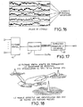
- FIG. 17 A device for carrying out the method is shown in FIG. 17.
- This device comprises a spatial filtering device 42 coupled to a message extraction and decoding device 43.
- the execution of the first step of the method consisting of to detect the presence of SCH bursts on a beacon channel or the presence of TCH bursts on a traffic channel can be implemented according to the synchronization technique described in the French patent application No. FR 2715488 filed in the name of the Applicant entitled "Method and device for a modem to synchronize on a digital data transmitter over the air in the presence of jammers. This technique allows a modem to synchronize using learning sequences inserted into the waveform.
- this technique makes it possible to detect the presence of a burst of SCH or TCH type on a sample p of signal as a function of the value of a multichannel synchronization criterion C (p) defined by the relation: with:
- the synchronization is placed at the moment of appearance of a sample (p) of signal when the value C (p) of the criterion is greater than a determined threshold value ⁇ .
- This SNIR is used during step 30 of the sorting algorithm of TCH bursts.
- the implementation of multi-channel synchronization therefore requires, for each position p tested, the computation of r and Xd (p), of R and XX (p) of the inverse of R and XX (p) and of the criterion r and Xd (p) R and -1 XX (p). r and Xd (p).
- the matrix R and XX (p) is calculated and inverted for all P positions, ie for the positions p 0 such that p modulo P is zero, in performing the correlation on N + P samples:
- the criterion C (p) is calculated using R and -1 XX (p 0 ), the calculation of r and Xd (p) remaining unchanged.
- the detected synchronization positions provide the starting information necessary for the demodulation.
- the demodulation is obtained according to two stages, a filtering stage by the device 42 and a single-channel equalization step by the 44.
- Spatial filtering makes it possible, on the one hand, to eliminate interference on the same or adjacent channel and on the other hand, to obtain a gain of diversity that is obtained by spreading enough sensors to each other to receive independent fading states.
- Spatial filtering can be implemented either by using a known method of spatial filtering on replica simple (FAS-R) that leads to separate the different multipath associated with a given emission, either by using a spatial filtering method filtered replication (FAS-RF) which allows for it to take into account all of these multipaths.
- FAS-RF spatial filtering method filtered replication
- Spatial filtering and equalization are implemented in the invention by exploiting the SCH training sequences for the demodulation of SCH bursts or TSC training sequences for the demodulation of BCCH bursts.
- the filtered overhead filtering method is described in the French patent application No. FR 2742619 filed in the name of the Applicant entitled: "Multi-sensor equalization process allowing multi-sensor reception in the presence of interference and multipath propagation, and receiver for its implementation "and for inventors MM. Institut PIPON, Pierre VILA and Didier PIREZ.
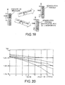
- FIG. 21 One embodiment of the equalizing device 44 is shown in FIG. 21.
- This includes a computing device 45 coupled to a replica 42 spatial filtering device via of a matched filter 46 and a channel estimation device 48.
- computing device 45 performs the one-dimensional equalization of the signals at the output of the spatial filtering for each of the detected sources.
- a signal processing processor 47 suitably programmed according to the known Viterbi algorithm coupled on the one hand, to the spatial filter 42 through the adapted filter 46 and on the other on the other hand, to a channel estimation device 48 through a calculation of the coefficients ⁇ 49 necessary for the execution of the algorithm of Viterbi.
- a calculation device for estimating the signal-to-noise ratio 50 is also coupled at the output of the computing device 49 and at the output of the channel estimation device 48.
- the processor 47 determines the transmitted symbol sequence that minimizes the probability of error of decision.
- One-dimensional equalization can also be performed by other types of algorithms, less complex numerically as the Viterbi algorithm, which are used for a single-sensor reception as the one known as "Algorithm" which is a simplified version of the Viterbi algorithm or even the DFE equalizer, although these EQs lead to slightly degraded results compared to those obtained with the algorithm from Viterbi. However, they can be used for applications or the available computing power is insufficient to implement this latest.
- (d n ) denotes the sequence of transmitted bits, taking values '0' or '1' and it is assumed that the data d n are differentially coded before being modulated.
- the modulation GMSK is a modulation to continuous phase that can express itself in an approximate way in the form linear modulation as described in the article by M. P.A. LAURENT, with the title: “Exact and approximate construction of digital phase modulation by superposition of amplitude modulated pulse (AMP) ", IEE Trans., Comm Flight 34 (1986) pp. 150-160.
- AMP amplitude modulated pulse
- the demodulation consists in determining the sequence (s n ) and then going up again following the transmitted bits (d n ).
- X (t) can also be written according to the symbols transmitted according to the relation: where Ts is the symbol period.
- the processor 47 determines the transmitted symbol sequence. It is programmed according to the Viterbi algorithm, a description of which can be found in the article by MJG PROAKIS, entitled "Adaptive Equalization for TDMA Digital Mobile Radio", IEEE Trans. On Vehicular Techn., vol 40, n ° 2, May 1991.
- This algorithm makes it possible, from a sequence of symbols (y n ) obtained at the output of the matched filter 46, to find the sequence (s k0 n ) of index k 0 which minimizes the probability of decision error on the transmitted sequence of symbols, or in an equivalent manner that maximizes the following criterion:
- the Viterbi algorithm works from the output signal y n of the matched filter 46 and the coefficients ⁇ n obtained at the output of the computing device 49.
- This calculation is performed by the computing device 48 which applies this result on an input of the device for calculating the signal-to-noise ratio 50.
- the factor 2n is due to the fact that the coefficients used by the Viterbi algorithm are calculated at the symbol rate).
- the signal-to-noise ratio at the output of the spatial filter 42 is equal to the coefficient ⁇ 0 .
- This noise is in first approximation only composed of background noise, since the interference formed by other emissions are rejected.
- the coefficient ⁇ 0 therefore constitutes an estimate of the signal-to-noise ratio at the output of the spatial filter.
- the first two phenomena can be taken into account by a calibration by injecting a known level signal at the input of receivers and comparing the estimated level in dBm at the actually injected.
Description
La présente invention concerne un procédé et un dispositif pour l'analyse des interférences dans un système de radiocommunication cellulaire de type GSM ou DCS 1800 par exemple.The present invention relates to a method and a device for interference analysis in a radiocommunication system cell type GSM or DCS 1800 for example.
Dans un système de radiocommunication cellulaire la couverture d'un territoire déterminé a lieu en utilisant des cellules desservies par des stations de base et en appliquant un motif de réutilisation des fréquences, qui permet d'augmenter la capacité du réseau.In a cellular radio system the coverage of a specified territory takes place using cells served by base stations and applying a pattern of frequency reuse, which increases the capacity of the network.
Différents types de cellules sont utilisés. Ceux-ci sont constitués de macrocellules et de microcellules. Une macrocellule met en oeuvre une station de base placée sur un point élevé comme le toit d'un immeuble et son rayon peut atteindre plusieurs kilomètres. Une microcellule dessert des zones de plus faible rayon de quelques centaines de mètres. Elle met en oeuvre une ministation de base dont l'aérien est situé généralement en dessous du toit des bâtiments, sur des poteaux d'éclairage par exemple.Different types of cells are used. These are consisting of macrocells and microcells. A macrocell puts in work a base station placed on a high point like the roof of a building and its radius can reach several kilometers. A microcell serves areas of smaller radius a few hundred meters. It implements a basic ministry whose aerial is located generally below the roof of buildings, on poles lighting, for example.
Dans ces systèmes la réutilisation importante des fréquences, en particulier dans des zones de forte densité d'abonnés, fait apparaítre des interférences importantes en co-canal et sur des canaux adjacents. Une planification du réseau est donc nécessaire pour éliminer ces interférences. Cette planification est réalisée par un opérateur qui dispose d'un certain nombre d'outils logiciels et matériels lui permettant d'apprécier la conformité entre la population d'abonnés à desservir et la capacité du réseau mis en place.In these systems the significant reuse of frequencies, particularly in areas of high subscriber density, significant interference in co-channel and on adjacent channels. Network planning is therefore necessary to eliminate these interference. This planning is carried out by an operator who has a number of software and hardware tools that allow it to to assess the conformity between the subscriber population to be served and the network capacity set up.
L'outillage logiciel permet à l'opérateur de prévoir l'implantation des stations de base et leur caractéristiques en fonction de la population d'abonnés à desservir.Software tooling allows the operator to plan the implementation base stations and their characteristics according to the population subscribers to serve.
L'outillage matériel est transporté sur des véhicules. Il comporte une fonction de trace permettant le stockage de mesures effectuées sur le réseau.Material tools are transported on vehicles. he has a trace function for storing measurements performed on the network.
Dans le cadre d'un réseau GSM, le problème d'interférences principal a lieu sur la liaison descendante entre station de base et mobile car les stations de base sont généralement placées sur des points hauts idéaux pour l'émission de signaux à de longues distances. L'ingénierie du réseau prévoit généralement un « tilt », c'est à dire une inclinaison des antennes afin,de forcer le rayonnement de la station de base à ne recouvrir que le territoire intérieur à sa cellule. Mais ce « tilt »n'est pas toujours suffisant pour éviter des rayonnements intempestifs vers des cellules adjacentes qui sont la cause d'interférences entre les émissions des différentes stations de base.In the context of a GSM network, the interference problem main take place on the downlink between base station and mobile because base stations are usually placed on high points ideal for transmitting signals at long distances. The engineering of the network generally provides for a "tilt", ie an inclination of antennas so, to force the radiation from the base station to no cover only the territory inside his cell. But this "tilt" is not always sufficient to prevent inadvertent radiation to adjacent cells that are causing interference between broadcasts different base stations.
Le problème est alors pour l'opérateur d'identifier la provenance des interférences détectées dans les cellules voisines. Cette détection s'effectue ordinairement à l'aide de mobiles de trace relativement peu sophistiqués dont l'équipement est similaire de celui équipant les mobiles de communication habituels. Ces mobiles de trace fournissent à l'opérateur les informations utilisées par les mobiles habituels pour qualifier une communication c'est à dire les informations RX LEVEL et RX QUAL. Ces informations, dont le mode d'obtention est décrit dans la norme GSM permettent de qualifier le niveau de signal reçu (RX LEVEL) ainsi que la qualité de la communication (RX QUAL). Dans ces conditions une situation d'interférence est détectée lorsque le niveau du signal reçu est fort alors que la qualité de la communication est déclarée mauvaise. Le problème pour l'opérateur est alors d'identifier le brouilleur alors que le mobile de trace n'en fournit aucun identifiant ou marquant.The problem is then for the operator to identify the source interference detected in neighboring cells. This detection is usually done with relatively few trace mobiles sophisticated equipment whose equipment is similar to that fitted to mobiles usual communication skills. These trace mobiles provide the operator the information used by the usual mobiles to qualify a communication ie information RX LEVEL and RX QUAL. This information, the method of obtaining of which is described in GSM standard allow to qualify the signal level received (RX LEVEL) as well as the quality of communication (RX QUAL). In these conditions an interference situation is detected when the level of the received signal is strong while the quality of the communication is declared bad. The problem for the operator is then to identify the jammer while the mobile trace provides no identifier or marking.
En outre, les outils logiciels de planification sont incapables de prendre des particularités locales comme par exemple une ouverture dans une rangée d'immeubles qui favorise des rayonnements indésirables.In addition, planning software tools are unable to take local peculiarities such as an opening in a row of buildings that promotes unwanted radiation.
La procédure suivie par l'opérateur fait largement appel à son expérience. Elle consiste, par déduction à l'aide de la base de données de planification, à identifier la station perturbatrice en la déconnectant momentanément du réseau afin de vérifier l'amélioration de la qualité des communications. Cependant ces opérations restent contraignantes car d'une part, elles demandent une très bonne expérience terrain à la personne chargée d'effectuer l'analyse et d'autre part, la déconnexion des stations de base suspectes conduit à une dégradation du service. En outre, dans une configuration très urbanisée comme c'est par exemple le cas dans une ville comme Paris où le déploiement microcellulaire est considérable, l'analyse basée sur l'expérience n'est pratiquement plus envisageable.The procedure followed by the operator makes extensive use of his experience. It consists, by deduction using the database of planning, to identify the disturbing station by disconnecting it momentarily of the network in order to verify the improvement of the quality of the communications. However, these operations remain constraining because on the one hand, they require very good field experience at the person responsible for performing the analysis and secondly, the disconnection suspicious base stations leads to degradation of service. In Moreover, in a very urbanized configuration as it is for example the case in a city like Paris where microcellular deployment is considerable, experience-based analysis is virtually no longer possible.
Le document de MATHAUER V intitulé : <Optimale funkzellenplanung' nachrichten electronik und telematik>, vol. 46, n° 6, 1er juin 1992, page 317/318, 320 XP000471604 décrit un système permettant une planification optimale des réseaux cellulaires. Pour cela, le système envoie un signal permettant de simuler une station de base BTS, afin de choisir la position la meilleure.The MATHAUER V document entitled: <Optimum funkzellenplanung ' nachrichten electronik und telematik>, vol. 46, No. 6, June 1, 1992, page 317/318, 320 XP000471604 describes a system allowing an optimal planning of cellular networks. For this, the system sends a signal to simulate a base station BTS, in order to choose the best position.
Le but de l'invention est de pallier les inconvénients précités en proposant une solution de détermination fiable d'interférences entre fréquences de trafic qui ne disposent pas intrinsèquement de marquants.The object of the invention is to overcome the aforementioned disadvantages in proposing a solution for the reliable determination of interferences between traffic that does not have intrinsic markers.
A cet effet, l'invention a pour objet, un procédé d'analyse des interférences dans un système de radiocommunication cellulaire comportant des fréquences de balise et des fréquences de trafic caractérisé en ce qu'il consiste pour rechercher sur une fréquence d'analyse déterminée et à l'intérieur d'une cellule la provenance d'interférences causées par des cellules voisines,
- à effectuer une synchronisation multivoies sur les séquences d'apprentissage des fréquences de balise pour déterminer le nombre de stations de base utilisant la fréquence d'analyse comme fréquence de balise,
- à démoduler après filtrage spatial les identifiants des stations de base émettrices des fréquences de balise sur lesquelles une synchronisation a été prise,
- à effectuer une synchronisation multivoies sur les séquences d'apprentissage des fréquences de trafic pour déterminer le nombre de stations de base utilisant la fréquence d'analyse comme fréquence de trafic.
- performing multi-channel synchronization on beacon frequency training sequences to determine the number of base stations using the analysis frequency as a beacon frequency,
- demodulating, after spatial filtering, the identifiers of the base stations transmitting the beacon frequencies on which synchronization has been taken,
- performing multi-channel synchronization on the training sequences of the traffic frequencies to determine the number of base stations using the analysis frequency as the traffic frequency.
L'invention a également pour objet un dispositif pour la mise en oeuvre du procédé précité.The invention also relates to a device for the implementation of the aforementioned method.
D'autres caractéristiques et avantages de l'invention apparaítront dans la description qui suit faite en regard des dessins annexés qui représentent :
- La figure 1, un exemple d'architecture connue d'un système GSM,
- La figure 2, la structure d'un réseau GSM,
- La figure 3, un mode de réutilisation de fréquences,
- La figure 4, un mode de réalisation fonctionnel d'un dispositif d'analyse d'interférences selon l'invention,
- Les figures 5 et 6 des modes d'implantation de réseaux d'antennes du dispositif représenté à la figure 4,
- La figure 7 un algorithme d'identification de stations de base sous la forme d'un organigramme,
- La figure 8, des formats des bursts de données FCH, SCH, et de trafic du système GSM,
- La figure 9, la structure de la multi-trame 51 de la fréquence balise du système GSM,
- La figure 10, le mode de codage d'un premier niveau d'identification émis sur les bursts de type SCH du système GSM,
- La figure 11, le mode de codage d'un deuxième niveau d'identification permettant d'identifier l'identité de la cellule qui est transmise par une station de base sur la fréquence de balise à l'aide des bursts BCCH.
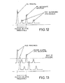
- La figure 12, un exemple de résultats d'intercorrélation effectuées sur les séquences de référence des bursts de trafic du système GSM pour le tri des bursts TCH,
- La figure 13, une illustration d'un cas de fausse alarme produites par les pics secondaires obtenus en résultat de l'intercorrélation des séquences de référence,
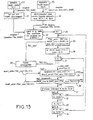
- La figure 14, une représentation sous la forme d'un organigramme d'un algorithme de tri principal des bursts TCH pour éliminer les fausses alarmes,
- La figure 15, un algorithme de tri préliminaire des bursts TCH sous la forme d'un organigramme
- La figure 16, un graphe de diversité spatiale obtenue en sortie des capteurs du système antennaire du dispositif de la figure 4,
- La figure 17, un schéma de principe simplifié d'un démodulateur mis en oeuvre pour la réalisation d'un dispositif selon l'invention,
- La figure 18, un schéma pour illustrer le principe de fonctionnement d'un filtrage spatial mis en oeuvre dans le dispositif selon l'invention,
- Les figures 19 et 20, des diagrammes montrant des performances en anti-brouillage qui peuvent être obtenues par la mise en oeuvre du procédé selon l'invention,
- La figure 21, une structure d'égaliseur pouvant être mis en oeuvre pour la réalisation du dispositif selon l'invention.
- La figure 22, un schéma illustrant le test des ambiguités de synchronisation entre séquences TSC.
- La figure 23, un deuxieme mode de réalisation fonctionnel d'un dispositif d'analyse d'interférences selon l'invention.
- FIG. 1, an example of a known architecture of a GSM system,
- FIG. 2, the structure of a GSM network,
- FIG. 3, a frequency reuse mode,
- FIG. 4, a functional embodiment of an interference analysis device according to the invention,
- FIGS. 5 and 6 of the antenna network implementation modes of the device represented in FIG. 4,
- FIG. 7 an algorithm for identifying base stations in the form of a flowchart,
- FIG. 8, formats of the FCH, SCH, and GSM traffic bursts,
- FIG. 9, the structure of the multi-frame 51 of the beacon frequency of the GSM system,
- FIG. 10, the coding mode of a first identification level transmitted on the SCH type bursts of the GSM system,
- FIG. 11, the coding mode of a second identification level making it possible to identify the identity of the cell that is transmitted by a base station on the beacon frequency using the BCCH bursts.
- FIG. 12, an example of intercorrelation results performed on the reference sequences of GSM system traffic bursts for sorting TCH bursts,
- FIG. 13, an illustration of a false alarm case produced by the secondary peaks obtained as a result of the intercorrelation of the reference sequences,
- FIG. 14, a representation in the form of a flowchart of a main sorting algorithm of the TCH bursts for eliminating false alarms,
- Figure 15, a prescreening algorithm for TCH bursts in the form of a flowchart
- FIG. 16, a graph of spatial diversity obtained at the output of the sensors of the antenna system of the device of FIG. 4,
- FIG. 17, a simplified block diagram of a demodulator implemented for the realization of a device according to the invention,
- FIG. 18, a diagram for illustrating the operating principle of a spatial filtering implemented in the device according to the invention,
- FIGS. 19 and 20, diagrams showing anti-jamming performances that can be obtained by implementing the method according to the invention,
- Figure 21, an equalizer structure that can be implemented for the realization of the device according to the invention.
- FIG. 22, a diagram illustrating the test of synchronization ambiguities between TSC sequences.
- FIG. 23, a second functional embodiment of an interference analysis device according to the invention.
L'architecture du système GSM qui est représentée à la figure 1 permet d'assurer des communications numériques entre des mobiles et des abonnés du réseau public commuté. Pour que le système puisse offrir ces services, une série de fonctions sont nécessaires. Ces fonctions sont celles requises par tout réseau de mobiles. Ce sont notamment la fonction de numérotation, la fonction d'acheminement vers un usager mobile, la fonction de transfert de cellules etc. Ces fonctions sont regroupées dans des entités fonctionnelles représentées schématiquement aux figures 1 et 2. Elles sont composées de stations mobiles MS, de sous systèmes radio BSS et de sous systèmes de gestion et d'acheminement NSS. Les références MS, BSS et NSS sont respectivement les abréviations anglo-saxonnes pour « Mobile station », « Base Station System », et « Network and Switching Sub-System ».The architecture of the GSM system which is represented in the figure 1 makes it possible to provide digital communications between mobiles and subscribers of the public switched network. For the system to offer these services a series of functions are required. These functions are those required by any mobile network. These include numbering function, the routing function to a user mobile, cell transfer function etc. These functions are grouped into functional entities represented schematically in Figures 1 and 2. They are composed of mobile phones, BSS radio subsystems and management sub-systems and NSS routing. The MS, BSS and NSS references are respectively the English abbreviations for "Mobile station", "Base Station System", and "Network and Switching Sub-System".
Par station mobile il faut entendre un équipement physique qui est utilisé par un usager qui se déplace au travers de cellules d'un réseau. Cette station mobile permet à l'usager d'accéder aux services de télécommunication offerts. Différents types de stations mobiles existent, elles se différencient suivant qu'elles sont montées sur des véhicules, ou qu'elles ont la forme d'appareils portables ou portatifs.By mobile station is meant physical equipment that is used by a user who travels through cells of a network. This mobile station allows the user to access the services of telecommunication offered. Different types of mobile stations exist, they differ according to whether they are mounted on vehicles, or that they have the form of portable or portable devices.
Un sous-système radio est un équipement qui assure la couverture d'une zone géographique déterminée, appelée cellule. Il contient les matériels et les logiciels nécessaires pour communiquer avec les stations mobiles. Au plan fonctionnel un sous système radio assure une fonction de contrôle à l'aide d'un contrôleur de stations de base BSC et une fonction de transmission radio supportée par des stations de base BTS. Les appellations BSC et BTS sont les abréviations anglo-saxonnes pour « Base Station Controller » et « Base Transceiver Station ». Le territoire de chaque cellule est couvert à l'aide d'une station de base. Celle-ci gère les liaisons avec les stations mobiles MS à l'aide d'une interface appelée « radio interface ». Les relations entre les stations de base BTS et leur contrôleur de stations de base sont définies par une interface dénommée « interface Abis ». Les contrôleurs de station de base sont reliés au reste du réseau à l'aide d'une interface appelée « Interface A ».A radio subsystem is equipment that provides the coverage of a specific geographical area, called a cell. he contains the hardware and software needed to communicate with mobile stations. Functionally a radio subsystem ensures a control function using a BSC base station controller and a radio transmission function supported by base stations BTS. The names BSC and BTS are the abbreviations Anglo-Saxon for "Base Station Controller" and "Base Transceiver Station". The territory of each cell is covered using a base station. It manages the links with MS mobile stations using a interface called "radio interface". The relations between the stations of BTS base and their base station controller are defined by a interface called "Abis interface". Base station controllers are connected to the rest of the network using an interface called "Interface AT ".
Un sous-système de gestion et d'acheminement NSS se compose de trois éléments dénommés ci-après MSC, HLR, et VLR. L'élément MSC est un commutateur de service mobile chargé de l'acheminement des communications à partir de et vers les mobiles dans une cellule. L'élément HLR est une base de données où sont enregistrés les paramètres permanents d'un abonné ; il contient par ailleurs pour chaque mobile une information permettant de le localiser. Cette information est mise à jour de façon permanente. L'élément VLR est une base de données où est enregistrée une localisation fine du mobile en zone d'appel.An NSS management and routing subsystem is consists of three elements hereinafter referred to as MSC, HLR, and VLR. The MSC element is a mobile service switch responsible for routing of communications from and to mobiles in a cell. The HLR element is a database where are registered the permanent parameters of a subscriber; it also contains for each mobile information to locate it. This information is updated permanently. The VLR element is a database where is recorded a fine localization of the mobile in call area.
La structure du réseau est cellulaire, sa capacité est obtenue en maillant le territoire à l'aide de cellules desservies chacune par une station de base.The structure of the network is cellular, its capacity is obtained in garrisoning the territory by means of cells each served by a station basic.
Une caractéristique importante d'un réseau GSM est la
réutilisation des fréquences à travers le réseau. Le nombre de cellules
juxtaposées utilisant les mêmes fréquences est indiqué par un motif de
réutilisation. L'exemple de planification du réseau cellulaire de la figure 3
est celui d'un réseau où le motif de réutilisation a une taille de 4. On
constate que la fréquence de la cellule n°3 est réutilisée à une faible
distance et que des interférences peuvent survenir entre les cellules.An important feature of a GSM network is the
reuse of frequencies across the network. The number of cells
juxtaposed using the same frequencies is indicated by a pattern of
reuse. The cellular network planning example in Figure 3
is that of a network where the reuse pattern has a size of 4. On
finds that the frequency of
Le dispositif selon l'invention qui est représenté à la figure 4
permet d'identifier dans une cellule les interférences causées par des
cellules voisines. Ce dispositif comprend un réseau d'antennes 1 couplé à
un récepteur multivoies 2 permettant la réception synchrone des signaux
reçus par chacune des antennes. Un équipement de traitement numérique
3 couplé au récepteur multivoie 2 permet d'effectuer la numérisation des
signaux fournis par le récepteur 2 et d'assurer par l'intermédiaire d'une
console 4 l'interface avec un utilisateur. Une interface de stockage 5
couplée à l'équipement de traitement numérique 3 assure le stockage des
éléments détectés. The device according to the invention which is represented in FIG.
identify in a cell the interference caused by
neighboring cells. This device comprises an
L'équipement de traitement numérique 3 détecte le type de
canal fréquentiel sur lequel est positionné le système de réception et
effectue une classification entre fréquences de balise et de trafic. Il
détermine, sur un canal de type balise, le mot d'identification BSIC qui
est l'abréviation anglo-saxonne « Base Station Identification Colour », de
chaque cellule « Best server »et des cellules interférentes, obtenu après
démodulation de bursts SCH ainsi que l'identité CI de chaque cellule et
son code de localisation LAC, après démodulation des bursts BCCH.
Enfin, sur un canal de type trafic il détermine la liste des séquences de
référence TSC détectées sur le canal, ainsi que des niveaux de réception
associés, recherche une fréquence de balise synchrone de la fréquence de
trafic et la démodule afin de fournir la liste des fréquences de trafic
associées ; en cas de concordance entre la liste et la fréquence de trafic
détectées, la fréquence de balise est décodée pour fournir l'identité Cl, et
le code de localisation LAC. Le synchronisme entre fréquence de balise et
fréquence de trafic correspond à une concordance temporelle dans
l'émission des bursts sur les deux fréquences.The
Le réseau d'antennes 1 peut être constitué à titre d'exemple,
d'antennes connues sous la désignation GSM/DCS1800 disposées sur le
pavillon d'un véhicule en s'assurant que l'écartement entre chaque
éléments est au moins égal à 0,5 fois la plus grande longueur d'onde λ
utilisée de façon à obtenir pour chaque émission des états de fading
indépendants sur chaque capteur. La répartition géométrique importe peu
et le nombre d'antennes employé peut être variable, cependant le chiffre
5 correspond à un bon équilibre entre performances et complexité de
traitement. Des exemples d'implantation d'antennes sont montrés aux
figures 5 et 6.The
Afin d'offrir une souplesse d'utilisation et d'exploitation, les fonctions du dispositif peuvent être complétées par une fonction de positionnement de type GPS afin de corréler les hypothèses de brouillage avec la planification du réseau et le lieu de la mesure, et une fonction de téléopération et de télémesure, afin d'avoir un équipement autonome sur le lieu de la mesure.In order to offer flexibility of use and exploitation, functions of the device can be supplemented by a function of GPS positioning to correlate the scrambling assumptions with network planning and the location of the measurement, and a function of teleoperation and telemetry, in order to have autonomous equipment on the place of measurement.
L'identification des stations de base mises en cause par un
phénomène d'interférence a lieu suivant les étapes 6 à 21 du procédé
représenté sur l'organigramme de la figure 7. Ce procédé permet
d'effectuer pour chaque canal sélectionné d'une part, la recherche des
stations de base utilisant ce canal comme fréquence de balise, avec un
décodage des messages de type 3 pour obtenir l'identité de la cellule CI
et le code de sa localisation LAC et d'autre part, la recherche des stations
de base utilisant ce canal comme fréquence de trafic, ainsi que la
recherche de la fréquence de balise associée en identifiant celle-ci grâce
au synchronisme des bursts émis sur les fréquences de balise et de trafic
par une même station de base.The identification of the base stations challenged by a
interference phenomenon takes place according to
Cette identification a lieu en tenant compte des spécificités du système GSM, à savoir qu'il prévoit deux types d'utilisation des canaux fréquentiels associés à chaque station de base, un canal fréquentiel de balise et des canaux fréquentiels de trafic.This identification takes place taking into account the specificities of the GSM system, namely that it provides for two types of channel frequencies associated with each base station, a frequency channel of beacon and traffic frequency channels.
Le canal fréquentiel de balise (un seul par station) permet à la station de base de diffuser aux mobiles desservis par la cellule un certain nombre d'informations de signalisation non dédiées à une communication ou à un mobile. Il sert également de référence fréquentielle pour les mobiles et est émis à un niveau constant même s'il n'est pas porteur d'information de trafic car une émission à un niveau constant permet aux mobiles d'effectuer une identification rapide. Il véhicule également des bursts spécifiques (bursts SCH) permettant une synchronisation temporelle et l'identification des séquences de référence (TSC) qui sont utilisées pour les bursts de signalisation.The beacon frequency channel (only one per station) allows the base station to broadcast to the mobiles served by the cell a certain number of signaling information not dedicated to a communication or to a mobile. It also serves as a frequency reference for mobile and is issued at a constant level even if it is not traffic information because a constant level of mobile devices to perform quick identification. It also carries specific bursts (SCH bursts) allowing synchronization time and the identification of reference sequences (TSC) that are used for signaling bursts.
Les canaux fréquentiels de trafic sont tous les autres canaux fréquentiels utilisés, ils véhiculent principalement des bursts de trafic (burst TCH) et présentent de l'énergie uniquement lorsqu'une communication est véhiculée sur les bursts TCH.Traffic frequency channels are all other channels Frequencies used, they mainly carry traffic bursts (burst TCH) and present energy only when a communication is conveyed on the TCH bursts.
Suivant l'organigramme de la figure 7 lorsque le dispositif est
positionné à l'étape 6 sur une fréquence qu'il doit analyser, sa première
tâche est d'identifier à quels types de canal fréquentiel il est confronté. Si
un canal de balise est présent sur le canal analysé l'identification est
aisée et se fait sur l'identifiant CI de la cellule émettrice alors que dans le
cas d'un canal de trafic cet identifiant n'existe pas hormis par le biais de
la séquence TSC utilisée. Pour ce faire, le dispositif effectue à l'étape 8
une synchronisation multivoies de burst SCH sur une séquence de
référence longue de 64 bits comme indiqué sur la figure 8. Cette
séquence présente des performances d'autocorrélation suffisantes qui
permettent d'identifier aisément des situations d'interférences signalés
par plusieurs pics de synchronisation. Ces bursts sont présents sur
l'intervalle temporel TNO de la multitrame 51 de la fréquence de balise,
comme indiqué sur la figure 9. Sur cette figure sont également
représentés par leur première lettre, les emplacements des bursts FCH,
BCCH et PAGCH. Les bursts FCH repérés par la lettre F sont des bursts
non modulés qui correspondent à une porteuse et qui permettent aux
mobiles d'effectuer une détection rapide des fréquences de balise. Les
bursts BCCH repérés par la lettre B sont des bursts de signalisation
générale, à destination de tous les mobiles qui transportent la
signalisation et qui contiennent les informations d'identification des
cellules (CI) et de localisation (LAC). Les bursts PAGCCH repérés par la
lettre P sont des bursts d'appels de mobiles. Ces deux derniers types de
bursts sont comme les bursts TCH des bursts de trafic qui véhiculent la
phonie.Following the flowchart in Figure 7 when the device is
positioned in
Le procédé continue à l'étape 10 de l'organigramme de la
figure 7, en effectuant une démodulation multivoies des bursts SCH
repérés sur la figure 9 par la lettre S, afin d'extraire le code
d'identification des stations BSIC. Le code BSIC contient deux
informations. Une première information indique le numéro PLMN du
réseau et une deuxième information indique la séquence de référence.
TSC qui va être utilisée par la station de base sur les bursts de
signalisation. Cette deuxième information est codée de la manière
représentée à la figure 10. Le codage met en oeuvre un code cyclique
pour la génération d'un code correcteur d'erreur CRC ainsi qu'un code
convolutif pour améliorer les performances de démodulation. L'intérêt de
décoder le code BSIC est qu'il permet l'identification des stations de base
en présence. Une consultation d'une base de donnée de planification
permet ensuite d'isoler les stations présentant les mêmes émissions de
fréquence balise et le même code BSIC.The process continues at
Un deuxième type d'information qui permet d'identifier les
stations en présence est l'information CI qui est l'abréviation anglaise de
« cell identity ».Cette information est transmise par les stations de base
sur la fréquence balise à l'aide des bursts BCCH. Ces bursts ont pour but
de véhiculer des messages de signalisation système notamment le
message de type 3 qui contient les informations d'identification Cl et LAI,
LAI étant l'abréviation anglo-saxonne de « Location Area Identification »
qui permet d'identifier un groupement de cellules dans lequel est diffusé
un appel. Le message de type 3 est émis de manière cyclique sur la
fréquence de balise au rythme de deux fois par cycle de deux secondes.
Ceci donne la possibilité au dispositif de stocker au minimum une
seconde de signal et de disposer ainsi d'au moins une récurrence du
message de type 3. Les informations CI et LAI sont codées suivant le
schéma de la figure 11. Ce codage consiste à répartir le message sur les
4 bursts BCCH de la multitrame 51 à partir d'un entrelacement de bloc
résultant d'un codage convolutif du message de type 3 auquel est adjoint
un code CRC correcteur d'erreur.A second type of information that identifies the
stations in presence is the CI information which is the abbreviation of
"Cell identity". This information is transmitted by base stations
on beacon frequency using BCCH bursts. These bursts aim
to convey system signaling messages including the
L'identification des séquences de référence utilisées sur les
canaux a lieu par l'exécution des étapes 14 à16 de l'organigramme de la
figure 7. Les étapes 14 et 15 sont des étapes préliminaires qui consistent
à effectuer d'abord à l'étape 14 une synchronisation multivoies sur les
bursts TCH avant d'effectuer leur détection à l'étape 15. Seulement 3
types de forme d'ondes bursts représentés à la figure 8 sont utilisés.
Elles concernent les bursts FCH, les bursts SCH et les bursts de trafic.
Tous les bursts BCCH, PAGCH, etc. sont en fait des bursts disposant de
la même structure physique que les bursts TCH et qui consistent en une
séquence de 26 symboles encadrés de deux zones de données de 58
symboles utiles. En fait la norme GSM prévoit l'utilisation de 8 différentes
séquences de référence encore appelées en anglais TSC « Training
Séquence code » qui permettent une séparation des communications
utilisant la même fréquence. En conséquence, la synchronisation
multivoies de l'étape 14 a lieu en effectuant successivement un test de
chacune des séquences possibles et en fournissant la position des bursts
détectés ainsi que les séquences détectées.The identification of the reference sequences used on the
channels takes place by performing
Les étapes 16 à 21 de la figure 7 ont pour but d'identifier la
station de base émettrice de la fréquence de trafic perturbatrice. Pour
cela, le procédé effectue à l'étape 16 un marquage temporel de l'arrivée
des bursts de trafic perturbateurs, et positionne le système sur une autre
fréquence à l'étape 17. Sur cette fréquence, il va rechercher à l'étape 18,
des bursts SCH respectant un rythme TDMA cohérent avec celui indiqué
par le marquage temporel de l'étape 16. L'étape 19 permet d'effectuer la
détection : si elle trouve un burst SCH qui respecte le rythme TDMA,
alors le procédé passe à l'étape 20, sinon il revient à l'étape 17 pour
changer de fréquence. L'étape 20 permet de réaliser la démodulation de
la fréquence de balise synchrone de la fréquence de trafic et de fournir
parmi les messages de signalisation la liste des fréquences de trafic
utilisées par la cellule qui possède cette fréquence de balise. L'étape 21
permet de comparer cette liste à la fréquence de trafic brouilleuse. En cas
de concordance, le cellule brouilleuse est trouvée et le procédé fournit
son identification CI et son code BSIC, en décodant les bursts SCH de la
fréquence de balise.
Afin de faciliter le marquage temporel de l'arrivée des bursts de trafic brouilleur et afin d'éviter les dérives d'horloge trop importantes, il est possible d'utiliser une structure de dispositif tel que représenté sur la figure 23, où l'on trouve :
- le même réseau d'antenne 1 que sur la figure 4,
- un diviseur 39 (N vers 2N) qui permet de diviser le signal reçu sur chaque antenne,
- deux
récepteurs 2 qui sont positionnés, l'un sur la fréquence brouilleuse et l'autre qui recherche la fréquence de balise associée, - un équipement numérique 40 permet de numérisé deux fois
plus de signaux que l'équipement 3 de la figure 4 et qui
permet d'effectuer une recherche de bursts TCH en
permanence sur le signal recu par le premier récepteur et une
recherche de bursts SCH synchrone au sens du TDMA sur le
signal reçu par le deuxième récepteur ; la comparaison de
synchronisme TDMA est effectuée dans l'équipement 40 et
présenté à l'utilisateur à l'aide d'un
interface 41.
- the
same antenna network 1 as in FIG. 4, - a divider 39 (N to 2N) which divides the received signal on each antenna,
- two
receivers 2 that are positioned, one on the interfering frequency and the other looking for the associated beacon frequency, - a
digital equipment 40 makes it possible to digitize twice as many signals as theequipment 3 of FIG. 4 and which makes it possible to carry out a search for TCH bursts permanently on the signal received by the first receiver and a search for synchronous SCH bursts. sense of the TDMA on the signal received by the second receiver; the synchronization TDMA comparison is performed in theequipment 40 and presented to the user using aninterface 41.
Afin d'éviter l'utilisation du diviseur 39, il est possible d'utiliser
tout simplement deux fois plus d'antenne pour former un réseau avec 2N
antennes. In order to avoid the use of
Comme la norme GSM prévoit l'utilisation de 8 séquences de
référence possibles pour les bursts de trafic dont la longueur n'est que de
26 symboles, il s'ensuit des performances limitées en ce qui concerne
l'intercorrélation entre les séquences celle ci faisant apparaítre, comme le
montre la figure 12, des pics secondaires de niveaux importants entre les
différentes séquences. Compte tenu des variations de dynamique
importantes dans la réception des signaux, ces pics secondaires sont la
cause comme le montre la figure 13, de fausses alarmes dans le
traitement multivoies. Ce niveau de fausse alarme est limité en utilisant
un algorithme de tri qui se déroule suivant les étapes 22 à 34 de
l'organigramme de la figure 14.As the GSM standard provides for the use of 8 sequences of
possible reference for traffic bursts whose length is only
26 symbols, there is limited performance as far as
the cross-correlation between the sequences that shows up, like the
shown in Figure 12, secondary peaks of significant levels between
different sequences. Given dynamic variations
important in the reception of signals, these secondary peaks are the
cause as shown in Figure 13, false alarms in the
multichannel treatment. This level of false alarm is limited by using
a sorting algorithm that proceeds according to
Cet algorithme prend en compte la prédiction qui peut être
effectuée sur la position des pics secondaires et sur leur niveau. Le
traitement commence à l'étape 22 par une détection des bursts TCH,
suivie à l'étape 23 par un tri des bursts détectés en les triant dans une
liste par ordre décroissant de leur rapport signal à bruit estimé SNIR.
Durant l'étape 22 le repérage de la position des séquences de référence
est effectué et le SNIR correspondant à chaque position est estimé.This algorithm takes into account the prediction that can be
performed on the position of the secondary peaks and on their level. The
processing starts in
L'étape 24 permet d'initialiser le processus de filtrage en
positionnant un pointeur N sur la première position dans la liste.
L'étape 25 a pour but de sélectionner le TSC courant, le SNIR
courant et la position courante de l'élément sélectionné dans la liste par
le pointeur N. L'étape 26 permet de positionner un deuxième pointeur K
sur la même position que le premier pointeur. L'étape 27 permet de
passer le deuxième pointeur K sur la position suivante dans la liste.The purpose of
L'étape 28 permet d'adresser une table d'ambiguïté avec
comme entrée les TSC utilisés par les éléments de la liste pointés par les
deux pointeurs N et K. Cette table détermine la liste des écarts
d'ambiguïté en temps possible pour les deux TSC sélectionnés, ainsi que
pour chaque écart d'ambiguïté le SNIR associé.
Cette liste peut être déterminée par simulations de la façon suivante : le signal émis est composé d'une suite de bursts GSM, formés de deux séquences de 58 bits d'information aléatoires disposées alternativement de part et d'autre de chacune des huit séquences d'apprentissage TSCi (i = 0, ..., 7) définies dans la norme. Pour chacune des huit séquences d'apprentissage TSCi, un grand nombre de bursts sont émis, et le critère de synchronisation correspondant à chacune des huit séquences TSCi (j = 0, ..., 7) est calculé pour les positions de synchronisation Δp comprises entre -35 (soit -16 bits) et + 35 (soit + 16 bits) comme montré à la figure 22. Pour chacun des couples (i : séquence émise, j : séquence testée), on note les positions Δp pour lesquelles le seuil a été dépassé au moins une fois. Pour ces positions, on calcule la valeur moyenne du critère de synchronisation lorsque le seuil est dépassé, ainsi que le pourcentage des cas ou le seuil a été dépassé. Les résultats sont stockés dans la table d'ambiguïtés, exploités par l'algorithme de tri, qui tient compte de ces valeurs pour décider qu'une séquence TSCi détectée sur une position p ne doit pas être retenue puisqu'elle correspond en réalité à une séquence TSCi émise sur la position p + Δp.This list can be determined by simulations as follows: the transmitted signal is composed of a series of GSM bursts, formed of two sequences of 58 random information bits arranged alternately on either side of each of the eight sequences of TSC learning i (i = 0, ..., 7) defined in the standard. For each of the eight training sequences TSC i , a large number of bursts are transmitted, and the synchronization criterion corresponding to each of the eight TSC sequences i (j = 0, ..., 7) is calculated for the synchronization positions. Δp between -35 (ie -16 bits) and + 35 (ie +16 bits) as shown in FIG. 22. For each of the pairs (i: sequence emitted, j: sequence tested), the positions Δp for which the threshold has been exceeded at least once. For these positions, the average value of the synchronization criterion is calculated when the threshold is exceeded, as well as the percentage of cases where the threshold has been exceeded. The results are stored in the ambiguity table, exploited by the sorting algorithm, which takes these values into account in order to decide that a sequence TSC i detected on a position p should not be retained since it corresponds in fact to a sequence TSC i transmitted on the position p + Δp.
L'étape 29 compare l'écart mesuré pour les deux éléments de
la liste avec la liste des écarts d'ambiguïté en temps possibles pour les
TSC. Si une concordance existe le procédé continue à l'étape 30, sinon il
passe à l'exécution de l'étape 27 pour positionner le deuxième pointeur K
sur l'élément suivant de la liste.
L'étape 30 est optionnelle. Elle effectue une comparaison
grossiere entre les SNIR de la table d'ambiguité et ceux détectés.Si une
concordance existe,le procédé continue à l'étape 31,si non il retourne à
l'étape 27 afin de positionner le deuxième pointeur K sur un autre
élément de la liste.
L'étape 31 permet d'éliminer l'élément pointé par K.
L'étape 32 vérifie s'il reste des éléments dans la liste à
parcourir par le pointeur K, si oui le procédé retourne à l'étape 27 pour
incrémenter le pointeur K. Sinon il continue à l'étape 33 pour incrémenter
le pointeur N.
L'étape 34 achève le processus en vérifiant s'il reste des
éléments dans la liste pour incrémenter le pointeur N. Si oui, alors le
procédé retourne à l'étape 25. Sinon le processus est terminé.
Cet algorithme peut toutefois être optimisé, dans le cas d'un brouillage de type trafic sur une fréquence de balise. Dans ce cas en effet, les positions des bursts de trafic sur la fréquence de balise sont connues à partir des positions des bursts SCH.Les positions des bursts TCH d'une fréquence de balise étant parfaitement connues celles-ci, ne doivent pas être filtrés par l'algorithme de tri. C'est ce qui est représenté sur l'organigramme de la figure 15,ou les positions correspondant à ces bursts sont positionnés en tête de la liste et ne sont pas remis en cause dans le filtrage.This algorithm can, however, be optimized in the case of a traffic jamming on a beacon frequency. In this case effect, the positions of the traffic bursts on the beacon frequency are known from the positions of bursts SCH.The positions of the bursts TCH of a beacon frequency being perfectly known these, do not should not be filtered by the sort algorithm. This is what is represented on the flowchart in Figure 15, or the positions corresponding to these bursts are at the top of the list and are not questioned in the filtering.
Le traitement commence à l'étape 35 par le repérage des
bursts SCH, la détermination du BSIC (qui fournit la séquence TSC des
bursts BCCH), et la détermination des rapports signal à bruit SNIR
correspondants. On constitue ainsi une liste de M positions qui se sont
pas remis en cause.Treatment begins at
En parallèle sont menées les étapes 22 et 23 identiques à
celles de la figue 14, qui fournissent une autre liste. Ces deux listes sont
adjointes lors de l'étape 37 en prenant soin de placer les M éléments
précédents en tête de la liste, et d'éliminer les redondances.In parallel are carried out the
Le traitement de filtrage peut ensuite démarrer, tel que précisé
sur la figure 15. Il est identique à celui de la figure 14, hormis à l'étape
38 qui ne permet pas de positionner le pointeur K dans le haut de la liste
(uniquement après le M-ième éléments de la liste).The filtering process can then start, as specified
in figure 15. It is identical to that of figure 14, except at the
Afin de réduire le nombre de comparaisons à effectuer dans l'algorithme de tri, les positions de synchronisation pour chaque TSC peuvent être regroupées par classe d'équivalence modulo 8 I.T. (c'est-à-dire modulo un intervalle temporel égal à 8*156.25*48/13 µs, correspondant au rythme de la trame GSM).Chaque classe d'équivalence représente ainsi une position de synchronisation inférieure au nombre d'échantillons contenus dans 8 I.T., et pour chacune d'entre elles, on indique le nombre de position de synchronisation associé, ainsi que le SNIR moyen (moyenne des SNIR estimés pour chaque élément de la classe). L'algorithme de tri peut alors être mis en oeuvre de la façon décrite ci-dessus en utilisant les positions de synchronisation de chacune des classes d'équivalence ainsi définies. Deux contraintes supplémentaires peuvent être utilisées pour optimiser l'algorithme de tri :
- Le pourcentage des cas où le seuil est dépassé, stocké dans la table d'ambiguïté, peut être utilisé : pour éliminer l'élément K de la liste, le rapport entre le nombre d'éléments de la classe d'équivalence associée à la position (K) et le nombre d'éléments de la classe d'équivalence associée à la position courante doit être du même ordre de grandeur que le pourcentage des cas où le seuil est dépassé.
- Un pré-tri peut être effectué en éliminant les classes d'équivalences insuffisamment remplies suivant un seuil fonction du nombre maximum d'éléments dans chaque classe d'équivalence et du pourcentage minimum d'occupation pour décider qu'un canal TCH correspondant à une classe d'équivalence est actif : un canal TCH actif 1 % du temps par exemple a toutes les chances de correspondre à une fausse alarme et la classe d'équivalence correspondante est éliminée.
- The percentage of cases where the threshold is exceeded, stored in the ambiguity table, can be used: to eliminate the element K from the list, the ratio between the number of elements of the equivalence class associated with the position (K) and the number of elements of the equivalence class associated with the current position must be of the same order of magnitude as the percentage of cases where the threshold is exceeded.
- A pre-sorting can be performed by eliminating the insufficiently filled equivalence classes according to a threshold depending on the maximum number of elements in each equivalence class and the minimum percentage of occupation to decide that a TCH channel corresponding to a class equivalence is active: an
active TCH channel 1% of the time, for example, is likely to correspond to a false alarm and the corresponding equivalence class is eliminated.
Un dispositif pour la mise en oeuvre du procédé est représenté
à la figure 17. Celui ci comprend un dispositif de filtrage spatial 42
couplé à un dispositif d'extraction de messages et de décodage 43.
L'exécution de la première étape du procédé qui consiste à détecter la
présence de bursts SCH sur un canal de balise ou la présence de bursts
TCH sur un canal de trafic peut être mise en oeuvre suivant la technique
de synchronisation décrite dans la demande française de brevet N° FR 2715488
déposée au nom de la Demanderesse ayant pour titre « Procédé et
dispositif permettant à un modem de se synchroniser sur un transmetteur
de données numériques par voie hertzienne en présence de
brouilleurs. »Cette technique permet à un modem de se synchroniser à
l'aide de séquences d'apprentissage insérées dans la forme d'onde. Elle
consiste à estimer la matrice de corrélation R andxx des signaux reçus sur N
capteurs du réseau d'antennes, à calculer la matrice de corrélation
inverse R and-1 xx, à calculer des vecteurs d'intercorrélation R andXd entre les
signaux X(k) reçus sur l'ensemble des N capteurs et un signal
d'apprentissage ou -de référence connu pour calculer un critère de
synchronisation multicapteur. Appliquée à l'invention cette technique
permet de détecter la présence d'un burst de type SCH ou TCH sur un
échantillon p de signal en fonction de la valeur d'un critère de
synchronisation multivoies C(p) défini par la relation :

![]()

![]()
La synchronisation est placée à l'instant d'apparition d'un
échantillon (p) de signal lorsque la valeur C(p) du critère est supérieure à
une valeur de seuil déterminée η. Pour chaque position de
synchronisation détectée, le SNIR du trajet correspondant peut être
estimé par la formule :
Ce SNIR est utilisé lors de l'étape 30 de l'algorithme de tri des
bursts TCH.This SNIR is used during
La mise en oeuvre de la synchronisation multi-voies nécessite donc, pour chaque position p testée, le calcul de r andXd(p), de R andXX(p) de l'inverse de R andXX(p) et du critère r andXd(p) R and-1 XX(p). r andXd(p).The implementation of multi-channel synchronization therefore requires, for each position p tested, the computation of r and Xd (p), of R and XX (p) of the inverse of R and XX (p) and of the criterion r and Xd (p) R and -1 XX (p). r and Xd (p).
Afin de limiter la puissance de calcul de la synchronisation
multi-voies, la matrice R andXX(p) est calculée et inversée toutes les P
positions, c'est à dire pour les positions p0 telles que p modulo P soit nul,
en effectuant la corrélation sur N+P échantillons :

Sur les P positions suivant la position p0, le critère C(p) est calculé en utilisant R and-1 XX(p0), le calcul de r andXd(p)restant inchangé.On the P positions following the position p 0, the criterion C (p) is calculated using R and -1 XX (p 0 ), the calculation of r and Xd (p) remaining unchanged.
Dans les relations précédentes d(n),n=0,....,L, désigne le signal
complexe correspondant à la séquence d'apprentissage des signaux SCH
ou TCH, échantillonné à une fréquence Fe, et X(n),n=0,.....,N, désigne
le signal multicapteur reçu à l'entrée du filtre temporel 21, échantillonné à
la fréquence Fe.In the previous relations d (n), n = 0, ...., L, denotes the complex signal corresponding to the training sequence of the SCH signals
or TCH, sampled at a frequency Fe, and X (n), n = 0, ....., N, denotes the multi-sensor signal received at the input of the
Les positions de synchronisation détectées fournissent les
informations de départ nécessaires pour la démodulation. Sur la figure 17
la démodulation est obtenue suivant deux étapes, une étape de filtrage
spatial par le dispositif 42 et une étape d'égalisation monovoie par le
dispositif 44. Le filtrage spatial permet d'une part, d'éliminer les
interférences présentes sur un même canal ou sur un canal adjacent et
d'autre part, d'obtenir un gain de diversité qui est obtenu en écartant
suffisamment les capteurs les uns des autres pour qu'il reçoivent des
états de fading indépendants. Le filtrage spatial peut être mis en oeuvre
soit en utilisant une méthode connue de filtrage spatial sur réplique
simple (FAS-R) qui conduit à séparer les différents multitrajets associés à
une émission donnée, soit en utilisant une méthode de filtrage spatiale
sur réplique filtrée (FAS-RF) qui permet quant à elle de prendre en compte
l'ensemble de ces multitrajets.The detected synchronization positions provide the
starting information necessary for the demodulation. In Figure 17
the demodulation is obtained according to two stages, a filtering stage
by the
Le filtrage spatial et l'égalisation sont mis en oeuvre dans l'invention en exploitant les séquences d'apprentissage SCH pour la démodulation des bursts SCH ou les séquences d'apprentissage TSC pour la démodulation des bursts BCCH.Spatial filtering and equalization are implemented in the invention by exploiting the SCH training sequences for the demodulation of SCH bursts or TSC training sequences for the demodulation of BCCH bursts.
La méthode de filtrage spatiale sur réplique est connue de l'homme de l'art et on pourra se reporter utilement à l'article ayant pour titre « Adaptive antenna systems » des auteurs B. WIDROW, P.E. MANTEY, L.J. GRIFFITHS, A.B. GOODE, publié dans Pro. IEEE, Vol 57, N°2, pp. 2143-2159, Dec. 1967.The method of spatial filtering on replica is known the person skilled in the art and it will be useful to refer to the article having for "Adaptive antenna systems" by B. WIDROW, P.E. MANTEY, L.J.GRIFFITHS, A.B. GOODE, published in Pro. IEEE, Flight 57, No. 2, pp. 2143-2159, Dec. 1967.
La méthode de filtrage spatial sur réplique filtrée est décrite dans la demande française de brevet n° FR 2742619 déposée au nom de la demanderesse ayant pour titre: « Procédé d'égalisation multicapteur permettant une réception multicapteur en présence d'interférences et de multitrajets de propagation, et récepteur pour sa mise en oeuvre » et pour inventeurs MM. François PIPON, Pierre VILA et Didier PIREZ.The filtered overhead filtering method is described in the French patent application No. FR 2742619 filed in the name of the Applicant entitled: "Multi-sensor equalization process allowing multi-sensor reception in the presence of interference and multipath propagation, and receiver for its implementation "and for inventors MM. François PIPON, Pierre VILA and Didier PIREZ.
Comme le montre la figure 18 l'application d'un filtre spatial sur les signaux recus sur les antennes permet de modifier le diagramme de réception du système et donc de séparer les différents signaux reçus en formant des trous de réception dans la direction de signaux interférents afin de permettre de démoduler et d'identifier le signal émis par une station de base donnée. Un type d'amélioration qui peut être obtenu est représenté aux figures 19 et 20.As shown in Figure 18 the application of a spatial filter on the received signals on the antennas allows to modify the diagram reception of the system and thus to separate the different signals received by forming receiving holes in the signal direction interfering in order to demodulate and identify the transmitted signal by a given base station. A type of improvement that can be obtained is shown in Figures 19 and 20.
Un mode de réalisation du dispositif d'égalisation 44 est
représenté à la figure 21. Celui-ci comprend un dispositif de calcul 45
couplé à un dispositif de filtrage spatial sur réplique 42 par l'intermédiaire
d'un filtre adapté 46 et d'un dispositif d'estimation de canal 48. Le
dispositif de calcul 45 effectue l'égalisation monodimensionnelle des
signaux en sortie du filtrage spatial pour chacune des sources détectée.
Pour cela il comprend un processeur de traitement du signal 47
convenablement programmé selon l'algorithme connu de Viterbi couplé
d'une part, au filtre spatial 42 au travers du filtre adapté 46 et d'autre
part, à un dispositif d'estimation de canal 48 au travers d'un dispositif de
calcul des coefficients γ 49 nécessaire à l'exécution de l'algorithme de
Viterbi. Un dispositif de calcul d'estimation du rapport signal à bruit 50
est également couplé en sortie du dispositif de calcul 49 et à la sortie du
dispositif d'estimation de canal 48. Le processeur 47 détermine la
séquence de symboles transmise qui rend minimum la probabilité d'erreur
de décision. L'égalisation monodimensionnelle peut également être
réalisée par d'autres types d'algorithmes, moins complexes
numériquement que l'algorithme de Viterbi, qui sont utilisés pour une
réception monocapteur comme celui connu sous le nom de
« M.algorithme » qui est une version simplifiée de l'algorithme de Viterbi
ou encore l'égaliseur DFE, bien que ces égaliseurs conduisent à des
résultats légèrement dégradés par rapport à ceux obtenus avec l'algorithme
de Viterbi. Ils peuvent cependant être utilisés pour des applications ou la
puissance de calcul disponible est insuffisante pour mettre en oeuvre ce
dernier.One embodiment of the equalizing
Le principe de l'égalisation monodimensionnelle qui est
effectuée par le processeur 47 est décrit ci après en prenant pour modèle
de modulation celui d'une modulation GMSK. Dans ce qui suit (dn)
désigne la suite des bits transmis, prenant des valeurs '0' ou '1' et il est
supposé que les données dn sont codées différentiellement avant d'être
modulées. L'information transmise est donc constituée par la suite (an),
calculée à partir de la suite (dn) par les formules suivantes:
On rappelle ici que la modulation GMSK est une modulation à phase continue qui peut s'exprimer de façon approchée sous la forme d'une modulation linéaire telle qu'elle est décrite dans l'article de M. P.A. LAURENT, ayant pour titre : «Exact and approximate construction of digital phase modulations by superposition of amplitude modulated pulse (AMP)", IEE Trans. Comm. vol 34 (1986) pp. 150-160.It is recalled here that the modulation GMSK is a modulation to continuous phase that can express itself in an approximate way in the form linear modulation as described in the article by M. P.A. LAURENT, with the title: "Exact and approximate construction of digital phase modulation by superposition of amplitude modulated pulse (AMP) ", IEE Trans., Comm Flight 34 (1986) pp. 150-160.
En appelant Z(t) le signal modulé, celui ci est de la forme:
![]()
![]()
Le signal modulé z(t) peut aussi s'écrire sous la forme d'un
produit de convolution, en notant sn = jn bn ,par la relation:

Le signal émis z(t) arrive sur le réseau de réception comportant
K capteurs, après son passage dans le canal de propagation radiomobile.
Le signal multicapteurs reçu s'exprime à partir du signal s(t) par la relation:
- G (t) est le canal multicapteurs reçu, constitué de la forme d'onde globale émission C0(t), du filtre émission, du canal de propagation et du filtre de réception,
- xi(t) est le signal reçu sur le capteur i,
- B (t) est le vecteur bruit total composé du bruit de fond et des signaux brouilleurs éventuels (à noter que chacun des signaux reçus par le réseau est signal utile lorsqu'il s'agit de le démoduler ou un signal brouilleur lorsqu'il s'agit de démoduler un autre signal).
- G (t) is the received multi-sensor channel consisting of the overall emission waveform C 0 (t), the transmission filter, the propagation channel and the reception filter,
- x i (t) is the signal received on the sensor i,
- B (t) is the total noise vector composed of background noise and any interfering signals (note that each of the signals received by the network is a useful signal when it comes to demodulating it or an interfering signal when it is is to demodulate another signal).
X (t) peut aussi s'écrire en fonction des symboles transmis
suivant la relation :
![]()
![]()
L'égalisation monocapteur du signal de sortie du filtre spatial
x(t) = W + X(t) s'obtient en utilisant un Filtre Adapté au canal 46
dont l'expression de la fonction de transfert est donnée par une relation
de la forme:
et g(t) = W + G (t) est le canal utile en sortie du filtre spatial.The single-sensor equalization of the output signal of the spatial filter x (t) = W + X (t) is obtained by using a filter adapted to channel 46 whose expression of the transfer function is given by a relation of the form :
and g (t) = W + G (t) is the useful channel at the output of the spatial filter.
Le processeur 47 détermine la séquence de symboles
transmise. Il est programmé selon l'algorithme de Viterbi dont une
description peut être trouvée dans l'article de M.J.G. PROAKIS, ayant
pour titre "Adaptive Equalization for TDMA Digital Mobile Radio", IEEE
Trans. on Vehicular Techn., vol 40, n°2, Mai 1991. Cet algorithme
permet, à partir d'une séquence de symboles (yn) obtenue en sortie du
filtre adapté 46, de trouver la séquence (sk0 n) d'indice k0 qui minimise la
probabilité d'erreur de décision sur la séquence de symboles transmis, ou
encore de façon équivalente qui maximise le critère suivant :

L'algorithme de Viterbi travaille à partir du signal de sortie yn du
filtre adapté 46 et des coefficients γn obtenus en sortie du dispositif de
calcul 49.The Viterbi algorithm works from the output signal y n of the matched
En considérant:
L'estimation du canal calculée par le dispositif de calcul 48 est
obtenue par application de la formule connue de Wiener, suivant la
relation :

L'estimation est réalisée sur les 16 bits placés au centre d'une séquence d'apprentissage TSC (soit sur N=32 échantillons lorsque Te=2Ts) ou sur les 59 derniers bits de la séquence d'apprentissage SCH (N = 2x59 = 118 lorsque Te = 2Ts).The estimate is made on the 16 bits placed in the center of a TSC training sequence (ie N = 32 samples when Te = 2Ts) or the last 59 bits of the training sequence SCH (N = 2x59 = 118 when Te = 2Ts).
L'estimation du canal de propagation, permet d'obtenir une
estimation des échantillons de la puissance de bruit par la formule:

Ce calcul est effectué par le dispositif de calcul 48 qui applique
ce résultat sur une entrée du dispositif de calcul du rapport signal à bruit
50.This calculation is performed by the
Les coefficients du filtre adapté au canal 54 sont obtenus en
application de la formule (5) suivant la relation :
Les coefficients γn utilisés par l'algorithme de Viterbi sont
obtenus par la formule (6), qui s'exprime aussi de la façon suivante :

Ces coefficients représentent le modèle d'llS en sortie du filtre spatio-temporel 42 qui est à traiter par l'égaliseur monodimensionnel. These coefficients represent the model of 11S at the output of the filter spatio-temporal 42 which is to be processed by the one-dimensional equalizer.
(Le facteur 2n est dû au fait que les coefficients utilisés par l'algorithme de Viterbi sont calculés au rythme-symbole).(The factor 2n is due to the fact that the coefficients used by the Viterbi algorithm are calculated at the symbol rate).
Le rapport signal à bruit en sortie du filtre spatial 42 est égal au
coefficient γ0. Ce bruit est en première approximation uniquement
composé par du bruit de fond, puisque les interférences constituées par
les autres émissions sont réjetées. Le coefficient γ0 constitue par
conséquent une estimation du rapport signal à bruit de fond en sortie du
filtre spatial.The signal-to-noise ratio at the output of the
En supposant que le réseau de capteurs reçoive deux émissions
sur le même canal, en sortie du filtre spatial 42 calculé pour l'émission k
(k = 1 ou 2), le rapport signal à bruit de fond peut être estimé par la
formule :
et a2 est la corrélation spatiale entre les deux émissions (produit
scalaire au carré des deux vecteurs directeurs normalisés).Assuming that the sensor network receives two transmissions on the same channel, at the output of the
and a 2 is the spatial correlation between the two emissions (scalar product squared of the two normalized direction vectors).
Une comparaison entre les rapports signal à bruit S/B1 et
S/S2, par le dispositif de calcul 58 permet de déduire le rapport C/I entre
la puissance de l'émission issue de la cellule serveuse et la puissance de
l'émission issue de la cellule interférente.A comparison between the signal-to-noise ratios S / B1 and
S / S2, by the
La puissance absolue en dBm de chaque source peut également être estimée: elle est environ égale à la somme du niveau de bruit en dBm présent sur chaque capteur (connue en fonction du gain) et du rapport S/Bk. Cette quantité constitue une approximation du rapport signal à bruit, qu'il faut corriger en tenant compte:
- que l'estimateur plafonne pour les fortes valeurs du rapport S/B,
- que la puissance pk est la puissance totale reçue (et donc qu'elle est K fois supérieure à la puissance moyenne reçue sur chaque capteur),
- du facteur 1 - a2.
- that the estimator caps for the high values of the S / N ratio,
- that the power pk is the total power received (and therefore that it is K times greater than the average power received on each sensor),
- from factor 1 - a 2 .
Les deux premiers phénomènes peuvent être pris en compte par une calibration en injectant un signal de niveau connu en entrée des récepteurs et en comparant le niveau estimé en dBm au niveau effectivement injecté.The first two phenomena can be taken into account by a calibration by injecting a known level signal at the input of receivers and comparing the estimated level in dBm at the actually injected.
Claims (12)
- Process for analysing interference in a cellular radiocommunication system comprising beacon frequencies and traffic frequencies, characterized in that, in order to search on a specified analysis frequency and inside a cell for the origin of interference caused by neighbouring cells, it consists:in performing (8) a multipath synchronization on the learning sequences of the beacon frequencies so as to determine the number of base stations using the analysis frequency as beacon frequency,in demodulating (10) after spatial filtering the identifiers of the base stations transmitting the beacon frequencies on which a synchronization has been made,in performing (14) a multipath synchronization on the learning sequences of the traffic frequencies so as to determine the number of base stations using the analysis frequency as traffic frequency.
- Process according to Claim 1, characterized in that, in order to determine the identifiers of the base stations using the analysis frequency as traffic frequency, it consists in searching (22,...,36) over the set of frequencies of the network for the base stations which have a beacon frequency synchronous with the traffic frequency, in demodulating them after spatial filtering so as to obtain their identifiers:beacon frequencies and identity of the base station, and in preserving that which comprises the analysis frequency from among the list of demodulated traffic frequencies.
- Process according to any one of Claims 1 and 2, characterized in that, in order to perform the multipath synchronization on the learning sequences associated with the beacon or traffic frequencies in the presence or otherwise of jammers, it consists in estimating the correlation matrix R andXX of signals received on a set of N sensors, in calculating the inverse correlation matrix R and-1 XX in calculating cross-correlation vectors r andXd between the signals X(k) received on the set of N sensors and a known learning signal d(n), in calculating a multiplier synchronization criterion by taking the scalar product of the cross-correlation vector r andXd and a vector obtained from the product of the inverse correlation matrix R and-1 XX and the transposed conjugate cross-correlation vector r and+ Xd and in comparing the value of the criterion obtained with a threshold value η determined so as to place the synchronization on the sample (P) of the signal for which the value of the criterion exceeds the value of the threshold η.
- Process according to Claim 3, characterized in that the learning sequence d(n) corresponds to the learning sequence of the SCH and TCH signals of the GSM and DCS1800 radiocommunication systems.
- Process according to any one of Claims 1 to 4, characterized in that, on a beacon frequency the demodulation of the signalling messages indicating in particular the associated traffic frequencies and the identity of the base station is obtained by spatial filtering implemented by utilizing the learning sequence of the beacon frequency to modify the reception diagram and separate the various signals received by forming reception holes in the direction of the jamming signals produced by other base stations and jammers external to the network.
- Process according to Claim 5, characterized in that it consists in implementing a spatial method of filtering by replica, by involving the path of highest power, determined from the multipath synchronization, for the matching of the spatial filter.
- Process according to Claim 5, characterized in that it consists in using a spatial method of filtering by filtered replica which makes it possible to involve the set of useful paths for the matching of the spatial filter.
- Process according to Claim 7, characterized in that it consists in performing a one-dimensional equalization of the signals obtained by spatial filtering.
- Device for analysing interference in a radiocommunication system comprising beacon frequencies and traffic frequencies, characterized in that it comprises a network of antennas (1) coupled to a multipath receiver (2) for the synchronous reception of signals received by each of the antennas and a digital rig (3) coupled to the multipath receiver (2) and suitable:for performing (8) a multipath synchronization on the beacon frequency learning sequence so as to determine the number of base stations using the analysis frequency as beacon frequency,for demodulating (10) after spatial filtering the identifiers of the base stations transmitting the beacon frequencies on which a synchronization has been made,for performing (14) a multipath synchronization on the learning sequences of the traffic frequencies so as to determine the number of base stations using the analysis frequency as traffic frequency.
- Device according to Claim 9, characterized in that the digital processing rig (3) is adapted to determine, in a GSM DCS1800 network, on the beacon-type channels, the identification word BSIC of the cells, which is obtained after demodulating the SCH bursts, as well as the identity CI and the locating code LAC of each cell, which are obtained after demodulating the BCCH bursts.
- Device according to any one of Claims 9 to 10, characterized in that the antennas of the network of antennas (1) are spaced apart by a distance greater than 0.5 times the largest wavelength of the frequencies used in the radiocommunication system.
- Device according to any one of Claims 9 to 11, characterized in that the multipath receiver (2) comprises a message extraction and decoding device (43) coupled to a spatial filtering device (42) by way of a one-dimensional equalization device (44) comprising a processor programmed according to the Viterbi algorithm.
Applications Claiming Priority (3)
| Application Number | Priority Date | Filing Date | Title |
|---|---|---|---|
| FR9708954 | 1997-07-15 | ||
| FR9708954A FR2766320B1 (en) | 1997-07-15 | 1997-07-15 | METHOD AND DEVICE FOR ANALYZING INTERFERENCE IN A CELLULAR RADIO COMMUNICATION SYSTEM |
| PCT/FR1998/001511 WO1999004588A1 (en) | 1997-07-15 | 1998-07-10 | Method and device for analysing interference in a cellular radiocommunication system |
Publications (2)
| Publication Number | Publication Date |
|---|---|
| EP0931429A1 EP0931429A1 (en) | 1999-07-28 |
| EP0931429B1 true EP0931429B1 (en) | 2005-09-14 |
Family
ID=9509224
Family Applications (1)
| Application Number | Title | Priority Date | Filing Date |
|---|---|---|---|
| EP98937617A Expired - Lifetime EP0931429B1 (en) | 1997-07-15 | 1998-07-10 | Method and device for analysing interference in a cellular radiocommunication system |
Country Status (5)
| Country | Link |
|---|---|
| US (1) | US6349207B1 (en) |
| EP (1) | EP0931429B1 (en) |
| DE (1) | DE69831556T2 (en) |
| FR (1) | FR2766320B1 (en) |
| WO (1) | WO1999004588A1 (en) |
Families Citing this family (35)
| Publication number | Priority date | Publication date | Assignee | Title |
|---|---|---|---|---|
| DE19851550A1 (en) * | 1998-11-09 | 2000-05-11 | Rohde & Schwarz | Method for measuring and assigning interference signals in cellular radio networks |
| US6498936B1 (en) * | 1999-01-22 | 2002-12-24 | Ericsson Inc. | Methods and systems for coding of broadcast messages |
| FR2790098B1 (en) * | 1999-02-23 | 2001-05-11 | Thomson Csf | METHOD FOR LOCATING TERRESTRIAL MOBILE RADIOS FROM AN AIRCRAFT |
| FR2799082B1 (en) * | 1999-09-28 | 2001-11-02 | Thomson Multimedia Sa | METHOD FOR ASSOCIATING AN APPARATUS IN A COMMUNICATION NETWORK |
| US6442384B1 (en) * | 1999-10-22 | 2002-08-27 | Ericsson Inc. | System and method for identification of uplink/downlink interference sources |
| FR2805614B1 (en) | 2000-02-25 | 2003-08-22 | Thomson Csf | METHOD FOR LOCATING RADIO SOURCES USING A TWO-CHANNEL HIGH RESOLUTION RADIOGONIOMETER |
| US6754487B1 (en) | 2000-02-28 | 2004-06-22 | Telecom Network Optimization, Inc. | Radio network test analysis system |
| US6950665B2 (en) | 2000-02-29 | 2005-09-27 | Pctel, Inc. | Methodology and system for generating a three-dimensional model of interference in a cellular wireless communication network |
| FR2806499B1 (en) * | 2000-03-20 | 2003-10-10 | Thomson Csf | METHOD FOR ESTIMATING AN INTERFERENT SIGNAL CORRELATION MATRIX RECEIVED BY A SENSOR ARRAY |
| FR2807267B1 (en) * | 2000-03-28 | 2002-12-06 | Schlumberger Systems & Service | EXTENDED MOBILE RADIOTELEPHONY NETWORK AND PUBLIC PHONE FOR IMPLEMENTING SUCH A NETWORK |
| USRE43871E1 (en) | 2000-08-15 | 2012-12-25 | Pctel, Inc. | System and method for identifying co-channel interference in a radio network |
| GB2367721B (en) * | 2000-10-06 | 2004-03-03 | Motorola Inc | Network management system and method of management control in a communication system |
| FR2819357B1 (en) * | 2001-01-09 | 2016-02-12 | Thomson Csf | AUTODIDACTIVE METHOD AND RECEIVER FOR DETERMINING SPATIO-TEMPORAL PARAMETERS OF A PROPAGATION CHANNEL |
| FR2820580B1 (en) | 2001-02-02 | 2004-06-04 | Thomson Csf | METHOD FOR ESTIMATING THE PARAMETERS OF A SPREAD CHANNEL |
| FR2821502A1 (en) * | 2001-02-27 | 2002-08-30 | Thomson Csf | METHOD AND DEVICE FOR ESTIMATING A PROPAGATION CHANNEL FROM ITS STATISTICS |
| FR2824146B1 (en) * | 2001-04-27 | 2006-02-24 | Thomson Csf | SYSTEM AND METHOD FOR LOCATING RADIOMOBILES OUTSIDE THE COVERAGE OF A CELLULAR NETWORK |
| FR2824145B1 (en) | 2001-04-27 | 2005-04-15 | Thomson Csf | METHOD AND DEVICE FOR SPATIO-TEMPORAL ESTIMATION OF ONE OR MORE TRANSMITTERS |
| FR2829325B1 (en) * | 2001-09-05 | 2005-06-17 | Thales Sa | METHOD AND DEVICE FOR DETECTING SOURCES IN A COMMUNICATION SYSTEM |
| FR2829241B1 (en) | 2001-09-05 | 2006-07-21 | Thales Sa | METHOD AND DEVICE FOR COOPERATIVE RADIOGONIOMETRY IN TRANSMISSION |
| US7180881B2 (en) * | 2001-09-28 | 2007-02-20 | Interdigital Technology Corporation | Burst detector |
| CN100375555C (en) * | 2002-01-25 | 2008-03-12 | 艾利森电话股份有限公司 | Method for interference source identification |
| FI116179B (en) * | 2002-03-13 | 2005-09-30 | Nokia Corp | Method and system for determining propagation delay and electronic device |
| US7013113B2 (en) * | 2002-07-25 | 2006-03-14 | Pctel Maryland, Inc. | Method and apparatus for co-channel interference measurements and interference component separation based on statistical signal processing in drive-test area |
| US6832074B2 (en) * | 2002-11-04 | 2004-12-14 | Telcordia Technologies, Inc. | Method and system for real time cellular network configuration |
| FR2854290B1 (en) | 2003-04-25 | 2005-08-26 | Thales Sa | METHOD OF DEMODULATING OFDM-TYPE SIGNALS IN THE PRESENCE OF STRONG CO-CHANNEL BROKERS |
| GB0327041D0 (en) * | 2003-11-21 | 2003-12-24 | Roke Manor Research | Apparatus and methods |
| US7236746B2 (en) * | 2004-02-04 | 2007-06-26 | Pctel, Inc. | Method and apparatus for measurement and identification of co-channel interfering transmitters |
| FR2869189B1 (en) | 2004-04-16 | 2006-06-02 | Thales Sa | METHOD FOR CONTROLLING AND ANALYZING COMMUNICATIONS IN A TELEPHONY NETWORK |
| WO2005125036A1 (en) * | 2004-06-18 | 2005-12-29 | Telefonaktiebolaget Lm Ericsson (Publ) | Co-sequence interference detection and treatment |
| FR2891627B1 (en) * | 2005-10-03 | 2010-01-08 | Thales Sa | COMPACT RADIO SURVEILLANCE DEVICE. |
| US7593738B2 (en) * | 2005-12-29 | 2009-09-22 | Trueposition, Inc. | GPS synchronization for wireless communications stations |
| US7639985B2 (en) * | 2006-03-02 | 2009-12-29 | Pc-Tel, Inc. | Use of SCH bursts for co-channel interference measurements |
| CN104780581B (en) * | 2007-10-08 | 2018-10-02 | 艾利森电话股份有限公司 | The method for the adaptive cell detection activity level that event triggers in discontinuous reception and configuration |
| US9357046B2 (en) * | 2013-03-10 | 2016-05-31 | Qualcomm Incorporated | Detecting electromagnetic energy for alarm or log using mobile phone devices |
| TWI769012B (en) * | 2021-07-12 | 2022-06-21 | 瑞昱半導體股份有限公司 | Multidrop network system and network device |
Family Cites Families (6)
| Publication number | Priority date | Publication date | Assignee | Title |
|---|---|---|---|---|
| FR2715488B1 (en) | 1994-01-21 | 1996-03-22 | Thomson Csf | Method and device enabling a modem to synchronize with a digital data transmitter over the air in the presence of jammers. |
| FR2732490B1 (en) | 1995-03-28 | 1997-04-25 | Thomson Csf | MULTI-SENSOR RECEPTION PROCESS FOR A BASE STATION OF A COMMUNICATION NETWORK EXCHANGING DATA WITH MOBILES, AND DEVICE FOR ITS IMPLEMENTATION |
| US5848105A (en) * | 1996-10-10 | 1998-12-08 | Gardner; William A. | GMSK signal processors for improved communications capacity and quality |
| US5930243A (en) * | 1996-10-11 | 1999-07-27 | Arraycomm, Inc. | Method and apparatus for estimating parameters of a communication system using antenna arrays and spatial processing |
| US5870430A (en) | 1996-12-26 | 1999-02-09 | Thomson-Csf | Process for multi-sensor equalisation in a radio receiver in the presence of interference and multiple propagation paths |
| US5937014A (en) * | 1997-03-27 | 1999-08-10 | Telefonaktiebolaget Lm Ericsson | Self-synchronizing equalization techniques and systems |
-
1997
- 1997-07-15 FR FR9708954A patent/FR2766320B1/en not_active Expired - Fee Related
-
1998
- 1998-07-10 DE DE69831556T patent/DE69831556T2/en not_active Expired - Lifetime
- 1998-07-10 WO PCT/FR1998/001511 patent/WO1999004588A1/en active IP Right Grant
- 1998-07-10 EP EP98937617A patent/EP0931429B1/en not_active Expired - Lifetime
- 1998-07-10 US US09/147,822 patent/US6349207B1/en not_active Expired - Lifetime
Also Published As
| Publication number | Publication date |
|---|---|
| FR2766320A1 (en) | 1999-01-22 |
| FR2766320B1 (en) | 1999-10-15 |
| DE69831556D1 (en) | 2005-10-20 |
| WO1999004588A1 (en) | 1999-01-28 |
| US6349207B1 (en) | 2002-02-19 |
| DE69831556T2 (en) | 2006-06-14 |
| EP0931429A1 (en) | 1999-07-28 |
Similar Documents
| Publication | Publication Date | Title |
|---|---|---|
| EP0931429B1 (en) | Method and device for analysing interference in a cellular radiocommunication system | |
| EP0095959B1 (en) | Frequency hopping radiocommunication system | |
| CA2172672C (en) | Process and device for carying out a multisensor reception at a fixed base station of a communication network exchanging data with mobile stations | |
| EP1998469B1 (en) | Opportunistic radio terminal and corresponding method for band searching | |
| EP1558053B1 (en) | Dynamic adaptation of the detection of the access demands to a cellular communication network, depending on the radio environment associated with the access demand communication device | |
| FR2686202A1 (en) | METHOD FOR DYNAMICALLY ALLOCATING CHANNELS IN A TELECOMMUNICATIONS SYSTEM AND RADIOTELEPHONE SYSTEM USING SUCH A METHOD. | |
| EP0903049B1 (en) | Method for the management of radiocommunication intercell handovers in a cellular radiocommunication system | |
| EP2387189B1 (en) | Method for demodulating signals of a multi-access system that may collide and device for implementing same | |
| CA2382415C (en) | System and process for locating mobile radios outside the coverage of a cellular network | |
| EP0991952B1 (en) | Radiogoniometry method and device co-operating in transmission | |
| FR2956745A1 (en) | METHOD FOR RECOVERING A SIGNAL AMONG A SET OF SIGNALS COLLECTED BY SATELLITE | |
| EP1260071B1 (en) | Method and device for estimating channel propagation | |
| EP1493296A2 (en) | Method for configuration of a compressed mode in a mobile radiocommunication system | |
| EP1179282A1 (en) | A method of and apparatus for estimating a characteristic of a signal | |
| FR2841407A1 (en) | METHOD FOR OPTIMIZING CELL SEARCH IN A MOBILE TELECOMMUNICATION NETWORK | |
| EP0817397B1 (en) | Method for switching a channel from a first to a second propagation path | |
| FR2824207A1 (en) | METHOD AND DEVICE FOR LOCATING A MOBILE WITHIN A COMMUNICATION NETWORK | |
| EP0689302A1 (en) | Control signal for receivers, device for synchronisation and equalisation, method for synchronisation and receivers therefor | |
| EP1714511B1 (en) | Method of optimising planning in a cdma communication system | |
| EP2661637B1 (en) | Oriented protocol method for the processing of stationary signals, partially stationary signals or cyclostationary signals | |
| EP1879420B1 (en) | Method and device for searching for a call in progress by a receiver mobile station of a direct mobile telephony system with multiple access by time division | |
| EP2308192B1 (en) | Method of generating a scenario of electromagnetic noise | |
| FR2902195A1 (en) | Radio frequency signal arrival time determining method for geographic localization of mobile telephone, involves crosscorrelating useful signals with reference signal, where arrival time is determined by summing time and time-based position | |
| FR2797139A1 (en) | Mobile telephone conference area/theatre switch off mechanism having receiver measuring surrounding base station powers and selecting highest power/transmitting selected channel with added error switch off signal. | |
| FR2695276A1 (en) | Reception of multiplexed signals from separately located transmitters for radiotelephone - has receivers spaced half wavelength apart, forming algorithmic signal directions, then using another algorithm to separate signals |
Legal Events
| Date | Code | Title | Description |
|---|---|---|---|
| PUAI | Public reference made under article 153(3) epc to a published international application that has entered the european phase |
Free format text: ORIGINAL CODE: 0009012 |
|
| 17P | Request for examination filed |
Effective date: 19990322 |
|
| AK | Designated contracting states |
Kind code of ref document: A1 Designated state(s): DE FI FR GB SE |
|
| RAP1 | Party data changed (applicant data changed or rights of an application transferred) |
Owner name: THALES |
|
| 17Q | First examination report despatched |
Effective date: 20031106 |
|
| GRAP | Despatch of communication of intention to grant a patent |
Free format text: ORIGINAL CODE: EPIDOSNIGR1 |
|
| GRAS | Grant fee paid |
Free format text: ORIGINAL CODE: EPIDOSNIGR3 |
|
| GRAA | (expected) grant |
Free format text: ORIGINAL CODE: 0009210 |
|
| AK | Designated contracting states |
Kind code of ref document: B1 Designated state(s): DE FI FR GB SE |
|
| PG25 | Lapsed in a contracting state [announced via postgrant information from national office to epo] |
Ref country code: FI Free format text: LAPSE BECAUSE OF FAILURE TO SUBMIT A TRANSLATION OF THE DESCRIPTION OR TO PAY THE FEE WITHIN THE PRESCRIBED TIME-LIMIT Effective date: 20050914 |
|
| REG | Reference to a national code |
Ref country code: GB Ref legal event code: FG4D Free format text: NOT ENGLISH |
|
| REF | Corresponds to: |
Ref document number: 69831556 Country of ref document: DE Date of ref document: 20051020 Kind code of ref document: P |
|
| GBT | Gb: translation of ep patent filed (gb section 77(6)(a)/1977) |
Effective date: 20051003 |
|
| PG25 | Lapsed in a contracting state [announced via postgrant information from national office to epo] |
Ref country code: SE Free format text: LAPSE BECAUSE OF FAILURE TO SUBMIT A TRANSLATION OF THE DESCRIPTION OR TO PAY THE FEE WITHIN THE PRESCRIBED TIME-LIMIT Effective date: 20051214 |
|
| PLBE | No opposition filed within time limit |
Free format text: ORIGINAL CODE: 0009261 |
|
| STAA | Information on the status of an ep patent application or granted ep patent |
Free format text: STATUS: NO OPPOSITION FILED WITHIN TIME LIMIT |
|
| 26N | No opposition filed |
Effective date: 20060615 |
|
| PGFP | Annual fee paid to national office [announced via postgrant information from national office to epo] |
Ref country code: DE Payment date: 20150707 Year of fee payment: 18 Ref country code: GB Payment date: 20150708 Year of fee payment: 18 |
|
| REG | Reference to a national code |
Ref country code: FR Ref legal event code: PLFP Year of fee payment: 19 |
|
| REG | Reference to a national code |
Ref country code: DE Ref legal event code: R119 Ref document number: 69831556 Country of ref document: DE |
|
| GBPC | Gb: european patent ceased through non-payment of renewal fee |
Effective date: 20160710 |
|
| PG25 | Lapsed in a contracting state [announced via postgrant information from national office to epo] |
Ref country code: DE Free format text: LAPSE BECAUSE OF NON-PAYMENT OF DUE FEES Effective date: 20170201 |
|
| PG25 | Lapsed in a contracting state [announced via postgrant information from national office to epo] |
Ref country code: GB Free format text: LAPSE BECAUSE OF NON-PAYMENT OF DUE FEES Effective date: 20160710 |
|
| REG | Reference to a national code |
Ref country code: FR Ref legal event code: PLFP Year of fee payment: 20 |
|
| PGFP | Annual fee paid to national office [announced via postgrant information from national office to epo] |
Ref country code: FR Payment date: 20170628 Year of fee payment: 20 |