EP4241638A1 - Container assembly for a kitchen appliance - Google Patents
Container assembly for a kitchen appliance Download PDFInfo
- Publication number
- EP4241638A1 EP4241638A1 EP22160543.9A EP22160543A EP4241638A1 EP 4241638 A1 EP4241638 A1 EP 4241638A1 EP 22160543 A EP22160543 A EP 22160543A EP 4241638 A1 EP4241638 A1 EP 4241638A1
- Authority
- EP
- European Patent Office
- Prior art keywords
- lid
- magnetic field
- coil
- sensor
- pot
- Prior art date
- Legal status (The legal status is an assumption and is not a legal conclusion. Google has not performed a legal analysis and makes no representation as to the accuracy of the status listed.)
- Pending
Links
- 238000001514 detection method Methods 0.000 claims abstract description 186
- 235000013305 food Nutrition 0.000 claims abstract description 82
- 230000006698 induction Effects 0.000 claims description 89
- 239000000463 material Substances 0.000 claims description 26
- 238000000034 method Methods 0.000 claims description 13
- 238000004804 winding Methods 0.000 claims description 4
- 229910052751 metal Inorganic materials 0.000 description 24
- 239000002184 metal Substances 0.000 description 24
- 230000006870 function Effects 0.000 description 20
- 230000007246 mechanism Effects 0.000 description 18
- 230000008859 change Effects 0.000 description 15
- 238000011156 evaluation Methods 0.000 description 13
- 230000008569 process Effects 0.000 description 5
- XEEYBQQBJWHFJM-UHFFFAOYSA-N Iron Chemical compound [Fe] XEEYBQQBJWHFJM-UHFFFAOYSA-N 0.000 description 4
- 238000010586 diagram Methods 0.000 description 4
- 230000008901 benefit Effects 0.000 description 3
- 238000011109 contamination Methods 0.000 description 3
- 238000010411 cooking Methods 0.000 description 3
- 230000008878 coupling Effects 0.000 description 3
- 238000010168 coupling process Methods 0.000 description 3
- 238000005859 coupling reaction Methods 0.000 description 3
- 230000007423 decrease Effects 0.000 description 3
- 238000009434 installation Methods 0.000 description 3
- 230000009347 mechanical transmission Effects 0.000 description 3
- 238000002360 preparation method Methods 0.000 description 3
- 238000003756 stirring Methods 0.000 description 3
- 235000014676 Phragmites communis Nutrition 0.000 description 2
- 229910052782 aluminium Inorganic materials 0.000 description 2
- XAGFODPZIPBFFR-UHFFFAOYSA-N aluminium Chemical compound [Al] XAGFODPZIPBFFR-UHFFFAOYSA-N 0.000 description 2
- 230000000903 blocking effect Effects 0.000 description 2
- 238000006243 chemical reaction Methods 0.000 description 2
- 238000004140 cleaning Methods 0.000 description 2
- 238000004891 communication Methods 0.000 description 2
- 239000004020 conductor Substances 0.000 description 2
- 230000001419 dependent effect Effects 0.000 description 2
- 238000013461 design Methods 0.000 description 2
- 229910052742 iron Inorganic materials 0.000 description 2
- 238000005259 measurement Methods 0.000 description 2
- 230000003287 optical effect Effects 0.000 description 2
- 238000007493 shaping process Methods 0.000 description 2
- 230000002123 temporal effect Effects 0.000 description 2
- 230000002792 vascular Effects 0.000 description 2
- 230000009471 action Effects 0.000 description 1
- 230000005540 biological transmission Effects 0.000 description 1
- 238000003745 diagnosis Methods 0.000 description 1
- 230000000694 effects Effects 0.000 description 1
- 230000007613 environmental effect Effects 0.000 description 1
- 230000014509 gene expression Effects 0.000 description 1
- 239000011521 glass Substances 0.000 description 1
- 238000010438 heat treatment Methods 0.000 description 1
- 230000001939 inductive effect Effects 0.000 description 1
- 230000010354 integration Effects 0.000 description 1
- 239000000696 magnetic material Substances 0.000 description 1
- 238000012544 monitoring process Methods 0.000 description 1
- 230000008092 positive effect Effects 0.000 description 1
- 230000009467 reduction Effects 0.000 description 1
- 230000004044 response Effects 0.000 description 1
- 230000000284 resting effect Effects 0.000 description 1
- 230000036962 time dependent Effects 0.000 description 1
Images


Classifications
-
- A—HUMAN NECESSITIES
- A47—FURNITURE; DOMESTIC ARTICLES OR APPLIANCES; COFFEE MILLS; SPICE MILLS; SUCTION CLEANERS IN GENERAL
- A47J—KITCHEN EQUIPMENT; COFFEE MILLS; SPICE MILLS; APPARATUS FOR MAKING BEVERAGES
- A47J43/00—Implements for preparing or holding food, not provided for in other groups of this subclass
- A47J43/04—Machines for domestic use not covered elsewhere, e.g. for grinding, mixing, stirring, kneading, emulsifying, whipping or beating foodstuffs, e.g. power-driven
- A47J43/07—Parts or details, e.g. mixing tools, whipping tools
- A47J43/075—Safety devices
- A47J43/0761—Safety devices for machines with tools driven from the lower side
- A47J43/0772—Safety devices for machines with tools driven from the lower side activated by the proper positioning of the cover
- A47J43/0777—Safety devices for machines with tools driven from the lower side activated by the proper positioning of the cover in which the activating element on the cover transmits a signal to a safety device in the base element via the mixing bowl removably seated on this base element, e.g. pin on the cover moves a pushrod in the bowl handle to operate safety switch in the base element
-
- A—HUMAN NECESSITIES
- A47—FURNITURE; DOMESTIC ARTICLES OR APPLIANCES; COFFEE MILLS; SPICE MILLS; SUCTION CLEANERS IN GENERAL
- A47J—KITCHEN EQUIPMENT; COFFEE MILLS; SPICE MILLS; APPARATUS FOR MAKING BEVERAGES
- A47J27/00—Cooking-vessels
- A47J27/002—Construction of cooking-vessels; Methods or processes of manufacturing specially adapted for cooking-vessels
-
- A—HUMAN NECESSITIES
- A47—FURNITURE; DOMESTIC ARTICLES OR APPLIANCES; COFFEE MILLS; SPICE MILLS; SUCTION CLEANERS IN GENERAL
- A47J—KITCHEN EQUIPMENT; COFFEE MILLS; SPICE MILLS; APPARATUS FOR MAKING BEVERAGES
- A47J36/00—Parts, details or accessories of cooking-vessels
-
- A—HUMAN NECESSITIES
- A47—FURNITURE; DOMESTIC ARTICLES OR APPLIANCES; COFFEE MILLS; SPICE MILLS; SUCTION CLEANERS IN GENERAL
- A47J—KITCHEN EQUIPMENT; COFFEE MILLS; SPICE MILLS; APPARATUS FOR MAKING BEVERAGES
- A47J36/00—Parts, details or accessories of cooking-vessels
- A47J36/06—Lids or covers for cooking-vessels
- A47J36/10—Lid-locking devices
-
- A—HUMAN NECESSITIES
- A47—FURNITURE; DOMESTIC ARTICLES OR APPLIANCES; COFFEE MILLS; SPICE MILLS; SUCTION CLEANERS IN GENERAL
- A47J—KITCHEN EQUIPMENT; COFFEE MILLS; SPICE MILLS; APPARATUS FOR MAKING BEVERAGES
- A47J43/00—Implements for preparing or holding food, not provided for in other groups of this subclass
- A47J43/04—Machines for domestic use not covered elsewhere, e.g. for grinding, mixing, stirring, kneading, emulsifying, whipping or beating foodstuffs, e.g. power-driven
- A47J43/07—Parts or details, e.g. mixing tools, whipping tools
- A47J43/0727—Mixing bowls
-
- A—HUMAN NECESSITIES
- A47—FURNITURE; DOMESTIC ARTICLES OR APPLIANCES; COFFEE MILLS; SPICE MILLS; SUCTION CLEANERS IN GENERAL
- A47J—KITCHEN EQUIPMENT; COFFEE MILLS; SPICE MILLS; APPARATUS FOR MAKING BEVERAGES
- A47J43/00—Implements for preparing or holding food, not provided for in other groups of this subclass
- A47J43/04—Machines for domestic use not covered elsewhere, e.g. for grinding, mixing, stirring, kneading, emulsifying, whipping or beating foodstuffs, e.g. power-driven
- A47J43/07—Parts or details, e.g. mixing tools, whipping tools
- A47J43/075—Safety devices
- A47J43/0761—Safety devices for machines with tools driven from the lower side
- A47J43/0772—Safety devices for machines with tools driven from the lower side activated by the proper positioning of the cover
-
- B—PERFORMING OPERATIONS; TRANSPORTING
- B65—CONVEYING; PACKING; STORING; HANDLING THIN OR FILAMENTARY MATERIAL
- B65D—CONTAINERS FOR STORAGE OR TRANSPORT OF ARTICLES OR MATERIALS, e.g. BAGS, BARRELS, BOTTLES, BOXES, CANS, CARTONS, CRATES, DRUMS, JARS, TANKS, HOPPERS, FORWARDING CONTAINERS; ACCESSORIES, CLOSURES, OR FITTINGS THEREFOR; PACKAGING ELEMENTS; PACKAGES
- B65D43/00—Lids or covers for rigid or semi-rigid containers
- B65D43/02—Removable lids or covers
- B65D43/0202—Removable lids or covers without integral tamper element
-
- B—PERFORMING OPERATIONS; TRANSPORTING
- B65—CONVEYING; PACKING; STORING; HANDLING THIN OR FILAMENTARY MATERIAL
- B65D—CONTAINERS FOR STORAGE OR TRANSPORT OF ARTICLES OR MATERIALS, e.g. BAGS, BARRELS, BOTTLES, BOXES, CANS, CARTONS, CRATES, DRUMS, JARS, TANKS, HOPPERS, FORWARDING CONTAINERS; ACCESSORIES, CLOSURES, OR FITTINGS THEREFOR; PACKAGING ELEMENTS; PACKAGES
- B65D55/00—Accessories for container closures not otherwise provided for
- B65D55/02—Locking devices; Means for discouraging or indicating unauthorised opening or removal of closure
-
- G—PHYSICS
- G01—MEASURING; TESTING
- G01D—MEASURING NOT SPECIALLY ADAPTED FOR A SPECIFIC VARIABLE; ARRANGEMENTS FOR MEASURING TWO OR MORE VARIABLES NOT COVERED IN A SINGLE OTHER SUBCLASS; TARIFF METERING APPARATUS; MEASURING OR TESTING NOT OTHERWISE PROVIDED FOR
- G01D5/00—Mechanical means for transferring the output of a sensing member; Means for converting the output of a sensing member to another variable where the form or nature of the sensing member does not constrain the means for converting; Transducers not specially adapted for a specific variable
- G01D5/12—Mechanical means for transferring the output of a sensing member; Means for converting the output of a sensing member to another variable where the form or nature of the sensing member does not constrain the means for converting; Transducers not specially adapted for a specific variable using electric or magnetic means
- G01D5/14—Mechanical means for transferring the output of a sensing member; Means for converting the output of a sensing member to another variable where the form or nature of the sensing member does not constrain the means for converting; Transducers not specially adapted for a specific variable using electric or magnetic means influencing the magnitude of a current or voltage
- G01D5/20—Mechanical means for transferring the output of a sensing member; Means for converting the output of a sensing member to another variable where the form or nature of the sensing member does not constrain the means for converting; Transducers not specially adapted for a specific variable using electric or magnetic means influencing the magnitude of a current or voltage by varying inductance, e.g. by a movable armature
- G01D5/204—Mechanical means for transferring the output of a sensing member; Means for converting the output of a sensing member to another variable where the form or nature of the sensing member does not constrain the means for converting; Transducers not specially adapted for a specific variable using electric or magnetic means influencing the magnitude of a current or voltage by varying inductance, e.g. by a movable armature by influencing the mutual induction between two or more coils
-
- A—HUMAN NECESSITIES
- A47—FURNITURE; DOMESTIC ARTICLES OR APPLIANCES; COFFEE MILLS; SPICE MILLS; SUCTION CLEANERS IN GENERAL
- A47J—KITCHEN EQUIPMENT; COFFEE MILLS; SPICE MILLS; APPARATUS FOR MAKING BEVERAGES
- A47J43/00—Implements for preparing or holding food, not provided for in other groups of this subclass
- A47J43/04—Machines for domestic use not covered elsewhere, e.g. for grinding, mixing, stirring, kneading, emulsifying, whipping or beating foodstuffs, e.g. power-driven
- A47J43/046—Machines for domestic use not covered elsewhere, e.g. for grinding, mixing, stirring, kneading, emulsifying, whipping or beating foodstuffs, e.g. power-driven with tools driven from the bottom side
-
- B—PERFORMING OPERATIONS; TRANSPORTING
- B65—CONVEYING; PACKING; STORING; HANDLING THIN OR FILAMENTARY MATERIAL
- B65D—CONTAINERS FOR STORAGE OR TRANSPORT OF ARTICLES OR MATERIALS, e.g. BAGS, BARRELS, BOTTLES, BOXES, CANS, CARTONS, CRATES, DRUMS, JARS, TANKS, HOPPERS, FORWARDING CONTAINERS; ACCESSORIES, CLOSURES, OR FITTINGS THEREFOR; PACKAGING ELEMENTS; PACKAGES
- B65D2251/00—Details relating to container closures
- B65D2251/04—Orienting or positioning means
Definitions
- the application relates to a vessel arrangement for a kitchen appliance, comprising a food receiving element and a lid corresponding thereto.
- the application concerns a kitchen appliance and a process.
- Kitchen machines are known from the prior art and are set up to prepare food at least partially automatically.
- Such kitchen machines can include at least one vessel arrangement.
- a vessel arrangement can include a food receiving element, for example in the form of a pot, and at least one lid.
- the lid is designed to close or cover the pot opening.
- the lid can also enable or be used for other functions during food preparation.
- a lid can be moved relative to the food receiving element from a first operating position, such as an unlocked operating position, to a second operating position, such as a locked operating position.
- a lid drive set up to (automatically) move a lid at least between the unlocked position and the locked position.
- a specific kitchen appliance function by a kitchen appliance is generally only permitted if a lid on the food receiving element is in a specific operating position, in particular the locked position. is located, i.e. the vessel arrangement is in a second operating state, in particular the locking state.
- microswitches To recognize or detect a locking state of a vessel arrangement, it is known from the prior art to use microswitches. For example, the locking position of the lid can be detected by querying the position of locking rollers of the food receiving element/lid via microswitches in combination with an evaluation of the power requirement of the lid drive. In addition, a microswitch is usually used, which must be activated by a locked lid.
- a transmission path In order to transmit the locking information from a lid area to a detection device arranged in a device base in the known detection mechanisms, a transmission path must be provided which transmits the locking information to the corresponding coupling point of the device base. Furthermore, the locking information must be provided in the form of one or more electrical signals so that the detection device can evaluate this information in order to be able to detect the locking state.
- the various known detection mechanisms can essentially be divided into two groups.
- the classification can depend in particular on where on the kitchen appliance the electrical signal is generated, which contains and/or represents the locking information (i.e. in particular: the lid is in the locking position).
- the locking information is transmitted mechanically between the vessel assembly and the appliance base of the kitchen appliance.
- the conversion into an electrical signal only takes place in the device base.
- a corresponding detection mechanism is associated with the challenge of transmitting the mechanical movement to the correct position on the device base, especially with different pot or food receiving element diameters.
- the mechanical transmission elements required for this are subject to a high risk of contamination due to the moving parts. In particularly unfavorable cases, contamination can lead to jamming and/or blocking of the mechanical mechanism. This in turn can lead to incorrect lock detection.
- the detection signal must be able to be coded in a suitable manner.
- the locking state of the lid is electrically transmitted between the vessel assembly and the device base.
- the conversion into an electrical signal already takes place at the vascular arrangement.
- a seal is a wear element. Wear can have a particularly negative impact on the service life of the vessel arrangement.
- the detection mechanisms described therefore have disadvantages in the areas of robustness, complexity and/or installation space.
- the application is therefore based on the object of providing a possibility for detecting a second operating state, in particular a locking state, in a vessel arrangement for a kitchen appliance, which is designed to be more robust and/or simpler and/or requires less installation space.
- the vessel arrangement comprises a food receiving element.
- the vessel arrangement includes at least one lid.
- the lid is designed to close an opening of the food receiving element.
- the lid is movable relative to the food receiving member between a first operating position and an operating position other than the first operating position.
- the cover has at least one first magnetic field-based counter element.
- the food receiving element has at least one magnetic field-based sensor element that can be connected to a detection device.
- the detection device is set up to detect a second operating state (or the second operating position) of the lid based on a first sensor data.
- the magnetic field-based sensor element is set up to output the first sensor data only when the first magnetic field-based counter element is detected in the detection area of the magnetic field-based sensor element.
- the at least one first magnetic field-based counter element is arranged in the lid in such a way that the magnetic field-based counter element is at least in the detection range of the magnetic field-based sensor element when the lid is in the second operating position.
- a possibility for detecting a second operating state, in particular a locking state, of a lid of a vessel arrangement for a kitchen appliance is provided, which is designed to be more robust and simple and in particular requires less installation space, in that at least one counter element and in the lid At least one corresponding sensor element is arranged on the food receiving element, the sensor element in particular only outputting a first sensor data when the lid is in the second operating position, in particular in the locked position.
- the sensor element is a coil and the counter-element is an induction element or the sensor element a magnetic field sensor and the counter element a magnet, as will be explained in more detail.
- the vessel arrangement according to the application is set up for use in a kitchen appliance.
- the kitchen appliance is in particular a food processor, set up for preparing food and/or drinks.
- the preparation can be at least partially automated.
- the vessel arrangement comprises at least one food-receiving element and at least one first lid that structurally corresponds to the food-receiving element.
- a (pot) opening can be closed or covered by the first lid and the lid can in particular be placed on the pot opening.
- a food receiving element is in particular designed to receive food and preferably a pot, also called a cooking pot, a pan, or the like.
- a food receiving element is to be understood as meaning a fillable vessel or a fillable container which is set up for preparing food or drinks, in particular for cooking or cooking hot dishes.
- the food receiving element corresponds (structurally) to a device base of the kitchen appliance.
- the food receiving element can, for example, be formed at least partially from plastic, at least partially from metal and/or at least partially from glass.
- a lid is to be understood in particular as a closure and/or covering element with which the opening of the food receiving element can be at least partially (eg completely) closed or covered.
- the lid can in turn have a lid opening, for example for an arrangement, in particular coupling, of an accessory.
- the cover is movable at least between a first operating position and a second operating position.
- the first operating position may be a lid position in which the vessel assembly is not operational
- the second operating position may be a lid position in which the vessel assembly is operational.
- the lid In the first operating position, the lid is positioned in particular not ready for operation on or on the food receiving element.
- the lid or the vessel arrangement is in particular in a first operating state.
- the second operating position the lid is positioned, in particular ready for operation, on or on the food receiving element.
- the lid or the vessel arrangement is in particular in a second operating state.
- the first operating position may preferably be an unlocked operating position and the second operating position may be a locked operating position.
- the lid can be locked to the food receiving element.
- the first lid is movable relative to the food receiving element between an unlocked position and a (defined) locked position. In the locked position, the lid or the vessel assembly is in a locked state.
- a lock according to the application is in particular a mechanical lock or blocking of the lid.
- the vessel arrangement can comprise at least one (mechanical) locking mechanism, designed to lock the first lid with the food receiving element in a locking position or locked position of the lid.
- the lock can be produced (in a known manner) via at least one clamping element (eg roller) arranged on the food receiving element.
- a bayonet lock can be provided. It is understood that other locking mechanisms may be used.
- a lid can be moved automatically by a lid drive or locking actuator or can be moved manually by a user action from the first operating position to the (defined) second operating position.
- a second operating state in particular a locking state
- one or more non-contact sensor elements are arranged in the pot and one or more counter-elements in the lid are arranged in the food receiving element or the lid in such a way that a Influencing the sensor element by a counter element takes place at least in the second operating position, in particular only in the second operating position, i.e. in particular in the locked state of the lid.
- the at least one counter-element can be arranged in or on the lid in such a way that the counter-element can only enter the detection area or detection area of the sensor element arranged in or on the food receiving element if the lid is properly positioned (properly) on the food receiving element is and/or is (e.g. is properly moved from the first operating position to the second operating position), in particular is and/or is locked.
- magnetic field-based means in particular that a detectable influence on the magnetic field-based sensor element occurs through a magnetic field-based counter element.
- the magnetic field-based sensor element can detect a magnetic field change in the detection area of the sensor element by a counter-element corresponding to the sensor element.
- a counter element is set up in particular to influence a magnetic field in the detection area of a sensor element.
- a sensor element is in particular set up to detect a change in the magnetic field in the detection area of the sensor.
- a magnetic field change in the detection area includes in particular that a magnetic field in the Detection area is detected (e.g. if there is no magnetic field in the unlocked state).
- the magnetic field-based sensor element is set up to output a first sensor data.
- a first sensor signal can be output, which can in particular contain and/or represent the first sensor data.
- the first sensor data is in particular only generated and transmitted by the sensor element when the counter-element is in the detection range of the sensor element, i.e. in particular a (specific) magnetic field change is detected.
- the detection area means in particular an area around a sensor element in which a counter-element causes a (sufficient) change in a magnetic field.
- a detection range of a sensor element can be in the range between 0.01 cm and 5 cm, in particular between 0.5 cm and 3 cm.
- the detection device can preferably be arranged in a device base of the kitchen appliance.
- the food receiving element can at least partially comprise the detection device.
- the detection device is set up to evaluate at least the first sensor data.
- the detection device can detect or determine a second operating state, such as a locking state, upon receipt of the first sensor data.
- a specific function of the kitchen appliance can be released for a user depending on a detected or determined second operating state of a lid, in which the lid is positioned on the food receiving element ready for operation, for example a locking state of the lid.
- the function can only be enabled when the second operating state is detected.
- a first operating state in which the lid is not positioned on the food receiving element ready for operation, for example a non-locking state, the function can be blocked become or remain. The safety when operating the kitchen appliance can be improved.
- the food receiving element can have at least two magnetic field-based sensor elements arranged on an upper edge of the pot.
- the two magnetic field-based sensor elements can be arranged on essentially opposite sides of the pot rim.
- the lid can have at least two first magnetic field-based counter elements arranged on a lid edge.
- the counter elements are coordinated in particular with the sensor elements.
- the two magnetic field-based counter elements can be arranged on essentially opposite sides of the lid edge.
- the first magnetic field-based sensor element can be set up to output the first sensor data only when the first magnetic field-based counter-element is detected in the detection range of the first magnetic field-based sensor element.
- the further first magnetic field-based sensor element can be set up to output a further first sensor data only when the further first magnetic field-based counter element is detected in the detection area of the further first magnetic field-based sensor element.
- the at least two first magnetic field-based counter elements can be arranged in the cover in such a way that the respective first magnetic field-based counter element is only in the detection range of the respective magnetic field-based sensor element is when the lid is in the second operating position or is (properly) moved to the second operating position.
- the detection device can in particular be set up to detect the second operating state based on the first sensor data and the further first sensor data.
- a second operating state such as a locking state, can only be detected by the detection device if the two defined signals, i.e. the first sensor data and the further sensor data, are received by the detection device. This increases the reliability of the detection even further.
- the lid can have at least one magnetic field-based additional counter element.
- the detection device can be set up to detect the first operating state, such as a non-locking state, of the lid based on a second sensor data.
- the magnetic field-based sensor element can be set up to output the second sensor data only when the second magnetic field-based additional counter element is detected in the detection area of the magnetic field-based sensor element.
- the at least one magnetic field-based additional counter element can be arranged in the lid in such a way that the magnetic field-based additional counter element is only in the detection range of the magnetic field-based sensor element when the lid is in the first operating position.
- the at least one additional counter-element (can be formed like a counter-element) is arranged in or on the lid in such a way that the additional counter-element can only enter the detection area or detection area of the sensor element arranged in or on the food receiving element when the Lid on the food receiving element is in a defined first operating position. From this first operating position, the lid can be moved (automatically or by the user) into the second operating position, for example bayoneted by a rotary movement.
- a reliable distinction can be made between different lid positions, such as the unlocked lid position and the locked lid position.
- the magnetic field-based detection is particularly preferably an induction-based detection.
- the induction-based detection principle is based in particular on detecting the second operating position of the cover by evaluating the inductance value of one or more electrical coil(s).
- the coils are arranged as sensor elements on the food receiving element and are connected to the device base in particular via electrical lines and contacts when the food receiving element is located on the base.
- Induction elements are arranged on the lid and interact with the coils.
- an induction element is set up to influence the inductance of a coil in a defined manner.
- the arrangement of an induction element on the lid is preferably chosen so that the coil value is only influenced when the lid assumes the defined second operating position on or on the food receiving element or is (properly) moved into the second operating position, i.e. the induction element is in the detection area the coil is.
- the at least one magnetic field-based sensor element can be a coil.
- the at least one first magnetic field-based counter element can be an induction element formed from an inductance-influencing material.
- the coil can be set up to generate a magnetic field.
- the magnetic field generated can essentially form the detection area.
- a coil can be connected to the detection device.
- the detection device may include a power generator configured to provide power. The current flow through the coil can cause the generation of the magnetic field.
- an induction element located in the detection area causes a change in current or a change in the inductance of the coil.
- the detection device can in particular determine the inductance.
- the inductance generated by the induction element represents in particular the first sensor data.
- the first sensor data can be an inductance and the second sensor data can be an additional inductance.
- the value of the inductance and the value of the additional inductance can differ from each other.
- the material influencing inductance can be a metal.
- the metal can be selected from the group comprising soft magnetic metal (e.g. iron) and non-magnetic metal (e.g. aluminum).
- soft magnetic metal e.g. iron
- non-magnetic metal e.g. aluminum
- other electrically conductive materials can also be used in other variants of the application.
- a first inductance element can be made of a first metal and a further inductance element can be made of a further metal. This results in different inductance values.
- an induction element can be a flat element or a plate-shaped element.
- the flat element can be a metal plate.
- the flat element can have any shape, in particular an outline or contour.
- the flat element can be rectangular, for example.
- the shape of the flat element can be based in particular on the shape of the lid edge and be adapted to it, for example be bent accordingly.
- the flat element can have a surface with a size between 0.25 cm 2 and 25 cm 2 , preferably between 0.5 cm 2 and 8 cm 2 .
- the vessel arrangement can comprise at least a first lid and a second lid which differs from the first lid.
- the first lid may be a first lid type and the second lid may be a second lid type.
- the first lid can be set up for a first kitchen appliance function
- the second lid can be set up for a second kitchen appliance function, wherein in particular the first kitchen appliance function can differ from the second kitchen appliance function.
- Example kitchen appliance functions are a first cutting function with a first maximum permissible speed and/or torque, a further cutting function with a second maximum permissible speed and/or torque (which differs from the first maximum permissible speed and/or torque), a first stirring function with a first maximum permissible speed and / or torque, a further stirring function with a second (different from the first maximum permissible speed and / or torque) maximum permissible speed and / or torque, a first motor rotation direction, a second opposite motor rotation direction, a first target temperature and /or a first target temperature range of a heater integrated in the food receiving element, a second target temperature (different from the first target temperature) and/or a second target temperature range (different from the first target temperature range) of a heater integrated in the food receiving element, Control programs and/or control program target parameters for certain operations, etc.
- the at least one first induction element of the first lid and the at least one second induction element of the second lid can differ from one another. This not only enables the detection of a locking state of the respective lid, but also enables identification of the lid or lid type arranged on the food receiving element in the second operating position.
- the at least one first induction element can be made from a first inductance-influencing material and the at least one second induction element can be made from a second inductance-influencing material that is different from the first inductance-influencing material.
- different materials can influence the magnetic field in different ways. This results in particular in a different inductance of the coil, which can be detected by the detection device and, in particular, evaluated for identification.
- a lid type can be identified in a simple manner.
- the shape and/or dimension of the first induction element can differ from the shape and/or dimension of the second induction element.
- Induction elements with different shapes and/or dimensions can influence a magnetic field in different ways. This results in particular in a different inductance of the coil, which can be detected by the detection device and, in particular, evaluated for identification.
- a lid type can be identified in a simple manner.
- the arrangement position of the first induction element in the first cover can differ from the arrangement position of the second induction element in the second cover in relation to the second operating position.
- the induction course of the coil that can be detected during the movement from the first operating position to the second operating position can be influenced by different arrangement positions. This results in particular in different inductance curves for different covers, which can be detected by the detection device and, in particular, evaluated for identification.
- a lid type can be identified in a simple manner.
- the first lid can have a plurality of first induction elements.
- the second lid can have a plurality of second induction elements.
- the majority of the first induction elements can be made from a first combination of materials.
- the majority of the second induction elements can be made from a second material combination that differs from the first material combination.
- Each lid type (of a vessel arrangement according to the application) can be coded with a (system-wide unique) material combination. This allows the number of identifiable lid types to be easily increased.
- the first material can preferably be a softly magnetized metal (in particular iron) and the second material can be a non-magnetic metal (in particular aluminum).
- the coil can have a coil core in the form of a U-shaped yoke and at least one coil winding wound around the coil core.
- the food receiving element can have a coil cover. Only the ends of the U-shaped yoke can protrude through a respective opening in the coil cover.
- the yoke can preferably be made of a soft magnetic metal.
- the U-shaped yoke can be a curved sheet metal.
- the cover can in particular be a plastic cover. This allows unobtrusive integration into the food receiving element.
- the coil can in particular be arranged in the food receiving element in such a way that the ends of the U-shaped yoke point radially outwards from the (vertical) pot axis and, in particular, lie directly opposite the induction element in a second operating position of the lid.
- the ends of the yoke can preferably protrude through recesses in the coil cover. This makes it possible to provide the smallest possible distance to the associated induction element in the second operating position of the lid. This has a particularly positive effect on the signal strength. In this way, the smallest possible gap can be provided between the induction element (e.g. metal plate) and the coil yoke. The reliability of detection and/or identification can be further improved.
- the food receiving element can have at least two coils (preferably arranged on opposite pot edge sides).
- the feed receiving element can have a first electrical pot connection between a first coil contact of the first coil and a first lower pot contact.
- the feed receiving element can have a second electrical pot connection between a first coil contact of the second coil and a second lower pot contact.
- the feed receiving element can have a third electrical pot connection between a second coil contact of the first coil and a third lower pot contact.
- the feed receiving element can have a fourth electrical pot connection between a second coil contact of the first coil and a fourth lower pot contact.
- the lower pot contacts can be set up for electrical connection to a detection device.
- a corresponding design enables the respective sensor signals, containing at least the first sensor data (e.g. in the form of a specific electrical quantity (e.g. current, voltage and/or inductance), to be transmitted in a secure manner to the detection device.
- a specific electrical quantity e.g. current, voltage and/or inductance
- the food receiving element can have at least two coils.
- the feed receiving element can have a first electrical pot connection between a first coil contact of the first coil and a first lower pot contact.
- the feed receiving element can have a second electrical pot connection between a first coil contact of the second coil and a second lower pot contact.
- the feed receiving element can have a third electrical pot connection between a second coil contact of the first coil and a third lower pot contact.
- the feed receiving element can have a fourth electrical pot connection between a second coil contact of the first coil and the third lower pot contact exhibit.
- the three lower pot contacts can be set up for electrical connection to the detection device.
- the coils in the present embodiment have a common (third) pot contact.
- the pot contacts can be connectable to corresponding base contacts on the device base.
- the third, common pot contact can be routed to a third base contact and the other two coil contacts can be routed separately from one another to the device base (via corresponding base contacts) via the respective pot contacts.
- the food receiving element can have at least two coils.
- the feed receiving element can have a first electrical pot connection between a first coil contact of the first coil and a first lower pot contact.
- the feed receiving element can have a second electrical pot connection between a second coil contact of the second coil and a second lower pot contact.
- the feed receiving element can have a fifth electrical pot connection between a second coil contact of the first coil and a first coil contact of the first coil.
- the two lower pot contacts can be set up for electrical connection to the detection device. In other words, the at least two coils can be connected in series. This allows the number of contacts and the necessary electrical connections to be reduced even further.
- the series connection of the coils offers the possibility of using only two contacts to the device base. If the two induction elements are arranged in the lid in such a way that, in particular when closing the lid, i.e. when moving the lid from a first operating position to the second operating position, first (only) the first induction element and then additionally also the further induction element touch the respective coil influenced, then the inductance of the series connection increases in two stages. By evaluating the time course of the total inductance (sum inductance), it can then be checked whether the cover is in the correct (second) operating position on both sides.
- the at least two lower pot contacts can be located on the bottom of the pot.
- the at least two lower pot contacts can correspond to at least two base contacts arranged in the device base.
- An electrical base connection can run from the respective base contact to the detection device arranged in the device base.
- a device control can include the detection device.
- the device base can include a pot holder.
- An electrical connection between a respective lower pot contact and a corresponding base contact can be established in particular (only) if the food receiving element is (properly) arranged in the pot holder.
- the pot holder is set up to hold the food receiving element, in particular at least the bottom of the food receiving element.
- the pot receptacle can correspond to the food receiving element of the vessel arrangement in such a way that an electrical connection between the respective lower pot contact and a corresponding base contact is only established when the food receiving element is (correctly) arranged in the pot receptacle.
- the food receiving element can at least partially comprise the detection device.
- the at least two lower pot contacts can also be arranged at a different location and in particular be connected (directly) to the detection device.
- the at least one magnetic field-based sensor element can be a magnetic field sensor.
- the at least one magnetic field-based counter element can be a magnet.
- the at least one magnetic field sensor can be selected from the group comprising Hall sensor and reed switch. If a magnet comes into the detection range of the magnetic field sensor, the magnetic field generated by the magnet can be detected by the magnetic field sensor. In particular, a change in the magnetic field is detected.
- a corresponding first sensor data can be output by the magnetic field sensor and in particular transmitted to the detection device, for example via a wired connection.
- a locking state can be detected in a simple and reliable manner.
- This embodiment can be used in particular as an alternative to the induction-based concept.
- a combination of the concepts is also possible.
- the vessel arrangement can comprise at least a first lid and a second lid which differs from the first lid.
- the at least one first magnet of the first cover can be arranged in the first cover, such that the magnetic field sensor detects a first magnetic field with a first magnetic field direction in the second operating position of the first cover.
- the orientation of the north pole and south pole of the first magnet can be defined according to a first orientation.
- the at least one second magnet of the second lid can be arranged on the second lid, such that the magnetic field sensor is in the second operating position of the second lid second magnetic field is detected with a second magnetic field direction that differs from the first magnetic field direction.
- the orientation of the north pole and south pole of the second magnet can be defined according to a second orientation that is opposite to the first orientation.
- different sensor signals or sensor signal contents result from the different magnetic field directions. At least two types of lids can be identified with certainty.
- first lid can have a plurality of first magnets.
- the second lid may have a plurality of second magnets.
- the majority of the first magnets can be arranged in a first pole position combination in the first cover.
- the majority of the second induction elements can be arranged in the second cover in a second pole position combination that differs from the first pole position combination. This allows the number of identifiable lid types to be easily increased.
- Each lid type (of a vessel arrangement according to the application) can be coded with a (system-wide unique) pole position combination.
- NP North Pole
- SP South Pole
- the kitchen appliance includes a previously described vessel arrangement.
- the kitchen appliance comprises a device base, comprising a detection device which can be connected to the at least one magnetic field-based sensor element of the pot of the vessel arrangement.
- the detection device is set up to detect a second operating state of the lid (or the second operating position) of the vessel arrangement, based at least on an output first sensor data (and in particular a position criterion, such as a locking criterion).
- the kitchen appliance can have a pot holder that corresponds to the food receiving element of the vessel arrangement.
- the pot holder is set up to hold the food receiving element, in particular at least the bottom of the food receiving element.
- the pot receptacle can correspond to the food receiving element of the vessel arrangement in such a way that an electrical connection between the respective lower pot contact and a corresponding electrical base contact of the device base can only be established when the food receiving element is (correctly) arranged in the pot receptacle.
- the detection device can be set up to detect a second operating state of the lid (or the second operating position), in particular a locking state of the lid or the vessel arrangement, based on a received first sensor data.
- the at least one (previously described) first sensor data indicates that the lid has been moved (correctly) into the second operating position.
- the lid is (properly) positioned on the food receiving element, is preferably locked, i.e. there is a locked state of the vessel arrangement.
- a pre-described induction value can be determined by the detection device as the first sensor data. If the induction value meets the position criterion, the second operating state in particular is detected. If the induction value does not meet the position criterion, in particular the first operating state (different from the second operating state), such as a non-locking state, is detected.
- a magnetic field strength value in particular can be determined. If the magnetic field strength value meets the position criterion (for example a minimum magnetic field strength value), in particular the second operating state is detected. If the magnetic field strength value does not meet the position criterion, the first operating state in particular is detected.
- the position criterion for example a minimum magnetic field strength value
- a plurality of lid type criteria can be predefined and a (different) lid type can be assigned to each of the lid type criteria.
- the detection device can be set up to identify the lid type based on at least one from the at least one magnetic field-based sensor element and the lid type criteria.
- the sensor signal can contain at least the first sensor data.
- it can be checked whether the first sensor data (e.g. a measured inductance, a measured magnetic field direction or a corresponding electrical quantity, etc.) meets the cover type criterion (for example a predefined size range, in particular inductance range, or a predefined magnetic field direction) or not.
- the detection device can in particular be set up to identify the cover type, based on a comparison, for example, of a measured inductance, a measured magnetic field direction, etc. and the plurality of cover type criteria.
- the lid type criterion can be a predefined induction range for a specific lid type. If the specific induction value of the lid located in the second operating position is in the induction range of a specific lid type, the specific lid type can be identified as the lid type.
- Each cover type can in particular be assigned a cover type criterion in a unique manner. Different types of lids can be clearly identified.
- the lid type criteria can be based on Table 1 or 2, for example.
- the position criterion can also be formed by the cover type criterion.
- the kitchen appliance can comprise at least one (optical) display, set up to display the identified lid type. This allows the user to receive feedback. If the wrong type of lid has been identified due to contamination, the user can, for example, request that the edge area of the pot or lid be cleaned.
- a specific device function of the kitchen appliance is activated depending on the identified lid type.
- each cover type and/or each cover type criterion can be assigned at least one device function that can be enabled. This information can be stored in the device control.
- the kitchen appliance according to the application can preferably comprise a tool drive, set up to drive at least one kitchen appliance tool.
- the tool drive can in particular be integrated in the device base.
- the tool drive can in particular be controlled by a device control of the kitchen appliance.
- the at least one kitchen appliance tool can be detachably coupled to the drive.
- the kitchen appliance tool can be arranged in particular in the vessel arrangement.
- the kitchen appliance tool can be a cutting tool (e.g. knife) and/or a stirring tool and/or a spatula and/or circulating element and/or covering element.
- the kitchen appliance can comprise a tool drive that can (in principle) be operated between a minimum drive parameter value (eg 0) and a maximum drive parameter value, and is set up to operate or drive at least one kitchen appliance tool.
- a drive parameter setpoint can be specified by a device control.
- the device control can be set up to control the tool drive with the drive parameter setpoint.
- the tool drive can drive the kitchen appliance tool according to the drive target parameter value.
- the drive target parameters can include a speed, a direction of rotation and/or a torque.
- the kitchen appliance (in particular the device control of the kitchen appliance) can include at least one restriction module.
- the restriction module can be set up to limit or reduce at least one maximum permissible drive target parameter value, based on the identified lid type and a drive criterion (predefined) for the lid type.
- the maximum permissible drive setpoint parameter value can be smaller than the maximum drive parameter value of the tool drive.
- the drive target parameter value that can be specified by, for example, the device control device is limited to a maximum permissible drive target parameter value, which is smaller than the fundamentally possible drive target parameter value.
- the device control can specify the maximum permissible drive target parameter value as the drive target parameter value and can therefore in particular control the tool drive.
- the drive criterion can be predefined and in particular define at least the maximum permissible drive target parameter value.
- a permissible drive target parameter value range can also be defined.
- a drive criterion can preferably be assigned to each cover type and/or cover type criterion. This data can be stored in a data memory of the kitchen appliance, for example in the form of an assignment table.
- the at least one drive parameter can be a speed and/or a torque and/or direction of rotation.
- different speed and/or torque ranges of a tool drive can be enabled, for example in the form of a mixing knife drive.
- the heating output and the temperature range of the heater could also be enabled or restricted.
- the detection device can be set up to determine at least one inductance value from at least one sensor signal received from a coil. As described, this induction value can be compared to the lid type criteria (such as different predefined induction value ranges). The type of lid can be determined in a simple and reliable manner by the detection device.
- the detection device can be set up to determine at least one inductance value curve from at least one sensor signal received from a coil (during a movement of the cover from the first operating position to the second operating position). As described, this (time) induction value curve can be compared with the lid type criteria (such as different predefined induction value curves). The type of lid can be determined in a simple and reliable manner by the detection device.
- the detection device can be set up to determine at least one signal pattern (which in particular represents one or more magnetic field directions or pole position combinations) from at least one sensor signal received from a magnetic field sensor. How has been described, this signal pattern can be compared with the cover type criteria (such as different predefined signal patterns or pole position combinations (see Table 2)). The type of lid can be determined in a simple manner by the detection device.
- the detection device can be set up to determine at least one signal pattern profile from at least one sensor signal received from a magnetic field sensor (during a movement of the lid from the first operating position to the second operating position). As described, this (temporal) signal pattern progression can be compared with the cover type criteria (such as different predefined signal pattern progressions). The type of lid can be determined in a simple and reliable manner by the detection device.
- the lid can be moved manually between a first operating position and a second operating position or can be moved automatically by a lid drive.
- the kitchen appliance in particular the appliance base
- the kitchen appliance can comprise a lid drive.
- the lid drive can be set up to move a lid at least between the first operating position and the second operating position.
- the detection device can be set up to detect at least one lid drive parameter value.
- the detection device can be set up to detect the locking state of the vessel arrangement, (additionally) based on the detected lid drive parameter value (and in particular a lid drive criterion).
- a lid drive parameter value can also be recorded and evaluated.
- the locked state of the vessel assembly may be determined based on the detected electrical quantity and the lid drive parameter value.
- a lid arranged in the second operating position is detected when both the detected electrical variable meets the position criterion and the detected lid drive parameter value meets the (predefined) lid drive criterion.
- the second operating state such as a locking state, can be determined in an even more reliable manner.
- the automatic movement mechanism preferably in the form of a locking mechanism with a lid drive
- the movement of the drive elements of the lid drive used for the process, in particular for closing or locking the lid can be recorded and evaluated. Based on the evaluation, the presence and (correct) positioning, in particular locking, of the lid can be concluded.
- the resulting redundancy makes monitoring and/or error diagnosis of both detection paths possible. This can further improve security.
- the lid can be moved relative to the food receiving element when closing or locking.
- Moving the lid also includes, in particular, moving only part of the lid.
- a cover can be bayoneted and thus in particular locked by a rotary movement.
- the lid drive reaches different end positions. In order to determine this, the position and/or the actuator current can be recorded in particular as cover drive parameters.
- the respective detection results can be checked against each other for plausibility.
- it can be checked whether the end position of the lid drive is reached in the same time or position window within which the detection device also recorded the first sensor data that the second Operating state, such as the “lid locked” state or the locking state, is represented.
- the lid be assessed as (actually correctly) positioned, in particular locked. This makes manipulation more difficult and the correct function of the detection device can be checked during operation.
- the detection device can in particular be a previously described detection device.
- an appliance base of a previously described kitchen appliance can comprise the detection device.
- the vessel arrangement can also include the detection device.
- the method can be used in particular to determine a locking state in a previously described vessel arrangement of a previously described kitchen appliance.
- the method can further be used to identify the lid type, as previously described.
- a module, a device or the like can be at least partially implemented by hardware elements and/or software elements.
- data can be transmitted immediately or initially collected and temporarily stored in order to then be transmitted together, for example at certain times.
- the terms such as “above”, “upper”, “below”, “lower” etc. refer to the direction vertical to a horizontal plane and to a vessel arrangement and/or kitchen appliance placed on a horizontal surface. Unless otherwise specified, expressions such as “first”, “second”, etc. are only used to distinguish two elements and do not indicate an order.
- the following exemplary embodiments assume a pot as the food receiving element. It goes without saying that the statements can be transferred to other food receiving elements. Furthermore, the following exemplary embodiments assume, for example, an unlocked position as the first operating position, a locked position as the second operating position, a locking criterion as a position criterion and a locking state as a second operating state. Here too, the examples can be easily transferred to other operating positions and/or operating states.
- the Figure 1 shows a schematic view of an exemplary embodiment of a vessel arrangement 100 according to the present application for a kitchen appliance, in particular a food processor set up for at least partially automated preparation of food.
- the vessel arrangement 100 shown comprises a pot 102 and at least one first lid 104.
- the pot 102 has a circumferential pot wall 124 and a pot bottom 106.
- the lid 104 is designed to close an opening of the pot 102.
- This closed state of the vessel arrangement 100 is in the Figure 1 shown.
- the first lid 104 is located in the Figure 1 in the locked position. This means that the first lid 104 is (correctly) mechanically locked to the pot 102, i.e. the vessel arrangement 100 is in the locked state.
- the lid 104 is relatively movable to the pot 102, particularly between an unlocked position and the locked position.
- the locking mechanism can be, for example, a bayonet lock or a similar mechanical lock.
- the cover 104 has at least one first magnetic field-based counter element 108.
- the pot 102 has at least one magnetic field-based sensor element 112 that can be connected to a detection device 126.
- a wired connection 116 can be present between the sensor element 112 and a lower pot contact 120.
- the detection device 126 can be connected to the lower pot contact 120.
- the detection device 126 is set up to detect a locking state of the lid 104 based on a first sensor data, as will be described in more detail.
- the pot 102 may include the detection device 126, as shown by the dashed lines in FIG Figure 1 is indicated.
- the magnetic field-based sensor element 112 is set up to output the first sensor data only when the first magnetic field-based counter element 108 is detected in the detection range of the magnetic field-based sensor element 112.
- the at least one first magnetic field-based counter element 108 is in or on the cover 104 (and in particular relative to the sensor element 112 of the pot 102) arranged in such a way that the magnetic field-based counter element 108 is or can only enter the detection range of the magnetic field-based sensor element 112 when the lid 102 is in the locked position.
- a magnetic field change that leads to or represents the output of the first sensor data can only be detected by the magnetic field-based sensor element 112 when the lid 104 is in the locked position, so that the counter element 108 is in the detection range of the sensor element 112 is.
- FIGS. 2a to 2c show schematic views of an exemplary embodiment of a kitchen appliance 230 according to the present application, in particular with a vessel arrangement 200.
- the pot 202 is not arranged in a pot holder 234 of a device base 232 of the kitchen appliance 230 and the lid 204 is not placed on the pot 202.
- the pot 202 is arranged in the pot holder 234 of the device base 232 of the kitchen appliance 230 and the lid 204 is not placed on the pot 202.
- the pot 202 is arranged in the pot holder 234 of the appliance base 232 of the kitchen appliance 230 and the lid 204 is placed on the pot 202 (in particular in the locked position).
- the magnetic field-based detection concept implemented here is in particular an induction-based induction concept.
- the pot 202 comprises two coils 212, 214 as magnetic field-based sensor elements 212, 214. In other variants of the application, a different number of coils can be provided.
- the coils 212, 214 are arranged on the upper pot edge (which forms the opening of the pot 202) and in particular on essentially opposite pot edge sides.
- a first coil contact of the first coil 212 is connected to a first lower pot contact 220 via a first electrical pot connection 216.
- a second coil contact of the first coil 212 is connected to a first lower pot contact 222 via a second electrical pot connection 218.
- a first coil contact of the second coil 214 is further connected to a third lower pot contact 221 via a third electrical pot connection 228.
- a second coil contact of the second coil 214 is connected to a fourth lower pot contact 223 via a fourth electrical pot connection 229.
- the number and position of the lower pot contacts 220, 221, 222, 223 on the pot bottom corresponds in particular to the number and position of the base contacts 236, 237, 238, 239 of the device base 232.
- the pot holder 234 is set up to hold the pot 202, in particular at least the pot bottom 206.
- the at least one magnetic field-based counter element 208, 210 (two are shown here as an example) is in particular an induction element 208, 210 formed from an inductance-influencing material.
- an induction element 208, 210 can be a flat element 208, 210, which is in particular made of a soft magnetized metal or a is made of non-magnetic metal.
- the induction elements 208, 210 can be arranged on the lid edge and in particular on essentially opposite lid edge sides.
- the induction elements 208, 210 reach the respective detection range of the coils 212, 214. Only in this case is the magnetic field generated by the respective coil 212, 214 influenced by the respective induction element 208, 210. This results a changed induction value of the respective coil 212, 214. This can be output by the coil 212 as the first sensor data and can in particular be detectable by the detection device 226.
- the device base 232 comprises a detection device 226 that is electrically coupled to the base contacts 236 to 239.
- the detection device 226 can in particular be integrated in the device control of the kitchen appliance 230.
- the detection device can also be integrated into the pot.
- the detection device can, for example, be integrated in the pot if the pot is equipped with an intelligent interface and a corresponding (small) controller is integrated in the pot.
- the detection device 226 is set up to detect or determine the locking state based on the at least one first sensor data and in particular a locking criterion. If the detected sensor signal or the first sensor data contained therein meets the locking criterion (for example a predefined electrical size range, preferably an induction value range), then the locking state can be detected or determined by the detection device 226. In the event of non-compliance, the non-locking state can be detected or determined by the detection device 226.
- the locking criterion for example a predefined electrical size range, preferably an induction value range
- a first induction value of the first coil 212 can preferably be determined, in particular measured, by a first measuring module 215 of the detection device 226.
- the first electrical measurement module 215 of the detection device 226 can in particular apply a first electrical quantity (eg a current or a voltage) to the coil 212 and measure a resulting electrical quantity (a voltage or a current).
- the detection device 226 can be used to determine the induction value of the first coil 212 from the variables current and voltage.
- the Induction value of the second coil 214 can be determined, for example, by a further measuring module 217 of the detection device 226.
- the determined induction values can be provided to an evaluation module 219 of the detection device 226.
- the evaluation module 219 can in particular compare the induction values in the manner described above with at least one locking criterion. If the at least one locking criterion is met, a locking state of the cover can be concluded.
- the at least one locking criterion can, for example, specify an induction value range in which the locking state exists. By comparing the determined induction values with the predefined induction value range, the detection device 226 can detect or determine whether the locking criterion is met or not, i.e. whether a locking state exists or not.
- At least one device function of the kitchen appliance 230 can only be released by the detection device 226 when a locking state is detected. If a non-locking state is detected, the at least one device function can remain locked or blocked.
- the pot is located at 202, as in Figure 2a shown, not on the device base 232, the electrical contacts 220 to 223 or 236 to 239 are open.
- the device control (not shown) of the device base 232 can recognize that no pot 202 is attached.
- the pot 202 is located on the device base 232, so that the electrical connection to the coils 212, 214 is established.
- the cover 204 is not in place or is not in the defined locking position.
- the respective inductance value of the coils 212, 214 is therefore unaffected and corresponds to this Initial value.
- the inductance values of the respective coil 212, 214 are influenced. This can be recognized using the inductance measurement described. By evaluating the inductance values, the locking state of the cover 204 can be determined. Based on this information, certain device functions can then be activated, such as the movement of a shredding tool.
- the locking state can preferably be detected, but also the lid type of the lid 204 locked to the pot 202.
- the number of sensor elements 212, 214 increases, the number of different, clearly identifiable lid types can also be increased.
- two coils 212, 214 are attached to the upper edge of the pot, the (current) inductances or inductance values of which can be measured independently of one another.
- the cover 204 can preferably be closed by a rotary movement (i.e. moved into the locked position) and in particular can be bayoneted (locked).
- metal plates 208, 210 are attached to the cover 204 as induction elements 208, 210 that influence inductance. As already described, these elements 208, 210 are like this arranged so that they are only directly in the detection range of the coils 212, 214 when the cover 204 is (correctly) locked.
- the metal plates cause the coil inductance to increase or decrease.
- the inductance increases with a soft magnetic metal plate (see reference number 445 in Figure 4 ), as this reduces the magnetic resistance of the coil.
- a metal plate made of non-magnetic, electrically conductive material see reference number 447 in Figure 4
- the eddy current effect dominates and the inductance value of the coil decreases.
- the lid is open, while at X2 the lid is locked.
- L1 and L2 denote the coil inductances.
- four cover types can be reliably distinguished by evaluating the induction values, in particular the induction value curves or the directions of change of the inductances.
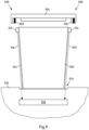
- the Figure 3 shows a schematic side view of an embodiment of a vessel arrangement 300 according to the present application.
- the pot 302 is preferably formed partly from metal and partly from plastic.
- a section 342 can be made of plastic. This section 342 can also form the handle and have an at least partially, preferably completely annular section 343 arranged on the pot edge 303.
- a first coil 312 is arranged on the upper edge of the pot 303.
- a second coil (not shown) is preferably arranged on the opposite side of the upper pot edge 303.
- the at least two electrical pot connections 316 run from the respective coil 312, in particular through the section 342, to the at least two lower pot contacts 320.
- a pot connection 316 can be integrated in the plastic section 342.
- the at least two lower pot contacts 320 are arranged in particular in or on the pot base 306.
- the coils 312 are preferably embedded in the annular section 343 made of plastic and are preferably at least partially covered by a pot cover 344, in particular in the form of a cover 344.
- the section 343 preferably comprises part of the locking mechanism.
- the section 343 can have contours for locking the lid 304 on the pot 302 in the defined locking position.
- a coil 312 can, as in Fig. 3b shown, preferably formed from a yoke 340 or coil core 340.
- the yoke 340 is in particular a U-shaped yoke 340, which can be designed, for example, as a U-shaped sheet metal made of soft magnetic material.
- the coil winding 346 is arranged around this yoke 340.
- a coil 312 can preferably be covered by a plastic cover 344.
- the ends 353, 355 of the yoke 340 can in particular protrude through recesses or openings in the panel 344.
- induction elements 308 are arranged on the lid 304, in particular on the outer lid edge 305.
- the induction elements 308, 310 can be formed as flat elements 308, 310, in particular by metal plates 308, 310. The ones shown have only an example Flat elements 308, 310 have a rectangular shape.
- FIG. 5 shows a schematic view of a further exemplary embodiment of the kitchen appliance 530 according to the application. To avoid repetition, essentially only the differences from the previous exemplary embodiments are described below and reference is otherwise made to the corresponding statements.
- the coils 512, 514 in the present exemplary embodiment have a common third lower pot contact 521, which is connected to the detection device 526 of the device base 532.
- the other two coil contacts can each be guided separately from one another to the detection device 526 of the device base 532.
- the device base 532 has a tool drive 560.
- the tool drive 560 is set up to drive or operate a kitchen appliance tool 562, which can be located in particular in the pot 502.
- a cutting tool 562 is shown as an example as a kitchen appliance tool 562.
- the kitchen base can include a control device that controls and monitors the one heater that is integrated in the pot 502.
- the kitchen appliance tool 562 has different ones depending on the type of lid of the currently attached lid 504 Maximum permissible drive setpoint parameter values may be operated.
- the detection device 526 may preferably include a restriction module.
- the restriction module (not shown) may be configured to limit at least the maximum permissible drive target parameter value based on the identified lid type and a drive criterion (predefined) for the lid type. Each cover type can be assigned a predefined drive criterion.
- the drive criterion can define the maximum permissible drive target parameter value or a corresponding range.
- the kitchen appliance 530 can have an (optical) display 566, for example a display.
- the display 566 may be configured to display the identified lid type.
- an error message and/or an advisory message can be displayed.
- a further (additional) way to reliably distinguish and in particular identify different types of lids is to influence the inductance over the locking path that has to be covered from the non-locked position to the locked position. This can be done, for example, by shaping and/or a defined arrangement of the induction elements 608, 610. This is exemplified in the Figures 6a, 6b illustrated.
- FIG. 7 shows a schematic view of a further exemplary embodiment of the kitchen appliance 730 according to the application. To avoid repetition, essentially only the differences from the previous exemplary embodiments are described below and reference is otherwise made to the corresponding statements.
- the coils 712, 714 are connected in series via a fifth pot connection 751.
- a fifth pot connection 751 an evaluation of the total inductance is particularly important, as in Figure 6b illustrated, advantageous.
- the series connection of the coils 712, 714 offers in particular the possibility of getting by with only two contacts 720, 723, 736, 739 to the device base 732. If the induction elements 708, 710 are arranged in such a way that when the cover 704 is closed, first the coil 712 and then also the further coil 714 are influenced, then the inductance of the series connection increases in two stages (cf. Fig. 6b ). By evaluating the time course of the total inductance (Sum inductance) can then be checked whether the cover 704 is in the correct position on both sides, i.e. in the locked position.
- FIG. 8 shows a schematic view of a further exemplary embodiment of the kitchen appliance 830 according to the application. To avoid repetition, essentially only the differences from the previous exemplary embodiments are described below and reference is otherwise made to the corresponding statements.
- the vessel arrangement 800 can at least partially include the detection device 826.
- the vessel arrangement 800 includes the first and the second measuring module 815, 817.
- a (digital) communication module 857 of the detection device 826 can be set up to transmit the measured induction values to an evaluation module 819.
- the evaluation module 819 is presently integrated in the device base 832, in particular in the device control.
- the vessel arrangement 800 can also include the evaluation module.
- an evaluation of the measured values on the pot 802 can also take place, so that, for example, the locking state and the lid type can be determined and transmitted in digital form.
- FIG. 9 shows a schematic view of a further exemplary embodiment of the kitchen appliance 930 according to the application. To avoid repetition, essentially only the differences from the previous ones are explained below Examples of embodiments are described and otherwise reference is made to the corresponding statements.
- the main difference is that a magnetic field sensor is used instead of a coil and a magnet is used instead of an induction element.
- the at least one magnetic field-based sensor element 912, 914 (two sensor elements 912, 914 are shown here as an example) is a magnetic field sensor 912, 914.
- a magnetic field sensor 912, 914 can be a Hall sensor 912, 914 or a reed switch 912, 914 be.
- the arrangement of the magnetic field sensors 912, 914 on the pot 902 can be similar to the above-described arrangement of the coils on a pot.
- At least one magnet 908, 910 (here, two magnets 908, 910 are provided as an example) is provided as a magnet-based counter element 908, 910 in the present exemplary embodiment.
- the arrangement of the magnets 908, 910 on the lid 904 can be similar to the above-described arrangement of the induction elements on a lid.
- the at least one magnet 908, 910 comes into the detection range of the at least one magnetic field sensor 912, 914.
- the change in the magnetic field can be detected by the magnetic field sensor 912, 914.
- the magnetic field sensor 912, 914 outputs the first sensor data.
- the at least one magnet 908, 910 is arranged on the lid 904 in such a way that a detectable magnetic field change, which leads to an output of the first sensor data, can only be present when the lid 904 is in the locked position, can be determined by the detection of the first sensor data, a locking state of the lid 904 can be detected in a reliable manner.
- each magnetic field sensor 912, 914 is connected to the detection device 926 in order in particular to provide at least the first sensor data for evaluation.
- the evaluation can be carried out similarly to the previous exemplary embodiments.
- the transmitter magnets 908, 910 arranged on the cover 904 and corresponding to the magnetic field sensor 912, 914 trigger, in particular, as described, a detection signal or the first sensor data in the magnetic field sensors 912, 914 when the cover 904 is closed and correctly locked.
- Detection or identification of the cover type is also possible here, for example if magnetic field sensors 912, 914 are used, which allow an evaluation of the magnetic field direction of the magnet 908, 910 located in the detection area.
- a characteristic signal pattern results for the different types of lids.
- An identification of a specific lid type is in the exemplary embodiment Figure 9 particularly possible using Table 2, as already described.
- a counter-element in the form of a transmitter magnet is arranged on the pot and a guide element is arranged in the lid as a further counter-element, the magnetic field when the lid is (correctly) locked (in a defined manner) through or to the associated magnetic field sensor.
- the arrangement of the detection device 926 for a magnetic field sensor 912, 914 can be similar to inductive detection in the pot or in the device base. Furthermore, it is conceivable that by placing several magnets, the signal curve is also analyzed when closing so that more reliable detection can take place.
- the Figure 10 shows schematic views of an embodiment of a vessel arrangement according to the present application in various Lid states and an exemplary induction value curve 1071 or signal curve of the sensors 1071.
- the vessel arrangement can be formed similarly to a vessel arrangement in one of the previous figures.
- the differences between the vessel arrangement and the previous exemplary embodiments are essentially described below.
- the cover shown has first counter-elements 1008, 1010 and additional counter-elements 1052, 1054.
- the first counter-elements 1008, 1010 can, for example, be magnets 1008, 1010 with a first pole orientation and the additional counter-elements 1052, 1054 can be additional magnets 1052, 1054 with a second pole orientation that differs from the first pole orientation.
- the additional magnets 1052, 1054 are arranged on the lid, in particular on the edge of the lid, in such a way that the magnetic field sensors 1012, 1014 are only influenced in the unlocked position, as shown in Figure 10 Induction is shown in the left section.
- Sensor signal curve 1071 shown can at least determine whether the lid is in the (defined) unlocked position (denoted by reference numeral 1073) or the lid 1010 is in the defined locking position (denoted by reference numeral 1077).
- the position in between, i.e. in particular during the locking movement, is designated by reference number 1075.
- a first sensor signal curve can be determined by the detection device (in particular as long as the additional magnets 1052, 1054 mentioned are in the detection range of the respective magnetic field sensors 1012, 1014.
- the magnets 1008, 1010 enter the respective detection range of the magnetic field sensors 1012, 1014.
- a different sensor signal curve is detected by the detection device due to the different pole alignment (in particular as long as the magnets 1008, 1010 are in the respective detection range of the magnetic field sensors 1012, 1014 are present, so the lid is in the locked position).
- a locked lid position can be distinguished from the unlocked lid position in a simple and reliable manner.
- FIG. 11 shows a schematic view of a further exemplary embodiment of a kitchen appliance 1130 according to the present application. To avoid repetition, essentially only the differences from the previous exemplary embodiments are described below and reference is otherwise made to the corresponding statements.
- the kitchen appliance 1130 includes a mechanical locking mechanism 1170 with a lid drive 1174 (also called locking actuator).
- the lid drive 1174 is mechanically coupled to the lid 1104 via a mechanical connection 1172, which is basically known.
- the lid drive 1174 can be set up to (automatically) move the lid 1104 between an unlocked position of the lid 1104 and a locked position of the lid 1104.
- the detection device 1126 can be communicatively coupled to the lid drive 1174.
- the detection device 1126 can in particular be set up to detect, preferably measure, at least one cover drive parameter value (e.g. position and/or actuator current).
- the detection device 1126 may further be configured to detect the locking state of the vessel assembly 1100 based on the detected lid drive parameter value.
- FIG. 12 A possible implementation of this detection is in the Figure 12 illustrated graphically.
- the lid 1204 or parts of the lid 1204 can be moved relative to the pot 1202 when closing or locking, for example bayoneted by a rotary movement.
- the cover drive reaches different end positions 1280, 1282, 1284, which can be evaluated and in particular determined, for example, by measuring, by the detection device, the position and actuator current.
- the lid 1204 In the upper section of the Figure 12 the lid 1204 is not locked. The locking movement starts at the end position 1280, in particular in the unlocked position. In the middle section of the Figure 12 there is a lid 1204. The lid 1204 has been moved to the second end position 1282. The lid 1204 is therefore in the locked state or position. In the lower section of the Figure 12 there is no lid. The lid drive reaches the third end position 1284. From this, the detection device can conclude that there is no lid.
- the reference number 1287 denotes the axis as the position of the lid drive.
- Reference number 1281 denotes the unlocked position, reference number 1283 that locked position, and reference numeral 1285 the state that there is no lid.
- the detection device can also be used to compare the detected time-dependent and/or position-dependent electrical signals and mechanical signals.
- the reference number 1389 (or 1489) denotes the locked state and the reference number 1391 (or 1491) denotes the unlocked state.
- the Figure 13 shows in particular the case where the lid was (correctly) locked.
- a locking state is established almost simultaneously by the detection device by evaluating the at least one sensor signal or first sensor data (as described) (upper section of the Figure 13 ) and the at least one lid drive parameter (as described) (lower section of the Figure 13 ) was determined.
- Sufficient synchronicity exists in particular when the respective change in state is detected within a predefined time window ⁇ B or tolerance range ⁇ B.
- a cover can only be assessed as (correctly) locked by the detection device, i.e. a locking state can be determined, if the signals from both detection paths change from the “unlocked” state to the “locked” state within the tolerance range ⁇ B (cf. Fig. 13 ).
- the Figure 15 shows a diagram of an exemplary embodiment of a method according to the present application for determining a locking state in a vessel arrangement according to one of the previous exemplary embodiments.
- a first sensor data output by the magnetic field-based sensor element is obtained by a detection device, as already described.
- a locking state of the vessel arrangement is detected by the detection device, based on the detected first sensor data and at least one locking criterion, as already described.
Landscapes
- Engineering & Computer Science (AREA)
- Food Science & Technology (AREA)
- Mechanical Engineering (AREA)
- Physics & Mathematics (AREA)
- General Physics & Mathematics (AREA)
- Manufacturing & Machinery (AREA)
- Cookers (AREA)
Abstract
Die Anmeldung betrifft eine Gefäßanordnung (100, 200, 300, 500, 700, 800, 900, 1100) für ein Küchengerät (230, 530, 730, 830, 930, 1130), umfassend ein Speiseaufnahmeelement (102, 202, 302, 502, 602, 702, 802, 902, 1002, 1102) und mindestens einen Deckel (104, 204, 304, 504, 704, 804, 904, 1104), eingerichtet zum Verschließen einer Öffnung des Speiseaufnahmeelements (102, 202, 302, 502, 602, 702, 802, 902, 1002, 1102), wobei der Deckel (104, 204, 304, 504, 704, 804, 904, 1104) relativ zu dem Speiseaufnahmeelement (102, 202, 302, 502, 602, 702, 802, 902, 1002, 1102) zwischen einer ersten Betriebsposition und einer zweiten sich von der ersten Betriebsposition unterscheidenden Betriebsposition bewegbar ist, wobei der Deckel (104, 204, 304, 504, 704, 804, 904, 1104) mindestens ein erstes magnetfeldbasiertes Gegenelement (108, 208, 210, 308, 508, 510, 608, 610, 708, 710, 808, 810, 908, 910, 1008, 1010, 1108) und das Speiseaufnahmeelement (102, 202, 302, 502, 602, 702, 802, 902, 1002, 1102) mindestens ein mit einer Detektionseinrichtung (126, 226, 526, 726, 826, 926, 1126) verbindbares magnetfeldbasiertes Sensorelement (112, 212, 214, 312, 512, 514, 612, 614, 712, 714, 812, 814, 912, 914, 1012, 1014, 1112) aufweist, wobei die Detektionseinrichtung (126, 226, 526, 726, 826, 926, 1126) eingerichtet ist zum Detektieren eines zweiten Betriebszustands des Deckels (104, 204, 304, 504, 704, 804, 904, 1104), wobei das magnetfeldbasierte Sensorelement (112, 212, 214, 312, 512, 514, 612, 614, 712, 714, 812, 814, 912, 914, 1012, 1014, 1112) eingerichtet ist zum Ausgeben des ersten Sensordatums nur bei einer Detektion des ersten magnetfeldbasierten Gegenelements (108, 208, 210, 308, 508, 510, 608, 610, 708, 710, 808, 810, 908, 910, 1008, 1010, 1108) in dem Erfassungsbereich des magnetfeldbasierten Sensorelements (112, 212, 214, 312, 512, 514, 612, 614, 712, 714, 812, 814, 912, 914, 1012, 1014, 1112), wobei das erste magnetfeldbasierte Gegenelement (108, 208, 210, 308, 508, 510, 608, 610, 708, 710, 808, 810, 908, 910, 1008, 1010, 1108) in dem Deckel (104, 204, 304, 504, 704, 804, 904, 1104) derart angeordnet ist, dass das magnetfeldbasierte Gegenelement (108, 208, 210, 308, 508, 510, 608, 610, 708, 710, 808, 810, 908, 910, 1008, 1010, 1108) nur dann in dem Erfassungsbereich des magnetfeldbasierten Sensorelements (112, 212, 214, 312, 512, 514, 612, 614, 712, 714, 812, 814, 912, 914,1012,1014, 1112) ist, wenn sich der Deckel (104, 204, 304, 504, 704, 804, 904, 1104) in der zweiten Betriebsposition befindet.The application relates to a vessel arrangement (100, 200, 300, 500, 700, 800, 900, 1100) for a kitchen appliance (230, 530, 730, 830, 930, 1130), comprising a food receiving element (102, 202, 302, 502 , 602, 702, 802, 902, 1002, 1102) and at least one lid (104, 204, 304, 504, 704, 804, 904, 1104), designed to close an opening of the food receiving element (102, 202, 302, 502 , 602, 702, 802, 902, 1002, 1102), wherein the lid (104, 204, 304, 504, 704, 804, 904, 1104) is relative to the food receiving element (102, 202, 302, 502, 602, 702 , 802, 902, 1002, 1102) is movable between a first operating position and a second operating position that differs from the first operating position, wherein the cover (104, 204, 304, 504, 704, 804, 904, 1104) has at least a first magnetic field-based Counter element (108, 208, 210, 308, 508, 510, 608, 610, 708, 710, 808, 810, 908, 910, 1008, 1010, 1108) and the food receiving element (102, 202, 302, 502, 602, 702, 802, 902, 1002, 1102) at least one magnetic field-based sensor element (112, 212, 214, 312, 512, 514, 612, 614) that can be connected to a detection device (126, 226, 526, 726, 826, 926, 1126). , 712, 714, 812, 814, 912, 914, 1012, 1014, 1112), wherein the detection device (126, 226, 526, 726, 826, 926, 1126) is set up to detect a second operating state of the lid (104, 204, 304, 504, 704, 804, 904, 1104), the magnetic field-based sensor element (112, 212, 214, 312, 512, 514, 612, 614, 712, 714, 812, 814, 912, 914, 1012, 1014, 1112) is set up to output the first sensor data only when the first magnetic field-based counter element (108, 208, 210, 308, 508, 510, 608, 610, 708, 710, 808, 810, 908, 910, 1008, 1010, 1108) in the detection range of the magnetic field-based sensor element (112, 212, 214, 312, 512, 514, 612, 614, 712, 714, 812, 814, 912, 914, 1012, 1014, 1112), the first being magnetic field-based Counter element (108, 208, 210, 308, 508, 510, 608, 610, 708, 710, 808, 810, 908, 910, 1008, 1010, 1108) in the cover (104, 204, 304, 504, 704, 804, 904, 1104) is arranged such that the magnetic field-based counter element (108, 208, 210, 308, 508, 510, 608, 610, 708, 710, 808, 810, 908, 910, 1008, 1010, 1108) only then in the detection range of the magnetic field-based sensor element (112, 212, 214, 312, 512, 514, 612, 614, 712, 714, 812, 814, 912, 914,1012,1014, 1112) when the cover (104 , 204, 304, 504, 704, 804, 904, 1104) is in the second operating position.
Description
Die Anmeldung betrifft eine Gefäßanordnung für ein Küchengerät, umfassend ein Speiseaufnahmeelement und einen hierzu korrespondierenden Deckel. Darüber hinaus betrifft die Anmeldung ein Küchengerät und ein Verfahren.The application relates to a vessel arrangement for a kitchen appliance, comprising a food receiving element and a lid corresponding thereto. In addition, the application concerns a kitchen appliance and a process.
Aus dem Stand der Technik sind Küchenmaschinen bekannt, die zum zumindest teilautomatischen Zubereiten von Speisen eingerichtet sind. Derartige Küchenmaschinen, aber auch andere Küchengeräte, können mindestens eine Gefäßanordnung umfassen. Eine Gefäßanordnung kann ein Speiseaufnahmeelement, beispielsweise in Form eines Topfs, und mindestens einen Deckel umfassen. Der Deckel ist eingerichtet zum Verschließen bzw. Abdecken der Topföffnung. Der Deckel kann auch weitere Funktionen während der Speisenzubereitung ermöglichen bzw. dafür genutzt werden.Kitchen machines are known from the prior art and are set up to prepare food at least partially automatically. Such kitchen machines, but also other kitchen appliances, can include at least one vessel arrangement. A vessel arrangement can include a food receiving element, for example in the form of a pot, and at least one lid. The lid is designed to close or cover the pot opening. The lid can also enable or be used for other functions during food preparation.
Insbesondere kann es für einen sicheren Betrieb eines Küchengeräts erforderlich sein, dass der Deckel mit dem Speiseaufnahmeelement in einer bestimmten Betriebsposition ist, insbesondere verriegelt werden kann. Aus dem Stand der Technik ist es daher bekannt, dass ein Deckel relativ zu dem Speiseaufnahmeelement von einer ersten Betriebsposition, wie eine unverriegelte Betriebsposition, in eine zweite Betriebsposition, wie eine verriegelte Betriebsposition, bewegbar ist. Beispielsweise kann der Nutzer den Deckel entsprechend bewegen oder das Küchengerät kann einen Deckelantrieb umfassen, eingerichtet zum (automatischen) Verfahren eines Deckels zumindest zwischen der unverriegelten Position und der verriegelten Position.In particular, for safe operation of a kitchen appliance, it may be necessary for the lid with the food receiving element to be in a specific operating position, in particular to be able to be locked. It is therefore known from the prior art that a lid can be moved relative to the food receiving element from a first operating position, such as an unlocked operating position, to a second operating position, such as a locked operating position. For example, the user can move the lid accordingly or the kitchen appliance can include a lid drive, set up to (automatically) move a lid at least between the unlocked position and the locked position.
Die Durchführung einer bestimmten Küchengerätefunktion durch ein Küchengerät ist regelmäßig nur dann zulässig, wenn sich ein Deckel auf dem Speiseaufnahmeelement in einer bestimmten Betriebsposition, insbesondere der verriegelten Position, befindet, also die Gefäßanordnung in einem zweiten Betriebszustand ist, insbesondere dem Verriegelungszustand.The implementation of a specific kitchen appliance function by a kitchen appliance is generally only permitted if a lid on the food receiving element is in a specific operating position, in particular the locked position. is located, i.e. the vessel arrangement is in a second operating state, in particular the locking state.
Zum Erkennen bzw. Erfassen eines Verriegelungszustands einer Gefäßanordnung ist es aus dem Stand der Technik bekannt, Mikroschalter einzusetzen. Beispielsweise kann eine Erkennung der Verriegelungsposition des Deckels durch Abfrage der Position von Verriegelungswalzen des Speiseaufnahmeelements/Deckels über Mikroschalter in Kombination mit einer Auswertung des Strombedarfs des Deckelantriebs erfolgen. Zusätzlich kommt in der Regel noch ein Mikroschalter zum Einsatz, der durch einen verriegelten Deckel betätigt werden muss.To recognize or detect a locking state of a vessel arrangement, it is known from the prior art to use microswitches. For example, the locking position of the lid can be detected by querying the position of locking rollers of the food receiving element/lid via microswitches in combination with an evaluation of the power requirement of the lid drive. In addition, a microswitch is usually used, which must be activated by a locked lid.
Ferner sind aus dem Stand der Technik Konzepte bekannt, die ebenfalls über elektrische Schalter einen in der Verriegelungsposition befindlichen Deckel detektieren. Ein solcher elektrischer Schalter wird je nach Küchengerät direkt durch den Deckel oder indirekt über mechanische Stößel, Hebel oder ähnliches betätigt.Furthermore, concepts are known from the prior art which also detect a lid that is in the locking position via electrical switches. Depending on the kitchen appliance, such an electrical switch is operated directly through the lid or indirectly via mechanical plungers, levers or similar.
Diese Detektionsmechanismen haben jedoch verschiedenste Nachteile. Insbesondere ist der Aufwand einer Implementierung aufwendig. Dies gilt besonders für den Fall, wenn das Küchengerät eine Mehrzahl von Gefäßanordnungen und/oder die Gefäßanordnung eine Mehrzahl von Deckeln umfasst.However, these detection mechanisms have various disadvantages. In particular, the effort involved in implementation is complex. This applies particularly to the case when the kitchen appliance comprises a plurality of vessel arrangements and/or the vessel arrangement comprises a plurality of lids.
Um bei den bekannten Detektionsmechanismen die Verriegelungsinformation von einem Deckelbereich zu einer in einer Gerätebasis angeordneten Detektionseinrichtung zu übertragen, muss ein Übertragungspfad vorgesehen sein, der die Verriegelungsinformation an die entsprechende Einkopplungsstelle der Gerätebasis überträgt. Ferner muss die Verriegelungsinformation in Form eines oder mehrerer elektrischer Signale bereitgestellt werden, damit die Detektionseinrichtung diese Information auswerten kann, um den Verriegelungszustand detektieren zu können.In order to transmit the locking information from a lid area to a detection device arranged in a device base in the known detection mechanisms, a transmission path must be provided which transmits the locking information to the corresponding coupling point of the device base. Furthermore, the locking information must be provided in the form of one or more electrical signals so that the detection device can evaluate this information in order to be able to detect the locking state.
Die verschiedenen, bekannten Detektionsmechanismen können im Wesentlichen in zwei Gruppen eingeteilt werden. Die Einteilung kann insbesondere davon abhängen, an welcher Stelle des Küchengeräts das elektrische Signal generiert wird, welches die Verriegelungsinformation (d.h. insbesondere: Deckel ist in der Verriegelungsposition) enthält und/oder diese repräsentiert.The various known detection mechanisms can essentially be divided into two groups. The classification can depend in particular on where on the kitchen appliance the electrical signal is generated, which contains and/or represents the locking information (i.e. in particular: the lid is in the locking position).
Bei der ersten Gruppe wird die Verriegelungsinformation zwischen der Gefäßanordnung und der Gerätebasis des Küchengeräts auf mechanischem Weg übertragen. Die Umwandlung in ein elektrisches Signal erfolgt erst in der Gerätebasis.In the first group, the locking information is transmitted mechanically between the vessel assembly and the appliance base of the kitchen appliance. The conversion into an electrical signal only takes place in the device base.
Ein entsprechender Detektionsmechanismus ist, insbesondere bei verschiedenen Topf- bzw. Speiseaufnahmeelementdurchmessern, mit der Herausforderung verbunden, die mechanische Bewegung an die richtige Position der Gerätebasis zu übertragen. Die hierzu erforderlichen mechanischen Übertragungselemente unterliegen aufgrund der bewegten Teile einem hohen Verschmutzungsrisiko. In besonders ungünstigen Fällen kann eine Verschmutzung zu einem Klemmen und/oder Blockieren des mechanischen Mechanismus führen. Dies wiederum kann zu einer fehlerhaften Verriegelungsdetektion führen.A corresponding detection mechanism is associated with the challenge of transmitting the mechanical movement to the correct position on the device base, especially with different pot or food receiving element diameters. The mechanical transmission elements required for this are subject to a high risk of contamination due to the moving parts. In particularly unfavorable cases, contamination can lead to jamming and/or blocking of the mechanical mechanism. This in turn can lead to incorrect lock detection.
Hinzu kommt, dass die Reinigung des mechanischen Mechanismus Schwierigkeiten bereiten kann, insbesondere wenn aus Bauraumgründen filigrane, mechanische Strukturen zum Einsatz kommen.In addition, cleaning the mechanical mechanism can cause difficulties, especially if delicate mechanical structures are used for space reasons.
Soll neben dem Verriegelungszustand der Gefäßanordnung zusätzlich eine Möglichkeit bereitgestellt werden, den Deckeltyp aus einer Mehrzahl von möglichen unterschiedlichen Deckeltypen zu bestimmen (z.B. bei mehreren unterschiedlichen Deckeln pro Topf), so muss das Erkennungssignal in geeigneter Weise codierbar sein.If, in addition to the locking state of the vessel arrangement, an additional possibility is to be provided to determine the lid type from a plurality of possible different lid types (e.g. with several different lids per pot), then the detection signal must be able to be coded in a suitable manner.
Bei einer mechanischen Abtastung des Deckels führt dies zu einem deutlichen Zusatzaufwand. Grund hierfür ist insbesondere, dass zur Übermittlung der Zusatzinformation entweder die Signalanzahl erhöht werden muss (was zusätzliche mechanische Übertragungsmechanismen erfordert) oder eine mechanische Bewegung eines Elementes des mechanischen Mechanismus detaillierter ausgewertet werden muss (z.B. unterschiedliche Stößelhübe je nach Deckeltyp).If the lid is scanned mechanically, this leads to significant additional effort. The reason for this is in particular that in order to transmit the additional information, either the number of signals must be increased (which means additional requires mechanical transmission mechanisms) or a mechanical movement of an element of the mechanical mechanism must be evaluated in more detail (e.g. different ram strokes depending on the cover type).
Abhängig von der Ausführung bringen mechanische Übertragungselemente auch ein erhöhtes Manipulationsrisiko mit sich. So können die entsprechenden Schalter und/oder Mechaniken von einem Nutzer manuell betätigt werden, um eine Verriegelung vorzutäuschen. Um dies zu verhindern, sind zusätzliche mechanische Strukturen erforderlich. Dies wiederum erschwert die Reinigung noch weiter und erhöht zudem den Implementierungsaufwand.Depending on the design, mechanical transmission elements also entail an increased risk of manipulation. The corresponding switches and/or mechanisms can be operated manually by a user to simulate a lock. To prevent this, additional mechanical structures are required. This in turn makes cleaning even more difficult and also increases the implementation effort.
Bei der zweiten Gruppe wird der Verriegelungszustand des Deckels zwischen der Gefäßanordnung und der Gerätebasis elektrisch übertragen. Anders ausgedrückt, die Wandlung in ein elektrisches Signal erfolgt bereits an der Gefäßanordnung. Aufgrund der Umgebungsbedingungen (z.B. Feuchtigkeit, Schmutz, Temperatur, Spülmaschinenumgebung), denen eine Gefäßanordnung regelmäßig ausgesetzt ist, ist ein Abtasten des Deckels mit Hilfe von Mikroschaltern problematisch. Grund hierfür ist, dass die Mikroschalter eine Abdichtung benötigen. Dies führt zu einem erhöhten Implementierungsaufwand. Zudem handelt es sich bei einer Abdichtung um ein Verschleißelement. Ein Verschleiß kann sich insbesondere negativ auf die Lebensdauer der Gefäßanordnung auswirken.In the second group, the locking state of the lid is electrically transmitted between the vessel assembly and the device base. In other words, the conversion into an electrical signal already takes place at the vascular arrangement. Due to the environmental conditions (e.g. humidity, dirt, temperature, dishwasher environment) to which a vessel arrangement is regularly exposed, scanning the lid using microswitches is problematic. The reason for this is that the micro switches require a seal. This leads to increased implementation effort. In addition, a seal is a wear element. Wear can have a particularly negative impact on the service life of the vessel arrangement.
Die beschriebenen Detektionsmechanismen weisen somit Nachteile in den Bereichen Robustheit, Komplexität und/oder Bauraum auf.The detection mechanisms described therefore have disadvantages in the areas of robustness, complexity and/or installation space.
Daher liegt der Anmeldung die Aufgabe zugrunde, eine Möglichkeit zur Detektion eines zweiten Betriebszustands, insbesondere eines Verriegelungszustands, bei einer Gefäßanordnung für ein Küchengerät bereitzustellen, welche robuster und/oder einfacher ausgebildet ist und/oder weniger Bauraum benötigt.The application is therefore based on the object of providing a possibility for detecting a second operating state, in particular a locking state, in a vessel arrangement for a kitchen appliance, which is designed to be more robust and/or simpler and/or requires less installation space.
Diese Aufgabe wird gemäß einem ersten Aspekt der Anmeldung gelöst durch eine Gefäßanordnung für ein Küchengerät nach Anspruch 1. Die Gefäßanordnung umfasst ein Speiseaufnahmeelement. Die Gefäßanordnung umfasst mindestens einen Deckel.This object is achieved according to a first aspect of the application by a vessel arrangement for a kitchen appliance according to claim 1. The vessel arrangement comprises a food receiving element. The vessel arrangement includes at least one lid.
Der Deckel ist eingerichtet zum Verschließen einer Öffnung des Speiseaufnahmeelements. Der Deckel ist relativ zu dem Speiseaufnahmeelementzwischen einer ersten Betriebsposition und einer sich von der ersten Betriebsposition unterscheidenden Betriebsposition bewegbar. Der Deckel weist mindestens ein erstes magnetfeldbasiertes Gegenelement auf. Das Speiseaufnahmeelement weist mindestens ein mit einer Detektionseinrichtung verbindbares magnetfeldbasiertes Sensorelement auf. Die Detektionseinrichtung ist eingerichtet zum Detektieren eines zweiten Betriebszustands (bzw. der zweiten Betriebsposition) des Deckels, basierend auf einem ersten Sensordatum. Das magnetfeldbasierte Sensorelement ist eingerichtet zum Ausgeben des ersten Sensordatums nur bei einer Detektion des ersten magnetfeldbasierten Gegenelements in dem Erfassungsbereich des magnetfeldbasierten Sensorelements. Das mindestens eine erste magnetfeldbasierte Gegenelement ist in dem Deckel derart angeordnet, dass das magnetfeldbasierte Gegenelement zumindest dann in dem Erfassungsbereich des magnetfeldbasierten Sensorelements ist, wenn sich der Deckel in der zweiten Betriebsposition befindet.The lid is designed to close an opening of the food receiving element. The lid is movable relative to the food receiving member between a first operating position and an operating position other than the first operating position. The cover has at least one first magnetic field-based counter element. The food receiving element has at least one magnetic field-based sensor element that can be connected to a detection device. The detection device is set up to detect a second operating state (or the second operating position) of the lid based on a first sensor data. The magnetic field-based sensor element is set up to output the first sensor data only when the first magnetic field-based counter element is detected in the detection area of the magnetic field-based sensor element. The at least one first magnetic field-based counter element is arranged in the lid in such a way that the magnetic field-based counter element is at least in the detection range of the magnetic field-based sensor element when the lid is in the second operating position.
Im Gegensatz zum Stand der Technik wird anmeldungsgemäß eine Möglichkeit zur Detektion eines zweiten Betriebszustands, insbesondere eines Verriegelungszustands, eines Deckels einer Gefäßanordnung für ein Küchengerät bereitgestellt, welche robuster und einfacher ausgebildet ist und insbesondere weniger Bauraum benötigt, indem in dem Deckel mindesten ein Gegenelement und in dem Speiseaufnahmeelement mindestens ein hierzu korrespondierendes Sensorelement angeordnet ist, wobei das Sensorelement insbesondere nur dann ein erstes Sensordatum ausgibt, wenn sich der Deckel in der zweiten Betriebsposition befindet, insbesondere in der verriegelten Position. Besonders bevorzugt ist das Sensorelement eine Spule und das Gegenelement ein Induktionselement oder das Sensorelement ist ein Magnetfeldsensor und das Gegenelement ein Magnet, wie noch näher ausgeführt wird.In contrast to the prior art, according to the application, a possibility for detecting a second operating state, in particular a locking state, of a lid of a vessel arrangement for a kitchen appliance is provided, which is designed to be more robust and simple and in particular requires less installation space, in that at least one counter element and in the lid At least one corresponding sensor element is arranged on the food receiving element, the sensor element in particular only outputting a first sensor data when the lid is in the second operating position, in particular in the locked position. Particularly preferably, the sensor element is a coil and the counter-element is an induction element or the sensor element a magnetic field sensor and the counter element a magnet, as will be explained in more detail.
Die anmeldungsgemäße Gefäßanordnung ist für eine Verwendung in einem Küchengerät eingerichtet. Das Küchengerät ist insbesondere eine Küchenmaschine, eingerichtet zum Zubereiten von Speisen und/oder Getränken. Das Zubereiten kann zumindest teilweise automatisiert erfolgen.The vessel arrangement according to the application is set up for use in a kitchen appliance. The kitchen appliance is in particular a food processor, set up for preparing food and/or drinks. The preparation can be at least partially automated.
Die Gefäßanordnung umfasst mindestens ein Speiseaufnahmeelement und mindestens einen ersten zu dem Speiseaufnahmeelement strukturell korrespondierenden Deckel. Dies meint insbesondere, dass eine (Topf-)Öffnung durch den ersten Deckel verschließbar bzw. abdeckbar ist und der Deckel insbesondere auf die Topföffnung auflegbar ist.The vessel arrangement comprises at least one food-receiving element and at least one first lid that structurally corresponds to the food-receiving element. This means in particular that a (pot) opening can be closed or covered by the first lid and the lid can in particular be placed on the pot opening.
Ein Speiseaufnahmeelement ist insbesondere eingerichtet zum Aufnehmen von Speisen und vorzugsweise ein Topf, auch Kochtopf genannt, eine Pfanne, oder dergleichen. Insbesondere ist unter einem Speiseaufnahmeelement anmeldungsgemäß ein füllbares Gefäß bzw. ein füllbarer Behälter zu verstehen, welches/r zum Zubereiten von Speisen oder Getränken eingerichtet ist, insbesondere zum Garen oder Kochen von Warmspeisen.A food receiving element is in particular designed to receive food and preferably a pot, also called a cooking pot, a pan, or the like. In particular, according to the application, a food receiving element is to be understood as meaning a fillable vessel or a fillable container which is set up for preparing food or drinks, in particular for cooking or cooking hot dishes.
Vorzugsweise korrespondiert das Speiseaufnahmeelement (strukturell) zu einer Gerätebasis des Küchengeräts. Das Speiseaufnahmeelement kann beispielswiese zumindest teilweise aus Kunststoff, zumindest teilweise aus Metall und/oder zumindest teilweise aus Glas gebildet sein.Preferably, the food receiving element corresponds (structurally) to a device base of the kitchen appliance. The food receiving element can, for example, be formed at least partially from plastic, at least partially from metal and/or at least partially from glass.
Unter einem Deckel ist anmeldungsgemäß insbesondere ein Verschluss- und/oder Abdeckelement zu verstehen, mit der die Öffnung des Speiseaufnahmeelements zumindest teilweise (z.B. vollständig) verschließbar bzw. abdeckbar ist. Der Deckel kann wiederum eine Deckelöffnung aufweisen, beispielsweise für eine Anordnung, insbesondere Kopplung, eines Zubehörteils.According to the application, a lid is to be understood in particular as a closure and/or covering element with which the opening of the food receiving element can be at least partially (eg completely) closed or covered. The lid can in turn have a lid opening, for example for an arrangement, in particular coupling, of an accessory.
Der Deckel ist anmeldungsgemäß zumindest zwischen einer ersten Betriebsposition und einer zweiten Betriebsposition bewegbar. Die erste Betriebsposition kann eine Deckelposition sein, in der die Gefäßanordnung nicht betriebsbereit ist, und die zweite Betriebsposition kann eine Deckelposition sein, in der die Gefäßanordnung betriebsbereit ist. In der ersten Betriebsposition ist der Deckel insbesondere nicht betriebsbereit an bzw. auf dem Speiseaufnahmeelement positioniert. Der Deckel bzw. die Gefäßanordnung ist insbesondere in einem ersten Betriebszustand. In der zweiten Betriebsposition ist der Deckel insbesondere betriebsbereit an bzw. auf dem Speiseaufnahmeelement positioniert. Der Deckel bzw. die Gefäßanordnung ist insbesondere in einem zweiten Betriebszustand.According to the application, the cover is movable at least between a first operating position and a second operating position. The first operating position may be a lid position in which the vessel assembly is not operational, and the second operating position may be a lid position in which the vessel assembly is operational. In the first operating position, the lid is positioned in particular not ready for operation on or on the food receiving element. The lid or the vessel arrangement is in particular in a first operating state. In the second operating position, the lid is positioned, in particular ready for operation, on or on the food receiving element. The lid or the vessel arrangement is in particular in a second operating state.
Die erste Betriebsposition kann vorzugsweise eine unverriegelte Betriebsposition und die zweite Betriebsposition eine verriegelte Betriebsposition sein.The first operating position may preferably be an unlocked operating position and the second operating position may be a locked operating position.
Vorzugsweise kann der Deckel mit dem Speiseaufnahmeelement verriegelt werden. Insbesondere ist der erste Deckel relativ zu dem Speiseaufnahmeelement zwischen einer unverriegelten Position und einer (definierten) verriegelten Position bewegbar. In der verriegelten Position befindet sich der Deckel bzw. die Gefäßanordnung in einem Verriegelungszustand. Eine anmeldungsgemäße Verriegelung ist insbesondere eine mechanische Verriegelung bzw. Blockierung des Deckels.Preferably, the lid can be locked to the food receiving element. In particular, the first lid is movable relative to the food receiving element between an unlocked position and a (defined) locked position. In the locked position, the lid or the vessel assembly is in a locked state. A lock according to the application is in particular a mechanical lock or blocking of the lid.
Vorzugsweise kann die Gefäßanordnung mindestens einen (mechanischen) Verriegelungsmechanismus umfassen, eingerichtet zum Verriegeln des ersten Deckels mit dem Speiseaufnahmeelement in einer Verriegelungsposition bzw. verriegelten Position des Deckels. Beispielsweise kann die Verriegelung über mindestens ein an dem Speiseaufnahmeelement angeordnetes Klemmelement (z.B. Walze) (in bekannter Weise) hergestellt werden. Insbesondere kann eine Bajonette-Verriegelung vorgesehen sein. Es versteht sich, dass andere Verriegelungsmechanismen verwendet werden können.Preferably, the vessel arrangement can comprise at least one (mechanical) locking mechanism, designed to lock the first lid with the food receiving element in a locking position or locked position of the lid. For example, the lock can be produced (in a known manner) via at least one clamping element (eg roller) arranged on the food receiving element. In particular, a bayonet lock can be provided. It is understood that other locking mechanisms may be used.
Ein Deckel kann durch einen Deckelantrieb bzw. Verriegelungsaktor automatisch verfahrbar sein oder manuell durch eine Nutzeraktion von der ersten Betriebsposition in die (definierte) zweite Betriebsposition bewegbar sein.A lid can be moved automatically by a lid drive or locking actuator or can be moved manually by a user action from the first operating position to the (defined) second operating position.
Anmeldungsgemäß ist erkannt worden, dass in einfacher Weise ein zweiter Betriebszustand, insbesondere ein Verriegelungszustand detektierbar ist, wenn in dem Topf ein oder mehrere berührungslos arbeitende Sensorelemente und in dem Deckel ein oder mehrere Gegenelemente derart in dem Speiseaufnahmeelement bzw. dem Deckel angeordnet sind, dass eine Beeinflussung des Sensorelements durch ein Gegenelement zumindest in der zweiten Betriebsposition erfolgt, insbesondere nur in der zweiten Betriebsposition erfolgt, also insbesondere in dem Verriegelungszustand des Deckels. Insbesondere kann das mindestens eine Gegenelement derart in bzw. an dem Deckel angeordnet sein, dass das Gegenelement nur dann in den Erfassungsbereich bzw. Detektionsbereich des in bzw. an dem Speiseaufnahmeelement angeordneten Sensorelements gelangen kann, wenn der Deckel (ordnungsgemäß) an dem Speiseaufnahmeelement ordnungsgemäß positioniert ist und/oder wird (z.B. ordnungsgemäß von der ersten Betriebsposition in die zweite Betriebsposition bewegt wird), insbesondere verriegelt ist und/oder wird.According to the application, it has been recognized that a second operating state, in particular a locking state, can be easily detected if one or more non-contact sensor elements are arranged in the pot and one or more counter-elements in the lid are arranged in the food receiving element or the lid in such a way that a Influencing the sensor element by a counter element takes place at least in the second operating position, in particular only in the second operating position, i.e. in particular in the locked state of the lid. In particular, the at least one counter-element can be arranged in or on the lid in such a way that the counter-element can only enter the detection area or detection area of the sensor element arranged in or on the food receiving element if the lid is properly positioned (properly) on the food receiving element is and/or is (e.g. is properly moved from the first operating position to the second operating position), in particular is and/or is locked.
Magnetfeldbasiert meint vorliegend insbesondere, dass durch ein magnetfeldbasiertes Gegenelement eine detektierbare Beeinflussung des magnetfeldbasierten Sensorelements erfolgt. Vorzugsweise kann durch das magnetfeldbasierte Sensorelement eine Magnetfeldänderung in dem Erfassungsbereich des Sensorelements durch ein zu dem Sensorelement korrespondierendes Gegenelement detektiert werden. Anders ausgedrückt, ein Gegenelement ist insbesondere zum Beeinflussen eines Magnetfelds in dem Erfassungsbereich eines Sensorelements eingerichtet. Ein Sensorelement ist insbesondere eingerichtet zum Detektieren einer Magnetfeldänderung im Erfassungsbereich des Sensors. Eine Magnetfeldänderung in dem Erfassungsbereich umfasst insbesondere, dass ein Magnetfeld in dem Erfassungsbereich detektiert wird (wenn z.B. im unverriegelten Zustand kein Magnetfeld vorhanden ist).In the present case, magnetic field-based means in particular that a detectable influence on the magnetic field-based sensor element occurs through a magnetic field-based counter element. Preferably, the magnetic field-based sensor element can detect a magnetic field change in the detection area of the sensor element by a counter-element corresponding to the sensor element. In other words, a counter element is set up in particular to influence a magnetic field in the detection area of a sensor element. A sensor element is in particular set up to detect a change in the magnetic field in the detection area of the sensor. A magnetic field change in the detection area includes in particular that a magnetic field in the Detection area is detected (e.g. if there is no magnetic field in the unlocked state).
Das magnetfeldbasierte Sensorelement ist eingerichtet zum Ausgeben eines ersten Sensordatums. Vorzugsweise kann ein erstes Sensorsignal ausgegeben werden, das insbesondere das erste Sensordatum enthalten und/oder repräsentieren kann. Das erste Sensordatum wird insbesondere nur dann durch das Sensorelement generiert und ausgesendet, wenn sich das Gegenelement in dem Erfassungsbereich des Sensorelements befindet, also insbesondere eine (bestimmte) Magnetfeldänderung detektiert wird.The magnetic field-based sensor element is set up to output a first sensor data. Preferably, a first sensor signal can be output, which can in particular contain and/or represent the first sensor data. The first sensor data is in particular only generated and transmitted by the sensor element when the counter-element is in the detection range of the sensor element, i.e. in particular a (specific) magnetic field change is detected.
Der Erfassungsbereich meint insbesondere einen Bereich um ein Sensorelement herum, in dem ein Gegenelement eine (ausreichende) Änderung eines Magnetfelds bewirkt. Vorzugsweise kann ein Erfassungsbereich eines Sensorelements im Bereich zwischen 0,01 cm und 5 cm liegen, insbesondere zwischen 0,5 cm und 3 cm.The detection area means in particular an area around a sensor element in which a counter-element causes a (sufficient) change in a magnetic field. Preferably, a detection range of a sensor element can be in the range between 0.01 cm and 5 cm, in particular between 0.5 cm and 3 cm.
Die Detektionseinrichtung kann vorzugsweise in einer Gerätebasis des Küchengeräts angeordnet sein. Bei anderen Ausführungsformen kann das Speiseaufnahmeelement die Detektionseinrichtung zumindest teilweise umfassen. Die Detektionseinrichtung ist eingerichtet zum Auswerten zumindest des ersten Sensordatums. Insbesondere kann die Detektionseinrichtung bei Erhalt des ersten Sensordatums einen zweiten Betriebszustand, wie einen Verriegelungszustand, detektieren bzw. feststellen.The detection device can preferably be arranged in a device base of the kitchen appliance. In other embodiments, the food receiving element can at least partially comprise the detection device. The detection device is set up to evaluate at least the first sensor data. In particular, the detection device can detect or determine a second operating state, such as a locking state, upon receipt of the first sensor data.
Vorzugsweise kann abhängig von einem detektierten bzw. festgestellten zweiten Betriebszustand eines Deckels, in dem der Deckel betriebsbereit an dem Speiseaufnahmeelement positioniert ist, beispielsweise ein Verriegelungszustand des Deckels, eine bestimmte Funktion des Küchengeräts für einen Nutzer freigegeben werden. Dies meint insbesondere, dass die Funktion nur bei einem Feststellen des zweiten Betriebszustands freigebbar ist. Bei Detektion eines ersten Betriebszustands, bei der der Deckel nicht betriebsbereit an dem Speiseaufnahmeelement positioniert ist, beispielsweise ein Nicht-Verriegelungszustands, kann die Funktion gesperrt werden bzw. bleiben. Die Sicherheit beim Betrieb des Küchengeräts kann verbessert werden.Preferably, depending on a detected or determined second operating state of a lid, in which the lid is positioned on the food receiving element ready for operation, for example a locking state of the lid, a specific function of the kitchen appliance can be released for a user. This means in particular that the function can only be enabled when the second operating state is detected. When a first operating state is detected, in which the lid is not positioned on the food receiving element ready for operation, for example a non-locking state, the function can be blocked become or remain. The safety when operating the kitchen appliance can be improved.
Gemäß einer Ausführungsform der anmeldungsgemäßen Gefäßanordnung kann das Speiseaufnahmeelement mindestens zwei an einem oberen Topfrand angeordnete magnetfeldbasierte Sensorelemente aufweisen. Die zwei magnetfeldbasierte Sensorelemente können an im Wesentlichen gegenüberliegenden Seiten des Topfrands angeordnet sein. Der Deckel kann mindestens zwei erste an einem Deckelrand angeordnete magnetfeldbasierte Gegenelemente aufweisen. Die Gegenelemente sind insbesondere auf die Sensorelemente abgestimmt. Die zwei magnetfeldbasierte Gegenelemente können an im Wesentlichen gegenüberliegenden Seiten des Deckelrands angeordnet sein. Indem die Sensorelemente an gegenüberliegenden Seiten angeordnet sind, wird das Risiko einer gegenseitigen Beeinflussung reduziert. Ferner kann der Abstand zwischen einem Gegenelement und einem Sensorelement aufgrund der jeweiligen Positionierung in Randbereichen in der zweiten Betriebsposition minimiert werden. Die Zuverlässigkeit der Positionsdetektion kann weiter verbessert werden.According to one embodiment of the vessel arrangement according to the application, the food receiving element can have at least two magnetic field-based sensor elements arranged on an upper edge of the pot. The two magnetic field-based sensor elements can be arranged on essentially opposite sides of the pot rim. The lid can have at least two first magnetic field-based counter elements arranged on a lid edge. The counter elements are coordinated in particular with the sensor elements. The two magnetic field-based counter elements can be arranged on essentially opposite sides of the lid edge. By arranging the sensor elements on opposite sides, the risk of mutual interference is reduced. Furthermore, the distance between a counter element and a sensor element can be minimized due to the respective positioning in edge regions in the second operating position. The reliability of position detection can be further improved.
Vorzugsweise kann das erste magnetfeldbasierte Sensorelement eingerichtet sein zum Ausgeben des ersten Sensordatums nur bei einer Detektion des ersten magnetfeldbasierten Gegenelements in dem Erfassungsbereich des ersten magnetfeldbasierten Sensorelements. Das weitere erste magnetfeldbasierte Sensorelement kann eingerichtet sein zum Ausgeben eines weiteren ersten Sensordatums nur bei einer Detektion des weiteren ersten magnetfeldbasierten Gegenelements in dem Erfassungsbereich des weiteren ersten magnetfeldbasierten Sensorelements.Preferably, the first magnetic field-based sensor element can be set up to output the first sensor data only when the first magnetic field-based counter-element is detected in the detection range of the first magnetic field-based sensor element. The further first magnetic field-based sensor element can be set up to output a further first sensor data only when the further first magnetic field-based counter element is detected in the detection area of the further first magnetic field-based sensor element.
Die zumindest zwei ersten magnetfeldbasierten Gegenelemente können in dem Deckel derart angeordnet sein, dass das jeweilige erste magnetfeldbasierte Gegenelement nur dann in dem Erfassungsbereich des jeweiligen magnetfeldbasierten Sensorelements ist, wenn sich der Deckel in der zweiten Betriebsposition befindet oder (ordnungsgemäß) in die zweite Betriebsposition bewegt wird.The at least two first magnetic field-based counter elements can be arranged in the cover in such a way that the respective first magnetic field-based counter element is only in the detection range of the respective magnetic field-based sensor element is when the lid is in the second operating position or is (properly) moved to the second operating position.
Die Detektionseinrichtung kann insbesondere eingerichtet sein zum Detektieren des zweiten Betriebszustands, basierend auf dem ersten Sensordatum und dem weiteren ersten Sensordatum. Insbesondere kann durch die Detektionseinrichtung nur dann ein zweiter Betriebszustand, wie ein Verriegelungszustand, detektiert werden, wenn die beiden definierten Signale, also das erste Sensordatum und das weitere Sensordatum, durch die Detektionseinrichtung erhalten werden. Dies erhöht die Zuverlässigkeit der Detektion noch weiter.The detection device can in particular be set up to detect the second operating state based on the first sensor data and the further first sensor data. In particular, a second operating state, such as a locking state, can only be detected by the detection device if the two defined signals, i.e. the first sensor data and the further sensor data, are received by the detection device. This increases the reliability of the detection even further.
Gemäß einer weiteren bevorzugten Ausführungsform der anmeldungsgemäßen Gefäßanordnung kann der Deckel mindestens ein magnetfeldbasiertes Zusatzgegenelement aufweisen. Die Detektionseinrichtung kann eingerichtet sein zum Detektieren des ersten Betriebszustands, wie ein Nicht-Verriegelungszustand, des Deckels, basierend auf einem zweiten Sensordatum. Das magnetfeldbasierte Sensorelement kann eingerichtet sein zum Ausgeben des zweiten Sensordatums nur bei einer Detektion des zweiten magnetfeldbasierten Zusatzgegenelements in dem Erfassungsbereich des magnetfeldbasierten Sensorelements. Das mindestens eine magnetfeldbasierte Zusatzgegenelement kann in dem Deckel derart angeordnet sein, dass das magnetfeldbasierte Zusatzgegenelement nur dann in dem Erfassungsbereich des magnetfeldbasierten Sensorelements ist, wenn sich der Deckel in der ersten Betriebsposition befindet.According to a further preferred embodiment of the vessel arrangement according to the application, the lid can have at least one magnetic field-based additional counter element. The detection device can be set up to detect the first operating state, such as a non-locking state, of the lid based on a second sensor data. The magnetic field-based sensor element can be set up to output the second sensor data only when the second magnetic field-based additional counter element is detected in the detection area of the magnetic field-based sensor element. The at least one magnetic field-based additional counter element can be arranged in the lid in such a way that the magnetic field-based additional counter element is only in the detection range of the magnetic field-based sensor element when the lid is in the first operating position.
Vorteilhafterweise ist nicht nur ein definierter zweiter Betriebszustand, wie ein Verriegelungszustand, sondern zusätzlich auch ein weiterer definierter erster Betriebszustand, wie ein Nicht-Verriegelungszustand, detektierbar. Insbesondere ist das mindestens eine Zusatzgegenelement (kann wie ein Gegenelement gebildet sein) derart in bzw. an dem Deckel angeordnet, dass das Zusatzgegenelement nur dann in den Erfassungsbereich bzw. Detektionsbereich des in bzw. an dem Speiseaufnahmeelement angeordneten Sensorelements gelangen kann, wenn sich der Deckel auf dem Speiseaufnahmeelement in einer definierten ersten Betriebsposition befindet. Von dieser ersten Betriebsposition kann der Deckel (automatisch oder durch den Nutzer) in die zweite Betriebsposition bewegt werden, beispielsweise durch eine Drehbewegung insbesondere bajonettiert werden. In zuverlässiger Weise kann zwischen unterschiedlichen Deckelpositionen, wie unverriegelter Deckelposition und verriegelter Deckelposition, unterschieden werden.Advantageously, not only a defined second operating state, such as a locking state, but also a further defined first operating state, such as a non-locking state, can be detected. In particular, the at least one additional counter-element (can be formed like a counter-element) is arranged in or on the lid in such a way that the additional counter-element can only enter the detection area or detection area of the sensor element arranged in or on the food receiving element when the Lid on the food receiving element is in a defined first operating position. From this first operating position, the lid can be moved (automatically or by the user) into the second operating position, for example bayoneted by a rotary movement. A reliable distinction can be made between different lid positions, such as the unlocked lid position and the locked lid position.
Besonders bevorzugt ist die magnetfeldbasierte Detektion eine induktionsbasierte Detektion. Das induktionsbasierte Detektionsprinzip basiert insbesondere auf einer Erkennung der zweiten Betriebsposition des Deckels durch die Auswertung des Induktivitätswertes einer oder mehrerer elektrischer Spule/n. Die Spulen sind als Sensorelemente am Speiseaufnahmeelement angeordnet und werden insbesondere über elektrische Leitungen und Kontakte mit der Gerätebasis verbunden, wenn das Speiseaufnahmeelement sich auf der Basis befindet. Am Deckel sind Induktionselemente angeordnet, die mit den Spulen interagieren. Insbesondere ist ein Induktionselement eingerichtet zum Beeinflussen der Induktivität einer Spule in definierter Weise. Die Anordnung eines Induktionselements am Deckel ist vorzugsweise so gewählt, dass der Spulenwert nur dann beeinflusst wird, wenn der Deckel die definierte zweite Betriebsposition auf bzw. an dem Speiseaufnahmeelement einnimmt oder (ordnungsgemäß) in die zweite Betriebsposition bewegt wird, also das Induktionselement in dem Erfassungsbereich der Spule ist.The magnetic field-based detection is particularly preferably an induction-based detection. The induction-based detection principle is based in particular on detecting the second operating position of the cover by evaluating the inductance value of one or more electrical coil(s). The coils are arranged as sensor elements on the food receiving element and are connected to the device base in particular via electrical lines and contacts when the food receiving element is located on the base. Induction elements are arranged on the lid and interact with the coils. In particular, an induction element is set up to influence the inductance of a coil in a defined manner. The arrangement of an induction element on the lid is preferably chosen so that the coil value is only influenced when the lid assumes the defined second operating position on or on the food receiving element or is (properly) moved into the second operating position, i.e. the induction element is in the detection area the coil is.
Gemäß einer besonders bevorzugten Ausführungsform der anmeldungsgemäßen Gefäßanordnung kann das mindestens eine magnetfeldbasierte Sensorelement eine Spule sein. Das mindestens eine erste magnetfeldbasierte Gegenelement kann ein aus einem induktivitätsbeeinflussenden Material gebildetes Induktionselement sein. Die Spule kann eingerichtet sein zum Generieren eines Magnetfelds. Das erzeugte Magnetfeld kann im Wesentlichen den Erfassungsbereich bilden. Beispielsweise kann eine Spule mit der Detektionseinrichtung verbunden sein. Die Detektionseinrichtung kann einen Stromgenerator umfassen, eingerichtet zum Bereitstellen eines Stroms. Der Stromfluss durch die Spule kann die Generierung des Magnetfelds bewirken.According to a particularly preferred embodiment of the vessel arrangement according to the application, the at least one magnetic field-based sensor element can be a coil. The at least one first magnetic field-based counter element can be an induction element formed from an inductance-influencing material. The coil can be set up to generate a magnetic field. The magnetic field generated can essentially form the detection area. For example, a coil can be connected to the detection device. The detection device may include a power generator configured to provide power. The current flow through the coil can cause the generation of the magnetic field.
Gelangt ein anmeldungsgemäßes Induktionselement in das Magnetfeld der Spule, wird dies durch die Spule detektiert. Das genannte erste Sensordatum wird insbesondere ausgegeben. Insbesondere bewirkt ein im Erfassungsbereich befindliches Induktionselement eine Stromänderung bzw. eine Änderung der Induktivität der Spule. Die Detektionseinrichtung kann insbesondere die Induktivität bestimmen. Die durch das Induktionselement erzeugte Induktivität stellt insbesondere das erste Sensordatum dar.If an induction element according to the application comes into the magnetic field of the coil, this is detected by the coil. The first sensor date mentioned is in particular output. In particular, an induction element located in the detection area causes a change in current or a change in the inductance of the coil. The detection device can in particular determine the inductance. The inductance generated by the induction element represents in particular the first sensor data.
Wenn ein Gegenelement und ein Zusatzgegenelement in Form eines Induktionselements und eines (sich von dem Induktionselement unterscheidenden) Zusatzinduktionselements in dem Deckel angeordnet sind, kann das erste Sensordatum eine Induktivität und das zweite Sensordatum eine Zusatzinduktivität sein. Der Wert der Induktivität und der Wert der Zusatzinduktivität können sich voneinander unterscheiden.If a counter element and an additional counter element in the form of an induction element and an additional induction element (different from the induction element) are arranged in the cover, the first sensor data can be an inductance and the second sensor data can be an additional inductance. The value of the inductance and the value of the additional inductance can differ from each other.
Gemäß einer bevorzugten Ausführungsform der anmeldungsgemäßen Gefäßanordnung kann das induktivitätsbeeinflussende Material ein Metall sein. Besonders bevorzugt kann das Metall ausgewählt sein aus der Gruppe, umfassend weichmagnetisches Metall (z.B. Eisen) und nicht-magnetisches Metall (z.B. Aluminium). Es versteht sich, dass bei anderen Varianten der Anmeldung auch andere elektrisch leitfähige Materialien verwendet werden können. Beispielsweise können ein erstes Induktivitätselement aus einem ersten Metall und eine weiteres Induktivitätselement aus einem weiteren Metall hergestellt sein. Hieraus resultieren unterschiedliche Induktivitätswerte.According to a preferred embodiment of the vessel arrangement according to the application, the material influencing inductance can be a metal. Particularly preferably, the metal can be selected from the group comprising soft magnetic metal (e.g. iron) and non-magnetic metal (e.g. aluminum). It is understood that other electrically conductive materials can also be used in other variants of the application. For example, a first inductance element can be made of a first metal and a further inductance element can be made of a further metal. This results in different inductance values.
Darüber hinaus kann ein Induktionselement ein Flachelement bzw. ein plattenförmiges Element sein. Insbesondere kann das Flachelement eine Metallplatte sein.In addition, an induction element can be a flat element or a plate-shaped element. In particular, the flat element can be a metal plate.
Grundsätzlich kann das Flachelement eine beliebige Form haben, insbesondere Umriss bzw. Kontur. Das Flachelement kann beispielweise rechteckförmig sein. Die Form des Flachelements kann sich insbesondere an der Deckelrandform orientieren und daran angepasst sein, beispielsweise entsprechend gebogen sein.In principle, the flat element can have any shape, in particular an outline or contour. The flat element can be rectangular, for example. The shape of the flat element can be based in particular on the shape of the lid edge and be adapted to it, for example be bent accordingly.
Vorzugsweise kann das Flachelement eine Oberfläche mit einer Größe zwischen 0,25 cm2 und 25 cm2 aufweisen, vorzugsweise zwischen 0,5 cm2 und 8 cm2.Preferably, the flat element can have a surface with a size between 0.25 cm 2 and 25 cm 2 , preferably between 0.5 cm 2 and 8 cm 2 .
Gemäß einer weiteren bevorzugten Ausführungsform der anmeldungsgemäßen Gefäßanordnung kann die Gefäßanordnung zumindest einen ersten Deckel und einen zweiten sich von dem ersten Deckel unterscheidenden Deckel umfassen. Anders ausgedrückt, kann der erste Deckel ein erster Deckeltyp und der zweite Deckel ein zweiter Deckeltyp sein. Insbesondere kann der erste Deckel für eine erste Küchengerätfunktion, der zweite Deckel für eine zweite Küchengerätfunktion eingerichtet sein, wobei sich insbesondere die erste Küchengerätfunktion von der zweiten Küchengerätfunktion unterscheiden kann. Beispielhafte Küchengerätefunktionen sind eine erste Schneidfunktion mit einer ersten maximal zulässigen Drehzahl und/oder Drehmoment, eine weitere Schneidfunktion mit einer zweiten (sich von der ersten maximal zulässigen Drehzahl und/oder Drehmoment unterscheidenden) maximal zulässigen Drehzahl und/oder Drehmoment, eine erste Rührfunkton mit einer ersten maximal zulässigen Drehzahl und/oder Drehmoment, eine weitere Rührfunkton mit einer zweiten (sich von der ersten maximal zulässigen Drehzahl und/oder Drehmoment unterscheidenden) maximal zulässigen Drehzahl und/oder Drehmoment, eine erste Motordrehrichtung, eine zweite entgegengesetzte Motordrehrichtung, eine erste Solltemperatur und/oder ein erster Solltemperaturbereich einer in dem Speiseaufnahmeelement integrierten Heizung, eine zweite (sich von der ersten Solltemperatur unterscheidenden) Solltemperatur und/oder ein zweiter (sich von dem ersten Solltemperaturbereich unterscheidenden) Solltemperaturbereich einer in dem Speiseaufnahmeelement integrierten Heizung, Steuerprogramme und/oder Steuerprogrammsollparameter für bestimmte Operationen etc.According to a further preferred embodiment of the vessel arrangement according to the application, the vessel arrangement can comprise at least a first lid and a second lid which differs from the first lid. In other words, the first lid may be a first lid type and the second lid may be a second lid type. In particular, the first lid can be set up for a first kitchen appliance function, the second lid can be set up for a second kitchen appliance function, wherein in particular the first kitchen appliance function can differ from the second kitchen appliance function. Example kitchen appliance functions are a first cutting function with a first maximum permissible speed and/or torque, a further cutting function with a second maximum permissible speed and/or torque (which differs from the first maximum permissible speed and/or torque), a first stirring function with a first maximum permissible speed and / or torque, a further stirring function with a second (different from the first maximum permissible speed and / or torque) maximum permissible speed and / or torque, a first motor rotation direction, a second opposite motor rotation direction, a first target temperature and /or a first target temperature range of a heater integrated in the food receiving element, a second target temperature (different from the first target temperature) and/or a second target temperature range (different from the first target temperature range) of a heater integrated in the food receiving element, Control programs and/or control program target parameters for certain operations, etc.
Das mindestens eine erste Induktionselement des ersten Deckels und das mindestens eine zweite Induktionselement des zweiten Deckels können sich voneinander unterscheiden. Dies ermöglicht nicht nur die Detektion eines Verriegelungszustands des jeweiligen Deckels, sondern zusätzlich eine Identifizierung des an dem Speiseaufnahmeelement in der zweiten Betriebsposition angeordneten Deckels bzw. Deckeltyps.The at least one first induction element of the first lid and the at least one second induction element of the second lid can differ from one another. This not only enables the detection of a locking state of the respective lid, but also enables identification of the lid or lid type arranged on the food receiving element in the second operating position.
Insbesondere kann das mindestens eine erste Induktionselement aus einem ersten induktivitätsbeeinflussenden Material hergestellt sein und das mindestens eine zweite Induktionselement aus einem zweiten sich von dem ersten induktivitätsbeeinflussenden Material unterscheidenden induktivitätsbeeinflussenden Material hergestellt sein. Wie bereits beschrieben wurde, können unterschiedliche Materialien das Magnetfeld in unterschiedlicher Weise beeinflussen. Hieraus resultiert insbesondere eine unterschiedliche Induktivität der Spule, die durch die Detektionseinrichtung erfasst und insbesondere für eine Identifikation ausgewertet werden kann. In einfacher Weise kann ein Deckeltyp identifiziert werden.In particular, the at least one first induction element can be made from a first inductance-influencing material and the at least one second induction element can be made from a second inductance-influencing material that is different from the first inductance-influencing material. As already described, different materials can influence the magnetic field in different ways. This results in particular in a different inductance of the coil, which can be detected by the detection device and, in particular, evaluated for identification. A lid type can be identified in a simple manner.
Alternativ oder zusätzlich kann/können sich die Form und/oder Dimension des ersten Induktionselements von der Form und/oder Dimension des zweiten Induktionselements unterscheiden. Induktionselemente mit unterschiedlichen Formen und/oder Dimensionen können ein Magnetfeld in unterschiedlicher Weise beeinflussen. Hieraus resultiert insbesondere eine unterschiedliche Induktivität der Spule, die durch die Detektionseinrichtung erfasst und insbesondere für eine Identifikation ausgewertet werden kann. In einfacher Weise kann ein Deckeltyp identifiziert werden.Alternatively or additionally, the shape and/or dimension of the first induction element can differ from the shape and/or dimension of the second induction element. Induction elements with different shapes and/or dimensions can influence a magnetic field in different ways. This results in particular in a different inductance of the coil, which can be detected by the detection device and, in particular, evaluated for identification. A lid type can be identified in a simple manner.
Ferner kann sich alternativ und/oder zusätzlich zum Material, Form und/oder Dimension die Anordnungsposition des ersten Induktionselements in dem ersten Deckel von der Anordnungsposition des zweiten Induktionselements in dem zweiten Deckel jeweils in Bezug zu der zweiten Betriebsposition unterscheiden. Insbesondere kann der während der Bewegung von der ersten Betriebsposition in die zweite Betriebsposition detektierbare Induktionsverlauf der Spule durch unterschiedliche Anordnungspositionen beeinflusst werden. Hieraus resultieren insbesondere unterschiedliche Induktivitätsverläufe für unterschiedliche Deckel, die durch die Detektionseinrichtung erfasst und insbesondere für eine Identifikation ausgewertet werden können. In einfacher Weise kann ein Deckeltyp identifiziert werden.Furthermore, alternatively and/or in addition to the material, shape and/or dimension, the arrangement position of the first induction element in the first cover can differ from the arrangement position of the second induction element in the second cover in relation to the second operating position. In particular, the induction course of the coil that can be detected during the movement from the first operating position to the second operating position can be influenced by different arrangement positions. This results in particular in different inductance curves for different covers, which can be detected by the detection device and, in particular, evaluated for identification. A lid type can be identified in a simple manner.
Gemäß einer weiteren bevorzugten Ausführungsform der anmeldungsgemäßen Gefäßanordnung kann der erste Deckel eine Mehrzahl von ersten Induktionselementen aufweisen. Der zweite Deckel kann eine Mehrzahl von zweiten Induktionselementen aufweisen. Die Mehrzahl der ersten Induktionselemente kann aus einer ersten Materialkombination hergestellt sein. Die Mehrzahl der zweiten Induktionselemente kann aus einer zweiten sich von der ersten Materialkombination unterscheidenden Materialkombination hergestellt sein. Jeder Deckeltyp (einer anmeldungsgemäßen Gefäßanordnung) kann mit einer (systemweit einmaligen) Materialkombination codiert sein. Dies erlaubt es die Anzahl an identifizierbaren Deckeltypen in einfacher Weise zu erhöhen. Beispielsweise kann bei einer bevorzugten Ausführungsform mit jeweils zwei gegenüberliegenden Induktionselementen (Induktionselement 1 und Induktionselement 2) eine zuverlässige Unterscheidung von vier Deckeltypen erreicht werden, wenn die vier Deckel entsprechend der nachfolgenden Tabelle 1 codiert werden:
Hierbei kann vorzugsweise das erste Material ein weichmagnetisiertes Metall (insbesondere Eisen) und das zweite Material ein nicht-magnetisches Metall (insbesondere Aluminium) sein.Here, the first material can preferably be a softly magnetized metal (in particular iron) and the second material can be a non-magnetic metal (in particular aluminum).
Gemäß einer weiteren Ausführungsform der anmeldungsgemäßen Gefäßanordnung kann die Spule einen Spulenkern in Form eines U-förmigen Jochs und mindestens eine um den Spulenkern gewickelte Spulenwicklung aufweisen. Das Speiseaufnahmeelement kann eine Spulenabdeckung aufweisen. Nur die Enden des U-förmigen Jochs können durch eine jeweilige Öffnung in der Spulenabdeckung ragen. Das Joch kann vorzugsweise aus einem weichmagnetischen Metall hergestellt sein. Beispielsweise kann das U-förmige Joch ein gebogenes Blech sein. Die Abdeckung kann insbesondere eine Kunststoffblende sein. Dies erlaubt eine unauffällige Integration in das Speiseaufnahmeelement.According to a further embodiment of the vessel arrangement according to the application, the coil can have a coil core in the form of a U-shaped yoke and at least one coil winding wound around the coil core. The food receiving element can have a coil cover. Only the ends of the U-shaped yoke can protrude through a respective opening in the coil cover. The yoke can preferably be made of a soft magnetic metal. For example, the U-shaped yoke can be a curved sheet metal. The cover can in particular be a plastic cover. This allows unobtrusive integration into the food receiving element.
Die Spule kann insbesondere derart in dem Speiseaufnahmeelement angeordnet sein, dass die Enden des U-förmigen Jochs von der (vertikalen) Topfachse radial nach außen weisen und insbesondere in einer zweiten Betriebsposition des Deckels dem Induktionselement unmittelbar gegenüber liegen.The coil can in particular be arranged in the food receiving element in such a way that the ends of the U-shaped yoke point radially outwards from the (vertical) pot axis and, in particular, lie directly opposite the induction element in a second operating position of the lid.
Die Enden des Jochs können vorzugsweise durch Aussparungen in der Spulenabdeckung hindurchragen. Dies ermöglicht es, einen möglichst geringen Abstand zu dem zugehörigen Induktionselement in der zweiten Betriebsposition des Deckels bereitzustellen. Dies wirkt sich insbesondere positiv auf die Signalstärke auf. So kann ein möglichst kleiner Spalt zwischen Induktionselement (z.B. Metallplatte) und Spulenjoch bereitgestellt werden. Die Zuverlässigkeit bei der Detektion und/oder Identifikation kann weiter verbessert werden.The ends of the yoke can preferably protrude through recesses in the coil cover. This makes it possible to provide the smallest possible distance to the associated induction element in the second operating position of the lid. This has a particularly positive effect on the signal strength. In this way, the smallest possible gap can be provided between the induction element (e.g. metal plate) and the coil yoke. The reliability of detection and/or identification can be further improved.
Gemäß einer Ausführungsform der anmeldungsgemäßen Gefäßanordnung kann das Speiseaufnahmeelement mindestens zwei (vorzugsweise an gegenüberliegenden Topfrandseiten angeordnete) Spulen aufweisen. Das Speiseaufnahmeelement kann zwischen einem ersten Spulenkontakt der ersten Spule und einem ersten unteren Topfkontakt eine erste elektrische Topfverbindung aufweisen. Das Speiseaufnahmeelement kann zwischen einem ersten Spulenkontakt der zweiten Spule und einem zweiten unteren Topfkontakt eine zweite elektrische Topfverbindung aufweisen. Das Speiseaufnahmeelement kann zwischen einem zweiten Spulenkontakt der ersten Spule und einem dritten unteren Topfkontakt eine dritte elektrische Topfverbindung aufweisen. Das Speiseaufnahmeelement kann zwischen einem zweiten Spulenkontakt der ersten Spule und einem vierten unteren Topfkontakt eine vierte elektrische Topfverbindung aufweisen. Die unteren Topfkontakte können eingerichtet sein zum elektrischen Verbinden mit einer Detektionseinrichtung.According to one embodiment of the vessel arrangement according to the application, the food receiving element can have at least two coils (preferably arranged on opposite pot edge sides). The feed receiving element can have a first electrical pot connection between a first coil contact of the first coil and a first lower pot contact. The feed receiving element can have a second electrical pot connection between a first coil contact of the second coil and a second lower pot contact. The feed receiving element can have a third electrical pot connection between a second coil contact of the first coil and a third lower pot contact. The feed receiving element can have a fourth electrical pot connection between a second coil contact of the first coil and a fourth lower pot contact. The lower pot contacts can be set up for electrical connection to a detection device.
Eine entsprechende Ausführung ermöglicht in sicherer Weise eine Übertragung der jeweiligen Sensorsignale, enthaltend zumindest das erste Sensordatum (z.B. in Form einer bestimmten elektrischen Größe (z.B. Strom, Spannung und/oder Induktivität), an die Detektionseinrichtung.A corresponding design enables the respective sensor signals, containing at least the first sensor data (e.g. in the form of a specific electrical quantity (e.g. current, voltage and/or inductance), to be transmitted in a secure manner to the detection device.
Gemäß einer bevorzugten Ausführungsform der anmeldungsgemäßen Gefäßanordnung kann das Speiseaufnahmeelement mindestens zwei Spulen aufweisen. Das Speiseaufnahmeelement kann zwischen einem ersten Spulenkontakt der ersten Spule und einem ersten unteren Topfkontakt eine erste elektrische Topfverbindung aufweisen. Das Speiseaufnahmeelement kann zwischen einem ersten Spulenkontakt der zweiten Spule und einem zweiten unteren Topfkontakt eine zweite elektrische Topfverbindung aufweisen. Das Speiseaufnahmeelement kann zwischen einem zweiten Spulenkontakt der ersten Spule und einem dritten unteren Topfkontakt eine dritte elektrische Topfverbindung aufweisen. Das Speiseaufnahmeelement kann zwischen einem zweiten Spulenkontakt der ersten Spule und dem dritten unteren Topfkontakt eine vierte elektrische Topfverbindung aufweisen. Die drei unteren Topfkontakte können eingerichtet sein zum elektrischen Verbinden mit der Detektionseinrichtung.According to a preferred embodiment of the vessel arrangement according to the application, the food receiving element can have at least two coils. The feed receiving element can have a first electrical pot connection between a first coil contact of the first coil and a first lower pot contact. The feed receiving element can have a second electrical pot connection between a first coil contact of the second coil and a second lower pot contact. The feed receiving element can have a third electrical pot connection between a second coil contact of the first coil and a third lower pot contact. The feed receiving element can have a fourth electrical pot connection between a second coil contact of the first coil and the third lower pot contact exhibit. The three lower pot contacts can be set up for electrical connection to the detection device.
In aufwandsarmer Weise kann eine elektrische Verbindung zwischen den zumindest zwei Spulen und der Detektionseinrichtung bereitgestellt werden. Insbesondere verfügen die Spulen in der vorliegenden Ausführungsform über einen gemeinsamen (dritten) Topfkontakt. Die Topfkontakte können mit hierzu korrespondierenden Basiskontakten der Gerätebasis verbindbar sein. So kann der dritte, gemeinsame Topfkontakt zu einem dritten Basiskontakt und die anderen beiden Spulenkontakte über die jeweiligen Topfkontakte jeweils getrennt voneinander zur Gerätebasis (über entsprechende Basiskontakte) geführt sein. Dies hat den Vorteil, dass durch eine entsprechende Messschaltung bzw. Messmodul in der Detektionseinrichtung die zumindest zwei Spulen einzeln auswertbar sind, so dass Induktivitätsänderungen eindeutig den einzelnen Spulen zugeordnet werden können und gleichzeitig die notwendige Kontaktanzahl reduziert werden kann.An electrical connection between the at least two coils and the detection device can be provided with little effort. In particular, the coils in the present embodiment have a common (third) pot contact. The pot contacts can be connectable to corresponding base contacts on the device base. The third, common pot contact can be routed to a third base contact and the other two coil contacts can be routed separately from one another to the device base (via corresponding base contacts) via the respective pot contacts. This has the advantage that the at least two coils can be evaluated individually using a corresponding measuring circuit or measuring module in the detection device, so that changes in inductance can be clearly assigned to the individual coils and at the same time the necessary number of contacts can be reduced.
Gemäß einer weiteren bevorzugten Ausführungsform der Gefäßanordnung kann das Speiseaufnahmeelement mindestens zwei Spulen aufweisen. Das Speiseaufnahmeelement kann zwischen einem ersten Spulenkontakt der ersten Spule und einem ersten unteren Topfkontakt eine erste elektrische Topfverbindung aufweisen. Das Speiseaufnahmeelement kann zwischen einem zweiten Spulenkontakt der zweiten Spule und einem zweiten unteren Topfkontakt eine zweite elektrische Topfverbindung aufweisen. Das Speiseaufnahmeelement kann zwischen einem zweiten Spulenkontakt der ersten Spule und einem ersten Spulenkontakt der ersten Spule eine fünfte elektrische Topfverbindung aufweisen. Die zwei unteren Topfkontakte können eingerichtet sein zum elektrischen Verbinden mit der Detektionseinrichtung. Mit anderen Worten, die zumindest zwei Spulen können in Reihe geschaltet sein. Hierdurch können die Kontaktanzahl und die notwendigen elektrischen Verbindungen noch weiter reduziert werden.According to a further preferred embodiment of the vessel arrangement, the food receiving element can have at least two coils. The feed receiving element can have a first electrical pot connection between a first coil contact of the first coil and a first lower pot contact. The feed receiving element can have a second electrical pot connection between a second coil contact of the second coil and a second lower pot contact. The feed receiving element can have a fifth electrical pot connection between a second coil contact of the first coil and a first coil contact of the first coil. The two lower pot contacts can be set up for electrical connection to the detection device. In other words, the at least two coils can be connected in series. This allows the number of contacts and the necessary electrical connections to be reduced even further.
Die Reihenschaltung der Spulen bietet insbesondere die Möglichkeit, mit nur zwei Kontakten zur Gerätebasis auszukommen. Wenn die zwei Induktionselemente so in dem Deckel angeordnet sind, dass insbesondere beim Verschließen des Deckels, also bei einem Bewegen des Deckels von einer ersten Betriebsposition in die zweite Betriebsposition, zunächst (nur) das erste Induktionselement und dann zusätzlich auch das weitere Induktionselement die jeweilige Spule beeinflusst, dann steigt die Induktivität der Reihenschaltung in zwei Stufen an. Durch Auswerten des zeitlichen Verlaufs der Gesamtinduktivität (Summeninduktivität) kann dann geprüft werden, ob der Deckel beidseitig in der korrekten (zweiten) Betriebsposition ist.The series connection of the coils offers the possibility of using only two contacts to the device base. If the two induction elements are arranged in the lid in such a way that, in particular when closing the lid, i.e. when moving the lid from a first operating position to the second operating position, first (only) the first induction element and then additionally also the further induction element touch the respective coil influenced, then the inductance of the series connection increases in two stages. By evaluating the time course of the total inductance (sum inductance), it can then be checked whether the cover is in the correct (second) operating position on both sides.
Insbesondere können sich die zumindest zwei unteren Topfkontakte an dem Topfboden befinden. Die zumindest zwei unteren Topfkontakte können zu zumindest zwei in der Gerätebasis angeordneten Basiskontakte korrespondieren. Von dem jeweiligen Basiskontakt kann jeweils eine elektrische Basisverbindung zu der in der Gerätebasis angeordneten Detektionseinrichtung verlaufen. Vorzugsweise kann eine Gerätesteuerung die Detektionseinrichtung umfassen.In particular, the at least two lower pot contacts can be located on the bottom of the pot. The at least two lower pot contacts can correspond to at least two base contacts arranged in the device base. An electrical base connection can run from the respective base contact to the detection device arranged in the device base. Preferably, a device control can include the detection device.
Die Gerätebasis kann eine Topfaufnahme umfassen. Eine elektrische Verbindung zwischen einem jeweiligen unteren Topfkontakt und einem hierzu korrespondierenden Basiskontakt kann insbesondere (nur) dann hergestellt werden, wenn das Speiseaufnahmeelement in der Topfaufnahme (ordnungsgemäß) angeordnet ist. Die Topfaufnahme ist eingerichtet zum Aufnehmen des Speiseaufnahmeelements, insbesondere zumindest des Bodens des Speiseaufnahmeelements. Die Topfaufnahme kann derart zu dem Speiseaufnahmeelement der Gefäßanordnung korrespondieren, dass eine elektrische Verbindung zwischen dem jeweiligen unteren Topfkontakt und einem hierzu korrespondierenden Basiskontakt nur dann hergestellt wird, wenn das Speiseaufnahmeelement in der Topfaufnahme (korrekt) angeordnet ist.The device base can include a pot holder. An electrical connection between a respective lower pot contact and a corresponding base contact can be established in particular (only) if the food receiving element is (properly) arranged in the pot holder. The pot holder is set up to hold the food receiving element, in particular at least the bottom of the food receiving element. The pot receptacle can correspond to the food receiving element of the vessel arrangement in such a way that an electrical connection between the respective lower pot contact and a corresponding base contact is only established when the food receiving element is (correctly) arranged in the pot receptacle.
Wie bereits beschrieben wurde, kann bei weiteren Varianten der Anmeldung das Speiseaufnahmeelement die Detektionseinrichtung zumindest teilweise umfassen. In diesem Fall können die zumindest zwei unteren Topfkontakte auch an einer anderen Stelle angeordnet sein und insbesondere mit der Detektionseinrichtung (unmittelbar) verbunden sein.As has already been described, in further variants of the application the food receiving element can at least partially comprise the detection device. In In this case, the at least two lower pot contacts can also be arranged at a different location and in particular be connected (directly) to the detection device.
Gemäß einer weiteren bevorzugten Ausführungsform der anmeldungsgemäßen Gefäßanordnung kann das mindestens eine magnetfeldbasierte Sensorelement ein Magnetfeldsensor sein. Das mindestens eine magnetfeldbasierte Gegenelement kann ein Magnet sein. Vorzugsweise kann der mindestens eine Magnetfeldsensor ausgewählt sein aus der Gruppe, umfassend Hall-Sensor und Reedschalter. Gelangt ein Magnet in den Erfassungsbereich des Magnetfeldsensors, kann das durch den Magneten generierte Magnetfeld durch den Magnetfeldsensor detektiert werden. Es wird also insbesondere eine Magnetfeldänderung detektiert. Ein entsprechendes erstes Sensordatum kann durch den Magnetfeldsensor ausgegeben und insbesondere an die Detektionseinrichtung übertragen werden, beispielsweise über eine drahtgebundene Verbindung. In einfacher und zuverlässiger Weise kann ein Verriegelungszustand detektiert werden.According to a further preferred embodiment of the vessel arrangement according to the application, the at least one magnetic field-based sensor element can be a magnetic field sensor. The at least one magnetic field-based counter element can be a magnet. Preferably, the at least one magnetic field sensor can be selected from the group comprising Hall sensor and reed switch. If a magnet comes into the detection range of the magnetic field sensor, the magnetic field generated by the magnet can be detected by the magnetic field sensor. In particular, a change in the magnetic field is detected. A corresponding first sensor data can be output by the magnetic field sensor and in particular transmitted to the detection device, for example via a wired connection. A locking state can be detected in a simple and reliable manner.
Diese Ausführungsform kann insbesondere als Alternative zu dem induktionsbasierten Konzept verwendet werden. Bei Varianten der Anmeldung ist jedoch auch eine Kombination der Konzepte möglich.This embodiment can be used in particular as an alternative to the induction-based concept. However, with variants of registration, a combination of the concepts is also possible.
Gemäß einer bevorzugten Ausführungsform der anmeldungsgemäßen Gefäßanordnung kann die Gefäßanordnung zumindest einen ersten Deckel und einen zweiten sich von dem ersten Deckel unterscheidenden Deckel umfassen. Der mindestens eine erste Magnet des ersten Deckels kann in dem ersten Deckel angeordnet sein, derart, dass der Magnetfeldsensor in der zweiten Betriebsposition des ersten Deckels ein erstes Magnetfeld mit einer ersten Magnetfeldrichtung detektiert. Insbesondere kann die Ausrichtung des Nordpols und Südpols des ersten Magneten gemäß einer ersten Ausrichtung definiert sein. Der mindestens eine zweite Magnet des zweiten Deckels kann an dem zweiten Deckel angeordnet sein, derart, dass der Magnetfeldsensor in der zweiten Betriebsposition des zweiten Deckels ein zweites Magnetfeld mit einer zweiten sich von der ersten Magnetfeldrichtung unterscheidenden Magnetfeldrichtung detektiert. Insbesondere kann die Ausrichtung des Nordpols und Südpols des zweiten Magneten gemäß einer zweiten zu der ersten Ausrichtung gegenteiligen Ausrichtung definiert sein. Aus den unterschiedlichen Magnetfeldrichtungen resultieren insbesondere unterschiedliche Sensorsignale bzw. Sensorsignalinhalte. In sicherer Weise können zumindest zwei Deckeltypen identifiziert werden.According to a preferred embodiment of the vessel arrangement according to the application, the vessel arrangement can comprise at least a first lid and a second lid which differs from the first lid. The at least one first magnet of the first cover can be arranged in the first cover, such that the magnetic field sensor detects a first magnetic field with a first magnetic field direction in the second operating position of the first cover. In particular, the orientation of the north pole and south pole of the first magnet can be defined according to a first orientation. The at least one second magnet of the second lid can be arranged on the second lid, such that the magnetic field sensor is in the second operating position of the second lid second magnetic field is detected with a second magnetic field direction that differs from the first magnetic field direction. In particular, the orientation of the north pole and south pole of the second magnet can be defined according to a second orientation that is opposite to the first orientation. In particular, different sensor signals or sensor signal contents result from the different magnetic field directions. At least two types of lids can be identified with certainty.
Darüber hinaus kann der erste Deckel eine Mehrzahl von ersten Magneten aufweisen. Der zweite Deckel kann eine Mehrzahl von zweiten Magneten aufweisen. Die Mehrzahl der ersten Magnete kann in einer ersten Polpositionskombination in dem ersten Deckel angeordnet sein. Die Mehrzahl der zweiten Induktionselemente kann in einer zweiten sich von der ersten Polpositionskombination unterscheidenden Polpositionskombination in dem zweiten Deckel angeordnet sein. Dies erlaubt es die Anzahl an identifizierbaren Deckeltypen in einfacher Weise zu erhöhen. Jeder Deckeltyp (einer anmeldungsgemäßen Gefäßanordnung) kann mit einer (systemweit einmaligen) Polpositionskombination codiert sein. Beispielsweise kann bei einer bevorzugten Ausführungsform mit jeweils zwei gegenüberliegenden Magneten (Magnet 1 und Magnet 2 bzw. linker Magnet und rechter Magnet) eine zuverlässige Unterscheidung von vier Deckeltypen erreicht werden, wenn die vier Deckel gemäß der nachfolgenden Tabelle 2 codiert werden:
Hierbei steht NP für Nordpol und SP für Südpol.Here NP stands for North Pole and SP for South Pole.
Ein weiterer Aspekt der Anmeldung ist ein Küchengerät. Das Küchengerät umfasst eine zuvor beschriebene Gefäßanordnung. Das Küchengerät umfasst eine Gerätebasis, umfassend eine mit dem mindestens einen magnetfeldbasierten Sensorelement des Topfs der Gefäßanordnung verbindbare Detektionseinrichtung. Die Detektionseinrichtung ist eingerichtet zum Detektieren eines zweiten Betriebszustands des Deckels (bzw. der zweiten Betriebsposition) der Gefäßanordnung, basierend zumindest auf einem ausgegebenen ersten Sensordatum (und insbesondere einem Positionskriterium, wie einem Verriegelungskriterium).Another aspect of registration is a kitchen appliance. The kitchen appliance includes a previously described vessel arrangement. The kitchen appliance comprises a device base, comprising a detection device which can be connected to the at least one magnetic field-based sensor element of the pot of the vessel arrangement. The detection device is set up to detect a second operating state of the lid (or the second operating position) of the vessel arrangement, based at least on an output first sensor data (and in particular a position criterion, such as a locking criterion).
Vorzugsweise kann das Küchengerät eine zu dem Speiseaufnahmeelement der Gefäßanordnung korrespondierende Topfaufnahme aufweisen. Die Topfaufnahme ist eingerichtet zum Aufnehmen des Speiseaufnahmeelements, insbesondere zumindest des Bodens des Speiseaufnahmeelements. Die Topfaufnahme kann derart zu dem Speiseaufnahmeelement der Gefäßanordnung korrespondieren, dass eine elektrische Verbindung zwischen dem jeweiligen unteren Topfkontakt und einem hierzu korrespondierenden elektrischen Basiskontakt der Gerätebasis nur dann hergestellt werden, wenn das Speiseaufnahmeelement in der Topfaufnahme (korrekt) angeordnet ist.Preferably, the kitchen appliance can have a pot holder that corresponds to the food receiving element of the vessel arrangement. The pot holder is set up to hold the food receiving element, in particular at least the bottom of the food receiving element. The pot receptacle can correspond to the food receiving element of the vessel arrangement in such a way that an electrical connection between the respective lower pot contact and a corresponding electrical base contact of the device base can only be established when the food receiving element is (correctly) arranged in the pot receptacle.
Wie bereits beschrieben wurde, kann die Detektionseinrichtung eingerichtet sein zum Detektieren eines zweiten Betriebszustands des Deckels (bzw. der zweiten Betriebsposition), insbesondere eines Verriegelungszustands des Deckels bzw. der Gefäßanordnung, basierend auf einem erhaltenen ersten Sensordatum. Insbesondere zeigt das mindestens eine (zuvor beschriebene) erste Sensordatum an, dass der Deckel (korrekt) in die zweite Betriebsposition bewegt wurde.As has already been described, the detection device can be set up to detect a second operating state of the lid (or the second operating position), in particular a locking state of the lid or the vessel arrangement, based on a received first sensor data. In particular, the at least one (previously described) first sensor data indicates that the lid has been moved (correctly) into the second operating position.
Insbesondere für den Fall, dass das erhaltene erste Sensordatum ein (vordefiniertes) Positionskriterium (beispielsweise ein bestimmter Größenbereich, wie ein Spannungs-, Strom-, und/oder Induktionsbereich und/oder eine bestimmte Mindestmagnetfeldstärke und/oder eine bestimmte Magnetfeldrichtung) erfüllt, kann bestimmt bzw. detektiert werden, dass der Deckel (ordnungsgemäß) an dem Speiseaufnahmeelement positioniert ist, vorzugsweise verriegelt ist, also ein Verriegelungszustand der Gefäßanordnung vorliegt. Wie beschrieben wurde, kann insbesondere ein vorbeschriebener Induktionswert durch die Detektionseinrichtung als erstes Sensordatum bestimmt werden. Wenn der Induktionswert das Positionskriterium erfüllt, wird insbesondere der zweite Betriebszustand detektiert. Wenn der Induktionswert das Positionskriterium nicht erfüllt, wird insbesondere der erste (sich von dem zweiten Betriebszustand unterscheidende) Betriebszustand, wie ein Nicht-Verriegelungszustand, detektiert.In particular, in the event that the obtained first sensor data meets a (predefined) position criterion (for example a specific size range, such as a voltage, current, and/or induction range and/or a specific minimum magnetic field strength and/or a specific magnetic field direction), it can be determined or detected that the lid is (properly) positioned on the food receiving element, is preferably locked, i.e. there is a locked state of the vessel arrangement. As has been described, in particular a pre-described induction value can be determined by the detection device as the first sensor data. If the induction value meets the position criterion, the second operating state in particular is detected. If the induction value does not meet the position criterion, in particular the first operating state (different from the second operating state), such as a non-locking state, is detected.
Alternativ oder zusätzlich kann insbesondere ein Magnetfeldstärkewert bestimmt werden. Wenn der Magnetfeldstärkewert das Positionskriterium (beispielsweise ein Mindest-Magnetfeldstärkewert) erfüllt, wird insbesondere der zweite Betriebszustand detektiert. Wenn der Magnetfeldstärkewert das Positionskriterium nicht erfüllt, wird insbesondere der erste Betriebszustand detektiert.Alternatively or additionally, a magnetic field strength value in particular can be determined. If the magnetic field strength value meets the position criterion (for example a minimum magnetic field strength value), in particular the second operating state is detected. If the magnetic field strength value does not meet the position criterion, the first operating state in particular is detected.
Gemäß einer Ausführungsform des anmeldungsgemäßen Küchengeräts kann eine Mehrzahl von Deckeltypkriterien vordefiniert sein und jedem der Deckeltypkriterien ein (unterschiedlicher) Deckeltyp zugeordnet sein. Die Detektionseinrichtung kann eingerichtet sein zum Identifizieren des Deckeltyps, basierend auf mindestens einem von dem mindestens einen magnetfeldbasierten Sensorelement erhaltenen Sensorsignal und den Deckeltypkriterien.According to an embodiment of the kitchen appliance according to the application, a plurality of lid type criteria can be predefined and a (different) lid type can be assigned to each of the lid type criteria. The detection device can be set up to identify the lid type based on at least one from the at least one magnetic field-based sensor element and the lid type criteria.
Das Sensorsignal kann zumindest das erste Sensordatum enthalten. Insbesondere kann geprüft werden, ob das erste Sensordatum (z.B. eine gemessene Induktivität, eine gemessene Magnetfeldrichtung bzw. eine entsprechende elektrische Größe etc.) das Deckeltypkriterium (beispielsweise ein vordefinierter Größenbereich, insbesondere Induktivitätsbereich, oder eine vordefinierte Magnetfeldrichtung) erfüllt oder nicht. Die Detektionseinrichtung kann insbesondere eingerichtet sein zum Identifizieren des Deckeltyps, basierend auf einem Vergleich z.B. einer gemessenen Induktivität, einer gemessenen Magnetfeldrichtung etc. und der Mehrzahl von Deckeltypkriterien. Beispielsweise kann das Deckeltypkriterium ein vordefinierter Induktionsbereich für einen bestimmten Deckeltyp sein. Liegt der bestimmte Induktionswert des in der zweiten Betriebsposition befindlichen Deckels in dem Induktionsbereich eines bestimmten Deckeltyps, kann als Deckeltyp der bestimmte Deckeltyp identifiziert werden.The sensor signal can contain at least the first sensor data. In particular, it can be checked whether the first sensor data (e.g. a measured inductance, a measured magnetic field direction or a corresponding electrical quantity, etc.) meets the cover type criterion (for example a predefined size range, in particular inductance range, or a predefined magnetic field direction) or not. The detection device can in particular be set up to identify the cover type, based on a comparison, for example, of a measured inductance, a measured magnetic field direction, etc. and the plurality of cover type criteria. For example, the lid type criterion can be a predefined induction range for a specific lid type. If the specific induction value of the lid located in the second operating position is in the induction range of a specific lid type, the specific lid type can be identified as the lid type.
Jedem Deckeltyp kann insbesondere in eindeutiger Weise jeweils ein Deckeltypkriterium zugeordnet sein. In eindeutiger Weise können unterschiedliche Deckeltypen identifiziert werden. Die Deckeltypkriterien können beispielsweise auf der Tabelle 1 oder 2 basieren.Each cover type can in particular be assigned a cover type criterion in a unique manner. Different types of lids can be clearly identified. The lid type criteria can be based on Table 1 or 2, for example.
Insbesondere kann bei dieser Ausführungsform das Positionskriterium auch durch das Deckeltypkriterium gebildet sein.In particular, in this embodiment, the position criterion can also be formed by the cover type criterion.
Gemäß einer weiteren Ausführungsform des anmeldungsgemäßen Küchengeräts kann das Küchengerät mindestens eine (optische) Anzeige umfassen, eingerichtet zum Anzeigen des identifizierten Deckeltyps. Hierdurch kann dem Nutzer eine Rückmeldung gegeben werden. Sollte der falsche Deckeltyp aufgrund einer Verschmutzung erkannt worden sein, kann beispielsweise eine Reinigung des Randbereichs des Topfs bzw. des Deckels durch den Nutzer veranlasst werden.According to a further embodiment of the kitchen appliance according to the application, the kitchen appliance can comprise at least one (optical) display, set up to display the identified lid type. This allows the user to receive feedback. If the wrong type of lid has been identified due to contamination, the user can, for example, request that the edge area of the pot or lid be cleaned.
Vorzugsweise erfolgt die Freischaltung einer bestimmten Gerätefunktion des Küchengeräts in Abhängigkeit des identifizierten Deckeltyps. Beispielsweise kann jedem Deckeltyp und/oder jedem Deckeltypkriterium die mindestens eine freigebbare Gerätefunktion zugeordnet sein. Diese Angaben können in der Gerätesteuerung gespeichert sein.Preferably, a specific device function of the kitchen appliance is activated depending on the identified lid type. For example, each cover type and/or each cover type criterion can be assigned at least one device function that can be enabled. This information can be stored in the device control.
Das anmeldungsgemäße Küchengerät kann vorzugsweise einen Werkzeugantrieb umfassen, eingerichtet zum Antreiben von mindestens einem Küchengerätewerkzeug. Der Werkzeugantrieb kann insbesondere in der Gerätebasis integriert sein. Der Werkzeugantrieb ist insbesondere von einer Gerätesteuerung des Küchengeräts ansteuerbar. Vorzugsweise kann das mindestens eine Küchengerätewerkzeug mit dem Antrieb lösbar koppelbar sein. Das Küchengerätewerkzeug kann insbesondere in der Gefäßanordnung angeordnet werden. Beispielsweise kann das Küchengerätewerkzeug ein Schneidwerkzeug (z.B. Messer) und/oder ein Rührwerkzeug und/oder ein Spatel und/oder Umwälzelement und/oder Abdeckelement sein.The kitchen appliance according to the application can preferably comprise a tool drive, set up to drive at least one kitchen appliance tool. The tool drive can in particular be integrated in the device base. The tool drive can in particular be controlled by a device control of the kitchen appliance. Preferably, the at least one kitchen appliance tool can be detachably coupled to the drive. The kitchen appliance tool can be arranged in particular in the vessel arrangement. For example, the kitchen appliance tool can be a cutting tool (e.g. knife) and/or a stirring tool and/or a spatula and/or circulating element and/or covering element.
Gemäß einer bevorzugten Ausführungsform des anmeldungsgemäßen Küchengeräts kann das Küchengerät einen (grundsätzlich) zwischen einem minimalen Antriebsparameterwert (z.B. 0) und einem maximalen Antriebsparameterwert betreibbaren Werkzeugantrieb umfassen, eingerichtet zum Betreiben bzw. Antreiben mindestens eines Küchengerätewerkzeugs. Insbesondere kann ein Antriebsparametersollwert durch eine Gerätesteuerung vorgegeben werden. Die Gerätesteuerung kann eingerichtet sein zum Ansteuern des Werkzeugantriebs mit dem Antriebsparametersollwert. Dann kann der Werkzeugantrieb entsprechend dem Antriebsollparameterwert das Küchengerätewerkzeug antreiben. Die Antriebssollparameter können eine Drehzahl, eine Drehrichtung und /oder ein Drehmoment umfassen.According to a preferred embodiment of the kitchen appliance according to the application, the kitchen appliance can comprise a tool drive that can (in principle) be operated between a minimum drive parameter value (eg 0) and a maximum drive parameter value, and is set up to operate or drive at least one kitchen appliance tool. In particular, a drive parameter setpoint can be specified by a device control. The device control can be set up to control the tool drive with the drive parameter setpoint. Then the tool drive can drive the kitchen appliance tool according to the drive target parameter value. The drive target parameters can include a speed, a direction of rotation and/or a torque.
Das Küchengerät (insbesondere die Gerätesteuerung des Küchengeräts) kann mindestens ein Beschränkungsmodul umfassen. Das Beschränkungsmodul kann eingerichtet sein zum Beschränken bzw. Reduzieren zumindest eines maximal zulässigen Antriebssollparameterwerts, basierend auf dem identifizierten Deckeltyp und einem für den Deckeltyp (vordefinierten) Antriebskriterium. Der maximal zulässige Antriebssollparameterwert kann kleiner sein als der maximale Antriebsparameterwert des Werkzeugantriebs.The kitchen appliance (in particular the device control of the kitchen appliance) can include at least one restriction module. The restriction module can be set up to limit or reduce at least one maximum permissible drive target parameter value, based on the identified lid type and a drive criterion (predefined) for the lid type. The maximum permissible drive setpoint parameter value can be smaller than the maximum drive parameter value of the tool drive.
Dies meint insbesondere, dass abhängig von dem identifizierten Deckeltyp ein Antreiben des Küchengerätewerkzeugs nicht mit dem maximal möglichen Antriebsparameterwert des Werkzeugantriebs zugelassen bzw. möglich ist, sondern nur mit einem geringen Antriebsparametersollwert, der von dem Beschränkungsmodul gesetzt wird.This means in particular that, depending on the identified lid type, driving the kitchen appliance tool is not permitted or possible with the maximum possible drive parameter value of the tool drive, but only with a low drive parameter setpoint that is set by the restriction module.
Hierbei wird insbesondere der durch z.B. die Gerätesteuervorrichtung vorgebbare Antriebssollparameterwert auf einen maximal zulässigen Antriebssollparameterwert beschränkt, der kleiner ist als der grundsätzlich mögliche Antriebssollparameterwert. Dies meint, dass die Gerätesteuerung als Antriebssollparameterwert maximal den maximal zulässigen Antriebssollparameterwert vorgeben kann und damit insbesondere den Werkzeugantrieb ansteuern kann.In particular, the drive target parameter value that can be specified by, for example, the device control device is limited to a maximum permissible drive target parameter value, which is smaller than the fundamentally possible drive target parameter value. This means that the device control can specify the maximum permissible drive target parameter value as the drive target parameter value and can therefore in particular control the tool drive.
Das Antriebskriterium kann vordefiniert sein und insbesondere zumindest den maximal zulässigen Antriebssollparameterwert definieren. Auch kann ein zulässiger Antriebssollparameterwertebereich definiert sein. Jedem Deckeltyp und/oder Deckeltypkriterium kann vorzugsweise ein Antriebskriterium zugeordnet sein. In einem Datenspeicher des Küchengeräts können diese Daten gespeichert sein, beispielsweise in Form einer Zuordnungstabelle.The drive criterion can be predefined and in particular define at least the maximum permissible drive target parameter value. A permissible drive target parameter value range can also be defined. A drive criterion can preferably be assigned to each cover type and/or cover type criterion. This data can be stored in a data memory of the kitchen appliance, for example in the form of an assignment table.
Indem der einstellbare Antriebsparameterwert abhängig vom Deckeltyp begrenzt wird, können unzulässige Betriebszustände des Küchengeräts verhindert werden. So wird zuverlässig verhindert, dass der Werkzeugantrieb bei einem bestimmten Deckeltyp mit einem für diesen Deckeltyp nicht zulässigen Antriebsparameterwert betrieben wird.By limiting the adjustable drive parameter value depending on the lid type, unacceptable operating states of the kitchen appliance can be prevented. This reliably prevents the tool drive from running at a certain point Cover type is operated with a drive parameter value that is not permitted for this cover type.
Vorzugsweise kann der mindestens eine Antriebsparameter eine Drehzahl und/oder ein Drehmoment und/oder Drehrichtung sein. Insbesondere können in Abhängigkeit von dem identifizierten Deckeltyp verschiedene Drehzahl- und/oder Drehmomentbereiche eines Werkezugantriebs z.B. in Form eines Mixmesser-Antriebs freigegeben werden. Alternativ könnte auch die Heizleistung wie auch der Temperaturbereich der Heizung freigegeben bzw. eingeschränkt werden.Preferably, the at least one drive parameter can be a speed and/or a torque and/or direction of rotation. In particular, depending on the identified lid type, different speed and/or torque ranges of a tool drive can be enabled, for example in the form of a mixing knife drive. Alternatively, the heating output and the temperature range of the heater could also be enabled or restricted.
Gemäß einer weiteren bevorzugten Ausführungsform kann die Detektionseinrichtung eingerichtet sein zum Bestimmen mindestens eines Induktivitätswerts aus mindestens einem von einer Spule erhaltenen Sensorsignal. Wie beschrieben wurde, kann dieser Induktionswert mit den Deckeltypkriterien (wie unterschiedliche vordefinierte Induktionswertebereiche) verglichen werden. In einfacher und zuverlässiger Weise kann durch die Detektionseinrichtung der Deckeltyp bestimmt werden.According to a further preferred embodiment, the detection device can be set up to determine at least one inductance value from at least one sensor signal received from a coil. As described, this induction value can be compared to the lid type criteria (such as different predefined induction value ranges). The type of lid can be determined in a simple and reliable manner by the detection device.
Alternativ oder zusätzlich kann die Detektionseinrichtung eingerichtet sein zum Bestimmen mindestens eines Induktivitätswerteverlaufs aus mindestens einem von einer Spule erhaltenen Sensorsignal (während eines Bewegungsvorgangs des Deckels von der ersten Betriebsposition in die zweite Betriebsposition). Wie beschrieben wurde, kann dieser (zeitliche) Induktionswerteverlauf mit den Deckeltypkriterien (wie unterschiedliche vordefinierte Induktionswerteverläufe) verglichen werden. In einfacher und zuverlässiger Weise kann durch die Detektionseinrichtung der Deckeltyp bestimmt werden.Alternatively or additionally, the detection device can be set up to determine at least one inductance value curve from at least one sensor signal received from a coil (during a movement of the cover from the first operating position to the second operating position). As described, this (time) induction value curve can be compared with the lid type criteria (such as different predefined induction value curves). The type of lid can be determined in a simple and reliable manner by the detection device.
Alternativ oder zusätzlich kann die Detektionseinrichtung eingerichtet sein zum Bestimmen mindestens eines Signalmusters (das insbesondere eine oder mehrere Magnetfeldrichtungen bzw. Polpositionskombinationen repräsentiert) aus mindestens einem von einem Magnetfeldsensor erhaltenen Sensorsignal. Wie beschrieben wurde, kann dieses Signalmuster mit den Deckeltypkriterien (wie unterschiedliche vordefinierte Signalmuster bzw. Polpositionskombination (vgl. Tabelle 2)) verglichen werden. In einfacher Weise kann durch die Detektionseinrichtung der Deckeltyp bestimmt werden.Alternatively or additionally, the detection device can be set up to determine at least one signal pattern (which in particular represents one or more magnetic field directions or pole position combinations) from at least one sensor signal received from a magnetic field sensor. How has been described, this signal pattern can be compared with the cover type criteria (such as different predefined signal patterns or pole position combinations (see Table 2)). The type of lid can be determined in a simple manner by the detection device.
Alternativ oder zusätzlich kann die Detektionseinrichtung eingerichtet sein zum Bestimmen mindestens eines Signalmusterverlaufs aus mindestens einem von einem Magnetfeldsensor erhaltenen Sensorsignal (während eines Bewegungsvorgangs des Deckels von der ersten Betriebsposition in die zweite Betriebsposition). Wie beschrieben wurde, kann dieser (zeitliche) Signalmusterverlauf mit den Deckeltypkriterien (wie unterschiedliche vordefinierte Signalmusterverläufe) verglichen werden. In einfacher und zuverlässiger Weise kann durch die Detektionseinrichtung der Deckeltyp bestimmt werden.Alternatively or additionally, the detection device can be set up to determine at least one signal pattern profile from at least one sensor signal received from a magnetic field sensor (during a movement of the lid from the first operating position to the second operating position). As described, this (temporal) signal pattern progression can be compared with the cover type criteria (such as different predefined signal pattern progressions). The type of lid can be determined in a simple and reliable manner by the detection device.
Wie bereits beschrieben wurde, kann der Deckel manuell zwischen einer ersten Betriebsposition und einer zweiten Betriebsposition bewegt werden oder durch einen Deckelantrieb automatisch verfahren werden. Gemäß einer weiteren Ausführungsform des anmeldungsgemäßen Küchengeräts kann das Küchengerät (insbesondere die Gerätebasis) einen Deckelantrieb umfassen. Der Deckelantrieb kann eingerichtet sein zum Verfahren eines Deckels zumindest zwischen der ersten Betriebsposition und der zweiten Betriebsposition.As has already been described, the lid can be moved manually between a first operating position and a second operating position or can be moved automatically by a lid drive. According to a further embodiment of the kitchen appliance according to the application, the kitchen appliance (in particular the appliance base) can comprise a lid drive. The lid drive can be set up to move a lid at least between the first operating position and the second operating position.
Die Detektionseinrichtung kann eingerichtet sein zum Erfassen von mindestens einem Deckelantriebsparameterwert. Die Detektionseinrichtung kann eingerichtet sein zum Detektieren des Verriegelungszustands der Gefäßanordnung, (zusätzlich) basierend auf dem erfassten Deckelantriebsparameterwert (und insbesondere einem Deckelantriebskriterium). Insbesondere kann zusätzlich ein Deckelantriebsparameterwert erfasst und ausgewertet werden. Der Verriegelungszustand der Gefäßanordnung kann basierend auf der erfassten elektrischen Größe und des Deckelantriebsparameterwerts bestimmt werden. Vorzugsweise wird nur dann ein in der zweiten Betriebsposition angeordneter Deckel (bzw. ein entsprechender Zustand) detektiert, wenn sowohl die erfasste elektrische Größe das Positionskriterium als auch der erfasste Deckelantriebsparameterwert das (vordefinierte) Deckelantriebskriterium erfüllen. Der zweite Betriebszustand, wie ein Verriegelungszustand, kann in noch zuverlässigerer Weise bestimmt werden.The detection device can be set up to detect at least one lid drive parameter value. The detection device can be set up to detect the locking state of the vessel arrangement, (additionally) based on the detected lid drive parameter value (and in particular a lid drive criterion). In particular, a lid drive parameter value can also be recorded and evaluated. The locked state of the vessel assembly may be determined based on the detected electrical quantity and the lid drive parameter value. Preferably only then is a lid arranged in the second operating position (or a corresponding state) is detected when both the detected electrical variable meets the position criterion and the detected lid drive parameter value meets the (predefined) lid drive criterion. The second operating state, such as a locking state, can be determined in an even more reliable manner.
Insbesondere bei dem automatischen Bewegungsmechanismus vorzugsweise in Form eines Verriegelungsmechanismus mit einem Deckelantrieb ist es vorteilhaft, zusätzlich zu der beschriebenen magnetfeldbasierten Erkennung des Deckels bzw. des Verriegelungszustands einen mechanischen Erkennungspfad zu nutzen. Vorteilhafterweise kann die Bewegung der zum Verfahren, insbesondere zum Verschließen bzw. Verriegeln des Deckels, genutzten Antriebselemente des Deckelantriebs erfasst und ausgewertet werden. Basierend auf der Auswertung kann auf die Anwesenheit und die (korrekte) Positionierung, insbesondere Verriegelung, des Deckels geschlossen werden. Durch die resultierende Redundanz ist insbesondere eine Überwachung und/oder Fehlerdiagnose beider Detektionspfade möglich. Hierdurch kann die Sicherheit noch weiter verbessert werden.Particularly in the case of the automatic movement mechanism, preferably in the form of a locking mechanism with a lid drive, it is advantageous to use a mechanical detection path in addition to the described magnetic field-based detection of the lid or the locking state. Advantageously, the movement of the drive elements of the lid drive used for the process, in particular for closing or locking the lid, can be recorded and evaluated. Based on the evaluation, the presence and (correct) positioning, in particular locking, of the lid can be concluded. The resulting redundancy makes monitoring and/or error diagnosis of both detection paths possible. This can further improve security.
Bei einer bevorzugten Ausführungsform kann der Deckel beim Verschließen bzw. Verriegeln relativ zum Speisenaufnahmeelement bewegt werden. Das Bewegen des Deckels umfasst insbesondere auch das Bewegen nur eines Teils des Deckels. Beispielsweise kann ein Deckel durch eine Drehbewegung bajonettiert und damit insbesondere verriegelt werden. Abhängig davon, ob ein Deckel aufgesetzt ist oder nicht, erreicht der Deckelantrieb verschiedene Endpositionen. Um diese zu bestimmen, kann insbesondere als Deckelantriebsparameter die Position und/oder der Aktorstrom erfasst werden.In a preferred embodiment, the lid can be moved relative to the food receiving element when closing or locking. Moving the lid also includes, in particular, moving only part of the lid. For example, a cover can be bayoneted and thus in particular locked by a rotary movement. Depending on whether a lid is attached or not, the lid drive reaches different end positions. In order to determine this, the position and/or the actuator current can be recorded in particular as cover drive parameters.
Durch einen Abgleich mit dem erfassten Sensorsignal, insbesondere dem ersten Sensordatum, können die jeweiligen Detektionsergebnisse gegeneinander plausibilisiert werden. Insbesondere kann geprüft werden, ob die Endposition des Deckelantriebs im gleichen Zeit- bzw. Positionsfenster erreicht wird, innerhalb dessen auch die Detektionseinrichtung das erste Sensordatum erfasst hat, das den zweiten Betriebszustand, wie den Zustand "Deckel verriegelt" bzw. den Verriegelungszustand, repräsentiert. Vorzugsweise nur wenn beide Detektionsergebnisse zeitlich zusammenpassen, also in dem gleichen Zeitfenster detektiert werden, kann der Deckel als (tatsächlich korrekt) positioniert, insbesondere verriegelt, bewertet werden. Hierdurch können eine Manipulation erschwert und die korrekte Funktion der Detektionseinrichtung während des Betriebs geprüft werden.By comparing it with the detected sensor signal, in particular the first sensor data, the respective detection results can be checked against each other for plausibility. In particular, it can be checked whether the end position of the lid drive is reached in the same time or position window within which the detection device also recorded the first sensor data that the second Operating state, such as the “lid locked” state or the locking state, is represented. Preferably only if both detection results match in time, i.e. are detected in the same time window, can the lid be assessed as (actually correctly) positioned, in particular locked. This makes manipulation more difficult and the correct function of the detection device can be checked during operation.
Ein noch weiterer Aspekt der Anmeldung ist ein Verfahren zum Bestimmen bzw. Detektieren eines zweiten Betriebszustands (bzw. der zweiten Betriebsposition des Deckels) bei einer zuvor beschriebenen Gefäßanordnung. Das Verfahren umfasst:
- Erhalten, durch eine Detektionseinrichtung, eines durch das magnetfeldbasierte Sensorelement ausgegebenen ersten Sensordatum, und
- Detektieren, durch die Detektionseinrichtung, des zweiten Betriebszustands der Gefäßanordnung, basierend auf dem erfassten ersten Sensordatum und mindestens einem Positionskriterium.
- Obtaining, by a detection device, a first sensor data output by the magnetic field-based sensor element, and
- Detecting, by the detection device, the second operating state of the vessel arrangement, based on the detected first sensor data and at least one position criterion.
Die Detektionseinrichtung kann insbesondere eine zuvor beschriebene Detektionseinrichtung sein. Vorzugsweise kann eine Gerätebasis eines zuvor beschriebenen Küchengeräts die Detektionseinrichtung umfassen. Bei Varianten der Anmeldung kann auch die Gefäßanordnung die Detektionseinrichtung umfassen.The detection device can in particular be a previously described detection device. Preferably, an appliance base of a previously described kitchen appliance can comprise the detection device. In variants of the application, the vessel arrangement can also include the detection device.
Das Verfahren kann insbesondere zum Bestimmen eines Verriegelungszustands bei einer zuvor beschriebenen Gefäßanordnung eines zuvor beschrieben Küchengeräts verwendet werden. Vorzugweise kann das Verfahren ferner zum Identifizieren des Deckeltyps verwendet werden, wie zuvor beschrieben wurde.The method can be used in particular to determine a locking state in a previously described vessel arrangement of a previously described kitchen appliance. Preferably, the method can further be used to identify the lid type, as previously described.
Ein Modul, eine Einrichtung oder dergleichen kann zumindest teilweise durch Hardwareelemente und/oder Softwareelemente realisiert sein. Grundsätzlich können Daten unmittelbar übertragen oder zunächst gesammelt und zwischengespeichert werden, um sie dann z.B. zu bestimmten Zeitpunkten zusammen zu übertragen. Ferner beziehen sich die Begriffe, wie "oben", "obere", "unten", "untere" etc., auf die vertikal zu einer horizontalen Ebene verlaufende Richtung und auf eine auf einer horizontalen Fläche aufgestellte/s Gefäßanordnung und/oder Küchengerät. Sofern nichts anderes angegeben ist, dienen Ausdrücke wie "erstens", "zweitens" etc. lediglich der Unterscheidung zweier Elemente und geben keine Reihenfolge an.A module, a device or the like can be at least partially implemented by hardware elements and/or software elements. In principle, data can be transmitted immediately or initially collected and temporarily stored in order to then be transmitted together, for example at certain times. Furthermore, the terms such as “above”, “upper”, “below”, “lower” etc. refer to the direction vertical to a horizontal plane and to a vessel arrangement and/or kitchen appliance placed on a horizontal surface. Unless otherwise specified, expressions such as "first", "second", etc. are only used to distinguish two elements and do not indicate an order.
Die Merkmale der Gefäßanordnungen, Küchengeräte und Verfahren sind frei miteinander kombinierbar. Insbesondere können Merkmale der Beschreibung und/oder der abhängigen Ansprüche, auch unter vollständiger oder teilweiser Umgehung von Merkmalen der unabhängigen Ansprüche, in Alleinstellung oder frei miteinander kombiniert eigenständig erfinderisch sein.The features of the vessel arrangements, kitchen appliances and processes can be freely combined with each other. In particular, features of the description and/or the dependent claims, even if features of the independent claims are completely or partially circumvented, can be independently inventive on their own or freely combined with one another.
Es gibt nun eine Vielzahl von Möglichkeiten, die anmeldungsgemäße Gefäßanordnung, das anmeldungsgemäße Küchengerät und das anmeldungsgemäße Verfahren auszugestalten und weiterzuentwickeln. Hierzu sei einerseits verwiesen auf die den unabhängigen Patentansprüchen nachgeordneten Patentansprüche, andererseits auf die Beschreibung von Ausführungsbeispielen in Verbindung mit der Zeichnung. In der Zeichnung zeigt:
- Fig. 1
- eine schematische Ansicht eines Ausführungsbeispiels einer Gefäßanordnung gemäß der vorliegenden Anmeldung,
- Fig. 2a bis 2c
- schematischen Ansichten eines Ausführungsbeispiels eines Küchengeräts gemäß der vorliegenden Anmeldung,
- Fig. 3a
- eine schematische Ansicht eines weiteren Ausführungsbeispiels einer Gefäßanordnung gemäß der vorliegenden Anmeldung,
- Fig. 3b
- eine schematische Ansicht eines Ausführungsbeispiels einer Spule gemäß der vorliegenden Anmeldung,
- Fig. 4
- ein Diagramm eines beispielhaften Induktivitätswerteverlauf,
- Fig. 5
- eine schematische Ansicht eines weiteren Ausführungsbeispiels eines Küchengeräts gemäß der vorliegenden Anmeldung,
- Fig. 6a
- eine schematische Draufsicht eines weiteren Ausführungsbeispiels einer Gefäßanordnung gemäß der vorliegenden Anmeldung,
- Fig. 6b
- schematische Ansichten der Gefäßanordnung nach
Fig. 6a in verschiedenen Deckelzuständen und mit einem beispielhaften Induktivitätswerteverlauf, - Fig. 7
- eine schematische Ansicht eines weiteren Ausführungsbeispiels eines Küchengeräts gemäß der vorliegenden Anmeldung,
- Fig. 8
- eine schematische Ansicht eines weiteren Ausführungsbeispiels eines Küchengeräts gemäß der vorliegenden Anmeldung,
- Fig. 9
- eine schematische Ansicht eines weiteren Ausführungsbeispiels eines Küchengeräts gemäß der vorliegenden Anmeldung,
- Fig. 10
- schematische Ansichten eines Ausführungsbeispiels einer Gefäßanordnung gemäß der vorliegenden Anmeldung in verschiedenen Deckelzuständen und einen beispielhaften Induktionswerteverlauf,
- Fig. 11
- eine schematische Ansicht eines weiteren Ausführungsbeispiels eines Küchengeräts gemäß der vorliegenden Anmeldung,
- Fig. 12
- verschiedene beispielhafte Zustände bei einem Ausführungsbeispiel eines Küchengeräts gemäß der vorliegenden Anmeldung mit einem Deckelantrieb,
- Fig. 13
- beispielhafte Signalverläufe bei einem Ausführungsbeispiel eines Küchengeräts gemäß der vorliegenden Anmeldung mit einem Deckelantrieb,
- Fig. 14
- weitere beispielhafte Signalverläufe bei einem Ausführungsbeispiel eines Küchengeräts gemäß der vorliegenden Anmeldung mit einem Deckelantrieb, und
- Fig. 15
- ein Diagramm eines Ausführungsbeispiels eines Verfahrens gemäß der vorliegenden Anmeldung.
- Fig. 1
- a schematic view of an exemplary embodiment of a vessel arrangement according to the present application,
- Fig. 2a to 2c
- schematic views of an exemplary embodiment of a kitchen appliance according to the present application,
- Fig. 3a
- a schematic view of a further exemplary embodiment of a vessel arrangement according to the present application,
- Fig. 3b
- a schematic view of an embodiment of a coil according to the present application,
- Fig. 4
- a diagram of an exemplary inductance value curve,
- Fig. 5
- a schematic view of a further embodiment of a kitchen appliance according to the present application,
- Fig. 6a
- a schematic top view of a further exemplary embodiment of a vessel arrangement according to the present application,
- Fig. 6b
- schematic views of the vessel arrangement
Fig. 6a in different cover states and with an exemplary inductance value curve, - Fig. 7
- a schematic view of a further embodiment of a kitchen appliance according to the present application,
- Fig. 8
- a schematic view of a further embodiment of a kitchen appliance according to the present application,
- Fig. 9
- a schematic view of a further embodiment of a kitchen appliance according to the present application,
- Fig. 10
- schematic views of an exemplary embodiment of a vessel arrangement according to the present application in different lid states and an exemplary induction value curve,
- Fig. 11
- a schematic view of a further embodiment of a kitchen appliance according to the present application,
- Fig. 12
- various exemplary states in an embodiment of a kitchen appliance according to the present application with a lid drive,
- Fig. 13
- exemplary signal curves in an exemplary embodiment of a kitchen appliance according to the present application with a lid drive,
- Fig. 14
- further exemplary signal curves in an embodiment of a kitchen appliance according to the present application with a lid drive, and
- Fig. 15
- a diagram of an embodiment of a method according to the present application.
Nachfolgend werden für ähnliche Elemente ähnliche Bezugszeichen verwendet.Similar reference numerals are used below for similar elements.
Insbesondere wird in den nachfolgenden Ausführungsbeispielen beispielhaft von einem Topf als Speisenaufnahmeelement ausgegangen. Es versteht sich, dass die Ausführungen auf andere Speisenaufnahmeelemente übertragen werden können. Ferner wird in den nachfolgenden Ausführungsbeispielen beispielhaft von einer unverriegelten Position als erste Betriebsposition, einer verriegelten Position als zweite Betriebsposition, einem Verriegelungskriterium als Positionskriterium und einem Verriegelungszustand als einen zweiten Betriebszustand ausgegangen. Auch hier können die Beispiele in einfacher Weise auf andere Betriebspositionen und/oder Betriebszustände übertragen werden.In particular, the following exemplary embodiments assume a pot as the food receiving element. It goes without saying that the statements can be transferred to other food receiving elements. Furthermore, the following exemplary embodiments assume, for example, an unlocked position as the first operating position, a locked position as the second operating position, a locking criterion as a position criterion and a locking state as a second operating state. Here too, the examples can be easily transferred to other operating positions and/or operating states.
Die
Der Deckel 104 ist eingerichtet zum Verschließen einer Öffnung des Topfs 102. Dieser verschlossene Zustand der Gefäßanordnung 100 ist in der
Der Deckel 104 ist relativ bewegbar zu dem Topf 102, insbesondere zwischen einer unverriegelten Position und der verriegelten Position. Der Verriegelungsmechanismus kann beispielsweise eine Bajonett-Verriegelung oder eine ähnliche mechanische Verriegelung sein.The
Wie ferner zu erkennen ist, weist der der Deckel 104 mindestens ein erstes magnetfeldbasiertes Gegenelement 108 auf. Der Topf 102 weist mindestens ein mit einer Detektionseinrichtung 126 verbindbares magnetfeldbasiertes Sensorelement 112 auf. Wie dargestellt, kann beispielsweise eine leitungsgebundene Verbindung 116 zwischen dem Sensorelement 112 und einem unteren Topfkontakt 120 vorhanden sein. An dem unteren Topfkontakt 120 kann die Detektionseinrichtung 126 angeschlossen sein.As can also be seen, the
Die Detektionseinrichtung 126 ist eingerichtet zum Detektieren eines Verriegelungszustands des Deckels 104, basierend auf einem ersten Sensordatum, wie noch näher beschrieben wird. Beispielsweise kann der Topf 102 die Detektionseinrichtung 126 umfassen, wie durch die gestrichelten Linien in der
Das magnetfeldbasierte Sensorelement 112 ist eingerichtet zum Ausgeben des ersten Sensordatums nur bei einer Detektion des ersten magnetfeldbasierten Gegenelements 108 in dem Erfassungsbereich des magnetfeldbasierten Sensorelements 112. Das mindestens eine erste magnetfeldbasierte Gegenelement 108 ist in bzw. an dem Deckel 104 (und insbesondere relativ zu dem Sensorelement 112 des Topfs 102) derart angeordnet, dass das magnetfeldbasierte Gegenelement 108 nur dann in dem Erfassungsbereich des magnetfeldbasierten Sensorelements 112 ist bzw. gelangen kann, wenn sich der Deckel 102 in der verriegelten Position befindet.The magnetic field-based
Anders ausgedrückt, eine Magnetfeldänderung, die zur Ausgabe des ersten Sensordatums führt bzw. dieses darstellt, kann durch das magnetfeldbasierte Sensorelement 112 nur dann detektiert werden, wenn sich der Deckel 104 in der verriegelten Position befindet, so dass das Gegenelement 108 in dem Erfassungsbereich des Sensorelements 112 ist.In other words, a magnetic field change that leads to or represents the output of the first sensor data can only be detected by the magnetic field-based
Die
Das magnetfeldbasierte und vorliegend implementierte Detektionskonzept ist insbesondere ein induktionsbasiertes Induktionskonzept. Vorliegend umfasst der Topf 202 als magnetfeldbasierte Sensorelemente 212, 214 zwei Spulen 212, 214. Bei anderen Varianten der Anmeldung kann eine andere Anzahl an Spulen vorgesehen sein.The magnetic field-based detection concept implemented here is in particular an induction-based induction concept. In the present case, the
Wie zu erkennen ist, sind die Spulen 212, 214 an dem oberen Topfrand (der die Öffnung des Topfs 202 bildet) und insbesondere an im Wesentlichen gegenüberliegenden Topfrandseiten angeordnet.As can be seen, the
Ein erster Spulenkontakt der ersten Spule 212 ist über eine erste elektrische Topfverbindung 216 mit einem ersten unteren Topfkontakt 220 verbunden. Ein zweiter Spulenkontakt der ersten Spule 212 ist über eine zweite elektrische Topfverbindung 218 mit einem ersten unteren Topfkontakt 222 verbunden. Ein erster Spulenkontakt der zweiten Spule 214 ist ferner über eine dritte elektrische Topfverbindung 228 mit einem dritten unteren Topfkontakt 221 verbunden. Schließlich ist ein zweiter Spulenkontakt der zweiten Spule 214 über eine vierte elektrische Topfverbindung 229 mit einem vierten unteren Topfkontakt 223 verbunden. Die Anzahl und die Position der unteren Topfkontakte 220, 221, 222, 223 an dem Topfboden korrespondiert insbesondere zu der Anzahl und Position der Basiskontakte 236, 237, 238, 239 der Gerätebasis 232. Dies erlaubt eine elektrische Verbindung der unteren Topfkontakte 220, 221, 222, 223 mit einer in der Gerätebasis 232 integrierten Detektionseinrichtung, wenn sich der Topf 202 (ordnungsgemäß) in der Topfaufnahme 234 befindet. Die Topfaufnahme 234 ist eingerichtet zum Aufnehmen des Topfs 202, insbesondere zumindest des Topfbodens 206.A first coil contact of the
Das mindestens eine magnetfeldbasierte Gegenelement 208, 210 (vorliegend sind beispielhaft zwei dargestellt) ist insbesondere ein aus einem induktivitätsbeeinflussenden Material gebildetes Induktionselement 208, 210. Vorzugsweise kann ein Induktionselement 208, 210 ein Flachelement 208, 210 sein, das insbesondere aus einem weichmagnetisierten Metall oder einem nichtmagnetischen Metall hergestellt ist.The at least one magnetic field-based
Vorzugsweise können die Induktionselemente 208, 210 (analog zu den Spulen 212, 214) an dem Deckelrand und insbesondere an im Wesentlichen gegenüberliegenden Deckelrandseiten angeordnet sein.Preferably, the
Nur in dem verriegelten Zustand des Deckels 204 (vgl.
Wie bereits beschrieben wurde, umfasst vorliegend die Gerätebasis 232 eine mit den Basiskontakten 236 bis 239 elektrisch gekoppelte Detektionseinrichtung 226. Die Detektionseinrichtung 226 kann insbesondere in der Gerätesteuerung des Küchengeräts 230 integriert sein. Bei Varianten der Anmeldung kann die Detektionseinrichtung auch in dem Topf integriert sein. Die Detektionseinrichtung kann beispielsweise im Topf integriert sein, falls der Topf mit einer intelligenten Schnittstelle ausgestattet ist und in dem Topf ein entsprechender (kleiner) Controller integriert ist.As has already been described, in the present case the
Die Detektionseinrichtung 226 ist eingerichtet zum Detektieren bzw. Bestimmen des Verriegelungszustands, basierend auf dem mindestens einen ersten Sensordatum und insbesondere einem Verriegelungskriterium. Erfüllt das erfasste Sensorsignal bzw. das hierin enthaltende erste Sensordatum das Verriegelungskriterium (beispielsweise ein vordefinierter elektrischer Größenbereich, vorzugsweise ein Induktionswertebereich), dann kann durch die Detektionseinrichtung 226 der Verriegelungszustand detektiert bzw. festgestellt werden. Bei einer Nicht-Erfüllung kann durch die Detektionseinrichtung 226 der Nicht-Verriegelungszustand detektiert bzw. festgestellt werden.The
Vorzugsweise kann vorliegend durch ein erstes Messmodul 215 der Detektionseinrichtung 226 ein erster Induktionswert der ersten Spule 212 bestimmt werden, insbesondere gemessen werden. Das erste elektrische Messmodul 215 der Detektionseinrichtung 226 kann insbesondere eine erste elektrische Größe (z.B. einen Strom oder eine Spannung) an die Spule 212 anlegen und eine resultierende elektrische Größe (eine Spannung bzw. einen Strom) messen. Aus den Größen Strom und Spannung kann durch die Detektionseinrichtung 226 der Induktionswert der ersten Spule 212 bestimmt werden. In entsprechender Weise kann der Induktionswert der zweiten Spule 214 beispielsweise durch ein weiteres Messmodul 217 der Detektionseinrichtung 226 bestimmt werden.In the present case, a first induction value of the
Die bestimmten Induktionswerte können einem Auswertemodul 219 der Detektionseinrichtung 226 bereitgestellt werden. Das Auswertemodul 219 kann insbesondere die Induktionswerte in vorbeschriebener Weise mit mindestens einem Verriegelungskriterium vergleichen. Bei einer Erfüllung des mindestens einen Verriegelungskriteriums kann auf einen Verriegelungszustand des Deckels geschlossen werden.The determined induction values can be provided to an
Das mindestens eine Verriegelungskriterium kann beispielsweise einen Induktionswertebereich angeben, bei dem der Verriegelungszustand vorliegt. Durch einen Vergleich der bestimmten Induktionswerte mit dem vordefinierten Induktionswertebereich kann die Detektionseinrichtung 226 detektieren bzw. feststellen, ob das Verriegelungskriterium erfüllt ist oder nicht, also ein Verriegelungszustand vorliegt oder nicht.The at least one locking criterion can, for example, specify an induction value range in which the locking state exists. By comparing the determined induction values with the predefined induction value range, the
Vorzugsweise kann mindestens eine Gerätefunktion des Küchengeräts 230 nur bei einem detektierten Verriegelungszustand durch die Detektionseinrichtung 226 freigegeben werden. Wenn ein Nicht-Verriegelungszustand detektiert wird, kann die mindestens eine Gerätefunktion gesperrt bzw. blockiert bleiben.Preferably, at least one device function of the
Befindet sich der Topf 202, wie in
In der
Wenn sich der Deckel 204, wie in
Die Verwendung mehrerer Spulen 212, 214 an unterschiedlichen Stellen des Topfumfangs hat den Vorteil, dass die Position des Deckels 204 an zwei Stellen erfasst wird, so dass auch erkannt werden kann, wenn der Deckel 204 fehlerhaft nur einseitig aufliegt und somit nicht korrekt verriegelt ist.The use of
Wie bereits beschrieben wurde, kann vorzugsweise nicht nur der Verriegelungszustand detektiert werden, sondern zusätzlich auch der Deckeltyp des mit dem Topf 202 verriegelten Deckels 204. Mit steigender Anzahl von Sensorelementen 212, 214 kann auch die Zahl an unterschiedlichen, eindeutig identifizierbaren Deckeltypen erhöht werden.As has already been described, not only the locking state can preferably be detected, but also the lid type of the
In diesem Ausführungsbeispiel sind am oberen Rand des Topfes zwei Spulen 212, 214 befestigt, deren (augenblickliche) Induktivitäten bzw. Induktivitätswerte unabhängig voneinander messbar sind. Der Deckel 204 kann vorzugsweise durch eine Drehbewegung geschlossen (also in die verriegelte Position bewegt) und dabei insbesondere bajonettiert (verriegelt) werden. Am Deckel 204 sind beispielsweise Metallplatten 208, 210 als induktivitätsbeeinflussende Induktionselemente 208, 210 befestigt. Wie bereits beschrieben wurde, sind diese Elemente 208, 210 so angeordnet, dass diese sich nur dann unmittelbar im Erfassungsbereich der Spulen 212, 214 befinden, wenn der Deckel 204 (korrekt) verriegelt ist.In this exemplary embodiment, two
Abhängig von dem gewählten Material bewirken die Metallplatten eine Vergrößerung oder Verkleinerung der Spuleninduktivität. Beispielsweise steigt die Induktivität bei einer weichmagnetischen Metallplatte (vgl. Bezugszeichen 445 in
Durch verschiedene Kombinationen von Metallplatten-Materialien auf der linken und rechten Seite des Deckels 204 bzw. als Induktionselement 1 und 2 (vgl. Ausführungen zur Tabelle 1) können verschiedene Deckeltypen eindeutig codiert werden. Diese Codierungstabelle kann als Deckeltypkriterien in der Detektionseinrichtung 226 gespeichert sein. Abhängig davon, ob im verriegelten Zustand beide Induktivitäten zunehmen, beide abnehmen oder Induktionselement 1 und 2 unterschiedliche Änderungen erfahren, kann auf den jeweiligen Deckeltyp geschlossen werden.Different combinations of metal plate materials on the left and right side of the
Im dargestellten Beispiel mit zwei Spulen 212, 214 können vier Deckeltypen zuverlässig durch Auswertung der Induktionswerte, insbesondere der Induktionswerteverläufe bzw. der Änderungsrichtungen der Induktivitäten, unterschieden werden. Es ist prinzipiell auch möglich, durch Materialauswahl oder Formgebung der Metallplatten 208, 210 Zwischenwerte der Induktivität einer Spule zu erhalten und somit die Zahl unterscheidbarer Deckeltypen weiter zu erhöhen, wie bereits beschrieben wurde.In the example shown with two
Die
Der Topf 302 ist vorzugsweise teilweise aus Metall und teilweise aus Kunststoff gebildet. Insbesondere kann ein Abschnitt 342 aus Kunststoff gebildet sein. Dieser Abschnitt 342 kann auch den Griff bilden und einen an dem Topfrand 303 angeordneten zumindest teilweise, vorzugsweise vollständigen ringförmigen Teilabschnitt 343 aufweisen.The
An dem oberen Topfrand 303 ist eine erste Spule 312 angeordnet. Vorzugsweise an der gegenüberliegenden Seite des oberen Topfrands 303 ist eine zweite (nicht gezeigte) Spule angeordnet. Die zumindest zwei elektrischen Topfverbindungen 316 verlaufen von der jeweiligen Spule 312, insbesondere durch den Abschnitt 342 zu den zumindest zwei unteren Topfkontakten 320. Insbesondere kann eine Topfverbindung 316 in dem Kunststoffabschnitt 342 integriert sein. Die zumindest zwei unteren Topfkontakte 320 sind insbesondere in bzw. an dem Topfboden 306 angeordnet.A
Die Spulen 312, sind vorzugsweise in dem ringförmigen Teilabschnitt 343 aus Kunststoff eingebettet und vorzugsweise von einer Topfabdeckung 344 insbesondere in Form einer Blende 344 zumindest teilweise abgedeckt. Der Teilabschnitt 343 weist vorzugsweise einen Teil des Verriegelungsmechanismus auf. Insbesondere kann der Teilabschnitt 343 Konturen zur Verriegelung des Deckels 304 an dem Topf 302 in der definierten Verriegelungsposition aufweisen.The
Eine Spule 312kann, wie in
Um dieses Joch 340 herum ist insbesondere die Spulenwicklung 346 angeordnet. Wie bereits beschrieben wurde, kann eine Spule 312 vorzugsweise von einer Kunststoffblende 344 verdeckt sein. Die Enden 353, 355 des Jochs 340 können insbesondere durch Aussparungen bzw. Öffnungen in der Blende 344 hindurchragen.In particular, the coil winding 346 is arranged around this
Wie der
Die
Wie der
Wie zu erkennen ist, weist die Gerätebasis 532 einen Werkzeugantrieb 560 auf. Der Werkzeugantrieb 560 ist zum Antreiben bzw. Betreiben eines Küchengerätewerkzeugs 562 eingerichtet, welches sich insbesondere in dem Topf 502 befinden kann. Beispielhaft ist als Küchengerätewerkzeug 562 ein Schneidwerkzeug 562 dargestellt. Weiter kann die Küchenbasis eine Steuereinrichtung umfassen, die die eine Heizung, die im Topf 502 integriert ist, ansteuert und überwacht.As can be seen, the
Es kann vorgesehen sein, dass das Küchengerätewerkzeug 562 abhängig von dem Deckeltyp des augenblicklich aufgesetzten Deckels 504 mit unterschiedlichen maximal zulässigen Antriebssollparameterwerten betrieben werden darf. Um dies sicherzustellen, kann die Detektionseinrichtung 526 vorzugsweise ein Beschränkungsmodul umfassen. Das (nicht gezeigte) Beschränkungsmodul kann eingerichtet sein zum Beschränken zumindest des maximal zulässigen Antriebssollparameterwerts, basierend auf dem identifizierten Deckeltyp und einem für den Deckeltyp (vordefinierten) Antriebskriterium. Jedem Deckeltyp kann ein vordefiniertes Antriebskriterium zugeordnet sein. Das Antriebskriterium kann den maximal zulässigen Antriebssollparameterwert oder einen entsprechenden Bereich definieren.It can be provided that the
Optional kann das Küchengerät 530 über eine (optische) Anzeige 566 verfügen, beispielsweise ein Display. Die Anzeige 566 kann eingerichtet sein zum Anzeigen des identifizierten Deckeltyps. Optional kann eine Fehlermeldung und/oder eine Hinweismeldung angezeigt werden.Optionally, the
Eine weitere (zusätzliche) Möglichkeit, verschiedene Deckeltypen zuverlässig zu unterscheiden und insbesondere zu identifizieren, besteht darin, die Induktivität über dem Verriegelungsweg, der von der nicht-verriegelten Position zu der verriegelten Position zurückzulegen ist, zu beeinflussen. Dies kann beispielsweise durch Formgebung und/oder definierter Anordnung der Induktionselemente 608, 610 erfolgen. Dies ist beispielhaft in den
Mit Ll ist der Induktivitätsverlauf der linken Induktivität (gebildet durch die Elemente 608, 612), mit Lr der Induktivitätsverlauf der rechten Induktivität (gebildet durch die Elemente 610, 614) und mit Lg der Verlauf der Gesamtinduktivität (Lg = Ll + Lr) bezeichnet. Während der Schließbewegung, also der Bewegung des (für eine bessere Übersicht nicht explizit gezeigten) Deckels von der unverriegelten Position (mit dem Bezugszeichen 661 bezeichnet; siehe auch linker Ausschnitt der
Es ergeben sich abhängig von der Anordnung und/oder Form der Induktionselemente 608, 610 unterschiedliche zeitliche Induktivitätswerteverläufe, die beispielshaft in den Diagrammen dargestellt sind. Durch Analyse der Verläufe der Induktivitätswerte der einzelnen Induktivitäten und/oder der Gesamtinduktivität kann dann auf den jeweiligen Deckeltyp geschlossen werden. Hierzu können als Deckeltypkriterien insbesondere entsprechende Induktivitätswerteverläufe vordefiniert und insbesondere in der Detektionseinrichtung gespeichert sein. Besonders bevorzugt sind bei diesem Ausführungsbeispiel automatische Verriegelungen/Verschlussarten mit (großem) Weg (z.B. Bajonett). Dies erhöht die Zuverlässigkeit der Detektion.Depending on the arrangement and/or shape of the
Die
In diesem Ausführungsbeispiel sind die Spulen 712, 714 über eine fünfte Topfverbindung 751 in Reihe geschaltet. Bei einer derartigen Anordnung ist insbesondere eine Auswertung der Summeninduktivität, wie in
Die Reihenschaltung der Spulen 712, 714 bietet insbesondere die Möglichkeit, mit nur jeweils zwei Kontakten 720, 723, 736, 739 zur Gerätebasis 732 auszukommen. Wenn die Induktionselemente 708, 710 so angeordnet sind, dass beim Verschließen des Deckels 704 zunächst die Spule 712 und dann zusätzlich auch die weitere Spule 714 beeinflusst werden, dann steigt die Induktivität der Reihenschaltung in zwei Stufen an (vgl.
Die
Wie bereits beschrieben wurde, kann die Gefäßanordnung 800 die Detektionseinrichtung 826 zumindest teilweise umfassen. Vorliegend umfasst die Gefäßanordnung 800 das erste und das zweite Messmodul 815, 817. Ein (digitales) Kommunikationsmodul 857 der Detektionseinrichtung 826 kann eingerichtet sein zum Übertragen der gemessenen Induktionswerte an ein Auswertemodul 819. Das Auswertemodul 819 ist vorliegend in der Gerätebasis 832 integriert, insbesondere in der Gerätesteuerung. Bei Varianten der Anmeldung kann die Gefäßanordnung 800 auch das Auswertemodul umfassen.As already described, the
Wie beschrieben wurde, kann auch eine Auswertung der gemessenen Werte am Topf 802 erfolgen, so dass zum Beispiel der Verriegelungszustand und der Deckeltyp ermittelt und in digitaler Form übertragen werden kann.As has been described, an evaluation of the measured values on the
Dabei ist es auch möglich, z.B. Kalibrierdaten für die Induktivitäten in einer im Topf 802 integrierten Elektronik (z.B. Mikrocontroller) zu hinterlegen. Auch weitere Messwerte aus dem Topf 802 können so übertragen werden, so dass insgesamt eine Reduzierung der Kontaktanzahl möglich ist.It is also possible, for example, to store calibration data for the inductors in electronics (e.g. microcontroller) integrated in
Die
Der wesentliche Unterschied besteht darin, dass anstelle einer Spule ein Magnetfeldsensor und anstelle eines Induktionselements ein Magnet verwendet wird.The main difference is that a magnetic field sensor is used instead of a coil and a magnet is used instead of an induction element.
So ist in diesem Ausführungsbeispiel das mindestens eine magnetfeldbasierte Sensorelement 912, 914 (vorliegend sind beispielhaft zwei Sensorelemente 912, 914 dargestellt) ein Magnetfeldsensor 912, 914. Vorzugsweise kann ein Magnetfeldsensor 912, 914 ein Hall-Sensor 912, 914 oder eine Reedschalter 912, 914 sein. Die Anordnung der Magnetfeldsensoren 912, 914 an dem Topf902 kann ähnlich erfolgen wie die vorbeschriebene Anordnung der Spulen an einem Topf.In this exemplary embodiment, the at least one magnetic field-based
Ferner ist mindestens ein Magnet 908, 910 (vorliegend sind beispielhaft zwei Magnete 908, 910 vorgesehen) als magnetbasiertes Gegenelement 908, 910 in dem vorliegenden Ausführungsbeispiel vorgesehen. Die Anordnung der Magnete 908, 910 an dem Deckel 904 kann ähnlich erfolgen wie die vorbeschriebene Anordnung der Induktionselemente an einem Deckel.Furthermore, at least one
Bei einer Bewegung des Deckels 904 in die verriegelte Position gelangt der mindestens eine Magnet 908, 910 in den Erfassungsbereich des mindestens einen Magnetfeldsensors 912, 914. Die Magnetfeldänderung ist von dem Magnetfeldsensor 912, 914 detektierbar. In Reaktion hierauf gibt der Magnetfeldsensor 912, 914 das erste Sensordatum aus.When the
Da der mindestens eine Magnet 908, 910 derart an dem Deckel 904 angeordnet ist, dass eine detektierbare Magnetfeldänderung, die zu einer Ausgabe des ersten Sensordatums führt, nur dann vorliegen kann, wenn sich der Deckel 904 in der verriegelten Position befindet, kann durch die Detektion des ersten Sensordatums in zuverlässiger Weise ein Verriegelungszustand des Deckels 904 detektiert werden.Since the at least one
Wie zu erkennen ist, ist jeder Magnetfeldsensor 912, 914 mit der Detektionseinrichtung 926 verbunden, um insbesondere zumindest das erste Sensordatum für eine Auswertung bereitzustellen. Die Auswertung kann ähnlich wie in den vorherigen Ausführungsbeispielen erfolgen.As can be seen, each
Die am Deckel 904 angeordneten und zu dem Magnetfeldsensor 912, 914 korrespondierenden Gebermagnete 908, 910 lösen insbesondere, wie beschrieben wurde, bei geschlossenem und korrekt verriegeltem Deckel 904 ein Erkennungssignal bzw. das erste Sensordatum in den Magnetfeldsensoren 912, 914 aus. Eine Erkennung bzw. Identifizierung des Deckeltyps ist hierbei ebenfalls möglich, z.B. wenn Magnetfeldsensoren 912, 914 zum Einsatz kommen, die eine Auswertung der Magnetfeldrichtung des in dem Erfassungsbereich befindlichen Magneten 908, 910 erlauben. Abhängig von der Ausrichtung der Magnetpole ergibt sich dann für die unterschiedlichen Deckeltypen ein charakteristisches Signalmuster. Eine Identifizierung eines bestimmten Deckeltyps ist in dem Ausführungsbeispiel der
Es ist auch möglich, bei weiteren Varianten der Anmeldung, dass ein Gegenelement in Form eines Gebermagnets am Topf angeordnet ist und im Deckel lediglich als weiteres Gegenelement ein Leitelement angeordnet ist, das Magnetfeld bei (korrekt) verriegeltem Deckel (in definierter Weise) durch bzw. zu dem zugehörigen Magnetfeldsensor leitet.It is also possible, in further variants of the application, that a counter-element in the form of a transmitter magnet is arranged on the pot and a guide element is arranged in the lid as a further counter-element, the magnetic field when the lid is (correctly) locked (in a defined manner) through or to the associated magnetic field sensor.
Die Anordnung der Detektionseinrichtung 926 für ein Magnetfeldsensor 912, 914 kann ähnlich wie bei der induktiven Erfassung im Topf oder in der Gerätebasis erfolgen. Ferner ist es denkbar, dass durch das Platzieren mehrerer Magnete der Signalverlauf beim Schließen mit analysiert wird, damit eine zuverlässigere Detektion erfolgen kann.The arrangement of the
Die
Die Gefäßanordnung kann ähnlich einer Gefäßanordnung in einem der vorherigen Figuren gebildet sein. Nachfolgend werden im Wesentlichen die Unterschiede der Gefäßanordnung zu den vorherigen Ausführungsbeispielen beschrieben.The vessel arrangement can be formed similarly to a vessel arrangement in one of the previous figures. The differences between the vessel arrangement and the previous exemplary embodiments are essentially described below.
Insbesondere weist der dargestellte Deckel erste Gegenelemente 1008, 1010 und Zusatzgegenelemente 1052, 1054 auf.In particular, the cover shown has first counter-elements 1008, 1010 and
Die ersten Gegenelemente 1008, 1010 können beispielsweise Magnete 1008, 1010 mit einer ersten Polausrichtung sein und die Zusatzgegenelemente 1052, 1054 können Zusatzmagnete 1052, 1054 mit einer zweiten sich von der ersten Polausrichtung unterscheidenden Polausrichtung sein.The first counter-elements 1008, 1010 can, for example, be
Die Zusatzmagnete 1052, 1054 sind derart an dem Deckel angeordnet, insbesondere an dem Deckelrand, dass eine Beeinflussung der Magnetfeldsensoren 1012, 1014 nur in der unverriegelten Position erfolgt, wie es in
Durch ein Auswerten des in dem unteren Ausschnitt der
Dies ist in dem beispielhaften Sensorsignalverlauf in dem unteren Ausschnitt der
Während der (Dreh-) Bewegung 1075 des Deckels von der unverriegelten Position in die verriegelte Position (mittlerer Ausschnitt der
Bei Erreichen der verriegelten Position 1077 (rechter Ausschnitt der
In einfacher und zuverlässiger Weise kann eine verriegelte Deckelposition von der unverriegelten Deckelposition unterschieden werden.A locked lid position can be distinguished from the unlocked lid position in a simple and reliable manner.
Die
Das Küchengerät 1130 umfasst einen mechanischen Verriegelungsmechanismus 1170 mit einem Deckelantrieb 1174 (auch Verriegelungsaktor genannt). Der Deckelantrieb 1174 ist mechanisch mit dem Deckel 1104 über eine mechanische Verbindung 1172 gekoppelt, die grundsätzlich bekannt ist. Der Deckelantrieb 1174 kann eingerichtet sein zum (automatischen) Verfahren des Deckels 1104 zwischen einer unverriegelten Position des Deckels 1104 und einer verriegelten Position des Deckels 1104.The
Die Detektionseinrichtung 1126 kann kommunikativ mit dem Deckelantrieb 1174 gekoppelt sein. Die Detektionseinrichtung 1126 kann insbesondere eingerichtet sein zum Erfassen, vorzugsweise Messen, von mindestens einem Deckelantriebsparameterwert (z.B. Position und/oder Aktorstrom). Die Detektionseinrichtung 1126 kann ferner eingerichtet sein zum Detektieren des Verriegelungszustands der Gefäßanordnung 1100, basierend auf dem erfassten Deckelantriebsparameterwert.The
Eine mögliche Umsetzung dieser Detektion ist in der
In dem oberen Ausschnitt der
Mit dem Bezugszeichen 1287 ist die Achse als Position des Deckelantriebs bezeichnet. Bezugszeichen 1281 bezeichnet die nicht verriegelte Position, Bezugszeichen 1283 die verriegelte Position, und Bezugszeichen 1285 den Zustand, dass kein Deckel vorhanden ist.The
Vorzugsweise kann zusätzlich durch die Detektionseinrichtung ein Abgleich der erfassten zeitabhängigen und/oder positionsabhängigen elektrischen Signale und mechanischen Signale erfolgen. Dies ist in den
Die
Insbesondere kann ein Deckel nur dann durch die Detektionseinrichtung als (korrekt) verriegelt bewertet werden, also ein Verriegelungszustand bestimmt werden, wenn die Signale beider Erkennungspfade innerhalb des Toleranzbereichs ΔB von dem Zustand "entriegelt" auf den Zustand "verriegelt" wechseln (vgl.
In der
Die
In einem ersten Schritt 1501 erfolgt ein Erhalten, durch eine Detektionseinrichtung, eines durch das magnetfeldbasierte Sensorelement ausgegebenen ersten Sensordatums, wie bereits beschrieben wurde.In a
In einem weiteren Schritt 1502 erfolgt ein Detektieren, durch die Detektionseinrichtung, eines Verriegelungszustands der Gefäßanordnung, basierend auf dem erfassten ersten Sensordatum und mindestens einem Verriegelungskriterium, wie bereits beschrieben wurde.
Claims (15)
dadurch gekennzeichnet, dass
characterized in that
dadurch gekennzeichnet, dass
characterized in that
dadurch gekennzeichnet, dass
characterized in that
Priority Applications (4)
| Application Number | Priority Date | Filing Date | Title |
|---|---|---|---|
| EP22160543.9A EP4241638A1 (en) | 2022-03-07 | 2022-03-07 | Container assembly for a kitchen appliance |
| AU2023201106A AU2023201106A1 (en) | 2022-03-07 | 2023-02-24 | Container arrangement for a kitchen appliance |
| US18/177,794 US20230277001A1 (en) | 2022-03-07 | 2023-03-03 | Container Arrangement for a Kitchen Appliance |
| CN202310209882.1A CN116711962A (en) | 2022-03-07 | 2023-03-07 | Container assembly for kitchen equipment |
Applications Claiming Priority (1)
| Application Number | Priority Date | Filing Date | Title |
|---|---|---|---|
| EP22160543.9A EP4241638A1 (en) | 2022-03-07 | 2022-03-07 | Container assembly for a kitchen appliance |
Publications (1)
| Publication Number | Publication Date |
|---|---|
| EP4241638A1 true EP4241638A1 (en) | 2023-09-13 |
Family
ID=80682295
Family Applications (1)
| Application Number | Title | Priority Date | Filing Date |
|---|---|---|---|
| EP22160543.9A Pending EP4241638A1 (en) | 2022-03-07 | 2022-03-07 | Container assembly for a kitchen appliance |
Country Status (4)
| Country | Link |
|---|---|
| US (1) | US20230277001A1 (en) |
| EP (1) | EP4241638A1 (en) |
| CN (1) | CN116711962A (en) |
| AU (1) | AU2023201106A1 (en) |
Citations (7)
| Publication number | Priority date | Publication date | Assignee | Title |
|---|---|---|---|---|
| DE3311291A1 (en) * | 1983-03-28 | 1984-10-04 | Braun Ag, 6000 Frankfurt | MAGNETIC SAFETY DEVICE, ESPECIALLY FOR A KITCHEN EQUIPMENT |
| DE3540370A1 (en) * | 1985-11-14 | 1987-05-21 | Braun Ag | Safety device for kitchen appliances |
| DE69101451T2 (en) * | 1990-01-26 | 1994-08-04 | Moulinex Sa | Universal food processor for processing food. |
| DE102010015925A1 (en) * | 2010-03-11 | 2011-09-15 | Vorwerk & Co. Interholding Gmbh | Container, particularly mixing bowl for food processor, has cover that is fixed at container such that cover is not opened in determined condition by human force |
| US20170224169A1 (en) * | 2013-03-15 | 2017-08-10 | David Kolar | Powered blending container |
| US20180020875A1 (en) * | 2015-02-17 | 2018-01-25 | Vita-Mix Management Corporation | Interlocking blending system |
| CN209789657U (en) * | 2019-04-10 | 2019-12-17 | 中山市索虹电器实业有限公司 | Novel food processor |
-
2022
- 2022-03-07 EP EP22160543.9A patent/EP4241638A1/en active Pending
-
2023
- 2023-02-24 AU AU2023201106A patent/AU2023201106A1/en active Pending
- 2023-03-03 US US18/177,794 patent/US20230277001A1/en active Pending
- 2023-03-07 CN CN202310209882.1A patent/CN116711962A/en active Pending
Patent Citations (7)
| Publication number | Priority date | Publication date | Assignee | Title |
|---|---|---|---|---|
| DE3311291A1 (en) * | 1983-03-28 | 1984-10-04 | Braun Ag, 6000 Frankfurt | MAGNETIC SAFETY DEVICE, ESPECIALLY FOR A KITCHEN EQUIPMENT |
| DE3540370A1 (en) * | 1985-11-14 | 1987-05-21 | Braun Ag | Safety device for kitchen appliances |
| DE69101451T2 (en) * | 1990-01-26 | 1994-08-04 | Moulinex Sa | Universal food processor for processing food. |
| DE102010015925A1 (en) * | 2010-03-11 | 2011-09-15 | Vorwerk & Co. Interholding Gmbh | Container, particularly mixing bowl for food processor, has cover that is fixed at container such that cover is not opened in determined condition by human force |
| US20170224169A1 (en) * | 2013-03-15 | 2017-08-10 | David Kolar | Powered blending container |
| US20180020875A1 (en) * | 2015-02-17 | 2018-01-25 | Vita-Mix Management Corporation | Interlocking blending system |
| CN209789657U (en) * | 2019-04-10 | 2019-12-17 | 中山市索虹电器实业有限公司 | Novel food processor |
Also Published As
| Publication number | Publication date |
|---|---|
| AU2023201106A1 (en) | 2023-09-21 |
| CN116711962A (en) | 2023-09-08 |
| US20230277001A1 (en) | 2023-09-07 |
Similar Documents
| Publication | Publication Date | Title |
|---|---|---|
| EP1775650B1 (en) | Operating device for an electric appliance | |
| EP0986176B1 (en) | Contactless security switch | |
| DE102007016466B3 (en) | Operating device for use in hob, has sensor unit e.g. hall-sensor and optical distance sensor, laterally arranged in movement section of signal unit, where operating device is formed without internal energy supply | |
| EP2299181B1 (en) | Cooking device with a cooking chamber partition panel | |
| EP0497191B1 (en) | Actuating means for a cooking device and control method | |
| WO2016162520A1 (en) | Apparatus for contactless inductive energy transmission and operating method for such an apparatus | |
| EP3527894A1 (en) | Cooking device and method for operating a cooking device | |
| DE202016106664U1 (en) | Connector with contactless position detection | |
| EP4241638A1 (en) | Container assembly for a kitchen appliance | |
| DE19943124A1 (en) | Device for detecting a power failure in a program-controlled household appliance | |
| WO2007023116A1 (en) | Kitchen appliance comprising a magnetic safety lock | |
| DE102005040509A1 (en) | Kitchen appliance with a magnetic safety lock | |
| DE202008002844U1 (en) | Programmable position sensor | |
| DE102012101756A1 (en) | Method for verifying proper end position of stirred vessel of electrically operated food processor, involves arranging acquisition elements in cover or in associated region of stirred vessel of electronic or mechanical food processor | |
| EP3557105A1 (en) | Positioning drive and method for operating same | |
| EP4241637A1 (en) | Container assembly for a kitchen appliance | |
| DE202006014236U1 (en) | Kitchen appliance driven by an electric motor to operate as a single-purpose/universal food processor has a circuit closer and a safety lock system | |
| EP2742844A1 (en) | Domestic appliance | |
| DE102022105296A1 (en) | Vessel arrangement for a kitchen utensil | |
| EP4216774A1 (en) | Cooking vessel | |
| EP0650107A1 (en) | Control system for motorized drives | |
| DE102016123073A1 (en) | Connector with contactless position detection | |
| DE202016100925U1 (en) | Device for detecting an electrically conductive foreign body | |
| DE102015106729A1 (en) | Electric motor driven food processor | |
| DE102022127999A1 (en) | Method for operating an inductive cooking system |
Legal Events
| Date | Code | Title | Description |
|---|---|---|---|
| PUAI | Public reference made under article 153(3) epc to a published international application that has entered the european phase |
Free format text: ORIGINAL CODE: 0009012 |
|
| STAA | Information on the status of an ep patent application or granted ep patent |
Free format text: STATUS: THE APPLICATION HAS BEEN PUBLISHED |
|
| AK | Designated contracting states |
Kind code of ref document: A1 Designated state(s): AL AT BE BG CH CY CZ DE DK EE ES FI FR GB GR HR HU IE IS IT LI LT LU LV MC MK MT NL NO PL PT RO RS SE SI SK SM TR |
|
| STAA | Information on the status of an ep patent application or granted ep patent |
Free format text: STATUS: REQUEST FOR EXAMINATION WAS MADE |
|
| 17P | Request for examination filed |
Effective date: 20240227 |
|
| RBV | Designated contracting states (corrected) |
Designated state(s): AL AT BE BG CH CY CZ DE DK EE ES FI FR GB GR HR HU IE IS IT LI LT LU LV MC MK MT NL NO PL PT RO RS SE SI SK SM TR |