EP4201284A1 - Floor cleaning machine with footplate and method for removing a dirty fluid tank device from a cleaning head - Google Patents
Floor cleaning machine with footplate and method for removing a dirty fluid tank device from a cleaning head Download PDFInfo
- Publication number
- EP4201284A1 EP4201284A1 EP22213142.7A EP22213142A EP4201284A1 EP 4201284 A1 EP4201284 A1 EP 4201284A1 EP 22213142 A EP22213142 A EP 22213142A EP 4201284 A1 EP4201284 A1 EP 4201284A1
- Authority
- EP
- European Patent Office
- Prior art keywords
- cleaning
- cleaning head
- floor
- fluid tank
- roller unit
- Prior art date
- Legal status (The legal status is an assumption and is not a legal conclusion. Google has not performed a legal analysis and makes no representation as to the accuracy of the status listed.)
- Pending
Links
- 238000004140 cleaning Methods 0.000 title claims abstract description 664
- 239000012530 fluid Substances 0.000 title claims abstract description 274
- 238000000034 method Methods 0.000 title claims description 24
- 238000007654 immersion Methods 0.000 claims description 57
- 238000010408 sweeping Methods 0.000 claims description 33
- 238000009434 installation Methods 0.000 claims description 31
- 239000007788 liquid Substances 0.000 claims description 26
- 230000000903 blocking effect Effects 0.000 claims description 17
- 230000005540 biological transmission Effects 0.000 claims description 12
- 230000007480 spreading Effects 0.000 claims description 12
- 238000003892 spreading Methods 0.000 claims description 12
- 238000006073 displacement reaction Methods 0.000 claims description 9
- 238000007790 scraping Methods 0.000 claims description 8
- 230000000694 effects Effects 0.000 claims description 5
- 238000003780 insertion Methods 0.000 claims description 5
- 230000037431 insertion Effects 0.000 claims description 5
- 235000001674 Agaricus brunnescens Nutrition 0.000 claims description 3
- 230000002349 favourable effect Effects 0.000 description 19
- 230000008569 process Effects 0.000 description 16
- 238000013461 design Methods 0.000 description 13
- 238000009966 trimming Methods 0.000 description 13
- 239000011324 bead Substances 0.000 description 12
- 239000000243 solution Substances 0.000 description 8
- 238000007667 floating Methods 0.000 description 6
- 230000009471 action Effects 0.000 description 4
- 230000007423 decrease Effects 0.000 description 4
- 230000007246 mechanism Effects 0.000 description 4
- 239000002245 particle Substances 0.000 description 4
- 238000003825 pressing Methods 0.000 description 3
- 230000000284 resting effect Effects 0.000 description 3
- 239000004753 textile Substances 0.000 description 3
- 238000012549 training Methods 0.000 description 3
- 230000006978 adaptation Effects 0.000 description 2
- 239000006260 foam Substances 0.000 description 2
- 238000004519 manufacturing process Methods 0.000 description 2
- 239000000463 material Substances 0.000 description 2
- 230000013011 mating Effects 0.000 description 2
- 230000009467 reduction Effects 0.000 description 2
- 238000003860 storage Methods 0.000 description 2
- 230000007704 transition Effects 0.000 description 2
- 238000013519 translation Methods 0.000 description 2
- XLYOFNOQVPJJNP-UHFFFAOYSA-N water Substances O XLYOFNOQVPJJNP-UHFFFAOYSA-N 0.000 description 2
- 241000511343 Chondrostoma nasus Species 0.000 description 1
- 229920001410 Microfiber Polymers 0.000 description 1
- 241001417527 Pempheridae Species 0.000 description 1
- 239000011149 active material Substances 0.000 description 1
- 230000004888 barrier function Effects 0.000 description 1
- 230000009286 beneficial effect Effects 0.000 description 1
- 230000008901 benefit Effects 0.000 description 1
- 230000015572 biosynthetic process Effects 0.000 description 1
- 239000012459 cleaning agent Substances 0.000 description 1
- 238000004891 communication Methods 0.000 description 1
- 238000010276 construction Methods 0.000 description 1
- 238000011109 contamination Methods 0.000 description 1
- 230000008878 coupling Effects 0.000 description 1
- 238000010168 coupling process Methods 0.000 description 1
- 238000005859 coupling reaction Methods 0.000 description 1
- 230000003247 decreasing effect Effects 0.000 description 1
- 238000009795 derivation Methods 0.000 description 1
- 238000001514 detection method Methods 0.000 description 1
- 238000007598 dipping method Methods 0.000 description 1
- 238000005553 drilling Methods 0.000 description 1
- 238000005108 dry cleaning Methods 0.000 description 1
- 239000000428 dust Substances 0.000 description 1
- 238000007688 edging Methods 0.000 description 1
- 230000009969 flowable effect Effects 0.000 description 1
- 239000013505 freshwater Substances 0.000 description 1
- 210000003127 knee Anatomy 0.000 description 1
- 239000007769 metal material Substances 0.000 description 1
- 239000003658 microfiber Substances 0.000 description 1
- 230000035515 penetration Effects 0.000 description 1
- 238000012546 transfer Methods 0.000 description 1
- 230000032258 transport Effects 0.000 description 1
Images


Classifications
-
- A—HUMAN NECESSITIES
- A47—FURNITURE; DOMESTIC ARTICLES OR APPLIANCES; COFFEE MILLS; SPICE MILLS; SUCTION CLEANERS IN GENERAL
- A47L—DOMESTIC WASHING OR CLEANING; SUCTION CLEANERS IN GENERAL
- A47L11/00—Machines for cleaning floors, carpets, furniture, walls, or wall coverings
- A47L11/29—Floor-scrubbing machines characterised by means for taking-up dirty liquid
- A47L11/292—Floor-scrubbing machines characterised by means for taking-up dirty liquid having rotary tools
-
- A—HUMAN NECESSITIES
- A47—FURNITURE; DOMESTIC ARTICLES OR APPLIANCES; COFFEE MILLS; SPICE MILLS; SUCTION CLEANERS IN GENERAL
- A47L—DOMESTIC WASHING OR CLEANING; SUCTION CLEANERS IN GENERAL
- A47L5/00—Structural features of suction cleaners
- A47L5/12—Structural features of suction cleaners with power-driven air-pumps or air-compressors, e.g. driven by motor vehicle engine vacuum
- A47L5/22—Structural features of suction cleaners with power-driven air-pumps or air-compressors, e.g. driven by motor vehicle engine vacuum with rotary fans
- A47L5/28—Suction cleaners with handles and nozzles fixed on the casings, e.g. wheeled suction cleaners with steering handle
- A47L5/30—Suction cleaners with handles and nozzles fixed on the casings, e.g. wheeled suction cleaners with steering handle with driven dust-loosening tools, e.g. rotating brushes
-
- A—HUMAN NECESSITIES
- A47—FURNITURE; DOMESTIC ARTICLES OR APPLIANCES; COFFEE MILLS; SPICE MILLS; SUCTION CLEANERS IN GENERAL
- A47L—DOMESTIC WASHING OR CLEANING; SUCTION CLEANERS IN GENERAL
- A47L11/00—Machines for cleaning floors, carpets, furniture, walls, or wall coverings
- A47L11/40—Parts or details of machines not provided for in groups A47L11/02 - A47L11/38, or not restricted to one of these groups, e.g. handles, arrangements of switches, skirts, buffers, levers
- A47L11/4013—Contaminants collecting devices, i.e. hoppers, tanks or the like
- A47L11/4016—Contaminants collecting devices, i.e. hoppers, tanks or the like specially adapted for collecting fluids
-
- A—HUMAN NECESSITIES
- A47—FURNITURE; DOMESTIC ARTICLES OR APPLIANCES; COFFEE MILLS; SPICE MILLS; SUCTION CLEANERS IN GENERAL
- A47L—DOMESTIC WASHING OR CLEANING; SUCTION CLEANERS IN GENERAL
- A47L11/00—Machines for cleaning floors, carpets, furniture, walls, or wall coverings
- A47L11/40—Parts or details of machines not provided for in groups A47L11/02 - A47L11/38, or not restricted to one of these groups, e.g. handles, arrangements of switches, skirts, buffers, levers
- A47L11/4013—Contaminants collecting devices, i.e. hoppers, tanks or the like
- A47L11/4025—Means for emptying
-
- A—HUMAN NECESSITIES
- A47—FURNITURE; DOMESTIC ARTICLES OR APPLIANCES; COFFEE MILLS; SPICE MILLS; SUCTION CLEANERS IN GENERAL
- A47L—DOMESTIC WASHING OR CLEANING; SUCTION CLEANERS IN GENERAL
- A47L11/00—Machines for cleaning floors, carpets, furniture, walls, or wall coverings
- A47L11/40—Parts or details of machines not provided for in groups A47L11/02 - A47L11/38, or not restricted to one of these groups, e.g. handles, arrangements of switches, skirts, buffers, levers
- A47L11/4036—Parts or details of the surface treating tools
- A47L11/4041—Roll shaped surface treating tools
-
- A—HUMAN NECESSITIES
- A47—FURNITURE; DOMESTIC ARTICLES OR APPLIANCES; COFFEE MILLS; SPICE MILLS; SUCTION CLEANERS IN GENERAL
- A47L—DOMESTIC WASHING OR CLEANING; SUCTION CLEANERS IN GENERAL
- A47L11/00—Machines for cleaning floors, carpets, furniture, walls, or wall coverings
- A47L11/40—Parts or details of machines not provided for in groups A47L11/02 - A47L11/38, or not restricted to one of these groups, e.g. handles, arrangements of switches, skirts, buffers, levers
- A47L11/4077—Skirts or splash guards
-
- A—HUMAN NECESSITIES
- A47—FURNITURE; DOMESTIC ARTICLES OR APPLIANCES; COFFEE MILLS; SPICE MILLS; SUCTION CLEANERS IN GENERAL
- A47L—DOMESTIC WASHING OR CLEANING; SUCTION CLEANERS IN GENERAL
- A47L9/00—Details or accessories of suction cleaners, e.g. mechanical means for controlling the suction or for effecting pulsating action; Storing devices specially adapted to suction cleaners or parts thereof; Carrying-vehicles specially adapted for suction cleaners
- A47L9/02—Nozzles
- A47L9/04—Nozzles with driven brushes or agitators
Definitions
- the invention relates to a floor cleaning machine comprising a cleaning head, support rod means connected to the cleaning head, at least one cleaning roller unit arranged on the cleaning head, and dirt fluid tank means removably seated on a base of the cleaning head.
- the invention relates to a method for removing a dirty fluid tank device for a cleaning head in a floor cleaning machine.
- the WO 2021/013343 A1 discloses a floor cleaning machine with a floor head, wherein when the floor cleaning machine is in a parked position, the floor head is supported on a base by a base device in such a way that a cleaning roller is at a distance from the base, with a tank device having at least one continuous recess through which, at least in the parked position, Base of the base device is submerged.
- the U.S. 2010/0251505 A1 and the U.S. 2017/0127901 A1 disclose further floor cleaning machines.
- the DE 20 2015 101 302 U1 discloses a cleaning device in the form of a vacuum cleaner.
- WO 2016/058901 A1 WO 2016/058856 A1 , WO 2017/063663 A1 , WO 2016/058879 A1 , WO 2016/058956 A1 are surface cleaning machines known. From the WO 2016/058907 A1 a surface cleaning machine is also known.
- a floor cleaner which comprises a handle, a main body, a roller mechanism having a roller with a cleaning belt, a scraper and a dirty fluid receptacle.
- a surface cleaning machine with a cleaning roller and a drive unit for driving the cleaning roller is known.
- a dirt tray is provided into which the cleaning roller sweeps dirt as it rotates. The dirt tray can be opened.
- a floor scrubber which is manually operated and includes a drive roller coupled to a scrub roller.
- a cleaning machine station for a cleaning machine is known, the cleaning machine station having a receiving chamber for a cleaning head of the cleaning machine.
- a floor cleaning machine is known with a handle which is pivotally mounted on a base.
- the CN 107007215A discloses a floor cleaning robot.
- the DE 20 2018 104 772 U1 discloses a dirty water collecting mechanism and dirty water detection mechanism and a cleaning device.
- Cleaning machines are also out of the AU2017101723A4 , the CN 206687671 U , the DE 20 2016 105 300 U1 , the US 9,622,637 B1 , the CN 205359367 U , the U.S. 2017/0119225 A1 , the CN 205181250 U , the CN 205181251 U , the CN 205181256 U , the DE 20 2016 105 299 U , the WO 2017/059602 A1 , the WO 2017/059600 A1 , the WO 2017/059601 A1 , the WO 2017/059603 A1 or the DE 20 2016 105 301 U1 known.
- the object of the invention is to provide a floor cleaning machine of the type mentioned at the outset, in which the dirty fluid tank device can be easily removed from the cleaning head by an operator.
- this object is achieved according to the invention in that a foot strap is arranged on the dirty fluid tank device, which protrudes beyond the base when the dirty fluid tank device is fixed to the base.
- An operator can act on the dirty fluid tank device through the foot strap without having to touch it.
- the dirty fluid tank device when the dirty fluid tank device is removed from the cleaning head, the dirty fluid tank device can be fixed to a floor by the action of force on the foot strap. As a result, the movement of the dirty fluid tank device is minimized during a removal process. This, in turn, minimizes the swaying of dirty fluid within the dirty fluid tank assembly.
- a solution can be achieved in a simple manner by lifting the cleaning head in relation to the fixed dirty fluid tank device.
- the stepping strap reduces the risk of a parked floor cleaning machine falling over with the dirty fluid tank device fixed thereto.
- the cleaning head has a front end and a rear end facing away from the front end, with the at least one cleaning roller unit being seated in the area of the front end and with the dirt fluid tank device fixed to the base, the foot strap is positioned in the area of the rear end, and in particular the kick tab protrudes backwards beyond the rear end of the base.
- an operator can act directly on the foot strap from an operator's side of the floor cleaning machine.
- Tilting moments and the like can thus be minimized.
- the laterally raised edge walls largely prevent the operator's foot from slipping off. Furthermore, sharp edges and the like can be avoided.
- the arrangement on a floor or a wall of the dirty fluid tank device results in a simple structural design.
- the cleaning head is positioned stably on the surface to be cleaned.
- the support element is arranged on a base of the cleaning head and not on the dirty fluid tank device.
- the dirty fluid tank device is suspended from the base. This makes it easy to achieve a floating mount.
- the dirty fluid tank device can be removed from the cleaning head in a simple manner by applying force to the foot strap.
- the cleaning head and the dirty fluid tank device can be fixed in place in a simple manner, in particular by placing the cleaning head on the dirty fluid tank device from above.
- At least one holder and in particular a holding dome or holding mushroom is seated on the base and in particular at least two spaced holders are provided and the dirty fluid tank device has an associated receptacle for the at least one holder, with the dirty fluid tank device being held on the base the at least one holder in the associated recording is submerged.
- hanging mounting of the dirty fluid tank device on the base can be implemented in a simple manner.
- the dirty fluid tank device can easily on the Cleaning head can be fixed and detached from it.
- a solution can be achieved by removing the holder from the receptacle, or fixing can be achieved by immersing the holder in the receptacle.
- a holder-receptacle combination is designed as a snap-in connection device. As a result, a fixing position can be locked in a simple manner.
- the at least one holder has a first element and the associated receptacle has a second element, which are adapted to one another such that when the first element rests against the second element in a locked position, the dirty fluid tank device falls off the base downwards is blocked away and when applying a certain amount of force, the blocking can be lifted.
- a corresponding training can be implemented in a structurally simple manner.
- the dirty fluid tank device can be detached from the cleaning head in a simple manner, or it can be fixed in place in a simple manner.
- first element and the second element are adapted to one another in such a way that a direction of force when a force is applied to cancel the blocking is in a direction transverse to an underside of the base away from the base, with the underside of the base faces the dirty fluid tank device when the dirty fluid tank device is held on the base.
- a solution can be achieved in a simple manner by the application of force to the step strap, in particular via an operator's foot.
- the dirty fluid tank device can be fixed to a floor by applying force to the foot strap and a solution can be achieved by lifting the cleaning head.
- the second element is designed as a spreading element, which can be spread open with a corresponding application of force, and the first element is a blocking element and is surrounded by the second element, or (ii) the first element is designed as a spreading element is, which can be spread open with a corresponding effort, and the first element surrounds the second element, wherein the second element is a blocking element.
- the expansion element comprises at least one mobile tab and advantageously a plurality of tabs. A movement is achieved by applying the appropriate force. In this way, a blocked position can be achieved or canceled in a simple manner.
- the dirty fluid tank device can be detached and fixed on the cleaning head in a simple manner.
- the receptacle for the associated holder has an extension on a top side of the dirty fluid tank device and is in particular funnel-shaped, with the top side of the dirty fluid tank device facing the base when the dirty fluid tank device is held on the base. It is possible to bring in the Facilitate holder in the recording. Centering can also be achieved. In this way, the dirty fluid tank device can be fixed to the cleaning head in a particularly simple manner.
- the foot strap is arranged and designed in such a way that, when the cleaning head is properly positioned on a floor to be cleaned, an operator detaches the dirty fluid tank device from the base by applying force to the foot strap and lifting the cleaning head away from the floor to be cleaned. It can thus be detached from the base without touching the dirty fluid tank device.
- the holding rod device is arranged and designed in such a way that the cleaning head can be lifted off by means of the holding rod device.
- an operator then does not have to bend down or kneel in order to enable a solution.
- the cleaning head can be placed onto the dirty fluid tank device from above and the dirty fluid tank device can be fixed to the base.
- An operator can, for example, fix the dirty fluid tank device to the floor by means of the foot strap.
- the dirty fluid tank device can be fixed to the base by simply putting it on from above.
- This solution makes it possible to implement a floor cleaning machine in which the holding rod device is supported by its weight on the at least one cleaning roller unit. As a result, a large, in particular maximum, contact pressure is achieved due to the dead weight of the holding rod device for the cleaning head on a floor to be cleaned.
- the correspondingly high contact pressure results in improved cleaning results.
- the detachment of dirt from the floor to be cleaned is improved.
- the appropriate design of the swivel joint makes it easy to realize that in every position of the swivel joint the cleaning head, on which in particular a dirty fluid tank device is detachably arranged, is in the same position relative to the floor to be cleaned. This also improves the cleaning result.
- the swivel joint is designed as an orbital joint with an orbital path guidance of the holding rod device on the cleaning head. This makes it easy to achieve coaxiality between the pivot axis of the pivot joint and the axis of rotation. In particular, it can be achieved that when the holding rod device is pivoted towards the cleaning head, when the cleaning head with the at least one cleaning roller unit is properly placed on the floor to be cleaned, the cleaning roller unit rotates on the floor due to the pivoting.
- the swivel joint has a path guide device which is seated in a rotationally fixed manner on the cleaning head and which has a circular path section with a center which lies on the swivel axis, and the swivel joint has a counter-device which is seated in a rotationally fixed manner on the holding rod device and which supported on the web guiding device.
- An orbital joint can thus be formed in a simple manner, with the pivot axis coinciding with the axis of rotation of the at least one cleaning roller unit.
- there is a large support area for the opposing device on the web guiding device This allows a mechanically stable swivel joint to be implemented which has a correspondingly long service life.
- the circular path section encompasses the at least one cleaning roller unit to a certain extent from two sides.
- a swivel joint and in particular an orbital joint can be implemented in a simple manner, the swivel axis of which coincides with the axis of rotation of the at least one cleaning roller unit.
- the counter-device is supported on the web-guiding device via at least three support points. This results in a mechanically stable swivel joint construction.
- the pivot joint is centrally located between a first lateral side and a spaced second lateral side of the cleaning head. This results in a symmetrical design and tilting moments and the like are avoided.
- the at least one cleaning roller unit also moves when the holding rod device is pivoted about the pivot axis. It then rolls on a floor to be cleaned when the cleaning head is properly supported on the floor to be cleaned via the at least one cleaning roller unit. This movement is superimposed on the rotational movement of the at least one cleaning roller unit about the axis of rotation.
- a drive motor is provided for the cleaning roller unit, which is connected to the holding rod device in a rotationally fixed manner in relation to the pivotability of the holding rod device about the pivot axis. This results in a structurally simple embodiment.
- the drive motor is also pivoted. In this way, a drive train with the drive motor and the cleaning roller unit (on a roller mount) can be implemented in which no sliding clutch or the like has to be provided.
- a transmission device for transmitting torque from a drive motor to the at least one cleaning roller unit, in which the transmission device is connected to the retaining rod device in a rotationally fixed manner in relation to the pivotability of the retaining rod device about the pivot axis.
- the entire drive train consisting of the drive motor and the transmission device can be pivoted relative to the cleaning head by pivoting the holding rod device on the cleaning head, and no additional coupling is necessary.
- a roller mount is provided on which the at least one cleaning roller unit is seated, the roller mount being non-rotatably connected to the support rod device in relation to the pivotability of the support rod device.
- the entire drive train consisting of the drive device, gear device and drive motor is connected in a torque-proof manner to the holding rod device and can be pivoted with it. This results in a direct effect of the weight of the holding rod device including the drive motor and gear device on the cleaning roller unit to provide a high and in particular maximum contact pressure of the cleaning roller unit on a floor to be cleaned.
- the at least one cleaning roller unit sits on a roller mount on a shaft with a first shaft part, a middle part and a second shaft part, wherein the middle part lies between the first shaft part and the second shaft part and a first roller part of the at least one cleaning roller unit is arranged on the first shaft part and a second roller part of the at least one cleaning roller unit is arranged on the second shaft part, and it is a Central drive is provided, which acts on the central part, and the central part is arranged in relation to a longitudinal axis of the cleaning head in alignment with the swivel joint. This central drive allows the first roller part and the second roller part to be guided to the lateral side ends of the cleaning head. It can thereby achieve a near-edge cleaning. By arranging the swivel joint in alignment with the central part, tilting moments and the like can be avoided.
- the support bar device has a first part and a second part, the first part being articulated to the cleaning head and the second part being rotatable about an axis of rotation relative to the first part, the axis of rotation being transverse and preferably is oriented perpendicular to the pivot axis of the pivot joint.
- the additional rotatability makes it easier for an operator, for example, to carry out a cleaning process in corners or the like. He can position the cleaning head in different ways relative to himself due to the rotatability around the axis of rotation.
- the axis of rotation is, for example, parallel to a longitudinal axis of the first part or, for example, parallel to a longitudinal axis of the second part.
- the parking position that can be determined is a rest position for the floor cleaning machine, in particular when it is not in operation. Outside of this resting position, it can be rotated in order to achieve extensive cleaning options.
- the locking device can be implemented in a simple manner by the movable slide.
- the spring support makes it easy to automatically reach the locking position for a parking position.
- the spring support is such that, outside of the parking position, the slide is held in such a position that there is no form fit with the second part.
- the slide is moved against the force of the spring device in such a way, in particular by appropriately supporting the slide on the cleaning head, that the form fit is achieved.
- the slide has a lug, the lug then enabling the cleaning head to act, in particular from the parking position, in order to push the slide into the form-fitting locking position with the second part of the holding rod device or to hold it there.
- overload protection is provided for the locking device. This reduces or prevents the risk of damage to the floor cleaning machine in the event of a high force load, particularly in the parking position.
- a fallback option is provided to reduce the risk of damage.
- the slide is designed in several parts, so that in the parking position, if it is not possible to move the slide as a whole, the parts of the slide can move relative to one another in order to provide overload protection and reduce the risk of damage.
- the slide By spring-supporting the second part on the first part, the slide is movable as a whole with the first part and with the second part outside of the overload situation in order to reach the locking position or to be able to release the locking position.
- the multi-part design makes it possible to deviate at the slide itself when there is a high force load.
- the support rod device has a first area with a first longitudinal axis and a second area with a second longitudinal axis, the first longitudinal axis and the second longitudinal axis being oriented at an obtuse angle to one another, the obtuse angle in particular being in the range between 120° and 170°.
- a correspondingly high pivoting angle results.
- a small lower limit means that it is easy to drive underneath, for example under furniture.
- a lockable parking position allows the holding rod device to be in a stable position relative to the cleaning head and the floor cleaning machine to be in a stable position overall for parking or, for example, for a cleaning process of the at least one cleaning roller unit.
- a locking device which locks the retaining rod device at the upper limit with the cleaning head in such a way that the retaining rod device cannot be pivoted relative to the cleaning head. This allows the holding rod device to be locked with the cleaning head.
- a storage positioning for the floor cleaning machine results. In this way, an automated cleaning process of the at least one cleaning roller unit or of other parts of the floor cleaning machine can also be carried out in a simple manner at a corresponding floor station. A "fall" of the support rod device is prevented.
- the locking device comprises at least one spring-loaded pin and an associated insertion opening for the pin, with (i) the at least one pin being arranged in a rotationally fixed manner on the support rod device and the associated immersion opening being arranged in a rotationally fixed manner on the cleaning head, or (ii) the at least one Pin is arranged in a rotationally fixed manner on the cleaning head and the associated immersion opening is arranged in a rotationally fixed manner on the holding rod device.
- a locking device can be implemented in a structurally simple manner by means of a pin immersion opening. The locking can be produced and canceled by an operator in a simple manner. In particular, the locking can be produced automatically by reaching a certain pivoting position (in particular the upper limit). Furthermore, the locking position (locked position) can be canceled in a simple manner by exerting force on the holding rod device.
- the pin is displaceably arranged and spring-loaded.
- a positioning of the pin can be achieved against the action of the spring force, which enables immersion into the immersion opening.
- the pin is pressed into the immersion opening by the spring loading as soon as this is reached.
- This locking process can be carried out solely by means of a pivoting movement on the holding rod device and can therefore be carried out automatically.
- a corresponding blocking position can be reached directly with the pin immersed in the immersion opening by pivoting, in particular to an upper limit of the pivot angle range.
- the corresponding blocking position can be reached easily and automatically.
- the second inclined plane By means of the second inclined plane, a corresponding expenditure of force can be set, which is necessary in order to guide the pin out of the immersion opening again.
- the exertion of force can be achieved by exerting a torque on the holding rod device. This makes it possible to achieve an automated cancellation of the blocking position. An operator then only needs to pivot the support rod assembly toward the cleaning head without performing any further intervention to release the lock.
- the first inclined plane and the second inclined plane also make it easy to set the amount of force required to reach the locked position (pin inserted into the insertion opening) or to release the locked position (the pin emerging from the insertion opening). In particular, such a dimensioning is provided that the force required to release the locked position is greater than to reach the locked position.
- the arrangement of the kick tab on the dirty fluid tank device allows the dirty fluid tank device to be detached from the cleaning head in a simple manner. Furthermore, the risk of the floor cleaning machine falling over when parked is reduced.
- the at least one stripping element allows dirty fluid to be detached in a simple manner and, in particular, to be coupled into the dirty fluid tank device without suction.
- the cleaning head has at least one support element, via which the cleaning head is supported at a distance from the at least one cleaning roller unit on a floor to be cleaned, with the at least one support element being firmly connected to the cleaning head in particular in such a way that when a Dirty fluid tank device from the cleaning head, the at least one support element remains on the cleaning head.
- the weight of the cleaning head can be supported on the floor to be cleaned via the at least one cleaning roller unit and the at least one support element, independently of the dirty fluid tank device. This makes it possible to always keep the dirty fluid tank device parallel to the floor and in the same relation to the at least one cleaning roller unit.
- a sweeping element which is arranged on the dirty fluid tank device, can be positioned in the same position relative to the floor to be cleaned for an optimized cleaning result.
- the dirty fluid tank device can be held hanging in relation to the cleaning head in a simple manner. This in turn makes it easy to remove or fix with the cleaning head.
- a movable or floating mounting of the dirty fluid tank device on the cleaning head can be implemented in a simple manner.
- the at least one support element is aligned with the pivot bearing in relation to a longitudinal axis of the cleaning head. This minimizes tilting moments and the like.
- the sweeping element this can be achieved in a simple manner if this is arranged on the dirty fluid tank device and the dirty fluid tank device is movably and in particular floatingly seated on the cleaning head.
- the result is an optimized cleaning result. Even if a diameter of the at least one cleaning roller unit varies, for example due to wear or manufacturing tolerances, this does not impair the cleaning result.
- the cleaning head has a mounting surface for a floor to be cleaned, which is in particular a flat surface, and the cleaning head is assigned a horizontal plane parallel to the mounting surface, and when the floor cleaning machine is operating properly, the horizontal plane of the cleaning head is always in the same position relative to the installation surface is independent of a pivoting position of the support rod device relative to the cleaning head.
- the possibilities of dry sweeping operation, wet wiping operation and the combination of sweeping operation and wet wiping operation can be implemented on one device and adjusted accordingly by an operator. If necessary, an adaptation to the respective operating mode can be carried out by exchanging the at least one cleaning roller unit.
- a method of the type mentioned is also provided, in which the cleaning head is properly placed on a floor, the operator places his foot on the foot strap and exerts a lifting force on the cleaning head via the holding rod device.
- the dirty fluid tank device can be removed from the cleaning head in a simple manner.
- An operator does not have to touch the dirty fluid tank device for this purpose. He doesn't have to bend down or kneel.
- he can fix the dirty fluid tank device to the floor via the foot strap, so that the movement of the dirty fluid tank device is minimized and thereby also a fluctuation of liquid within the dirty fluid tank device is largely avoided.
- the method according to the invention is carried out in the floor cleaning machine according to the invention.
- the lifting force causes a pivotal lifting of the cleaning head from the floor. This results in easy operability. In principle, however, it is also possible for the lifting force to cause the cleaning head to be pulled upwards.
- the retaining rod device in order to lift the cleaning head, is or is brought into a locking position by pivoting the retaining rod device relative to the cleaning head, in which position the pivotability of the retaining rod device relative to the cleaning head is locked, with the retaining rod device being at an angle in the locking position in the range between 70° and 110° and in particular at about 90° to the ground.
- a parking position of the holding rod device relative to the cleaning head is reached.
- acting on the support rod means directly acts on the cleaning head due to locking.
- torque is applied to the support rod assembly, it also acts on the cleaning head. As a result, it can be raised in a simple manner and, in particular, a pivoting movement can be achieved.
- An embodiment of a surface cleaning machine according to the invention is a floor cleaning machine 10.
- the basic structure of the floor cleaning machine 10 and its basic mode of operation is based on the Figures 1 to 3 explained.
- Hard floors in particular can be cleaned with the floor cleaning machine 10 .
- the floor cleaning machine 10 includes a cleaning head 12.
- the cleaning head 12 is a floor head.
- the cleaning head 12 is placed with a set-up surface 14 on a floor 16 to be cleaned.
- the installation surface 14 is in particular a flat surface.
- At least) one cleaning roller unit 18 is arranged on the cleaning head 12 .
- exactly one cleaning roller unit 18 is provided.
- the cleaning roller unit 18 can comprise a one-piece cleaning roller or a multi-piece cleaning roller, as will be explained in more detail below.
- the cleaning head 12 has a front end 20 and a rear end 22 remote from the front end.
- a longitudinal axis 24 of the cleaning head 12 extends between the front end 20 and the rear end 22.
- the cleaning head 12 has a first lateral side 26 and an opposite second lateral side 28.
- a distance direction between the first lateral side 26 and the second lateral side 28 is transverse and in particular perpendicular to the longitudinal axis 24.
- the cleaning roller unit 18 is arranged in the area of the front end 20 of the cleaning head 12 .
- an operator stands behind the rear end 22 of the cleaning head 12 on the floor 16 to be cleaned.
- the installation surface 14 is via the cleaning roller unit 18 and at least one installation element (in the Figures 1 to 3 not shown).
- the cleaning head 12 and thus also the floor cleaning machine 10 are supported via the cleaning roller unit 18 and the at least one positioning element on the floor 16 to be cleaned.
- the cleaning head 12 has a base 30 .
- This base 30 is a main body of the cleaning head 12.
- a detachable dirty fluid tank assembly 32 is seated on the cleaning head 12.
- the dirty fluid tank assembly 32 holds dirty fluid.
- Dirty fluid is understood here as a flowable fluid which can be wet or dry.
- the dirty fluid can include, for example, cleaning liquid with dirt particles or only dust particles.
- the dirty fluid tank device 32 can comprise a number of separate individual parts which can be fixed individually to the base 30 and can be removed from it.
- the dirty fluid tank assembly 32 comprises a unit having one or more separate compartments for dirty fluid.
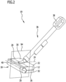
- a holding rod device 36 is pivoted to the cleaning head 12 via a swivel joint.
- the holding rod device 36 is designed in such a way that a standing operator can hold the floor cleaning machine 10 and guide it over the floor 16 to be cleaned.
- a handle 38 is disposed proximally on the support rod assembly 36 .
- the handle 38 is designed as a closed loop handle.
- Other configurations such as a non-closed loop handle and the like are also possible.
- the support rod assembly 36 is pivoted to the base 30 via the pivot joint.
- a pivot axis 40 ( figure 2 ) of the swivel joint of the articulation of the holding rod device 36 to the cleaning head 12 is parallel to the installation surface 14.
- the swivel axis 40 is transverse and in particular perpendicular to the longitudinal axis 24.
- the holding rod device 36 has a (second) longitudinal axis 42 along which the holding rod device 36 extends up to the handle 38 .
- the pivot axis 40 is transverse and in particular perpendicular to this second longitudinal axis 42 of the support rod device 36.
- This rotatability is in figure 1 indicated by the arrow with the reference number 44.
- the corresponding axis of rotation 41 of this rotatability 44 is, for example, parallel or coaxial to a first longitudinal axis 80 of the support rod device 36 (see below).
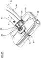
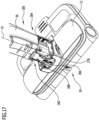
- this rotatability 44 is formed by a corresponding design of the holding rod device 36 with a first part 278 and a second part 280 that can be rotated relative to the first part 278 . This is explained below in particular with reference to Figures 15 to 18 explained in more detail.
- the floor cleaning machine 10 includes a drive motor (in Figs Figures 1 to 3 not shown), by which the cleaning roller unit 18 is driven in rotation about an axis of rotation 46 .
- the cleaning roller unit 18 has a single axis of rotation 46, even if this includes a multi-part cleaning roller.
- the axis of rotation 46 is parallel to the installation surface 14. It is oriented perpendicular to the longitudinal axis 24. It is parallel to the pivot axis 40.
- the pivot axis 40 of the pivotability of the support rod device 36 on the cleaning head 12 and the axis of rotation 46 are coaxial with one another.
- the drive motor is located on the cleaning head 12, or located on the support rod assembly 36, or located at a transition area between the support rod assembly 36 and the cleaning head 12. It acts on the cleaning roller unit 18 and provides a corresponding torque for rotating the cleaning roller unit.
- the floor cleaning machine 10 may be mains powered or battery powered.
- a battery holder 48 which houses one or more batteries, and particularly rechargeable batteries.
- the batteries can be fixed to the floor cleaning machine 10 or be removable from it.
- the battery holder 48 is arranged on the support bar device 36 .
- an arrangement on the cleaning head 12 is also possible.
- the floor cleaning machine 10 is designed in particular for the wet cleaning of hard floors.
- a tank device 50 for cleaning liquid is provided.
- the cleaning liquid is, in particular, fresh water, optionally with the addition of a cleaning agent.
- the cleaning roller unit 18 can be moistened directly and/or the floor 16 to be cleaned can be moistened via cleaning liquid from the tank device 50 . As a result, dirt can be removed in an improved manner, and the corresponding dirty fluid is picked up by the cleaning roller unit 18 and delivered to the dirty fluid tank device 32 .
- the tank device 50 is arranged on the support rod device 36 .
- a corresponding supply device for cleaning liquid is provided, which leads from the tank device 50 to the cleaning head 12 in order to be able to correspondingly moisten the cleaning roller unit 18 and/or the floor 16 to be cleaned with cleaning liquid.
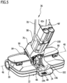
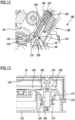
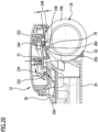
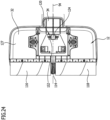
- FIG 3 the basic functional structure of the cleaning head 12 is shown and the basic mode of operation is explained with reference to FIG figure 3 explained.
- the cleaning head 12 is placed with its installation surface 14 on the floor 16 to be cleaned (in figure 3 the at least one further positioning element is not shown).
- the cleaning roller unit 18 acts on the floor to be cleaned and rotates in a direction of rotation 52.
- the dirty fluid tank device 32 is seated on the base 30 of the cleaning head 12.
- a mouth device 54 which has a mouth opening 56 is arranged on the cleaning head 12 .
- This orifice 56 is in fluid communication with the dirty fluid tank device 32 or is itself an orifice on the dirty fluid tank device 32 .
- the cleaning roller unit 18 rotates, it is rotated past the orifice 56 .
- the dirty fluid tank device 32 has a floor 58 .
- this floor 58 faces the floor 16 to be cleaned.
- the wall 60 is adapted to the cylindrical shape of the corresponding cleaning roller of the cleaning roller unit 18 .
- the cleaning head 12 has a sweeping element 62 which is used to feed coarse dirt to the cleaning roller unit 18 .
- This coarse dirt is in figure 3 indicated by double arrows 64.
- the coarse dirt 64 which is made available to the cleaning roller unit 18 via the sweeping element 62 can be taken along by the cleaning roller unit 18 and thrown into the dirt fluid tank device 32 via the outlet opening 56 .
- the sweeping element 62 is arranged on the base 30 or, as in FIG figure 3 shown, arranged on the dirty fluid tank device 32 .
- the cleaning roller unit 18 is moistened with cleaning liquid via a supply device 66 for cleaning liquid.
- This humidification is in figure 3 indicated by the wavy arrows with reference numeral 68.
- the moistening takes place downstream of the orifice opening 56 in relation to the direction of rotation 52 .
- a region of the cleaning roller unit 18 which is seated on the floor 16 to be cleaned then, during rotation in the direction of rotation 52 , first passes the orifice 56 and then the corresponding region with the moistening 68 .
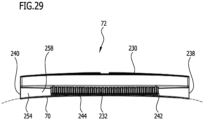
- At least one stripping element 70 is provided, which is arranged on the base 30 and is positioned between the orifice opening 56 and the area of humidification 68 .
- the stripping element 70 is movably positioned on the base 30 .
- the stripping element 70 is seated on a holder 72 which is articulated pivotably on the base 30 .
- This holder 72 is spring-loaded (in figure 3 Not shown). The spring loading presses the stripping element 70 against the cleaning roller unit 18.
- the cleaning roller unit 18 has an attachment which is arranged on a corresponding attachment holder.
- the trimming is a textile material, for example. In principle, however, it can also be a bristle trimming.
- the stripping element 70 is arranged in such a way that it touches the trimming and preferably dips into the trimming.
- the spring loading of the movable holder 72 accordingly ensures that it is pressed or pressed in.
- the wiping element 70 forms an opening wall of the opening device 54 for the opening 56.
- the wiping element 70 separates the area of moistening 68 from the opening 56.
- the stripping element 70 acts on the cleaning roller unit 18 and on the bristles in such a way that dirty fluid is detached from the corresponding cleaning roller (and in particular moist dirty fluid is detached) and conveyed via the orifice opening 56 into the dirty fluid tank device 32 .
- This dirty fluid 74 detached by the stripping element 70 can also contain coarse dirt particles which were not conveyed directly into the dirty fluid tank device 32 via the outlet opening 56 .
- the floor cleaning machine 10 with the training according figure 3 has a sweeping function, through which coarse dirt (and also dry coarse dirt) can be swept from the floor 16 to be cleaned. It has a wiping function, by means of which the floor 16 to be cleaned can be moistened via the moistening device 68 and wet dirty fluid can be picked up and detached via the stripping element 70 and conveyed into the dirty fluid tank device 32 .
- the cleaning roller unit 18 is positioned on the cleaning head 12 in particular so that it can be replaced. As a result, for example, the cleaning roller unit 18 or a cleaning roller can be cleaned easily. As a result, an adaptation to the special cleaning process is also possible. If, for example, a cleaning roller of the cleaning roller unit 18 has a textile trimming such as a microfiber trimming, wet cleaning and sweeping cleaning can be carried out at the same time. However, it is also possible, for example, for a cleaning roller to be used as the cleaning roller with bristles is used to carry out a pure sweeping process. (Moistening of the cleaning roller unit 18 or the floor 16 to be cleaned is particularly switched off during the pure sweeping process.)
- the dirty fluid tank device 32 in particular with the sweeping element 62 fixed thereto, is arranged floating relative to the base 30 in order, for example, to be able to position the sweeping element 62 in the same position as the cleaning roller unit 18, regardless of the trim length of the cleaning roller unit 18.
- the basic operation of the floor cleaning machine 10, as based on the figure 3 was explained is also possible for a cleaning head 12 without a holding rod device 36 and in particular for a self-propelled and self-steering cleaning machine ("cleaning robot").
- cleaning robot a self-propelled and self-steering cleaning machine
- the battery holder 48 and the tank device for cleaning liquid 50 are then arranged in the cleaning head 12 itself.
- dirty fluid is conveyed via the cleaning roller unit 18 into the dirty fluid tank device 32 without a suction unit.
- the dirty fluid tank device 32 can be removed from the cleaning head 12 for emptying.
- the dirty fluid that is in the dirty fluid tank device 32 it is also possible for the dirty fluid that is in the dirty fluid tank device 32 to be sucked out.
- a corresponding suction unit device and an associated additional dirty fluid tank are arranged on the holding rod device 36 .
- support rod assembly 36 includes a first portion 76 and a second portion 78 .
- the first area 76 is arranged at an angle to the second area 78 .
- the first portion 76 is a distal portion, and the second portion 78 is seated with the handle 38 and thus also the proximal portion.
- a control panel with a plurality of control elements is arranged on the handle 38 or on the second area 78 .
- the tank device 50 for cleaning liquid is arranged on the second area 78 .
- control panel includes a switch that can be used to switch whether the cleaning roller unit 18 and/or the floor 16 to be cleaned is moistened with cleaning liquid from the tank device 50 for cleaning liquid 50 .
- this makes it possible to carry out a dry sweeping operation or a wet mopping operation.
- the first region 76 extends in a first longitudinal axis 80 (also compare figure 1 ), and the second portion 78 along the second longitudinal axis 42.
- the first portion 76 and the second portion 78 are at an obtuse angle 82 ( figure 1 ) to each other, which is in the range between 120° and 170°.
- this obtuse angle 82 is approximately 145°.
- the first area 76 and the second area 78 are continuously connected to each other.
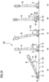
- the support rod device 36 is articulated to the cleaning head 12 and thereby to the base 30 by means of a pivot joint 84 via the first region 76 .
- the pivot axis 40 of the pivot joint 84 coincides with the axis of rotation 46 of rotation of the cleaning roller assembly 18 .
- the swivel joint 84 is designed as an orbital joint. It comprises a web guiding device 86 which is seated on the cleaning head 12 and on the base 30 in a rotationally fixed manner. This path guiding device 86 comprises a circular path section 88. A center of the circular path section 88 lies on the pivot axis 40/rotational axis 46.
- a counter-device 90 which is supported on the web-guiding device 86 , is connected to the first region 76 in a rotationally fixed manner.
- the counter-device 90 is slidably guided on the circular path section 88 of the path-guiding device 86; there is an orbital guidance of the counter-device 90 on the circular path section 88 of the path-guiding device 86 .
- At least three support points are provided for guiding the opposing device 90 on the web guiding device 86 .
- the circular path section 88 is arranged with a partial area behind the cleaning roller unit 18 in relation to the longitudinal axis 24 of the cleaning head 12 . Relative to a height axis 92, which is perpendicular to the longitudinal axis 24 and perpendicular to the installation surface 14, the circular path section 88 is arranged with a partial area above the cleaning roller unit 18.
- the circular path section 88 is designed, for example, at least approximately as a quadrant section, which to a certain extent encompasses the cleaning roller unit 18 .
- the pivot joint is positioned midway between the first lateral side 26 and the second lateral side 28 on the base 30 . In particular, it is arranged symmetrically on the cleaning head 12 . It lies on a median plane 94 (cf figure 2 ), which is located centrally between the first lateral side 26 and the second lateral side 28 and is oriented perpendicularly to the axis of rotation 46 or pivot axis 40 .
- the center plane 94 is also oriented perpendicular to the installation area 14 .
- a drive motor 98 which is in particular an electric motor, is provided for driving the cleaning roller unit 18 in the rotational movement of the axis of rotation 46 with the direction of rotation 52.
- This is non-rotatably connected to the support rod device 36 so that it is also pivoted about the pivot axis 40 during a pivoting movement of the support rod device 36 .
- the drive motor 98 is positioned on the support rod assembly 36 and is particularly positioned on the first portion 76 .
- the first portion 76 of the support rod assembly 36 includes a housing 100 that houses the drive motor 98 .
- a battery holder 48 ′ is arranged on the first area 76 or on a transition between the first area 76 and the second area 78 . (In the case of the figures 1 and 2 shown embodiment, the battery holder 48 is arranged on the second area 78.)
- a free space 102 (cf figure 5 ) formed midway between first lateral side 26 and second lateral side 28 and lying at midplane 94 .
- This free space 102 forms a pivoting space in which the holding rod device 36 can be moved, with the first area 76 then being able to be moved in this free space 102 in particular.
- the clearance 102 is open to the rear end 22 .
- the housing 100 with the drive motor 98 can be moved in the free space 102 .
- the free space 102 results in a large pivoting angle range for the pivotability of the support rod device 36 about the pivot axis 40 relative to the base 30.
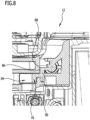
- the floor cleaning machine 10 has a transmission device 104 ( figure 7 ), which serves to transmit a torque from the drive motor 98, which is positioned at a distance from the cleaning roller unit 18, to the cleaning roller unit 18.
- the transmission device 104 also includes a reduction gear, which is used to reduce the speed, so that a speed of the cleaning roller unit 18 when rotating about the axis of rotation 46 is lower than a drive speed of the drive motor 98.
- the transmission device 104 includes, for example, a belt transmission and the speed reduction gear.
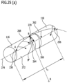
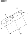
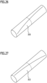
- the cleaning roller unit 18 is or includes a roller mount 106.
- the roller mount 106 in turn includes a shaft 108 which is connected to the transmission device 104 in a torque-effective manner.
- the shaft 108 rotates about the axis of rotation 46 when driven accordingly by the drive motor 98.
- the shaft 108 (cf figure 6 ) a first shaft portion 110, a second shaft portion 112 and a middle portion 114 which is connected to the first shaft portion 110 and the second shaft portion 112.
- the shaft 108 with the first shaft part 110, the second shaft part 112 and the middle part 114 forms a unitary shaft with a single axis of rotation, namely the axis of rotation 46.
- the middle part 114 lies centrally between the first lateral side 26 and the second lateral side 28 and lies at the middle plane 94.
- the first shaft portion 110 receives a first roller portion 116 and the second shaft portion 112 receives a second roller portion 118 of the cleaning roller unit 18.
- the first barrel portion 116 and the second barrel portion 118 are separate units, but rotate about the same axis of rotation 46 when seated on the shaft 108 .
- the first roller portion 116 which is seated on the first shaft portion 110, extends to the first lateral side 26, or almost to it.
- the second roller portion 118 which is seated on the second shaft portion 112, extends to the second lateral side 28, or almost to it.
- the central portion 114 of the shaft 108 is roller-free.
- the transmission device 104 is coupled to it in a torque-effective manner. There is a center drive of the cleaning roller unit 18 .
- the first roller part 116 and the second roller part 118 are each pushed onto the associated shaft part 110 or 112 from the outside and latched accordingly with the associated shaft part 110 or 112 in order to obtain a non-rotatable connection.
- the central part 114 of the shaft 108 and thus the roller mount 106 and the swivel joint 84 are aligned. They lie on the center plane 94 and are in particular each formed mirror-symmetrically to the center plane 94 .
- the cleaning head 12 has (at least) one support element 120 .
- exactly one support element 120 is provided ( figure 7 , Figure 19(d) , figure 23 , 24 ).
- the support element 120 sits at a distance from the cleaning roller unit 18 and defines the installation surface 14 with it.
- the support element 120 sits on the base 30. Even if the dirty fluid tank device 32 is removed, the cleaning head 12 with the cleaning roller unit 18 and the support element 120 can be placed on a floor 16 to be set up.
- the support member 120 includes a post 122 on which a roller or slider 124 is seated.
- the roller or the slider 124 is used for support on the floor 16 to be cleaned.
- the roller or the slider 124 for example a skid being provided, is guided over the floor 16 to be cleaned when the floor cleaning machine 10 is guided.
- the base 30 has an underside 126 facing the dirty fluid tank device 32 .
- the post 122 projects transversely and in particular perpendicularly from this underside 126 in the direction of the installation surface 14 .
- the support element 120 lies on the center plane 94.
- the shape and dimensions of the dirty fluid tank device 32 are adapted to the base 30 .
- the dirty fluid tank device 32 has a bottom 127 and a top 128 .
- the top 128 of the dirty fluid tank device 32 faces the bottom 126 of the base 30 .
- the bottom 127 of the dirty fluid tank device 32 lies on the bottom 58 and faces away from the top 128 .
- the wall 60 and another wall 130 which closes the dirty fluid tank device 32 with an interior space for receiving dirty fluid.
- the wall 60 of the dirty fluid tank device 32, on which the orifice 56 is seated, has a cutout 132 (cf figure 6 ) which is fitted to the center portion 114 of the shaft 108.
- the central portion 114 is at least partially seated within the cutout 132 of the dirty fluid tank assembly 32 with free rotation.
- the mouth opening 56 of the mouth device 54 comprises, in particular, a first opening part 134 and a second opening part 136.
- the first opening part 134 is associated with the first roller part 116 and the second opening part 136 is associated with the second roller part 118 .
- the dirty fluid tank device 32 has a first chamber 138 and a second chamber 140 .
- the first opening part 134 is formed and on the second chamber 140 the second opening part 136 is formed. Dirty fluid is coupled directly into the first chamber 138 via the first opening portion 134 and dirty fluid is coupled directly into the second chamber 140 via the second opening portion 136 .
- the two chambers 138 and 140 can be separated from one another in a fluid-tight manner or can be fluidly connected to one another, so that dirty fluid can be evenly distributed in the dirty fluid tank device 32 .
- the dirty fluid tank device 32 has a cover 142 which at least partially forms the upper side 128 .
- This cover 142 is at a distance from the base 58.
- the cover 142 can be removed when the dirty fluid tank device 32 has been removed from the cleaning head 12 in order to be able to empty the dirty fluid tank device 32 .
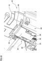
- the kick tab 34 is arranged on the wall 130 of the dirty fluid tank device 32 . It is arranged in such a way that, when the dirty fluid tank device 32 is fixed to the base 30 , it is at a distance from the installation surface 14 .
- the kick tab 34 is arranged in alignment with the free space 102 . It is a continuation of the space 102 from the rear end 22 away. It is arranged in such a way that it does not impede the corresponding pivoting space of the holding rod device 36 in the free space 102 .
- the step strap 34 is located on the center plane 94 and is in particular arranged and formed mirror-symmetrically to this.
- the kick strap 34 includes a panel 144 having raised edge walls 146 (see FIG figure 5 ).
- the edge walls 146 are rounded in this case.
- the kick strap 34 has a width (in a direction parallel to the pivot axis 40 or rotation axis 46) which is at least as wide as typical dimensions of a foot with shoes.
- An operator may place his foot on the step tab 34 and then, by applying appropriate force, lift the cleaning head 12 to detach the dirty fluid tank assembly 32 from the base 30 . This is described in more detail below.
- the raised, rounded edge walls 146 of the step strap 134 prevent an operator's foot from slipping off to the side. Sharp edges on the plate 144 are avoided.
- spaced webs or grooves are arranged on the plate 144, which are intended to prevent an operator's foot from slipping off.
- the step strap 34 is arranged in alignment as a continuation of the free space 102 . It is aligned in relation to the longitudinal axis 24 of the cleaning head 12 with the swivel joint 84 and also aligned with the central part 114 of the shaft 108 .
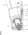
- the dirty fluid tank device 32 has a removal direction 148 ( figure 6 ) away from base 30.
- the removal direction 148 leads away from the underside 126 of the base 30 in the direction of the installation surface 14.
- the dirty fluid tank device 32 can be removed from the cleaning head 12 in such a way that, for example, by lifting the cleaning head 12 and Pressing the dirty fluid tank device 32 (e.g. on the step tab 34) in the direction of the removal direction 148, or by pulling the dirty fluid tank device 32 away from the base 30 in the removal direction 148 and can thus be removed.
- a space 150 is formed in the cleaning head 12, delimited by the underside 126 of the base 30, in which the dirty fluid tank device 32 is positioned when it is fixed to the base 30.
- the support element 120 is also located in this space.
- a continuous recess 152 ( figures 7 , 19(d) , 24 ) educated. This continuous recess 152 is open at the top 128 and at the bottom 127 . The continuous recess 152 is closed at the side, so that it is closed in a fluid-tight manner.
- the support element 120 When the dirty fluid tank device 32 is seated on the base 30, the support element 120 is immersed through the continuous recess 152, so that the cleaning head 12 can be supported via the support element 120 on the floor 16 to be cleaned.
- the continuous recess 152 is dimensioned in such a way that the support element 120 can penetrate through and correspondingly also emerge when the dirty fluid tank device 32 is removed from the base 30 .
- the continuous recess 152 is closed on all sides.
- the continuous recess 152 it is also possible for the continuous recess 152 to be open towards the rear end 22 .
- the continuous recess 152 has the shape of a (hollow) cylinder.
- the continuous recess 152 is arranged in line with the central part 114 of the shaft 108, the pivot joint 84 and the foot strap 34, corresponding to the aligned orientation of the support element 120 in relation to the longitudinal axis 24.
- the dirty fluid tank assembly 32 is suspended from the base 30 .
- a plurality of holders 154 (cf figures 11 and 13 ) provided, which sit on the base 30 and protrude from the underside 126 away in the direction of the installation surface 14.
- a first bracket and a second spaced bracket are provided. These are designed as described below and, in particular, are designed in the same way.
- the first holder and the second holder are preferably arranged mirror-symmetrically to the center plane 94 and the free space 102 lies between them.
- a first location 156 is indicated at which the first holder sits, and a second location 158 is indicated at which the second holder sits. As mentioned, these are the attachment points for the dirty fluid tank device 32 on the base 30.
- the holders 154 are designed as holding domes or holding mushrooms.
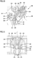
- the holder 154 and the associated receptacle 160 form a holder-receptacle combination 162, which is designed as a snap-in connection device.
- a corresponding holding position or locking position is shown.
- the holder 154 includes a first element 164 which corresponds to a second element 166 of the receptacle 160 on the dirty fluid tank device 32 .
- the first element 164 has a receiving area 168 for the second element 166.
- This receiving area 168 is, for example, cylindrical.
- the receiving area 168 of the first element 164 is delimited by a bead 170 .
- the bead 170 has a diameter (in a direction transverse to the elevation axis 92) which is larger than the corresponding diameter of the receiving area 168.
- the ridge 170 is disposed on the first member 164 as an annular region. It has a first surface area 172 which faces the receiving area 168 . A second surface area 174 , which faces away from the receiving area 168 , adjoins the first surface area 172 .
- the bead 170 is tapered at the first surface area 172 away from the receiving area 168 . It is on the second surface area 174 likewise conical with a slope towards the receiving area 168 .
- An inclined plane is formed by the first surface region 172 which, as will be explained in more detail below, requires an application of force in order to detach the second element 166 from the first element 164 .
- An inclined plane is also formed by the second surface area 174 , which requires an expenditure of force in order to connect the second element 166 to the first element 164 .
- the cone angle of the first surface portion 172 is greater than the cone angle of the second surface portion 174 (cf figure 11 ).
- the first cone angle for the first surface area 172 is denoted by the reference number 176 there.
- the second cone angle for the second surface area 174 is denoted by 178 .
- the second cone angle 178 is smaller than the first cone angle 176. This means that the force required to loosen and remove the dirty fluid tank device 32 from the base 30 is greater than to insert (for fixing) the dirty fluid tank device 32 to the base 30.
- the second element 166 on the receptacle 160 of the dirty fluid tank device 32 is designed as a spreading element which has at least two and preferably at least three tabs which can be moved transversely to the vertical axis 92 (increasing the distance).
- the second element 166 as a spreading element is pushed onto the holder 154 .
- the second element 166 of the second surface area 174 is spread apart, increasing the distance between the tabs, until the receptacle area 168 is reached.
- the tabs of the spreading element 166 are arranged in particular in a resilient manner and snap back.
- the bead 170 serves as a barrier which prevents the dirty fluid tank assembly 32 from falling off the base 30 .
- a latching connection is established via the holder-receiving combination 162 .
- an operator exerts force on the dirty fluid tank device 32 and moves the second element (the spreader element) over the bead 170 and thereby over the first surface area 172.
- a corresponding amount of force is required to spread the second element 166 (the spreader element) open. necessary to expand the cross section accordingly so that the bead 170 can be traversed by the second element 166.
- a corresponding intermediate state after being run over is in figure 13 shown. There the locking connection is canceled.
- the spreading element 166 (the second element 166) has passed the bead 170 and is outside the receiving area 168.
- the receptacles 160 on the dirty fluid tank device 32 are open at the top 128 in order to allow the corresponding holder 154 to be immersed.
- the receptacle has an extension 180 in the shape of a hollow truncated cone towards the upper side 128 .
- This extension 180 forms an insertion and centering aid for the holder 154, which is in the form of a pin, in the associated receptacle 160.
- the dirty fluid tank assembly 32 When the dirty fluid tank assembly 32 is held on the base 30 via the holder-receiver combination 162 (at locations 156, 158), then the dirty fluid tank assembly 32 is movably mounted (in a direction/opposite direction parallel to the elevation axis 92) and is thereby supported in a floating manner .
- the weight of the floor cleaning machine 10 is supported on the floor 16 to be cleaned via the cleaning roller unit 18 and the support element 120 .
- the dirty fluid tank device 32 has no support function in this regard.
- the dirty fluid tank device 32 is movably mounted (floating) transversely and in particular perpendicularly to the installation surface 14 .
- the sweeping element 62 is still in its optimal position relative to the floor 16 to be cleaned.
- the holding rod device 36 has a pivot angle range of pivot mobility relative to the cleaning head 12 which lies between a lower limit and an upper limit.
- a swivel angle 182 (cf Figure 19(a) ) is in particular quantitative as an angle between the second longitudinal axis 42 of the support rod device 36 and a plane 184 parallel to the installation surface 14.
- a minimum pan angle 182, i.e. the lower limit, is 0° or greater than 0°.
- the lower limit is less than 50° and preferably less than 40° and particularly preferably less than 30°.
- the lower limit is determined by the support rod device 36 resting against an underside which encloses the free space 102 (cf figure 9 ) limited, predetermined.
- the lower limit can be approximately 0° and can in particular be less than 10° and preferably less than 5°.
- the swivel angle range has an upper limit ( Figure 19(b) ).
- the upper limit of the swivel angle 182 is specified as the detent position ( figure 19 ). In particular, it is in the range between 80° and 120° of the pivot angle 182. In a preferred exemplary embodiment, it is approximately 90° ( Figure 19(b) ).
- the upper limit is such that a parking position with a latching position with respect to the cleaning head 12 is provided for the holding rod device 36, in which case pivoting with respect to the cleaning head 12 is blocked in the Meaning that an increased expenditure of force is necessary in order to enable pivoting of the holding rod device 36 on the pivot joint 84 about the pivot axis 40 again.
- the holder-receptacle combination 162 has been described as having a holder 154 which is fixedly connected to the base 30 and a receptacle 160 which is arranged on the dirty fluid tank device 32 .
- the holder 154 is rod-shaped and the receptacle 160 is an opening.
- a kinematic reversal is also possible, in which a rod-shaped element is arranged on the dirty fluid tank device 32 and a corresponding receptacle in the form of an opening on the base 30.
- a locking device 186 ( figures 10 , 12 ) intended.
- the locking device 186 comprises one and in particular at least two and preferably exactly two ( figures 10 , 12 ).
- the pin-plunger combinations 188 are located in the area of the pivot joint 84 .
- FIG 9 a first location 190 and a second location 192 are shown at which respective pin-plunger combinations 188 are positioned.
- the first point 190 and the second point 192 are mirror-symmetrical to the center plane 94.
- the pin-immersion opening combination 188 each includes an immersion opening 194 which is arranged on the cleaning head 12 and in particular on the base 30 in a rotationally fixed manner with respect to the web guide device 86 .
- a pin 196 is provided as a counter-element to the corresponding immersion opening 194 and is connected to the holding rod device 36 in a torque-proof manner and can be pivoted with it about the pivot axis 40 relative to the cleaning head 12 .
- the pin 196 is seated on a guide 198 and is linearly translatable along a translation axis 200.
- the translation axis 200 is movable with the pivotal movement of the support rod assembly 36 relative to the cleaning head 12. It is oriented transversely to a circumference of circular path section 88 .
- the pin 196 is spring-loaded via a spring device 202, with a spring force of the spring device 202 tending to press the pin 196 in the direction of the circumference of the circular path section 88.
- the spring force of the spring device 202 acts on the cleaning head 12 .
- the pin 196 has a ridge 204 ( figure 10 ), which is arranged in a ring.
- the guide 198 has an annular stop 206 for the bead 204 .
- a stop for the linear displaceability of the pin 196 on the guide 198 is formed by the bead 204 resting against the stop 206 ( figure 10 ).
- a basic position of the pin 196 is such that the spring device 202 presses the pin 196 to the circumference of the circular path section 88 until the bead 204 rests against the stop 206 ( figure 10 ). This basic position is present when the pin 196 has not entered the immersion opening 194 .
- the basic position is in turn present when the parking position 185 of the holding rod device 36 and the cleaning head 12 has not been reached, ie when the upper limit of the pivoting angle 182 has not been reached. See figure 10 , wherein the pin 196 is not immersed in the immersion hole 194.
- the respective immersion opening 194 is formed on a block element 208 .
- the block element 208 includes the immersion opening 194 as a recess or drilling.
- a first inclined plane 210 is arranged or formed on the block element 208 outside the immersion opening 194 . This rises from the circular path section 88 . It is located at the end of the circular path section 88 and at the first inclined plane 210 the distance to the pivot axis 40 increases.
- the first inclined plane 210 is used to insert the pin 196 into the immersion opening 194 while displacing the pin 196 away from the stop 206 with a corresponding exertion of force against the spring force of the spring device 202 . This effort must be applied by an operator.
- the pin 196 has a first contact surface 212 which is formed on a front end of the pin 196 .
- the first contact surface 212 is adapted to the first inclined plane 210 .
- the immersion opening 194 formed in the block element 208 has a wall formed as a second inclined plane 214 .
- the pin 196 is guided along the circular path section 88 while increasing the pivoting angle 182 and then over the first inclined plane 210 into the immersion opening 194.
- the second inclined plane 214 serves to guide the pin 196 out of the immersion opening 194 by reducing the pivoting angle 182 starting from the upper limit.
- the pin 196 has a second contact surface 216 which is adapted to the second inclined plane 214 .
- the second contact surface 216 is guided in contact with the second inclined plane 214 along the second inclined plane 214 (with the pivoting angle 182 being reduced). To do this, the spring force of the spring device 202 must be overcome.
- the first incline 210 has a smaller angle than the second incline 214.
- the force required to release the latch by extending the pin 196 out of the plunger opening 194 is greater than the force required , in order to bring the pin 196 into the immersion opening 194 via the second inclined plane 214 and to establish the locking and thereby to reach the parking position 185.
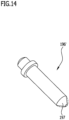
- An alternate embodiment of a pin 196' ( figure 14 ) has a contact surface 197 at a tip, which is conical.
- the pin is spherically shaped at the tip (in figure 14 indicated in broken lines).
- the pin 196 or the pin 196' is made in particular from a metallic material.
- a tip 218 preferably rests on this circular path section 88 between the first contact surface 212 and the second contact surface 216 .
- a circular path section 88 is also possible for a circular path section 88 to be provided which is separate from this circular path section 88 for the counter-device 90 but is concentric with the pivot axis 40 .
- an operator can, by exerting a correspondingly large amount of force by exerting a torque on the holding rod device 36 in the direction of the floor 16 to be cleaned, on which the floor cleaning machine 10 is properly positioned via the cleaning head 12, cancel the locking and remove the corresponding pin 196 from the Immersion opening 194 lead. It is then possible to pivot freely up to the lower limit.
- an operator pivots the holding rod device 36 about the pivot axis 40 towards the parking position 185 until the parking position 185 is reached by locking the pin 196 into the associated immersion opening 194 is.
- an intermediate position is shown shortly before reaching the locked position.
- FIG 19(a) a "work" pivot position is shown.
- the pivot angle 182 is between the lower limit and the upper limit.
- the floor 16 to be cleaned can be worked on by the floor cleaning machine 10 in order to carry out a cleaning process.
- An operator adapts the swivel angle 182 to his height. If a piece of furniture or the like is to be driven under, the pivoting angle 182 is reduced.
- the operator guides the cleaning head 12 over the floor 16 to be cleaned using the holding rod device 36 with the adjusted swivel angle 182.
- the cleaning roller unit 18 rotates about the axis of rotation 46. Due to the direction of rotation 52, the cleaning head 12 and thus the floor cleaning machine 10 experience a propulsion.
- the support rod device 36 is connected directly to the roller mount 106 and thus to the cleaning roller unit 18 .
- the cleaning roller unit 18 With a pivoting movement of the holding rod device 36 about the pivot axis 40, the cleaning roller unit 18 is also pivoted. If this is supported on the floor 16 to be cleaned, then it rolls off on the floor 16 . This movement is superimposed on the rotation of the cleaning roller unit 18 about the axis of rotation 46 and has no negative effect on the cleaning result or the like. Due to the rotation of the cleaning roller unit 18, the angular range through which the cleaning roller unit 18 runs in the same time unit as during a pivoting movement is very much larger.
- the support rod device 36 is directly connected to the cleaning roller unit 18 and its weight acts directly on the cleaning roller unit 18.
- the weight of the support rod device 36 presses the cleaning roller unit 18 with the roller parts 116, 118 against the floor 16 to be cleaned.
- the support rod device 36 acts by its own weight a pressing force of the cleaning roller unit 18 on the floor 16 to be cleaned. This improves the cleaning effect; the mechanical action of the cleaning roller unit 18 on the floor 16 to be cleaned is improved.
- the ability of the floor cleaning machine 10 to remove dirt is improved.
- the described design of the swivel joint 84 as an orbital swivel joint results in a large swivel range between the lower limit and the upper limit.
- the operator increases the swivel angle 182 until the parking position 185 is reached ( Figure 19(b) ) and the retaining rod device 36 is locked to the cleaning head 12 via the locking device 186 .
- the support rod device 36 cannot “fall down” of its own accord (because of its own weight), with the pivoting angle 182 decreasing in the direction of the lower limit.
- the floor cleaning machine 10 is parked, for example for storage.
- a corresponding cleaning station or parking station (not shown in the figures).
- the dirty fluid tank device 32 can also be emptied in the ground station.
- the dirty fluid tank device 32 can also be easily removed from the cleaning head 12 ( figure 19(c),(d) ).
- This torque application occurs in the park position 185 where the support rod assembly 36 is locked to the base 30 by the latch assembly 186 . If necessary, the pivoting angle 182 can be increased somewhat by providing play in the play/immersion opening combinations 188 . When this play is exhausted, the cleaning head 12, which is then in particular still supported on the floor 16 via the cleaning roller unit 18, rotates relative to the dirty fluid tank device 32.
- the base 30 is raised relative to the dirty fluid tank device 32.
- the dirty fluid tank device 32 remains on the floor 16 as a result of the operator intervention on the foot strap 34 .
- An operator has fixed the dirty fluid tank device 32 on the floor 16 via the force 220 .
- the cleaning head 12 it is also possible for the cleaning head 12 to be removed from the dirty fluid tank device 32 by pulling it upwards, with an operator fixing the dirty fluid tank device 32 to the floor 16 by exerting force on the foot strap 34 .
- Figure 1 shows a situation which arises after the dirty fluid tank assembly 32 has been detached from the cleaning head 12, either by pivotal lifting or by pulling straight up.
- the cleaning head 12 in the support rod assembly 36 is finally removed from the dirty fluid tank assembly 32 .
- FIG 19(e) a situation is shown in which the cleaning head 12 is placed back onto the dirty fluid tank device 32, that is to say in which the dirty fluid tank device 32 is fixed to the cleaning head 12.
- the dirty fluid tank device 32 is placed on the floor 16 . If necessary, an operator fixes the dirty fluid tank device 32 to the floor 16 by exerting force on the foot strap 34.
- the cleaning head 12 is then placed from above onto the dirty fluid tank device 32 in such a way that the corresponding holder 154 is immersed in the associated receptacle 60 on the dirty fluid tank device 32 until it latches (and then correspondingly the respective second element 166 in the associated receiving area 168 of the first element 164).
- the cleaning head 12 is preferably set down with the holding rod device 36 in a parking position 185 relative to the cleaning head 12, i.e. with the holding rod device 36 being locked on the cleaning head 12 by the locking device 186.
- the corresponding design of the first surface area 172 and the second surface area 14 preferably requires a greater force to remove the dirty fluid tank device 32 from the cleaning head 12 ( Figures 19(c) and (d) ) necessary than for fixing ( Figure 19(e) ).
- an operator can remove the dirty fluid tank device 32 from the cleaning head 12 and insert the dirty fluid tank device 32 in the cleaning head 12 hands-free, i.e. he does not have to touch the dirty fluid tank device 32 for this purpose.
- he can carry out the corresponding processes by grasping and holding the holding rod device 36 . He doesn't have to bend down or bend his knees.
- the stripping element 70 is movably arranged on the cleaning head 12 and on the base 30 via the holder 72 .
- the holder 72 has a base 222 .
- the base 222 has a rear end 224 and a front end 226.
- the base 222 is wider toward the front end 226 than at the rear end 224; the base 222 has a first portion 228 and a second portion 230, with the first portion 228 having the rear end 224 and the second portion 230 having the front end 226.
- the holder 72 is held pivotably on the base 30 of the cleaning head 2 via the first area 228 .
- the second area 230 carries the stripping element 70 and a comb element 232.
- stub shafts 234 Arranged on the first region 228 are stub shafts 234 which protrude laterally outwards. Shaft stubs 234 are provided opposite one another and are aligned in alignment. A pivot axis 236 is defined by the stub shafts 234 . When the holder 72 is fixed to the base 30, the pivot axis 236 is parallel to the pivot axis 40 or parallel to the axis of rotation 46. It is parallel to the installation surface 14.
- the cleaning roller unit 18 there is provision for the cleaning roller unit 18 to have a continuous stripping element 70 which acts both on the first roller part 116 and on the second roller part 118 ( Figure 25(a) ). In particular, no recess or the like is provided for the central part 114 .
- the stripping element 70 extends continuously between a first front end 238 and an opposite second front end 240.
- the stripping element 70 is arranged or formed as a web on the second region 230 .
- this web is integrally connected to the second region 230, that is, integrally connected to the holder 72.
- the comb element 232 is also seated on the holder 72. It acts on the cleaning roller unit 18 and serves to collect hair; the comb element 232 is a hair comb.
- the comb element 232 includes at least one row 242 and in particular a plurality of rows 242 of pins 244. Adjacent pins 244 are spaced apart from one another. A pin dips into a trimming 246 (compare, for example figure 20 ) of the cleaning roller unit 18 to a certain extent "filter out” hair from the cleaning roller unit 18.
- the comb element 232 is arranged downstream of the stripping element 70 .
- a portion of the cleaning roller unit 18 which rotates in the direction of rotation 52 starting from the base 16 first passes the stripping element 70 and then the comb element 232 . This results in a space-optimized arrangement.
- the comb element 232 (rows 242) are arranged on the second region 230 between the front end 226 and the stripping element 70 (cf figure 30 ).
- the comb element 232 extends over a smaller transverse length than the stripping element 70, i.e. a distance between the outer ends of the comb element 232 is smaller than a distance between the front ends 238 and 240 of the stripping element 70 ( figure 30 ).
- the holder 72 is pivotally supported on the base 30 . It is spring-loaded in order to press the stripping element 70 and the comb element 232 into the trimming 246 .
- a corresponding spring device is provided, which is arranged, for example, in the area of the shaft stub 234 on the corresponding pivot bearing 250 . this is in figure 20 indicated by reference numeral 252.
- a corresponding spiral spring of the spring device is supported on the base 30 and on the second area of the holder 72 in order to press it against the cleaning roller unit 18 .
- the stripping element 70 is arranged as a web 254 on the second area 30 .
- This web 254 has a first flank 256 which faces the mouth opening 56 . It has an opposite second flank 258 which faces away from the mouth opening 56 ( figure 20 ).
- the second flank 258 faces the comb element 232 .
- An edge 260 lies between the first flank 256 and the second flank 258.
- a contact line 262 ( figure 25 ) educated. This corresponds to the course of the edge and can be described by a mathematical curve.
- the web 254 of the stripping element 70 has a triangular shape across the first flank 256 and the second flank 258 (cf figure 20 ).
- the contact line 262 has a finite width.
- the contact line 262 is in the stocking 246 (compare figure 20 ) or at least rests against the trimming 246. Via the contact line 262, the stripping element 70 rests on or dips into the trimming 246.
- the stripping element 70 is designed as a guide element for dirty fluid on the cleaning roller unit 18 .
- the training is in one embodiment ( Figure 25(a) ) Such that dirty fluid over the scraper 70 not only is detached from the cleaning roller unit 18 (from the facing 246), but is also guided in a defined manner to a middle region 264.
- This middle area 264 lies on the cleaning roller unit 18 and on the scraper element 70 .
- dirt fluid (to a large extent) is coupled into the orifice opening 56 .
- the central area 264 lies at the central plane 94.
- the stripping element 70 is curved.
- the line of contact 262 has a first length L 1 (arc length) between the first front end 238 and the second front end 240 .
- a distance D between the first front end 238 and the second front end 240, a distance direction for the distance D being parallel to the pivot axis 236 or parallel to the pivot axis 40 or parallel to the rotation axis 46, is smaller than this length L 1 .
- the cleaning roller unit 18 (as a combination of the first cleaning roller 116 and the second cleaning roller 118 with spacing in between) has a second length in the spacing direction (i.e. parallel to the axis of rotation 46).
- L 2 on (compare figure 4 ), which is smaller than the length L 1 .
- the curvature of the stripping element 70 at the contact line 262 can be two-dimensional or three-dimensional in the sense that a mathematical curve that describes the course of the contact line 262 and is a curved curve can be a flat curve (two-dimensional curvature) or a space curve (three-dimensional curvature) can be.
- the corresponding curve which mathematically describes the course of the contact line 262
- has a first curvature in the sense of a differential geometric curvature
- the first curvature is negative, ie the corresponding mathematical curve describing the course of the contact line 262 is concave, or the first curvature and the second curvature are both negative and the corresponding curve is a concave curve.
- a discharge area for dirty fluid from the cleaning roller unit 18 into the dirty fluid tank device 32 is formed by the mouth device 54 .
- the contact line 262 is concave towards this dispensing area, ie towards the mouth opening 56 . This concave formation is on the first flank 256.
- a convex configuration is present on the second flank 258, ie facing away from the dispensing area (the orifice opening 56).
- a corresponding concave area 266 and a convex area 268 are shown in FIG figure 25 shown.
- the line of contact 262 has the shape of a segment of a circular arc.
- the corresponding mathematical curve which describes the course of the contact line 262, has a constant curvature.
- a first curvature can be provided, which is constant, and if the contact line 262 can be described by a space curve, a constant second curvature can be present.
- a radius of curvature R lies in the range between 2L 2 and 6L 2 (2L 2 ⁇ R ⁇ 6L 2 ).
- the stripping element 70 has an apex 270 across the contact line 262, which in one embodiment (cf. Figure 25(a) ) is located at the center plane 94.
- the course of the mathematical curve, which describes the course of the contact line 262, can be described in cylindrical coordinates.
- a projection of the contact line 262 onto an (imaginary) cylinder 272 ( Figure 25(a) ) with a cylinder axis 274 can be considered.
- the contact line 262 is related to the vertex 270 or the center plane 94 mirror-symmetrical ( Figure 25(a) ).
- a polar angle ⁇ varies along the course of the curve.
- figure 21 12 is a section through the cleaning head 12 at point A according to FIG figure 25 shown, and in figure 22 a cut at point B (i.e., at vertex 270).
- the cleaning roller unit 18 there is a guide area on the surface of the cleaning roller unit 18 and also in a penetration area of the scraping element 70 due to the curvature of the scraping element 70 for dirty fluid, via which dirty fluid on the cleaning roller unit 18 is conducted to the central area 264 by means of the stripping element 70 .
- the discharge area can be made smaller in relation to the distance direction parallel to the axis of rotation 46, i.e. the orifice opening 56 can be made with a smaller length L 3 than, for example, with a straight scraping element 70.
- a smaller transfer area for dirty fluid to the dirty fluid tank device 32 can thereby be implemented . Dirty fluid delivery is simplified and device contamination is reduced.
- any foam that occurs on the cleaning roller unit 18 is guided to the middle region 264 by the scraper element 70 .
- the emergence of foam at the front ends of the cleaning roller unit 18 is reduced or at least greatly reduced.
- a stripping element 70 was described, which is assigned to the cleaning roller unit 18 with the first roller part 116 and the second roller part 118 and in which the apex 270 is arranged on a central plane.
- FIG 25(b) an alternative exemplary embodiment is shown with a stripping element which is not designed to be continuous.
- Each roller part 116 or 118 is assigned its own stripping element, with these stripping elements in particular being arranged on a single holder (the holder 72).
- FIG 25 a contact line 262' for the exemplary case of the first roller part 116 is shown.
- the first roller part has a length L 2 ⁇ .
- This length L 2 * lies between the corresponding end faces of the first roller part 116 (or of the second roller part 118).
- the corresponding edge element has edge progression 262' which is symmetrical.
- the corresponding stripping element which is assigned to the first roller part 116 (or the second roller part 118), is curved in a circular shape, with a radius of curvature R* lying in particular in the range between 2L 2 ⁇ and 6L 2 ⁇ (2L 2 ⁇ ⁇ R* ⁇ 6L 2 ⁇ ).
- the combination of scraping elements has a "double hump" shape, in which combination the respective scraping elements can then be spaced or continuous.
- the corresponding curved profile of the stripping element 70 is asymmetrical and has no apex or no apex at a midplane.
- a targeted drainage of dirty fluid to one side 310 ( figure 26 ) or to a page 312 ( figure 27 ) take place.
- the course is as shown in FIG Figures 26 or 27 asymmetrical. If, for example, for the first roller part 116 according to the course figure 26 is present and for the second roller part 118 the course according to figure 27 , the overall profile is symmetrical in relation to the cleaning roller unit 18 with the first roller part 116 and the second roller part 118 . In this embodiment, in particular, there is a derivation to the outside.
- the embodiment of the curved stripping element is also possible if the cleaning roller unit has only one roller part.
- the configuration of the stripping element 70 with a curvature has been described with reference to the floor cleaning machine 10 .
- This solution of the curved design can also be used on other types of surface cleaning machines, such as on a self-propelled and self-steering cleaning machine (cleaning robot).
- the floor cleaning machine 10 works as follows: For a cleaning operation, the cleaning head 12 is set up on the floor 16 to be cleaned. An operator guides the cleaning head 12 over the holding bar device 36 over the floor 16 to be cleaned.
- cleaning fluid is supplied from the tank device 50 for cleaning fluid, in particular to the cleaning roller unit 18.
- the floor 16 to be cleaned is thereby moistened for better dirt removal. Dirt is taken along and transported to the stripping element 70 via the cleaning roller unit 18 . Dirty fluid, which is then in particular liquid with dirt particles, is detached from the cleaning roller unit 18 and conveyed into the dirty fluid tank device 32 .
- the guiding element function of the stripping element 70 due to the corresponding curvature results in a simplified discharge of dirty fluid.
- Coarse dirt can also be picked up.
- the sweeping element 62 ensures that coarse dirt is fed to the cleaning roller unit 18. This transports the coarse dirt directly into the dirt fluid tank device 32 and/or it is detached via the stripping element 70.
- Hair is removed from the cleaning roller unit 18 via the comb element 232 .
- the cleaning roller unit 18, in which the covering 246 is a textile material, is used in particular for a wet cleaning operation.
- the cleaning roller unit 18 can also be used for a sweeping operation.
- the cleaning roller unit 18 it is also possible, for example for a sweeping process, for the cleaning roller unit 18 to be exchanged and a cleaning roller unit to be used in which the trimmings are bristles.
- the floor-cleaning machine 10 allows for a purely dry cleaning or a wet cleaning, as required.
- the holding rod device 36 is supported on the cleaning roller unit 18 by the orbital joint 84 and a corresponding pressing force is exerted on the floor 16 to be cleaned.
- a corresponding pressing force is exerted on the floor 16 to be cleaned.
- the cleaning roller unit 18 experiences a maximum contact pressure via the holding rod device 36 via the floor cleaning machine 10 itself.
- the dirty fluid tank device 32 always remains in the same position relative to the floor 16 to be cleaned.
- the sweeping element 62 can also be kept in the same position relative to the floor 16. This results in improved pick-up of coarse dirt and improved cleaning overall.
- the provision of the foot strap 34 and the parking position 185 allow the dirty fluid tank device 32 to be easily removed from the cleaning head 12 or the cleaning head 12 to be easily placed on the dirty fluid tank device 32 .
- an operator does not have to touch the dirty fluid tank device 32 with his hands in order to remove it or to insert it.
- the design of the swivel joint 84 as an orbital joint ensures that in every swivel position of the holding rod device 36 relative to the cleaning head 12 about the swivel axis 40 within the swivel angle range, the dirty fluid tank device 32 still assumes the same position in relation to the floor 16 and is parallel to the floor 16 remains.
- the at least one support element 120 which is arranged on the base 30 (and not on the dirty fluid tank device 32), results in a optimized support of the weight of the cleaning head 12 with the dirty fluid tank device 32 on the floor 16 to be cleaned.
- a dirty fluid tank device 32 with a relatively large holding volume for dirty fluid can be implemented.
- Rotatability about the axis of rotation 41 is provided on the holding rod device 36, in particular in relation to the handle 38.
- the holding rod device 36 comprises a first part 278 and a second part 280 , the second part 280 being rotatable about the axis of rotation 41 relative to the first part 278 .
- first portion 278 is coincident with the first portion 76 and the second portion 280 is coincident with the second portion 78 of the support rod assembly 36 .
- the pivot 41 is coaxial with the first longitudinal axis 80. In principle, however, it is also possible for the pivot axis 41 to be parallel to the second longitudinal axis 42, for example. An exemplary embodiment is described below in which the axis of rotation 41 is parallel to the first longitudinal axis 80 .
- the drive motor 98 and the transmission device 104 in particular do not rotate. These are arranged on the first part 278 .
- a locking device 282 is provided ( Figures 15 to 18 ), which on the one hand releases the rotatability of the second part 280 to the first part 278 (of the second area 78 to the first area 76) outside of a locking position 284 ( figures 15 , 16 ) and in the locked position 284 the rotatability of the second part 280 of the support rod means 36 to the first part 278 of the support rod device 36 about the axis of rotation 41 locks ( figures 17 , 18 ).
- the locking device 284 includes a slide 288 which is arranged to be movable and in particular linearly movable on the first part 278 (on the first region 76).
- a displacement axis 289 is in particular parallel to the axis of rotation 41.
- the slide 288 has a nose 290 in the area of a first end (cf figure 16 ) on.
- the slide 288 can be supported on the cleaning head 12 and there on a corresponding mating surface 292 via this nose 290 .
- the lug 290 is at a distance from the mating surface 292.
- the lug 290 acts on the counter surface 292 and this causes a displacement of the slide 288 in the displacement direction 289.
- the slide 288 is spring-supported and is mounted on the first part 278 via a spring device 294.
- the spring device is arranged and designed in such a way that it presses the slide 288 with the lug 290 in the direction of the cleaning head 12 .
- the spring force of the spring device 294 must be overcome. This overcoming of the spring force of the spring device 294 occurs when the parking position 185 is reached.
- the slide 288 is displaced as a whole in the direction of the second part 280.
- the slide 288 has an immersion element 296 .
- the immersion element 296 can dip into a corresponding immersion opening 298 of the second part 280 in the parking position 185 . This is a form fit in terms of rotatability about the axis of rotation 41 is reached and the second part 280 of the support rod device 36 (the second area 78) can no longer rotate about the axis of rotation 41 relative to the first part 278 (the first area 76).
- the slider 288 When the support rod device 36 is brought into the parking position 185, the slider 288 is pushed as a whole in the direction of the second part 280 and the immersion element 296 immerses into the immersion opening 298 (with the second part 280 being aligned appropriately with respect to the first part 278) and in the corresponding locking position 284, the ability of the second part 280 to rotate relative to the first part 278 about the axis of rotation 41 is blocked.
- the spring device 294 acts on the slide 288 in such a way that it moves it in the direction of the cleaning head 12 or holds it there.
- the immersion element 296 is then immersed out of the immersion opening 298 and outside the locking position 284 the second part 280 can be rotated relative to the first part 278 about the axis of rotation 41 .
- the locking device 284 has an overload protection 300 .
- This overload protection 300 essentially serves to prevent damage in the event of twisting about the axis of rotation 41 in the parking position 185 .
- the slide 288 is formed in (at least) two parts with a first part 302 and a second part 304.
- the nose 290 is seated on the first part 302.
- the immersion element 296 is seated on the second part 304.
- the second part 304 is slidably mounted on the first part 302 , with support being provided by a spring device 306 .
- spring device 306 is “hard” in comparison to spring device 294 and in particular significantly harder than spring device 294.
- the spring force of the spring device 306 acts in such a way that it pushes the second part 304 away from the first part 302 until a stop 308 (cf figure 16 ) of the second part 304 at the first part 302 is reached.
- the slide 288 can be moved as a whole with the first part 302 and the second part 304 in the direction of displacement 289 .
- the slider 288 with the first part 302 and the second part 304 can accordingly reach the locking position 284 in the parking position 185 and can lie outside of the parking position 185 outside of the locking position 284 and enable the rotation of the second part 280 to the first part 278 about the axis of rotation 41 .
- the slide 288 In the locking position 284, the slide 288 cannot deviate in relation to the direction of displacement 289 or at most deviate with a certain amount of play.
- a movement blockage towards the cleaning head 12 is effected by the nose 290 .
- this blocking of movement is achieved by the immersion element 296 immersed in the immersion opening 298 .
- the slider 288 cannot deviate as a whole in the displacement direction 289. Due to the multi-part design of the slide 288, however, the second part 304 can move relative to the first part 302 by overcoming the spring force of the spring device 306 and can move away from the stop 308. As a result, the immersion element 296 in particular can move out of the immersion opening 298 . This reduces the risk of damage, since evasion is made possible.
Abstract
Es wird eine Bodenreinigungsmaschine bereitgestellt, umfassend einen Reinigungskopf (12), eine Haltestabeinrichtung (36), welche mit dem Reinigungskopf (12) verbunden ist, mindestens eine Reinigungswalzeneinheit (18), welche an dem Reinigungskopf (12) angeordnet ist, und eine Schmutzfluidtankeinrichtung (32), welche abnehmbar an einer Basis (30) des Reinigungskopfs (12) sitzt, wobei an der Schmutzfluidtankeinrichtung (32) eine Trittlasche (34) angeordnet ist, welche bei an der Basis (30) fixierter Schmutzfluidtankeinrichtung (32) über die Basis (30) hinausragt.There is provided a floor cleaning machine comprising a cleaning head (12), support rod means (36) connected to the cleaning head (12), at least one cleaning roller unit (18) located on the cleaning head (12), and dirt fluid tank means ( 32) which is removably seated on a base (30) of the cleaning head (12), with a foot strap (34) being arranged on the dirty fluid tank device (32) which, when the dirty fluid tank device (32) is fixed to the base (30), extends over the base ( 30) protrudes.
Description
Die Erfindung betrifft eine Bodenreinigungsmaschine, umfassend einen Reinigungskopf, eine Haltestabeinrichtung, welche mit dem Reinigungskopf verbunden ist, mindestens eine Reinigungswalzeneinheit, welche an dem Reinigungskopf angeordnet ist, und eine Schmutzfluidtankeinrichtung, welche abnehmbar an einer Basis des Reinigungskopfs sitzt.The invention relates to a floor cleaning machine comprising a cleaning head, support rod means connected to the cleaning head, at least one cleaning roller unit arranged on the cleaning head, and dirt fluid tank means removably seated on a base of the cleaning head.
Weiterhin betrifft die Erfindung ein Verfahren zur Abnahme einer Schmutzfluidtankeinrichtung für einen Reinigungskopf bei einer Bodenreinigungsmaschine.Furthermore, the invention relates to a method for removing a dirty fluid tank device for a cleaning head in a floor cleaning machine.
Die
Die
Die
Aus den
Aus der
Aus der
Aus der
Aus der
Aus der
Aus der
Aus der
Aus der
Aus der
Aus der
Aus der
Aus der
Aus der
Aus der
Aus der
Aus der
Die
Die
Reinigungsmaschinen sind auch aus der
Der Erfindung liegt die Aufgabe zugrunde, eine Bodenreinigungsmaschine der eingangs genannten Art bereitzustellen, bei welcher für einen Bediener die Schmutzfluidtankeinrichtung auf einfache Weise von dem Reinigungskopf abnehmbar ist.The object of the invention is to provide a floor cleaning machine of the type mentioned at the outset, in which the dirty fluid tank device can be easily removed from the cleaning head by an operator.
Diese Aufgabe wird bei der eingangs genannten Bodenreinigungsmaschine erfindungsgemäß dadurch gelöst, dass an der Schmutzfluidtankeinrichtung eine Trittlasche angeordnet ist, welche bei an der Basis fixierter Schmutzfluidtankeinrichtung über die Basis hinausragt.In the case of the floor cleaning machine mentioned at the outset, this object is achieved according to the invention in that a foot strap is arranged on the dirty fluid tank device, which protrudes beyond the base when the dirty fluid tank device is fixed to the base.
Durch die Trittlasche kann ein Bediener auf die Schmutzfluidtankeinrichtung einwirken, ohne dass er sie anfassen muss.An operator can act on the dirty fluid tank device through the foot strap without having to touch it.
Es muss sich dann ein Bediener zur Abnahme der Schmutzfluidtankeinrichtung von dem Reinigungskopf nicht bücken oder er muss sich nicht knieen. Ferner muss er nicht direkt die gegebenenfalls schmutzige Schmutzfluidtankeinrichtung anfassen.An operator then does not have to bend down or kneel to remove the dirty fluid tank device from the cleaning head. Furthermore, he does not have to directly touch the dirty fluid tank device, which may be dirty.
Weiterhin kann bei der Abnahme der Schmutzfluidtankeinrichtung von dem Reinigungskopf die Schmutzfluidtankeinrichtung über Krafteinwirkung auf die Trittlasche an einem Boden fixiert werden. Dadurch wird bei einem Abnahmevorgang die Bewegung der Schmutzfluidtankeinrichtung minimiert. Dadurch wiederum wird das Schwanken von Schmutzflüssigkeit innerhalb der Schmutzfluidtankeinrichtung minimiert.Furthermore, when the dirty fluid tank device is removed from the cleaning head, the dirty fluid tank device can be fixed to a floor by the action of force on the foot strap. As a result, the movement of the dirty fluid tank device is minimized during a removal process. This, in turn, minimizes the swaying of dirty fluid within the dirty fluid tank assembly.
Durch die Fixierbarkeit der Schmutzfluidtankeinrichtung an einem Boden über Krafteinwirkung auf die Trittlasche ergibt sich ein einfacher Abnehmvorgang.The fact that the dirty fluid tank device can be fixed to a floor by applying a force to the foot strap results in a simple removal process.
Insbesondere kann auf einfache Weise durch Anheben des Reinigungskopfs gegenüber der fixierten Schmutzfluidtankeinrichtung eine Lösung erfolgen.In particular, a solution can be achieved in a simple manner by lifting the cleaning head in relation to the fixed dirty fluid tank device.
Ferner wird durch die Trittlasche die Gefahr eines Umfallens einer abgestellten Bodenreinigungsmaschine mit daran fixierter Schmutzfluidtankeinrichtung verringert.Furthermore, the stepping strap reduces the risk of a parked floor cleaning machine falling over with the dirty fluid tank device fixed thereto.
Günstig ist es, wenn der Reinigungskopf ein vorderes Ende und ein dem vorderen Ende abgewandtes hinteres Ende aufweist, wobei die mindestens eine Reinigungswalzeneinheit im Bereich des vorderen Endes sitzt und bei an der Basis fixierter Schmutzfluidtankeinrichtung die Trittlasche im Bereich des hinteren Endes positioniert ist, und insbesondere die Trittlasche über das hintere Ende der Basis nach hinten hinausragt. Ein Bediener kann dadurch direkt auf die Trittlasche von einer Bedienerseite der Bodenreinigungsmaschine hin einwirken.It is favorable if the cleaning head has a front end and a rear end facing away from the front end, with the at least one cleaning roller unit being seated in the area of the front end and with the dirt fluid tank device fixed to the base, the foot strap is positioned in the area of the rear end, and in particular the kick tab protrudes backwards beyond the rear end of the base. As a result, an operator can act directly on the foot strap from an operator's side of the floor cleaning machine.
Weiterhin ist es günstig, wenn die Trittlasche bei an der Basis gehaltener Schmutzfluidtankeinrichtung bezogen auf eine Längsachse des Reinigungskopfs fluchtend ausgerichtet ist mit mindestens einem der Folgenden:
- einem Schwenkgelenk, über welches die Haltestabeinrichtung schwenkbar an dem Reinigungskopf angelenkt ist;
- mindestens einem Abstützelement, über welches sich der Reinigungskopf beabstandet zu der mindestens einen Reinigungswalzeneinheit an einem zu reinigenden Boden abstützt;
- einem Mittelteil einer Walzenaufnahme der Reinigungswalzeneinheit.
- a pivot joint by which the support rod means is pivoted to the cleaning head;
- at least one support element, via which the cleaning head is supported at a distance from the at least one cleaning roller unit on a floor to be cleaned;
- a central part of a roller seat of the cleaning roller unit.
Es ergibt sich so eine symmetrische Anordnung und Kippmomente lassen sich minimieren.This results in a symmetrical arrangement and tilting moments can be minimized.
Ferner günstig ist es, wenn mindestens eines der Folgenden vorgesehen ist:
- die Trittlasche ist mittig zwischen einer ersten lateralen Seite und einer zweiten lateralen Seite der Schmutzfluidtankeinrichtung angeordnet;
- die Trittlasche weist seitliche hochgezogene Randwandungen auf;
- die Trittlasche ist an einem Boden oder einer Wandung der Schmutzfluidtankeinrichtung angeordnet.
- the kick tab is centrally located between a first lateral side and a second lateral side of the dirty fluid tank assembly;
- the step strap has lateral raised edge walls;
- the kick tab is arranged on a floor or a wall of the dirty fluid tank device.
Es lassen sich so Kippmomente und dergleichen minimieren. Durch die seitlich hochgezogenen Randwandungen wird ein Abrutschen eines Bedienerfußes weitgehend vermieden. Ferner lassen sich scharfe Kanten und dergleichen vermeiden. Durch die Anordnung an einem Boden oder einer Wandung der Schmutzfluidtankeinrichtung ergibt sich eine einfache konstruktive Ausbildung.Tilting moments and the like can thus be minimized. The laterally raised edge walls largely prevent the operator's foot from slipping off. Furthermore, sharp edges and the like can be avoided. The arrangement on a floor or a wall of the dirty fluid tank device results in a simple structural design.
Günstig ist es, wenn einem Reinigungskopf eine Aufstellfläche für einen zu reinigenden Boden zugeordnet ist, mit mindestens einem der Folgenden:
- die Aufstellfläche ist eine ebene Fläche;
- eine Rotationsachse der mindestens einen Rotationswalzeneinheit ist parallel zu der Aufstellfläche;
- eine Schwenkachse eines Schwenkgelenks, mittels welchem die Haltestabeinrichtung an den Reinigungskopf schwenkbar angelenkt ist, ist parallel zu der Aufstellfläche;
- die Trittlasche ist mindestens näherungsweise parallel zu der Aufstellfläche ausgerichtet, wenn die Schmutzfluidtankeinrichtung an der Basis gehalten ist;
- die Trittlasche ist in einem Höhenabstand zu der Aufstellfläche angeordnet, wenn die Schmutzfluidtankeinrichtung an der Basis gehalten ist;
- die Aufstellfläche ist durch die mindestens eine Reinigungswalzeneinheit und mindestens einem Abstützelement, welches beabstandet ist zu der mindestens einen Reinigungswalzeneinheit, definiert.
- the installation surface is a flat surface;
- an axis of rotation of the at least one rotary drum unit is parallel to the footprint;
- a pivot axis of a pivot joint, by means of which the support rod device is pivoted to the cleaning head, is parallel to the installation surface;
- the kick tab is oriented at least approximately parallel to the footprint when the dirty fluid tank assembly is held on the base;
- the kick tab is located at a height distance from the footprint when the dirty fluid tank assembly is supported on the base;
- the installation area is defined by the at least one cleaning roller unit and at least one support element, which is spaced apart from the at least one cleaning roller unit.
Durch die mindestens näherungsweise parallele Ausrichtung der Trittlasche zu der Aufstellfläche ergibt sich eine einfache Bedienbarkeit für einen Bediener und einfache Zugriffsmöglichkeiten auf die Trittlasche. Durch die Anordnung der Trittlasche in einem Höhenabstand zu der Aufstellfläche berührt diese nicht den zu reinigenden Boden. Wenn mindestens ein Abstützelement vorgesehen ist, dann ergibt sich eine stabile Positionierung des Reinigungskopfs an der zu reinigenden Fläche. Insbesondere ist das Abstützelement an einer Basis des Reinigungskopfs angeordnet und nicht an der Schmutzfluidtankeinrichtung. Dadurch lässt sich auf einfache Weise eine schwimmende Lagerung der Schmutzfluidtankeinrichtung an dem Reinigungskopf erreichen.Due to the at least approximately parallel orientation of the step strap to the installation surface, it is easy for an operator to operate and the step strap can be easily accessed. By arranging the foot strap at a height distance from the installation surface, it does not touch the floor to be cleaned. If at least one support element is provided, the cleaning head is positioned stably on the surface to be cleaned. In particular, the support element is arranged on a base of the cleaning head and not on the dirty fluid tank device. As a result, a floating mounting of the dirty fluid tank device on the cleaning head can be achieved in a simple manner.
Bei einer vorteilhaften Ausführungsform ist die Schmutzfluidtankeinrichtung hängend an der Basis gehalten. Dadurch lässt sich auf einfache Weise eine schwimmende Lagerung erreichen. Die Schmutzfluidtankeinrichtung lässt sich auf einfache Weise unter Krafteinwirkung auf die Trittlasche von dem Reinigungskopf abnehmen. Es lässt sich auf einfache Weise eine Fixierung des Reinigungskopfs und der Schmutzfluidtankeinrichtung erreichen, indem insbesondere der Reinigungskopf von oben auf die Schmutzfluidtankeinrichtung aufgesetzt wird.In an advantageous embodiment, the dirty fluid tank device is suspended from the base. This makes it easy to achieve a floating mount. The dirty fluid tank device can be removed from the cleaning head in a simple manner by applying force to the foot strap. The cleaning head and the dirty fluid tank device can be fixed in place in a simple manner, in particular by placing the cleaning head on the dirty fluid tank device from above.
Bei einer Ausführungsform sitzt an der Basis mindestens ein Halter und insbesondere ein Haltedom oder Haltepilz und insbesondere sind mindestens zwei beabstandete Halter vorgesehen und die Schmutzfluidtankeinrichtung weist für den mindestens einen Halter eine zugeordnete Aufnahme auf, wobei bei an der Basis gehaltener Schmutzfluidtankeinrichtung der mindestens eine Halter in die zugeordnete Aufnahme eingetaucht ist. Es lässt sich so auf einfache Weise eine hängende Halterung der Schmutzfluidtankeinrichtung an der Basis realisieren. Die Schmutzfluidtankeinrichtung kann auf einfache Weise an dem Reinigungskopf fixiert werden und von dieser gelöst werden. Durch Austauchen des Halters aus der Aufnahme lässt sich eine Lösung erreichen bzw. durch Eintauchen des Halters in die Aufnahme lässt sich eine Fixierung erreichen.In one embodiment, at least one holder and in particular a holding dome or holding mushroom is seated on the base and in particular at least two spaced holders are provided and the dirty fluid tank device has an associated receptacle for the at least one holder, with the dirty fluid tank device being held on the base the at least one holder in the associated recording is submerged. In this way, hanging mounting of the dirty fluid tank device on the base can be implemented in a simple manner. The dirty fluid tank device can easily on the Cleaning head can be fixed and detached from it. A solution can be achieved by removing the holder from the receptacle, or fixing can be achieved by immersing the holder in the receptacle.
Ganz besonders vorteilhaft ist es, wenn eine Halter-Aufnahme-Kombination als Rastverbindungseinrichtung ausgebildet ist. Dadurch lässt sich eine Fixierungsstellung auf einfache Weise arretieren.It is particularly advantageous if a holder-receptacle combination is designed as a snap-in connection device. As a result, a fixing position can be locked in a simple manner.
Bei einer Ausführungsform weist der mindestens eine Halter ein erstes Element auf und die zugeordnete Aufnahme weist ein zweites Element auf, welche so aneinander angepasst sind, dass bei Anlage des ersten Elements an dem zweiten Element in einer Sperrstellung ein Abfallen der Schmutzfluidtankeinrichtung von der Basis nach unten weg gesperrt ist und bei Anwendung eines bestimmten Kraftaufwands die Sperrung aufhebbar ist. Eine entsprechende Ausbildung lässt sich auf konstruktive einfache Weise realisieren. Es lässt sich auf einfache Weise eine Lösung der Schmutzfluidtankeinrichtung von dem Reinigungskopf erreichen bzw. es lässt sich auf einfache Weise eine Fixierung erreichen.In one embodiment, the at least one holder has a first element and the associated receptacle has a second element, which are adapted to one another such that when the first element rests against the second element in a locked position, the dirty fluid tank device falls off the base downwards is blocked away and when applying a certain amount of force, the blocking can be lifted. A corresponding training can be implemented in a structurally simple manner. The dirty fluid tank device can be detached from the cleaning head in a simple manner, or it can be fixed in place in a simple manner.
Ganz besonders vorteilhaft ist es, wenn das erste Element und das zweite Element so aneinander angepasst ausgebildet sind, dass eine Kraftrichtung bei einer Kraftbeaufschlagung zur Aufhebung der Sperrung in einer Richtung quer zu einer Unterseite der Basis von der Basis weg liegt, wobei die Unterseite der Basis der Schmutzfluidtankeinrichtung zugewandt ist, wenn die Schmutzfluidtankeinrichtung an der Basis gehalten ist. Dadurch lässt sich auf einfache Weise durch Krafteinwirkung auf die Trittlasche insbesondere über einen Bedienerfuß eine Lösung erreichen. Beispielsweise lässt sich die Schmutzfluidtankeinrichtung an einem Boden mittels Krafteinwirkung auf die Trittlasche fixieren und durch Anheben des Reinigungskopfs lässt sich eine Lösung erreichen.It is particularly advantageous if the first element and the second element are adapted to one another in such a way that a direction of force when a force is applied to cancel the blocking is in a direction transverse to an underside of the base away from the base, with the underside of the base faces the dirty fluid tank device when the dirty fluid tank device is held on the base. As a result, a solution can be achieved in a simple manner by the application of force to the step strap, in particular via an operator's foot. For example, the dirty fluid tank device can be fixed to a floor by applying force to the foot strap and a solution can be achieved by lifting the cleaning head.
Es ist entsprechend günstig, wenn (i) das zweite Element als Spreizelement ausgebildet ist, welches bei einem entsprechenden Kraftaufwand aufspreizbar ist, und das erste Element ein Sperrelement ist und durch das zweite Element umgeben ist, oder (ii) das erste Element als Spreizelement ausgebildet ist, welches bei entsprechendem Kraftaufwand aufspreizbar ist, und das erste Element das zweite Element umgibt, wobei das zweite Element ein Sperrelement ist. Das Spreizelement umfasst mindestens eine bewegliche Lasche und vorteilhafterweise eine Mehrzahl von Laschen. Durch entsprechenden Kraftaufwand ist eine Bewegung erreicht. Es lässt sich so auf einfache Weise eine Sperrstellung erreichen oder aufheben.It is correspondingly favorable if (i) the second element is designed as a spreading element, which can be spread open with a corresponding application of force, and the first element is a blocking element and is surrounded by the second element, or (ii) the first element is designed as a spreading element is, which can be spread open with a corresponding effort, and the first element surrounds the second element, wherein the second element is a blocking element. The expansion element comprises at least one mobile tab and advantageously a plurality of tabs. A movement is achieved by applying the appropriate force. In this way, a blocked position can be achieved or canceled in a simple manner.
Bei einer vorteilhaften Ausführungsform ist mindestens eines der Folgenden vorgesehen:
- das Sperrelement weist eine erste schiefe Ebene für das Spreizelement zum Herausführen des Spreizelements unter Aufhebung der Sperrung auf;
- das Sperrelement weist eine zweite schiefe Ebene für das Spreizelement zum Einführen des Sperrelements in einer Sperrrichtung auf;
- die zweite schiefe Ebene und die erste schiefe Ebene sind so ausgebildet, dass ein Kraftaufwand zum Herausführen des Spreizelements größer ist als zum Einführen.
- the locking element has a first inclined plane for the spreading element for leading out the spreading element while releasing the blocking;
- the locking element has a second inclined plane for the spreading element for inserting the locking element in a locking direction;
- the second inclined plane and the first inclined plane are designed in such a way that the force required to bring out the expansion element is greater than to insert it.
Es lässt sich so auf einfache Weise eine Lösung und Fixierung der Schmutzfluidtankeinrichtung an dem Reinigungskopf erreichen.In this way, the dirty fluid tank device can be detached and fixed on the cleaning head in a simple manner.
Bei einer vorteilhaften Ausführungsform weist die Aufnahme für den zugeordneten Halter an einer Oberseite der Schmutzfluidtankeinrichtung eine Erweiterung auf und ist insbesondere trichterförmig ausgebildet, wobei bei an der Basis gehaltener Schmutzfluidtankeinrichtung die Oberseite der Schmutzfluidtankeinrichtung der Basis zugewandt ist. Es lässt sich so das Einbringen des Halters in die Aufnahme erleichtern. Ferner lässt sich eine Zentrierung erreichen. Es lässt sich so insbesondere auf einfache Weise eine Fixierung der Schmutzfluidtankeinrichtung mit dem Reinigungskopf erreichen.In an advantageous embodiment, the receptacle for the associated holder has an extension on a top side of the dirty fluid tank device and is in particular funnel-shaped, with the top side of the dirty fluid tank device facing the base when the dirty fluid tank device is held on the base. It is possible to bring in the Facilitate holder in the recording. Centering can also be achieved. In this way, the dirty fluid tank device can be fixed to the cleaning head in a particularly simple manner.
Ganz besonders vorteilhaft ist es, wenn die Trittlasche so angeordnet und ausgebildet ist, dass bei ordnungsgemäß auf einem zu reinigenden Boden aufgestelltem Reinigungskopf ein Bediener durch Kraftaufwendung auf die Trittlasche und Abheben des Reinigungskopfs von dem zu reinigenden Boden weg die Schmutzfluidtankeinrichtung von der Basis löst. Es kann so ohne Handangriff an der Schmutzfluidtankeinrichtung diese von der Basis gelöst werden.It is particularly advantageous if the foot strap is arranged and designed in such a way that, when the cleaning head is properly positioned on a floor to be cleaned, an operator detaches the dirty fluid tank device from the base by applying force to the foot strap and lifting the cleaning head away from the floor to be cleaned. It can thus be detached from the base without touching the dirty fluid tank device.
Es ist dann besonders vorteilhaft, wenn die Haltestabeinrichtung so angeordnet und ausgebildet ist, dass das Abheben des Reinigungskopfs mittels der Haltestabeinrichtung durchführbar ist. Ein Bediener muss sich dann insbesondere nicht bücken oder nicht knieen, um eine Lösung zu ermöglichen.It is particularly advantageous if the holding rod device is arranged and designed in such a way that the cleaning head can be lifted off by means of the holding rod device. In particular, an operator then does not have to bend down or kneel in order to enable a solution.
Ferner ist es günstig, wenn bei auf einem zu reinigenden Boden ordnungsgemäß aufgestellter Schmutzfluidtankeinrichtung der Reinigungskopf von oben auf die Schmutzfluidtankeinrichtung aufsetzbar ist und die Schmutzfluidtankeinrichtung mit der Basis fixierbar ist. Ein Bediener kann beispielsweise mittels der Trittlasche die Schmutzfluidtankeinrichtung an dem Boden fixieren. Durch einfaches Aufsetzen von oben lässt sich die Schmutzfluidtankeinrichtung mit der Basis fixieren.Furthermore, it is advantageous if, when the dirty fluid tank device is properly set up on a floor to be cleaned, the cleaning head can be placed onto the dirty fluid tank device from above and the dirty fluid tank device can be fixed to the base. An operator can, for example, fix the dirty fluid tank device to the floor by means of the foot strap. The dirty fluid tank device can be fixed to the base by simply putting it on from above.
Durch diese Lösung lässt sich eine Bodenreinigungsmaschine realisieren, bei der sich die Haltestabeinrichtung über ihr Gewicht an der mindestens einen Reinigungswalzeneinheit abstützt. Es wird dadurch ein großer, insbesondere maximaler Anpressdruck aufgrund des Eigengewichts der Haltestabeinrichtung für den Reinigungskopf an einem zu reinigenden Boden erreicht.This solution makes it possible to implement a floor cleaning machine in which the holding rod device is supported by its weight on the at least one cleaning roller unit. As a result, a large, in particular maximum, contact pressure is achieved due to the dead weight of the holding rod device for the cleaning head on a floor to be cleaned.
Durch den entsprechend hohen Anpressdruck ergeben sich verbesserte Reinigungsergebnisse. Es wird die Schmutzablösung von dem zu reinigenden Boden verbessert.The correspondingly high contact pressure results in improved cleaning results. The detachment of dirt from the floor to be cleaned is improved.
Weiterhin lässt es sich durch die entsprechende Ausbildung des Schwenkgelenks auf einfache Weise realisieren, dass in jeder Position des Schwenkgelenks der Reinigungskopf, an welchem insbesondere eine Schmutzfluidtankeinrichtung abnehmbar angeordnet ist, in der gleichen Position zu dem zu reinigenden Boden ist. Auch dies verbessert das Reinigungsergebnis.Furthermore, the appropriate design of the swivel joint makes it easy to realize that in every position of the swivel joint the cleaning head, on which in particular a dirty fluid tank device is detachably arranged, is in the same position relative to the floor to be cleaned. This also improves the cleaning result.
Ganz besonders vorteilhaft ist es, wenn das Schwenkgelenk als Orbitalgelenk ausgebildet ist mit einer orbitalen Bahnführung der Haltestabeinrichtung an dem Reinigungskopf. Dadurch lässt sich auf einfache Weise eine Koaxialität zwischen der Schwenkachse des Schwenkgelenks und der Rotationsachse erreichen. Insbesondere lässt es sich dadurch erreichen, dass bei einer Schwenkung der Haltestabeinrichtung zu dem Reinigungskopf, wenn der Reinigungskopf mit der mindestens einen Reinigungswalzeneinheit ordnungsgemäß auf dem zu reinigenden Boden aufgesetzt ist, sich die Reinigungswalzeneinheit an dem Boden aufgrund der Schwenkung dreht.It is particularly advantageous if the swivel joint is designed as an orbital joint with an orbital path guidance of the holding rod device on the cleaning head. This makes it easy to achieve coaxiality between the pivot axis of the pivot joint and the axis of rotation. In particular, it can be achieved that when the holding rod device is pivoted towards the cleaning head, when the cleaning head with the at least one cleaning roller unit is properly placed on the floor to be cleaned, the cleaning roller unit rotates on the floor due to the pivoting.
Bei einer konstruktiv günstigen Ausführungsform weist das Schwenkgelenk eine Bahnführungseinrichtung auf, welche drehfest an dem Reinigungskopf sitzt und welche einen Kreisbahnabschnitt aufweist mit einem Zentrum, welches auf der Schwenkachse liegt, und das Schwenkgelenk weist eine Gegeneinrichtung auf, welche drehfest an der Haltestabeinrichtung sitzt und welche sich an der Bahnführungseinrichtung abstützt. Es lässt sich so auf einfache Weise ein Orbitalgelenk ausbilden, wobei die Schwenkachse mit der Rotationsachse der mindestens einen Reinigungswalzeneinheit zusammenfällt. Weiterhin ergibt sich ein großer Abstützungsbereich für die Gegeneinrichtung an der Bahnführungseinrichtung. Dadurch lässt sich ein mechanisch stabiles Schwenkgelenk realisieren, welches eine entsprechend hohe Lebensdauer aufweist.In a constructively favorable embodiment, the swivel joint has a path guide device which is seated in a rotationally fixed manner on the cleaning head and which has a circular path section with a center which lies on the swivel axis, and the swivel joint has a counter-device which is seated in a rotationally fixed manner on the holding rod device and which supported on the web guiding device. An orbital joint can thus be formed in a simple manner, with the pivot axis coinciding with the axis of rotation of the at least one cleaning roller unit. Furthermore, there is a large support area for the opposing device on the web guiding device. This allows a mechanically stable swivel joint to be implemented which has a correspondingly long service life.
Günstig ist es, wenn die mindestens eine Reinigungswalzeneinheit im Bereich eines vorderen Endes des Reinigungskopfs angeordnet ist, mit Folgenden:
- der Kreisbahnabschnitt ist bezogen auf eine Längsachse des Reinigungskopfs mit einem Teilbereich hinter der mindestens einen Reinigungswalze angeordnet;
- der Kreisbahnabschnitt ist bezogen auf eine Höhenachse des Reinigungskopfs mit einem Teilbereich oberhalb der mindestens einen Reinigungswalzeneinheit angeordnet.
- the circular path section is arranged with a partial area behind the at least one cleaning roller in relation to a longitudinal axis of the cleaning head;
- the circular path section is arranged with a partial area above the at least one cleaning roller unit in relation to a vertical axis of the cleaning head.
Durch diese Anordnung umgreift von zwei Seiten her der Kreisbahnabschnitt gewissermaßen die mindestens eine Reinigungswalzeneinheit. Dadurch lässt sich auf einfache Weise ein Schwenkgelenk und insbesondere Orbitalgelenk realisieren, dessen Schwenkachse mit der Rotationsachse der mindestens einen Reinigungswalzeneinheit zusammenfällt.As a result of this arrangement, the circular path section encompasses the at least one cleaning roller unit to a certain extent from two sides. As a result, a swivel joint and in particular an orbital joint can be implemented in a simple manner, the swivel axis of which coincides with the axis of rotation of the at least one cleaning roller unit.
Günstig ist es, wenn die Gegeneinrichtung über mindestens drei Abstützpunkte an der Bahnführungseinrichtung abgestützt ist. Es ergibt sich dadurch eine mechanisch stabile Schwenkgelenkkonstruktion.It is favorable if the counter-device is supported on the web-guiding device via at least three support points. This results in a mechanically stable swivel joint construction.
Vorteilhafterweise ist das Schwenkgelenk mittig zwischen einer ersten lateralen Seite und einer beabstandeten zweiten lateralen Seite des Reinigungskopfs angeordnet. Es ergibt sich dadurch eine symmetrische Ausbildung und es werden Kippmomente und dergleichen vermieden.Advantageously, the pivot joint is centrally located between a first lateral side and a spaced second lateral side of the cleaning head. This results in a symmetrical design and tilting moments and the like are avoided.
Ganz besonders vorteilhaft ist es, wenn bei einer Schwenkung der Haltestabeinrichtung um die Schwenkachse sich die mindestens eine Reinigungswalzeneinheit mitbewegt. Sie rollt dann auf einem zu reinigenden Boden ab, wenn der Reinigungskopf ordnungsgemäß auf dem zu reinigenden Boden über die mindestens eine Reinigungswalzeneinheit abgestützt ist. Diese Bewegung ist dabei der Rotationsbewegung der mindestens einen Reinigungswalzeneinheit um die Rotationsachse überlagert.It is particularly advantageous if the at least one cleaning roller unit also moves when the holding rod device is pivoted about the pivot axis. It then rolls on a floor to be cleaned when the cleaning head is properly supported on the floor to be cleaned via the at least one cleaning roller unit. This movement is superimposed on the rotational movement of the at least one cleaning roller unit about the axis of rotation.
Bei einem Ausführungsbeispiel ist ein Antriebsmotor für die Reinigungswalzeneinheit vorgesehen, welcher bezogen auf die Schwenkbarkeit der Haltestabeinrichtung um die Schwenkachse drehfest mit der Haltestabeinrichtung verbunden ist. Es ergibt sich dadurch eine konstruktiv einfache Ausführungsform. Bei einer Verschwenkung der Haltestabeinrichtung wird der Antriebsmotor mit verschwenkt. Es lässt sich dadurch ein Antriebsstrang mit dem Antriebsmotor und der Reinigungswalzeneinheit (an einer Walzenaufnahme) realisieren, bei dem keine Gleitkupplung oder dergleichen vorgesehen werden muss.In one exemplary embodiment, a drive motor is provided for the cleaning roller unit, which is connected to the holding rod device in a rotationally fixed manner in relation to the pivotability of the holding rod device about the pivot axis. This results in a structurally simple embodiment. When the holding rod device is pivoted, the drive motor is also pivoted. In this way, a drive train with the drive motor and the cleaning roller unit (on a roller mount) can be implemented in which no sliding clutch or the like has to be provided.
Aus dem gleichen Grund ist es günstig, wenn eine Getriebeeinrichtung zur Übertragung eines Drehmoments von einem Antriebsmotor auf die mindestens eine Reinigungswalzeneinheit vorgesehen ist, bei der die Getriebeeinrichtung bezogen auf eine Schwenkbarkeit der Haltestabeinrichtung um die Schwenkachse drehfest mit der Haltestabeinrichtung verbunden ist. Es lässt sich dadurch der gesamte Antriebsstrang aus Antriebsmotor und Getriebeeinrichtung relativ zu dem Reinigungskopf über Verschwenkung der Haltestabeinrichtung an dem Reinigungskopf verschwenken und es ist keine zusätzliche Kupplung notwendig.For the same reason, it is favorable if a transmission device is provided for transmitting torque from a drive motor to the at least one cleaning roller unit, in which the transmission device is connected to the retaining rod device in a rotationally fixed manner in relation to the pivotability of the retaining rod device about the pivot axis. As a result, the entire drive train consisting of the drive motor and the transmission device can be pivoted relative to the cleaning head by pivoting the holding rod device on the cleaning head, and no additional coupling is necessary.
Aus den genannten Gründen ist es dann ebenfalls günstig, wenn eine Walzenaufnahme vorgesehen ist, an welcher die mindestens eine Reinigungswalzeneinheit sitzt, wobei die Walzenaufnahme bezogen auf die Schwenkbarkeit der Haltestabeinrichtung drehfest mit der Haltestabeinrichtung verbunden ist. Der gesamte Antriebsstrang aus Antriebseinrichtung, Getriebeeinrichtung, Antriebsmotor ist drehfest mit der Haltestabeinrichtung verbunden und mit dieser verschwenkbar. Dadurch ergibt sich eine direkte Einwirkung der Gewichtskraft der Haltestabeinrichtung einschließlich Antriebsmotor und Getriebeeinrichtung auf die Reinigungswalzeneinheit zur Bereitstellung einer hohen und insbesondere maximalen Anpresskraft der Reinigungswalzeneinheit an einem zu reinigenden Boden.For the reasons mentioned, it is also favorable if a roller mount is provided on which the at least one cleaning roller unit is seated, the roller mount being non-rotatably connected to the support rod device in relation to the pivotability of the support rod device. The entire drive train consisting of the drive device, gear device and drive motor is connected in a torque-proof manner to the holding rod device and can be pivoted with it. This results in a direct effect of the weight of the holding rod device including the drive motor and gear device on the cleaning roller unit to provide a high and in particular maximum contact pressure of the cleaning roller unit on a floor to be cleaned.
Bei einem Ausführungsbeispiel sitzt die mindestens eine Reinigungswalzeneinheit an einer Walzenaufnahme an einer Welle mit einem ersten Wellenteil, einem Mittelteil und einem zweiten Wellenteil, wobei der Mittelteil zwischen dem ersten Wellenteil und dem zweiten Wellenteil liegt und an dem ersten Wellenteil ein erster Walzenteil der mindestens einen Reinigungswalzeneinheit und an dem zweiten Wellenteil ein zweiter Walzenteil der mindestens einen Reinigungswalzeneinheit angeordnet ist, und es ist ein Mittelantrieb vorgesehen, welcher auf den Mittelteil wirkt, und der Mittelteil ist bezogen auf eine Längsachse des Reinigungskopfs fluchtend zu dem Schwenkgelenk angeordnet. Durch diesen Mittelantrieb lassen sich der erste Walzenteil und der zweite Walzenteil bis zu lateralen Seitenenden des Reinigungskopfs führen. Es lässt sich dadurch eine randnahe Reinigung erreichen. Durch die fluchtende Anordnung des Schwenkgelenks zu dem Mittelteil lassen sich Kippmomente und dergleichen vermeiden.In one embodiment, the at least one cleaning roller unit sits on a roller mount on a shaft with a first shaft part, a middle part and a second shaft part, wherein the middle part lies between the first shaft part and the second shaft part and a first roller part of the at least one cleaning roller unit is arranged on the first shaft part and a second roller part of the at least one cleaning roller unit is arranged on the second shaft part, and it is a Central drive is provided, which acts on the central part, and the central part is arranged in relation to a longitudinal axis of the cleaning head in alignment with the swivel joint. This central drive allows the first roller part and the second roller part to be guided to the lateral side ends of the cleaning head. It can thereby achieve a near-edge cleaning. By arranging the swivel joint in alignment with the central part, tilting moments and the like can be avoided.
Bei einem Ausführungsbeispiel ist es vorgesehen, dass die Haltestabeinrichtung einen ersten Teil und einen zweiten Teil aufweist, wobei der erste Teil an dem Reinigungskopf angelenkt ist und der zweite Teil um eine Drehachse relativ zu dem ersten Teil drehbar ist, wobei insbesondere die Drehachse quer und vorzugsweise senkrecht zu der Schwenkachse des Schwenkgelenks orientiert ist. Dadurch ergeben sich erleichterte Bedienungsmöglichkeiten. Durch die zusätzliche Drehbarkeit ist es beispielsweise für einen Bediener erleichtert, in Ecken oder dergleichen einen Reinigungsvorgang durchzuführen. Er kann den Reinigungskopf auf unterschiedliche Arten relativ zu sich selber aufgrund der Drehbarkeit um die Drehachse positionieren. Die Drehachse ist beispielsweise parallel zu einer Längsachse des ersten Teils oder beispielsweise parallel zu einer Längsachse des zweiten Teils.In one embodiment, it is provided that the support bar device has a first part and a second part, the first part being articulated to the cleaning head and the second part being rotatable about an axis of rotation relative to the first part, the axis of rotation being transverse and preferably is oriented perpendicular to the pivot axis of the pivot joint. This results in easier operating options. The additional rotatability makes it easier for an operator, for example, to carry out a cleaning process in corners or the like. He can position the cleaning head in different ways relative to himself due to the rotatability around the axis of rotation. The axis of rotation is, for example, parallel to a longitudinal axis of the first part or, for example, parallel to a longitudinal axis of the second part.
Ganz besonders vorteilhaft ist es, wenn eine Verriegelungseinrichtung vorgesehen ist, durch welche eine Drehbarkeit um die Drehachse verriegelbar ist, insbesondere mit mindestens einem der Folgenden:
- in einer feststellbaren Parkposition der Haltestabeinrichtung bezüglich des Reinigungskopfs wirkt die Verriegelungseinrichtung und ist insbesondere in einer Verriegelungsstellung;
- außerhalb der feststehenden Parkposition ist die Drehbarkeit durch die Verriegelungseinrichtung freigegeben;
- die Verriegelungseinrichtung geht automatisch in eine Verriegelungsstellung, wenn die Parkposition erreicht ist;
- die Verriegelungseinrichtung geht automatisch aus ihrer Verriegelungsstellung bei Aufheben der Parkposition.
- the locking device acts in a lockable parking position of the holding rod device with respect to the cleaning head and is in particular in a locking position;
- outside of the fixed parking position, the rotatability is released by the locking device;
- the locking device automatically goes into a locking position when the parking position is reached;
- the locking device automatically moves out of its locking position when the parking position is lifted.
Es lässt sich dadurch insbesondere auf automatische Weise erreichen, dass in der Parkposition die Drehbarkeit gesperrt ist. Dadurch ergibt sich eine "stabile" Parkposition. Es ist dann ebenfalls günstig, wenn die Verriegelungsstellung automatisch beim Eintritt in die Parkposition erreicht wird, und die Verriegelungsstellung automatisch beim Austritt aus der Parkposition erreicht wird. Die feststellbare Parkposition ist eine Ruheposition für die Bodenreinigungsmaschine, insbesondere für einen Nichtbetrieb. Außerhalb dieser Ruheposition ist die Drehbarkeit ermöglicht, um umfangreiche Reinigungsmöglichkeiten zu erreichen.In this way, it can be achieved, in particular in an automatic manner, that the ability to rotate is blocked in the parking position. This results in a "stable" parking position. It is then also favorable if the locking position is reached automatically when entering the parking position, and the locking position is reached automatically when leaving the parking position. The parking position that can be determined is a rest position for the floor cleaning machine, in particular when it is not in operation. Outside of this resting position, it can be rotated in order to achieve extensive cleaning options.
Bei einem Ausführungsbeispiel umfasst die Verriegelungseinrichtung einen federgestützten beweglichen Schieber, welcher an dem ersten Teil verschieblich gelagert ist und in einer Verriegelungsstellung einen Formschluss mit dem zweiten Teil bewirkt, insbesondere mit mindestens einem der Folgenden:
- der Schieber weist eine Nase auf, welche sich in der Verriegelungsstellung an dem Reinigungskopf abstützt und den Schieber in der Verriegelungsstellung hält oder in die Verriegelungsstellung bringt;
- der Schieber weist einen Überlastschutz auf;
- der Schieber weist mindestens einen ersten Teil und einen zweiten Teil auf, wobei der zweite Teil auf den zweiten Teil der Haltestabeinrichtung wirkt und wobei der zweite Teil federbeaufschlagt an dem ersten Teil beweglich angeordnet ist.
- the slider has a nose which is supported on the cleaning head in the locking position and holds the slider in the locking position or brings it into the locking position;
- the slide has an overload protection;
- the slider has at least a first part and a second part, the second part being on the second part of the support rod means acts and wherein the second part is spring-loaded movably arranged on the first part.
Durch den beweglichen Schieber lässt sich die Verriegelungseinrichtung auf einfache Weise realisieren. Durch die Federabstützung lässt es sich auf einfache Weise erreichen, dass automatisch für eine Parkposition die Verriegelungsstellung erreicht wird. Insbesondere ist die Federabstützung derart, dass außerhalb der Parkposition der Schieber in einer solchen Stellung gehalten wird, dass kein Formschluss mit dem zweiten Teil vorliegt. Wenn die Parkposition erreicht wird, wird insbesondere durch entsprechende Abstützung des Schiebers an dem Reinigungskopf dieser entgegen der Kraft der Federeinrichtung so verschoben, dass der Formschluss erreicht wird.The locking device can be implemented in a simple manner by the movable slide. The spring support makes it easy to automatically reach the locking position for a parking position. In particular, the spring support is such that, outside of the parking position, the slide is held in such a position that there is no form fit with the second part. When the parking position is reached, the slide is moved against the force of the spring device in such a way, in particular by appropriately supporting the slide on the cleaning head, that the form fit is achieved.
Bei einer konstruktiv günstigen Ausführungsform weist der Schieber eine Nase auf, wobei dann über die Nase ein Einwirken des Reinigungskopfs insbesondere der Parkposition ermöglicht ist, um den Schieber in die Formschluss-Verriegelungsstellung mit dem zweiten Teil der Haltestabeinrichtung zu schieben bzw. dort zu halten.In a constructively favorable embodiment, the slide has a lug, the lug then enabling the cleaning head to act, in particular from the parking position, in order to push the slide into the form-fitting locking position with the second part of the holding rod device or to hold it there.
Ganz besonders vorteilhaft ist es, wenn ein Überlastschutz für die Verriegelungseinrichtung vorgesehen ist. Dadurch wird die Beschädigungsgefahr an der Bodenreinigungsmaschine bei großer Kraftbelastung insbesondere in der Parkposition verringert bzw. verhindert. Es ist eine Ausweichmöglichkeit bereitgestellt, um die Beschädigungsgefahr zu verringern.It is particularly advantageous if overload protection is provided for the locking device. This reduces or prevents the risk of damage to the floor cleaning machine in the event of a high force load, particularly in the parking position. A fallback option is provided to reduce the risk of damage.
Insbesondere ist der Schieber mehrteilig ausgebildet, sodass in der Parkposition, wenn eine Verschiebung des Schiebers als Ganzes nicht möglich ist, sich die Teile des Schiebers relativ zueinander verschieben können, um einen Überlastschutz bereitzustellen und die Beschädigungsgefahr zu verringern. Durch eine Federabstützung des zweiten Teils an dem ersten Teil ist es insbesondere erreicht, dass außerhalb des Überlastfalles der Schieber als Ganzes mit dem ersten Teil und mit dem zweiten Teil beweglich ist, um die Verriegelungsstellung zu erreichen bzw. die Verriegelungsstellung aufheben zu können. Innerhalb der Verriegelungsstellung kann bei großer Kraftbelastung ein Ausweichen an dem Schieber selber durch die mehrteilige Ausbildung ermöglicht werden.In particular, the slide is designed in several parts, so that in the parking position, if it is not possible to move the slide as a whole, the parts of the slide can move relative to one another in order to provide overload protection and reduce the risk of damage. By spring-supporting the second part on the first part, the slide is movable as a whole with the first part and with the second part outside of the overload situation in order to reach the locking position or to be able to release the locking position. Within the locking position, the multi-part design makes it possible to deviate at the slide itself when there is a high force load.
Bei einem Ausführungsbeispiel weist die Haltestabeinrichtung einen ersten Bereich mit einer ersten Längsachse auf und einen zweiten Bereich mit einer zweiten Längsachse, wobei die erste Längsachse und die zweite Längsachse in einem stumpfen Winkel zueinander orientiert sind, wobei insbesondere der stumpfe Winkel im Bereich zwischen 120° und 170° liegt. Dadurch ergibt sich eine optimierte Anlenkbarkeit der Haltestabeinrichtung an den Reinigungskopf insbesondere bei einem Orbitalgelenk. Es ergibt sich ein hoher Schwenkwinkelbereich.In one embodiment, the support rod device has a first area with a first longitudinal axis and a second area with a second longitudinal axis, the first longitudinal axis and the second longitudinal axis being oriented at an obtuse angle to one another, the obtuse angle in particular being in the range between 120° and 170°. This results in an optimized linkability of the holding rod device to the cleaning head, particularly in the case of an orbital joint. A high swivel angle range results.
Insbesondere ist mindestens eines der Folgenden vorgesehen:
- der zweite Bereich sitzt an dem ersten Bereich;
- der erste Bereich ist oder umfasst einen distalen Bereich der Haltestabeinrichtung;
- die Haltestabeinrichtung ist über den ersten Bereich an den Reinigungskopf angelenkt;
- an dem ersten Bereich ist eine Gegeneinrichtung des Schwenkgelenks angeordnet;
- an dem ersten Bereich ist ein Antriebsmotor für die mindestens eine Reinigungswalzeneinheit angeordnet;
- der erste Bereich weist ein Gehäuse auf;
- an dem ersten Bereich ist ein Batteriehalter angeordnet;
- an dem ersten Bereich ist eine insbesondere abnehmbare Tankeinrichtung für Reinigungsflüssigkeit angeordnet.
- the second portion is seated against the first portion;
- the first portion is or includes a distal portion of the support rod means;
- the support rod means is pivoted to the cleaning head via the first portion;
- a counter device of the swivel joint is arranged on the first area;
- a drive motor for the at least one cleaning roller unit is arranged on the first area;
- the first section has a housing;
- a battery holder is arranged on the first area;
- A particularly removable tank device for cleaning liquid is arranged in the first area.
Es ergibt sich durch die erwähnten Merkmale ein entsprechend einfacher konstruktiver Aufbau.The features mentioned result in a correspondingly simple structural design.
Aus den gleichen Gründen ist es günstig, wenn mindestens eines der Folgenden vorgesehen ist:
- der zweite Bereich ist oder umfasst einen proximalen Bereich der Haltestabeinrichtung;
- an dem zweiten Bereich ist ein Handgriff angeordnet;
- an dem zweiten Bereich ist eine insbesondere abnehmbare Tankeinrichtung für Reinigungsflüssigkeit angeordnet;
- an dem zweiten Bereich ist ein Batteriehalter angeordnet;
- an dem zweiten Bereich oder an einem Handgriff, welcher an dem zweiten Bereich sitzt, ist ein Bedienungspaneel angeordnet;
- der zweite Bereich weist eine gerade Erstreckung in der zweiten Längsachse auf.
- the second portion is or includes a proximal portion of the support rod means;
- a handle is arranged on the second portion;
- A particularly removable tank device for cleaning liquid is arranged on the second area;
- a battery holder is arranged on the second area;
- a control panel is located on the second portion or on a handle located on the second portion;
- the second region has a straight extension in the second longitudinal axis.
Es ergibt sich dadurch auch eine einfache Bedienbarkeit der Bodenreinigungsmaschine.This also results in easy operability of the floor cleaning machine.
Ganz besonders vorteilhaft ist es, wenn die Haltestabeinrichtung über das Schwenkgelenk einen freien Schwenkwinkelbereich zu dem Reinigungskopf mit einem Schwenkwinkel zwischen einer Längsachse der Haltestabeinrichtung und einer Aufstellfläche des Reinigungskopfs auf einen zu reinigenden Boden aufweist, wobei der Schwenkwinkel im Bereich zwischen einer unteren Grenze und einer oberen Grenze liegt, insbesondere mit mindestens einem der Folgenden:
- die untere Grenze liegt bei 0° oder größer 0°;
- die untere Grenze
ist kleiner als 50° und insbesondere kleinerals 40° und insbesondere kleinerals 30° und vorzugsweise kleinerals 20°; - die obere Grenze liegt im Bereich zwischen 80° und 120° und insbesondere bei ca. 90°;
- an der oberen Grenze weist die Haltestabeinrichtung eine feststellbare Parkposition bezüglich dem Reinigungskopf auf.
- the lower limit is 0° or greater than 0°;
- the lower limit is less than 50° and in particular less than 40° and in particular less than 30° and preferably less than 20°;
- the upper limit is in the range between 80° and 120° and in particular around 90°;
- at the upper limit, the support bar means has a lockable parking position with respect to the cleaning head.
Es ergibt sich ein entsprechend hoher Schwenkwinkel. Durch eine kleine untere Grenze ergibt sich eine gute Unterfahrbarkeit beispielsweise unter Möbel. Durch eine feststellbare Parkposition lässt sich eine stabile Lage der Haltestabeinrichtung zu dem Reinigungskopf erreichen und insgesamt eine stabile Lage der Bodenreinigungsmaschine zum Abstellen oder beispielsweise auch für einen Säuberungsvorgang der mindestens einen Reinigungswalzeneinheit erreichen.A correspondingly high pivoting angle results. A small lower limit means that it is easy to drive underneath, for example under furniture. A lockable parking position allows the holding rod device to be in a stable position relative to the cleaning head and the floor cleaning machine to be in a stable position overall for parking or, for example, for a cleaning process of the at least one cleaning roller unit.
Günstig ist es, wenn eine Verriegelungseinrichtung vorgesehen ist, welche die Haltestabeinrichtung an der oberen Grenze mit dem Reinigungskopf so verriegelt, dass eine Schwenkbarkeit der Haltestabeinrichtung zu dem Reinigungskopf gesperrt ist. Dadurch lässt sich die Haltestabeinrichtung mit dem Reinigungskopf arretieren. Es ergibt sich eine Lagerungspositionierung für die Bodenreinigungsmaschine. Es kann dadurch auch auf einfache Weise an einer entsprechenden Bodenstation ein automatisierter Reinigungsvorgang der mindestens einen Reinigungswalzeneinheit oder auch von anderen Teilen der Bodenreinigungsmaschine durchgeführt werden. Ein "Herabfallen" der Haltestabeinrichtung wird verhindert.It is favorable if a locking device is provided, which locks the retaining rod device at the upper limit with the cleaning head in such a way that the retaining rod device cannot be pivoted relative to the cleaning head. This allows the holding rod device to be locked with the cleaning head. A storage positioning for the floor cleaning machine results. In this way, an automated cleaning process of the at least one cleaning roller unit or of other parts of the floor cleaning machine can also be carried out in a simple manner at a corresponding floor station. A "fall" of the support rod device is prevented.
Günstig ist es, wenn eine Weiterverschwenkung der Haltestabeinrichtung, wenn diese an der oberen Grenze ist und mit dem Reinigungskopf verriegelt ist, und wenn der Reinigungskopf ordnungsgemäß auf einen zu reinigenden Boden aufgestellt ist, bei Vergrößerung des Schwenkwinkels ohne weiteren Bedienereingriff zu einer Verschwenkung des Reinigungskopfs zu dem zu reinigenden Boden führt. Es lässt sich dadurch auf einfache Weise eine Schmutzfluidtankeinrichtung von dem Reinigungskopf lösen, insbesondere wenn diese mit einer Trittlasche versehen ist. Für einen entsprechenden Abnehmvorgang der Schmutzfluidtankeinrichtung muss dann insbesondere ein Bediener die Schmutzfluidtankeinrichtung nicht anfassen. Ferner kann er sie auf einfache Weise an dem zu reinigenden Boden stabilisieren (durch entsprechende Kraftaufwendung insbesondere über einen Fuß auf eine Trittlasche). Dadurch wiederum wird eine Bewegung der Schmutzfluidtankeinrichtung bei der Ablösung der Schmutzfluidtankeinrichtung von dem Reinigungskopf minimiert und ein Schwanken von Flüssigkeit in der Schmutzfluidtankeinrichtung wird minimiert.It is favorable if a further pivoting of the holding rod device, when it is at the upper limit and locked to the cleaning head, and when the cleaning head is properly positioned on a floor to be cleaned, when the pivoting angle is increased without further operator intervention, leads to a pivoting of the cleaning head leads to the floor to be cleaned. In this way, a dirty fluid tank device can be detached from the cleaning head in a simple manner, particularly if it is provided with a foot strap. For a corresponding process of removing the dirty fluid tank device, an operator then in particular does not have to touch the dirty fluid tank device. Furthermore, he can easily stabilize them on the floor to be cleaned (by exerting appropriate force, in particular with one foot on a foot strap). This in turn minimizes movement of the dirty fluid tank assembly upon detachment of the dirty fluid tank assembly from the cleaning head and minimizes liquid surging in the dirty fluid tank assembly.
Bei einem Ausführungsbeispiel umfasst die Verriegelungseinrichtung mindestens einen federbeaufschlagten Stift und eine zugeordnete Eintauchöffnung für den Stift, wobei (i) der mindestens eine Stift drehfest an der Haltestabeinrichtung angeordnet ist und die zugeordnete Eintauchöffnung drehfest an dem Reinigungskopf angeordnet ist, oder (ii) der mindestens eine Stift drehfest an dem Reinigungskopf angeordnet ist und die zugeordnete Eintauchöffnung drehfest an der Haltestabeinrichtung angeordnet ist. Durch eine Stift-Eintauchöffnung lässt sich auf konstruktiv einfache Weise eine Verriegelungseinrichtung realisieren. Die Verriegelung lässt sich durch einen Bediener auf einfache Weise herstellen und auch aufheben. Insbesondere kann die Herstellung der Verriegelung durch Erreichen einer bestimmten Schwenkposition (insbesondere oberen Grenze) automatisch erreicht werden. Weiterhin lässt sich auf einfache Weise die Verriegelungsposition (Sperrstellung) durch Kraftausübung an der Haltestabeinrichtung aufheben.In one embodiment, the locking device comprises at least one spring-loaded pin and an associated insertion opening for the pin, with (i) the at least one pin being arranged in a rotationally fixed manner on the support rod device and the associated immersion opening being arranged in a rotationally fixed manner on the cleaning head, or (ii) the at least one Pin is arranged in a rotationally fixed manner on the cleaning head and the associated immersion opening is arranged in a rotationally fixed manner on the holding rod device. A locking device can be implemented in a structurally simple manner by means of a pin immersion opening. The locking can be produced and canceled by an operator in a simple manner. In particular, the locking can be produced automatically by reaching a certain pivoting position (in particular the upper limit). Furthermore, the locking position (locked position) can be canceled in a simple manner by exerting force on the holding rod device.
Günstig ist es, wenn mindestens eines der Folgenden vorgesehen ist:
- der Eintauchöffnung ist außerhalb der Eintauchöffnung eine erste schiefe Ebene zugeordnet, welche bei Vergrößerung des Schwenkwinkels den zugeordneten Stift in die Eintauchöffnung führt, wobei die erste schiefe Ebene eine Verschiebung des Stifts entgegen einer Kraftwirkung der Federbeaufschlagung bewirkt;
- der mindestens eine Stift weist eine an die erste schiefe Ebene angepasste erste Anlagefläche auf;
- die Eintauchöffnung ist durch eine Wandung begrenzt, welche eine zweite schiefe Ebene aufweist und über welche der zugeordnete Stift bei Verkleinerung des Schwenkwinkels aus der Eintauchöffnung herausbewegt ist, wobei die zweite schiefe Ebene eine Verschiebung des Stifts entgegen einer Kraftwirkung der Federbeaufschlagung bewirkt;
- der mindestens eine Stift weist eine an die zweite schiefe Ebene angepasste zweite Anlagefläche auf.
- the immersion opening is associated with a first inclined plane outside the immersion opening, which leads the associated pin into the immersion opening when the pivoting angle increases, the first inclined plane causing a displacement of the pin against a force of the spring loading;
- the at least one pin has a first contact surface adapted to the first inclined plane;
- the immersion opening is delimited by a wall which has a second inclined plane and via which the associated pin is moved out of the immersion opening when the pivoting angle is reduced, the second inclined plane causing the pin to be displaced counter to a force exerted by the spring loading;
- the at least one pin has a second contact surface adapted to the second inclined plane.
Der Stift ist insbesondere verschieblich angeordnet und federbeaufschlagt. Über Führung der ersten schiefen Ebene lässt sich entgegen der Wirkung der Federkraft eine Positionierung des Stifts erreichen, welcher ein Eintauchen in die Eintauchöffnung ermöglicht. Durch die Federbeaufschlagung wird der Stift in die Eintauchöffnung gedrückt, sobald diese erreicht ist. Dieser Verriegelungsvorgang lässt sich allein über eine Schwenkbewegung an der Haltestabeinrichtung durchführen und dadurch automatisiert durchführen. Es lässt sich direkt eine entsprechende Sperrstellung mit in die Eintauchöffnung eingetauchtem Stift durch Schwenken insbesondere zu einer oberen Grenze des Schwenkwinkelbereichs erreichen.In particular, the pin is displaceably arranged and spring-loaded. By guiding the first inclined plane, a positioning of the pin can be achieved against the action of the spring force, which enables immersion into the immersion opening. The pin is pressed into the immersion opening by the spring loading as soon as this is reached. This locking process can be carried out solely by means of a pivoting movement on the holding rod device and can therefore be carried out automatically. A corresponding blocking position can be reached directly with the pin immersed in the immersion opening by pivoting, in particular to an upper limit of the pivot angle range.
Durch die erste Anlagefläche, welche an die erste schiefe Ebene angepasst ist, ergibt sich entsprechend eine einfache automatisierte Erreichbarkeit der entsprechenden Sperrstellung.Due to the first contact surface, which is adapted to the first inclined plane, the corresponding blocking position can be reached easily and automatically.
Durch die zweite schiefe Ebene kann ein entsprechender Kraftaufwand eingestellt werden, der notwendig ist, um den Stift wieder aus der Eintauchöffnung herauszuführen. Insbesondere lässt sich der Kraftaufwand durch Ausübung eines Drehmoments auf die Haltestabeinrichtung erreichen. Es lässt sich dadurch ein automatisiertes Aufheben der Sperrstellung erreichen. Ein Bediener muss dann nur die Haltestabeinrichtung zu dem Reinigungskopf verschwenken, ohne einen weiteren Eingriff zum Lösen der Arretierung durchzuführen.By means of the second inclined plane, a corresponding expenditure of force can be set, which is necessary in order to guide the pin out of the immersion opening again. In particular, the exertion of force can be achieved by exerting a torque on the holding rod device. This makes it possible to achieve an automated cancellation of the blocking position. An operator then only needs to pivot the support rod assembly toward the cleaning head without performing any further intervention to release the lock.
Durch die erste schiefe Ebene und die zweite schiefe Ebene lässt es sich auch auf einfache Weise einstellen, welcher Kraftaufwand zum Erreichen der Sperrstellung (Stift in der Eintauchöffnung eingetaucht) oder zum Aufheben der Sperrstellung (Austauchen des Stifts aus der Eintauchöffnung) notwendig ist. Insbesondere ist eine solche Dimensionierung vorgesehen, dass der Kraftaufwand zum Aufheben der Sperrstellung größer ist als zum Erreichen der Sperrstellung.The first inclined plane and the second inclined plane also make it easy to set the amount of force required to reach the locked position (pin inserted into the insertion opening) or to release the locked position (the pin emerging from the insertion opening). In particular, such a dimensioning is provided that the force required to release the locked position is greater than to reach the locked position.
Günstig ist es, wenn an dem Reinigungskopf eine abnehmbare Schmutzfluidtankeinrichtung angeordnet ist mit mindestens einem der Folgenden:
- an der Schmutzfluidtankeinrichtung ist eine Trittlasche angeordnet;
- an dem Reinigungskopf ist mindestens ein Abstreifelement angeordnet, welches auf die mindestens eine Reinigungswalzeneinheit wirkt und zum Abstreifen von Schmutzfluid von der mindestens einen Reinigungswalzeneinheit dient;
- das mindestens eine Abstreifelement taucht in ein Wirkmaterial der mindestens einen Reinigungswalzeneinheit ein;
- Schmutzfluid wird direkt von der mindestens einen Reinigungswalzeneinheit ohne Betrieb einer Absaugeinrichtung in die Schmutzfluidtankeinrichtung befördert.
- a step tab is arranged on the dirty fluid tank device;
- at least one stripping element is arranged on the cleaning head, which stripping element acts on the at least one cleaning roller unit and is used for stripping dirty fluid from the at least one cleaning roller unit;
- the at least one stripping element dips into an active material of the at least one cleaning roller unit;
- Dirty fluid is conveyed directly from the at least one cleaning roller unit into the dirty fluid tank device without the operation of a suction device.
Durch die Anordnung der Trittlasche an der Schmutzfluidtankeinrichtung lässt sich auf einfache Weise die Schmutzfluidtankeinrichtung von dem Reinigungskopf lösen. Ferner wird die Gefahr des Umfallens der Bodenreinigungsmaschine beim Abstellen verringert.The arrangement of the kick tab on the dirty fluid tank device allows the dirty fluid tank device to be detached from the cleaning head in a simple manner. Furthermore, the risk of the floor cleaning machine falling over when parked is reduced.
Durch das mindestens eine Abstreifelement lässt sich auf einfache Weise Schmutzfluid ablösen und insbesondere absaugefrei in die Schmutzfluidtankeinrichtung einkoppeln.The at least one stripping element allows dirty fluid to be detached in a simple manner and, in particular, to be coupled into the dirty fluid tank device without suction.
Ferner ist es günstig, wenn mindestens eines der Folgenden vorgesehen ist:
- die Haltestabeinrichtung ist für einen stehenden Bediener ausgebildet, welcher auf dem zu reinigenden Boden steht, wobei der Reinigungskopf über eine Aufstellfläche auf den zu reinigenden Boden aufgesetzt ist und die Bodenreinigungsmaschine ist über die Haltestabeinrichtung über den zu reinigenden Boden führbar;
- die mindestens eine Reinigungswalzeneinheit ist durch einen Antriebsmotor motorisch angetrieben;
- der Reinigungskopf weist ein Gehäuse auf, in welchem mindestens teilweise die mindestens eine Reinigungswalzeneinheit angeordnet ist;
- die mindestens eine Reinigungswalzeneinheit liegt mit äußeren Enden jeweils an einer lateralen ersten Seite und einer lateralen zweiten Seite des Reinigungskopfs.
- the holding bar device is designed for a standing operator who stands on the floor to be cleaned, the cleaning head being placed on a set-up surface on the floor to be cleaned and the floor cleaning machine can be guided over the holding bar device over the floor to be cleaned;
- the at least one cleaning roller unit is motor-driven by a drive motor;
- the cleaning head has a housing in which the at least one cleaning roller unit is at least partially arranged;
- the at least one cleaning roller unit lies with outer ends on a lateral first side and a lateral second side of the cleaning head.
Es ergibt sich dadurch eine einfache Bedienbarkeit mit optimalem Reinigungsergebnis insbesondere an Hartböden. Ein stehender Bediener kann den Reinigungsvorgang durchführen. Es ergibt sich eine randnahe Reinigbarkeit von Bodenflächen.This results in easy operability with optimal cleaning results, especially on hard floors. A standing operator can carry out the cleaning process. Floor surfaces can be cleaned close to the edge.
Ganz besonders vorteilhaft ist es, wenn der Reinigungskopf mindestens ein Abstützelement aufweist, über welches der Reinigungskopf beabstandet zu der mindestens einen Reinigungswalzeneinheit an einem zu reinigenden Boden abgestützt ist, wobei insbesondere das mindestens eine Abstützelement derart mit dem Reinigungskopf fest verbunden ist, dass bei Abnahme einer Schmutzfluidtankeinrichtung von dem Reinigungskopf das mindestens eine Abstützelement an dem Reinigungskopf verbleibt. Es lässt sich dadurch das Gewicht des Reinigungskopfs über die mindestens eine Reinigungswalzeneinheit und das mindestens eine Abstützelement unabhängig von der Schmutzfluidtankeinrichtung an dem zu reinigenden Boden abstützen. Dadurch ist es möglich, die Schmutzfluidtankeinrichtung stets parallel zu dem Boden und in gleicher Relation zu der mindestens einen Reinigungswalzeneinheit zu halten. Dadurch kann beispielsweise ein Kehrelement, welches an der Schmutzfluidtankeinrichtung angeordnet ist, in der gleichen Position zu dem zu reinigenden Boden für ein optimiertes Reinigungsergebnis positioniert werden. Weiterhin lässt sich die Schmutzfluidtankeinrichtung auf einfache Weise hängend bezüglich des Reinigungskopfs halten. Dadurch wiederum ist auf einfache Weise eine Abnahme bzw. eine Fixierung mit dem Reinigungskopf möglich. Weiterhin lässt sich auf einfache Weise eine bewegliche bzw. schwimmende Lagerung der Schmutzfluidtankeinrichtung an dem Reinigungskopf realisieren.It is particularly advantageous if the cleaning head has at least one support element, via which the cleaning head is supported at a distance from the at least one cleaning roller unit on a floor to be cleaned, with the at least one support element being firmly connected to the cleaning head in particular in such a way that when a Dirty fluid tank device from the cleaning head, the at least one support element remains on the cleaning head. As a result, the weight of the cleaning head can be supported on the floor to be cleaned via the at least one cleaning roller unit and the at least one support element, independently of the dirty fluid tank device. This makes it possible to always keep the dirty fluid tank device parallel to the floor and in the same relation to the at least one cleaning roller unit. As a result, for example, a sweeping element, which is arranged on the dirty fluid tank device, can be positioned in the same position relative to the floor to be cleaned for an optimized cleaning result. Furthermore, the dirty fluid tank device can be held hanging in relation to the cleaning head in a simple manner. This in turn makes it easy to remove or fix with the cleaning head. Furthermore, a movable or floating mounting of the dirty fluid tank device on the cleaning head can be implemented in a simple manner.
Insbesondere ist das mindestens eine Abstützelement bezogen auf eine Längsachse des Reinigungskopfs fluchtend zu dem Schwenklager ausgerichtet. Dadurch werden Kippmomente und dergleichen minimiert.In particular, the at least one support element is aligned with the pivot bearing in relation to a longitudinal axis of the cleaning head. This minimizes tilting moments and the like.
Es ist ferner günstig, wenn mindestens eines der Folgenden vorgesehen ist:
- an dem Reinigungskopf ist (i) mindestens ein Abstreifelement für die mindestens eine Reinigungswalzeneinheit angeordnet;
- an dem Reinigungskopf ist (ii) mindestens ein Kammelement angeordnet, welches auf die mindestens eine Reinigungswalzeneinheit wirkt;
- dem Reinigungskopf (iii) mindestens ein Kehrelement zugeordnet, welches der mindestens einen Reinigungswalzeneinheit Kehrgut zuführt, wobei das mindestens eine Kehrelement insbesondere an einer Schmutzfluidtankeinrichtung angeordnet ist,
- (i) at least one stripping element for the at least one cleaning roller unit is arranged on the cleaning head;
- (ii) at least one comb element is arranged on the cleaning head, which comb element acts on the at least one cleaning roller unit;
- the cleaning head (iii) is assigned at least one sweeping element, which feeds sweepings to the at least one cleaning roller unit, the at least one sweeping element being arranged in particular on a dirt fluid tank device,
Dies lässt sich insbesondere durch eine Federbeaufschlagung des mindestens einen Abstreifelements und des mindestens einen Kammelements erreichen. Bezüglich des Kehrelements lässt sich dieses auf einfache Weise erreichen, wenn dieses an der Schmutzfluidtankeinrichtung angeordnet ist und die Schmutzfluidtankeinrichtung beweglich und insbesondere schwimmend an dem Reinigungskopf sitzt.This can be achieved in particular by spring loading of the at least one stripping element and the at least one comb element. With regard to the sweeping element, this can be achieved in a simple manner if this is arranged on the dirty fluid tank device and the dirty fluid tank device is movably and in particular floatingly seated on the cleaning head.
Es ergibt sich ein optimiertes Reinigungsergebnis. Auch wenn ein Durchmesser der mindestens einen Reinigungswalzeneinheit variiert, beispielsweise durch Verschleiß oder Fertigungstoleranzen, wird dadurch das Reinigungsergebnis nicht verschlechtert.The result is an optimized cleaning result. Even if a diameter of the at least one cleaning roller unit varies, for example due to wear or manufacturing tolerances, this does not impair the cleaning result.
Vorteilhaft ist es, wenn der Reinigungskopf eine Aufstellfläche für einen zu reinigenden Boden aufweist, welcher insbesondere eine ebene Fläche ist, und dem Reinigungskopf eine Horizontalebene parallel zu der Aufstellfläche zugeordnet ist, und bei ordnungsgemäßem Betrieb der Bodenreinigungsmaschine die Horizontalebene des Reinigungskopfs stets in der gleichen Position zu der Aufstellfläche unabhängig von einer Schwenkposition der Haltestabeinrichtung zu dem Reinigungskopf ist.It is advantageous if the cleaning head has a mounting surface for a floor to be cleaned, which is in particular a flat surface, and the cleaning head is assigned a horizontal plane parallel to the mounting surface, and when the floor cleaning machine is operating properly, the horizontal plane of the cleaning head is always in the same position relative to the installation surface is independent of a pivoting position of the support rod device relative to the cleaning head.
Dadurch ergibt sich unabhängig von der Schwenkposition der Haltestabeinrichtung immer das gleiche gute Reinigungsergebnis.This always results in the same good cleaning result, regardless of the pivoting position of the holding rod device.
Ferner ist es günstig, wenn mindestens einer der folgenden Operationsmodi vorgesehen ist:
- ein trockener Kehrbetrieb ohne Beaufschlagung des zu reinigenden Bodens oder der mindestens einen Reinigungswalzeneinheit mit Reinigungsflüssigkeit;
- ein Nasswischbetrieb mit Beaufschlagung des zu reinigenden Bodens und/oder der mindestens einen Reinigungswalzeneinheit mit Reinigungsflüssigkeit;
- ein Kehrbetrieb und ein Nasswischbetrieb, wobei insbesondere über ein Kehrelement Grobschmutz der mindestens einen Reinigungswalzeneinheit zugeführt wird und über die mindestens eine Reinigungswalzeneinheit in eine Schmutzfluidtankeinrichtung gefördert wird und über mindestens ein Abstreifelement Schmutzfluid von der mindestens einen Reinigungswalzeneinheit abgestreift und von dort in die Schmutzfluidtankeinrichtung befördert wird.
- a dry sweeping operation without applying cleaning liquid to the floor to be cleaned or to the at least one cleaning roller unit;
- a wet wiping operation with application of cleaning fluid to the floor to be cleaned and/or to the at least one cleaning roller unit;
- a sweeping operation and a wet wiping operation, with coarse dirt being fed to the at least one cleaning roller unit in particular via a sweeping element and being conveyed via the at least one cleaning roller unit into a dirty fluid tank device, and dirt fluid being scraped off the at least one cleaning roller unit via at least one scraping element and being conveyed from there into the dirty fluid tank device.
Es lassen sich so optimierte Reinigungsergebnisse realisieren. Insbesondere sind die Möglichkeiten des trocknen Kehrbetriebs, des Nasswischbetriebs und der Kombination von Kehrbetrieb und Nasswischbetrieb an einem Gerät realisierbar und durch einen Bediener entsprechend einstellbar. Gegebenenfalls kann durch Austausch der mindestens einen Reinigungswalzeneinheit eine Anpassung an den jeweiligen Operationsmodus durchgeführt werden.In this way, optimized cleaning results can be achieved. In particular, the possibilities of dry sweeping operation, wet wiping operation and the combination of sweeping operation and wet wiping operation can be implemented on one device and adjusted accordingly by an operator. If necessary, an adaptation to the respective operating mode can be carried out by exchanging the at least one cleaning roller unit.
Erfindungsgemäß wird ferner ein Verfahren der eingangs genannten Art bereitgestellt, bei dem der Reinigungskopf ordnungsgemäß auf einem Boden aufgesetzt wird, der Bediener seinen Fuß auf die Trittlasche stellt, und über die Haltestabeinrichtung auf den Reinigungskopf eine Anhebekraft ausübt.According to the invention, a method of the type mentioned is also provided, in which the cleaning head is properly placed on a floor, the operator places his foot on the foot strap and exerts a lifting force on the cleaning head via the holding rod device.
Es lässt sich dadurch auf einfache Weise die Schmutzfluidtankeinrichtung von dem Reinigungskopf abnehmen. Ein Bediener muss dazu die Schmutzfluidtankeinrichtung nicht anfassen. Er muss sich nicht bücken oder nicht knieen. Weiterhin kann er über die Trittlasche die Schmutzfluidtankeinrichtung an dem Boden fixieren, sodass die Bewegung der Schmutzfluidtankeinrichtung minimiert ist und dadurch auch ein Schwanken von Flüssigkeit innerhalb der Schmutzfluidtankeinrichtung weitgehend vermieden ist.As a result, the dirty fluid tank device can be removed from the cleaning head in a simple manner. An operator does not have to touch the dirty fluid tank device for this purpose. He doesn't have to bend down or kneel. Furthermore, he can fix the dirty fluid tank device to the floor via the foot strap, so that the movement of the dirty fluid tank device is minimized and thereby also a fluctuation of liquid within the dirty fluid tank device is largely avoided.
Das erfindungsgemäße Verfahren wird bei der erfindungsgemäßen Bodenreinigungsmaschine durchgeführt.The method according to the invention is carried out in the floor cleaning machine according to the invention.
Weitere vorteilhafte Ausgestaltungen des erfindungsgemäßen Verfahrens wurden bereits im Zusammenhang mit der erfindungsgemäßen Bodenreinigungsmaschine erläutert.Further advantageous configurations of the method according to the invention have already been explained in connection with the floor cleaning machine according to the invention.
Insbesondere bewirkt die Anhebekraft eine Schwenkanhebung des Reinigungskopfs von dem Boden. Dadurch ergibt sich eine einfache Bedienbarkeit. Grundsätzlich ist es aber auch möglich, dass die Anhebekraft ein Ziehen nach oben des Reinigungskopfs bewirkt.In particular, the lifting force causes a pivotal lifting of the cleaning head from the floor. This results in easy operability. In principle, however, it is also possible for the lifting force to cause the cleaning head to be pulled upwards.
Ganz besonders vorteilhaft ist es, wenn zum Anheben des Reinigungskopfs die Haltestabeinrichtung durch Schwenkung der Haltestabeinrichtung relativ zu dem Reinigungskopf in eine Verriegelungsstellung gebracht wird oder ist, in welcher die Schwenkbarkeit der Haltestabeinrichtung zu dem Reinigungskopf verriegelt ist, wobei die Haltestabeinrichtung in der Verriegelungsstellung in einem Winkel im Bereich zwischen 70° und 110° und insbesondere bei ca. 90° zu dem Boden orientiert ist. In der Verriegelungsstellung ist insbesondere eine Parkposition der Haltestabeinrichtung zu dem Reinigungskopf erreicht. In der Verriegelungsstellung bewirkt eine Einwirkung auf die Haltestabeinrichtung aufgrund der Verriegelung direkt eine Einwirkung auf den Reinigungskopf. Wenn ein Drehmoment auf die Haltestabeinrichtung ausgeübt wird, dann wirkt dieses auch auf den Reinigungskopf. Es lässt sich dadurch auf einfache Weise anheben und insbesondere eine Schwenkbewegung erreichen.It is particularly advantageous if, in order to lift the cleaning head, the retaining rod device is or is brought into a locking position by pivoting the retaining rod device relative to the cleaning head, in which position the pivotability of the retaining rod device relative to the cleaning head is locked, with the retaining rod device being at an angle in the locking position in the range between 70° and 110° and in particular at about 90° to the ground. In the locking position, in particular, a parking position of the holding rod device relative to the cleaning head is reached. In the locked position, acting on the support rod means directly acts on the cleaning head due to locking. When torque is applied to the support rod assembly, it also acts on the cleaning head. As a result, it can be raised in a simple manner and, in particular, a pivoting movement can be achieved.
Die nachfolgende Beschreibung bevorzugter Ausführungsformen dient im Zusammenhang mit den Zeichnungen der näheren Erläuterung der Erfindung. Es zeigen:
Figur 1- eine seitliche Ansicht eines Ausführungsbeispiels einer Flächenreinigungsmaschine (Bodenreinigungsmaschine), welche auf einem zu reinigenden Boden aufsteht;
- Figur 2
- eine perspektivische Darstellung der Bodenreinigungsmaschine gemäß
Figur 1 ; - Figur 3
- eine schematische Teildarstellung eines Reinigungskopfs der Bodenreinigungsmaschine gemäß
Figur 1 in Schnittdarstellung; - Figur 4
- eine perspektivische Teildarstellung eines Ausführungsbeispiels einer erfindungsgemäßen Bodenreinigungsmaschine im Bereich eines Reinigungskopfs;
- Figur 5
- der Reinigungskopf gemäß
Figur 4 in einer weiteren perspektivischen Ansicht; - Figur 6
- der Reinigungskopf gemäß
Figur 4 mit abgenommener Schmutzfluidtankeinrichtung; Figur 7- eine Schnittansicht des Reinigungskopfs gemäß
Figur 4 ; Figur 8- eine Schnittansicht längs der Linie 8-8
gemäß Figur 7 ; - Figur 9
- die gleiche Ansicht wie
Figur 5 , wobei Verriegelungsstellen bzw. Verrastungsstellen für eine Schmutzfluidtankeinrichtung mit dem Reinigungskopf und für eine Haltestabeinrichtung mit dem Reinigungskopf gezeigt sind; Figur 10- eine seitliche Schnittansicht des Reinigungskopfs gemäß
Figur 9 im Bereich einer Verriegelungsstelle für die Haltestabeinrichtung mit dem Reinigungskopf außerhalb einer Verriegelungsstellung; - Figur 11
- eine Schnittansicht gemäß
Figur 9 einer Verriegelungsstelle der Schmutzfluidtankeinrichtung mit dem Reinigungskopf, wobei die Schmutzfluidtankeinrichtung an dem Reinigungskopf fixiert ist; Figur 12- die gleiche
Ansicht wie Figur 10 , wobei die Haltestabeinrichtung mit dem Reinigungskopf verriegelt ist; - Figur 13
- die gleiche Ansicht wie
Figur 11 bei der Abnahme der Schmutzfluidtankeinrichtung (Auflösung der Verriegelungsstellung); Figur 14- eine Variante eines Ausführungsbeispiels eines Stifts mit konischer Spitze;
- Figur 15
- eine Ansicht des Reinigungskopfs außerhalb einer Verriegelungsstellung für eine Drehbarkeit der Haltestabeinrichtung zu dem Reinigungskopf mit abgenommener Verkleidung;
Figur 16- eine vergrößerte Darstellung einer Verriegelungseinrichtung gemäß
Figur 15 ; - Figur 17
- die gleiche Ansicht wie
Figur 15 in einer Verriegelungsstellung der Drehbarkeit der Haltestabeinrichtung zu dem Reinigungskopf; Figur 18- eine vergrößerte Darstellung der Verriegelungseinrichtung in der Stellung gemäß
Figur 17 ; - Figur 19
- ein Ausführungsbeispiel einer erfindungsgemäßen Bodenreinigungsmaschine mit unterschiedlichen Stellungen der Haltestabeinrichtung zu dem Reinigungskopf, wobei gezeigt ist:
- in Figur 19(a)
- eine bestimmte Schwenkstellung (Arbeitsstellung) der Haltestabeinrichtung zu dem Reinigungskopf;
- in Figur 19(b)
- eine Parkposition der Haltestabeinrichtung zu dem Reinigungskopf;
- in Figur 19(c)
- angedeutet eine Bewegung zur Lösung einer Schmutzfluidtankeinrichtung von dem Reinigungskopf;
- in Figur 19(d)
- ein Hochheben des Reinigungskopfs von der Schmutzfluidtankeinrichtung zur Abnahme von dieser;
- in Figur 19(e)
- schematisch ein Aufsetzen des Reinigungskopfs auf die Schmutzfluidtankeinrichtung zu deren Fixierung;
Figur 20- eine Schnittansicht des Reinigungskopfs im Bereich einer Reinigungswalzeneinheit;
- Figur 21
- eine Schnittansicht der Reinigungswalzeneinheit im Bereich A gemäß
Figur 25 ; Figur 22- eine ähnliche Schnittansicht wie
Figur 21 im Bereich B gemäßFigur 25 ; - Figur 23
- eine Schnittansicht der Bodenreinigungsmaschine gemäß
Figur 4 in Teildarstellung, wobei die Schwenkposition der Haltestabeinrichtung tiefer ist als inFigur 4 ; Figur 24- eine Unteransicht des Reinigungskopfs bei der Bodenreinigungsmaschine gemäß
Figur 4 ; - Figur 25(a)
- schematisch den Verlauf eines Ausführungsbeispiels eines gekrümmten Abstreifelements an einer Reinigungswalzeneinheit mit erstem und zweitem Walzenteil;
- Figur 25(b)
- schematisch den Verlauf eines Ausführungsbeispiels eines gekrümmten Abstreifelements an einem Walzenteil;
Figur 26- schematisch den Verlauf eines weiteren Ausführungsbeispiels eines gekrümmten Abstreifelements an einer Reinigungswalzeneinheit mit erstem und zweitem Walzenteil oder an einem Walzenteil;
- Figur 27
- schematisch den Verlauf eines weiteren Ausführungsbeispiels eines gekrümmten Abstreifelements an einer Reinigungswalzeneinheit mit erstem und zweitem Walzenteil oder an einem Walzenteil;
Figur 28- eine perspektivische Darstellung eines Ausführungsbeispiels einer Kombination aus Abstreifelement und Haarkamm gemäß
Figur 20 ; - Figur 29
- die
Kombination aus Figur 28 in der RichtungX gemäß Figur 28 ; und Figur 30- eine Unteransicht der Kombination gemäß
Figur 28 in der RichtungY gemäß Figur 28 .
- figure 1
- a side view of an embodiment of a surface cleaning machine (floor cleaning machine), which stands on a floor to be cleaned;
- figure 2
- a perspective view of the floor cleaning machine according to FIG
figure 1 ; - figure 3
- a schematic partial representation of a cleaning head of the floor cleaning machine according to FIG
figure 1 in sectional view; - figure 4
- a perspective partial representation of an embodiment of a floor cleaning machine according to the invention in the area of a cleaning head;
- figure 5
- the cleaning head according to
figure 4 in another perspective view; - figure 6
- the cleaning head according to
figure 4 with removed dirty fluid tank device; - figure 7
- a sectional view of the cleaning head according to FIG
figure 4 ; - figure 8
- a sectional view taken along line 8-8 of FIG
figure 7 ; - figure 9
- the same view as
figure 5 , wherein locking points or latching points for a dirty fluid tank device with the cleaning head and for a support rod assembly with the cleaning head; - figure 10
- a side sectional view of the cleaning head according to FIG
figure 9 in the area of a locking point for the holding rod device with the cleaning head outside of a locking position; - figure 11
- a sectional view according to FIG
figure 9 an interlocking point of the dirty fluid tank device with the cleaning head, wherein the dirty fluid tank device is fixed to the cleaning head; - figure 12
- the same view as
figure 10 wherein the support bar means is interlocked with the cleaning head; - figure 13
- the same view as
figure 11 when removing the dirty fluid tank device (release of the locking position); - figure 14
- a variant of an embodiment of a pen with a conical tip;
- figure 15
- a view of the cleaning head outside of a locking position for rotatability of the support rod means to the cleaning head with the cover removed;
- figure 16
- an enlarged view of a locking device according to FIG
figure 15 ; - figure 17
- the same view as
figure 15 in a locked position of the rotatability of the support rod means to the cleaning head; - figure 18
- an enlarged view of the locking device in the position shown in FIG
figure 17 ; - figure 19
- an embodiment of a floor cleaning machine according to the invention with different positions of the holding rod device to the cleaning head, wherein is shown:
- in figure 19(a)
- a specific pivoting position (working position) of the holding rod device relative to the cleaning head;
- in figure 19(b)
- a parking position of the support rod means to the cleaning head;
- in figure 19(c)
- indicated movement to release a dirty fluid tank assembly from the cleaning head;
- in figure 19(d)
- raising the cleaning head from the dirty fluid tank assembly for removal therefrom;
- in figure 19(e)
- schematically a placement of the cleaning head on the dirty fluid tank device to fix it;
- figure 20
- a sectional view of the cleaning head in the area of a cleaning roller unit;
- figure 21
- a sectional view of the cleaning roller unit in the area A according to
figure 25 ; - figure 22
- a similar sectional view as
figure 21 in area B according tofigure 25 ; - figure 23
- a sectional view of the floor cleaning machine according to FIG
figure 4 in partial representation, wherein the pivoting position of the support rod device is lower than in FIGfigure 4 ; - figure 24
- a bottom view of the cleaning head in the floor cleaning machine according to FIG
figure 4 ; - Figure 25(a)
- schematically shows the course of an exemplary embodiment of a curved scraping element on a cleaning roller unit with a first and second roller part;
- Figure 25(b)
- schematically shows the course of an embodiment of a curved stripping element on a roller part;
- figure 26
- schematically shows the course of a further exemplary embodiment of a curved stripping element on a cleaning roller unit with a first and second roller part or on one roller part;
- figure 27
- schematically shows the course of a further exemplary embodiment of a curved stripping element on a cleaning roller unit with a first and second roller part or on one roller part;
- figure 28
- a perspective view of an embodiment of a combination of stripping element and hair comb according to
figure 20 ; - figure 29
- the combination of
figure 28 in the direction X according tofigure 28 ; and - figure 30
- a bottom view of the combination according to FIG
figure 28 in the direction Y according tofigure 28 .
Ein Ausführungsbeispiel einer erfindungsgemäßen Flächenreinigungsmaschine ist eine Bodenreinigungsmaschine 10. Der grundsätzliche Aufbau der Bodenreinigungsmaschine 10 und ihre grundsätzliche Funktionsweise wird anhand der
Mit der Bodenreinigungsmaschine 10 lassen sich insbesondere Hartböden reinigen.Hard floors in particular can be cleaned with the
Die Bodenreinigungsmaschine 10 umfasst einen Reinigungskopf 12. Bei dem Ausführungsbeispiel einer Bodenreinigungsmaschine ist der Reinigungskopf 12 ein Bodenkopf.The
Der Reinigungskopf 12 ist für einen ordnungsgemäßen Reinigungsbetrieb mit einer Aufstellfläche 14 auf einen zu reinigenden Boden 16 aufgesetzt.For proper cleaning operation, the cleaning
Die Aufstellfläche 14 ist insbesondere eine ebene Fläche.The
An dem Reinigungskopf 12 ist (mindestens) eine Reinigungswalzeneinheit 18 angeordnet. Bei dem gezeigten Ausführungsbeispiel ist genau eine Reinigungswalzeneinheit 18 vorgesehen.(At least) one
Die Reinigungswalzeneinheit 18 kann eine einteilige Reinigungswalze oder eine mehrteilige Reinigungswalze, wie untenstehend noch näher erläutert wird, umfassen.The cleaning
Der Reinigungskopf 12 hat ein vorderes Ende 20 und ein dem vorderen Ende abgewandtes hinteres Ende 22. Eine Längsachse 24 des Reinigungskopfs 12 erstreckt sich zwischen dem vorderen Ende 20 und dem hinteren Ende 22.The cleaning
Der Reinigungskopf 12 hat eine erste laterale Seite 26 und eine gegenüberliegende zweite laterale Seite 28. Eine Abstandsrichtung zwischen der ersten laterale Seite 26 und der zweiten lateralen Seite 28 liegt quer und insbesondere senkrecht zu der Längsachse 24.The cleaning
Die Reinigungswalzeneinheit 18 ist im Bereich des vorderen Endes 20 des Reinigungskopfs 12 angeordnet. Bei einem ordnungsgemäßen Betrieb der Bodenreinigungsmaschine 10 steht ein Bediener hinter dem hinteren Ende 22 des Reinigungskopfs 12 auf dem zu reinigenden Boden 16 auf.The cleaning
Die Aufstellfläche 14 ist über die Reinigungswalzeneinheit 18 und mindestens ein Aufstellelement (in den
Der Reinigungskopf 12 weist eine Basis 30 auf. Diese Basis 30 ist ein Grundkörper des Reinigungskopfs 12.The cleaning
An dem Reinigungskopf 12 sitzt eine abnehmbare Schmutzfluidtankeinrichtung 32. Die Schmutzfluidtankeinrichtung 32 nimmt Schmutzfluid auf. Unter Schmutzfluid wird hier ein strömbares Fluid verstanden, welches nass oder trocken sein kann. Das Schmutzfluid kann beispielsweise Reinigungsflüssigkeit mit Schmutzpartikeln oder nur Staubpartikel umfassen.A detachable dirty
Grundsätzlich kann die Schmutzfluidtankeinrichtung 32 mehrere getrennte Einzelteile umfassen, welche einzeln an der Basis 30 fixierbar sind und von dieser abnehmbar sind.In principle, the dirty
Bei einer bevorzugten Ausführungsform umfasst die Schmutzfluidtankeinrichtung 32 eine Einheit, welche eine oder mehrere getrennte Kammern für Schmutzfluid aufweist.In a preferred embodiment, the dirty
An der Schmutzfluidtankeinrichtung 32 sitzt eine Trittlasche 34, welche nach hinten hinausragt. Diese dient zur erleichterten Abnehmbarkeit der Schmutzfluidtankeinrichtung 32 von dem Reinigungskopf 12, wie untenstehend noch näher erläutert wird.On the dirty
An den Reinigungskopf 12 ist eine Haltestabeinrichtung 36 über ein Schwenkgelenk schwenkbar angelenkt. Die Haltestabeinrichtung 36 ist dabei so ausgebildet, dass ein stehender Bediener die Bodenreinigungsmaschine 10 halten und über den zu reinigenden Boden 16 führen kann.A holding
Proximal ist an der Haltestabeinrichtung 36 ein Handgriff 38 angeordnet. Bei dem gezeigten Ausführungsbeispiel ist der Handgriff 38 als geschlossener Bügelgriff ausgebildet. Auch andere Ausgestaltungen wie beispielsweise als nicht geschlossener Bügelgriff und dergleichen sind möglich.A
Es ist insbesondere vorgesehen, dass an dem Handgriff 38 oder dass an der Haltestabeinrichtung 36 in der Nähe zu dem Handgriff 38 Bedienelemente wie ein Ein-/Aus-Schalter und weitere Bedienelemente beispielsweise zur Steuerung angeordnet sind.Provision is made in particular for operating elements such as an on/off switch and other operating elements, for example for control, to be arranged on the
Distal ist die Haltestabeinrichtung 36 über das Schwenkgelenk an der Basis 30 angelenkt.Distal, the
Eine Schwenkachse 40 (
Die Haltestabeinrichtung 36 weist eine (zweite) Längsachse 42 auf, entlang welcher sich die Haltestabeinrichtung 36 bis zu dem Handgriff 38 erstreckt. Die Schwenkachse 40 liegt quer und insbesondere senkrecht zu dieser zweiten Längsachse 42 der Haltestabeinrichtung 36.The holding
Es kann vorgesehen sein, dass die Haltestabeinrichtung 36 bezüglich der Beweglichkeit zu dem Reinigungskopf 12 eine weitere Schwenkbarkeit aufweist, wobei die entsprechende Drehachse 41 quer zu der Schwenkachse 40 orientiert ist. Diese Drehbarkeit ist in
Die Bodenreinigungsmaschine 10 umfasst einen Antriebsmotor (in den
Bei einem Ausführungsbeispiel, welches untenstehend noch näher erläutert wird, sind die Schwenkachse 40 der Schwenkbarkeit der Haltestabeinrichtung 36 an dem Reinigungskopf 12 und die Rotationsachse 46 koaxial zueinander.In an exemplary embodiment, which is explained in more detail below, the
Der Antriebsmotor ist an dem Reinigungskopf 12 angeordnet, oder an der Haltestabeinrichtung 36 angeordnet, oder an einem Übergangsbereich zwischen der Haltestabeinrichtung 36 und dem Reinigungskopf 12 angeordnet. Er wirkt auf die Reinigungswalzeneinheit 18 und stellt ein entsprechendes Drehmoment für einen Drehantrieb der Reinigungswalzeneinheit bereit.The drive motor is located on the cleaning
Die Bodenreinigungsmaschine 10 kann netzbetrieben sein oder batteriebetrieben sein.The
Bei einem Ausführungsbeispiel ist ein Batteriehalter 48 vorgesehen, welcher eine oder mehrere Batterien und insbesondere wiederaufladbare Batterien aufnimmt. Die Batterien können dabei fest an der Bodenreinigungsmaschine 10 angeordnet sein, oder abnehmbar von dieser sein.In one embodiment, a
Bei dem gezeigten Ausführungsbeispiel gemäß den
Die Bodenreinigungsmaschine 10 ist insbesondere zur Nassreinigung von Hartböden ausgebildet. Es ist eine Tankeinrichtung 50 für Reinigungsflüssigkeit vorgesehen. Die Reinigungsflüssigkeit ist insbesondere Frischwasser, gegebenenfalls mit einem Reinigungsmittelzusatz. Über Reinigungsflüssigkeit aus der Tankeinrichtung 50 lässt sich die Reinigungswalzeneinheit 18 direkt befeuchten und/oder es lässt sich der zu reinigende Boden 16 befeuchten. Es lässt sich dadurch verbessert Schmutz ablösen, und das entsprechende Schmutzfluid wird von der Reinigungswalzeneinheit 18 aufgenommen und an die Schmutzfluidtankeinrichtung 32 abgegeben.The
Bei dem gezeigten Ausführungsbeispiel ist die Tankeinrichtung 50 an der Haltestabeinrichtung 36 angeordnet. Es ist eine entsprechende Zuführungseinrichtung für Reinigungsflüssigkeit vorgesehen, welche von der Tankeinrichtung 50 zu dem Reinigungskopf 12 führt, um entsprechend die Reinigungswalzeneinheit 18 und/oder den zu reinigenden Boden 16 mit Reinigungsflüssigkeit befeuchten zu können.In the exemplary embodiment shown, the
In
An der Basis 30 des Reinigungskopfs 12 sitzt die Schmutzfluidtankeinrichtung 32.The dirty
An dem Reinigungskopf 12 ist eine Mündungseinrichtung 54 angeordnet, welche eine Mündungsöffnung 56 aufweist. Diese Mündungsöffnung 56 steht in fluidwirksamer Verbindung mit der Schmutzfluidtankeinrichtung 32 oder ist selber eine Mündungsöffnung an der Schmutzfluidtankeinrichtung 32. Bei der Rotation der Reinigungswalzeneinheit 18 wird diese an der Mündungsöffnung 56 vorbei gedreht.A
Die Schmutzfluidtankeinrichtung 32 weist einen Boden 58 auf. Dieser Boden 58 ist bei ordnungsgemäßem Betrieb der Bodenreinigungsmaschine 10 dem zu reinigenden Boden 16 zugewandt. An dem Boden 58 sitzt der Reinigungswalzeneinheit 18 zugewandt eine Wandung 60, welche bis zu der Mündungsöffnung 56 führt. Die Wandung 60 ist an die Zylinderform der entsprechenden Reinigungswalze der Reinigungswalzeneinheit 18 angepasst.The dirty
Der Reinigungskopf 12 weist ein Kehrelement 62 auf, welches zur Grobschmutzzuführung zu der Reinigungswalzeneinheit 18 dient. Dieser Grobschmutz ist in
Das Kehrelement 62 ist an der Basis 30 angeordnet oder, wie in
Über eine Zuführungseinrichtung 66 für Reinigungsflüssigkeit wird im Betrieb der Bodenreinigungsmaschine 10 die Reinigungswalzeneinheit 18 mit Reinigungsflüssigkeit befeuchtet. Diese Befeuchtung ist in
Die Befeuchtung ist dabei bezogen auf die Rotationsrichtung 52 der Mündungsöffnung 56 nachgeordnet. Ein Bereich der Reinigungswalzeneinheit 18, welcher auf dem zu reinigenden Boden 16 aufsitzt, kommt dann bei Rotation in der Rotationsrichtung 52 zuerst an der Mündungsöffnung 56 und dann an dem entsprechenden Bereich mit der Befeuchtung 68 vorbei.In this case, the moistening takes place downstream of the orifice opening 56 in relation to the direction of
Es ist (mindestens) ein Abstreifelement 70 vorgesehen, welches an der Basis 30 angeordnet ist und zwischen der Mündungsöffnung 56 und dem Bereich der Befeuchtung 68 positioniert ist.(At least) one stripping
Das Abstreifelement 70 ist insbesondere beweglich an der Basis 30 positioniert. Bei dem gezeigten Ausführungsbeispiel sitzt das Abstreifelement 70 an einem Halter 72, welcher schwenkbar an der Basis 30 angelenkt ist. Dieser Halter 72 ist federbeaufschlagt (in
Die Reinigungswalzeneinheit 18 weist bezüglich ihrer Reinigungswalzen einen Besatz auf, welcher an einem entsprechenden Besatzhalter angeordnet ist. Der Besatz ist beispielsweise ein textiles Material. Es kann sich aber auch grundsätzlich um einen Borstenbesatz handeln.With regard to its cleaning rollers, the cleaning
Das Abstreifelement 70 ist so angeordnet, dass es den Besatz berührt und vorzugsweise in den Besatz eintaucht. Die Federbeaufschlagung des beweglichen Halters 72 sorgt entsprechend für ein Andrücken bzw. Eindrücken.The stripping
Das Abstreifelement 70 bildet eine Mündungswandung der Mündungseinrichtung 54 für die Mündungsöffnung 56. Insbesondere trennt das Abstreifelement 70 den Bereich der Befeuchtung 68 von der Mündungsöffnung 56.The wiping
Das Abstreifelement 70 wirkt so auf die Reinigungswalzeneinheit 18 und so auf den Besatz, dass Schmutzfluid von der entsprechenden Reinigungswalze abgelöst wird (und insbesondere feuchtes Schmutzfluid abgelöst wird) und über die Mündungsöffnung 56 in die Schmutzfluidtankeinrichtung 32 befördert wird.The stripping
Dies ist in
Dieses durch das Abstreifelement 70 abgelöste Schmutzfluid 74 kann auch noch Grobschmutzpartikel enthalten, welche nicht direkt über die Mündungsöffnung 56 in die Schmutzfluidtankeinrichtung 32 befördert wurden.This dirty fluid 74 detached by the stripping
Die Bodenreinigungsmaschine 10 mit der Ausbildung gemäß
Sie weist auch einen Kombinationsbetrieb auf, bei dem gleichzeitig (wie in
Die Reinigungswalzeneinheit 18 ist insbesondere austauschbar an dem Reinigungskopf 12 positioniert. Dadurch lässt sich beispielsweise die Reinigungswalzeneinheit 18 bzw. eine Reinigungswalze auf einfache Weise selber reinigen. Dadurch ist auch eine Anpassung an den speziellen Reinigungsvorgang möglich. Wenn beispielsweise eine Reinigungswalze der Reinigungswalzeneinheit 18 einen Textilbesatz wie einen Mikrofaserbesatz aufweist, lässt sich gleichzeitig eine Nassreinigung und eine Kehrreinigung vornehmen. Es ist beispielsweise aber auch möglich, dass als Reinigungswalze eine Reinigungswalze mit Borstenbesatz verwendet wird, um einen reinen Kehrvorgang durchzuführen. (Insbesondere ist beim reinen Kehrvorgang eine Befeuchtung der Reinigungswalzeneinheit 18 bzw. des zu reinigenden Bodens 16 abgeschaltet.)The cleaning
Es ist insbesondere vorgesehen, dass die Schmutzfluidtankeinrichtung 32 insbesondere mit daran fixiertem Kehrelement 62 schwimmend zu der Basis 30 angeordnet ist, um beispielsweise das Kehrelement 62 unabhängig von einer Besatzlänge der Reinigungswalzeneinheit 18 in gleicher Position zu der Reinigungswalzeneinheit 18 positionieren zu können.It is provided, in particular, that the dirty
Die grundsätzliche Funktionsweise der Bodenreinigungsmaschine 10, wie sie anhand der
Bei der Bodenreinigungsmaschine 10 wird Schmutzfluid über die Reinigungswalzeneinheit 18 in die Schmutzfluidtankeinrichtung 32 saugaggregatfrei befördert. Die Schmutzfluidtankeinrichtung 32 kann zur Entleerung von dem Reinigungskopf 12 abgenommen werden.In the
Es ist grundsätzlich auch möglich, dass Schmutzfluid, welches sich in der Schmutzfluidtankeinrichtung 32 befindet, abgesaugt wird. Dazu ist beispielsweise eine entsprechende Saugaggregateinrichtung und ein zugehöriger weiterer Schmutzfluidtank an der Haltestabeinrichtung 36 angeordnet.In principle, it is also possible for the dirty fluid that is in the dirty
Weitere Aspekte der Bodenreinigungsmaschine 10 bzw. vorteilhafte Ausgestaltungen werden im Folgenden anhand der
Bei einem Ausführungsbeispiel weist die Haltestabeinrichtung 36 einen ersten Bereich 76 und einen zweiten Bereich 78 auf. Der erste Bereich 76 ist abgewinkelt zu dem zweiten Bereich 78 angeordnet. Der erste Bereich 76 ist ein distaler Bereich, und an dem zweiten Bereich 78 sitzt der Handgriff 38 und damit auch der proximale Bereich.In one embodiment,
Insbesondere ist an dem Handgriff 38 oder an dem zweiten Bereich 78 ein Bedienungspaneel mit mehreren Bedienelementen angeordnet.In particular, a control panel with a plurality of control elements is arranged on the
Bei dem in den
Insbesondere umfasst das Bedienpaneel einen Schalter, über den schaltbar ist, ob eine Befeuchtung der Reinigungswalzeneinheit 18 und/oder des zu reinigenden Bodens 16 mittels Reinigungsflüssigkeit aus der Tankeinrichtung 50 für Reinigungsflüssigkeit 50 stattfindet. Dies ermöglicht es je nach Bedienerwahl, einen trockenen Kehrbetrieb oder einen Nasswischvorgang durchzuführen.In particular, the control panel includes a switch that can be used to switch whether the cleaning
Der erste Bereich 76 erstreckt sich in einer ersten Längsachse 80 (vergleiche auch
Bei einem konkreten Ausführungsbeispiel liegt dieser stumpfe Winkel 82 bei ca. 145°.In a specific embodiment, this
Der erste Bereich 76 und der zweite Bereich 78 sind fortlaufend miteinander verbunden.The
Über den ersten Bereich 76 ist die Haltestabeinrichtung 36 mit einem Schwenkgelenk 84 an dem Reinigungskopf 12 und dabei an die Basis 30 angelenkt. Wie oben erwähnt fällt die Schwenkachse 40 des Schwenkgelenks 84 mit der Rotationsachse 46 der Rotation der Reinigungswalzeneinheit 18 zusammen.The
Das Schwenkgelenk 84 ist als Orbitalgelenk ausgebildet. Es umfasst eine Bahnführungseinrichtung 86, welche drehfest an dem Reinigungskopf 12 und dabei an der Basis 30 sitzt. Diese Bahnführungseinrichtung 86 umfasst einen Kreisbahnabschnitt 88. Ein Zentrum des Kreisbahnabschnitts 88 liegt auf der Schwenkachse 40/Rotationsachse 46.The swivel joint 84 is designed as an orbital joint. It comprises a
Mit dem ersten Bereich 76 ist drehfest eine Gegeneinrichtung 90 verbunden, welche sich an der Bahnführungseinrichtung 86 abstützt.A counter-device 90 , which is supported on the web-guiding
Die Gegeneinrichtung 90 ist gleitend an dem Kreisbahnabschnitt 88 der Bahnführungseinrichtung 86 geführt; es liegt eine orbitale Führung der Gegeneinrichtung 90 an dem Kreisbahnabschnitt 88 der Bahnführungseinrichtung 86 vor.The counter-device 90 is slidably guided on the
Es sind dabei mindestens drei Abstützstellen für die Führung der Gegeneinrichtung 90 an der Bahnführungseinrichtung 86 vorgesehen.At least three support points are provided for guiding the opposing
Der Kreisbahnabschnitt 88 ist bezogen auf die Längsachse 24 des Reinigungskopfs 12 mit einem Teilbereich hinter der Reinigungswalzeneinheit 18 angeordnet. Bezogen auf eine Höhenachse 92, welche senkrecht zu der Längsachse 24 und senkrecht zu der Aufstellfläche 14 ist, ist der Kreisbahnabschnitt 88 mit einem Teilbereich oberhalb der Reinigungswalzeneinheit 18 angeordnet.The
Der Kreisbahnabschnitt 88 ist beispielsweise mindestens näherungsweise als Viertelkreisabschnitt ausgebildet, welcher gewissermaßen die Reinigungswalzeneinheit 18 umgreift.The
Das Schwenkgelenk ist mittig zwischen der ersten lateralen Seite 26 und der zweiten lateralen Seite 28 an der Basis 30 positioniert. Es ist insbesondere symmetrisch an dem Reinigungskopf 12 angeordnet. Es liegt an einer Mittelebene 94 (vergleiche
Die Mittelebene 94 ist ferner senkrecht zu der Aufstellfläche 14 orientiert.The
Ein Antriebsmotor 98, welcher insbesondere ein Elektromotor ist, ist zum Antrieb der Reinigungswalzeneinheit 18 in der Rotationsbewegung der Rotationsachse 46 mit der Rotationsrichtung 52 vorgesehen. Dieser ist drehfest mit der Haltestabeinrichtung 36 verbunden, so dass er bei einer Schwenkbewegung der Haltestabeinrichtung 36 um die Schwenkachse 40 mit verschwenkt wird.A
Grundsätzlich ist es dabei möglich, dass der Antriebsmotor 98 noch in dem Reinigungskopf 12 positioniert ist mit der genannten Verschwenkbarkeit.In principle, it is possible that the
Bei einem Ausführungsbeispiel (vergleiche die
Insbesondere weist der erste Bereich 76 der Haltestabeinrichtung 36 ein Gehäuse 100 auf, welches den Antriebsmotor 98 aufnimmt.In particular, the
Bei einer Variante eines Ausführungsbeispiels ist ein Batteriehalter 48' an dem ersten Bereich 76 oder an einem Übergang zwischen dem ersten Bereich 76 und dem zweiten Bereich 78 angeordnet. (Bei dem in den
An dem Reinigungskopf 12 und dabei an der Basis 30 ist ein Freiraum 102 (vergleiche
Der Freiraum 102 ist zu dem hinteren Ende 22 hin offen.The
Das Gehäuse 100 mit dem Antriebsmotor 98 ist in dem Freiraum 102 beweglich.The
Über den Freiraum 102 ergibt sich ein großer Schwenkwinkelbereich für die Verschwenkbarkeit der Haltestabeinrichtung 36 um die Schwenkachse 40 relativ zu der Basis 30.The
Die Bodenreinigungsmaschine 10 weist eine Getriebeeinrichtung 104 auf (
Die Getriebeeinrichtung 104 umfasst beispielsweise ein Riemengetriebe und das Drehzahl-Untersetzungsgetriebe.The
Die Reinigungswalzeneinheit 18 ist bzw. umfasst eine Walzenaufnahme 106. Die Walzenaufnahme 106 wiederum umfasst eine Welle 108, welche drehmomentwirksam mit der Getriebeeinrichtung 104 verbunden ist. Die Welle 108 rotiert um die Rotationsachse 46 bei entsprechendem Antrieb durch den Antriebsmotor 98.The cleaning
Bei einem Ausführungsbeispiel umfasst die Welle 108 (vergleiche
Der Mittelteil 114 liegt mittig zwischen der ersten lateralen Seite 26 und der zweiten lateralen Seite 28 und liegt dabei an der Mittelebene 94.The
Der erste Wellenteil 110 nimmt einen ersten Walzenteil 116 und der zweite Wellenteil 112 nimmt einen zweiten Walzenteil 118 der Reinigungswalzeneinheit 18 auf. Der erste Walzenteil 116 und der zweite Walzenteil 118 sind getrennte Einheiten, welche aber um die gleiche Rotationsachse 46 rotieren, wenn sie an der Welle 108 sitzen.The
Der erste Walzenteil 116, welcher an dem ersten Wellenteil 110 sitzt, reicht bis zu der ersten lateralen Seite 26 oder fast bis an diese. Der zweite Walzenteil 118, welcher an dem zweiten Wellenteil 112 sitzt, reicht bis zu der zweiten lateralen Seite 28 oder fast bis an diese. Es verbleibt dadurch kein oder nur ein minimaler walzenfreier Abstand zwischen der Reinigungswalzeneinheit 18 und den entsprechenden lateralen Seiten 26, 28. Dadurch ist eine randnahe Reinigung möglich.The
Der Mittelteil 114 der Welle 108 ist walzenfrei. An ihn ist die Getriebeeinrichtung 104 drehmomentwirksam angekoppelt. Es liegt ein Mittelantrieb der Reinigungswalzeneinheit 18 vor.The
Der erste Walzenteil 116 und der zweite Walzenteil 118 werden jeweils von außen auf den zugehörigen Wellenteil 110 bzw. 112 aufgesteckt und entsprechend mit dem zugehörigen Wellenteil 110 bzw. 112 verrastet, um eine drehfeste Verbindung zu erhalten.The
Bezogen auf die Längsachse 24 sind der Mittelteil 114 der Welle 108 und damit der Walzenaufnahme 106 und das Schwenkgelenk 84 fluchtend ausgerichtet. Sie liegen an der Mittelebene 94 und sind insbesondere jeweils spiegelsymmetrisch zu der Mittelebene 94 ausgebildet.In relation to the
Der Reinigungskopf 12 weist, wie oben erwähnt, (mindestens) ein Abstützelement 120 auf. Insbesondere ist genau ein Abstützelement 120 vorgesehen (
Die Basis 30 hat der Schmutzfluidtankeinrichtung 32 zugewandt eine Unterseite 126. Von dieser Unterseite 126 ragt quer und insbesondere senkrecht der Pfosten 122 in Richtung der Aufstellfläche 14 ab.The
Es ist insbesondere vorgesehen, dass das Abstützelement 120 bezogen auf die Längsachse 24 fluchtend zu dem Mittelteil 114 der Welle 108 ausgerichtet ist.Provision is made in particular for the
Insbesondere liegt das Abstützelement 120 an der Mittelebene 94.In particular, the
Wenn eine Mehrzahl von Abstützelementen vorgesehen sind, dann sind diese insbesondere in einer Reihe angeordnet, welche an der Mittelebene 94 liegt.If a plurality of support elements are provided, then these are in particular arranged in a row which lies on the
An dem Mittelteil 114 der Welle 108 sitzt bei einer Ausführungsform kein Walzenbereich, und bei der Reinigung bleibt ein Mittelsteifen an dem Mittelteil 114 an dem zu reinigenden Boden 16 nicht beaufschlagt. (Durch versetztes Überfahren erfolgt hier eine Reinigung.) Durch die fluchtende Anordnung des Abstützelements 120 hierzu wird das Abstützelement 120 an einem nicht beaufschlagten Bereich des Bodens 16 verschoben.In one embodiment, there is no roller portion on the
Die Schmutzfluidtankeinrichtung 32 ist in ihrer Form und in ihren Abmessungen angepasst an die Basis 30. Die Schmutzfluidtankeinrichtung weist den Boden 58 mit der Wandung 16 und der Mündungsöffnung 56 auf. Die Schmutzfluidtankeinrichtung 32 hat eine Unterseite 127 und eine Oberseite 128. Bei an der Basis 30 fixierter Schmutzfluidtankeinrichtung 32 ist die Oberseite 128 der Schmutzfluidtankeinrichtung 32 der Unterseite 126 der Basis 30 zugewandt. Die Unterseite 127 der Schmutzfluidtankeinrichtung 32 liegt an dem Boden 58 und ist der Oberseite 128 abgewandt.The shape and dimensions of the dirty
Zwischen der Unterseite 127 und der Oberseite 128 liegt die Wandung 60 und eine weitere Wandung 130, welche die Schmutzfluidtankeinrichtung 32 abschließt mit einem Innenraum zur Aufnahme von Schmutzfluid.Between the bottom 127 and the top 128 is the
Die Wandung 60 der Schmutzfluidtankeinrichtung 32, an welcher die Mündungsöffnung 56 sitzt, weist einen Ausschnitt 132 auf (vergleiche
Die Mündungsöffnung 56 der Mündungseinrichtung 54 umfasst insbesondere einen ersten Öffnungsteil 134 und einen zweiten Öffnungsteil 136.The
Der erste Öffnungsteil 134 ist dem ersten Walzenteil 116 zugeordnet und der zweite Öffnungsteil 136 ist dem zweiten Walzenteil 118 zugeordnet.The
Es kann vorgesehen sein, dass die Schmutzfluidtankeinrichtung 32 eine erste Kammer 138 und eine zweite Kammer 140 aufweist. An der ersten Kammer 138 ist der erste Öffnungsteil 134 gebildet und an der zweiten Kammer 140 ist das zweite Öffnungsteil 136 gebildet. Über den ersten Öffnungsteil 134 wird Schmutzfluid direkt in die erste Kammer 138 eingekoppelt und über den zweiten Öffnungsteil 136 wird Schmutzfluid direkt in die zweite Kammer 140 eingekoppelt.It can be provided that the dirty
Die beiden Kammern 138 und 140 können dabei fluiddicht voneinander getrennt sind oder fluidwirksam miteinander verbunden sein, so dass sich Schmutzfluid in der Schmutzfluidtankeinrichtung 32 gleichmäßig verteilen kann.The two
Die Schmutzfluidtankeinrichtung 32 weist einen Deckel 142 auf, welcher mindestens teilweise die Oberseite 128 ausbildet. Dieser Deckel 142 ist beabstandet zu dem Boden 58.The dirty
Der Deckel 142 ist bei von dem Reinigungskopf 12 abgenommener Schmutzfluidtankeinrichtung 32 abnehmbar, um die Schmutzfluidtankeinrichtung 32 entleeren zu können.The
Die Trittlasche 34 ist an der Wandung 130 der Schmutzfluidtankeinrichtung 32 angeordnet. Sie ist derart angeordnet, dass sie bei an der Basis 30 fixierter Schmutzfluidtankeinrichtung 32 beabstandet zu der Aufstellfläche 14 ist.The
Die Trittlasche 34 ist, wenn die Schmutzfluidtankeinrichtung 32 an dem Reinigungskopf 12 fixiert ist, fluchtend zu dem Freiraum 102 angeordnet. Sie ist eine Fortsetzung des Freiraums 102 von dem hinteren Ende 22 weg. Sie ist dabei so angeordnet, dass sie den entsprechenden Schwenkraum der Haltestabeinrichtung 36 in dem Freiraum 102 nicht behindert.When the dirty
Die Trittlasche 34 liegt an der Mittelebene 94 und ist insbesondere spiegelsymmetrisch zu dieser angeordnet und ausgebildet.The
Bei einem Ausführungsbeispiel umfasst die Trittlasche 34 eine Platte 144, welche hochgezogene Randwandungen 146 aufweist (vergleiche
Die Trittlasche 34 weist eine Breite (in einer Richtung parallel zur Schwenkachse 40 bzw. Rotationsachse 46) auf, welche mindestens so breit ist wie typische Abmessungen eines Fußes mit Schuhen.The
Ein Bediener kann seinen Fuß auf die Trittlasche 34 aufsetzen und dann durch entsprechende Kraftausübung den Reinigungskopf 12 abheben, um die Schmutzfluidtankeinrichtung 32 von der Basis 30 zu lösen. Dies wird untenstehend noch näher beschrieben.An operator may place his foot on the
Die hochgezogenen abgerundeten Randwandungen 146 der Trittlasche 134 verhindern ein seitliches Abrutschen eines Bedienerfußes. Es werden an der Platte 144 scharfe Kanten vermieden.The raised, rounded
An der Platte 144 sind bei einer Ausführungsform beabstandete Stege oder Rillen angeordnet, welche das Abrutschen eines Bedienerfußes verhindern sollen.In one embodiment, spaced webs or grooves are arranged on the
Die Trittlasche 34 ist fluchtend in Fortsetzung des Freiraums 102 angeordnet. Sie ist bezogen auf die Längsachse 24 des Reinigungskopfs 12 fluchtend zu dem Schwenkgelenk 84 und auch fluchtend zu dem Mittelteil 114 der Welle 108 ausgerichtet.The
Die Schmutzfluidtankeinrichtung 32 weist eine Entnahmerichtung 148 (
Die Schmutzfluidtankeinrichtung 32 ist derart von dem Reinigungskopf 12 entnehmbar, dass beispielsweise durch Anheben des Reinigungskopfs 12 und Drücken der Schmutzfluidtankeinrichtung 32 (beispielsweise an der Trittlasche 34) in Richtung der Entnahmerichtung 148, oder durch Wegziehen der Schmutzfluidtankeinrichtung 32 von der Basis 30 in der Entnahmerichtung 148 gelöst und damit abgenommen werden kann.The dirty
Alternativ ist es auf vorteilhafte Weise möglich, dass bei auf dem zu reinigenden Boden 16 aufgestelltem Reinigungskopf 12 mit fixierter Schmutzfluidtankeinrichtung 32 ein Bediener über Aufstellen seines Fußes auf die Trittlasche 34 und entsprechender Kraftausübung die Schmutzfluidtankeinrichtung 32 auf dem zu reinigenden Boden 16 fixieren kann und durch Abheben nach oben des Reinigungskopfs 12 die Schmutzfluidtankeinrichtung 32 von der Basis 30 gelöst wird und dabei am Boden verbleibt. Diese Vorgehensweise, wie sie untenstehend noch näher beschrieben wird, hat den Vorteil, dass die Schmutzfluidtankeinrichtung 32 mindestens näherungsweise ortsfest bleibt und dadurch ein Schwanken von Schmutzfluid und insbesondere Flüssigkeit in der Schmutzfluidtankeinrichtung 32 weitgehend vermieden ist.Alternatively, it is possible in an advantageous manner that, when the cleaning
In dem Reinigungskopf 12 ist begrenzt durch die Unterseite 126 der Basis 30 ein Raum 150 gebildet, in welchem die Schmutzfluidtankeinrichtung 32, wenn sie an der Basis 30 fixiert ist, positioniert ist. Das Abstützelement 120 liegt ebenfalls in diesem Raum.A
Es ist an der Schmutzfluidtankeinrichtung 32, dem Abstützelement 120 zugeordnet, eine durchgehende Ausnehmung 152 (
Wenn die Schmutzfluidtankeinrichtung 32 an der Basis 30 sitzt, dann ist das Abstützelement 120 durch die durchgehende Ausnehmung 152 durchgetaucht, so dass sich der Reinigungskopf 12 über das Abstützelement 120 an dem zu reinigenden Boden 16 abstützen kann.When the dirty
Die durchgehende Ausnehmung 152 ist so dimensioniert, dass das Abstützelement 120 durchtauchen kann und entsprechend bei der Abnahme der Schmutzfluidtankeinrichtung 32 von der Basis 30 auch austauchen kann. Bei dem gezeigten Ausführungsbeispiel ist die durchgehende Ausnehmung 152 nach allen Seiten geschlossen.The
Es ist grundsätzlich auch möglich, dass die durchgehende Ausnehmung 152 zu dem hinteren Ende 22 hin offen ist.In principle, it is also possible for the
Bei einer bevorzugten Ausführungsform hat die durchgehende Ausnehmung 152 die Gestalt eines (Hohl-)Zylinders.In a preferred embodiment, the
Wenn die Schmutzfluidtankeinrichtung 32 an der Basis 30 sitzt, dann ist die durchgehende Ausnehmung 152 entsprechende der fluchtenden Ausrichtung des Abstützelements 120 bezogen auf die Längsachse 24 fluchtend mit dem Mittelteil 114 der Welle 108, dem Schwenkgelenk 84 und der Trittlasche 34 angeordnet.When the dirty
Die Schmutzfluidtankeinrichtung 32 ist an der Basis 30 hängend gehalten. Es sind dazu eine Mehrzahl von Haltern 154 (vergleiche
Bei einem Ausführungsbeispiel sind ein erster Halter und ein zweiter beabstandeter Halter vorgesehen. Diese sind wie untenstehend beschrieben ausgebildet und insbesondere gleich ausgebildet. Vorzugsweise sind der erste Halter und der zweite Halter spiegelsymmetrisch zu der Mittelebene 94 angeordnet und zwischen ihnen liegt der Freiraum 102.In one embodiment, a first bracket and a second spaced bracket are provided. These are designed as described below and, in particular, are designed in the same way. The first holder and the second holder are preferably arranged mirror-symmetrically to the
In
Die Halter 154 sind als Haltedome oder Haltepilze ausgebildet.The
Sie wirken zusammen mit einer jeweiligen Aufnahme 160 der Schmutzfluidtankeinrichtung 32.They work together with a
Wenn die Schmutzfluidtankeinrichtung 32 an der Basis 30 gehalten ist, dann taucht der Halter 154 in die zugeordnete Aufnahme 160 ein (
Der Halter 154 und die zugeordnete Aufnahme 160 bilden eine Halter-Aufnahme-Kombination 162, welche als Rastverbindungseinrichtung ausgebildet ist. In
Der Halter 154 umfasst ein erstes Element 164, welches mit einem zweiten Element 166 der Aufnahme 160 an der Schmutzfluidtankeinrichtung 32 korrespondiert.The
Das erste Element 164 hat einen Aufnahmebereich 168 für das zweite Element 166. Dieser Aufnahmebereich 168 ist beispielsweise zylindrisch ausgebildet.The
Der Aufnahmebereich 168 des ersten Elements 164 ist durch einen Wulst 170 begrenzt. Der Wulst 170 hat einen Durchmesser (in einer Richtung quer zu der Höhenachse 92), welcher größer ist als der entsprechende Durchmesser des Aufnahmebereichs 168.The receiving
Bei einem Ausführungsbeispiel ist der Wulst 170 als ringförmiger Bereich an dem ersten Element 164 angeordnet. Er weist einen ersten Flächenbereich 172 auf, welcher dem Aufnahmebereich 168 zugewandt ist. An den ersten Flächenbereich 172 schließt sich ein zweiter Flächenbereich 174 an, welcher dem Aufnahmebereich 168 abgewandt ist.In one embodiment, the
Der Wulst 170 ist an dem ersten Flächenbereich 172 konisch ausgebildet von dem Aufnahmebereich 168 weg. Er ist an dem zweiten Flächenbereich 174 ebenfalls konisch ausgebildet mit einer Neigung zu dem Aufnahmebereich 168 hin.The
Durch den ersten Flächenbereich 172 ist eine schiefe Ebene gebildet, welche, wie untenstehend noch näher erläutert wird, einen Kraftaufwand erfordert, um das zweite Element 166 von dem ersten Element 164 zu lösen. Durch den zweiten Flächenbereich 174 ist ebenfalls eine schiefe Ebene gebildet, welche einen Kraftaufwand erfordert, um das zweite Element 166 mit dem ersten Element 164 zu verbinden.An inclined plane is formed by the
Es ist dadurch (durch einen Bediener) ein gewisser Kraftaufwand erforderlich, um die Schmutzfluidtankeinrichtung 32 von der Basis 30 abzunehmen. Ferner ist durch einen Bediener ein gewisser Kraftaufwand notwendig, um die Schmutzfluidtankeinrichtung 32 an der Basis 30 einzusetzen. Dieser Kraftaufwand ist dabei durch den Konuswinkel des ersten Flächenbereichs 172 und durch den Konuswinkel des zweiten Flächenbereichs 174 bestimmt.As a result, some effort is required (by an operator) to detach the dirty
Bei einem Ausführungsbeispiel ist der Konuswinkel des ersten Flächenbereichs 172 größer als der Konuswinkel des zweiten Flächenbereichs 174 (vergleiche
Das zweite Element 166 an der Aufnahme 160 der Schmutzfluidtankeinrichtung 32 ist als Spreizelement ausgebildet, welches mindestens zwei und vorzugsweise mindestens drei Laschen aufweist, welche quer zur Höhenachse 92 beweglich sind (unter Vergrößerung des Abstands).The
Das zweite Element 166 als Spreizelement ist auf den Halter 154 aufgeschoben.The
Wenn die Aufnahme 160 an dem zugeordneten Halter 154 positioniert wird, dann wird unter entsprechendem Kraftaufwand durch Überfahren des zweiten Elements 166 des zweiten Flächenbereichs 174 eine Aufspreizung durchgeführt unter Vergrößerung des Abstands der Laschen, bis der Aufnahmebereich 168 erreicht ist. Die Laschen des Spreizelements 166 sind insbesondere federnd angeordnet und schnappen zurück. Der Wulst 170 dient als Sperre, welcher ein Herabfallen der Schmutzfluidtankeinrichtung 32 von der Basis 30 verhindert.When the
Es ist über die Halter-Aufnahme-Kombination 162 eine Rastverbindung hergestellt.A latching connection is established via the holder-receiving
Zur Lösung der Rastverbindung übt ein Bediener Kraft auf die Schmutzfluidtankeinrichtung 32 aus und bewegt das zweite Element (das Spreizelement) über den Wulst 170 und dabei über den ersten Flächenbereich 172. Es ist dazu ein entsprechender Kraftaufwand zur Aufspreizung des zweiten Elements 166 (des Spreizelements) notwendig, um den Querschnitt entsprechend so zu erweitern, dass der Wulst 170 durch das zweite Element 166 überfahrbar ist.To release the snap-in connection, an operator exerts force on the dirty
Ein entsprechender Zwischenzustand nach dem Überfahren ist in
In der Stellung der Schmutzfluidtankeinrichtung 32 gegenüber der Basis 30, welche in
Bei der Sperrstellung gemäß
Die Aufnahmen 160 an der Schmutzfluidtankeinrichtung 32 sind an der Oberseite 128 offen, um eben ein Eintauchen des entsprechenden Halters 154 zu ermöglichen. Die Aufnahme weist eine hohlkegelstumpf-förmige Erweiterung 180 zu der Oberseite 128 hin auf. Diese Erweiterung 180 bildet eine Einführhilfe und Zentrierhilfe für den Halter 154, welcher stiftförmig ausgebildet ist, in die zugeordnete Aufnahme 160.The
Wenn die Schmutzfluidtankeinrichtung 32 an der Basis 30 über die Halter-Aufnahme-Kombination 162 (an den Stellen 156, 158) gehalten ist, dann ist die Schmutzfluidtankeinrichtung 32 beweglich (in einer Richtung/Gegenrichtung parallel zur Höhenachse 92) beweglich gelagert und dadurch schwimmend gelagert. Das Gewicht der Bodenreinigungsmaschine 10 stützt sich an dem zu reinigenden Boden 16 über die Reinigungswalzeneinheit 18 und das Abstützelement 120 ab. Die Schmutzfluidtankeinrichtung 32 hat keine diesbezügliche Abstützungsfunktion. Die Schmutzfluidtankeinrichtung 32 ist quer und insbesondere senkrecht zur Aufstellfläche 14 beweglich (schwimmend) gelagert.When the dirty
Wenn beispielsweise ein Walzendurchmesser der Reinigungswalzeneinheit 18 variiert (aufgrund von Herstellungstoleranzen oder Abnutzung), befindet sich dennoch das Kehrelement 62 in seiner optimalen Position zu dem zu reinigenden Boden 16.For example, if a roller diameter of the cleaning
Durch das Schwenkgelenk 84 weist die Haltestabeinrichtung 36 einen Schwenkwinkelbereich der Schwenkbeweglichkeit zu dem Reinigungskopf 12 auf, welcher zwischen einer unteren Grenze und einer oberen Grenze liegt.As a result of the pivot joint 84, the holding
Ein Schwenkwinkel 182 (vergleiche
Ein minimaler Schwenkwinkel 182, d.h. die untere Grenze, liegt bei 0°oder größer 0°. Insbesondere ist die untere Grenze kleiner als 50° und vorzugsweise kleiner als 40° und insbesondere vorzugsweise kleiner als 30°.A
Die untere Grenze ist durch Anlage der Haltestabeinrichtung 36 an einer Unterseite, welche den Freiraum 102 (vergleiche
Durch die Ausbildung des Schwenkgelenks 84 ist als Orbitalgelenk und durch den Freiraum 102 kann die untere Grenze bei ca. 0° liegen und kann insbesondere kleiner als 10° und vorzugsweise kleiner als 5° sein.Due to the design of the swivel joint 84 as an orbital joint and due to the
Je kleiner die untere Grenze des Schwenkwinkels 182, desto kleiner ist die Gesamthöhe der Bodenreinigungsmaschine 10 (der Höhe von Reinigungskopf 12 und der Haltestabeinrichtung 36) in der Höhenachse 92 senkrecht zu der Aufstellfläche 14. Je kleiner wiederum die Gesamthöhe ist, desto besser ist die Unterfahrbarkeit beispielsweise an Möbeln durch die Bodenreinigungsmaschine 10. Wenn beispielsweise die untere Grenze des Schwenkwinkels 182 sehr klein ist, dann ist im Wesentlichen die Unterfahrhöhe bestimmt durch die Höhe des Reinigungskopfs 12 in der Höhenachse 92 einschließlich der entsprechenden Höhe des Schwenkwinkels 182.The smaller the lower limit of the
Weiterhin weist der Schwenkwinkelbereich eine obere Grenze auf (
Die obere Grenze des Schwenkwinkels 182 ist als Raststellung vorgegeben (
Die obere Grenze ist so, dass für die Haltestabeinrichtung 36 eine Parkposition mit Raststellung bezüglich des Reinigungskopfs 12 vorgesehen ist, wobei dann eine Schwenkbarkeit bezüglich dem Reinigungskopf 12 gesperrt ist in dem Sinne, dass ein erhöhter Kraftaufwand notwendig ist, um eine Schwenkbarkeit der Haltestabeinrichtung 36 an dem Schwenkgelenk 84 um die Schwenkachse 40 wieder zu ermöglichen.The upper limit is such that a parking position with a latching position with respect to the cleaning
Die Halter-Aufnahme-Kombination 162 wurde beschrieben über einen Halter 154, welcher mit der Basis 30 fest verbunden ist, und über eine Aufnahme 160, welche an der Schmutzfluidtankeinrichtung 32 angeordnet ist. Der Halter 154 ist dabei stabförmig ausgebildet und die Aufnahme 160 ist eine Öffnung. Es ist auch eine kinematische Umkehr möglich, bei der ein stabförmiges Element an der Schmutzfluidtankeinrichtung 32 angeordnet ist und eine entsprechende Aufnahme in Form einer Öffnung an der Basis 30.The holder-
Zur Herstellung einer Parkposition 185 (
Die Verriegelungseinrichtung 186 umfasst eine und insbesondere mindestens zwei und vorzugsweise genau zwei (
In
Die Stift-Eintauchöffnung-Kombination 188 umfasst jeweils eine Eintauchöffnung 194, welche drehfest bezüglich der Bahnführungseinrichtung 86 an dem Reinigungskopf 12 und dabei insbesondere an der Basis 30 angeordnet ist.The pin-
Als Gegenelement zu der entsprechenden Eintauchöffnung 194 ist ein Stift 196 vorgesehen, welcher drehfest mit der Haltestabeinrichtung 36 verbunden ist und mit dieser um die Schwenkachse 40 relativ zu dem Reinigungskopf 12 verschwenkbar ist.A
Der Stift 196 sitzt an einer Führung 198 und ist linearverschieblich längs einer Verschiebungsachse 200. Die Verschiebungsachse 200 ist mit der Schwenkbeweglichkeit der Haltestabeinrichtung 36 zu dem Reinigungskopf 12 beweglich. Sie ist quer zu einem Umfang des Kreisbahnabschnitts 88 orientiert.The
Der Stift 196 ist über eine Federeinrichtung 202 federbeaufschlagt, wobei eine Federkraft der Federeinrichtung 202 bestrebt ist, den Stift 196 in Richtung des Umfangs des Kreisbahnabschnitts 88 zu drücken. Die Federkraft der Federeinrichtung 202 wirkt auf den Reinigungskopf 12 zu.The
Der Stift 196 weist einen Wulst 204 auf (
In dieser Grundstellung des Stifts 196 außerhalb der Eintauchöffnung 194 ist die freie Schwenkbarkeit der Haltestabeinrichtung 36 zu dem Reinigungskopf 12 um die Schwenkachse 40 gewährleistet.In this basic position of the
Die jeweilige Eintauchöffnung 194 ist an einem Blockelement 208 gebildet. Das Blockelement 208 umfasst die Eintauchöffnung 194 als eine Ausnehmung bzw. Bohrung. An dem Blockelement 208 ist außerhalb der Eintauchöffnung 194 eine erste schiefe Ebene 210 angeordnet bzw. gebildet. Diese steigt von dem Kreisbahnabschnitt 88 an. Sie liegt am Ende des Kreisbahnabschnitts 88 und an der ersten schiefen Ebene 210 erhöht sich der Abstand zu der Schwenkachse 40.The
Die erste schiefe Ebene 210 dient zum Einführen des Stifts 196 in die Eintauchöffnung 194 unter Verschiebung des Stifts 196 von dem Anschlag 206 unter entsprechendem Kraftaufwand entgegen der Federkraft der Federeinrichtung 202 weg. Dieser Kraftaufwand muss durch einen Bediener aufgebracht werden.The first
Der Stift 196 weist eine erste Anlagefläche 212 auf, welche an einem Stirnende des Stifts 196 gebildet ist. Die erste Anlagefläche 212 ist an die erste schiefe Ebene 210 angepasst. Beim Einführen des Stifts 196 in der Eintauchöffnung 194 wird die erste Anlagefläche 212 an der ersten schiefen Ebene 210 unter Berührung der ersten schiefen Ebene 210 entlanggeführt.The
Die Eintauchöffnung 194, welche in dem Blockelement 208 gebildet ist, weist eine Wandung auf, welche als zweite schiefe Ebene 214 ausgebildet ist.The
Ausgehend von der unteren Grenze wird unter Vergrößerung des Schwenkwinkels 182 der Stift 196 entlang des Kreisbahnabschnitts 88 geführt und dann über die erste schiefe Ebene 210 in die Eintauchöffnung 194.Starting from the lower limit, the
Die zweite schiefe Ebene 214 dient zur Herausführung des Stifts 196 aus der Eintauchöffnung 194 durch Verkleinerung des Schwenkwinkels 182 ausgehend von der oberen Grenze.The second
Der Stift 196 weist eine zweite Anlagefläche 216 auf, welche an die zweite schiefe Ebene 214 angepasst ist.The
Zum Herausführen des Stifts 196 aus der Eintauchöffnung 194 wird die zweite Anlagefläche 216 anliegend an der zweiten schiefen Ebene 214 entlang der zweiten schiefen Ebene 214 (unter Verkleinerung des Schwenkwinkels 182) geführt. Es muss dazu die Federkraft der Federeinrichtung 202 überwunden werden.To guide the
Die erste schiefe Ebene 210 weist bei einem Ausführungsbeispiel einen kleineren Winkel auf als die zweite schiefe Ebene 214. Dadurch ist die Kraft, welche zum Aufheben der Verriegelung durch Herausführen des Stifts 196 aus der Eintauchöffnung 194 benötigt wird, größer als die Kraft, welche benötigt wird, um über die zweite schiefe Ebene 214 den Stift 196 in die Eintauchöffnung 194 zu bringen und die Verriegelung herzustellen und dadurch die Parkposition 185 zu erreichen.In one embodiment, the
Ein alternatives Ausführungsbeispiel eines Stifts 196' (
Wenn außerhalb des Blockelements 208 der Stift 196 an dem entsprechenden Kreisbahnabschnitt 88 geführt wird, dann liegt vorzugsweise eine Spitze 218 zwischen der ersten Anlagefläche 212 und der zweiten Anlagefläche 216 an diesem Kreisbahnabschnitt 88 an.When the
Oben wurde eine Ausführungsform beschrieben, bei der der entsprechende Stift 196 der Stift-Eintauchöffnung-Kombination 188 an dem gleichen Kreisbahnabschnitt 88 geführt wird wie die Gegeneinrichtung 90.An embodiment was described above in which the
Es ist auch möglich, dass ein Kreisbahnabschnitt 88 vorgesehen ist, welcher getrennt von diesem Kreisbahnabschnitt 88 für die Gegeneinrichtung 90 ist, aber konzentrisch zu der Schwenkachse 40 ist.It is also possible for a
Wenn die Verriegelungsstellung gemäß
Um die Parkposition 185 mit der Verriegelung durch Eintauchen des Stifts 196 in die Eintauchöffnung 194 zu erreichen, verschwenkt ein Bediener die Haltestabeinrichtung 36 um die Schwenkachse 40 zu der Parkposition 185 hin, bis die Parkposition 185 durch Einrasten des Stifts 196 in die zugeordnete Eintauchöffnung 194 erreicht ist. In
In den
In
Der Bediener führt über die Haltestabeinrichtung 36 mit dem angepassten Schwenkwinkel 182 den Reinigungskopf 12 über den zu reinigenden Boden 16. Die Reinigungswalzeneinheit 18 rotiert um die Rotationsachse 46. Aufgrund der Rotationsrichtung 52 erfährt der Reinigungskopf 12 und damit die Bodenreinigungsmaschine 10 einen Vortrieb.The operator guides the cleaning
Die Haltestabeinrichtung 36 ist direkt mit der Walzenaufnahme 106 und damit der Reinigungswalzeneinheit 18 verbunden. Bei einer Schwenkbewegung der Haltestabeinrichtung 36 um die Schwenkachse 40 wird die Reinigungswalzeneinheit 18 mit verschwenkt. Wenn diese an dem zu reinigenden Boden 16 abgestützt ist, dann rollt sie dadurch auf dem Boden 16 ab. Diese Bewegung ist der Rotation der Reinigungswalzeneinheit 18 um die Rotationsachse 46 überlagert und hat keine negative Auswirkung auf das Reinigungsergebnis oder dergleichen. Durch die Rotation der Reinigungswalzeneinheit 18 ist der Winkelbereich, den die Reinigungswalzeneinheit 18 in der gleichen Zeiteinheit wie während einer Schwenkbewegung durchläuft, sehr viel größer.The
Die Haltestabeinrichtung 36 ist direkt mit der Reinigungswalzeneinheit 18 verbunden und wirkt mit ihrem Gewicht direkt auf die Reinigungswalzeneinheit 18. Das Gewicht der Haltestabeinrichtung 36 drückt die Reinigungswalzeneinheit 18 mit den Walzenteilen 116, 118 gegen den zu reinigenden Boden 16. Die Haltestabeinrichtung 36 stellt über ihr Eigengewicht eine Anpresskraft der Reinigungswalzeneinheit 18 an den zu reinigenden Boden 16 bereit. Dadurch verbessert sich die Reinigungswirkung; die mechanische Einwirkung der Reinigungswalzeneinheit 18 auf den zu reinigenden Boden 16 wird verbessert. Die Schmutzablösefähigkeit der Bodenreinigungsmaschine 10 wird verbessert.The
Durch die beschriebene Ausbildung des Schwenkgelenks 84 als Orbitalschwenkgelenk ergibt sich ein großer Schwenkbereich zwischen der unteren Grenze und der oberen Grenze.The described design of the swivel joint 84 as an orbital swivel joint results in a large swivel range between the lower limit and the upper limit.
Zum Abstellen der Bodenreinigungsmaschine 10 erhöht der Bediener den Schwenkwinkel 182, bis die Parkposition 185 erreicht ist (
In der Parkposition 185 wird die Bodenreinigungsmaschine 10 beispielsweise zur Aufbewahrung abgestellt. Insbesondere ist es auch vorgesehen, dass in der Parkposition 185 über eine entsprechende Reinigungsstation oder Abstellstation (in den Figuren nicht gezeigt) ein automatisierter Reinigungsvorgang der Reinigungswalzeneinheit 18 und gegebenenfalls weiterer Teile des Reinigungskopfs 12 durchgeführt wird. Beispielsweise ist es auch möglich, an der entsprechenden Bodenstation eine Batterieeinrichtung aufzuladen, Reinigungsflüssigkeit an der Tankeinrichtung 50 für Reinigungsflüssigkeit nachzufüllen. Gegebenenfalls kann auch in der Bodenstation die Schmutzfluidtankeinrichtung 32 entleert werden.In the
Ausgehend von der Parkposition 185 ergibt sich auch eine einfache Entfernbarkeit der Schmutzfluidtankeinrichtung 32 von dem Reinigungskopf 12 (
Bei ordnungsgemäß auf dem zu reinigenden Boden 16 aufgestelltem Reinigungskopf 12 übt der Bediener insbesondere über einen Fuß eine Kraft auf die Trittlasche 34 in Richtung des Bodens 16 aus. Diese Kraft ist in
Diese Drehmomentausübung erfolgt in der Parkposition 185, bei welcher die Haltestabeinrichtung 36 mit der Basis 30 durch die Verriegelungseinrichtung 186 verriegelt ist. Es lässt sich gegebenenfalls durch Spiel an den Spiel-Eintauchöffnung-Kombinationen 188 der Schwenkwinkel 182 noch etwas vergrößern. Wenn dieses Spiel ausgeschöpft ist, dreht sich der Reinigungskopf 12, welcher dann insbesondere noch über die Reinigungswalzeneinheit 18 an dem Boden 16 abgestützt ist, relativ zu der Schmutzfluidtankeinrichtung 32.This torque application occurs in the
Es erfolgt eine Anhebung der Basis 30 relativ zu der Schmutzfluidtankeinrichtung 32.The
Es erfolgt dadurch ein Auftauchen der Halter 154 aus den entsprechenden Aufnahmen 160. Die Verrastungsstellung wird gelöst und der Reinigungskopf 12 kann dann von der Schmutzfluidtankeinrichtung 32 entfernt werden (vergleiche
Durch den Bedienereingriff an der Trittlasche 34 bleibt dabei die Schmutzfluidtankeinrichtung 32 an dem Boden 16. Über die Kraft 220 hat ein Bediener die Schmutzfluidtankeinrichtung 32 an dem Boden 16 fixiert.The dirty
Es wird dadurch bei der Abnahme der Schmutzfluidtankeinrichtung 32 von dem Reinigungskopf 12 die Bewegung der Schmutzfluidtankeinrichtung 32 minimiert, und es wird weitgehend ein Schwappen von flüssigem Schmutzfluid in der Schmutzfluidtankeinrichtung 32 verhindert.This minimizes the movement of the dirty
Das Abnehmen der Schmutzfluidtankeinrichtung 32 von dem Reinigungskopf 12 wurde oben im Zusammenhang mit einer Drehmomentausübung, insbesondere Verschwenkung des Reinigungskopfs 12 zu dem Boden 16, beschrieben.The removal of the dirty
Grundsätzlich ist es auch möglich, dass der Reinigungskopf 12 von der Schmutzfluidtankeinrichtung 32 durch Ziehen nach oben entfernt wird, wobei ein Bediener die Schmutzfluidtankeinrichtung 32 durch Kraftausübung auf die Trittlasche 34 an dem Boden 16 fixiert.In principle, it is also possible for the cleaning
In
In
Es wird dann der Reinigungskopf 12 von oben auf die Schmutzfluidtankeinrichtung 32 aufgesetzt, und zwar derart, dass der entsprechende Halter 154 in die zugehörige Aufnahme 60 an der Schmutzfluidtankeinrichtung 32 eingetaucht wird, bis eine Verrastung erreicht wird (und entsprechend dann das jeweilige zweite Element 166 in dem zugehörigen Aufnahmebereich 168 des ersten Elements 164 liegt).The cleaning
Das Aufsetzen des Reinigungskopfs 12 erfolgt vorzugsweise mit einer Parkposition 185 der Haltestabeinrichtung 36 zu dem Reinigungskopf 12, das heißt mit einer Verriegelung der Haltestabeinrichtung 36 an dem Reinigungskopf 12 durch die Verriegelungseinrichtung 186.The cleaning
Durch die entsprechende Ausbildung des ersten Flächenbereichs 172 und des zweiten Flächenbereichs 14 ist vorzugsweise eine größere Kraft zum Abnehmen der Schmutzfluidtankeinrichtung 32 von dem Reinigungskopf 12 (
Grundsätzlich ist es so, dass ein Bediener die Abnahme der Schmutzfluidtankeinrichtung 32 von dem Reinigungskopf 12 und das Einsetzen der Schmutzfluidtankeinrichtung 32 in dem Reinigungskopf 12 handfrei durchführen kann, das heißt er muss dazu die Schmutzfluidtankeinrichtung 32 nicht anfassen. Insbesondere kann er die entsprechenden Vorgänge durch Anfassen und Halten der Haltestabeinrichtung 36 durchführen. Er muss sich auch dazu nicht bücken oder in die Kniee gehen.In principle, an operator can remove the dirty
Das Abstreifelement 70 ist über den Halter 72 beweglich an dem Reinigungskopf 12 und an der Basis 30 angeordnet. In den
Über den ersten Bereich 228 ist der Halter 72 an der Basis 30 des Reinigungskopfs 2 schwenkbar gehalten. Der zweite Bereich 230 trägt das Abstreifelement 70 und ein Kammelement 232.The
An dem ersten Bereich 228 sind Wellenstummel 234 angeordnet, welche seitlich nach außen ragen. Es sind dabei gegenüberliegend Wellenstummel 234 vorgesehen, welche fluchtend ausgerichtet sind. Durch die Wellenstummel 234 wird ein Schwenkachse 236 definiert. Die Schwenkachse 236 ist bei an der Basis 30 fixiertem Halter 72 parallel zu der Schwenkachse 40 bzw. parallel zu der Rotationsachse 46. Sie ist parallel zu der Aufstellfläche 14.Arranged on the
Es ist bei einer Ausführungsform vorgesehen, dass für die Reinigungswalzeneinheit 18 ein durchgehendes Abstreifelement 70 vorhanden ist, welches sowohl auf den ersten Walzenteil 116 als auch auf den zweiten Walzenteil 118 wirkt (
Bei einer Ausführungsform ist das Abstreifelement 70 als Steg an dem zweiten Bereich 230 angeordnet bzw. ausgebildet. Insbesondere ist dieser Steg einstückig mit dem zweiten Bereich 230 verbunden, das heißt einstückig mit dem Halter 72 verbunden.In one embodiment, the stripping
Das Kammelement 232 sitzt ebenfalls an dem Halter 72. Es wirkt auf die Reinigungswalzeneinheit 18 und dient zur Aufnahme von Haaren; das Kammelement 232 ist ein Haarkamm.The
Das Kammelement 232 umfasst mindestens eine Reihe 242 und insbesondere eine Mehrzahl von Reihen 242 an Pins 244. Benachbarte Pins 244 sind beabstandet zueinander. Ein Pin taucht in einen Besatz 246 (vergleiche beispielsweise
In
Es ist ebenfalls vorgesehen, dass das Abstreifelement 70 in den Besatz 246 eintaucht.Provision is also made for the stripping
Bezogen auf die Rotationsrichtung 52 (vergleiche
Das Kammelement 232 (die Reihen 242) sind an dem zweiten Bereich 230 zwischen dem vorderen Ende 226 und dem Abstreifelement 70 angeordnet (vergleiche
Bei dem gezeigten Ausführungsbeispiel gemäß den
Der Halter 72 ist an der Basis 30 schwenkbeweglich gehalten. Er ist federbeaufschlagt, um das Abstreifelement 70 und das Kammelement 232 in den Besatz 246 zu drücken. Es ist eine entsprechende Federeinrichtung vorgesehen, welche beispielsweise im Bereich der Wellenstummel 234 an dem entsprechenden Schwenklager 250 angeordnet ist. Dies ist in
Es ist alternativ oder zusätzlich möglich, dass sich beispielsweise eine entsprechende Spiralfeder der Federeinrichtung an der Basis 30 und an dem zweiten Bereich des Halters 72 abstützt, um diesen gegen die Reinigungswalzeneinheit 18 zu drücken.It is alternatively or additionally possible that, for example, a corresponding spiral spring of the spring device is supported on the
Wie oben erwähnt ist das Abstreifelement 70 als Steg 254 an dem zweiten Bereich 30 angeordnet. Dieser Steg 254 weist eine erste Flanke 256 auf, welche der Mündungsöffnung 56 zugewandt ist. Er weist eine gegenüberliegende zweite Flanke 258 auf, welche der Mündungsöffnung 56 abgewandt ist (
Der Steg 254 des Abstreifelements 70 hat über die erste Flanke 256 und die zweite Flanke 258 im Querschnitt eine Dreiecksform (vergleiche
Die Kontaktlinie 262 liegt im Besatz 246 (vergleiche
Das Abstreifelement 70 ist als Leitelement für Schmutzfluid an der Reinigungswalzeneinheit 18 ausgebildet. Die Ausbildung ist bei einer Ausführungsform (
Das Abstreifelement 70 ist gekrümmt ausgebildet. Die Kontaktlinie 262 weist eine erste Länge L1 (Bogenlänge) zwischen dem ersten stirnseitigen Ende 238 und dem zweiten stirnseitigen Ende 240 auf.The stripping
Ein Abstand D zwischen dem ersten stirnseitigen Ende 238 und dem zweiten stirnseitigen Ende 240, wobei eine Abstandsrichtung für den Abstand D parallel zu der Schwenkachse 236 bzw. parallel zu der Schwenkachse 40 bzw. parallel zu der Rotationsachse 46 ist, ist kleiner als diese Länge L1.A distance D between the first
Bei einem Ausführungsbeispiel weist die Reinigungswalzeneinheit 18 (als Kombination aus erster Reinigungswalze 116 und zweiter Reinigungswalze 118 mit Abstand dazwischen) in der Abstandsrichtung (also parallel zur Rotationsachse 46) eine zweite Länge
L2 auf (vergleiche
L 2 on (compare
Die Krümmung des Abstreifelements 70 an der Kontaktlinie 262 kann zweidimensional oder dreidimensional sein in dem Sinne, dass eine mathematische Kurve, welche den Verlauf der Kontaktlinie 262 beschreibt und eine gekrümmte Kurve ist, eine ebene Kurve sein kann (zweidimensionale Krümmung) oder eine Raumkurve (dreidimensionale Krümmung) sein kann.The curvature of the stripping
Insbesondere weist dann mathematisch die entsprechende Kurve, welche mathematisch den Verlauf der Kontaktlinie 262 beschreibt, eine erste Krümmung (im Sinne einer differentialgeometrischen Krümmung) auf, oder weist eine erste Krümmung und eine zweite Krümmung auf.In particular, then mathematically the corresponding curve, which mathematically describes the course of the
Insbesondere ist die erste Krümmung negativ, das heißt die entsprechende mathematische Kurve, welche den Verlauf der Kontaktlinie 262 beschreibt, ist konkav, oder die erste Krümmung und die zweite Krümmung sind jeweils negativ und die entsprechende Kurve ist eine konkave Kurve.In particular, the first curvature is negative, ie the corresponding mathematical curve describing the course of the
Durch die Mündungseinrichtung 54 ist ein Abgabebereich für Schmutzfluid von der Reinigungswalzeneinheit 18 in die Schmutzfluidtankeinrichtung 32 gebildet. Die Kontaktlinie 262 ist zu diesem Abgabebereich hin, also zu der Mündungsöffnung 56 hin, konkav ausgebildet. Diese konkave Ausbildung liegt an der ersten Flanke 256.A discharge area for dirty fluid from the cleaning
An der zweiten Flanke 258, das heißt dem Abgabebereich (der Mündungsöffnung 56) abgewandt liegt eine konvexe Ausbildung vor. Ein entsprechender konkaver Bereich 266 und ein konvexer Bereich 268 sind in
Bei einer Ausführungsform weist die Kontaktlinie 262 die Form eines Kreisbogenabschnitts auf. Die entsprechende mathematische Kurve, welche den Verlauf der Kontaktlinie 262 beschreibt, weist eine konstante Krümmung auf. Es kann dabei insbesondere eine erste Krümmung vorgesehen sein, welche konstant ist, und falls die Kontaktlinie 262 durch eine Raumkurve beschreibbar ist, kann eine konstante zweite Krümmung vorliegen.In one embodiment, the line of
Es ist insbesondere vorgesehen, dass ein Krümmungsradius R im Bereich zwischen 2L2 und 6L2 liegt (2L2 < R < 6L2).In particular, it is provided that a radius of curvature R lies in the range between 2L 2 and 6L 2 (2L 2 <R<6L 2 ).
Das Abstreifelement 70 weist über die Kontaktlinie 262 einen Scheitel 270 auf, welcher bei einer Ausführungsform (vgl.
Es kann dabei auch vorgesehen sein, dass ein Abstand dieser Kurve zu der Zylinderachse 274 abnimmt.It can also be provided that the distance between this curve and the
In
Zwischen der ersten Flanke 256 und einer Ebene 276, welche parallel zur Aufstellfläche 14 ist, liegt ein Winkel. An dem Punkt A gemäß
Es ist insbesondere vorgesehen, dass die Mündungsöffnung 56 längs des Abstreifelements 70 eine dritte Länge L3 aufweist, welche kleiner ist als die erste Länge L1. Durch die Leitfunktion des Abstreifelements 70 wird Schmutzfluid in den Abgabebereich (zu der Mündungsöffnung 56 hin) auch an der Reinigungswalzeneinheit 18 transportiert. Es genügt dann eine kleinere Mündungsöffnung 56. Dadurch wiederum wird der Verschmutzungsbereich an der Bodenreinigungsmaschine 10 verringert.Provision is made in particular for the orifice opening 56 to have a third length L 3 along the stripping
An der Reinigungswalzeneinheit 18 ergibt sich auf der Oberfläche der Reinigungswalzeneinheit 18 und auch in einem Eindringbereich des Abstreifelements 70 aufgrund der Krümmung des Abstreifelements 70 ein Leitbereich für Schmutzfluid, über welchen Schmutzfluid an der Reinigungswalzeneinheit 18 mittels Abstreifelement 70 zu dem mittleren Bereich 264 geleitet wird. Dadurch lässt sich der Abgabebereich bezogen auf die Abstandsrichtung parallel zur Rotationsachse 46 kleiner ausbilden, das heißt die Mündungsöffnung 56 lässt sich mit kleinerer Länge L3 ausbilden als beispielsweise bei einem geraden Abstreifelement 70. Es ist dadurch ein kleinerer Übergabebereich für Schmutzfluid an die Schmutzfluidtankeinrichtung 32 realisierbar. Es wird die Schmutzfluidabgabe vereinfacht und die Geräteverschmutzung reduziert.On the
Weiterhin wird eventuell auftretender Schaum an der Reinigungswalzeneinheit 18 zu dem mittleren Bereich 264 durch das Abstreifelement 70 geführt. Dadurch wird das Schaumaustreten an stirnseitigen Enden der Reinigungswalzeneinheit 18 vermindert oder zumindest stark reduziert.Furthermore, any foam that occurs on the
Bei dem Ausführungsbeispiel gemäß
In
In
Der erste Walzenteil weist eine Länge L2 ∗ auf.The first roller part has a length L 2 ∗ .
Diese Länge L2 ∗ liegt zwischen den entsprechenden stirnseitigen Enden des ersten Walzenteils 116 (bzw. des zweiten Walzenteils 118).This length L 2 * lies between the corresponding end faces of the first roller part 116 (or of the second roller part 118).
Das entsprechende Kantenelement weist den Kantenverlauf 262' auf, welcher symmetrisch ist. Bei dem gezeigten Ausführungsbeispiel ist das entsprechende Abstreifelement, welches dem ersten Walzenteil 116 (bzw. dem zweiten Walzenteil 118) zugeordnet ist, kreisförmig gekrümmt, wobei ein Krümmungsradius R* insbesondere im Bereich zwischen 2L2 ∗ und 6L2 ∗ liegt (2L2 ∗ < R* < 6L2 ∗).The corresponding edge element has edge progression 262' which is symmetrical. In the exemplary embodiment shown, the corresponding stripping element, which is assigned to the first roller part 116 (or the second roller part 118), is curved in a circular shape, with a radius of curvature R* lying in particular in the range between 2L 2 ∗ and 6L 2 ∗ (2L 2 ∗ < R* < 6L 2 ∗ ).
Es wird dadurch insbesondere eine Ableitung von Schmutzfluid des entsprechenden Walzenteils 116 bzw. 118 erreicht.In this way, in particular, a discharge of dirty fluid from the corresponding
Bezogen auf die Reinigungswalzeneinheit 18 hat die Kombination der Abstreifelemente eine "Doppelhöcker-Form", wobei in der Kombination die entsprechenden Abstreifelemente dann beabstandet sein können oder durchgehend sein können.In relation to the
Es ist grundsätzlich auch möglich, dass der entsprechende gekrümmte Verlauf des Abstreifelements 70, wie in den
Es ist dabei grundsätzlich möglich, dass der Verlauf des Abstreifelements 70, wie in den
Bezogen auf die Reinigungswalzeneinheit 18 mit erstem Walzenteil 116 und zweitem Walzenteil 118 ist der Verlauf gemäß
Es kann auch umgekehrt vorgesehen sein, dass die Ableitung nach innen erfolgt und die Rollen der Walzenteile 116 und 118 vertauscht sind.Conversely, it can also be provided that the diversion takes place inwards and the roles of the
Grundsätzlich ist die Ausführungsform des gekrümmten Abstreifelements auch möglich, wenn die Reinigungswalzeneinheit nur ein Walzenteil aufweist.In principle, the embodiment of the curved stripping element is also possible if the cleaning roller unit has only one roller part.
Die Ausbildung des Abstreifelements 70 mit einer Krümmung wurde anhand der Bodenreinigungsmaschine 10 beschrieben. Diese Lösung der gekrümmten Ausbildung lässt sich auch an anderen Arten von Flächenreinigungsmaschinen einsetzen wie beispielsweise an einer selbstfahrenden und selbstlenkenden Reinigungsmaschine (Reinigungsroboter).The configuration of the stripping
Die erfindungsgemäße Bodenreinigungsmaschine 10 funktioniert wie folgt:
Für einen Reinigungsbetrieb ist der Reinigungskopf 12 auf dem zu reinigenden Boden 16 aufgestellt. Ein Bediener führt den Reinigungskopf 12 über die Haltestabeinrichtung 36 über den zu reinigenden Boden 16. Nach Anschalten rotiert die Reinigungswalzeneinheit 18 um die Rotationsachse 46, wobei der Antrieb über den Antriebsmotor 98 erfolgt.The
For a cleaning operation, the cleaning
Bei einem Wischbetrieb (Nassreinigungsbetrieb) erfolgt eine Zuführung von Reinigungsflüssigkeit aus der Tankeinrichtung 50 für Reinigungsflüssigkeit insbesondere auf die Reinigungswalzeneinheit 18.During a wiping operation (wet cleaning operation), cleaning fluid is supplied from the
Der zu reinigende Boden 16 wird dadurch angefeuchtet zur besseren Schmutzlösung. Schmutz wird mitgenommen und über die Reinigungswalzeneinheit 18 zum Abstreifelement 70 transportiert. Schmutzfluid, welches dann insbesondere Flüssigkeit mit Schmutzpartikeln ist, wird von der Reinigungswalzeneinheit 18 abgelöst und in die Schmutzfluidtankeinrichtung 32 befördert.The
Durch die Leitelementfunktion des Abstreifelements 70 aufgrund der entsprechenden Krümmung ergibt sich eine vereinfachte Schmutzfluidabgabe.The guiding element function of the stripping
Es kann auch Grobschmutz aufgenommen werden. Das Kehrelement 62 sorgt für eine Zuführung von Grobschmutz der Reinigungswalzeneinheit 18. Diese transportiert den Grobschmutz direkt in die Schmutzfluidtankeinrichtung 32 und/oder es erfolgt eine Ablösung über das Abstreifelement 70.Coarse dirt can also be picked up. The
Über das Kammelement 232 werden Haare von der Reinigungswalzeneinheit 18 gelöst.Hair is removed from the cleaning
Es ist grundsätzlich auch ein reiner Kehrbetrieb ohne Befeuchtung mit Reinigungsflüssigkeit möglich. Insbesondere kann dann ein Bediener an einem Bedienungspaneel einstellen, dass keine Befeuchtung erfolgen soll.In principle, pure sweeping operation without moistening with cleaning fluid is also possible. In particular, an operator can then set on a control panel that no humidification should take place.
Insbesondere zu einem Nassreinigungsbetrieb wird die Reinigungswalzeneinheit 18 verwendet, bei welcher der Besatz 246 ein textiles Material ist. Die Reinigungswalzeneinheit 18 kann auch für einen Kehrvorgang verwendet werden.The cleaning
Es ist auch möglich, dass beispielsweise für einen Kehrvorgang die Reinigungswalzeneinheit 18 ausgetauscht wird und eine Reinigungswalzeneinheit verwendet wird, bei welcher der Besatz Borsten sind.It is also possible, for example for a sweeping process, for the
Durch die Bodenreinigungsmaschine 10 ist je nach Bedarf eine reine Trockenreinigung oder eine Nassreinigung möglich.The floor-cleaning
Durch das Orbitalgelenk 84 stützt sich die Haltestabeinrichtung 36 an der Reinigungswalzeneinheit 18 ab und es wird eine entsprechende Anpresskraft auf den zu reinigenden Boden 16 ausgeübt. Dadurch wird die mechanische Einwirkung der Reinigungswalzeneinheit 18 auf den zu reinigenden Boden 16 verstärkt, und die Schmutzablösefähigkeit und Schmutzaufnahmefähigkeit der Bodenreinigungsmaschine 10 wird verbessert.The holding
Durch diese erwähnte Ausbildung des Schwenkgelenks 84 erfährt die Reinigungswalzeneinheit 18 über die Haltestabeinrichtung 36 einen maximalen Anpressdruck über die Bodenreinigungsmaschine 10 selber.As a result of this mentioned design of the swivel joint 84, the cleaning
Die Schmutzfluidtankeinrichtung 32 bleibt stets in der gleichen Lage zu dem zu reinigenden Boden 16. Dadurch lässt sich auch das Kehrelement 62 in der gleichen Lage zu dem Boden 16 halten. Dies ergibt eine verbesserte Grobschmutzaufnahme und insgesamt eine verbesserte Reinigung.The dirty
Es ergibt sich eine vereinfachte Bedienbarkeit über die Schwenkbarkeit der Haltestabeinrichtung 36 an dem Reinigungskopf 12. Es ergibt sich eine gute Unterfahrbarkeit von Möbeln und dergleichen.This results in simplified operability due to the pivotability of the holding
Durch das Vorsehen der Trittlasche 34 und durch die Parkposition 185 kann die Schmutzfluidtankeinrichtung 32 auf einfache Weise von dem Reinigungskopf 12 abgenommen werden bzw. der Reinigungskopf 12 lässt sich auf einfache Weise auf die Schmutzfluidtankeinrichtung 32 aufsetzen. Insbesondere muss ein Bediener nicht mit seinen Händen die Schmutzfluidtankeinrichtung 32 anfassen, um diese abzunehmen bzw. um diese einzusetzen.The provision of the
Durch die Ausbildung des Schwenkgelenks 84 als Orbitalgelenk ist es sichergestellt, dass sich bei jeder Schwenkposition der Haltestabeinrichtung 36 zu dem Reinigungskopf 12 um die Schwenkachse 40 innerhalb des Schwenkwinkelbereichs dennoch die Schmutzfluidtankeinrichtung 32 stets die gleiche Lage zu dem Boden 16 einnimmt und dabei parallel zum Boden 16 verbleibt.The design of the swivel joint 84 as an orbital joint ensures that in every swivel position of the holding
In der Parkposition 185 ist eine Verriegelung erreicht und die Bodenreinigungsmaschine 10 ist in einer stabilen Lage, das heißt die Haltestabeinrichtung 36 ist arretiert und die Bodenreinigungsmaschine 10 "fällt nicht von selber um".In the
Durch das mindestens eine Abstützelement 120, welches an der Basis 30 (und nicht an der Schmutzfluidtankeinrichtung 32) angeordnet ist, ergibt sich eine optimierte Abstützung des Gewichts des Reinigungskopfs 12 mit der Schmutzfluidtankeinrichtung 32 an dem zu reinigenden Boden 16. Es lässt sich eine Schmutzfluidtankeinrichtung 32 mit relativ großem Aufnahmevolumen für Schmutzfluid realisieren.The at least one
Bei einem Ausführungsbeispiel (
Dazu umfasst die Haltestabeinrichtung 36 einen ersten Teil 278 und einen zweiten Teil 280, wobei der zweite Teil 280 um die Drehachse 41 relativ zu dem ersten Teil 278 drehbar ist.For this purpose, the holding
Bei einem Ausführungsbeispiel fällt der erste Teil 278 mit dem ersten Bereich 76 zusammen und der zweite Teil 280 fällt mit dem zweiten Bereich 78 der Haltestabeinrichtung 36 zusammen.In one embodiment, the
Bei einem Ausführungsbeispiel ist die Drehsache 41 koaxial zu der ersten Längsachse 80. Grundsätzlich ist es aber auch möglich, dass die Drehachse 41 beispielsweise parallel zur zweiten Längsachse 42 ist. Im Nachfolgenden wird ein Ausführungsbeispiel beschrieben, in welchem die Drehachse 41 parallel zur ersten Längsachse 80 ist.In one exemplary embodiment, the
Bei der Drehung um die Drehachse 41 drehen sich insbesondere der Antriebsmotor 98 und die Getriebeeinrichtung 104 nicht mit. Diese sind an dem ersten Teil 278 angeordnet.During the rotation about the axis of
Es ist eine Verriegelungseinrichtung 282 vorgesehen (
Bei den Darstellungen gemäß den
Die Verriegelungseinrichtung 284 umfasst einen Schieber 288, welcher beweglich und insbesondere linearbeweglich an dem ersten Teil 278 (an dem ersten Bereich 76) angeordnet ist. Eine Verschiebungsachse 289 ist dabei insbesondere parallel zur Drehachse 41.The
Der Schieber 288 weist im Bereich eines ersten Endes eine Nase 290 (vergleiche beispielsweise
An einem dem Ende, an welchem die Nase 290 sitzt, gegenüberliegenden Ende weist der Schieber 288 ein Eintauchelement 296 auf. Das Eintauchelement 296 kann in der Parkposition 185 in eine entsprechende Eintauchöffnung 298 des zweiten Teils 280 eintauchen. Dadurch ist ein Formschluss bezüglich der Drehbarkeit um die Drehachse 41 erreicht und der zweite Teil 280 der Haltestabeinrichtung 36 (der zweite Bereich 78) kann sich nicht mehr gegenüber dem ersten Teil 278 (dem ersten Bereich 76) um die Drehachse 41 drehen.At an end opposite the end at which the
Wenn die Haltestabeinrichtung 36 in die Parkposition 185 gebracht wird, dann wird der Schieber 288 als Ganzes in Richtung des zweiten Teils 280 geschoben und das Eintauchelement 296 taucht in die Eintauchöffnung 298 ein (bei entsprechender Ausrichtung des zweiten Teils 280 zu dem ersten Teil 278) und in der entsprechenden Verriegelungsstellung 284 ist die Drehbarkeit des zweiten Teils 280 zu dem ersten Teil 278 um die Drehachse 41 gesperrt.When the
Außerhalb der Parkposition 185 wirkt die Federeinrichtung 294 derart auf den Schieber 288, dass es diesen in Richtung des Reinigungskopfes 12 verschiebt bzw. dort hält. Das Eintauchelement 296 ist dabei dann aus der Eintauchöffnung 298 ausgetaucht und außerhalb der Verriegelungsstellung 284 ist das zweite Teil 280 zu dem ersten Teil 278 um die Drehachse 41 drehbar.Outside of the
Die Verriegelungseinrichtung 284 weist einen Überlastschutz 300 auf. Dieser Überlastschutz 300 dient im Wesentlichen dazu, Beschädigungen bei einer Verdrehung in der Parkposition 185 um die Drehachse 41 zu verhindern.The
Bei einem Ausführungsbeispiel ist der Schieber 288 (mindestens) zweiteilig ausgebildet mit einem ersten Teil 302 und einem zweiten Teil 304. An dem ersten Teil 302 sitzt die Nase 290. An dem zweiten Teil 304 sitzt das Eintauchelement 296.In one embodiment, the
Das zweite Teil 304 ist verschieblich an dem ersten Teil 302 gelagert, wobei eine Abstützung über eine Federeinrichtung 306 vorliegt.The
Insbesondere ist die Federeinrichtung 306 "hart" im Vergleich zu der Federeinrichtung 294 und insbesondere wesentlich härter als die Federeinrichtung 294.In particular,
In einem "Normalzustand" wirkt die Federkraft der Federeinrichtung 306 derart, dass sie das zweite Teil 304 von dem ersten Teil 302 weg schiebt, bis ein Anschlag 308 (vergleiche beispielsweise
In der Verriegelungsstellung 284 kann der Schieber 288 bezogen auf die Verschiebungsrichtung 289 nicht ausweichen bzw. höchstens mit gewissem Spiel ausweichen. Eine Bewegungssperre zu dem Reinigungskopf 12 hin ist durch die Nase 290 bewirkt. Zu dem zweiten Teil 280 ist diese Bewegungssperre durch das in die Eintauchöffnung 298 eingetauchte Eintauchelement 296 erreicht.In the
Wenn eine große Kraft und insbesondere ein entsprechendes Drehmoment auf das zweite Teil 280 zu dem ersten Teil 278 ausgeübt wird, dann kann der Schieber 288 nicht als Ganzes in der Verschiebungsrichtung 289 ausweichen. Durch die mehrteilige Ausbildung des Schiebers 288 kann sich aber das zweite Teil 304 relativ zu dem ersten Teil 302 unter Überwindung der Federkraft der Federeinrichtung 306 bewegen, und kann sich vom Anschlag 308 weg bewegen. Dadurch kann sich insbesondere das Eintauchelement 296 aus der Eintauchöffnung 298 heraus bewegen. Es wird dadurch die Beschädigungsgefahr verringert, da ein Ausweichen ermöglicht ist.If a large force and in particular a corresponding torque is exerted on the
- 1010
- Bodenreinigungsmaschinefloor cleaning machine
- 1212
- Reinigungskopfcleaning head
- 1414
- Aufstellflächefootprint
- 1616
- zu reinigender Bodenfloor to be cleaned
- 1818
- Reinigungswalzeneinheitcleaning roller unit
- 2020
- vorderes Endefront end
- 2222
- hinteres Enderear end
- 2424
- Längsachselongitudinal axis
- 2626
- erste laterale Seitefirst lateral side
- 2828
- zweite laterale Seitesecond lateral side
- 3030
- BasisBase
- 3232
- Schmutzfluidtankeinrichtungdirty fluid tank facility
- 3434
- Trittlaschekick tab
- 3636
- Haltestabeinrichtungsupport rod device
- 3838
- Handgriffhandle
- 4040
- Schwenkachsepivot axis
- 4141
- Drehachseaxis of rotation
- 4242
- zweite Längsachsesecond longitudinal axis
- 4444
- Drehbarkeitrotatability
- 4646
- Rotationsachseaxis of rotation
- 48, 48'48, 48'
- Batteriehalterbattery holder
- 5050
- Tankeinrichtung für ReinigungsflüssigkeitTank device for cleaning fluid
- 5252
- Rotationsrichtungdirection of rotation
- 5454
- Mündungseinrichtungmuzzle device
- 5656
- Mündungsöffnungmuzzle opening
- 5858
- BodenFloor
- 6060
- Wandungwall
- 6262
- Kehrelementsweep element
- 6464
- Grobschmutzcoarse dirt
- 6666
- Zuführungseinrichtungfeeder
- 6868
- Befeuchtunghumidification
- 7070
- Abstreifelementscraper element
- 7272
- Halterholder
- 7474
- Schmutzfluiddirt fluid
- 7676
- erster Bereichfirst area
- 7878
- zweiter Bereichsecond area
- 8080
- erste Längsachsefirst longitudinal axis
- 8282
- stumpfer Winkelobtuse angle
- 8484
- Schwenkgelenkswivel joint
- 8686
- Bahnführungseinrichtungweb guiding device
- 8888
- Kreisbahnabschnittcircular path section
- 9090
- Gegeneinrichtungcounter device
- 9292
- Höhenachseelevation axis
- 9494
- Mittelebenemidplane
- 9898
- Antriebsmotordrive motor
- 100100
- GehäuseHousing
- 102102
- Freiraumfree space
- 104104
- Getriebeeinrichtunggear mechanism
- 106106
- Walzenaufnahmeroller pickup
- 108108
- WelleWave
- 110110
- erster Wellenteilfirst wave part
- 112112
- zweiter Wellenteilsecond wave part
- 114114
- Mittelteilcenter part
- 116116
- erster Walzenteilfirst roller part
- 118118
- zweiter Walzenteilsecond roller part
- 120120
- Abstützelementsupport element
- 122122
- Pfostenpost
- 124124
- Rolle, Gleiterroll, glider
- 126126
- Unterseite [der Basis]underside [of the base]
- 127127
- Unterseite [der Schmutzfluidtankeinrichtung]Underside [of the dirty fluid tank device]
- 128128
- Oberseitetop
- 130130
- Wandungwall
- 132132
- Ausschnittcutout
- 134134
- erster Öffnungsteilfirst opening part
- 136136
- zweiter Öffnungsteilsecond opening part
- 138138
- erste Kammerfirst chamber
- 140140
- zweite Kammersecond chamber
- 142142
- DeckelLid
- 144144
- Platteplate
- 146146
- Randwandungedge wall
- 148148
- Entnahmerichtungremoval direction
- 150150
- RaumSpace
- 152152
- durchgehende Ausnehmungcontinuous recess
- 154154
- Halterholder
- 156156
- erste Stellefirst place
- 158158
- zweite Stellesecond place
- 160160
- AufnahmeRecording
- 162162
- Halter-Aufnahme-KombinationHolder-mount combination
- 164164
- erstes Elementfirst item
- 166166
- zweites Elementsecond element
- 168168
- Aufnahmebereichrecording area
- 170170
- Wulstbead
- 172172
- erster Flächenbereichfirst area
- 174174
- zweiter Flächenbereichsecond area
- 176176
- erster Konuswinkelfirst cone angle
- 178178
- zweiter Konuswinkelsecond cone angle
- 180180
- Erweiterungextension
- 182182
- Schwenkwinkelswivel angle
- 184184
- Unterseitebottom
- 185185
- Parkpositionparking position
- 186186
- Verriegelungseinrichtunglocking device
- 188188
- Stift-Eintauchöffnung-KombinationPin-Plunge Combination
- 190190
- erste Stellefirst place
- 192192
- zweite Stellesecond place
- 194194
- Eintauchöffnungimmersion opening
- 196, 196'196, 196'
- StiftPen
- 197197
- Anlageflächecontact surface
- 198198
- Führungguide
- 200200
- Verschiebungsachseshift axis
- 202202
- Federeinrichtungspring device
- 204204
- Wulstbead
- 206206
- Anschlagattack
- 208208
- Blockelementblock element
- 210210
- erste schiefe Ebenefirst inclined plane
- 212212
- erste Anlageflächefirst contact surface
- 214214
- zweite schiefe Ebenesecond inclined plane
- 216216
- zweite Anlageflächesecond contact surface
- 218218
- SpitzeTop
- 220220
- KraftPower
- 222222
- BasisBase
- 224224
- hinteres Enderear end
- 226226
- vorderes Endefront end
- 228228
- erster Bereichfirst area
- 230230
- zweiter Bereichsecond area
- 232232
- Kammelementcomb element
- 234234
- Wellenstummelstub shaft
- 236236
- Schwenkachsepivot axis
- 238238
- erstes stirnseitiges Endefirst frontal end
- 240240
- zweites stirnseitiges Endesecond front end
- 242242
- ReiheRow
- 244244
- PinPin code
- 246246
- Besatztrimming
- 248248
- Längelength
- 250250
- Schwenklagerswivel bearing
- 252252
- Federeinrichtungspring device
- 254254
- Stegweb
- 256256
- erste Flankefirst flank
- 258258
- zweite Flankesecond flank
- 260260
- Kanteedge
- 262, 262'262, 262'
- Kontaktliniecontact line
- 264264
- mittlerer Bereichmiddle area
- 266266
- konkaver Bereichconcave area
- 268268
- konvexer Bereichconvex area
- 270270
- Scheitelvertex
- 272272
- Zylindercylinder
- 274274
- Zylinderachsecylinder axis
- 276276
- Ebenelevel
- 278278
- erster Teilfirst part
- 280280
- zweiter Teilsecond part
- 282282
- Verriegelungseinrichtunglocking device
- 284284
- Verriegelungsstellunglocked position
- 286286
- Verkleidungdisguise
- 288288
- Schieberslider
- 289289
- Verschiebungsrichtungshift direction
- 290290
- NaseNose
- 292292
- Gegenflächecounter surface
- 294294
- Federeinrichtungspring device
- 296296
- Eintauchelementimmersion element
- 298298
- Eintauchöffnungimmersion opening
- 300300
- Überlastschutzoverload protection
- 302302
- Erster TeilFirst part
- 304304
- Zweiter TeilSecond part
- 306306
- Federeinrichtungspring device
- 308308
- Anschlagattack
- 310310
- SeitePage
- 312312
- SeitePage
- L1L1
- erste Längefirst length
- L2, L2∗L2, L2∗
- zweite Längesecond length
- L3L3
- dritte Längethird length
- DD
- AbstandDistance
Claims (21)
dadurch gekennzeichnet, dass die Haltestabeinrichtung (36) so angeordnet und ausgebildet ist, dass das Abheben des Reinigungskopfs (12) mittels der Haltestabeinrichtung (36) durchführbar ist.Floor cleaning machine according to one of the preceding claims, characterized in that the foot strap (34) is arranged and designed in such a way that when the cleaning head (12) is properly positioned on a floor (16) to be cleaned, an operator presses the foot strap (34) and lifts it by applying force of the cleaning head (12) away from the floor (16) to be cleaned detaching the dirty fluid tank device (32) from the base (30), and in particular
characterized in that the holding rod device (36) is arranged and designed in such a way that the cleaning head (12) can be lifted off by means of the holding rod device (36).
dadurch gekennzeichnet, dass zum Anheben des Reinigungskopfs (12) die Haltestabeinrichtung (36) durch Schwenkung der Haltestabeinrichtung (36) relativ zu dem Reinigungskopf (12) in eine Verriegelungsstellung gebracht wird oder ist, in welcher die Schwenkbarkeit der Haltestabeinrichtung (36) zu dem Reinigungskopf (12) verriegelt ist, wobei die Haltestabeinrichtung (36) in der Verriegelungsstellung in einem Winkel im Bereich zwischen 70° und 110° und insbesondere bei ca. 90° zu dem Boden (16) orientiert ist.Method according to claim 20, characterized in that the lifting force causes a pivotal lifting of the cleaning head (12) from the floor (16), and/or
characterized in that in order to lift the cleaning head (12), the retaining rod device (36) is or is brought into a locking position by pivoting the retaining rod device (36) relative to the cleaning head (12), in which position the retaining rod device (36) can be pivoted relative to the cleaning head (12) is locked, wherein the retaining bar means (36) is oriented in the locking position at an angle in the range between 70 ° and 110 ° and in particular at about 90 ° to the floor (16).
Applications Claiming Priority (1)
| Application Number | Priority Date | Filing Date | Title |
|---|---|---|---|
| DE102021134577.4A DE102021134577A1 (en) | 2021-12-23 | 2021-12-23 | Floor cleaning machine with kick tab and method for removing a dirt fluid tank assembly from a cleaning head |
Publications (1)
| Publication Number | Publication Date |
|---|---|
| EP4201284A1 true EP4201284A1 (en) | 2023-06-28 |
Family
ID=84519355
Family Applications (1)
| Application Number | Title | Priority Date | Filing Date |
|---|---|---|---|
| EP22213142.7A Pending EP4201284A1 (en) | 2021-12-23 | 2022-12-13 | Floor cleaning machine with footplate and method for removing a dirty fluid tank device from a cleaning head |
Country Status (3)
| Country | Link |
|---|---|
| EP (1) | EP4201284A1 (en) |
| CN (1) | CN116369793A (en) |
| DE (1) | DE102021134577A1 (en) |
Citations (44)
| Publication number | Priority date | Publication date | Assignee | Title |
|---|---|---|---|---|
| US3789449A (en) | 1972-06-21 | 1974-02-05 | Scott & Fetzer Co | Hard surface floor cleaner |
| US4173054A (en) | 1977-08-11 | 1979-11-06 | Hukuba Kogyo Kabushiki Kaisha | Floor sweeper |
| US4875246A (en) | 1988-07-22 | 1989-10-24 | Quad Research, Inc. | Surface treating device |
| US6026529A (en) | 1995-06-07 | 2000-02-22 | Caruso; Steven Jerome | Automated rotary mopping, waxing, and light sweeping systems |
| DE10357637A1 (en) | 2003-12-10 | 2005-07-07 | Vorwerk & Co. Interholding Gmbh | Self-propelled or traveling sweeper and combination of a sweeper with a base station |
| WO2005087075A1 (en) | 2004-03-15 | 2005-09-22 | Aktiebolaget Electrolux | Floor cleaning implement |
| US20060272120A1 (en) | 2005-06-01 | 2006-12-07 | Kenneth Barrick | Extraction cleaner |
| DE102007054500A1 (en) | 2006-11-23 | 2008-05-29 | Vorwerk & Co. Interholding Gmbh | Mobile household floor cleaning device and moistening device for a wiping roller |
| CN201197698Y (en) | 2008-05-25 | 2009-02-25 | 袁哲 | Electric mop |
| DE202009013434U1 (en) | 2008-10-16 | 2009-12-17 | Koninklijke Philips Electronics N.V. | Apparatus for floor-wet cleaning |
| US7665174B2 (en) | 2005-05-05 | 2010-02-23 | Tennant Company | Cleaning head for use in a floor cleaning machine |
| WO2010041185A1 (en) | 2008-10-07 | 2010-04-15 | Koninklijke Philips Electronics N.V. | Cleaning device with rotating brushes |
| US20100251505A1 (en) | 2010-03-12 | 2010-10-07 | Euro-Pro Operating, Llc | Cleaning appliance having multiple functions |
| US7921497B2 (en) | 2006-09-28 | 2011-04-12 | Kimberly-Clark Worldwide, Inc. | Carpet stain removal device |
| US20130167320A1 (en) * | 2011-12-30 | 2013-07-04 | Andrew Q. Liu | Vacuum cleaner with display |
| WO2013106762A2 (en) | 2012-01-13 | 2013-07-18 | Kent Research Corporation | Surface cleaning machines and methods of use |
| DE202015101302U1 (en) | 2015-03-13 | 2015-04-08 | Vorwerk & Co. Interholding Gmbh | Cleaning device in the form of a vacuum cleaner or attachment for a vacuum cleaner |
| WO2015086083A1 (en) | 2013-12-12 | 2015-06-18 | Alfred Kärcher Gmbh & Co. Kg | Floor-cleaning machine |
| WO2016058879A1 (en) | 2014-10-13 | 2016-04-21 | Alfred Kärcher Gmbh & Co. Kg | Surface cleaning machine and method for operating a surface cleaning machine |
| WO2016058907A1 (en) | 2014-10-13 | 2016-04-21 | Alfred Kärcher Gmbh & Co. Kg | Surface-cleaning machine |
| WO2016058901A1 (en) | 2014-10-13 | 2016-04-21 | Alfred Kärcher Gmbh & Co. Kg | Surface cleaning machine having a damping device |
| WO2016058856A1 (en) | 2014-10-13 | 2016-04-21 | Alfred Kärcher Gmbh & Co. Kg | Surface-cleaning machine |
| CN205181251U (en) | 2015-10-12 | 2016-04-27 | 深圳市赫兹科技有限公司 | Floor cleaner , cleaning barrel subassembly and a sponge section of thick bamboo |
| CN205181250U (en) | 2015-10-12 | 2016-04-27 | 深圳市赫兹科技有限公司 | Floor cleaner |
| CN205181256U (en) | 2015-10-12 | 2016-04-27 | 深圳市赫兹科技有限公司 | Floor cleaner and cleaning barrel clears up structure thereof |
| CN205359367U (en) | 2016-01-13 | 2016-07-06 | 南京信息工程大学 | Small -size hand -held type corridor scavenging machine |
| DE202016105301U1 (en) | 2016-09-23 | 2016-10-19 | Hizero Technologies Co., Ltd. | Floor cleaning device |
| DE202016105299U1 (en) | 2015-10-12 | 2016-10-19 | Hizero Technologies Co., Ltd. | Floor cleaning device and drain the same |
| DE202016105300U1 (en) | 2016-09-23 | 2016-10-21 | Hizero Technologies Co., Ltd. | Floor cleaning device, cleaning drum assembly and sponge drum |
| WO2017059603A1 (en) | 2015-10-10 | 2017-04-13 | 深圳市赫兹科技有限公司 | Floor cleaner and water container structure thereof |
| WO2017059602A1 (en) | 2015-10-10 | 2017-04-13 | 深圳市赫兹科技有限公司 | Floor cleaner, and structure for clearing cleaning roller thereof |
| WO2017059601A1 (en) | 2015-10-10 | 2017-04-13 | 深圳市赫兹科技有限公司 | Floor cleaner, cleaning roller component, and sponge roller |
| WO2017059600A1 (en) | 2015-10-10 | 2017-04-13 | 深圳市赫兹科技有限公司 | Floor cleaner |
| US9622637B1 (en) | 2016-03-18 | 2017-04-18 | Protrend Co., Ltd. | Combined mop |
| WO2017063663A1 (en) | 2015-10-12 | 2017-04-20 | Alfred Kärcher Gmbh & Co. Kg | Surface-cleaning machine |
| US20170119225A1 (en) | 2015-10-28 | 2017-05-04 | Bissell Homecare, Inc. | Surface cleaning apparatus |
| US20170127901A1 (en) | 2013-03-01 | 2017-05-11 | Bissell Homecare, Inc. | Surface cleaning apparatus |
| CN107007215A (en) | 2017-06-02 | 2017-08-04 | 深圳市得城网络科技有限公司 | Automatic sweeping machine device people with rotary human inductor |
| CN206687671U (en) | 2016-11-10 | 2017-12-01 | 唐飞宇 | A kind of novel portable ground sewage cleaning device |
| AU2017101723A4 (en) | 2016-12-16 | 2018-01-18 | Bissell Inc. | Surface cleaning apparatus |
| DE202018104772U1 (en) | 2018-08-20 | 2018-09-07 | Hizero Technologies Co., Ltd. | Dirty water collection and detection mechanism and cleaning device |
| DE102017120723A1 (en) | 2017-09-08 | 2019-03-14 | Alfred Kärcher SE & Co. KG | Cleaning machine station for a cleaning machine, cleaning machine and combination of cleaning machine station and cleaning machine |
| WO2021013343A1 (en) | 2019-07-24 | 2021-01-28 | Alfred Kärcher SE & Co. KG | Floor cleaning machine |
| WO2021043425A1 (en) * | 2019-09-06 | 2021-03-11 | Alfred Kärcher SE & Co. KG | Floor cleaning machine and method for operating a floor cleaning machine |
-
2021
- 2021-12-23 DE DE102021134577.4A patent/DE102021134577A1/en active Pending
-
2022
- 2022-12-13 EP EP22213142.7A patent/EP4201284A1/en active Pending
- 2022-12-21 CN CN202211647255.8A patent/CN116369793A/en active Pending
Patent Citations (45)
| Publication number | Priority date | Publication date | Assignee | Title |
|---|---|---|---|---|
| US3789449A (en) | 1972-06-21 | 1974-02-05 | Scott & Fetzer Co | Hard surface floor cleaner |
| US4173054A (en) | 1977-08-11 | 1979-11-06 | Hukuba Kogyo Kabushiki Kaisha | Floor sweeper |
| US4875246A (en) | 1988-07-22 | 1989-10-24 | Quad Research, Inc. | Surface treating device |
| US6026529A (en) | 1995-06-07 | 2000-02-22 | Caruso; Steven Jerome | Automated rotary mopping, waxing, and light sweeping systems |
| DE10357637A1 (en) | 2003-12-10 | 2005-07-07 | Vorwerk & Co. Interholding Gmbh | Self-propelled or traveling sweeper and combination of a sweeper with a base station |
| WO2005087075A1 (en) | 2004-03-15 | 2005-09-22 | Aktiebolaget Electrolux | Floor cleaning implement |
| US7665174B2 (en) | 2005-05-05 | 2010-02-23 | Tennant Company | Cleaning head for use in a floor cleaning machine |
| US20060272120A1 (en) | 2005-06-01 | 2006-12-07 | Kenneth Barrick | Extraction cleaner |
| US7921497B2 (en) | 2006-09-28 | 2011-04-12 | Kimberly-Clark Worldwide, Inc. | Carpet stain removal device |
| DE102007054500A1 (en) | 2006-11-23 | 2008-05-29 | Vorwerk & Co. Interholding Gmbh | Mobile household floor cleaning device and moistening device for a wiping roller |
| CN201197698Y (en) | 2008-05-25 | 2009-02-25 | 袁哲 | Electric mop |
| WO2010041185A1 (en) | 2008-10-07 | 2010-04-15 | Koninklijke Philips Electronics N.V. | Cleaning device with rotating brushes |
| DE202009013434U1 (en) | 2008-10-16 | 2009-12-17 | Koninklijke Philips Electronics N.V. | Apparatus for floor-wet cleaning |
| US20100251505A1 (en) | 2010-03-12 | 2010-10-07 | Euro-Pro Operating, Llc | Cleaning appliance having multiple functions |
| US20130167320A1 (en) * | 2011-12-30 | 2013-07-04 | Andrew Q. Liu | Vacuum cleaner with display |
| WO2013106762A2 (en) | 2012-01-13 | 2013-07-18 | Kent Research Corporation | Surface cleaning machines and methods of use |
| US20170127901A1 (en) | 2013-03-01 | 2017-05-11 | Bissell Homecare, Inc. | Surface cleaning apparatus |
| WO2015086083A1 (en) | 2013-12-12 | 2015-06-18 | Alfred Kärcher Gmbh & Co. Kg | Floor-cleaning machine |
| WO2016058856A1 (en) | 2014-10-13 | 2016-04-21 | Alfred Kärcher Gmbh & Co. Kg | Surface-cleaning machine |
| WO2016058907A1 (en) | 2014-10-13 | 2016-04-21 | Alfred Kärcher Gmbh & Co. Kg | Surface-cleaning machine |
| WO2016058901A1 (en) | 2014-10-13 | 2016-04-21 | Alfred Kärcher Gmbh & Co. Kg | Surface cleaning machine having a damping device |
| WO2016058956A1 (en) | 2014-10-13 | 2016-04-21 | Alfred Kärcher Gmbh & Co. Kg | Surface cleaning machine |
| WO2016058879A1 (en) | 2014-10-13 | 2016-04-21 | Alfred Kärcher Gmbh & Co. Kg | Surface cleaning machine and method for operating a surface cleaning machine |
| DE202015101302U1 (en) | 2015-03-13 | 2015-04-08 | Vorwerk & Co. Interholding Gmbh | Cleaning device in the form of a vacuum cleaner or attachment for a vacuum cleaner |
| WO2017059602A1 (en) | 2015-10-10 | 2017-04-13 | 深圳市赫兹科技有限公司 | Floor cleaner, and structure for clearing cleaning roller thereof |
| WO2017059603A1 (en) | 2015-10-10 | 2017-04-13 | 深圳市赫兹科技有限公司 | Floor cleaner and water container structure thereof |
| WO2017059600A1 (en) | 2015-10-10 | 2017-04-13 | 深圳市赫兹科技有限公司 | Floor cleaner |
| WO2017059601A1 (en) | 2015-10-10 | 2017-04-13 | 深圳市赫兹科技有限公司 | Floor cleaner, cleaning roller component, and sponge roller |
| WO2017063663A1 (en) | 2015-10-12 | 2017-04-20 | Alfred Kärcher Gmbh & Co. Kg | Surface-cleaning machine |
| CN205181256U (en) | 2015-10-12 | 2016-04-27 | 深圳市赫兹科技有限公司 | Floor cleaner and cleaning barrel clears up structure thereof |
| DE202016105299U1 (en) | 2015-10-12 | 2016-10-19 | Hizero Technologies Co., Ltd. | Floor cleaning device and drain the same |
| CN205181250U (en) | 2015-10-12 | 2016-04-27 | 深圳市赫兹科技有限公司 | Floor cleaner |
| CN205181251U (en) | 2015-10-12 | 2016-04-27 | 深圳市赫兹科技有限公司 | Floor cleaner , cleaning barrel subassembly and a sponge section of thick bamboo |
| US20170119225A1 (en) | 2015-10-28 | 2017-05-04 | Bissell Homecare, Inc. | Surface cleaning apparatus |
| CN205359367U (en) | 2016-01-13 | 2016-07-06 | 南京信息工程大学 | Small -size hand -held type corridor scavenging machine |
| US9622637B1 (en) | 2016-03-18 | 2017-04-18 | Protrend Co., Ltd. | Combined mop |
| DE202016105300U1 (en) | 2016-09-23 | 2016-10-21 | Hizero Technologies Co., Ltd. | Floor cleaning device, cleaning drum assembly and sponge drum |
| DE202016105301U1 (en) | 2016-09-23 | 2016-10-19 | Hizero Technologies Co., Ltd. | Floor cleaning device |
| CN206687671U (en) | 2016-11-10 | 2017-12-01 | 唐飞宇 | A kind of novel portable ground sewage cleaning device |
| AU2017101723A4 (en) | 2016-12-16 | 2018-01-18 | Bissell Inc. | Surface cleaning apparatus |
| CN107007215A (en) | 2017-06-02 | 2017-08-04 | 深圳市得城网络科技有限公司 | Automatic sweeping machine device people with rotary human inductor |
| DE102017120723A1 (en) | 2017-09-08 | 2019-03-14 | Alfred Kärcher SE & Co. KG | Cleaning machine station for a cleaning machine, cleaning machine and combination of cleaning machine station and cleaning machine |
| DE202018104772U1 (en) | 2018-08-20 | 2018-09-07 | Hizero Technologies Co., Ltd. | Dirty water collection and detection mechanism and cleaning device |
| WO2021013343A1 (en) | 2019-07-24 | 2021-01-28 | Alfred Kärcher SE & Co. KG | Floor cleaning machine |
| WO2021043425A1 (en) * | 2019-09-06 | 2021-03-11 | Alfred Kärcher SE & Co. KG | Floor cleaning machine and method for operating a floor cleaning machine |
Also Published As
| Publication number | Publication date |
|---|---|
| CN116369793A (en) | 2023-07-04 |
| DE102021134577A1 (en) | 2023-06-29 |
Similar Documents
| Publication | Publication Date | Title |
|---|---|---|
| EP3206551B1 (en) | Surface-cleaning machine | |
| EP3206548B1 (en) | Surface cleaning machine and method for operating a surface cleaning machine | |
| WO2017153450A1 (en) | Surface-cleaning machine | |
| EP4003118B1 (en) | Floor cleaning machine | |
| EP2773254B1 (en) | Handdriven floor cleaning machine | |
| EP3426122A1 (en) | Surface cleaning machine | |
| WO2018059713A1 (en) | Handheld, motor-operated broom | |
| WO2023152082A1 (en) | Floor cleaning device with a cassette | |
| WO2023151998A1 (en) | Floor cleaning device with a moving wiper element | |
| EP4025105B1 (en) | Floor cleaning machine and method for operating a floor cleaning machine | |
| EP3547889B1 (en) | Cleaning device and method for operating a cleaning device | |
| EP2773253A1 (en) | Manually controlled floor-cleaning machine | |
| WO2023152021A1 (en) | Floor cleaning device with a dirty fluid tank | |
| EP4025110A1 (en) | Floor cleaning machine comprising a hair pick-up means, and method for operating a floor cleaning machine | |
| EP4201284A1 (en) | Floor cleaning machine with footplate and method for removing a dirty fluid tank device from a cleaning head | |
| EP4201285A1 (en) | Floor cleaning machine with pivot and method for operating a floor cleaning machine | |
| EP4201283A1 (en) | Floor cleaning machine with at least a support element | |
| DE202022101313U1 (en) | Floor cleaning device with movable scraper element | |
| WO2023117346A1 (en) | Surface-cleaning machine with a curved wiper element | |
| DE202022101314U1 (en) | Floor cleaning device with dirt fluid tank | |
| WO2019145246A1 (en) | Cleaning roller and floor-cleaning machine comprising same | |
| DE202022101312U1 (en) | Floor cleaning device with cassette | |
| WO2023151833A1 (en) | Floor cleaning device with a sweeping device and method for operating a floor cleaning device | |
| WO2024083591A1 (en) | Sweeping machine with storage surface | |
| WO2024083611A1 (en) | Sweeping machine with height adjustment device |
Legal Events
| Date | Code | Title | Description |
|---|---|---|---|
| PUAI | Public reference made under article 153(3) epc to a published international application that has entered the european phase |
Free format text: ORIGINAL CODE: 0009012 |
|
| STAA | Information on the status of an ep patent application or granted ep patent |
Free format text: STATUS: THE APPLICATION HAS BEEN PUBLISHED |
|
| AK | Designated contracting states |
Kind code of ref document: A1 Designated state(s): AL AT BE BG CH CY CZ DE DK EE ES FI FR GB GR HR HU IE IS IT LI LT LU LV MC ME MK MT NL NO PL PT RO RS SE SI SK SM TR |
|
| STAA | Information on the status of an ep patent application or granted ep patent |
Free format text: STATUS: REQUEST FOR EXAMINATION WAS MADE |
|
| 17P | Request for examination filed |
Effective date: 20231227 |
|
| RBV | Designated contracting states (corrected) |
Designated state(s): AL AT BE BG CH CY CZ DE DK EE ES FI FR GB GR HR HU IE IS IT LI LT LU LV MC ME MK MT NL NO PL PT RO RS SE SI SK SM TR |
|
| GRAP | Despatch of communication of intention to grant a patent |
Free format text: ORIGINAL CODE: EPIDOSNIGR1 |
|
| STAA | Information on the status of an ep patent application or granted ep patent |
Free format text: STATUS: GRANT OF PATENT IS INTENDED |
|
| INTG | Intention to grant announced |
Effective date: 20240220 |