EP4137898B1 - Control device for a cnc control system - Google Patents
Control device for a cnc control system Download PDFInfo
- Publication number
- EP4137898B1 EP4137898B1 EP21192416.2A EP21192416A EP4137898B1 EP 4137898 B1 EP4137898 B1 EP 4137898B1 EP 21192416 A EP21192416 A EP 21192416A EP 4137898 B1 EP4137898 B1 EP 4137898B1
- Authority
- EP
- European Patent Office
- Prior art keywords
- operating
- tool
- ovr
- spindle
- rotary
- Prior art date
- Legal status (The legal status is an assumption and is not a legal conclusion. Google has not performed a legal analysis and makes no representation as to the accuracy of the status listed.)
- Active
Links
- 230000009471 action Effects 0.000 claims description 40
- 238000000034 method Methods 0.000 claims description 31
- 230000000694 effects Effects 0.000 claims description 25
- 230000001419 dependent effect Effects 0.000 claims 1
- 238000007514 turning Methods 0.000 description 20
- 238000003754 machining Methods 0.000 description 18
- 230000008859 change Effects 0.000 description 10
- 230000008901 benefit Effects 0.000 description 9
- 238000003801 milling Methods 0.000 description 9
- 208000012886 Vertigo Diseases 0.000 description 8
- 230000035945 sensitivity Effects 0.000 description 6
- 238000011156 evaluation Methods 0.000 description 5
- 230000004048 modification Effects 0.000 description 4
- 238000012986 modification Methods 0.000 description 4
- 230000008569 process Effects 0.000 description 4
- 230000001960 triggered effect Effects 0.000 description 4
- 230000006978 adaptation Effects 0.000 description 3
- 238000005553 drilling Methods 0.000 description 3
- 238000004886 process control Methods 0.000 description 3
- 230000000717 retained effect Effects 0.000 description 3
- 241000134942 Botrychium lineare Species 0.000 description 2
- 238000001514 detection method Methods 0.000 description 2
- 238000009826 distribution Methods 0.000 description 2
- 238000003825 pressing Methods 0.000 description 2
- 238000012545 processing Methods 0.000 description 2
- 241001136792 Alle Species 0.000 description 1
- 244000145845 chattering Species 0.000 description 1
- 230000003247 decreasing effect Effects 0.000 description 1
- 238000013461 design Methods 0.000 description 1
- 238000005461 lubrication Methods 0.000 description 1
- 238000004519 manufacturing process Methods 0.000 description 1
- 238000005457 optimization Methods 0.000 description 1
- 230000000630 rising effect Effects 0.000 description 1
Images


Classifications
-
- B—PERFORMING OPERATIONS; TRANSPORTING
- B23—MACHINE TOOLS; METAL-WORKING NOT OTHERWISE PROVIDED FOR
- B23Q—DETAILS, COMPONENTS, OR ACCESSORIES FOR MACHINE TOOLS, e.g. ARRANGEMENTS FOR COPYING OR CONTROLLING; MACHINE TOOLS IN GENERAL CHARACTERISED BY THE CONSTRUCTION OF PARTICULAR DETAILS OR COMPONENTS; COMBINATIONS OR ASSOCIATIONS OF METAL-WORKING MACHINES, NOT DIRECTED TO A PARTICULAR RESULT
- B23Q15/00—Automatic control or regulation of feed movement, cutting velocity or position of tool or work
- B23Q15/007—Automatic control or regulation of feed movement, cutting velocity or position of tool or work while the tool acts upon the workpiece
- B23Q15/12—Adaptive control, i.e. adjusting itself to have a performance which is optimum according to a preassigned criterion
-
- G—PHYSICS
- G05—CONTROLLING; REGULATING
- G05B—CONTROL OR REGULATING SYSTEMS IN GENERAL; FUNCTIONAL ELEMENTS OF SUCH SYSTEMS; MONITORING OR TESTING ARRANGEMENTS FOR SUCH SYSTEMS OR ELEMENTS
- G05B19/00—Programme-control systems
- G05B19/02—Programme-control systems electric
- G05B19/18—Numerical control [NC], i.e. automatically operating machines, in particular machine tools, e.g. in a manufacturing environment, so as to execute positioning, movement or co-ordinated operations by means of programme data in numerical form
- G05B19/409—Numerical control [NC], i.e. automatically operating machines, in particular machine tools, e.g. in a manufacturing environment, so as to execute positioning, movement or co-ordinated operations by means of programme data in numerical form characterised by using manual data input [MDI] or by using control panel, e.g. controlling functions with the panel; characterised by control panel details or by setting parameters
-
- G—PHYSICS
- G05—CONTROLLING; REGULATING
- G05B—CONTROL OR REGULATING SYSTEMS IN GENERAL; FUNCTIONAL ELEMENTS OF SUCH SYSTEMS; MONITORING OR TESTING ARRANGEMENTS FOR SUCH SYSTEMS OR ELEMENTS
- G05B2219/00—Program-control systems
- G05B2219/30—Nc systems
- G05B2219/35—Nc in input of data, input till input file format
- G05B2219/35442—Hand wheel turns resolver to control movement slide
-
- G—PHYSICS
- G05—CONTROLLING; REGULATING
- G05B—CONTROL OR REGULATING SYSTEMS IN GENERAL; FUNCTIONAL ELEMENTS OF SUCH SYSTEMS; MONITORING OR TESTING ARRANGEMENTS FOR SUCH SYSTEMS OR ELEMENTS
- G05B2219/00—Program-control systems
- G05B2219/30—Nc systems
- G05B2219/35—Nc in input of data, input till input file format
- G05B2219/35465—Hand wheel
-
- Y—GENERAL TAGGING OF NEW TECHNOLOGICAL DEVELOPMENTS; GENERAL TAGGING OF CROSS-SECTIONAL TECHNOLOGIES SPANNING OVER SEVERAL SECTIONS OF THE IPC; TECHNICAL SUBJECTS COVERED BY FORMER USPC CROSS-REFERENCE ART COLLECTIONS [XRACs] AND DIGESTS
- Y02—TECHNOLOGIES OR APPLICATIONS FOR MITIGATION OR ADAPTATION AGAINST CLIMATE CHANGE
- Y02P—CLIMATE CHANGE MITIGATION TECHNOLOGIES IN THE PRODUCTION OR PROCESSING OF GOODS
- Y02P90/00—Enabling technologies with a potential contribution to greenhouse gas [GHG] emissions mitigation
- Y02P90/02—Total factory control, e.g. smart factories, flexible manufacturing systems [FMS] or integrated manufacturing systems [IMS]
Definitions
- the invention relates to an operating device for a CNC control for controlling a machine tool, wherein the machine tool comprises several machine axes by means of which a tool inserted into a tool holder of a tool spindle can be adjusted relative to a workpiece and/or rotated about a tool spindle axis.
- the invention relates to a method for operating a machine tool controlled by means of a CNC control comprising such an operating device.
- control device such as a CNC control.
- the control device uses a parts program to "control” the movements of machine elements and thus the movements of a tool, which is, for example, introduced into the machine via a tool holder, relative to a workpiece, which is also introduced into the machine.
- control is in common usage and not “control” in the sense of control engineering.
- Control here primarily means the specification of position setpoints for the position control of axes, behind which control processes in the sense of control engineering are hidden.
- the part program consists at least predominantly of control commands that are read in and interpreted by the control device.
- the control device controls the movements of the machine elements of the machine tool and thus the movement of the tool relative to the workpiece.
- the part program can be created manually using an editor directly on the machine or on an external computer.
- movement information about the movements of the tool to be carried out is usually generated by a CAM system (Computer Aided Manufacturing), preferably in a standardized data format, and read in by a downstream postprocessor.
- a CAM system Computer Aided Manufacturing
- the postprocessor uses the movement information generated by the CAM system, the kinematics and machine data of the machine tool, the command set of the CNC control and the command set of the PLC control, the postprocessor generates a parts program adapted to the specific machine tool on which the machining process is to take place, in the form of control commands adapted to the specific control device of the machine tool.
- the postprocessor converts the movement information generated by the CAM system, preferably in a standardized data format, into control commands that can be read in by the control device and are adapted to the specific control device.
- the postprocessor takes into account the specific machine-specific kinematic conditions of the machine tool, such as kinematics, geometric proportions, maximum travel ranges of the drive axes and maximum speeds of the machine elements. This data is available in the form of machine data. Furthermore, when generating the control commands, the postprocessor takes into account machine-specific PLC (Programmable Logic Control) functionalities, such as lubrication, tool change, door locking, etc., whereby the specific PLC functionalities available are available to the postprocessor in the form of PLC command sets.
- PLC Programmable Logic Control
- Machine tools are operated via operating devices such as an HMI (Human Machine Interface) of the CNC control, a machine control panel that can be connected to the CNC control (MCP or Machine Control Panel) or by means of handheld control devices.
- Control devices for machine tools have at least one, but often several, override (OVR) control elements (hereinafter also referred to as “override”) to influence the control variables feed rate (in short: feed) of the feed axes or spindle speed of the main spindle.
- OVR override
- Known operating devices for CNC controls have a single feed override with which both the working feed (the feed rate for the application in which the tool is in engagement with the workpiece) and the rapid traverse (the feed or rapid traverse rate for the application in which the tool is not in engagement with the workpiece) can be set separately, depending on which application is currently present when the feed override is activated.
- operating devices are also known that use separate feed overrides for the working feed and the rapid traverse.
- control variable is not set absolutely using the control element (e.g. the spindle speed directly in rpm), but is changed as a percentage of a programmed value, e.g. in a value range from 0% to 120% of the programmed value.
- override actuators are designed as rotary actuators with fixed stops that can be set in a specific angle range, e.g. between 0° and 270°, by manually operating a rotary knob.
- override actuators in the form of endlessly rotating rotary actuators are also known.
- rotary actuators are understood to mean not only “pure” rotary actuators that only allow the manual operation of a rotary knob, but also those operating elements that, in addition to the rotary knob, also include at least one push button switch (also referred to as a rotary push button) or the function of a control lever (joystick), etc.
- control variable often does not change linearly with the override setting (i.e. the angle of rotation of the rotary knob), but in discrete steps.
- override setting i.e. the angle of rotation of the rotary knob
- 16 different angle ranges of a rotary actuator can each be assigned to a spindle speed. This is done, for example, for settings between 50% and 120%, evenly divided into 5% steps.
- angle of rotation can be understood as both the absolute angle that the rotary actuator currently assumes (e.g. 0° or 180°), but also the angle range that is covered by a certain operating action (e.g. 20° when changing from 180° to 200°). The respective meaning arises from the context.
- the feed rate for machine tools is the speed at which the tool moves "through the workpiece" relative to the workpiece to machine the workpiece, i.e. the speed at which the tool is “engaged”.
- the feed override is usually used to influence movements of the machine axes in which the tool is not engaged, e.g. so-called rapid traverse movements.
- the terms feed override and feed rate expressly include movements in which the tool is not engaged, such as rapid traverse movements.
- Documents WO 2018/049450 A2 , EP 3 130 973 A1 and WO 2019/023727 A2 also represent the state of the art.
- a disadvantage of today's rotary actuators for influencing the feed rate or spindle speed of machine tools is their lack of flexibility with regard to adaptation to the needs of the individual user.
- One object of the present invention is therefore to improve the flexibility with regard to adaptation to the needs of the individual user in rotary actuators for influencing the feed rate or spindle speed of machine tools.
- an operating device for a CNC control for controlling a machine tool with the features specified in claim 1, i.e. an operating device for a CNC control for controlling a machine tool, wherein the machine tool comprises a plurality of machine axes by means of which a tool inserted into a tool holder of a tool spindle can be adjusted relative to a workpiece and/or rotated about a tool spindle axis, wherein the operating device has at least one endlessly rotatable rotary actuator that can be operated manually by an operator of the operating device, by means of which a feed rate at which the tool moves relative to the workpiece and/or a spindle speed can be manually adjusted by the operator by turning a rotary knob of the rotary actuator, wherein the operating device comprises a graphical user interface by means of which the effect of an operating action carried out by means of the rotary actuator on the feed rate and/or the spindle speed can be adjusted.
- the object is achieved by a method with the method steps specified in claim 14, that is to say a method for operating a machine tool controlled by means of a CNC control which comprises an operating device, wherein the machine tool comprises a plurality of machine axes by means of which a tool inserted into a tool holder of a tool spindle is adjusted relative to a workpiece and/or rotates about a tool spindle axis, wherein the operating device has at least one endlessly rotatable rotary actuator which can be operated manually by an operator of the operating device and by means of which a feed rate at which the tool moves relative to the workpiece and/or a spindle speed is set manually by the operator by turning a rotary knob of the rotary actuator, wherein the operating device comprises a graphical user interface by means of which the effect (operating function) of an operating action carried out by means of the rotary actuator (turning the rotary knob by a certain angle, (if necessary within a certain time) is set to the feed rate and/or the spindle speed
- the invention offers the advantage that the operator can adjust the effect of an operating action carried out using the rotary actuator on the feed rate and/or the spindle speed individually according to his needs and preferences.
- different effects of a specific operating action are optimal for different workpiece machining operations carried out with the machine tool.
- the value range between 0% and 20% of the speed or rpm set using the OVR can be decisive, whereas for another machining operation this value range only plays a subordinate role.
- a relatively large angle range of the rotary actuator can be assigned to the value range mentioned, so that good "fine adjustment" can be guaranteed in this range.
- the invention achieves more flexibility in handling the override actuators.
- One embodiment of the invention provides that an angle of rotation can be set by operating the rotary actuator and that a relationship between the angle of rotation and a percentage setting value (hereinafter also referred to as "OVR value”) can be specified in order to set the effect of the operating action, wherein the percentage setting value determines a ratio between a programmed feed rate and/or a programmed spindle speed and an actual feed rate and/or an actual spindle speed.
- OVR value percentage setting value
- an embodiment of a method according to the invention provides that a rotation angle of the rotary knob is set by actuating the rotary actuator, wherein a relationship between the rotation angle and a percentage setting value is specified to set the effect of the operating action, wherein a relationship between a programmed feed rate and/or a programmed spindle speed and an actual feed rate and/or an actual spindle speed is determined by means of the percentage setting value.
- the invention makes it possible to recreate a well-known, "classic” mode of operation of a previously used rotary actuator.
- the rotary actuator can be "programmed” in such a way that it implements 16 or 23 steps in an angle range between 0° and 270° and that the smallest percentage setting value (0%) is retained for angles of rotation ⁇ 0° and the largest percentage setting value (120%) is retained for angles of rotation > 270°.
- the invention allows an almost arbitrary relationship between the angle of rotation and the percentage setting value to be defined ("programmed”).
- an at least approximately “smooth” (continuous) characteristic curve can be defined in this way.
- An embodiment of the invention provides that a predetermined operating function can be carried out by at least one predetermined operating action and a connection between the operating function and the percentage setting value can be specified.
- an embodiment of a method according to the invention provides that a predetermined operating function is carried out by at least one predetermined operating action, in particular an operating sequence, wherein a relationship between the operating function and the percentage setting value is specified.
- An operating action can consist of a single action, e.g. a single, quick, short turn of the rotary knob of the rotary control clockwise.
- an operating action can also comprise several actions, particularly those carried out one after the other in a short time interval, a so-called operating sequence.
- an operating sequence can also comprise the actuation of at least one other operating element, e.g. pressing a button.
- An embodiment of the invention therefore provides that an operating sequence can be carried out, wherein a relationship between the operating sequence and the OVR value or the feed rate or the spindle speed can be specified.
- An operating sequence is understood to be a specific, predefined, distinctive action that is triggered in particular by repeatedly pressing the rotary knob of the rotary control within a certain period of time.
- the definition and use of operating actions or operating sequences has the advantage that it makes it possible to interrupt the rigid connection between the setting angle of the rotary actuator and the OVR value set with it. For example, jumps in the OVR value can be triggered by a short, quick turn in a certain direction. The rotary actuator therefore does not have to be turned by the corresponding angle range in order to reach the "target value".
- One embodiment of the invention provides that a number of characteristic curves are specified in a selection menu, one of which can be selected by the operator, wherein the selected characteristic curve determines the relationship between the setting angle of the rotary actuator and the percentage setting value.
- an embodiment of a method according to the invention provides that a number of characteristic curves are specified in a selection menu, one of which is selected by the operator, wherein the selected characteristic curve determines the relationship between the angle of rotation and the percentage setting value.
- a specific characteristic curve can be particularly advantageous, e.g. a characteristic curve that allows a "fine adjustment” in the lower angle range of the rotary actuator or a characteristic curve that allows a “fine adjustment” in the upper angle range of the rotary actuator. This allows the user to easily and quickly adapt the system to their specific needs without having to define a suitable characteristic curve themselves.
- One embodiment of the invention provides that the characteristic curve - in particular by means of graphical aids - can be individually is configurable. Individual configuration allows the greatest possible optimization for the specific application of the respective user. Setting up using graphical tools is also very user-friendly.
- an embodiment of a method according to the invention provides that a characteristic curve is specified which determines the relationship between the angle of rotation and the percentage setting value.
- the characteristic curve is individually configured according to a preferred embodiment, in particular by means of graphical aids.
- the graphical aids can include a display and a pointing device as input devices.
- the characteristic curve can be selected at a certain point with a mouse pointer and dragged in this area on the display, whereby a "smooth" (closed) course of the characteristic curve is advantageously maintained during this action. Similar functions are well known from drawing programs.
- the characteristic curve has a smooth and/or at least partially stepped course.
- the possibility of a stepped course enables the setting of characteristic curves that correspond to the user's previous habits.
- a smooth (at least largely “stepless”) course avoids jumps and therefore enables finer adjustment.
- the curve could be determined by a mathematical term, where the curve can be changed by specifying parameters, to name just one of many other possibilities.
- An embodiment of the invention provides that the characteristic curve when using a rotary actuator covers a rotation angle range greater than 360° and/or negative angles of rotation, whereby in particular the direction of rotation of the spindle or the direction of movement of the tool is reversed at negative angles of rotation compared to positive angles of rotation (in the case of feed this means "moving backwards").
- an embodiment of a method according to the invention provides that the characteristic curve covers a rotation angle range greater than 360° and/or negative rotation angles, wherein negative rotation angles are assigned negative percentage setting values and wherein the direction of rotation of the spindle or the direction of movement of the tool is reversed at negative rotation angles compared to positive rotation angles.
- a rotation angle range greater than 360° which extends the assignment of different OVR values to an angle range of the rotary actuator of more than 360°, in particular to a multiple of 360°, allows an even more precise adjustment of the OVR value, which is particularly advantageous in certain applications.
- the value range of the OVR value from 0% to 120% can be mapped to two complete revolutions of the rotary actuator, i.e. to an angle range of 720°.
- a tool can be easily and quickly removed from the workpiece against the feed direction. This is particularly the case when negative OVR values (e.g. -5%) are assigned to negative angles of rotation (e.g. -20° or starting at 0°, anti-clockwise rotation by 20°).
- negative OVR values e.g. -5%) are assigned to negative angles of rotation (e.g. -20° or starting at 0°, anti-clockwise rotation by 20°).
- One embodiment of the invention provides that different operating functions can be assigned to different angular ranges.
- an embodiment of a method according to the invention provides that different operating functions are assigned to different angular ranges.
- increasing the angle of rotation of the rotary actuator in a range of angles between 0° and 360° can lead to an increase in the feed rate
- increasing the angle of rotation of the rotary actuator in a range of angles between 360° and 720° can lead to a decrease in the feed rate.
- different operating functions increasing the OVR value, reducing the OVR value
- any OVR value can be assigned to certain angles of rotation of the rotary actuator.
- characteristic curves with one or more zero crossings with regard to the OVR values can also be realized.
- these zero crossings can also lie in the range of positive rotation angles, so that negative OVR values can also be assigned to positive rotation angles.
- negative percentage setting values can be assigned to certain angle of rotation ranges, in particular negative angles of rotation, e.g. angles of rotation in a range of angles between 0° and -360°.
- angle of rotation ranges in particular negative angles of rotation, e.g. angles of rotation in a range of angles between 0° and -360°.
- the direction of rotation of the spindle or the direction of movement of the tool in these angle of rotation ranges or at these angles of rotation is reversed compared to other angle of rotation ranges or other angles of rotation.
- One embodiment of a method according to the invention provides for negative percentage setting values to be assigned to certain angle of rotation ranges, in particular negative angles of rotation, wherein in particular the direction of rotation of the spindle or the direction of movement of the tool in these angle of rotation ranges or at these angles of rotation is reversed compared to other angle of rotation ranges or other angles of rotation (to which positive percentage setting values are assigned).
- One embodiment of the invention provides that different operating functions can be assigned to different operating sequences.
- an embodiment of a method according to the invention provides that different operating functions are assigned to different operating actions or operating sequences.
- this option allows the operator to individually assign particularly memorable or easy-to-execute operating sequences to particularly frequently used operating functions. In this way, usability for the individual operator can be further improved.
- One embodiment of the invention provides that operating sequences can be individually designed and/or learned.
- an embodiment of a method according to the invention provides that operating actions or operating sequences are individually designed and/or learned.
- This function allows the operator to define his own operating sequences. For example, operating sequences can be recorded and learned, which means there are almost no limits to the individual design options when operating the device using a rotary control.
- One embodiment of the invention provides that the effect of the operating action carried out by means of the rotary actuator on the feed rate and/or the spindle speed can be specified depending on a function that can be carried out by the machine tool.
- an embodiment of a method according to the invention provides that for different functions that can be carried out by the machine tool, different effects of the operating actions carried out by means of the rotary actuator on the feed rate and/or the spindle speed are specified.
- the functions that can be carried out by (or by means of) the machine tool include, in particular, the types of machining that can be carried out with the machine tool.
- Universal machine tools in particular allow different machining operations, e.g. turning, milling and drilling, to be carried out with one and the same machine.
- processing functions processing types
- movement functions in which the tool and workpiece are spaced apart, e.g. rapid traverse movements.
- the invention provides that for different functions of the machine, different effects (operating functions) of a specific operating action carried out by means of the feed override or the spin override can be set.
- a different feed override characteristic can be set for the "turning" machining type and automatically take effect for this machining type than, for example, for the "milling” machining type.
- a different feed override characteristic can be set for the "rapid traverse” function and automatically take effect for this machining type than, for example, a characteristic set for a specific machining type.
- the CNC control recognizes which type of machining is currently being carried out using the relevant machine tool, e.g. based on the currently executed command from the part program, such as a "G0" command for rapid traverse or a called milling cycle, and establishes the connection specified for this function between the operating action carried out using the relevant rotary actuator and the effect achieved thereby (operating function).
- the relevant machine tool e.g. based on the currently executed command from the part program, such as a "G0" command for rapid traverse or a called milling cycle
- the connection specified for this function between the operating action carried out using the relevant rotary actuator and the effect achieved thereby (operating function) e.g. based on the currently executed command from the part program, such as a "G0" command for rapid traverse or a called milling cycle
- a very flat characteristic curve can be specified in the upper and lower feed rate range and for other functions, e.g. movement in rapid traverse, a linear characteristic curve can be specified.
- the operating action "short, quick right turn” of the feed override during a machining process can be assigned the operating function "jump by 10%" and the same operating action during a rapid traverse movement can be assigned the operating function "jump by 20%”.
- FIG 1 a machine tool 20 is shown schematically.
- the machine tool 20 has six machine axes, by means of which a relative movement can be carried out between a tool 1, which in the exemplary embodiment is in the form of a turning tool 1, and a workpiece 5, indicated in the exemplary embodiment as a valve seat 5.
- the tool 1 is clamped in a tool holder 2, which is connected to a tool spindle 21, which is driven by a position-controlled motor 22.
- the workpiece 5 is fastened to a workpiece table 7 by clamping means 6.
- the turning tool 1 can be operated with the machine 20 shown in the embodiment example for the sake of clarity in FIG 1 not shown drives in the X, Y and Z directions.
- the machine tool 20 shown also includes the two, also made of FIG 1 visible position-controlled rotary axes A and B, with which the tool 1 can be rotated about the respective axis and also aligned in a position-controlled manner by the angular positions ⁇ and ⁇ relative to the workpiece 5.
- the machine 20 has a third position-controlled rotary axis C, which runs parallel to the Z axis and with respect to which the workpiece table 7 is rotatably mounted relative to a stationary machine frame 23. This allows the workpiece 5 to be positioned in an angular position ⁇ relative to the tool 1.
- the drive has not been shown for the sake of clarity.
- the machine tool 20 shown also allows for speed-controlled operation of the tool spindle or the motor 22.
- the machine tool 20 thus has six machine axes (the 3 linear axes X, Y and Z as well as the 3 rotary axes A, B and C), i.e. it is a so-called 6-axis machine tool (6-axis machine) 20.
- machine tool 20 can of course have more or fewer than six machine axes.
- the machine tool 20 is connected to a numerical control (CNC control) 30, which uses a part program executed by the CNC control and/or a manual input to determine position target values x, y, z, ⁇ , ⁇ and ⁇ for controlling a relative movement between the tool 1 and the workpiece 5.
- the numerical control 30 determines the position target values using the part program, in which the movement to be carried out by the tool 1 in relation to the workpiece 5 is defined in the form of commands (and position values).
- the movement of the tool 1 and/or the workpiece 5 can also be specified by an operator on site at the machine tool 20 by means of a manual input via an operating device 31, which includes a display device in the form of a display 32, of the numerical control 30.
- the operating device 31 has, in particular, input fields, buttons and rotary controls (also referred to as rotary knobs). Furthermore, the display device is designed as a graphical user interface, in particular as a touch display 32, by means of which the operator - in addition to the display function - can also make entries in the CNC control and thus, for example, change the values of certain parameters. For this purpose, the display 32 has in particular the input fields 33 and 34.
- the part program executed by the CNC control is usually generated by an external CAM/CAD system (not shown) and a so-called postprocessor (not shown) possibly connected downstream of the CAM/CAD system outside the numerical control 30 and transferred from there to the numerical control 30.
- the numerical control 30 When executing the part program, the numerical control 30 generates both position setpoints x, y and z for the linear axes and ⁇ , ⁇ and ⁇ (angular positions) for the rotary axes in a specific cycle, the interpolation cycle. Using these position setpoints, the tool 1 is moved along a movement path with a specified orientation and a specific feed rate relative to the workpiece 5.
- the 6-axis machine shown could also be used to perform milling of the workpiece 5, for example, in which the tool 1 is designed as a milling cutter (not shown) rotating around the spindle axis A, which is positioned in a position-controlled manner in the X, Y and Z directions and in which the workpiece 5 is preferably fixed in place.
- the milling cutter would be driven by the motor 22 and the spindle 21 in a speed-controlled manner with a spindle speed specified by the part program.
- Figure 2 shows the Figure 1 CNC control 30, which is only illustrated symbolically, in detail.
- a display device in the form of a display 32 can be seen on which various contents can be graphically illustrated and, in particular in conjunction with a display device (eg computer mouse, not shown), inputs can be made to the CNC control 30.
- a display device eg computer mouse, not shown
- the operating device of the CNC control 30 comprises the rotary actuators 35 and 36, whereby the percentage setting value (OVR value) for the spindle speed can be set with the rotary actuator 35 (referred to as spindle override or "SPINDLE override") and the percentage setting value for the feed rate or rapid traverse rate can be set with the rotary actuator 36 (referred to as feed override or "FEED override").
- the percentage setting value OVR value
- SPINDLE override spindle override
- feed override feed override or "FEED override
- the current percentage setting values for the SPINDLE override (70%) and the FEED override (70%) are visible in the display area 33 of the display 32. These settings mean that the current, actual values for the spindle speed and the feed rate are each only 70% of their programmed value.
- a display area 34 also shows the characteristic curve from which the corresponding OVR value is derived for a specific set angle of rotation of the FEED override 36.
- the flat course of the characteristic curve in the upper and lower angle ranges means that the OVR value can be adjusted particularly finely in these areas.
- FIGS. 3 and 4 illustrate the relationship between the respective rotary actuator setting (the angle of rotation) and the OVR value for a conventional rotary actuator in comparison to an assignment made according to the invention.
- Figure 3 illustrates for the FEED-OVR a classic, usually specified by the control manufacturer, "stepped" characteristic curve K1 with “sudden” changes of the FEED-OVR in 23 steps, as is realized, for example, in conventional rotary actuators with fixed end stops and a maximum angle of rotation of 270°.
- characteristic curve K2 is visible, which uses 256 or more steps of a digital encoder, for example, so that the user can no longer see any steps or jumps, neither when operating the machine tool nor from the graphical representation of the characteristic curve, such as from Figure 3 , characteristic curve K2 is visible.
- the characteristic curve K2 is flattened in the area of low feed rates (low OVR values) and in the area of high feed rates (high OVR values).
- this characteristic curve can optionally have an effective angle of rotation range of 6/8 revolutions (270°) or even higher angle ranges up to 360 degrees or even beyond.
- the OVR values for the characteristic curve K2 selected in the example are between 0% and 120%.
- a linear characteristic curve K3 that can be specified by the operator is visible, which uses all 256 available increments of an exemplary rotary actuator in an angular range of the angle of rotation (angle of rotation range) from 0° to 360°.
- the example of the characteristic curve K3 also shows the possibility of setting a negative feed rate of, for example, -5% with the OVR.
- the possible OVR values for the example characteristic curve K3 are therefore in the range between -5% and 150%.
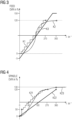
- the characteristic curve K21 shows the "classic" case of a stepped characteristic curve with "jumpy” changes in the feed OVR in 16 steps, distributed over a rotation angle range from 0° to 270°.
- the characteristic curves K22 and K23 are examples of characteristic curves defined by a user.
- K22 establishes a linear relationship between the angle of rotation in a setting range from 0° to 360° and generates associated "SPINDLE-OVR" values in the range from 0% to 120%.
- K23 establishes an at least essentially (from the user's perspective) "smooth", i.e. non-jumpy or non-step-like relationship for angles of rotation starting at 0° and extending beyond 360° and an associated "SPINDLE-OVR" value in the range from 0% to 150%.
- the flattened curve in the range of low or high setting values enables finer adjustment in these ranges.
- Figure 5 shows examples of setting the "FEED-OVR" (feed override).
- Characteristic curve K31 shows a step-like progression of the characteristic curve in a rotation angle range from 0° to 270° and with FEED-OVR values in a range between 0% and 200%.
- Characteristic curve K32 shows a linear smooth curve for a rotation angle range from 0° to 360° with FEED-OVR values in a range between 0% and 200%.
- Characteristic curve K33 shows a smooth, "curved" curve for a rotation angle range from 0° to 360° with FEED-OVR values in a range between 0% and 200%.
- Figure 6 shows an embodiment in which the effective angle of rotation range extends to more than one revolution (360°).
- a first rotation angle range from 0° to 270° there is a linearly increasing relationship to an OVR value in the range from 0% to 120% (see characteristic curve K41).
- a second rotation angle range from 270° to 540° there is a linearly decreasing relationship to an OVR value in the range from 120% to 0% (see characteristic curve K42).
- This alternation between a rising and a falling characteristic curve for value ranges of 270° continues endlessly to the left and right. This results in a linearly falling characteristic curve K43 in the range from -270° to 0°.
- Different gradients or rotation angle ranges could also be specified for the characteristic curves K42 or K43 than for the characteristic curve 41.
- the invention provides for a sensitive variation of the feed or spindle speed, in particular by the fact that the angle of rotation range of the rotary actuator used exceeds 360° (one revolution).
- the problem with this variant is that the operator does not want to turn the OVR 10 times completely in an adjustment range of 10 revolutions, for example, in order to get from a feed rate of 0% to a feed rate of 100%. Not least for this reason, the invention provides for the definition of operating sequences with the help of which certain operating functions, e.g. jumps to certain values, can be triggered.
- a first process step S1 the effect of the feed override, i.e. the change of the OVR value depending on the angle of rotation, is determined by means of an HMI user interface of a CNC control connected to a machine tool.
- a FEED-OVR rotary actuator FEED-OVR
- FEED-OVR FEED-OVR rotary actuator
- a second method step S2 the effect of the spindle override, i.e. the change in the OVR value depending on the angle of rotation of a SPINDLE-OVR rotary actuator (SPINDLE-OVR), is set using the HMI user interface based on a characteristic curve that can be specified by the operator and/or based on at least one operating sequence that can be specified by the operator.
- SPINDLE-OVR SPINDLE-OVR rotary actuator
- a parts program for machining a workpiece using the machine tool is called and started on the CNC control.
- a fourth process step S4 the feed override is set by manual actuation of the FEED-OVR by the user according to the characteristic curve or operating sequence specified in process step S1 and depending on the function currently being performed by the machine tool.
- a spindle override is set by manual actuation of the SPINDLE-OVR by the user according to the characteristic curve or operating sequence specified in process step S2 and depending on the function currently being performed by the machine tool.
- a function of the machine tool in particular a machining of the workpiece by the machine tool, is carried out depending on the set feed override and the set spindle override.
Landscapes
- Engineering & Computer Science (AREA)
- Mechanical Engineering (AREA)
- Human Computer Interaction (AREA)
- Manufacturing & Machinery (AREA)
- Physics & Mathematics (AREA)
- General Physics & Mathematics (AREA)
- Automation & Control Theory (AREA)
- Numerical Control (AREA)
Description
Die Erfindung betrifft eine Bedieneinrichtung für eine CNC-Steuerung zur Steuerung einer Werkzeugmaschine, wobei die Werkzeugmaschine mehrere Maschinenachsen umfasst, mittels der ein in eine Werkzeugaufnahme einer Werkzeugspindel eingesetztes Werkzeug relativ zu einem Werkstück verstellbar und/oder um eine Werkzeugspindelachse rotierbar ist.The invention relates to an operating device for a CNC control for controlling a machine tool, wherein the machine tool comprises several machine axes by means of which a tool inserted into a tool holder of a tool spindle can be adjusted relative to a workpiece and/or rotated about a tool spindle axis.
Ferner betrifft die Erfindung ein Verfahren zum Betrieb einer mittels einer CNC-Steuerung, die eine derartige Bedieneinrichtung umfasst, gesteuerten Werkzeugmaschine.Furthermore, the invention relates to a method for operating a machine tool controlled by means of a CNC control comprising such an operating device.
Werkzeugmaschinen werden heutzutage mit Hilfe einer Steuereinrichtung, wie z.B. einer CNC-Steuerung, gesteuert. Dabei "steuert" die Steuereinrichtung anhand eines Teileprogramms die Bewegungen von Maschinenelementen und damit die Bewegungen eines Werkzeuges, welches beispielsweise über eine Werkzeughaltevorrichtung in die Maschine eingebracht wird, relativ zu einem Werkstück, welches ebenfalls in die Maschine eingebracht wird. Dabei ist dem Fachmann klar, dass es sich bei dem Begriff "steuern" um den üblichen Sprachgebrauch und nicht um "steuern" im Sinne der Regelungstechnik handelt. "Steuern" meint hier vor allem die Vorgabe von Lagesollwerten für die Lageregelung von Achsen, wohinter sich Regelungsvorgänge im Sinne der Regelungstechnik verbergen.Nowadays, machine tools are controlled using a control device, such as a CNC control. The control device uses a parts program to "control" the movements of machine elements and thus the movements of a tool, which is, for example, introduced into the machine via a tool holder, relative to a workpiece, which is also introduced into the machine. It is clear to the expert that the term "control" is in common usage and not "control" in the sense of control engineering. "Control" here primarily means the specification of position setpoints for the position control of axes, behind which control processes in the sense of control engineering are hidden.
Das Teileprogramm setzt sich dabei zumindest überwiegend aus Steuerbefehlen zusammen, die von der Steuereinrichtung eingelesen und interpretiert werden. Entsprechend den Steuerbefehlen steuert die Steuereinrichtung die Bewegungen der Maschinenelemente der Werkzeugmaschine und damit die Bewegung des Werkzeugs relativ zu dem Werkstück.The part program consists at least predominantly of control commands that are read in and interpreted by the control device. In accordance with the control commands, the control device controls the movements of the machine elements of the machine tool and thus the movement of the tool relative to the workpiece.
Das Teileprogramm kann man prinzipiell manuell an einem Editor direkt an der Maschine oder an einem externen Rechner erzeugen.In principle, the part program can be created manually using an editor directly on the machine or on an external computer.
Zur Erstellung eines Teileprogramms werden in der Regel von einem CAM-System (Computer Aided Manufacturing) vorzugsweise in einem standardisierten Datenformat Bewegungsinformationen über durchzuführende Bewegungen des Werkzeugs erzeugt und von einem nachgeschalteten Postprozessor eingelesen. Der Postprozessor erzeugt anhand der vom CAM-System erzeugten Bewegungsinformationen, den Kinematik- und Maschinendaten der Werkzeugmaschine sowie dem Befehlssatz der CNC-Steuerung und dem Befehlssatz der PLC-Steuerung, ein für die jeweilige konkrete Werkzeugmaschine auf denen der Bearbeitungsvorgang stattfinden soll angepasstes Teileprogramm in Form von auf die konkrete Steuereinrichtung der Werkzeugmaschine angepassten Steuerbefehlen. Solchermaßen werden vom Postprozessor die vom CAM-System vorzugsweise in einem standardisierten Datenformat erzeugten Bewegungsinformationen in Steuerbefehle, die von der Steuereinrichtung eingelesen werden können und auf die jeweilige Steuereinrichtung angepasst sind, umgesetzt.To create a parts program, movement information about the movements of the tool to be carried out is usually generated by a CAM system (Computer Aided Manufacturing), preferably in a standardized data format, and read in by a downstream postprocessor. Using the movement information generated by the CAM system, the kinematics and machine data of the machine tool, the command set of the CNC control and the command set of the PLC control, the postprocessor generates a parts program adapted to the specific machine tool on which the machining process is to take place, in the form of control commands adapted to the specific control device of the machine tool. In this way, the postprocessor converts the movement information generated by the CAM system, preferably in a standardized data format, into control commands that can be read in by the control device and are adapted to the specific control device.
Der Postprozessor berücksichtigt dabei neben dem konkret verfügbaren CNC-Befehlssatz die konkreten maschinenspezifischen kinematischen Gegebenheiten der Werkzeugmaschine, wie z.B. Kinematik, geometrische Größenverhältnisse, maximale Verfahrbereiche der Antriebsachsen und Maximalgeschwindigkeiten der Maschinenelemente. Diese Daten liegen in Form von Maschinendaten vor. Weiterhin werden vom Postprozessor bei der Erzeugung der Steuerbefehle maschinenspezifische PLC-Funktionalitäten (Programmable Logic Control), wie z.B. Schmierung, Werkzeugwechsel, Türverriegelung etc. berücksichtigt, wobei die konkret verfügbaren PLC-Funktionalitäten in Form von PLC-Befehlssätzen dem Postprozessor zur Verfügung stehen.In addition to the specific CNC command set available, the postprocessor takes into account the specific machine-specific kinematic conditions of the machine tool, such as kinematics, geometric proportions, maximum travel ranges of the drive axes and maximum speeds of the machine elements. This data is available in the form of machine data. Furthermore, when generating the control commands, the postprocessor takes into account machine-specific PLC (Programmable Logic Control) functionalities, such as lubrication, tool change, door locking, etc., whereby the specific PLC functionalities available are available to the postprocessor in the form of PLC command sets.
Die Bedienung von Werkzeugmaschinen erfolgt über Bedieneinrichtungen wie einem HMI (Human Machine Interface) der CNC-Steuerung, einer mit der CNC-Steuerung verbindbaren Maschinensteuertafel (MCP bzw. Machine Control Panel) oder mittels Handbediengeräten. Bedieneinrichtungen für Werkzeugmaschinen weisen mindestens einen, oft jedoch mehrere, Override- (OVR-) Stellelemente (nachfolgend auch kurz "Override" genannt) zur Beeinflussung der Stellgrößen Vorschubgeschwindigkeit (kurz: Vorschub) der Vorschubachsen oder Spindeldrehzahl der Hauptspindel auf.Machine tools are operated via operating devices such as an HMI (Human Machine Interface) of the CNC control, a machine control panel that can be connected to the CNC control (MCP or Machine Control Panel) or by means of handheld control devices. Control devices for machine tools have at least one, but often several, override (OVR) control elements (hereinafter also referred to as "override") to influence the control variables feed rate (in short: feed) of the feed axes or spindle speed of the main spindle.
Für den Vorschub kann dabei zusätzlich zwischen einem Arbeitsvorschub, bei dem sich das Werkzeug in Eingriff mit dem Werkstück befindet, und einem Eilgang, bei dem sich das Werkzeug nicht in Eingriff befindet, unterschieden werden.For the feed, a distinction can also be made between a working feed, in which the tool is in engagement with the workpiece, and a rapid traverse, in which the tool is not in engagement.
Bekannte Bedieneinrichtungen für CNC-Steuerungen weisen einen einzigen Vorschub-Override auf, mit dem sowohl der Arbeitsvorschub (die Vorschubgeschwindigkeit für den Anwendungsfall, in dem sich das Werkzeug in Eingriff mit dem Werkstück befindet) als auch der Eilgang (die Vorschub- bzw. Eilganggeschwindigkeit für den Anwendungsfall, in dem sich das Werkzeug nicht in Eingriff mit dem Werkstück befindet) getrennt voneinander einstellbar ist, je nachdem, welcher Anwendungsfall bei einer Betätigung des Vorschub-Overrides gerade vorliegt. Es sind aber auch Bedieneinrichtungen bekannt, die separate Vorschub-Overrides für den Arbeitsvorschub und den Eilgang verwenden.Known operating devices for CNC controls have a single feed override with which both the working feed (the feed rate for the application in which the tool is in engagement with the workpiece) and the rapid traverse (the feed or rapid traverse rate for the application in which the tool is not in engagement with the workpiece) can be set separately, depending on which application is currently present when the feed override is activated. However, operating devices are also known that use separate feed overrides for the working feed and the rapid traverse.
In der Regel wird mittels des Stellelements die Stellgröße nicht absolut eingestellt (z.B. die Spindeldrehzahl direkt in U/min bzw. rpm), sondern prozentual bezüglich einem programmierten Wert verändert, z.B. in einem Wertebereich von 0% bis 120% des programmierten Wertes.As a rule, the control variable is not set absolutely using the control element (e.g. the spindle speed directly in rpm), but is changed as a percentage of a programmed value, e.g. in a value range from 0% to 120% of the programmed value.
In der Regel sind Override-Steller heute als Drehsteller mit festen Anschlägen ausgebildet, die sich mittels eines Drehknopfes in einem bestimmten Winkelbereich, z.B. zwischen 0° und 270°, durch manuelle Betätigung eines Drehknopfes einstellen lassen. Es sind jedoch auch Override-Steller in Form von endlos drehbaren Drehstellern (Inkrementalgeber) bekannt. Unter Drehstellern werden im Zusammenhang mit der Erfindung nicht nur "reine" Drehsteller verstanden, die ausschließlich die manuelle Betätigung eines Drehknopfes erlauben, sondern auch solche Bedienelemente, die neben dem Drehknopf noch wenigstens einen Tastschalter (auch als Dreh-Drück-Steller bezeichnet) oder die Funktion eines Steuerhebels (Joysticks) etc. mit umfassen.As a rule, override actuators are designed as rotary actuators with fixed stops that can be set in a specific angle range, e.g. between 0° and 270°, by manually operating a rotary knob. However, override actuators in the form of endlessly rotating rotary actuators (incremental encoders) are also known. In the context of the invention, rotary actuators are understood to mean not only "pure" rotary actuators that only allow the manual operation of a rotary knob, but also those operating elements that, in addition to the rotary knob, also include at least one push button switch (also referred to as a rotary push button) or the function of a control lever (joystick), etc.
Häufig ändert sich der Wert der Stellgröße nicht linear mit der Override-Einstellung (also dem Drehwinkel des Drehknopfes), sondern in diskreten Stufen. So können z.B. im Falle des Spindeloverrides (auch als SPINDLE-OVR bezeichnet) 16 unterschiedlichen Winkelbereichen eines Drehstellers je einer Spindelgeschwindigkeit zugeordnet werden. Dies geschieht z.B. für Einstellungen zwischen 50% und 120% gleichmäßig aufgeteilt in 5% Schritten.The value of the control variable often does not change linearly with the override setting (i.e. the angle of rotation of the rotary knob), but in discrete steps. For example, in the case of spindle override (also known as SPINDLE-OVR), 16 different angle ranges of a rotary actuator can each be assigned to a spindle speed. This is done, for example, for settings between 50% and 120%, evenly divided into 5% steps.
Es wird angemerkt, dass unter dem Begriff "Drehwinkel" sowohl der absolute Winkel verstanden werden kann, den der Drehsteller aktuell einnimmt (z.B. 0° oder 180°), aber auch der Winkelbereich, der bei einer bestimmten Bedienhandlung überstrichen wird (z.B. 20° bei einer Veränderung von 180° auf 200°). Die jeweilige Bedeutung ergibt sich aus dem Kontext.It should be noted that the term "angle of rotation" can be understood as both the absolute angle that the rotary actuator currently assumes (e.g. 0° or 180°), but also the angle range that is covered by a certain operating action (e.g. 20° when changing from 180° to 200°). The respective meaning arises from the context.
Im Falle des Vorschuboverrides (auch als FEED-OVR bezeichnet) wird z.B. der Winkelbereich des Drehstellers von 0° bis 270° in 23 "Schalterstellungen", d.h. Winkelbereiche von jeweils ca. 12° (angelehnt an eine nichtlineare stufenförmige Kennlinie), der prozentualen Vorschubbeeinflussung wie folgt zugeordnet:
Winkelbereich 1 = 0%Winkelbereich 2 = 1%Winkelbereich 3 = 2%Winkelbereich 4 = 4%Winkelbereich 5 = 6%Winkelbereich 6 = 8%Winkelbereich 7 = 10%- Danach (
Winkelbereiche 8 bis 23) in 10% Schritten bis 120%
-
Angle range 1 = 0% -
Angle range 2 = 1% -
Angle range 3 = 2% -
Angle range 4 = 4% -
Angle range 5 = 6% -
Angle range 6 = 8% -
Angle range 7 = 10% - Then (angle ranges 8 to 23) in 10% steps up to 120%
Die nichtlineare Verteilung im Falle des Vorschuboverrides erlaubt dem Bediener eine feinere Abstufung im niedrigen Geschwindigkeitsbereich und ist der endlichen Anzahl an Drehschalterstellungen geschuldet, die bei einer linearen Verteilung der prozentualen Veränderungen zu "großen Sprüngen" im niedrigen Geschwindigkeitsbereich führen würde.The non-linear distribution in the case of the feed override allows the operator a finer gradation in the low speed range and is due to the finite number of rotary switch positions, which would lead to "large jumps" in the low speed range with a linear distribution of the percentage changes.
Insbesondere mit digitalen Inkrementalgebern lassen sich jedoch auch wesentlich feinere Abstufungen und damit für den Benutzer als "stufenlos" erscheinende Kennlinien realisieren. Streng genommen wird bei Werkzeugmaschinen unter der Vorschubgeschwindigkeit die Geschwindigkeit verstanden, mit der sich das Werkzeug relativ zu dem Werkstück zur Bearbeitung des Werkstücks "durch das Werkstück" bewegt, das Werkzeug sich also "in Eingriff" befindet. Mittels des Vorschuboverrides werden in der Regel jedoch analog auch Bewegungen der Maschinenachsen beeinflusst, bei denen sich das Werkzeug nicht in Eingriff befindet, z.B. sogenannte Eilgang-Bewegungen. Im Rahmen dieser Patentanmeldungen sind bei den Begriffen Vorschuboverride bzw. Vorschubgeschwindigkeit ausdrücklich auch solche Bewegungen mit umfasst, bei denen sich das Werkzeug nicht in Eingriff befindet, wie z.B. Eilgang-Bewegungen. Dokumente
Nachteilig bei heutigen Drehstellern zur Beeinflussung der Vorschubgeschwindigkeit oder der Spindeldrehzahl von Werkzeugmaschinen ist deren fehlende Flexibilität hinsichtlich der Anpassung an die Belange des individuellen Benutzers. Eine Aufgabe der vorliegenden Erfindung ist es daher, bei Drehstellern zur Beeinflussung der Vorschubgeschwindigkeit oder der Spindeldrehzahl von Werkzeugmaschinen die Flexibilität hinsichtlich der Anpassung an die Belange des individuellen Benutzers zu verbessern.A disadvantage of today's rotary actuators for influencing the feed rate or spindle speed of machine tools is their lack of flexibility with regard to adaptation to the needs of the individual user. One object of the present invention is therefore to improve the flexibility with regard to adaptation to the needs of the individual user in rotary actuators for influencing the feed rate or spindle speed of machine tools.
Diese Aufgabe wird gelöst durch eine Bedieneinrichtung für eine CNC-Steuerung zur Steuerung einer Werkzeugmaschine mit den in Patentanspruch 1 angegebenen Merkmalen, d.h. eine Bedieneinrichtung für eine CNC-Steuerung zur Steuerung einer Werkzeugmaschine, wobei die Werkzeugmaschine mehrere Maschinenachsen umfasst, mittels der ein in eine Werkzeugaufnahme einer Werkzeugspindel eingesetztes Werkzeug relativ zu einem Werkstück verstellbar und/oder um eine Werkzeugspindelachse rotierbar ist, wobei die Bedieneinrichtung wenigstens einen manuell von einem Bediener der Bedieneinrichtung bedienbaren, endlos drehbaren Drehsteller aufweist, durch den eine Vorschubgeschwindigkeit, mit der sich das Werkzeug relativ zu dem Werkstück bewegt, und/oder eine Spindeldrehzahl manuell durch Drehen an einem Drehknopf des Drehstellers durch den Bediener einstellbar ist, wobei die Bedieneinrichtung eine grafische Bedienerschnittstelle umfasst, mittels der die Wirkung einer mittels des Drehstellers durchgeführten Bedienhandlung auf die Vorschubgeschwindigkeit und/oder die Spindeldrehzahl einstellbar ist.This object is achieved by an operating device for a CNC control for controlling a machine tool with the features specified in
Ferner wird die Aufgabe gelöst durch ein Verfahren mit den in Patentanspruch 14 angegebenen Verfahrensschritten, das heißt ein Verfahren zum Betrieb einer mittels einer CNC-Steuerung, die eine Bedieneinrichtung umfasst, gesteuerten Werkzeugmaschine, wobei die Werkzeugmaschine mehrere Maschinenachsen umfasst, mittels der ein in eine Werkzeugaufnahme einer Werkzeugspindel eingesetztes Werkzeug relativ zu einem Werkstück verstellt wird und/oder um eine Werkzeugspindelachse rotiert, wobei die Bedieneinrichtung wenigstens einen manuell von einem Bediener der Bedieneinrichtung bedienbaren, endlos drehbaren Drehsteller aufweist, durch den eine Vorschubgeschwindigkeit, mit der sich das Werkzeug relativ zu dem Werkstück bewegt, und/oder eine Spindeldrehzahl manuell durch Drehen an einem Drehknopf des Drehstellers durch den Bediener eingestellt wird, wobei die Bedieneinrichtung eine grafische Bedienerschnittstelle umfasst, mittels der die Wirkung (Bedienfunktion) einer mittels des Drehstellers durchgeführten Bedienhandlung (Drehen des Drehknopfes um einen bestimmten Winkel, ggf. innerhalb einer bestimmten Zeit) auf die Vorschubgeschwindigkeit und/oder die Spindeldrehzahl eingestellt wird, wobei ein auf der CNC-Steuerung bereitgestelltes Programm gestartet wird, welches die Bewegung des Werkzeugs relativ zu dem Werkstück vorgibt, wobei eine mittels des Drehstellers durchgeführte Bedienhandlung die Vorschubgeschwindigkeit und/oder die Spindeldrehzahl gemäß der Einstellung ändert.Furthermore, the object is achieved by a method with the method steps specified in claim 14, that is to say a method for operating a machine tool controlled by means of a CNC control which comprises an operating device, wherein the machine tool comprises a plurality of machine axes by means of which a tool inserted into a tool holder of a tool spindle is adjusted relative to a workpiece and/or rotates about a tool spindle axis, wherein the operating device has at least one endlessly rotatable rotary actuator which can be operated manually by an operator of the operating device and by means of which a feed rate at which the tool moves relative to the workpiece and/or a spindle speed is set manually by the operator by turning a rotary knob of the rotary actuator, wherein the operating device comprises a graphical user interface by means of which the effect (operating function) of an operating action carried out by means of the rotary actuator (turning the rotary knob by a certain angle, (if necessary within a certain time) is set to the feed rate and/or the spindle speed, whereby a program provided on the CNC control is started which specifies the movement of the tool relative to the workpiece, whereby an operating action carried out by means of the rotary actuator changes the feed rate and/or the spindle speed according to the setting.
Die Erfindung bietet den Vorteil, dass der Bediener die Wirkung einer mittels des Drehstellers durchgeführten Bedienhandlung auf die Vorschubgeschwindigkeit und/oder die Spindeldrehzahl individuell nach seinen Bedürfnissen und Vorlieben einstellen kann. Insbesondere hat sich gezeigt, dass für verschiedene mit der Werkzeugmaschine durchgeführte Werkstück-Bearbeitungen unterschiedliche Wirkungen einer bestimmten Bedienhandlung optimal sind. Beispielsweise kann bei einer bestimmten Bearbeitung der Wertebereich zwischen 0% und 20% der mittels des OVR eingestellten Geschwindigkeit oder Drehzahl entscheidend sein, wohingegen dieser Wertebereich bei einer anderen Bearbeitung lediglich eine untergeordnete Rolle spielt. Im ersten Fall kann so dem genannten Wertebereich ein verhältnismäßig großer Winkelbereich des Drehstellers zugeordnet werden, so dass in diesem Bereich eine gute "Feineinstellung" gewährleistet werden kann. Insgesamt wird durch die Erfindung mehr Flexibilität im Umgang mit den Override-Stellern erreicht.The invention offers the advantage that the operator can adjust the effect of an operating action carried out using the rotary actuator on the feed rate and/or the spindle speed individually according to his needs and preferences. In particular, it has been shown that different effects of a specific operating action are optimal for different workpiece machining operations carried out with the machine tool. For example, for a specific machining operation, the value range between 0% and 20% of the speed or rpm set using the OVR can be decisive, whereas for another machining operation this value range only plays a subordinate role. In the first case, a relatively large angle range of the rotary actuator can be assigned to the value range mentioned, so that good "fine adjustment" can be guaranteed in this range. Overall, the invention achieves more flexibility in handling the override actuators.
Eine Ausführungsform der Erfindung sieht vor, dass durch Betätigung des Drehstellers ein Drehwinkel einstellbar ist und zum Einstellen der Wirkung der Bedienhandlung ein Zusammenhang zwischen dem Drehwinkel und einem prozentualen Einstellwert (nachfolgend auch als "OVR-Wert" bezeichnet) vorgebbar ist, wobei der prozentuale Einstellwert ein Verhältnis zwischen einer programmierten Vorschubgeschwindigkeit und/oder einer programmierten Spindeldrehzahl und einer tatsächlichen Vorschubgeschwindigkeit und/oder einer tatsächlichen Spindeldrehzahl bestimmt.One embodiment of the invention provides that an angle of rotation can be set by operating the rotary actuator and that a relationship between the angle of rotation and a percentage setting value (hereinafter also referred to as "OVR value") can be specified in order to set the effect of the operating action, wherein the percentage setting value determines a ratio between a programmed feed rate and/or a programmed spindle speed and an actual feed rate and/or an actual spindle speed.
Analog sieht eine Ausführungsform eines erfindungsgemäßen Verfahrens vor, dass durch Betätigung des Drehstellers ein Drehwinkel des Drehknopfes eingestellt wird, wobei zum Einstellen der Wirkung der Bedienhandlung ein Zusammenhang zwischen dem Drehwinkel und einem prozentualen Einstellwert vorgegeben wird, wobei mittels des prozentualen Einstellwertes ein Verhältnis zwischen einer programmierten Vorschubgeschwindigkeit und/oder einer programmierten Spindeldrehzahl und einer tatsächlichen Vorschubgeschwindigkeit und/oder einer tatsächlichen Spindeldrehzahl bestimmt wird.Analogously, an embodiment of a method according to the invention provides that a rotation angle of the rotary knob is set by actuating the rotary actuator, wherein a relationship between the rotation angle and a percentage setting value is specified to set the effect of the operating action, wherein a relationship between a programmed feed rate and/or a programmed spindle speed and an actual feed rate and/or an actual spindle speed is determined by means of the percentage setting value.
Beträgt beispielsweise der programmierte Wert der Spindeldrehzahl 1000 U/min und der prozentuale Einstellwert des Drehstellers beträgt 120%, so ergibt sich eine tatsächliche Spindeldrehzahl von 1000 U/min x 120/100 = 1200 U/min.For example, if the programmed value of the spindle speed is 1000 rpm and the percentage setting value of the rotary actuator is 120%, the actual spindle speed is 1000 rpm x 120/100 = 1200 rpm.
Die Erfindung erlaubt es, eine altbekannte, "klassische" Wirkungsweise eines zuvor verwendeten Drehstellers nachzubilden. So kann der Drehsteller so "programmiert" werden, dass er in einem Winkelbereich zwischen 0° und 270° 16 bzw. 23 Stufen implementiert und für Drehwinkel < 0° der kleinste prozentuale Einstellwert (0 %) und für Drehwinkel > 270° der größte prozentuale Einstellwert (120 %) beibehalten wird.The invention makes it possible to recreate a well-known, "classic" mode of operation of a previously used rotary actuator. The rotary actuator can be "programmed" in such a way that it implements 16 or 23 steps in an angle range between 0° and 270° and that the smallest percentage setting value (0%) is retained for angles of rotation < 0° and the largest percentage setting value (120%) is retained for angles of rotation > 270°.
So kann bei Bedarf (für bestimmte Anwendungen) das Verhalten eines vorbekannten Drehstellers nachgebildet werden, welches dem Bediener vertraut ist.If required (for certain applications), the behavior of a previously known rotary actuator that is familiar to the operator can be simulated.
Darüber hinaus erlaubt es die Erfindung, einen nahezu beliebigen Zusammenhang zwischen Drehwinkel und prozentualem Einstellwert festzulegen (zu "programmieren"). Insbesondere kann so eine zumindest näherungsweise "glatte" (stetige) Kennlinie festgelegt werden.In addition, the invention allows an almost arbitrary relationship between the angle of rotation and the percentage setting value to be defined ("programmed"). In particular, an at least approximately "smooth" (continuous) characteristic curve can be defined in this way.
Eine Ausführungsform der Erfindung sieht vor, dass durch wenigstens eine vorbestimmte Bedienhandlung eine vorbestimmte Bedienfunktion ausführbar ist und ein Zusammenhang zwischen der Bedienfunktion und dem prozentualen Einstellwert vorgebbar ist.An embodiment of the invention provides that a predetermined operating function can be carried out by at least one predetermined operating action and a connection between the operating function and the percentage setting value can be specified.
Analog sieht eine Ausführungsform eines erfindungsgemäßen Verfahrens vor, dass durch wenigstens eine vorbestimmte Bedienhandlung, insbesondere eine Bediensequenz, eine vorbestimmte Bedienfunktion ausgeführt wird, wobei ein Zusammenhang zwischen der Bedienfunktion und dem prozentualen Einstellwert vorgegeben wird.Analogously, an embodiment of a method according to the invention provides that a predetermined operating function is carried out by at least one predetermined operating action, in particular an operating sequence, wherein a relationship between the operating function and the percentage setting value is specified.
Eine Bedienhandlung kann dabei aus einer einzelnen Handlung bestehen, z.B. einmaliges kurzes schnelles Drehen des Drehknopfes des Drehstellers im Uhrzeigersinn. Eine Bedienhandlung kann jedoch auch mehrere, insbesondere in kurzem zeitlichen Abstand nacheinander durchgeführte Handlungen, eine sog. Bediensequenz, umfassen. Eine Bediensequenz kann ferner neben der - insbesondere mehrmaligen - Betätigung des Drehknopfes auch eine Betätigung wenigstens eines weiteren Bedienelements, z.B. das Drücken eines Tasters, umfassen.An operating action can consist of a single action, e.g. a single, quick, short turn of the rotary knob of the rotary control clockwise. However, an operating action can also comprise several actions, particularly those carried out one after the other in a short time interval, a so-called operating sequence. In addition to the actuation of the rotary knob - particularly multiple times - an operating sequence can also comprise the actuation of at least one other operating element, e.g. pressing a button.
Eine Ausführungsform der Erfindung sieht daher vor, dass eine Bediensequenz ausführbar ist, wobei ein Zusammenhang zwischen der Bediensequenz und dem OVR-Wert bzw. der Vorschubgeschwindigkeit bzw. der Spindeldrehzahl vorgebbar ist.An embodiment of the invention therefore provides that an operating sequence can be carried out, wherein a relationship between the operating sequence and the OVR value or the feed rate or the spindle speed can be specified.
Unter einer Bediensequenz wird dabei eine bestimmte, vordefinierte markante Handlung verstanden, die insbesondere durch mehrmalige Betätigung des Drehknopfes des Drehstellers innerhalb eines bestimmten Zeitraums ausgelöst wird.An operating sequence is understood to be a specific, predefined, distinctive action that is triggered in particular by repeatedly pressing the rotary knob of the rotary control within a certain period of time.
Beispiele für Bedienhandlungen bzw. Bediensequenzen sind:
- Einmaliges schnelles, kurzes ("ruckartiges") Drehen des Drehstellers im Uhrzeigersinn;
- Einmaliges schnelles, kurzes ("ruckartiges") Drehen des Drehstellers entgegen dem Uhrzeigersinn;
- Einmaliges schnelles, kurzes ("ruckartiges") Drehen des Drehstellers im Uhrzeigersinn und unmittelbar daran anschließendes einmaliges schnelles, kurzes ("ruckartiges") Drehen des Drehstellers entgegen dem Uhrzeigersinn.
- One quick, short ("jerky") turn of the rotary control clockwise;
- One quick, short ("jerky") turn of the rotary control anti-clockwise;
- One quick, short ("jerky") turn of the rotary control clockwise and immediately thereafter one quick, short ("jerky") turn of the rotary control anti-clockwise.
Die Definition und Verwendung von Bedienhandlungen bzw. Bediensequenzen hat den Vorteil, dass damit eine Unterbrechung des starren Zusammenhangs zwischen Stellwinkel des Drehstellers und dem damit eingestellten OVR-Wert möglich ist. Z.B. lassen sich durch kurzes schnelles Drehen in eine bestimmte Richtung Sprünge des OVR-Wertes auslösen. Der Drehsteller muss somit nicht um den entsprechenden Winkelbereich gedreht werden, um den "Zielwert" zu erreichen.The definition and use of operating actions or operating sequences has the advantage that it makes it possible to interrupt the rigid connection between the setting angle of the rotary actuator and the OVR value set with it. For example, jumps in the OVR value can be triggered by a short, quick turn in a certain direction. The rotary actuator therefore does not have to be turned by the corresponding angle range in order to reach the "target value".
Eine Ausführungsform der Erfindung sieht vor, dass in einem Auswahl-Menü eine Anzahl an Kennlinien vorgegeben ist, von denen eine durch den Bediener auswählbar ist, wobei die ausgewählte Kennlinie den Zusammenhang zwischen dem Stellwinkel des Drehstellers und dem prozentualen Einstellwert bestimmt.One embodiment of the invention provides that a number of characteristic curves are specified in a selection menu, one of which can be selected by the operator, wherein the selected characteristic curve determines the relationship between the setting angle of the rotary actuator and the percentage setting value.
Analog sieht eine Ausführungsform eines erfindungsgemäßen Verfahrens vor, dass in einem Auswahl-Menü eine Anzahl an Kennlinien vorgegeben wird, von denen eine durch den Bediener ausgewählt wird, wobei die ausgewählte Kennlinie den Zusammenhang zwischen dem Drehwinkel und dem prozentualen Einstellwert bestimmt.Analogously, an embodiment of a method according to the invention provides that a number of characteristic curves are specified in a selection menu, one of which is selected by the operator, wherein the selected characteristic curve determines the relationship between the angle of rotation and the percentage setting value.
Für viele Anwendungen kann jeweils eine bestimmte Kennlinie besonders günstig sein, z.B. eine Kennlinie, die eine "Feineinstellung" im unteren Winkelbereich des Drehstellers oder eine Kennlinie, die eine "Feineinstellung" im oberen Winkelbereich des Drehstellers erlaubt. So kann dem Benutzer auf einfache und schnelle Weise eine gute Anpassung an seinen speziellen Bedarf ermöglicht werden, ohne dass er sich dafür selbst eine geeignete Kennlinie definieren müsste.For many applications, a specific characteristic curve can be particularly advantageous, e.g. a characteristic curve that allows a "fine adjustment" in the lower angle range of the rotary actuator or a characteristic curve that allows a "fine adjustment" in the upper angle range of the rotary actuator. This allows the user to easily and quickly adapt the system to their specific needs without having to define a suitable characteristic curve themselves.
Eine Ausführungsform der Erfindung sieht vor, dass die Kennlinie - insbesondere mittels grafischer Hilfsmittel - individuell konfigurierbar ist. Eine individuelle Konfiguration erlaubt die größtmögliche Optimierung für die spezielle Anwendung des jeweiligen Benutzers. Eine Einstellung mittels grafischer Hilfsmittel ist zudem sehr bedienerfreundlich.One embodiment of the invention provides that the characteristic curve - in particular by means of graphical aids - can be individually is configurable. Individual configuration allows the greatest possible optimization for the specific application of the respective user. Setting up using graphical tools is also very user-friendly.
Analog sieht eine Ausführungsform eines erfindungsgemäßen Verfahrens vor, dass eine Kennlinie vorgegeben wird, die den Zusammenhang zwischen dem Drehwinkel und dem prozentualen Einstellwert bestimmt. Dabei wird die Kennlinie gemäß einer bevorzugten Ausführungsform individuell konfiguriert, insbesondere mittels grafischer Hilfsmittel.Analogously, an embodiment of a method according to the invention provides that a characteristic curve is specified which determines the relationship between the angle of rotation and the percentage setting value. In this case, the characteristic curve is individually configured according to a preferred embodiment, in particular by means of graphical aids.
Die grafischen Hilfsmittel können z.B. ein Display und ein Zeigergerät als Eingabemittel umfassen. So kann die Kennlinie z.B. an einem bestimmten Punkt mit einem Mauszeiger angewählt und in diesem Bereich auf dem Display gezogen werden, wobei vorteilhaft bei dieser Aktion ein "glatter" (geschlossener) Verlauf der Kennlinie erhalten bleibt. Ähnliche Funktionen sind von Zeichenprogrammen hinlänglich bekannt.The graphical aids can include a display and a pointing device as input devices. For example, the characteristic curve can be selected at a certain point with a mouse pointer and dragged in this area on the display, whereby a "smooth" (closed) course of the characteristic curve is advantageously maintained during this action. Similar functions are well known from drawing programs.
Eine Ausführungsform der Erfindung sieht vor, dass die Kennlinie wenigstens abschnittweise einen glatten und/oder wenigstens abschnittweise einen stufenförmigen Verlauf aufweist. Die Möglichkeit des stufenförmigen Verlaufs ermöglicht die Einstellung von Kennlinien, die der bisherigen Gewohnheit des Benutzers entsprechen. Ein glatter (zumindest weitgehend "stufenloser") Verlauf vermeidet Sprünge und ermöglicht daher eine feinere Einstellung.One embodiment of the invention provides that the characteristic curve has a smooth and/or at least partially stepped course. The possibility of a stepped course enables the setting of characteristic curves that correspond to the user's previous habits. A smooth (at least largely "stepless") course avoids jumps and therefore enables finer adjustment.
Neben der Einstellung der Kennlinie durch grafische Hilfsmittel sind auch andere Möglichkeiten gegeben. Beispielsweise könnte der Verlauf der Kennlinie auch durch einen mathematischen Term bestimmt sein, bei dem man den Verlauf durch Vorgabe von Parametern ändern kann, um nur eine von vielen weiteren Möglichkeiten zu nennen.In addition to setting the characteristic curve using graphical tools, there are also other options. For example, the curve could be determined by a mathematical term, where the curve can be changed by specifying parameters, to name just one of many other possibilities.
Eine Ausführungsform der Erfindung sieht vor, dass die Kennlinie bei Verwendung eines Drehstellers einen Drehwinkelbereich größer 360° und/oder negative Drehwinkel abdeckt, wobei sich insbesondere die Rotations-Richtung der Spindel oder die Bewegungsrichtung des Werkzeugs bei negativen Drehwinkeln gegenüber positiven Drehwinkeln umkehrt (bei Vorschub bedeutet dies "Rückwärtsfahren").An embodiment of the invention provides that the characteristic curve when using a rotary actuator covers a rotation angle range greater than 360° and/or negative angles of rotation, whereby in particular the direction of rotation of the spindle or the direction of movement of the tool is reversed at negative angles of rotation compared to positive angles of rotation (in the case of feed this means "moving backwards").
Analog sieht eine Ausführungsform eines erfindungsgemäßen Verfahrens vor, dass die Kennlinie einen Drehwinkelbereich größer 360° und/oder negative Drehwinkel abdeckt, wobei negativen Drehwinkeln negative prozentuale Einstellwerte zugeordnet werden und wobei sich die Rotations-Richtung der Spindel oder die Bewegungsrichtung des Werkzeugs bei negativen Drehwinkeln gegenüber positiven Drehwinkeln umkehrt.Analogously, an embodiment of a method according to the invention provides that the characteristic curve covers a rotation angle range greater than 360° and/or negative rotation angles, wherein negative rotation angles are assigned negative percentage setting values and wherein the direction of rotation of the spindle or the direction of movement of the tool is reversed at negative rotation angles compared to positive rotation angles.
Ein Drehwinkelbereich größer 360°, der die Zuordnung unterschiedlicher OVR-Werte auf einen Winkelbereich des Drehstellers von mehr als 360°, insbesondere auf ein Vielfaches von 360° erstreckt, erlaubt eine noch genauere Justierung des OVR-Wertes, die bei bestimmten Anwendungen besonders vorteilhaft ist. Beispielsweise kann der Wertebereich des OVR-Wertes von 0% bis 120% auf zwei vollständige Umdrehungen des Drehstellers, also auf einen Winkelbereich von 720° abgebildet werden.A rotation angle range greater than 360°, which extends the assignment of different OVR values to an angle range of the rotary actuator of more than 360°, in particular to a multiple of 360°, allows an even more precise adjustment of the OVR value, which is particularly advantageous in certain applications. For example, the value range of the OVR value from 0% to 120% can be mapped to two complete revolutions of the rotary actuator, i.e. to an angle range of 720°.
So kann z.B. bei einem Drehsteller mit 256 Stufen (Inkrementen bzw. kurz "Ink") bei einer Ausweitung des Drehwinkelbereiches auf 10 vollständige Umdrehungen die Auflösung der Geschwindigkeitsänderung um den Faktor 10 gegenüber einem herkömmlichen Override-Steller mit nur einer möglichen Umdrehung geändert werden. Die Auflösung des OVR-Wertes beträgt dann nur ca. 0,05 %/Ink, wie nachfolgende Rechnung zeigt: ![]()
![]()
Beträgt die typische Bearbeitungsgeschwindigkeit der Achse, die per OVR beeinflusst werden kann, beispielsweise 10m/min, so ist eine Auflösung der Geschwindigkeit Δ v möglich von: ![]()
![]()
Damit ist eine sehr feine Einstellung der aktuellen Vorschubgeschwindigkeit oder der Spindeldrehzahl möglich, die beispielsweise benötigt wird, um Ratterschwingungen durch den Bediener effizient durch feinfühlige Variation eben des Vorschubs oder der Spindeldrehzahl zu unterdrücken.This enables a very fine adjustment of the current feed rate or spindle speed, which is required, for example, to efficiently suppress chatter vibrations caused by the operator by sensitively varying the feed rate or spindle speed.
Weiterhin kann die Möglichkeit einer schnellen und einfachen Dreh- bzw. Bewegungsrichtungsumkehr bei vielen Anwendungen hilfreich und vorteilhaft sein. So kann z.B. ein Werkzeug einfach und schnell entgegen der Vorschubrichtung von dem Werkstück entfernt werden. Dies ist insbesondere dann der Fall, wenn negativen Drehwinkeln (z.B. -20° bzw. beginnend bei 0°, Linksdrehung um 20°) negative OVR-Werte (z.B. -5%) zugeordnet werden.Furthermore, the possibility of a quick and easy reversal of rotation or direction of movement can be helpful and advantageous in many applications. For example, a tool can be easily and quickly removed from the workpiece against the feed direction. This is particularly the case when negative OVR values (e.g. -5%) are assigned to negative angles of rotation (e.g. -20° or starting at 0°, anti-clockwise rotation by 20°).
Eine Ausführungsform der Erfindung sieht vor, dass unterschiedlichen Winkelbereichen unterschiedliche Bedienfunktionen zuordenbar sind.One embodiment of the invention provides that different operating functions can be assigned to different angular ranges.
Analog sieht eine Ausführungsform eines erfindungsgemäßen Verfahrens vor, dass unterschiedlichen Winkelbereichen unterschiedliche Bedienfunktionen zugeordnet werden.Analogously, an embodiment of a method according to the invention provides that different operating functions are assigned to different angular ranges.
Beispielsweise können zunehmende Drehwinkel des Drehstellers in einem Drehwinkelbereich zwischen 0° und 360° zu einer Zunahme der Vorschubgeschwindigkeit und zunehmende Drehwinkel des Drehstellers in einem Winkelbereich zwischen 360° und 720° zu einer Abnahme der Vorschubgeschwindigkeit führen. So können durch Drehen des Drehstellers in ein und derselben Richtung unterschiedliche Bedienfunktionen (Erhöhung des OVR-Wertes, Reduzierung des OVR-Wertes) ausgeführt werden.For example, increasing the angle of rotation of the rotary actuator in a range of angles between 0° and 360° can lead to an increase in the feed rate, and increasing the angle of rotation of the rotary actuator in a range of angles between 360° and 720° can lead to a decrease in the feed rate. In this way, different operating functions (increasing the OVR value, reducing the OVR value) can be carried out by turning the rotary actuator in one and the same direction.
Prinzipiell können bestimmten Drehwinkeln des Drehstellers beliebige OVR-Werte zugeordnet werden. So können auch Kennlinien mit einem oder mehreren Nulldurchgängen hinsichtlich der OVR-Werte realisiert werden. Prinzipiell können diese Nulldurchgänge auch im Bereich positiver Drehwinkel liegen, so dass auch positiven Drehwinkeln negative OVR-Werte zugeordnet werden können.In principle, any OVR value can be assigned to certain angles of rotation of the rotary actuator. In this way, characteristic curves with one or more zero crossings with regard to the OVR values can also be realized. In principle, these zero crossings can also lie in the range of positive rotation angles, so that negative OVR values can also be assigned to positive rotation angles.
Ebenso ist es möglich, dass bestimmten Drehwinkelbereichen, insbesondere negativen Drehwinkeln, z.B. Drehwinkeln in einem Drehwinkelbereich zwischen 0° und -360°, negative prozentuale Einstellwerte zuordenbar sind. Vorzugsweise kehrt sich dabei die Rotations-Richtung der Spindel oder die Bewegungsrichtung des Werkzeugs in diesen Drehwinkelbereichen bzw. bei diesen Drehwinkeln gegenüber anderen Drehwinkelbereichen bzw. anderen Drehwinkeln um.It is also possible that negative percentage setting values can be assigned to certain angle of rotation ranges, in particular negative angles of rotation, e.g. angles of rotation in a range of angles between 0° and -360°. Preferably, the direction of rotation of the spindle or the direction of movement of the tool in these angle of rotation ranges or at these angles of rotation is reversed compared to other angle of rotation ranges or other angles of rotation.
Eine Ausführungsform eines erfindungsgemäßen Verfahrens sieht vor, bestimmten Drehwinkelbereichen, insbesondere negativen Drehwinkeln, negative prozentuale Einstellwerte zugeordnet werden, wobei sich insbesondere die Rotations-Richtung der Spindel oder die Bewegungsrichtung des Werkzeugs in diesen Drehwinkelbereichen bzw. bei diesen Drehwinkeln gegenüber anderen Drehwinkelbereichen bzw. anderen Drehwinkeln (denen positive prozentuale Einstellwerte zugeordnet sind) umkehrt.One embodiment of a method according to the invention provides for negative percentage setting values to be assigned to certain angle of rotation ranges, in particular negative angles of rotation, wherein in particular the direction of rotation of the spindle or the direction of movement of the tool in these angle of rotation ranges or at these angles of rotation is reversed compared to other angle of rotation ranges or other angles of rotation (to which positive percentage setting values are assigned).
Eine Ausführungsform der Erfindung sieht vor, dass unterschiedlichen Bediensequenzen unterschiedliche Bedienfunktionen zuordenbar sind.One embodiment of the invention provides that different operating functions can be assigned to different operating sequences.
Analog sieht eine Ausführungsform eines erfindungsgemäßen Verfahrens vor, dass unterschiedlichen Bedienhandlungen bzw. Bediensequenzen unterschiedliche Bedienfunktionen zugeordnet werden.Analogously, an embodiment of a method according to the invention provides that different operating functions are assigned to different operating actions or operating sequences.
Wenn der Benutzer selbst festlegen kann, welche Bedienfunktion er für welche Bediensequenz vorsieht, wird ein hohes Maß an Individualisierung bei der Bedienung erreicht.If the user can determine which operating function he wants to use for which operating sequence, a high degree of individualization in operation is achieved.
Insbesondere erlaubt es diese Möglichkeit dem Bediener, individuell besonders einprägsame oder einfach auszuführende Bediensequenzen besonders oft verwendeten Bedienfunktionen zuzuordnen. So kann die Bedienbarkeit für den individuellen Bediener weiter verbessert werden.In particular, this option allows the operator to individually assign particularly memorable or easy-to-execute operating sequences to particularly frequently used operating functions. In this way, usability for the individual operator can be further improved.
Eine Ausführungsform der Erfindung sieht vor, dass Bediensequenzen individuell gestaltbar und/oder lernbar sind.One embodiment of the invention provides that operating sequences can be individually designed and/or learned.
Analog sieht eine Ausführungsform eines erfindungsgemäßen Verfahrens vor, dass Bedienhandlungen bzw. Bediensequenzen individuell gestaltet und/oder gelernt werden.Analogously, an embodiment of a method according to the invention provides that operating actions or operating sequences are individually designed and/or learned.
Diese Funktion erlaubt es dem Bediener, seine eigenen Bediensequenzen zu definieren. So können Bediensequenzen z.B. aufgezeichnet und gelernt werden, was dem individuellen Gestaltungsspielraum bei der Bedienung mittels eines Drehstellers nahezu keine Grenzen setzt.This function allows the operator to define his own operating sequences. For example, operating sequences can be recorded and learned, which means there are almost no limits to the individual design options when operating the device using a rotary control.
Eine Ausführungsform der Erfindung sieht vor, dass die Wirkung der mittels des Drehsteller durchgeführten Bedienhandlung auf die Vorschubgeschwindigkeit und/oder die Spindeldrehzahl abhängig von einer von der Werkzeugmaschine ausführbaren Funktion vorgebbar ist.One embodiment of the invention provides that the effect of the operating action carried out by means of the rotary actuator on the feed rate and/or the spindle speed can be specified depending on a function that can be carried out by the machine tool.
Analog sieht eine Ausführungsform eines erfindungsgemäßen Verfahrens vor, dass für unterschiedliche von der Werkzeugmaschine ausführbare Funktionen unterschiedliche Wirkungen der mittels des Drehsteller durchgeführten Bedienhandlungen auf die Vorschubgeschwindigkeit und/oder die Spindeldrehzahl vorgegeben werden.Analogously, an embodiment of a method according to the invention provides that for different functions that can be carried out by the machine tool, different effects of the operating actions carried out by means of the rotary actuator on the feed rate and/or the spindle speed are specified.
Zu den von (bzw. mittels) der Werkzeugmaschine ausführbaren Funktionen gehören insbesondere die mit der Werkzeugmaschine ausführbaren Bearbeitungsarten. So erlauben insbesondere Universal-Werkzeugmaschinen die Ausführung unterschiedlicher Bearbeitungen, z.B. Drehen, Fräsen und Bohren, mit ein und derselben Maschine.The functions that can be carried out by (or by means of) the machine tool include, in particular, the types of machining that can be carried out with the machine tool. Universal machine tools in particular allow different machining operations, e.g. turning, milling and drilling, to be carried out with one and the same machine.
Weiterhin wird - wie eingangs bereits erwähnt - unterschieden zwischen Bearbeitungs-Funktionen (Bearbeitungsarten), bei denen sich das Werkzeug in Eingriff befindet, und Bewegungs-Funktionen, bei denen Werkzeug und Werkstück voneinander beabstandet sind, z.B. Eilgang-Bewegungen.Furthermore, as already mentioned at the beginning, a distinction is made between processing functions (processing types) in which the tool is engaged, and movement functions in which the tool and workpiece are spaced apart, e.g. rapid traverse movements.
Die Erfindung sieht vor, dass für unterschiedliche Funktionen der Maschine unterschiedliche Wirkungen (Bedienfunktionen) einer bestimmten, mittels des Vorschuboverrides oder des Spineloverrides durchgeführten Bedienhandlung eingestellt werden können.The invention provides that for different functions of the machine, different effects (operating functions) of a specific operating action carried out by means of the feed override or the spin override can be set.
So kann beispielsweise für die Bearbeitungsart "Drehen" eine andere Vorschuboverride-Kennlinie eingestellt und bei dieser Bearbeitungsart automatisch wirksam werden als z.B. bei der Bearbeitungsart "Fräsen". Weiterhin kann auch für die Funktion "Bewegung im Eilgang" eine andere Vorschuboverride-Kennlinie eingestellt und bei dieser Bearbeitungsart automatisch wirksam werden als z.B. bei einer für eine bestimmte Bearbeitungsart eingestellten Kennlinie.For example, a different feed override characteristic can be set for the "turning" machining type and automatically take effect for this machining type than, for example, for the "milling" machining type. Furthermore, a different feed override characteristic can be set for the "rapid traverse" function and automatically take effect for this machining type than, for example, a characteristic set for a specific machining type.
Insbesondere erkennt die CNC-Steuerung, welche Bearbeitungsart mittels der betreffenden Werkzeugmaschine gerade ausgeführt wird, z.B. anhand des aktuell ausgeführten Befehls aus dem Teileprogramm, wie z.B. einem "G0"-Befehl für einen Eilgang oder einem aufgerufenen Fräszyklus, und stellt den für diese Funktion vorgegebenen Zusammenhang zwischen der mittels des betreffenden Drehstellers ausgeführten Bedienhandlung und der damit erzielten Wirkung (Bedienfunktion) her. Selbstverständlich ist eine derartige Zuordnung nicht nur für unterschiedlichen Kennlinien möglich, sondern allgemein für die mit dem jeweiligen Drehsteller ausführbaren Bedienhandlungen bzw. Bediensequenzen und die damit ausgelösten Bedienfunktionen.In particular, the CNC control recognizes which type of machining is currently being carried out using the relevant machine tool, e.g. based on the currently executed command from the part program, such as a "G0" command for rapid traverse or a called milling cycle, and establishes the connection specified for this function between the operating action carried out using the relevant rotary actuator and the effect achieved thereby (operating function). Of course, such an assignment is not only possible for different characteristics, but generally for the operating actions or operating sequences that can be carried out using the respective rotary actuator and the operating functions triggered by them.
Die Möglichkeit der Anpassung der Wirkung der mittels der Drehsteller ausgeführten Bedienhandlungen an unterschiedliche Funktionen der Werkzeugmaschine ermöglicht eine noch bessere Anpassung dieser Bedienelemente an den jeweiligen Bedarfsfall. So kann für eine bestimmte mittels der Werkzeugmaschine durchgeführte Bearbeitung eine im oberen und unteren Vorschubgeschwindigkeitsbereich sehr flache Kennlinie und für andere Funktionen, z.B. Bewegung im Eilgang, z.B. eine lineare Kennlinie vorgegeben werden.The possibility of adapting the effect of the operating actions carried out using the rotary actuators to different functions of the machine tool enables these operating elements to be adapted even better to the respective requirements. For example, for a specific function carried out using the machine tool For the machining process carried out, a very flat characteristic curve can be specified in the upper and lower feed rate range and for other functions, e.g. movement in rapid traverse, a linear characteristic curve can be specified.
Auch kann beispielsweise der Bedienhandlung "kurzes schnelles Rechtsdrehen" des Vorschuboverrides während eines Bearbeitungs-Vorgangs die Bedienfunktion "Sprung um 10%" und für dieselbe Bedienhandlung während einer Eilgangsbewegung die Bedienfunktion "Sprung um 20%" zugeordnet werden.For example, the operating action "short, quick right turn" of the feed override during a machining process can be assigned the operating function "jump by 10%" and the same operating action during a rapid traverse movement can be assigned the operating function "jump by 20%".
Die Erfindung wird nachfolgend anhand von Ausführungsbeispielen exemplarisch näher beschrieben und erläutert. Dabei zeigen:
- FIG 1
- Ein Werkzeugmaschinensystem mit einer erfindungsgemäßen Bedieneinrichtung,
- FIG 2
- eine CNC-Steuerung mit einer erfindungsgemäßen Bedieneinrichtung,
- FIG 3
- verschiedene Kennlinien für einen Feed-Override,
- FIG 4
- verschiedene Kennlinien für einen Spindle-Override,
- FIG 5
- Kennlinien für einen Drehsteller-Winkelbereich > 360°,
- FIG 6
- Kennlinien für einen Drehsteller-Winkelbereich > 360°,
- FIG 7
- die Definition unterschiedlicher Bediensequenzen,
- FIG 8
- die Wirkung unterschiedlicher Bediensequenzen,
- FIG 9
- ein Auswahl-Menü für unterschiedliche Kennlinien und Winkelbereiche,
- FIG 10
- ein Auswahl-Menü für unterschiedliche Bediensequenzen,
- FIG 11
- Verfahrensschritte bei der Durchführung eines erfindungsgemäßen Verfahrens.
- FIG 1
- A machine tool system with an operating device according to the invention,
- FIG 2
- a CNC control with an operating device according to the invention,
- FIG 3
- different characteristics for a feed override,
- FIG 4
- different characteristics for a spindle override,
- FIG 5
- Characteristic curves for a rotary actuator angle range > 360°,
- FIG 6
- Characteristic curves for a rotary actuator angle range > 360°,
- FIG 7
- the definition of different operating sequences,
- FIG 8
- the effect of different operating sequences,
- FIG 9
- a selection menu for different characteristics and angle ranges,
- FIGURE 10
- a selection menu for different operating sequences,
- FIGURE 11
- Process steps in carrying out a process according to the invention.
In
Der Drehmeißel 1 lässt sich mit der im Ausführungsbeispiel gezeigten Maschine 20 mit der Übersichtlichkeit halber in
Darüber hinaus verfügt die Maschine 20 über eine dritte lagegeregelte Rundachse C, die parallel zur Z-Achse verläuft, und bezüglich der der Werkstücktisch 7 relativ zu einem ruhenden Maschinengestell 23 drehbar gelagert ist. Dadurch kann das Werkstück 5 auch in einer Winkellage γ relativ zu dem Werkzeug 1 positioniert werden. Auch hier wurde der Übersichtlichkeit halber auf eine Darstellung des Antriebs verzichtet. Abhängig von der durchzuführenden Bearbeitung ist bei der gezeigten Werkzeugmaschine 20 auch ein drehzahlgeregelter Betrieb bezüglich der Werkzeugspindel bzw. des Motors 22 möglich.In addition, the
Die Werkzeugmaschine 20 gemäß dem Ausführungsbeispiel weist somit sechs Maschinenachsen (die 3 Linearachsen X, Y und Z sowie die 3 Rundachsen A, B und C) auf, d.h. es handelt sich um eine sogenannte 6-achsige Werkzeugmaschine (6-Achs-Maschine) 20.The
Es sei an dieser Stelle angemerkt, dass die Werkzeugmaschine 20 selbstverständlich auch noch mehr, aber auch weniger als sechs Maschinenachsen aufweisen kann.It should be noted at this point that the
Die Werkzeugmaschine 20 ist mit einer numerischen Steuerung (CNC-Steuerung) 30 verbunden, die anhand eines von der CNC-Steuerung ausgeführten Teileprogramms und/oder einer Handbedieneingabe Lagesollwerte x, y, z, α, β und γ zur Steuerung einer zwischen dem Werkzeug 1 und dem Werkstück 5 stattfindenden Relativbewegung ermittelt. Die numerische Steuerung 30 ermittelt die Lagesollwerte anhand des Teileprogramms, in dem die vom Werkzeug 1 in Bezug zum Werkstück 5 durchzuführende Bewegung in Form von Befehlen (und Positionswerten) definiert ist. Alternativ oder zusätzlich kann die Bewegung des Werkzeugs 1 und/oder des Werkstücks 5 auch mittels einer Handbedieneingabe über eine Bedieneinrichtung 31, die eine Anzeigevorrichtung in Form eines Displays 32 umfasst, der numerischen Steuerung 30 von einem Bediener vor Ort an der Werkzeugmaschine 20 vorgegeben werden. Die Bedieneinrichtung 31 weist hierzu insbesondere Eingabefelder, Tasten und Drehsteller (auch als Drehregler bezeichnet) auf. Weiterhin ist die Anzeigevorrichtung als grafische Bedienoberfläche, insbesondere als Touch-Display 32 ausgebildet, mittels der der Bediener - neben der Anzeige-Funktion - auch Eingaben in die CNC-Steuerung vornehmen und so z.B. die Werte bestimmter Parameter ändern kann. Hierfür weist das Display 32 insbesondere die Eingabefelder 33 und 34 auf.The
Das von der CNC-Steuerung ausgeführte Teileprogramm wird üblicherweise von einem externen CAM/CAD-System (nicht dargestellt) und einem eventuell dem CAM/CAD-System nachgeschalteten sogenannten Postprozessor (nicht dargestellt) außerhalb der numerischen Steuerung 30 erzeugt und von dort auf die numerische Steuerung 30 übertragen.The part program executed by the CNC control is usually generated by an external CAM/CAD system (not shown) and a so-called postprocessor (not shown) possibly connected downstream of the CAM/CAD system outside the
Bei der Abarbeitung des Teileprogramms erzeugt die numerische Steuerung 30 in einem bestimmten Takt, dem Interpolationstakt, sowohl Lagesollwerte x, y und z für die Linearachsen als auch α, β und γ (Winkellagen) für die Rundachsen. Durch diese Lagesollwerte wird das Werkzeug 1 mit vorgegebener Orientierung und einer bestimmten Vorschubgeschwindigkeit relativ zu dem Werkstück 5 entlang einer Bewegungsbahn bewegt.When executing the part program, the
Neben der genannten Drehbearbeitung des Werkstücks 5 ließe sich mit der gezeigten 6-Achs-Maschine ebenso beispielsweise eine Fräsbearbeitung des Werkstücks 5 durchführen, bei der das Werkzeug 1 als um die Spindelachse A rotierender Fräser (nicht dargestellt) ausgebildet ist, der in X-, Y- und Z-Richtung lagegeregelt positioniert wird und bei der das Werkstück 5 vorzugsweise ortsfest befestigt ist. Der Antrieb des Fräsers durch den Motor 22 und die Spindel 21 würde dabei drehzahlgeregelt mit einer durch das Teileprogramm vorgegebenen Spindeldrehzahl erfolgen.In addition to the aforementioned turning of the
Weiterhin zeigt
Weiterhin umfasst die Bedieneirichtung der CNC-Steuerung 30 die Drehsteller 35 und 36, wobei mit dem Drehsteller 35 (als Spindeloverride bzw. "SPINDLE-Override" bezeichnet) der prozentuale Einstellwert (OVR-Wert) für die Spindeldrehzahl und mit dem Drehsteller 36 (als Vorschuboverride bzw. "FEED-Override" bezeichnet) der prozentuale Einstellwert für die Vorschubgeschwindigkeit bzw. Eilganggeschwindigkeit einstellbar ist.Furthermore, the operating device of the
In dem Displaybereich 33 des Displays 32 sind die aktuellen, prozentualen Einstellwerte für den SPINDLE-Override (70%) und den FEED-Override (70%) ersichtlich. Diese Einstellungen bedeuten, dass die aktuellen, tatsächlichen Werte für die Spindeldrehzahl und die Vorschubgeschwindigkeit jeweils nur 70% von ihrem programmierten Wert betragen.The current percentage setting values for the SPINDLE override (70%) and the FEED override (70%) are visible in the
In einem Display-Bereich 34 ist weiterhin die Kennlinie angegeben, aus der sich für einen bestimmten eingestellten Drehwinkel des FEED-Override 36 der dazugehörige OVR-Wert ergibt.A
Aus dem flachen Verlauf der Kennlinie im oberen und im unteren Winkelbereich ergibt sich, dass der OVR-Wert in diesen Bereichen besonders fein justiert werden kann.The flat course of the characteristic curve in the upper and lower angle ranges means that the OVR value can be adjusted particularly finely in these areas.
Die
Im Unterschied dazu ist eine "geschwungene", stetig verlaufende Kennlinie K2 ersichtlich, die z.B. 256 oder mehr Stufen eines digitalen Drehgebers nutzt, wodurch für den Benutzer keine Stufen bzw. Sprünge mehr erkennbar sind, weder bei der Bedienung der Werkzeugmaschine noch aus der grafischen Darstellung der Kennlinie, wie z.B. aus
Die Kennlinie K2 ist im Bereich geringer Vorschübe (niedriger OVR-Werte) und im Bereich hoher Vorschübe (hoher OVR-Werte) abgeflacht. Zudem kann diese Kennlinie wahlweise einen wirksamen Drehwinkelbereich von 6/8 Umdrehungen (270°) oder eben auch höhere Winkelbereiche bis 360 Grad oder sogar darüber hinaus aufweisen. Die OVR-Werte liegen für die im Beispiel gewählte Kennlinie K2 zwischen 0% und 120%.The characteristic curve K2 is flattened in the area of low feed rates (low OVR values) and in the area of high feed rates (high OVR values). In addition, this characteristic curve can optionally have an effective angle of rotation range of 6/8 revolutions (270°) or even higher angle ranges up to 360 degrees or even beyond. The OVR values for the characteristic curve K2 selected in the example are between 0% and 120%.
Weiterhin ist beispielhaft in
Dargestellt ist im Beispiel der Kennlinie K3 ferner die Möglichkeit, dass mit dem OVR auch ein negativer Vorschub von z.B. -5% eingestellt werden kann. Die möglichen OVR-Werte liegen somit bei der beispielhaften Kennlinie K3 im Bereich zwischen -5% und 150%.The example of the characteristic curve K3 also shows the possibility of setting a negative feed rate of, for example, -5% with the OVR. The possible OVR values for the example characteristic curve K3 are therefore in the range between -5% and 150%.
Ähnlich verhält es sich bei den beispielhaft in
Aus
Die Kennlinie K21 zeigt den "klassischen" Fall einer gestuften Kennlinie mit "sprunghaften" Änderungen des Vorschub-OVR in 16 Stufen, verteilt über einen Drehwinkelbereich von 0° bis 270°.The characteristic curve K21 shows the "classic" case of a stepped characteristic curve with "jumpy" changes in the feed OVR in 16 steps, distributed over a rotation angle range from 0° to 270°.
Die Kennlinie K22 und K23 sind Beispiele für von einem Benutzer definierte Kennlinien. K22 stellt einen linearen Zusammenhang zwischen dem Drehwinkel in einem Einstellbereich von 0° bis 360° her und erzeugt damit verbundene "SPINDLE-OVR-" Werte im Bereich von 0% und 120%. Im Unterschied dazu stellt K23 einen wenigstens im Wesentlichen (aus Sicht des Benutzers) "glatten", d.h. nicht sprunghaften bzw. nicht stufenförmigen Zusammenhang für Drehwinkel beginnend bei 0° und über 360° hinaus reichend und einem damit einhergehenden "SPINDLE-OVR-" Wert im Bereich von 0% und 150% her. Der abgeflachte Verlauf im Bereich niedriger oder hoher Einstellwerte ermöglicht eine feinere Einstellung in diesen Bereichen.The characteristic curves K22 and K23 are examples of characteristic curves defined by a user. K22 establishes a linear relationship between the angle of rotation in a setting range from 0° to 360° and generates associated "SPINDLE-OVR" values in the range from 0% to 120%. In contrast, K23 establishes an at least essentially (from the user's perspective) "smooth", i.e. non-jumpy or non-step-like relationship for angles of rotation starting at 0° and extending beyond 360° and an associated "SPINDLE-OVR" value in the range from 0% to 150%. The flattened curve in the range of low or high setting values enables finer adjustment in these ranges.
Insgesamt bieten die Möglichkeit der Einstellung individueller Kennlinien folgende Vorteile für den Benutzer:
- Freie Definition des wirksamen Drehwinkel-Bereiches z.B. zwischen 0° und 6/8tel einer Umdrehung (270°) oder einer vollen Umdrehung (360°);
- Freie Definition des wirksamen OVR-Wertebereiches z.B. zwischen -1% und +150%;
- Freie Definition des Zusammenhangs zwischen dem Drehwinkel und dem OVR-Wert und damit der Geschwindigkeits- bzw. Drehzahlbeeinflussung;
- Das Maß der Beeinflussung kann in einem bestimmten Bereich durch eine flache Kennlinie verfeinert werden (z.B. bei 0%);
- Das Maß der Beeinflussung kann in einem bestimmten Bereich durch eine steile Kennlinie vergröbert werden (z.B. nahe 75%) ;
- Es kann auch weiterhin ein "stufiges Verhalten" eingestellt werden, womit das Verhalten altbekannter Drehsteller nachgebildet werden kann;
- Möglichkeit der Einstellung eines Mix aus kontinuierlicher Kennlinie und stufiger Kennlinie;
- Die Anzahl der Inkremente (Stufen), die für die nichtlineare Kennlinie verwendet wird, kann frei gewählt werden;
- Free definition of the effective angle of rotation range, e.g. between 0° and 6/8ths of a revolution (270°) or a full revolution (360°);
- Free definition of the effective OVR value range, e.g. between -1% and +150%;
- Free definition of the relationship between the angle of rotation and the OVR value and thus the influence on speed or rpm;
- The degree of influence can be refined in a certain range by a flat characteristic curve (e.g. at 0%);
- The degree of influence can be coarsened in a certain range by a steep characteristic curve (e.g. close to 75%);
- It is still possible to set a "stepped behavior", which can be used to simulate the behavior of well-known rotary controls;
- Possibility of setting a mix of continuous characteristic curve and stepped characteristic curve;
- The number of increments (steps) used for the nonlinear characteristic curve can be freely selected;
In der Prozessbeeinflussung ergeben sich für den Anwender dadurch z.B. folgende Vorteile:
- Vergrößerung der Empfindlichkeit der Geschwindigkeitsvorgabe im niedrigen Geschwindigkeitsbereich um 0% beim Vorschub-OVR;
- Vergrößerung der Empfindlichkeit der Geschwindigkeitsvorgabe im
hohen Geschwindigkeitsbereich um 100% beim Vorschub-OVR (Feinjustage zur geringfügigen Modifikation der Geschwindigkeit zur Vermeidung von Ratterschwingungen); - Vergrößerung der Empfindlichkeit der Geschwindigkeitsvorgabe im
hohen Geschwindigkeitsbereich um 100% beim Spindel-OVR (Feinjustage zur geringfügigen Modifikation der Geschwindigkeit zur Vermeidung von Ratterschwingungen);
- Increase the sensitivity of the speed setting in the low speed range by 0% for the feed OVR;
- Increased the sensitivity of the speed setting in the high speed range by 100% for the feed OVR (fine adjustment for slight modification of the speed to avoid chatter vibrations);
- Increased the sensitivity of the speed setting in the high speed range by 100% for the spindle OVR (fine adjustment for slight modification of the speed to avoid chatter vibrations);
Kennlinie K32 zeigt einen linearen glatten Verlauf für einen Drehwinkel-Bereich von 0° bis 360° mit FEED-OVR-Werten in einem Bereich zwischen 0% und 200%.Characteristic curve K32 shows a linear smooth curve for a rotation angle range from 0° to 360° with FEED-OVR values in a range between 0% and 200%.
Kennlinie K33 zeigt einen glatten, "geschwungenen" Verlauf für einen Drehwinkel-Bereich von 0° bis 360° mit FEED-OVR-Werten in einem Bereich zwischen 0% und 200%.Characteristic curve K33 shows a smooth, "curved" curve for a rotation angle range from 0° to 360° with FEED-OVR values in a range between 0% and 200%.
Außerhalb des gültigen Drehwinkel-Bereiches (d.h. für Drehwinkel < 0° oder > 360°) wird der zuletzt geltende OVR-Wert beibehalten.Outside the valid angle of rotation range (ie for angles of rotation < 0° or > 360°), the last valid OVR value is retained.
In einem ersten Drehwinkel-Bereich von 0° bis 270° gilt ein linear steigender Zusammenhang zu einem OVR-Wert im Bereich von 0% und 120% (vgl. Kennlinie K41). Darüber hinaus gilt in einem zweiten Drehwinkel-Bereich von 270° bis 540° ein linear fallender Zusammenhang zu einem OVR-Wert im Bereich von 120% und 0% (vgl. Kennlinie K42). Dieser Wechsel zwischen einer steigenden und einer fallenden Kennlinie für Wertebereiche von 270° setzt sich endlos nach links und rechts fort. So ergibt sich eine linear fallende Kennlinie K43 im Bereich von -270° bis 0°. Auch könnten für die Kennlinien K42 oder K43 andere Steigungen bzw. Drehwinkelbereiche vorgegeben werden als für die Kennlinie 41.In a first rotation angle range from 0° to 270°, there is a linearly increasing relationship to an OVR value in the range from 0% to 120% (see characteristic curve K41). In addition, in a second rotation angle range from 270° to 540°, there is a linearly decreasing relationship to an OVR value in the range from 120% to 0% (see characteristic curve K42). This alternation between a rising and a falling characteristic curve for value ranges of 270° continues endlessly to the left and right. This results in a linearly falling characteristic curve K43 in the range from -270° to 0°. Different gradients or rotation angle ranges could also be specified for the characteristic curves K42 or K43 than for the
Insgesamt bieten die beispielhaft in den
- Die letzte Endstellung wird nicht wie heute üblich "gehalten", sondern es werden weiter Inkremente ausgewertet, z.B. endlos Zig-Zag (vgl.
Figur 6 ); - Beim Weiterdrehen des Drehstellers schließt sich an eine erste Bedienfunktion (Wirkung), z.B. lineare Zunahme des OVR-Wertes, eine weitere Bedienfunktion bzw. Wirkung an, z.B. lineare Abnahme des OVR-Wertes:
- ∘ z.B.
bei Überschreiten von 120% findet wieder eine Verringerung des OVR-Wertes statt, - ∘ z.B. bei Unterschreiten der 0% findet wieder eine Vergrößerung des OVR statt, ggf. mit anderer Steigung,
- ∘ Wird der minimale oder maximale OVR-Wert, z.B. 0% oder 120%, "durchlaufen", so kann dieser Wert auch für einen bestimmten Zeitraum automatisch fixiert werden, um dem Bediener den erreichten Endwert kenntlich zu machen, da dieser Wert nur schwer genau getroffen werden kann;
- ∘ z.B.
- Auf Wunsch des Benutzers gibt es keine "Endstellungen" mehr, z.B. bei Wahl einer aus
Figur 4 ersichtlichen, "asymptotischen" Kennlinie K23; - Alternative Kennlinien könnten beim Unterschreiten des 0%-Wertes auch einen negativen OVR-Wert und damit eine negative Vorschubgeschwindigkeit ("Rückwärtsfahren") oder Spindeldrehzahl ("Drehrichtungsumkehr") ausgegeben.
- The last end position is not "held" as is usual today, but further increments are evaluated, e.g. endless zig-zag (cf.
Figure 6 ); - As the rotary knob continues to rotate, a first operating function (effect), e.g. linear increase in the OVR value, is followed by another operating function or effect, e.g. linear decrease in the OVR value:
- ∘ e.g. if 120% is exceeded, the OVR value will decrease again,
- ∘ e.g. if the value falls below 0%, the OVR increases again, possibly with a different gradient,
- ∘ If the minimum or maximum OVR value, e.g. 0% or 120%, is "run through", this value can also be automatically fixed for a certain period of time in order to inform the operator of the final value reached. to make, since this value is difficult to determine precisely;
- At the user's request, there are no longer any "end positions", e.g. when selecting one of
Figure 4 visible, "asymptotic" characteristic curve K23; - Alternative characteristics could also output a negative OVR value when the value falls below 0% and thus a negative feed rate ("reverse") or spindle speed ("reversal of rotation").
In der Prozessbeeinflussung ergeben sich für den Anwender dadurch z.B. folgende Vorteile:
- Die Auflösung für die Geschwindigkeitsbeeinflussung kann über die Anzahl der Umdrehungen des OVR erhöht werden. Dies hat z.B. Vorteile bei kleinen Modifikationen, die der Maschinenbediener macht, um das Rattern bei einer Fräsbearbeitung oder Drehbearbeitung zu unterbinden;
- Neue Möglichkeiten wie "Rückwärtsfahren" durch Betätigung des Override-Stellers.
- The resolution for influencing the speed can be increased by increasing the number of revolutions of the OVR. This has advantages, for example, for small modifications that the machine operator makes to prevent chatter during milling or turning operations;
- New possibilities such as "reversing" by operating the override control.
Um eine sehr feine Einstellung des aktuellen Vorschubs oder der Spindeldrehzahl zu möglich, die beispielsweise benötigt wird, um Ratterschwingungen durch den Bediener effizient zu unterdrücken, sieht die Erfindung eine feinfühlige Variation eben des Vorschubs oder der Spindeldrehzahl vor, insbesondere dadurch, dass der verwendete Drehwinkelbereich des Drehstellers 360° (eine Umdrehung) übersteigt.In order to enable a very fine adjustment of the current feed or spindle speed, which is required, for example, to efficiently suppress chatter vibrations caused by the operator, the invention provides for a sensitive variation of the feed or spindle speed, in particular by the fact that the angle of rotation range of the rotary actuator used exceeds 360° (one revolution).
Problematisch bei dieser Variante ist, dass der Bediener bei einem Verstellbereich von z.B. 10 Umdrehungen den OVR nicht 10x komplett drehen möchte, um von einem Vorschub von 0% auf einen Vorschub von 100% zu kommen. Nicht zuletzt aus diesem Grund sieht die Erfindung die Definition von Bediensequenzen vor, mit deren Hilfe bestimmte Bedienfunktionen, z.B. Sprünge bestimmter Werte, ausgelöst werden können.The problem with this variant is that the operator does not want to turn the
Folgende Voraussetzungen sind bei einem erfindungsgemäßen, endlos drehenden OVR erfüllt, damit Bediensequenzen definiert und verwendet werden können:
- Die Auswertung der Verdrehgeschwindigkeit in [Inkrementen/Zeiteinheit] des OVR;
- Die Erkennung spezifizierter Einzel-Drehmuster, welche innerhalb eines festgelegten ersten Zeitraums stattfinden müssen, um als solche erkannt zu werden;
- Die Erkennung einer Abfolge von mehreren Einzel-Drehmustern, welche innerhalb eines festgelegten zweiten Zeitraums stattfinden müssen, um als solche erkannt zu werden.
- The evaluation of the twisting speed in [increments/time unit] of the OVR;
- The detection of specified individual rotation patterns which must occur within a specified initial period of time to be recognized as such;
- The detection of a sequence of several individual rotation patterns, which must occur within a specified second period of time to be recognized as such.
Beispiele für "Einzelmuster" und deren Auswirkungen sind:
- Durch ein "Schnelldrehen" in positiver Drehrichtung mit Verdrehgeschwindigkeit z.B. >25 Ink / s wird ein vordefinierter "positiver OVR-Sprung" von z.B. 10% erkannt und sofort eingestellt. Da sich der OVR nach der sofortigen Einstellung der 10%-igen Änderung noch immer drehen kann, wird die Auswertung des OVR anschließend für einen definierbaren Zeitraum unterdrückt und der OVR stabil auf der um 10% geänderten Einstellung gehalten,
siehe Figur 7 , Zeitbereich t zwischen 2s und 4s. - Durch ein "Schnelldrehen" in negativer Drehrichtung mit Verdrehgeschwindigkeit z.B. >25 Ink / s wird ein vordefinierter "negativer OVR-Sprung" von -10% erkannt und sofort eingestellt. Da sich der OVR nach der sofortigen Einstellung der -10%-igen Änderung noch immer drehen kann, wird die Auswertung des OVR für einen definierbaren Zeitraum unterdrückt und der OVR stabil auf der um -10% geänderten Einstellung gehalten.
- By "quickly turning" in a positive direction of rotation with a turning speed of e.g. >25 inc / s, a predefined "positive OVR jump" of e.g. 10% is detected and set immediately. Since the OVR can still rotate after the immediate setting of the 10% change, the evaluation of the OVR is then suppressed for a definable period of time and the OVR is kept stable at the setting changed by 10%, see
Figure 7 , time range t between 2s and 4s. - By "quickly turning" in a negative direction with a turning speed of e.g. >25 inc/s, a predefined "negative OVR jump" of -10% is detected and set immediately. Since the OVR can still rotate after the immediate setting of the -10% change, the evaluation of the OVR is suppressed for a definable period of time and the OVR is kept stable at the setting changed by -10%.
Beispiele für eine "Abfolge von Einzelmustern" und deren Auswirkungen sind:
- Durch ein zweimalig kurz hintereinander ausgeführtes "Schnelldrehen" in positiver Drehrichtung mit Verdrehgeschwindigkeit von jeweils z.B. >25 Ink / s und einer dazwischenliegenden Pause von <1s wird ein gewünschter, vordefinierter "OVR-Wert = 100%" erkannt und sofort eingestellt. Da sich der OVR-Wert nach der sofortigen Änderung auf 100% noch immer drehen kann, wird die Auswertung des OVR anschließend für einen definierbaren Zeitraum unterdrückt und der OVR auf der neuen Einstellung (100%) gehalten,
siehe Figur 7 . - Durch ein zweimalig kurz hintereinander ausgeführtes "Schnelldrehen" in negativer Drehrichtung mit Verdrehgeschwindigkeit von jeweils z.B. >25 Ink / s und einer dazwischenliegenden Pause von <1s wird ein gewünschter
OVR von 0% erkannt und sofort eingestellt. Da sich der OVR nach der sofortigen Änderung auf 0% noch immer drehen kann, wird die Auswertung des OVR für einen definierbaren Zeitraum unterdrückt und der OVR auf der neuen Einstellung gehalten (nicht dargestellt). - Durch die vordefinierte Abfolge (Bediensequenz) "Schnelldrehen" in positiver Richtung und "Schnelldrehen" in negativer Richtung (innerhalb eines bestimmten Zeitraums) kann beispielsweise die damit verbundene, vordefinierte Bedienfunktion "Umschaltung der Feinheit der OVR-Kennlinie
um den Faktor 10" erreicht werden,siehe Figur 8 . Die Kennlinie K61 repräsentiert den Zusammenhang vor der Umschaltung ("normale" Kennlinie), die Kennlinie K62 den Zustand nach der Umschaltung, wobeidie Kennlinie K62 1/10 der Steigung der Kennlinie K61 aufweist. - Auch ist das automatische Umschalten auf eine feinere OVR-Kennlinie möglich, immer dann wenn eine neue OVR statisch erreicht wird. Ein Zurückschalten auf die Original-Kennlinie kann dann beispielsweise - ebenfalls automatisch - durch einen Schnelldrehvorgang erreicht werden. Die feine Kennlinie kommt dann zum Tragen, wenn der Maschinenbediener den OVR-Steller zur Feinjustage langsam dreht, also z.B. < 10 Inkremente/s.
- Durch weitere ähnliche Abfolgen wie beispielsweise "Schnelldrehen" in positiver Richtung und anschließendes "Schnelldrehen" in negativer Richtung unmittelbar gefolgt von nochmaligem "Schnelldrehen" in positiver Richtung können weitere beliebige OVR-Einstellung und Charakteristika eingestellt werden.
- Ebenso sind - neben den beispielhaft gezeigten - beliebige weitere Bedienfunktionen möglich, die bestimmten Bedienhandlungen (Bediensequenzen) zugeordnet werden können.
- By performing "quick rotation" twice in quick succession in a positive direction of rotation with a rotation speed of e.g. >25 inc/s each time and a pause of <1s in between, a desired, predefined "OVR value = 100%" is recognized and set immediately. Since the OVR value can still rotate after the immediate change to 100%, the evaluation of the OVR is then suppressed for a definable period of time and the OVR is kept at the new setting (100%), see
Figure 7 . - By performing "quick rotation" twice in quick succession in a negative direction of rotation with a rotation speed of, for example, >25 inc/s each time and a pause of <1s in between, a desired OVR of 0% is detected and set immediately. Since the OVR can still rotate after the immediate change to 0%, the evaluation of the OVR is suppressed for a definable period of time and the OVR is kept at the new setting (not shown).
- The predefined sequence (operating sequence) "Fast rotation" in the positive direction and "Fast rotation" in the negative direction (within a certain period of time) can be used to achieve, for example, the associated predefined operating function "Switching the fineness of the OVR characteristic curve by a factor of 10", see
Figure 8 The characteristic curve K61 represents the relationship before the switchover ("normal" characteristic curve), the characteristic curve K62 the state after the switchover, whereby the characteristic curve K62 has 1/10 of the slope of the characteristic curve K61. - It is also possible to automatically switch to a finer OVR characteristic curve whenever a new OVR is statically reached. Switching back to the original characteristic curve can then be achieved, for example - also automatically - by a quick turning process. The fine characteristic curve comes into play when the machine operator turns the OVR actuator slowly for fine adjustment, e.g. < 10 increments/s.
- By further similar sequences such as "quick turning" in the positive direction and then "quick turning" in the negative direction immediately followed by another "quick turning" in the positive direction, any other OVR setting and characteristics can be set.
- In addition to the examples shown, any other operating functions are also possible, which can be assigned to specific operating actions (operating sequences).
Insgesamt bieten die Möglichkeit der Definition von Bediensequenzen und deren Zuordnung zu bestimmten Bedienfunktionen folgende Vorteile für den Benutzer:
- Werden nicht nur die überfahrenen Inkremente ausgewertet, sondern auch die Drehgeschwindigkeit (überfahrenen Inkremente je Zeiteinheit) sowie die Abfolge von Mustern, so bietet der OVR-Steller Möglichkeiten für erweiterte Bedienhandlungen;
- Beispielsweise kann der OVR über 10 Umdrehungen ausgewertet werden und der Bediener kann trotzdem auf einfachste Art und Weise schnell
eine 0%- oder eine 100%- Stellung (oder beliebige andere vordefinierte OVR-Werte) erreichen sowie ggf. die zwischenliegenden Positionen in 10%- (oder beliebigen anderen, vordefinierten) Schritten; - Ein einfaches Umschalten der Empfindlichkeit der OVR-Kennlinie von "Grob" auf "Fein" und zurück, oder generell ein schnelles Umschalten zwischen verschiedenen Kennlinien, ist möglich.
- If not only the increments traveled over are evaluated, but also the rotational speed (increments traveled over per unit of time) and the sequence of patterns, the OVR actuator offers possibilities for extended operating actions;
- For example, the OVR can be evaluated over 10 revolutions and the operator can still easily reach a 0% or 100% position (or any other predefined OVR value) and, if necessary, the intermediate positions in 10% (or any other predefined) steps;
- It is possible to easily switch the sensitivity of the OVR characteristic curve from "coarse" to "fine" and back, or generally to quickly switch between different characteristics.
In der Prozessbeeinflussung ergeben sich für den Anwender dadurch z.B. folgende Vorteile:
- Vergrößerung der Empfindlichkeit der Geschwindigkeitsvorgabe im gesamten Geschwindigkeitsbereich zwischen 0% und einer Obergrenze, z.B. 120%, beim Vorschuboverride;
- Vergrößerung der Empfindlichkeit der Geschwindigkeitsvorgabe im gesamten Geschwindigkeitsbereich beim Spindeloverride (Feinjustage zur geringfügigen Modifikation der Geschwindigkeit zur Vermeidung von Ratterschwingungen).
- Increasing the sensitivity of the speed setting in the entire speed range between 0% and an upper limit, e.g. 120%, during feed override;
- Increasing the sensitivity of the speed setting across the entire speed range during spindle override (fine adjustment for slight modification of the speed to avoid chattering vibrations).
Gemäß der Erfindung besteht die Möglichkeit, dass ein Bediener das Verhalten seines endlos drehenden OVR-Stellers individuell, insbesondere über das HMI der Steuerung, konfigurieren kann. Dazu gehören beispielsweise:
- Auswahl einer von mehreren mittels der Werkzeugmaschine durchführbaren Funktionen, für die die nachfolgend aufgezeigten Einstellungen gelten sollen. In den Ausführungsbeispielen
gemäß den Figuren 9 und 10 besteht hierzu jeweils die Möglichkeit, diese Auswahl durch Markieren der Check-Boxen "G0" (für einen Eilang-Befehl) oder "Gn" (für alle Nicht-Eilang-Befehle) zu treffen oder in die Felder "G □" jeweils eine Zahl einzutragen, die den speziellen G-Befehl spezifiziert, für den die nachfolgenden Einstellungen gelten sollen; - Auswahl einer von mehreren vorgegebenen Kennlinien des OVR-Stellers über eine Liste im Bedienbereich des HMI 40 (vgl.
Figur 9 ). Dabei kann der Bediener imAusführungsbeispiel gemäß Figur 9 zwischen den Kennlinien-Formen "linear", "geschwungen" oder "stufig" durch Markieren der jeweiligen Check-Box wählen. Nach der entsprechenden Auswahl gelangt der Bediener ggf. in ein Untermenü (nicht dargestellt), in dem Details der gewählten Kennlinienform (Steigung, Parameter eines mathematischen Terms, Stufenanzahl und -höhe) eingestellt werden können; - Neudefinition einer individuellen Kennlinie des OVR-Stellers im Bedienbereich der HMI;
- Auswahl des individuellen auszuwertenden Drehwinkelbereiches des OVR über eine vorgegebene Liste im Bedienbereich des HMI (vgl.
Figur 9 ). Dabei kann der Bediener im Ausführungsbeispiel durch Anwählen der entsprechenden Check-Box zwischen den wirksamen Drehwinkelbereichen "0°bis 270°", "0°bis 360°" und "0° bis 720°" wählen; - Eingabe eines individuellen auszuwertenden Drehwinkelbereiches des OVR über den Bedienbereich des HMI;
- Zuordnung vordefinierter Bedienhandlungen (Bediensequenzen) zu vordefinierten Bedienfunktionen (Wirkungen) der jeweiligen Bedienhandlung. Dabei kann der Bediener im
Ausführungsbeispiel gemäß Figur 10 auf einer ersichtlichen Bildschirmmaske 41 des HMI durch Belegen der entsprechenden Check-Box auswählen, ob die Bediensequenz "Schnelldrehen links" einen Sprung des OVR-Wertes um 10%, 20% oder - 10% auslöst, ob die Bediensequenz "2x Schnelldrehen rechts" einen Sprung des OVR-Wertesauf den Wert 50% oder 100% auslöst oder ob die Bediensequenz "Rechts - Links - Rechts" ein "Umschalten auf Kennlinie 1" oder ein "Umschalten auf Kennlinie 2" auslöst; - Freie Zuordnung von Drucktasten und Bedienfunktion über das HMI (mit Anpassung der Funktionsbezeichnung im Touch-Druckschalter) .
- Selection of one of several functions that can be carried out by the machine tool, for which the settings shown below should apply. In the embodiments according to the
Figures 9 and 10 it is possible to make this selection by marking the check boxes "G0" (for an Eilang command) or "Gn" (for all non-Eilang commands) or by entering a number in the "G □" fields that specifies the special G command for which the following settings should apply; - Selection of one of several predefined characteristics of the OVR actuator via a list in the operating area of the HMI 40 (see
Figure 9 ). In the embodiment shown in the figure, the operator canFigure 9 choose between the characteristic curve forms "linear", "curved" or "stepped" by marking the corresponding check box. After making the corresponding selection, the operator may be taken to a submenu (not shown) in which details of the selected characteristic curve form (slope, parameters of a mathematical term, number and height of steps) can be set; - Redefinition of an individual characteristic curve of the OVR actuator in the operating area of the HMI;
- Selection of the individual angle of rotation range of the OVR to be evaluated via a predefined list in the operating area of the HMI (see
Figure 9 ). In the example shown, the operator can choose between the effective angle of rotation ranges "0° to 270°", "0° to 360°" and "0° to 720°" by selecting the corresponding check box; - Entering an individual angle of rotation range of the OVR to be evaluated via the operating area of the HMI;
- Allocation of predefined operating actions (operating sequences) to predefined operating functions (effects) of the respective operating action. In the embodiment, the operator can
Figure 10 on avisible screen mask 41 of the HMI, select by filling the corresponding check box whether the operating sequence "quick turn left" triggers a jump in the OVR value by 10%, 20% or -10%, whether the operating sequence "2x quick turn right" triggers a jump in the OVR value to thevalue 50% or 100% or whether the operating sequence "right - left - right" triggers a "switch tocharacteristic curve 1" or a "switch tocharacteristic curve 2"; - Free assignment of push buttons and operating functions via the HMI (with adaptation of the function name in the touch push button).
In
In einem ersten Verfahrensschritt S1 wird mittels einer HMI-Bedienoberfläche einer mit einer Werkzeugmaschine verbundenen CNC-Steuerung die Wirkung des Vorschuboverrides, das heißt die Veränderung des OVR-Wertes in Abhängigkeit des Drehwinkels eines FEED-OVR-Drehstellers (FEED-OVR), anhand einer durch den Bediener vorgebbaren Kennlinie und/oder anhand von wenigstens einer durch den Bediener vorgebbaren Bediensequenz eingestellt.In
In a first process step S1, the effect of the feed override, i.e. the change of the OVR value depending on the angle of rotation, is determined by means of an HMI user interface of a CNC control connected to a machine tool. a FEED-OVR rotary actuator (FEED-OVR), based on a characteristic curve that can be specified by the operator and/or based on at least one operating sequence that can be specified by the operator.
Dabei ist es insbesondere möglich, unterschiedlichen Funktionen der Werkzeugmaschine (Drehen, Fräsen, Bohren, Bewegung im Eilgang etc.) verschiedene Kennlinien bzw. verschiedene Bediensequenzen zuzuordnen.In particular, it is possible to assign different characteristics or different operating sequences to different functions of the machine tool (turning, milling, drilling, rapid traverse, etc.).
In einem zweiten Verfahrensschritt S2 wird mittels der HMI-Bedienoberfläche die Wirkung des Spindeloverrides, das heißt die Veränderung des OVR-Wertes in Abhängigkeit des Drehwinkels eines SPINDLE-OVR-Drehstellers (SPINDLE-OVR), anhand einer durch den Bediener vorgebbaren Kennlinie und/oder anhand von wenigstens einer durch den Bediener vorgebbaren Bediensequenz eingestellt.In a second method step S2, the effect of the spindle override, i.e. the change in the OVR value depending on the angle of rotation of a SPINDLE-OVR rotary actuator (SPINDLE-OVR), is set using the HMI user interface based on a characteristic curve that can be specified by the operator and/or based on at least one operating sequence that can be specified by the operator.
Auch hier ist es insbesondere möglich, unterschiedlichen Funktionen der Werkzeugmaschine (Drehen, Fräsen, Bohren, Bewegung im Eilgang etc.) verschiedene Kennlinien bzw. verschiedene Bediensequenzen zuzuordnen.Here, too, it is possible to assign different characteristics or different operating sequences to different functions of the machine tool (turning, milling, drilling, rapid traverse, etc.).
In einem dritten Verfahrensschritt S3 wird auf der CNC-Steuerung ein Teileprogramm zur Bearbeitung eines Werkstücks mittels der Werkzeugmaschine aufgerufen und gestartet.In a third process step S3, a parts program for machining a workpiece using the machine tool is called and started on the CNC control.
In einem vierten Verfahrensschritt S4 wird der Vorschuboverride durch manuelle Betätigung des FEED-OVR durch den Benutzer gemäß der in Verfahrensschritt S1 vorgegebenen Kennlinie oder Bediensequenz und in Abhängigkeit der aktuell von der Werkzeugmaschine ausgeführten Funktion eingestellt.In a fourth process step S4, the feed override is set by manual actuation of the FEED-OVR by the user according to the characteristic curve or operating sequence specified in process step S1 and depending on the function currently being performed by the machine tool.
In einem fünften Verfahrensschritt S5 wird der Spindeloverride durch manuelle Betätigung des SPINDLE-OVR durch den Benutzer gemäß der in Verfahrensschritt S2 vorgegebenen Kennlinie oder Bediensequenz und in Abhängigkeit der aktuell von der Werkzeugmaschine ausgeführten Funktion eingestellt.In a fifth process step S5, the spindle override is set by manual actuation of the SPINDLE-OVR by the user according to the characteristic curve or operating sequence specified in process step S2 and depending on the function currently being performed by the machine tool.
In einem Verfahrensschritt S6 wird eine Funktion der Werkzeugmaschine, insbesondere eine Bearbeitung des Werkstücks durch die Werkzeugmaschine, in Abhängigkeit des eingestellten Vorschuboverrides und des eingestellten Spindeloverrides durchgeführt.In a method step S6, a function of the machine tool, in particular a machining of the workpiece by the machine tool, is carried out depending on the set feed override and the set spindle override.
Vorsorglich wird darauf hingewiesen, dass die beispielhaft genannten Verfahrensschritte S1 bis S6 bei einem erfindungsgemäßen Verfahren nicht alle und auch nicht in der genannten Reihenfolge ausgeführt werden müssen.As a precaution, it is pointed out that the exemplary method steps S1 to S6 do not all have to be carried out in a method according to the invention and also not in the order mentioned.
Claims (15)
- Operating facility (31) for a CNC control system (30) for controlling a machine tool (20),wherein the machine tool (20) comprises a plurality of machine axes (X, Y, Z, A, B, C) by means of which a tool (1) inserted into a tool receptacle (2) of a tool spindle (21) is able to be displaced relative to a workpiece (5) and/or to be rotated about a tool spindle axis (A),wherein the operating facility (31) has at least one endlessly rotatable rotary controller (35, 36) which is able to be manually operated by an operator of the operating facility (31), by way of which rotary controller a feed rate with which the tool (1) is moved relative to the workpiece (5) and/or a spindle rotary speed is able to be manually set by the operator by rotating a rotary knob of the rotary controller (35, 36),characterised in that the operating facility (31) comprises a graphical user interface (32) by means of which the effect of an operating action carried out by means of the rotary controller (35, 36) on the feed rate and/or the spindle rotary speed is able to be adjusted.
- Operating facility (31) according to claim 1, wherein by actuating the rotary controller (35, 36), a rotary angle of the rotary knob is able to be set and wherein for setting the effect of the operating action, a relationship between a rotation angle and a percentage set value is able to be specified, wherein the percentage set value determines a relationship between a programmed feed rate and/or a programmed spindle rotary speed and an actual feed rate and/or an actual spindle rotary speed.
- Operating facility (31) according to claim 1 or 2, wherein by way of at least one predetermined operating action, in particular an operating sequence, a predetermined operating function is able to be executed and wherein a relationship between the operating function and the percentage set value is able to be specified.
- Operating facility (31) according to claim 2 or 3, wherein a characteristic line (K1, K2, K3; K21, K22, K23; K31, K32, K33; K41, K42, K43, K44; K51, K52; K61, K62) is able to be specified which determines the relationship between the rotation angle and the percentage set value.
- Operating facility (31) according to claim 4, wherein in a selection menu (40), a number of characteristic lines is specified from which one is able to be selected by the operator, wherein the selected characteristic line determines the relationship between the rotation angle and the percentage set value.
- Operating facility (31) according to claim 5, wherein the characteristic line is able to be configured individually, in particular using graphical aids.
- Operating facility (31) according to one of claims 4 to 6, wherein the characteristic line (K2) has an at least partially smooth and/or an at least partially stepped shape (K1).
- Operating facility (31) according to one of claims 4 to 7, wherein the characteristic line (K23) covers a rotation angle range of greater than 360° and/or a negative rotation angle (K43) .
- Operating facility (31) according to one of claims 4 to 8, wherein different rotation angle ranges are able to be assigned different operating functions.
- Operating facility (31) according to one of claims 2 to 9, wherein negative percentage set values are able to be assigned to particular rotation angle ranges, in particular negative rotation angles, and wherein the rotation direction of the spindle or the movement direction of the tool in these rotation angle ranges or at these rotation angles becomes reversed in relation to other rotation angle ranges or other rotation angles.
- Operating facility (31) according to one of claims 3 to 10, wherein different operating actions or operating sequences are able to be assigned different operating functions.
- Operating facility (31) according to claim 11, wherein operating actions or operating sequences are able to be individually configured and/or learned.
- Operating facility (31) according to one of the preceding claims, wherein the effect of the operating action carried out by means of the rotary controller on the feed rate and/or the spindle rotary speed is able to be specified dependent upon a function that is able to be carried out by the machine tool (20) .
- Method for operating a machine tool (20) controlled by means of a CNC control system (30) which comprises an operating facility (31),wherein the machine tool (20) comprises a plurality of machine axes (X, Y, Z, A, B, C) by means of which a tool (1) inserted into a tool receptacle (2) of a tool spindle (21) is displaced relative to a workpiece (5) and/or is rotated about a tool spindle axis (A),wherein the operating facility (31) has at least one endlessly rotatable rotary controller (35, 36) which is able to be manually operated by an operator of the operating facility (31), by way of which a feed rate with which the tool (1) is moved relative to the workpiece (5) and/or a spindle rotary speed is manually set by the operator by rotating a rotary knob of the rotary controller (35, 36),characterised in that the operating facility (31) comprises a graphical user interface (32) by means of which the effect of an operating action carried out by means of the rotary controller on the feed rate and/or the spindle rotary speed is set,wherein a program which is provided on the CNC control system and which specifies the movement of the tool relative to the workpiece is started,wherein an operating action carried out by means of the rotary controller changes the feed rate and/or the spindle rotary speed according to the setting.
- CNC control system with an operating facility (31) according to one of claims 1 to 13.
Priority Applications (3)
| Application Number | Priority Date | Filing Date | Title |
|---|---|---|---|
| EP21192416.2A EP4137898B1 (en) | 2021-08-20 | 2021-08-20 | Control device for a cnc control system |
| US17/890,594 US20230057688A1 (en) | 2021-08-20 | 2022-08-18 | Operating facility for a cnc control system |
| CN202210998255.6A CN115708023A (en) | 2021-08-20 | 2022-08-19 | Operating device for computer numerical control system |
Applications Claiming Priority (1)
| Application Number | Priority Date | Filing Date | Title |
|---|---|---|---|
| EP21192416.2A EP4137898B1 (en) | 2021-08-20 | 2021-08-20 | Control device for a cnc control system |
Publications (3)
| Publication Number | Publication Date |
|---|---|
| EP4137898A1 EP4137898A1 (en) | 2023-02-22 |
| EP4137898C0 EP4137898C0 (en) | 2024-04-17 |
| EP4137898B1 true EP4137898B1 (en) | 2024-04-17 |
Family
ID=77431233
Family Applications (1)
| Application Number | Title | Priority Date | Filing Date |
|---|---|---|---|
| EP21192416.2A Active EP4137898B1 (en) | 2021-08-20 | 2021-08-20 | Control device for a cnc control system |
Country Status (3)
| Country | Link |
|---|---|
| US (1) | US20230057688A1 (en) |
| EP (1) | EP4137898B1 (en) |
| CN (1) | CN115708023A (en) |
Family Cites Families (3)
| Publication number | Priority date | Publication date | Assignee | Title |
|---|---|---|---|---|
| EP3130973A1 (en) * | 2015-08-14 | 2017-02-15 | Siemens Aktiengesellschaft | Machine control panel for operating a machine tool |
| AT519166A2 (en) * | 2016-09-14 | 2018-04-15 | Keba Ag | Control device for operating a machine tool, in particular a milling or lathe, and corresponding machine tool |
| JP7232243B2 (en) * | 2017-08-01 | 2023-03-02 | ケバ インダストリアル オートメーション ゲゼルシャフト ミット ベシュレンクテル ハフツング | Controller for industrial machinery |
-
2021
- 2021-08-20 EP EP21192416.2A patent/EP4137898B1/en active Active
-
2022
- 2022-08-18 US US17/890,594 patent/US20230057688A1/en active Pending
- 2022-08-19 CN CN202210998255.6A patent/CN115708023A/en active Pending
Also Published As
| Publication number | Publication date |
|---|---|
| CN115708023A (en) | 2023-02-21 |
| EP4137898C0 (en) | 2024-04-17 |
| EP4137898A1 (en) | 2023-02-22 |
| US20230057688A1 (en) | 2023-02-23 |
Similar Documents
| Publication | Publication Date | Title |
|---|---|---|
| DE4291618C2 (en) | Computer numerically controlled machine with a manual control unit for controlling a programmed travel path | |
| DE60126855T2 (en) | Teaching controller for robots | |
| DE60115053T2 (en) | Method and system for user support for editing parameter setting | |
| DE102013004692B4 (en) | 3D input device with an additional rotary controller | |
| WO2018049447A1 (en) | Control device and control method for industrial machines having controlled movement drives | |
| DE102008059116B4 (en) | Microtome with concentric controls for controlling a motor unit | |
| WO2006092406A1 (en) | Input device, input method, corresponding computer program, and corresponding computer-readable storage medium | |
| WO2005096113A2 (en) | Control device for displacing at least one machine axis of a machine tool or production machine | |
| DE102017004926A1 (en) | Numerical control | |
| EP3513261B1 (en) | Control device for operating a machine tool, in particular a milling machine or lathe, and corresponding machine tool | |
| EP1947538A1 (en) | Method for controlling a moveable tool, input device and processing machine | |
| EP4147102B1 (en) | Operation of a machine tool with at least two axes | |
| EP4137898B1 (en) | Control device for a cnc control system | |
| EP0564538B1 (en) | Method for the computer-assisted control of a machine or a process | |
| EP3662345B1 (en) | Control device for industrial machines | |
| WO2005029983A1 (en) | Operating unit for a machine in the tobacco-processing industry | |
| AT520247B1 (en) | Control device for industrial machines | |
| EP2199882A1 (en) | Method and calculator for creating instructions of a part-program | |
| EP2818950A2 (en) | Apparatus for changing a parameter of a machining device using a graphical user interface | |
| EP3625628B1 (en) | Regulator structure for mixed direct / indirect drive of a machine element | |
| EP3513260B1 (en) | Control device and control method for industrial machines having controlled movement drives | |
| DE4417424A1 (en) | Step drive control e.g for motor driven machine parts | |
| DE202017105886U1 (en) | switching device | |
| DE10297548T5 (en) | Input / output operator interface control with determination of the existence of possible conditions for receiving unwanted command signals | |
| DE4423307A1 (en) | Controller for coordinate measurement equipment |
Legal Events
| Date | Code | Title | Description |
|---|---|---|---|
| PUAI | Public reference made under article 153(3) epc to a published international application that has entered the european phase |
Free format text: ORIGINAL CODE: 0009012 |
|
| STAA | Information on the status of an ep patent application or granted ep patent |
Free format text: STATUS: THE APPLICATION HAS BEEN PUBLISHED |
|
| AK | Designated contracting states |
Kind code of ref document: A1 Designated state(s): AL AT BE BG CH CY CZ DE DK EE ES FI FR GB GR HR HU IE IS IT LI LT LU LV MC MK MT NL NO PL PT RO RS SE SI SK SM TR |
|
| STAA | Information on the status of an ep patent application or granted ep patent |
Free format text: STATUS: REQUEST FOR EXAMINATION WAS MADE |
|
| 17P | Request for examination filed |
Effective date: 20230803 |
|
| RBV | Designated contracting states (corrected) |
Designated state(s): AL AT BE BG CH CY CZ DE DK EE ES FI FR GB GR HR HU IE IS IT LI LT LU LV MC MK MT NL NO PL PT RO RS SE SI SK SM TR |
|
| GRAP | Despatch of communication of intention to grant a patent |
Free format text: ORIGINAL CODE: EPIDOSNIGR1 |
|
| STAA | Information on the status of an ep patent application or granted ep patent |
Free format text: STATUS: GRANT OF PATENT IS INTENDED |
|
| INTG | Intention to grant announced |
Effective date: 20231220 |
|
| GRAS | Grant fee paid |
Free format text: ORIGINAL CODE: EPIDOSNIGR3 |
|
| GRAA | (expected) grant |
Free format text: ORIGINAL CODE: 0009210 |
|
| STAA | Information on the status of an ep patent application or granted ep patent |
Free format text: STATUS: THE PATENT HAS BEEN GRANTED |
|
| AK | Designated contracting states |
Kind code of ref document: B1 Designated state(s): AL AT BE BG CH CY CZ DE DK EE ES FI FR GB GR HR HU IE IS IT LI LT LU LV MC MK MT NL NO PL PT RO RS SE SI SK SM TR |
|
| REG | Reference to a national code |
Ref country code: GB Ref legal event code: FG4D Free format text: NOT ENGLISH |
|
| REG | Reference to a national code |
Ref country code: CH Ref legal event code: EP |
|
| REG | Reference to a national code |
Ref country code: IE Ref legal event code: FG4D Free format text: LANGUAGE OF EP DOCUMENT: GERMAN Ref country code: DE Ref legal event code: R096 Ref document number: 502021003358 Country of ref document: DE |
|
| U01 | Request for unitary effect filed |
Effective date: 20240417 |
|
| U07 | Unitary effect registered |
Designated state(s): AT BE BG DE DK EE FI FR IT LT LU LV MT NL PT SE SI Effective date: 20240422 |