EP3662345B1 - Control device for industrial machines - Google Patents
Control device for industrial machines Download PDFInfo
- Publication number
- EP3662345B1 EP3662345B1 EP18765351.4A EP18765351A EP3662345B1 EP 3662345 B1 EP3662345 B1 EP 3662345B1 EP 18765351 A EP18765351 A EP 18765351A EP 3662345 B1 EP3662345 B1 EP 3662345B1
- Authority
- EP
- European Patent Office
- Prior art keywords
- control device
- torque
- rotation
- actuation member
- operator
- Prior art date
- Legal status (The legal status is an assumption and is not a legal conclusion. Google has not performed a legal analysis and makes no representation as to the accuracy of the status listed.)
- Active
Links
- 230000033001 locomotion Effects 0.000 claims description 44
- 238000011156 evaluation Methods 0.000 claims description 41
- 230000000903 blocking effect Effects 0.000 claims description 37
- 230000004913 activation Effects 0.000 claims description 19
- 230000009849 deactivation Effects 0.000 claims description 17
- 230000009471 action Effects 0.000 claims description 9
- 230000003993 interaction Effects 0.000 claims description 5
- 230000005684 electric field Effects 0.000 claims description 2
- 230000005672 electromagnetic field Effects 0.000 claims description 2
- 239000012530 fluid Substances 0.000 claims description 2
- 238000005516 engineering process Methods 0.000 description 9
- 230000008859 change Effects 0.000 description 8
- 230000005764 inhibitory process Effects 0.000 description 7
- 238000000034 method Methods 0.000 description 6
- 238000001514 detection method Methods 0.000 description 5
- 238000004519 manufacturing process Methods 0.000 description 5
- 230000008569 process Effects 0.000 description 5
- 230000000694 effects Effects 0.000 description 4
- 238000004088 simulation Methods 0.000 description 4
- 230000001960 triggered effect Effects 0.000 description 3
- 230000006378 damage Effects 0.000 description 2
- 230000001419 dependent effect Effects 0.000 description 2
- 230000006855 networking Effects 0.000 description 2
- 238000012545 processing Methods 0.000 description 2
- 239000000243 solution Substances 0.000 description 2
- 230000001133 acceleration Effects 0.000 description 1
- 230000033228 biological regulation Effects 0.000 description 1
- 238000004891 communication Methods 0.000 description 1
- 230000008878 coupling Effects 0.000 description 1
- 238000010168 coupling process Methods 0.000 description 1
- 238000005859 coupling reaction Methods 0.000 description 1
- 230000007423 decrease Effects 0.000 description 1
- 230000007547 defect Effects 0.000 description 1
- 238000013461 design Methods 0.000 description 1
- 238000005265 energy consumption Methods 0.000 description 1
- 238000009776 industrial production Methods 0.000 description 1
- 230000000977 initiatory effect Effects 0.000 description 1
- 238000001746 injection moulding Methods 0.000 description 1
- 238000009434 installation Methods 0.000 description 1
- 230000005923 long-lasting effect Effects 0.000 description 1
- 238000005259 measurement Methods 0.000 description 1
- 230000036316 preload Effects 0.000 description 1
- 230000011664 signaling Effects 0.000 description 1
- 230000036962 time dependent Effects 0.000 description 1
Images

Classifications
-
- G—PHYSICS
- G05—CONTROLLING; REGULATING
- G05G—CONTROL DEVICES OR SYSTEMS INSOFAR AS CHARACTERISED BY MECHANICAL FEATURES ONLY
- G05G5/00—Means for preventing, limiting or returning the movements of parts of a control mechanism, e.g. locking controlling member
- G05G5/03—Means for enhancing the operator's awareness of arrival of the controlling member at a command or datum position; Providing feel, e.g. means for creating a counterforce
-
- G—PHYSICS
- G05—CONTROLLING; REGULATING
- G05G—CONTROL DEVICES OR SYSTEMS INSOFAR AS CHARACTERISED BY MECHANICAL FEATURES ONLY
- G05G5/00—Means for preventing, limiting or returning the movements of parts of a control mechanism, e.g. locking controlling member
- G05G5/04—Stops for limiting movement of members, e.g. adjustable stop
-
- G—PHYSICS
- G05—CONTROLLING; REGULATING
- G05G—CONTROL DEVICES OR SYSTEMS INSOFAR AS CHARACTERISED BY MECHANICAL FEATURES ONLY
- G05G1/00—Controlling members, e.g. knobs or handles; Assemblies or arrangements thereof; Indicating position of controlling members
- G05G1/08—Controlling members for hand actuation by rotary movement, e.g. hand wheels
Definitions
- the invention relates to a control device for industrial machines with controlled movement drives for machine components, in particular for controlled movable machine axes, as specified in the claims.
- an electronic operating system which is provided as part of a driver information system in motor vehicles.
- this operating system should be able to be used as a display and operating device in connection with the control of machines, for example in industrial production.
- This operating system includes an electronic control unit, which has a computing unit, a display unit, which is suitable for visualizing graphic representations, and an operating unit with which manual interventions regarding the functionalities of the respective system can be made.
- a display mark is moved in the manner of a cursor over the display area of the display unit and an available function is thereby selected. After selecting the desired function by moving the display mark like a cursor, another control element is activated in order to be able to change parameters.
- This second control element makes it possible, for example, to change parameter values in connection with the function previously selected via a first control element.
- the measures described in this publication are only partially suitable for controlling or influencing machines with motion drives. Rather, the measures described are suitable for use in conjunction with relatively uncritical functionalities, such as those found in driver information systems in motor vehicles. Operating industrial machines with motion drives would only be partially satisfactory with this previously known design.
- the CN 104 908 046 B describes a manually operated input device with a rotary actuator control element for controlling the movement of robot arms.
- the rotary actuator control element enables haptic feedback to the operator through a rotary motion coupling with an electric motor.
- the object of the present invention was to overcome the disadvantages of the prior art and to provide a device by means of which a user is able to operate industrial machines with motion drives in the most practical way possible.
- an object of the present invention is to improve the operability and programmability of machines with controlled movable components or actively adjustable machine axes.
- a switching state of the rotary actuator control element is activated or is considered active as long as an operating torque of the operator acting against the braking or blocking torque is the blocking torque or corresponds to the blocking torque, or exceeds a comparatively lower deactivation threshold value.
- the switching state of the rotary control control element is considered inactive or deactivated if the actuation torque exerted by the operator falls below the deactivation threshold or is zero.
- variable rotational resistances can be generated in a controlled manner with relatively high dynamics.
- torsional resistance to the actuating member can be built up and reduced or eliminated again in a relatively short time or with relatively high impulsiveness.
- the program or software controllability based on the evaluation and control device opens up a high level of flexibility and a wide range of variants with regard to haptic feedback that can be generated for an operator in the course of operating the rotary actuator control element.
- the measures according to claim 3 advantageously evaluate the torque curve or the curve of the operating force of the operator relative to the actuating element and use it to simulate a toggle switch functionality.
- the controlled increase in braking torque haptically signals to the operator that the activation threshold has been reached and that the desired switching or movement function is thereby triggered. It is therefore not necessary for an operator to look at the actuating element and observe or take into account the angle of rotation covered.
- the further course of the actuation force or the corresponding actuation torque is evaluated and if the torque falls below a predefined threshold value, this is recognized or used as a clear switch-off or deactivation criterion.
- a practical measure for determining the actuating force applied by the operator or for determining the actuating torque introduced into the actuating member and varying depending on time or angle of rotation is specified in claim 4.
- each angular position of the actuator can function as a starting or zero position for the specified toggle switch function.
- the measures according to claim 7 are also useful, as this enables efficient, time-saving and also comfortable operation of the rotary actuator control element. In particular, it is not necessary to manually turn the rotary actuator control element back into a predefined starting position or zero position after executing a control command, for example after issuing a movement control command.
- the measures according to claim 9 make it possible to effectively implement or replicate a three-stage toggle switch.
- the operator can be given clear haptic feedback about the achievement and presence of the activation switching state.
- the slow drift with regard to the rotatability of the actuating element during the activation switching state of the actuating element also favors the measurement or determination of the actuating torque applied in each case or the determination of the required braking torque that counteracts this.
- the measures according to claim 11 allow a relatively slow rotation speed while the activation switching state is present, which also means relatively long-lasting control or switching commands, it is not absolutely necessary for the operator to grip the actuator or to reach around.
- a practical, time-dependent or angle-dependent course of the braking torque relative to the actuating element which course can be clearly defined and easily implemented by the rotational resistance generating means and by the evaluation and control device, is specified in claim 10.
- the operator can be given particularly clear, haptic feedback regarding the achievement or presence of the activation switching state.
- a locking behavior can be simulated, which clearly and unmistakably signals to the operator that the predefined angle of rotation of the actuator has been covered and thus an activation switching state has just occurred or is present.
- the hardware or mechanical structure can be further simplified, whereby the manufacturing and implementation costs can be kept low. In addition, this minimizes the risk of incorrect operation and the resulting destruction of the turntable control element. In particular, by avoiding predefined mechanical end stops, it is not necessary to provide particularly massive pivot bearings or other mechanical components.
- Embodiments of electrotechnical or electronic control systems 1 are shown, which can be used for the automation or control of industrial systems.
- Such an industrial plant or its control system 1 comprises at least one electronic control device 2, 2' or a plurality of distributed electronic control devices 2, 2' can also be provided.
- a corresponding system includes at least one machine 3 or a plurality of possibly interacting machines 3 or machine components.
- the at least one electronic control device 2, 2' is preferably designed to be software-controlled and serves primarily to implement the respective control functions of the respective industrial machine 3 or to be able to monitor, influence and/or program the processes of the machine 3.
- Such an industrial machine 3 is formed by at least one industrial robot 4.
- Such an industrial robot 4 can be part of an assembly or manufacturing system. Through data networking of the respective control devices 2, 2' it can be provided that the industrial robots 4 can interact in terms of control technology.
- Such a data or control network between several industrial robots 4 can also include a central master computer 5.
- a central, decentralized, hierarchical or otherwise structured control architecture and networking a wide variety of embodiments are conceivable, which can be selected according to the respective requirements.
- At least one human-machine interface 6 is assigned or can be assigned to at least one control device 2 'in at least one machine 3.
- HMI human-machine interface 6
- control-related human-machine interface 6 is formed by a mobile or portable hand-held control device 8.
- human-machine interface 6 is defined by a stationary control panel 9.
- the respective human-machine interfaces 6 can therefore also be referred to as operator interfaces.
- a generic handheld control device 8 or control panel 9 has at least one input device 10, such as a touch-sensitive screen 11, input keys 12, switches, or other electrical or electromechanical input means. In addition, visually and/or acoustically detectable output means can be provided.
- the previously mentioned touch-sensitive screen 11, as well as lighting elements or signaling lamps can be provided to display system-relevant data or states.
- the scope of functions and the embodiment of the respective input device or the respective output device depend heavily on the respective application, in particular on the technical complexity of the machine 3 or system to be controlled. What is important here is that the operator 7 can control or monitor, influence and/or program the required control processes using the input device 10 and a suitable output device, in particular using the aforementioned touch-sensitive screen 11.
- the control device 2 implemented in the human-machine interface 6, in particular in the hand-held control device 8 or in the control panel 9, and the control device 2 ' assigned to a machine 3 can interact in terms of data technology or control technology via wired and / or wireless communication interfaces.
- controllable, in particular at least activable and deactivatable, movement drives 13 are provided, which are connected by cables to the respective control device 2 '.
- Such movement drives 13 can often also be adjusted or changed as required with regard to their drive speed and/or drive power or driving force.
- Such movement drives 13 can, as in Fig. 2 or. Fig. 4 illustrated, by motors 14, by hydraulic cylinders, by proportional solenoid valves 15, or by other elements for active or controllable movement of machine components.
- the corresponding movement drives 13 also include actuators with which an adjustment movement of a machine component can be generated or initiated.
- Such a movement drive 13 and the respective machine component can also be referred to as a machine axis.
- a controllable machine component or machine axis can be understood, for example, as an articulated arm of an industrial robot 4, a feed unit, a processing unit of a machine tool, an actuator of a production machine, and the like.
- a plurality of sensors, limit switches and/or transmitters can typically also be connected to such a machine control device 2 ', as is generally known and in Fig. 4 is shown as an example.
- movement or functional sequences of the respective machine can be carried out fully automatically or at least partially automatically or monitored automatically.
- At least one control element 16 is provided on the respective human-machine interface 6 for manually influencing or specifying adjustment movements of at least one of the machine components or machine axes.
- This manual influencing or specification of adjustment movements by an operator 7 preferably includes the possibility of changing the speed and / or power of the movement drive 13 to be controlled or selectively controllable.
- operating elements in particular touch or switching elements, can be designed, which are used to activate and deactivate a selected or controllable movement drive 13 are provided.
- At least one of the control elements 16 on the human-machine interface 6 is designed as a rotary control control element 17 with an endlessly or stop-free rotatable actuator 18.
- Endless rotation means that the rotary actuator control element 17 or its actuator 18 is designed in such a way that there are no mechanical end stops or no permanent limitation with regard to the rotational mobility of the actuator 18. This is in contrast to a typical potentiometer or adjustable ohmic resistor, which has a rotation or adjustment range of usually around 270°.
- the rotary actuator control element 17 as claimed is rather comparable to a so-called override potentiometer or can be the rotary actuator control element 17 can be designed as an endlessly rotatable incremental encoder. It is advantageous if the rotary actuator control element 17 enables endless rotation of its, for example, disk or wheel-shaped actuating member 18 or an associated, unlimited delivery of sensor pulses or increments.
- the actuating member 18 can include at least one marking 19, with which the respective rotation angle position of the actuating member 18 can be displayed to an operator 7.
- a marking 19 on the actuating member 18, which can preferably be rotated endlessly or rotated without stopping, is not mandatory.
- the turntable control element 17 is connected to an electronic evaluation and control device 20 or such an evaluation and control device 20 can be a component of the turntable control element 17.
- signals or actuation states of the rotary actuator control element 17 can be detected and evaluated by the evaluation and control device 20.
- the evaluation and control device 20 can be designed as an independent or separate unit, or can be implemented by the control device 2, 2 '.
- the control device 2, 2 ' can take over at least partial tasks of the evaluation and control device 20. This is primarily because the functionalities of the evaluation and control device 20 can be implemented predominantly in software or program technology and can therefore represent a functional scope of the control device 2, 2 'in a simple manner. A combinatorial interaction is therefore also possible in order to implement the evaluation and control device 20.
- the evaluation and control device 20 can also - as described above - be an integral part of the rotary actuator control element 17.
- the rotary actuator control element 17 comprises at least one sensor-technical detection means 21 for determining the rotational operations carried out by an operator 7 relative to the actuating element 18.
- the sensor-technical detection means 21 it is possible to use the sensor-technical detection means 21 to determine at least the angle of rotation traveled, i.e. the change in angle, and the direction of rotation of the actuating element 18 to detect.
- a sensor technology detection means 21 Incremental encoders or absolute value encoders are preferably suitable, which are connected to the evaluation and control device 20 and thus provide the respective sensor signals or values for further processing or evaluation.
- the operating behavior exercised by the operator 7 relative to the actuating member 18 can be determined via the evaluation and control device 20.
- the operating behavior includes parameters such as direction of rotation, angle of rotation, speed of rotation, course of actuation or rotation, angular acceleration and the like. It follows that the rotational movements exerted by an operator 7 on the actuating element 18 or relative to its axis of rotation 22 are evaluated by the electronic evaluation and control device 20 and corresponding control commands for the controlled machine 3 or machine component are derived therefrom.
- the actuating element 18 or its axis of rotation 22 is in mechanical interaction with a controlled variable rotational resistance generating means 23 or the rotational resistance generating means 23 is motion-coupled with the axis of rotation 22 of the actuating element 18.
- the evaluation and control device 20 is connected to the rotational resistance generation means 23 and is designed for the controlled, variable setting of rotational resistances of the rotational resistance generation means 23.
- the rotational resistance generating means 23 can comprise an electrorheological or magnetorheological fluid whose viscosity can be influenced by the action of electrical energy in the form of electric or electromagnetic fields.
- FIG. 8 A schematic representation of an exemplary rotary control control element 17, which can provide at least one toggle switch operating mode, is shown in Fig. 8 shown.
- a rotary control control element 17 on the handheld control device 8 ( Fig. 1 ) or on the control panel 9 ( Fig. 3 ) can have a switching function and/or a key function relative to a motion drive 13 to be controlled in the toggle switch operating mode described in detail below.
- the quasi three-stage toggle switch operating mode with virtual zero or inactive position provided by the rotary control control element 17 has or can implement both a push-button switching function and a latching switching function.
- a push-button switching function can be triggered and when the actuating member 18 is rotated to the left, a tactile switching function can be implemented - or vice versa.
- the rotation angle position last assumed defines a new starting position or a virtual zero position for a subsequent toggle switch operating mode or for a next toggle switch operating action by the operator after the actuation torque Mu exerted by the operator has ceased relative to the control element 18.
- the specified rotary control control element 17 there is no physical reset of the actuator 18 to a predefined rest or zero position.
- neither a spring reset nor a motor or other reset of the actuating member 18 is provided after manual rotation. Rather, the actuating member 18 always remains in those rotation angle positions that were actively produced or effected by the operator through a rotary actuation.
- the rotary actuator control element 17 does not have a fixed predefined starting position or zero position, but rather a large number of virtual or control-related starting positions or zero positions, which are defined by different or variable rotation angle positions of the actuating member 18.
- Examples of a plurality of virtual zero positions or variable initial positions and examples of switching or active positions that can be activated via a twist angle + ⁇ 1 or - ⁇ 1 or for switching or active positions that are remote from this are given in Fig. 8 shown schematically by directional arrows.
- the temporarily acting active or switching position of the rotary actuator control element 18 following one be a new starting position or a virtual zero position for a next operating action or for a subsequent actuation or for further activation of the rotary actuator control element 17 by the operator.
- the rotational resistance generation means 23 can be controlled by the evaluation and control device 20 in such a way that the rotational resistance generation means 23 applies a brake after or shortly before covering a predefined twist angle + ⁇ 1 or - ⁇ 1 of the actuating member 18 - and/or blocking torque M BR , M BL builds up or generates, as described in the Fig. 5 to 7 was exemplified. This depends on the rotation distance or angle of rotation + ⁇ 1 or - ⁇ 1 . dependent braking and/or blocking torque M BR , M BL causes a certain inhibition, an increased or increasing inhibition, or a blocking in relation to the rotatability or further rotatability of the actuating member 18.
- the twist angle + ⁇ 1 or - ⁇ 1 is preferably predefined and can have a value within a value range between 10° and 90°. According to a practical embodiment, the predefined twist angle - ⁇ 1 or - ⁇ 1 is in a range between approximately 30° and approximately 60°, for example approximately 45°, in order to enable the rotary actuator control element 17 to be operated as conveniently and intuitively as possible.
- the control-technically predefined twist angle + ⁇ 1 or - ⁇ 1 can, for example, be stored in the evaluation and control device 20 and detected or controlled by the evaluation and control device 20 by means of the sensor technology detection means 21, for example via a corresponding incremental encoder.
- the rotary actuator control element 17 goes into operation the active switching state or then signals the rotary control control element 17 of the control device 2, 2 '( Fig. 1 to 4 ) an active or actively operated switching state.
Landscapes
- Physics & Mathematics (AREA)
- General Physics & Mathematics (AREA)
- Engineering & Computer Science (AREA)
- Automation & Control Theory (AREA)
- Mechanical Control Devices (AREA)
- Numerical Control (AREA)
Description
Die Erfindung betrifft eine Steuervorrichtung für industrielle Maschinen mit gesteuerten Bewegungsantrieben für Maschinenkomponenten, insbesondere für gesteuert bewegbare Maschinenachsen, wie dies in den Ansprüchen angegeben ist.The invention relates to a control device for industrial machines with controlled movement drives for machine components, in particular for controlled movable machine axes, as specified in the claims.
Aus dem Stand der Technik sind eine Vielzahl von Drehsteller-Bedienelementen zu manuellen Bedienung bzw. Steuerung von Bewegungsantrieben bekannt. Unter anderem sind elektromechanische Knebelschalter im Einsatz, welche entweder zwei oder drei vordefinierte Schaltstufen aufweisen können. Dabei ist eine Null- bzw. Ruhestellung vorgesehen, welche auch als Inaktivstellung bezeichnet werden kann. Bei einer Drehbetätigung des Betätigungsorgans des Knebelschalters um einen bestimmten Drehwinkel in eine erste Drehrichtung, beispielsweise nach rechts, bis zu einem mechanischen Anschlag wird ein erster Aktiv- bzw. Schaltzustand ausgelöst bzw. erkannt. Die Rückstellung des Betätigungsorgans ausgehend von diesem mechanischen Anschlag in die physisch vordefinierte Null- bzw. Ruhestellung wird durch eine Rückstellfeder bewerkstelligt. Bei einem dreistufigen Knebelschalter ist ausgehend von der vordefinierten Null- bzw. Ruhestellung auch eine Drehbetätigung in die entgegengesetzte bzw. in eine zweite Drehrichtung, insbesondere nach links, ermöglicht und ist so die manuelle Einleitung eines zweiten Aktiv- bzw. Schaltzustandes erzielbar. Das Betätigungsorgan wird dabei durch die Betätigungskraft der Bedienperson solange gegen den ersten oder zweiten Anschlag gedrückt, solange eine Aktivierung des jeweiligen Schaltzustandes bzw. des davon angesteuerten Bewegungsantriebes gewünscht ist. Beim Loslassen des Betätigungsorgans wird dieses durch die permanent wirkende Vorspann- bzw. Federkraft automatisch in die Null- bzw. Ruhestellung zurückgestellt.A large number of rotary control controls for manual operation or control of movement drives are known from the prior art. Among other things, electromechanical toggle switches are used, which can have either two or three predefined switching stages. A zero or rest position is provided, which can also be referred to as the inactive position. When the actuating element of the toggle switch is rotated by a certain angle of rotation in a first direction of rotation, for example to the right, up to a mechanical stop, a first active or switching state is triggered or recognized. The return of the actuator, starting from this mechanical stop, into the physically predefined zero or rest position is accomplished by a return spring. With a three-stage toggle switch, starting from the predefined zero or rest position, a rotary actuation in the opposite or in a second direction of rotation, in particular to the left, is also possible and the manual initiation of a second active or switching state can thus be achieved. The actuating element is pressed against the first or second stop by the operating force of the operator as long as activation of the respective switching state or the movement drive controlled by it is desired. When the actuator is released, it is automatically returned to the zero or rest position by the permanently acting preload or spring force.
Aus der
Die
Die
Aufgabe der vorliegenden Erfindung war es, die Nachteile des Standes der Technik zu überwinden und eine Vorrichtung zur Verfügung zu stellen, mittels derer ein Benutzer in der Lage ist, eine möglichst praktikable Bedienung von industriellen Maschinen mit Bewegungsantrieben vorzunehmen.The object of the present invention was to overcome the disadvantages of the prior art and to provide a device by means of which a user is able to operate industrial machines with motion drives in the most practical way possible.
Insbesondere liegt eine Aufgabe der vorliegenden Erfindung darin, die Bedien- bzw. Programmierbarkeit von Maschinen mit gesteuert verfahrbaren Komponenten bzw. aktiv verstellbaren Maschinenachsen zu verbessern.In particular, an object of the present invention is to improve the operability and programmability of machines with controlled movable components or actively adjustable machine axes.
Diese Aufgabenstellung wird durch eine Vorrichtung gemäß den Ansprüchen gelöst.This task is solved by a device according to the claims.
Demnach ist eine Steuervorrichtung für industrielle Maschinen mit gesteuerten Bewegungsantrieben für Maschinenkomponenten vorgesehen, welche Steuervorrichtung zumindest eine Mensch-Maschine-Schnittstelle, insbesondere steuerungstechnische Ein- und Ausgabemittel, umfasst. Dabei ist wenigstens ein Bedienelement zur manuellen Beeinflussung oder Vorgabe von Verstellbewegungen von zumindest einer der Maschinenkomponenten, beispielsweise in Art von gesteuert verstellbaren Maschinenachsen, ausgeführt. Zumindest eines dieser Bedienelemente ist dabei als Drehsteller-Bedienelement mit einem um eine Drehachse drehbar gelagerten Betätigungsorgan ausgebildet, welches Betätigungsorgan durch Aufbringen eines Betätigungsmoments einer Bedienperson verdrehbar ist.Accordingly, a control device for industrial machines with controlled movement drives for machine components is provided, which control device comprises at least one human-machine interface, in particular control input and output means. At least one control element is designed for manually influencing or specifying adjustment movements of at least one of the machine components, for example in the form of controlled adjustable machine axes. At least one of these operating elements is designed as a rotary actuator operating element with an actuating member which is rotatably mounted about an axis of rotation, which actuating member can be rotated by applying an actuating torque from an operator.
Die entsprechende Steuervorrichtung zeichnet sich dadurch aus, dass das Betätigungsorgan oder dessen Drehachse mit einem gesteuert veränderlichen Drehwiderstand-Generierungsmittel in mechanischer Wechselwirkung steht oder damit bewegungsgekoppelt ist, wobei eine elektronische Auswerte- und Steuervorrichtung zur veränderlichen Einstellung von Drehwiderständen des Drehwiderstand-Generierungsmittels ausgebildet ist. Die Auswerte- und Steuervorrichtung ist zur Bereitstellung von zumindest einem Knebelschalter-Betriebsmodus eingerichtet, in welchem das Drehwiderstand-Generierungsmittel von der Auswerte- und Steuervorrichtung derart ansteuerbar ist, dass das Drehwiderstand-Generierungsmittel nach Zurücklegung eines vordefinierten Verdrehwinkels des Betätigungsorgans ein Brems- oder Blockiermoment aufbaut oder erzeugt, welches eine weitere Verdrehbarkeit des Betätigungsorgans hemmt, verstärkt hemmt oder unterbindet.The corresponding control device is characterized in that the actuating element or its axis of rotation is in mechanical interaction with a controlled, variable rotational resistance generation means or is motion-coupled with it, an electronic evaluation and control device being designed for the variable adjustment of rotational resistances of the rotational resistance generation means. The evaluation and control device is set up to provide at least one toggle switch operating mode, in which the rotational resistance generation means can be controlled by the evaluation and control device in such a way that the rotational resistance generation means builds up a braking or blocking torque after a predefined rotation angle of the actuating element has been covered or generated, which inhibits, increasingly inhibits or prevents further rotation of the actuating member.
Ein Schaltzustand des Drehsteller-Bedienelements ist dabei aktiviert oder gilt als aktiv, solange ein gegen das Brems- oder Blockiermoment wirkendes Betätigungsmoment der Bedienperson das Blockiermoment beträgt bzw. dem Blockiermoment entspricht, oder einen vergleichsweise niedrigeren Deaktivierungs-Schwellwert überschreitet. Demgegenüber gilt der Schaltzustand des Drehsteller-Bedienelements als inaktiv oder als deaktiviert, wenn das von der Bedienperson ausgeübte Betätigungsmoment den Deaktivierungs-Schwellwert unterschreitet oder Null beträgt.A switching state of the rotary actuator control element is activated or is considered active as long as an operating torque of the operator acting against the braking or blocking torque is the blocking torque or corresponds to the blocking torque, or exceeds a comparatively lower deactivation threshold value. In contrast, the switching state of the rotary control control element is considered inactive or deactivated if the actuation torque exerted by the operator falls below the deactivation threshold or is zero.
Durch die angegebenen Maßnahmen ist eine verbesserte manuelle Bedienung bzw. Kontrolle von Bewegungsantrieben bzw. von damit bewegten Maschinenkomponenten ermöglicht. Insbesondere ist dadurch für eine Bedienperson eine Bedienungssystematik geschaffen, welche eine rasch verständliche bzw. eine intuitive manuelle Bedienung von verfahrbaren Maschenkomponenten, insbesondere von sogenannten Maschinenachsen, ermöglicht. Die entsprechenden Bedienhandlungen können dabei relativ komfortabel und zugleich fehlervermeidend ausgeführt werden. Durch die eindeutigen Bedienhandlungen bzw. durch die damit einhergehende bewusste Abgabe von Bewegungs-Steuerbefehlen kann das Beschädigungsrisiko gegenüber einer gesteuerten Maschine minimiert und die Personensicherheit gesteigert werden Insbesondere kann die von manuell angesteuerten Maschinen ausgehende Gefahr reduziert werden, nachdem unbeabsichtigte bzw. ungewollte Steuerbefehle vermieden bzw. hintangehalten werden können.The specified measures enable improved manual operation or control of movement drives or machine components moved with them. In particular, an operating system is thereby created for an operator, which enables quickly understandable or intuitive manual operation of movable mesh components, in particular so-called machine axes. The corresponding operating actions can be carried out relatively comfortably and at the same time in a way that avoids errors. Through the clear operating actions and the associated conscious issuing of movement control commands, the risk of damage to a controlled machine can be minimized and personal safety can be increased. In particular, the danger posed by manually controlled machines can be reduced after unintentional or unwanted control commands are avoided or can be held back.
Diese vorteilhaften Wirkungen können unter anderem dadurch erreicht werden, dass ein im mechanischer Hinsicht vereinfachter Knebelschalter geschaffen ist. Insbesondere können separate Rückstellfedern bzw. aktive Rückstellmittel für das Betätigungsorgan erübrigt werden, wodurch das davon ausgehende Risiko eines technischen Gebrechens bzw. Versagens reduziert ist. Darüber hinaus können die Aufbaukosten durch die angegebenen Maßnahmen vor allem in Verbindung mit größeren Stückzahlen relativ gering gehalten werden. Auch der benötige Einbauraum bzw. Platzbedarf kann durch die angegebenen Maßnahmen relativ gering gehalten werden. Das steuerbare Drehwiderstand-Generierungsmittel in Verbindung mit der Auswerte- und Steuervorrichtung ermöglicht also in effizienter Art und Weise die Nachbildung eines Knebelschalter-Bedienverhaltens bzw. einer Knebelschalter-Funktionalität. Zudem kann dadurch das Drehsteller-Bedienelement wechselnde Funktionen erfüllen und so auch als zentrales bzw. multifunktionales Bedien- bzw. Eingabeelement fungieren. Insbesondere ist dadurch ein ablaufbezogenes bzw. programmgesteuertes, an die jeweilige Situation relativ flexibel anpassbares Bedien- bzw. Steuerverhalten umsetzbar.These advantageous effects can be achieved, among other things, by creating a mechanically simplified toggle switch. In particular, separate return springs or active return means for the actuator can be dispensed with, which reduces the associated risk of technical defects or failure. In addition, the assembly costs can be kept relatively low through the measures specified, especially in connection with larger quantities. The required installation space or space requirement can also be kept relatively low through the measures specified. The controllable rotary resistance generating means in conjunction with the evaluation and control device therefore enables the simulation of a toggle switch operating behavior or a toggle switch functionality in an efficient manner. In addition, the rotary control control element can fulfill changing functions and so on act as a central or multifunctional control or input element. In particular, this makes it possible to implement a process-related or program-controlled operating or control behavior that can be relatively flexibly adapted to the respective situation.
Von Vorteil sind auch die Maßnahmen gemäß Anspruch 2, da dadurch mit relativ hoher Dynamik gesteuert variierbare Drehwiderstände erzeugt werden können. Insbesondere können dadurch in relativ kurzer Zeit bzw. mit relativ hoher Impulsivität Verdrehwiderstände gegenüber dem Betätigungsorgan aufgebaut und wieder reduziert bzw. aufgehoben werden. Die programm- bzw. softwaretechnische Steuerbarkeit ausgehend von der Auswerte- und Steuervorrichtung eröffnet dabei eine hohe Flexibilität bzw. einen hohen Variantenumfang in Bezug auf ein für eine Bedienperson erzeugbares, haptisches Feedback im Zuge der Bedienung des Drehsteller-Bedienelementes.The measures according to
Durch die Maßnahmen gemäß Anspruch 3 wird in vorteilhafter Art und Weise der Drehmomentverlauft bzw. der Verlauf der Betätigungskraft der Bedienperson gegenüber dem Betätigungsorgan evaluiert und zur Nachbildung einer Knebelschalter-Funktionalität herangezogen. Insbesondere wird der Bedienperson durch den gesteuert eingeleiteten Anstieg des Bremsmoments haptisch signalisiert, dass der Aktivierungsschwellwert erreicht wurde und damit einhergehend die gewünschte Schalt- bzw. Bewegungsfunktion ausgelöst wird. Für eine Bedienperson ist es somit auch nicht erforderlich, auf das Betätigungsorgan zu blicken und den jeweils zurückgelegten Verdrehwinkel zu beobachten bzw. zu berücksichtigen. Zudem wird hierbei der weitere Verlauf der Betätigungskraft bzw. des entsprechenden Betätigungsmoments evaluiert und im Falle einer Unterschreitung eines vordefinierten Drehmoment-Schwellwertes wird dies als eindeutiges Abschalt- bzw. Deaktivierungskriterium erkannt bzw. genutzt.The measures according to
Eine praktikable Maßnahme zur Bestimmung der von der Bedienperson jeweils aufgebrachten Betätigungskraft bzw. zur Ermittlung des in das Betätigungsorgan jeweils eingeleiteten, zeitlich bzw. drehwinkelabhängig variierenden Betätigungsmoments ist in Anspruch 4 angegeben. Insbesondere ist es dadurch nicht erforderlich, gesonderte Sensoren zur Bestimmung von Kräften bzw. Drehmomenten vorzusehen, wodurch der Gesamtaufbau möglichst einfach und kostengünstig gehalten werden kann.A practical measure for determining the actuating force applied by the operator or for determining the actuating torque introduced into the actuating member and varying depending on time or angle of rotation is specified in claim 4. In particular, it is not necessary to provide separate sensors for determining forces or torques, which means that the overall structure can be kept as simple and cost-effective as possible.
Von Vorteil sind auch die Maßnahmen gemäß Anspruch 5, da dadurch eine vordefinierte Ausgangs- bzw. Ruhestellung für das Betätigungsorgan, also eine fixe Nullposition des Betätigungsorgans erübrigt ist. Insbesondere kann dadurch jede Drehwinkelstellung des Betätigungsorgans als Ausgangs- bzw. Nullstellung für die angegebene das Knebelschalter-Funktion fungieren.The measures according to
Praktikabel ist auch eine Ausführung nach Anspruch 6. Dadurch kann auf jegliche Rückstellmittel für das Betätigungsorgan, beispielsweise auf vorgespannte Federn oder motorische Antriebe, verzichtet werden. Dennoch ist die Umsetzung einer Knebelschalter-Funktionalität in zuverlässiger Weise ermöglicht.An embodiment according to
Zweckmäßig sind auch die Maßnahmen gemäß Anspruch 7, da dadurch eine effiziente bzw. zeitsparende und auch komfortable Bedienung des Drehsteller-Bedienelementes ermöglicht ist. Insbesondere ist es nicht erforderlich, das Drehsteller-Bedienelement nach der Ausführung eines Steuerbefehls, beispielsweise nach der Abgabe eines Bewegungs-Steuerbefehls, manuell in eine vordefinierte Ausgangsposition bzw. Nullstellung zurückdrehen zu müssen.The measures according to claim 7 are also useful, as this enables efficient, time-saving and also comfortable operation of the rotary actuator control element. In particular, it is not necessary to manually turn the rotary actuator control element back into a predefined starting position or zero position after executing a control command, for example after issuing a movement control command.
Eine praktikable Umsetzung bzw. Nachbildung eines zweistufigen Knebelschalters ist in Anspruch 8 angegeben.A practical implementation or simulation of a two-stage toggle switch is specified in claim 8.
Durch die Maßnahmen gemäß Anspruch 9 ist die Umsetzung bzw. Nachbildung eines dreistufigen Knebelschalters in effektiver Weise ermöglicht.The measures according to claim 9 make it possible to effectively implement or replicate a three-stage toggle switch.
Durch die Maßnahmen gemäß Anspruch 10 kann der Bedienperson eine eindeutige haptische Rückmeldung über das Erreichen und das Vorliegen des Aktivierungs-Schaltzustandes gegeben werden. Der langsame Drift hinsichtlich der Verdrehbarkeit des Betätigungsorgans während des Aktivierungs-Schaltzustandes des Betätigungsorgans begünstigt dabei auch die Messung bzw. Ermittlung des jeweils aufgebrachten Betätigungsmoments bzw. die Bestimmung des benötigten, hierzu entgegen wirkenden Bremsmoments.Through the measures according to
Durch die Maßnahmen gemäß Anspruch 11, wird eine relativ langsame Verdrehgeschwindigkeit während des Vorliegens des Aktivierungs-Schaltzustandes zugelassen, wodurch auch bei relativ lange andauernden Steuer- bzw. Schaltbefehlen ein Nachgreifen am Betätigungsorgan bzw. ein Umgreifen von Seiten der Bedienperson nicht zwingend erforderlich ist.The measures according to
Eine praktikabler, zeit- bzw. drehwinkelabhängiger Verlauf des Bremsmomentes gegenüber dem Betätigungsorgan, welcher Verlauf vom Drehwiderstand-Generierungsmittels sowie von der Auswerte- und Steuervorrichtung klar definierbar und gut umsetzbar ist, ist in Anspruch 10 angegeben. Insbesondere kann dadurch der Bedienperson ein besonders eindeutiges, haptisches Feedback in Bezug auf das Erreichen bzw. Vorliegen des Aktivierungs-Schaltzustandes gegeben werden. Gewissermaßen kann dadurch ein Einrast-Verhalten nachgebildet werden, welches der Bedienperson klar und unmissverständlich signalisiert, dass der vordefinierte Verdrehwinkel des Betätigungsorgans zurückgelegt wurde und damit ein Aktivierungs-Schaltzustand soeben eingetreten ist bzw. vorliegt.A practical, time-dependent or angle-dependent course of the braking torque relative to the actuating element, which course can be clearly defined and easily implemented by the rotational resistance generating means and by the evaluation and control device, is specified in
Durch die Maßnahmen gemäß Anspruch 13 kann der hardwaretechnische bzw. mechanische Aufbau weiter vereinfacht werden, wodurch die Herstellungs- bzw. Implementierungskosten gering gehalten werden können. Zudem wird dadurch die Gefahr einer Fehlbedienung und einer daraus resultierenden Zerstörung des Drehsteller-Bedienelementes minimiert. Insbesondere ist es durch die Vermeidung von vordefinierten, mechanischen Endanschlägen nicht erforderlich, besonders massive Drehlagerungen bzw. sonstige mechanische Komponenten vorzusehen.Through the measures according to
Zum besseren Verständnis der Erfindung wird diese anhand der nachfolgenden Figuren näher erläutert.For a better understanding of the invention, it will be explained in more detail using the following figures.
Es zeigen jeweils in stark vereinfachter, schematischer Darstellung:
- Fig. 1
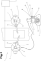
- eine aus mehreren Maschinen, insbesondere Industrierobotern, gebildete technische Anlage und ein dabei eingesetztes, elektronisches Steuerungssystem, welches Steuerungssystem mehrere Steuervorrichtungen und eine Mensch-Maschine-Schnittstelle in Art eines tragbaren Handbediengerätes umfasst;
- Fig. 2
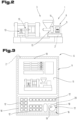
- eine Produktionsmaschine, insbesondere eine Spritzgießmaschine, welche eine elektronische Steuervorrichtung und eine daran angebundene Mensch-Maschine-Schnittstelle in Art eines stationären Bedienpanels umfasst;
- Fig. 3
- das Bedienpanel der Produktionsmaschine nach
Fig. 2 ; - Fig. 4
- eine Steuervorrichtung für industrielle Maschinen mit einem Drehsteller-Bedienelement, welches zur Bedienung oder Beeinflussung von Bewegungsantrieben dient;
- Fig. 5
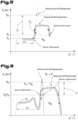
- einen ersten Kennlinienverlauf hinsichtlich Betätigungsmoment und Verdrehwinkel eines Betätigungsorgans eines Drehsteller-Bedienelements mit einem Hemmungs- und einem Blockierverhalten gegenüber dem Betätigungsorgan;
- Fig. 6
- einen zweiten Kennlinienverlauf hinsichtlich Betätigungsmoment und Verdrehwinkel eines Betätigungsorgans eines Drehsteller-Bedienelements mit einem Hemmungs- und einem Blockierverhalten gegenüber dem Betätigungsorgan;
- Fig. 7
- einen dritten Kennlinienverlauf hinsichtlich Betätigungsmoment und Verdrehwinkel eines Betätigungsorgans eines Drehsteller-Bedienelements mit einem Hemmungsverhalten, einem Blockierverhalten und einem kombinierten Hemmungs- und Blockierverhalten gegenüber dem Betätigungsorgan;
- Fig. 8
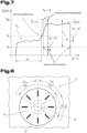
- eine schematische Darstellung eines Betätigungsorgans eines Drehsteller-Bedien- elements, welches zur Nachbildung einer Knebelschalter-Funktion vorgesehen ist und eine virtuelle Rückstellfunktion besitzt.
- Fig. 1
- a technical system made up of several machines, in particular industrial robots, and an electronic control system used Control system comprises a plurality of control devices and a human-machine interface in the form of a portable handheld control device;
- Fig. 2
- a production machine, in particular an injection molding machine, which comprises an electronic control device and a human-machine interface connected to it in the form of a stationary control panel;
- Fig. 3
- the control panel of the production machine
Fig. 2 ; - Fig. 4
- a control device for industrial machines with a rotary actuator control element, which is used to operate or influence motion drives;
- Fig. 5
- a first characteristic curve with regard to the actuation torque and angle of rotation of an actuator of a rotary actuator control element with an inhibition and a blocking behavior relative to the actuator;
- Fig. 6
- a second characteristic curve with regard to the actuation torque and angle of rotation of an actuator of a rotary actuator control element with an inhibition and a blocking behavior relative to the actuator;
- Fig. 7
- a third characteristic curve with regard to the actuation torque and angle of rotation of an actuator of a rotary actuator control element with an inhibition behavior, a blocking behavior and a combined inhibition and blocking behavior relative to the actuator;
- Fig. 8
- a schematic representation of an actuator of a rotary control control element, which is intended to simulate a toggle switch function and has a virtual reset function.
Einführend sei festgehalten, dass in den unterschiedlich beschriebenen Ausführungsformen gleiche Teile mit gleichen Bezugszeichen bzw. gleichen Bauteilbezeichnungen versehen werden, wobei die in der gesamten Beschreibung enthaltenen Offenbarungen sinngemäß auf gleiche Teile mit gleichen Bezugszeichen bzw. gleichen Bauteilbezeichnungen übertragen werden können. Auch sind die in der Beschreibung gewählten Lageangaben, wie z.B. oben, unten, seitlich usw. auf die unmittelbar beschriebene sowie dargestellte Figur bezogen und sind diese Lageangaben bei einer Lageänderung sinngemäß auf die neue Lage zu übertragen.As an introduction, it should be noted that in the differently described embodiments, the same parts are provided with the same reference numbers or the same component names, whereby the disclosures contained in the entire description can be transferred analogously to the same parts with the same reference numbers or the same component names. The position information selected in the description, such as top, bottom, side, etc., is also related to the figure directly described and shown and, in the event of a change in position, these position information must be transferred accordingly to the new position.
In den
Entsprechend der Ausführung nach
Zumindest einer Steuervorrichtung 2' in zumindest einer Maschine 3 ist dabei zumindest eine Mensch-Maschine-Schnittstelle 6 (HMI) zugeordnet bzw. zuordenbar. Mittels dieser Mensch-Maschine-Schnittstelle 6 sind steuerungsrelevante Interaktionen zwischen einer Bedienperson 7 und der jeweiligen Maschine 3 ermöglicht.At least one human-machine interface 6 (HMI) is assigned or can be assigned to at least one control device 2 'in at least one
Beim Ausführungsbeispiel gemäß
Ein gattungsgemäßes Handbediengerät 8 bzw. Bedienpanel 9 weist wenigstens eine Eingabevorrichtung 10, wie zum Beispiel einen berührungssensitiven Bildschirm 11, Eingabetasten 12, Schalter, oder sonstige elektrische oder elektromechanische Eingabemittel auf. Zudem können visuell und/oder akustisch erfassbare Ausgabemittel vorgesehen sein. Bei einem gattungsgemäßen Handbediengerät 8 bzw. Bedienpanel 9 können insbesondere der zuvor erwähnte berührungssensitive Bildschirm 11, sowie Leuchtelemente bzw. Signalisierungslampen zur Anzeige von systemrelevanten Daten bzw. Zuständen vorgesehen sein. Der Funktionsumfang und die Ausführungsform der jeweiligen Eingabevorrichtung bzw. der jeweiligen Ausgabevorrichtung hängen dabei stark von der jeweiligen Anwendung, insbesondere von der technischen Komplexität der zu steuernden Maschine 3 bzw. Anlage ab. Wesentlich ist dabei, dass die Bedienperson 7 mittels der Eingabevorrichtung 10 und einer geeigneten Ausgabevorrichtung, insbesondere mittels dem zuvor genannten berührungssensitiven Bildschirm 11, die benötigten steuerungstechnischen Abläufe kontrollieren bzw. überwachen, beeinflussen und/oder programmieren kann.A generic handheld control device 8 or control panel 9 has at least one
Die in der Mensch-Maschine-Schnittstelle 6, insbesondere im Handbediengerät 8 bzw. im Bedienpanel 9 ausgeführte Steuervorrichtung 2 und die einer Maschine 3 zugeordnete Steuervorrichtung 2' können dabei über kabelgebundene und/oder drahtlos ausgeführte Kommunikationsschnittstellen in datentechnischer bzw. steuerungstechnischer Wechselwirkung stehen.The
Wie an sich bekannt, sind zur Automatisierung der jeweiligen Maschinen 3 steuerbare, insbesondere wenigstens aktivier- und deaktivierbare Bewegungsantriebe 13 vorgesehen, welche mit der jeweiligen Steuervorrichtung 2' leitungsverbunden sind. Häufig sind solche Bewegungsantriebe 13 auch hinsichtlich ihrer Antriebsgeschwindigkeit und/oder Antriebsleistung bzw. Antriebskraft bedarfsabhängig einstell- bzw. veränderbar. Derartige Bewegungsantriebe 13 können, wie in
Zur manuellen Beeinflussung bzw. zur Programmierung der jeweiligen Bewegungsantriebe 13 bzw. Maschinenkomponenten ist an der jeweiligen Mensch-Maschine-Schnittstelle 6 zumindest ein Bedienelement 16 zur manuellen Beeinflussung oder Vorgabe von Verstellbewegungen von zumindest einer der Maschinenkomponenten bzw. Maschinenachsen vorgesehen. Diese manuelle Beeinflussung oder Vorgabe von Verstellbewegungen durch eine Bedienperson 7 umfasst vorzugsweise die Möglichkeit einer Geschwindigkeits- und/oder Leistungsveränderung des anzusteuernden bzw. selektiv ansteuerbaren Bewegungsantriebes 13. Zudem können Bedienelemente, insbesondere Tast- oder Schaltelemente, ausgeführt sein, welche zur Aktivierung und Deaktivierung eines ausgewählten bzw. ansteuerbaren Bewegungsantriebes 13 vorgesehen sind.To manually influence or program the respective movement drives 13 or machine components, at least one
Zumindest eines der Bedienelemente 16 an der Mensch-Maschine-Schnittstelle 6 ist dabei als Drehsteller-Bedienelement 17 mit einem endlos bzw. anschlaglos verdrehbaren Betätigungsorgan 18 ausgeführt. Endlose Verdrehbarkeit bedeutet dabei, dass das Drehsteller-Bedienelement 17 bzw. dessen Betätigungsorgan 18 derart ausgeführt ist, dass es keine mechanischen Endanschläge bzw. keine dauerhafte Begrenzung hinsichtlich der Drehbeweglichkeit des Betätigungsorgans 18 gibt. Dies im Unterschied zu einem typischen Potentiometer bzw. einstellbaren, ohmschen Widerstand, bei welchem ein Verdreh- bzw. Einstellbereich von üblicherweise etwa 270° gegeben ist. Das anspruchsgemäße Drehsteller-Bedienelement 17 ist vielmehr mit einem sogenannten Override-Potentiometer vergleichbar bzw. kann das Drehsteller-Bedienelement 17 als endlos drehbeweglicher Inkrementalgeber ausgeführt sein. Vorteilhaft ist es dabei, wenn das Drehsteller-Bedienelement 17 eine endlose Rotierbarkeit seines beispielsweise scheiben- oder radförmigen Betätigungsorgans 18 bzw. eine damit einhergehende, unbegrenzte Abgabe von Sensorimpulsen bzw. Inkrementen ermöglicht.At least one of the
Optional kann das Betätigungsorgan 18 wenigstens eine Markierung 19 umfassen, mit welcher einer Bedienperson 7 die jeweilige Drehwinkelstellung des Betätigungsorgans 18 angezeigt werden kann. Eine solche Markierung 19 am vorzugsweise endlos verdrehbaren bzw. anschlaglos rotierbaren Betätigungsorgan 18 ist jedoch nicht zwingend.Optionally, the actuating
Das Drehsteller-Bedienelement 17 ist mit einer elektronischen Auswerte- und Steuervorrichtung 20 verbunden bzw. kann eine solche Auswerte- und Steuervorrichtung 20 ein Bestandteil des Drehsteller-Bedienelementes 17 sein. Insbesondere sind Signale bzw. Betätigungszustände des Drehsteller-Bedienelementes 17 durch die Auswerte- und Steuervorrichtung 20 erfass- und evaluierbar.The
Die Auswerte- und Steuervorrichtung 20 kann dabei als eigenständige bzw. separate Einheit ausgeführt sein, oder aber durch die Steuervorrichtung 2, 2' umgesetzt werden. Insbesondere kann die Steuervorrichtung 2, 2' zumindest Teilaufgaben der Auswerte- und Steuervorrichtung 20 übernehmen. Dies vor allem deshalb, weil die Funktionalitäten der Auswerte- und Steuervorrichtung 20 überwiegend softwaretechnisch bzw. programmtechnisch realisierbar sind und daher in einfacher Art und Weise einen Funktionsumfang der Steuervorrichtung 2, 2` darstellen können. Es ist somit auch ein kombinatorisches Zusammenwirken möglich, um eine Umsetzung der Auswerte- und Steuervorrichtung 20 zu erzielen. Die Auswerte- und Steuervorrichtung 20 kann aber auch - wie vorstehend beschrieben - integraler Bestandteil des Drehsteller-Bedienelementes 17 sein.The evaluation and
Das Drehsteller-Bedienelement 17 umfasst wenigstens ein sensortechnisches Erfassungsmittel 21 zur Ermittlung der von einer Bedienperson 7 jeweils vorgenommenen Drehbetätigungen gegenüber dem Betätigungsorgan 18. Insbesondere ist es möglich, via das sensortechnische Erfassungsmittel 21 zumindest den zurückgelegten Drehwinkel, also die Winkeländerung, und die Drehrichtung des Betätigungsorgans 18 zu detektieren. Als sensortechnisches Erfassungsmittel 21 eigtien sich vorzugsweise Inkrementalgeber oder auch Absolutwertgeber, welche mit der Auswerte- und Steuervorrichtung 20 leitungsverbunden sind und so die jeweiligen Sensorsignale bzw. Werte zur weiteren Verarbeitung bzw. Auswertung bereitstellen. Insbesondere kann via die Auswerte- und Steuervorrichtung 20 das von der Bedienperson 7 gegenüber dem Betätigungsorgan 18 ausgeübte Bedienverhalten ermittelt werden. Das Bedienverhalten umfasst dabei Parameter wie Drehrichtung, Drehwinkel, Drehgeschwindigkeit, Betätigungs- bzw. Drehverlauf, Winkelbeschleunigung und dergleichen. Daraus folgt, dass die von einer Bedienperson 7 am Betätigungsorgan 18 respektive gegenüber seiner Drehachse 22 ausgeübten Drehbewegungen von der elektronischen Auswerte- und Steuervorrichtung 20 evaluiert werden und daraus entsprechende Steuerbefehle für die angesteuerte Maschine 3 bzw. Maschinenkomponente abgeleitet werden.The rotary
Das Betätigungsorgan 18 oder dessen Drehachse 22 steht mit einem gesteuert veränderlichen Drehwiderstand-Generierungsmittel 23 in mechanischer Wechselwirkung bzw. ist das Drehwiderstand-Generierungsmittel 23 mit der Drehachse 22 des Betätigungsorgans 18 bewegungsgekoppelt. Die Auswerte- und Steuervorrichtung 20 ist dabei mit dem Drehwiderstand-Generierungsmittel 23 leitungsverbunden und zur gesteuert veränderlichen Einstellung von Drehwiderständen des Drehwiderstand-Generierungsmittels 23 ausgebildet. Das Drehwiderstand-Generierungsmittel 23 kann dabei eine elektrorheologische oder magnetorheologische Flüssigkeit umfassen, deren Viskosität durch Einwirkung elektrischer Energie in Form von elektrischen oder elektromagnetischen Feldern beeinflussbar ist. Dadurch kann der Bedienperson 7 in steuerungstechnisch einfacher und zuverlässiger Art und Weise ein variantenreiches bzw. situationsgerecht anpassbares, haptisches Feedback in Zusammenhang mit der Bedienung des Betätigungsorgans 18 gegeben werden. Ein derartiges Feedback kann Raststufen und/oder gesteuert variierende Betätigungs- bzw. Verdrehwiderstände umfassen.The
Die zumindest teilweise softwaretechnisch umgesetzte Auswerte- und Steuervorrichtung 20 ist unter anderem zur Bereitstellung eines Knebelschalter-Betriebsmodus des Drehsteller-Bedienelementes 17 bzw. der Steuervorrichtung 2, 2' eingerichtet. Ein beispielhaftes Verhalten des Drehsteller-Bedienelementes 17 in diesem Knebelschalter-Betriebsmodus ist in den
Eine schematische Darstellung eines beispielhaften Drehsteller-Bedienelements 17, welches zumindest einen Knebelschalter-Betriebsmodus bereitstellen kann, ist in
Die Schaltfunktionen des Drehsteller-Bedienelementes 17 können somit als Rast-Schalfunktionen und/oder als Tast-Schalfunktionen umgesetzt sein. Zudem kann die Auswerte- und Steuervorrichtung 20 zur Bereitstellung eines ersten Knebelschalter-Betriebsmodus eingerichtet sein, in welchem eine Drehbetätigung bzw. Verdrehbarkeit des Betätigungsorgans 18 in nur eine Drehrichtung freigegeben ist. Dies entspricht einer Nachbildung eines zweistufigen Knebelschalters mit virtueller Null- bzw. Inaktiv-Stellung und einer dazu um einen Verdrehwinkel ---ui bzw. -α1 distanzierten Schalt- bzw. Aktivstellung.The switching functions of the rotary
Alternativ oder in Kombination dazu kann die Auswerte- und Steuervorrichtung 20 zur Bereitstellung eines zweiten Knebelschalter-Betriebsmodus eingerichtet sein, in welchem eine Drehbetätigung des Betätigungsorgans 18 in beide Drehrichtungen zugelassen bzw. ermöglicht ist, wie dies in
Wesentlich ist dabei, dass die zuletzt eingenommene Drehwinkelstellung nach einem Wegfall des von der Bedienperson ausgeübten Betätigungsmoments Mu gegenüber dem Bedienelement 18 eine neue Ausgangsposition bzw. eine virtuelle Nullstellung für einen nachfolgenden Knebelschalter-Betriebsmodus bzw. für eine nächste Knebelschalter-Bedienhandlung durch die Bedienperson definiert. Beim angegebenen Drehsteller-Bedienelement 17 erfolgt also keine physische Rückstellung des Betätigungsorgans 18 in eine vordefinierte Ruhe- bzw. Nullstellung. Insbesondere ist weder eine Federrückstellung, noch eine motorische oder sonstige Rückstellung des Betätigungsorgans 18 nach erfolgter, manueller Drehbetätigung vorgesehen. Vielmehr verbleibt das Betätigungsorgan 18 stets in jenen Drehwinkelstellungen, welche von der Bedienperson durch eine Drehbetätigung aktiv hergestellt bzw. bewirkt wurden. Demnach weist das erfindungsgemäße Drehsteller-Bedienelement 17 bzw. dessen Betätigungsorgan keine fix vordefinierte Ausgangsposition bzw. Null stellung auf, sondern eine Vielzahl von virtuellen bzw. steuerungstechnisch bestimmten Ausgangspositionen bzw. Nullstellungen, welche durch unterschiedliche bzw. variable Drehwinkelstellungen des Betätigungsorgans 18 definiert sind. Beispiele für eine Mehrzahl von virtuellen Nullstellungen bzw. variablen Ausganspositiotien und Beispiele für über einen Verdrehwinkel +α1 bzw. - α1 aktivierbare bzw. für hierzu entfernt liegende Schalt- bzw. Aktivstellungen sind in
Insbesondere dann, wenn das Drehwiderstand-Generierungsmittel 23 eine weitere Verdrehbarkeit des Betätigungsorgans 18 bzw. von dessen Drehachse 22 nach dem Erreichen des steuerungstechnisch vordefinierten Verdrehwinkels +α1 oder - α1 blockiert, kann die temporär wirkende Aktiv- bzw. Schaltstellung des Drehsteller-Bedienelements 18 nachfolgend eine neue Ausgangsposition bzw. eine virtuelle Nullstellung für eine nächste Bedienhandlung bzw. für eine anschließende Betätigung oder für eine weitere Aktivierung des Drehsteller-Bedienelementes 17 von Seiten der Bedienperson sein.In particular, if the rotational resistance generating means 23 blocks further rotation of the actuating
Grundsätzlich ist vorgesehen, dass das Drehwiderstand-Generierungsmittel 23 von der Auswerte- und Steuervorrichtung 20 derart ansteuerbar ist, dass das Drehwiderstand-Generierungsmittel 23 nach Zurücklegung bzw. kurz vor Zurücklegung eines vordefinierten Verdrehwinkels +α1 bzw. -α1 des Betätigungsorgans 18 ein Brems- und/oder Blockiermoment MBR, MBL aufbaut oder erzeugt, wie dies in den
Der Verdrehwinkel +α1 bzw. -α1 ist vorzugsweise vordefiniert und kann einen Wert innerhalb eines Wertebereiches zwischen 10° und 90° aufweisen. Entsprechend einer praktikablen Ausführung liegt der vordefinierte Verdrehwinkel -α1 bzw. -α1 in einem Bereich zwischen etwa 30° und etwa 60°, beispielsweise bei etwa 45°, um eine möglichst komfortable bzw. intuitive Betätigung des Drehsteller-Bedienelementes 17 zu ermöglichen. Der steuerungstechnisch vordefinierte Verdrehwinkel +α1 bzw. -α1 kann beispielsweise in der Auswerte- und Steuervorrichtung 20 hinterlegt sein und mittels dem sensortechnischen Erfassungsmittel 21, beispielsweise via einen entsprechenden Inkrementalgeber, von der Auswerte- und Steuervorrichtung 20 erfasst bzw. kontrolliert werden.The twist angle +α 1 or -α 1 is preferably predefined and can have a value within a value range between 10° and 90°. According to a practical embodiment, the predefined twist angle -α 1 or -α 1 is in a range between approximately 30° and approximately 60°, for example approximately 45°, in order to enable the rotary
Um eine Verdrehung bzw. eine Drehwinkeländerung des Betätigungsorgans 18 bewirken zu können, wird von der Bedienperson eine Betätigungsmoment MU aufgebracht, welches dem vom Drehwiderstand-Generierungsmittel 23 generierten bzw. gesteuert generierbaren Brems- und/oder Blockiermoment MBR, MBL entgegenwirkt bzw. das jeweils einwirkende Bremsmoment MBR überwindet. Beispiele für ein variierendes Betätigungsmoment MU, welches sich in Bezug auf eine Zeitspanne bzw. in Bezug auf einen sich zeitlich verändernden Verdrehwinkel α verändert, sind in den
Das von der Bedienperson aufgebrachte bzw. aufzubringende Betätigungsmoment MU bzw. dessen drehwinkelabhängiger Verlauf ist dabei in den
Das von der Auswerte- und Steuervorrichtung 20 gegebenenfalls vorgegebene bzw. veranlasste und vom Drehwiderstand-Generierungsmittel 23 generierte Blockiermoment MBL ist vorzugsweise derart hoch, dass für die Bedienperson klar erkennbar ist, dass eine weitere Verdrehbarkeit des Betätigungsorgans 18 nicht vorgesehen ist bzw. die Verdrehbarkeit als gesperrt zu betrachten ist. Dabei ist zu berücksichtigen, dass das steuerbare Drehwiderstand-Generierungsmittel 23 selbstverständlich nur ein endliches bzw. begrenztes Blockiermoment MBL erzeugen bzw. bereitstellen kann. Das Blockiermoment MBL des Drehwiderstand-Generierungsmittels 23 gegenüber dem Betätigungsorgan 18 ist jedoch derart hoch, dass es im Zuge der Bedienhandlungen von der Bedienperson deutlich wahrnehmbar bzw. eindeutig spürbar ist.The blocking torque M BL , which may be specified or caused by the evaluation and
Wie aus den Betätigungsmoment- zu Drehwinkel-Verläufen Mu (Nm) / α (°, rad) der beispielhaften
Der Deaktivierungs-Schwellwert MD kann somit in einem Wertebereich zwischen Null und kleiner dem Wert des maximal möglichen bzw. aufbringbaren Blockiermoments MBL sein. Zweckmäßigerweise liegt der Deaktivierungs-Schwellwert MD in einem Bereich zwischen 10% und 90%, vorzugsweise zwischen 10% und 60% des maximal aufbringbaren Blockiermoments MBL .The deactivation threshold value M D can therefore be in a value range between zero and less than the value of the maximum possible or achievable blocking torque M BL . The deactivation threshold M D is expediently in a range between 10% and 90%, preferably between 10% and 60% of the maximum blocking torque M BL that can be applied.
Wie vorhergehend dargelegt, liegt der vordefinierte Verdrehwinkel +α1 bzw. -α1 zweckmäßigerweise bei einem Wert zwischen 10° und 90°, bevorzugt zwischen 20° und 60°, besonders bevorzugt zwischen 30° und 50°. Dadurch wird eine möglichst ergonomische Bedienung des Betätigungsorgans 18 erreicht.As explained above, the predefined twist angle +α 1 or -α 1 is expediently at a value between 10° and 90°, preferably between 20° and 60°, particularly preferably between 30° and 50°. This results in the most ergonomic operation of the
Zweckmäßig ist es, wenn für das Erreichen bzw. bis zum Erreichen des vordefinierten Verdrehwinkels +α1 bzw. -α1 vom Drehwiderstand-Generierungsmittel 23 ein definierter Verdrehwiderstand, d.h. eine definiertes Gegen- bzw. Bremsmoment MBR aufgebaut ist, wie dies den
Beim Ausführungsbeispiel nach
Wie den
Bei Wegfall oder starkem Abfall des Betätigungsmoments Mu, wie dies in den
Wesentlich ist, dass das Betätigungsorgan 18 bei einem Wegfall des von der Bedienperson aufgebrachten Betätigungsmoments Mu an der jeweiligen Stelle verbleibt, d.h. seinen Drehwinkel nicht verändert sondern beibehält. Insbesondere erfolgt keine automatische Rückstellung, beispielsweise durch Federwirkung oder durch Motoren, sondern verbleibt das Betätigungsorgan 18 an der zuletzt geltenden Aktiv- bzw. Schaltstellung nach einer zuvor erfolgten Zurücklegung des vordefinierten Verdrehwinkels +α1 bzw. -α1, d.h. nach einem Aufbringen der hierfür erforderlichen Betätigungskraft bzw. Betätigungsenergie durch eine Bedienperson. Insbesondere definiert die zuletzt eingenommene Drehwinkelstellung nach einem Wegfall des von der Bedienperson ausgeübten Betätigungsmoments Mu eine Ausgangsposition oder eine virtuelle Nullstellung für eine nachfolgende Verwendung als simulierter Knebelschalter bzw. für einen anschließenden, erneut nachgeahmten Knebelschalter-Betriebsmodus, wie dies in
Entsprechend einer praktikablen Maßnahme kann vorgesehen sein, dass das von der Bedienperson ausgeübte Betätigungsmoment Mu gegenüber dem Betätigungsorgan 18 durch Messen oder Berechnen jener elektrischen Energiemenge oder Leistung detektiert oder ermittelt ist, welche aufzuwenden oder aufzubringen ist, um das in Korrelation zum zurückgelegten Verdrehwinkel +α1 bzw. -α1 des Betätigungsorgans 18 jeweils benötigte oder aufzubringende Bremsmoment MBR erzeugen zu können. Insbesondere ist der durch die Auswerte- und Steuervorrichtung 20 vordefinierte Brems- oder Blockiermoment-Verlauf, wie er in den
Wie den
Wir vor allem den
Der Drift-Wertebereich 24 oder der Drift-Schwellwert kann derart gewählt sein, dass ein Weiterdrehen des Betätigungsorgans 18 mit einer Verdrehgeschwindigkeit von weniger als 5 °/s (Winkelgrad pro Sekunde), vorzugsweise von weniger als 1 °/s ermöglicht bzw. steuerungstechnisch zugelassen ist.The
Wie am besten dem Kennlinien-Verlauf gemäß
Die Ausführungsbeispiele zeigen mögliche Ausführungsvarianten, wobei an dieser Stelle bemerkt sei, dass die Erfindung nicht auf die speziell dargestellten Ausführungsvarianten derselben eingeschränkt ist, sondern vielmehr auch diverse Kombinationen der einzelnen Ausführungsvarianten untereinander möglich sind und diese Variationsmöglichkeit aufgrund der Lehre zum technischen Handeln durch gegenständliche Erfindung im Können des auf diesem technischen Gebiet tätigen Fachmannes liegt.The exemplary embodiments show possible embodiment variants, whereby it should be noted at this point that the invention is not limited to the specifically illustrated embodiment variants, but rather various combinations of the individual embodiment variants with one another are possible and this variation possibility is based on the teaching on technical action through the subject invention Skills of the specialist working in this technical field.
Der Schutzbereich ist durch die Ansprüche bestimmt. Die Beschreibung und die Zeichnungen sind jedoch zur Auslegung der Ansprüche heranzuziehen. Einzelmerkmale oder Merkmalskombinationen aus den gezeigten und beschriebenen unterschiedlichen Ausführungsbeispielen können für sich eigenständige erfinderische Lösungen darstellen. Die den eigenständigen erfinderischen Lösungen zugrundeliegende Aufgabe kann der Beschreibung entnommen werden.The scope of protection is determined by the claims. However, the description and drawings must be used to interpret the claims. Individual features or combinations of features from the different exemplary embodiments shown and described can represent independent inventive solutions in their own right. The task underlying the independent inventive solutions can be found in the description.
Sämtliche Angaben zu Wertebereichen in gegenständlicher Beschreibung sind so zu verstehen, dass diese beliebige und alle Teilbereiche daraus mitumfassen, z.B. ist die Angabe 1 bis 10 so zu verstehen, dass sämtliche Teilbereiche, ausgehend von der unteren Grenze 1 und der oberen Grenze 10 mit umfasst sind, d.h. sämtliche Teilbereiche beginnen mit einer unteren Grenze von 1 oder größer und enden bei einer oberen Grenze von 10 oder weniger, z.B. 1 bis 1,7, oder 3,2 bis 8,1, oder 5,5 bis 10.All information on value ranges in this description should be understood to include any and all sub-ranges, e.g. the
Der Ordnung halber sei abschließend darauf hingewiesen, dass zum besseren Verständnis des Aufbaus Elemente teilweise unmaßstäblich und/oder vergrößert und/oder verkleinert dargestellt wurden.For the sake of order, it should finally be pointed out that in order to better understand the structure, elements have sometimes been shown out of scale and/or enlarged and/or reduced in size.
Claims (13)
- A control device (2, 2') for industrial machines with controlled movement drives (13) for machine components, comprising a man-machine interface (6) with at least one operating element (16) for manually influencing or presetting adjustment movements of at least one of the machine components, wherein at least one operating element (16) is configured as a rotary actuator operating element (17) with an actuation member (18) supported being rotatable about an axis of rotation (22), which actuation member (18) can be rotated by the application of an actuating torque (MB) by an operator, wherein the actuation member (18) or its axis of rotation (22) is in mechanical interaction with a controlled variable means generating rotational resistance (23) or is motion-coupled thereto, wherein an electronic evaluation and control device (20) is configured for the variable setting of rotational resistances of the means generating rotational resistance (23), characterized in that the evaluation and control device (20) is configured to provide at least one toggle switch operating mode, in which the means generating rotational resistance (23) can be controlled by the evaluation and control device (20) in such a way that the means generating rotational resistance (23) builds up or generates a braking or blocking torque (MBR, MBL) after a predefined angle of rotation (α1) of the actuation member (18) has been covered, which inhibits, increasingly inhibits or prevents further rotatability of the actuation member (18), wherein a switching state of the rotary actuator operating element (17) is activated or is deemed to be activated, as long as an actuating torque (Mu) of the operator acting against the braking or blocking torque (MBR, MBL) is equal to the blocking torque (MB) or corresponds to the blocking torque (MB) or exceeds a comparatively lower deactivation threshold value (MD), and that the switching state of the rotary actuator operating element (17) is inactive or is deemed to be deactivated when the actuating torque (Mu) exerted by the operator falls below the deactivation threshold value (MD) or is zero.
- The control device according to claim 1, characterized in that the means generating rotational resistance (23) comprises an electrorheological or magnetorheological fluid the viscosity of which can be influenced by the action of electrical energy in the form of electric or electromagnetic fields.
- The control device according to claim 1 or 2, characterized in that when the predefined angle of rotation (α1) of the actuation member (18) is reached, a braking torque (MBR) at least at the level of a predefined activation threshold value (MA) is built up by the means generating rotational resistance (23), which braking torque (MBR) is lower than its maximum blocking torque (MBL), wherein the switching state of the rotary actuator operating element (17) is activated or is deemed to be activated while and as long as the actuating torque (Mu) applied by the operator exceeds the predefined activation threshold value (MA) or the predefined deactivation threshold value (MD).
- The control device according to one of the preceding claims, characterized in that the actuating torque (Mu) exerted by the operator with respect to the actuation member (18) is detected or determined by measuring or calculating that amount of electrical energy or power which is to be expended or applied, in order to be able to generate the braking torque (MBR) required or to be applied in correlation with the angle of rotation (α1) traveled by the actuation member (18), which is required in accordance with the braking or blocking torque curve of the actuation member (18) predefined by the evaluation and control device (20), or is to be provided by the means generating rotational resistance (23).
- The control device according to one of the preceding claims, characterized in that the predefined angle of rotation (α1) is an absolute angle of rotation which is dimensioned independently of an initial angular position of the actuation member (18).
- The control device according to one of the preceding claims, characterized in that, when the actuating torque (Mu) exerted by the operator ceases, the actuation member (18) retains the rotational angle position assumed at this point in time.
- The control device according to one of the preceding claims, characterized in that the rotational angle position last assumed after the actuating torque (Mu) exerted by the operator has ceased defines an initial position or a virtual zero position for subsequent use as a simulated toggle switch.
- The control device according to one of the preceding claims, characterized in that the evaluation and control device (20) is configured to provide a first toggle switch operating mode, in which a rotary actuation of the actuation member (18) in only one direction of rotation is enabled.
- The control device according to one of the preceding claims, characterized in that the evaluation and control device (20) is configured to provide a second toggle switch operating mode in which a rotary actuation of the actuation member (18) in both directions of rotation is permitted.
- The control device according to one of the preceding claims, characterized in that the evaluation and control device (20) is configured to control the means generating rotational resistance (23) in such a way that upon performed coverage or after coverage of the predefined angle of rotation (α1) of the actuation member (18), and the associated presence of a rotational angle position, in which the rotary actuator operating element (17) signals or assumes an active switching state, the braking torque (MBR) of the means generating rotational resistance (23) is held in a drift value range (24) or at a drift threshold value which permits or enables a comparatively slower or more sluggish further rotation of the actuation member (18) counter to the braking torque (MBR) of the means generating rotational resistances (23).
- The control device according to claim 10, characterized in that the drift value range (24) or the drift threshold value is selected in such a way that further rotation of the actuation member (18) at a rotational speed of less than 5 °/s (angular degrees per second), preferably of less than 1 °/s, is made possible.
- The control device according to one of the preceding claims, characterized in that the evaluation and control device (20) is configured to control the means generating rotational resistance (23) in such a way that before reaching or in the course of reaching the predefined angle of rotation (α1) of the actuation member (18) and the associated presence of an rotational angle position, in which the rotary actuator operating element (17) signals or assumes an active switching state, the braking torque (MBR) of the means generating rotational resistance (23) is lowered or deactivated with respect to a rotational angle range of up to 10° (angular degrees) and is subsequently raised to a value which enables blocking or a comparatively slower rotatability of the actuation member (18).
- The control device according to one of the preceding claims, characterized in that the actuation member (18) is mechanically supported without a stop and can be rotated endlessly if or as long as no blocking torque (MBL) is generated by the means generating rotational resistance (23).
Applications Claiming Priority (2)
| Application Number | Priority Date | Filing Date | Title |
|---|---|---|---|
| AT506412017 | 2017-08-01 | ||
| PCT/AT2018/060167 WO2019023727A2 (en) | 2017-08-01 | 2018-07-27 | Control device for industrial machines |
Publications (2)
| Publication Number | Publication Date |
|---|---|
| EP3662345A2 EP3662345A2 (en) | 2020-06-10 |
| EP3662345B1 true EP3662345B1 (en) | 2023-12-13 |
Family
ID=63491357
Family Applications (1)
| Application Number | Title | Priority Date | Filing Date |
|---|---|---|---|
| EP18765351.4A Active EP3662345B1 (en) | 2017-08-01 | 2018-07-27 | Control device for industrial machines |
Country Status (3)
| Country | Link |
|---|---|
| EP (1) | EP3662345B1 (en) |
| JP (1) | JP7232243B2 (en) |
| WO (1) | WO2019023727A2 (en) |
Families Citing this family (2)
| Publication number | Priority date | Publication date | Assignee | Title |
|---|---|---|---|---|
| US11786956B2 (en) | 2021-05-14 | 2023-10-17 | Stolle Machinery Company, Llc | System and method for automated low-speed positioning of a can necking machine |
| EP4137898B1 (en) * | 2021-08-20 | 2024-04-17 | Siemens Aktiengesellschaft | Control device for a cnc control system |
Citations (1)
| Publication number | Priority date | Publication date | Assignee | Title |
|---|---|---|---|---|
| EP1403619B1 (en) * | 2002-09-27 | 2007-12-19 | Robert Bosch Gmbh | Input device |
Family Cites Families (7)
| Publication number | Priority date | Publication date | Assignee | Title |
|---|---|---|---|---|
| DE10029191A1 (en) | 2000-06-19 | 2001-12-20 | Philips Corp Intellectual Pty | Haptic control element e.g. for vehicle instrument panel, has gap between electronically controled rotary knob, magnetic circuit filled with magnetorheological liquid, and coil for producing variable braking effect on knob |
| JP2005019113A (en) | 2003-06-25 | 2005-01-20 | Alps Electric Co Ltd | Tactile force applying type input device |
| JP4430988B2 (en) | 2004-06-24 | 2010-03-10 | アルプス電気株式会社 | Haptic input device |
| ES2333364T3 (en) | 2005-07-01 | 2010-02-19 | Preh Gmbh | ROTARY ACTUATOR WITH MAGNETIC BRAKE. |
| JP5666375B2 (en) | 2010-09-21 | 2015-02-12 | 株式会社東海理化電機製作所 | Shifting operation device |
| FR3010548B1 (en) * | 2013-09-09 | 2016-12-23 | Dav | HAPTIC RETURN CONTROL INTERFACE |
| CN104908046B (en) * | 2015-06-16 | 2017-01-11 | 东南大学 | Hand controller based on rotary knob type force feedback and mechanical arm remote operating control method |
-
2018
- 2018-07-27 JP JP2020505801A patent/JP7232243B2/en active Active
- 2018-07-27 WO PCT/AT2018/060167 patent/WO2019023727A2/en unknown
- 2018-07-27 EP EP18765351.4A patent/EP3662345B1/en active Active
Patent Citations (1)
| Publication number | Priority date | Publication date | Assignee | Title |
|---|---|---|---|---|
| EP1403619B1 (en) * | 2002-09-27 | 2007-12-19 | Robert Bosch Gmbh | Input device |
Also Published As
| Publication number | Publication date |
|---|---|
| WO2019023727A3 (en) | 2019-03-28 |
| EP3662345A2 (en) | 2020-06-10 |
| WO2019023727A2 (en) | 2019-02-07 |
| JP7232243B2 (en) | 2023-03-02 |
| JP2020529677A (en) | 2020-10-08 |
Similar Documents
| Publication | Publication Date | Title |
|---|---|---|
| EP3512669B1 (en) | Control device and control method for industrial machines having controlled movement drives | |
| EP2709803B2 (en) | Method for influencing movements of a machine or facility in a manually controlled manner and corresponding machine control system | |
| EP2664971B1 (en) | Touch-screen with analogue pressure sensor for an industrial technical equipment | |
| EP3359348B1 (en) | Robot system and method for controlling a robot system | |
| WO2015168716A1 (en) | Operating device and control system | |
| EP3662345B1 (en) | Control device for industrial machines | |
| EP3513261B1 (en) | Control device for operating a machine tool, in particular a milling machine or lathe, and corresponding machine tool | |
| EP3513259B1 (en) | Control device and control method for industrial machines with controlled motion drives | |
| EP3990231A1 (en) | System for performing an input on a robotic manipulator | |
| EP3662346B1 (en) | Control device for industrial machines | |
| EP3688549B1 (en) | Shifting device | |
| WO2005029983A1 (en) | Operating unit for a machine in the tobacco-processing industry | |
| EP3513260B1 (en) | Control device and control method for industrial machines having controlled movement drives | |
| EP3980224B1 (en) | Safety switch element for machines or robots | |
| DE102004013130B4 (en) | Input device for operating a tool or production machine | |
| EP4137898B1 (en) | Control device for a cnc control system | |
| EP4038457A1 (en) | Safety switching device and operating apparatus for robots or other machines | |
| WO2024064989A1 (en) | Display device and control system for potentially dangerous technical systems | |
| DE202018102255U1 (en) | Manual control unit with function switch |
Legal Events
| Date | Code | Title | Description |
|---|---|---|---|
| STAA | Information on the status of an ep patent application or granted ep patent |
Free format text: STATUS: UNKNOWN |
|
| STAA | Information on the status of an ep patent application or granted ep patent |
Free format text: STATUS: THE INTERNATIONAL PUBLICATION HAS BEEN MADE |
|
| PUAI | Public reference made under article 153(3) epc to a published international application that has entered the european phase |
Free format text: ORIGINAL CODE: 0009012 |
|
| STAA | Information on the status of an ep patent application or granted ep patent |
Free format text: STATUS: REQUEST FOR EXAMINATION WAS MADE |
|
| 17P | Request for examination filed |
Effective date: 20200228 |
|
| AK | Designated contracting states |
Kind code of ref document: A2 Designated state(s): AL AT BE BG CH CY CZ DE DK EE ES FI FR GB GR HR HU IE IS IT LI LT LU LV MC MK MT NL NO PL PT RO RS SE SI SK SM TR |
|
| AX | Request for extension of the european patent |
Extension state: BA ME |
|
| DAV | Request for validation of the european patent (deleted) | ||
| DAX | Request for extension of the european patent (deleted) | ||
| STAA | Information on the status of an ep patent application or granted ep patent |
Free format text: STATUS: EXAMINATION IS IN PROGRESS |
|
| 17Q | First examination report despatched |
Effective date: 20210728 |
|
| RAP1 | Party data changed (applicant data changed or rights of an application transferred) |
Owner name: KEBA INDUSTRIAL AUTOMATION GMBH |
|
| GRAP | Despatch of communication of intention to grant a patent |
Free format text: ORIGINAL CODE: EPIDOSNIGR1 |
|
| STAA | Information on the status of an ep patent application or granted ep patent |
Free format text: STATUS: GRANT OF PATENT IS INTENDED |
|
| INTG | Intention to grant announced |
Effective date: 20230713 |
|
| GRAS | Grant fee paid |
Free format text: ORIGINAL CODE: EPIDOSNIGR3 |
|
| GRAA | (expected) grant |
Free format text: ORIGINAL CODE: 0009210 |
|
| STAA | Information on the status of an ep patent application or granted ep patent |
Free format text: STATUS: THE PATENT HAS BEEN GRANTED |
|
| AK | Designated contracting states |
Kind code of ref document: B1 Designated state(s): AL AT BE BG CH CY CZ DE DK EE ES FI FR GB GR HR HU IE IS IT LI LT LU LV MC MK MT NL NO PL PT RO RS SE SI SK SM TR |
|
| REG | Reference to a national code |
Ref country code: GB Ref legal event code: FG4D Free format text: NOT ENGLISH |
|
| REG | Reference to a national code |
Ref country code: CH Ref legal event code: EP |
|
| REG | Reference to a national code |
Ref country code: DE Ref legal event code: R096 Ref document number: 502018013811 Country of ref document: DE |
|
| REG | Reference to a national code |
Ref country code: IE Ref legal event code: FG4D Free format text: LANGUAGE OF EP DOCUMENT: GERMAN |
|
| PG25 | Lapsed in a contracting state [announced via postgrant information from national office to epo] |
Ref country code: GR Free format text: LAPSE BECAUSE OF FAILURE TO SUBMIT A TRANSLATION OF THE DESCRIPTION OR TO PAY THE FEE WITHIN THE PRESCRIBED TIME-LIMIT Effective date: 20240314 |
|
| REG | Reference to a national code |
Ref country code: LT Ref legal event code: MG9D |
|
| PG25 | Lapsed in a contracting state [announced via postgrant information from national office to epo] |
Ref country code: LT Free format text: LAPSE BECAUSE OF FAILURE TO SUBMIT A TRANSLATION OF THE DESCRIPTION OR TO PAY THE FEE WITHIN THE PRESCRIBED TIME-LIMIT Effective date: 20231213 |
|
| REG | Reference to a national code |
Ref country code: NL Ref legal event code: MP Effective date: 20231213 |
|
| PG25 | Lapsed in a contracting state [announced via postgrant information from national office to epo] |
Ref country code: ES Free format text: LAPSE BECAUSE OF FAILURE TO SUBMIT A TRANSLATION OF THE DESCRIPTION OR TO PAY THE FEE WITHIN THE PRESCRIBED TIME-LIMIT Effective date: 20231213 |
|
| PG25 | Lapsed in a contracting state [announced via postgrant information from national office to epo] |
Ref country code: LT Free format text: LAPSE BECAUSE OF FAILURE TO SUBMIT A TRANSLATION OF THE DESCRIPTION OR TO PAY THE FEE WITHIN THE PRESCRIBED TIME-LIMIT Effective date: 20231213 Ref country code: GR Free format text: LAPSE BECAUSE OF FAILURE TO SUBMIT A TRANSLATION OF THE DESCRIPTION OR TO PAY THE FEE WITHIN THE PRESCRIBED TIME-LIMIT Effective date: 20240314 Ref country code: ES Free format text: LAPSE BECAUSE OF FAILURE TO SUBMIT A TRANSLATION OF THE DESCRIPTION OR TO PAY THE FEE WITHIN THE PRESCRIBED TIME-LIMIT Effective date: 20231213 Ref country code: BG Free format text: LAPSE BECAUSE OF FAILURE TO SUBMIT A TRANSLATION OF THE DESCRIPTION OR TO PAY THE FEE WITHIN THE PRESCRIBED TIME-LIMIT Effective date: 20240313 |
|
| PG25 | Lapsed in a contracting state [announced via postgrant information from national office to epo] |
Ref country code: NL Free format text: LAPSE BECAUSE OF FAILURE TO SUBMIT A TRANSLATION OF THE DESCRIPTION OR TO PAY THE FEE WITHIN THE PRESCRIBED TIME-LIMIT Effective date: 20231213 |