EP4130659A1 - Agricultural traveling vehicle, control device, and program - Google Patents
Agricultural traveling vehicle, control device, and program Download PDFInfo
- Publication number
- EP4130659A1 EP4130659A1 EP21776910.8A EP21776910A EP4130659A1 EP 4130659 A1 EP4130659 A1 EP 4130659A1 EP 21776910 A EP21776910 A EP 21776910A EP 4130659 A1 EP4130659 A1 EP 4130659A1
- Authority
- EP
- European Patent Office
- Prior art keywords
- ridge
- agricultural vehicle
- point group
- data
- control device
- Prior art date
- Legal status (The legal status is an assumption and is not a legal conclusion. Google has not performed a legal analysis and makes no representation as to the accuracy of the status listed.)
- Pending
Links
- 230000007246 mechanism Effects 0.000 claims description 34
- 238000004891 communication Methods 0.000 claims description 8
- 238000000034 method Methods 0.000 description 10
- 238000010586 diagram Methods 0.000 description 8
- 230000008859 change Effects 0.000 description 6
- 230000008569 process Effects 0.000 description 6
- 230000000694 effects Effects 0.000 description 4
- 230000006870 function Effects 0.000 description 3
- 239000003905 agrochemical Substances 0.000 description 2
- 238000003306 harvesting Methods 0.000 description 2
- 238000005507 spraying Methods 0.000 description 2
- 230000003111 delayed effect Effects 0.000 description 1
- 238000001514 detection method Methods 0.000 description 1
- 239000000284 extract Substances 0.000 description 1
- 238000003384 imaging method Methods 0.000 description 1
- 230000001678 irradiating effect Effects 0.000 description 1
- 230000001788 irregular Effects 0.000 description 1
- 238000005259 measurement Methods 0.000 description 1
- 238000012986 modification Methods 0.000 description 1
- 230000004048 modification Effects 0.000 description 1
- 238000012544 monitoring process Methods 0.000 description 1
- 238000010899 nucleation Methods 0.000 description 1
- 238000012545 processing Methods 0.000 description 1
Images
Classifications
-
- G—PHYSICS
- G05—CONTROLLING; REGULATING
- G05D—SYSTEMS FOR CONTROLLING OR REGULATING NON-ELECTRIC VARIABLES
- G05D1/00—Control of position, course, altitude or attitude of land, water, air or space vehicles, e.g. using automatic pilots
- G05D1/02—Control of position or course in two dimensions
- G05D1/021—Control of position or course in two dimensions specially adapted to land vehicles
- G05D1/0212—Control of position or course in two dimensions specially adapted to land vehicles with means for defining a desired trajectory
- G05D1/0214—Control of position or course in two dimensions specially adapted to land vehicles with means for defining a desired trajectory in accordance with safety or protection criteria, e.g. avoiding hazardous areas
-
- G—PHYSICS
- G05—CONTROLLING; REGULATING
- G05D—SYSTEMS FOR CONTROLLING OR REGULATING NON-ELECTRIC VARIABLES
- G05D1/00—Control of position, course, altitude or attitude of land, water, air or space vehicles, e.g. using automatic pilots
- G05D1/02—Control of position or course in two dimensions
- G05D1/021—Control of position or course in two dimensions specially adapted to land vehicles
- G05D1/0231—Control of position or course in two dimensions specially adapted to land vehicles using optical position detecting means
- G05D1/0238—Control of position or course in two dimensions specially adapted to land vehicles using optical position detecting means using obstacle or wall sensors
- G05D1/024—Control of position or course in two dimensions specially adapted to land vehicles using optical position detecting means using obstacle or wall sensors in combination with a laser
-
- A—HUMAN NECESSITIES
- A01—AGRICULTURE; FORESTRY; ANIMAL HUSBANDRY; HUNTING; TRAPPING; FISHING
- A01B—SOIL WORKING IN AGRICULTURE OR FORESTRY; PARTS, DETAILS, OR ACCESSORIES OF AGRICULTURAL MACHINES OR IMPLEMENTS, IN GENERAL
- A01B69/00—Steering of agricultural machines or implements; Guiding agricultural machines or implements on a desired track
- A01B69/007—Steering or guiding of agricultural vehicles, e.g. steering of the tractor to keep the plough in the furrow
- A01B69/008—Steering or guiding of agricultural vehicles, e.g. steering of the tractor to keep the plough in the furrow automatic
-
- G—PHYSICS
- G01—MEASURING; TESTING
- G01C—MEASURING DISTANCES, LEVELS OR BEARINGS; SURVEYING; NAVIGATION; GYROSCOPIC INSTRUMENTS; PHOTOGRAMMETRY OR VIDEOGRAMMETRY
- G01C7/00—Tracing profiles
- G01C7/02—Tracing profiles of land surfaces
- G01C7/04—Tracing profiles of land surfaces involving a vehicle which moves along the profile to be traced
-
- G—PHYSICS
- G01—MEASURING; TESTING
- G01S—RADIO DIRECTION-FINDING; RADIO NAVIGATION; DETERMINING DISTANCE OR VELOCITY BY USE OF RADIO WAVES; LOCATING OR PRESENCE-DETECTING BY USE OF THE REFLECTION OR RERADIATION OF RADIO WAVES; ANALOGOUS ARRANGEMENTS USING OTHER WAVES
- G01S17/00—Systems using the reflection or reradiation of electromagnetic waves other than radio waves, e.g. lidar systems
- G01S17/88—Lidar systems specially adapted for specific applications
- G01S17/89—Lidar systems specially adapted for specific applications for mapping or imaging
-
- G—PHYSICS
- G01—MEASURING; TESTING
- G01S—RADIO DIRECTION-FINDING; RADIO NAVIGATION; DETERMINING DISTANCE OR VELOCITY BY USE OF RADIO WAVES; LOCATING OR PRESENCE-DETECTING BY USE OF THE REFLECTION OR RERADIATION OF RADIO WAVES; ANALOGOUS ARRANGEMENTS USING OTHER WAVES
- G01S7/00—Details of systems according to groups G01S13/00, G01S15/00, G01S17/00
- G01S7/48—Details of systems according to groups G01S13/00, G01S15/00, G01S17/00 of systems according to group G01S17/00
- G01S7/4802—Details of systems according to groups G01S13/00, G01S15/00, G01S17/00 of systems according to group G01S17/00 using analysis of echo signal for target characterisation; Target signature; Target cross-section
-
- G—PHYSICS
- G05—CONTROLLING; REGULATING
- G05D—SYSTEMS FOR CONTROLLING OR REGULATING NON-ELECTRIC VARIABLES
- G05D1/00—Control of position, course, altitude or attitude of land, water, air or space vehicles, e.g. using automatic pilots
- G05D1/02—Control of position or course in two dimensions
- G05D1/021—Control of position or course in two dimensions specially adapted to land vehicles
- G05D1/0212—Control of position or course in two dimensions specially adapted to land vehicles with means for defining a desired trajectory
- G05D1/0223—Control of position or course in two dimensions specially adapted to land vehicles with means for defining a desired trajectory involving speed control of the vehicle
-
- G—PHYSICS
- G05—CONTROLLING; REGULATING
- G05D—SYSTEMS FOR CONTROLLING OR REGULATING NON-ELECTRIC VARIABLES
- G05D1/00—Control of position, course, altitude or attitude of land, water, air or space vehicles, e.g. using automatic pilots
- G05D1/02—Control of position or course in two dimensions
- G05D1/021—Control of position or course in two dimensions specially adapted to land vehicles
- G05D1/0231—Control of position or course in two dimensions specially adapted to land vehicles using optical position detecting means
-
- A—HUMAN NECESSITIES
- A01—AGRICULTURE; FORESTRY; ANIMAL HUSBANDRY; HUNTING; TRAPPING; FISHING
- A01B—SOIL WORKING IN AGRICULTURE OR FORESTRY; PARTS, DETAILS, OR ACCESSORIES OF AGRICULTURAL MACHINES OR IMPLEMENTS, IN GENERAL
- A01B69/00—Steering of agricultural machines or implements; Guiding agricultural machines or implements on a desired track
- A01B69/001—Steering by means of optical assistance, e.g. television cameras
-
- G—PHYSICS
- G01—MEASURING; TESTING
- G01S—RADIO DIRECTION-FINDING; RADIO NAVIGATION; DETERMINING DISTANCE OR VELOCITY BY USE OF RADIO WAVES; LOCATING OR PRESENCE-DETECTING BY USE OF THE REFLECTION OR RERADIATION OF RADIO WAVES; ANALOGOUS ARRANGEMENTS USING OTHER WAVES
- G01S17/00—Systems using the reflection or reradiation of electromagnetic waves other than radio waves, e.g. lidar systems
- G01S17/02—Systems using the reflection of electromagnetic waves other than radio waves
- G01S17/06—Systems determining position data of a target
- G01S17/08—Systems determining position data of a target for measuring distance only
- G01S17/10—Systems determining position data of a target for measuring distance only using transmission of interrupted, pulse-modulated waves
Definitions
- the present disclosure relates to an agricultural vehicle, a control device, and a program for controlling the agricultural vehicle.
- Patent Document 1 Japanese Unexamined Patent Application Publication No. 2019-062816
- a conventional agricultural vehicle measures a distance between a ridge and an ultrasonic sensor provided in the agricultural vehicle, and controls a position of the agricultural vehicle in the left-right direction on the basis of the measured distance.
- the conventional agricultural vehicle has a problem that the agricultural vehicle frequently moves in the left-right direction when a part of the ridge is collapsed or the ridge is uneven.
- the present disclosure focuses on these points, and an object of the present disclosure is to improve stability when the agricultural vehicle travels along a direction of the ridge.
- a control device is a control device for controlling an agricultural vehicle that travels in a field where a ridge is formed
- the control device includes a direction identifying data generator that generates direction identifying data including at least a portion of acquired point group data indicating a position of a region including the ridge in front of the agricultural vehicle in a traveling direction, a direction identification part that identifies a direction of the ridge on the basis of the direction identifying data, and a travel control part that controls the agricultural vehicle such that the agricultural vehicle travels along the direction of the ridge identified by the direction identification part.
- the control device may further include a three-dimensional data generator that generates three-dimensional data indicating a three-dimensional geometry of the region on the basis of the point group data, wherein the direction identifying data generator may generate the direction identifying data by extracting a portion of the point group data corresponding to a predetermined range effective for identifying the direction of the ridge, from among the point group data included in the three-dimensional data.
- the acquired point group data may be data acquired by radiating a pulsed laser light from a laser light irradiation source, and the three-dimensional data generator may generate the three-dimensional data corresponding to the three-dimensional geometry of the region with a horizontal plane as a reference by converting the position of the acquired point group data in three-dimensional space on the basis of the relationship between the position of the laser light irradiation source and the irradiation position of the laser light.
- the direction identifying data generator may generate the direction identifying data by selecting the portion of the point group data corresponding to the predetermined range lower than the upper surface of the ridge, from among the point group data included in the three-dimensional data.
- the control device may further include an unevenness identification part that identifies unevenness in a furrow between a plurality of the ridges on the basis of the acquired point group data, and a mechanism control part that controls a height of an actuating mechanism operating above the ridge with respect to the agricultural vehicle on the basis of the unevenness identified by the unevenness identification part.
- the control device may further include a mechanism control part that controls a position of an actuating mechanism, in the left-right direction, that operates above the ridge with respect to the agricultural vehicle on the basis of the direction of the ridge identified by the direction identification part.
- the direction identifying data generator may generate the direction identifying data by selecting the point group data within a range defined by an upper surface and a lower surface parallel to a horizontal plane of the agricultural vehicle.
- the direction identifying data generator may generate a plurality of pieces of the direction identifying data including the point group data corresponding to a plurality of predetermined ranges lower than the ridge, with each piece of the point group data corresponding to the same height range, and the direction identification part may identify the direction of the ridge on the basis of the plurality of pieces of direction identifying data.
- the direction identification part may identify the direction of the ridge on the basis of a direction of an outline of a region formed by the point group data corresponding to a predetermined height included in the direction identifying data.
- the travel control part may control an orientation and a speed of a wheel of the agricultural vehicle on the basis of the direction of the ridge.
- the direction identification part may further identify a distance between the wheel and the ridge on the basis of the direction identifying data, and the travel control part may control the orientation and the speed of the wheel of the agricultural vehicle on the basis of the distance identified by the direction identification part.
- the travel control part may stop the agricultural vehicle when the direction identification part is unable to identify the direction of the ridge.
- the control device may further include a communication part that transmits the acquired point group data to another agricultural vehicle traveling behind the agricultural vehicle.
- An agricultural vehicle is an agricultural vehicle that travels in a field where a ridge is formed, the agricultural vehicle includes a control device that controls the agricultural vehicle, and a laser irradiation device that transmits acquired point group data acquired by radiating pulsed laser light in front of the agricultural vehicle in a traveling direction, to the control device, wherein the control device includes a direction identifying data generator that generates direction identifying data including at least a portion of the acquired point group data indicating a position of a region including the ridge in front of the agricultural vehicle in a traveling direction, a direction identification part that identifies a direction of the ridge on the basis of the direction identifying data, and a travel control part that controls the agricultural vehicle such that the agricultural vehicle travels along the direction of the ridge identified by the direction identification part.
- the control device includes a direction identifying data generator that generates direction identifying data including at least a portion of the acquired point group data indicating a position of a region including the ridge in front of the agricultural vehicle in a traveling direction, a direction identification
- a program causes a computer to operate as a direction identifying data generator that generates direction identifying data including at least a portion of acquired point group data indicating a position of a region including a ridge in front of an agricultural vehicle, in a traveling direction, that travels in a field where the ridge is formed, a direction identification part that identifies a direction of the ridge on the basis of the direction identifying data, and a travel control part that controls the agricultural vehicle such that the agricultural vehicle travels along the direction of the ridge identified by the direction identification part.
- stability of the agricultural vehicle when traveling along the direction of the ridge can be improved.
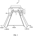
- FIG. 1 shows a schematic diagram of an appearance of an agricultural vehicle S.
- the agricultural vehicle S is a vehicle that travels in a field where a ridge is formed, and is used for farm work (for example, an operation of seeding, spraying agrochemicals, watering, cutting and monitoring) for growing and harvesting crops in the field.
- the agricultural vehicle S automatically travels along the ridge.
- the agricultural vehicle S includes a main body 1, an actuating mechanism 2, wheels 3 (a wheel 3L and a wheel 3R), a laser irradiation device 4, and a control device 5. It should be noted that although two wheels 3 are shown in FIG. 1 , it is assumed that the agricultural vehicle S has four wheels 3 including front wheels and rear wheels. The number of the wheels 3 is arbitrary.
- the main body 1 has a symmetrical shape.
- the main body 1 has the actuating mechanism 2 which has a width in the left-right direction larger than the width of the ridge and moves above the ridge.
- the actuating mechanism 2 is formed by a mechanical component, such as an actuator which operates to cut off crops planted in the ridge or to harvest crops.
- the wheels 3 are provided to both sides of the main body 1 and move in furrows formed between ridges.
- the space between the wheel 3L and the wheel 3R may be adjustable in accordance with the width of the ridge (that is, the space between the furrows).
- the laser irradiation device 4 is a device that radiates a pulsed laser light to the front of the agricultural vehicle S in the traveling direction, and is a Light Detection and Ranging (LiDAR) device, for example.
- the laser irradiation device 4 is fixed to the front face of the main body 1 and radiates laser light in a plurality of directions towards the ridge and the furrow in front of the agricultural vehicle S to detect the laser light reflected by the ridge and the furrow.
- the laser irradiation device 4 switches the direction in which the laser light is radiated at every predetermined period of time, for example.
- the laser irradiation device 4 identifies positions where the laser light has been reflected by the ridge and the furrow, and generates point group data corresponding to the positions where the laser light has been reflected.
- the point group data includes information indicating the relationship between the central direction of a range in which the laser irradiation device 4 radiates the laser light and the position where the laser light has been reflected (e.g., an angle with respect to the central direction), and a distance between the laser irradiation device 4 and the position where the laser light has been reflected.
- An irradiation time of one pulse of the laser light may be any length, and is 1 ns, for example, although the irradiation time affects the required resolution of the position and the distance.
- the control device 5 is a device that controls a traveling direction of the agricultural vehicle S, and is a computer that operates by executing a program, for example.
- the control device 5 analyzes the point group data acquired from the laser irradiation device 4 to identify the direction of the ridge, and controls the orientation of the wheel 3 such that the agricultural vehicle S travels in the identified direction.
- control device 5 the configuration and operations of the control device 5 will be described in detail.
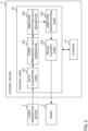
- FIG. 2 shows a configuration of the control device 5.
- the control device 5 includes a storage 51 and a control part 52.
- the storage 51 includes a storage medium, such as a Read Only Memory (ROM), a Random Access Memory (RAM), or a hard disk.
- the storage 51 stores the point group data generated by the laser irradiation device 4.
- the storage 51 stores a program to be executed by the control part 52.
- the control part 52 is a Central Processing Unit (CPU), for example.
- the control part 52 functions as a data acquisition part 521, a three-dimensional data generator 522, a direction identifying data generator 523, a direction identification part 524, and a travel control part 525 by executing a program stored in the storage 51.
- CPU Central Processing Unit
- the data acquisition part 521 acquires the point group data generated by the laser irradiation device 4, from the laser irradiation device 4.
- the data acquisition part 521 notifies the three-dimensional data generator 522 of the acquired point group data.
- the data acquisition part 521 may acquire the point group data associated with time information at a predetermined interval, and may store the point group data that the data acquisition part 521 acquired (hereinafter, sometimes referred to as "acquired point group data") in the storage 51 in association with the time information.
- the three-dimensional data generator 522 generates three-dimensional data indicating the three-dimensional geometry of an area irradiated with the laser light by the laser irradiation device 4, on the basis of the point group data acquired via the data acquisition part 521.
- the three-dimensional data generator 522 generates three-dimensional data on the basis of the point group data acquired by the data acquisition part 521 over a predetermined period of time.
- the predetermined period of time is a time required for the data acquisition part 521 to acquire a sufficient amount of point group data for the direction identification part 524 to identify the direction of the ridge.
- the three-dimensional data generator 522 On the basis of the relationship between the position of the laser light irradiation source and the irradiation position of the laser light in the laser irradiation device 4, the three-dimensional data generator 522 generates three-dimensional data corresponding to a three-dimensional geometry of a region with a horizontal plane as a reference by converting the position of the acquired point group data in a three-dimensional space. Specifically, the three-dimensional data generator 522 generates three-dimensional data in which multiple coordinates of the irradiation position that are the same height in the height direction of the agricultural vehicle S are represented by the same value.
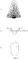
- FIG. 3 is a schematic diagram of the point group data.
- the region surrounded by a dotted line in FIG. 3(a) indicates a region including the acquired point group data acquired by the data acquisition part 521, and is indicated with density corresponding to the distance from the irradiation source of the laser irradiation device 4 to the position irradiated with the laser light, or the reflectance of the laser light.
- the larger the distance from the irradiation source of the laser irradiation device 4 to the position irradiated with the laser light is, the lighter the indicated color is.
- FIG. 3(b) is a schematic diagram showing a state where the three-dimensional data generated by the three-dimensional data generator 522 is recognized from the horizontal direction (e.g., the direction of the traveling surface).
- FIG. 3(c) is a schematic diagram showing a state where the point group data in a height range ( ⁇ h) surrounded by two one-dot chain lines in the three-dimensional data shown in FIG. 3(b) is recognized from above.
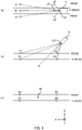
- FIG. 4 is a schematic diagram for explaining an operation in which the three-dimensional data generator 522 generates three-dimensional data.
- FIG. 4(a) shows a state where a part of the point group data is recognized from above the field
- FIG. 4(b) shows a state where a part of the point group data is recognized in the horizontal direction.
- broken lines indicate laser lights
- a circle indicates a piece of point data in the point group data.
- the sign L0 in FIG. 4(a) and FIG.4(b) indicates the position of the laser light irradiation source
- the one-dot chain line indicates a central direction C of a laser light irradiation range.
- the pieces of point data a1, b1, and c1 correspond to positions furthest from the laser irradiation device 4 in the laser light irradiation range
- the pieces of point data a2, b2, and c2 correspond to positions closest to the laser irradiation device 4 in the laser light irradiation range
- the pieces of point data a1, c1, a2, and c2 correspond to positions at which the ridges are irradiated with the laser light
- the pieces of point data b1 and b2 correspond to positions at which the furrow is irradiated with the laser light.
- a position of each piece of point data is represented on the basis of the distance from the irradiation source L0 and the angle from a central irradiation direction C of the laser light, for example.
- the point data a1 is located above the central irradiation direction C, and the point data a2 is located below the central irradiation direction C with the central irradiation direction C of the laser light as a reference, although in fact the pieces of point data a1 and a2 are at the same height.
- the point data b1 and b2 are at the same height, the point data b 1 is located above the central irradiation direction C, and the point data b2 is located below the central irradiation direction C.
- the three-dimensional data generator 522 generates three-dimensional data by converting the coordinates of these pieces of point data into coordinates in the three-dimensional space in which the traveling direction of the agricultural vehicle S is the horizontal direction.
- the three-dimensional data generator 522 To generate three-dimensional data, the three-dimensional data generator 522 first extracts acquired point group data within a predetermined range in the depth direction or the width direction. Subsequently, on the basis of each position of a plurality of pieces of point data included in the acquired point group data that was extracted, the three-dimensional data generator 522 identifies a position that is the center of the plurality of pieces of point data (e.g., the central position M in FIG.4 ). The three-dimensional data generator 522 then generates three-dimensional data by rotating the coordinates of the acquired point group data, with the identified central position M as a rotation center.
- the three-dimensional data generator 522 generates three-dimensional data by calculating coordinates of point data in the three-dimensional space in which the traveling direction of the agricultural vehicle S is the X direction, the left-right direction is the Y direction, and the height direction is the Z direction. It should be noted that the three-dimensional data generator 522 may remove point data that deviates from a predetermined range in the Z direction as noise.
- the three-dimensional data generator 522 converts the coordinates of the point data a1 into A1, and converts the coordinates of the point data a2 into A2 in which the coordinates in the Z direction and Y direction are the same as those of A1 and the coordinate in the X direction is different from that of A1.
- the three-dimensional data generator 522 converts the coordinates of the point data b1 into B 1 in which the coordinate in the X direction is the same as that of A1 and coordinates in the Y direction and the Z direction are different from those of A1.
- the three-dimensional data generator 522 notifies the direction identifying data generator 523 of the generated three-dimensional data in this manner.
- the direction identifying data generator 523 generates direction identifying data including at least a part of the acquired point group data indicating the position of the region including the ridge in the front of the agricultural vehicle S in the traveling direction.
- the direction identifying data generator 523 generates direction identifying data including point group data corresponding to a predetermined range effective for identifying the direction of the ridge, for example.
- the direction identifying data generator 523 generates direction identifying data on the basis of acquired point group data acquired by radiating a pulsed laser light with the laser irradiation device 4, for example.
- the direction identifying data generator 523 generates the direction identifying data used to identify the direction of the ridge by extracting a portion of the point group data corresponding to a predetermined range effective for identifying the direction of the ridge from the point group data included in the three-dimensional data generated on the basis of the acquired point group data, for example.
- the direction identifying data generator 523 notifies the direction identification part 524 of the generated direction identifying data.
- the direction identifying data generator 523 generates the direction identifying data by selecting the point group data corresponding to a predetermined range lower than the upper surface of the ridge from among the point group data included in the three-dimensional data.
- the predetermined range is a range of height between the lowest position in the ridge and the lowest position in the furrow, for example. Since the direction identifying data generator 523 generates the direction identifying data using the point group data in a range lower than the upper surface of the ridge in this manner, the point group data generated by irradiating crops planted on the ridge is not included in the direction identifying data, and so the accuracy of identifying the direction of the ridge is improved. Further, even in a case where the ridge is provided with a tunnel or a supporting pole, the upper portion of the ridge is missing, or irregular reflection occurs above the ridge, the accuracy of identifying the direction of the ridge is improved.
- the direction identifying data generator 523 generates direction identifying data as shown in FIG. 3(c) by selecting point group data within a range defined by an upper surface and a lower surface parallel to a horizontal surface (e.g., a surface bordering the uppermost ends of the four wheels 3) in the agricultural vehicle S, for example.
- the direction identifying data generator 523 may generate a plurality of pieces of direction identifying data including pieces of point group data corresponding to a plurality of predetermined ranges lower than the ridge, with each piece of point group data corresponding to the same height range.
- the direction identifying data generator 523 generates a plurality of pieces of direction identifying data corresponding to a range including a straight line connecting a plurality of wheels 3L on the left side of the agricultural vehicle S and a range including a straight line connecting a plurality of wheels 3R on the right side of the agricultural vehicle S, for example.
- the direction identifying data generator 523 may generate the direction identifying data by calculating the slope of an approximate curve based on a portion of points extracted from a plurality of points included in the point group data, for example. In this case, the direction identifying data generator 523 may calculate inclinations of a plurality of pieces of triangle-shaped polygon data formed by three close points to generate statistical values of a plurality of calculated inclinations as direction identifying data. Further, from among a plurality of templates of the direction identifying data indicating the shape of the ridge, the direction identifying data generator 523 may select the template of the direction identifying data that matches the largest number of point groups.
- the direction identification part 524 identifies the direction of the ridge on the basis of the direction identifying data generated by the direction identifying data generator 523.
- the direction identification part 524 identifies the direction of the ridge by calculating an approximate straight line using a method such as a least-squares method or a robust estimation method on the basis of point group data corresponding to a predetermined height included in the direction identifying data, for example.
- the direction identification part 524 calculates an approximate straight line of the region in the longitudinal direction surrounded by the outline of the region including the point group data, thereby identifying the direction of the region with the same height, for example.
- the direction identification part 524 determines that a region with a height equal to or greater than a predetermined height is a region of the ridge and a region with a height less than the predetermined height is a region of the furrow, among the regions in which the direction is identified.
- the direction identification part 524 identifies the longitudinal directions of the identified ridge and furrow as the direction of the ridge and the direction of the furrow.
- the direction identification part 524 identifies the direction of the ridge on the basis of each of the plurality of pieces of direction identifying data.
- the direction identification part 524 identifies a statistical value (e.g., an average value or a median value) of the direction of the ridge identified on the basis of each of the plurality of pieces of direction identifying data as the direction of the ridge, thereby reducing the influence of measurement error.
- the direction identification part 524 may further identify the distance between the wheel 3 and the ridge on the basis of the direction identifying data.
- the direction identification part 524 identifies the distance between i) the boundary defined by the identified region of the ridge and the identified region of the furrow and ii) the position of the right side or the position of the left side of the wheel 3, as the distance between the wheel 3 and the ridge.
- the direction identification part 524 notifies the travel control part 525 of the identified direction of the ridge or the direction of the furrow and the distance between the wheel 3 and the ridge.
- the travel control part 525 controls the agricultural vehicle S such that the agricultural vehicle S travels along the direction of the ridge identified by the direction identification part 524.
- the travel control part 525 controls the direction and the speed of the wheels 3 of the agricultural vehicle S on the basis of the direction of the ridge.
- the travel control part 525 controls the rotational speed or the orientation of each of the wheel 3L and the wheel 3R such that the agricultural vehicle S travels along the direction of the ridge notified from the direction identification part 524.
- the travel control part 525 may control the rotational speed or the orientation of the wheels 3 of the agricultural vehicle S on the basis of the distance identified by the direction identification part 524.
- the travel control part 525 controls the rotational speed or the orientation of the wheels 3 such that the distance between a wheel 3 and the ridge is within a predetermined range, for example.
- the travel control part 525 detects that the distance between the wheel 3L and the ridge becomes larger than the predetermined range, the travel control part 525 changes the rotational speed of the wheel 3L to be greater than the rotational speed of the wheel 3R, or changes the orientation of the wheels 3 such that the distance between a wheel 3 and the ridge becomes smaller. Since the travel control part 525 operates in this manner, the agricultural vehicle S travels along the direction of the ridge. In addition, when the distance between a wheel 3 and the ridge is out of the predetermined range due to the change in the direction of the ridge, the agricultural vehicle S can quickly change the traveling direction to travel along the direction of the ridge.
- the travel control part 525 stops the agricultural vehicle S.
- the travel control part 525 may switch to traveling based on radio waves received from a GPS satellite when the direction identification part 524 is unable to identify the direction of the ridge.
- the travel control part 525 operating in this manner makes it possible to prevent further collapse of the ridge resulting from the travel of the agricultural vehicle S.
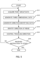
- FIG. 5 is a flowchart showing a flow of a process in the control device 5. The flowchart shown in FIG. 5 starts at the time when the control part 52 is activated.
- the data acquisition part 521 acquires point group data at a predetermined interval (S11).
- the three-dimensional data generator 522 generates three-dimensional data on the basis of the point group data acquired by the data acquisition part 521 (S12), and the direction identifying data generator 523 generates direction identifying data by selecting point group data corresponding to a position lower than the upper surface of the ridge in the three-dimensional data (S13).
- the direction identification part 524 identifies the direction of the ridge by identifying the boundary position between the ridge and the furrow on the basis of the direction identifying data (S14).
- the travel control part 525 controls the traveling direction of the agricultural vehicle S such that the agricultural vehicle S travels in the direction identified by the direction identification part 524 (S15).
- the control part 52 monitors whether or not an instruction to stop the operation has been received (S16), and repeats the process from S11 to S16 until receiving the instruction to stop the operation (NO in S16). When the instruction to stop has been received (YES in S16), the control part 52 ends the operation.
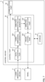
- FIG. 6 shows a configuration of a variation example of the control device 5.
- the control device 5 shown in FIG. 6 is different from the control device 5 shown in FIG. 2 in that the control device 5 further includes an unevenness identification part 526 and a mechanism control part 527, and is the same in other respects.
- the unevenness identification part 526 identifies an unevenness of the furrow between a plurality of ridges on the basis of the acquired point group data acquired by the data acquisition part 521. On the basis of the position in the height direction of the point group data included in the three-dimensional data generated by the three-dimensional data generator 522 on the basis of the acquired point group data, the unevenness identification part 526 identifies the unevenness by identifying the height of each of a plurality of positions on the furrow in the traveling direction, with the lowest position on the furrow as a reference, for example.
- the mechanism control part 527 controls the height of the actuating mechanism 2 which operates above the ridge in the agricultural vehicle S, on the basis of the unevenness identified by the unevenness identification part 526.
- the position of the actuating mechanism 2 in the height direction also varies as the position of the agricultural vehicle S in the height direction varies due to the unevenness of the furrow, the height of the actuating mechanism 2 with respect to the position of the crop may vary. Due to this, if the actuating mechanism 2 has a mechanism for cutting a root of the crop, a furrow having a convex portion would cause the crop to be cut at a position higher than the root of the crop, for example.
- the mechanism control part 527 controls the actuating mechanism 2 such that the position of the actuating mechanism 2 in the height direction is within a fixed range in accordance with the unevenness of the furrow, the height of the actuating mechanism 2 with respect to the position of the crop does not vary.
- the actuating mechanism 2 has a mechanism for cutting the root of the crop, the actuating mechanism 2 can cut the crop at approximately the same position.
- control device 5 shown in FIG. 6 need not include the unevenness identification part 526, and the mechanism control part 527 may control the position of the actuating mechanism 2 in the left-right direction on the basis of the direction of the ridge identified by the direction identification part 524.
- the mechanism control part 527 changes the position of the actuating mechanism 2 used for spraying agrochemicals, in the left-right direction, or changes the position of a mechanism for cutting the root of the crop, in the left-right direction, for example.
- the mechanism control part 527 may change the position of the actuating mechanism 2 in the left-right direction on condition that the traveling direction of the agricultural vehicle S and the direction of the ridge deviate from each other by a threshold or more.
- control device 5 may have a communication function of transmitting and receiving data to and from an electronic device driving the wheel 3, and the travel control part 525 may control the traveling direction of the agricultural vehicle S by transmitting data indicating the traveling direction to the electronic device.
- the control device 5 is a smartphone, a tablet, or a personal computer, for example.
- the travel control part 525 controls the position of the agricultural vehicle S in the left-right direction on the basis of the direction of the ridge identified by the direction identification part 524 , but the travel control part 525 may perform other controls on the basis of the direction of the ridge identified by the direction identification part 524.
- the travel control part 525 controls travel torque of the agricultural vehicle S on the basis of the direction of the ridge, for example. Specifically, the travel control part 525 increases the travel torque when the direction of the ridge or furrow identified by the direction identification part 524 is inclined upward (that is, an upward slope) more than the travel torque when the direction of the ridge or furrow is inclined downward (that is, a downward slope). Since the travel control part 525 operates in this manner, the traveling speed of the agricultural vehicle S is stabilized regardless of the slopes of the field.
- the direction identifying data generator 523 generated direction identifying data including a portion of the point group data included in the three-dimensional data generated by the three-dimensional data generator 522, but the direction identifying data generator 523 may use the acquired point group data acquired by the data acquisition part 521 itself as the direction identifying data.
- the laser irradiation device 4 radiates laser light only over a range with a preset height (e.g., a range lower than the crops planted in the ridge). A process of converting the three-dimensional data into the direction identifying data becomes unnecessary since the laser irradiation device 4 and the direction identifying data generator 523 operate in this manner, making it possible to shorten the time required for the direction identification part 524 to identify the direction of the ridge.
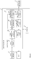
- FIG. 7 shows another example of the control device 5.
- the control device 5 shown in FIG. 7 is different from the control device 5 shown in FIG. 2 in that the control device 5 shown in FIG. 7 further includes a communication part 53, and is the same in other respects.
- the communication part 53 has a wireless communication unit for transmitting and receiving data to and from another agricultural vehicle Sb traveling behind the agricultural vehicle S, for example.
- the communication part 53 transmits acquired point group data acquired from the laser irradiation device 4 to this other agricultural vehicle Sb traveling behind the agricultural vehicle S.
- the agricultural vehicle Sb includes a control part which functions as a three-dimensional data generator 522, a direction identifying data generator 523, a direction identification part 524, and a travel control part 525.
- the agricultural vehicle Sb identifies the traveling direction on the basis of the acquired point group data received from the agricultural vehicle S, and travels in the identified direction.
- the agricultural vehicle S may transmit the three-dimensional data or the direction identifying data to the agricultural vehicle Sb via the communication part 53, and the agricultural vehicle Sb may travel on the basis of the received three-dimensional data or direction identifying data.
- the direction identification part 524 of the agricultural vehicle Sb may identify the traveling direction using the acquired point group data, the three-dimensional data, or the direction identifying data at a timing delayed by a time determined on the basis of the distance between the agricultural vehicle S and the agricultural vehicle Sb, and the speed of the agricultural vehicle Sb, from when the acquired point group data, the three-dimensional data, or the direction identifying data is received from the agricultural vehicle S.
- the agricultural vehicle S transmits the acquired point group data, the three-dimensional data, or the direction identifying data to the agricultural vehicle Sb, thereby allowing the agricultural vehicle Sb to travel along the direction of the ridge even if the laser irradiation device 4 is not included in the agricultural vehicle Sb.
- the direction identification part 524 may identify the direction of the tunnel as the direction of the ridge, for example.
- the direction identification part 524 is unable to identify the direction of the ridge.
- the direction identifying data generator 523 may expand the range of the point group data used as the direction identifying data.
- the laser irradiation device 4 may be provided with multiple light sources, arranged in the height direction of the agricultural vehicle, that radiate the laser light in the horizontal direction, and a point group may be acquired as a result of radiating the laser light in the horizontal direction with these multiple light sources.
- the agricultural vehicle S has the laser irradiation device 4 and the direction of the ridge is identified on the basis of the point group data generated on the basis of the laser light radiated by the laser irradiation device 4 has been described.
- Using the laser light enables the agricultural vehicle S to drive autonomously and to perform farm work regardless of weather and the like, even on rainy days or in poor visibility.
- means for acquiring the point group data by the agricultural vehicle S is not limited to the laser irradiation device 4, and may be means capable of acquiring the shape of the ridge as the point group data.
- the agricultural vehicle S may acquire point group data with a stereo camera (a compound-eye camera) capable of generating distance data indicating a distance to a subject, for example.
- the stereo camera identifies the distance from the camera to the subject on the basis of the distance between two pixels (parallax) corresponding to the position of the same subject in two captured images obtained by photographing the front of the agricultural vehicle S with two cameras, for example.
- the stereo camera inputs data, indicating the distance from the camera to the subject corresponding to each pixel as point group data, into the control device 5.
- the three-dimensional data generator 522 generates three-dimensional data indicating a three-dimensional geometry of a region corresponding to the imaging range of the stereo camera. As just described, even when the agricultural vehicle S has a stereo camera, the direction of the ridge can be identified by a similar process as in a case where the agricultural vehicle S has the laser irradiation device 4.
- the agricultural vehicle S is provided with the laser irradiation device 4 that radiates pulsed laser light to the front in the traveling direction.
- the control device 5 identifies the direction of the ridge in the field where the agricultural vehicle S travels, on the basis of the point group data acquired by the laser irradiation device 4 that radiates the laser light, and controls the agricultural vehicle S such that the agricultural vehicle S travels in the identified direction. Having such a configuration, the agricultural vehicle S can travel on the basis of the direction of the identified ridge, and therefore the agricultural vehicle can travel along the direction of the ridge without frequently moving in the left-right direction when a part of the ridge is collapsed or the ridge is uneven.
- the agricultural vehicle S can change the travel torque in accordance with the slope by detecting a change of the ridge and the furrow in the height direction, the traveling performance can be improved. Further, the agricultural vehicle S can stop when there is a steep downward slope by detecting a change of the ridge and the furrow in the height direction, thereby improving safety.
Landscapes
- Engineering & Computer Science (AREA)
- Physics & Mathematics (AREA)
- Remote Sensing (AREA)
- General Physics & Mathematics (AREA)
- Radar, Positioning & Navigation (AREA)
- Automation & Control Theory (AREA)
- Aviation & Aerospace Engineering (AREA)
- Life Sciences & Earth Sciences (AREA)
- Electromagnetism (AREA)
- Computer Networks & Wireless Communication (AREA)
- Environmental Sciences (AREA)
- Soil Sciences (AREA)
- Mechanical Engineering (AREA)
- Multimedia (AREA)
- Optics & Photonics (AREA)
- Guiding Agricultural Machines (AREA)
- Control Of Position, Course, Altitude, Or Attitude Of Moving Bodies (AREA)
- Length Measuring Devices By Optical Means (AREA)
Abstract
Description
- The present disclosure relates to an agricultural vehicle, a control device, and a program for controlling the agricultural vehicle.
- Conventionally, there is known an agricultural vehicle that detects a position of a ridge in a width direction in a field and travels while controlling a position of the vehicle in a width direction on the basis of the detected position (see, e.g., Patent document 1).
- Patent Document 1:
Japanese Unexamined Patent Application Publication No. 2019-062816 - A conventional agricultural vehicle measures a distance between a ridge and an ultrasonic sensor provided in the agricultural vehicle, and controls a position of the agricultural vehicle in the left-right direction on the basis of the measured distance. Thus, the conventional agricultural vehicle has a problem that the agricultural vehicle frequently moves in the left-right direction when a part of the ridge is collapsed or the ridge is uneven.
- The present disclosure focuses on these points, and an object of the present disclosure is to improve stability when the agricultural vehicle travels along a direction of the ridge.
- A control device according to the first embodiment of the present disclosure is a control device for controlling an agricultural vehicle that travels in a field where a ridge is formed, the control device includes a direction identifying data generator that generates direction identifying data including at least a portion of acquired point group data indicating a position of a region including the ridge in front of the agricultural vehicle in a traveling direction, a direction identification part that identifies a direction of the ridge on the basis of the direction identifying data, and a travel control part that controls the agricultural vehicle such that the agricultural vehicle travels along the direction of the ridge identified by the direction identification part.
- The control device may further include a three-dimensional data generator that generates three-dimensional data indicating a three-dimensional geometry of the region on the basis of the point group data, wherein the direction identifying data generator may generate the direction identifying data by extracting a portion of the point group data corresponding to a predetermined range effective for identifying the direction of the ridge, from among the point group data included in the three-dimensional data.
- The acquired point group data may be data acquired by radiating a pulsed laser light from a laser light irradiation source, and the three-dimensional data generator may generate the three-dimensional data corresponding to the three-dimensional geometry of the region with a horizontal plane as a reference by converting the position of the acquired point group data in three-dimensional space on the basis of the relationship between the position of the laser light irradiation source and the irradiation position of the laser light.
- The direction identifying data generator may generate the direction identifying data by selecting the portion of the point group data corresponding to the predetermined range lower than the upper surface of the ridge, from among the point group data included in the three-dimensional data.
- The control device may further include an unevenness identification part that identifies unevenness in a furrow between a plurality of the ridges on the basis of the acquired point group data, and a mechanism control part that controls a height of an actuating mechanism operating above the ridge with respect to the agricultural vehicle on the basis of the unevenness identified by the unevenness identification part.
- The control device may further include a mechanism control part that controls a position of an actuating mechanism, in the left-right direction, that operates above the ridge with respect to the agricultural vehicle on the basis of the direction of the ridge identified by the direction identification part.
- The direction identifying data generator may generate the direction identifying data by selecting the point group data within a range defined by an upper surface and a lower surface parallel to a horizontal plane of the agricultural vehicle.
- The direction identifying data generator may generate a plurality of pieces of the direction identifying data including the point group data corresponding to a plurality of predetermined ranges lower than the ridge, with each piece of the point group data corresponding to the same height range, and the direction identification part may identify the direction of the ridge on the basis of the plurality of pieces of direction identifying data.
- The direction identification part may identify the direction of the ridge on the basis of a direction of an outline of a region formed by the point group data corresponding to a predetermined height included in the direction identifying data.
- The travel control part may control an orientation and a speed of a wheel of the agricultural vehicle on the basis of the direction of the ridge.
- The direction identification part may further identify a distance between the wheel and the ridge on the basis of the direction identifying data, and the travel control part may control the orientation and the speed of the wheel of the agricultural vehicle on the basis of the distance identified by the direction identification part.
- The travel control part may stop the agricultural vehicle when the direction identification part is unable to identify the direction of the ridge.
- The control device may further include a communication part that transmits the acquired point group data to another agricultural vehicle traveling behind the agricultural vehicle.
- An agricultural vehicle according to the second embodiment of the present disclosure is an agricultural vehicle that travels in a field where a ridge is formed, the agricultural vehicle includes a control device that controls the agricultural vehicle, and a laser irradiation device that transmits acquired point group data acquired by radiating pulsed laser light in front of the agricultural vehicle in a traveling direction, to the control device, wherein the control device includes a direction identifying data generator that generates direction identifying data including at least a portion of the acquired point group data indicating a position of a region including the ridge in front of the agricultural vehicle in a traveling direction, a direction identification part that identifies a direction of the ridge on the basis of the direction identifying data, and a travel control part that controls the agricultural vehicle such that the agricultural vehicle travels along the direction of the ridge identified by the direction identification part.
- A program according to the third embodiment of the present disclosure causes a computer to operate as a direction identifying data generator that generates direction identifying data including at least a portion of acquired point group data indicating a position of a region including a ridge in front of an agricultural vehicle, in a traveling direction, that travels in a field where the ridge is formed, a direction identification part that identifies a direction of the ridge on the basis of the direction identifying data, and a travel control part that controls the agricultural vehicle such that the agricultural vehicle travels along the direction of the ridge identified by the direction identification part.
- According to the present disclosure, stability of the agricultural vehicle when traveling along the direction of the ridge can be improved.
-
-
FIG. 1 is a schematic diagram of an appearance of an agricultural vehicle. -
FIG. 2 shows a configuration of a control device. -
FIG. 3 is a schematic diagram of point group data. -
FIG. 4 is a schematic diagram for explaining an operation in which a three-dimensional data generator generates three-dimensional data. -
FIG. 5 is a flowchart showing a flow of a process in the control device. -
FIG. 6 shows a configuration of a variation example of the control device. -
FIG. 7 shows another example of the control device. -
FIG. 1 shows a schematic diagram of an appearance of an agricultural vehicle S. The agricultural vehicle S is a vehicle that travels in a field where a ridge is formed, and is used for farm work (for example, an operation of seeding, spraying agrochemicals, watering, cutting and monitoring) for growing and harvesting crops in the field. The agricultural vehicle S automatically travels along the ridge. The agricultural vehicle S includes a main body 1, anactuating mechanism 2, wheels 3 (awheel 3L and awheel 3R), alaser irradiation device 4, and acontrol device 5. It should be noted that although twowheels 3 are shown inFIG. 1 , it is assumed that the agricultural vehicle S has fourwheels 3 including front wheels and rear wheels. The number of thewheels 3 is arbitrary. - Although the shape of the main body 1 is arbitrary, the main body 1 shown in
FIG. 1 has a symmetrical shape. The main body 1 has theactuating mechanism 2 which has a width in the left-right direction larger than the width of the ridge and moves above the ridge. Theactuating mechanism 2 is formed by a mechanical component, such as an actuator which operates to cut off crops planted in the ridge or to harvest crops. - The
wheels 3 are provided to both sides of the main body 1 and move in furrows formed between ridges. The space between thewheel 3L and thewheel 3R may be adjustable in accordance with the width of the ridge (that is, the space between the furrows). - The
laser irradiation device 4 is a device that radiates a pulsed laser light to the front of the agricultural vehicle S in the traveling direction, and is a Light Detection and Ranging (LiDAR) device, for example. Thelaser irradiation device 4 is fixed to the front face of the main body 1 and radiates laser light in a plurality of directions towards the ridge and the furrow in front of the agricultural vehicle S to detect the laser light reflected by the ridge and the furrow. Thelaser irradiation device 4 switches the direction in which the laser light is radiated at every predetermined period of time, for example. - The
laser irradiation device 4 identifies positions where the laser light has been reflected by the ridge and the furrow, and generates point group data corresponding to the positions where the laser light has been reflected. The point group data includes information indicating the relationship between the central direction of a range in which thelaser irradiation device 4 radiates the laser light and the position where the laser light has been reflected (e.g., an angle with respect to the central direction), and a distance between thelaser irradiation device 4 and the position where the laser light has been reflected. An irradiation time of one pulse of the laser light may be any length, and is 1 ns, for example, although the irradiation time affects the required resolution of the position and the distance. - The
control device 5 is a device that controls a traveling direction of the agricultural vehicle S, and is a computer that operates by executing a program, for example. Thecontrol device 5 analyzes the point group data acquired from thelaser irradiation device 4 to identify the direction of the ridge, and controls the orientation of thewheel 3 such that the agricultural vehicle S travels in the identified direction. - Hereinafter, the configuration and operations of the
control device 5 will be described in detail. -
FIG. 2 shows a configuration of thecontrol device 5. Thecontrol device 5 includes astorage 51 and acontrol part 52. - The
storage 51 includes a storage medium, such as a Read Only Memory (ROM), a Random Access Memory (RAM), or a hard disk. Thestorage 51 stores the point group data generated by thelaser irradiation device 4. In addition, thestorage 51 stores a program to be executed by thecontrol part 52. - The
control part 52 is a Central Processing Unit (CPU), for example. Thecontrol part 52 functions as adata acquisition part 521, a three-dimensional data generator 522, a direction identifyingdata generator 523, adirection identification part 524, and atravel control part 525 by executing a program stored in thestorage 51. - The
data acquisition part 521 acquires the point group data generated by thelaser irradiation device 4, from thelaser irradiation device 4. Thedata acquisition part 521 notifies the three-dimensional data generator 522 of the acquired point group data. Thedata acquisition part 521 may acquire the point group data associated with time information at a predetermined interval, and may store the point group data that thedata acquisition part 521 acquired (hereinafter, sometimes referred to as "acquired point group data") in thestorage 51 in association with the time information. - The three-
dimensional data generator 522 generates three-dimensional data indicating the three-dimensional geometry of an area irradiated with the laser light by thelaser irradiation device 4, on the basis of the point group data acquired via thedata acquisition part 521. The three-dimensional data generator 522 generates three-dimensional data on the basis of the point group data acquired by thedata acquisition part 521 over a predetermined period of time. The predetermined period of time is a time required for thedata acquisition part 521 to acquire a sufficient amount of point group data for thedirection identification part 524 to identify the direction of the ridge. - On the basis of the relationship between the position of the laser light irradiation source and the irradiation position of the laser light in the
laser irradiation device 4, the three-dimensional data generator 522 generates three-dimensional data corresponding to a three-dimensional geometry of a region with a horizontal plane as a reference by converting the position of the acquired point group data in a three-dimensional space. Specifically, the three-dimensional data generator 522 generates three-dimensional data in which multiple coordinates of the irradiation position that are the same height in the height direction of the agricultural vehicle S are represented by the same value. -
FIG. 3 is a schematic diagram of the point group data. The region surrounded by a dotted line inFIG. 3(a) indicates a region including the acquired point group data acquired by thedata acquisition part 521, and is indicated with density corresponding to the distance from the irradiation source of thelaser irradiation device 4 to the position irradiated with the laser light, or the reflectance of the laser light. InFIG. 3 , the larger the distance from the irradiation source of thelaser irradiation device 4 to the position irradiated with the laser light is, the lighter the indicated color is. -
FIG. 3(b) is a schematic diagram showing a state where the three-dimensional data generated by the three-dimensional data generator 522 is recognized from the horizontal direction (e.g., the direction of the traveling surface).FIG. 3(c) is a schematic diagram showing a state where the point group data in a height range (Δh) surrounded by two one-dot chain lines in the three-dimensional data shown inFIG. 3(b) is recognized from above. -
FIG. 4 is a schematic diagram for explaining an operation in which the three-dimensional data generator 522 generates three-dimensional data.FIG. 4(a) shows a state where a part of the point group data is recognized from above the field, andFIG. 4(b) shows a state where a part of the point group data is recognized in the horizontal direction. In the figures, broken lines indicate laser lights, and a circle indicates a piece of point data in the point group data. The sign L0 inFIG. 4(a) and FIG.4(b) indicates the position of the laser light irradiation source, and the one-dot chain line indicates a central direction C of a laser light irradiation range. - The pieces of point data a1, b1, and c1 correspond to positions furthest from the
laser irradiation device 4 in the laser light irradiation range, and the pieces of point data a2, b2, and c2 correspond to positions closest to thelaser irradiation device 4 in the laser light irradiation range. The pieces of point data a1, c1, a2, and c2 correspond to positions at which the ridges are irradiated with the laser light, and the pieces of point data b1 and b2 correspond to positions at which the furrow is irradiated with the laser light. In the acquired point group data, a position of each piece of point data is represented on the basis of the distance from the irradiation source L0 and the angle from a central irradiation direction C of the laser light, for example. - Since the
laser irradiation device 4 radiates the laser light in an inclined direction, the point data a1 is located above the central irradiation direction C, and the point data a2 is located below the central irradiation direction C with the central irradiation direction C of the laser light as a reference, although in fact the pieces of point data a1 and a2 are at the same height. Similarly, although in fact the pieces of point data b1 and b2 are at the same height, the point data b 1 is located above the central irradiation direction C, and the point data b2 is located below the central irradiation direction C. Accordingly, the three-dimensional data generator 522 generates three-dimensional data by converting the coordinates of these pieces of point data into coordinates in the three-dimensional space in which the traveling direction of the agricultural vehicle S is the horizontal direction. - To generate three-dimensional data, the three-
dimensional data generator 522 first extracts acquired point group data within a predetermined range in the depth direction or the width direction. Subsequently, on the basis of each position of a plurality of pieces of point data included in the acquired point group data that was extracted, the three-dimensional data generator 522 identifies a position that is the center of the plurality of pieces of point data (e.g., the central position M inFIG.4 ). The three-dimensional data generator 522 then generates three-dimensional data by rotating the coordinates of the acquired point group data, with the identified central position M as a rotation center. That is, the three-dimensional data generator 522 generates three-dimensional data by calculating coordinates of point data in the three-dimensional space in which the traveling direction of the agricultural vehicle S is the X direction, the left-right direction is the Y direction, and the height direction is the Z direction. It should be noted that the three-dimensional data generator 522 may remove point data that deviates from a predetermined range in the Z direction as noise. - In an example shown in
FIG. 4(c) , the three-dimensional data generator 522 converts the coordinates of the point data a1 into A1, and converts the coordinates of the point data a2 into A2 in which the coordinates in the Z direction and Y direction are the same as those of A1 and the coordinate in the X direction is different from that of A1. The three-dimensional data generator 522 converts the coordinates of the point data b1 into B 1 in which the coordinate in the X direction is the same as that of A1 and coordinates in the Y direction and the Z direction are different from those of A1. The three-dimensional data generator 522 notifies the direction identifyingdata generator 523 of the generated three-dimensional data in this manner. - The direction identifying
data generator 523 generates direction identifying data including at least a part of the acquired point group data indicating the position of the region including the ridge in the front of the agricultural vehicle S in the traveling direction. The direction identifyingdata generator 523 generates direction identifying data including point group data corresponding to a predetermined range effective for identifying the direction of the ridge, for example. The direction identifyingdata generator 523 generates direction identifying data on the basis of acquired point group data acquired by radiating a pulsed laser light with thelaser irradiation device 4, for example. The direction identifyingdata generator 523 generates the direction identifying data used to identify the direction of the ridge by extracting a portion of the point group data corresponding to a predetermined range effective for identifying the direction of the ridge from the point group data included in the three-dimensional data generated on the basis of the acquired point group data, for example. The direction identifyingdata generator 523 notifies thedirection identification part 524 of the generated direction identifying data. - As an example, the direction identifying
data generator 523 generates the direction identifying data by selecting the point group data corresponding to a predetermined range lower than the upper surface of the ridge from among the point group data included in the three-dimensional data. The predetermined range is a range of height between the lowest position in the ridge and the lowest position in the furrow, for example. Since the direction identifyingdata generator 523 generates the direction identifying data using the point group data in a range lower than the upper surface of the ridge in this manner, the point group data generated by irradiating crops planted on the ridge is not included in the direction identifying data, and so the accuracy of identifying the direction of the ridge is improved. Further, even in a case where the ridge is provided with a tunnel or a supporting pole, the upper portion of the ridge is missing, or irregular reflection occurs above the ridge, the accuracy of identifying the direction of the ridge is improved. - The direction identifying
data generator 523 generates direction identifying data as shown inFIG. 3(c) by selecting point group data within a range defined by an upper surface and a lower surface parallel to a horizontal surface (e.g., a surface bordering the uppermost ends of the four wheels 3) in the agricultural vehicle S, for example. The direction identifyingdata generator 523 may generate a plurality of pieces of direction identifying data including pieces of point group data corresponding to a plurality of predetermined ranges lower than the ridge, with each piece of point group data corresponding to the same height range. The direction identifyingdata generator 523 generates a plurality of pieces of direction identifying data corresponding to a range including a straight line connecting a plurality ofwheels 3L on the left side of the agricultural vehicle S and a range including a straight line connecting a plurality ofwheels 3R on the right side of the agricultural vehicle S, for example. - It should be noted that a method by which the direction identifying
data generator 523 generates the direction identifying data is arbitrary. The direction identifyingdata generator 523 may generate the direction identifying data by calculating the slope of an approximate curve based on a portion of points extracted from a plurality of points included in the point group data, for example. In this case, the direction identifyingdata generator 523 may calculate inclinations of a plurality of pieces of triangle-shaped polygon data formed by three close points to generate statistical values of a plurality of calculated inclinations as direction identifying data. Further, from among a plurality of templates of the direction identifying data indicating the shape of the ridge, the direction identifyingdata generator 523 may select the template of the direction identifying data that matches the largest number of point groups. - The
direction identification part 524 identifies the direction of the ridge on the basis of the direction identifying data generated by the direction identifyingdata generator 523. Thedirection identification part 524 identifies the direction of the ridge by calculating an approximate straight line using a method such as a least-squares method or a robust estimation method on the basis of point group data corresponding to a predetermined height included in the direction identifying data, for example. Thedirection identification part 524 calculates an approximate straight line of the region in the longitudinal direction surrounded by the outline of the region including the point group data, thereby identifying the direction of the region with the same height, for example. - The
direction identification part 524 determines that a region with a height equal to or greater than a predetermined height is a region of the ridge and a region with a height less than the predetermined height is a region of the furrow, among the regions in which the direction is identified. Thedirection identification part 524 identifies the longitudinal directions of the identified ridge and furrow as the direction of the ridge and the direction of the furrow. - When the direction identifying
data generator 523 generates a plurality of pieces of direction identifying data, thedirection identification part 524 identifies the direction of the ridge on the basis of each of the plurality of pieces of direction identifying data. Thedirection identification part 524 identifies a statistical value (e.g., an average value or a median value) of the direction of the ridge identified on the basis of each of the plurality of pieces of direction identifying data as the direction of the ridge, thereby reducing the influence of measurement error. - The
direction identification part 524 may further identify the distance between thewheel 3 and the ridge on the basis of the direction identifying data. Thedirection identification part 524 identifies the distance between i) the boundary defined by the identified region of the ridge and the identified region of the furrow and ii) the position of the right side or the position of the left side of thewheel 3, as the distance between thewheel 3 and the ridge. Thedirection identification part 524 notifies thetravel control part 525 of the identified direction of the ridge or the direction of the furrow and the distance between thewheel 3 and the ridge. - The
travel control part 525 controls the agricultural vehicle S such that the agricultural vehicle S travels along the direction of the ridge identified by thedirection identification part 524. Thetravel control part 525 controls the direction and the speed of thewheels 3 of the agricultural vehicle S on the basis of the direction of the ridge. Thetravel control part 525 controls the rotational speed or the orientation of each of thewheel 3L and thewheel 3R such that the agricultural vehicle S travels along the direction of the ridge notified from thedirection identification part 524. - Further, the
travel control part 525 may control the rotational speed or the orientation of thewheels 3 of the agricultural vehicle S on the basis of the distance identified by thedirection identification part 524. Thetravel control part 525 controls the rotational speed or the orientation of thewheels 3 such that the distance between awheel 3 and the ridge is within a predetermined range, for example. - Specifically, when the
travel control part 525 detects that the distance between thewheel 3L and the ridge becomes larger than the predetermined range, thetravel control part 525 changes the rotational speed of thewheel 3L to be greater than the rotational speed of thewheel 3R, or changes the orientation of thewheels 3 such that the distance between awheel 3 and the ridge becomes smaller. Since thetravel control part 525 operates in this manner, the agricultural vehicle S travels along the direction of the ridge. In addition, when the distance between awheel 3 and the ridge is out of the predetermined range due to the change in the direction of the ridge, the agricultural vehicle S can quickly change the traveling direction to travel along the direction of the ridge. - It should be noted that when the
direction identification part 524 is unable to identify the direction of the ridge, thetravel control part 525 stops the agricultural vehicle S. Thetravel control part 525 may switch to traveling based on radio waves received from a GPS satellite when thedirection identification part 524 is unable to identify the direction of the ridge. In a state where thedirection identification part 524 is unable to identify the direction of the ridge, e.g., when the ridge is collapsed, thetravel control part 525 operating in this manner makes it possible to prevent further collapse of the ridge resulting from the travel of the agricultural vehicle S. -
FIG. 5 is a flowchart showing a flow of a process in thecontrol device 5. The flowchart shown inFIG. 5 starts at the time when thecontrol part 52 is activated. - The
data acquisition part 521 acquires point group data at a predetermined interval (S11). The three-dimensional data generator 522 generates three-dimensional data on the basis of the point group data acquired by the data acquisition part 521 (S12), and the direction identifyingdata generator 523 generates direction identifying data by selecting point group data corresponding to a position lower than the upper surface of the ridge in the three-dimensional data (S13). - The
direction identification part 524 identifies the direction of the ridge by identifying the boundary position between the ridge and the furrow on the basis of the direction identifying data (S14). Thetravel control part 525 controls the traveling direction of the agricultural vehicle S such that the agricultural vehicle S travels in the direction identified by the direction identification part 524 (S15). - The
control part 52 monitors whether or not an instruction to stop the operation has been received (S16), and repeats the process from S11 to S16 until receiving the instruction to stop the operation (NO in S16). When the instruction to stop has been received (YES in S16), thecontrol part 52 ends the operation. -
FIG. 6 shows a configuration of a variation example of thecontrol device 5. Thecontrol device 5 shown inFIG. 6 is different from thecontrol device 5 shown inFIG. 2 in that thecontrol device 5 further includes anunevenness identification part 526 and amechanism control part 527, and is the same in other respects. - The
unevenness identification part 526 identifies an unevenness of the furrow between a plurality of ridges on the basis of the acquired point group data acquired by thedata acquisition part 521. On the basis of the position in the height direction of the point group data included in the three-dimensional data generated by the three-dimensional data generator 522 on the basis of the acquired point group data, theunevenness identification part 526 identifies the unevenness by identifying the height of each of a plurality of positions on the furrow in the traveling direction, with the lowest position on the furrow as a reference, for example. - The
mechanism control part 527 controls the height of theactuating mechanism 2 which operates above the ridge in the agricultural vehicle S, on the basis of the unevenness identified by theunevenness identification part 526. When the position of theactuating mechanism 2 in the height direction also varies as the position of the agricultural vehicle S in the height direction varies due to the unevenness of the furrow, the height of theactuating mechanism 2 with respect to the position of the crop may vary. Due to this, if theactuating mechanism 2 has a mechanism for cutting a root of the crop, a furrow having a convex portion would cause the crop to be cut at a position higher than the root of the crop, for example. - On the other hand, since the
mechanism control part 527 controls theactuating mechanism 2 such that the position of theactuating mechanism 2 in the height direction is within a fixed range in accordance with the unevenness of the furrow, the height of theactuating mechanism 2 with respect to the position of the crop does not vary. As a result, when theactuating mechanism 2 has a mechanism for cutting the root of the crop, theactuating mechanism 2 can cut the crop at approximately the same position. - It should be noted that the
control device 5 shown inFIG. 6 need not include theunevenness identification part 526, and themechanism control part 527 may control the position of theactuating mechanism 2 in the left-right direction on the basis of the direction of the ridge identified by thedirection identification part 524. When the direction of the ridge varies by a threshold or more, themechanism control part 527 changes the position of theactuating mechanism 2 used for spraying agrochemicals, in the left-right direction, or changes the position of a mechanism for cutting the root of the crop, in the left-right direction, for example. Themechanism control part 527 may change the position of theactuating mechanism 2 in the left-right direction on condition that the traveling direction of the agricultural vehicle S and the direction of the ridge deviate from each other by a threshold or more. - Although a case where the
control device 5 is included in the agricultural vehicle S has been described in the above description, thecontrol device 5 need not be included in the agricultural vehicle S. Thecontrol device 5 may have a communication function of transmitting and receiving data to and from an electronic device driving thewheel 3, and thetravel control part 525 may control the traveling direction of the agricultural vehicle S by transmitting data indicating the traveling direction to the electronic device. In this case, thecontrol device 5 is a smartphone, a tablet, or a personal computer, for example. - In the above description, a case where the
travel control part 525 controls the position of the agricultural vehicle S in the left-right direction on the basis of the direction of the ridge identified by thedirection identification part 524 has been described, but thetravel control part 525 may perform other controls on the basis of the direction of the ridge identified by thedirection identification part 524. Thetravel control part 525 controls travel torque of the agricultural vehicle S on the basis of the direction of the ridge, for example. Specifically, thetravel control part 525 increases the travel torque when the direction of the ridge or furrow identified by thedirection identification part 524 is inclined upward (that is, an upward slope) more than the travel torque when the direction of the ridge or furrow is inclined downward (that is, a downward slope). Since thetravel control part 525 operates in this manner, the traveling speed of the agricultural vehicle S is stabilized regardless of the slopes of the field. - In the above description, the direction identifying
data generator 523 generated direction identifying data including a portion of the point group data included in the three-dimensional data generated by the three-dimensional data generator 522, but the direction identifyingdata generator 523 may use the acquired point group data acquired by thedata acquisition part 521 itself as the direction identifying data. In this case, thelaser irradiation device 4 radiates laser light only over a range with a preset height (e.g., a range lower than the crops planted in the ridge). A process of converting the three-dimensional data into the direction identifying data becomes unnecessary since thelaser irradiation device 4 and the direction identifyingdata generator 523 operate in this manner, making it possible to shorten the time required for thedirection identification part 524 to identify the direction of the ridge. -
FIG. 7 shows another example of thecontrol device 5. Thecontrol device 5 shown inFIG. 7 is different from thecontrol device 5 shown inFIG. 2 in that thecontrol device 5 shown inFIG. 7 further includes acommunication part 53, and is the same in other respects. - The
communication part 53 has a wireless communication unit for transmitting and receiving data to and from another agricultural vehicle Sb traveling behind the agricultural vehicle S, for example. Thecommunication part 53 transmits acquired point group data acquired from thelaser irradiation device 4 to this other agricultural vehicle Sb traveling behind the agricultural vehicle S. - The agricultural vehicle Sb includes a control part which functions as a three-
dimensional data generator 522, a direction identifyingdata generator 523, adirection identification part 524, and atravel control part 525. The agricultural vehicle Sb identifies the traveling direction on the basis of the acquired point group data received from the agricultural vehicle S, and travels in the identified direction. The agricultural vehicle S may transmit the three-dimensional data or the direction identifying data to the agricultural vehicle Sb via thecommunication part 53, and the agricultural vehicle Sb may travel on the basis of the received three-dimensional data or direction identifying data. - The
direction identification part 524 of the agricultural vehicle Sb may identify the traveling direction using the acquired point group data, the three-dimensional data, or the direction identifying data at a timing delayed by a time determined on the basis of the distance between the agricultural vehicle S and the agricultural vehicle Sb, and the speed of the agricultural vehicle Sb, from when the acquired point group data, the three-dimensional data, or the direction identifying data is received from the agricultural vehicle S. Thus, the agricultural vehicle S transmits the acquired point group data, the three-dimensional data, or the direction identifying data to the agricultural vehicle Sb, thereby allowing the agricultural vehicle Sb to travel along the direction of the ridge even if thelaser irradiation device 4 is not included in the agricultural vehicle Sb. - <Sixth variation example>
- In the above description, it is assumed that only the crops are planted in the ridge, but an object other than the crops may be put in the ridge. When a tunnel covering the crops is formed, the
direction identification part 524 may identify the direction of the tunnel as the direction of the ridge, for example. - In such a case, it is assumed that the
direction identification part 524 is unable to identify the direction of the ridge. When thedirection identification part 524 is unable to identify the direction of the ridge, the direction identifyingdata generator 523 may expand the range of the point group data used as the direction identifying data. - In the above description, a case where a
laser irradiation device 4 changes the irradiation direction of the laser light has been described, but thelaser irradiation device 4 may be provided with multiple light sources, arranged in the height direction of the agricultural vehicle, that radiate the laser light in the horizontal direction, and a point group may be acquired as a result of radiating the laser light in the horizontal direction with these multiple light sources. - In the above description, a case where the agricultural vehicle S has the
laser irradiation device 4 and the direction of the ridge is identified on the basis of the point group data generated on the basis of the laser light radiated by thelaser irradiation device 4 has been described. Using the laser light enables the agricultural vehicle S to drive autonomously and to perform farm work regardless of weather and the like, even on rainy days or in poor visibility. However, means for acquiring the point group data by the agricultural vehicle S is not limited to thelaser irradiation device 4, and may be means capable of acquiring the shape of the ridge as the point group data. The agricultural vehicle S may acquire point group data with a stereo camera (a compound-eye camera) capable of generating distance data indicating a distance to a subject, for example. - When the agricultural vehicle S has a stereo camera, the stereo camera identifies the distance from the camera to the subject on the basis of the distance between two pixels (parallax) corresponding to the position of the same subject in two captured images obtained by photographing the front of the agricultural vehicle S with two cameras, for example. The stereo camera inputs data, indicating the distance from the camera to the subject corresponding to each pixel as point group data, into the
control device 5. The three-dimensional data generator 522 generates three-dimensional data indicating a three-dimensional geometry of a region corresponding to the imaging range of the stereo camera. As just described, even when the agricultural vehicle S has a stereo camera, the direction of the ridge can be identified by a similar process as in a case where the agricultural vehicle S has thelaser irradiation device 4. - As described above, the agricultural vehicle S is provided with the
laser irradiation device 4 that radiates pulsed laser light to the front in the traveling direction. Thecontrol device 5 identifies the direction of the ridge in the field where the agricultural vehicle S travels, on the basis of the point group data acquired by thelaser irradiation device 4 that radiates the laser light, and controls the agricultural vehicle S such that the agricultural vehicle S travels in the identified direction. Having such a configuration, the agricultural vehicle S can travel on the basis of the direction of the identified ridge, and therefore the agricultural vehicle can travel along the direction of the ridge without frequently moving in the left-right direction when a part of the ridge is collapsed or the ridge is uneven. - Further, since the agricultural vehicle S can change the travel torque in accordance with the slope by detecting a change of the ridge and the furrow in the height direction, the traveling performance can be improved. Further, the agricultural vehicle S can stop when there is a steep downward slope by detecting a change of the ridge and the furrow in the height direction, thereby improving safety.
- The present disclosure is explained on the basis of the exemplary embodiments. The technical scope of the present disclosure is not limited to the scope explained in the above embodiments and it is possible to make various changes and modifications within the scope of the disclosure. For example, all or part of the apparatus can be configured to be functionally or physically distributed and integrated in arbitrary units. Further, new exemplary embodiments generated by arbitrary combinations of them are included in the exemplary embodiments of the present disclosure. The effect of the new embodiment caused by the combination has the effect of the original embodiment together.
-
- 1 main body
- 2 actuating mechanism
- 3 wheel
- 4 laser irradiation device
- 5 control device
- 51 storage
- 52 control part
- 521 data acquisition part
- 522 three-dimensional data generator
- 523 direction identifying data generator
- 524 direction identification part
- 525 travel control part
- 526 unevenness identification part
- 527 mechanism control part
Claims (15)
- A control device for controlling an agricultural vehicle that travels in a field where a ridge is formed, the control device comprising:a direction identifying data generator that generates direction identifying data including at least a portion of acquired point group data indicating a position of a region including the ridge in front of the agricultural vehicle in a traveling direction;a direction identification part that identifies a direction of the ridge on the basis of the direction identifying data; anda travel control part that controls the agricultural vehicle such that the agricultural vehicle travels along the direction of the ridge identified by the direction identification part.
- The control device according to claim 1, further comprising a three-dimensional data generator that generates three-dimensional data indicating a three-dimensional geometry of the region on the basis of the point group data, wherein
the direction identifying data generator generates the direction identifying data by extracting a portion of the point group data corresponding to a predetermined range effective for identifying the direction of the ridge, from among the point group data included in the three-dimensional data. - The control device according to claim 2, whereinthe acquired point group data is data acquired by radiating a pulsed laser light from a laser light irradiation source, andthe three-dimensional data generator generates the three-dimensional data corresponding to the three-dimensional geometry of the region with a horizontal plane as a reference by converting the position of the acquired point group data in three-dimensional space on the basis of the relationship between the position of the laser light irradiation source and the irradiation position of the laser light.
- The control device according to claim 2 or 3, wherein
the direction identifying data generator generates the direction identifying data by selecting the portion of the point group data corresponding to the predetermined range lower than the upper surface of the ridge, from among the point group data included in the three-dimensional data. - The control device according to any one of claims 1 to 4, further comprising:an unevenness identification part that identifies unevenness in a furrow between a plurality of the ridges on the basis of the acquired point group data; anda mechanism control part that controls a height of an actuating mechanism operating above the ridge with respect to the agricultural vehicle on the basis of the unevenness identified by the unevenness identification part.
- The control device according to any one of claims 1 to 4, further comprising:
a mechanism control part that controls a position of an actuating mechanism, in the left-right direction, that operates above the ridge with respect to the agricultural vehicle on the basis of the direction of the ridge identified by the direction identification part. - The control device according to any one of claims 1 to 6, wherein
the direction identifying data generator generates the direction identifying data by selecting the point group data within a range defined by an upper surface and a lower surface parallel to a horizontal plane of the agricultural vehicle. - The control device according to any one of claims 1 to 7, whereinthe direction identifying data generator generates a plurality of pieces of the direction identifying data including the point group data corresponding to a plurality of predetermined ranges lower than the ridge, with each piece of the point group data corresponding to the same height range, andthe direction identification part identifies the direction of the ridge on the basis of the plurality of pieces of direction identifying data.
- The control device according to any one of claims 1 to 8, wherein
the direction identification part identifies the direction of the ridge on the basis of a direction of an outline of a region formed by the point group data corresponding to a predetermined height included in the direction identifying data. - The control device according to any one of claims 1 to 9, wherein
the travel control part controls an orientation and a speed of a wheel of the agricultural vehicle on the basis of the direction of the ridge. - The control device according to claim 10, whereinthe direction identification part further identifies a distance between the wheel and the ridge on the basis of the direction identifying data, andthe travel control part controls the orientation and the speed of the wheel of the agricultural vehicle on the basis of the distance identified by the direction identification part.
- The control device according to any one of claims 1 to 11, wherein
the travel control part stops the agricultural vehicle when the direction identification part is unable to identify the direction of the ridge. - The control device according to any one of claims 1 to 12, further comprising:
a communication part that transmits the acquired point group data to another agricultural vehicle traveling behind the agricultural vehicle. - An agricultural vehicle that travels in a field where a ridge is formed, the agricultural vehicle comprising:a control device that controls the agricultural vehicle; anda laser irradiation device that transmits acquired point group data acquired by radiating pulsed laser light in front of the agricultural vehicle in a traveling direction, to the control device, whereinthe control device includes:a direction identifying data generator that generates direction identifying data including at least a portion of the acquired point group data indicating a position of a region including the ridge in front of the agricultural vehicle in a traveling direction;a direction identification part that identifies a direction of the ridge on the basis of the direction identifying data; anda travel control part that controls the agricultural vehicle such that the agricultural vehicle travels along the direction of the ridge identified by the direction identification part.
- A program for causing a computer to operate as:a direction identifying data generator that generates direction identifying data including at least a portion of acquired point group data indicating a position of a region including a ridge in front of an agricultural vehicle, in a traveling direction, that travels in a field where the ridge is formed;a direction identification part that identifies a direction of the ridge on the basis of the direction identifying data; anda travel control part that controls the agricultural vehicle such that the agricultural vehicle travels along the direction of the ridge identified by the direction identification part.
Applications Claiming Priority (2)
| Application Number | Priority Date | Filing Date | Title |
|---|---|---|---|
| JP2020056603A JP6700500B1 (en) | 2020-03-26 | 2020-03-26 | Agricultural work vehicle, control device and program |
| PCT/JP2021/003714 WO2021192624A1 (en) | 2020-03-26 | 2021-02-02 | Agricultural traveling vehicle, control device, and program |
Publications (2)
| Publication Number | Publication Date |
|---|---|
| EP4130659A1 true EP4130659A1 (en) | 2023-02-08 |
| EP4130659A4 EP4130659A4 (en) | 2023-09-20 |
Family
ID=70776065
Family Applications (1)
| Application Number | Title | Priority Date | Filing Date |
|---|---|---|---|
| EP21776910.8A Pending EP4130659A4 (en) | 2020-03-26 | 2021-02-02 | Agricultural traveling vehicle, control device, and program |
Country Status (5)
| Country | Link |
|---|---|
| US (1) | US20230004162A1 (en) |
| EP (1) | EP4130659A4 (en) |
| JP (2) | JP6700500B1 (en) |
| CN (1) | CN115038932A (en) |
| WO (1) | WO2021192624A1 (en) |
Families Citing this family (1)
| Publication number | Priority date | Publication date | Assignee | Title |
|---|---|---|---|---|
| JP2022029732A (en) * | 2020-08-05 | 2022-02-18 | ヤンマーホールディングス株式会社 | Autonomous travel system of farm work vehicle |
Family Cites Families (8)
| Publication number | Priority date | Publication date | Assignee | Title |
|---|---|---|---|---|
| DE19726917A1 (en) * | 1997-06-25 | 1999-01-07 | Claas Selbstfahr Erntemasch | Device on agricultural machinery for contactless scanning of contours extending over the ground |
| JP2006101816A (en) * | 2004-10-08 | 2006-04-20 | Univ Of Tokyo | Method and apparatus for controlling steering |
| JP4873686B2 (en) * | 2006-01-11 | 2012-02-08 | 株式会社前川製作所 | Agricultural material for agricultural work support equipment, farmland using the agricultural material, and method for recognizing the direction of travel of the agricultural work support equipment in the farmland |
| JP2016012348A (en) * | 2014-06-04 | 2016-01-21 | 株式会社リコー | Information processing device, robot and program |
| JP6418604B2 (en) * | 2015-04-30 | 2018-11-07 | 国立大学法人 鹿児島大学 | Working machine and control method thereof |
| JP6458258B1 (en) * | 2017-09-29 | 2019-01-30 | 株式会社 日本計器鹿児島製作所 | Traveling position recognition system, agricultural traveling vehicle, and unmanned automated traveling vehicle |
| JP2019135963A (en) * | 2018-02-09 | 2019-08-22 | 井関農機株式会社 | Work vehicle |
| KR102262845B1 (en) * | 2018-09-12 | 2021-06-09 | 한국로봇융합연구원 | Apparatus for controlling movement of mobile robot and thereof method |
-
2020
- 2020-03-26 JP JP2020056603A patent/JP6700500B1/en active Active
- 2020-04-30 JP JP2020080097A patent/JP7252636B2/en active Active
-
2021
- 2021-02-02 CN CN202180007821.6A patent/CN115038932A/en active Pending
- 2021-02-02 WO PCT/JP2021/003714 patent/WO2021192624A1/en unknown
- 2021-02-02 EP EP21776910.8A patent/EP4130659A4/en active Pending
-
2022
- 2022-09-08 US US17/940,850 patent/US20230004162A1/en active Pending
Also Published As
| Publication number | Publication date |
|---|---|
| JP2021153567A (en) | 2021-10-07 |
| WO2021192624A1 (en) | 2021-09-30 |
| US20230004162A1 (en) | 2023-01-05 |
| JP2021153466A (en) | 2021-10-07 |
| JP7252636B2 (en) | 2023-04-05 |
| CN115038932A (en) | 2022-09-09 |
| EP4130659A4 (en) | 2023-09-20 |
| JP6700500B1 (en) | 2020-05-27 |
Similar Documents
| Publication | Publication Date | Title |
|---|---|---|
| EP3400798B1 (en) | An agricultural system | |
| KR102585219B1 (en) | Device and method to control speed of vehicle | |
| US11175170B2 (en) | Estimating yield of agricultural crops | |
| CN110243372B (en) | Intelligent agricultural machinery navigation system and method based on machine vision | |
| CN104718874B (en) | Yield measurement and base cutter height control system for a harvester | |
| US20200104613A1 (en) | Vacant parking space detection apparatus and vacant parking space detection method | |
| RU2215389C2 (en) | Apparatus and method for non-contact identification of tillage boundaries or related setting values | |
| US20170357267A1 (en) | Autonomous work vehicle obstacle detection system | |
| EP2536264B1 (en) | Method for directing an unloading apparatus of a harvesting machine to a container | |
| US20100063681A1 (en) | Method and arrangement for the steering of a vehicle | |
| US20230004162A1 (en) | Agricultural vehicle, control device, and control method | |
| JP2019152924A (en) | Self-position identification system, vehicle, and processing device | |
| US20220101554A1 (en) | Extracting Feature Values from Point Clouds to Generate Plant Treatments | |
| KR20210048552A (en) | Road detection method for vehicles equipped with LIDAR sensor | |
| WO2020218464A1 (en) | Harvester, obstacle determination program, recording medium on which obstacle determination program is recorded, obstacle determination method, agricultural work machine, control program, recording medium on which control program is recorded, and control method | |
| JP7452069B2 (en) | Road gradient estimation device, road gradient estimation system, and road gradient estimation method | |
| US20220100996A1 (en) | Ground Plane Compensation in Identifying and Treating Plants | |
| KR101801041B1 (en) | Vehicle where shadow region of laser distance sensor is eliminated | |
| JP2022009231A (en) | Determination device, determination method, and determination program | |
| KR20230115976A (en) | Work vehicle, crop state detection system, crop state detection method, crop state detection program, and recording medium on which the crop state detection program is recorded | |
| US20230403964A1 (en) | Method for Estimating a Course of Plant Rows | |
| WO2023120182A1 (en) | Agricultural machine | |
| JP2019139313A (en) | Rank traveling control device, rank traveling control system, and rank traveling control method | |
| KR102334167B1 (en) | Apparatus and method for improving distance resolution using 3D camera based on Time of Flight | |
| US20240077586A1 (en) | Method for generating intensity information having extended expression range by reflecting geometric characteristic of object, and lidar apparatus performing same method |
Legal Events
| Date | Code | Title | Description |
|---|---|---|---|
| STAA | Information on the status of an ep patent application or granted ep patent |
Free format text: STATUS: THE INTERNATIONAL PUBLICATION HAS BEEN MADE |
|
| PUAI | Public reference made under article 153(3) epc to a published international application that has entered the european phase |
Free format text: ORIGINAL CODE: 0009012 |
|
| STAA | Information on the status of an ep patent application or granted ep patent |
Free format text: STATUS: REQUEST FOR EXAMINATION WAS MADE |
|
| 17P | Request for examination filed |
Effective date: 20220921 |
|
| AK | Designated contracting states |
Kind code of ref document: A1 Designated state(s): AL AT BE BG CH CY CZ DE DK EE ES FI FR GB GR HR HU IE IS IT LI LT LU LV MC MK MT NL NO PL PT RO RS SE SI SK SM TR |
|
| DAV | Request for validation of the european patent (deleted) | ||
| DAX | Request for extension of the european patent (deleted) | ||
| A4 | Supplementary search report drawn up and despatched |
Effective date: 20230823 |
|
| RIC1 | Information provided on ipc code assigned before grant |
Ipc: G01S 7/48 20060101ALI20230817BHEP Ipc: G01S 17/89 20200101ALI20230817BHEP Ipc: G01S 17/88 20060101ALI20230817BHEP Ipc: G01S 17/10 20200101ALI20230817BHEP Ipc: A01B 69/04 20060101ALI20230817BHEP Ipc: G05D 1/02 20200101ALI20230817BHEP Ipc: A01B 69/00 20060101ALI20230817BHEP Ipc: G01C 7/04 20060101AFI20230817BHEP |
|
| STAA | Information on the status of an ep patent application or granted ep patent |
Free format text: STATUS: EXAMINATION IS IN PROGRESS |
|
| 17Q | First examination report despatched |
Effective date: 20240405 |