EP4128583B1 - Receiver for a system for light transmission, system for light transmission and method for operating a system for light transmission - Google Patents
Receiver for a system for light transmission, system for light transmission and method for operating a system for light transmission Download PDFInfo
- Publication number
- EP4128583B1 EP4128583B1 EP21708623.0A EP21708623A EP4128583B1 EP 4128583 B1 EP4128583 B1 EP 4128583B1 EP 21708623 A EP21708623 A EP 21708623A EP 4128583 B1 EP4128583 B1 EP 4128583B1
- Authority
- EP
- European Patent Office
- Prior art keywords
- light
- regions
- receiver
- profiled
- transverse direction
- Prior art date
- Legal status (The legal status is an assumption and is not a legal conclusion. Google has not performed a legal analysis and makes no representation as to the accuracy of the status listed.)
- Active
Links
- 230000005540 biological transmission Effects 0.000 title claims description 28
- 238000000034 method Methods 0.000 title claims description 12
- 230000003287 optical effect Effects 0.000 claims description 16
- 239000000463 material Substances 0.000 claims description 14
- 238000011161 development Methods 0.000 description 7
- 230000018109 developmental process Effects 0.000 description 7
- 238000004891 communication Methods 0.000 description 2
- 230000000694 effects Effects 0.000 description 2
- 238000005096 rolling process Methods 0.000 description 2
- 239000011358 absorbing material Substances 0.000 description 1
- 238000005286 illumination Methods 0.000 description 1
- 238000004519 manufacturing process Methods 0.000 description 1
- 238000003801 milling Methods 0.000 description 1
- 230000002123 temporal effect Effects 0.000 description 1
Images

Classifications
-
- H—ELECTRICITY
- H04—ELECTRIC COMMUNICATION TECHNIQUE
- H04N—PICTORIAL COMMUNICATION, e.g. TELEVISION
- H04N23/00—Cameras or camera modules comprising electronic image sensors; Control thereof
- H04N23/50—Constructional details
- H04N23/55—Optical parts specially adapted for electronic image sensors; Mounting thereof
-
- H—ELECTRICITY
- H04—ELECTRIC COMMUNICATION TECHNIQUE
- H04B—TRANSMISSION
- H04B10/00—Transmission systems employing electromagnetic waves other than radio-waves, e.g. infrared, visible or ultraviolet light, or employing corpuscular radiation, e.g. quantum communication
- H04B10/11—Arrangements specific to free-space transmission, i.e. transmission through air or vacuum
- H04B10/114—Indoor or close-range type systems
- H04B10/116—Visible light communication
-
- G—PHYSICS
- G06—COMPUTING; CALCULATING OR COUNTING
- G06V—IMAGE OR VIDEO RECOGNITION OR UNDERSTANDING
- G06V10/00—Arrangements for image or video recognition or understanding
- G06V10/10—Image acquisition
- G06V10/12—Details of acquisition arrangements; Constructional details thereof
- G06V10/14—Optical characteristics of the device performing the acquisition or on the illumination arrangements
- G06V10/141—Control of illumination
-
- H—ELECTRICITY
- H04—ELECTRIC COMMUNICATION TECHNIQUE
- H04N—PICTORIAL COMMUNICATION, e.g. TELEVISION
- H04N25/00—Circuitry of solid-state image sensors [SSIS]; Control thereof
- H04N25/70—SSIS architectures; Circuits associated therewith
- H04N25/71—Charge-coupled device [CCD] sensors; Charge-transfer registers specially adapted for CCD sensors
- H04N25/74—Circuitry for scanning or addressing the pixel array
Definitions
- the invention relates to a receiver for a system for light transmission, comprising a camera which has an image sensor, wherein a light-sensitive surface of the image sensor comprises several rows of light-sensitive elements, wherein the image sensor is designed such that the light-sensitive surface of the image sensor is scanned row by row or column by column, and an attachment element which is arranged such that light incident on the light-sensitive surface of the image sensor first passes through the attachment element.
- the invention also relates to a system for light transmission, comprising a receiver according to the invention and a transmitter.
- the invention further relates to a method for operating a system for light transmission according to the invention.
- a system and a method for data transmission using visible light are known from the article "Using a CMOS Camera Sensor for Visible Light Communication", Danakis et al., 978-1-4673-4941-3, IEEE.
- a smartphone camera serves as a receiver for visible light.
- the camera includes a CMOS image sensor whose light-sensitive surface is scanned line by line.
- a light source in the form of an LED serves as the transmitter, emitting modulated light.
- the system has a receiver with an image sensor, the light-sensitive surface of which is scanned line by line, and a transmitter with a controllable light source that emits modulated light.
- the receiver has a lenticular film or a cylindrical lens array that is arranged between a lens of the receiver and the transmitter.
- An image projected onto the light-sensitive surface of the image sensor is blurred.
- An optical system with an optical antenna arrangement that provides illumination for an object is known.
- a second optical antenna element captures a portion of the light reflected from the object.
- the optical antenna arrangement can selectively illuminate spatial locations, and the receiving optical antenna arrangement can selectively receive light.
- the camera includes a lens that is removable from a light path between an opening and a sensor.
- the lens sheet comprises projections coated with a light-absorbing material.
- the invention is based on the object of further developing a receiver for a system for light transmission, a corresponding system and a method for operating the system.
- the object is achieved by a receiver for a light transmission system with the features specified in claim 1.
- Advantageous embodiments and further developments are the subject of the subclaims.
- the object is also achieved by a light transmission system with the features specified in claim 10.
- Advantageous embodiments and further developments are the subject of the subclaims.
- the object is also achieved by a method for operating a light transmission system with the features specified in claim 12.
- Advantageous embodiments and further developments are the subject of the subclaims.
- a receiver according to the invention for a system for light transmission comprises a camera which has an image sensor.
- a light-sensitive surface of the image sensor comprises several rows of light-sensitive elements.
- the image sensor is designed in such a way that the light-sensitive surface of the image sensor is scanned row by row or column by column.
- the receiver also comprises an attachment element.
- the attachment element is arranged in such a way that that light incident on the light-sensitive surface of the image sensor first passes through the attachment element.
- the attachment element comprises a plurality of strip-shaped profiled regions and a plurality of strip-shaped planar regions.
- the profiled regions and the planar regions are arranged alternately in a transverse direction.
- the profiled regions have a constant cross-section in a preferred direction which runs at right angles to the transverse direction.
- Light that passes through the profiled areas of the attachment element is refracted relatively strongly and creates a first image on the light-sensitive surface of the image sensor.
- the first image created on the camera's image sensor is therefore a blurred image.
- a light beam originating from a point light source is imaged in the form of a light strip.
- the light strip in question is light and dark in temporal sequence, depending on the modulation.
- the light strip can have light and dark areas, depending on the modulation.
- a data stream can be detected from the light and dark areas of the light strip in question, according to which the light source emits modulated light.
- the second image created on the camera's image sensor is therefore a sharp optical image.
- the receiver's design according to the invention means that a data stream can be detected from the first image at a data transmission rate that is greater than the frame rate of the receiver's camera.
- a sharp optical image can be detected from the second image.
- the receiver according to the invention is therefore advantageously suitable for fast data transmission and also for the simultaneous recording of sharp optical images.
- the attachment element can be manufactured relatively easily and inexpensively.
- the attachment element is designed in the form of a film or in the form of a plate.
- the planar areas have a constant material thickness.
- the film or plate is translucent.
- the profiled areas have depressions and thus a lower material thickness than the planar areas.
- the profiled areas are therefore concave. This ensures that the refraction of an incident light beam is not the same everywhere, but depends on the point of impact.
- the attachment element can be manufactured particularly easily and inexpensively, for example by milling the depressions out of a film or a plate in the preferred direction.
- the profiled areas have elevations and thus a greater material thickness than the planar areas.
- the profiled areas are therefore convex. This ensures that the refraction of an incident light beam is not the same everywhere, but depends on the point of impact.
- the attachment element comprises profiled areas which have depressions and thus a smaller material thickness than the planar areas and profiled areas which have elevations and thus a greater material thickness than the planar areas.
- the profiled regions have an at least approximately semicircular cross-section.
- an extension of one of the planar regions in the transverse direction is greater than an extension of one of the profiled regions in the transverse direction.
- an extension of each of the planar regions in the transverse direction is greater than an extension of each of the profiled regions in the transverse direction.
- the extent of one of the planar regions in the transverse direction is at least twice as large as the extent of one of the profiled regions in the transverse direction. Furthermore, particularly preferably, the extent of one of the planar regions in the transverse direction is at most ten times as large as the extent of one of the profiled Regions in the transverse direction. In particular, the extent of each of the planar regions in the transverse direction is at least twice as large as the extent of each of the profiled regions in the transverse direction. In particular, furthermore, the extent of each of the planar regions in the transverse direction is at most ten times as large as the extent of each of the profiled regions in the transverse direction.
- the receiver further comprises a recording unit.
- the recording unit has a first recording element and a second recording element, which is movable relative to the first recording element.
- the camera is accommodated in the first recording element and the attachment element is accommodated in the second recording element.
- the attachment element is thus movable relative to the camera, for example pivotable or displaceable.
- a system for light transmission according to the invention comprises a receiver according to the invention and a transmitter which has at least one controllable light source.
- the at least one light source of the transmitter emits modulated light in accordance with a predetermined data stream.
- the attachment element of the receiver is arranged between the at least one controllable light source of the transmitter and the camera of the receiver. This ensures that light which strikes the light-sensitive surface of the image sensor of the camera first passes through the attachment element.
- the light-sensitive surface of the image sensor is scanned line by line or column by column.
- a first image which is projected onto the light-sensitive surface by the profiled areas of the attachment element, is processed separately from a second image, which is projected onto the light-sensitive surface by the planar areas of the attachment element.
- the data stream is detected from the first image, according to which the at least one controllable light source of the transmitter emits modulated light.
- the data transmission rate of the data stream is advantageously greater than a frame rate of the camera of the receiver.
- an optical image is detected from the second image.
- the second image is advantageously a sharp optical image.
- different information can be transmitted from the transmitter to the receiver simultaneously using the first image and the second image and can be received by the receiver.
- coordinates can be encoded in the data stream.
- location is then possible.
- a QR code can be scanned, for example.
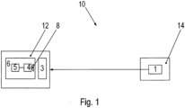
- FIG. 1 shows a schematic representation of a system 10 for light transmission.
- the system 10 for light transmission comprises a transmitter 14, which has a controllable light source 1.
- the light source 1 is, for example, an LED, a ceiling lamp or a headlight of a vehicle.
- the system 10 for light transmission further comprises a receiver 12.
- the receiver 12 comprises a camera 6.
- the camera 6 has an image sensor 4.
- the image sensor 4 has a light-sensitive surface which comprises several rows and columns of light-sensitive elements. When the camera 6 is in operation, the light-sensitive surface of the image sensor 4 is scanned line by line or column by column. The individual scanned lines are then put together to form an overall image.
- the camera 6 also comprises an optical element in the form of an optical lens 8.
- the lens 8 is arranged in front of the image sensor 4 so that light which strikes the light-sensitive surface of the image sensor 4 passes through the lens 8 first.
- the camera 6 also comprises signal electronics 5 which are used in particular to scan the light-sensitive surface of the image sensor 4.
- the receiver 12 also comprises an attachment element 3.
- the attachment element 3 is arranged in front of the image sensor 4 in such a way that light which strikes the light-sensitive surface of the image sensor 4 passes through the attachment element 3 beforehand.
- the attachment element 3 is designed in the form of a relatively thin, light-permeable film.
- the attachment element 3 is arranged between the light source 1 of the transmitter 14 and the camera 6.
- the camera 6 of the receiver 12 is, for example, part of a commercially available mobile phone or smartphone.
- the receiver 12 optionally also includes a recording unit.
- the recording unit is, for example, a case which has a first recording element and a second recording element.
- the second recording element is movable, in particular pivotable, relative to the first recording element.
- the mobile phone with the camera 6 is received in the first recording element, and the attachment element 3 is received in the second recording element.
- the attachment element 3 is thus movable, for example pivotable or displaceable, relative to the camera 6. If no data transmission via the system 10 is desired, the attachment element 3 can be removed from the camera 6, and the camera can record a complete optical image without the attachment element 3.
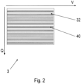
- Figure 2 shows a plan view of an attachment element 3.
- the attachment element 3 comprises a plurality of strip-shaped profiled regions 40 and a plurality of strip-shaped planar regions 32.
- the profiled regions 40 and the planar regions 32 are arranged alternately in a transverse direction Q and oriented parallel to a preferred direction V.
- the preferred direction V runs at right angles to the transverse direction Q.
- the strip-shaped profiled areas 40 of the attachment element 3 are designed in such a way that light which passes through the profiled areas 40 is refracted relatively strongly.
- a light beam 60 which originates from a point-shaped light source 1 is imaged in the form of a light strip 50 which runs in the transverse direction Q.
- Light which passes through the profiled areas 40 of the attachment element 3 creates a first image on the light-sensitive surface of the image sensor 4. The first image is blurred due to the relatively strong refraction of the light.
- the planar regions 32 of the attachment element 3 are designed in such a way that light which passes through the planar regions 32 penetrates the attachment element 3 at least approximately in a straight line, i.e. is not refracted or is only refracted insignificantly. Light which passes through the planar regions 32 of the attachment element 3 creates a second image on the light-sensitive surface of the image sensor 4.
- the second image is a sharp optical image.
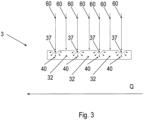
- Figure 3 shows a section through the Figure 2 shown attachment element 3.
- the section shown here runs in the transverse direction Q and perpendicular to the preferred direction V through the front element 3.
- the profiled regions 40 and the planar regions 32 are, as already mentioned, arranged alternately in the transverse direction Q.
- the planar regions 32 of the attachment element 3 have an at least approximately constant material thickness.
- the material thickness is an extension of the film in a direction perpendicular to the preferred direction V and perpendicular to the transverse direction Q. Light rays 60 thus penetrate the planar regions 32 at least approximately in a straight line and are not refracted or are refracted only insignificantly.
- the profiled areas 40 of the attachment element 3 have depressions 37 and are thus concave.
- the profiled areas 40 therefore have a lower material thickness than the planar areas 32.
- the profiled areas 40 have a constant cross-section throughout in the preferred direction V. In the present case, the profiled areas 40 have an approximately semicircular cross-section. Light rays 60 striking the profiled areas 40 are thus refracted in the transverse direction Q to varying degrees depending on the point of impact.
- the profiled areas 40 of the attachment element 3 have elevations and are thus convex.
- the profiled areas 40 have a greater material thickness than the planar areas 32.
- the cross-section of the profiled areas 40 can also deviate from the semicircular shape.
- An extension of the individual planar regions 32 in the transverse direction Y is greater than an extension of the individual profiled regions 40 in the transverse direction Y.
- the extension of the individual planar regions 32 in the transverse direction Y is approximately 4 ⁇ m
- the extension of the individual profiled regions 40 in the transverse direction Y is approximately 2 ⁇ m.
- the extension of the individual planar regions 32 in the transverse direction Y is therefore approximately three times as large as the extension of the individual profiled regions 40 in the transverse direction Y.
- the extension of the individual planar regions 32 in the transverse direction Y and the extension of the individual profiled regions 40 in the transverse direction Y should be less than 1 mm.
- FIG 4 shows a through the in Figure 2 and Figure 3 shown attachment element 3 projected overall image.
- the transmitter 14, which generates the overall image, is a motor vehicle.
- the said motor vehicle has two light sources 1, which serve as Headlights are designed.
- the two light sources 1 are to be regarded as approximately point-shaped.
- the said overall image comprises a first image which is generated by light passing through the profiled regions 40 of the attachment element 3.
- the overall image also comprises a second image which is generated by light passing through the planar regions 32 of the attachment element 3.
- the light strips 50 generated by the two light sources 1 extend in the transverse direction Q.
- the second image is a sharp optical image.
- the second image also shows relatively thin stripes with reduced brightness, which extend in the preferred direction V. These stripes are generated by parts of the profiled areas 40 of the attachment element 3, which are not hit by any light from the light sources 1. However, the said stripes are relatively thin and therefore barely visible in the overall image.
- the transmitter 14, in this case a motor vehicle, is thus clearly recognizable in the overall image.
Description
Die Erfindung betrifft einen Empfänger für ein System zur Lichtübertragung, umfassend eine Kamera, welche einen Bildsensor aufweist, wobei eine lichtsensitive Fläche des Bildsensors mehrere Zeilen von lichtsensitiven Elementen umfasst, wobei der Bildsensor derart ausgeführt ist, dass die lichtsensitive Fläche des Bildsensors zeilenweise oder spaltenweise abgetastet wird, und ein Vorsatzelement, welches derart angeordnet ist, dass auf die lichtsensitive Fläche des Bildsensors auftreffendes Licht zuvor das Vorsatzelement passiert. Die Erfindung betrifft auch ein System zur Lichtübertragung, umfassend einen erfindungsgemäßen Empfänger und einen Sender. Die Erfindung betrifft ferner ein Verfahren zum Betrieb eines erfindungsgemäßen Systems zur Lichtübertragung.The invention relates to a receiver for a system for light transmission, comprising a camera which has an image sensor, wherein a light-sensitive surface of the image sensor comprises several rows of light-sensitive elements, wherein the image sensor is designed such that the light-sensitive surface of the image sensor is scanned row by row or column by column, and an attachment element which is arranged such that light incident on the light-sensitive surface of the image sensor first passes through the attachment element. The invention also relates to a system for light transmission, comprising a receiver according to the invention and a transmitter. The invention further relates to a method for operating a system for light transmission according to the invention.
Aus dem Artikel "Using a CMOS Camera Sensor for Visible Light Communication", Danakis et. al., 978-1-4673-4941-3, IEEE, sind ein System und ein Verfahren zur Datenübertragung mittels sichtbarem Licht bekannt. Dabei dient eine Kamera eines Smartphones als Empfänger für sichtbares Licht. Die Kamera umfasst einen CMOS-Bildsensor, dessen lichtsensitive Fläche zeilenweise abgetastet wird. Als Sender dient eine Lichtquelle in Form einer LED, welche moduliertes Licht abstrahlt. Durch Ausnutzug des Rolling-Shutter-Effekts des CMOS-Bildsensors wird eine Datenübertragungsrate erzielt, welche größer ist als eine Bildfrequenz der Kamera.A system and a method for data transmission using visible light are known from the article "Using a CMOS Camera Sensor for Visible Light Communication", Danakis et al., 978-1-4673-4941-3, IEEE. A smartphone camera serves as a receiver for visible light. The camera includes a CMOS image sensor whose light-sensitive surface is scanned line by line. A light source in the form of an LED serves as the transmitter, emitting modulated light. By exploiting the rolling shutter effect of the CMOS image sensor, a data transmission rate is achieved that is higher than the frame rate of the camera.
Aus der
Aus dem Dokument
Aus der
Aus der
Aus der
Der Erfindung liegt die Aufgabe zugrunde, einen Empfänger für ein System zur Lichtübertragung, ein entsprechendes System und ein Verfahren zum Betrieb des Systems weiter zu bilden.The invention is based on the object of further developing a receiver for a system for light transmission, a corresponding system and a method for operating the system.
Die Aufgabe wird durch einen Empfänger für ein System zur Lichtübertragung mit den in Anspruch 1 angegebenen Merkmalen gelöst. Vorteilhafte Ausgestaltungen und Weiterbildungen sind Gegenstand der Unteransprüche. Die Aufgabe wird auch durch ein System zur Lichtübertragung mit den in Anspruch 10 angegebenen Merkmalen gelöst. Vorteilhafte Ausgestaltungen und Weiterbildungen sind Gegenstand der Unteransprüche. Die Aufgabe wird auch durch ein Verfahren zum Betrieb eines Systems zur Lichtübertragung mit den in Anspruch 12 angegebenen Merkmalen gelöst. Vorteilhafte Ausgestaltungen und Weiterbildungen sind Gegenstand der Unteransprüche.The object is achieved by a receiver for a light transmission system with the features specified in
Ein erfindungsgemäßer Empfänger für ein System zur Lichtübertragung umfasst eine Kamera, welche einen Bildsensor aufweist. Dabei umfasst eine lichtsensitive Fläche des Bildsensors mehrere Zeilen von lichtsensitiven Elementen. Der Bildsensor ist derart ausgeführt, dass die lichtsensitive Fläche des Bildsensors zeilenweise oder spaltenweise abgetastet wird. Der Empfänger umfasst auch ein Vorsatzelement. Das Vorsatzelement ist dabei derart angeordnet, dass auf die lichtsensitive Fläche des Bildsensors auftreffendes Licht zuvor das Vorsatzelement passiert.A receiver according to the invention for a system for light transmission comprises a camera which has an image sensor. A light-sensitive surface of the image sensor comprises several rows of light-sensitive elements. The image sensor is designed in such a way that the light-sensitive surface of the image sensor is scanned row by row or column by column. The receiver also comprises an attachment element. The attachment element is arranged in such a way that that light incident on the light-sensitive surface of the image sensor first passes through the attachment element.
Das Vorsatzelement umfasst eine Mehrzahl von streifenförmigen profilierten Bereichen und eine Mehrzahl von streifenförmigen planaren Bereichen. Dabei sind die profilierten Bereiche und die planaren Bereiche in einer Querrichtung abwechselnd angeordnet. Die profilierten Bereiche weisen in einer Vorzugsrichtung, welche rechtwinklig zu der Querrichtung verläuft, einen konstanten Querschnitt auf.The attachment element comprises a plurality of strip-shaped profiled regions and a plurality of strip-shaped planar regions. The profiled regions and the planar regions are arranged alternately in a transverse direction. The profiled regions have a constant cross-section in a preferred direction which runs at right angles to the transverse direction.
Licht, das die profilierten Bereiche des Vorsatzelements passiert, wird verhältnismäßig stark gebrochen und erzeugt ein erstes Bild auf der lichtsensitiven Fläche des Bildsensors. Das auf dem Bildsensor der Kamera erzeugte erste Bild ist daher ein unscharfes Bild. Insbesondere wird dabei ein Lichtstrahl, welcher von einer punktförmigen Lichtquelle stammt, in Form eines Leuchtstreifens abgebildet. Wenn moduliertes Licht eintrifft, so ist der besagte Leuchtstreifen in zeitlicher Abfolge hell und dunkel, in Abhängigkeit von der Modulation. Durch die zeilenweise oder spaltenweise Abtastung der lichtsensitiven Fläche des Bildsensors kann der Leuchtstreifen, in Abhängigkeit von der Modulation, somit helle und dunkele Bereiche aufweisen. Aus den hellen und dunklen Bereichen des besagten Leuchtstreifens kann ein Datenstrom detektiert werden, entsprechend welchem die Lichtquelle moduliertes Licht abstrahlt.Light that passes through the profiled areas of the attachment element is refracted relatively strongly and creates a first image on the light-sensitive surface of the image sensor. The first image created on the camera's image sensor is therefore a blurred image. In particular, a light beam originating from a point light source is imaged in the form of a light strip. When modulated light arrives, the light strip in question is light and dark in temporal sequence, depending on the modulation. By scanning the light-sensitive surface of the image sensor line by line or column by column, the light strip can have light and dark areas, depending on the modulation. A data stream can be detected from the light and dark areas of the light strip in question, according to which the light source emits modulated light.
Licht, das die planaren Bereiche des Vorsatzelements passiert, durchdringt das Vorsatzelement zumindest annährend geradlinig und erzeugt ein zweites Bild auf der lichtsensitiven Fläche des Bildsensors. Das auf dem Bildsensor der Kamera erzeugte zweite Bild ist daher ein scharfes optisches Bild.Light that passes through the planar areas of the attachment element penetrates the attachment element at least approximately in a straight line and creates a second image on the light-sensitive surface of the image sensor. The second image created on the camera's image sensor is therefore a sharp optical image.
Durch die erfindungsgemäße Ausgestaltung des Empfängers kann somit aus dem ersten Bild ein Datenstrom mit einer Datenübertragungsrate detektiert werden, welche größer ist als eine Bildfrequenz der Kamera des Empfängers. Aus dem zweiten Bild kann ein scharfes optisches Bild detektiert werden. Vorteilhaft ist der erfindungsgemäße Empfänger somit zur schnellen Datenübertragung und auch zur gleichzeitigen Aufnahme von scharfen optischen Bildern geeignet. Dabei ist das Vorsatzelement verhältnismäßig einfach und kostengünstig herstellbar.The receiver's design according to the invention means that a data stream can be detected from the first image at a data transmission rate that is greater than the frame rate of the receiver's camera. A sharp optical image can be detected from the second image. The receiver according to the invention is therefore advantageously suitable for fast data transmission and also for the simultaneous recording of sharp optical images. The attachment element can be manufactured relatively easily and inexpensively.
Gemäß einer bevorzugten Ausgestaltung der Erfindung ist das Vorsatzelement in Form einer Folie oder in Form einer Platte ausgebildet. Dabei weisen und die planaren Bereiche eine konstante Materialstärke auf. Die Folie oder die Platte ist dabei lichtdurchlässig.According to a preferred embodiment of the invention, the attachment element is designed in the form of a film or in the form of a plate. The planar areas have a constant material thickness. The film or plate is translucent.
Gemäß einer vorteilhaften Weiterbildung der Erfindung weisen die profilierten Bereiche Vertiefungen und somit eine geringere Materialstärke als die planaren Bereiche auf. Die profilierten Bereiche sind also konkav ausgestaltet. Dadurch wird erreicht, das die Brechung eines auftreffenden Lichtstrahls nicht überall gleich, sondern von dem Ort des Auftreffens abhängig ist. Das Vorsatzelement ist dabei besonders einfach und kostengünstig herstellbar, indem beispielsweise aus einer Folie oder aus einer Platte die Vertiefungen in Vorzugsrichtung durchgehend herausgefräst werden.According to an advantageous development of the invention, the profiled areas have depressions and thus a lower material thickness than the planar areas. The profiled areas are therefore concave. This ensures that the refraction of an incident light beam is not the same everywhere, but depends on the point of impact. The attachment element can be manufactured particularly easily and inexpensively, for example by milling the depressions out of a film or a plate in the preferred direction.
Gemäß einer anderen vorteilhaften Weiterbildung der Erfindung weisen die profilierten Bereiche Erhebungen und somit eine größere Materialstärke als die planaren Bereiche auf. Die profilierten Bereiche sind also konvex ausgestaltet. Dadurch wird erreicht, das die Brechung eines auftreffenden Lichtstrahls nicht überall gleich, sondern von dem Ort des Auftreffens abhängig ist.According to another advantageous development of the invention, the profiled areas have elevations and thus a greater material thickness than the planar areas. The profiled areas are therefore convex. This ensures that the refraction of an incident light beam is not the same everywhere, but depends on the point of impact.
Gemäß einer weiteren vorteilhaften Weiterbildung der Erfindung umfasst das Vorsatzelement profilierte Bereiche, welche Vertiefungen und somit eine geringere Materialstärke aufweisen als die planaren Bereiche und profilierte Bereiche, welche Erhebungen und somit eine größere Materialstärke aufweisen als die planaren Bereiche.According to a further advantageous development of the invention, the attachment element comprises profiled areas which have depressions and thus a smaller material thickness than the planar areas and profiled areas which have elevations and thus a greater material thickness than the planar areas.
Gemäß einer vorteilhaften Ausgestaltung der Erfindung weisen die profilierten Bereiche einen zumindest annähernd halbkreisförmigen Querschnitt auf.According to an advantageous embodiment of the invention, the profiled regions have an at least approximately semicircular cross-section.
Gemäß einer bevorzugten Ausgestaltung der Erfindung ist eine Ausdehnung eines der planaren Bereiche in der Querrichtung größer als eine Ausdehnung eines der profilierten Bereiche in der Querrichtung. Insbesondere ist eine Ausdehnung jedes der planaren Bereiche in der Querrichtung größer als eine Ausdehnung jedes der profilierten Bereiche in der Querrichtung.According to a preferred embodiment of the invention, an extension of one of the planar regions in the transverse direction is greater than an extension of one of the profiled regions in the transverse direction. In particular, an extension of each of the planar regions in the transverse direction is greater than an extension of each of the profiled regions in the transverse direction.
Besonders bevorzugt ist die Ausdehnung eines der planaren Bereiche in der Querrichtung mindestens doppelt so groß wie die Ausdehnung eines der profilierten Bereiche in der Querrichtung. Besonders bevorzugt ist ferner die Ausdehnung eines der planaren Bereiche in der Querrichtung höchstens zehnmal so groß wie die Ausdehnung eines der profilierten Bereiche in der Querrichtung. Insbesondere ist die Ausdehnung jedes der planaren Bereiche in der Querrichtung mindestens doppelt so groß wie die Ausdehnung jedes der profilierten Bereiche in der Querrichtung. Insbesondere ist ferner die Ausdehnung jedes der planaren Bereiche in der Querrichtung höchstens zehnmal so groß wie die Ausdehnung jedes der profilierten Bereiche in der Querrichtung.Particularly preferably, the extent of one of the planar regions in the transverse direction is at least twice as large as the extent of one of the profiled regions in the transverse direction. Furthermore, particularly preferably, the extent of one of the planar regions in the transverse direction is at most ten times as large as the extent of one of the profiled Regions in the transverse direction. In particular, the extent of each of the planar regions in the transverse direction is at least twice as large as the extent of each of the profiled regions in the transverse direction. In particular, furthermore, the extent of each of the planar regions in the transverse direction is at most ten times as large as the extent of each of the profiled regions in the transverse direction.
Gemäß einer vorteilhaften Weiterbildung der Erfindung umfasst der Empfänger ferner eine Aufnahmeeinheit. Die Aufnahmeeinheit weist ein erstes Aufnahmeelement und ein zweites Aufnahmeelement, welches relativ zu dem ersten Aufnahmeelement bewegbar ist, auf. Dabei ist die Kamera in dem ersten Aufnahmeelement aufgenommen, und das Vorsatzelement ist in dem zweiten Aufnahmeelement aufgenommen. Somit ist das Vorsatzelement relativ zu der Kamera bewegbar, beispielsweise schwenkbar oder verschiebbar.According to an advantageous development of the invention, the receiver further comprises a recording unit. The recording unit has a first recording element and a second recording element, which is movable relative to the first recording element. The camera is accommodated in the first recording element and the attachment element is accommodated in the second recording element. The attachment element is thus movable relative to the camera, for example pivotable or displaceable.
Ein erfindungsgemäßes System zur Lichtübertragung umfasst einen erfindungsgemäßen Empfänger und einen Sender, welcher mindestens eine steuerbare Lichtquelle aufweist. Die mindestens eine Lichtquelle des Senders strahlt dabei entsprechend einem vorgegebenen Datenstrom moduliertes Licht ab.A system for light transmission according to the invention comprises a receiver according to the invention and a transmitter which has at least one controllable light source. The at least one light source of the transmitter emits modulated light in accordance with a predetermined data stream.
Gemäß einer vorteilhaften Ausgestaltung der Erfindung ist das Vorsatzelement des Empfängers dabei zwischen der mindestens einen steuerbaren Lichtquelle des Senders und der Kamera des Empfängers angeordnet. Somit ist sichergestellt, dass Licht, welches auf die lichtsensitive Fläche des Bildsensors der Kamera auftrifft, zuvor das Vorsatzelement passiert.According to an advantageous embodiment of the invention, the attachment element of the receiver is arranged between the at least one controllable light source of the transmitter and the camera of the receiver. This ensures that light which strikes the light-sensitive surface of the image sensor of the camera first passes through the attachment element.
In einem erfindungsgemäßen Verfahren zum Betrieb eines erfindungsgemäßen Systems zur Lichtübertragung wird die lichtsensitive Fläche des Bildsensors zeilenweise oder spaltenweise abgetastet. Dabei wird ein erstes Bild, welches durch die profilierten Bereiche des Vorsatzelements auf die lichtsensitive Fläche projiziert wird, separat von einem zweiten Bild, welches durch die planaren Bereiche des Vorsatzelements auf die lichtsensitive Fläche projiziert wird, verarbeitet.In a method according to the invention for operating a system according to the invention for light transmission, the light-sensitive surface of the image sensor is scanned line by line or column by column. In this case, a first image, which is projected onto the light-sensitive surface by the profiled areas of the attachment element, is processed separately from a second image, which is projected onto the light-sensitive surface by the planar areas of the attachment element.
Gemäß einer vorteilhaften Ausgestaltung der Erfindung wird dabei aus dem ersten Bild der Datenstrom detektiert, entsprechend welchem die mindestens eine steuerbare Lichtquelle des Senders moduliertes Licht abstrahlt. Vorteilhaft ist die Datenübertragungsrate des Datenstroms dabei größer ist als eine Bildfrequenz der Kamera des Empfängers.According to an advantageous embodiment of the invention, the data stream is detected from the first image, according to which the at least one controllable light source of the transmitter emits modulated light. The data transmission rate of the data stream is advantageously greater than a frame rate of the camera of the receiver.
Gemäß einer vorteilhaften Ausgestaltung der Erfindung wird aus dem zweiten Bild ein optisches Bild detektiert. Vorteilhaft handelt es sich bei dem zweiten Bild dabei um ein scharfes optisches Bild.According to an advantageous embodiment of the invention, an optical image is detected from the second image. The second image is advantageously a sharp optical image.
Durch das erfindungsgemäße Verfahren können somit verschieden Informationen mittels des ersten Bildes und des zweiten Bildes gleichzeitig von dem Sender zu dem Empfänger übertragen und von dem Empfänger aufgenommen werden. Beispielsweise können in dem Datenstrom Koordinaten kodiert sein. Durch Auswertung des aus dem ersten Bild detektierten Datenstroms ist dann eine Ortung möglich. Durch Auswertung des zweiten Bildes kann beispielsweise ein QR-Code gescannt werden.Using the method according to the invention, different information can be transmitted from the transmitter to the receiver simultaneously using the first image and the second image and can be received by the receiver. For example, coordinates can be encoded in the data stream. By evaluating the data stream detected from the first image, location is then possible. By evaluating the second image, a QR code can be scanned, for example.
Die Erfindung ist nicht auf die Merkmalskombination der Ansprüche beschränkt. Für den Fachmann ergeben sich weitere sinnvolle Kombinationsmöglichkeiten von Ansprüchen und/oder einzelnen Anspruchsmerkmalen und/oder Merkmalen der Beschreibung und/oder der Figuren, insbesondere aus der Aufgabenstellung und/oder der sich durch Vergleich mit dem Stand der Technik stellenden Aufgabe.The invention is not limited to the combination of features in the claims. Other useful combination options of claims and/or individual claim features and/or features of the description and/or the figures will arise for the person skilled in the art, in particular from the task and/or the task arising from a comparison with the prior art.
Die Erfindung wird nun anhand von Abbildungen näher erläutert. Die Erfindung ist nicht auf die in den Abbildungen dargestellten Ausführungsbeispiele beschränkt. Die Abbildungen stellen den Gegenstand der Erfindung nur schematisch dar. Es zeigen:
- Figur 1:
- eine schematische Darstellung eines Systems zur Lichtübertragung,
- Figur 2:
- eine Draufsicht auf ein Vorsatzelement,
- Figur 3:
- einen Schnitt durch das Vorsatzelement und
- Figur 4:
- ein durch das Vorsatzelement projiziertes Gesamtbild.
- Figure 1:
- a schematic representation of a light transmission system,
- Figure 2:
- a top view of a front element,
- Figure 3:
- a section through the attachment element and
- Figure 4:
- an overall image projected through the attachment element.
Der Empfänger 12 umfasst eine Kamera 6. Die Kamera 6 weist einen Bildsensor 4 auf. Der Bildsensor 4 weist eine lichtsensitive Fläche auf, die mehrere Zeilen und Spalten von lichtsensitiven Elementen umfasst. Im Betrieb der Kamera 6 wird die lichtsensitive Fläche des Bildsensors 4 zeilenweise oder spaltenweise abgetastet. Die einzelnen abgetasteten Zeilen werden anschließend zu einem Gesamtbild zusammen gesetzt. Die Kamera 6 umfasst ferner ein optisches Element in Form einer optischen Linse 8. Die Linse 8 ist dabei vor dem Bildsensor 4 angeordnet, so dass Licht, welches auf die lichtsensitive Fläche des Bildsensors 4 auftrifft, zuvor die Linse 8 passiert. Die Kamera 6 umfasst auch eine Signalelektronik 5, welche insbesondere zum Abtasten der lichtsensitiven Fläche des Bildsensors 4 dient.The
Der Empfänger 12 umfasst auch ein Vorsatzelement 3. Das Vorsatzelement 3 ist derart vor dem Bildsensor 4 angeordnet, dass Licht, welches auf die lichtsensitive Fläche des Bildsensors 4 auftrifft, zuvor das Vorsatzelement 3 passiert. Das Vorsatzelement 3 ist in Form einer verhältnismäßig dünnen, lichtdurchlässigen Folie ausgebildet. Das Vorsatzelement 3 ist zwischen der Lichtquelle 1 des Senders 14 und der Kamera 6 angeordnet.The
Die Kamera 6 des Empfängers 12 ist beispielsweise Teil eines handelsüblichen Mobiltelefons oder Smartphones. Der Empfänger 12 umfasst optional auch eine Aufnahmeeinheit. Die Aufnahmeeinheit ist beispielsweise ein Etui, welches ein erstes Aufnahmeelement und ein zweites Aufnahmeelement aufweist. Dabei ist das zweite Aufnahmeelement relativ zu dem ersten Aufnahmeelement bewegbar, insbesondere schwenkbar. Das Mobiltelefon mit der Kamera 6 ist in dem ersten Aufnahmeelement aufgenommen, und das Vorsatzelement 3 ist in dem zweiten Aufnahmeelement aufgenommen. Somit ist das Vorsatzelement 3 relativ zu der Kamera 6 bewegbar, beispielsweise schwenkbar oder verschiebbar. Wenn keine Datenübertragung über das System 10 gewünscht ist, so kann das Vorsatzelement 3 von der Kamera 6 entfernt werden, und die Kamera kann ein vollständiges optisches Bild ohne das Vorsatzelement 3 aufnehmen.The
Die streifenförmigen profilierten Bereiche 40 des Vorsatzelements 3 sind derart ausgebildet, dass Licht, welches die profilierten Bereiche 40 passiert, verhältnismäßig stark gebrochen wird. Insbesondere wird dabei ein Lichtstrahl 60, welcher von einer punktförmigen Lichtquelle 1 stammt, in Form eines Leuchtstreifens 50, welcher in die Querrichtung Q verläuft, abgebildet. Licht, welches die profilierten Bereiche 40 des Vorsatzelements 3 passiert, erzeugt ein erstes Bild auf der lichtsensitiven Fläche des Bildsensors 4. Das erste Bild ist aufgrund der verhältnismäßig starken Brechung des Lichts unscharf.The strip-shaped profiled
Die planaren Bereiche 32 des Vorsatzelements 3 sind derart ausgebildet, dass Licht, welches die planaren Bereiche 32 passiert, das Vorsatzelement 3 zumindest annährend geradlinig durchdringt, also nicht oder nur unwesentlich gebrochen wird. Licht, welches die planaren Bereiche 32 des Vorsatzelements 3 passiert, erzeugt ein zweites Bild auf der lichtsensitiven Fläche des Bildsensors 4. Das zweite Bild ist ein scharfes optisches Bild.The
Die planaren Bereiche 32 des Vorsatzelements 3 weisen eine zumindest annähernd konstante Materialstärke auf. Die Materialstärke ist dabei eine Ausdehnung der Folie in einer Richtung rechtwinklig zu der Vorzugsrichtung V und rechtwinklig zu der Querrichtung Q. Somit durchdringen Lichtstrahlen 60 die planaren Bereiche 32 zumindest annährend geradlinig und werden nicht oder nur unwesentlich gebrochen.The
Die profilierten Bereiche 40 des Vorsatzelements 3 weisen Vertiefungen 37 auf und sind somit konkav ausgebildet. Die profilierten Bereiche 40 weisen somit eine geringere Materialstärke auf als die planaren Bereiche 32. Die profilierten Bereiche 40 weisen dabei in der Vorzugsrichtung V durchgehend einen konstanten Querschnitt auf. Vorliegend weisen die profilierten Bereiche 40 einen annähernd halbkreisförmigen Querschnitt auf. Auf die profilierten Bereiche 40 auftreffende Lichtstrahlen 60 werden somit in Abhängigkeit von der Stelle des Auftreffens unterschiedlich stark in die Querrichtung Q gebrochen.The profiled
Es ist auch denkbar, dass die profilierten Bereiche 40 des Vorsatzelements 3 Erhebungen aufweisen und somit konvex ausgebildet sind. In diesem Fall weisen die profilierten Bereiche 40 eine größere Materialstärke auf als die planaren Bereiche 32. Der Querschnitt der profilierten Bereiche 40 kann auch von der Halbkreisform abweichen.It is also conceivable that the profiled
Eine Ausdehnung der einzelnen planaren Bereiche 32 in der Querrichtung Y ist größer als eine Ausdehnung der einzelnen profilierten Bereiche 40 in der Querrichtung Y. Vorliegend beträgt die Ausdehnung der einzelnen planaren Bereiche 32 in der Querrichtung Y etwa 4 µm, und die Ausdehnung der einzelnen profilierten Bereiche 40 in der Querrichtung Y beträgt etwa 2 µm. Die Ausdehnung der einzelnen planaren Bereiche 32 in der Querrichtung Y ist vorliegend also etwa dreimal so groß wie die Ausdehnung der einzelnen profilierten Bereiche 40 in der Querrichtung Y. Die Ausdehnung der einzelnen planaren Bereiche 32 in der Querrichtung Y sowie die Ausdehnung der einzelnen profilierten Bereiche 40 in der Querrichtung Y sollte kleiner als 1 mm sein.An extension of the individual
Das besagte Gesamtbild umfasst ein erstes Bild, welches von Licht erzeugt wird, das die profilierten Bereiche 40 des Vorsatzelements 3 passiert. Das Gesamtbild umfasst auch ein zweites Bild, welches von Licht erzeugt wird, das die planaren Bereiche 32 des Vorsatzelements 3 passiert.The said overall image comprises a first image which is generated by light passing through the profiled
Das von einer der Lichtquellen 1 ausgestrahlte Licht, welches auf einen Teil eines profilierten Bereichs 40 des Vorsatzelements 3 trifft, wird gebrochen und in Form eines Leuchtstreifens 50 abgebildet. Die von den beiden Lichtquellen 1 erzeugten Leuchtstreifen 50 erstrecken sich dabei in die Querrichtung Q.The light emitted by one of the
Das von den übrigen Teilen des Senders 14 ausgestrahlte Licht, welches rechtwinklig auf einen planaren Bereich 32 des Vorsatzelements 3 trifft, durchdringt das Vorsatzelement 3 zumindest annährend geradlinig. Dadurch entsteht ein zweites Bild. Das zweite Bild ist dabei ein scharfes optisches Bild.The light emitted by the remaining parts of the
Das zweite Bild zeigt auch verhältnismäßig dünne Streifen mit verringerter Helligkeit, welche sich in die Vorzugsrichtung V erstrecken. Diese Streifen werden durch Teile der profilierten Bereiche 40 des Vorsatzelements 3 erzeugt, auf welche kein Licht der Lichtquellen 1 trifft. Die besagten Streifen sind jedoch verhältnismäßig dünn und daher in dem Gesamtbild kaum sichtbar. Somit ist der Sender 14, vorliegend ein Kraftfahrzeug, in dem Gesamtbild deutlich erkennbar.The second image also shows relatively thin stripes with reduced brightness, which extend in the preferred direction V. These stripes are generated by parts of the profiled
- 11
- LichtquelleLight source
- 33
- VorsatzelementAttachment element
- 44
- BildsensorImage sensor
- 55
- SignalelektronikSignal electronics
- 66
- Kameracamera
- 88th
- Linselens
- 1010
- Systemsystem
- 1212
- EmpfängerRecipient
- 1414
- SenderChannel
- 3232
- planarer Bereichplanar area
- 3737
- Vertiefungdeepening
- 4040
- profilierter Bereicheprofiled areas
- 5050
- LeuchtstreifenLight strips
- 6060
- Lichtstrahllight beam
- QuerrichtungTransverse direction
- VV
- VorzugsrichtungPreferred direction
Claims (14)
- Receiver (12) for a light transmission system (10), comprisinga camera (6) having an image sensor (4),a light-sensitive area of the image sensor (4) comprising a plurality of rows of light-sensitive elements,the image sensor (4) being configured such thatthe light-sensitive area of the image sensor (4) is scanned row by row or column by column, andan add-on element (3), which is arranged such thatlight impinging on the light-sensitive area of the image sensor (4) passes through the add-on element (3) first,the add-on element (3) comprising a plurality of strip-shaped profiled regions (40), andthe profiled regions (40) having a constant cross section in a preferential direction (V), which extends at right angles to a transverse direction (Q),characterised in thatthe add-on element (3) comprises a plurality of strip-shaped planar regions (32), and in that the profiled regions (40) and the planar regions (32) are arranged alternately in the transverse direction (Q).
- Receiver (12) according to claim 1,
characterised in that
the add-on element (3) is configured in the form of a film or in the form of a plate, the planar regions (32) having a constant material thickness. - Receiver (12) according to claim 2,
characterised in that
the profiled regions (40) have recesses (37) and a lower material thickness than the planar regions (32). - Receiver (12) according to claim 2,
characterised in that
the profiled regions (40) have bulges and a greater material thickness than the planar regions (32). - Receiver (12) according to claim 2,
characterised in thatthe add-on element (3) comprises profiled regions (40) that have recesses (37) and a lower material thickness than the planar regions (32), andprofiled regions (40) that have bulges and a greater material thickness than the planar regions (32). - Receiver (12) according to any of the preceding claims,
characterised in that
the profiled regions (40) have an at least approximately semicircular cross section. - Receiver (12) according to any of the preceding claims,
characterised in that
an extent of one of the planar regions (32) in the transverse direction (Y) is larger than an extent of one of the profiled regions (40) in the transverse direction (Y). - Receiver (12) according to any of the preceding claims,
characterised in thatthe extent of one of the planar regions (32) in the transverse direction (Y) is at least twice as large as the extent of one of the profiled regions (40) in the transverse direction (Y),
and/or in thatthe extent of one of the planar regions (32) in the transverse direction (Y) is at most ten times as large as the extent of one of the profiled regions (40) in the transverse direction (Y). - Receiver (12) according to any of the preceding claims,further comprising a supporting unit,characterised in thatthe supporting unit has a first supporting element and a second supporting element, which is movable relative to the first supporting element,the camera (6) being supported in the first supporting element, andthe add-on element (3) being supported in the second supporting element.
- Light transmission system (10) comprisinga receiver (12) according to at least one of the preceding claims anda transmitter (14), which has at least one controllable light source (1) that radiates modulated light in accordance with a predetermined data stream.
- System (10) according to claim 10,
characterised in that
the add-on element (3) is arranged between the at least one controllable light source (1) and the camera (6). - Method for operating a light transmission system (10) according to any of claims 10 to 11,
characterised in that
the light-sensitive area of the image sensor (4) is scanned row by row or column by column, a first image projected onto the light-sensitive area by the profiled regions (40) of the add-on element (3) being processed separately from a second image projected onto the light-sensitive area by the planar regions (32) of the add-on element (3). - Method according to claim 12,
characterised in that
the data stream is detected from the first image, the at least one controllable light source (1) of the transmitter (14) radiating modulated light in accordance with said data stream. - Method according to any of claims 12 to 13,
characterised in that
an optical image is detected from the second image.
Applications Claiming Priority (2)
| Application Number | Priority Date | Filing Date | Title |
|---|---|---|---|
| DE102020001892 | 2020-03-24 | ||
| PCT/EP2021/054800 WO2021190856A1 (en) | 2020-03-24 | 2021-02-26 | Receiver for a system for light transmission, system for light transmission and method for operating a system for light transmission |
Publications (2)
| Publication Number | Publication Date |
|---|---|
| EP4128583A1 EP4128583A1 (en) | 2023-02-08 |
| EP4128583B1 true EP4128583B1 (en) | 2024-04-10 |
Family
ID=74797933
Family Applications (1)
| Application Number | Title | Priority Date | Filing Date |
|---|---|---|---|
| EP21708623.0A Active EP4128583B1 (en) | 2020-03-24 | 2021-02-26 | Receiver for a system for light transmission, system for light transmission and method for operating a system for light transmission |
Country Status (5)
| Country | Link |
|---|---|
| US (1) | US20230164412A1 (en) |
| EP (1) | EP4128583B1 (en) |
| CN (1) | CN115136515A (en) |
| DE (1) | DE102021001049A1 (en) |
| WO (1) | WO2021190856A1 (en) |
Families Citing this family (1)
| Publication number | Priority date | Publication date | Assignee | Title |
|---|---|---|---|---|
| WO2024033028A1 (en) | 2022-08-10 | 2024-02-15 | Sew-Eurodrive Gmbh & Co. Kg | Method for determining a suitable line scanning frequency and system for transmitting light |
Family Cites Families (12)
| Publication number | Priority date | Publication date | Assignee | Title |
|---|---|---|---|---|
| KR100740483B1 (en) * | 2001-08-27 | 2007-07-19 | 가부시키가이샤 구라레 | Production method for lenticular lens sheet |
| JP3967251B2 (en) * | 2002-09-17 | 2007-08-29 | シャープ株式会社 | Electronic device having 2D (2D) and 3D (3D) display functions |
| JP4154263B2 (en) * | 2002-10-01 | 2008-09-24 | 株式会社ソフィア | Image display device and game machine equipped with image display device |
| US7957648B2 (en) | 2005-02-28 | 2011-06-07 | The Invention Science Fund I, Llc | Electromagnetic device with integral non-linear component |
| US9341014B2 (en) * | 2012-12-27 | 2016-05-17 | Panasonic Intellectual Property Corporation Of America | Information communication method using change in luminance |
| FR3020533A1 (en) * | 2014-04-29 | 2015-10-30 | Sunpartner Technologies | SEMI-TRANSPARENT ENCODED VISIBLE LIGHT COMMUNICATION DEVICE FOR VICUATING IMAGE THROUGH THE DEVICE AND RECEIVING SIMULTANEOUSLY MULTIPLE DIFFERENT ENCODED LIGHTS |
| US10482361B2 (en) * | 2015-07-05 | 2019-11-19 | Thewhollysee Ltd. | Optical identification and characterization system and tags |
| WO2018069867A1 (en) * | 2016-10-13 | 2018-04-19 | Six Degrees Space Ltd | Method and apparatus for indoor positioning |
| US10177848B1 (en) * | 2017-08-11 | 2019-01-08 | Abl Ip Holding Llc | Visual light communication using starburst or haze of the light source |
| US10348404B1 (en) * | 2018-05-09 | 2019-07-09 | Ford Global Technologies, Llc | Visible light communication system with pixel alignment for high data rate |
| US10382130B1 (en) * | 2018-08-31 | 2019-08-13 | Ford Global Technologies, Llc | Dual mode vehicle camera for visual light communication |
| DE102018006988B3 (en) | 2018-09-04 | 2019-08-14 | Sew-Eurodrive Gmbh & Co Kg | System and method of operating this system, comprising a first communication unit and a second communication unit |
-
2021
- 2021-02-26 WO PCT/EP2021/054800 patent/WO2021190856A1/en unknown
- 2021-02-26 US US17/913,588 patent/US20230164412A1/en active Pending
- 2021-02-26 DE DE102021001049.3A patent/DE102021001049A1/en active Pending
- 2021-02-26 EP EP21708623.0A patent/EP4128583B1/en active Active
- 2021-02-26 CN CN202180016043.7A patent/CN115136515A/en active Pending
Also Published As
| Publication number | Publication date |
|---|---|
| WO2021190856A1 (en) | 2021-09-30 |
| CN115136515A (en) | 2022-09-30 |
| US20230164412A1 (en) | 2023-05-25 |
| EP4128583A1 (en) | 2023-02-08 |
| DE102021001049A1 (en) | 2021-09-30 |
Similar Documents
| Publication | Publication Date | Title |
|---|---|---|
| EP2290355B1 (en) | Device and method for inspecting labelled containers | |
| DE102019005954A1 (en) | System and method for operating a system, comprising a first communication unit and a second communication unit | |
| EP4128583B1 (en) | Receiver for a system for light transmission, system for light transmission and method for operating a system for light transmission | |
| DE10217294A1 (en) | sensor orientation | |
| DE10026301A1 (en) | Image processing method and apparatus | |
| WO2004017016A2 (en) | Device and method for measuring the dimensions of a body | |
| EP2950519B1 (en) | Camera and method for capturing image data | |
| DE102016104255A1 (en) | Image reading device | |
| DE19936440A1 (en) | Optoelectronic device for detecting objects, uses transmitters to emit light rays, receiver to pick up transmitted light rays, and multiple receiving elements fitted at preset distances from each other | |
| DE102019007311B3 (en) | Receiver for a system for light transmission, system for light transmission and method for operating a system for light transmission | |
| EP1207491B1 (en) | Optoelectronic device | |
| EP2943377B1 (en) | Illumination for the detection of raindrops on a window by means of a camera | |
| EP1503226B1 (en) | Optical sensor | |
| WO2002067567A1 (en) | Device and method for linear illumination of an object using leds and an elliptical mirror | |
| EP0897123A2 (en) | Light barrier | |
| DE102023002931A1 (en) | Method for determining an appropriate line scanning frequency and system for transmitting light | |
| WO2006133972A1 (en) | Device for photographing coins in a coin validator | |
| DE102016219515A1 (en) | Time of flight camera system | |
| EP1130533A2 (en) | Scanner | |
| DE112006003116T5 (en) | Scanning device with guidance of light beams | |
| DE102005007283A1 (en) | Object distance measurement procedure uses lamp providing oscillating non repeating coded line pattern form array transducer base triangulation | |
| DE102015114575A1 (en) | Device for image control | |
| DE202022103565U1 (en) | Illumination device for generating an illumination field for a camera | |
| EP4300935A1 (en) | Lighting device for generating a lighting field for a camera | |
| DE202022104036U1 (en) | Code reading device |
Legal Events
| Date | Code | Title | Description |
|---|---|---|---|
| STAA | Information on the status of an ep patent application or granted ep patent |
Free format text: STATUS: UNKNOWN |
|
| STAA | Information on the status of an ep patent application or granted ep patent |
Free format text: STATUS: THE INTERNATIONAL PUBLICATION HAS BEEN MADE |
|
| PUAI | Public reference made under article 153(3) epc to a published international application that has entered the european phase |
Free format text: ORIGINAL CODE: 0009012 |
|
| STAA | Information on the status of an ep patent application or granted ep patent |
Free format text: STATUS: REQUEST FOR EXAMINATION WAS MADE |
|
| 17P | Request for examination filed |
Effective date: 20221024 |
|
| AK | Designated contracting states |
Kind code of ref document: A1 Designated state(s): AL AT BE BG CH CY CZ DE DK EE ES FI FR GB GR HR HU IE IS IT LI LT LU LV MC MK MT NL NO PL PT RO RS SE SI SK SM TR |
|
| DAV | Request for validation of the european patent (deleted) | ||
| DAX | Request for extension of the european patent (deleted) | ||
| GRAP | Despatch of communication of intention to grant a patent |
Free format text: ORIGINAL CODE: EPIDOSNIGR1 |
|
| STAA | Information on the status of an ep patent application or granted ep patent |
Free format text: STATUS: GRANT OF PATENT IS INTENDED |
|
| INTG | Intention to grant announced |
Effective date: 20231025 |
|
| GRAS | Grant fee paid |
Free format text: ORIGINAL CODE: EPIDOSNIGR3 |
|
| GRAA | (expected) grant |
Free format text: ORIGINAL CODE: 0009210 |
|
| STAA | Information on the status of an ep patent application or granted ep patent |
Free format text: STATUS: THE PATENT HAS BEEN GRANTED |
|
| AK | Designated contracting states |
Kind code of ref document: B1 Designated state(s): AL AT BE BG CH CY CZ DE DK EE ES FI FR GB GR HR HU IE IS IT LI LT LU LV MC MK MT NL NO PL PT RO RS SE SI SK SM TR |
|
| REG | Reference to a national code |
Ref country code: GB Ref legal event code: FG4D Free format text: NOT ENGLISH |
|
| REG | Reference to a national code |
Ref country code: CH Ref legal event code: EP |
|
| REG | Reference to a national code |
Ref country code: DE Ref legal event code: R096 Ref document number: 502021003307 Country of ref document: DE |