EP4300935A1 - Lighting device for generating a lighting field for a camera - Google Patents
Lighting device for generating a lighting field for a camera Download PDFInfo
- Publication number
- EP4300935A1 EP4300935A1 EP22181466.8A EP22181466A EP4300935A1 EP 4300935 A1 EP4300935 A1 EP 4300935A1 EP 22181466 A EP22181466 A EP 22181466A EP 4300935 A1 EP4300935 A1 EP 4300935A1
- Authority
- EP
- European Patent Office
- Prior art keywords
- lighting
- lens
- lighting device
- reflector
- transmitting
- Prior art date
- Legal status (The legal status is an assumption and is not a legal conclusion. Google has not performed a legal analysis and makes no representation as to the accuracy of the status listed.)
- Pending
Links
- 238000005286 illumination Methods 0.000 claims abstract description 67
- 238000011156 evaluation Methods 0.000 claims description 10
- 238000004519 manufacturing process Methods 0.000 claims description 7
- 230000010287 polarization Effects 0.000 claims description 7
- 239000004033 plastic Substances 0.000 claims description 6
- 229920003023 plastic Polymers 0.000 claims description 6
- 238000013461 design Methods 0.000 claims description 5
- 230000003287 optical effect Effects 0.000 claims description 5
- 229920003229 poly(methyl methacrylate) Polymers 0.000 claims description 5
- 239000004926 polymethyl methacrylate Substances 0.000 claims description 5
- 239000002184 metal Substances 0.000 claims description 4
- 230000003595 spectral effect Effects 0.000 claims description 4
- 238000000034 method Methods 0.000 claims 2
- 238000007493 shaping process Methods 0.000 description 6
- 238000012545 processing Methods 0.000 description 5
- 230000003213 activating effect Effects 0.000 description 4
- 230000004913 activation Effects 0.000 description 3
- 238000011161 development Methods 0.000 description 3
- 230000018109 developmental process Effects 0.000 description 3
- 238000010276 construction Methods 0.000 description 2
- 239000000463 material Substances 0.000 description 2
- 239000011159 matrix material Substances 0.000 description 2
- 238000012015 optical character recognition Methods 0.000 description 2
- 230000005855 radiation Effects 0.000 description 2
- 238000006243 chemical reaction Methods 0.000 description 1
- 238000000576 coating method Methods 0.000 description 1
- 239000003086 colorant Substances 0.000 description 1
- 238000001514 detection method Methods 0.000 description 1
- 238000007689 inspection Methods 0.000 description 1
- 238000003672 processing method Methods 0.000 description 1
- 238000003908 quality control method Methods 0.000 description 1
- 230000011218 segmentation Effects 0.000 description 1
- 239000004065 semiconductor Substances 0.000 description 1
- 238000009827 uniform distribution Methods 0.000 description 1
Images


Classifications
-
- G—PHYSICS
- G03—PHOTOGRAPHY; CINEMATOGRAPHY; ANALOGOUS TECHNIQUES USING WAVES OTHER THAN OPTICAL WAVES; ELECTROGRAPHY; HOLOGRAPHY
- G03B—APPARATUS OR ARRANGEMENTS FOR TAKING PHOTOGRAPHS OR FOR PROJECTING OR VIEWING THEM; APPARATUS OR ARRANGEMENTS EMPLOYING ANALOGOUS TECHNIQUES USING WAVES OTHER THAN OPTICAL WAVES; ACCESSORIES THEREFOR
- G03B15/00—Special procedures for taking photographs; Apparatus therefor
- G03B15/02—Illuminating scene
- G03B15/03—Combinations of cameras with lighting apparatus; Flash units
- G03B15/05—Combinations of cameras with electronic flash apparatus; Electronic flash units
-
- H—ELECTRICITY
- H04—ELECTRIC COMMUNICATION TECHNIQUE
- H04N—PICTORIAL COMMUNICATION, e.g. TELEVISION
- H04N23/00—Cameras or camera modules comprising electronic image sensors; Control thereof
- H04N23/56—Cameras or camera modules comprising electronic image sensors; Control thereof provided with illuminating means
Definitions
- the invention relates to a lighting device for generating an illumination field for a camera and a manufacturing method for a lighting device according to the preamble of claim 1 or 13.
- cameras are used in a variety of ways to automatically record object properties, for example for inspecting or measuring objects. Images of the object are taken and evaluated according to the task using image processing methods. Another application of cameras is reading codes. With the help of an image sensor, objects with the codes on them are recorded, the code areas are identified in the images and then decoded. Camera-based code readers can easily handle code types other than one-dimensional barcodes, which, like a matrix code, are also two-dimensional and provide more information.
- OCR Optical Character Recognition
- handwriting is, in principle, a reading of codes. Typical areas of application for code readers include supermarket checkouts, automatic package identification, sorting of mail, baggage handling in airports and other logistics applications.
- a common capture situation is mounting the camera above a conveyor belt.
- the camera records images during the relative movement of the object stream on the conveyor belt and initiates further processing steps depending on the object properties obtained.
- processing steps consist, for example, in further processing adapted to the specific object on a machine that acts on conveyed objects, or in a change in the flow of objects by certain Objects are removed from the object stream as part of a quality control or the object stream is sorted into several sub-object streams. If the camera is a camera-based code reader, the objects are identified by the attached codes for correct sorting or similar processing steps.
- the camera is often part of a complex sensor system. For example, in reading tunnels on conveyor belts, it is common to mount a large number of camera-based code readers next to each other on the one hand to cover a larger conveyor belt width and on the other hand from different perspectives in order to record objects from several sides. Furthermore, the geometry of the conveyed objects is often measured in advance with a separate laser scanner in order to determine focus information, trigger times, image areas with objects and the like.
- LEDs are often used as light sources. Compared to laser light sources, which are also occasionally used, LEDs usually have more divergent radiation characteristics and larger radiation areas. In order to direct their light specifically to the illumination field, appropriate optics are used.
- TIR lenses Total Internal Reflection
- a TIR lens has a geometry that ensures that the light entering it falls on the side surfaces at a sufficiently shallow angle to meet the total internal reflection conditions applicable to the lens material. This guides the light in a similar way to a light guide.
- a lighting device for generating an illumination field is known, which guides the light from its light source specifically into the illumination field using a TIR lens.
- TIR lenses can be too large, expensive, prone to tolerances and inflexible.
- an image recording device with adjustable illumination from multiple light sources is described.
- three beam shaping optics groups for object illumination are arranged alternately in a circular path around a receiving optics. By rotating the lens illumination, the appropriate one for the receiving optics used can be selected from these beam shaping optics groups by bringing them into alignment with the light sources.
- the individual beam shaping optics are not described in more detail.
- the EP 2 136 248 A1 deals with a line camera with a double line receiver and two lighting modules that are activated alternately to illuminate the detection area from different perspectives and possibly also in different colors. Once again, no detailed properties of the transmitting optics are discussed.
- the lighting device for generating an illumination field for a camera and a manufacturing method for a lighting device according to claim 1 or 13.
- the lighting device generates transmitted light with at least one light transmitter, preferably an LED or a laser diode.
- a reflector cone assigned to the light transmitter directs the transmitted light, which may have originally been emitted with a higher divergence, towards the front.
- the light transmitter is preferably arranged in the tip of the cone or at an opening in the tip of the cone, and the transmitted light is reflected forward by the reflector cone one or more times towards the base of the cone, unless it is already directed forward.
- the inner surface of the reflector cone is mirrored, so the transmitted light is reflected and not guided through total reflection as in a TIR lens.
- the invention is based on the basic idea of accommodating a transmitting lens in the reflector cone, which is used to shape the beam to a predetermined illumination angle of the lighting field.
- This transmitting lens is arranged on the base surface of the reflector cone opposite the tip of the cone.
- the transmitting lens closes off the base area, but due to tolerances or other reasons, for example design reasons, it is not necessarily flush and can therefore both dip into the reflector cone and protrude at least a little.
- the reflector cone and transmitter lens together form an illumination optics, with the reflector cone throwing the transmitted light forward and the transmitter lens further shaping the beam of the transmitted light according to the predetermined illumination angle.
- the invention has the advantage that particularly bright, powerful lighting is made possible.
- a large number of light emitters can be provided to further increase the light intensity. Nevertheless, the design remains compact.
- a good compromise has been found between homogeneity and efficiency.
- the lighting is less susceptible to tolerances and therefore offers even better performance.
- the same reflector cone can be connected to different transmitting lenses in order to facilitate the creation of variants, which in turn reduces the effort in development, production and administration.
- the reflector cone is preferably made of metal or coated plastic. This can be easily shaped into the required shape and has the required mirror properties. A metal surface can also be additionally processed or coated.
- the lighting device preferably has a plurality of light transmitters arranged in a ring, each with an associated reflector cone with an internally mirrored lateral surface and a transmitting lens arranged on its base surface. There are therefore preferably the same number of light transmitters, reflector cones and transmitting lenses. Each light transmitter with an associated reflector cone and transmitting lens can be viewed as a lighting element. Accordingly, the reflector cones and transmitting lenses together form the lighting optics for the large number of light transmitters.
- the lighting elements are arranged in a ring shape, namely in one ring or several concentric rings.
- the optical axis of the reception path of the camera preferably runs through the center of the ring or rings, whose field of view can thus be optimally illuminated.
- the lighting device preferably has a reflector base element with at least one ring arrangement of reflector cones mounted therein.
- the reflector base element itself is preferably annular or circular.
- the reflector cones form a compact, easy-to-handle common component. They are attached, for example, as conical recesses in the reflector base element.
- the arrangement of the reflector cones to form at least one circle or ring is preferably uniform. However, different distances in several rings and other irregularities or gaps are also conceivable.
- the reflector base element preferably has two reflector cones lying next to one another in the radial direction.
- the reflector cones are therefore provided in pairs in the radial direction and thus form a double ring overall, without excluding more than two rings.
- An intermediate wall can be provided between the two reflector cones of a pair lying radially next to one another, or both reflector cones merge into one another without an intermediate wall.
- a regular, continuous double ring is preferred, there may be deviations, such as places where a reflector cone is left without a partner.
- a transmitting lens with a different predetermined illumination angle can preferably be inserted into the at least one reflector cone.
- the same reflector cone can thus form an illumination optics for an illumination field with a different illumination angle by combining it with another transmitting lens.
- the lighting device is therefore part of a family of lighting devices or emerged from a lighting platform. Variants can be created or even conversions can be made without any additional development effort and with very little additional effort in production. If a large number of transmitting lenses are used in an arrangement of a large number of lighting elements, each individual transmitting lens does not necessarily have to generate the illumination angle, but this can only be done by superimposing the individual lighting fields of the transmitting lenses involved.
- the at least one transmitting lens is preferably made of plastic, in particular as an injection-molded part made of PMMA (polymethyl methacrylate). This enables cost-effective production that is also flexible in order to obtain transmitting lenses for different lighting angles.
- PMMA polymethyl methacrylate
- the transmitting lens preferably has a shape that fills the inner contour of the reflector cone.
- a transmitting lens with material in the area of the base area of the reflector rule is sufficient for beam shaping. However, if the transmitting lens fills the reflector cone, this results in a better fit with fewer tolerances, thus a more robust and simpler structure.
- the at least one transmitting lens is preferably designed as a double lens with a first lens and a second lens connected thereto.
- double lenses or lens doublets mean that fewer individual parts have to be designed, manufactured and connected to one another.
- the overall construction of the lighting device is simplified and there are fewer sources of possible disturbing tolerances.
- the lighting device preferably has a plurality of transmitting lenses arranged in a ring, with the double lenses each being arranged radially with the connecting line between the first lens and the second lens.
- the double lenses are therefore arranged transversely to the circumferential direction to form a double ring, with one angular segment of both rings being covered by a double lens.
- the reflector base element explained above with respective pairs of two reflector cones lying next to one another in the radial direction is particularly preferably used for this purpose. In principle, it would be conceivable as an alternative to arrange the double lenses in the circumferential direction instead of radially and thus form a single ring from only half as many individual parts as compared to single lenses.
- the lighting device preferably has a plurality of light transmitters which are interconnected in several lighting strands, in particular two or four lighting strands, with the lighting strands being able to be activated individually. This has the advantage that not too many light transmitters have to be supplied via the same line at the same time. Because the lighting strands can be activated individually, different lighting scenarios can be implemented.
- a first lighting strand is assigned to the left half and a second lighting strand to the right half of the lighting device.
- the lighting field can be generated either from one side, the other side or both sides.
- four lighting strands are preferably each assigned to a quarter of the lighting device, which creates numerous additional lighting perspectives.
- the division of the lighting device is particularly clear for a ring arrangement, in which case one lighting strand is assigned to a 180° segment or a 90° segment of the ring. It is also conceivable to assign the rings to different lighting strands in an arrangement as a double ring or multiple ring, although this can also be combined with segmentation of the rings.
- the light transmitters of a respective lighting strand are distributed over the entire ring, for example in alternately nested lighting strands. Then, by activating one or more lighting strands, essentially only the power can be varied while the lighting scenario remains largely unchanged in terms of perspective. If transmitting lenses are installed for different illumination angles, in particular a ring for a smaller and another ring for a larger illumination angle, the same illumination angles can be bundled into illumination strands, and the illumination angle can also be varied by appropriate activation of illumination strands.
- the light transmitters and/or optical elements arranged downstream of them in one lighting strand preferably generate transmitted light with different polarization properties and/or spectral properties than in another lighting strand.
- the different polarization properties or spectral properties can be generated directly by the light transmitter, for example using different colored LEDs, or color filters or polarization filters are arranged downstream, in particular in the form of corresponding characteristics or coatings of the respective transmitter lens.
- an illumination field of a desired polarization and/or color can be generated by targeted activation of certain lighting strands.
- a camera in particular a camera-based code reader or a camera for inspecting or measuring objects, which has an image sensor for recording image data, a control and evaluation unit for reading codes or determining object properties from the image data and an embodiment of the Has lighting device according to the invention.
- the field of view of the camera preferably corresponds to the illumination field of the illumination device, although the illumination field can be slightly larger to compensate for tolerances.
- the image evaluations or code reading can be carried out with multiple recordings in different lighting scenarios by activating certain ones lighting strands are taken as a basis.
- the control and evaluation unit can be part of the camera or connected to it as a control device. This functionality can also be distributed across the camera, lighting device and/or external control device.
- At least one light transmitter is arranged on or in the tip of a reflector cone assigned to the light transmitter with an internally mirrored lateral surface.
- a selection of different transmitting lenses suitable for the same design of the reflector cone for different illumination angles of the lighting device is kept and, in order to produce an illumination device for an illumination field of the specific illumination angle, a transmitting lens of the specific illumination angle is taken from the selection and arranged in the reflector cone on its base surface.
- the light transmitters and reflector cones form a type of lighting platform that can be easily adapted for different lighting fields and, in particular, lighting angles by combining them with different transmitting lenses.
- the various embodiments of the lighting device according to the invention can be implemented in this way.
- a plurality of transmitting lenses of the specific illumination angle are arranged in a reflector base element with at least one ring arrangement of reflector cones mounted therein. This easily creates a bright lighting device in a ring arrangement of the individual lighting elements at a desired lighting angle.
- the transmitting lenses are preferably produced as double lenses, each with a first lens and a second lens connected thereto, and the double lenses are each arranged with the connecting line between the first lens and the second lens radially in a reflector base element, each with two reflector cones lying next to one another in the radial direction.
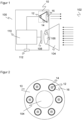
- Figure 1 shows a schematic sectional view of a lighting device 10 in a camera 100.
- an external lighting device is conceivable.
- the camera 100 can be used, for example, to measure or inspect objects as well as to capture codes and read out their contents.
- the camera 100 captures light from a recording area 102 through a recording lens 104, which is represented by only one receiving lens 106 shown as a representative of more complex recording lenses 104 with other optical elements such as apertures, prisms and the like.
- An image sensor 108 for example a CCD or CMOS chip with a large number of pixel elements arranged in a row or a matrix, generates image data of the recording area 102 and any objects and code areas that may be present there.
- a control and evaluation unit 110 is connected to the lighting device 10 and the image sensor 108 and is responsible for the control, evaluation and other coordination tasks in the camera 100, such as illuminating the recording area 102 and reading in image data from the image sensor 108.
- the Control and evaluation unit 110 is implemented on one or more digital components, for example microprocessors, ASICs, FPGAs or the like, which can also be provided completely or partially outside the camera 100.
- the control and evaluation unit 110 is able to locate and decode code areas in the image data, making the camera 100 a camera-based code reader.
- Data can be output at an output 112 of the camera 100, namely both evaluation results, such as read code information or determined dimensions and inspection results, as well as data in various processing stages, such as raw image data, pre-processed image data, identified objects or not yet decoded code image data.
- the lighting device 10 has a light transmitter 12 as a light source, a reflector cone 14 and a transmitting lens 16.
- semiconductor components such as an LED or a laser diode can be used as the light transmitter 12.
- the light transmitter 12 is arranged at the tip of the reflector cone 14. Deviating from the illustration, the light transmitter 12 can be arranged outside the reflector cone 14 or in an opening in its tip.
- the reflector cone 14 ensures that lateral parts of the transmitted light, which was originally emitted with a fairly high divergence, are brought forward through single or multiple reflection towards the base of the reflector cone 14 and thus the transmitter lens 16.
- the reflector cone 14 is mirrored on the inside, for example as a metal part with a reflective surface or as a correspondingly coated plastic part.
- the transmitting lens 16 shapes the transmitted light according to the desired illumination field and in particular illumination angle.
- the lighting device 10 is in Figure 1 especially with regard to their placement and design only shown purely schematically. In particular, a plurality of light transmitters 12 with associated lighting optics from the respective reflector cone 14 are preferred and transmitting lens 16 arranged around the taking lens 104. The lighting device 10 will now be described with reference to Figures 2 to 9 explained in detail.
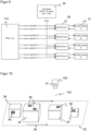
- Figure 2 shows a top view of an embodiment of the lighting device 10 with a plurality of ring-shaped lighting elements, each lighting element having a light transmitter 12, a reflector cone 14 and a transmitting lens 16.
- the illustration is purely an example with regard to the number of lighting elements and their arrangement on the ring, with a uniform distribution over the ring as shown being preferred. As explained later, there can be several rings of lighting elements and in particular a double ring.
- the center of the lighting device 10 preferably remains free, and the reception path with the recording lens 104 is accommodated here.
- the Figures 3a, 4a and 5a show different embodiments of the transmitting lens 16 for an average illumination angle of 31°, a larger illumination angle of 47° and a smaller illumination angle of 21°.
- the transmitting lenses 16 form a selection or family of transmitting lenses for different illumination angles, which can optionally be inserted into the reflector cone 14. This follows a platform idea in which the functions of forward reflection through the reflector cone 14 and the beam shaping to define the illumination angle through the transmitting lens 16 are more separated from one another.
- the appropriate transmitting lenses 16 are used or the existing transmitting lenses 16 are replaced, the reflector cone 14 remains the same or at least identical in construction.
- the transmitting lenses 16 preferably also have a lower section 18, which complements the transmitting lens 16 to form a cone shape.
- the external geometry of the transmitting lenses 16 remains the same despite different lighting angles, and the transmitting lenses 16 can be inserted into the reflector cone 14 with smaller tolerances.
- the correspondingly brightly shown section 18 can remain free and the corresponding shading shown can only be understood as an indication of the conical contour of the associated reflector cone 14.
- the Figures 3b, 4b and 5b show the transmitting lenses 16 in addition to exemplary associated beam paths 20 corresponding to the illumination angles of 31°, 47° and 21°.
- the illumination angles preferably correspond to the recording area 102 (FOV, Field of View), although a certain tolerance margin can be provided.
- the Figures 6a-b show further transmitting lenses 16 in a preferred embodiment as a double lens with a respective first lens 22 and second lens 24.
- the transmitting lens 16 generates according to Figure 6a corresponding to the average illumination angle of 31° Figure 3a-b and the transmitting lens 16 according to Figure 6b corresponding to the larger illumination angle of 47° Figure 4a-b .
- a further double lens, not shown, for the smaller illumination angle of 21° corresponding to 5a-b is also possible; the specific illumination angles are only to be understood as examples anyway.
- a high homogeneity of ⁇ 20° around the average value of the light field in the recording area 102 can be achieved.
- the double lenses or lens doublets reduce tolerances and the number of individual parts.
- Figure 7 shows a three-dimensional representation of a reflector base element 26 with radially adjacent pairs of reflector cones 14 and, purely by way of example, seventeen transmitting lenses 16 arranged in a ring to be accommodated therein, which correspond Figure 6a-b are designed as double lenses.
- the reflector base member 26 facilitates the arrangement of a plurality of reflector cones 14 into a desired arrangement such as a single or multiple preferably concentric ring arrangement. With the radial neighboring pairs of reflector cones 14 shown, a double ring is created.
- the transmitting lenses 16 are arranged appropriately so that the connecting line between the first lens 22 and the second lens 24 is aligned radially.
- Figure 8 additionally shows the lighting device 10 in the embodiment as a double ring of lighting elements, which after assembling the transmitting lenses 16 and the reflector base element 26 according to Figure 7 arises.
- FIG. 9 shows a schematic representation of the connection of a large number of light transmitters 12 in several, here for example four lighting strands.
- Each lighting strand has its own driver circuit 28, which in turn is controlled by the control and evaluation unit 110 or alternatively at least partially by an additional lighting control, not shown.
- the driver circuits 28 are connected to a supply 30 and make it possible to activate subgroups of the light transmitters 12 individually.
- the division into four subgroups or Lighting strands, each with eight light transmitters 12, as well as the total number of light transmitters 12, are to be understood purely as examples.
- the lighting strands simplify power management, because the common supply of a large number of light transmitters 12 could otherwise lead to problems.
- the targeted activation of specific lighting strands enables images to be captured under different lighting scenarios. Different aspects of the lighting can be varied individually or in combination. First, a lower or increased illuminance is achieved by activating a smaller or larger number of lighting strands. Then the light transmitters 12 of the respective lighting strands are geometrically distributed, so that lighting from different directions or perspectives is possible. For example, light transmitters 12 can be divided according to the two halves or the four quarters of a ring arrangement and/or the different rings and thus assigned to different lighting strands. Finally, the light emitters 12 of the lighting strings may differ in the light they produce, particularly in terms of polarization and color. This also makes lighting scenarios with different polarization properties and spectral properties possible by activating the corresponding lighting strands.
- Figure 10 shows a possible application of the camera 100 with lighting device 10 mounted on a conveyor belt 32.
- the camera 100 and the lighting device 10 are shown here only as a symbol and no longer with their structure already explained.
- the conveyor belt 32 conveys objects 34, as indicated by the arrow 36, through the recording area 102 of the camera 100. Any optically detectable properties of the objects 34 can be recorded and evaluated.
- the objects 34 carry code areas 38 on their outer surfaces.
- the task of the camera 100 is then to recognize the code areas 38, read out the codes attached there, decode them and assign them to the respective associated object 34.
- additional cameras (not shown) are preferably used from different perspectives.
- several cameras can be arranged next to each other in order to collectively cover a wider recording area 102.
Landscapes
- Physics & Mathematics (AREA)
- General Physics & Mathematics (AREA)
- Engineering & Computer Science (AREA)
- Multimedia (AREA)
- Signal Processing (AREA)
- Non-Portable Lighting Devices Or Systems Thereof (AREA)
Abstract
Es wird eine Beleuchtungsvorrichtung (10) zur Erzeugung eines Beleuchtungsfeldes für eine Kamera (100) angegeben, wobei die Beleuchtungsvorrichtung (10) mindestens einen Lichtsender (12) und einen dem Lichtsender (12) zugeordneten Reflektorkegel (14) mit innen verspiegelter Mantelfläche aufweist. Dabei ist in dem Reflektorkegel (14) an dessen Grundfläche eine Sendelinse (16) angeordnet, um ein Beleuchtungsfeld eines vorgegebenen Beleuchtungswinkels zu erzeugen.

Description
Die Erfindung betrifft eine Beleuchtungsvorrichtung zur Erzeugung eines Beleuchtungsfeldes für eine Kamera sowie ein Herstellungsverfahren für eine Beleuchtungsvorrichtung nach dem Oberbegriff von Anspruch 1 beziehungsweise 13.The invention relates to a lighting device for generating an illumination field for a camera and a manufacturing method for a lighting device according to the preamble of
In industriellen Anwendungen werden Kameras in vielfältiger Weise eingesetzt, um Objekteigenschaften automatisch zu erfassen, beispielsweise zur Inspektion oder Vermessung von Objekten. Dabei werden Bilder des Objekts aufgenommen und entsprechend der Aufgabe durch Bildverarbeitungsverfahren ausgewertet. Eine weitere Anwendung von Kameras ist das Lesen von Codes. Mit Hilfe eines Bildsensors werden Objekte mit den darauf befindlichen Codes aufgenommen, in den Bildern die Codebereiche identifiziert und dann dekodiert. Kamerabasierte Codeleser kommen problemlos auch mit anderen Codearten als eindimensionalen Strichcodes zurecht, die wie ein Matrixcode auch zweidimensional aufgebaut sind und mehr Informationen zur Verfügung stellen. Auch die automatische Texterfassung von gedruckten Adressen (OCR, Optical Character Recognition) oder Handschriften ist im Prinzip ein Lesen von Codes. Typische Anwendungsgebiete von Codelesern sind Supermarktkassen, die automatische Paketidentifikation, Sortierung von Postsendungen, die Gepäckabfertigung in Flughäfen und andere Logistikanwendungen.In industrial applications, cameras are used in a variety of ways to automatically record object properties, for example for inspecting or measuring objects. Images of the object are taken and evaluated according to the task using image processing methods. Another application of cameras is reading codes. With the help of an image sensor, objects with the codes on them are recorded, the code areas are identified in the images and then decoded. Camera-based code readers can easily handle code types other than one-dimensional barcodes, which, like a matrix code, are also two-dimensional and provide more information. The automatic text capture of printed addresses (OCR, Optical Character Recognition) or handwriting is, in principle, a reading of codes. Typical areas of application for code readers include supermarket checkouts, automatic package identification, sorting of mail, baggage handling in airports and other logistics applications.
Eine häufige Erfassungssituation ist die Montage der Kamera über einem Förderband. Die Kamera nimmt während der Relativbewegung des Objektstroms auf dem Förderband Bilder auf und leitet in Abhängigkeit der gewonnenen Objekteigenschaften weitere Bearbeitungsschritte ein. Solche Bearbeitungsschritte bestehen beispielsweise in der an das konkrete Objekt angepassten Weiterverarbeitung an einer Maschine, die auf geförderte Objekte einwirkt, oder in einer Veränderung des Objektstroms, indem bestimmte Objekte im Rahmen einer Qualitätskontrolle aus dem Objektstrom ausgeschleust werden oder der Objektstrom in mehrere Teilobjektströme sortiert wird. Wenn die Kamera ein kamerabasierter Codeleser ist, werden die Objekte für eine korrekte Sortierung oder ähnliche Bearbeitungsschritte anhand der angebrachten Codes identifiziert.A common capture situation is mounting the camera above a conveyor belt. The camera records images during the relative movement of the object stream on the conveyor belt and initiates further processing steps depending on the object properties obtained. Such processing steps consist, for example, in further processing adapted to the specific object on a machine that acts on conveyed objects, or in a change in the flow of objects by certain Objects are removed from the object stream as part of a quality control or the object stream is sorted into several sub-object streams. If the camera is a camera-based code reader, the objects are identified by the attached codes for correct sorting or similar processing steps.
Die Kamera ist vielfach Teil eines komplexen Sensorsystems. Beispielsweise ist es bei Lesetunneln an Förderbändern üblich, eine Vielzahl von kamerabasierten Codelesern einerseits nebeneinander zur Abdeckung einer größeren Förderbandbreite und andererseits aus unterschiedlichen Perspektiven zu montieren, um Objekte von mehreren Seiten aufzunehmen. Weiterhin wird oftmals die Geometrie der geförderten Objekte vorab mit einem gesonderten Laserscanner vermessen, um daraus Fokusinformationen, Auslösezeitpunkte, Bildbereiche mit Objekten und dergleichen zu bestimmen.The camera is often part of a complex sensor system. For example, in reading tunnels on conveyor belts, it is common to mount a large number of camera-based code readers next to each other on the one hand to cover a larger conveyor belt width and on the other hand from different perspectives in order to record objects from several sides. Furthermore, the geometry of the conveyed objects is often measured in advance with a separate laser scanner in order to determine focus information, trigger times, image areas with objects and the like.
Kameras und Kamerasysteme benötigen eine Beleuchtung, um die zu inspizierenden oder zu vermessenden Objekte beziehungsweise den zu lesenden Code unabhängig von Umgebungs- oder Fremdlicht erfassen zu können. Als Lichtquellen werden dabei häufig LEDs verwendet. Im Vergleich zu den ebenfalls gelegentlich verwendeten Laserlichtquellen haben LEDs meist eine divergentere Abstrahlcharakteristik und größere Abstrahlflächen. Um deren Licht dennoch gezielt auf das Beleuchtungsfeld zu führen, werden entsprechende Optiken verwendet.Cameras and camera systems require lighting in order to be able to capture the objects to be inspected or measured or the code to be read, regardless of ambient or extraneous light. LEDs are often used as light sources. Compared to laser light sources, which are also occasionally used, LEDs usually have more divergent radiation characteristics and larger radiation areas. In order to direct their light specifically to the illumination field, appropriate optics are used.
Für eine gute Signalqualität, d.h. in erster Linie ein ausreichendes Signal-Rausch-Verhältnis, ist eine starke und möglichst homogene Beleuchtung erforderlich. Dabei besteht ein gewisses Spannungsverhältnis zwischen Homogenität und Effizienz, zwischen denen ein annehmbarer Kompromiss gefunden werden muss. Da Kameras in einer großen Variantenvielfalt gebraucht werden, die sich in Eigenschaften wie der Auflösung des Bildsensors, in Sichtfeld und Arbeitsabstand differenzieren, besteht ebenso ein Bedarf an unterschiedlichen Beleuchtungen.For good signal quality, i.e. primarily a sufficient signal-to-noise ratio, strong and as homogeneous lighting as possible is required. There is a certain tension between homogeneity and efficiency, between which an acceptable compromise must be found. Since cameras are needed in a large variety of variants, which differ in properties such as the resolution of the image sensor, field of view and working distance, there is also a need for different lighting.
Bisher wurden hier sogenannte TIR-Linsen (Total Internal Reflection) eingesetzt. Eine TIR-Linse weist eine Geometrie auf, die dafür sorgt, dass das eingetretene Licht in hinreichend flachem Winkel auf die Seitenflächen fällt, um die für das Linsenmaterial geltenden Bedingungen für Totalreflexion zu erfüllen. Dadurch wird das Licht ähnlich wie in einem Lichtleiter geführt. Beispielsweise offenbart die
In der
Die
Es ist daher Aufgabe der Erfindung, die Beleuchtung für eine Kamera weiter zu verbessern.It is therefore the object of the invention to further improve the lighting for a camera.
Diese Aufgabe wird durch eine Beleuchtungsvorrichtung zur Erzeugung eines Beleuchtungsfeldes für eine Kamera sowie ein Herstellungsverfahren für eine Beleuchtungsvorrichtung nach Anspruch 1 beziehungsweise 13 gelöst. Die Beleuchtungsvorrichtung erzeugt Sendelicht mit mindestens einem Lichtsender, vorzugsweise einer LED oder einer Laserdiode. Ein dem Lichtsender zugeordneter Reflektorkegel richtet das womöglich ursprünglich noch mit höherer Divergenz abgestrahlte Sendelicht nach vorne hin aus. Der Lichtsender ist dafür vorzugsweise in der Kegelspitze oder an einer Öffnung der Kegelspitze angeordnet, und Sendelicht wird von dem Reflektorkegel ein- oder mehrfach nach vorne zur Grundfläche des Kegels hin gespiegelt, soweit es nicht ohnehin schon nach vorne gerichtet ist. Die innere Mantelfläche des Reflektorkegels ist verspiegelt, das Sendelicht wird somit reflektiert und nicht wie in einer TIR-Linse durch Totalreflexion geführt.This object is achieved by a lighting device for generating an illumination field for a camera and a manufacturing method for a lighting device according to
Die Erfindung geht von dem Grundgedanken aus, in dem Reflektorkegel eine Sendelinse unterzubringen, die für eine Strahlformung auf einen vorgegebenen Beleuchtungswinkel des Beleuchtungsfeldes sorgt. Diese Sendelinse ist an der der Kegelspitze gegenüberliegenden Grundfläche des Reflektorkegels angeordnet. Vorzugsweise schließt die Sendelinse die Grundfläche ab, wobei sie durch Toleranzen oder sonstige, beispielsweise konstruktive Gründe nicht notwendig bündig abschließt und somit sowohl in den Reflektorkegel eintauchen als auch zumindest ein wenig herausragen kann. Reflektorkegel und Sendelinse bilden gemeinsam eine Beleuchtungsoptik, wobei der Reflektorkegel das Sendelicht nach vorne wirft und die Sendelinse das Strahlenbündel des Sendelichts entsprechend dem vorgegebenen Beleuchtungswinkel weiter formt.The invention is based on the basic idea of accommodating a transmitting lens in the reflector cone, which is used to shape the beam to a predetermined illumination angle of the lighting field. This transmitting lens is arranged on the base surface of the reflector cone opposite the tip of the cone. Preferably, the transmitting lens closes off the base area, but due to tolerances or other reasons, for example design reasons, it is not necessarily flush and can therefore both dip into the reflector cone and protrude at least a little. The reflector cone and transmitter lens together form an illumination optics, with the reflector cone throwing the transmitted light forward and the transmitter lens further shaping the beam of the transmitted light according to the predetermined illumination angle.
Die Erfindung hat den Vorteil, dass eine besonders helle, lichtstarke Beleuchtung ermöglicht wird. Es kann eine große Anzahl von Lichtsendern vorgesehen werden, um die Lichtstärke noch zu erhöhen. Dennoch bleibt die Bauform kompakt. Dabei ist ein guter Kompromiss zwischen Homogenität und Effizienz gefunden. Die Beleuchtung ist wenig anfällig gegenüber Toleranzen und bietet so eine noch bessere Leistung. Wie später noch genauer erläutert, kann derselbe Reflektorkegel mit unterschiedlichen Sendelinsen verbunden werden, um dadurch die Variantenbildung zu erleichtern, was wiederum den Aufwand in Entwicklung, Produktion und Verwaltung reduziert.The invention has the advantage that particularly bright, powerful lighting is made possible. A large number of light emitters can be provided to further increase the light intensity. Nevertheless, the design remains compact. A good compromise has been found between homogeneity and efficiency. The lighting is less susceptible to tolerances and therefore offers even better performance. As explained in more detail later, the same reflector cone can be connected to different transmitting lenses in order to facilitate the creation of variants, which in turn reduces the effort in development, production and administration.
Der Reflektorkegel ist bevorzugt aus Metall oder beschichtetem Kunststoff hergestellt. Das lässt sich leicht in die erforderliche Form bringen und hat die erforderlichen Spiegeleigenschaften. Auch eine Metalloberfläche kann zusätzlich bearbeitet beziehungsweise beschichtet werden.The reflector cone is preferably made of metal or coated plastic. This can be easily shaped into the required shape and has the required mirror properties. A metal surface can also be additionally processed or coated.
Die Beleuchtungsvorrichtung weist bevorzugt eine Vielzahl ringförmig angeordneter Lichtsender mit jeweils einem zugeordneten Reflektorkegel mit innen verspiegelter Mantelfläche und einer an dessen Grundfläche angeordneten Sendelinse auf. Es gibt demnach bevorzugt gleich viele Lichtsender, Reflektorkegel und Sendelinsen. Jeweils ein Lichtsender mit zugeordnetem Reflektorkegel samt Sendelinse können als ein Beleuchtungselement aufgefasst werden. Entsprechend bilden die Reflektorkegel und Sendelinsen gemeinsam die Beleuchtungsoptik für die Vielzahl von Lichtsendern. Die Beleuchtungselemente werden in dieser Ausführungsform ringförmig angeordnet, und zwar in einem Ring oder mehreren konzentrischen Ringen. Durch das Zentrum des Rings oder der Ringe verläuft vorzugsweise die optische Achse des Empfangspfads der Kamera, deren Sichtfeld somit optimal ausgeleuchtet werden kann.The lighting device preferably has a plurality of light transmitters arranged in a ring, each with an associated reflector cone with an internally mirrored lateral surface and a transmitting lens arranged on its base surface. There are therefore preferably the same number of light transmitters, reflector cones and transmitting lenses. Each light transmitter with an associated reflector cone and transmitting lens can be viewed as a lighting element. Accordingly, the reflector cones and transmitting lenses together form the lighting optics for the large number of light transmitters. In this embodiment, the lighting elements are arranged in a ring shape, namely in one ring or several concentric rings. The optical axis of the reception path of the camera preferably runs through the center of the ring or rings, whose field of view can thus be optimally illuminated.
Die Beleuchtungsvorrichtung weist bevorzugt ein Reflektorbasiselement mit mindestens einer darin angebrachten Ringanordnung von Reflektorkegeln auf. Dabei ist das Reflektorbasiselement vorzugsweise selbst ringförmig beziehungsweise kreisförmig ausgebildet. Die Reflektorkegel bilden auf diese Weise ein kompaktes, gut handhabbares gemeinsames Bauteil. Sie werden beispielsweise als kegelförmige Aussparungen in dem Reflektorbasiselement angebracht. Die Anordnung der Reflektorkegel zu mindestens einem Kreis oder Ring ist vorzugsweise gleichmäßig. Es sind aber auch unterschiedliche Abstände in mehreren Ringen und sonstige Unregelmäßigkeiten oder Lücken denkbar.The lighting device preferably has a reflector base element with at least one ring arrangement of reflector cones mounted therein. The reflector base element itself is preferably annular or circular. In this way, the reflector cones form a compact, easy-to-handle common component. They are attached, for example, as conical recesses in the reflector base element. The arrangement of the reflector cones to form at least one circle or ring is preferably uniform. However, different distances in several rings and other irregularities or gaps are also conceivable.
Das Reflektorbasiselement weist bevorzugt jeweils in radialer Richtung zwei nebeneinanderliegende Reflektorkegel auf. Die Reflektorkegel sind somit in radialer Richtung paarweise vorgesehen und bilden damit insgesamt einen Doppelring, ohne damit mehr als zwei Ringe auszuschließen. Zwischen den beiden Reflektorkegeln eines radial nebeneinander liegenden Paares kann eine Zwischenwand vorgesehen sein, oder beide Reflektorkegel gehen ohne Zwischenwand ineinander über. Obwohl ein regelmäßiger, durchgehender Doppelring bevorzugt ist, kann es Abweichungen geben, beispielsweise Stellen, in denen ein Reflektorkegel ohne Partner bleibt.The reflector base element preferably has two reflector cones lying next to one another in the radial direction. The reflector cones are therefore provided in pairs in the radial direction and thus form a double ring overall, without excluding more than two rings. An intermediate wall can be provided between the two reflector cones of a pair lying radially next to one another, or both reflector cones merge into one another without an intermediate wall. Although a regular, continuous double ring is preferred, there may be deviations, such as places where a reflector cone is left without a partner.
In den mindestens einen Reflektorkegel ist bevorzugt wahlweise eine Sendelinse mit einem anderen vorgegebenen Beleuchtungswinkel einsetzbar. Derselbe Reflektorkegel kann somit durch Kombination mit einer anderen Sendelinse eine Beleuchtungsoptik für ein Beleuchtungsfeld mit einem anderen Beleuchtungswinkel bilden. Die Beleuchtungsvorrichtung ist damit Teil einer Familie von Beleuchtungsvorrichtungen oder aus einer Beleuchtungsplattform entstanden. Es können ohne zusätzlichen Entwicklungsaufwand und mit äußerst wenig Zusatzaufwand in der Herstellung Varianten gebildet oder sogar Umrüstungen vorgenommen werden. Sofern eine Vielzahl von Sendelinsen in einer Anordnung einer Vielzahl von Beleuchtungselementen zum Einsatz kommt, muss nicht zwingend jede einzelne Sendelinse den Beleuchtungswinkel erzeugen, sondern dies kann erst durch die Überlagerung der einzelnen Beleuchtungsfelder der beteiligten Sendelinsen erfolgen.A transmitting lens with a different predetermined illumination angle can preferably be inserted into the at least one reflector cone. The same reflector cone can thus form an illumination optics for an illumination field with a different illumination angle by combining it with another transmitting lens. The lighting device is therefore part of a family of lighting devices or emerged from a lighting platform. Variants can be created or even conversions can be made without any additional development effort and with very little additional effort in production. If a large number of transmitting lenses are used in an arrangement of a large number of lighting elements, each individual transmitting lens does not necessarily have to generate the illumination angle, but this can only be done by superimposing the individual lighting fields of the transmitting lenses involved.
Die mindestens eine Sendelinse ist bevorzugt aus Kunststoff hergestellt, insbesondere als Spritzgussteil aus PMMA (Polymethylmethacrylat). Das ermöglicht eine kostengünstige Herstellung, die zugleich flexibel ist, um Sendelinsen für unterschiedliche Beleuchtungswinkel zu erhalten.The at least one transmitting lens is preferably made of plastic, in particular as an injection-molded part made of PMMA (polymethyl methacrylate). This enables cost-effective production that is also flexible in order to obtain transmitting lenses for different lighting angles.
Die Sendelinse weist bevorzugt eine die Innenkontur des Reflektorkegels füllende Form auf. Für die Strahlformung genügt eine Sendelinse mit Material im Bereich der Grundfläche des Reflektoregels. Wenn aber die Sendelinse den Reflektorkegel füllt, so ergibt sich eine bessere Passform bei weniger Toleranzen, somit ein robusterer und einfacherer Aufbau.The transmitting lens preferably has a shape that fills the inner contour of the reflector cone. A transmitting lens with material in the area of the base area of the reflector rule is sufficient for beam shaping. However, if the transmitting lens fills the reflector cone, this results in a better fit with fewer tolerances, thus a more robust and simpler structure.
Die mindestens eine Sendelinse ist bevorzugt als Doppellinse mit einer ersten Linse und einer damit verbundenen zweiten Linse ausgebildet. Durch solche Doppellinsen oder Linsendoubletten sind weniger Einzelteile zu entwerfen, herzustellen und miteinander zu verbinden. Der Gesamtaufbau der Beleuchtungsvorrichtung wird vereinfacht, und es gibt weniger Quellen für mögliche störende Toleranzen.The at least one transmitting lens is preferably designed as a double lens with a first lens and a second lens connected thereto. Such double lenses or lens doublets mean that fewer individual parts have to be designed, manufactured and connected to one another. The overall construction of the lighting device is simplified and there are fewer sources of possible disturbing tolerances.
Die Beleuchtungsvorrichtung weist bevorzugt eine Vielzahl ringförmig angeordneter Sendelinsen auf, wobei die Doppellinsen jeweils mit der Verbindungslinie zwischen erster Linse und zweiter Linse radial angeordnet sind. Die Doppellinsen werden also quer zur Umfangsrichtung zu einem Doppelring angeordnet, wobei jeweils ein Winkelsegment beider Ringe von einer Doppellinse abgedeckt wird. Besonders bevorzugt wird dazu das oben erläuterte Reflektorbasiselement mit jeweiligen Paaren von zwei in radialer Richtung nebeneinanderliegenden Reflektorkegeln verwendet. Es wäre grundsätzlich alternativ denkbar, die Doppellinsen statt radial in Umfangsrichtung anzuordnen und so einen einzigen Ring aus im Vergleich zu Einzellinsen nur halb so vielen Einzelteilen zu bilden.The lighting device preferably has a plurality of transmitting lenses arranged in a ring, with the double lenses each being arranged radially with the connecting line between the first lens and the second lens. The double lenses are therefore arranged transversely to the circumferential direction to form a double ring, with one angular segment of both rings being covered by a double lens. The reflector base element explained above with respective pairs of two reflector cones lying next to one another in the radial direction is particularly preferably used for this purpose. In principle, it would be conceivable as an alternative to arrange the double lenses in the circumferential direction instead of radially and thus form a single ring from only half as many individual parts as compared to single lenses.
Die Beleuchtungsvorrichtung weist bevorzugt eine Vielzahl von Lichtsendern auf, die in mehreren Beleuchtungssträngen, insbesondere zwei oder vier Beleuchtungssträngen, miteinander verschaltet sind, wobei die Beleuchtungsstränge einzeln aktivierbar sind. Das hat einmal den Vorteil, dass nicht zu viele Lichtsender zugleich über denselben Strang versorgt werden müssen. Indem die Beleuchtungsstränge einzelnen aktivierbar sind, können zudem unterschiedliche Beleuchtungsszenarien verwirklicht werden.The lighting device preferably has a plurality of light transmitters which are interconnected in several lighting strands, in particular two or four lighting strands, with the lighting strands being able to be activated individually. This has the advantage that not too many light transmitters have to be supplied via the same line at the same time. Because the lighting strands can be activated individually, different lighting scenarios can be implemented.
Vorzugsweise ist ein erster Beleuchtungsstrang der linken Hälfte und ein zweiter Beleuchtungsstrang der rechten Hälfte der Beleuchtungsvorrichtung zugeordnet. Dadurch kann das Beleuchtungsfeld wahlweise von der einen Seite, der anderen Seite oder beiden Seiten erzeugt werden. In einer weiteren Ausführungsform sind vorzugsweise vier Beleuchtungsstränge jeweils einem Viertel der Beleuchtungsvorrichtung zugeordnet, womit zahlreiche weitere Beleuchtungsperspektiven entstehen. Die Aufteilung der Beleuchtungsvorrichtung ist besonders anschaulich für eine Ringanordnung, wobei dann jeweils ein Beleuchtungsstrang einem 180°-Segment beziehungsweise einem 90°-Segment des Rings zugeordnet ist. Denkbar ist auch, in einer Anordnung als Doppelring oder Mehrfachring die Ringe unterschiedlichen Beleuchtungssträngen zuzuordnen, wobei dies auch mit einer Segmentierung der Ringe kombinierbar ist. In einer weiteren Alternative sind die Lichtsender eines jeweiligen Beleuchtungsstrangs über den gesamten Ring verteilt, beispielsweise in alternierend ineinander verschachtelten Beleuchtungssträngen. Dann kann durch Aktivierung eines oder mehrerer Beleuchtungsstränge im Wesentlichen nur die Leistung variiert werden und dabei das Beleuchtungsszenario hinsichtlich der Perspektive weitgehend beibehalten bleiben. Sind Sendelinsen für unterschiedliche Beleuchtungswinkel verbaut, insbesondere ein Ring für einen kleineren und ein weiterer Ring für einen größeren Beleuchtungswinkel, so können gleiche Beleuchtungswinkel jeweils in Beleuchtungssträngen gebündelt werden, und so kann durch entsprechende Aktivierung von Beleuchtungssträngen auch der Beleuchtungswinkel variiert werden.Preferably, a first lighting strand is assigned to the left half and a second lighting strand to the right half of the lighting device. This means that the lighting field can be generated either from one side, the other side or both sides. In a further embodiment, four lighting strands are preferably each assigned to a quarter of the lighting device, which creates numerous additional lighting perspectives. The division of the lighting device is particularly clear for a ring arrangement, in which case one lighting strand is assigned to a 180° segment or a 90° segment of the ring. It is also conceivable to assign the rings to different lighting strands in an arrangement as a double ring or multiple ring, although this can also be combined with segmentation of the rings. In a further alternative, the light transmitters of a respective lighting strand are distributed over the entire ring, for example in alternately nested lighting strands. Then, by activating one or more lighting strands, essentially only the power can be varied while the lighting scenario remains largely unchanged in terms of perspective. If transmitting lenses are installed for different illumination angles, in particular a ring for a smaller and another ring for a larger illumination angle, the same illumination angles can be bundled into illumination strands, and the illumination angle can also be varied by appropriate activation of illumination strands.
Die Lichtsender und/oder ihnen nachgeordnete optische Elemente in einem Beleuchtungsstrang erzeugen bevorzugt Sendelicht mit anderen Polarisationseigenschaften und/oder spektralen Eigenschaften als in einem anderen Beleuchtungsstrang. Die unterschiedlichen Polarisationseigenschaften beziehungsweise spektralen Eigenschaften können unmittelbar vom Lichtsender erzeugt werden, beispielsweise durch verschiedenfarbige LEDs, oder es werden Farbfilter beziehungsweise Polarisationsfilter nachgeordnet, insbesondere in Form entsprechender Ausprägungen oder Beschichtungen der jeweiligen Sendelinse. Durch gezielte Aktivierung bestimmter Beleuchtungsstränge kann in dieser Ausführungsform ein Beleuchtungsfeld einer gewünschten Polarisation und/oder Farbe erzeugt werden. Diese Lichteigenschaften des Beleuchtungsfeldes sind mit den im Vorabsatz erläuterten geometrischen Eigenschaften kombinierbar.The light transmitters and/or optical elements arranged downstream of them in one lighting strand preferably generate transmitted light with different polarization properties and/or spectral properties than in another lighting strand. The different polarization properties or spectral properties can be generated directly by the light transmitter, for example using different colored LEDs, or color filters or polarization filters are arranged downstream, in particular in the form of corresponding characteristics or coatings of the respective transmitter lens. In this embodiment, an illumination field of a desired polarization and/or color can be generated by targeted activation of certain lighting strands. These light properties of the lighting field can be combined with the geometric properties explained in the previous paragraph.
In bevorzugter Weiterbildung ist eine Kamera, insbesondere ein kamerabasierter Codeleser oder eine Kamera zur Inspektion oder Vermessung von Objekten vorgesehen, die einen Bildsensor zur Aufnahme von Bilddaten, eine Steuer- und Auswertungseinheit zum Lesen von Codes oder Bestimmen von Objekteigenschaften aus den Bilddaten und eine Ausführungsform der erfindungsgemäßen Beleuchtungsvorrichtung aufweist. Das Sichtfeld der Kamera entspricht vorzugsweise dem Beleuchtungsfeld der Beleuchtungsvorrichtung, wobei zum Ausgleich von Toleranzen das Beleuchtungsfeld etwas größer sein kann. Den Bildauswertungen beziehungsweise dem Codelesen können Mehrfachaufnahmen bei unterschiedlichen Beleuchtungsszenarien durch Aktivierung bestimmter Beleuchtungsstränge zugrunde gelegt werden. Die Steuer- und Auswertungseinheit kann Teil der Kamera oder als Steuerungsgerät daran angeschlossen sein. Diese Funktionalität kann weiterhin über Kamera, Beleuchtungsvorrichtung und/oder externes Steuerungsgerät verteilt sein.In a preferred development, a camera, in particular a camera-based code reader or a camera for inspecting or measuring objects, is provided, which has an image sensor for recording image data, a control and evaluation unit for reading codes or determining object properties from the image data and an embodiment of the Has lighting device according to the invention. The field of view of the camera preferably corresponds to the illumination field of the illumination device, although the illumination field can be slightly larger to compensate for tolerances. The image evaluations or code reading can be carried out with multiple recordings in different lighting scenarios by activating certain ones lighting strands are taken as a basis. The control and evaluation unit can be part of the camera or connected to it as a control device. This functionality can also be distributed across the camera, lighting device and/or external control device.
Bei dem erfindungsgemäßen Herstellungsverfahren für eine Beleuchtungsvorrichtung wird mindestens ein Lichtsender an oder in der Spitze eines dem Lichtsender zugeordneten Reflektorkegels mit innen verspiegelter Mantelfläche angeordnet. Es wird eine Auswahl von unterschiedlichen, für dieselbe Bauform des Reflektorkegels passende Sendelinsen für verschiedene Beleuchtungswinkel der Beleuchtungsvorrichtung vorgehalten und zur Herstellung einer Beleuchtungsvorrichtung für ein Beleuchtungsfeld des bestimmten Beleuchtungswinkels eine Sendelinse des bestimmten Beleuchtungswinkels aus der Auswahl entnommen und in dem Reflektorkegel an dessen Grundfläche angeordnet. Die Lichtsender und Reflektorkegel bilden eine Art Beleuchtungsplattform, die durch Kombination mit unterschiedlichen Sendelinsen sehr einfach für verschiedene Beleuchtungsfelder und insbesondere Beleuchtungswinkel angepasst werden können. Auf diese Weise sind insbesondere die verschiedenen Ausführungsformen der erfindungsgemäßen Beleuchtungsvorrichtung realisierbar.In the manufacturing method according to the invention for a lighting device, at least one light transmitter is arranged on or in the tip of a reflector cone assigned to the light transmitter with an internally mirrored lateral surface. A selection of different transmitting lenses suitable for the same design of the reflector cone for different illumination angles of the lighting device is kept and, in order to produce an illumination device for an illumination field of the specific illumination angle, a transmitting lens of the specific illumination angle is taken from the selection and arranged in the reflector cone on its base surface. The light transmitters and reflector cones form a type of lighting platform that can be easily adapted for different lighting fields and, in particular, lighting angles by combining them with different transmitting lenses. In particular, the various embodiments of the lighting device according to the invention can be implemented in this way.
Vorzugsweise wird eine Vielzahl von Sendelinsen des bestimmten Beleuchtungswinkels in ein Reflektorbasiselement mit mindestens einer darin angebrachten Ringanordnung von Reflektorkegeln angeordnet. Es entsteht so auf einfache Weise eine lichtstarke Beleuchtungsvorrichtung in Ringanordnung der einzelnen Beleuchtungselemente eines gewünschten Beleuchtungswinkels.Preferably, a plurality of transmitting lenses of the specific illumination angle are arranged in a reflector base element with at least one ring arrangement of reflector cones mounted therein. This easily creates a bright lighting device in a ring arrangement of the individual lighting elements at a desired lighting angle.
Die Sendelinsen werden bevorzugt als Doppellinsen mit jeweils einer ersten Linse und einer damit verbundenen zweiten Linse hergestellt, und die Doppellinsen werden jeweils mit der Verbindungslinie zwischen erster Linse und zweiter Linse radial in ein Reflektorbasiselement mit jeweils zwei in radialer Richtung nebeneinanderliegenden Reflektorkegeln angeordnet. Dadurch entsteht mit weniger Einzelteilen und folglich weniger Aufwand und Toleranzen eine Beleuchtungsvorrichtung mit einer Anordnung der Beleuchtungselemente in einem Doppelring.The transmitting lenses are preferably produced as double lenses, each with a first lens and a second lens connected thereto, and the double lenses are each arranged with the connecting line between the first lens and the second lens radially in a reflector base element, each with two reflector cones lying next to one another in the radial direction. This creates a lighting device with an arrangement of the lighting elements in a double ring with fewer individual parts and consequently less effort and tolerances.
Die Erfindung wird nachstehend auch hinsichtlich weiterer Merkmale und Vorteile beispielhaft anhand von Ausführungsformen und unter Bezug auf die beigefügte Zeichnung näher erläutert. Die Abbildungen der Zeichnung zeigen in:
- Fig. 1
- eine schematische Schnittdarstellung einer Kamera mit einer Beleuchtungsvorrichtung;
- Fig. 2
- eine Draufsicht auf eine Beleuchtungsvorrichtung mit ringförmig angeordneten Beleuchtungselementen;
- Fig. 3a
- eine Darstellung einer Sendelinse für einen mittleren Beleuchtungswinkel;
- Fig. 3b
- ein beispielhafter Strahlverlauf des Sendelichts bei Verwendung der Sendelinse gemäß
Figur 3a ; - Fig. 4a
- eine Darstellung einer Sendelinse für einen größeren Beleuchtungswinkel;
- Fig. 4b
- ein beispielhafter Strahlverlauf des Sendelichts bei Verwendung der Sendelinse gemäß
Figur 4a ; - Fig. 5a
- eine Darstellung einer Sendelinse für einen kleineren Beleuchtungswinkel;
- Fig. 5b
- ein beispielhafter Strahlverlauf des Sendelichts bei Verwendung der Sendelinse gemäß
Figur 5a ; - Fig. 6a
- eine Darstellung einer Doppellinse als Sendelinse für den mittleren Beleuchtungswinkel entsprechend
Figur 3a-b ; - Fig. 6b
- eine Darstellung einer Doppellinse als Sendelinse für den größeren Beleuchtungswinkel entsprechend
Figur 4a-b ; - Fig. 7
- eine dreidimensionale Darstellung eines Reflektorbasiselements mit radial benachbarten Paaren von Reflektorkegeln sowie einer ringförmigen Anordnung darin unterzubringender Doppellinsen;
- Fig. 8
- ein Doppelring von Beleuchtungselementen, der nach Einsetzen der Doppellinsen in das Reflektorbasiselement gemäß
Figur 7 entsteht; - Fig. 9
- eine schematische Darstellung der Verschaltung von Lichtquellen in mehreren Beleuchtungssträngen; und
- Fig. 10
- eine dreidimensionale Ansicht der beispielhaften Anwendung einer Kamera mit einer Beleuchtungsvorrichtung in Montage an einem Förderband.
- Fig. 1
- a schematic sectional view of a camera with a lighting device;
- Fig. 2
- a top view of a lighting device with lighting elements arranged in a ring;
- Fig. 3a
- a representation of a transmitting lens for a medium illumination angle;
- Fig. 3b
- an exemplary beam path of the transmitted light when using the transmitting lens
Figure 3a ; - Fig. 4a
- a representation of a transmitting lens for a larger angle of illumination;
- Fig. 4b
- an exemplary beam path of the transmitted light when using the transmitting lens
Figure 4a ; - Fig. 5a
- a representation of a transmitting lens for a smaller angle of illumination;
- Fig. 5b
- an exemplary beam path of the transmitted light when using the transmitting lens
Figure 5a ; - Fig. 6a
- a representation of a double lens as a transmitting lens for the average illumination angle
Figure 3a-b ; - Fig. 6b
- a representation of a double lens as a transmitting lens for the larger illumination angle
Figure 4a-b ; - Fig. 7
- a three-dimensional representation of a reflector base element with radially adjacent pairs of reflector cones and an annular arrangement of double lenses to be accommodated therein;
- Fig. 8
- a double ring of lighting elements, which after inserting the double lenses into the reflector base element according to
Figure 7 arises; - Fig. 9
- a schematic representation of the connection of light sources in several lighting strands; and
- Fig. 10
- a three-dimensional view of the exemplary application of a camera with a lighting device mounted on a conveyor belt.
Die Kamera 100 erfasst Licht aus einem Aufnahmebereich 102 durch ein Aufnahmeobjektiv 104, das durch nur eine dargestellte Empfangslinse 106 stellvertretend auch für komplexere Aufnahmeobjektive 104 mit anderen optischen Elementen wie Blenden, Prismen und dergleichen repräsentiert ist. Ein Bildsensor 108, beispielsweise ein CCD- oder CMOS-Chip mit einer Vielzahl von zu einer Zeile oder einer Matrix angeordneten Pixelelementen, erzeugt Bilddaten des Aufnahmebereichs 102 und der dort gegebenenfalls vorhandenen Objekte und Codebereiche. Eine Steuer- und Auswertungseinheit 110 ist mit der Beleuchtungsvorrichtung 10 und dem Bildsensor 108 verbunden und für die Steuerungs-, Auswertungs- und sonstigen Koordinierungsaufgaben in der Kamera 100 zuständig, wie das Beleuchten des Aufnahmebereichs 102 und das Einlesen von Bilddaten von dem Bildsensor 108. Die Steuer- und Auswertungseinheit 110 ist auf einem oder mehreren digitalen Bausteinen implementiert, beispielsweise Mikroprozessoren, ASICs, FPGAs oder dergleichen, die auch ganz oder teilweise außerhalb der Kamera 100 vorgesehen sein können. Vorzugsweise ist die Steuer- und Auswertungseinheit 110 in der Lage, Codebereiche in den Bilddaten aufzufinden und zu decodieren, womit die Kamera 100 zu einem kamerabasierten Codeleser wird. An einem Ausgang 112 der Kamera 100 können Daten ausgegeben werden, und zwar sowohl Auswertungsergebnisse, wie gelesene Codeinformationen oder ermittelte Abmessungen und Inspektionsergebnisse, als auch Daten in verschiedenen Verarbeitungsstufen, wie Rohbilddaten, vorverarbeitete Bilddaten, identifizierte Objekte oder noch nicht decodierte Codebilddaten.The
Die Beleuchtungsvorrichtung 10 weist einen Lichtsender 12 als Lichtquelle, einen Reflektorkegel 14 und eine Sendelinse 16 auf. Als Lichtsender 12 können insbesondere Halbleiterbauteile wie eine LED oder eine Laserdiode eingesetzt werden. Der Lichtsender 12 ist an der Spitze des Reflektorkegels 14 angeordnet. Abweichend von der Darstellung kann der Lichtsender 12 außerhalb des Reflektorkegels 14 an beziehungsweise in einer Öffnung in dessen Spitze angeordnet sein. Der Reflektorkegel 14 sorgt dafür, dass auch seitliche Anteile des ursprünglich mit recht hoher Divergenz abgestrahlten Sendelichts durch einfache oder mehrfache Reflexion nach vorne in Richtung der Grundfläche des Reflektorkegels 14 und damit der Sendelinse 16 gebracht werden. Dafür ist der Reflektorkegel 14 innen verspiegelt, beispielsweise als Metallteil mit spiegelnder Oberfläche oder als entsprechend beschichtetes Kunststoffteil. Die Sendelinse 16 formt das Sendelicht entsprechend dem gewünschten Beleuchtungsfeld und insbesondere Beleuchtungswinkel. Als Sendelinse 16 wird vorzugsweise ein Spritzgussteil aus Kunststoff eingesetzt, beispielsweise aus PMMA (Polymethylmethacrylat). Die Beleuchtungsvorrichtung 10 ist in
Die
Die
Die
Durch die Beleuchtungsstränge ist zum einen das Leistungsmanagement vereinfacht, denn die gemeinsame Versorgung einer großen Anzahl von Lichtsendern 12 könnte andernfalls zu Problemen führen. Außerdem ermöglicht die gezielte Aktivierung bestimmter Beleuchtungsstränge die Aufnahme von Bildern unter verschiedenen Beleuchtungsszenarien. Variiert werden können verschiedene Aspekte der Beleuchtung einzeln oder in Kombination. Zunächst wird durch Aktivierung einer kleineren oder größeren Anzahl von Beleuchtungssträngen eine geringere oder erhöhte Beleuchtungsstärke erreicht. Dann sind die Lichtsender 12 der jeweiligen Beleuchtungsstränge geometrisch verteilt, so dass Beleuchtungen aus unterschiedlichen Richtungen oder Perspektiven ermöglicht werden. Beispielsweise können Lichtsender 12 entsprechend den zwei Hälften oder den vier Vierteln einer Ringanordnung und/oder den unterschiedlichen Ringen aufgeteilt und so unterschiedlichen Beleuchtungssträngen zugeordnet werden. Schließlich können sich die Lichtsender 12 der Beleuchtungsstränge in dem Licht unterscheiden, das sie erzeugen, insbesondere im Hinblick auf Polarisation und Farbe. Dadurch sind auch Beleuchtungsszenarien mit unterschiedlichen Polarisationseigenschaften und spektralen Eigenschaften durch Aktivierung der entsprechenden Beleuchtungsstränge möglich.On the one hand, the lighting strands simplify power management, because the common supply of a large number of
Claims (15)
dadurch gekennzeichnet,
dass in dem Reflektorkegel (14) an dessen Grundfläche eine Sendelinse (16) angeordnet ist, um ein Beleuchtungsfeld eines vorgegebenen Beleuchtungswinkels zu erzeugen.Illumination device (10) for generating an illumination field for a camera (100), the illumination device (10) having at least one light transmitter (12) and a reflector cone (14) assigned to the light transmitter (12) with an internally mirrored lateral surface,
characterized,
that a transmitting lens (16) is arranged in the reflector cone (14) on its base surface in order to generate an illumination field of a predetermined illumination angle.
wobei der Reflektorkegel (14) aus Metall oder beschichtetem Kunststoff hergestellt ist.Lighting device (10) according to claim 1,
wherein the reflector cone (14) is made of metal or coated plastic.
die eine Vielzahl ringförmig angeordneter Lichtsender (12) mit jeweils einem zugeordneten Reflektorkegel (14) mit innen verspiegelter Mantelfläche und einer an dessen Grundfläche angeordneten Sendelinse (16) aufweist.Lighting device (10) according to claim 1 or 2,
which has a plurality of light transmitters (12) arranged in a ring, each with an associated reflector cone (14) with an internally mirrored lateral surface and a transmitter lens (16) arranged on its base surface.
wobei das Reflektorbasiselement (26) jeweils in radialer Richtung zwei nebeneinanderliegende Reflektorkegel (14) aufweist.Lighting device (10) according to claim 4,
wherein the reflector base element (26) has two adjacent reflector cones (14) in the radial direction.
und/oder wobei die Sendelinse (16) eine die Innenkontur des Reflektorkegels (14) füllende Form (18) aufweist.Lighting device (10) according to one of the preceding claims, wherein the at least one transmitting lens (16) is made of plastic, in particular as an injection-molded part made of PMMA
and/or wherein the transmitting lens (16) has a shape (18) that fills the inner contour of the reflector cone (14).
die eine Vielzahl ringförmig angeordneter Sendelinsen (16) aufweist, wobei die Doppellinsen jeweils mit der Verbindungslinie zwischen erster Linse (22) und zweiter Linse (24) radial angeordnet sind.Lighting device (10) according to claim 8,
which has a plurality of annularly arranged transmitting lenses (16), the double lenses each being arranged radially with the connecting line between the first lens (22) and the second lens (24).
dadurch gekennzeichnet,
dass eine Auswahl von unterschiedlichen, für dieselbe Bauform des Reflektorkegels (14) passende Sendelinsen (16) für verschiedene Beleuchtungswinkel der Beleuchtungsvorrichtung (10) vorgehalten wird und dass zur Herstellung einer Beleuchtungsvorrichtung (10) für ein Beleuchtungsfeld des bestimmten Beleuchtungswinkels eine Sendelinse (16) des bestimmten Beleuchtungswinkels aus der Auswahl entnommen und in dem Reflektorkegel (14) an dessen Grundfläche angeordnet wird.Method for producing a lighting device (10), in particular a lighting device (10) according to one of the preceding claims, in which at least one light transmitter (12) is arranged on or in the tip of a reflector cone (14) assigned to the light transmitter (12) with an internally mirrored lateral surface,
characterized,
that a selection of different transmitting lenses (16) suitable for the same design of the reflector cone (14) is kept available for different illumination angles of the lighting device (10) and that in order to produce a lighting device (10) for an illumination field of the specific illumination angle, a transmitting lens (16) of the certain lighting angle is taken from the selection and arranged in the reflector cone (14) on its base.
wobei eine Vielzahl von Sendelinsen (16) des bestimmten Beleuchtungswinkels in ein Reflektorbasiselement (26) mit mindestens einer darin angebrachten Ringanordnung von Reflektorkegeln (14) angeordnet wird.Method according to claim 13,
wherein a plurality of transmitting lenses (16) of the specific illumination angle are arranged in a reflector base element (26) with at least one ring arrangement of reflector cones (14) mounted therein.
wobei die Sendelinsen (16) als Doppellinsen mit jeweils einer ersten Linse (22) und einer damit verbundenen zweiten Linse (24) hergestellt werden und die Doppellinsen jeweils mit der Verbindungslinie zwischen erster Linse (22) und zweiter Linse (24) radial in ein Reflektorbasiselement (26) mit jeweils zwei in radialer Richtung nebeneinanderliegenden Reflektorkegeln (14) angeordnet werden.Method according to claim 13 or 14,
wherein the transmitting lenses (16) are produced as double lenses, each with a first lens (22) and a second lens (24) connected thereto, and the double lenses are each radially inserted into a reflector base element with the connecting line between the first lens (22) and the second lens (24). (26) can be arranged with two reflector cones (14) lying next to one another in the radial direction.
Priority Applications (1)
| Application Number | Priority Date | Filing Date | Title |
|---|---|---|---|
| EP22181466.8A EP4300935A1 (en) | 2022-06-28 | 2022-06-28 | Lighting device for generating a lighting field for a camera |
Applications Claiming Priority (1)
| Application Number | Priority Date | Filing Date | Title |
|---|---|---|---|
| EP22181466.8A EP4300935A1 (en) | 2022-06-28 | 2022-06-28 | Lighting device for generating a lighting field for a camera |
Publications (1)
| Publication Number | Publication Date |
|---|---|
| EP4300935A1 true EP4300935A1 (en) | 2024-01-03 |
Family
ID=82594869
Family Applications (1)
| Application Number | Title | Priority Date | Filing Date |
|---|---|---|---|
| EP22181466.8A Pending EP4300935A1 (en) | 2022-06-28 | 2022-06-28 | Lighting device for generating a lighting field for a camera |
Country Status (1)
| Country | Link |
|---|---|
| EP (1) | EP4300935A1 (en) |
Citations (7)
| Publication number | Priority date | Publication date | Assignee | Title |
|---|---|---|---|---|
| US5818528A (en) * | 1994-10-25 | 1998-10-06 | United Parcel Service Of America | Automatic electronic camera for label image capture |
| US20010028559A1 (en) * | 2000-03-16 | 2001-10-11 | Yoshiharu Tenmyo | Illumination device |
| EP2075630A1 (en) * | 2007-12-28 | 2009-07-01 | Varioptic | Adaptative illumination device |
| EP2136248A1 (en) | 2008-06-20 | 2009-12-23 | Sick Ag | Picture taking device with adaptive illumination |
| DE102008014349B4 (en) | 2008-03-14 | 2010-06-10 | Leuze Electronic Gmbh & Co Kg | Optical sensor |
| US20120261472A1 (en) * | 2011-04-15 | 2012-10-18 | Sick Ag | Illumination apparatus for a camera-based code reader |
| US20150049239A1 (en) * | 2013-08-14 | 2015-02-19 | Sick Ag | Illumination Apparatus and Method for the Generation of an Illumination Field |
-
2022
- 2022-06-28 EP EP22181466.8A patent/EP4300935A1/en active Pending
Patent Citations (8)
| Publication number | Priority date | Publication date | Assignee | Title |
|---|---|---|---|---|
| US5818528A (en) * | 1994-10-25 | 1998-10-06 | United Parcel Service Of America | Automatic electronic camera for label image capture |
| US20010028559A1 (en) * | 2000-03-16 | 2001-10-11 | Yoshiharu Tenmyo | Illumination device |
| EP2075630A1 (en) * | 2007-12-28 | 2009-07-01 | Varioptic | Adaptative illumination device |
| DE102008014349B4 (en) | 2008-03-14 | 2010-06-10 | Leuze Electronic Gmbh & Co Kg | Optical sensor |
| EP2136248A1 (en) | 2008-06-20 | 2009-12-23 | Sick Ag | Picture taking device with adaptive illumination |
| US20120261472A1 (en) * | 2011-04-15 | 2012-10-18 | Sick Ag | Illumination apparatus for a camera-based code reader |
| US20150049239A1 (en) * | 2013-08-14 | 2015-02-19 | Sick Ag | Illumination Apparatus and Method for the Generation of an Illumination Field |
| DE102013108800A1 (en) | 2013-08-14 | 2015-02-19 | Sick Ag | Lighting device and method for generating a lighting field |
Similar Documents
| Publication | Publication Date | Title |
|---|---|---|
| DE69931503T2 (en) | DEVICE AND METHOD FOR DIFFUSING LIGHTING OF A SURFACE | |
| DE112004000329B4 (en) | Coaxial small angle dark field illumination device | |
| EP1645839B1 (en) | Apparatus and Method for Observing Moving Objects | |
| DE102018103544B3 (en) | Camera and method for capturing image data | |
| EP2620894B1 (en) | Optoelectronic sensor and method for recording object information | |
| EP1158460B1 (en) | Image processing system and method | |
| EP2546776B1 (en) | Camera-based code reader and method for its adjusted manufacture | |
| EP2276585B1 (en) | Method for optically detecting moving objects | |
| DE102014105759A1 (en) | Camera and method for detecting a moving stream of objects | |
| DE112006001820T5 (en) | Optimize the use and performance of optical systems implemented with telecentric darkfield illumination on the axis | |
| DE102013108800B4 (en) | Lighting device and method for generating a lighting field | |
| EP3383026B1 (en) | Camera and method for detecting objects moving relative to the camera into a direction of transport | |
| EP2950519B1 (en) | Camera and method for capturing image data | |
| EP1544605A2 (en) | Method and device for checking a thread of a connecting element for damages | |
| EP1262800B1 (en) | Optoelectronic sensor | |
| EP3770567B1 (en) | Optoelectronic sensor | |
| EP1362473B1 (en) | Device and method for linear illumination of an object using leds and an elliptical mirror | |
| EP4300935A1 (en) | Lighting device for generating a lighting field for a camera | |
| EP2511852B1 (en) | Lighting device for a camera-based code reader | |
| DE202022103565U1 (en) | Illumination device for generating an illumination field for a camera | |
| WO2015135676A1 (en) | Image recording device, in particular for vehicle measurement | |
| EP3267367B1 (en) | Counting disc device | |
| EP3367054B1 (en) | Device for optically recording objects | |
| EP1130533B1 (en) | Scanner | |
| DE202015100438U1 (en) | Opto-electronic sensor for the acquisition of object information |
Legal Events
| Date | Code | Title | Description |
|---|---|---|---|
| STAA | Information on the status of an ep patent application or granted ep patent |
Free format text: STATUS: EXAMINATION IS IN PROGRESS |
|
| PUAI | Public reference made under article 153(3) epc to a published international application that has entered the european phase |
Free format text: ORIGINAL CODE: 0009012 |
|
| 17P | Request for examination filed |
Effective date: 20230131 |
|
| AK | Designated contracting states |
Kind code of ref document: A1 Designated state(s): AL AT BE BG CH CY CZ DE DK EE ES FI FR GB GR HR HU IE IS IT LI LT LU LV MC MK MT NL NO PL PT RO RS SE SI SK SM TR |
|
| REG | Reference to a national code |
Ref country code: DE Ref legal event code: R079 Ref document number: 502022001020 Country of ref document: DE Free format text: PREVIOUS MAIN CLASS: H04N0005000000 Ipc: H04N0023560000 Ref country code: DE Ref legal event code: R079 Free format text: PREVIOUS MAIN CLASS: H04N0005000000 Ipc: H04N0023560000 |
|
| GRAP | Despatch of communication of intention to grant a patent |
Free format text: ORIGINAL CODE: EPIDOSNIGR1 |
|
| STAA | Information on the status of an ep patent application or granted ep patent |
Free format text: STATUS: GRANT OF PATENT IS INTENDED |
|
| RIC1 | Information provided on ipc code assigned before grant |
Ipc: G03B 15/05 20210101ALI20240108BHEP Ipc: B23Q 17/24 20060101ALI20240108BHEP Ipc: H04N 23/56 20230101AFI20240108BHEP |
|
| INTG | Intention to grant announced |
Effective date: 20240126 |
|
| GRAS | Grant fee paid |
Free format text: ORIGINAL CODE: EPIDOSNIGR3 |
|
| GRAA | (expected) grant |
Free format text: ORIGINAL CODE: 0009210 |
|
| STAA | Information on the status of an ep patent application or granted ep patent |
Free format text: STATUS: THE PATENT HAS BEEN GRANTED |