EP4075922A1 - Cooking vessel, cooking system, and method - Google Patents
Cooking vessel, cooking system, and method Download PDFInfo
- Publication number
- EP4075922A1 EP4075922A1 EP21168890.8A EP21168890A EP4075922A1 EP 4075922 A1 EP4075922 A1 EP 4075922A1 EP 21168890 A EP21168890 A EP 21168890A EP 4075922 A1 EP4075922 A1 EP 4075922A1
- Authority
- EP
- European Patent Office
- Prior art keywords
- cooking vessel
- cooking
- stirring device
- electrical energy
- inductive
- Prior art date
- Legal status (The legal status is an assumption and is not a legal conclusion. Google has not performed a legal analysis and makes no representation as to the accuracy of the status listed.)
- Pending
Links
Images


Classifications
-
- H—ELECTRICITY
- H05—ELECTRIC TECHNIQUES NOT OTHERWISE PROVIDED FOR
- H05B—ELECTRIC HEATING; ELECTRIC LIGHT SOURCES NOT OTHERWISE PROVIDED FOR; CIRCUIT ARRANGEMENTS FOR ELECTRIC LIGHT SOURCES, IN GENERAL
- H05B6/00—Heating by electric, magnetic or electromagnetic fields
- H05B6/02—Induction heating
- H05B6/10—Induction heating apparatus, other than furnaces, for specific applications
- H05B6/12—Cooking devices
- H05B6/1209—Cooking devices induction cooking plates or the like and devices to be used in combination with them
- H05B6/1236—Cooking devices induction cooking plates or the like and devices to be used in combination with them adapted to induce current in a coil to supply power to a device and electrical heating devices powered in this way
Definitions
- the disclosure relates to a cooking vessel, a cooking system, and a respective method.
- solid materials in the cooking vessel usually sink to the bottom of the cooking vessel, if the solid materials are not mixed during cooking.
- a cooking vessel stirring device for stirring contents of a cooking vessel comprising a mechanical fixation element configured to fix the cooking vessel stirring device in the cooking vessel, an inductive energy harvesting circuit configured to generate electrical energy from an external magnetic field, and an electric engine mechanically coupled to the mechanical fixation element and electrically coupled to the inductive energy harvesting circuit, wherein the electric engine is configured to operate based on electrical energy provided by the inductive energy harvesting circuit.
- a cooking system comprising a cooking vessel, a number i.e., one or more, of cooking vessel stirring device according to the present disclosure arranged in the cooking vessel, and an inductive cooking hob with at least one inductive cooking zone configured to accept the cooking vessel.
- a method for stirring contents of a cooking vessel in a cooking system comprising mechanically fixing the cooking vessel stirring device in the cooking vessel, generating a magnetic field with a predefined frequency in the cooking zone of the cooking hob which carries the cooking vessel, harvesting electrical energy from the generated magnetic field in the cooking vessel stirring device, and operating the electric engine of the cooking vessel stirring device based on the harvested electrical energy.
- present disclosure is based on the finding that present solutions for improving the cooking process, like e.g. mixers with integrated heating, usually limit the cook in the cooking process.
- Mixers for example usually comprise a limited capacity in the cooking vessel.
- the present disclosure therefore provides the possibility to use conventional cooking vessels, like pots, and add an automatic stirring to the cooking vessels.
- the present disclosure provides the cooking vessel stirring device, that may be inserted into a cooking vessel for automatic stirring of the contents of the cooking vessel.
- the cooking vessel stirring device to this end comprises the mechanical fixation element.
- the cooking vessel stirring device may be fixed in the cooking vessel at a specific position.
- the cooking vessel stirring device may therefore be held in a specific place in the cooking vessel, especially but not necessarily on the bottom of the cooking vessel.
- an electric engine is provided.
- the electric engine is electrically coupled to an inductive energy harvesting circuit and is mechanically coupled to the mechanical fixation element.
- the cooking vessel stirring device may therefore be fixed on the bottom of a cooking vessel and may receive electrical energy from the inductive energy harvesting circuit.
- the electric engine may operate based on the electrical energy received from the inductive energy harvesting circuit.
- the cooking vessel stirring device may for example be used with a cooking system according to the present disclosure.
- a cooking system comprises an inductive cooking hob with at least one inductive cooking zone that generates a magnetic field to heat up a cooking vessel.
- the cooking vessel stirring device is powered by the magnetic field generated by the inductive cooking hob for heating up the cooking vessel.
- the contents in a cooking vessel may therefore be stirred automatically and without limiting the user to a specific cooking device, like a mixer with included heating function.
- the inductive energy harvesting circuit may comprise an induction coil coupled to a rectifier circuit, wherein the rectifier circuit may be configured to output electrical energy.
- the inductive energy harvesting circuit harvests electrical energy from a magnetic field.
- Using an induction coil together with a rectifier circuit allows easily harvesting electrical energy with a circuit of low complexity.
- the inductive energy harvesting circuit only comprises an induction coil that outputs alternating voltage and current and directly drives the electrical engine. It is understood, that the term “directly” in this context also allows including any supporting circuitry that is required to drive the electric engine with the alternating voltage and current, like e.g. capacitors, resistors or the like. The term “directly” in this context does however, not encompass the use of active engine control elements, like a switches and the like.
- the inductive energy harvesting circuit may be tuned to harvest electrical energy from a magnetic field with a predetermined frequency.
- the inductive energy harvesting circuit may be tuned to operate at specific frequencies.
- the inductive energy harvesting circuit may for example be tuned to operate at a frequency that is used by the inductive cooking hob of the cooking system to drive the induction coils in the cooking zones.
- the frequency that is used by the inductive cooking hob may be detected by an analog-to-digital conversion circuit in the inductive energy harvesting circuit.
- a controller in the inductive energy harvesting circuit may then determine the frequency and for example actively control switches in a the inductive energy harvesting circuit accordingly, such the amount of harvested energy is maximized.
- the single cooking vessel stirring devices may be tuned to operate at different frequencies, i.e. the inductive energy harvesting circuits may be adapted respectively.
- a first cooking vessel stirring device may be tuned to operate at 1 kHz
- a second cooking vessel stirring device may be tuned to operate at 1,5 kHz, and so on.
- the electric engine may rotate with a frequency that is directly proportional to the frequency of the magnetic field and the number of poles of the electric engine.
- the electric engine may in such embodiments for example be provided as asynchronous engine or motor.
- all cooking vessel stirring devices may be tuned to operate at the same frequency.
- controllers in the cooking vessel stirring devices may be configured to drive the respective electric engine at different speeds.
- the cooking vessel stirring device may comprise an engine controller coupled electrically between the inductive energy harvesting circuit and the electric engine.
- the engine controller may be configured to control the electric engine based on the electrical energy provided by the inductive energy harvesting circuit.
- the engine controller may be any device that is capable of controlling the electrical engine. Therefore, the engine controller may be adapted to the type of electric engine used. If for example, the electric engine is an asynchronous engine, the engine controller may be a kind of variable frequency drive (VFD) controller.
- VFD variable frequency drive
- the engine controller may comprise e.g. a simple switch or a voltage controller to provide the engine with a predetermined input voltage from the inductive energy harvesting circuit. If the engine is to run in two directions, the engine controller may comprise an H-bridge circuit.
- the engine controller may comprise a control interface configured to receive control signals, and wherein the engine controller may be configured to control the electric engine based on the control signals.
- the control interface may be provided as wireless control interface.
- the control interface is provided as a function in the engine controller that determines the frequency of the magnetic field that provides power to the inductive energy harvesting circuit. For example, a first frequency may be defined that indicates that the electric engine is not to run, a second frequency may indicated that the electric engine is to run. In an embodiment, two different frequencies may be defined to indicate in which direction the electric engine is to run.
- the magnetic field created to heat up the cooking vessel may be modulated based on control information.
- the communication interface may be configured to demodulate the received signal to reconstruct the control information.
- control interface may comprise any type of wireless interface that allows transmitting the required information to the engine controller, such a wireless interface may comprise e.g., RFID or NFC type interfaces, Bluetooth interfaces or the like.
- the mechanical fixation element may comprises a suction cup or suction pad configured to fix the cooking vessel stirring device.
- the suction cup provides a very flexible mechanical arrangement that serves for fixing the cooking vessel stirring device on different surfaces, especially on the bottom surface or the inner side of the wall of a cooking vessel.
- the cooking vessel stirring device may be used with any type of cooking vessel without the need to provide specific holding elements in the cooking vessel.
- the mechanical fixation element comprises a bayonet coupling or a screw coupling or a snap-on element.
- the bayonet coupling, the screw coupling and the snap-on element may be used with cooking vessels that provide respective counterparts.
- the cooking vessel stirring device may comprise a rod-type element
- the cooking vessel may comprise a respective recess for inserting the rod-type element.
- the cooking vessel stirring device may be provided with a screw, while the cooking vessel may be provided with respective threaded holes for inserting the screw.
- the cooking vessel may be equipped with respective counterparts for the snap-on element.
- the cooking vessel stirring device may be fixed strongly to the cooking vessel and may therefore provide high stirring forces.
- FIG. 1 shows a block diagram of a cooking vessel stirring device 100.
- the cooking vessel stirring device 100 comprises a mechanical fixation element 101, an inductive energy harvesting circuit 102, and an electric engine 104.
- the mechanical fixation element 101 serves for fixing the cooking vessel stirring device 100 in the cooking vessel. Although not explicitly shown, it is understood, that the mechanical fixation element 101 may be mechanically coupled to a static element of the cooking vessel stirring device 100, like e.g. a housing-part.
- the inductive energy harvesting circuit 102 generates electrical energy 103 from an external magnetic field that may be provided to the cooking vessel stirring device 100 e.g., from an inductive cooking zone as shown in Fig. 3 . It is however understood, that the source of the magnetic field may also be another source than an inductive cooking zone. For example, conventional cooking hobs or gas cooking hobs may be equipped with an additional magnetic field source. This allows using the cooking vessel stirring device 100 with any type of cooking hob.
- the inductive energy harvesting circuit 102 is electrically coupled to the electric engine 104. Further, the static section of the electric engine 104 is mechanically coupled to the mechanical fixation element 101, e.g. via the above-mentioned housing part.
- a rotor of the electric engine 104 is coupled to another part of the housing e.g., to a rotating part of the housing.
- the rotating part of the housing and the rotor of the electric engine 104 are the same part.
- stirring blades 105, 106 are attached on the outside of the rotating part of the cooking vessel stirring device 100 e.g. to the rotor of the electric engine 104.
- the mechanical fixation element 101 may e.g. be provided as a suction cup that may be fixed to the bottom or the side walls of the cooking vessel stirring device 100. It is understood, that the mechanical fixation element 101 may also comprise a bayonet coupling or a screw coupling or a snap-on element or any other mechanically releasable fixing mechanism with interlocking parts.
- the mechanical fixation element 101 may comprise a fixation base for fixation on a surface and a rod that stands up and forms an internal stator for the electric engine 104.
- the rod may comprise respective permanent magnets.
- the further elements of the cooking vessel stirring device 100 may then be provided in a housing that comprises a round recess and may be put on said rod.
- FIG. 2 shows a block diagram of another cooking vessel stirring device 200.
- the cooking vessel stirring device 200 is based on the cooking vessel stirring device 100. Therefore, the cooking vessel stirring device 200 comprises a mechanical fixation element 201, an inductive energy harvesting circuit 202, and an electric engine 204.
- the inductive energy harvesting circuit 202 of the cooking vessel stirring device 200 comprises an induction coil 210 coupled to a rectifier circuit 211.
- the induction coil 210 is excited by an external magnetic field to output respective electrical energy.
- the rectifier circuit 211 receives the output provided by the induction coil 210, rectifies the received electrical energy i.e., the voltage and current, for example with respective diodes, and outputs the electrical energy 203 to an engine controller 212 that is coupled electrically between the inductive energy harvesting circuit 202 and the electric engine 204.
- the inductive energy harvesting circuit 202 may be tuned to harvest electrical energy 203 from a magnetic field with a predetermined frequency.
- the induction coil 210 may be dimensioned accordingly and the rectifier circuit 211 may comprise respective elements or a respective circuit may be provided tuned to said frequency.
- the engine controller 212 is configured to control the electric engine 204 based on the electrical energy 203 provided by the inductive energy harvesting circuit 202.
- the engine controller 212 comprises a control interface 213.
- the control interface 213 may serve for providing control information wirelessly to the engine controller 212.
- the control interface 213 may for example be implemented by a demodulator that demodulates the control information in the signal provided from the induction coil 210 to the engine controller 212.
- the source of the magnetic field may comprise a respective counterpart that modulates the control information into the magnetic field.
- the modulation may e.g. be a frequency modulation or a kind of PWM-based modulation or the like.
- the control information may be used to control the electric engine 204 accordingly.
- the control information may indicate to the engine controller 212 that the electric engine 204 is to be activated i.e., operated to run in a specific direction, or to be stopped.
- the engine controller 212 is optional.
- the electric engine 204 may be driven directly with the output of the induction coil 210.
- the control interface 213 is optional. Without the control interface 213 the engine controller 212 may be configured to directly operate the electric engine 204 as soon as output is provided by the induction coil 210.
- FIG 3 shows a block diagram of an embodiment of a cooking system 320.
- the cooking system 320 comprises a cooking vessel 321 that is arranged on an inductive cooking zone 323 of an inductive cooking hob 322 (only schematically shown).
- the inductive cooking hob 322 may comprise any number of inductive cooking zones, although only one cooking zone 323 is shown in Figure 3 . Further, flexible cooking zones may be provided i.e., no specific location is defined for a cooking zone. Instead, a controller of the inductive cooking hob 322 may detect where on the surface of the inductive cooking hob 322 the cooking vessel 321 is placed and activate a respective coil or respective coils.
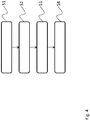
- the cooking vessel 321 as shown in Figure 3 is provided with three cooking vessel stirring devices 300, 308, 309. It is understood that any other number of cooking vessel stirring devices is possible.
- the cooking vessel stirring devices 300, 308, 309 are cooking vessel stirring devices as shown in Figure 2 . It is understood, that any other embodiment of a cooking vessel stirring device as shown in the present disclosure may be used.
- a controller in the inductive cooking hob 322 may modulate the magnetic field generated by the induction coil of the inductive cooking zone 323 accordingly.
- the inductive cooking hob 322 may also comprise respective controls that allow a user to control the operation of the cooking vessel stirring devices 300, 308, 309.
- the control interface may be a communication interface that may communicate with mobile devices, like e.g. a smartphone. Such a control interface may be e.g., a WiFi or Bluetooth interface.
- a user may then be provided with a respective application on the mobile device to control the cooking vessel stirring devices 300, 308, 309.
- Figure 4 shows a flow diagram of a method for stirring contents of a cooking vessel 321 in a cooking system 320 according to the present disclosure.
- the method comprises mechanically fixing S1 the cooking vessel stirring device 100, 200, 300, 308, 309 in the cooking vessel 321, generating S2 a magnetic field with a predefined frequency in the cooking zone of the cooking hob which carries the cooking vessel 321, harvesting S3 electrical energy 103, 203 from the generated magnetic field in the cooking vessel stirring device 100, 200, 300, 308, 309, and operating S4 the electric engine 104, 204 of the cooking vessel stirring device 100, 200, 300, 308, 309 based on the harvested electrical energy.
- the electrical energy 103, 203 may be harvested via an induction coil 210 coupled to a rectifier circuit 211 that outputs the electrical energy 103, 203.
- the electrical energy 103, 203 may be harvested from a magnetic field with a predetermined frequency.
- the method may also comprise controlling the electric engine 104, 204 of the cooking vessel stirring device 100, 200, 300, 308, 309 based on the harvested electrical energy 103, 203.
- controlling may comprise receiving control signals in the cooking vessel stirring device 100, 200, 300, 308, 309, and controlling the electric engine 104, 204 based on the control signals.
- Mechanically fixing may comprise fixing the cooking vessel stirring device 100, 200, 300, 308, 309 in the cooking vessel 321 with a suction cup.
- mechanically fixing may comprise fixing the cooking vessel stirring device 100, 200, 300, 308, 309 in the cooking vessel 321 with a bayonet coupling or a screw coupling or a snap-on element.
Landscapes
- Physics & Mathematics (AREA)
- Electromagnetism (AREA)
- Food-Manufacturing Devices (AREA)
Abstract
Description
- The disclosure relates to a cooking vessel, a cooking system, and a respective method.
- Although applicable to any cooking device, the present disclosure will mainly be described in conjunction with inductive cooking hobs.
- When cooking with induction stoves or hobs, solid materials in the cooking vessel usually sink to the bottom of the cooking vessel, if the solid materials are not mixed during cooking.
- However, some foods need to be mixed during cooking e.g., for preventing the foods from burning or for ensuring homogenous cooking and distribution of spices or the like. Usually the user that uses the cooking hob will manually stir the foods during the cooking process e.g., with a cooking spoon.
- Accordingly, there is a need for improving the cooking process for users.
- The above stated problem is solved by the features of the independent claims. It is understood, that independent claims of a claim category may be formed in analogy to the dependent claims of another claim category.
- Accordingly, it is provided:
A cooking vessel stirring device for stirring contents of a cooking vessel, comprising a mechanical fixation element configured to fix the cooking vessel stirring device in the cooking vessel, an inductive energy harvesting circuit configured to generate electrical energy from an external magnetic field, and an electric engine mechanically coupled to the mechanical fixation element and electrically coupled to the inductive energy harvesting circuit, wherein the electric engine is configured to operate based on electrical energy provided by the inductive energy harvesting circuit. - Further, it is provided:
A cooking system comprising a cooking vessel, a number i.e., one or more, of cooking vessel stirring device according to the present disclosure arranged in the cooking vessel, and an inductive cooking hob with at least one inductive cooking zone configured to accept the cooking vessel. - Further, it is provided:
A method for stirring contents of a cooking vessel in a cooking system according the present disclosure, the method comprising mechanically fixing the cooking vessel stirring device in the cooking vessel, generating a magnetic field with a predefined frequency in the cooking zone of the cooking hob which carries the cooking vessel, harvesting electrical energy from the generated magnetic field in the cooking vessel stirring device, and operating the electric engine of the cooking vessel stirring device based on the harvested electrical energy. - The present disclosure is based on the finding that present solutions for improving the cooking process, like e.g. mixers with integrated heating, usually limit the cook in the cooking process. Mixers for example usually comprise a limited capacity in the cooking vessel.
- The present disclosure therefore provides the possibility to use conventional cooking vessels, like pots, and add an automatic stirring to the cooking vessels.
- To this end, the present disclosure provides the cooking vessel stirring device, that may be inserted into a cooking vessel for automatic stirring of the contents of the cooking vessel.
- The cooking vessel stirring device to this end comprises the mechanical fixation element. With the mechanical fixation element, the cooking vessel stirring device may be fixed in the cooking vessel at a specific position. The cooking vessel stirring device may therefore be held in a specific place in the cooking vessel, especially but not necessarily on the bottom of the cooking vessel.
- Coupled to the mechanical fixation element an electric engine is provided. The electric engine is electrically coupled to an inductive energy harvesting circuit and is mechanically coupled to the mechanical fixation element.
- The cooking vessel stirring device may therefore be fixed on the bottom of a cooking vessel and may receive electrical energy from the inductive energy harvesting circuit. The electric engine may operate based on the electrical energy received from the inductive energy harvesting circuit.
- The cooking vessel stirring device may for example be used with a cooking system according to the present disclosure. Such a cooking system comprises an inductive cooking hob with at least one inductive cooking zone that generates a magnetic field to heat up a cooking vessel. In combination with such an inductive cooking hob, the cooking vessel stirring device is powered by the magnetic field generated by the inductive cooking hob for heating up the cooking vessel.
- During a cooking operation, the contents in a cooking vessel may therefore be stirred automatically and without limiting the user to a specific cooking device, like a mixer with included heating function.
- Further embodiments of the present disclosure are subject of the further subclaims and of the following description, referring to the drawings.
- In an embodiment, the inductive energy harvesting circuit may comprise an induction coil coupled to a rectifier circuit, wherein the rectifier circuit may be configured to output electrical energy.
- As explained above, the inductive energy harvesting circuit harvests electrical energy from a magnetic field. Using an induction coil together with a rectifier circuit allows easily harvesting electrical energy with a circuit of low complexity.
- In other embodiments, the inductive energy harvesting circuit only comprises an induction coil that outputs alternating voltage and current and directly drives the electrical engine. It is understood, that the term "directly" in this context also allows including any supporting circuitry that is required to drive the electric engine with the alternating voltage and current, like e.g. capacitors, resistors or the like. The term "directly" in this context does however, not encompass the use of active engine control elements, like a switches and the like.
- In another embodiment, the inductive energy harvesting circuit may be tuned to harvest electrical energy from a magnetic field with a predetermined frequency.
- The inductive energy harvesting circuit may be tuned to operate at specific frequencies. The inductive energy harvesting circuit may for example be tuned to operate at a frequency that is used by the inductive cooking hob of the cooking system to drive the induction coils in the cooking zones.
- The frequency that is used by the inductive cooking hob may be detected by an analog-to-digital conversion circuit in the inductive energy harvesting circuit. A controller in the inductive energy harvesting circuit may then determine the frequency and for example actively control switches in a the inductive energy harvesting circuit accordingly, such the amount of harvested energy is maximized.
- It is further understood, that in a cooking system with multiple cooking vessel stirring devices, the single cooking vessel stirring devices may be tuned to operate at different frequencies, i.e. the inductive energy harvesting circuits may be adapted respectively.
- For example, a first cooking vessel stirring device may be tuned to operate at 1 kHz, a second cooking vessel stirring device may be tuned to operate at 1,5 kHz, and so on.
- In case a direct supply of the electric engine, i.e. without active control elements, is used, the electric engine may rotate with a frequency that is directly proportional to the frequency of the magnetic field and the number of poles of the electric engine. The electric engine may in such embodiments for example be provided as asynchronous engine or motor.
- In an alternative embodiment, all cooking vessel stirring devices may be tuned to operate at the same frequency. However, controllers in the cooking vessel stirring devices may be configured to drive the respective electric engine at different speeds.
- In a further embodiment, the cooking vessel stirring device may comprise an engine controller coupled electrically between the inductive energy harvesting circuit and the electric engine. The engine controller may be configured to control the electric engine based on the electrical energy provided by the inductive energy harvesting circuit.
- The engine controller may be any device that is capable of controlling the electrical engine. Therefore, the engine controller may be adapted to the type of electric engine used. If for example, the electric engine is an asynchronous engine, the engine controller may be a kind of variable frequency drive (VFD) controller.
- In case that the electric engine is a constant current engine, the engine controller may comprise e.g. a simple switch or a voltage controller to provide the engine with a predetermined input voltage from the inductive energy harvesting circuit. If the engine is to run in two directions, the engine controller may comprise an H-bridge circuit.
- In another embodiment, the engine controller may comprise a control interface configured to receive control signals, and wherein the engine controller may be configured to control the electric engine based on the control signals.
- The control interface may be provided as wireless control interface. In an embodiment, the control interface is provided as a function in the engine controller that determines the frequency of the magnetic field that provides power to the inductive energy harvesting circuit. For example, a first frequency may be defined that indicates that the electric engine is not to run, a second frequency may indicated that the electric engine is to run. In an embodiment, two different frequencies may be defined to indicate in which direction the electric engine is to run.
- In another embodiment, the magnetic field created to heat up the cooking vessel may be modulated based on control information. The communication interface may be configured to demodulate the received signal to reconstruct the control information.
- In another embodiment, the control interface may comprise any type of wireless interface that allows transmitting the required information to the engine controller, such a wireless interface may comprise e.g., RFID or NFC type interfaces, Bluetooth interfaces or the like.
- In an embodiment, the mechanical fixation element may comprises a suction cup or suction pad configured to fix the cooking vessel stirring device.
- The suction cup provides a very flexible mechanical arrangement that serves for fixing the cooking vessel stirring device on different surfaces, especially on the bottom surface or the inner side of the wall of a cooking vessel.
- With a mechanical fixation element that comprises a suction cup, the cooking vessel stirring device may be used with any type of cooking vessel without the need to provide specific holding elements in the cooking vessel.
- In another embodiment, the mechanical fixation element comprises a bayonet coupling or a screw coupling or a snap-on element.
- In contrast to the suction cup fixation, the bayonet coupling, the screw coupling and the snap-on element may be used with cooking vessels that provide respective counterparts.
- While the bayonet coupling of the cooking vessel stirring device may comprise a rod-type element, the cooking vessel may comprise a respective recess for inserting the rod-type element. With a screw coupling, the cooking vessel stirring device may be provided with a screw, while the cooking vessel may be provided with respective threaded holes for inserting the screw. If a snap-on element is used with the cooking vessel stirring device, the cooking vessel may be equipped with respective counterparts for the snap-on element.
- With such mechanical fixation elements, the cooking vessel stirring device may be fixed strongly to the cooking vessel and may therefore provide high stirring forces.
- For a more complete understanding of the present disclosure and advantages thereof, reference is now made to the following description taken in conjunction with the accompanying drawings. The disclosure is explained in more detail below using exemplary embodiments which are specified in the schematic figures of the drawings, in which:
-
Figure 1 shows a block diagram of an embodiment of a cooking vessel stirring device according to the present disclosure; -
Figure 2 shows a block diagram of another embodiment of a cooking vessel stirring device according to the present disclosure; -
Figure 3 shows a block diagram of an embodiment of a cooking system according to the present disclosure; and -
Figure 4 shows a flow diagram of an embodiment of a method according to the present disclosure. - In the figures like reference signs denote like elements unless stated otherwise.
-
Figure 1 shows a block diagram of a cookingvessel stirring device 100. The cookingvessel stirring device 100 comprises amechanical fixation element 101, an inductiveenergy harvesting circuit 102, and anelectric engine 104. - The
mechanical fixation element 101 serves for fixing the cookingvessel stirring device 100 in the cooking vessel. Although not explicitly shown, it is understood, that themechanical fixation element 101 may be mechanically coupled to a static element of the cookingvessel stirring device 100, like e.g. a housing-part. - The inductive
energy harvesting circuit 102 generateselectrical energy 103 from an external magnetic field that may be provided to the cookingvessel stirring device 100 e.g., from an inductive cooking zone as shown inFig. 3 . It is however understood, that the source of the magnetic field may also be another source than an inductive cooking zone. For example, conventional cooking hobs or gas cooking hobs may be equipped with an additional magnetic field source. This allows using the cookingvessel stirring device 100 with any type of cooking hob. - The inductive
energy harvesting circuit 102 is electrically coupled to theelectric engine 104. Further, the static section of theelectric engine 104 is mechanically coupled to themechanical fixation element 101, e.g. via the above-mentioned housing part. - A rotor of the
electric engine 104 is coupled to another part of the housing e.g., to a rotating part of the housing. In embodiments, the rotating part of the housing and the rotor of theelectric engine 104 are the same part. In the cookingvessel stirring device 100stirring blades vessel stirring device 100 e.g. to the rotor of theelectric engine 104. - The
mechanical fixation element 101 may e.g. be provided as a suction cup that may be fixed to the bottom or the side walls of the cookingvessel stirring device 100. It is understood, that themechanical fixation element 101 may also comprise a bayonet coupling or a screw coupling or a snap-on element or any other mechanically releasable fixing mechanism with interlocking parts. - In an embodiment, the
mechanical fixation element 101 may comprise a fixation base for fixation on a surface and a rod that stands up and forms an internal stator for theelectric engine 104. The rod may comprise respective permanent magnets. The further elements of the cookingvessel stirring device 100 may then be provided in a housing that comprises a round recess and may be put on said rod. -
Figure 2 shows a block diagram of another cookingvessel stirring device 200. The cookingvessel stirring device 200 is based on the cookingvessel stirring device 100. Therefore, the cookingvessel stirring device 200 comprises amechanical fixation element 201, an inductiveenergy harvesting circuit 202, and anelectric engine 204. - The inductive
energy harvesting circuit 202 of the cookingvessel stirring device 200 comprises aninduction coil 210 coupled to arectifier circuit 211. In the inductiveenergy harvesting circuit 202, theinduction coil 210 is excited by an external magnetic field to output respective electrical energy. Therectifier circuit 211 receives the output provided by theinduction coil 210, rectifies the received electrical energy i.e., the voltage and current, for example with respective diodes, and outputs theelectrical energy 203 to anengine controller 212 that is coupled electrically between the inductiveenergy harvesting circuit 202 and theelectric engine 204. - The inductive
energy harvesting circuit 202 may be tuned to harvestelectrical energy 203 from a magnetic field with a predetermined frequency. To this end, theinduction coil 210 may be dimensioned accordingly and therectifier circuit 211 may comprise respective elements or a respective circuit may be provided tuned to said frequency. - The
engine controller 212 is configured to control theelectric engine 204 based on theelectrical energy 203 provided by the inductiveenergy harvesting circuit 202. - In the cooking
vessel stirring device 200, theengine controller 212 comprises acontrol interface 213. Thecontrol interface 213 may serve for providing control information wirelessly to theengine controller 212. - The
control interface 213 may for example be implemented by a demodulator that demodulates the control information in the signal provided from theinduction coil 210 to theengine controller 212. The source of the magnetic field may comprise a respective counterpart that modulates the control information into the magnetic field. The modulation may e.g. be a frequency modulation or a kind of PWM-based modulation or the like. In theengine controller 212 the control information may be used to control theelectric engine 204 accordingly. For example, the control information may indicate to theengine controller 212 that theelectric engine 204 is to be activated i.e., operated to run in a specific direction, or to be stopped. - It is understood, that the
engine controller 212 is optional. In an embodiment, theelectric engine 204 may be driven directly with the output of theinduction coil 210. Further, if theengine controller 212 is provided thecontrol interface 213 is optional. Without thecontrol interface 213 theengine controller 212 may be configured to directly operate theelectric engine 204 as soon as output is provided by theinduction coil 210. -
Figure 3 shows a block diagram of an embodiment of acooking system 320. Thecooking system 320 comprises acooking vessel 321 that is arranged on aninductive cooking zone 323 of an inductive cooking hob 322 (only schematically shown). - The
inductive cooking hob 322 may comprise any number of inductive cooking zones, although only onecooking zone 323 is shown inFigure 3 . Further, flexible cooking zones may be provided i.e., no specific location is defined for a cooking zone. Instead, a controller of theinductive cooking hob 322 may detect where on the surface of theinductive cooking hob 322 thecooking vessel 321 is placed and activate a respective coil or respective coils. - The
cooking vessel 321 as shown inFigure 3 is provided with three cookingvessel stirring devices vessel stirring devices Figure 2 . It is understood, that any other embodiment of a cooking vessel stirring device as shown in the present disclosure may be used. - If cooking
vessel stirring devices inductive cooking hob 322 may modulate the magnetic field generated by the induction coil of theinductive cooking zone 323 accordingly. Theinductive cooking hob 322 may also comprise respective controls that allow a user to control the operation of the cookingvessel stirring devices - A user may then be provided with a respective application on the mobile device to control the cooking
vessel stirring devices - For sake of clarity in the following description of the method based
Fig. 4 the reference signs used above in the description of apparatus basedFigs. 1 - 3 will be maintained. -
Figure 4 shows a flow diagram of a method for stirring contents of acooking vessel 321 in acooking system 320 according to the present disclosure. - The method comprises mechanically fixing S1 the cooking
vessel stirring device cooking vessel 321, generating S2 a magnetic field with a predefined frequency in the cooking zone of the cooking hob which carries thecooking vessel 321, harvesting S3electrical energy vessel stirring device electric engine vessel stirring device - The
electrical energy induction coil 210 coupled to arectifier circuit 211 that outputs theelectrical energy electrical energy - The method may also comprise controlling the
electric engine vessel stirring device electrical energy vessel stirring device electric engine - Mechanically fixing may comprise fixing the cooking
vessel stirring device cooking vessel 321 with a suction cup. As alternative, mechanically fixing may comprise fixing the cookingvessel stirring device cooking vessel 321 with a bayonet coupling or a screw coupling or a snap-on element. - Although specific embodiments have been illustrated and described herein, it will be appreciated by those of ordinary skill in the art that a variety of alternate and/or equivalent implementations exist. It should be appreciated that the exemplary embodiment or exemplary embodiments are only examples, and are not intended to limit the scope, applicability, or configuration in any way. Rather, the foregoing summary and detailed description will provide those skilled in the art with a convenient road map for implementing at least one exemplary embodiment, it being understood that various changes may be made in the function and arrangement of elements described in an exemplary embodiment without departing from the scope as set forth in the appended claims and their legal equivalents. Generally, this application is intended to cover any adaptations or variations of the specific embodiments discussed herein.
-
- 100, 200, 300, 308, 309
- cooking vessel stirring device
- 101, 201
- mechanical fixation element
- 102, 202
- inductive energy harvesting circuit
- 103, 203
- electrical energy
- 104, 204
- electric engine
- 105, 106, 205, 206
- stirring blade
- 210
- induction coil
- 211
- rectifier circuit
- 212
- engine controller
- 213
- control interface
- 320
- cooking system
- 321
- cooking vessel
- 322
- inductive cooking hob
- 323
- inductive cooking zone
- S1 - S4
- method steps
Claims (15)
- Cooking vessel stirring device (100, 200, 300, 308, 309) for stirring contents of a cooking vessel (321), comprising:a mechanical fixation element (101, 201) configured to fix the cooking vessel stirring device (100, 200, 300, 308, 309) in the cooking vessel (321);an inductive energy harvesting circuit (102, 202) configured to generate electrical energy (103, 203) from an external magnetic field; andan electric engine (104, 204) mechanically coupled to the mechanical fixation element (101, 201) and electrically coupled to the inductive energy harvesting circuit (102, 202), wherein the electric engine (104, 204) is configured to operate based on electrical energy (103, 203) provided by the inductive energy harvesting circuit (102, 202).
- Cooking vessel stirring device (100, 200, 300, 308, 309) according to claim 1, wherein the inductive energy harvesting circuit (102, 202) comprises an induction coil (210) coupled to a rectifier circuit (211), wherein the rectifier circuit (211) is configured to output electrical energy (103, 203).
- Cooking vessel stirring device (100, 200, 300, 308, 309) according to any one of the preceding claims, wherein the inductive energy harvesting circuit (102, 202) is tuned to harvest electrical energy (103, 203) from a magnetic field with a predetermined frequency.
- Cooking vessel stirring device (100, 200, 300, 308, 309) according to any one of the preceding claims, comprising an engine controller (212) coupled electrically between the inductive energy harvesting circuit (102, 202) and the electric engine (104, 204), wherein the engine controller (212) is configured to control the electric engine (104, 204) based on the electrical energy (103, 203) provided by the inductive energy harvesting circuit (102, 202).
- Cooking vessel stirring device (100, 200, 300, 308, 309) according to claim 4, wherein the engine controller (212) comprises a control interface (213) configured to receive control signals, and wherein the engine controller (212) is configured to control the electric engine (104, 204) based on the control signals.
- Cooking vessel stirring device (100, 200, 300, 308, 309) according to any one of the preceding claims, wherein the mechanical fixation element (101, 201) comprises a suction cup configured to fix the cooking vessel stirring device (100, 200, 300, 308, 309).
- Cooking vessel stirring device (100, 200, 300, 308, 309) according to any one of the preceding claims 1 to 5, wherein the mechanical fixation element (101, 201) comprises a bayonet coupling or a screw coupling or a snap-on element.
- Cooking system (320) comprising
a cooking vessel (321);
a number of cooking vessel stirring devices (100, 200, 300, 308, 309) according to any one of the preceding claims arranged in the cooking vessel (321); and
an inductive cooking hob (322) with at least one inductive cooking zone (323) configured to accept the cooking vessel (321). - Method for stirring contents of a cooking vessel (321) in a cooking system (320) according to claim 8, comprising:mechanically fixing (S1) the cooking vessel stirring device (100, 200, 300, 308, 309) in the cooking vessel (321);generating (S2) a magnetic field with a predefined frequency in the cooking zone of the cooking hob which carries the cooking vessel (321);harvesting (S3) electrical energy (103, 203) from the generated magnetic field in the cooking vessel stirring device (100, 200, 300, 308, 309); andoperating (S4) the electric engine (104, 204) of the cooking vessel stirring device (100, 200, 300, 308, 309) based on the harvested electrical energy (103, 203).
- Method according to claim 9, wherein the electrical energy (103, 203) is harvested via an induction coil (210) coupled to a rectifier circuit (211) that outputs the electrical energy (103, 203).
- Method according to any one of the preceding method-related claims, wherein electrical energy (103, 203) is harvested from a magnetic field with a predetermined frequency.
- Method according to any one of the preceding method-related claims, comprising controlling the electric engine (104, 204) of the cooking vessel stirring device (100, 200, 300, 308, 309) based on the harvested electrical energy (103, 203).
- Method according to any claim 12, wherein controlling comprises receiving control signals in the cooking vessel stirring device (100, 200, 300, 308, 309), and controlling the electric engine (104, 204) based on the control signals.
- Method according to any one of the preceding method-related claims, wherein mechanically fixing comprises fixing the cooking vessel stirring device (100, 200, 300, 308, 309) in the cooking vessel (321) with a suction cup.
- Method according to any one of the preceding method-related claims 9 to 13, wherein mechanically fixing comprises fixing the cooking vessel stirring device (100, 200, 300, 308, 309) in the cooking vessel (321) with a bayonet coupling or a screw coupling or a snap-on element.
Priority Applications (3)
| Application Number | Priority Date | Filing Date | Title |
|---|---|---|---|
| EP21168890.8A EP4075922A1 (en) | 2021-04-16 | 2021-04-16 | Cooking vessel, cooking system, and method |
| CN202180097103.2A CN117223391A (en) | 2021-04-16 | 2021-04-28 | Cooking container, cooking system and method |
| PCT/EP2021/061111 WO2022218556A1 (en) | 2021-04-16 | 2021-04-28 | Cooking vessel, cooking system, and method |
Applications Claiming Priority (1)
| Application Number | Priority Date | Filing Date | Title |
|---|---|---|---|
| EP21168890.8A EP4075922A1 (en) | 2021-04-16 | 2021-04-16 | Cooking vessel, cooking system, and method |
Publications (1)
| Publication Number | Publication Date |
|---|---|
| EP4075922A1 true EP4075922A1 (en) | 2022-10-19 |
Family
ID=75562644
Family Applications (1)
| Application Number | Title | Priority Date | Filing Date |
|---|---|---|---|
| EP21168890.8A Pending EP4075922A1 (en) | 2021-04-16 | 2021-04-16 | Cooking vessel, cooking system, and method |
Country Status (3)
| Country | Link |
|---|---|
| EP (1) | EP4075922A1 (en) |
| CN (1) | CN117223391A (en) |
| WO (1) | WO2022218556A1 (en) |
Citations (4)
| Publication number | Priority date | Publication date | Assignee | Title |
|---|---|---|---|---|
| US3761668A (en) * | 1972-03-01 | 1973-09-25 | Gen Electric | Small electrical apparatus powered by induction cooking appliances |
| EP0453634A2 (en) * | 1990-04-24 | 1991-10-30 | Lancet S.A. | Cooking device |
| JPH09115660A (en) * | 1995-10-18 | 1997-05-02 | Toshiba Corp | Induction heating cooker |
| WO2020128014A1 (en) * | 2018-12-21 | 2020-06-25 | BSH Hausgeräte GmbH | Induction energy transmission system |
-
2021
- 2021-04-16 EP EP21168890.8A patent/EP4075922A1/en active Pending
- 2021-04-28 CN CN202180097103.2A patent/CN117223391A/en active Pending
- 2021-04-28 WO PCT/EP2021/061111 patent/WO2022218556A1/en active Application Filing
Patent Citations (4)
| Publication number | Priority date | Publication date | Assignee | Title |
|---|---|---|---|---|
| US3761668A (en) * | 1972-03-01 | 1973-09-25 | Gen Electric | Small electrical apparatus powered by induction cooking appliances |
| EP0453634A2 (en) * | 1990-04-24 | 1991-10-30 | Lancet S.A. | Cooking device |
| JPH09115660A (en) * | 1995-10-18 | 1997-05-02 | Toshiba Corp | Induction heating cooker |
| WO2020128014A1 (en) * | 2018-12-21 | 2020-06-25 | BSH Hausgeräte GmbH | Induction energy transmission system |
Also Published As
| Publication number | Publication date |
|---|---|
| CN117223391A (en) | 2023-12-12 |
| WO2022218556A1 (en) | 2022-10-20 |
Similar Documents
| Publication | Publication Date | Title |
|---|---|---|
| JP6173623B2 (en) | Induction heating cooker and control method thereof | |
| US9610553B2 (en) | Beverage mixing system and method | |
| WO2013094174A1 (en) | Non-contact power supply apparatus and non-contact power transmission system | |
| JP6403808B2 (en) | Non-contact power transmission device and non-contact power transmission system | |
| US8288975B2 (en) | BLDC motor with a simulated tapped winding interface | |
| CN107276324B (en) | NFC antenna for communicating with a motor and methods of making and using the same | |
| CN102844954A (en) | System and method for regulating inductive power transmission | |
| EP2757658A1 (en) | Non-contact power feed device and non-contact power transmission device | |
| JP2006102055A (en) | Cordless power source apparatus | |
| EP3042542B1 (en) | An individual cookware control device for use with an induction heating cooker, and wireless cooking system having the same | |
| EP3869660A1 (en) | Wireless power transfer apparatus, wireless power reception apparatus, and system including the same | |
| CN109073230B (en) | Heating cooking system, induction heating cooker, and cooking device | |
| GB2565930A (en) | Noncontact power transmission apparatus, noncontact power transmission system, and induction heating cooking device | |
| JP2010049959A (en) | Induction heating cooker | |
| EP4075922A1 (en) | Cooking vessel, cooking system, and method | |
| JPH08315975A (en) | Induction heating cooker | |
| KR102438929B1 (en) | Modular cooking apparatus system and operating method for the same | |
| TR2021006687A2 (en) | Cooking vessel, cooking system, and method | |
| CN210575676U (en) | Wireless knob controller, knob and base | |
| JPH09238851A (en) | Cooking device | |
| JP2016007247A (en) | Agitating adapter | |
| JP4863920B2 (en) | Electromagnetic cooker system | |
| EP3869666A1 (en) | Wireless power transmission apparatus and method of operating the same | |
| US20170202059A1 (en) | Induction stirring apparatus for induction cooktops | |
| FR3113360A1 (en) | Kitchen utensil powered by induction hob |
Legal Events
| Date | Code | Title | Description |
|---|---|---|---|
| PUAI | Public reference made under article 153(3) epc to a published international application that has entered the european phase |
Free format text: ORIGINAL CODE: 0009012 |
|
| STAA | Information on the status of an ep patent application or granted ep patent |
Free format text: STATUS: THE APPLICATION HAS BEEN PUBLISHED |
|
| AK | Designated contracting states |
Kind code of ref document: A1 Designated state(s): AL AT BE BG CH CY CZ DE DK EE ES FI FR GB GR HR HU IE IS IT LI LT LU LV MC MK MT NL NO PL PT RO RS SE SI SK SM TR |
|
| STAA | Information on the status of an ep patent application or granted ep patent |
Free format text: STATUS: REQUEST FOR EXAMINATION WAS MADE |
|
| 17P | Request for examination filed |
Effective date: 20230417 |
|
| RBV | Designated contracting states (corrected) |
Designated state(s): AL AT BE BG CH CY CZ DE DK EE ES FI FR GB GR HR HU IE IS IT LI LT LU LV MC MK MT NL NO PL PT RO RS SE SI SK SM TR |
|
| GRAP | Despatch of communication of intention to grant a patent |
Free format text: ORIGINAL CODE: EPIDOSNIGR1 |
|
| STAA | Information on the status of an ep patent application or granted ep patent |
Free format text: STATUS: GRANT OF PATENT IS INTENDED |
|
| INTG | Intention to grant announced |
Effective date: 20230925 |