EP0453634A2 - Cooking device - Google Patents
Cooking device Download PDFInfo
- Publication number
- EP0453634A2 EP0453634A2 EP90121864A EP90121864A EP0453634A2 EP 0453634 A2 EP0453634 A2 EP 0453634A2 EP 90121864 A EP90121864 A EP 90121864A EP 90121864 A EP90121864 A EP 90121864A EP 0453634 A2 EP0453634 A2 EP 0453634A2
- Authority
- EP
- European Patent Office
- Prior art keywords
- cooking
- stirrer
- utensil
- heating
- cooking system
- Prior art date
- Legal status (The legal status is an assumption and is not a legal conclusion. Google has not performed a legal analysis and makes no representation as to the accuracy of the status listed.)
- Granted
Links
Images


Classifications
-
- H—ELECTRICITY
- H05—ELECTRIC TECHNIQUES NOT OTHERWISE PROVIDED FOR
- H05B—ELECTRIC HEATING; ELECTRIC LIGHT SOURCES NOT OTHERWISE PROVIDED FOR; CIRCUIT ARRANGEMENTS FOR ELECTRIC LIGHT SOURCES, IN GENERAL
- H05B6/00—Heating by electric, magnetic or electromagnetic fields
- H05B6/02—Induction heating
- H05B6/06—Control, e.g. of temperature, of power
- H05B6/062—Control, e.g. of temperature, of power for cooking plates or the like
-
- A—HUMAN NECESSITIES
- A47—FURNITURE; DOMESTIC ARTICLES OR APPLIANCES; COFFEE MILLS; SPICE MILLS; SUCTION CLEANERS IN GENERAL
- A47J—KITCHEN EQUIPMENT; COFFEE MILLS; SPICE MILLS; APPARATUS FOR MAKING BEVERAGES
- A47J27/00—Cooking-vessels
- A47J27/004—Cooking-vessels with integral electrical heating means
-
- A—HUMAN NECESSITIES
- A47—FURNITURE; DOMESTIC ARTICLES OR APPLIANCES; COFFEE MILLS; SPICE MILLS; SUCTION CLEANERS IN GENERAL
- A47J—KITCHEN EQUIPMENT; COFFEE MILLS; SPICE MILLS; APPARATUS FOR MAKING BEVERAGES
- A47J27/00—Cooking-vessels
- A47J27/14—Cooking-vessels for use in hotels, restaurants, or canteens
-
- A—HUMAN NECESSITIES
- A47—FURNITURE; DOMESTIC ARTICLES OR APPLIANCES; COFFEE MILLS; SPICE MILLS; SUCTION CLEANERS IN GENERAL
- A47J—KITCHEN EQUIPMENT; COFFEE MILLS; SPICE MILLS; APPARATUS FOR MAKING BEVERAGES
- A47J43/00—Implements for preparing or holding food, not provided for in other groups of this subclass
- A47J43/04—Machines for domestic use not covered elsewhere, e.g. for grinding, mixing, stirring, kneading, emulsifying, whipping or beating foodstuffs, e.g. power-driven
- A47J43/044—Machines for domestic use not covered elsewhere, e.g. for grinding, mixing, stirring, kneading, emulsifying, whipping or beating foodstuffs, e.g. power-driven with tools driven from the top side
-
- B—PERFORMING OPERATIONS; TRANSPORTING
- B01—PHYSICAL OR CHEMICAL PROCESSES OR APPARATUS IN GENERAL
- B01F—MIXING, e.g. DISSOLVING, EMULSIFYING OR DISPERSING
- B01F27/00—Mixers with rotary stirring devices in fixed receptacles; Kneaders
- B01F27/05—Stirrers
- B01F27/11—Stirrers characterised by the configuration of the stirrers
- B01F27/114—Helically shaped stirrers, i.e. stirrers comprising a helically shaped band or helically shaped band sections
- B01F27/1142—Helically shaped stirrers, i.e. stirrers comprising a helically shaped band or helically shaped band sections of the corkscrew type
-
- B—PERFORMING OPERATIONS; TRANSPORTING
- B01—PHYSICAL OR CHEMICAL PROCESSES OR APPARATUS IN GENERAL
- B01F—MIXING, e.g. DISSOLVING, EMULSIFYING OR DISPERSING
- B01F27/00—Mixers with rotary stirring devices in fixed receptacles; Kneaders
- B01F27/23—Mixers with rotary stirring devices in fixed receptacles; Kneaders characterised by the orientation or disposition of the rotor axis
- B01F27/231—Mixers with rotary stirring devices in fixed receptacles; Kneaders characterised by the orientation or disposition of the rotor axis with a variable orientation during mixing operation, e.g. with tiltable rotor axis
- B01F27/2311—Mixers with rotary stirring devices in fixed receptacles; Kneaders characterised by the orientation or disposition of the rotor axis with a variable orientation during mixing operation, e.g. with tiltable rotor axis the orientation of the rotating shaft being adjustable in the interior of the receptacle, e.g. by tilting the stirrer shaft during the mixing
-
- B—PERFORMING OPERATIONS; TRANSPORTING
- B01—PHYSICAL OR CHEMICAL PROCESSES OR APPARATUS IN GENERAL
- B01F—MIXING, e.g. DISSOLVING, EMULSIFYING OR DISPERSING
- B01F31/00—Mixers with shaking, oscillating, or vibrating mechanisms
- B01F31/42—Mixers with shaking, oscillating, or vibrating mechanisms with pendulum stirrers, i.e. with stirrers suspended so as to oscillate about fixed points or axes
-
- B—PERFORMING OPERATIONS; TRANSPORTING
- B01—PHYSICAL OR CHEMICAL PROCESSES OR APPARATUS IN GENERAL
- B01F—MIXING, e.g. DISSOLVING, EMULSIFYING OR DISPERSING
- B01F31/00—Mixers with shaking, oscillating, or vibrating mechanisms
- B01F31/44—Mixers with shaking, oscillating, or vibrating mechanisms with stirrers performing an oscillatory, vibratory or shaking movement
- B01F31/443—Mixers with shaking, oscillating, or vibrating mechanisms with stirrers performing an oscillatory, vibratory or shaking movement performing a superposed additional movement other than oscillation, vibration or shaking
-
- B—PERFORMING OPERATIONS; TRANSPORTING
- B01—PHYSICAL OR CHEMICAL PROCESSES OR APPARATUS IN GENERAL
- B01F—MIXING, e.g. DISSOLVING, EMULSIFYING OR DISPERSING
- B01F35/00—Accessories for mixers; Auxiliary operations or auxiliary devices; Parts or details of general application
- B01F35/40—Mounting or supporting mixing devices or receptacles; Clamping or holding arrangements therefor
- B01F35/41—Mounting or supporting stirrer shafts or stirrer units on receptacles
- B01F35/412—Mounting or supporting stirrer shafts or stirrer units on receptacles by supporting both extremities of the shaft
- B01F35/4121—Mounting or supporting stirrer shafts or stirrer units on receptacles by supporting both extremities of the shaft at the top and at the bottom of the receptacle, e.g. for performing a conical orbital movement about a vertical axis
-
- F—MECHANICAL ENGINEERING; LIGHTING; HEATING; WEAPONS; BLASTING
- F24—HEATING; RANGES; VENTILATING
- F24B—DOMESTIC STOVES OR RANGES FOR SOLID FUELS; IMPLEMENTS FOR USE IN CONNECTION WITH STOVES OR RANGES
- F24B7/00—Stoves, ranges or flue-gas ducts, with additional provisions for convection heating
-
- H—ELECTRICITY
- H05—ELECTRIC TECHNIQUES NOT OTHERWISE PROVIDED FOR
- H05B—ELECTRIC HEATING; ELECTRIC LIGHT SOURCES NOT OTHERWISE PROVIDED FOR; CIRCUIT ARRANGEMENTS FOR ELECTRIC LIGHT SOURCES, IN GENERAL
- H05B6/00—Heating by electric, magnetic or electromagnetic fields
- H05B6/02—Induction heating
- H05B6/10—Induction heating apparatus, other than furnaces, for specific applications
- H05B6/12—Cooking devices
- H05B6/1209—Cooking devices induction cooking plates or the like and devices to be used in combination with them
- H05B6/1236—Cooking devices induction cooking plates or the like and devices to be used in combination with them adapted to induce current in a coil to supply power to a device and electrical heating devices powered in this way
-
- Y—GENERAL TAGGING OF NEW TECHNOLOGICAL DEVELOPMENTS; GENERAL TAGGING OF CROSS-SECTIONAL TECHNOLOGIES SPANNING OVER SEVERAL SECTIONS OF THE IPC; TECHNICAL SUBJECTS COVERED BY FORMER USPC CROSS-REFERENCE ART COLLECTIONS [XRACs] AND DIGESTS
- Y02—TECHNOLOGIES OR APPLICATIONS FOR MITIGATION OR ADAPTATION AGAINST CLIMATE CHANGE
- Y02B—CLIMATE CHANGE MITIGATION TECHNOLOGIES RELATED TO BUILDINGS, e.g. HOUSING, HOUSE APPLIANCES OR RELATED END-USER APPLICATIONS
- Y02B40/00—Technologies aiming at improving the efficiency of home appliances, e.g. induction cooking or efficient technologies for refrigerators, freezers or dish washers
Definitions
- the present invention relates to domestic food cooking apparatus and systems generally.
- U.S. Patent 3,635,147 describes a combination cooking-stirring vessel in which two sets of blades are rotated continuously by means of a motor drive applied to the rim of a generally round bowl, as food is heated. One set of blades rotates along the bottom of the bowl except at the center bottom region.
- U.S. Patent 1,790,115 describes apparatus for treating food products comprising a plurality of rotating blades and a curved bottom surface.
- U.S. Patent 4,693,610 describes an electrical household appliance for culinary purposes including apparatus for stirring and heating the contents of a bowl. This apparatus provides continuous rotation of a stirrer adjacent the bottom of a flat bottomed bowl.
- U.S. Patent 4,649,810 describes microcomputer-controlled, integrated cooking apparatus for automatically preparing culinary dishes.
- the apparatus includes a memory for storing one or more recipe programs.
- the recipe program specifies schedules for dispensing the ingredients from a compartmentalized carousel into a flat bottomed cooking vessel, for heating the vessel and for continuously stirring the contents of the vessel.
- U.S. Patent 1,491,991 describes a beverage mixer and heater which provides stirring of the contents of a container having an electric heating element incorporated in its construction.
- U.S. Patent 4,073,225 describes, on an industrial scale, a continuously operable meatball cooker employing a trough which is engaged by helical vanes.
- U.S. Patent 3,407,872 employs a trough-like tank having a reciprocating paddle for circulating a heating or cooling fluid.
- Italian patent 567138 granted October 1, 1957, describes a mechanical agitator including first and second series connected mutually angled shafts, which are driven by a motor.
- the second shaft includes a fixed termination end which engages the inner surface of a container.
- U.S. Patent 4,629,843 describes induction cooking apparatus having a ferrite coil support and includes monitoring and control apparatus for preventing heating of the ferrite coil support above its Curie temperature.
- U.S. Patent 4,467,162 describes an arrangement for an induction heating process employing a shielding plate member of non-magnetizable metallic material disposed in a space between a heating coil and a bottom plate.
- U.S. Patent 3,761,668 describes a cooking system wherein small electrical appliances are powered by an induction cooking device.
- U.S. Patent 4,817,510 illustrates cooking apparatus wherein the temperature of cooked food is automatically controlled and varied during a cooking cycle.
- U.S. Patent 4,885,447 describes a system for induction heating of the electric plates of a cooker and employs an inverter bridge of MOS technology to provide a pulsating current.
- U.S. Patent 4,736,082 describes electromagnetic induction heating apparatus capable of preventing undesirable states of cooking utensils or vessels.
- U.S. Patent 4,549,056 describes electromagnetic induction heating apparatus capable of heating nonmagnetic cooking vessels and employs an AC field having a frequency of at least 50 KHz and preferably about 100 KHz, for heating non-magnetic materials such as aluminum. For magnetic materials, such as iron, a separate switching circuit and a separate coil provide an AC field having a significantly lower operating frequency.
- U.S. Patent 4,749,836 describes electromagnetic induction cooking apparatus capable of providing a substantially constant input power, which includes features similar to those described above in connection with the apparatus of U.S. Patent 4,549,056.
- U.S. Patent 4,792,652 describes an electric induction cooking appliance with reduced harmonic emission which employs a plurality of coils wound in opposite senses.
- U.S. Patent 4,453,067 describes an induction heating coil having non-uniformly spaced turns.
- U.S. Patent 3,814,888 describes a solid state induction cooking appliance operating at ultrasonic frequencies.
- the present invention seeks to provide improved domestic food cooking apparatus as well as integrated, modular versatile domestic cooking systems for quick cooking of most foods in the kitchen.
- cooking will be used throughout to refer generally to the application of heat to foodstuffs in a domestic context and includes, inter alia, heating liquids of various viscosities, and dry roasting of bulk foodstuffs, such as nuts, beans and seeds.
- the cooking center of the present invention may comprise a compact unit which can operate interchangeably with a wide variety of cooking utensils.
- the cooking center is characterized in that it provides fast and uniform cooking at high energy efficiency.
- the cooking center of the present invention is easy to operate and may provide controlled cooking and even stirring of foods.
- a domestic cooking system useful for heating utensils having a bottom surface formed of a metal having low electrical resistance including electromagnetic induction apparatus including an induction coil having more than 80 turns and preferably more than 100 turns.
- a domestic cooking system useful for heating a utensil having a bottom surface formed of a metal having low electrical resistance
- the system comprising electromagnetic induction apparatus including an induction coil receiving an AC electrical input at a frequency less than 50 KHz and preferably less than 30 KHz.
- a domestic cooking system useful for heating a utensil having a bottom surface formed of a metal having low electrical resistance, the system comprising electromagnetic induction apparatus including an induction coil having a voltage of less than 4000 Volts thereacross during operation.
- a domestic cooking system useful for heating utensils having a bottom surface formed of a metal having low electrical resistance and comprising electromagnetic induction apparatus including induction producing apparatus producing inductance of at least 1000 microHenry and preferably in excess of 2000 microHenry.
- a domestic cooking system including a base defining at least one cooking location, electromagnetic induction apparatus for heating a food at the cooking location and apparatus for automatic stirring of the food at the cooking location.
- a domestic cooking system comprising electromagnetic induction apparatus for heating a food at the cooking location by providing magnetic flux at the cooking location and apparatus for providing electric field shielding at least between the electromagnetic induction apparatus and the cooking location.
- the apparatus for providing electric field shielding is operative to surround the electromagnetic induction apparatus and to provide electromagnetic shielding of the electromagnetic induction apparatus, while permitting the substantially unimpeded passage of magnetic flux across the electromagnetic shielding apparatus to the cooking location.
- a domestic cooking system useful for heating utensils having a bottom surface formed of a metal having low electrical resistance
- the system including electromagnetic induction apparatus for heating a food at a cooking location, the electromagnetic induction apparatus operating in a non-resonant mode.
- the electromagnetic induction apparatus comprises an induction coil and high frequency switching apparatus and apparatus for providing negative feedback to the high frequency switching apparatus.
- a domestic cooking system useful for heating utensils of a first type, having a bottom surface having high electrical resistance, and of a second type, having a bottom surface having low electrical resistance
- the system including: electromagnetic induction apparatus including an induction coil; automatic control apparatus for governing the operation of the electromagnetic induction apparatus and being operable in first and second modes, the first mode being suitable for heating utensils of the first type and employing a first number of turns of the induction coil and the second mode being suitable for heating utensils of the second type and employing a second number of turns of the induction coil, larger than the first number of turns; and apparatus for supplying an AC electrical power input to the induction coil generally at the same frequency during operation in both the first and second modes.
- a domestic cooking system comprising: a base defining at least one cooking location and comprising electromagnetic induction apparatus including: an induction coil disposed generally in at least one plane and operative to generate electromagnetic flux; and at least one magnetic field conductor disposed in a plane extending generally non-parallel to the at least one plane so as to direct electromagnetic flux generated by the induction coil to the at least one cooking location.
- the magnetic field conductor comprises a ferromagnetic foil which is disposed generally perpendicular to the at least one plane and has a ratio of width in the direction generally perpendicular to the at least one plane relative to thickness of at least 10 and more preferably of at least 200.
- the ferromagnetic foil comprises a plurality of groups of generally radially extending foils, individual ones of said plurality of groups being electrically insulated from each other.
- the magnetic field conductor comprises a ferromagnetic wire wound in a generally toroidal arrangement to define a plurality of loops, each of which is disposed in a plane generally perpendicular to the at least one plane.
- the magnetic field conductor includes portions which extend generally radially, comprises amorphous metal and has a thickness of less than 0.3 mm and preferably between 0.05 and 0.10 mm.
- the cooking system also comprises at least one cooking utensil defining a food heating surface and being operative to be heated by the electromagnetic flux at the cooking location, and the magnetic field conductor is disposed on the opposite side of the induction coil from the utensil.
- the system also includes automatically operative stirring apparatus and/or apparatus for sensing the temperature of a cooking utensil at a cooking location.
- the apparatus for sensing temperature may include apparatus for obtaining temperature information relating to a utensil from variations in the current passing through the induction coil.
- Apparatus may be provided for controlling the supply of heat to a utensil in accordance with the temperature of the utensil and may include apparatus for supplying heat until the temperature of the utensil exceeds the indicated desired temperature by a first threshold and thereafter supplying heat to maintain the difference between the temperature of the utensil and the indicated desired temperature within a second threshold.
- the apparatus for controlling may also comprise timing apparatus used to control the heating apparatus.
- the cooking utensil preferably includes a curved cooking surface having a generally circular cross sectional configuration and the stirring apparatus preferably includes: at least one stirrer arranged about a stirrer rotation axis and defining an attachment end and a termination end; apparatus for rotating the stirrer about the stirrer rotation axis; and apparatus for reciprocally rotating the stirrer about a reciprocal motion axis perpendicular to the stirrer rotation axis such that the termination end moves along the curved cooking surface.
- stirring apparatus for use with a utensil having a curved cooking surface having a generally circular cross sectional configuration, stirring apparatus comprising: at least one stirrer arranged about a stirrer rotation axis and defining an attachment end and a termination end; apparatus for rotating the at least one stirrer about the stirrer rotation axis; and apparatus for reciprocally rotating the at least one stirrer about a reciprocal motion axis perpendicular to the stirrer rotation axis such that the termination end moves along the curved cooking surface.
- the stirrer preferably has a generally screw-type configuration.
- the stirring drive apparatus preferably includes quick coupling apparatus for automatically coupling the stirrer drive apparatus to the stirrer.
- the stirring drive apparatus preferably provides first and second rotary drive outputs.
- the stirring apparatus preferably includes a utensil contacting member mounted onto the termination end of the stirrer and preferably is selectably orientable with respect thereto so as to correspond to the configuration of the utensil surface when in engagement therewith.
- stirring apparatus including: a stirrer having an attachment end and a termination end; apparatus for mounting the stirrer at the attachment end and driving the stirrer in motion in operative association with a utensil defining a utensil surface; and a utensil contacting member mounted onto the termination end of the stirrer and being selectably orientable with respect thereto so as to correspond to the configuration of the utensil surface when in engagement therewith.
- a cooking temperature sensor for use with a domestic cooking system including an induction heating apparatus including an induction coil and apparatus for measuring temperature by sensing variations in the current flow passing through the induction coil.
- a cooking utensil formed of a metal and defining a curved cooking surface and a heat transfer member, formed of a metal and having a generally flat bottom surface and a curved top surface engaging the underside of the curved cooking surface.
- the cooking utensil is formed of a metal surface having a high electrical resistance and the heat transfer member is formed of a metal having a low electrical resistance.
- both elements may be formed of the same metal.
- a cooking system including the above described cooking utensil and including apparatus for providing heating of the flat bottom surface thereof.
- the apparatus for providing heating may include a conventional electrical resistance heat source or alternatively an inductive heat source.
- Stirring apparatus of the type described hereinabove may be employed with the cooking utensil and the cooking system.
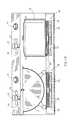
- Figs. 1A and 1B illustrate a cooking system constructed and operative in accordance with a preferred embodiment of the present invention and comprising a cooking center 10, including a back portion 12 and a base portion 14, defining a plurality of cooking locations 16, each arranged for operative association with a cooking utensil 18.
- a cooking center 10 including a back portion 12 and a base portion 14, defining a plurality of cooking locations 16, each arranged for operative association with a cooking utensil 18.
- the top surface of base portion 14 is formed of ceramic glass.
- the back portion 12 and the base portion 14 comprise various controls for each of the cooking locations 16, such as on-off, temperature and timing controls which may be embodied, for example, in a switch 19 with associated indicator light, a keyboard 20 and a dial 21.
- a status display 22, such as an LCD display, may also be provided.
- Also mounted on back portion 12 is a coupler 23 of a stirrer drive assembly, which is not seen in Figs. 1A - 1B, insofar as it is located at the interior of back portion 12.
- the base portion 14 typically defines four cooking locations. Each cooking location is typically provided with induction heating apparatus 25, which is not seen in Fig. 1A inasmuch as it is located within base 14.
- Fig. 1B which represents a section taken along the lines B - B in Fig. 1A
- cooking utensils formed of high resistance electrically conductive materials such as iron and stainless steel, and of low resistance electrically conductive materials, such as aluminum
- high resistance refers to materials having an electrical resistance within the general range extending from 0.05 ohm mm2/meter and higher, and preferably at least 0.1 ohm mm2/meter and including iron at 0.1 ohm mm2/meter and stainless steel, typically at 0.72 ohm mm2/meter.
- low resistance refers to materials having an electrical resistance within the general range below 0.05 ohm mm2/meter and preferably below 0.03 ohm mm2/meter and including aluminum at 0.0285 ohm mm2/meter and copper at 0.0175 ohm mm2/meter.
- a preferred embodiment of the induction heating apparatus 25 is illustrated in Fig. 6 and comprises an induction coil 26 comprising an electrical conductor which carries a current flow and is typically, but not necessarily, in the form of one or more coils, which lie in a single plane or alternatively in a plurality of generally parallel planes.
- Preferably associated with induction coil 26 and lying thereover and thereunder are layers of electrical insulation 28, which may be continuous or alternatively apertured, the apertures being configured and arranged as illustrated in Fig. 6, in order to provide an air flow path therepast, which may be useful when a ventilator (not shown) is provided in base portion 14.
- a magnetic field conductor assembly 30 Disposed under coil 26 is a magnetic field conductor assembly 30, various embodiments of which are illustrated in Figs. 7A - 7H.
- shielding apparatus 29 is disposed between induction coil 26 and cooking location 16 for providing electric field shielding therebetween without appreciably reducing the magnetic flux provided to the cooking location and without being itself heated to an unacceptable degree.
- apparatus 29 is operative to surround the induction heating apparatus and to provide electromagnetic shielding thereof, while permitting the substantially unimpeded passage of magnetic flux thereacross to the cooking location.
- the shielding apparatus 29 is formed of expanded stainless steel mesh.
- the apparatus 29 is formed of a woven or non-woven fabric including conductive fibers, such as carbon or metal fibers. Alternatively non-conductive fibers which are coated with a conductive coating may be employed.
- the coil 26 has an inner diameter of 40 mm, an outer diameter of 170 mm and a thickness of 5.2 mm.
- the coil has 120 turns and is formed of Litz wire, which is formed of 96 individually lacquered filaments, each of 0.13 mm diameter.
- a voltage of about 2000 volts AC is provided across coil 26 at an operative frequency of 22 KHz, providing, together with magnetic field conductor assembly 30, an inductance of about 3400 microHenry.
- the magnetic field conductor assembly 30, in accordance with a preferred embodiment of the invention, comprises an array of foils of a magnetic field conductive material, which are arranged to lie non-parallel and preferably generally perpendicularly to the plane or planes of the induction coil 26, so as to minimize the generation of eddy currents in the foils.
- the magnetic field conductors are formed of a high permeability material, such as an amorphous metal, and are typically each of thickness 0.025 mm.
- a high permeability material such as an amorphous metal
- Some preferred materials are Ultraperm 10, Permenorm (5000 H2 and 5000Z) and Vitrovac 4040, all of which are commercially available from Vacuumschmelze of Human, West Germany.
- a plurality of separate foils 32 are arranged to define radially extending sub-assemblies 36, which extend radially outward from the center of the assembly.
- the foils are typically retained in position by an insulative retaining ring 38, which may be provided at any suitable radial distance from the center of the assembly.
- each of foils 32 has a ratio of width in the direction generally perpendicular to the plane of the induction coil 26 relative to thickness in the plane of the induction coil of at least about 10 and preferably at least about 200.
- a preferable ratio is 600.
- each adjacent two sub-assemblies 36 are in fact defined by a single plurality of foils, which is bent adjacent the center of the assembly, as indicated at reference numeral 40.
- all of the sub-assemblies 36 are together defined by a single plurality of foils which extends intermittently both radially and circumferentially.
- one or a plurality of foils is arranged in a continuous undulating generally parallel array 41 having an overall generally square configuration.
- an undulating array 43 has an overall generally circular configuration, underlying coil 26.
- Figs. 7F and 7G an array of separate parallel foils or groups of foils is provided.
- the overall configuration of the array 45 is square
- the overall configuration of the array 47 is circular and conforms to the configuration of coil 26.
- the magnetic field conductor assembly 30 may comprise a ferromagnetic wire 48 wound in a generally toroidal arrangement to define a plurality of loops 49, each of which is disposed generally in a plane generally perpendicular to the plane of coil 26.
- the inductively heated cooking utensil need not necessarily have a flat bottom surface or a flat food cooking surface.
- the magnetic flux produced by induction coil 26 in response to passage of suitable current therethrough is spatially defined by the utensil 18 and by magnetic field conductor assembly 30.
- the use of thin foils 32 or loops extending generally non-parallel and preferably generally perpendicularly to the plane of the induction coil 26 instead of a thicker body of ferromagnetic material lowers the heating of the induction heating apparatus 25 as compared with the heating which would occur in a relatively thicker body of ferromagnetic material, such as ferrite, particularly if oriented parallel to the plane of the coil, thus increasing efficiency and inductance.
- foils 32 or wire 48 are formed of a material, such as amorphous metal, which has a relatively high Curie temperature and high permeability, especially at the operating frequency of induction heating apparatus 25, typically 22 KHz.
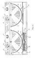
- Fig. 1C illustrates a system which is generally similar to that of Fig. 1B, except as described hereinbelow.
- the cooking utensil 13 is formed of a metal and defines a curved cooking surface 15.
- the cooking utensil 13 is formed to have a metal surface having a high electrical resistance and the heat transfer member 17 is formed of a metal having a low electrical resistance.
- This structure is particularly suitable for use with induction heating apparatus, such as that illustrated at reference number 25 in Fig. 1C.
- both elements 13 and 17 may be formed of the same metal.
- This alternative arrangement is suitable for use with a conventional resistance heating element, indicated by reference numeral 24. If a conventional resistance heating element is employed, the utensil may be formed of any suitable material, which need not necessarily be metal.
- Induction heating apparatus 25 is generally similar to that shown in Fig. 1B and described hereinabove. It may, however, be modified as will now be described. These modifications may also be employed where suitable in the various other embodiments of the invention described in the specification.
- Vibration absorbing apparatus 27 is preferably provided between the induction heating apparatus 25 and both the top and bottom surfaces of the base portion 14. Additionally, the top surface of the base portion 14 above each cooking location may be vibrationally decoupled from the remainder of the top surface of the base portion.
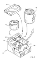
- Fig. 2 illustrates the modularity and flexibility of the cooking system of the present invention, wherein a single cooking location may alternatively accommodate a plurality of different utensils having different configurations, including, for example, both flat and curved bottom surfaces.
- utensils having bottom surfaces of either high or low electrical resistance, such as copper and aluminum may be used with the present invention.
- the utensils usable with the present invention include both special purpose utensils including stirring apparatus as well as entirely conventional cooking utensils, such as those seen in Fig. 2.
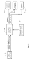
- Control apparatus employed in the cooking center is illustrated in Fig. 3 and includes user interface apparatus 50, typically incorporating switch 19, keyboard 20 and dial 21 (Fig. 1A), which provide control inputs relating to desired cooking time and desired temperature to control circuitry 52.
- Control circuitry 52 also receives a temperature input from temperature sensing apparatus 54 and provides a trigger output to induction heating assembly 56, a stirring control output to a stirring assembly 58, described hereinbelow, and a display output to a display 60, such as display 22 (Fig. 1).
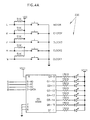
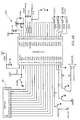
- a detailed schematic illustration of the control circuitry appears in Figs. 4A, 4B, 4C, 4D, 4E and 4F, it being noted that the user interfaces 50, cooking temperature sensors 54 and induction heating assembly 56 for only one cooking location are shown.
- the induction heating assembly 56 includes an induction coil 26 which is powered by switching power and control circuitry which provides a train of AC pulses having a frequency of about 22 KHz.
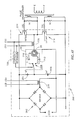
- the control circuitry illustrated in Figs. 4A - 4F, includes a power circuit 200, typically receiving a 220 Volt 50 cycle, electric mains input.
- the power circuit 200 comprises a bridge rectifier 202 and a pair of capacitors 204 and 206 providing voltage rectification.
- the junction of capacitors 204 and 206 is coupled via a high voltage relay 208 to one of two capacitors 210 or 212, which are in turn connected to the outer turn and the intermediate turn of induction coil 26.
- Relay 208 is operative to adapt the induction producing apparatus of the present invention for use with cooking utensils whose bottom surfaces have either high or low electrical resistance.
- the relay 208 connects the junction of capacitors 204 and 206 to an intermediate turn of induction coil 26, via capacitor 212.
- the relay 208 connects the junction of capacitors 204 and 206 to the outermost turn of induction coil 26 via capacitor 210.
- the interior turn of the induction coil 26 is coupled via sampling apparatus 220 to the junction of two series connected transistor switches 214 and 216, which are operative to provide a high frequency driving voltage across the induction coil 26 and either of capacitors 210 and 212.
- First sampling apparatus 218 samples the mains current, while second sampling apparatus 220 samples the peak current of transistor switches 214 and 216.
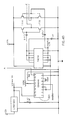
- the sampled information from apparatus 218 passes through circuitry 221 to a voltage controlled oscillator 224 which increases its output frequency as the sensed mains current increases.
- the sampled information from apparatus 220 is processed by a current detector 226 and is used to select the switching condition of relay 208. It is appreciated that apparatus 220 is operative to determine whether a utensil being heated by the induction heating apparatus of the present invention has a bottom surface with a high or low electrical resistance. In this way, the apparatus of the present invention is able to distinguish between, for example, utensils having stainless steel and aluminum bottoms and to be operative to safely and efficiently heat both types of utensils.
- relay 208 may be eliminated and the apparatus of the present invention may be designed to operate only with utensils having either high or low electrical resistance bottom surfaces.
- the sampled information from apparatus 220 is also supplied to circuitry 228 and is employed for protecting circuit elements.
- Circuitry 230 (Figs. 4A and 4B) provides timing, induction heating control, motor control and display functions.
- circuitry of Fig. 4C includes temperature sensors 54 which measure temperature by sensing the current flow passing through induction coil 26. Variations in the current flow provide indications of variations in temperature.
- Fig. 5 is a generalized flow chart illustrating the operation of the circuitry of Figs. 4A - 4F.
- the system determines if a utensil located at the cooking location has a bottom surface having high or low electrical resistance and adapts the operation of the circuitry of Figs. 4A - 4F, such as by means of relay 208, accordingly.
- the system is adapted for use only for utensils whose bottom surface has either a high or low electrical resistance, the system will operate only in the presence of the appropriate type of utensil.
- the system will periodically check to ensure that the utensil having an indicated resistance has remained at the cooking location, in order to prevent damage to the induction heating system or inefficient operation thereof.
- the system checks the desired temperature indicated by dial 21 and compares it with the temperature indicated by the temperature sensing apparatus.
- the induction heating assembly is operated as appropriate.
- the induction heating apparatus when the measured temperature is less than the predetermined temperature, instead of step 2, the induction heating apparatus may be operated continuously until a weighted temperature is reached, the weighted temperature being greater than the predetermined temperature, typically by a factor of about 1.2 times the difference between the measured temperature and the predetermined temperature. Once the measured temperature reaches the weighted temperature, the induction heating apparatus is operated according to step 2.
- the system operates to monitor the remaining desired cooking time and the ON status of switch 19. It provides for operation of the stirring device throughout cooking or as desired by the user. Upon termination of the desired cooking time, the induction heating apparatus is turned off and the stirring is typically continued for a given period and then terminated. Visual and/or auditory notification of completed cooking may be provided to the user.
- FIGs. 8 - 15 illustrate stirring apparatus constructed and operative in accordance with a preferred embodiment of the present invention.
- the stirring apparatus including a stirring assembly, indicated generally by reference numeral 60, is illustrated most clearly in Fig. 8.
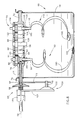
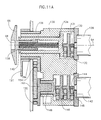
- Stirring assembly 60 is arranged for removable and automatic driving engagement with stirring drive apparatus, which is illustrated in Figs. 11A and 11B, via coupling apparatus, indicated generally by reference numeral 62.
- the coupling apparatus includes a first engagement portion 120, which is described in detail in Figs. 9A and 9B and which undergoes reciprocating rotation about an axis 64 and a second engagement portion 66 having a polygonal engagement recess 68. Second engagement portion 66 and recess 68 are arranged symmetrically with respect to axis 64 for rotation thereabout.
- the stirring assembly 60 comprises an axle portion 70 including a housing 72 and an internal drive shaft 74.
- Housing 72 is formed with a perpendicularly extending arm 73, which terminates adjacent a protrusion 75, extending perpendicularly to arm 73.
- Internal drive shaft 74 is formed at one end thereof with a polygonal engagement protrusion 76 which is configured to mate with recess 68. At an opposite end thereof, drive shaft 74 is provided with a conical gear 78. Conical gear 78 drivingly engages a corresponding conical gear 80 which is fixedly associated with a first stirrer drive axle 82.
- First stirrer drive axle 82 is seated within housing 72 and is provided with a polygonal bore 84 extending therethrough for receiving the shaft 86 of a stirrer 90.
- First stirrer drive axle 82 is also provided with a drive gear 92, which drivingly engages a first intermediate gear 94 on a first intermediate axle 96.
- Intermediate gear 94 drivingly engages a driving gear 98 which is mounted on an axle 100, which optionally can serve as a stirrer drive axle, in which case it is formed with an appropriate bore.
- Driving gear 98 drivingly engages a second intermediate gear 102 on a second intermediate axle 104.
- Intermediate gear 102 drivingly engages a driving gear 106 which is mounted on a second stirrer drive axle 108, which along with gears 94, 98 and 102 and axles 96, 100 and 104 is seated within housing 72 and which is provided with a polygonal bore 109, extending therethrough, for receiving the shaft 110 of a stirrer 112.
- stirring drive axles 82 and 108 are normally employed. When only a single stirrer is employed, it is normally mounted onto stirring drive axle 100.
- a first motor 128 has its drive shaft 130 coupled, via a gear 131, to a two stage reducing planetary gear assembly 132, whose output drives a shaft 134 which is rotatably mounted into a housing 136.
- Engagement portion 66 is spring mounted into shaft 134 for driven rotation together therewith about axis 64 and permitting retraction of the stem 138 of engagement portion 66 into the interior of shaft 134 against the urging of a spring 140.
- a second motor 142 has its drive shaft 144 coupled, via a gear 145, to a three stage reducing planetary gear assembly 146, whose output drives a shaft 148 onto which is mounted a rotating drive arm 150.
- Rotatably mounted onto drive arm 150 is one end of a reciprocating crank 152 whose opposite end is rotatably coupled to arm 154, which is mounted for rotation about axis 64 and is coupled to a sleeve 156 for driving arm 121 in reciprocating rotational motion about axis 64.
- the engagement member 122 generally comprises a bifurcated cone whose center is slotted by a slot 124 having inclined side walls 126.
- FIGs. 10A, 10B and 10C illustrate steps in the engagement of protrusion 75 with engagement portion 120.
- the protrusion 75 is shown alongside the engagement portion 120.
- the protrusion 75 is shown at the top of engagement member 122, adjacent slot 124 (Fig. 9A), as mounting arm 121 is bent correspondingly.
- Fig. 10C illustrates seating of the protrusion 75 in slot 124, such that rotation of the hollow shaft 164 about its rotation axis 64, produces rotation of the entire stirring assembly about rotation axis 64.
- Fig. 12 illustrates a stirrer 90 having a shaft 86 formed with a retractable retaining protrusion 180 at the top thereof.
- a coil spring 182 may be disposed about the bottom portion of the shaft 86 to sit on an enlarged shaft portion 184 whose top surface 186 defines a spring seat.
- a generally spiral stirring element 190 of increasing radius Extending downward from enlarged shaft portion 184 is a generally spiral stirring element 190 of increasing radius.
- the element 190 is relatively thin and its overall configuration is generally conical.
- a utensil contacting member 192 Disposed at a termination end 191 of the stirring element 190 is a utensil contacting member 192, which rides along the inner surface of a utensil during stirring. It is a particular feature of the invention that the stirrer is arranged to accommodate surfaces at varying angles and distances from the axis of rotation 64 of the stirring assembly.
- the utensil contacting member 192 is coupled to the termination end 191 by a connector which allows the utensil contacting member 192 to assume varying orientations relative to the termination end 191.
- Fig. 14 illustrates an alternative embodiment of utensil contacting member 193 which defines a ball socket 195.
- the termination end 197 of the stirrer is formed with a ball joint protrusion 199 which is arranged for rotatable seating in socket 195.
- Fig. 15 illustrates the pattern of coverage of an inner surface of a utensil 18. It is seen that the rotation of the utensil contacting members covers generally the entire surface of a major portion of the utensil, which normally is heated and thus prevents sticking and burning of food in engagement therewith during cooking.
Landscapes
- Chemical & Material Sciences (AREA)
- Engineering & Computer Science (AREA)
- Chemical Kinetics & Catalysis (AREA)
- Food Science & Technology (AREA)
- Mechanical Engineering (AREA)
- Physics & Mathematics (AREA)
- Electromagnetism (AREA)
- Combustion & Propulsion (AREA)
- General Engineering & Computer Science (AREA)
- Cookers (AREA)
- Control And Other Processes For Unpacking Of Materials (AREA)
- Electric Stoves And Ranges (AREA)
- Vending Machines For Individual Products (AREA)
- General Preparation And Processing Of Foods (AREA)
- Electric Ovens (AREA)
- Baking, Grill, Roasting (AREA)
- Food-Manufacturing Devices (AREA)
- Mixers With Rotating Receptacles And Mixers With Vibration Mechanisms (AREA)
Abstract
Description
- The present invention relates to domestic food cooking apparatus and systems generally.
- Various types of domestic food cooking apparatus are known in the art. In the domestic cooking art, there are known various automated cooking devices including mechanical mixing apparatus.
- The following patents are considered to be representative of the prior art:
U.S. Patent 3,635,147 describes a combination cooking-stirring vessel in which two sets of blades are rotated continuously by means of a motor drive applied to the rim of a generally round bowl, as food is heated. One set of blades rotates along the bottom of the bowl except at the center bottom region. - U.S. Patent 1,790,115 describes apparatus for treating food products comprising a plurality of rotating blades and a curved bottom surface.
- U.S. Patent 4,693,610 describes an electrical household appliance for culinary purposes including apparatus for stirring and heating the contents of a bowl. This apparatus provides continuous rotation of a stirrer adjacent the bottom of a flat bottomed bowl.
- U.S. Patent 4,649,810 describes microcomputer-controlled, integrated cooking apparatus for automatically preparing culinary dishes. The apparatus includes a memory for storing one or more recipe programs. The recipe program specifies schedules for dispensing the ingredients from a compartmentalized carousel into a flat bottomed cooking vessel, for heating the vessel and for continuously stirring the contents of the vessel.
- U.S. Patent 1,491,991 describes a beverage mixer and heater which provides stirring of the contents of a container having an electric heating element incorporated in its construction.
- In an industrial environment, which is distinct from the domestic food cooking field discussed above, there have been proposed various devices which provide heating or cooling of food products. For example, U.S. Patent 4,073,225 describes, on an industrial scale, a continuously operable meatball cooker employing a trough which is engaged by helical vanes. U.S. Patent 3,407,872 employs a trough-like tank having a reciprocating paddle for circulating a heating or cooling fluid.
- Italian patent 567138, granted October 1, 1957, describes a mechanical agitator including first and second series connected mutually angled shafts, which are driven by a motor. The second shaft includes a fixed termination end which engages the inner surface of a container.
- U.S. Patent 4,629,843 describes induction cooking apparatus having a ferrite coil support and includes monitoring and control apparatus for preventing heating of the ferrite coil support above its Curie temperature.
- U.S. Patent 4,467,162 describes an arrangement for an induction heating process employing a shielding plate member of non-magnetizable metallic material disposed in a space between a heating coil and a bottom plate.
- U.S. Patent 3,761,668 describes a cooking system wherein small electrical appliances are powered by an induction cooking device.
- U.S. Patent 4,817,510 illustrates cooking apparatus wherein the temperature of cooked food is automatically controlled and varied during a cooking cycle.
- U.S. Patent 4,885,447 describes a system for induction heating of the electric plates of a cooker and employs an inverter bridge of MOS technology to provide a pulsating current.
- U.S. Patent 4,736,082 describes electromagnetic induction heating apparatus capable of preventing undesirable states of cooking utensils or vessels.
- U.S. Patent 4,549,056 describes electromagnetic induction heating apparatus capable of heating nonmagnetic cooking vessels and employs an AC field having a frequency of at least 50 KHz and preferably about 100 KHz, for heating non-magnetic materials such as aluminum. For magnetic materials, such as iron, a separate switching circuit and a separate coil provide an AC field having a significantly lower operating frequency. U.S. Patent 4,749,836 describes electromagnetic induction cooking apparatus capable of providing a substantially constant input power, which includes features similar to those described above in connection with the apparatus of U.S. Patent 4,549,056.
- U.S. Patent 4,792,652 describes an electric induction cooking appliance with reduced harmonic emission which employs a plurality of coils wound in opposite senses. U.S. Patent 4,453,067 describes an induction heating coil having non-uniformly spaced turns.
- U.S. Patent 3,814,888 describes a solid state induction cooking appliance operating at ultrasonic frequencies.
- U.S. Patents 3,814,888; 4,296,295; 4,617,441; 4,667,074; 4,426,564; 3,761,668 and 3,742,179 all show induction heating systems for cooking and some show temperature measurement apparatus operative therewith.
- The present invention seeks to provide improved domestic food cooking apparatus as well as integrated, modular versatile domestic cooking systems for quick cooking of most foods in the kitchen. The term "cooking" will be used throughout to refer generally to the application of heat to foodstuffs in a domestic context and includes, inter alia, heating liquids of various viscosities, and dry roasting of bulk foodstuffs, such as nuts, beans and seeds.
- It is a principal object of the present invention to provide a system capable of carrying out all normal domestic cooking functions within a small area. These functions include, for example, cooking of liquids, such as soups, stews and the like, frying, roasting, baking, defrosting and boiling of water.
- The cooking center of the present invention may comprise a compact unit which can operate interchangeably with a wide variety of cooking utensils.
- According to a preferred embodiment of the invention, the cooking center is characterized in that it provides fast and uniform cooking at high energy efficiency. The cooking center of the present invention is easy to operate and may provide controlled cooking and even stirring of foods.
- There is thus provided in accordance with an embodiment of the present invention a domestic cooking system useful for heating utensils having a bottom surface formed of a metal having low electrical resistance, the system including electromagnetic induction apparatus including an induction coil having more than 80 turns and preferably more than 100 turns.
- There is also provided in accordance with a preferred embodiment of the present invention a domestic cooking system useful for heating a utensil having a bottom surface formed of a metal having low electrical resistance, the system comprising electromagnetic induction apparatus including an induction coil receiving an AC electrical input at a frequency less than 50 KHz and preferably less than 30 KHz.
- There is further provided in accordance with a preferred embodiment of the present invention a domestic cooking system useful for heating a utensil having a bottom surface formed of a metal having low electrical resistance, the system comprising electromagnetic induction apparatus including an induction coil having a voltage of less than 4000 Volts thereacross during operation.
- There is additionally provided in accordance with a preferred embodiment of the present invention a domestic cooking system useful for heating utensils having a bottom surface formed of a metal having low electrical resistance and comprising electromagnetic induction apparatus including induction producing apparatus producing inductance of at least 1000 microHenry and preferably in excess of 2000 microHenry.
- There is also provided in accordance with a preferred embodiment of the present invention a domestic cooking system including a base defining at least one cooking location, electromagnetic induction apparatus for heating a food at the cooking location and apparatus for automatic stirring of the food at the cooking location.
- There is additionally provided in accordance with a preferred embodiment of the present invention a domestic cooking system comprising electromagnetic induction apparatus for heating a food at the cooking location by providing magnetic flux at the cooking location and apparatus for providing electric field shielding at least between the electromagnetic induction apparatus and the cooking location. Preferably the apparatus for providing electric field shielding is operative to surround the electromagnetic induction apparatus and to provide electromagnetic shielding of the electromagnetic induction apparatus, while permitting the substantially unimpeded passage of magnetic flux across the electromagnetic shielding apparatus to the cooking location.
- There is additionally provided in accordance with a preferred embodiment of the present invention a domestic cooking system useful for heating utensils having a bottom surface formed of a metal having low electrical resistance, the system including electromagnetic induction apparatus for heating a food at a cooking location, the electromagnetic induction apparatus operating in a non-resonant mode. Preferably, the electromagnetic induction apparatus comprises an induction coil and high frequency switching apparatus and apparatus for providing negative feedback to the high frequency switching apparatus.
- There is further provided in accordance with an embodiment of the present invention a domestic cooking system useful for heating utensils of a first type, having a bottom surface having high electrical resistance, and of a second type, having a bottom surface having low electrical resistance, the system including:
electromagnetic induction apparatus including an induction coil;
automatic control apparatus for governing the operation of the electromagnetic induction apparatus and being operable in first and second modes, the first mode being suitable for heating utensils of the first type and employing a first number of turns of the induction coil and the second mode being suitable for heating utensils of the second type and employing a second number of turns of the induction coil, larger than the first number of turns; and
apparatus for supplying an AC electrical power input to the induction coil generally at the same frequency during operation in both the first and second modes. - There is also provided in accordance with a preferred embodiment of the invention a domestic cooking system comprising:
a base defining at least one cooking location and comprising electromagnetic induction apparatus including:
an induction coil disposed generally in at least one plane and operative to generate electromagnetic flux; and
at least one magnetic field conductor disposed in a plane extending generally non-parallel to the at least one plane so as to direct electromagnetic flux generated by the induction coil to the at least one cooking location. Preferably the magnetic field conductor comprises a ferromagnetic foil which is disposed generally perpendicular to the at least one plane and has a ratio of width in the direction generally perpendicular to the at least one plane relative to thickness of at least 10 and more preferably of at least 200. Preferably the ferromagnetic foil comprises a plurality of groups of generally radially extending foils, individual ones of said plurality of groups being electrically insulated from each other. - Alternatively the magnetic field conductor comprises a ferromagnetic wire wound in a generally toroidal arrangement to define a plurality of loops, each of which is disposed in a plane generally perpendicular to the at least one plane.
- Preferably, the magnetic field conductor includes portions which extend generally radially, comprises amorphous metal and has a thickness of less than 0.3 mm and preferably between 0.05 and 0.10 mm.
- In accordance with a preferred embodiment of the invention, the cooking system also comprises at least one cooking utensil defining a food heating surface and being operative to be heated by the electromagnetic flux at the cooking location, and the magnetic field conductor is disposed on the opposite side of the induction coil from the utensil.
- In accordance with a preferred embodiment of the invention, the system also includes automatically operative stirring apparatus and/or apparatus for sensing the temperature of a cooking utensil at a cooking location. The apparatus for sensing temperature may include apparatus for obtaining temperature information relating to a utensil from variations in the current passing through the induction coil.
- Apparatus may be provided for controlling the supply of heat to a utensil in accordance with the temperature of the utensil and may include apparatus for supplying heat until the temperature of the utensil exceeds the indicated desired temperature by a first threshold and thereafter supplying heat to maintain the difference between the temperature of the utensil and the indicated desired temperature within a second threshold.
- The apparatus for controlling may also comprise timing apparatus used to control the heating apparatus.
- The cooking utensil preferably includes a curved cooking surface having a generally circular cross sectional configuration and the stirring apparatus preferably includes:
at least one stirrer arranged about a stirrer rotation axis and defining an attachment end and a termination end;
apparatus for rotating the stirrer about the stirrer rotation axis; and
apparatus for reciprocally rotating the stirrer about a reciprocal motion axis perpendicular to the stirrer rotation axis such that the termination end moves along the curved cooking surface. - There is also provided in accordance with a preferred embodiment of the invention, for use with a utensil having a curved cooking surface having a generally circular cross sectional configuration, stirring apparatus comprising:
at least one stirrer arranged about a stirrer rotation axis and defining an attachment end and a termination end;
apparatus for rotating the at least one stirrer about the stirrer rotation axis; and
apparatus for reciprocally rotating the at least one stirrer about a reciprocal motion axis perpendicular to the stirrer rotation axis such that the termination end moves along the curved cooking surface. - The stirrer preferably has a generally screw-type configuration. The stirring drive apparatus preferably includes quick coupling apparatus for automatically coupling the stirrer drive apparatus to the stirrer. The stirring drive apparatus preferably provides first and second rotary drive outputs.
- The stirring apparatus preferably includes a utensil contacting member mounted onto the termination end of the stirrer and preferably is selectably orientable with respect thereto so as to correspond to the configuration of the utensil surface when in engagement therewith.
- There is also provided in accordance with an embodiment of the invention, stirring apparatus including:
a stirrer having an attachment end and a termination end;
apparatus for mounting the stirrer at the attachment end and driving the stirrer in motion in operative association with a utensil defining a utensil surface; and
a utensil contacting member mounted onto the termination end of the stirrer and being selectably orientable with respect thereto so as to correspond to the configuration of the utensil surface when in engagement therewith. - There is also provided in accordance with an embodiment of the invention, a cooking temperature sensor for use with a domestic cooking system including an induction heating apparatus including an induction coil and apparatus for measuring temperature by sensing variations in the current flow passing through the induction coil.
- In accordance with an embodiment of the present invention there is provided a cooking utensil formed of a metal and defining a curved cooking surface and a heat transfer member, formed of a metal and having a generally flat bottom surface and a curved top surface engaging the underside of the curved cooking surface.
- In accordance with a preferred embodiment of the invention, the cooking utensil is formed of a metal surface having a high electrical resistance and the heat transfer member is formed of a metal having a low electrical resistance. Alternatively both elements may be formed of the same metal.
- Additionally in accordance with an embodiment of the present invention, there is provided a cooking system including the above described cooking utensil and including apparatus for providing heating of the flat bottom surface thereof. The apparatus for providing heating may include a conventional electrical resistance heat source or alternatively an inductive heat source.
- Stirring apparatus of the type described hereinabove may be employed with the cooking utensil and the cooking system.
- The various features of the embodiments described hereinabove may be combined in any suitable combination in accordance with the present invention.
- The present invention will be understood and appreciated more fully from the following detailed description, taken in conjunction with the drawings in which:
- Figs. 1A and 1B are respective pictorial and partially cut away front view illustrations of a domestic cooking system constructed and operative in accordance with a preferred embodiment of the present invention;
- Fig. 1C is a partially cut away front view illustration of a domestic cooking system constructed and operative in accordance with another preferred embodiment of the present invention;
- Fig. 2 is a pictorial illustration of the use of a variety of different cooking utensils in accordance with a preferred embodiment of the invention;
- Fig. 3 is a generalized electrical diagram of control circuitry useful in the present invention;
- Figs. 4A, 4B, 4C, 4D, 4E and 4F are electrical schematic illustrations of the control circuitry of Fig. 3;
- Fig. 5 is a flow chart illustrating the operation of the control circuitry of Figs. 3 and 4;
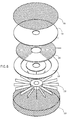
- Fig. 6 is an exploded view illustration of induction heating apparatus constructed and operative in accordance with a preferred embodiment of the present invention;
- Fig. 7A is a top view illustration, partially enlarged, of a foil assembly forming part of the embodiment of Fig. 6;
- Figs. 7B, 7C, 7D, 7E, 7F, 7G and 7H are top view illustrations of alternative embodiments of a magnetic field conductor useful in the embodiment of Fig. 6;
- Fig. 8 is a side view illustration of a stirring assembly constructed and operative in accordance with a preferred embodiment of the present invention;
- Figs. 9A and 9B are plan view and edge view illustrations of a stirring coupler constructed and operative in accordance with a preferred embodiment of the present invention;
- Figs. 10A, 10B and 10C are three illustrations of stages in the engagement of part of the stirring assembly of Fig. 8 with the coupler of Figs. 9A and 9B;
- Figs. 11A and 11B are respective side and plan view illustrations of stirring drive apparatus useful in association with the apparatus of Figs. 8 - 10C;
- Fig. 12 is a pictorial illustration of a stirrer particularly useful in the apparatus of Fig. 8;
- Figs. 13A, 13B and 13C are pictorial illustrations of three typical orientations of a utensil contacting member relative to the termination end of a stirrer, such as that of Fig. 12;
- Fig. 14 is a sectional illustration of an alternative embodiment of utensil contacting member; and
- Fig. 15 is a diagrammatic illustration of the area coverage produced by operation of the stirring apparatus of Fig. 8.
- Reference is now made to Figs. 1A and 1B which illustrate a cooking system constructed and operative in accordance with a preferred embodiment of the present invention and comprising a
cooking center 10, including aback portion 12 and abase portion 14, defining a plurality ofcooking locations 16, each arranged for operative association with acooking utensil 18. Preferably the top surface ofbase portion 14 is formed of ceramic glass. - The
back portion 12 and thebase portion 14 comprise various controls for each of thecooking locations 16, such as on-off, temperature and timing controls which may be embodied, for example, in aswitch 19 with associated indicator light, akeyboard 20 and adial 21. Astatus display 22, such as an LCD display, may also be provided. Also mounted onback portion 12 is acoupler 23 of a stirrer drive assembly, which is not seen in Figs. 1A - 1B, insofar as it is located at the interior ofback portion 12. - The
base portion 14 typically defines four cooking locations. Each cooking location is typically provided withinduction heating apparatus 25, which is not seen in Fig. 1A inasmuch as it is located withinbase 14. - In the embodiment of Figs. 1A and 1B, for the sake of illustration, all of the cooking locations are provided with induction heating apparatus, although this need not be the case.
- In Fig. 1B, which represents a section taken along the lines B - B in Fig. 1A, cooking utensils formed of high resistance electrically conductive materials, such as iron and stainless steel, and of low resistance electrically conductive materials, such as aluminum, may be employed. For the purposes of the present application, the term "high resistance" refers to materials having an electrical resistance within the general range extending from 0.05 ohm mm²/meter and higher, and preferably at least 0.1 ohm mm²/meter and including iron at 0.1 ohm mm²/meter and stainless steel, typically at 0.72 ohm mm²/meter. The term "low resistance" refers to materials having an electrical resistance within the general range below 0.05 ohm mm²/meter and preferably below 0.03 ohm mm²/meter and including aluminum at 0.0285 ohm mm²/meter and copper at 0.0175 ohm mm²/meter.
- A preferred embodiment of the
induction heating apparatus 25 is illustrated in Fig. 6 and comprises aninduction coil 26 comprising an electrical conductor which carries a current flow and is typically, but not necessarily, in the form of one or more coils, which lie in a single plane or alternatively in a plurality of generally parallel planes. Preferably associated withinduction coil 26 and lying thereover and thereunder are layers ofelectrical insulation 28, which may be continuous or alternatively apertured, the apertures being configured and arranged as illustrated in Fig. 6, in order to provide an air flow path therepast, which may be useful when a ventilator (not shown) is provided inbase portion 14. Disposed undercoil 26 is a magneticfield conductor assembly 30, various embodiments of which are illustrated in Figs. 7A - 7H. - In accordance with a preferred embodiment of the invention, shielding
apparatus 29 is disposed betweeninduction coil 26 andcooking location 16 for providing electric field shielding therebetween without appreciably reducing the magnetic flux provided to the cooking location and without being itself heated to an unacceptable degree. Preferablyapparatus 29 is operative to surround the induction heating apparatus and to provide electromagnetic shielding thereof, while permitting the substantially unimpeded passage of magnetic flux thereacross to the cooking location. - According to one embodiment of the invention, the shielding
apparatus 29 is formed of expanded stainless steel mesh. According to an alternative embodiment of the invention, theapparatus 29 is formed of a woven or non-woven fabric including conductive fibers, such as carbon or metal fibers. Alternatively non-conductive fibers which are coated with a conductive coating may be employed. - According to one preferred embodiment of the invention, suitable for heating cooking utensils having aluminum bottom surfaces, the
coil 26 has an inner diameter of 40 mm, an outer diameter of 170 mm and a thickness of 5.2 mm. In this example, the coil has 120 turns and is formed of Litz wire, which is formed of 96 individually lacquered filaments, each of 0.13 mm diameter. Preferably, during operation, a voltage of about 2000 volts AC is provided acrosscoil 26 at an operative frequency of 22 KHz, providing, together with magneticfield conductor assembly 30, an inductance of about 3400 microHenry. - As seen particularly in Fig. 7A, the magnetic
field conductor assembly 30, in accordance with a preferred embodiment of the invention, comprises an array of foils of a magnetic field conductive material, which are arranged to lie non-parallel and preferably generally perpendicularly to the plane or planes of theinduction coil 26, so as to minimize the generation of eddy currents in the foils. - Preferably the magnetic field conductors are formed of a high permeability material, such as an amorphous metal, and are typically each of thickness 0.025 mm. Some preferred materials are Ultraperm 10, Permenorm (5000 H2 and 5000Z) and Vitrovac 4040, all of which are commercially available from Vacuumschmelze of Human, West Germany.
- In the preferred embodiment, illustrated in Fig. 7A, a plurality of
separate foils 32, each separated from the adjacent foil by aninsulator 34, are arranged to define radially extendingsub-assemblies 36, which extend radially outward from the center of the assembly. The foils are typically retained in position by aninsulative retaining ring 38, which may be provided at any suitable radial distance from the center of the assembly. - According to a preferred embodiment of the invention, each of foils 32 has a ratio of width in the direction generally perpendicular to the plane of the
induction coil 26 relative to thickness in the plane of the induction coil of at least about 10 and preferably at least about 200. A preferable ratio is 600. - According to an alternative embodiment of the invention, illustrated in Fig. 7B, each adjacent two
sub-assemblies 36 are in fact defined by a single plurality of foils, which is bent adjacent the center of the assembly, as indicated atreference numeral 40. - According to a further alternative embodiment of the invention, illustrated in Fig. 7C, all of the
sub-assemblies 36 are together defined by a single plurality of foils which extends intermittently both radially and circumferentially. - According to a further alternative embodiment of the invention, illustrated in Fig. 7D, one or a plurality of foils is arranged in a continuous undulating generally
parallel array 41 having an overall generally square configuration. In Fig. 7E, an undulatingarray 43 has an overall generally circular configuration, underlyingcoil 26. - In Figs. 7F and 7G, an array of separate parallel foils or groups of foils is provided. In Fig. 7F, the overall configuration of the
array 45 is square, while in Fig. 7G, the overall configuration of thearray 47 is circular and conforms to the configuration ofcoil 26. - In accordance with a further alternative embodiment of the present invention, illustrated in Fig. 7H, the magnetic
field conductor assembly 30 may comprise aferromagnetic wire 48 wound in a generally toroidal arrangement to define a plurality ofloops 49, each of which is disposed generally in a plane generally perpendicular to the plane ofcoil 26. - It is a further particular feature of the present invention that the inductively heated cooking utensil need not necessarily have a flat bottom surface or a flat food cooking surface.
- It is a particular feature of the invention that the magnetic flux produced by
induction coil 26 in response to passage of suitable current therethrough is spatially defined by theutensil 18 and by magneticfield conductor assembly 30. The use ofthin foils 32 or loops extending generally non-parallel and preferably generally perpendicularly to the plane of theinduction coil 26 instead of a thicker body of ferromagnetic material lowers the heating of theinduction heating apparatus 25 as compared with the heating which would occur in a relatively thicker body of ferromagnetic material, such as ferrite, particularly if oriented parallel to the plane of the coil, thus increasing efficiency and inductance. - It is a particular feature of the present invention that foils 32 or
wire 48 are formed of a material, such as amorphous metal, which has a relatively high Curie temperature and high permeability, especially at the operating frequency ofinduction heating apparatus 25, typically 22 KHz. - Reference is now made to Fig. 1C, which illustrates a system which is generally similar to that of Fig. 1B, except as described hereinbelow. In the embodiment of Fig. 1C, the
cooking utensil 13 is formed of a metal and defines acurved cooking surface 15. There is also provided aheat transfer member 17, formed of a metal and having a curved top surface engaging the underside of the curved cooking surface and a generally flat bottom surface. - In accordance with a preferred embodiment of the invention, the
cooking utensil 13 is formed to have a metal surface having a high electrical resistance and theheat transfer member 17 is formed of a metal having a low electrical resistance. This structure is particularly suitable for use with induction heating apparatus, such as that illustrated atreference number 25 in Fig. 1C. Alternatively bothelements reference numeral 24. If a conventional resistance heating element is employed, the utensil may be formed of any suitable material, which need not necessarily be metal. -
Induction heating apparatus 25 is generally similar to that shown in Fig. 1B and described hereinabove. It may, however, be modified as will now be described. These modifications may also be employed where suitable in the various other embodiments of the invention described in the specification.Vibration absorbing apparatus 27 is preferably provided between theinduction heating apparatus 25 and both the top and bottom surfaces of thebase portion 14. Additionally, the top surface of thebase portion 14 above each cooking location may be vibrationally decoupled from the remainder of the top surface of the base portion. - Reference is now made to Fig. 2 which illustrates the modularity and flexibility of the cooking system of the present invention, wherein a single cooking location may alternatively accommodate a plurality of different utensils having different configurations, including, for example, both flat and curved bottom surfaces. In accordance with a preferred embodiment of the invention, utensils having bottom surfaces of either high or low electrical resistance, such as copper and aluminum, may be used with the present invention.
- The utensils usable with the present invention include both special purpose utensils including stirring apparatus as well as entirely conventional cooking utensils, such as those seen in Fig. 2.
- Control apparatus employed in the cooking center is illustrated in Fig. 3 and includes
user interface apparatus 50, typically incorporatingswitch 19,keyboard 20 and dial 21 (Fig. 1A), which provide control inputs relating to desired cooking time and desired temperature to controlcircuitry 52.Control circuitry 52 also receives a temperature input fromtemperature sensing apparatus 54 and provides a trigger output toinduction heating assembly 56, a stirring control output to a stirringassembly 58, described hereinbelow, and a display output to adisplay 60, such as display 22 (Fig. 1). A detailed schematic illustration of the control circuitry appears in Figs. 4A, 4B, 4C, 4D, 4E and 4F, it being noted that theuser interfaces 50,cooking temperature sensors 54 andinduction heating assembly 56 for only one cooking location are shown. - Preferably, the
induction heating assembly 56 includes aninduction coil 26 which is powered by switching power and control circuitry which provides a train of AC pulses having a frequency of about 22 KHz. The control circuitry, illustrated in Figs. 4A - 4F, includes apower circuit 200, typically receiving a 220Volt 50 cycle, electric mains input. Thepower circuit 200 comprises abridge rectifier 202 and a pair ofcapacitors capacitors high voltage relay 208 to one of twocapacitors induction coil 26. -
Relay 208 is operative to adapt the induction producing apparatus of the present invention for use with cooking utensils whose bottom surfaces have either high or low electrical resistance. When a cooking utensil having a bottom surface with high electrical resistance, such as stainless steel, is employed, therelay 208 connects the junction ofcapacitors induction coil 26, viacapacitor 212. When a cooking utensil having a bottom surface with a low electrical resistance, such as aluminum, is employed, therelay 208 connects the junction ofcapacitors induction coil 26 viacapacitor 210. - The interior turn of the
induction coil 26 is coupled viasampling apparatus 220 to the junction of two series connected transistor switches 214 and 216, which are operative to provide a high frequency driving voltage across theinduction coil 26 and either ofcapacitors -
First sampling apparatus 218 samples the mains current, whilesecond sampling apparatus 220 samples the peak current oftransistor switches apparatus 218 passes throughcircuitry 221 to a voltage controlledoscillator 224 which increases its output frequency as the sensed mains current increases. - The sampled information from
apparatus 220 is processed by acurrent detector 226 and is used to select the switching condition ofrelay 208. It is appreciated thatapparatus 220 is operative to determine whether a utensil being heated by the induction heating apparatus of the present invention has a bottom surface with a high or low electrical resistance. In this way, the apparatus of the present invention is able to distinguish between, for example, utensils having stainless steel and aluminum bottoms and to be operative to safely and efficiently heat both types of utensils. - According to an alternative embodiment of the present invention,
relay 208 may be eliminated and the apparatus of the present invention may be designed to operate only with utensils having either high or low electrical resistance bottom surfaces. - The sampled information from
apparatus 220 is also supplied tocircuitry 228 and is employed for protecting circuit elements. - Circuitry 230 (Figs. 4A and 4B) provides timing, induction heating control, motor control and display functions.
- It is particular feature of the present invention that the circuitry of Fig. 4C includes
temperature sensors 54 which measure temperature by sensing the current flow passing throughinduction coil 26. Variations in the current flow provide indications of variations in temperature. - Reference is now made to Fig. 5, which is a generalized flow chart illustrating the operation of the circuitry of Figs. 4A - 4F. As can be seen from the flow chart, upon turning on the system for a cooking location by operating
switch 19, following system initialization and fault checks, the system determines if a utensil located at the cooking location has a bottom surface having high or low electrical resistance and adapts the operation of the circuitry of Figs. 4A - 4F, such as by means ofrelay 208, accordingly. Alternatively, where the system is adapted for use only for utensils whose bottom surface has either a high or low electrical resistance, the system will operate only in the presence of the appropriate type of utensil. - Normally the system will periodically check to ensure that the utensil having an indicated resistance has remained at the cooking location, in order to prevent damage to the induction heating system or inefficient operation thereof.
- The system checks the desired temperature indicated by
dial 21 and compares it with the temperature indicated by the temperature sensing apparatus. The induction heating assembly is operated as appropriate. - The following subroutine may be employed at this stage:
- 1. Operate the
induction coil 26 and measure the temperature every 10 seconds until the predetermined desired temperature indicated bydial 21 is reached; - 2. When the measured temperature exceeds the predetermined temperature, such as 100 degrees Centigrade, shift to pulsed operation of the induction heating generator (such as operation for one second followed by a 10 seconds interval) until the measured temperature falls below the predetermined temperature and return to
step 1. - According to an alternative embodiment of the invention, when the measured temperature is less than the predetermined temperature, instead of
step 2, the induction heating apparatus may be operated continuously until a weighted temperature is reached, the weighted temperature being greater than the predetermined temperature, typically by a factor of about 1.2 times the difference between the measured temperature and the predetermined temperature. Once the measured temperature reaches the weighted temperature, the induction heating apparatus is operated according tostep 2. - Additionally the system operates to monitor the remaining desired cooking time and the ON status of
switch 19. It provides for operation of the stirring device throughout cooking or as desired by the user. Upon termination of the desired cooking time, the induction heating apparatus is turned off and the stirring is typically continued for a given period and then terminated. Visual and/or auditory notification of completed cooking may be provided to the user. - Reference is now made to Figs. 8 - 15 which illustrate stirring apparatus constructed and operative in accordance with a preferred embodiment of the present invention. The stirring apparatus including a stirring assembly, indicated generally by
reference numeral 60, is illustrated most clearly in Fig. 8. - Stirring
assembly 60 is arranged for removable and automatic driving engagement with stirring drive apparatus, which is illustrated in Figs. 11A and 11B, via coupling apparatus, indicated generally byreference numeral 62. The coupling apparatus includes afirst engagement portion 120, which is described in detail in Figs. 9A and 9B and which undergoes reciprocating rotation about anaxis 64 and asecond engagement portion 66 having apolygonal engagement recess 68.Second engagement portion 66 andrecess 68 are arranged symmetrically with respect toaxis 64 for rotation thereabout. - The stirring
assembly 60 comprises anaxle portion 70 including ahousing 72 and aninternal drive shaft 74.Housing 72 is formed with aperpendicularly extending arm 73, which terminates adjacent aprotrusion 75, extending perpendicularly toarm 73. -
Internal drive shaft 74 is formed at one end thereof with apolygonal engagement protrusion 76 which is configured to mate withrecess 68. At an opposite end thereof, driveshaft 74 is provided with aconical gear 78.Conical gear 78 drivingly engages a correspondingconical gear 80 which is fixedly associated with a firststirrer drive axle 82. - First
stirrer drive axle 82 is seated withinhousing 72 and is provided with apolygonal bore 84 extending therethrough for receiving theshaft 86 of astirrer 90. Firststirrer drive axle 82 is also provided with adrive gear 92, which drivingly engages a firstintermediate gear 94 on a firstintermediate axle 96. -
Intermediate gear 94 drivingly engages adriving gear 98 which is mounted on anaxle 100, which optionally can serve as a stirrer drive axle, in which case it is formed with an appropriate bore. Drivinggear 98 drivingly engages a secondintermediate gear 102 on a secondintermediate axle 104.Intermediate gear 102 drivingly engages adriving gear 106 which is mounted on a secondstirrer drive axle 108, which along withgears axles housing 72 and which is provided with apolygonal bore 109, extending therethrough, for receiving theshaft 110 of astirrer 112. - It is appreciated that when two stirrers are employed, as illustrated in Fig. 8, stirring
drive axles drive axle 100. - Reference is now made to Figs. 11A and 11B which illustrate stirring drive apparatus useful in the present invention. A
first motor 128 has itsdrive shaft 130 coupled, via agear 131, to a two stage reducingplanetary gear assembly 132, whose output drives ashaft 134 which is rotatably mounted into ahousing 136. -
Engagement portion 66 is spring mounted intoshaft 134 for driven rotation together therewith aboutaxis 64 and permitting retraction of thestem 138 ofengagement portion 66 into the interior ofshaft 134 against the urging of aspring 140. - A
second motor 142 has its drive shaft 144 coupled, via agear 145, to a three stage reducingplanetary gear assembly 146, whose output drives ashaft 148 onto which is mounted arotating drive arm 150. Rotatably mounted ontodrive arm 150 is one end of a reciprocating crank 152 whose opposite end is rotatably coupled toarm 154, which is mounted for rotation aboutaxis 64 and is coupled to asleeve 156 for drivingarm 121 in reciprocating rotational motion aboutaxis 64. - As seen in Fig. 8, fixedly mounted to hollow
shaft 164 is perpendicularly extendingdrive arm 121 onto which is fixedly mountedfirst engagement member 122. - Reference is now made to Figs. 9A and 9B which illustrate a preferred embodiment of
coupler engagement portion 120. Theengagement member 122 generally comprises a bifurcated cone whose center is slotted by aslot 124 having inclinedside walls 126. - Reference is now made to Figs. 10A, 10B and 10C which illustrate steps in the engagement of
protrusion 75 withengagement portion 120. In Fig. 10A, theprotrusion 75 is shown alongside theengagement portion 120. In Fig. 10B, theprotrusion 75 is shown at the top ofengagement member 122, adjacent slot 124 (Fig. 9A), as mountingarm 121 is bent correspondingly. Fig. 10C illustrates seating of theprotrusion 75 inslot 124, such that rotation of thehollow shaft 164 about itsrotation axis 64, produces rotation of the entire stirring assembly aboutrotation axis 64. - It is noted that engagement of
protrusion 76 inrecess 68 and rotation ofshaft 164 aboutaxis 64 produce rotation of theindividual stirrers - Reference is now made to Figs. 12 - 15 which illustrate the structure and operation of stirrers in accordance with a preferred embodiment of the present invention. Fig. 12 illustrates a
stirrer 90 having ashaft 86 formed with aretractable retaining protrusion 180 at the top thereof. Acoil spring 182 may be disposed about the bottom portion of theshaft 86 to sit on anenlarged shaft portion 184 whosetop surface 186 defines a spring seat. - Extending downward from
enlarged shaft portion 184 is a generally spiral stirringelement 190 of increasing radius. Theelement 190 is relatively thin and its overall configuration is generally conical. - Disposed at a
termination end 191 of the stirringelement 190 is autensil contacting member 192, which rides along the inner surface of a utensil during stirring. It is a particular feature of the invention that the stirrer is arranged to accommodate surfaces at varying angles and distances from the axis ofrotation 64 of the stirring assembly. - As seen in Figs. 13A, 13B and 13C, the
utensil contacting member 192 is coupled to thetermination end 191 by a connector which allows theutensil contacting member 192 to assume varying orientations relative to thetermination end 191. - Fig. 14 illustrates an alternative embodiment of
utensil contacting member 193 which defines aball socket 195. Here thetermination end 197 of the stirrer is formed with a balljoint protrusion 199 which is arranged for rotatable seating insocket 195. - As seen in Fig. 8, when considering the two different rotational orientations shown for
stirrers utensil contacting member 192 and theaxis 64 varies within given limits, theshaft 86 of the stirrer rises or lowers relative to theaxis 64 inbores springs 182, if springs are provided. It is noted that although the twostirrers - Reference is now made to Fig. 15, which illustrates the pattern of coverage of an inner surface of a
utensil 18. It is seen that the rotation of the utensil contacting members covers generally the entire surface of a major portion of the utensil, which normally is heated and thus prevents sticking and burning of food in engagement therewith during cooking. - It will be appreciated by persons skilled in the art that the present invention is not limited by what has been particularly shown and described hereinabove. It is appreciated that any combination of the features shown in the drawings also may lie within the scope of the invention. The scope of the present invention is defined only by the claims which follow:
Claims (37)
- A domestic cooking system useful for heating utensils having a bottom surface formed of a metal having low electrical resistance and comprising:
electromagnetic induction apparatus including an induction coil having more than 80 turns. - A domestic cooking system according to claim 1 and wherein said induction coil has more than 100 turns.
- A domestic cooking system useful for heating a utensil having a bottom surface formed of a metal having low electrical resistance and comprising:
electromagnetic induction apparatus including an induction coil receiving an AC electrical input at a frequency less than 50 KHz. - A domestic cooking system according to claim 3 and wherein said induction coil receives an AC electrical input at a frequency less than 30 KHz.
- A domestic cooking system useful for heating a utensil having a bottom surface formed of a metal having low electrical resistance and comprising:
electromagnetic induction apparatus including an induction coil having a voltage of less than 4000 Volts thereacross during operation. - A domestic cooking system useful for heating utensils having a bottom surface formed of a metal having low electrical resistance and comprising:
electromagnetic induction apparatus including induction producing means producing inductance of at least 1000 microHenry. - A domestic cooking system according to claim 6 and wherein said induction producing means produces inductance in excess of 2000 microHenry.
- A domestic cooking system comprising:
a base defining at least one cooking location;
electromagnetic induction apparatus for heating a food at said at least one cooking location; and
means for automatic stirring of the food at said at least one cooking location. - A domestic cooking system comprising:
electromagnetic induction apparatus for heating a food at a cooking location by providing magnetic flux to said cooking location; and
means for providing electric field shielding at least between said electromagnetic induction apparatus and said cooking location. - A domestic cooking system according to claim 9 and wherein said means for providing electric field shielding is operative to surround said electromagnetic induction apparatus and to provide electromagnetic shielding thereof, while permitting the substantially unimpeded passage of magnetic flux thereacross to said cooking location.
- A domestic cooking system useful for heating a utensil having a bottom surface formed of a metal having low electrical resistance and comprising:
electromagnetic induction apparatus for heating a food at a cooking location, said electromagnetic induction apparatus normally operating in a non-resonant mode. - A domestic cooking system according to claim 11 and wherein said electromagnetic induction apparatus comprises an induction coil and high frequency switching means and means for providing negative feedback to said high frequency switching means.
- A domestic cooking system useful for heating utensils of a first type, having a bottom surface having high electrical resistance and of a second type, having a bottom surface having low electrical resistance, said system comprising:
electromagnetic induction apparatus including an induction coil;
automatic control means for governing the operation of the electromagnetic induction apparatus and being operable in first and second modes, said first mode being suitable for heating utensils of said first type and employing a first number of turns of said induction coil and said second mode being suitable for heating utensils of said second type and employing a second number of turns of said induction coil, larger than said first number of turns,
means for supplying an AC electrical power input to the induction coil generally at the same frequency during operation in both said first and second modes. - A domestic cooking system comprising:
a base defining at least one cooking location and comprising electromagnetic induction apparatus including:
an induction coil disposed generally in at least one plane and operative to generate electromagnetic flux; and
at least one magnetic field conductor disposed in a plane extending generally non-parallel to said at least one plane so as to direct electromagnetic flux generated by the induction coil to said at least one cooking location. - Apparatus according to claim 14 wherein said at least one magnetic field conductor comprises a ferromagnetic foil which is disposed generally perpendicular to said at least one plane and includes portions which extend generally radially.
- Apparatus according to claim 14, and wherein said at least one magnetic field conductor comprises at least one ferromagnetic wire wound in a generally toroidal arrangement to define a plurality of loops, each of which is disposed in a plane generally perpendicular to said at least one plane.
- A domestic cooking system according to claim 15 and wherein said at least one ferromagnetic foil has a ratio of width in the direction generally perpendicular to the at least one plane relative to thickness of at least 100.
- A domestic cooking system according to any of the preceding claims 14 - 17 and wherein said at least one magnetic field conductor comprises amorphous metal.
- A domestic cooking system according to any of the preceding claims 14 - 18 and wherein each of said at least one magnetic field conductor has a thickness of less than 0.3 mm.
- A domestic cooking system according to any of claims 3 - 19 and wherein said electromagnetic induction apparatus includes an induction coil having more than 80 turns.
- A domestic cooking system according to any of claims 1, 2, and 5 - 20 and wherein said electromagnetic induction apparatus includes induction producing means receiving an AC electrical input at a frequency less than 50 KHz.
- A domestic cooking system according to any of claims 1 - 4 and 6 - 21 and wherein said electromagnetic induction apparatus includes induction producing means having a voltage thereacross during operation of less than 4000 Volts.
- A domestic cooking system according to any of claims 1 - 8 and 11 - 22 and also comprising means for providing electric field shielding at least between said electromagnetic induction apparatus and a cooking location.
- Apparatus according to any of the preceding claims 1 - 7 and 9 - 23 and also comprising automatically operative stirring apparatus.
- Apparatus according to any of the preceding claims and also including apparatus for obtaining temperature information relating to a utensil from variations in the current passing through said induction coil and for controlling the supply of heat to the utensil in accordance with the temperature of the utensil.
- Apparatus according to claim 25 and wherein said apparatus for obtaining and for controlling also comprises timing apparatus.
- A domestic cooking system according to any of the preceding claims and also comprising a utensil having a curved cooking surface having a generally circular cross sectional configuration and also comprising stirring apparatus including:
at least one stirrer arranged about a stirrer rotation axis and defining an attachment end and a termination end;
means for rotating said at least one stirrer about said stirrer rotation axis; and
means for reciprocatingly rotating said at least one stirrer about a reciprocal motion axis transverse to said stirrer rotation axis such that said termination end moves along said curved cooking surface. - For use with a utensil having a curved cooking surface having a generally circular cross sectional configuration, stirring apparatus comprising:
at least one stirrer arranged about a stirrer rotation axis and defining an attachment end and a termination end;
means for rotating said at least one stirrer about said stirrer rotation axis; and
means for reciprocatingly rotating said at least one stirrer about a reciprocal motion axis perpendicular to said stirrer rotation axis such that said termination end moves along said curved cooking surface. - Apparatus according to either of claims 27 or 28 and wherein said stirrer has a generally screw-type configuration.
- Apparatus according to any of claims 27 - 29 and wherein said stirring apparatus comprises stirring drive apparatus and a stirrer, said stirring drive apparatus including quick coupling apparatus for automatically coupling the stirrer drive apparatus to said stirrer.
- Apparatus according to any of claims 27 - 30 and also comprising a utensil contacting member mounted onto the termination end of said stirrer and being selectably orientable with respect thereto so as to correspond to the configuration of the utensil surface in engagement therewith.
- Stirring apparatus comprising:
a stirrer having an attachment end and a termination end;
means for mounting said stirrer at said attachment end and driving said stirrer in motion in operative association with a utensil defining a utensil surface; and
a utensil contacting member mounted onto the termination end of said stirrer and being selectably orientable with respect thereto so as to correspond to the configuration of the utensil surface in engagement therewith. - A cooking temperature sensor for use with a domestic cooking system including an induction heating means including an induction coil and means for measuring temperature by sensing variations in the current flow passing through the induction coil.
- A cooking utensil formed of a metal and defining a curved cooking surface and also comprising a heat transfer member formed of a metal, said heat transfer member defining a curved top surface engaging the underside of the curved cooking surface and a generally flat bottom surface.
- Apparatus according to claim 34 and also comprising:
means for providing heating of the flat bottom surface, thereby heating said cooking surface. - Apparatus according to any of claims 1 - 7, 11, 12, 19 - 32 and wherein said utensil is formed of a metal and defines a curved cooking surface and said apparatus also comprises a heat transfer member, said heat transfer member defining a curved top surface engaging the underside of the curved cooking surface and a generally flat bottom surface.
- Apparatus according to either of claims 34 and 36 and wherein said cooking utensil is formed of a metal having a high electrical resistance and said heat transfer member is formed of a metal having a low electrical resistance.
Applications Claiming Priority (4)
| Application Number | Priority Date | Filing Date | Title |
|---|---|---|---|
| IL94178 | 1990-04-24 | ||
| IL94178A IL94178A0 (en) | 1990-04-24 | 1990-04-24 | Cooking device |
| IL95793 | 1990-09-25 | ||
| IL95793A IL95793A (en) | 1990-09-25 | 1990-09-25 | Cooking device |
Publications (3)
| Publication Number | Publication Date |
|---|---|
| EP0453634A2 true EP0453634A2 (en) | 1991-10-30 |
| EP0453634A3 EP0453634A3 (en) | 1993-03-03 |
| EP0453634B1 EP0453634B1 (en) | 1996-01-31 |
Family
ID=26322078
Family Applications (1)
| Application Number | Title | Priority Date | Filing Date |
|---|---|---|---|
| EP90121864A Expired - Lifetime EP0453634B1 (en) | 1990-04-24 | 1990-11-15 | Cooking device |
Country Status (10)
| Country | Link |
|---|---|
| US (2) | US5412171A (en) |
| EP (1) | EP0453634B1 (en) |
| JP (1) | JPH046791A (en) |
| AT (1) | ATE133829T1 (en) |
| AU (1) | AU636412B2 (en) |
| CA (1) | CA2030608A1 (en) |
| DE (1) | DE69025174T2 (en) |
| ES (1) | ES2081899T3 (en) |
| IE (1) | IE903986A1 (en) |
| NZ (1) | NZ236153A (en) |
Cited By (11)
| Publication number | Priority date | Publication date | Assignee | Title |
|---|---|---|---|---|
| ES2073999A2 (en) * | 1993-06-01 | 1995-08-16 | Fagor S Coop Ltda | Power control system in an induction hob. |
| US5574104A (en) * | 1990-01-05 | 1996-11-12 | The B. F. Goodrich Company | Chain extended low molecular weight polyoxiranes and electrostatic dissipating blend compositions based thereon |
| EP0761296A1 (en) * | 1995-08-24 | 1997-03-12 | Vakumix Rühr- und Homogenisiertechnik Aktiengesellschaft | Scraping device |
| WO2010054295A3 (en) * | 2008-11-07 | 2010-08-19 | Lance Johnson | Anti-oxidation food preparation device |
| CN102100484A (en) * | 2011-03-04 | 2011-06-22 | 曾令斌 | Electromagnetic oven heated kettle capable of automatically stopping heating |
| EP2893854A1 (en) * | 2014-01-10 | 2015-07-15 | Electrolux Appliances Aktiebolag | Induction cooker |
| EP3544374A1 (en) * | 2018-03-23 | 2019-09-25 | Whirlpool Corporation | Induction cooktop with improved magnetic flux concentrating foil |
| WO2020182262A1 (en) | 2019-03-12 | 2020-09-17 | Norqi Aps | An induction heated kettle |
| US11388785B2 (en) | 2018-03-23 | 2022-07-12 | Whirlpool Corporation | Connection interface for induction coil array |
| US11405989B2 (en) | 2018-03-23 | 2022-08-02 | Whirlpool Corporation | Temperature sensor compression features for induction cooktop assembly |
| EP4075922A1 (en) * | 2021-04-16 | 2022-10-19 | Vestel Elektronik Sanayi ve Ticaret A.S. | Cooking vessel, cooking system, and method |
Families Citing this family (40)
| Publication number | Priority date | Publication date | Assignee | Title |
|---|---|---|---|---|
| US7133726B1 (en) * | 1997-03-28 | 2006-11-07 | Applera Corporation | Thermal cycler for PCR |
| US5881632A (en) * | 1997-09-02 | 1999-03-16 | Fadoul; Fadoul George | Automatic cooking apparatus |
| US5901637A (en) * | 1998-04-06 | 1999-05-11 | Appliance Development Corporation | Combined baking oven and automatic bread baking apparatus |
| DE29815934U1 (en) * | 1998-09-04 | 1998-12-10 | Quality & Strength Inc | Kitchen utensil for fruits and vegetables |
| AU2003242176A1 (en) * | 2002-05-31 | 2003-12-19 | Xiaoyong Liu | Automatic food cooking apparatus |
| DE10231122A1 (en) * | 2002-07-05 | 2004-01-22 | E.G.O. Elektro-Gerätebau GmbH | Method of measuring the temperature of a metal cooking vessel |
| US6953919B2 (en) | 2003-01-30 | 2005-10-11 | Thermal Solutions, Inc. | RFID-controlled smart range and method of cooking and heating |
| ATE428334T1 (en) * | 2003-10-17 | 2009-05-15 | Xiaoyong Liu | INTELLIGENT COOKING PROCESS |
| US7270536B2 (en) * | 2004-05-13 | 2007-09-18 | Husky Injection Molding Systems Ltd. | Screw tip and molding system apparatus |
| US20060044935A1 (en) * | 2004-08-25 | 2006-03-02 | Benelli Brandon P | Method and system for producing a temperature profile in a food preparation container |
| US20060146645A1 (en) * | 2005-01-06 | 2006-07-06 | Rosener William J | MagnaStir |
| US20080282904A1 (en) * | 2005-01-12 | 2008-11-20 | Xiaoyong Liu | Automatic or Semi-Automatic Turning Method and Device |
| US7446288B2 (en) * | 2005-05-06 | 2008-11-04 | Applied Biosystems Inc. | Device including inductively heatable fluid retainment region, and method |
| FR2895638B1 (en) * | 2005-12-27 | 2008-04-18 | Brandt Ind Sas | INDUCING DEVICE WITH MULTIPLE INDIVIDUAL WINDINGS FOR INDUCTION COOKING FIREPLACE |
| US20070170177A1 (en) * | 2006-01-20 | 2007-07-26 | Avendano Jose G | Power management apparatus, system and method for vending machine |
| US20070170174A1 (en) * | 2006-01-20 | 2007-07-26 | Segiet William W | Food inductive heating device and method |
| US20090084777A1 (en) * | 2006-10-02 | 2009-04-02 | Oh Doo Yong | Cooking device having an induction heating element |
| US20080239867A1 (en) * | 2007-03-28 | 2008-10-02 | Gilbert Donna J | Adjustable stir |
| WO2009057185A1 (en) * | 2007-10-29 | 2009-05-07 | Shimadzu Corporation | Cvd device |
| US8813635B2 (en) * | 2008-01-17 | 2014-08-26 | Marinela Luminita Dragan | Steam-heat-only, food-preparation bowl structure and related methodology |
| EP2349549B1 (en) * | 2008-09-16 | 2012-07-18 | Ibis Biosciences, Inc. | Mixing cartridges, mixing stations, and related kits, and system |
| JP5164824B2 (en) * | 2008-12-19 | 2013-03-21 | 三菱電機株式会社 | Cooker |
| CN201365481Y (en) * | 2009-02-13 | 2009-12-23 | 东莞市前锋电子有限公司 | Electromagnetic type barbecue oven |
| US8226290B1 (en) * | 2009-10-22 | 2012-07-24 | Tolufashe Eunice K | Combined cooking and mashing device |
| TWI418255B (en) * | 2009-11-09 | 2013-12-01 | Delta Electronics Inc | Smart heating apparatus and temperature measuring apparatus |
| GB2502583B (en) * | 2012-05-31 | 2017-09-06 | Stratec Biomedical Ag | A device for incubating a sample |
| US10105665B2 (en) * | 2012-06-22 | 2018-10-23 | Mark E. Goodson | Beverage mixing system and method |
| US9610553B2 (en) * | 2012-06-22 | 2017-04-04 | Mark E. Goodson | Beverage mixing system and method |
| US10926233B2 (en) | 2012-06-22 | 2021-02-23 | Mark E. Goodson | Beverage mixing system and method |
| US20160037956A1 (en) | 2013-02-14 | 2016-02-11 | Jeff Wu | Circulator cooker |
| US20150082996A1 (en) | 2013-09-20 | 2015-03-26 | Jeff Wu | Submersable circulator cooker |
| US20150334785A1 (en) * | 2014-05-15 | 2015-11-19 | Cooktek Induction Systems, Llc | Menu-based cooking appliance |
| JP6463508B2 (en) | 2015-01-16 | 2019-02-06 | ココテッラ カンパニーCocoTerra Company | Chocolate processing system and method |
| US20170202059A1 (en) * | 2016-01-12 | 2017-07-13 | Electrolux Home Products, Inc. | Induction stirring apparatus for induction cooktops |
| CN109073230B (en) * | 2016-04-06 | 2019-12-06 | 三菱电机株式会社 | Heating cooking system, induction heating cooker, and cooking device |
| WO2017193531A1 (en) * | 2016-05-13 | 2017-11-16 | 佛山市顺德区美的电热电器制造有限公司 | Cooking utensil |
| US11026535B2 (en) | 2016-11-30 | 2021-06-08 | Illinois Tool Works Inc. | Oven with machine learning based algorithm selection strategy |
| US11665790B2 (en) * | 2016-12-22 | 2023-05-30 | Whirlpool Corporation | Induction burner element having a plurality of single piece frames |
| US11470853B2 (en) | 2019-03-15 | 2022-10-18 | CocoTerra Company | Interface and application for designing a chocolate-making experience |
| US11375843B2 (en) | 2019-04-12 | 2022-07-05 | Anova Applied Electronics, Inc. | Sous vide cooker |
Citations (6)
| Publication number | Priority date | Publication date | Assignee | Title |
|---|---|---|---|---|
| US3761668A (en) * | 1972-03-01 | 1973-09-25 | Gen Electric | Small electrical apparatus powered by induction cooking appliances |
| US4467162A (en) * | 1980-06-13 | 1984-08-21 | Riccar Co., Ltd. | Exciting arrangement for induction heating process |
| US4749836A (en) * | 1985-11-27 | 1988-06-07 | Kabushiki Kaisha Toshiba | Electromagnetic induction cooking apparatus capable of providing a substantially constant input power |
| GB2199454A (en) * | 1986-11-29 | 1988-07-06 | Toshiba Kk | Induction heated cooking apparatus |
| EP0277075A2 (en) * | 1987-01-13 | 1988-08-03 | Cableco | Induction heating for an electric cooling plate |
| FR2630630A1 (en) * | 1988-04-29 | 1989-11-03 | Yahav Shimon | HOUSEHOLD APPLIANCE FOR COOKING FOOD |
Family Cites Families (58)
| Publication number | Priority date | Publication date | Assignee | Title |
|---|---|---|---|---|
| US774350A (en) * | 1904-03-02 | 1904-11-08 | Lizzie Pettis Castle | Fruit-colander. |
| US1491991A (en) * | 1923-07-18 | 1924-04-29 | Karlac Company | Beverage mixer and heater |
| US1790115A (en) * | 1924-07-25 | 1931-01-27 | Sprague Sells Corp | Apparatus for treating food products |
| US1642531A (en) * | 1925-06-08 | 1927-09-13 | Therides V Barnard | Popping kettle |
| US1674692A (en) * | 1926-11-30 | 1928-06-26 | Ti Co Mfg Co | Portable electric roaster |
| US1786877A (en) * | 1928-02-20 | 1930-12-30 | Nat Sales And Mfg Company | Corn popper |
| US1901314A (en) * | 1930-07-03 | 1933-03-14 | Michael W Mcardle | Griddle |
| US2039277A (en) * | 1935-02-25 | 1936-05-05 | Baehr Henry | Dough machine attachment |
| US2345063A (en) * | 1939-11-13 | 1944-03-28 | Nauta Johannes Ewardus | Mixing apparatus, especially adapted for mixing pulverized materials |
| US3109633A (en) * | 1959-06-02 | 1963-11-05 | Nautamix N V | Mixing apparatus |
| US3307009A (en) * | 1962-11-30 | 1967-02-28 | Charles F Schroeder | Electromagnetic heating unit |
| US3407872A (en) * | 1967-03-30 | 1968-10-29 | Internat Agri Systems Inc | Heat exchange tank |
| NL6919610A (en) * | 1969-12-30 | 1971-07-02 | ||
| US3635147A (en) * | 1970-07-23 | 1972-01-18 | Wallace G T Lee | Combination cooking-stirring vessel |
| US3742679A (en) * | 1970-11-23 | 1973-07-03 | C Jordan | Stretchable pet suit with boots |
| US3814888A (en) * | 1971-11-19 | 1974-06-04 | Gen Electric | Solid state induction cooking appliance |
| US3770928A (en) * | 1971-12-27 | 1973-11-06 | Gen Electric | Reliable solid state induction cooking appliance with control logic |
| US3742179A (en) * | 1971-12-29 | 1973-06-26 | Gen Electric | Induction cooking appliance including wireless transmission of temperature data |
| US3786222A (en) * | 1972-04-19 | 1974-01-15 | Gen Electric | Metallic foil induction cooking |
| BE794985A (en) * | 1972-04-27 | 1973-05-29 | Petzholdt Maschf J S | VERTICAL MIXER |
| US3781505A (en) * | 1972-06-28 | 1973-12-25 | Gen Electric | Constant duty cycle control of induction cooking inverter |
| US4029926A (en) * | 1974-10-29 | 1977-06-14 | Roper Corporation | Work coil for use in an induction cooking appliance |
| US3979572A (en) * | 1974-10-29 | 1976-09-07 | Mitsubishi Denki Kabushiki Kaisha | Induction heating apparatus |
| US4092509A (en) * | 1975-05-12 | 1978-05-30 | Mitchell Mclaren P | Induction heating appliance circuit that produces relatively high frequency signals directly from a relatively low frequency AC power input |
| US4023780A (en) * | 1975-09-03 | 1977-05-17 | Egid Eugene I | Method of mixing and apparatus therefor |
| US4115677A (en) * | 1975-10-02 | 1978-09-19 | Tokyo Shibaura Electric Co., Ltd. | Induction heating apparatus |
| US4038518A (en) * | 1976-05-24 | 1977-07-26 | Morton Richard F | Dining table combined with food warming apparatus |
| US4073225A (en) * | 1976-12-17 | 1978-02-14 | N.P.I. Corporation | Rocking meatball cooker |
| JPS5435278A (en) * | 1977-08-19 | 1979-03-15 | Shigeo Takeuchi | Bread making method and apparatus |
| US4280038A (en) * | 1978-10-24 | 1981-07-21 | Ajax Magnethermic Corporation | Method and apparatus for inducting heating and melting furnaces to obtain constant power |
| JPS55144796U (en) * | 1979-04-04 | 1980-10-17 | ||
| US4492652A (en) * | 1979-12-17 | 1985-01-08 | At&T Laboratories | Reactions of aromatic compounds having two or more fused rings |
| US4426564A (en) * | 1979-12-26 | 1984-01-17 | General Electric Company | Parallel resonant induction cooking surface unit |
| DE3020167A1 (en) * | 1980-05-28 | 1981-12-03 | Dierks & Söhne, 4500 Osnabrück | Kneading and / or mixing machine |
| JPS5952028B2 (en) * | 1981-05-19 | 1984-12-17 | 新日本製鐵株式会社 | Impeder for manufacturing ERW pipes |
| US4511781A (en) * | 1981-02-23 | 1985-04-16 | Rangaire Corporation | Induction cook-top system and control |
| US4348571A (en) * | 1981-03-18 | 1982-09-07 | General Electric Company | Flux shaping arrangement for induction surface unit |
| US4417506A (en) * | 1981-09-23 | 1983-11-29 | Housewares Research Associates | Home cooking appliance |
| US4453067A (en) * | 1982-01-11 | 1984-06-05 | Whirlpool Corporation | Induction heating coil |
| AU543894B2 (en) * | 1982-09-13 | 1985-05-09 | Tokyo Shibaura Denki Kabushiki Kaisha | Electromagnetic induction heating apparatus |
| US4503502A (en) * | 1983-06-03 | 1985-03-05 | Chapin Roger A | Method and apparatus for automated chinese stir-fry cooking |
| US4617441A (en) * | 1983-07-08 | 1986-10-14 | Sanyo Electric Co., Ltd. | Temperature controlled induction heating and cooking apparatus |
| US4629843A (en) * | 1984-04-11 | 1986-12-16 | Tdk Corporation | Induction cooking apparatus having a ferrite coil support |
| JPS635196Y2 (en) * | 1984-11-27 | 1988-02-12 | ||
| US4885447A (en) * | 1985-01-23 | 1989-12-05 | Balay, S.A. | System for the induction heating of the electric plates of a cooker |
| FR2576203B1 (en) * | 1985-01-24 | 1987-06-26 | Moulinex Sa | HOUSEHOLD APPLIANCE FOR CULINARY PREPARATIONS SUCH AS SAUCES OR PASTRY LINKS |
| US4649810A (en) * | 1985-08-22 | 1987-03-17 | Wong Don M | Automatic cooking apparatus |
| US4733607A (en) * | 1985-10-07 | 1988-03-29 | Star Leonard J | Food processing machine |
| US4692610A (en) * | 1986-01-30 | 1987-09-08 | Grumman Aerospace Corporation | Fiber optic aircraft load relief control system |
| US4817510A (en) * | 1986-04-09 | 1989-04-04 | The Meyer Company | Cooking apparatus for fluid container |
| GB8625306D0 (en) * | 1986-10-22 | 1986-11-26 | Greene F A | Food processor |
| FR2608348B1 (en) * | 1986-12-10 | 1993-11-12 | Electricite De France | ELECTRICAL INDUCTION COOKING APPARATUS WITH REDUCED HARMONIC EMISSION |
| GB2203605B (en) * | 1987-04-07 | 1991-01-09 | Toshiba Kk | Electromagnetic induction heating apparatus capable of preventing undesirable states of cooking utensils or vessels |
| FR2614766B1 (en) * | 1987-05-05 | 1990-02-09 | Grandi Rene | DEVICE FOR COOKING AND COOLING FOODS ALLOWING THEIR TRANSFER BY TILTING AND ROTATING THE TANKS |
| DE3723485A1 (en) * | 1987-07-16 | 1989-01-26 | Thomson Brandt Gmbh | Inductive cooking point |
| US4820054A (en) * | 1987-12-31 | 1989-04-11 | Wong Don M | Stirring mechanism |
| US4763567A (en) * | 1988-01-11 | 1988-08-16 | Northland Aluminum Products, Inc. | Stovetop corn popper |
| IL90382A (en) * | 1989-05-23 | 1992-08-18 | Yahav Shimon | Cooking system |
-
1990
- 1990-11-05 IE IE398690A patent/IE903986A1/en unknown
- 1990-11-14 AU AU66613/90A patent/AU636412B2/en not_active Ceased
- 1990-11-15 EP EP90121864A patent/EP0453634B1/en not_active Expired - Lifetime
- 1990-11-15 DE DE69025174T patent/DE69025174T2/en not_active Expired - Fee Related
- 1990-11-15 ES ES90121864T patent/ES2081899T3/en not_active Expired - Lifetime
- 1990-11-15 AT AT90121864T patent/ATE133829T1/en not_active IP Right Cessation
- 1990-11-15 US US07/614,308 patent/US5412171A/en not_active Expired - Fee Related
- 1990-11-20 NZ NZ236153A patent/NZ236153A/en unknown
- 1990-11-22 CA CA002030608A patent/CA2030608A1/en not_active Abandoned
- 1990-11-22 JP JP2320582A patent/JPH046791A/en active Pending
-
1994
- 1994-06-20 US US08/229,812 patent/US5525781A/en not_active Expired - Fee Related
Patent Citations (6)
| Publication number | Priority date | Publication date | Assignee | Title |
|---|---|---|---|---|
| US3761668A (en) * | 1972-03-01 | 1973-09-25 | Gen Electric | Small electrical apparatus powered by induction cooking appliances |
| US4467162A (en) * | 1980-06-13 | 1984-08-21 | Riccar Co., Ltd. | Exciting arrangement for induction heating process |
| US4749836A (en) * | 1985-11-27 | 1988-06-07 | Kabushiki Kaisha Toshiba | Electromagnetic induction cooking apparatus capable of providing a substantially constant input power |
| GB2199454A (en) * | 1986-11-29 | 1988-07-06 | Toshiba Kk | Induction heated cooking apparatus |
| EP0277075A2 (en) * | 1987-01-13 | 1988-08-03 | Cableco | Induction heating for an electric cooling plate |
| FR2630630A1 (en) * | 1988-04-29 | 1989-11-03 | Yahav Shimon | HOUSEHOLD APPLIANCE FOR COOKING FOOD |
Cited By (19)
| Publication number | Priority date | Publication date | Assignee | Title |
|---|---|---|---|---|
| US5574104A (en) * | 1990-01-05 | 1996-11-12 | The B. F. Goodrich Company | Chain extended low molecular weight polyoxiranes and electrostatic dissipating blend compositions based thereon |
| ES2073999A2 (en) * | 1993-06-01 | 1995-08-16 | Fagor S Coop Ltda | Power control system in an induction hob. |
| EP0761296A1 (en) * | 1995-08-24 | 1997-03-12 | Vakumix Rühr- und Homogenisiertechnik Aktiengesellschaft | Scraping device |
| US9247841B2 (en) | 2008-11-07 | 2016-02-02 | Lance P. Johnson | Anti-oxidation food preparation device |
| WO2010054295A3 (en) * | 2008-11-07 | 2010-08-19 | Lance Johnson | Anti-oxidation food preparation device |
| CN102100484A (en) * | 2011-03-04 | 2011-06-22 | 曾令斌 | Electromagnetic oven heated kettle capable of automatically stopping heating |
| CN102100484B (en) * | 2011-03-04 | 2012-07-25 | 曾令斌 | Electromagnetic oven heated kettle capable of automatically stopping heating |
| EP2893854A1 (en) * | 2014-01-10 | 2015-07-15 | Electrolux Appliances Aktiebolag | Induction cooker |
| WO2015104144A1 (en) * | 2014-01-10 | 2015-07-16 | Electrolux Appliances Aktiebolag | Induction cooker |
| US20160286610A1 (en) * | 2014-01-10 | 2016-09-29 | Electrolux Appliances Aktiebolag | Induction cooker |
| AU2014376994B2 (en) * | 2014-01-10 | 2019-01-17 | Electrolux Appliances Aktiebolag | Induction cooker |
| CN110300471A (en) * | 2018-03-23 | 2019-10-01 | 惠而浦有限公司 | Induction cook utensil |
| EP3544374A1 (en) * | 2018-03-23 | 2019-09-25 | Whirlpool Corporation | Induction cooktop with improved magnetic flux concentrating foil |
| US11310874B2 (en) | 2018-03-23 | 2022-04-19 | Whirlpool Corporation | Induction cooktop with improved magnetic flux concentrating foil |
| US11388785B2 (en) | 2018-03-23 | 2022-07-12 | Whirlpool Corporation | Connection interface for induction coil array |
| US11405989B2 (en) | 2018-03-23 | 2022-08-02 | Whirlpool Corporation | Temperature sensor compression features for induction cooktop assembly |
| WO2020182262A1 (en) | 2019-03-12 | 2020-09-17 | Norqi Aps | An induction heated kettle |
| EP4075922A1 (en) * | 2021-04-16 | 2022-10-19 | Vestel Elektronik Sanayi ve Ticaret A.S. | Cooking vessel, cooking system, and method |
| WO2022218556A1 (en) * | 2021-04-16 | 2022-10-20 | Vestel Elektronik Sanayi Ve Ticaret A.S. | Cooking vessel, cooking system, and method |
Also Published As
| Publication number | Publication date |
|---|---|
| CA2030608A1 (en) | 1991-10-25 |
| JPH046791A (en) | 1992-01-10 |
| IE903986A1 (en) | 1991-11-06 |
| US5525781A (en) | 1996-06-11 |
| AU636412B2 (en) | 1993-04-29 |
| EP0453634A3 (en) | 1993-03-03 |
| ES2081899T3 (en) | 1996-03-16 |
| DE69025174T2 (en) | 1996-10-02 |
| ATE133829T1 (en) | 1996-02-15 |
| US5412171A (en) | 1995-05-02 |
| DE69025174D1 (en) | 1996-03-14 |
| EP0453634B1 (en) | 1996-01-31 |
| AU6661390A (en) | 1991-11-07 |
| NZ236153A (en) | 1993-11-25 |
Similar Documents
| Publication | Publication Date | Title |
|---|---|---|
| US5412171A (en) | Cooking device having stirrer movable about two mutually perpendicular axes | |
| US5070222A (en) | Heating system employing an induction producing element and a high permeability foil | |
| EP2112861B1 (en) | System and method for food preparation | |
| US10368680B2 (en) | Cookware and geometrically patterned magnetic stirrer assembly | |
| WO2010054295A2 (en) | Anti-oxidation food preparation device | |
| CN101484053B (en) | Culinary article allowing its temperature to be detected by a hob | |
| JPWO2017064804A1 (en) | Induction heating cooking apparatus, composite cooking apparatus, and induction heating cooking system including these | |
| JPH1145777A (en) | Electromagnetic heating cooker | |
| CN209574338U (en) | Continuous spiral pan | |
| CN115735412A (en) | Food preparation equipment | |
| CN115734728A (en) | Food container | |
| CN115734729A (en) | Food container | |
| CN115916014A (en) | Food container | |
| CN115734726A (en) | Food container | |
| CN115735413A (en) | Food preparation equipment | |
| JPH04181683A (en) | Electromagnetic induction heating device | |
| JPH04289686A (en) | Heating cooker | |
| JPH03194882A (en) | Electromagnetic induction cooker |
Legal Events
| Date | Code | Title | Description |
|---|---|---|---|
| PUAI | Public reference made under article 153(3) epc to a published international application that has entered the european phase |
Free format text: ORIGINAL CODE: 0009012 |
|
| AK | Designated contracting states |
Kind code of ref document: A2 Designated state(s): AT BE CH DE DK ES FR GB GR IT LI LU NL SE |
|
| PUAL | Search report despatched |
Free format text: ORIGINAL CODE: 0009013 |
|
| AK | Designated contracting states |
Kind code of ref document: A3 Designated state(s): AT BE CH DE DK ES FR GB GR IT LI LU NL SE |
|
| 17P | Request for examination filed |
Effective date: 19930730 |
|
| 17Q | First examination report despatched |
Effective date: 19940214 |
|
| GRAA | (expected) grant |
Free format text: ORIGINAL CODE: 0009210 |
|
| STAA | Information on the status of an ep patent application or granted ep patent |
Free format text: STATUS: THE PATENT HAS BEEN GRANTED |
|
| AK | Designated contracting states |
Kind code of ref document: B1 Designated state(s): AT BE CH DE DK ES FR GB GR IT LI LU NL SE |
|
| PG25 | Lapsed in a contracting state [announced via postgrant information from national office to epo] |
Ref country code: NL Free format text: LAPSE BECAUSE OF FAILURE TO SUBMIT A TRANSLATION OF THE DESCRIPTION OR TO PAY THE FEE WITHIN THE PRESCRIBED TIME-LIMIT Effective date: 19960131 Ref country code: LI Effective date: 19960131 Ref country code: GR Free format text: LAPSE BECAUSE OF FAILURE TO SUBMIT A TRANSLATION OF THE DESCRIPTION OR TO PAY THE FEE WITHIN THE PRESCRIBED TIME-LIMIT Effective date: 19960131 Ref country code: DK Effective date: 19960131 Ref country code: CH Effective date: 19960131 Ref country code: BE Effective date: 19960131 Ref country code: AT Effective date: 19960131 |
|
| REF | Corresponds to: |
Ref document number: 133829 Country of ref document: AT Date of ref document: 19960215 Kind code of ref document: T |
|
| ET | Fr: translation filed | ||
| REF | Corresponds to: |
Ref document number: 69025174 Country of ref document: DE Date of ref document: 19960314 |
|
| REG | Reference to a national code |
Ref country code: ES Ref legal event code: FG2A Ref document number: 2081899 Country of ref document: ES Kind code of ref document: T3 |
|
| ITF | It: translation for a ep patent filed |
Owner name: MODIANO & ASSOCIATI S.R.L. |
|
| PG25 | Lapsed in a contracting state [announced via postgrant information from national office to epo] |
Ref country code: SE Effective date: 19960430 |
|
| NLV1 | Nl: lapsed or annulled due to failure to fulfill the requirements of art. 29p and 29m of the patents act | ||
| REG | Reference to a national code |
Ref country code: CH Ref legal event code: PL |
|
| PG25 | Lapsed in a contracting state [announced via postgrant information from national office to epo] |
Ref country code: LU Free format text: LAPSE BECAUSE OF NON-PAYMENT OF DUE FEES Effective date: 19961130 |
|
| PLBE | No opposition filed within time limit |
Free format text: ORIGINAL CODE: 0009261 |
|
| 26N | No opposition filed | ||
| REG | Reference to a national code |
Ref country code: FR Ref legal event code: ST |
|
| REG | Reference to a national code |
Ref country code: FR Ref legal event code: RN |
|
| REG | Reference to a national code |
Ref country code: FR Ref legal event code: FC |
|
| REG | Reference to a national code |
Ref country code: GB Ref legal event code: IF02 |
|
| PGFP | Annual fee paid to national office [announced via postgrant information from national office to epo] |
Ref country code: GB Payment date: 20030402 Year of fee payment: 13 |
|
| PGFP | Annual fee paid to national office [announced via postgrant information from national office to epo] |
Ref country code: FR Payment date: 20030408 Year of fee payment: 13 |
|
| PGFP | Annual fee paid to national office [announced via postgrant information from national office to epo] |
Ref country code: DE Payment date: 20030409 Year of fee payment: 13 |
|
| PGFP | Annual fee paid to national office [announced via postgrant information from national office to epo] |
Ref country code: ES Payment date: 20030429 Year of fee payment: 13 |
|
| PG25 | Lapsed in a contracting state [announced via postgrant information from national office to epo] |
Ref country code: GB Free format text: LAPSE BECAUSE OF NON-PAYMENT OF DUE FEES Effective date: 20031115 |
|
| PG25 | Lapsed in a contracting state [announced via postgrant information from national office to epo] |
Ref country code: ES Free format text: LAPSE BECAUSE OF NON-PAYMENT OF DUE FEES Effective date: 20031117 |
|
| PG25 | Lapsed in a contracting state [announced via postgrant information from national office to epo] |
Ref country code: DE Free format text: LAPSE BECAUSE OF NON-PAYMENT OF DUE FEES Effective date: 20040602 |
|
| GBPC | Gb: european patent ceased through non-payment of renewal fee |
Effective date: 20031115 |
|
| PG25 | Lapsed in a contracting state [announced via postgrant information from national office to epo] |
Ref country code: FR Free format text: LAPSE BECAUSE OF NON-PAYMENT OF DUE FEES Effective date: 20040730 |
|
| REG | Reference to a national code |
Ref country code: FR Ref legal event code: ST |
|
| REG | Reference to a national code |
Ref country code: FR Ref legal event code: RN |
|
| REG | Reference to a national code |
Ref country code: ES Ref legal event code: FD2A Effective date: 20031117 |
|
| REG | Reference to a national code |
Ref country code: FR Ref legal event code: FC |
|
| PG25 | Lapsed in a contracting state [announced via postgrant information from national office to epo] |
Ref country code: IT Free format text: LAPSE BECAUSE OF NON-PAYMENT OF DUE FEES;WARNING: LAPSES OF ITALIAN PATENTS WITH EFFECTIVE DATE BEFORE 2007 MAY HAVE OCCURRED AT ANY TIME BEFORE 2007. THE CORRECT EFFECTIVE DATE MAY BE DIFFERENT FROM THE ONE RECORDED. Effective date: 20051115 |