EP4049852B1 - Security element, data carrier and manufacturing method - Google Patents
Security element, data carrier and manufacturing method Download PDFInfo
- Publication number
- EP4049852B1 EP4049852B1 EP22020067.9A EP22020067A EP4049852B1 EP 4049852 B1 EP4049852 B1 EP 4049852B1 EP 22020067 A EP22020067 A EP 22020067A EP 4049852 B1 EP4049852 B1 EP 4049852B1
- Authority
- EP
- European Patent Office
- Prior art keywords
- color
- security element
- visible
- luminescent
- microstructure
- Prior art date
- Legal status (The legal status is an assumption and is not a legal conclusion. Google has not performed a legal analysis and makes no representation as to the accuracy of the status listed.)
- Active
Links
- 238000004519 manufacturing process Methods 0.000 title claims description 5
- 238000007639 printing Methods 0.000 claims description 69
- 239000003086 colorant Substances 0.000 claims description 68
- 238000004020 luminiscence type Methods 0.000 claims description 56
- 239000000976 ink Substances 0.000 claims description 53
- 239000000126 substance Substances 0.000 claims description 50
- 230000005284 excitation Effects 0.000 claims description 20
- 238000000034 method Methods 0.000 claims description 7
- 238000012546 transfer Methods 0.000 claims description 6
- 238000007641 inkjet printing Methods 0.000 claims description 2
- 238000007648 laser printing Methods 0.000 claims description 2
- 238000007645 offset printing Methods 0.000 claims description 2
- 238000002211 ultraviolet spectrum Methods 0.000 claims description 2
- 239000011888 foil Substances 0.000 claims 1
- 239000000758 substrate Substances 0.000 description 24
- 238000013461 design Methods 0.000 description 23
- 239000010408 film Substances 0.000 description 8
- 238000012986 modification Methods 0.000 description 8
- 230000004048 modification Effects 0.000 description 8
- 230000000694 effects Effects 0.000 description 6
- 239000011521 glass Substances 0.000 description 6
- 239000000654 additive Substances 0.000 description 4
- 230000000996 additive effect Effects 0.000 description 4
- 238000011161 development Methods 0.000 description 4
- 230000018109 developmental process Effects 0.000 description 4
- 238000000926 separation method Methods 0.000 description 4
- 230000003595 spectral effect Effects 0.000 description 4
- 230000008901 benefit Effects 0.000 description 3
- 239000000049 pigment Substances 0.000 description 3
- 230000008569 process Effects 0.000 description 3
- 230000005855 radiation Effects 0.000 description 3
- 230000000007 visual effect Effects 0.000 description 3
- 238000010521 absorption reaction Methods 0.000 description 2
- 239000002131 composite material Substances 0.000 description 2
- 239000012634 fragment Substances 0.000 description 2
- 238000007644 letterpress printing Methods 0.000 description 2
- 239000000203 mixture Substances 0.000 description 2
- 239000006096 absorbing agent Substances 0.000 description 1
- 238000013459 approach Methods 0.000 description 1
- 238000013475 authorization Methods 0.000 description 1
- 230000000903 blocking effect Effects 0.000 description 1
- 239000000969 carrier Substances 0.000 description 1
- 230000008859 change Effects 0.000 description 1
- 239000013039 cover film Substances 0.000 description 1
- 230000001419 dependent effect Effects 0.000 description 1
- 238000000295 emission spectrum Methods 0.000 description 1
- 238000005516 engineering process Methods 0.000 description 1
- 238000000695 excitation spectrum Methods 0.000 description 1
- 238000001914 filtration Methods 0.000 description 1
- 238000007646 gravure printing Methods 0.000 description 1
- 230000036541 health Effects 0.000 description 1
- 238000005286 illumination Methods 0.000 description 1
- 230000003993 interaction Effects 0.000 description 1
- 230000000873 masking effect Effects 0.000 description 1
- 238000004806 packaging method and process Methods 0.000 description 1
- 229920000642 polymer Polymers 0.000 description 1
- 230000002265 prevention Effects 0.000 description 1
Images


Classifications
-
- B—PERFORMING OPERATIONS; TRANSPORTING
- B42—BOOKBINDING; ALBUMS; FILES; SPECIAL PRINTED MATTER
- B42D—BOOKS; BOOK COVERS; LOOSE LEAVES; PRINTED MATTER CHARACTERISED BY IDENTIFICATION OR SECURITY FEATURES; PRINTED MATTER OF SPECIAL FORMAT OR STYLE NOT OTHERWISE PROVIDED FOR; DEVICES FOR USE THEREWITH AND NOT OTHERWISE PROVIDED FOR; MOVABLE-STRIP WRITING OR READING APPARATUS
- B42D25/00—Information-bearing cards or sheet-like structures characterised by identification or security features; Manufacture thereof
- B42D25/20—Information-bearing cards or sheet-like structures characterised by identification or security features; Manufacture thereof characterised by a particular use or purpose
- B42D25/29—Securities; Bank notes
-
- B—PERFORMING OPERATIONS; TRANSPORTING
- B42—BOOKBINDING; ALBUMS; FILES; SPECIAL PRINTED MATTER
- B42D—BOOKS; BOOK COVERS; LOOSE LEAVES; PRINTED MATTER CHARACTERISED BY IDENTIFICATION OR SECURITY FEATURES; PRINTED MATTER OF SPECIAL FORMAT OR STYLE NOT OTHERWISE PROVIDED FOR; DEVICES FOR USE THEREWITH AND NOT OTHERWISE PROVIDED FOR; MOVABLE-STRIP WRITING OR READING APPARATUS
- B42D25/00—Information-bearing cards or sheet-like structures characterised by identification or security features; Manufacture thereof
- B42D25/30—Identification or security features, e.g. for preventing forgery
- B42D25/36—Identification or security features, e.g. for preventing forgery comprising special materials
- B42D25/378—Special inks
- B42D25/382—Special inks absorbing or reflecting infrared light
-
- B—PERFORMING OPERATIONS; TRANSPORTING
- B42—BOOKBINDING; ALBUMS; FILES; SPECIAL PRINTED MATTER
- B42D—BOOKS; BOOK COVERS; LOOSE LEAVES; PRINTED MATTER CHARACTERISED BY IDENTIFICATION OR SECURITY FEATURES; PRINTED MATTER OF SPECIAL FORMAT OR STYLE NOT OTHERWISE PROVIDED FOR; DEVICES FOR USE THEREWITH AND NOT OTHERWISE PROVIDED FOR; MOVABLE-STRIP WRITING OR READING APPARATUS
- B42D25/00—Information-bearing cards or sheet-like structures characterised by identification or security features; Manufacture thereof
- B42D25/30—Identification or security features, e.g. for preventing forgery
- B42D25/36—Identification or security features, e.g. for preventing forgery comprising special materials
- B42D25/378—Special inks
- B42D25/387—Special inks absorbing or reflecting ultraviolet light
Definitions
- the invention relates to a security element for securing valuables, a data carrier with such a security element, and a method for producing such a security element.
- Data carriers such as valuables or identification documents, but also other valuables, such as branded items, are often provided with security elements for security purposes, which allow the authenticity of the data carrier to be checked and which also serve as protection against unauthorized reproduction.
- security elements for security purposes, which allow the authenticity of the data carrier to be checked and which also serve as protection against unauthorized reproduction.
- luminescent substances it is known to use luminescent substances to secure valuables or identification documents. The presence of the luminescent substances can then be checked, for example, using a UV lamp.
- inkjet printers have become readily available, with which would-be counterfeiters can create impression counterfeits of banknotes that, at first glance, bear a close resemblance to the original.
- the printing can take place without observation by third parties and without the possibility of tracing back to a specific person.
- Inkjet fluorescent colors are now relatively easily available, especially through online retail, so that luminescence features can also be recreated using inkjet printers.
- the document GB 2562262 A discloses a security element according to the preamble of claim 1.
- the invention is based on the object of providing security elements and valuable documents which, in addition to an attractive appearance, have a high level of security against forgery and are protected in particular against counterfeiting using office printers, such as multi-color inkjet printers.
- the invention contains a security element according to claim 1.
- the shape of the first color area can show a visually visible motif within a different colored environment.
- the feature area shows at least two different luminescence colors.
- luminescence includes phosphorescence and fluorescence, with the excitation of luminescence using invisible UV radiation or IR radiation can occur.
- the luminescent substances are preferably transparent in the visible spectral range.
- a homogeneous appearance when viewed with the naked eye means in particular that the viewer cannot see any structures from a normal viewing distance of 25 cm or more, but that the first color area creates the impression of a uniformly printed area.
- the color of the first color range of the feature range is uniform at least in some areas; the first color range preferably even shows only a single, uniform visible color.
- At least two luminescent substances of the second color range which produce two different luminescent colors, lie completely within a region of the first color range with a uniform visible color.
- the luminescence colors of the feature area generated by excitation preferably differ from the respective uniform visible colors of the feature area, in particular they differ from this in the case of a single uniform visible color.
- the second color area advantageously has two or more luminescence areas which are designed in the form of patterns, characters or codes and which each show one of the different luminescence colors under UV or IR excitation light.
- the second color area may be located entirely within the feature area and cover only a portion of the feature area. However, it is also possible for the second color range to completely cover the feature range and/or for the second color range to also lie partially outside the feature range. In In an advantageous embodiment, the second color range lies completely within the first color range.
- the microstructure elements have two or more different colors, which produce the perceived color impression for the viewer from the normal viewing distance through color mixing, in particular subtractive color mixing.
- a background color for example the color of the carrier on which the microstructure elements are applied, can also contribute to the mixed color.
- this background color is often white, but it can also be provided by a colored underprint layer.
- the background color can be present in particular in spaces between the microstructure elements and/or in recesses in the microstructure elements and contribute to the mixed color.
- the different colors of the microstructure elements in the CIELab system have a color difference ⁇ E of at least 4.0, preferably at least 6.0.
- the color difference ⁇ E is a measure of the perceived color difference and is constructed in such a way that it is essentially the same distance for all colors that occur.
- the microstructure elements of the first color range can be arranged adjacent to one another or at a distance from one another.
- the microstructure elements can be shown in positive form in the form of geometric symbols, Letters and/or numbers and/or in negative representation as a surface with recesses in the form of geometric symbols, letters and/or numbers.
- line fragments, squares, triangles or other polygons, each with or without filling come into consideration as geometric symbols.
- the microstructure elements at least partially accommodate geometric elements that are visible to the naked eye elsewhere in the security element in order to establish a connection between the various elements of the security element. Such a connection also makes it easier to recognize or identify the content of information encoded by the microstructure.
- the characteristic dimensions of the microstructure elements are given, for example, by the diameter of the geometric symbols or the line thickness of letters or numbers. In negative representations, the distance between adjacent recesses forms a characteristic dimension of the microstructure elements. Regardless of the specific design of the microstructure arrangement, the only important thing in the present case is that the microstructure elements cannot be recognized as such with the naked eye due to their small dimensions from the normal viewing distance of 25 cm or more, but that the microstructure arrangement is due to the color mixing of the element colors like a fine print grid is perceived as a homogeneous surface.
- the microstructure elements contain a first group of microstructure elements of a first color in a negative representation and a second group of microstructure elements of a second, different color in a positive representation, the microstructure elements of the second group are arranged in the recesses of the first group of microstructure elements.
- the luminescent substances of the second color range are present at least in some areas in a luminescent layer arranged above and/or below the visually visible printing inks.
- the luminescent substances of the second color range are present in a luminescence layer arranged below the visually visible printing inks and the visually visible printing inks of the first color range contain a UV blocker in some areas, which prevents UV excitation at least in a partial range of the UV spectrum 200 nm and 400 nm reduced or prevented.
- the first and second color ranges are overprinted with a line structure with a non-luminescent, visually visible color, the color of which differs from the uniform color or colors of the first color range.
- the line structure preferably accommodates geometric shapes that can be seen with the naked eye elsewhere in the security element, in particular the outline shape of a luminescent or non-luminescent partial area of the feature area. With the additional line structure you can Any visible color differences, gloss differences and/or registration fluctuations of the visually visible printing inks are masked.
- the at least two different macroscopic luminescence areas have a different colored luminescent outer contour, which corresponds in color to the other luminescence color or a mixed color of the two luminescence colors.
- the microstructure arrangement is advantageously arranged on a transparent or opaque carrier, in particular on a transfer film element.
- the microstructure arrangement can in particular be arranged directly on the carrier, in particular printed onto the carrier.
- the security element is advantageously a security thread, in particular a window security thread or a pendulum security thread, a tear thread, a security tape, a security strip, a patch or a label for application to a security paper, document of value or the like.
- the security element can contain a carrier film or be present without a carrier film.
- the invention also contains a method for producing a security element of the type described according to claim 14.
- the microstructure arrangement and/or the luminescent substances are advantageously applied in offset printing, letterpress printing, indirect letterpress printing, gravure printing or in a digital printing process such as ink-jet printing or laser printing process.
- the second color range even shows only a single uniform luminescence color.
- the uniform luminescence colors of the feature area generated upon excitation, or the only uniform luminescence color advantageously differ from the colors of the feature area that are visible in visible light.
- the first color range advantageously has two or more color ranges, which are designed in the form of patterns, characters or a coding and which each show one of the different visible colors in visible light.
- the microstructure elements have two or more different luminescent colors, which produce the perceived color impression for the viewer from the normal viewing distance through color mixing, in particular additive color mixing and absorption of the emission color by the visually visible colors.
- a luminescent background color can also contribute to the mixed color. It is advantageously provided that the different luminescence colors of the microstructure elements in the CIELab system have a color difference ⁇ E of at least 4.0, preferably of at least 6.0.
- the microstructure elements of the second color range can be arranged adjacent to one another or at a distance from one another.
- the microstructure elements can be designed in the positive representation in the form of geometric symbols, letters and/or numbers and/or in the negative representation as a surface with recesses in the form of geometric symbols, letters and/or numbers.
- line fragments, squares, triangles or other polygons, each with or without filling come into consideration as geometric symbols.
- the microstructure elements at least partially accommodate geometric elements that are visible to the naked eye elsewhere in the security element in order to establish a connection between the various elements of the security element. Such a connection also makes it easier to recognize or identify the content of information encoded by the microstructure.
- the characteristic dimensions of the microstructure elements are given, for example, by the diameter of the geometric symbols or the line thickness of letters or numbers. In negative representations, the distance between adjacent recesses forms a characteristic dimension of the microstructure elements. Regardless of the specific design of the microstructure arrangement, the only important thing in the present case is that the microstructure elements cannot be seen with the naked eye due to their small dimensions from the normal viewing distance of 25 cm or more, but that the microstructure arrangement is created by the additive color mixing of the luminescent colors of the elements like a fine print screen is perceived as a homogeneous surface.
- the microstructure elements contain a first group of microstructure elements of a first luminescent color in a negative representation and a second group of microstructure elements of a second, different luminescence color in a positive representation, the microstructure elements of the second group being arranged in the recesses of the first group of microstructure elements.
- the luminescent substances of the second color range are mixed at least in areas with the visually visible printing inks of the first color range and thereby form printing inks that are both visually visible and luminescent.
- the luminescent substances of the second color range can be present at least in some areas in a luminescent layer arranged above and/or below the visually visible printing inks.
- the invention also contains a data carrier with a security element of the type described.
- the data carrier can in particular be a document of value, such as a banknote, in particular a paper banknote, a polymer banknote or a film composite banknote, a share, a bond, a certificate, a voucher , a check, a seal, a tax stamp, a high-quality admission ticket, but also an identification card, such as a credit card, a bank card, a cash payment card, an authorization card, an ID card or a passport personalization page.
- a banknote in particular a paper banknote, a polymer banknote or a film composite banknote, a share, a bond, a certificate, a voucher , a check, a seal, a tax stamp, a high-quality admission ticket
- an identification card such as a credit card, a bank card, a cash payment card, an authorization card, an ID card or a passport personalization page.
- the security element can represent a separate security element, for example a film element, which is located at a desired location on a Disk is arranged.
- the security element can also form an integral part of the data carrier itself, for example by means of an imprint that is applied to a substrate of the data carrier.
- FIG. 1 shows a schematic representation of a banknote 10, which has a substrate made of paper, plastic or a hybrid substrate a combination of paper and plastic layers.
- the banknote 10 is provided with three security elements 12, 16 and 18 according to exemplary embodiments of the invention, the first security element representing a security thread 12 which emerges from certain window areas 14 on the surface of the banknote 10, while in the intermediate areas inside the banknote 10 Banknote 10 is embedded.
- the second security element 16 is formed by a portion of the banknote 10, in which the banknote paper is provided with an imprint that has the various special color areas described in more detail below.
- the third security element 18 is formed by a portion of the banknote 10, in which the banknote paper is provided with a motif-shaped imprint, namely an imprint with a recess in the form of the value number "10" of the banknote. This print also has the special color ranges described below.
- the invention does not apply to the in Fig. 1 security elements shown by way of example, but in particular also includes glued-on transfer elements of any shape with or without their own carrier film.
- the security element can also be designed in the form of a cover film which is arranged over a window area or a continuous opening of the banknote.
- the invention can be used for all types of security elements, for example labels on goods and packaging or for securing documents, ID cards, passports, credit cards, health cards and the like.
- Figure 2 shows a top view of a security element 20 according to a first exemplary embodiment of the invention, where Fig. 2(a) the appearance of the security element in visible light and Fig. 2(b) represents the appearance of the security element under UV light.
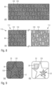
- the security element 20 When viewed in visible light, the security element 20 appears to the naked eye from a usual viewing distance of approximately 30 cm as a homogeneous surface 22 with a uniform color, for example red. As in detail D of the Fig. 2(a) illustrated, the surface that appears monochromatic is actually formed from a large number of small microstructure elements 24, 26, all of which have a dimension below the resolution limit of the human eye and are therefore not visible to the naked eye.
- the microstructure elements are formed by 80 ⁇ m ⁇ 80 ⁇ m squares 24, 26, each of which has a recess 28 in the form of letters or numbers, as in Fig. 2(a) illustrated by the letters “A” and “B” respectively.
- the squares 24 are printed directly onto the banknote paper of a banknote 10 with a printing ink with yellow color pigments, the squares 26 with a printing ink with magenta color pigments.
- the background underneath the microstructures, for example the white banknote paper appears in the letter-shaped recesses 28.
- the different colored squares 24, 26 produce the mixed color red of the surface 22 through subtractive color mixing, the color saturation of the red color impression being able to be adjusted by the size of the recesses 28.
- Figure 2 shows the same size Squares 24, 26, but the microstructures can also have different sizes, for example in order to produce a mixed color of a desired color.
- the surface 22, which appears homogeneously monochrome from a normal viewing distance, actually consists of the different colored squares 24, 26 with their letter-shaped recesses 28 can be determined with a magnifying glass or a microscope and represents an authenticity feature of the security element 20 that is difficult to reproduce.
- the security element 20 When viewed under UV light, the security element 20 shows the in Fig. 2(b) Appearance shown with two motif-shaped luminescence areas 30, 32 located within the surface 22, which glow with different luminescence colors, for example orange and green. Both luminescence colors are different from the visible red color of the surface 22, so that the luminescence areas 30, 32 appear in a clearly contrasting manner even with the combination lighting of visible and UV light that is usually present.
- the luminescence areas 30, 32 are not recognizable; the same homogeneous, red appearance is visible in their surface areas as in the rest of the surface 22, so that the position of the luminescence areas in Fig. 2(a) is only indicated by dashed lines.
- the homogeneous appearing surface 22 forms the above-mentioned first color area and at the same time the feature area that is congruent with the first color area, and the luminescence areas 30, 32 together form the above-mentioned second color area, which overlaps the feature area.
- the second color area is the second color area arranged completely within the feature area.
- the microscopic microstructure elements 24, 26 and the macroscopic luminescence regions 30, 32 can advantageously be coordinated with one another.
- the recesses 28 of the microstructure elements 24, 26 can be designed alternately in the form of the numbers "1" and "0" of the value number "10" of the banknote, and the two luminescent areas 30, 32 can also be in the form of the numbers "1” or "0” may be applied to represent the value under UV lighting.
- Figure 3 shows in (a) schematically the structure of an unclaimed security element 20 in cross section, which Figures 3(b) and 3(c) illustrate the associated appearance of the security element when viewed in visible light or in UV light in top view.
- the security element 20 has a substrate 36, which in particular represents the substrate of the document of value onto which the security element 20 is applied, for example printed.
- the substrate 36 it is also possible for the substrate 36 to be a substrate film of a separate security element, which is applied, for example glued, to a desired target substrate after its production.
- the security element 20 can also have been produced on a transfer carrier substrate, transferred to the target substrate and the transfer carrier substrate then peeled off.
- the surface 22 is formed by a sequence of microstructure elements 24, 26, which are formed, for example, by printing inks with yellow or magenta color pigments.
- the microstructure elements can also contain recesses, as in Fig. 2 shown, but for the sake of easier presentation Fig. 3 are not shown.
- the microstructure elements can be applied adjacent to one another or at a small distance next to one another. Due to the small dimensions of the microstructure elements 24, 26, the surface 22 appears from a normal viewing distance with the uniform subtractive mixed color of the yellow and magenta microstructure elements, i.e. in a uniform red color.
- the printing inks of the microstructure elements 24, 26 in the first luminescence regions 30 are mixed with a first luminescent substance 40, which is transparent in the visible spectral range and therefore does not influence the visual colors of the microstructure elements.
- a second, visible transparent luminescent substance 42 is mixed into the printing inks of the microstructure elements 24, 26.
- the luminescent colors of the first and second luminescent substances 40, 42 differ from one another and also differ from the mixed color of the surface 22.
- the non-luminescent areas 34 the printing colors of the microstructure elements 24, 26 are present without the admixture of luminescent substances.
- the luminescence areas 30, 32 are formed macroscopically in the form of characters or patterns, such as the coat of arms motif or the star motif Fig. 2(b) .
- the luminescence regions have such large dimensions that, in contrast to the microstructure elements 24, 26, they can be seen with the naked eye from a normal viewing distance, and therefore each contain a large number of microstructure elements 24, 26.
- the Luminescence areas 30, 32 can be continuous or gridded, i.e. formed by small luminescent grid elements that cannot be resolved with the naked eye, which together form the desired luminescence motif from a normal viewing distance.
- Six different printing colors are therefore used to print the surface 22, namely the visually visible printing ink with the first color (yellow) without the addition of luminescent substance, the visually visible printing ink of the first color with the addition of the first luminescent substance 40 or the second luminescent substance 42 , the visually visible printing ink of the second color (magenta) without admixture of luminescent substance and the visually visible printing ink of the second color with admixture of the first luminescent substance 40 or the second luminescent substance 42.
- the transparent luminescent substances do not appear when viewed in the visible spectral range.
- the sequence of the different colored microstructure elements 24, 26 can be seen with a magnifying glass; with the naked eye, the color effects of the microstructure elements 24, 26 mix to form the uniform mixed color of the surface 22.
- the luminescent areas 30, 32 When viewed under UV light, the luminescent areas 30, 32 glow in the corresponding luminescent colors, as shown in Fig. 3(c) illustrated. In the case of a combination illumination of visible light and UV light, in addition to the luminescent colors, the colors of the microstructure elements 24, 26 also appear, so that the luminescent areas 30, 32 appear to the naked eye against the background of the mixed color of the surface 22.
- Figure 4 shows a modification of the design that falls under the main claim Fig. 3 , in which the luminescent substances 40, 42 are not mixed with the printing inks of the microstructure elements 24, 26, but are printed separately as visually transparent, luminescent printing inks 50, 52 on the printing layer with the microstructure elements 24, 26.
- the macroscopic luminescence regions 30, 32 fit to the microstructure elements 24, 26.
- the luminescence areas can be either continuous (illustrated on the luminescence area 30) or rasterized (illustrated on the luminescence area 32), i.e. formed by small luminescent grid elements 38 that cannot be resolved with the naked eye, which form the desired luminescence motif from the normal viewing distance in the manner of a raster image generate.
- the printing inks 50, 52 can be printed onto the microstructure elements 24, 26, as in Fig. 4 illustrated, or below the microstructure elements 24, 26 are available. In the latter case, the light emitted after UV excitation passes through the printing inks of the microstructure elements 24, 26, so that the perceptible luminescence colors result from the emitted luminescence colors and the absorption properties of the printing inks of the microstructure elements. It goes without saying that the luminescent printing inks 50, 52 can also be present partly above and partly below the microstructure elements 24, 26. The technological challenge of this design lies in particular in the fit of the microstructure elements 24, 26 to produce the homogeneously monochromatic surface 22.
- the visually invisible luminescent printing ink is printed more or less well registered in the area of the first visually visible microstructure color, for example yellow, and for the second luminescent area in the area of the second visually visible microstructure, for example magenta.
- the visually invisible luminescent printing ink is printed more or less well registered in the area of the first visually visible microstructure color, for example yellow, and for the second luminescent area in the area of the second visually visible microstructure, for example magenta.
- Figure 5 shows another unclaimed modification of the design of the Fig. 3 , in which one of the printing inks, in the exemplary embodiment the printing ink for the microstructure elements 24 ', is formulated to be opaque and these microstructure elements 24' are printed on previously applied microstructure elements 26'.
- the opaque printing ink of the microstructures 24' partially covers the microstructures 26' arranged underneath, so that essentially only the opaque printing ink appears at the overprinted areas.
- the printing ink provided with a luminescent substance 40 or 42 also has an opaque effect, only the luminescent substance of the opaque printing ink is excited to emit in the overprinted areas in the luminescent areas 30 and 32, respectively. Accordingly, the result is essentially an appearance as in Fig. 3(b) in visible light and an appearance like in Fig. 3(c) in UV light.
- Figure 6 shows another modification of the design that falls under the main claim Fig. 3 , in which there is a continuous luminescent layer 60 on the substrate 36, which takes up the entire surface 22 and contains a first luminescent substance 40 in some areas and a second luminescent substance 42 in some areas.
- the microstructure elements 24, 26 are printed onto the luminescent layer 60, with a UV blocker 62 being mixed into the printing inks of the microstructure elements 24, 26 in the non-luminescent areas 34, which prevents UV excitation of the luminescent substances 40, 42 at these points.
- the luminescent substances 40, 42 can be excited through the visible printing inks and the luminescence emission, filtered through the printing inks of the microstructure elements 24, 26, can be observed.
- the overall result is essentially an appearance as in Fig. 3(b) in visible light and an appearance like in Fig. 3(c) in UV light.
- areas of the luminescent layer 60 without overprinting by visually visible printing inks or in recesses of the visually visible printing inks there is no filtering of the emission color.
- IR-stimulable luminescent substances are used, corresponding NIR absorbers must be used instead of UV blockers in order to achieve the desired prevention of IR excitation.
- FIG. 7 shows schematically the structure of an unclaimed security element 20 in cross section and in (b) and (c) the associated appearance when viewed in visible light or in UV light in top view.
- surface 22 is referenced Fig. 7(a) formed by a sequence of microstructure elements 24, 26, which are applied to the substrate 36 with small gaps 70.
- the dimensions of the gaps 70 are of the same order of magnitude as the dimensions of the microstructure elements 24, 26.
- the gaps 70 are filled with visually transparent, luminescent printing inks 50, 52, which are filled with first and second luminescent substances 40, 42 are provided.
- the luminescent printing inks 50, 52 arranged there represent small printing dots or printing elements of a raster image, and form the desired motifs of the luminescent areas from a normal viewing distance, without the raster itself being resolvable with the naked eye.
- the luminescent areas 30, 32 When viewed under UV light, the luminescent areas 30, 32 light up in the corresponding luminescent colors, as shown in Fig. 7(c) illustrated, whereby the luminescent spaces produce the desired luminescence motifs in the manner of raster images as described.
- inventions described can also be used Figures 2 to 7 are possible and that more than two different visually visible colors and more than two different luminescent colors can be used to further complicate reenactment.
- the luminescent substances can differ from one another in particular in the excitation spectrum, the emission spectrum and the afterglow duration.
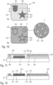
- Figure 8 illustrates some advantageous embodiments for dividing the visually homogeneous surface into microstructure elements in the form of various characters and symbols. An enlarged section of the area of the first color area with the microstructure elements is shown schematically. To the naked eye, the surface appears homogeneous from a normal viewing distance, as already explained above.
- the seemingly homogeneous surface 80 contains microstructure elements 82 of a first color, and microstructure elements 84 of a second, different color.
- the microstructure elements are each formed by letters of a specific font in the same font size and printed on a white substrate base 86.
- the line width of the letters is 10 ⁇ m to 30 ⁇ m and the letter height is 30 ⁇ m to 100 ⁇ m.
- the letters of the different colored microstructure elements 82, 84 form the word "TALER" as a hidden coding that is only visible with a magnifying glass.
- the color of the initial letter “T” changes constantly in order to create the most uniform color impression possible of the surface 80 from the normal viewing distance.
- the color of the surface 80 results from the two different colors of the microstructure elements 82, 84 and the white color of the substrate background 86.
- the color of the first letters of each line also advantageously changes from line to line in order to avoid monochrome edge lines.
- the exemplary embodiment of the Fig. 8(b) shows a modification of the design Fig. 8(a) , in which the readability of the microwriting formed by the microstructure elements is increased by adding a star-shaped separation symbol 88.
- the separator symbol 88 preferably has essentially the same area coverage as the letter symbols so as not to introduce any noticeable disturbances in the character string.
- the addition of the separation symbol 88 results in a further advantage that the color of the initial letter "T" can now always be the same, thereby increasing the readability of the coded word under a magnifying glass. It is understood that instead of the in Fig. 8(b) Others also used Stern symbols, and that multiple separation symbols can also be used.
- the surface is 80, as in the design of the Fig. 2 , formed by a sequence of square microstructure elements 92, 94 in two different colors, the squares each containing a centered recess 98 in the form of the letters of the coded word "TALER".
- the mixed color of the surface 80 results from the colors of the microstructure elements 92, 94 and the white color of the substrate background in the recesses 98.
- the homogeneous appearing surface 80 is formed on the one hand by a negative microstructure 102 of a first color and on the other hand by a positive microstructure 104 of a second color.
- the negative microstructure 102 contains recesses in the form of the letters of the word "TALER", while the positive microstructure 104 congruently contains the same letters in positive representation, which are each arranged in the recesses of the negative microstructure 102.
- the unprinted portion of the substrate is further reduced by such a combination of two positive/negative microstructures and high color strength is achieved.
- the first color area 110 of a security element can also contain several partial areas 112, 114 in which the homogeneously appearing surface 80 each appears with a different mixed color.
- a negative microstructure 102 of a first color and a positive microstructure 104 of a second color and in a second subregion 114 a negative microstructure 106 of a third color, combined with the positive microstructure 104 of the second color ( or a fourth color).
- the surface 80 then appears homogeneous and with a uniform color in both the partial area 112 and the partial area 114, the uniform color in the first partial area 114 being due to subtractive color mixing of the first and second colors, and the uniform color in the second partial area 116 by subtractive color mixing of the third and second colors (or the third and fourth colors).
- the color of the positive microstructure 104 can also change from the first to the second subregion.
- the partial areas of different colors can be spaced apart or directly adjacent to one another. More than two partial areas with different mixed colors can also be provided.
- the mixed colors of these several partial areas are coordinated with one another in such a way that, from the normal viewing distance, they appear as a quasi-continuous color gradient between two areas with fixed but different mixed colors.
- Figure 9 shows a further development of the security element 20 Figures 2 and 3 , in which the first color area 22 and the second color area 30, 32 are overprinted with a line structure 120, the color of which differs from the uniform red mixed color of the first color area.
- the structure 120 can also be created by leaving out the visually visible colors.
- the line structure 120 can be designed in any way but preferably takes up a geometric shape present in the partial areas 30, 32 or 34, in the exemplary embodiment approximately the star shape of the second luminescence area 32.
- the additional line structure 120 masks any noticeable color differences, gloss differences and/or registration fluctuations between the partial areas 30, 32 or 34, which can remain in some cases despite the basic color sameness and the visual transparency of the luminescent substances.
- the line structure 120 is printed with a visually visible, non-luminescent color so that when viewed in visible light it has the masking effect described, as in Fig. 9(a) illustrated. When viewed under UV light, the line structure 120 appears darker in the luminescence areas 30, 32 because it reduces the emission of the luminescent substances there. In Fig. 9(b) To illustrate this effect, this effect is shown with an exaggerated line thickness of the line structure 120 in the case of complete blocking of the luminescence emission.
- Figures 10 and 11 illustrate another design of a security element 200, where Fig. 10(a) the appearance of the security element 200 in visible light and Fig. 10(b) represents the appearance of the security element under UV light.
- Figure 11 shows schematically the structure of the security element 200 in cross section along the line XI-XI of Fig. 10(a) .
- the security element 200 appears in visible light with two or more different colors in an area 202, where in Fig. 10(a) To illustrate, two color areas 204, 206 of different colors are shown, which are separated by an unprinted intermediate area 208.
- the appearance of the security element 200 changes, so that when viewed with the naked eye from a usual viewing distance of approximately 30 cm, both color areas 204, 206 now glow in the same luminescent color, as in Fig. 10(b) illustrated.
- the two motifs 204 (coat of arms and star) can appear red against a blue background 206 in visible light, while under UV light both the two motifs 204 and the background 206 appear with yellow luminescence.
- the monochrome luminescent surface is actually composed of a plurality of small luminescent microstructure elements 224, 226, which have a dimension below the resolution limit of the human eye and are therefore not visible to the naked eye.
- the single-color luminescent surface 202 is formed by a negative microstructure 224 with a first luminescent color, for example red, and a positive microstructure 226 of a second luminescent color, for example green, which together produce the yellow luminescent color of the surface 202 through additive color mixing.
- the negative microstructure 224 contains the letters of the encoded word "TALER" as recesses, while the positive microstructure 226, congruent with the recesses of the negative microstructure 224, contains the same letters in positive representation.
- the security element 200 has a substrate 36, which, as in the previously described designs, can be, for example, a substrate film of the security element itself or the substrate of a document of value on which the security element is applied.
- the two different colored color areas 204, 206 are printed on the substrate 36 using visually visible printing inks.
- a luminescent layer 220 which is formed by the above-mentioned sequence of elements of the negative microstructure 224 and the positive microstructure 226, is applied to both color areas.
- the negative microstructure 224 contains a first luminescent substance 214, which luminesces red after UV excitation
- the positive microstructure 226 contains a second luminescent substance 216, which luminesces green after UV excitation. Due to the small dimensions of the microstructure elements 224, 226, the surface 202 appears with the uniform additive mixed color yellow from a normal viewing distance in UV light. With a magnifying glass or a microscope, the composite character of the area 202 can be proven as an authenticity feature.
- microstructure elements 224, 226 can also be applied in other arrangements, in particular in one of the above with reference to Figures 8(a) to 8(e) described arrangements.
- the luminescent substances 214, 216 can also each be mixed with a visually visible printing ink, as shown in FIG Fig. 12 illustrated.
- the luminescent substances 214 and 216 are each mixed with a blue printing ink in the color areas 206, and the two printing inks 234, 236 thus obtained are printed alternately in the form of the microstructure elements 224, 226 in order to produce the background area 206.
- the luminescent substances 214 and 216 are each mixed with a red printing ink, and the two printing inks 244, 246 thus obtained are printed alternately in the form of the microstructure elements 224, 226 in order to produce the red motif areas 204.
- the result of this variant also results in the appearance of the security element 200 described above.
- the exemplary embodiments were each described with reference to UV light as excitation radiation, but it is understood that luminescent substances that can be stimulated to luminescence by IR light can also be used in the same way.
Landscapes
- Business, Economics & Management (AREA)
- Accounting & Taxation (AREA)
- Finance (AREA)
- Printing Methods (AREA)
- Credit Cards Or The Like (AREA)
Description
Die Erfindung betrifft ein Sicherheitselement zur Absicherung von Wertgegenständen, einen Datenträger mit einem solchen Sicherheitselement, sowie ein Verfahren zum Herstellen eines solchen Sicherheitselements.The invention relates to a security element for securing valuables, a data carrier with such a security element, and a method for producing such a security element.
Datenträger, wie Wert- oder Ausweisdokumente, aber auch andere Wertgegenstände, wie etwa Markenartikel, werden zur Absicherung oft mit Sicherheitselementen versehen, die eine Überprüfung der Echtheit der Datenträger gestatten und die zugleich als Schutz vor unerlaubter Reproduktion dienen. In diesem Zusammenhang ist es bekannt, Lumineszenzstoffe zur Absicherung von Wert- oder Ausweisdokumenten einzusetzen. Das Vorliegen der Lumineszenzstoffe kann dann beispielsweise mit Hilfe einer UV-Lampe geprüft werden.Data carriers, such as valuables or identification documents, but also other valuables, such as branded items, are often provided with security elements for security purposes, which allow the authenticity of the data carrier to be checked and which also serve as protection against unauthorized reproduction. In this context, it is known to use luminescent substances to secure valuables or identification documents. The presence of the luminescent substances can then be checked, for example, using a UV lamp.
Seit einigen Jahren sind auf Grund des niedrigen Preises Tintenstrahldrucker leicht verfügbar, mit denen potentielle Fälscher Eindrucksfälschungen von Banknoten erzeugen können, die auf dem ersten Blick eine große Ähnlichkeit mit dem Original zeigen. Der Druck kann dabei ohne eine Beobachtung durch Dritte und ohne die Möglichkeit einer Rückverfolgung zu einer bestimmten Person erfolgen. Inzwischen sind vor allem durch den Onlinehandel auch Tintenstrahl-Fluoreszenzfarben relativ leicht verfügbar, so dass auch Lumineszenzmerkmale mit Hilfe von Tintenstrahldruckern nachgestellt werden können.In recent years, due to their low price, inkjet printers have become readily available, with which would-be counterfeiters can create impression counterfeits of banknotes that, at first glance, bear a close resemblance to the original. The printing can take place without observation by third parties and without the possibility of tracing back to a specific person. Inkjet fluorescent colors are now relatively easily available, especially through online retail, so that luminescence features can also be recreated using inkjet printers.
Das Dokument
Davon ausgehend liegt der Erfindung die Aufgabe zugrunde, Sicherheitselemente und Wertdokumente anzugeben, die neben einem attraktiven Erscheinungsbild eine hohe Fälschungssicherheit aufweisen und insbesondere gegen Nachstellungen mittels Office-Druckern, wie etwa mehrfarbigen Tintenstrahldruckern geschützt sind.Proceeding from this, the invention is based on the object of providing security elements and valuable documents which, in addition to an attractive appearance, have a high level of security against forgery and are protected in particular against counterfeiting using office printers, such as multi-color inkjet printers.
Diese Aufgabe wird durch die Merkmale der unabhängigen Ansprüche gelöst. Weiterbildungen der Erfindung sind Gegenstand der abhängigen Ansprüche.This task is solved by the features of the independent claims. Further developments of the invention are the subject of the dependent claims.
Die Erfindung enthält ein Sicherheitselement nach Anspruch 1.The invention contains a security element according to claim 1.
Wie weiter unten genauer erläutert, kann der erste Farbbereich dabei mit seiner Form ein visuell sichtbares Motiv innerhalb eines andersfarbigen Umfelds zeigen. Bei Betrachtung unter UV- oder IR-Anregungslicht zeigt der Merkmalsbereich zumindest zwei verschiedene Lumineszenzfarben.As explained in more detail below, the shape of the first color area can show a visually visible motif within a different colored environment. When viewed under UV or IR excitation light, the feature area shows at least two different luminescence colors.
Der Begriff Lumineszenz umfasst dabei Phosphoreszenz und Fluoreszenz, wobei die Anregung der Lumineszenz mit nicht sichtbarer UV-Strahlung oder IR-Strahlung erfolgen kann. Die Lumineszenzstoffe sind vorzugsweise im sichtbaren Spektralbereich transparent.The term luminescence includes phosphorescence and fluorescence, with the excitation of luminescence using invisible UV radiation or IR radiation can occur. The luminescent substances are preferably transparent in the visible spectral range.
Ein homogenes Erscheinungsbild bei Betrachtung mit bloßem Auge bedeutet dabei insbesondere, dass der Betrachter aus einem normalen Betrachtungsabstand von 25 cm oder mehr keine Strukturen erkennen kann, sondern dass der erste Farbbereich den Eindruck einer gleichmäßig gedruckten Fläche erzeugt. Die Farbe des ersten Farbbereichs des Merkmalsbereichs ist dabei zumindest bereichsweise jeweils einheitlich, vorzugsweise zeigt der erste Farbbereich sogar nur eine einzige einheitliche sichtbare Farbe.A homogeneous appearance when viewed with the naked eye means in particular that the viewer cannot see any structures from a normal viewing distance of 25 cm or more, but that the first color area creates the impression of a uniformly printed area. The color of the first color range of the feature range is uniform at least in some areas; the first color range preferably even shows only a single, uniform visible color.
Mit Vorteil liegen zumindest zwei Lumineszenzstoffe des zweiten Farbbereichs, die zwei verschiedene Lumineszenzfarben erzeugen, vollständig innerhalb eines Bereichs des ersten Farbbereichs mit einer einheitlichen sichtbaren Farbe.Advantageously, at least two luminescent substances of the second color range, which produce two different luminescent colors, lie completely within a region of the first color range with a uniform visible color.
Die durch Anregung erzeugten Lumineszenzfarben des Merkmalsbereichs unterscheiden sich vorzugsweise von den jeweils einheitlichen sichtbaren Farben des Merkmalsbereichs, insbesondere unterscheiden sie sich im Fall einer einzigen einheitlichen sichtbaren Farbe von dieser.The luminescence colors of the feature area generated by excitation preferably differ from the respective uniform visible colors of the feature area, in particular they differ from this in the case of a single uniform visible color.
Der zweite Farbbereich weist vorteilhaft zwei oder mehr Lumineszenzbereiche auf, die in Form von Mustern, Zeichen oder Codierungen ausgebildet sind und die unter UV- oder IR-Anregungslicht jeweils eine der verschiedenen Lumineszenzfarben zeigen. Der zweite Farbbereich kann vollständig innerhalb des Merkmalsbereichs angeordnet sein und nur einen Teil des Merkmalsbereichs bedecken. Es ist allerdings auch möglich, dass der zweite Farbbereich den Merkmalsbereich vollständig bedeckt und/oder dass der zweite Farbbereich teilweise auch außerhalb des Merkmalbereichs liegt. In einer vorteilhaften Ausgestaltung liegt der zweite Farbbereich vollständig innerhalb des ersten Farbbereichs.The second color area advantageously has two or more luminescence areas which are designed in the form of patterns, characters or codes and which each show one of the different luminescence colors under UV or IR excitation light. The second color area may be located entirely within the feature area and cover only a portion of the feature area. However, it is also possible for the second color range to completely cover the feature range and/or for the second color range to also lie partially outside the feature range. In In an advantageous embodiment, the second color range lies completely within the first color range.
Die Mikrostrukturelemente weisen zwei oder mehr unterschiedliche Farben auf, die aus dem normalen Betrachtungsabstand durch Farbmischung, insbesondere subtraktive Farbmischung, den wahrzunehmenden Farbeindruck für den Betrachter erzeugen. Neben den Farben der Mikrostrukturelemente kann auch eine Hintergrundfarbe, beispielsweise die Farbe des Trägers, auf dem die Mikrostrukturelemente aufgebracht sind, zu der Mischfarbe beitragen. Insbesondere bei Papiersubstraten ist diese Hintergrundfarbe oft Weiß, sie kann aber auch durch eine farbige Unterdruckschicht bereitgestellt sein. Die Hintergrundfarbe kann insbesondere in Zwischenräumen zwischen den Mikrostrukturelementen und/oder in Aussparungen der Mikrostrukturelemente vorliegen und zur Mischfarbe beitragen.The microstructure elements have two or more different colors, which produce the perceived color impression for the viewer from the normal viewing distance through color mixing, in particular subtractive color mixing. In addition to the colors of the microstructure elements, a background color, for example the color of the carrier on which the microstructure elements are applied, can also contribute to the mixed color. In the case of paper substrates in particular, this background color is often white, but it can also be provided by a colored underprint layer. The background color can be present in particular in spaces between the microstructure elements and/or in recesses in the microstructure elements and contribute to the mixed color.
Mit Vorteil ist vorgesehen, dass die unterschiedlichen Farben der Mikrostrukturelemente im CIELab-System einen Farbunterschied ΔE von zumindest 4,0, vorzugsweise von zumindest 6,0 aufweisen. Der Farbunterschied ΔE ist dabei ein Maß für den empfundenen Farbabstand und ist so konstruiert, dass er für alle auftretenden Farben im Wesentlichen gleichabständig ist. Werden zwei Farben F1 und F2 durch ihre Koordinaten F1 = (L1*, a1*, b1*) bzw. F2 = (L2*, a2*, b2*) im CIELab-Farbraum angegeben, so ist der genannte Farbunterschied durch ![]()
![]()
Die Mikrostrukturelemente des ersten Farbbereichs können aneinander angrenzend oder auch beabstandet nebeneinander angeordnet sein. Die Mikrostrukturelemente können in Positivdarstellung in Form geometrischer Symbole, Buchstaben und/ oder Ziffern und/oder in Negativdarstellung als Fläche mit Aussparungen in Form geometrischer Symbole, Buchstaben und/ oder Ziffern ausgebildet sein. Als geometrische Symbole kommen dabei insbesondere Linienbruchstücke, Quadrate, Dreiecke oder andere Polygone, jeweils mit oder ohne Füllung in Betracht. Mit Vorteil nehmen die Mikrostrukturelemente zumindest teilweise geometrische Elemente auf, die an anderer Stelle im Sicherheitselement mit bloßem Auge erkennbar sind, um einen Zusammenhang zwischen den verschiedenen Elementen des Sicherheitselements herzustellen. Ein solcher Zusammenhang erleichtert auch die Erkennung oder Identifizierung des Inhalts einer von der Mikrostruktur codierten Information.The microstructure elements of the first color range can be arranged adjacent to one another or at a distance from one another. The microstructure elements can be shown in positive form in the form of geometric symbols, Letters and/or numbers and/or in negative representation as a surface with recesses in the form of geometric symbols, letters and/or numbers. In particular, line fragments, squares, triangles or other polygons, each with or without filling, come into consideration as geometric symbols. Advantageously, the microstructure elements at least partially accommodate geometric elements that are visible to the naked eye elsewhere in the security element in order to establish a connection between the various elements of the security element. Such a connection also makes it easier to recognize or identify the content of information encoded by the microstructure.
Die charakteristische Abmessung der Mikrostrukturelemente ist beispielsweise durch den Durchmesser der geometrischen Symbole oder die Strichstärke von Buchstaben oder Ziffern gegeben. Bei Negativdarstellungen bildet der Abstand benachbarter Aussparungen eine charakteristische Abmessung der Mikrostrukturelemente. Unabhängig von der konkreten Ausbildung der Mikrostrukturanordnung ist vorliegend allerdings nur wesentlich, dass die Mikrostrukturelemente aufgrund ihrer kleinen Abmessungen aus dem normalen Betrachtungsabstand von 25 cm oder mehr mit bloßem Auge nicht als solche erkennbar sind, sondern dass die Mikrostrukturanordnung durch die Farbmischung der Elementfarben wie bei einem feinen Druckraster als homogene Fläche wahrgenommen wird.The characteristic dimensions of the microstructure elements are given, for example, by the diameter of the geometric symbols or the line thickness of letters or numbers. In negative representations, the distance between adjacent recesses forms a characteristic dimension of the microstructure elements. Regardless of the specific design of the microstructure arrangement, the only important thing in the present case is that the microstructure elements cannot be recognized as such with the naked eye due to their small dimensions from the normal viewing distance of 25 cm or more, but that the microstructure arrangement is due to the color mixing of the element colors like a fine print grid is perceived as a homogeneous surface.
In einer vorteilhaften Ausgestaltung enthalten die Mikrostrukturelemente eine erste Gruppe von Mikrostrukturelementen einer ersten Farbe in Negativdarstellung und eine zweite Gruppe von Mikrostrukturelementen einer zweiten, unterschiedlichen Farbe in Positivdarstellung, wobei die Mikrostrukturelemente der zweiten Gruppe in den Aussparungen der ersten Gruppe von Mikrostrukturelementen angeordnet sind.In an advantageous embodiment, the microstructure elements contain a first group of microstructure elements of a first color in a negative representation and a second group of microstructure elements of a second, different color in a positive representation, the microstructure elements of the second group are arranged in the recesses of the first group of microstructure elements.
Die Lumineszenzstoffe des zweiten Farbbereichs liegen zumindest bereichsweise in einer oberhalb und/ oder unterhalb der visuell sichtbaren Druckfarben angeordneten Lumineszenzschicht vor.The luminescent substances of the second color range are present at least in some areas in a luminescent layer arranged above and/or below the visually visible printing inks.
Bei einer weiteren vorteilhaften Ausgestaltung liegen die Lumineszenzstoffe des zweiten Farbbereichs in einer unterhalb der visuell sichtbaren Druckfarben angeordneten Lumineszenzschicht vor und die visuell sichtbaren Druckfarben des ersten Farbbereichs enthalten bereichsweise einen UV-Blocker, der eine UV-Anregung zumindest in einem Teilbereich des UV-Spektrums zwischen 200 nm und 400 nm reduziert oder verhindert.In a further advantageous embodiment, the luminescent substances of the second color range are present in a luminescence layer arranged below the visually visible printing inks and the visually visible printing inks of the first color range contain a UV blocker in some areas, which prevents UV excitation at least in a partial range of the
In einer Weiterbildung der Erfindung ist vorgesehen, dass der erste und zweite Farbbereich mit einer Linienstruktur mit einer nicht-lumineszierenden, visuell sichtbaren Farbe überdruckt sind, deren Farbe sich von der oder den einheitlichen Farben des ersten Farbbereichs unterscheidet. Die Linienstruktur nimmt vorzugsweise an anderer Stelle im Sicherheitselement mit bloßem Auge erkennbare geometrische Formen, insbesondere die Umrissform eines lumineszierenden oder nicht-lumineszierenden Teilbereichs des Merkmalbereichs auf. Mit der zusätzlichen Linienstruktur können eventuell sichtbare Farbunterschiede, Glanzunterschiede und/ oder Passerschwankungen der visuell sichtbaren Druckfarben maskiert werden.In a further development of the invention it is provided that the first and second color ranges are overprinted with a line structure with a non-luminescent, visually visible color, the color of which differs from the uniform color or colors of the first color range. The line structure preferably accommodates geometric shapes that can be seen with the naked eye elsewhere in the security element, in particular the outline shape of a luminescent or non-luminescent partial area of the feature area. With the additional line structure you can Any visible color differences, gloss differences and/or registration fluctuations of the visually visible printing inks are masked.
Bei einer visuell sehr attraktiven Gestaltung weisen die mindestens zwei verschiedenen makroskopischen Lumineszenzbereiche eine andersfarbige lumineszierende Außenkontur auf, welche im Farbton der jeweils anderen Lumineszenzfarbe oder einer Mischfarbe der beiden Lumineszenzfarben entspricht.In a visually very attractive design, the at least two different macroscopic luminescence areas have a different colored luminescent outer contour, which corresponds in color to the other luminescence color or a mixed color of the two luminescence colors.
Die Mikrostrukturanordnung ist vorteilhaft auf einem transparenten oder opaken Träger, insbesondere auf einem Transferfolienelement angeordnet. Die Mikrostrukturanordnung kann dabei insbesondere direkt auf dem Träger angeordnet, insbesondere auf den Träger aufgedruckt sein.The microstructure arrangement is advantageously arranged on a transparent or opaque carrier, in particular on a transfer film element. The microstructure arrangement can in particular be arranged directly on the carrier, in particular printed onto the carrier.
Das Sicherheitselement ist mit Vorteil ein Sicherheitsfaden, insbesondere ein Fenstersicherheitsfaden oder ein Pendelsicherheitsfaden, ein Aufreißfaden, ein Sicherheitsband, ein Sicherheitsstreifen, ein Patch oder ein Etikett zum Aufbringen auf ein Sicherheitspapier, Wertdokument oder dergleichen. Das Sicherheitselement kann dabei eine Trägerfolie enthalten oder ohne Trägerfolie vorliegen.The security element is advantageously a security thread, in particular a window security thread or a pendulum security thread, a tear thread, a security tape, a security strip, a patch or a label for application to a security paper, document of value or the like. The security element can contain a carrier film or be present without a carrier film.
Die Erfindung enthält auch ein Verfahren zur Herstellung eines Sicherheitselements der beschriebenen Art nach Anspruch 14.The invention also contains a method for producing a security element of the type described according to claim 14.
Mit Vorteil werden bei dem Verfahren die Mikrostrukturanordnung und/ oder die Lumineszenzstoffe im Offsetdruck, Hochdruck, indirekten Hochdruck, Tiefdruck oder in einem Digitaldruckverfahren wie Ink-Jet-Druck oder Laserdruckverfahren aufgebracht.In the process, the microstructure arrangement and/or the luminescent substances are advantageously applied in offset printing, letterpress printing, indirect letterpress printing, gravure printing or in a digital printing process such as ink-jet printing or laser printing process.
In einem anderen, nicht beanspruchten Aspekt enthält die Beschreibung ein Sicherheitselement zur Absicherung von Wertgegenständen bereit, mit
- einem Merkmalsbereich, der einen ersten Farbbereich enthält, der aus visuell sichtbaren Druckfarben gebildet ist,
- einem zweiten Farbbereich, der aus ohne Anregung nicht sichtbaren Lumineszenzstoffen gebildet ist und der den Merkmalsbereich zumindest teilweise überlappt,
- der Merkmalsbereich bei Betrachtung im sichtbaren Licht zumindest zwei verschiedene sichtbare Farben zeigt,
- der zweite Farbbereich des Merkmalsbereichs bei Betrachtung mit bloßem Auge unter UV- oder IR-Anregungslicht ein homogenes Erscheinungsbild mit einer zumindest bereichsweise jeweils einheitlichen Lumineszenzfarbe zeigt und
- wobei der zweite Farbbereich eine Mikrostrukturanordnung aus verschiedenfarbig lumineszierenden Mikrostrukturelementen enthält, die eine charakteristische Abmessung unterhalb der Auflösungsgrenze des menschliche Auges aufweisen und die jeweils eine von zumindest zwei unterschiedlichen Lumineszenzfarben aufweisen und durch Farbmischung die zumindest bereichsweise jeweils mit bloßem Auge sichtbare, einheitlichen Lumineszenzfarbe erzeugen.
- a feature area that contains a first color area that is formed from visually visible printing inks,
- a second color area which is formed from luminescent substances that are not visible without excitation and which at least partially overlaps the feature area,
- the feature area shows at least two different visible colors when viewed in visible light,
- the second color range of the feature area has a homogeneous appearance when viewed with the naked eye under UV or IR excitation light with a luminescence color that is uniform at least in some areas and
- wherein the second color range contains a microstructure arrangement of differently colored luminescent microstructure elements, which have a characteristic dimension below the resolution limit of the human eye and which each have one of at least two different luminescence colors and, by color mixing, produce the uniform luminescence color that is visible to the naked eye at least in some areas.
Vorzugsweise zeigt der zweite Farbbereich sogar nur eine einzige einheitliche Lumineszenzfarbe. Die bei Anregung erzeugten jeweils einheitlichen Lumineszenzfarben des Merkmalsbereichs, bzw. die einzige einheitliche Lumineszenzfarbe, unterscheiden sich vorteilhaft von den im sichtbaren Licht sichtbaren Farben des Merkmalsbereichs.Preferably, the second color range even shows only a single uniform luminescence color. The uniform luminescence colors of the feature area generated upon excitation, or the only uniform luminescence color, advantageously differ from the colors of the feature area that are visible in visible light.
Der erste Farbbereich weist vorteilhaft zwei oder mehr Farbbereiche auf, die in Form von Mustern, Zeichen oder eine Codierung ausgebildet sind und die im sichtbaren Licht jeweils eine der verschiedenen sichtbaren Farben zeigen.The first color range advantageously has two or more color ranges, which are designed in the form of patterns, characters or a coding and which each show one of the different visible colors in visible light.
Die Mikrostrukturelemente weisen zwei oder mehr unterschiedliche Lumineszenzfarben auf, die aus dem normalen Betrachtungsabstand durch Farbmischung, insbesondere additive Farbmischung und Absorption der Emissionsfarbe durch die visuell sichtbaren Farben, den wahrzunehmenden Farbeindruck für den Betrachter erzeugen. Neben den Farben der Mikrostrukturelemente kann auch eine lumineszierende Hintergrundfarbe zu der Mischfarbe beitragen. Mit Vorteil ist vorgesehen, dass die unterschiedlichen Lumineszenzfarben der Mikrostrukturelemente im CIELab- System einen Farbunterschied ΔE von zumindest 4,0, vorzugsweise von zumindest 6,0 aufweisen.The microstructure elements have two or more different luminescent colors, which produce the perceived color impression for the viewer from the normal viewing distance through color mixing, in particular additive color mixing and absorption of the emission color by the visually visible colors. In addition to the colors of the microstructure elements, a luminescent background color can also contribute to the mixed color. It is advantageously provided that the different luminescence colors of the microstructure elements in the CIELab system have a color difference ΔE of at least 4.0, preferably of at least 6.0.
Analog zum ersten Erfindungsaspekt können die Mikrostrukturelemente des zweiten Farbbereichs aneinander angrenzend oder auch beabstandet nebeneinander angeordnet sein. Die Mikrostrukturelemente können in Positivdarstellung in Form geometrischer Symbole, Buchstaben und/ oder Ziffern und/ oder in Negativdarstellung als Fläche mit Aussparungen in Form geometrischer Symbole, Buchstaben und/oder Ziffern ausgebildet sein. Als geometrische Symbole kommen dabei insbesondere Linienbruchstücke, Quadrate, Dreiecke oder andere Polygone, jeweils mit oder ohne Füllung in Betracht. Mit Vorteil nehmen die Mikrostrukturelemente zumindest teilweise geometrische Elemente auf, die an anderer Stelle im Sicherheitselement mit bloßem Auge erkennbar sind, um einen Zusammenhang zwischen den verschiedenen Elementen des Sicherheitselements herzustellen. Ein solcher Zusammenhang erleichtert auch die Erkennung oder Identifizierung des Inhalts einer von der Mikrostruktur codierten Information.Analogous to the first aspect of the invention, the microstructure elements of the second color range can be arranged adjacent to one another or at a distance from one another. The microstructure elements can be designed in the positive representation in the form of geometric symbols, letters and/or numbers and/or in the negative representation as a surface with recesses in the form of geometric symbols, letters and/or numbers. In particular, line fragments, squares, triangles or other polygons, each with or without filling, come into consideration as geometric symbols. Advantageously, the microstructure elements at least partially accommodate geometric elements that are visible to the naked eye elsewhere in the security element in order to establish a connection between the various elements of the security element. Such a connection also makes it easier to recognize or identify the content of information encoded by the microstructure.
Die charakteristische Abmessung der Mikrostrukturelemente ist beispielsweise durch den Durchmesser der geometrischen Symbole oder die Strichstärke von Buchstaben oder Ziffern gegeben. Bei Negativdarstellungen bildet der Abstand benachbarter Aussparungen eine charakteristische Abmessung der Mikrostrukturelemente. Unabhängig von der konkreten Ausbildung der Mikrostrukturanordnung ist vorliegend allerdings nur wesentlich, dass die Mikrostrukturelemente aufgrund ihrer kleinen Abmessungen aus dem normalen Betrachtungsabstand von 25 cm oder mehr also solche mit bloßem Auge nicht erkennbar sind, sondern dass die Mikrostrukturanordnung durch die additive Farbmischung der Lumineszenzfarben der Elemente wie bei einem feinen Druckraster als homogene Fläche wahrgenommen wird.The characteristic dimensions of the microstructure elements are given, for example, by the diameter of the geometric symbols or the line thickness of letters or numbers. In negative representations, the distance between adjacent recesses forms a characteristic dimension of the microstructure elements. Regardless of the specific design of the microstructure arrangement, the only important thing in the present case is that the microstructure elements cannot be seen with the naked eye due to their small dimensions from the normal viewing distance of 25 cm or more, but that the microstructure arrangement is created by the additive color mixing of the luminescent colors of the elements like a fine print screen is perceived as a homogeneous surface.
In einer vorteilhaften Ausgestaltung enthalten die Mikrostrukturelemente eine erste Gruppe von Mikrostrukturelementen einer ersten Lumineszenzfarbe in Negativdarstellung und eine zweite Gruppe von Mikrostrukturelementen einer zweiten, unterschiedlichen Lumineszenzfarbe in Positivdarstellung, wobei die Mikrostrukturelemente der zweiten Gruppe in den Aussparungen der ersten Gruppe von Mikrostrukturelementen angeordnet sind.In an advantageous embodiment, the microstructure elements contain a first group of microstructure elements of a first luminescent color in a negative representation and a second group of microstructure elements of a second, different luminescence color in a positive representation, the microstructure elements of the second group being arranged in the recesses of the first group of microstructure elements.
Die Lumineszenzstoffe des zweiten Farbbereichs sind in einer vorteilhaften Ausgestaltung zumindest bereichsweise den visuell sichtbaren Druckfarben des ersten Farbbereichs beigemischt und bilden dadurch Druckfarben, die sowohl visuell sichtbar als auch lumineszierend sind.In an advantageous embodiment, the luminescent substances of the second color range are mixed at least in areas with the visually visible printing inks of the first color range and thereby form printing inks that are both visually visible and luminescent.
Die Lumineszenzstoffe des zweiten Farbbereichs können in einer anderen, ebenfalls vorteilhaften Ausgestaltung zumindest bereichsweise in einer oberhalb und/ oder unterhalb der visuell sichtbaren Druckfarben angeordneten Lumineszenzschicht vorliegen.In another, also advantageous embodiment, the luminescent substances of the second color range can be present at least in some areas in a luminescent layer arranged above and/or below the visually visible printing inks.
Die Erfindung enthält auch einen Datenträger mit einem Sicherheitselement der beschriebenen Art. Bei dem Datenträger kann es sich insbesondere um ein Wertdokument, wie eine Banknote, insbesondere eine Papierbanknote, eine Polymerbanknote oder eine Folienverbundbanknote, um eine Aktie, eine Anleihe, eine Urkunde, einen Gutschein, einen Scheck, ein Sigel, eine Steuerbanderole, eine hochwertige Eintrittskarte, aber auch um eine Ausweiskarte, wie etwa eine Kreditkarte, eine Bankkarte, eine Barzahlungskarte, eine Berechtigungskarte, einen Personalausweis oder eine Passpersonalisierungsseite handeln.The invention also contains a data carrier with a security element of the type described. The data carrier can in particular be a document of value, such as a banknote, in particular a paper banknote, a polymer banknote or a film composite banknote, a share, a bond, a certificate, a voucher , a check, a seal, a tax stamp, a high-quality admission ticket, but also an identification card, such as a credit card, a bank card, a cash payment card, an authorization card, an ID card or a passport personalization page.
Das Sicherheitselement kann ein separates Sicherheitselement, beispielsweise ein Folienelement darstellen, das an einer gewünschten Stelle auf einem Datenträger angeordnet ist. Das Sicherheitselement kann mit besonderem Vorteil auch einen integralen Bestandteil des Datenträgers selbst bilden beispielsweise durch einen Aufdruck gebildet sein, der auf ein Substrat des Datenträgers aufgebracht ist.The security element can represent a separate security element, for example a film element, which is located at a desired location on a Disk is arranged. With particular advantage, the security element can also form an integral part of the data carrier itself, for example by means of an imprint that is applied to a substrate of the data carrier.
Weitere Ausführungsbeispiele sowie Vorteile der Erfindung werden nachfolgend anhand der Figuren erläutert, bei deren Darstellung auf eine maßstabs- und proportionsgetreue Wiedergabe verzichtet wurde, um die Anschaulichkeit zu erhöhen.Further exemplary embodiments and advantages of the invention are explained below with reference to the figures, which were not reproduced to scale and proportions in order to increase clarity.
Es zeigen:
- Fig. 1
- eine schematische Darstellung einer Banknote mit einem eingebetteten Sicherheitsfaden und zwei drucktechnisch erzeugten Sicherheitselementen, jeweils nach Ausführungsbeispielen der Erfindung,
- Fig. 2
- eine Aufsicht auf ein Sicherheitselement nach einem ersten Ausführungsbeispiel der Erfindung, wobei (a) das Erscheinungsbild des Sicherheitselements im sichtbaren Licht und (b) das Erscheinungsbild unter UV-Licht zeigt,
- Fig. 3
- in (a) schematisch den Aufbau eines nicht beanspruchten Sicherheitselements im Querschnitt, in (b) das zugehörige Erscheinungsbild bei Betrachtung im sichtbaren Licht und in (c) das Erscheinungsbild im UV-Licht in Aufsicht,
- Fig. 4 bis 6
- vorteilhafte Abwandlungen der Gestaltung der
Fig. 3 , wobei die Gestaltungen derFig. 4 und6 anspruchsgemäß sind und die Gestaltung derFig. 5 nicht beansprucht ist, - Fig. 7
- ein Sicherheitselement nach einer weiteren nicht beanspruchten Abwandlung der Gestaltung der
Fig. 3 , wobei (a) schematisch den Aufbau eines Sicherheitselements im Querschnitt zeigt und (b) und (c) das zugehörige Erscheinungsbild bei Betrachtung im sichtbaren Licht bzw. im UV-Licht in Aufsicht zeigen, - Fig. 8
- in (a) bis (e) vorteilhafte Ausgestaltungen der Aufteilung der visuell homogen erscheinenden Fläche erfindungsgemäßer Sicherheitselement in Mikrostrukturelemente,
- Fig. 9
- eine Weiterbildung des Sicherheitselements der
Fig. 2 , mit einer den ersten und zweiten Farbbereich überdruckenden Linienstruktur, wobei (a) das Erscheinungsbild des Sicherheitselements im sichtbaren Licht und (b) das Erscheinungsbild unter UV-Licht in Aufsicht zeigt, - Fig. 10
- ein Sicherheitselement nach einem anderen Aspekt, wobei (a) das Erscheinungsbild des Sicherheitselements im sichtbaren Licht und (b) das Erscheinungsbild unter UV-Licht in Aufsicht zeigt,
- Fig. 11
- schematisch den Aufbau des Sicherheitselements der
Fig. 10 im Querschnitt, und - Fig. 12
- eine nicht beanspruchte Abwandlung der Gestaltung der
Fig. 11 .
- Fig. 1
- a schematic representation of a banknote with an embedded security thread and two security elements produced by printing, each according to exemplary embodiments of the invention,
- Fig. 2
- a top view of a security element according to a first embodiment of the invention, wherein (a) shows the appearance of the security element in visible light and (b) shows the appearance under UV light,
- Fig. 3
- in (a) schematically the structure of an unclaimed security element in cross section, in (b) the associated appearance when viewed in visible light and in (c) the appearance in UV light in top view,
- Fig. 4 to 6
- advantageous modifications to the design of the
Fig. 3 , whereby the designs of theFig. 4 and6 are required and the design of theFig. 5 is not claimed, - Fig. 7
- a security element according to a further unclaimed modification of the design
Fig. 3 , where (a) shows schematically the structure of a security element in cross section and (b) and (c) show the associated appearance when viewed in visible light or in UV light in top view, - Fig. 8
- in (a) to (e) advantageous embodiments of the division of the visually homogeneous surface of the security element according to the invention into microstructure elements,
- Fig. 9
- a further development of the security element of the
Fig. 2 , with a line structure overprinting the first and second color areas, (a) showing the appearance of the security element in visible light and (b) showing the appearance under UV light in top view, - Fig. 10
- a security element according to another aspect, wherein (a) shows the appearance of the security element in visible light and (b) shows the appearance under UV light in top view,
- Fig. 11
- schematically the structure of the security element
Fig. 10 in cross section, and - Fig. 12
- an unclaimed modification of the design of the
Fig. 11 .
Die Erfindung wird nun am Beispiel von Sicherheitselementen für Banknoten erläutert.
Das zweite Sicherheitselement 16 ist durch einen Teilbereich der Banknote 10 gebildet, in dem das Banknotenpapier mit einem Aufdruck versehen ist, der die weiter unten genauer beschriebenen verschiedenen besonderen Farbbereiche aufweist. Das dritte Sicherheitselement 18 ist durch einen Teilbereich der Banknote 10 gebildet, in dem das Banknotenpapier mit einem motivförmigen Aufdruck, nämlich einen Aufdruck mit einer Aussparung in Form der Wertzahl "10" der Banknote, versehen ist. Auch dieser Aufdruck weist die nachfolgend beschriebenen besonderen Farbbereiche auf.The
Es versteht sich allerdings, dass die Erfindung nicht auf die in
Der Aufbau und das Erscheinungsbild erfindungsgemäßer Sicherheitselemente werden nun mit Bezug auf die nachfolgenden Figuren näher erläutert.The structure and appearance of security elements according to the invention will now be explained in more detail with reference to the following figures.
Bei der Betrachtung im sichtbaren Licht erscheint das Sicherheitselement 20 mit bloßem Auge aus einem üblichen Betrachtungsabstand von etwa 30 cm als homogene Fläche 22 mit einer einheitlichen Farbe, beispielsweise Rot. Wie im Detailausschnitt D der
Im Ausführungsbeispiel sind die Mikrostrukturelemente durch 80 µm × 80 µm große Quadrate 24, 26 gebildet, die jeweils eine Aussparung 28 in Form von Buchstaben oder Ziffern aufweisen, wie in
Die Tatsache, dass die aus normalem Betrachtungsabstand homogen einfarbig erscheinende Fläche 22 tatsächlich aus den verschiedenfarbigen Quadraten 24, 26 mit ihren buchstabenförmigen Aussparungen 28 besteht, kann mit einer Lupe oder einem Mikroskop festgestellt werden und stellt ein schwer nachzustellendes Echtheitsmerkmal des Sicherheitselements 20 dar.The fact that the
Bei Betrachtung unter UV-Licht zeigt das Sicherheitselement 20 das in
Im Ausführungsbeispiel der
Die mikroskopischen Mikrostrukturelemente 24, 26 und die makroskopischen Lumineszenzbereiche 30, 32 können vorteilhaft aufeinander abgestimmt sein. Beispielsweise können die Aussparungen 28 der Mikrostrukturelemente 24, 26 alternierend in Form der Ziffern "1" und "0" der Wertzahl "10" der Banknote ausgebildet sein, und die beiden Lumineszenzbereiche 30, 32 können ebenfalls in Form der Ziffern "1" bzw. "0" aufgebracht sein, um die Wertzahl bei UV-Beleuchtung darzustellen. Durch den Bezug der mikroskopischen und der makroskopischen Information aufeinander, wird eine zusätzliche Absicherungswirkung erreicht.The
Mit Bezug zunächst auf den Querschnitt der
Die Fläche 22 ist durch eine Abfolge von Mikrostrukturelementen 24, 26 gebildet, die beispielsweise durch Druckfarben mit gelben bzw. magentafarbenen Farbpigmenten gebildet sind. Die Mikrostrukturelemente können auch Aussparungen enthalten, wie in
Wie in
Die Lumineszenzbereiche 30, 32 sind makroskopisch in Form von Zeichen oder Mustern gebildet, wie etwa dem Wappenmotiv oder dem Sternmotiv der
Für den Druck der Fläche 22 kommen somit sechs verschiedenen Druckfarben zum Einsatz, nämlich die visuell sichtbare Druckfarbe mit der ersten Farbe (gelb) ohne Beimischung von Lumineszenzstoff, die visuell sichtbare Druckfarbe der ersten Farbe mit Beimischung des ersten Lumineszenzstoffs 40 bzw. des zweiten Lumineszenzstoffs 42, die visuell sichtbare Druckfarbe der zweiten Farbe (magenta) ohne Beimischung von Lumineszenzstoff und die visuell sichtbare Druckfarbe der zweiten Farbe mit Beimischung des ersten Lumineszenzstoffs 40 bzw. des zweiten Lumineszenzstoffs 42.Six different printing colors are therefore used to print the
Die Passerung dieser sechs Druckfarben stellte eine hohe Hürde für potentielle Fälscher dar und ist mit herkömmlichen Office-Druckern nicht zu erreichen. Herkömmliche Tintenstrahldrucker sind nämlich optimiert um farbige Bilder, wie etwa Fotos, möglichst gut wiederzugeben und verwenden zur Darstellung gleichmäßiger Farbverläufe und farbrichtiger Darstellungen daher eine spezielle Rastertechnologie. Bei dieser werden die farbigen Druckstrukturen aus leicht gegeneinander versetzten einzelnen Punkten zusammengesetzt und zeigen daher keine glatten Kanten. Sollen visuell sichtbare Farben zusätzlich eine Fluoreszenz zeigen, so muss dies mit einem zweiten Drucker, welcher mit fluoreszierenden Ink-Jet-Tinten bestückt ist, in einem weiteren Druckschritt erfolgen. Dabei kommt es bedingt durch das erneute Anlegen des mit den visuell sichtbaren Farben bedruckten Blattes durch Anlage- und Transporttoleranzen des Druckers unvermeidlich zu einem gewissen Versatz zwischen erstem und zweitem Druck.The registration of these six printing colors represented a high hurdle for potential counterfeiters and cannot be achieved with conventional office printers. Conventional inkjet printers are optimized to reproduce colored images, such as photos, as well as possible and therefore use a special raster technology to display uniform color gradients and color-correct representations. In this case, the colored print structures are composed of individual dots that are slightly offset from each other and therefore do not show any smooth edges. If visually visible colors are also to show fluorescence, this must be done in a further printing step using a second printer equipped with fluorescent ink-jet inks. Due to the re-application of the sheet printed with the visually visible colors, there is inevitably a certain offset between the first and second print due to the printer's system and transport tolerances.
Mit Bezug auf das visuelle Erscheinungsbild der
Bei Betrachtung unter UV-Licht leuchten die Lumineszenzbereiche 30, 32 in den entsprechenden Lumineszenzfarben, wie in
Die Druckfarben 50, 52 können dabei auf die Mikrostrukturelemente 24, 26 gedruckt werden, wie in
Verglichen mit der Ausgestaltung der
Bei einer prozesstechnisch anspruchsvolleren Variante wird die visuell nicht sichtbare Lumineszenzdruckfarbe einmal mehr oder weniger gut gepassert im Bereich der ersten visuell sichtbaren Mikrostrukturfarbe, beispielsweise Gelb, und für den zweiten lumineszierenden Bereich im Bereich der zweiten visuell sichtbaren Mikrostruktur, beispielsweise Magenta gedruckt. Bei Einsatz einer weißen Lumineszenzfarbe zeigt sich auf Grund der Wechselwirkung mit der Untergrundfarbe einmal ein gelb und einmal ein magenta farbenes LumineszenzbildIn a process-technically more sophisticated variant, the visually invisible luminescent printing ink is printed more or less well registered in the area of the first visually visible microstructure color, for example yellow, and for the second luminescent area in the area of the second visually visible microstructure, for example magenta. When using a white luminescence color, a yellow and a magenta luminescence image appears due to the interaction with the background color
Es ergibt sich daher insgesamt im Wesentlichen ein Erscheinungsbild wie in
Werden IR-anregbare Lumineszenzstoffe eingesetzt, so müssen anstelle der UV-Blocker entsprechende NIR-Absorber eingesetzt werden, um die gewünschte Verhinderung der IR-Anregung zu erreichen.If IR-stimulable luminescent substances are used, corresponding NIR absorbers must be used instead of UV blockers in order to achieve the desired prevention of IR excitation.
Eine weitere Abwandlung der Gestaltung der
Bei diesem Ausführungsbeispiel ist die Fläche 22 mit Bezug auf
Mit Bezug auf die Darstellung der
Bei Betrachtung unter UV-Licht leuchten die Lumineszenzbereiche 30, 32 in den entsprechenden Lumineszenzfarben auf, wie in
Es versteht sich, dass auch Kombinationen der beschriebenen Varianten der
Bei dem Ausführungsbeispiel der
Die Buchstaben der verschiedenfarbigen Mikrostrukturelemente 82, 84 bilden im Ausführungsbeispiel als versteckte, nur mit einer Lupe sichtbare Codierung das Wort "TALER". Die Farbe der Anfangsbuchstaben "T" wechselt dabei ständig, um aus dem normalen Betrachtungsabstand einen möglichst gleichmäßigen Farbeindruck der Fläche 80 zu erzeugen. Der Farbton der Fläche 80 ergibt sich durch die beiden verschiedenen Farben der Mikrostrukturelemente 82, 84 und die weiße Farbe des Substrathintergrunds 86. Wie dargestellt, wechselt auch die Farbe der ersten Buchstaben jeder Zeile vorteilhaft von Zeile zu Zeile, um einfarbige Randlinien zu vermeiden.In the exemplary embodiment, the letters of the different
Das Ausführungsbeispiel der
Während die Ausgestaltungen der
Bei der Variante der
Mit Bezug auf das Ausführungsbeispiel der
Es versteht sich, dass sich alternativ oder zusätzlich auch die Farbe der Positivmikrostruktur 104 vom ersten zum zweiten Teilbereich ändern kann. Die Teilbereiche unterschiedlicher Farbe können beabstandet vorliegen oder unmittelbar aneinander angrenzen. Es können auch mehr als zwei Teilbereiche mit unterschiedlichen Mischfarben vorgesehen sein. In einer vorteilhaften Gestaltung sind die Mischfarben dieser mehreren Teilbereiche so aufeinander abgestimmt, dass diese aus dem normalen Betrachtungsabstand als quasikontinuierlicher Farbverlauf zwischen zwei Bereichen mit festen, aber unterschiedlichen Mischfarben erscheinen.It is understood that alternatively or additionally the color of the
Durch die zusätzliche Linienstruktur 120 werden einerseits eventuell wahrnehmbare Farbunterschiede, Glanzunterschiede und/oder Passerschwankungen zwischen den Teilbereichen 30, 32 oder 34 maskiert, welche trotz der grundsätzlichen Farbgleichheit und der visuellen Transparenz der Lumineszenzstoffe in manchen Fällen verbleiben können. Durch die Aufnahme der geometrischen Form eines der Teilbereiche 30, 32, 34 erscheinen aber selbst solche Restunterschiede, falls sie einem Betrachter auffallen sollten, zielgerichtet und daher weniger störend.On the one hand, the
Die Linienstruktur 120 ist mit einer visuell sichtbaren, nicht lumineszierenden Farbe gedruckt, so dass sie bei Betrachtung im sichtbaren Licht die beschriebene Maskierungswirkung aufweist, wie in
Das Sicherheitselement 200 erscheint im sichtbaren Licht mit zwei oder mehr unterschiedlichen Farben in einer Fläche 202, wobei in
Bei Betrachtung unter UV-Licht ändert sich das Erscheinungsbild des Sicherheitselements 200, so dass bei Betrachtung mit bloßem Auge aus einem üblichen Betrachtungsabstand von etwa 30 cm nunmehr beide Farbbereiche 204, 206 in derselben Lumineszenzfarbe leuchten, wie in
Wie im Detailausschnitt D der
Im Ausführungsbeispiel ist die einfarbig lumineszierende Fläche 202 durch eine Negativ-Mikrostruktur 224 mit einer ersten Lumineszenzfarbe, beispielsweise Rot, und einer Positiv-Mikrostruktur 226 einer zweiten Lumineszenzfarbe, beispielsweise Grün gebildet, welche durch additive Farbmischung zusammen die gelbe Lumineszenzfarbe der Fläche 202 erzeugen. Die Negativ-Mikrostruktur 224 enthält die Buchstaben des codierten Wortes "TALER" als Aussparungen, während die Positiv-Mikrostruktur 226, deckungsgleich mit den Aussparungen der Negativ-Mikrostruktur 224, dieselben Buchstaben in Positivdarstellung enthält.In the exemplary embodiment, the single-
Mit Bezug auf
Auf das Substrat 36 sind mit visuell sichtbaren Druckfarben die beiden verschiedenfarbigen Farbbereiche 204, 206 aufgedruckt. Auf beiden Farbbereichen ist eine Lumineszenzschicht 220 aufgebracht, die durch die obengenannte Abfolge von Elementen der Negativ-Mikrostruktur 224 und der Positiv-Mikrostruktur 226 gebildet ist. Die Negativ-Mikrostruktur 224 enthält einen ersten Lumineszenzstoff 214, der nach UV-Anregung rot luminesziert und die Positiv-Mikrostruktur 226 enthält einen zweiten Lumineszenzstoff 216, der nach UV-Anregung grün luminesziert. Aufgrund der kleinen Abmessungen der Mikrostrukturelemente 224, 226 erscheint die Fläche 202 aus normalem Betrachtungsabstand im UV-Licht mit der einheitlichen additiven Mischfarbe Gelb. Mit einer Lupe oder einem Mikroskop kann als Echtheitsmerkmal der zusammengesetzte Charakter der Fläche 202 nachgewiesen werden.The two different
Es versteht sich, dass die Mikrostrukturelemente 224, 226 auch in anderen Anordnungen aufgebracht werden können, insbesondere in einer der oben mit Bezug auf die
In einer nicht beanspruchten Abwandlung der Gestaltung der
Dabei sind die Lumineszenzstoffe 214 und 216 in den Farbbereichen 206 jeweils einer blauen Druckfarbe beigemischt, und die beiden so erhaltenen Druckfarben 234, 236 sind alternierend in Form der Mikrostrukturelemente 224, 226 aufgedruckt, um den Hintergrundbereich 206 zu erzeugen. In den Farbbereichen 204 sind die Lumineszenzstoffe 214 und 216 jeweils einer roten Druckfarbe beigemischt, und die beiden so erhaltenen Druckfarben 244, 246 sind alternierend in Form der Mikrostrukturelemente 224, 226 aufgedruckt, um die rote Motivbereiche 204 zu erzeugen. Im Ergebnis ergibt auch bei dieser Variante das oben beschriebene Erscheinungsbild des Sicherheitselements 200.The
Die Ausführungsbeispiele wurden jeweils mit Bezug auf UV-Licht als Anregungsstrahlung beschrieben, es versteht sich allerdings, dass in gleicher Weise auch Lumineszenzstoffe eingesetzt werden können, die durch IR-Licht zur Lumineszenz anregbar sind.The exemplary embodiments were each described with reference to UV light as excitation radiation, but it is understood that luminescent substances that can be stimulated to luminescence by IR light can also be used in the same way.
- 1010
- BanknoteBanknote
- 1212
- SicherheitsfadenSecurity thread
- 1414
- FensterbereicheWindow areas
- 1616
- TransferelementTransfer element
- 2020
- SicherheitselementSecurity element
- 2222
- homogene Flächehomogeneous surface
- 24, 24'24, 24'
- erste Mikrostrukturelementefirst microstructure elements
- 26, 26'26, 26'
- zweite Mikrostrukturelementesecond microstructure elements
- 2828
- Aussparungenrecesses
- 30,3230.32
- LumineszenzbereicheLuminescent areas
- 3434
- Nicht-LumineszenzbereicheNon-luminescent areas
- 3636
- SubstratSubstrate
- 3838
- lumineszierende Rasterelementeluminescent grid elements
- 40, 4240, 42
- LumineszenzstoffeLuminescent substances
- 50, 5250, 52
- lumineszierende Druckfarbenluminescent printing inks
- 6060
- LumineszenzschichtLuminescent layer
- 6262
- UV-BlockerUV blockers
- 7070
- Zwischenräumespaces
- 8080
- homogen erscheinende Flächehomogeneous appearing surface
- 82, 8482, 84
- MikrostrukturelementeMicrostructure elements
- 8686
- SubstratunterlageSubstrate underlay
- 8888
- TrennungssymbolSeparation symbol
- 92, 9492, 94
- MikrostrukturelementeMicrostructure elements
- 9898
- Aussparungrecess
- 102102
- Negativ-MikrostrukturNegative microstructure
- 104104
- Positiv-MikrostrukturPositive microstructure
- 106106
- Negativ-MikrostrukturNegative microstructure
- 112,114112,114
- TeilbereicheSub-areas
- 120120
- LinienstrukturLine structure
- 200200
- SicherheitselementSecurity element
- 202202
- FlächeArea
- 204,206204,206
- FarbbereicheColor ranges
- 208208
- ZwischenbereichIntermediate area
- 214,216214,216
- LumineszenzstoffeLuminescent substances
- 220220
- LumineszenzschichtLuminescent layer
- 224, 226224, 226
- lumineszierende Mikrostrukturelementeluminescent microstructure elements
- 234, 236234, 236
- Druckfarben für blaue MotivbereichePrinting colors for blue motif areas
- 244, 246244, 246
- Druckfarben für rote MotivbereichePrinting colors for red motif areas
Claims (15)
- A security element (12) for securing valuable articles (10), the security element comprising- a feature region that includes a first color region (20) that is formed from visually visible printing inks, and- a second color region (30,32) that is formed from luminescent substances that are not visible without excitation, and that at least partially overlaps the feature region,- the first color region of the feature region displaying, when viewed with the naked eye in visible light, a homogeneous appearance having a uniform visible color, and- the feature region displaying, when viewed under UV or IR excitation light, at least two different luminescent colors,characterized in that- the first color region includes a microstructure arrangement composed of different colored microstructure elements that comprise a characteristic dimension below the resolution limit of the human eye and that each comprise one of at least two different colors and, through color mixing, produce the uniform color that is visible with the naked eye, and in that- the luminescent substances of the second color region are present at least in some regions in a luminescence layer arranged above and/or below the visually visible printing inks.
- The security element according to claim 1, characterized in that at least two luminescent substances of the second color region lie completely within a region of the first color region having a uniform visible color.
- The security element according to claim 1 or 2, characterized in that, when viewed with the naked eye in visible light, the feature region displays a homogeneous appearance having a single uniform visible color.
- The security element according to at least one of claims 1 to 3, characterized in that the luminescent colors of the feature region differ from the in each case uniform visible colors, especially from the single uniform visible color.
- The security element according to at least one of claims 1 to 4, characterized in that the second color region comprises two or more luminescence regions that are formed in the form of patterns, characters or codes and that, under UV or IR excitation light, display in each case one of the different luminescent colors, the second color region preferably lying completely within the first color region.
- The security element according to at least one of claims 1 to 5, characterized in that the different colors of the microstructure elements comprise, in the CIELAB system, a color difference ΔE of at least 4.0, preferably of at least 6.0.
- The security element according to at least one of claims 1 to 6, characterized in that the microstructure elements are arranged adjoining one another, or in that the microstructure elements are arranged spaced apart.
- The security element according to at least one of claims 1 to 7, characterized in that the microstructure elements are formed in positive display in the form of geometric symbols, letters and/or numbers, and/or in negative display as an area having gaps in the form of geometric symbols, letters and/ or numbers.
- The security element according to claim 8, characterized in that the microstructure elements include a first group of microstructure elements of a first color in negative display, and a second group of microstructure elements of a second, different color in positive display, the microstructure elements of the second group being arranged in the gaps of the first group of microstructure elements.
- The security element according to at least one of claims 1 to 9, characterized in that the luminescent substances of the second color region are present in a luminescence layer arranged below the visually visible printing inks, and the visually visible printing inks of the first color region include, in some regions, a UV blocker that reduces or prevents a UV excitation at least in a sub-range of the UV spectrum between 200 nm and 400 nm.
- The security element according to at least one of claims 1 to 10, characterized in that the first and second color region are overprinted with a line structure having a non-luminescent, visually visible ink whose color differs from the uniform color or colors of the first color region.
- The security element according to at least one of claims 1 to 11, characterized in that the microstructure arrangement is arranged on a transparent or opaque carrier, especially on a transfer foil element.
- A data carrier having a security element according to one of claims 1 to 12, the data carrier especially being a value document or an identity card.
- A method for manufacturing a security element according to one of claims 1 to 12, in which- a feature region having a first color region is produced, which color region is formed from visually visible printing inks,- a second color region is formed from luminescent substances that are not visible without excitation, such that the second color region at least partially overlaps the feature region,- the first color region of the feature region displaying, when viewed with the naked eye in visible light, a homogeneous appearance having a uniform visible color,- the feature region displaying, when viewed under UV or IR excitation light, at least two different luminescent colors,- the first color region being formed having a microstructure arrangement composed of different colored microstructure elements that comprise a characteristic dimension below the resolution limit of the human eye and that each comprise one of at least two different colors and, through color mixing, produce the uniform color that is visible with the naked eye, and- the second color region is formed from luminescent substances that are present at least in some regions in a luminescence layer arranged above and/or below the visually visible printing inks.
- The method according to claim 14, characterized in that the microstructure arrangement and/or the luminescent substances are applied in offset printing, relief printing, indirect relief printing, intaglio printing or in a digital printing method such as inkjet printing or laser printing methods.
Applications Claiming Priority (1)
| Application Number | Priority Date | Filing Date | Title |
|---|---|---|---|
| DE102021001019.1A DE102021001019A1 (en) | 2021-02-25 | 2021-02-25 | Security element, data carrier and manufacturing process |
Publications (2)
| Publication Number | Publication Date |
|---|---|
| EP4049852A1 EP4049852A1 (en) | 2022-08-31 |
| EP4049852B1 true EP4049852B1 (en) | 2024-01-31 |
Family
ID=81326226
Family Applications (1)
| Application Number | Title | Priority Date | Filing Date |
|---|---|---|---|
| EP22020067.9A Active EP4049852B1 (en) | 2021-02-25 | 2022-02-18 | Security element, data carrier and manufacturing method |
Country Status (2)
| Country | Link |
|---|---|
| EP (1) | EP4049852B1 (en) |
| DE (1) | DE102021001019A1 (en) |
Family Cites Families (8)
| Publication number | Priority date | Publication date | Assignee | Title |
|---|---|---|---|---|
| DE102006029852A1 (en) | 2006-06-27 | 2008-01-03 | Giesecke & Devrient Gmbh | Method of applying a microstructure, mold and microstructured article |
| GB201003397D0 (en) | 2010-03-01 | 2010-04-14 | Rue De Int Ltd | Moire magnification security device |
| JP5699313B2 (en) | 2010-08-09 | 2015-04-08 | 大日本印刷株式会社 | Luminescent medium |
| DE102014217002A1 (en) * | 2014-08-26 | 2016-03-03 | Bundesdruckerei Gmbh | Colored laser engraving |
| DE102014117877A1 (en) | 2014-12-04 | 2016-06-23 | Leonhard Kurz Stiftung & Co. Kg | security element |
| GB2549215B (en) | 2015-06-10 | 2018-07-25 | De La Rue Int Ltd | Security devices and methods of manufacture thereof |
| FR3046109B1 (en) | 2015-12-29 | 2022-02-18 | Arjowiggins Security | SECURE ARTICLE CONTAINING A COMBINED IMAGE AND/OR A REVELATION FRAME |
| GB2562262B (en) * | 2017-05-10 | 2019-12-11 | De La Rue Int Ltd | Security devices and methods for their manufacture |
-
2021
- 2021-02-25 DE DE102021001019.1A patent/DE102021001019A1/en not_active Withdrawn
-
2022
- 2022-02-18 EP EP22020067.9A patent/EP4049852B1/en active Active
Also Published As
| Publication number | Publication date |
|---|---|
| EP4049852A1 (en) | 2022-08-31 |
| DE102021001019A1 (en) | 2022-08-25 |
Similar Documents
| Publication | Publication Date | Title |
|---|---|---|
| EP2121348B1 (en) | Security element for a valuable document | |
| DE102012218615B4 (en) | Security feature for a value and / or security product with gradient structure and the security feature exhibiting value and / or security document | |
| DE102008037128A1 (en) | Security element with incident and transmitted light information | |
| EP2920004B1 (en) | Security element for a document of value and/or a security document | |
| EP1409263B1 (en) | Continuous-tone image produced by printing | |
| EP3825141B1 (en) | Luminescing element wit luminescing motive area | |
| EP3513984B2 (en) | Security element with luminescence subject area | |
| WO2012069547A1 (en) | Document of value and/or security document with coloured transparent security feature and method for producing the same | |
| EP2643162A1 (en) | Document of value and/or security document and method for producing the same | |
| DE102008044809A1 (en) | Binary tilt picture | |
| EP3452299B1 (en) | Security element having a luminescent print | |
| EP1703885B1 (en) | Security element for antifalsification papers and valuable documents | |
| EP2606474B1 (en) | Verification of security elements with window and other item of information | |
| EP4049852B1 (en) | Security element, data carrier and manufacturing method | |
| EP3578381B1 (en) | Security element for securing valuable documents | |
| DE102016015500A1 (en) | Data carrier with luminescence areas | |
| EP4049853B1 (en) | Security element with a luminescence feature, data carrier and manufacturing method | |
| EP1799781B1 (en) | Security characteristic for a valuable document and a security document and corresponding document | |
| EP3693181B1 (en) | Identification document and method for producing same | |
| DE102019000149A1 (en) | Security deposit for an ID document with a transparent window | |
| EP4183592A1 (en) | Transparent security element, data carrier and production method | |
| WO2018065496A1 (en) | Security element and value document having said security element |
Legal Events
| Date | Code | Title | Description |
|---|---|---|---|
| PUAI | Public reference made under article 153(3) epc to a published international application that has entered the european phase |
Free format text: ORIGINAL CODE: 0009012 |
|
| STAA | Information on the status of an ep patent application or granted ep patent |
Free format text: STATUS: THE APPLICATION HAS BEEN PUBLISHED |
|
| AK | Designated contracting states |
Kind code of ref document: A1 Designated state(s): AL AT BE BG CH CY CZ DE DK EE ES FI FR GB GR HR HU IE IS IT LI LT LU LV MC MK MT NL NO PL PT RO RS SE SI SK SM TR |
|
| STAA | Information on the status of an ep patent application or granted ep patent |
Free format text: STATUS: REQUEST FOR EXAMINATION WAS MADE |
|
| RAP3 | Party data changed (applicant data changed or rights of an application transferred) |
Owner name: GIESECKE+DEVRIENT CURRENCY TECHNOLOGY GMBH |
|
| STAA | Information on the status of an ep patent application or granted ep patent |
Free format text: STATUS: EXAMINATION IS IN PROGRESS |
|
| 17P | Request for examination filed |
Effective date: 20230228 |
|
| RBV | Designated contracting states (corrected) |
Designated state(s): AL AT BE BG CH CY CZ DE DK EE ES FI FR GB GR HR HU IE IS IT LI LT LU LV MC MK MT NL NO PL PT RO RS SE SI SK SM TR |
|
| 17Q | First examination report despatched |
Effective date: 20230330 |
|
| P01 | Opt-out of the competence of the unified patent court (upc) registered |
Effective date: 20230519 |
|
| GRAP | Despatch of communication of intention to grant a patent |
Free format text: ORIGINAL CODE: EPIDOSNIGR1 |
|
| STAA | Information on the status of an ep patent application or granted ep patent |
Free format text: STATUS: GRANT OF PATENT IS INTENDED |
|
| INTG | Intention to grant announced |
Effective date: 20230711 |
|
| GRAJ | Information related to disapproval of communication of intention to grant by the applicant or resumption of examination proceedings by the epo deleted |
Free format text: ORIGINAL CODE: EPIDOSDIGR1 |
|
| STAA | Information on the status of an ep patent application or granted ep patent |
Free format text: STATUS: EXAMINATION IS IN PROGRESS |
|
| GRAP | Despatch of communication of intention to grant a patent |
Free format text: ORIGINAL CODE: EPIDOSNIGR1 |
|
| STAA | Information on the status of an ep patent application or granted ep patent |
Free format text: STATUS: GRANT OF PATENT IS INTENDED |
|
| GRAS | Grant fee paid |
Free format text: ORIGINAL CODE: EPIDOSNIGR3 |
|
| INTC | Intention to grant announced (deleted) | ||
| GRAA | (expected) grant |
Free format text: ORIGINAL CODE: 0009210 |
|
| STAA | Information on the status of an ep patent application or granted ep patent |
Free format text: STATUS: THE PATENT HAS BEEN GRANTED |
|
| INTG | Intention to grant announced |
Effective date: 20231207 |
|
| AK | Designated contracting states |
Kind code of ref document: B1 Designated state(s): AL AT BE BG CH CY CZ DE DK EE ES FI FR GB GR HR HU IE IS IT LI LT LU LV MC MK MT NL NO PL PT RO RS SE SI SK SM TR |
|
| REG | Reference to a national code |
Ref country code: GB Ref legal event code: FG4D Free format text: NOT ENGLISH Ref country code: CH Ref legal event code: EP |
|
| REG | Reference to a national code |
Ref country code: DE Ref legal event code: R096 Ref document number: 502022000439 Country of ref document: DE |
|
| REG | Reference to a national code |
Ref country code: IE Ref legal event code: FG4D Free format text: LANGUAGE OF EP DOCUMENT: GERMAN |
|
| REG | Reference to a national code |
Ref country code: LT Ref legal event code: MG9D |