EP3513984B2 - Security element with luminescence subject area - Google Patents
Security element with luminescence subject area Download PDFInfo
- Publication number
- EP3513984B2 EP3513984B2 EP19000016.6A EP19000016A EP3513984B2 EP 3513984 B2 EP3513984 B2 EP 3513984B2 EP 19000016 A EP19000016 A EP 19000016A EP 3513984 B2 EP3513984 B2 EP 3513984B2
- Authority
- EP
- European Patent Office
- Prior art keywords
- motif
- region
- luminescence
- optically variable
- security element
- Prior art date
- Legal status (The legal status is an assumption and is not a legal conclusion. Google has not performed a legal analysis and makes no representation as to the accuracy of the status listed.)
- Active
Links
- 238000004020 luminiscence type Methods 0.000 title claims description 144
- 239000003086 colorant Substances 0.000 claims description 29
- 230000005284 excitation Effects 0.000 claims description 28
- 230000000694 effects Effects 0.000 claims description 15
- 239000000969 carrier Substances 0.000 claims description 6
- 239000000126 substance Substances 0.000 claims description 6
- 230000000295 complement effect Effects 0.000 claims description 5
- 238000004519 manufacturing process Methods 0.000 claims description 5
- 238000000034 method Methods 0.000 claims description 5
- 235000019646 color tone Nutrition 0.000 description 20
- 238000005286 illumination Methods 0.000 description 6
- 238000011161 development Methods 0.000 description 5
- 230000018109 developmental process Effects 0.000 description 5
- 230000006978 adaptation Effects 0.000 description 4
- 230000000007 visual effect Effects 0.000 description 4
- 239000000835 fiber Substances 0.000 description 3
- 239000000976 ink Substances 0.000 description 3
- 239000000049 pigment Substances 0.000 description 3
- 230000003993 interaction Effects 0.000 description 2
- 238000007639 printing Methods 0.000 description 2
- 239000000654 additive Substances 0.000 description 1
- 230000000996 additive effect Effects 0.000 description 1
- 238000013475 authorization Methods 0.000 description 1
- 239000011248 coating agent Substances 0.000 description 1
- 238000000576 coating method Methods 0.000 description 1
- 239000002131 composite material Substances 0.000 description 1
- 230000001419 dependent effect Effects 0.000 description 1
- 238000007641 inkjet printing Methods 0.000 description 1
- 239000000203 mixture Substances 0.000 description 1
- 229920000642 polymer Polymers 0.000 description 1
- 230000005855 radiation Effects 0.000 description 1
- 230000003595 spectral effect Effects 0.000 description 1
Images


Classifications
-
- B—PERFORMING OPERATIONS; TRANSPORTING
- B42—BOOKBINDING; ALBUMS; FILES; SPECIAL PRINTED MATTER
- B42D—BOOKS; BOOK COVERS; LOOSE LEAVES; PRINTED MATTER CHARACTERISED BY IDENTIFICATION OR SECURITY FEATURES; PRINTED MATTER OF SPECIAL FORMAT OR STYLE NOT OTHERWISE PROVIDED FOR; DEVICES FOR USE THEREWITH AND NOT OTHERWISE PROVIDED FOR; MOVABLE-STRIP WRITING OR READING APPARATUS
- B42D25/00—Information-bearing cards or sheet-like structures characterised by identification or security features; Manufacture thereof
- B42D25/30—Identification or security features, e.g. for preventing forgery
- B42D25/328—Diffraction gratings; Holograms
-
- B—PERFORMING OPERATIONS; TRANSPORTING
- B42—BOOKBINDING; ALBUMS; FILES; SPECIAL PRINTED MATTER
- B42D—BOOKS; BOOK COVERS; LOOSE LEAVES; PRINTED MATTER CHARACTERISED BY IDENTIFICATION OR SECURITY FEATURES; PRINTED MATTER OF SPECIAL FORMAT OR STYLE NOT OTHERWISE PROVIDED FOR; DEVICES FOR USE THEREWITH AND NOT OTHERWISE PROVIDED FOR; MOVABLE-STRIP WRITING OR READING APPARATUS
- B42D25/00—Information-bearing cards or sheet-like structures characterised by identification or security features; Manufacture thereof
- B42D25/30—Identification or security features, e.g. for preventing forgery
- B42D25/36—Identification or security features, e.g. for preventing forgery comprising special materials
- B42D25/378—Special inks
- B42D25/387—Special inks absorbing or reflecting ultraviolet light
Definitions
- the invention relates to a security element with a luminescent motif area for securing security papers, valuable documents and other data carriers.
- the invention also relates to a method for producing such a security element and to a data carrier equipped with such a security element.
- Data carriers such as valuables or identification documents, but also other valuables, such as branded items, are often provided with security elements for security purposes, which allow the authenticity of the data carrier to be checked and which also serve as protection against unauthorized reproduction.
- luminescent substances to secure valuables or identification documents.
- the presence of the luminescent substances can then be checked, for example, using a UV lamp.
- fluorescent mottled fibers can be incorporated into a security paper, which usually consist of short fibers provided with a fluorescent coating.
- the mottled fibers are invisible under normal lighting, but under UV lighting they become clearly visible despite their small size due to their bright fluorescence, for example in red, green or blue.
- the printing of true color luminescence images is also known, particularly in the passport area.
- the implementation is usually carried out using ink-jet printing with special colors that are not visible under normal lighting and, when stimulated using UV light, show a color impression comparable to that of a classic image, for example a portrait of the passport holder.
- ink-jet fluorescent inks are now relatively easily available, especially through online trading, which enables a counterfeiter to produce fake impressions.
- Printing ink manufacturers also sometimes offer fluorescent inks that are intended for technical gadgets or brand protection.
- EP 1 880 864 A2 shows a security element that, in addition to an optically variable motif that is visible in daylight, includes a motif that luminesces in UV light.
- US 2017/0334235 A1 shows a security element with an optically variable layer, under which a luminescent layer is arranged, wherein the color tones of the luminescent layer can correspond to the two color tones of the optically variable layer.
- US 2010/0072739 A1 shows a security element with two partial areas, each of which has different mixtures printed with an optically variable pigment and a luminescent pigment. The daylight motif area and the multicolored luminescence motif area are arranged congruently, i.e. completely overlapping.
- the hue of the luminescence in one sub-area can correspond to one of the two hues of the optically variable pigments in the other sub-area. Proceeding from this, the invention is based on the object of providing a security element of the type mentioned at the outset with an attractive appearance and high security against forgery.
- UV light and daylight are used in this application synonymously for light from the visible wavelength range (approximately 380 nm to 780 nm).
- UV light or UV excitation refers to light from the ultraviolet wavelength range from approximately 100 nm to 380 nm.
- the adaptation mentioned creates an interaction between the optically variable daylight motif area and the multicolored luminescence motif, which links two security features that are visible in different lighting situations and therefore increases the security effect of the security element.
- the adaptation mentioned can be realized by adapting the optically variable daylight motif area with a color in at least one of its appearances to the at least one multicolored luminescence motif.
- An adjustment in color means that the color tone of at least a portion of the daylight motif area matches the luminescence color tone of a portion of the at least one multicolored luminescence motif.
- the optically variable daylight motif area has at least two areas with the same color tone in at least one of its appearances and the at least one multicolored luminescence motif. In one aspect, there is even the same color gradient between the two mentioned areas with the same color tone from the color tone of the first area to the color tone of the second area.
- Recreating a color match between an optically variable area and a luminescent motif area represents a major challenge for a potential counterfeiter, especially when multiple colors, a mixed color of multiple primary colors, or even a color gradient must match.
- the luminescence motif area is a true-color luminescence area that contains mixed colors of at least two, preferably three, luminescence primary colors.
- the true color luminescence area contains mixed colors of luminescence green, luminescence red and luminescence blue.
- the optically variable daylight motif area and the luminescence motif area are arranged adjacent to one another or spaced apart from one another on the security element.
- the mutually adapted partial areas of the daylight motif area and the luminescence motif area can be arranged adjacent to one another, so that the adjustment, for example in color tone, is particularly noticeable and can be easily checked.
- the optically variable daylight motif area and the luminescence motif area are arranged to overlap one another on the security element, with the daylight motif area and the luminescence motif area being matched in color to one another in the overlap area.
- the optically variable daylight motif area and the luminescence motif area form motif parts that complement one another to form an overall motif. Especially when illuminated with daylight and UV light at the same time, the addition of the individual parts of the motif to an overall motif is very noticeable.
- the adaptation already mentioned also provides an interaction between the two parts of the motif, which, in addition to complementing an overall motif, serves as an indicator of authenticity.
- the optically variable daylight motif area preferably contains one or more elements selected from the group consisting of holograms, hologram-like diffraction structures, diffraction patterns, structures with a color-shifting effect, cinema shapes, structures with a microlens effect, and micro-optical display arrangements, in particular moire magnification arrangements and lenticular images.
- the luminescence motif area can be designed to be optically non-variable, but in an advantageous development of the invention the luminescence motif area is also designed to be optically variable and therefore shows at least two different appearances after UV excitation from different excitation directions, or at least shows after UV excitation two different appearances from different viewing directions. Furthermore, the luminescence motif region can also show different appearances when excited with different excitation wavelengths (for example 254 nm and 365 nm).
- the optically variable daylight motif area is adapted in at least one of its appearances to at least one of the appearances of the luminescence motif area.
- the daylight motif area can of course also be advantageously adapted to all appearances of the luminescence motif area.
- An optically variable luminescence motif area is advantageously part of a micro-optical display arrangement, in particular a Moire magnification arrangement or a lenticular image.
- the optically variable daylight motif area and/or the luminescence motif area contain an IR-absorbing substance, preferably in the form of patterns, characters or a coding, such as a barcode or QR code.
- the security element is advantageously a security thread, in particular a window security thread or a pendulum security thread, a tear thread, a security tape, a security strip, a patch or a label for application to a security paper, document of value or the like.
- the security element can advantageously show different appearances in daylight and in UV light from opposite sides.
- different luminescence motif areas are provided on the opposite sides of the security element, which are at least partially separated from one another by a UV blocker.
- the invention also contains a data carrier with a security element of the type described.
- the security element can in particular be arranged in a window area of the data carrier, for example above an opening or a transparent or translucent partial area of the data carrier.
- the security element can advantageously show different appearances from opposite sides.
- the data carrier can in particular be a document of value, such as a banknote, in particular a paper banknote, a polymer banknote or a film composite banknote, a share, a bond, a certificate, a voucher, a check, a high-quality admission ticket, but also an ID card , such as a credit card, a debit card, a cash card, an authorization card, an ID card or a passport personalization page.
- a banknote in particular a paper banknote, a polymer banknote or a film composite banknote, a share, a bond, a certificate, a voucher, a check, a high-quality admission ticket
- ID card such as a credit card, a debit card, a cash card, an authorization card, an ID card or a passport personalization page.
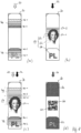
- FIG. 1 shows schematically a banknote 10 with a security element 12 according to the invention, the visual impression of which is shown under different lighting and viewing conditions
- Figures 2 and 3 is shown in more detail.
- Figure 2 specifically shows the appearance of the security element 12 when illuminated with only one type of light, either light 20 in the visible wavelength range (also referred to as daylight in this description) or UV light 22 Fig. 2(a) the appearance of the security element 12 in daylight 20 when viewed from an angle, Fig. 2(b) the appearance in daylight when viewed vertically and Fig. 2(c) the appearance of the security element 12 after UV excitation 22, which is essentially independent of the viewing direction.
- Figure 3 shows the appearance of the security element 12 when simultaneously illuminated with both types of light 20, 22, where Fig. 3(a) the appearance when viewed from an angle and Fig. 3(b) the appearance when viewed vertically.
- a security element 12 illustrates that contains two non-overlapping but adjacent motif areas 14, 16, which in the exemplary embodiment are defined by the upper and lower half of the arch of the in Fig. 1 shown arch motif are formed.
- the motif areas 14, 16 can also be arranged at a distance from one another, for example.
- the first motif area represents an optically variable daylight motif area 14, which shows two different appearances in visible light 20 (daylight) from different viewing directions.
- the motif area 14 appears with the color magenta (M) when viewed vertically, as in Fig. 2(b) shown, and when viewed from an angle with the color green (G), as in Fig. 2(a) shown.
- the second motif area represents a luminescence motif area 16, which is not visible in pure daylight lighting, and in the Figures 2(a) and 2(b) is therefore only shown with a dashed outline.
- UV excitation 22 shows the luminescence motif area 16 a multi-colored luminescence motif, in the exemplary embodiment Figures 2 and 3
- the luminescent motif luminesces with the luminescent colors magenta (M) and blue (B), respectively.
- the luminescent color magenta is a mixed color that is created by additive color mixing of luminescent red and luminescent blue.
- the daylight motif area 14 is hardly or not visible and in the Fig. 2(c) therefore only shown with a dashed outline.
- the luminescence motif of the color areas 16-1, 16-2 does not change when the security element 12 is tilted, but rather appears essentially the same when viewed vertically and when viewed at an angle or illuminated Fig. 2(c) illustrated color impression.
- a special feature of the optically variable daylight motif area 14 is its appearance when vertical Viewing adapted to the luminescence motif of the color areas 16-1, 16-2, the motif area 14 shows the same shade of magenta (M) as the partial area 16-1 of the luminescence motif. Reproducing such a color match between an optically variable area 14 and a luminescence area 16 represents a great challenge for a potential counterfeiter, especially if a mixed color matches, as here, or if several colors or even color gradients match, as shown in embodiments described further below.
- M magenta
- the color match can be checked by alternating illumination of the security element 12 with daylight 20 and UV light 22, but can in particular also be queried by simultaneous illumination with daylight and UV light, as in Fig. 3 illustrated.
- the in Fig. 3(a) shown oblique view of the daylight motif area 14 with the color green (G) and the luminescence area 16 in the first color area 16-1 with the color magenta (M) and in the second color area 16-2 with the color blue (B).
- the optically variable motif area 14 changes its appearance and then appears like the first color area 16-1 of the luminescence area with the color magenta (M).
- the color matching of areas 14 and 16-1 is immediately apparent to a viewer and can therefore be easily checked.
- the adjacent arrangement of the partial areas 14, 16 results in a visually easily recognizable and memorable completion of the partial motifs 14 and 16 to form an overall motif.
- FIG. 4(b) When viewed vertically, the optically variable daylight motif area 14 appears in visible light in a first color area 14-1 with the color magenta (M) and in a second color area 14-2 with the color blue (B).
- M color magenta
- B color blue
- the appearance of the area 14 changes due to the color shift effect from magenta to green and from blue to magenta, so that the first color area 14-1 has the color green (G) when viewed at an angle in daylight and the second color area 14-2 has the color tone (G).
- the color magenta (M) appears.
- the second motif area 16 is like that Figures 2 and 3 already described and shows upon UV excitation 22 a multicolored luminescence motif with a first color range 16-1 in the luminescence color magenta (M) and a second color range 16-2 in the luminescence color blue (B).
- the luminescence motif of the color areas 16-1, 16-2 does not change when the security element 12 is tilted and appears essentially the same when viewed vertically and obliquely or illuminated Fig. 4(c) illustrated color impression.
- the optically variable daylight motif area 14 is adapted to the luminescence motif in its two appearances, each with at least one color area. Given the appearance when viewed from an angle ( Figs. 4(a) and 4(c) ) namely, both the color range 14-2 of the daylight motif area 14 and the color area 16-1 of the luminescence motif area 16 appear the color magenta (M), so that there is an adaptation in one color area.
- M color magenta
- both the color range 14-1 of the daylight motif area 14 and the color range 16-1 of the luminescence motif area 16 appear with the color magenta (M)
- both the color range 14-2 of the daylight motif area 14 appear the color range 16-2 of the luminescence motif area 16 with the color blue (B).
- the color matches mentioned can be checked by alternating lighting with daylight 20 and UV light 22, can be checked with reference to Fig. 5 but can also be tested by simultaneous lighting with daylight and UV light.
- the in Fig. 5(a) In the oblique viewing direction shown, the color areas 14-2 and 16-1 are simultaneously in the color magenta (M).
- the color areas 14-1 and 16-1 appear simultaneously in the color magenta (M) and, on the other hand, the color areas 14-2 and 16-2 appear simultaneously in the color blue (B).
- FIGs 6 and 7 illustrate the use of the basic principle described in a more complex security element, namely a wide security strip 30 for application to a banknote 32, as in the daylight view of Fig. 6 illustrated.
- the security strip 30 is in Fig. 7 presented in more detail, where there Fig. 7(a) the appearance of the security strip 30 only in daylight 20, Fig. 7(b) the appearance of the security strip 30 only in UV light 22 and Fig. 7(c) the appearance of the security strip 30 when illuminated with both types of light 20, 22 shows.
- Figure 7(d) finally illustrates the appearance of an optional development of the security strip 30 in the IR light 24.
- the security strip 30 contains an optically variable daylight motif area 40 consisting of several partial areas 42, 44, the partial areas 42, 44 each containing a hologram 46 which, when viewed vertically, has a color gradient from a light blue color area 46-1 to a dark blue color area 46 -2 shows.
- the color gradient is illustrated in the figures as a four-stage progression, but in practice it can of course contain more stages or even be continuous.
- the security strip 30 further contains a luminescence motif area 50, which after UV excitation 22 shows a multicolored luminescence motif, which also consists of several partial areas 52, 54, 56.
- the partial areas represent a true color portrait 52 against the background of a blue sky 54 and a letter sequence 56.
- the sky background 54 shows a color gradient in the UV light 22 from a light blue color area 54-1 to a dark blue color area 54-2, wherein the hues of the color gradient and the color end points 54-1, 54-2 correspond to the hues of the color gradients and the color end points 46-1, 46-2 in the holograms 46 of the daylight motif area 40.
- the color match between the color gradient in the holograms 46 and the color gradient in the luminescent sky background 54 can now be checked when viewed vertically by alternating illumination with daylight 20 and UV light 22; it can be checked with reference to Fig. 7(c) However, it can also be checked by simultaneously illuminating the security strip 30 with daylight and UV light.
- the security features described in the visible and UV spectral range can be supplemented by further authenticity features.
- the partial areas 40, 50 can, for example, additionally contain an IR-absorbing substance 62, which is designed in a partial area in the form of a code, for example a QR code 60.
- a code for example a QR code 60.
- the change in the visual appearance of the security element when changing from daylight viewing to viewing under UV excitation can be combined with an optically variable luminescence motif.
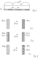
- an optically variable luminescence motif can be obtained, analogous to conventional lens tilt images, by arranging a regular arrangement of parallel cylindrical lenses 70 at a distance from a luminescence motif area 72, which is alternately divided into a plurality of parallel luminescent strips 74A, 74B.
- the strips 74A, 74B and the cylindrical lenses 70 are coordinated with one another in such a way that after UV excitation only the stripes 74A are visible from a first viewing direction and only the stripes 74B are visible from a second viewing direction and together they each produce a desired luminescence image.
- Figure 9 illustrates in (a) to (c) some possible visual appearances of such an optically variable luminescence motif when changing the viewing direction (arrow 90).
- Fig. 9(a) When exposed to UV excitation from a first viewing direction, the illustrated luminescence region 80 appears in a first color, for example red (R), while from a second viewing direction it appears in a second color, for example yellow (Y).
- R red
- Y yellow
- the luminescence area represents a two-color pattern of two parallel stripes 82, 84, the luminescence colors of which exchange one another when the viewing direction changes 90. From a first viewing direction, for example after UV excitation, the strips 82, 84 show the color sequence red-yellow (left part of the image), while from a second viewing direction they show the color sequence yellow-red (right part of the image).
- An additional motif 88 appears or disappears in the luminescence area 86 when tilting 90.
- the luminescence area 86 appears uniformly red (R), while from a second viewing direction additional coat of arms motifs 88 appear in yellow (Y) against the red background are visible.
- Such optically variable luminescence effects cannot only be achieved with lens arrangements Fig. 8 , but also, for example, with prism arrangements or with blind grids, in which case the grid elements can be formed in particular from opaque or transparent UV blockers.
- luminescent microimages of the same or different colors are used in the context of the present application. In daylight, the microimages can either be invisible, for example transparent or have the same body color as the background, or they can be visible and have the same or different colors.
- Figure 10 shows, by way of example, different motif images 100 of such moiré enlargement arrangements, as can be provided, for example, in a security thread as part of a security element described above.
- the regularly arranged microimages are each designed in the form of a star for illustration, but in practice they can have any other shape.
- the Figures 10(a) to 10(d) The appearance of the motif images in daylight 20 is shown in each case, and the appearance in UV light 22 is shown in the right half of the image.
- the microimages 102 are initially designed so that they all have the same color tone 104-F in daylight 20, while the microimages 102 glow in different luminescence colors 106-A, 106-B, 106-C, 106-D in UV light 22.
- the moiré effect results in a dynamic movement effect when the security element is tilted when viewed in both daylight 20 and UV light 22, with the moving, moiré-enlarged stars appearing monochromatic in daylight 20, but with different colors in UV light 22 Luminescent colors 106-A to 106-D light up.
- the microimages 102 are transparent in visible light 20 and their position is therefore only shown in dashed lines in the figure, while in UV light 22 they glow in different luminescence colors 106-A, 106-B, 106-C, 106-D.
- the motif image 100 thus produces no recognizable image and no movement effect, while in UV light 22, when the security element is tilted, a dynamic movement effect with moving, moiré-enlarged stars shining in the luminescent colors 106-A to 106-D is visible becomes.
- the microimages 102 are designed so that they all have the same color tone 104-F in daylight 20, and also all shine in the same color tone 106-G in UV light 22.
- the common daylight color 104-F and the common luminescence color 106-G can be the same or different.
- the moiré effect results in a monochrome dynamic movement effect in both daylight 20 and UV light 22 when the security element is tilted.
- the exemplary embodiment of the Fig. 10(d) finally shows a design in which the microimages 102 are designed so that they all have the same color tone 106-G in UV light 22, while in daylight 20 they have different colors 104-A, 104-B, 104-C, 104 -D appear.
- the moiré effect results in a dynamic movement effect in both daylight 20 and UV light 22 when the security element is tilted, with the moving, moiré-enlarged stars shining in one color in UV light 22, but with different colors 104 in daylight 20 -A to 104-D appear.
Landscapes
- Credit Cards Or The Like (AREA)
- Inspection Of Paper Currency And Valuable Securities (AREA)
Description
Die Erfindung betrifft ein Sicherheitselement mit einem Lumineszenz-Motivbereich zur Absicherung von Sicherheitspapieren, Wertdokumenten und anderen Datenträgern. Die Erfindung betrifft auch ein Verfahren zur Herstellung eines solchen Sicherheitselements sowie einen mit einem solchen Sicherheitselement ausgestatteten Datenträger.The invention relates to a security element with a luminescent motif area for securing security papers, valuable documents and other data carriers. The invention also relates to a method for producing such a security element and to a data carrier equipped with such a security element.
Datenträger, wie Wert- oder Ausweisdokumente, aber auch andere Wertgegenstände, wie etwa Markenartikel, werden zur Absicherung oft mit Sicherheitselementen versehen, die eine Überprüfung der Echtheit des Datenträgers gestatten und die zugleich als Schutz vor unerlaubter Reproduktion dienen.Data carriers, such as valuables or identification documents, but also other valuables, such as branded items, are often provided with security elements for security purposes, which allow the authenticity of the data carrier to be checked and which also serve as protection against unauthorized reproduction.
In diesem Zusammenhang ist es seit längerem bekannt, Lumineszenzstoffe zur Absicherung von Wert- oder Ausweisdokumenten einzusetzen. Das Vorliegen der Lumineszenzstoffe kann dann beispielsweise mit Hilfe einer UV-Lampe geprüft werden. Beispielsweise können in ein Sicherheitspapier fluoreszierende Melierfasern eingebracht sein, welche üblicherweise aus kurzen, mit einer fluoreszierenden Beschichtung versehenen Fasern bestehen. Bei normaler Beleuchtung sind die Melierfasern unsichtbar, unter UV-Beleuchtung treten sie jedoch durch ihre helle Fluoreszenz, beispielsweise in Rot, Grün oder Blau, trotz ihrer geringen Größe deutlich in Erscheinung. Insbesondere im Pass-Bereich ist auch der Druck von Echtfarben-Lumineszenzbildern bekannt. Die Umsetzung erfolgt dabei in der Regel im Ink-Jet-Druck mit speziellen Farben, welche bei normaler Beleuchtung nicht sichtbar sind und nach Anregung mittels UV-Licht einen vergleichbaren Farbeindruck wie ein klassisches Bild, beispielsweise ein Portrait des Passinhabers, zeigen.In this context, it has long been known to use luminescent substances to secure valuables or identification documents. The presence of the luminescent substances can then be checked, for example, using a UV lamp. For example, fluorescent mottled fibers can be incorporated into a security paper, which usually consist of short fibers provided with a fluorescent coating. The mottled fibers are invisible under normal lighting, but under UV lighting they become clearly visible despite their small size due to their bright fluorescence, for example in red, green or blue. The printing of true color luminescence images is also known, particularly in the passport area. The implementation is usually carried out using ink-jet printing with special colors that are not visible under normal lighting and, when stimulated using UV light, show a color impression comparable to that of a classic image, for example a portrait of the passport holder.
Allerdings sind inzwischen vor allem durch den Online-Handel Ink-Jet-Fluoreszenzfarben relativ leicht verfügbar, die es einem Fälscher ermöglichen, Eindrucksfälschungen herzustellen. Auch bieten Druckfarbenhersteller teilweise Fluoreszenzfarben an, die für technische Spielereien oder den Markenschutz bestimmt sind.However, ink-jet fluorescent inks are now relatively easily available, especially through online trading, which enables a counterfeiter to produce fake impressions. Printing ink manufacturers also sometimes offer fluorescent inks that are intended for technical gadgets or brand protection.
Diese Aufgabe wird durch die Merkmale der unabhängigen Ansprüche gelöst. Weiterbildungen der Erfindung sind Gegenstand der abhängigen Ansprüche.This task is solved by the features of the independent claims. Further developments of the invention are the subject of the dependent claims.
Gemäß der Erfindung umfasst das Sicherheitselement einen optisch variablen Tageslicht-Motivbereich, der im sichtbaren Licht aus unterschiedlichen Betrachtungsrichtungen zumindest zwei unterschiedliche Erscheinungsbilder zeigt, und einen Lumineszenz-Motivbereich, der nach UV-Anregung zumindest ein mehrfarbiges Lumineszenzmotiv zeigt. Der optisch variable Tageslicht-Motivbereich ist in zumindest einem seiner Erscheinungsbilder an das zumindest eine mehrfarbige Lumineszenzmotiv angepasst, nämlich
- mindestens einen Bereich mit demselben Farbverlauf aufweist, wie ein Bereich des mehrfarbigen Lumineszenzmotivs, wobei der optisch variable Tageslicht-Motivbereich in zumindest einem seiner Erscheinungsbilder und das zumindest eine mehrfarbige Lumineszenzmotiv mindestens zwei Bereiche mit demselben Farbton aufweisen, wobei zwischen den zwei genannten Bereichen mit demselben Farbton jeweils derselbe Farbverlauf vom Farbton des ersten Bereichs zum Farbton des zweiten Bereichs vorliegt; oder
- mindestens einen Bereich mit demselben Farbton aufweist, wie ein Bereich des mehrfarbigen Lumineszenzmotivs, wobei
- der Lumineszenz-Motivbereich ein Echtfarb-Lumineszenzbereich ist, der Mischfarben aus mindestens zwei Lumineszenz-Grundfarben enthält, oder
- der optisch variable Tageslicht-Motivbereich und der Lumineszenz-Motivbereich aneinander angrenzend oder beabstandet auf dem Sicherheitselement angeordnet sind, oder
- der optisch variable Tageslicht-Motivbereich und der Lumineszenz-Motivbereich einander zu einem Gesamtmotiv ergänzende Motivteile bilden.
- has at least one area with the same color gradient as an area of the multicolored luminescence motif, the optically variable daylight motif area having at least one of its appearances and the at least one multicolored luminescence motif having at least two areas with the same color tone, with the same color tone between the two mentioned areas In each case the same color gradient is present from the color tone of the first area to the color tone of the second area; or
- has at least one area with the same color tone as an area of the multicolored luminescent motif, wherein
- the luminescence motif area is a true color luminescence area that contains mixed colors of at least two luminescence primary colors, or
- the optically variable daylight motif area and the luminescence motif area are arranged adjacent or spaced apart on the security element, or
- the optically variable daylight motif area and the luminescence motif area form motif parts that complement each other to form an overall motif.
Die Begriffe sichtbares Licht und Tageslicht werden in dieser Anmeldung synonym für Licht aus dem sichtbaren Wellenlängenbereich (etwa 380 nm bis 780 nm) verwendet. UV-Licht oder UV-Anregung bezeichnet Licht aus dem ultravioletten Wellenlängenbereich von etwa 100 nm bis 380 nm.The terms visible light and daylight are used in this application synonymously for light from the visible wavelength range (approximately 380 nm to 780 nm). UV light or UV excitation refers to light from the ultraviolet wavelength range from approximately 100 nm to 380 nm.
Durch die genannte Anpassung wird eine Wechselwirkung zwischen dem optisch variablen Tageslicht-Motivbereich und dem mehrfarbigen Lumineszenzmotiv geschaffen, die zwei in verschiedenen Beleuchtungssituationen sichtbare Sicherheitsmerkmale miteinander verknüpft und daher die Absicherungswirkung des Sicherheitselements erhöht.The adaptation mentioned creates an interaction between the optically variable daylight motif area and the multicolored luminescence motif, which links two security features that are visible in different lighting situations and therefore increases the security effect of the security element.
Die genannte Anpassung kann dadurch verwirklicht sein, dass der optisch variable Tageslicht-Motivbereich mit einer Farbe in zumindest einem seiner Erscheinungsbilder an das zumindest eine mehrfarbige Lumineszenzmotiv angepasst ist. Eine Anpassung in der Farbe bedeutet dabei, dass der Farbton zumindest eines Teilbereichs des Tageslicht-Motivbereichs mit dem LumineszenzFarbton eines Teilbereichs des zumindest einen mehrfarbigen Lumineszenzmotivs übereinstimmt.The adaptation mentioned can be realized by adapting the optically variable daylight motif area with a color in at least one of its appearances to the at least one multicolored luminescence motif. An adjustment in color means that the color tone of at least a portion of the daylight motif area matches the luminescence color tone of a portion of the at least one multicolored luminescence motif.
Es ist dabei vorgesehen, dass der optisch variable Tageslicht-Motivbereich in zumindest einem seiner Erscheinungsbilder und das zumindest eine mehrfarbige Lumineszenzmotiv mindestens zwei Bereiche mit demselben Farbton aufweisen. In einem Aspekt liegt zwischen den zwei genannten Bereichen mit demselben Farbton sogar jeweils derselbe Farbverlauf vom Farbton des ersten Bereichs zum Farbton des zweiten Bereichs vor.It is provided that the optically variable daylight motif area has at least two areas with the same color tone in at least one of its appearances and the at least one multicolored luminescence motif. In one aspect, there is even the same color gradient between the two mentioned areas with the same color tone from the color tone of the first area to the color tone of the second area.
Die Nachstellung einer Farbübereinstimmung zwischen einem optisch variablen Bereich und einem Lumineszenz-Motivbereich stellt eine große Herausforderung für einen potentiellen Fälscher dar, insbesondere wenn mehrere Farben, eine Mischfarbe aus mehreren Grundfarben oder sogar ein Farbverlauf übereinstimmen müssen.Recreating a color match between an optically variable area and a luminescent motif area represents a major challenge for a potential counterfeiter, especially when multiple colors, a mixed color of multiple primary colors, or even a color gradient must match.
Der Lumineszenz-Motivbereich ist in einem weiteren Aspekt ein Echtfarb-Lumineszenzbereich, der Mischfarben aus mindestens zwei, vorzugsweise drei Lumineszenz-Grundfarben enthält. Insbesondere enthält der Echtfarb-Lumineszenzbereich Mischfarben aus Lumineszenzgrün, Lumineszenzrot und Lumineszenzblau.In a further aspect, the luminescence motif area is a true-color luminescence area that contains mixed colors of at least two, preferably three, luminescence primary colors. In particular, the true color luminescence area contains mixed colors of luminescence green, luminescence red and luminescence blue.
Der optisch variable Tageslicht-Motivbereich und der Lumineszenz-Motivbereich sind in einem anderen Aspekt aneinander angrenzend oder beabstandet voneinander auf dem Sicherheitselement angeordnet. Insbesondere können die aneinander angepassten Teilbereiche des Tageslicht-Motivbereichs und des Lumineszenz-Motivbereichs aneinander angrenzend angeordnet sein, so dass die Anpassung, beispielsweise im Farbton, besonders auffällig ist und leicht geprüft werden kann.In another aspect, the optically variable daylight motif area and the luminescence motif area are arranged adjacent to one another or spaced apart from one another on the security element. In particular, the mutually adapted partial areas of the daylight motif area and the luminescence motif area can be arranged adjacent to one another, so that the adjustment, for example in color tone, is particularly noticeable and can be easily checked.
In einer anderen, ebenfalls vorteilhaften Ausgestaltung sind der optisch variable Tageslicht-Motivbereich und der Lumineszenz-Motivbereich einander überlappend auf dem Sicherheitselement angeordnet, wobei der Tageslicht-Motivbereich und der Lumineszenz-Motivbereich im Überlappungsbereich in ihrer Farbe aneinander angepasst sind.In another, also advantageous embodiment, the optically variable daylight motif area and the luminescence motif area are arranged to overlap one another on the security element, with the daylight motif area and the luminescence motif area being matched in color to one another in the overlap area.
Der optisch variable Tageslicht-Motivbereich und der Lumineszenz-Motivbereich bilden in einem noch anderen Aspekt einander zu einem Gesamtmotiv ergänzende Motivteile. Insbesondere bei gleichzeitiger Beleuchtung mit Tageslicht und UV-Licht ist die Ergänzung der einzelnen Motivteile zu einem Gesamtmotiv sehr auffällig. Die bereits genannte Anpassung stellt zusätzlich eine Wechselwirkung zwischen den beiden Motivteilen bereit, die neben der Ergänzung zu einem Gesamtmotiv als Echtheitskennzeichen dient.In yet another aspect, the optically variable daylight motif area and the luminescence motif area form motif parts that complement one another to form an overall motif. Especially when illuminated with daylight and UV light at the same time, the addition of the individual parts of the motif to an overall motif is very noticeable. The adaptation already mentioned also provides an interaction between the two parts of the motif, which, in addition to complementing an overall motif, serves as an indicator of authenticity.
Der optisch variable Tageslicht-Motivbereich enthält bevorzugt ein oder mehrere Elemente ausgewählt aus der Gruppe bestehend aus Hologrammen, hologrammähnlichen Beugungsstrukturen, Beugungsmustern, Strukturen mit Farbkippeffekt, Kinoformen, Strukturen mit einem Mikrolinseneffekt, und mikrooptischen Darstellungsanordnungen, insbesondere Moire-Vergrößerungsanordnungen und Linsenrasterbildern.The optically variable daylight motif area preferably contains one or more elements selected from the group consisting of holograms, hologram-like diffraction structures, diffraction patterns, structures with a color-shifting effect, cinema shapes, structures with a microlens effect, and micro-optical display arrangements, in particular moire magnification arrangements and lenticular images.
Der Lumineszenz-Motivbereich kann optisch nicht-variabel ausgebildet sein, in einer vorteilhaften Weiterbildung der Erfindung ist der Lumineszenz-Motivbereich allerdings ebenfalls optisch variabel ausgebildet und zeigt daher nach UV-Anregung aus unterschiedlichen Anregungsrichtungen zumindest zwei unterschiedliche Erscheinungsbilder, oder zeigt nach UV-Anregung zumindest zwei unterschiedliche Erscheinungsbilder aus unterschiedlichen Betrachtungsrichtungen. Weiter kann der Lumineszenz-Motivbereich auch bei Anregung mit unterschiedlichen Anregungswellenlängen (beispielsweise 254 nm und 365 nm) unterschiedliche Erscheinungsbilder zeigen.The luminescence motif area can be designed to be optically non-variable, but in an advantageous development of the invention the luminescence motif area is also designed to be optically variable and therefore shows at least two different appearances after UV excitation from different excitation directions, or at least shows after UV excitation two different appearances from different viewing directions. Furthermore, the luminescence motif region can also show different appearances when excited with different excitation wavelengths (for example 254 nm and 365 nm).
Zeigt der Lumineszenz-Motivbereich unterschiedliche Erscheinungsbilder, so ist erfindungsgemäß der optisch variable Tageslicht-Motivbereich in zumindest einem seiner Erscheinungsbilder an wenigstens eines der Erscheinungsbilder des Lumineszenz-Motivbereichs angepasst. Der Tageslicht-Motivbereich kann natürlich vorteilhaft auch an alle Erscheinungsbilder des Lumineszenz-Motivbereichs angepasst sein.If the luminescence motif area shows different appearances, then according to the invention the optically variable daylight motif area is adapted in at least one of its appearances to at least one of the appearances of the luminescence motif area. The daylight motif area can of course also be advantageously adapted to all appearances of the luminescence motif area.
Ein optisch variabel ausgebildeter Lumineszenz-Motivbereich ist mit Vorteil Teil einer mikrooptischen Darstellungsanordnung, insbesondere einer Moire-Vergrößerungsanordnung oder eines Linsenrasterbilds.An optically variable luminescence motif area is advantageously part of a micro-optical display arrangement, in particular a Moire magnification arrangement or a lenticular image.
In einer Weiterbildung der Erfindung ist vorgesehen, dass der optisch variable Tageslicht-Motivbereich und/oder der Lumineszenz-Motivbereich eine IR-absorbierende Substanz enthalten, vorzugsweise im Form von Mustern, Zeichen oder einer Codierung, wie einem Barcode oder QR-Code.In a further development of the invention it is provided that the optically variable daylight motif area and/or the luminescence motif area contain an IR-absorbing substance, preferably in the form of patterns, characters or a coding, such as a barcode or QR code.
Das Sicherheitselement ist mit Vorteil ein Sicherheitsfaden, insbesondere ein Fenstersicherheitsfaden oder ein Pendelsicherheitsfaden, ein Aufreißfaden, ein Sicherheitsband, ein Sicherheitsstreifen, ein Patch oder ein Etikett zum Aufbringen auf ein Sicherheitspapier, Wertdokument oder dergleichen.The security element is advantageously a security thread, in particular a window security thread or a pendulum security thread, a tear thread, a security tape, a security strip, a patch or a label for application to a security paper, document of value or the like.
Weiter kann das Sicherheitselement mit Vorteil von gegenüberliegenden Seiten unterschiedliche Erscheinungsbilder im Tageslicht und im UV-Licht zeigen. Dazu sind insbesondere unterschiedliche Lumineszenz-Motivbereiche auf den gegenüberliegenden Seiten des Sicherheitselements vorgesehen, die zumindest teilweise durch einen UV-Blocker voneinander getrennt sind.Furthermore, the security element can advantageously show different appearances in daylight and in UV light from opposite sides. For this purpose, in particular, different luminescence motif areas are provided on the opposite sides of the security element, which are at least partially separated from one another by a UV blocker.
Die Erfindung enthält auch einen Datenträger mit einem Sicherheitselement der beschriebenen Art. Das Sicherheitselement kann dabei insbesondere in einem Fensterbereich des Datenträgers angeordnet sein, beispielsweise über einer Öffnung oder einem transparenten oder transluzenten Teilbereich des Datenträgers. In diesem Fall kann das Sicherheitselement mit Vorteil von gegenüberliegenden Seiten unterschiedliche Erscheinungsbilder zeigen.The invention also contains a data carrier with a security element of the type described. The security element can in particular be arranged in a window area of the data carrier, for example above an opening or a transparent or translucent partial area of the data carrier. In this case, the security element can advantageously show different appearances from opposite sides.
Bei dem Datenträger kann es sich insbesondere um ein Wertdokument, wie eine Banknote, insbesondere eine Papierbanknote, eine Polymerbanknote oder eine Folienverbundbanknote, um eine Aktie, eine Anleihe, eine Urkunde, einen Gutschein, einen Scheck, eine hochwertige Eintrittskarte, aber auch um eine Ausweiskarte, wie etwa eine Kreditkarte, eine Bankkarte, eine Barzahlungskarte, eine Berechtigungskarte, einen Personalausweis oder eine Passpersonalisierungsseite handeln.The data carrier can in particular be a document of value, such as a banknote, in particular a paper banknote, a polymer banknote or a film composite banknote, a share, a bond, a certificate, a voucher, a check, a high-quality admission ticket, but also an ID card , such as a credit card, a debit card, a cash card, an authorization card, an ID card or a passport personalization page.
Die Erfindung enthält schließlich auch ein Verfahren nach Anspruch 16 bis 19.Finally, the invention also contains a method according to
Weitere Ausführungsbeispiele sowie Vorteile der Erfindung werden nachfolgend anhand der Figuren erläutert, bei deren Darstellung auf eine maßstabs- und proportionsgetreue Wiedergabe verzichtet wurde, um die Anschaulichkeit zu erhöhen.Further exemplary embodiments and advantages of the invention are explained below with reference to the figures, which are not reproduced to scale and proportions in order to increase clarity.
Es zeigen:
- Fig. 1
- schematisch eine Banknote mit einem erfindungsgemäßen Sicherheitselement,
- Fig. 2
- das Erscheinungsbild des Sicherheitselements der
Fig. 1 bei Beleuchtung mit nur einer Lichtsorte, in (a) im Tageslicht bei schräger Betrachtung, in (b) im Tageslicht bei senkrechter Betrachtung und in (c) bei UV-Anregung bei senkrechter oder schräger Betrachtung, - Fig. 3
- das Erscheinungsbild des Sicherheitselements der
Fig. 1 bei gleichzeitiger Beleuchtung mit Tageslicht und UV-Licht, in (a) bei schräger Betrachtung und in (b) bei senkrechter Betrachtung, - Fig. 4
- das Erscheinungsbild eines Sicherheitselements nach einem weiteren Ausführungsbeispiel der Erfindung, in (a) im Tageslicht bei schräger Betrachtung, in (b) im Tageslicht bei senkrechter Betrachtung und in (c) bei UV-Anregung bei senkrechter oder schräger Betrachtung,
- Fig. 5
- das Erscheinungsbild des Sicherheitselements der
Fig. 4 bei gleichzeitiger Beleuchtung mit Tageslicht und UV-Licht, in (a) bei schräger Betrachtung und in (b) bei senkrechter Betrachtung, - Fig. 6
- eine Banknote mit einem Sicherheitsstreifen nach einem weiteren Ausführungsbeispiel der Erfindung in Tageslichtansicht,
- Fig. 7
- das Erscheinungsbild des Sicherheitsstreifens der
Fig. 6 bei verschiedenen Beleuchtungsbedingungen, in (a) nur im Tageslicht, in (b) nur im UV-Licht, in (c) bei gleichzeitiger Beleuchtung mit Tageslicht und UV-Licht, und in (d) im Infrarot-Licht, - Fig. 8
- eine Anordnung zur Erzeugung eines optisch variablen Lumineszenzmotivs,
- Fig. 9
- in (a) bis (c) beispielhaft visuelle Erscheinungsbilder eines optisch variablen Lumineszenzmotivs beim Wechsel der Betrachtungsrichtung, und
- Fig. 10
- in (a) bis (d) unterschiedliche lumineszierende Motivbilder von Moiré-Vergrößerungsanordnungen, wobei in der linken Bildhälfte jeweils das Erscheinungsbild im Tageslicht und in der rechten Bildhälfte das Erscheinungsbild im UV-Licht gezeigt ist.
- Fig. 1
- schematically a banknote with a security element according to the invention,
- Fig. 2
- the appearance of the security element
Fig. 1 when illuminated with only one type of light, in (a) in daylight when viewed at an angle, in (b) in daylight when viewed vertically and in (c) with UV excitation when viewed vertically or obliquely, - Fig. 3
- the appearance of the security element
Fig. 1 with simultaneous illumination with daylight and UV light, in (a) when viewed at an angle and in (b) when viewed vertically, - Fig. 4
- the appearance of a security element according to a further exemplary embodiment of the invention, in (a) in daylight when viewed at an angle, in (b) in daylight when viewed vertically and in (c) under UV excitation when viewed vertically or at an angle,
- Fig. 5
- the appearance of the security element
Fig. 4 with simultaneous illumination with daylight and UV light, in (a) when viewed at an angle and in (b) when viewed vertically, - Fig. 6
- a banknote with a security strip according to a further exemplary embodiment of the invention in daylight view,
- Fig. 7
- the appearance of the security strip
Fig. 6 under different lighting conditions, in (a) only in daylight, in (b) only in UV light, in (c) with simultaneous illumination with daylight and UV light, and in (d) in infrared light, - Fig. 8
- an arrangement for generating an optically variable luminescence motif,
- Fig. 9
- in (a) to (c) exemplary visual appearances of an optically variable luminescence motif when changing the viewing direction, and
- Fig. 10
- in (a) to (d) different luminescent motif images from moiré enlargement arrangements, the appearance in daylight being shown in the left half of the image and the appearance in UV light being shown in the right half of the image.
Die Erfindung wird nun am Beispiel der Absicherung von Banknoten erläutert.
Dabei zeigt
Zur Erläuterung des Grundprinzips der Erfindung ist in den
Der erste Motivbereich stellt einen optisch variablen Tageslicht-Motivbereich 14 dar, der im sichtbaren Licht 20 (Tageslicht) aus unterschiedlichen Betrachtungsrichtungen zwei unterschiedliche Erscheinungsbilder zeigt. Im Ausführungsbeispiel erscheint der Motivbereich 14 bei senkrechter Betrachtung mit dem Farbton Magenta (M), wie in
Der zweite Motivbereich stellt einen Lumineszenz-Motivbereich 16 dar, der bei reiner Tageslichtbeleuchtung nicht erkennbar ist, und in den
Bei reiner UV-Beleuchtung ist der Tagelicht-Motivbereich 14 kaum oder nicht erkennbar und in der
Als Besonderheit ist der optisch variable Tageslicht-Motivbereich 14 in seinem Erscheinungsbild bei senkrechter Betrachtung an das Lumineszenzmotiv der Farbbereiche 16-1, 16-2 angepasst, zeigt nämlich im Motivbereich 14 denselben Farbton Magenta (M) wie der Teilbereich 16-1 des Lumineszenzmotivs. Die Nachstellung einer solchen Farbübereinstimmung zwischen einem optisch variablen Bereich 14 und einem Lumineszenzbereich 16 stellt eine große Herausforderung für einen potentiellen Fälscher dar, insbesondere wenn wie hier eine Mischfarbe übereinstimmt, oder wenn mehrere Farben oder sogar Farbverläufe übereinstimmen, wie in weiter unten beschriebenen Ausgestaltungen gezeigt.A special feature of the optically variable
Die Farbübereinstimmung kann durch abwechselnde Beleuchtung des Sicherheitselements 12 mit Tageslicht 20 und UV-Licht 22 geprüft werden, kann aber insbesondere auch durch eine gleichzeitige Beleuchtung mit Tageslicht und UV-Licht abgefragt werden, wie in
Bei gleichzeitiger Beleuchtung mit Tageslicht 20 und UV-Licht 22 erscheint bei der in
Die
Der zweite Motivbereich 16 ist wie bei den
Als Besonderheit ist der optisch variable Tageslicht-Motivbereich 14 in seinen beiden Erscheinungsbildern mit jeweils zumindest einem Farbbereich an das Lumineszenzmotiv angepasst. Bei dem Erscheinungsbild bei schräger Betrachtung (
Bei dem Erscheinungsbild bei senkrechter Betrachtung gibt es sogar zwei aneinander angepasste Bereiche in den Motivbereichen 14,16, wie in
Die genannten Farbübereinstimmungen können durch abwechselnde Beleuchtung mit Tageslicht 20 und UV-Licht 22 geprüft werden, können mit Bezug auf
Es ist natürlich auch möglich, die Farbbereiche der Bereiche 14, 16 so aufeinander abzustimmen, dass nur bei einer Betrachtungsrichtung, beispielsweise der senkrechten Betrachtungsrichtung der
Die
Mit Bezug zunächst auf
Mit Bezug auf
Die Farbübereinstimmung zwischen dem Farbverlauf in den Hologrammen 46 und dem Farbverlauf in dem lumineszierenden Himmelshintergrund 54 kann nun bei senkrechter Betrachtung durch abwechselnde Beleuchtung mit Tageslicht 20 und UV-Licht 22 geprüft werden, sie kann mit Bezug auf
Bei gleichzeitiger Beleuchtung mit Tageslicht 20 und UV-Licht 22 sind nämlich bei der in
Die beschriebenen Sicherheitsmerkmale im sichtbaren und UV-Spektralbereich können durch weitere Echtheitsmerkmale ergänzt werden. Mit Bezug auf
Nach einer anderen Weiterbildung kann die Änderung des visuellen Erscheinungsbilds des Sicherheitselements beim Wechsel von Tageslicht-Betrachtung zu Betrachtung bei UV-Anregung mit einem optisch variablen Lumineszenzmotiv kombiniert sein.According to another development, the change in the visual appearance of the security element when changing from daylight viewing to viewing under UV excitation can be combined with an optically variable luminescence motif.
Mit Bezug auf
Bei dem Ausführungsbeispiel der
Beim Ausführungsbeispiel der
Solche optisch variablen Lumineszenzeffekte lassen sich nicht nur mit Linsenanordnungen nach
Eine weitere Möglichkeit, optisch variable Lumineszenzmotive zu erzeugen, besteht im Einsatz von Moire-Vergrößerungsanordnungen, wie sie als solche grundsätzlich beispielsweise in den Druckschriften
Im Ausführungsbeispiel der
Beim Ausführungsbeispiel der
Beim Ausführungsbeispiel der
Das Ausführungsbeispiel der
- 1010
- BanknoteBanknote
- 1212
- SicherheitselementSecurity element
- 1414
- optisch variabler Tageslicht-Motivbereichoptically variable daylight motif area
- 14-1,14-214-1,14-2
- FarbbereicheColor ranges
- 1616
- Lumineszenz-MotivbereichLuminescent motif area
- 16-1,16-216-1,16-2
- FarbbereicheColor ranges
- 2020
- Tageslichtdaylight
- 2222
- UV-LichtUV light
- 2424
- IR-LichtIR light
- 3030
- SicherheitsstreifenSecurity strips
- 3232
- BanknoteBanknote
- 4040
- optisch variabler Tageslicht-Motivbereichoptically variable daylight motif area
- 42,4442.44
- TeilbereicheSub-areas
- 4646
- Hologrammhologram
- 46-1,46-246-1,46-2
- FarbbereicheColor ranges
- 5050
- Lumineszenz-MotivbereichLuminescent motif area
- 5252
- Teilbereich, Echtfarb-PortraitPartial, true color portrait
- 5454
- Teilbereich, HimmelshintergrundPartial area, sky background
- 5656
- Teilbereich, BuchstabenfolgePartial area, sequence of letters
- 6060
- QR-CodeQR code
- 6262
- IR-absorbierende SubstanzIR-absorbing substance
- 7070
- ZylinderlinsenCylindrical lenses
- 7272
- Lumineszenz-MotivbereichLuminescent motif area
- 74A, 74B74A, 74B
- lumineszierende Streifenluminescent strips
- 8080
- LumineszenzbereichLuminescence area
- 82, 8482, 84
- lumineszierende parallele Streifenluminescent parallel stripes
- 8686
- LumineszenzbereichLuminescence area
- 8888
- zusätzliches Motivadditional motif
- 9090
- Wechsel der BetrachtungsrichtungChange of viewing direction
- 100100
- MotivbildMotif image
- 102102
- MikrobilderMicro images
- 104-A, 104-B, 104-C, 104-D104-A, 104-B, 104-C, 104-D
- TageslichtfarbenDaylight colors
- 104-F104-F
- TageslichtfarbtonDaylight hue
- 106-A, 106-B, 106-C, 106-D106-A, 106-B, 106-C, 106-D
- LumineszenzfarbenLuminescent colors
- 106-G106-G
- LumineszenzfarbtonLuminescent hue
Claims (19)
- Security element (12) for securing security papers, value documents and other data carriers (10), with- an optically variable daylight motif region (14) that shows at least two different appearances (14G, 14M) in visible light (20) from different viewing directions, and- a luminescence motif region (16) that shows at least one luminescence motif (16-1, 16-2) after UV excitation, wherein the luminescence motif is a multicolored luminescence motif, andwherein the optically variable daylight motif region is adapted in at least one of its appearances to the at least one multicolored luminescence motif, namely has at least one region with the same color gradation as a region of the multicolored luminescence motif, andwherein the optically variable daylight motif region in at least one of its appearances and the at least one multicolored luminescence motif have at least two regions with the same color tone, wherein between the two stated regions with the same color tone the same color gradation from the color tone of the first region to the color tone of the second region is present in each case.
- Security element (12) for securing security papers, value documents and other data carriers (10), with- an optically variable daylight motif region (14) that shows at least two different appearances (14G, 14M) in visible light (20) from different viewing directions, and- a luminescence motif region (16) that shows at least one luminescence motif (16-1, 16-2) after UV excitation, wherein the luminescence motif is a multicolored luminescence motif, andwherein the optically variable daylight motif region is adapted in at least one of its appearances to the at least one multicolored luminescence motif, namely has at least one region with the same color tone as a region of the multicolored luminescence motif, andwherein the luminescence motif region is a true-color luminescence region which contains mixed colors of at least two luminescence basic colors.
- Security element (12) for securing security papers, value documents and other data carriers (10), with- an optically variable daylight motif region (14) that shows at least two different appearances (14G, 14M) in visible light (20) from different viewing directions, and- a luminescence motif region (16) that shows at least one luminescence motif (16-1, 16-2) after UV excitation, wherein the luminescence motif is a multicolored luminescence motif,wherein the optically variable daylight motif region is adapted in at least one of its appearances to the at least one multicolored luminescence motif, namely has at least one region with the same color tone as a region of the multicolored luminescence motif, andwherein the optically variable daylight motif region and the luminescence motif region are arranged adjacent to one another or spaced apart on the security element.
- Security element (12) for securing security papers, value documents and other data carriers (10), with- an optically variable daylight motif region (14) that shows at least two different appearances (14G, 14M) in visible light (20) from different viewing directions, and- a luminescence motif region (16) that shows at least one luminescence motif (16-1, 16-2) after UV excitation, wherein the luminescence motif is a multicolored luminescence motif,wherein the optically variable daylight motif region is adapted in at least one of its appearances to the at least one multicolored luminescence motif, namely has at least one region with the same color tone as a region of the multicolored luminescence motif, andwherein the optically variable daylight motif region and the luminescence motif region form motif parts which complement one another to form an overall motif.
- Security element according to at least one of Claims 2 to 4, characterized in that the optically variable daylight motif region in at least one of its appearances and the at least one multicolored luminescence motif have at least two regions with the same color tone, that between the two stated regions with the same color tone the same color gradation from the color tone of the first region to the color tone of the second region is present in each case.
- Security element according to at least one of Claims 1 and 3 to 5, characterized in that the luminescence motif region is a true-color luminescence region which contains mixed colors of at least two, preferably three, luminescence basic colors, in particular mixed colors of luminescence green, luminescence red and luminescence blue.
- Security element according to at least one of Claims 1, 2 and 4 to 6, characterized in that the optically variable daylight motif region and the luminescence motif region are arranged adjacent to one another or spaced apart on the security element.
- Security element according to at least one of Claims 1, 2 and 4 to 6, characterized in that the optically variable daylight motif region and the luminescence motif region are arranged to overlap one another on the security element and the daylight motif region and the luminescence motif region in the overlap region are adapted to one another in terms of their color.
- Security element according to at least one of Claims 1 to 3 and 5 to 8, characterized in that the optically variable daylight motif region and the luminescence motif region form motif parts which complement one another to form an overall motif.
- Security element according to at least one of Claims 1 to 9, characterized in that the optically variable daylight motif region contains one or several elements selected from the group consisting of holograms, hologram-like diffraction structures, diffraction patterns, structures with a color shift effect, kinoforms, structures with a microlens effect, microoptical display arrangements, in particular moiré magnification arrangements and lens-grid images.
- Security element according to at least one of Claims 1 to 10, characterized in that the luminescence motif region is configured to be optically variable and shows at least two different appearances after UV excitation from different excitation directions, or shows at least two different appearances from different viewing directions after UV excitation.
- Security element according to Claim 11, characterized in that the luminescence motif region configured to be optically variable is part of a micro-optical display arrangement, in particular of a moiré magnification arrangement or of a lens-grid image.
- Security element according to at least one of Claims 1 to 12, characterized in that the optically variable daylight motif region and/or the luminescence motif region contain an IR-absorbing substance, preferably in the form of patterns, characters or a coding, such as a bar code or QR code.
- Security element according to at least one of Claims 1 to 13, characterized in that the security element is a security thread, in particular a windowed security thread or a pendulating security thread, a security band, or a security strip.
- Data carrier with a security element according to at least one of Claims 1 to 14.
- Method for manufacturing a security element according to any of Claims 1 and 7 to 14, wherein- an optically variable daylight motif region is produced on a carrier, said region showing at least two different appearances in visible light from different viewing directions, and- a luminescence motif region is produced on the carrier, said region showing at least one multicolored luminescence motif after UV excitation, wherein- the optically variable daylight motif region is adapted in at least one of its appearances to the at least one multicolored luminescence motif in that at least one region in the appearance has the same color gradation as a region of the multicolored luminescence motif,wherein the optically variable daylight motif region in at least one of its appearances and the at least one multicolored luminescence motif have at least two regions with the same color tone, wherein between the two stated regions with the same color tone the same color gradation from the color tone of the first region to the color tone of the second region is present in each case.
- Method for manufacturing a security element according to any of Claims 2 and 5 to 14, wherein- an optically variable daylight motif region is produced on a carrier, said region showing at least two different appearances in visible light from different viewing directions, and- a luminescence motif region is produced on the carrier, said region showing at least one multicolored luminescence motif after UV excitation, wherein- the optically variable daylight motif region is adapted in at least one of its appearances to the at least one multicolored luminescence motif in that at least one region in the appearance has the same color tone as a region of the multicolored luminescence motif,wherein the luminescence motif region is a true-color luminescence region which contains mixed colors of at least two luminescence basic colors.
- Method for manufacturing a security element according to any of Claims 3 and 5 to 14, wherein- an optically variable daylight motif region is produced on a carrier, said region showing at least two different appearances in visible light from different viewing directions, and- a luminescence motif region is produced on the carrier, said region showing at least one multicolored luminescence motif after UV excitation, wherein- the optically variable daylight motif region is adapted in at least one of its appearances to the at least one multicolored luminescence motif in that at least one region in the appearance has the same color tone as a region of the multicolored luminescence motif,wherein the optically variable daylight motif region and the luminescence motif region are arranged adjacent to one another or spaced apart on the security element.
- Method for manufacturing a security element according to any of Claims 4 to 14, wherein- an optically variable daylight motif region is produced on a carrier, said region showing at least two different appearances in visible light from different viewing directions, and- a luminescence motif region is produced on the carrier, said region showing at least one multicolored luminescence motif after UV excitation, wherein- the optically variable daylight motif region is adapted in at least one of its appearances to the at least one multicolored luminescence motif in that at least one region in the appearance has the same color tone as a region of the multicolored luminescence motif,wherein the optically variable daylight motif region and the luminescence motif region form motif parts which complement one another to form an overall motif.
Applications Claiming Priority (1)
| Application Number | Priority Date | Filing Date | Title |
|---|---|---|---|
| DE102018000343.5A DE102018000343A1 (en) | 2018-01-17 | 2018-01-17 | Security element with luminescent motif area |
Publications (3)
| Publication Number | Publication Date |
|---|---|
| EP3513984A1 EP3513984A1 (en) | 2019-07-24 |
| EP3513984B1 EP3513984B1 (en) | 2020-09-09 |
| EP3513984B2 true EP3513984B2 (en) | 2024-03-20 |
Family
ID=65023686
Family Applications (1)
| Application Number | Title | Priority Date | Filing Date |
|---|---|---|---|
| EP19000016.6A Active EP3513984B2 (en) | 2018-01-17 | 2019-01-10 | Security element with luminescence subject area |
Country Status (2)
| Country | Link |
|---|---|
| EP (1) | EP3513984B2 (en) |
| DE (1) | DE102018000343A1 (en) |
Families Citing this family (4)
| Publication number | Priority date | Publication date | Assignee | Title |
|---|---|---|---|---|
| AT521847A1 (en) | 2018-11-09 | 2020-05-15 | Hueck Folien Gmbh | Method of making a security feature |
| DE102019008116A1 (en) | 2019-11-21 | 2021-05-27 | Giesecke+Devrient Currency Technology Gmbh | Luminescent element with luminescent motif area |
| DE102021002764A1 (en) | 2021-05-27 | 2022-12-01 | Giesecke+Devrient Currency Technology Gmbh | Method of making a luminescent ink |
| DE102022000101A1 (en) * | 2022-01-12 | 2023-07-13 | Giesecke+Devrient Currency Technology Gmbh | Optically variable security element |
Citations (11)
| Publication number | Priority date | Publication date | Assignee | Title |
|---|---|---|---|---|
| US4892336A (en) † | 1986-03-18 | 1990-01-09 | Gao Gesellschaft Fuer Automation Und Organisation Mbh | Antifalsification document having a security thread embedded therein and a method for producing the same |
| US6494491B1 (en) † | 1998-06-26 | 2002-12-17 | Alcan Technology & Management Ltd. | Object with an optical effect |
| US20060131425A1 (en) † | 2003-06-12 | 2006-06-22 | Giesecke & Devrient Gmbh | Value document comprising a machine-readable authenticity mark |
| WO2006125224A2 (en) † | 2005-05-18 | 2006-11-23 | Nanoventions Holdings, Llc. | Image presentation and micro-optic security system |
| WO2009066048A1 (en) † | 2007-11-19 | 2009-05-28 | De La Rue International Limited | Improvements in security devices |
| US20100072739A1 (en) † | 2006-12-06 | 2010-03-25 | Merck Paten Gesellschaft | Optically variable security element |
| WO2011107788A1 (en) † | 2010-03-01 | 2011-09-09 | De La Rue International Limited | Moire magnification device |
| WO2012176169A1 (en) † | 2011-06-23 | 2012-12-27 | Arjowiggins Security | Security thread |
| WO2013034476A1 (en) † | 2011-09-07 | 2013-03-14 | Oberthur Fiduciaire Sas | Security strip and document provided therewith |
| US20130193679A1 (en) † | 2010-07-21 | 2013-08-01 | Giesecke & Devrient | Optically variable security element with tilt image |
| US20170334235A1 (en) † | 2014-12-15 | 2017-11-23 | Hueck Folien Ges.M.B.H. | Security element with colour shift effect and fluorescent features and method for production and use of same |
Family Cites Families (7)
| Publication number | Priority date | Publication date | Assignee | Title |
|---|---|---|---|---|
| DE102005028162A1 (en) | 2005-02-18 | 2006-12-28 | Giesecke & Devrient Gmbh | Security element for protecting valuable objects, e.g. documents, includes focusing components for enlarging views of microscopic structures as one of two authenication features |
| DE102006039305A1 (en) * | 2006-07-21 | 2008-01-24 | Giesecke & Devrient Gmbh | Security thread with optically variable security feature |
| DE102007029203A1 (en) | 2007-06-25 | 2009-01-08 | Giesecke & Devrient Gmbh | security element |
| DE102010048772A1 (en) * | 2010-10-13 | 2012-04-19 | Bundesdruckerei Gmbh | A method of producing a security document having a viewing angle dependent security feature and security document |
| DE102014004753A1 (en) * | 2014-04-01 | 2015-10-01 | Giesecke & Devrient Gmbh | Security element with luminescent security feature |
| DE102016003967A1 (en) * | 2016-04-01 | 2017-10-05 | Giesecke+Devrient Currency Technology Gmbh | Disk with imprint |
| PL3305541T3 (en) * | 2016-10-04 | 2020-09-07 | Hueck Folien Gesellschaft M.B.H. | Security element and valuable document with this security element |
-
2018
- 2018-01-17 DE DE102018000343.5A patent/DE102018000343A1/en not_active Withdrawn
-
2019
- 2019-01-10 EP EP19000016.6A patent/EP3513984B2/en active Active
Patent Citations (11)
| Publication number | Priority date | Publication date | Assignee | Title |
|---|---|---|---|---|
| US4892336A (en) † | 1986-03-18 | 1990-01-09 | Gao Gesellschaft Fuer Automation Und Organisation Mbh | Antifalsification document having a security thread embedded therein and a method for producing the same |
| US6494491B1 (en) † | 1998-06-26 | 2002-12-17 | Alcan Technology & Management Ltd. | Object with an optical effect |
| US20060131425A1 (en) † | 2003-06-12 | 2006-06-22 | Giesecke & Devrient Gmbh | Value document comprising a machine-readable authenticity mark |
| WO2006125224A2 (en) † | 2005-05-18 | 2006-11-23 | Nanoventions Holdings, Llc. | Image presentation and micro-optic security system |
| US20100072739A1 (en) † | 2006-12-06 | 2010-03-25 | Merck Paten Gesellschaft | Optically variable security element |
| WO2009066048A1 (en) † | 2007-11-19 | 2009-05-28 | De La Rue International Limited | Improvements in security devices |
| WO2011107788A1 (en) † | 2010-03-01 | 2011-09-09 | De La Rue International Limited | Moire magnification device |
| US20130193679A1 (en) † | 2010-07-21 | 2013-08-01 | Giesecke & Devrient | Optically variable security element with tilt image |
| WO2012176169A1 (en) † | 2011-06-23 | 2012-12-27 | Arjowiggins Security | Security thread |
| WO2013034476A1 (en) † | 2011-09-07 | 2013-03-14 | Oberthur Fiduciaire Sas | Security strip and document provided therewith |
| US20170334235A1 (en) † | 2014-12-15 | 2017-11-23 | Hueck Folien Ges.M.B.H. | Security element with colour shift effect and fluorescent features and method for production and use of same |
Non-Patent Citations (5)
| Title |
|---|
| Auszug aus Wikipedia, "übereinstimmen" † |
| Banco Central de Bolivia, Auszug aus www.documentchecker.com - 100 Bolivianos † |
| Banco Central de Bolivia, Auszug aus www.documentchecker.com 50 Bolivianos † |
| https://www.duden.de/synonyme/Farbe † |
| Kyrgyz Banky, Auszug aus www.documentchecker.com - 5000 Som † |
Also Published As
| Publication number | Publication date |
|---|---|
| EP3513984B1 (en) | 2020-09-09 |
| DE102018000343A1 (en) | 2019-07-18 |
| EP3513984A1 (en) | 2019-07-24 |
Similar Documents
| Publication | Publication Date | Title |
|---|---|---|
| EP3513984B2 (en) | Security element with luminescence subject area | |
| EP1827864B1 (en) | Safety element provided with an optically-variable layer and method for the production thereof | |
| EP2121348B1 (en) | Security element for a valuable document | |
| EP2643162B1 (en) | Document of value and/or security document and method for producing the same | |
| WO2002027647A1 (en) | Product with a security element | |
| EP0659936A2 (en) | Security paper with thread- or tape-like security element | |
| EP1409263B1 (en) | Continuous-tone image produced by printing | |
| DE102008037128A1 (en) | Security element with incident and transmitted light information | |
| WO2016177470A1 (en) | Optically variable security element | |
| EP2318884B1 (en) | Binary ambiguous image | |
| EP3825141B1 (en) | Luminescing element wit luminescing motive area | |
| DE102004046695A1 (en) | Optically variable security element | |
| DE102016007784A1 (en) | Optically variable security element | |
| DE102015004027A1 (en) | Security element with effect pigments and an embossed structure and method for its production | |
| EP3225417B1 (en) | Data carrier with printing | |
| DE102019006315A1 (en) | Optically variable security element | |
| WO2022063430A1 (en) | Optically variable security element having a reflective surface region | |
| EP2925532B1 (en) | Security element, its method of production, data carrier having the security element and method of verifying authenticity | |
| AT522668A2 (en) | Integration of micro-image designs | |
| EP4049852B1 (en) | Security element, data carrier and manufacturing method | |
| EP4049853B1 (en) | Security element with a luminescence feature, data carrier and manufacturing method | |
| EP3921679B1 (en) | Grid structure image for representing a multi-colour diffraction image | |
| EP2138318B2 (en) | Safety element with ducts and method for producing same | |
| DE102020108080A1 (en) | Method for producing a security feature effective as a see-through register on a security document, method for producing security documents and security document | |
| DE102022000785A1 (en) | Security element for a document of value, document of value and method for producing a security element |
Legal Events
| Date | Code | Title | Description |
|---|---|---|---|
| PUAI | Public reference made under article 153(3) epc to a published international application that has entered the european phase |
Free format text: ORIGINAL CODE: 0009012 |
|
| STAA | Information on the status of an ep patent application or granted ep patent |
Free format text: STATUS: THE APPLICATION HAS BEEN PUBLISHED |
|
| AK | Designated contracting states |
Kind code of ref document: A1 Designated state(s): AL AT BE BG CH CY CZ DE DK EE ES FI FR GB GR HR HU IE IS IT LI LT LU LV MC MK MT NL NO PL PT RO RS SE SI SK SM TR |
|
| AX | Request for extension of the european patent |
Extension state: BA ME |
|
| STAA | Information on the status of an ep patent application or granted ep patent |
Free format text: STATUS: REQUEST FOR EXAMINATION WAS MADE |
|
| 17P | Request for examination filed |
Effective date: 20200124 |
|
| RBV | Designated contracting states (corrected) |
Designated state(s): AL AT BE BG CH CY CZ DE DK EE ES FI FR GB GR HR HU IE IS IT LI LT LU LV MC MK MT NL NO PL PT RO RS SE SI SK SM TR |
|
| RIC1 | Information provided on ipc code assigned before grant |
Ipc: B42D 25/387 20140101ALI20200219BHEP Ipc: B42D 25/328 20140101AFI20200219BHEP |
|
| GRAP | Despatch of communication of intention to grant a patent |
Free format text: ORIGINAL CODE: EPIDOSNIGR1 |
|
| STAA | Information on the status of an ep patent application or granted ep patent |
Free format text: STATUS: GRANT OF PATENT IS INTENDED |
|
| INTG | Intention to grant announced |
Effective date: 20200408 |
|
| GRAS | Grant fee paid |
Free format text: ORIGINAL CODE: EPIDOSNIGR3 |
|
| GRAA | (expected) grant |
Free format text: ORIGINAL CODE: 0009210 |
|
| STAA | Information on the status of an ep patent application or granted ep patent |
Free format text: STATUS: THE PATENT HAS BEEN GRANTED |
|
| AK | Designated contracting states |
Kind code of ref document: B1 Designated state(s): AL AT BE BG CH CY CZ DE DK EE ES FI FR GB GR HR HU IE IS IT LI LT LU LV MC MK MT NL NO PL PT RO RS SE SI SK SM TR |
|
| REG | Reference to a national code |
Ref country code: GB Ref legal event code: FG4D Free format text: NOT ENGLISH |
|
| REG | Reference to a national code |
Ref country code: AT Ref legal event code: REF Ref document number: 1311114 Country of ref document: AT Kind code of ref document: T Effective date: 20200915 Ref country code: CH Ref legal event code: EP |
|
| REG | Reference to a national code |
Ref country code: DE Ref legal event code: R096 Ref document number: 502019000181 Country of ref document: DE |
|
| REG | Reference to a national code |
Ref country code: IE Ref legal event code: FG4D Free format text: LANGUAGE OF EP DOCUMENT: GERMAN |
|
| REG | Reference to a national code |
Ref country code: LT Ref legal event code: MG4D |
|
| PG25 | Lapsed in a contracting state [announced via postgrant information from national office to epo] |
Ref country code: FI Free format text: LAPSE BECAUSE OF FAILURE TO SUBMIT A TRANSLATION OF THE DESCRIPTION OR TO PAY THE FEE WITHIN THE PRESCRIBED TIME-LIMIT Effective date: 20200909 Ref country code: GR Free format text: LAPSE BECAUSE OF FAILURE TO SUBMIT A TRANSLATION OF THE DESCRIPTION OR TO PAY THE FEE WITHIN THE PRESCRIBED TIME-LIMIT Effective date: 20201210 Ref country code: HR Free format text: LAPSE BECAUSE OF FAILURE TO SUBMIT A TRANSLATION OF THE DESCRIPTION OR TO PAY THE FEE WITHIN THE PRESCRIBED TIME-LIMIT Effective date: 20200909 Ref country code: SE Free format text: LAPSE BECAUSE OF FAILURE TO SUBMIT A TRANSLATION OF THE DESCRIPTION OR TO PAY THE FEE WITHIN THE PRESCRIBED TIME-LIMIT Effective date: 20200909 Ref country code: NO Free format text: LAPSE BECAUSE OF FAILURE TO SUBMIT A TRANSLATION OF THE DESCRIPTION OR TO PAY THE FEE WITHIN THE PRESCRIBED TIME-LIMIT Effective date: 20201209 Ref country code: LT Free format text: LAPSE BECAUSE OF FAILURE TO SUBMIT A TRANSLATION OF THE DESCRIPTION OR TO PAY THE FEE WITHIN THE PRESCRIBED TIME-LIMIT Effective date: 20200909 Ref country code: BG Free format text: LAPSE BECAUSE OF FAILURE TO SUBMIT A TRANSLATION OF THE DESCRIPTION OR TO PAY THE FEE WITHIN THE PRESCRIBED TIME-LIMIT Effective date: 20201209 |
|
| REG | Reference to a national code |
Ref country code: NL Ref legal event code: MP Effective date: 20200909 |
|
| PG25 | Lapsed in a contracting state [announced via postgrant information from national office to epo] |
Ref country code: PL Free format text: LAPSE BECAUSE OF FAILURE TO SUBMIT A TRANSLATION OF THE DESCRIPTION OR TO PAY THE FEE WITHIN THE PRESCRIBED TIME-LIMIT Effective date: 20200909 Ref country code: LV Free format text: LAPSE BECAUSE OF FAILURE TO SUBMIT A TRANSLATION OF THE DESCRIPTION OR TO PAY THE FEE WITHIN THE PRESCRIBED TIME-LIMIT Effective date: 20200909 Ref country code: RS Free format text: LAPSE BECAUSE OF FAILURE TO SUBMIT A TRANSLATION OF THE DESCRIPTION OR TO PAY THE FEE WITHIN THE PRESCRIBED TIME-LIMIT Effective date: 20200909 |
|
| PG25 | Lapsed in a contracting state [announced via postgrant information from national office to epo] |
Ref country code: SM Free format text: LAPSE BECAUSE OF FAILURE TO SUBMIT A TRANSLATION OF THE DESCRIPTION OR TO PAY THE FEE WITHIN THE PRESCRIBED TIME-LIMIT Effective date: 20200909 Ref country code: CZ Free format text: LAPSE BECAUSE OF FAILURE TO SUBMIT A TRANSLATION OF THE DESCRIPTION OR TO PAY THE FEE WITHIN THE PRESCRIBED TIME-LIMIT Effective date: 20200909 Ref country code: PT Free format text: LAPSE BECAUSE OF FAILURE TO SUBMIT A TRANSLATION OF THE DESCRIPTION OR TO PAY THE FEE WITHIN THE PRESCRIBED TIME-LIMIT Effective date: 20210111 Ref country code: RO Free format text: LAPSE BECAUSE OF FAILURE TO SUBMIT A TRANSLATION OF THE DESCRIPTION OR TO PAY THE FEE WITHIN THE PRESCRIBED TIME-LIMIT Effective date: 20200909 Ref country code: EE Free format text: LAPSE BECAUSE OF FAILURE TO SUBMIT A TRANSLATION OF THE DESCRIPTION OR TO PAY THE FEE WITHIN THE PRESCRIBED TIME-LIMIT Effective date: 20200909 |
|
| PG25 | Lapsed in a contracting state [announced via postgrant information from national office to epo] |
Ref country code: IS Free format text: LAPSE BECAUSE OF FAILURE TO SUBMIT A TRANSLATION OF THE DESCRIPTION OR TO PAY THE FEE WITHIN THE PRESCRIBED TIME-LIMIT Effective date: 20210109 Ref country code: AL Free format text: LAPSE BECAUSE OF FAILURE TO SUBMIT A TRANSLATION OF THE DESCRIPTION OR TO PAY THE FEE WITHIN THE PRESCRIBED TIME-LIMIT Effective date: 20200909 Ref country code: ES Free format text: LAPSE BECAUSE OF FAILURE TO SUBMIT A TRANSLATION OF THE DESCRIPTION OR TO PAY THE FEE WITHIN THE PRESCRIBED TIME-LIMIT Effective date: 20200909 |
|
| REG | Reference to a national code |
Ref country code: DE Ref legal event code: R026 Ref document number: 502019000181 Country of ref document: DE |
|
| PLBI | Opposition filed |
Free format text: ORIGINAL CODE: 0009260 |
|
| PLAX | Notice of opposition and request to file observation + time limit sent |
Free format text: ORIGINAL CODE: EPIDOSNOBS2 |
|
| PG25 | Lapsed in a contracting state [announced via postgrant information from national office to epo] |
Ref country code: SK Free format text: LAPSE BECAUSE OF FAILURE TO SUBMIT A TRANSLATION OF THE DESCRIPTION OR TO PAY THE FEE WITHIN THE PRESCRIBED TIME-LIMIT Effective date: 20200909 |
|
| 26 | Opposition filed |
Opponent name: OBERTHUR FIDUCIAIRE SAS / VHP SECURITY PAPER B.V. Effective date: 20210608 |
|
| PG25 | Lapsed in a contracting state [announced via postgrant information from national office to epo] |
Ref country code: DK Free format text: LAPSE BECAUSE OF FAILURE TO SUBMIT A TRANSLATION OF THE DESCRIPTION OR TO PAY THE FEE WITHIN THE PRESCRIBED TIME-LIMIT Effective date: 20200909 Ref country code: SI Free format text: LAPSE BECAUSE OF FAILURE TO SUBMIT A TRANSLATION OF THE DESCRIPTION OR TO PAY THE FEE WITHIN THE PRESCRIBED TIME-LIMIT Effective date: 20200909 Ref country code: MC Free format text: LAPSE BECAUSE OF FAILURE TO SUBMIT A TRANSLATION OF THE DESCRIPTION OR TO PAY THE FEE WITHIN THE PRESCRIBED TIME-LIMIT Effective date: 20200909 |
|
| PG25 | Lapsed in a contracting state [announced via postgrant information from national office to epo] |
Ref country code: LU Free format text: LAPSE BECAUSE OF NON-PAYMENT OF DUE FEES Effective date: 20210110 |
|
| REG | Reference to a national code |
Ref country code: BE Ref legal event code: MM Effective date: 20210131 |
|
| PLBB | Reply of patent proprietor to notice(s) of opposition received |
Free format text: ORIGINAL CODE: EPIDOSNOBS3 |
|
| PG25 | Lapsed in a contracting state [announced via postgrant information from national office to epo] |
Ref country code: IE Free format text: LAPSE BECAUSE OF NON-PAYMENT OF DUE FEES Effective date: 20210110 |
|
| PG25 | Lapsed in a contracting state [announced via postgrant information from national office to epo] |
Ref country code: BE Free format text: LAPSE BECAUSE OF NON-PAYMENT OF DUE FEES Effective date: 20210131 |
|
| REG | Reference to a national code |
Ref country code: CH Ref legal event code: PL |
|
| PG25 | Lapsed in a contracting state [announced via postgrant information from national office to epo] |
Ref country code: LI Free format text: LAPSE BECAUSE OF NON-PAYMENT OF DUE FEES Effective date: 20220131 Ref country code: CH Free format text: LAPSE BECAUSE OF NON-PAYMENT OF DUE FEES Effective date: 20220131 |
|
| RAP4 | Party data changed (patent owner data changed or rights of a patent transferred) |
Owner name: GIESECKE+DEVRIENT CURRENCY TECHNOLOGY GMBH |
|
| PLBP | Opposition withdrawn |
Free format text: ORIGINAL CODE: 0009264 |
|
| PGFP | Annual fee paid to national office [announced via postgrant information from national office to epo] |
Ref country code: FR Payment date: 20230123 Year of fee payment: 5 |
|
| PGFP | Annual fee paid to national office [announced via postgrant information from national office to epo] |
Ref country code: IT Payment date: 20230131 Year of fee payment: 5 |
|
| P01 | Opt-out of the competence of the unified patent court (upc) registered |
Effective date: 20230520 |
|
| PG25 | Lapsed in a contracting state [announced via postgrant information from national office to epo] |
Ref country code: NL Free format text: LAPSE BECAUSE OF NON-PAYMENT OF DUE FEES Effective date: 20200923 Ref country code: CY Free format text: LAPSE BECAUSE OF FAILURE TO SUBMIT A TRANSLATION OF THE DESCRIPTION OR TO PAY THE FEE WITHIN THE PRESCRIBED TIME-LIMIT Effective date: 20200909 |
|
| PGFP | Annual fee paid to national office [announced via postgrant information from national office to epo] |
Ref country code: MT Payment date: 20230120 Year of fee payment: 5 |
|
| PG25 | Lapsed in a contracting state [announced via postgrant information from national office to epo] |
Ref country code: HU Free format text: LAPSE BECAUSE OF FAILURE TO SUBMIT A TRANSLATION OF THE DESCRIPTION OR TO PAY THE FEE WITHIN THE PRESCRIBED TIME-LIMIT; INVALID AB INITIO Effective date: 20190110 |
|
| PUAH | Patent maintained in amended form |
Free format text: ORIGINAL CODE: 0009272 |
|
| STAA | Information on the status of an ep patent application or granted ep patent |
Free format text: STATUS: PATENT MAINTAINED AS AMENDED |
|
| 27A | Patent maintained in amended form |
Effective date: 20240320 |
|
| AK | Designated contracting states |
Kind code of ref document: B2 Designated state(s): AL AT BE BG CH CY CZ DE DK EE ES FI FR GB GR HR HU IE IS IT LI LT LU LV MC MK MT NL NO PL PT RO RS SE SI SK SM TR |
|
| REG | Reference to a national code |
Ref country code: DE Ref legal event code: R102 Ref document number: 502019000181 Country of ref document: DE |
|
| PGFP | Annual fee paid to national office [announced via postgrant information from national office to epo] |
Ref country code: AT Payment date: 20240118 Year of fee payment: 6 |
|
| PG25 | Lapsed in a contracting state [announced via postgrant information from national office to epo] |
Ref country code: MK Free format text: LAPSE BECAUSE OF FAILURE TO SUBMIT A TRANSLATION OF THE DESCRIPTION OR TO PAY THE FEE WITHIN THE PRESCRIBED TIME-LIMIT Effective date: 20200909 |
|
| PGFP | Annual fee paid to national office [announced via postgrant information from national office to epo] |
Ref country code: DE Payment date: 20240131 Year of fee payment: 6 Ref country code: GB Payment date: 20240124 Year of fee payment: 6 |