EP4006624B1 - Spectacle lens design, method of manufacturing a spectacle lens and method of providing a spectacle lens for at least retarding myopia progression - Google Patents
Spectacle lens design, method of manufacturing a spectacle lens and method of providing a spectacle lens for at least retarding myopia progression Download PDFInfo
- Publication number
- EP4006624B1 EP4006624B1 EP20211639.8A EP20211639A EP4006624B1 EP 4006624 B1 EP4006624 B1 EP 4006624B1 EP 20211639 A EP20211639 A EP 20211639A EP 4006624 B1 EP4006624 B1 EP 4006624B1
- Authority
- EP
- European Patent Office
- Prior art keywords
- ring
- spectacle lens
- shaped
- focusing structures
- shaped focusing
- Prior art date
- Legal status (The legal status is an assumption and is not a legal conclusion. Google has not performed a legal analysis and makes no representation as to the accuracy of the status listed.)
- Active
Links
- 238000013461 design Methods 0.000 title claims description 89
- 238000000034 method Methods 0.000 title claims description 64
- 238000004519 manufacturing process Methods 0.000 title claims description 45
- 230000004515 progressive myopia Effects 0.000 title claims description 26
- 230000000979 retarding effect Effects 0.000 title claims description 23
- 239000000463 material Substances 0.000 claims description 19
- 230000008569 process Effects 0.000 claims description 19
- 238000005520 cutting process Methods 0.000 claims description 5
- 210000001508 eye Anatomy 0.000 description 58
- 230000003287 optical effect Effects 0.000 description 49
- 230000004438 eyesight Effects 0.000 description 47
- 230000002093 peripheral effect Effects 0.000 description 27
- 208000001491 myopia Diseases 0.000 description 22
- 230000004379 myopia Effects 0.000 description 21
- 210000001525 retina Anatomy 0.000 description 16
- 238000000576 coating method Methods 0.000 description 14
- 238000012937 correction Methods 0.000 description 14
- 238000011156 evaluation Methods 0.000 description 11
- 230000000750 progressive effect Effects 0.000 description 10
- 230000000007 visual effect Effects 0.000 description 10
- 238000011161 development Methods 0.000 description 9
- 230000018109 developmental process Effects 0.000 description 9
- 230000005043 peripheral vision Effects 0.000 description 8
- 230000004308 accommodation Effects 0.000 description 7
- 238000000465 moulding Methods 0.000 description 7
- 238000005516 engineering process Methods 0.000 description 6
- 238000002474 experimental method Methods 0.000 description 6
- 238000013459 approach Methods 0.000 description 5
- 238000009826 distribution Methods 0.000 description 5
- 230000001965 increasing effect Effects 0.000 description 5
- 238000005259 measurement Methods 0.000 description 5
- 230000008961 swelling Effects 0.000 description 5
- 239000000654 additive Substances 0.000 description 4
- 230000000996 additive effect Effects 0.000 description 4
- 238000004364 calculation method Methods 0.000 description 4
- 238000005457 optimization Methods 0.000 description 4
- 210000001747 pupil Anatomy 0.000 description 4
- 230000009467 reduction Effects 0.000 description 4
- 208000014733 refractive error Diseases 0.000 description 4
- 230000002207 retinal effect Effects 0.000 description 4
- 230000007704 transition Effects 0.000 description 4
- WRIDQFICGBMAFQ-UHFFFAOYSA-N (E)-8-Octadecenoic acid Natural products CCCCCCCCCC=CCCCCCCC(O)=O WRIDQFICGBMAFQ-UHFFFAOYSA-N 0.000 description 3
- LQJBNNIYVWPHFW-UHFFFAOYSA-N 20:1omega9c fatty acid Natural products CCCCCCCCCCC=CCCCCCCCC(O)=O LQJBNNIYVWPHFW-UHFFFAOYSA-N 0.000 description 3
- QSBYPNXLFMSGKH-UHFFFAOYSA-N 9-Heptadecensaeure Natural products CCCCCCCC=CCCCCCCCC(O)=O QSBYPNXLFMSGKH-UHFFFAOYSA-N 0.000 description 3
- ZQPPMHVWECSIRJ-UHFFFAOYSA-N Oleic acid Natural products CCCCCCCCC=CCCCCCCCC(O)=O ZQPPMHVWECSIRJ-UHFFFAOYSA-N 0.000 description 3
- 239000005642 Oleic acid Substances 0.000 description 3
- 241000288906 Primates Species 0.000 description 3
- 230000004075 alteration Effects 0.000 description 3
- 125000001475 halogen functional group Chemical group 0.000 description 3
- QXJSBBXBKPUZAA-UHFFFAOYSA-N isooleic acid Natural products CCCCCCCC=CCCCCCCCCC(O)=O QXJSBBXBKPUZAA-UHFFFAOYSA-N 0.000 description 3
- ZQPPMHVWECSIRJ-KTKRTIGZSA-N oleic acid Chemical compound CCCCCCCC\C=C/CCCCCCCC(O)=O ZQPPMHVWECSIRJ-KTKRTIGZSA-N 0.000 description 3
- 230000001179 pupillary effect Effects 0.000 description 3
- 230000004256 retinal image Effects 0.000 description 3
- 239000000758 substrate Substances 0.000 description 3
- 230000004304 visual acuity Effects 0.000 description 3
- XKRFYHLGVUSROY-UHFFFAOYSA-N Argon Chemical compound [Ar] XKRFYHLGVUSROY-UHFFFAOYSA-N 0.000 description 2
- 241000511976 Hoya Species 0.000 description 2
- 208000029091 Refraction disease Diseases 0.000 description 2
- 230000004430 ametropia Effects 0.000 description 2
- 230000000844 anti-bacterial effect Effects 0.000 description 2
- 239000006117 anti-reflective coating Substances 0.000 description 2
- 238000005266 casting Methods 0.000 description 2
- 230000001419 dependent effect Effects 0.000 description 2
- 238000009792 diffusion process Methods 0.000 description 2
- 208000037265 diseases, disorders, signs and symptoms Diseases 0.000 description 2
- 230000006870 function Effects 0.000 description 2
- 239000011521 glass Substances 0.000 description 2
- 238000007641 inkjet printing Methods 0.000 description 2
- 230000001788 irregular Effects 0.000 description 2
- 230000004423 myopia development Effects 0.000 description 2
- 239000011368 organic material Substances 0.000 description 2
- 230000001225 therapeutic effect Effects 0.000 description 2
- 208000002177 Cataract Diseases 0.000 description 1
- 208000010412 Glaucoma Diseases 0.000 description 1
- 206010038848 Retinal detachment Diseases 0.000 description 1
- 239000004809 Teflon Substances 0.000 description 1
- 229920006362 Teflon® Polymers 0.000 description 1
- 210000002159 anterior chamber Anatomy 0.000 description 1
- 229910052786 argon Inorganic materials 0.000 description 1
- 201000009310 astigmatism Diseases 0.000 description 1
- 230000006399 behavior Effects 0.000 description 1
- 230000015572 biosynthetic process Effects 0.000 description 1
- 210000005252 bulbus oculi Anatomy 0.000 description 1
- 239000003795 chemical substances by application Substances 0.000 description 1
- 210000004087 cornea Anatomy 0.000 description 1
- 230000003247 decreasing effect Effects 0.000 description 1
- 230000007812 deficiency Effects 0.000 description 1
- 231100000826 degradation of vision Toxicity 0.000 description 1
- 239000006185 dispersion Substances 0.000 description 1
- 230000000694 effects Effects 0.000 description 1
- 230000008030 elimination Effects 0.000 description 1
- 238000003379 elimination reaction Methods 0.000 description 1
- 238000000227 grinding Methods 0.000 description 1
- 239000005337 ground glass Substances 0.000 description 1
- 230000002650 habitual effect Effects 0.000 description 1
- 210000003128 head Anatomy 0.000 description 1
- -1 holographs Substances 0.000 description 1
- 238000003384 imaging method Methods 0.000 description 1
- 239000007943 implant Substances 0.000 description 1
- 230000001939 inductive effect Effects 0.000 description 1
- 238000001746 injection moulding Methods 0.000 description 1
- 230000000366 juvenile effect Effects 0.000 description 1
- 238000003801 milling Methods 0.000 description 1
- 239000011022 opal Substances 0.000 description 1
- 230000001575 pathological effect Effects 0.000 description 1
- 230000000649 photocoagulation Effects 0.000 description 1
- 238000005498 polishing Methods 0.000 description 1
- 238000007517 polishing process Methods 0.000 description 1
- 238000007634 remodeling Methods 0.000 description 1
- 230000004264 retinal detachment Effects 0.000 description 1
- 238000003860 storage Methods 0.000 description 1
- 239000000126 substance Substances 0.000 description 1
- 238000001356 surgical procedure Methods 0.000 description 1
- 230000002123 temporal effect Effects 0.000 description 1
- 238000012360 testing method Methods 0.000 description 1
Images

Classifications
-
- G—PHYSICS
- G02—OPTICS
- G02C—SPECTACLES; SUNGLASSES OR GOGGLES INSOFAR AS THEY HAVE THE SAME FEATURES AS SPECTACLES; CONTACT LENSES
- G02C7/00—Optical parts
- G02C7/02—Lenses; Lens systems ; Methods of designing lenses
- G02C7/022—Ophthalmic lenses having special refractive features achieved by special materials or material structures
-
- G—PHYSICS
- G02—OPTICS
- G02C—SPECTACLES; SUNGLASSES OR GOGGLES INSOFAR AS THEY HAVE THE SAME FEATURES AS SPECTACLES; CONTACT LENSES
- G02C7/00—Optical parts
- G02C7/02—Lenses; Lens systems ; Methods of designing lenses
- G02C7/06—Lenses; Lens systems ; Methods of designing lenses bifocal; multifocal ; progressive
-
- B—PERFORMING OPERATIONS; TRANSPORTING
- B29—WORKING OF PLASTICS; WORKING OF SUBSTANCES IN A PLASTIC STATE IN GENERAL
- B29D—PRODUCING PARTICULAR ARTICLES FROM PLASTICS OR FROM SUBSTANCES IN A PLASTIC STATE
- B29D11/00—Producing optical elements, e.g. lenses or prisms
- B29D11/00009—Production of simple or compound lenses
- B29D11/00317—Production of lenses with markings or patterns
- B29D11/00326—Production of lenses with markings or patterns having particular surface properties, e.g. a micropattern
-
- G—PHYSICS
- G02—OPTICS
- G02C—SPECTACLES; SUNGLASSES OR GOGGLES INSOFAR AS THEY HAVE THE SAME FEATURES AS SPECTACLES; CONTACT LENSES
- G02C7/00—Optical parts
- G02C7/02—Lenses; Lens systems ; Methods of designing lenses
- G02C7/024—Methods of designing ophthalmic lenses
-
- G—PHYSICS
- G02—OPTICS
- G02C—SPECTACLES; SUNGLASSES OR GOGGLES INSOFAR AS THEY HAVE THE SAME FEATURES AS SPECTACLES; CONTACT LENSES
- G02C7/00—Optical parts
- G02C7/02—Lenses; Lens systems ; Methods of designing lenses
- G02C7/06—Lenses; Lens systems ; Methods of designing lenses bifocal; multifocal ; progressive
- G02C7/061—Spectacle lenses with progressively varying focal power
-
- G—PHYSICS
- G02—OPTICS
- G02C—SPECTACLES; SUNGLASSES OR GOGGLES INSOFAR AS THEY HAVE THE SAME FEATURES AS SPECTACLES; CONTACT LENSES
- G02C7/00—Optical parts
- G02C7/16—Shades; shields; Obturators, e.g. with pinhole, with slot
-
- G—PHYSICS
- G02—OPTICS
- G02C—SPECTACLES; SUNGLASSES OR GOGGLES INSOFAR AS THEY HAVE THE SAME FEATURES AS SPECTACLES; CONTACT LENSES
- G02C2202/00—Generic optical aspects applicable to one or more of the subgroups of G02C7/00
- G02C2202/24—Myopia progression prevention
Definitions
- the present invention relates to a spectacle lens, in particular a single vision spectacle lens, to be positioned relative to the eye of a wearer according to a given as-worn position, to a data set comprising a numerical representation of the spectacle lens configured for the purpose of a use of the numerical representation of the spectacle lens for a manufacture of the spectacle lens, or data containing computer-readable instructions for controlling one or more manufacturing machines in order to produce the spectacle lens, and to a method of manufacturing such a spectacle lens.
- the invention relates to a computer-implemented method of providing a spectacle lens design for at least retarding myopia progression based on measured eye-data.
- myopia short sightedness
- Myopia significantly increases the risk of retinal detachment, (depending on the level of myopia), posterior cataract and glaucoma.
- the optical, visual and potential pathological effects of myopia and its consequent inconvenience and cost to the individual and community makes it desirable to have effective strategies to slow the progress, or prevent or delay the onset of myopia, or limit the amount of myopia occurring in both children and young adults.
- peripheral retinal image i.e. peripheral vision
- peripheral vision plays a major role in determining overall eye length, and is an effective stimulus that promotes peripheral and total eye growth that results in axial elongation, an overall increase in eye size and myopia.
- WO 2005/055891 A1 discloses a method of abating, retarding or eliminating the progression of myopia in an individual by controlling off-axis aberrations through manipulating the curvature of field of a visual image in a predetermined fashion and ultimately altering, reducing or eliminating eye axial elongation.
- myopia progression may be retarded (and in many cases, halted or reversed) an optical device having a predetermined off-axis aberration-controlled design that abates, retards or eliminates eye growth while simultaneously providing clear central imaging is used.
- WO 2005/055891 A1 describe a method and apparatus for controlling optical aberrations to alter relative curvature of field by providing ocular apparatuses, systems and methods comprising a predetermined corrective factor to produce at least one substantially corrective stimulus for repositioning peripheral, off-axis, focal points relative to the central, on-axis or axial focal point while maintaining the positioning of the central, on-axis or axial focal point on the retina.
- the method and apparatuses are used to provide continuous, useful clear visual images while simultaneously retarding or abating the progression of myopia.
- an optical device such as spectacles, contact lenses, artificial corneal devices such as on-lays and in-lays, corneal implants, anterior chamber lenses or intraocular lenses, or employing interventions, such as methods for corneal and epithelial remodeling and sculpting including orthokeratology and refractive surgery such as epikeratophakia, thermokeratoplasty, LASIK, LASEK and PRK that can provide a resultant negative relative curvature of field at the retina, and that in addition, in order to continue to provide good central visual acuity for critical visual tasks, the optical device or optical intervention should ensure good focus of central field image to the retina.
- interventions such as methods for corneal and epithelial remodeling and sculpting including orthokeratology and refractive surgery such as epikeratophakia, thermokeratoplasty, LASIK, LASEK and PRK that can provide a resultant negative relative curvature of field at the retina, and that in addition, in order to continue to provide good central visual acuity for critical visual tasks, the optical device or optical intervention
- the documents WO 2005/055891 A1 and WO 2007/092853 A2 disclose a suitable spectacle lens.
- This spectacle lens is designed such that it would generate a negative relative curvature of field on the eye.
- this arrangement is advantageous over conventional under-correction approaches as the central, on-axis image point is focused sharply to the fovea enabling good visual acuity.
- the peripheral image points due to the negative relative curvature of field, are focused more anteriorly, or in front (i.e. in the direction against the direction of light in the eye) of the retina.
- This has the effect of producing a relative under-correction to the peripheral field, which, from the experiment results, would control eye growth and axial elongation. That is, due to the more anterior location of the off-axis, peripheral field image points, stimulus to axial growth is significantly reduced, eliminated or reversed in the eye, leading to reduction or elimination of myopia development or reduction and even reversal of myopia progression.
- the first versions of spectacle lenses following this approach are developed by the Carl Zeiss Vision group in cooperation with the Brian Holden Vision Institute.
- One of the first spectacle lens designs following this approach is e.g. disclosed in WO 2007/041796 A1 .
- Another spectacle lens design being launched under the trademark Myovision is e.g. disclosed in WO 2009/052570 A1 .
- WO 2009/129528 A1 assigned inter alia to Novartis AG. These lens designs being characterized by a peripheral optical zone surrounding a central zone. Said peripheral zone includes an incident angle with respect to the optical axis of about 30 degrees and has a positive peripheral refractive power relative to the refractive power of the central zone of that lens to thereby provide myopic peripheral defocus.
- WO 2009/129528 A1 indicates the suitability of said lens for spectacles, in particular, the above co-applicant points to a design targeted for a contact lens.
- the ophthalmic lens disclosed therein comprises or includes a vision correction region and a myopic defocus region.
- the ophthalmic lens is a contact lens comprises an annular zone with three subrings which surrounds a central zone. While two of the sub-rings belong to the myopic defocus region the third sub-ring, which separates the two sub-rings belonging to the myopic defocus region, belongs to the vision correction region, together with the central zone.
- the vision correction region and the myopic defocus region define an optic zone of the contact lens.
- the optic zone is circumscribed by a non-optical peripheral zone which extends from an outer perimeter of the optic zone to a peripheral edge zone of the contact lens.
- the optic zone comprises or consists of a plurality of concentric rings circumscribing a central circular zone.
- the central zone of the contact lens is circular or substantially circular and may have a distance optical power and a diameter greater than 2.0 mm.
- the diameter of the central zone can be determined by measuring a straight line through the optic axis to opposing perimeter boundaries of the central zone in a two-dimensional front plan view of the contact lens.
- US 2019/0227342 A1 discloses an ophthalmic lens having a center zone with a negative power for myopic vision correction; and at least one treatment zone surrounding the center zone.
- the at least one treatment zone having a power profile comprising an ADD power.
- the at least one treatment zone has a surface shape composing a portion of a generally toroidal shape.
- the at least one treatment zone is arranged as to form a continuous surface with the center zone.
- the portion of the toroidal shape may be derived from a torus (e.g., spheroidal torus), wherein a slice through the surface of the spheroidal torus to generate the portion of the toroidal shape comprises a right circular conical surface with the principal axis of the cone coincident with the axis of rotation about which the torus is generated.
- the treatment zone may be configured to result in a ring focus. A position of the focal ring may be dependent upon the optical power of the treatment zone.
- Optical function of a radially concentric multizone ophthalmic lens that serves at least a spherical correction purpose according to US 2019/0227342 A1 is most generally derived from a front and back surface.
- One of these surfaces may be spheroidal or ellipsoidal in nature.
- the other surface typically has a spheroidal or ellipsoidal cap and then one or more curved portions, each of which is the surface of a spheroidal or ellipsoidal frustum ("zone”) that is symmetrically arranged so as to form a continuous surface.
- the zones may be radially concentric and optically coaxial about a common axis.
- Each frustum may be created by sectioning a spheroid or ellipsoid of appropriate size and shape to achieve the desired optical power, perpendicular to the principal axis of such spheroid or ellipsoid.
- a transitional region e.g., an optically dysfunctional
- some of the zones will generally produce a more positive wavefront derivative than the zone or zones devoted to correct distance vision, where the wavefront derivative is taken with respect to the radial distance from the principal axis (dW/dr).
- US 2019/0227342 A1 discloses embodiments having a zone (or replacing a designed zone of the lens) with a surface shape derived from a toroidal shape (e.g., spheroidal torus) or, in the case of replacing multiple zones, from one or more tori.
- a toroidal shape e.g., spheroidal torus
- the portion of the toroidal shape to be utilized may be derived from a torus (e.g., a spheroidal torus), after making a slice in the shape of the surface of a right circular cone through the surface of the spheroidal torus wherein the principal axis of the cone is coincident with the axis of rotation about which the torus is generated.
- the portion of the torus forming part of the lens surface is so arranged as to form a continuous surface with other zones of the lens or being joined by an optically dysfunctional, transition region to allow the individual zones to form a continuous surface.
- the spectacle lenses are known as MSMD (multi segment myopic defocus) lenses.
- the respective technical concept is known as D.I.M.S. (Defocus Incorporated Multiple Segments) technology. Details are, for example, disclosed under https://www.hoYavision.com/en-hk/discover-products/for-spectacle-wearers/special-lenses/myosmart/ .
- Respective spectacle lenses are disclosed in US 2017/131567 A1 .
- the spectacle lenses comprise a central zone providing full correction and a plurality of microlenses/lenslets surrounding the central zone and providing an additional power of e.g. approximately 3.5 D.
- a similar approach is used in Essilor's Stellest spectacle lenses being described in detail in EP 3 553 594 A1 , EP 3 561 578 A1 , WO 2019/166653 A1 , WO 2019/166654 A1 , WO 2019/166655 A1 , WO 2019166657 A1 , WO 2019/166659 A1 and WO 2019/206569 A1 , respectively.
- the microlenses/lenslets are aspherical and have an optical power in their geometrical center which lies in the range between 2.0 dpt and 7.0 dpt in absolute value, and an optical power in their periphery which lies in the range between 1.5 dpt and 6.0 dpt in absolute value.
- the refractive optical power provided by the aspherical microlenses/lenslets exceeds the refractive power of the clear central zone by 0.5 dpt or more.
- WO 2020/014613 A1 assigned to Sightglass Vision Inc. recently disclosed a myopia control spectacle lens that may contain one or more defocus elements, i.e. a myopia control spectacle lens may contain a clear center, free of said defocus elements treating children having, or suspected of having, myopia by having the children wear spectacles with myopia control lenses provides a safe, efficient, and non-invasive method for reducing the progression of juvenile myopia.
- the document refers to regions that comprise island-shaped lenses.
- WO 2010/075319 A2 also refers to the importance of peripheral retinal image determining myopic eye growth.
- the document proposes a therapeutic treatment method for preventing, ameliorating, or reversing eye-length- related disorders, the therapeutic treatment method comprising: identifying, in a patient, an eye-length-related disorder; and inducing artificial blurring of the patient's peripheral vision in order to decrease an average spatial frequency of images input to the retina of the eye past a threshold spatial frequency to inhibit further lengthening of the patient's eye.
- the document proposes providing the patient with spectacle lenses having a first area including a plurality of first elements selected from the group consisting of: (i) bumps on a surface of the spectacle lens; (ii) depressions on the surface of the spectacle lens; (iii) first translucent inclusions in a spectacle lens material; and (iv) first transparent inclusions in the spectacle lens material, the first transparent inclusions having a refractive index different from that of the spectacle lens material.
- the elements in general are point-shaped elements having a non-zero point density in a range between 0 and 8 dots per mm 2 .
- WO 2018/026697 A1 discloses a pair of eyeglasses, comprising: eyeglass frames; and a pair of spectacle lenses mounted in the frames, the spectacle lenses comprising a point pattern distributed across each spectacle lens, the point pattern comprising an array of dots spaced apart by a distance of 1 mm or less, each point having a maximum dimension of 0.3 mm or less.
- WO 2020/113212 A1 and a contrast reduction region comprising scattering centers and/or one or more lenslets for reducing image contrast
- WO 2019/152438 A1 discloses a spectacle lens, comprising: a lens material having two opposing curved surfaces; and a scattering region surrounding a clear aperture, wherein the scattering region has a plurality of spaced apart scattering centers sized and shaped to scatter incident light, the scattering centers being arranged in a pattern that includes an irregular variation in spacing between adjacent scattering centers and/or an irregular variation in scattering centers size.
- WO 2010/075319 A2 WO 2018/026697 A1 , WO 2019/152438 A1 and WO 2020/014613 A1 describe spectacle lenses with artificial peripheral scattering while WO 2020/113212 A1 and WO 2020180817 A1 describe spectacle lenses with a contrast reduction region comprising scattering centers and/or one or more lenslets for reducing image contrast.
- Introducing artificial peripheral scattering is somewhat in contradiction to the findings described in WO 2005/055891 A1 and WO 2007/092853 A2 with respect to annular diffusing lenses, however, the results of respective trials based on SightGlass Vision's DOT spectacle lenses have been disclosed to be promising.
- CN 111103701 A discloses ring-shaped focusing structures with a distance between two neighboring ring-shaped focusing structures being in the range between 0.5 to 3 mm.
- the first objective is achieved with a spectacle lens as claimed in claim 1 and a data set as claimed in claim 5.
- the second objective is achieved by a method of manufacturing a spectacle lens as claimed in claim 6 and the third objective is achieved by a computer-implemented method of providing a spectacle lens design for at least retarding myopia progression as claimed in claim 10.
- the depending claims claim further developments of the invention.
- additional power applies to a focal power that is added to the focal power of a spectacle lens, where the focal power of a spectacle lens provides, assisted by accommodation, a focused image on the fovea and the additional power, when added to the focal power of a spectacle lens, provides for a myopic defocus.
- the additional power must not be confused with the addition power of a progressive addition lens.
- aperture applies to a zone of a spectacle lens that is surrounded by one or more ring-shaped structures.
- the as-worn position is the position, including orientation, of the spectacle lenses relative to the eyes and face during wear (DIN ISO 13666:2019, section 3.2.36).
- the as-worn position is determined by the as-worn pantoscopic angle, the as-worn face form angle and the vertex distance.
- the as-worn pantoscopic angle is the vertical angle between the horizontal and the perpendicular to a reference line passing through the apex of the grooves of the upper and lower rims of the frame in the vertical plane containing the primary direction (DIN ISO 13666:2019, section 3.2.37), where the primary direction is the direction of the line of sight, usually taken to be the horizontal, to an object at an infinite distance measured with habitual head and body posture when looking straight ahead in unaided vision (DIN ISO 13666:2019, section 3.2.25) and the line of sight is the ray path from the point of interest (i.e.
- Typical values of the as-worn pantoscopic angle lie in the range between -20 and +30 degree.
- the as-worn face form angle is the horizontal angle between the primary direction and the perpendicular to a reference line passing through the apex of the grooves of the nasal and temporal rims of the frame in the horizontal plane containing the primary direction (DIN ISO 13666:2019, section 3.2.38).
- Typical values of the as-worn face form angle lie in the range between -5 and +30 degree.
- the vertex distance is the horizontal distance between the back surface of the spectacle lens and the apex of the cornea, measured with the eyes in the primary position (DIN ISO 13666:2019, section 3.2.40), where the primary position is the position of the eye when looking in the primary direction (DIN ISO 13666:2019, section 3.2.26).
- Typical valued of the vertex distance lie in the range between 5 mm and 30 mm.
- the as-worn position may be an individual as-worn position determined for a specific individual or a generic as-worn position determined for a defined group of wearers.
- a central zone is a zone of a spectacle lens or a spectacle lens design that is surrounded by a surrounding zone the optical properties of which differ from the surrounded central zone.
- the term "clear zone” applies to a zone of a spectacle lens design or a spectacle lens that provides neither a myopic defocus nor a diffusion in foveal vision when a wearer looks through the clear zone with the spectacle lens being positioned according the specified as-worn position. Furthermore, a clear zone allows for achieving, if necessary assisted by accommodation, a focused image on the fovea. There may be zones of a spectacle lens design or a spectacle lens that do neither provide a myopic defocus nor a diffusion in foveal vision when a wearer looks through the respective zone but show a residual astigmatic error leading to a blurred image. Such a zone is not regarded as a clear zone in the meaning used in the present specification.
- contact line applies to a contact zone between two structures contiguously adjoining each other where the geometry surfaces of the structures is such that it is not continuously differentiable in a direction crossing the contact zone.
- a diffuser (also called a light diffuser or optical diffuser) is an optical element that is made of any material that diffuses or scatters light in some manner to transmit soft light. Diffuse light can be easily obtained by reflecting light from a white surface, while more compact diffusers may use translucent material, including ground glass, Teflon, holographs, opal glass, and greyed glass. Scattering may be achieved by scattering centers which may be point-shaped, examples of which are, e.g., disclosed in WO 2010/075319 A2 , WO 2018/026697 A1 , WO 2019/152438 A1 and WO 2020/014613 A1 , respectively. Scattering centers may also be line-shaped, e.g. in case of a contiguous connection having a not continuous transition and/or a not smooth transition.
- the term "Focal power” is a collective term for the spherical vertex power, which brings a paraxial pencil of parallel light to a single focus (and which is usually considered in the prescription by the "sphere” value or, abbreviated, “sph”, and the cylindrical vertex power of a spectacle lens, which brings a paraxial pencil of parallel light to two separate line foci mutually at right angles (DIN ISO 13666:2019, section 3.10.2) and which is usually considered in the prescription by the "cylinder” value or, abbreviated, "cyl”.
- the "vertex power” is the reciprocal of the paraxial vertex focal length (DIN ISO 13666:2019, section 3.10.7).
- a beam is to be considered to be a paraxial pencil of rays if its diameter does not exceed 0.05 mm, in particular 0.01 mm.
- myopic defocus refers to a situation in which light focusses in front of the fovea by such a distance that a focused image on the fovea cannot be achieved, even when assisted by accommodation.
- a peripheral myopic defocus is a myopic defocus that is present outside the visual field outside the fovea.
- a peripheral zone shall be understood as a zone of a spectacle lens or a spectacle lens design which surrounds a central zone and corresponds to peripheral vision when a wearer of the spectacle lens looks through the central zone.
- prescription denotes a summary in which the dioptric powers necessary for correcting a diagnosed refractive error are specified in the form of suitable values.
- the prescription may contain a value "sph” for sphere.
- the prescription can contain values "cyl” for cylinder and "axis” for axis, and, in the case of prismatic power, the prescription can contain prism and base values.
- the prescription may contain further values, for example the "add” value in the case of multifocal spectacle lenses, said “add” value specifying the difference between the vertex power in the near portion of the spectacle lens and in the distance portion of the spectacle lens.
- a value "PD" for the interpupillary distance may also be contained in the prescription.
- the expression "representation of a spectacle lens design” refers to an implementation of a spectacle lens having the respective design features (physical representation of the spectacle lens design) or to a numerical data set describing the design features (numerical representation of the spectacle lens design).
- a data set may be stored in a memory of a computer or on a computer-readable (particularly non-transitory) storage medium.
- the data set may be retrievable from a data network like, for example, the internet or a local area network (LAN).
- a dataset resembling a representation of a progressive spectacle lens design may include, in particular, a description of the geometric shape and the medium of the progressive spectacle lens. Such a description can e.g.
- the representation can be in coded or even in encrypted form.
- medium means the material(s) or the substance the spectacle lens is made of.
- the representation of the progressive spectacle lens design may in addition or alternatively include computer-readable instructions for controlling one or more manufacturing machines (e.g. casting, grinding, milling, lapping and/or polishing machines) in order to produce a spectacle lens having the respective design features.
- manufacturing machines e.g. casting, grinding, milling, lapping and/or polishing machines
- a structure shall be considered as ring-shaped if surrounds a structure-free zone and there is a path within the structure which runs from a starting point within the structure around the structure-free zone and to the starting point again.
- ring-shaped focusing structures applies to structures providing a ring-shaped focal line as well as to structures providing a plurality of (e.g. equidistantly arranged and preferably mainly line-shaped or point-shaped) foci along a ring-shaped line.
- Such ring-shaped focusing structures may e.g.
- EP 3 553 594 A1 EP 3 561 578 A1 , WO 2019/166653 A1 , WO 2019/166654 A1 , WO 2019/166655 A1 , WO 2019166657 A1 , WO 2019/166659 A1 and WO 2019/206569 A1 , respectively, or structures similar to those disclosed in US 2016/054588 A1 , US 2017/227788 A1 , US 2017/276961 A1 , US 2019/227342 A1 , WO 07/041796 A1 , WO 09/129528 A1 or WO 10/129465 A1 , respectively.
- spectacle blank refers to a piece of optical material with one optically finished surface for the making of a spectacle lens (DIN ISO 13666:2019, section 3.8.1)
- a spectacle lens is an ophthalmic lens worn in front of, but not in contact with, the eyeball (DIN ISO 13666:2019, section 3.5.2), where an ophthalmic lens is a lens intended to be used for purposes of measurement, correction and/or protection of the eye, or for changing its appearance (DIN ISO 13666:2019, section 3.5.1)
- optical spectacle lens design is used to denominate the calculated/predetermined or defined optical properties of a spectacle lens, typically for a predetermined specific wearer, taking into consideration a position/arrangement of the spectacle lens relative to a model of an eye of the wearer of the spectacle lens, a position/arrangement of a model of an object to be viewed by the wearer of the spectacle lens for a specific use condition of the spectacle lens as well as a model of the physiological visual properties of the wearer of the spectacle lens.
- the optical spectacle lens design may comprise a distribution of optical power across an effective area of a spectacle lens as perceived by a predetermined wearer of the spectacle lens for a predetermined as-worn position relative to the wearer's (model) eye and a predetermined object distance model.
- the calculation of the distribution of the optical power is based on the distance and orientation of the spectacle lens relative to the model eye, the distance and orientation of the spectacle lens relative to the model object as well as physiological parameters of the spectacle wearer such as the wearer's visual deficiencies, namely e.g. the wearer's ametropia, the wearer's ability to accommodate and the wearer's pupillary distance.
- geometric spectacle lens design means the geometry of the spectacle lens providing the calculated optical properties of a spectacle lens described in the forgoing for the spectacle wearer.
- target optical spectacle lens design means, a draft optical spectacle lens design, the optical properties of which correspond to or are equal to target optical properties.
- actual optical spectacle lens design means calculated optical properties of a spectacle lens being received as a result of an optimization process/calculation aiming to achieve the target optical spectacle lens design as close as possible.
- Such an optimization process/calculation in particular for progressive spectacle lenses or customized single vision lenses is e.g. disclosed in Werner Köppen: everywhereion und Anlagen von Progressivgläsern, in Manual Optiker Science DOZ 10/95, S. 42-46 .
- Such optical or geometric spectacle lens designs may be stored on a computer-readable (e.g. non-transitory and/or electronic and/or optical) data carrier.
- spectacle lenses manufactured according to the spectacle lens design can be considered physical representations of the spectacle lens design.
- Essential steps of an example of a method for designing a spectacle lens are outlined in the following:
- individual user data or application data of the spectacle wearer are recorded. This includes the acquisition of (physiological) data that can be assigned to the spectacle wearer and the acquisition of usage conditions under which the spectacle wearer will wear the spectacles to be designed.
- the physiological data of the spectacle wearer may include e.g. the wearer's ametropia and the wearer's ability to accommodate, which are determined by means of a refraction measurement and which are regularly included in a prescription in the form of prescription values for sphere, cylinder, axis, prism and base as well as addition. Furthermore, e.g. the pupillary distance and the pupil size were determined under different lighting conditions. The age of the wearer has an influence on the ability to accommodate and pupil size and may therefore also be taken into consideration. The convergence behavior of the eyes results from the pupillary distance for different viewing directions and object distances.
- the conditions of use include the as-worn position of the spectacle lenses in front of the eye (usually in relation to the eye's pivot point) and the object distances for different viewing directions under which the spectacle wearer should see clearly.
- the seat of the spectacle lenses in front of the eye can e.g. be determined by recording the corneal vertex distance as well as anterior and lateral inclination. These data are included in an object distance model, for which a ray tracing method can be applied.
- a draft design for the spectacle lens with a large number of evaluation points is determined on the basis of this recorded data.
- the draft design includes target optical properties for the spectacle lens at the respective evaluation point.
- the target properties include e.g. the permissible deviation from the prescribed spherical and astigmatic power, taking into account the addition, distributed over the entire spectacle lens, as specified by the arrangement of the lens in front of the eye and the underlying distance model.
- the front surface can be selected as a spherical surface and the back surface as a varifocal surface. Both surfaces could also initially be selected as spherical surfaces.
- the choice of surface geometry for the first draft generally only determines the convergence (speed and success) of the optimization method used. It should be assumed, for example, that the front surface is to retain the spherical shape and the back surface is given the shape of a varifocal surface.
- the course of main rays is determined through the large number of evaluation points. Possibly, a local wavefront can be established for each of the main rays in a vicinity of the respective main ray.
- the number of evaluation points is usually in the range between 1000 and 1500.
- EP 2 115 527 B1 suggests a number of over 8000 evaluation points.
- the refractive index is usually dependent on the wavelength, the dispersion is generally not taken into account and the calculation is carried out for a so-called design wavelength. However, it cannot be ruled out that an optimization process takes different design wavelengths into account, e.g. is described in EP 2 383 603 B1 .
- the above optical properties of the spectacle lens at the evaluation points are determined by determining an influence of the spectacle lens on the beam path of the main rays and, if necessary, the local wavefronts in the vicinity of the respective evaluation point.
- the design of the spectacle lens is evaluated depending on the determined optical properties and the individual user data.
- the local surface geometry of the back surface and as the case may be the local refractive index of the spectacle lens in the respective visual beam path are modified by the evaluation points until a termination criterion is met.
- a spectacle lens to be positioned relative to the eye of a wearer according to a given as-worn position is provided.
- the as-worn position can be an individual as-worn position or a generic as-worn position.
- the spectacle lens design includes:
- a ring-shaped diffuser is arranged between the ring-shaped focusing structures. Neighboring ring-shaped focusing structures adjoin each other with a ring-shaped contact line between them which forms the ring-shaped diffuser.
- the inventive spectacle lens design may be a spectacle lens design for a single vision spectacle lens, in particular for a single vision spectacle lens with an aperture that is centered on the optical axis of the single vision spectacle lens.
- the idea of the present invention is to replace the plurality of microlenses / lenslets described, for example, in US 2017/131567 A1 or EP 3 553 594 A1 , EP 3 561 578 A1 , WO 2019/166653 A1 , WO 20191/66654 A1 , WO 2019/166655 A1 , WO 2019/166657 A1 , WO 2019/166659 A1 and WO 2019/206569 A1 by preferably concentrically arranged ring-shaped focusing structures.
- the ring-shaped focusing structures may be of any curved shape, for example circular or elliptical or of a similar curved shape, and may, preferably, be symmetric with respect to at least one axis.
- a ring-shaped focusing structure may be based on a torus-like structure or any other three-dimensional closed structure surrounding a structure-free zone which is cut in tow pieces along a straight or curved surface such that both pieces are still ring-shaped.
- the ring-shaped focusing structure may then be represented by one of the two pieces.
- a ring-shaped focusing structure may represent a piece of a torus or any other three-dimensional ring-shaped structure at which one arrives by cutting the torus or the other ring-shaped structure along a surface corresponding to a surface of the spectacle lens.
- the three-dimensional closed structure surrounding a structure-free zone on which the ring-shaped focusing structure are based may in particular be symmetric in two planes perpendicular to each other like, for example, a ring torus, which shows rotational symmetry in such planes.
- the cross-section of one ring-shaped focusing structure is preferably identical along the complete ring.
- the cross-sections of at least two ring-shaped focusing structures have preferably the same shape (e.g. being a circular or elliptical section) and preferably have identical size.
- the shapes of the cross-sections of all ring-shaped focusing structures are preferably identical.
- the size of all cross-sections of all ring-shaped focusing structures may be identical.
- the invention provides a spectacle lens design in which not only the ring-shaped focusing structures but also the zones between ring-shaped focusing structures are effective in at least retarding myopia progression. While the ring-shaped focusing structures are effective in at least retarding myopia progression due to providing a myopic defocus the ring-shaped zone between two ring-shaped focusing structures is effective in at least retarding myopia progression due to reducing contrast by means of the diffuser being formed in this ring-shaped zone. Moreover, the inventive spectacle lens design allows for manufacturing a corresponding spectacle lens in a two-step process by providing a spectacle lens without the ring-shaped focusing structures and then applying the ring-shaped focusing structures to a surface of the spectacle lens.
- the ring-shaped diffuser is formed simultaneously with forming the ring-shaped focusing structures as the contact line forms a scattering center. Hence, an additional step of forming the diffuser is not necessary.
- the at least two of the ring-shaped focusing structures provide a myopic defocus at the same distance to the fovea.
- the ring-shaped focusing structures and the diffuser may be present at the back surface of the spectacle lens.
- This allows for a manufacturing process in which a semi-finished blank is used.
- a semi-finished blank typically has an already finished front surface and is only machined on the back surface in order to manufacture a spectacle lens.
- Having the ring-shaped focusing structures at the back surface of the spectacle lens design makes it possible to integrate the application of the ring-shaped focusing and the diffuser structures into a manufacturing process using a semi-finished blank.
- a method of manufacturing a spectacle lens to be positioned relative to the eye of a wearer according to a given as-worn position includes:
- a ring-shaped diffuser is formed between the ring-shaped focusing structures, and the neighboring ring-shaped focusing structures are formed such as to adjoin each other with a ring-shaped contact line between them where the contact line forms the ring-shaped diffuser. Then, the ring-shaped diffuser is formed simultaneously with forming the ring-shaped focusing structures as the contact line forms a scattering center. Hence, an additional step of forming the diffuser is not necessary. However, although the number of diffusers can be increased by increasing the number of ring-shaped focusing structures, and thus the number of ring-shaped contact lines, adjoining ring-shaped focusing structures do not allow for changing the width of the diffuser.
- the neighboring ring-shaped focusing structures may be formed at a distance to each other. Then, the ring-shaped diffuser is formed between the ring-shaped focusing structures so as to adjoin the ring-shaped focusing structures.
- the distance between neighboring ring-shaped focusing structures provides for an additional design parameter in the spectacle lens design, namely the width of the diffuser.
- this comes at the cost of an additional manufacturing step, namely with a step of forming scattering centers in the ring-shaped zone which, at the end, forms the diffuser.
- Producing the scattering centers may, for example, be done by means of a laser generating a plurality of point-shaped depressions e.g. similar to those disclosed in WO 2010/075319 A2 , WO 2018/026697 A1 , WO 2019/152438 A1 and WO 2020/014613 A1 , respectively.
- the inventive method may be used for manufacturing a single vision spectacle lens, in particular a single vision spectacle lens with an aperture that is centered on the optical axis of the single vision spectacle lens.
- the inventive method allows for manufacturing a spectacle lens with at least two ring-shaped focusing structures without amending the whole surface of the spectacle lens design.
- the number of structure elements to be applied on the surface is considerably reduced as compared to using microlenses/lenslets.
- the inventive method allows for manufacturing spectacle lens with at least two ring-shaped focusing structures by means of a fabrication technology that is considerably simplified as compared to the state of the art.
- the at least two ring-shaped focusing structures may be formed on the back surface of the spectacle lens.
- a spectacle lens providing a focal power that forms a focused image on the fovea in the as-worn position is formed and then the at least two ring-shaped focusing structures are applied to a surface of said spectacle lens so as to surround an aperture of said spectacle lens which becomes the part of the spectacle lens which provides said focal power that forms a focused image on the fovea.
- the at least two ring-shaped focusing structures may be applied to a surface of the spectacle lens by means of one of the following processes: Molding, additive manufacturing, and swelling.
- the at least two ring-shaped focusing structures may be formed by means of a material removing process such as cutting. This allows for forming the part of the spectacle lens which provides said focal power that forms a focused image on the fovea and the at least two ring-shaped focusing structures in the same manufacturing step.
- a computer-implemented method of providing a spectacle lens design for at least retarding myopia progression based on measured eye-data includes the steps of:
- the at least two ring-shaped focusing structures are determined to be positioned with a ring-shaped diffuser arranged between them and are determined such that neighboring ring-shaped focusing structures adjoin each other with a ring-shaped contact line between them which forms a ring-shaped diffuser. Then, the ring-shaped diffuser can be formed simultaneously with forming the ring-shaped focusing structures as the contact line forms a scattering center.
- the at least two of the ring-shaped focusing structures may be determined such that neighboring ring-shaped focusing structures are arranged at a distance to each other such and the ring-shaped diffuser is present between and adjoins the ring-shaped focusing structures.
- the distance between neighboring ring-shaped focusing structures provides for an additional design parameter in the spectacle lens design, namely the width of the diffuser.
- the spectacle lens design provided by the inventive method may be a spectacle lens design for single vision spectacle lens, in particular a single vision spectacle lens with an aperture that is centered on the optical axis of the single vision spectacle lens.
- the spectacle lens may be a progressive lens with an aperture centered on or in the vicinity (e.g. distance less than 2 mm) to the near design reference point (acc. to Sec. 3.2.18 of DIN EN ISO 13666:2019) or the near reference point (acc. to Sec. 3.2.21 of DIN EN ISO 13666:2019) or the near optical center (acc. to Sec. 3.16.8 of DIN EN ISO 13666:2019) of the progressive spectacle lens.
- the inventive method of providing a spectacle lens design for at least retarding myopia progression provides a spectacle lens in which not only the ring-shaped focusing structures but also the zones between ring-shaped focusing structures are effective in at least retarding myopia progression. While the ring-shaped focusing structures are effective in at least retarding myopia progression due to providing a myopic defocus the ring-shaped zone between two ring-shaped focusing structures is effective in at least retarding myopia progression due to reducing contrast by means of the diffuser being formed in this ring-shaped zone.
- the at least two of the ring-shaped focusing structures are determined such that they provide a myopic defocus at the same distance to the fovea.
- the at least two ring-shaped focusing structures are determined such as to allow them to be formed on the back surface of the spectacle lens. This allows for integrating the formation of the ring-shaped focusing structures and the diffuser into a manufacturing process using a semi-finished blank with a finished front surface.
- ring-shaped focusing structures and ring-shaped diffusing structures can be located on the same surface of the spectacle lens or even be formed on opposite surfaces of the spectacle lens. Such combined structures can even be located on both sides of the spectacle lens. In addition, it is possible to locate the ring-shaped focusing structures within the spectacle lens my means of a refractive index variation in the spectacle lens material.
- a part of the area of the surface/surfaces or the complete surface/surfaces comprising the focusing and diffusing structures may be coated as usual with respective functional coatings such as hard coatings, anti-reflective coatings, clean-coatings, anti-fog-coatings, anti-static coatings, anti-bacterial coatings, anti-viral-coatings, etc..
- inventive spectacle lens will be described with respect to figures 1 to 5 . These figures show examples of spectacle lenses based on various inventive spectacle lens designs.
- the spectacle lenses include at least two ring-shaped focusing structures 5a-e, 15a-e, 25a-d in the peripheral zone of the spectacle lens 2, 12, 22.
- the ring-shaped focusing structures 5a-e, 15a-e, 25a-d surround an aperture 4, 14, 24 that represents an inner central zone of the spectacle lens 2, 12, 22.
- This inner central zone is, in the present embodiments, a clear zone having distance vision-correcting properties according to a prescription. It may alternatively be a clear zone having near vision-correcting properties.
- the ring-shaped focusing structures 5a-e, 15a-e, 25a-d are designed to provide an additional power relative to the dioptric power provided by the clear zones formed by the apertures 4, 14, 24 of the spectacle lenses 2, 12, 22 by at least 0.5 dpt, regularly in the range between 0.5 dpt to 5 dpt.
- the ring-shaped focusing structures 5a-e, 15a-e, 25a-d provide a myopic defocus to the periphery of the retina when the wearer looks through the aperture 4, 14, 24 and while the eye lens focuses to the foveal area.
- At least two of the ring-shaped focusing structures 5a-e, 15a-e, 25a-d may provide a myopic defocus being located at the same distance from the retina if the wearer focuses to the foveal area when viewing through the aperture 4, 14, 24.
- all of the ring-shaped focusing structures 5a-e, 15a-e, 25a-d may provide a myopic defocus being located at the same distance from the retina if the wearer focuses to the foveal area when viewing through the aperture 4, 14, 24.
- the aperture 4, 14, 24 may have an expansion between 3 mm and 30 mm.
- the diameter will be between 4 mm and 8 mm.
- the short diameter is in the range between 4 mm and 8 mm and the long diameter is at least greater than the short diameter, preferably at least twice the short diameter but up to 30 mm.
- the ring-shaped focusing structures 5a-e, 15a-e, 25a-d may cover the whole spectacle lens 2, 12, 22 except of the aperture 4, 14, 44.
- the ring-shaped focusing structures 5a-e, 15a-e, 25a-d are preferably - but not necessarily - located on or in the back surface 2b, 22b of the spectacle lens 2, 12, 22.
- the ring-shaped focusing structures 5a-e, 15a-e, 25a-d may also be located on or in the front surface of the spectacle lens 2, 12, 22.
- the front surface 2a, 22a of the spectacle lens 2, 12, 22 may have a spherical or rotationally symmetric aspheric contour.
- the material the ring-shaped focusing structures 5a-e, 15a-e, 25a-d are made of may be identical with the material used for fabricating the substrate material of the spectacle lens 2, 12, 22. However, there is also the possibility that some or all ring-shaped focusing structures 5a-e, 15a-e, 25a-d are made of a different material as compared to the substrate material of the spectacle lens 2, 12, 22.
- the ring-shaped focusing structures 5a-e, 15a-e, 25a-d may be fabricated by first providing a spectacle lens 2, 12, 22 providing a focal power that forms a focused image on the fovea in the as-worn position and then the applying at least two ring-shaped focusing 5a-e, 15a-e, 25a-d structures to a surface of said spectacle lens 2, 12, 22.
- the at least two ring-shaped focusing structures 5a-e, 15a-e, 25a-d may be applied to a surface of the spectacle lens by means of one of the following processes: Molding, additive manufacturing, and swelling, such as, for example, oleic acid swelling.
- the substrate material of the spectacle lens would be an organic material and an oleic acid would be applied to the areas of front or back surface of the spectacle lens which causes the organic material to swell.
- An example for a suitable additive manufacturing processes for applying the ring-shaped focusing structures to a surface of said spectacle lens is inkjet-printing may also be used.
- the ring-shaped focusing structures may also be fabricated by means of cutting or similar material-removing processes. This kind of fabrication may be done simultaneously with the fabrication of the surface of the spectacle lens which shall contain the ring-shaped focusing structures.
- a part of the area of the surface/surfaces or the complete surface/surfaces comprising the focusing and diffusing structures may be coated as usual with respective functional coatings such as hard coatings, anti-reflective coatings, clean-coatings, anti-fog-coatings, anti-static coatings, anti-bacterial coatings, anti-viral-coatings, etc..
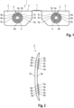
- FIG. 1 shows spectacles 1 with spectacle lenses 2 manufactured according to the first exemplary embodiment of inventive spectacle lens in a plan view.
- the spectacle lenses 2 can be regarded as representative for the spectacle lens design of the first exemplary embodiment.
- Figure 2 shows one of the spectacle lenses 2 in a side view.
- the spectacles 1 comprise two spectacle lenses 2, one for the right eye of the wearer and one for the left eye of the wearer.
- the two spectacle lenses 2 are mounted in a spectacle frame 3 and separated by the bridge 7 of the spectacle frame 3.
- Each of the spectacle lenses 2 comprises an aperture 4 which forms a clear zone for viewing objects.
- the aperture 4 is circular in shape in the present exemplary embodiment.
- the aperture 4 provides for far vision full correction. This means that independent of the distance the viewed object is located the wearer may (assisted by accommodation) clearly view, i.e. in the center area of the retina (foveal region) a sharp focus may be generated.
- the front surfaces 2a of the spectacle lenses 12 are spherical in the present exemplary embodiment.
- ring-shaped focusing structures 5a, 5b, 5c, 5d, 5e are applied in the peripheral zone 5 of the spectacle lens 2.
- Applying the ring-shaped focusing structures 5a, 5b, 5c, 5d, 5e can be done by any of the fabrication processes mentioned above.
- all five ring-shaped focusing structures 5a, 5b, 5c, 5d, 5e have an identical cross-section, which is a section of a circle.
- Each contiguous connection 6a, 6b, 6c, 6d forms a line-shaped scattering center and can, therefore be seen as a line-shaped diffuser.
- Each ring-shaped focusing structure 5a, 5b, 5c, 5d, 5e provides a ring-shaped focal line, which is, if the eye focuses in the center of the optical axis of the eye onto the retinal surface, peripherally myopic defocused as compared to the focus in the central region of the retina.
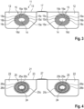
- FIG. 3 shows spectacles 11 with spectacle lenses 12 manufactured according to the second exemplary embodiment of the inventive spectacle lens in a plan view.
- the spectacle lenses 12 can be regarded as representative for the spectacle lens design of the second exemplary embodiment.
- the spectacles 11 comprise two spectacle lenses 12, one for the right eye of the wearer and one for the left eye of the wearer.
- the two spectacle lenses 12 are mounted in a spectacle frame 13 and separated by the bridge 17 of the spectacle frame 13.
- Each of the spectacle lenses 12 comprises an aperture 14 which forms a clear zone for viewing objects.
- the aperture 14 of the present exemplary embodiment is elliptical in shape and provides for far vision full correction. This means that independent of the distance the viewed object is located the wearer may (assisted by accommodation) clearly view, i.e. in the center area of the retina (foveal region) a sharp focus may be generated.
- the front surfaces of the spectacle lenses 12 are spherical in the present exemplary embodiment.
- the five ring-shaped focusing structures 15a, 15b, 15c, 15d, 15e are applied to the back surfaces of the spectacle lenses in the peripheral zones 15 of the spectacle lenses 12.
- the five ring-shaped focusing structures 15a, 15b, 15c, 15d, 15e of the second exemplary embodiment are elliptical in shape and have identical cross-sections, which is a section of a circle in the present exemplary embodiment.
- Each spectacle lens 12 may be produced by any of the fabrication processes mentioned above.
- All ring-shaped focusing structures 15a, 15b, 15c, 15d, 15e are contiguously connected to their respective inwardly and outwardly neighboring ring-shaped focusing structures 15a, 15b, 15c, 15d, 15e.
- Each of the contiguous connection 16a, 16b, 16c, 16d forms a ring-shaped scattering center and can, therefore be seen as a ring-shaped diffuser.
- Each ring-shaped focusing structure 15a, 15b, 15c, 15d, 15e provides a ring-shaped elliptical focal line, which is, if the eye focuses in the center of the optical axis of the eye onto the retinal surface, peripherally myopic defocused as compared to the focus in the central region of the retina.
- FIG. 4 shows spectacles 21 with spectacle lenses 22 manufactured according to the third exemplary embodiment of the inventive spectacle lens in a plan view.
- the spectacle lenses 22 can be regarded as representative for the spectacle lens design of the third exemplary embodiment.
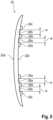
- Figure 5 shows one of the spectacle lenses 22 in a side view.
- the spectacles 21 comprise two spectacle lenses 22, one for the right eye of the wearer and one for the left eye of the wearer.
- the two spectacle lenses 22 are mounted in a spectacle frame 23 and separated by the bridge 27 of the spectacle frame 23.
- Each of the spectacle lenses 22 comprises an aperture 24 forming a clear zone of the spectacle lens 22.
- the aperture 24 of the present exemplary embodiment is elliptical in shape and provides for far vision full correction. This means that independent of the distance the viewed object is located the wearer may (assisted by accommodation) clearly view, i.e. in the center area of the retina (foveal region) a sharp focus may be generated.
- the front surfaces 22a of the spectacle lenses 22 are spherical.
- three ring-shaped focusing structures 25a, 25b, 25c are applied to the back surfaces 22b of the spectacle lenses 22.
- the three ring-shaped focusing structures 25a, 25b, 25c are elliptical in shape and are spaced by two ring-shaped diffusers 26a, 26b having a width designated by "w" in Figure 5 .
- Each spectacle lens 22 may be produced by casting.
- the ring-shaped diffusers 26a, 26b may be produced by means of a laser generating a plurality of point-shaped depressions similar to those disclosed, e.g., in WO 2010/075319 A2 , WO 2918/026697 A1 , WO 2019/152438 A1 and WO 2020/014613 A1 , respectively.
- all three ring-shaped focusing structures 25a, b 25c have an identical cross-section, which is a section of a circle.
- Each ring-shaped focusing structure 25a, 25b, 25c provides a ring-shaped elliptical focal line, which is, if the eye focuses in the center of the optical axis of the eye onto the retinal surface, peripherally myopic de-focused as compared to the focus in the central region of the retina.
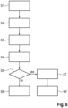
- a first step data from a prescription is received where the prescription includes a summary of the dioptric powers necessary for correcting a diagnosed refractive error.
- the prescription contains at least a value "sph” for sphere.
- values for "cyl” for cylinder and a value "axis” for the axis of the cylinder may also contain values for "cyl” for cylinder and a value "axis” for the axis of the cylinder.
- Further values may also present in the prescription like, for example a prism value and a corresponding base value.
- the prescription also contains a value for an additional power, which shall be used for providing a myopic defocus.
- the values contained in the prescription are based on a measurement performed by an eye care professional with an ametropic person, where the measurement provides for refraction data relating to the eyes of the ametropic person.
- the refraction data may either be objective refraction data, i.e. refraction data measured objectively by means of a refractometer or the like, or subjective refraction data.
- this data may be collected by letting the ametropic person look at a text or at optotypes with different sizes while trying various test lenses until the ametropic person experiences a satisfying visual acuity.
- a spectacle lens design with a focal power that provides a focused image on the fovea (assisted by accommodation) when the wearer looks through the spectacle lens worn according to an as-worn position.
- the focal power would be negative to shift the focus, which would without correction be located in front of the fovea, to the fovea.
- a correction for distance vision can be achieved.
- step S3 a focal power is determined, which leads to a focus in front of the fovea.
- This focal power can be considered as an additional power added to the focal power determined in step S2.
- This additional power when added to the focal power determined in step S2, provides the myopic defocus.
- ring-shaped focusing structures are determined which are to be present in the peripheral zone of the spectacle lens and surround an aperture without focusing structures. As the aperture is free of the ring-shaped focusing structures it provides the focal power determined in step S2.
- Determining the ring-shaped focusing structures in step S4 includes determining width and diameter of the ring-shaped focusing structures as well as their cross-sectional shape. Moreover, step S4 includes determining the number of focusing structures of which at least two will be present, and the distance between the focusing structures. Examples for suitable focusing structures have been descripted with respect to figures 1 to 5 .
- the distance between the ring-shaped focusing structures may be determined to be zero, which means that neighboring focusing structures contiguously adjoin each other.
- the circular line at which the ring-shaped focusing structures adjoin each other is a relative sharp line, which acts as a line-shaped scattering center and, thus, as a line-shaped diffuser.
- step S5 the method proceeds immediately to step S6 in case the distance between neighboring ring-shaped focusing structures determined in step S4 is zero.
- step S6 suitable data is generated which represents the spectacle lens design and allows manufacturing a spectacle lens with the focal power determined in step S2 the additional power determined in step S3 and the ring-shaped focusing structures determined in step S4.
- step S5 initiates a step S7 in which suitable scattering centers for the area between the neighboring ring-shaped focusing structures are determined.
- the scattering centers may, for example, be in the form of point-shaped or line-shaped depressions which may, for example, be formed by a laser.
- step S6' data is generated which represents the spectacle lens design and allows for manufacturing a spectacle lens with a focal power determined in step S2, the additional power determined in step S3, the ring-shaped focusing structures determined in step S4 and the scattering centers determined in step S7.
- step S11 the data generated in step S6 or step S6' of the method of providing a spectacle lens design for at least retarding myopia progression is received.
- step S12 a single vision spectacle lens is formed which provides the focal power determined in step S4 of the method of providing a spectacle lens design for at least retarding myopia progression.
- This single vision lens can, for example, be manufactured from a semi-finished blank, which includes an already finished front surface. The back surface of the semi-finished blank is then machined so that the semi-finished blank becomes the single vision spectacle lens with the requested focal power.
- a mold is set on the back surface of the single vision spectacle lens.
- the molding surface of the mold represents the negative shape of the ring-shaped focusing structures determined in step S4 of the method of providing a spectacle lens design for at least retarding myopia progression. It is set on the back surface of the single vision spectacle lens and then the ring-shaped focusing structures are formed on the back surface of the single vision spectacle lens by injection molding or any other suitable molding process. After the molding process a polishing process for removing any ridges remaining from the molding process may be performed.
- applying the ring-shaped focusing structures to the back surface of the single vision spectacle lens does, however, not need to be done by means of a molding process.
- Other processes such as, for example swelling processes like oleic acid swelling or additive manufacturing processes like inkjet printing may also be used.
- the scattering centers determined in step S7 of the method of providing a spectacle lens design for at least retarding myopia progression are introduced into the annular zone between the neighboring ring-shaped focusing structures.
- This can be done by any suitable method, for example by means of a laser generating point-shaped or line-shaped depressions in the back surface of the single vision spectacle lens between the neighboring ring-shaped focusing structures.
- a single vision spectacle lens is formed in the exemplary embodiment this embodiment provides the opportunity to manufacture a stockpile of single vision lenses with different focal powers to which ring-shaped focusing structures are applied on demand.
- first forming a single vision spectacle lens and then applying the ring-shaped focusing structures is not mandatory.
- the ring-shaped focusing structures are formed by a material removing process together with the rest of the back surface of the single vision spectacle lens stockpiling of single vision lenses to which ring-shaped focusing structures are applied on demand is, however, not possible.
- the concepts of the present invention have been described with respect to exemplary embodiments thereof for illustrating the invention.
- a person skilled in the art realizes that the concepts of the present invention can be implemented by variants of the exemplary embodiments.
- shape, number and cross-section of the ring-sized-focusing structures may differ from those described in the exemplary embodiments.
- a person skilled in the art can envisage other manufacturing techniques for providing the ring-shaped focusing structures.
- instead of forming the ring-shaped focusing structures on the front or back surface of the spectacle lens it would also be possible to provide, in the spectacle lens, ring-shaped zones with a refractive index that differs from the refractive index of the rest of the spectacle lens in order to provide the ring-shaped focusing structures.
- the ring-shaped focusing structures would be present in the spectacle lens rather than on a surface of the spectacle lens. Therefore, the present invention shall not be limited by the exemplary embodiments but only by the appended claims.
Landscapes
- Health & Medical Sciences (AREA)
- Ophthalmology & Optometry (AREA)
- Physics & Mathematics (AREA)
- Engineering & Computer Science (AREA)
- General Health & Medical Sciences (AREA)
- General Physics & Mathematics (AREA)
- Optics & Photonics (AREA)
- Manufacturing & Machinery (AREA)
- Mechanical Engineering (AREA)
- Eyeglasses (AREA)
- Prostheses (AREA)
Description
- The present invention relates to a spectacle lens, in particular a single vision spectacle lens, to be positioned relative to the eye of a wearer according to a given as-worn position, to a data set comprising a numerical representation of the spectacle lens configured for the purpose of a use of the numerical representation of the spectacle lens for a manufacture of the spectacle lens, or data containing computer-readable instructions for controlling one or more manufacturing machines in order to produce the spectacle lens, and to a method of manufacturing such a spectacle lens. In addition, the invention relates to a computer-implemented method of providing a spectacle lens design for at least retarding myopia progression based on measured eye-data.
- The prevalence of myopia (short sightedness) is increasing rapidly. Myopia significantly increases the risk of retinal detachment, (depending on the level of myopia), posterior cataract and glaucoma. The optical, visual and potential pathological effects of myopia and its consequent inconvenience and cost to the individual and community, makes it desirable to have effective strategies to slow the progress, or prevent or delay the onset of myopia, or limit the amount of myopia occurring in both children and young adults.
-
WO 2005/055891 A1 andWO 2007/092853 A2 , however, disclose that peripheral retinal image (i.e. peripheral vision) plays a major role in determining overall eye length, and is an effective stimulus that promotes peripheral and total eye growth that results in axial elongation, an overall increase in eye size and myopia. - In a key experiment described in
WO 2005/055891 A1 , primates were reared with annular diffusing lenses placed in front of the eye. The annular diffusing lenses allowed light rays from on axis, central field objects to reach the eye unobstructed. The same annular diffusing lenses scattered or diffused light rays from off-axis, peripheral field objects. This scattering induced form deprivation only to off-axis visual objects in the peripheral field, while maintaining clear vision for the central field. It is known to vision scientist working on myopia development that form deprivation applied to the entire visual field (or central field) of the eye induces axial growth leading to myopia. In the experiment disclosed inWO 2005/055891 A1 , involving form deprivation to only the peripheral field, the eye also developed myopia due to axial elongation and eye growth. - In an extension to the experiment described in
WO 2005/055891 A1 , the annular diffusing lenses were removed from some eyes following development of substantial amounts of myopia. When the annular diffusing lenses were removed, the amount of myopia in the primates decreased. - Further, in a parallel extension to the experiment, for other eyes, in addition to removal of the annular diffusing lenses following development of substantial amounts of myopia, central vision of the primate's eye was eliminated, by using an Argon (blue-green) laser to ablate the macular portion of the retina by photocoagulation, essentially blinding central vision while sparing peripheral vision. Even when on-axis central, foveal vision was interrupted in this manner, the decrease in myopia remained similar to when central vision was not disrupted.
- Based on learning from these experiments that demonstrate that the peripheral retinal image (i.e. peripheral vision) plays a major role in determining overall eye length, and is an effective stimulus that promotes peripheral and total eye growth that results in axial elongation, an overall increase in eye size and myopia,
WO 2005/055891 A1 discloses a method of abating, retarding or eliminating the progression of myopia in an individual by controlling off-axis aberrations through manipulating the curvature of field of a visual image in a predetermined fashion and ultimately altering, reducing or eliminating eye axial elongation. In this method by which myopia progression may be retarded (and in many cases, halted or reversed) an optical device having a predetermined off-axis aberration-controlled design that abates, retards or eliminates eye growth while simultaneously providing clear central imaging is used. - The authors of
WO 2005/055891 A1 describe a method and apparatus for controlling optical aberrations to alter relative curvature of field by providing ocular apparatuses, systems and methods comprising a predetermined corrective factor to produce at least one substantially corrective stimulus for repositioning peripheral, off-axis, focal points relative to the central, on-axis or axial focal point while maintaining the positioning of the central, on-axis or axial focal point on the retina. The method and apparatuses are used to provide continuous, useful clear visual images while simultaneously retarding or abating the progression of myopia. - The authors propose e.g. an optical device, such as spectacles, contact lenses, artificial corneal devices such as on-lays and in-lays, corneal implants, anterior chamber lenses or intraocular lenses, or employing interventions, such as methods for corneal and epithelial remodeling and sculpting including orthokeratology and refractive surgery such as epikeratophakia, thermokeratoplasty, LASIK, LASEK and PRK that can provide a resultant negative relative curvature of field at the retina, and that in addition, in order to continue to provide good central visual acuity for critical visual tasks, the optical device or optical intervention should ensure good focus of central field image to the retina.
- The documents
WO 2005/055891 A1 andWO 2007/092853 A2 disclose a suitable spectacle lens. This spectacle lens is designed such that it would generate a negative relative curvature of field on the eye. According to the authors this arrangement is advantageous over conventional under-correction approaches as the central, on-axis image point is focused sharply to the fovea enabling good visual acuity. The peripheral image points, due to the negative relative curvature of field, are focused more anteriorly, or in front (i.e. in the direction against the direction of light in the eye) of the retina. This has the effect of producing a relative under-correction to the peripheral field, which, from the experiment results, would control eye growth and axial elongation. That is, due to the more anterior location of the off-axis, peripheral field image points, stimulus to axial growth is significantly reduced, eliminated or reversed in the eye, leading to reduction or elimination of myopia development or reduction and even reversal of myopia progression. - The first versions of spectacle lenses following this approach are developed by the Carl Zeiss Vision group in cooperation with the Brian Holden Vision Institute. One of the first spectacle lens designs following this approach is e.g. disclosed in
WO 2007/041796 A1 . - Another spectacle lens design being launched under the trademark Myovision is e.g. disclosed in
WO 2009/052570 A1 . - According to Prof. Schäffel in a presentation "Individualisierte Myopiebehandlung bei Kindern - Prof. Dr. Frank Schaeffel und Dr. Hakan Kaymak (Innovationssymposium 2019)" held on January 19, 2019 in Düsseldorf Essilor markets a similar design under the trademark Myopilux.
- Further lens designs following the theory described in
WO 2005/055891 A1 are disclosed inWO 2009/129528 A1 assigned inter alia to Novartis AG. These lens designs being characterized by a peripheral optical zone surrounding a central zone. Said peripheral zone includes an incident angle with respect to the optical axis of about 30 degrees and has a positive peripheral refractive power relative to the refractive power of the central zone of that lens to thereby provide myopic peripheral defocus. DespiteWO 2009/129528 A1 indicates the suitability of said lens for spectacles, in particular, the above co-applicant points to a design targeted for a contact lens. - Well known due to market success are in particular Coopervision's contact lenses, the principle of which is e.g. disclosed in
WO 2010/129465 A1 . The ophthalmic lens disclosed therein comprises or includes a vision correction region and a myopic defocus region. In an example disclosed inWO 2010/129465 A1 the ophthalmic lens is a contact lens comprises an annular zone with three subrings which surrounds a central zone. While two of the sub-rings belong to the myopic defocus region the third sub-ring, which separates the two sub-rings belonging to the myopic defocus region, belongs to the vision correction region, together with the central zone. The vision correction region and the myopic defocus region define an optic zone of the contact lens. The optic zone is circumscribed by a non-optical peripheral zone which extends from an outer perimeter of the optic zone to a peripheral edge zone of the contact lens. The optic zone comprises or consists of a plurality of concentric rings circumscribing a central circular zone. - The central zone of the contact lens is circular or substantially circular and may have a distance optical power and a diameter greater than 2.0 mm. The diameter of the central zone can be determined by measuring a straight line through the optic axis to opposing perimeter boundaries of the central zone in a two-dimensional front plan view of the contact lens.
- Similar designs allegedly being suitable for contact lenses and spectacle lenses are also disclosed in
US 2016/054588 A1 ,US2017/276961 A1 andUS 2019/227342 A1 assigned to Johnson & Johnson. - In particular,
US 2019/0227342 A1 discloses an ophthalmic lens having a center zone with a negative power for myopic vision correction; and at least one treatment zone surrounding the center zone. The at least one treatment zone having a power profile comprising an ADD power. The at least one treatment zone has a surface shape composing a portion of a generally toroidal shape. The at least one treatment zone is arranged as to form a continuous surface with the center zone. As an example, the portion of the toroidal shape may be derived from a torus (e.g., spheroidal torus), wherein a slice through the surface of the spheroidal torus to generate the portion of the toroidal shape comprises a right circular conical surface with the principal axis of the cone coincident with the axis of rotation about which the torus is generated. The treatment zone may be configured to result in a ring focus. A position of the focal ring may be dependent upon the optical power of the treatment zone. - Optical function of a radially concentric multizone ophthalmic lens that serves at least a spherical correction purpose according to
US 2019/0227342 A1 is most generally derived from a front and back surface. One of these surfaces may be spheroidal or ellipsoidal in nature. The other surface typically has a spheroidal or ellipsoidal cap and then one or more curved portions, each of which is the surface of a spheroidal or ellipsoidal frustum ("zone") that is symmetrically arranged so as to form a continuous surface. The zones may be radially concentric and optically coaxial about a common axis. - Each frustum may be created by sectioning a spheroid or ellipsoid of appropriate size and shape to achieve the desired optical power, perpendicular to the principal axis of such spheroid or ellipsoid. In some cases, a transitional region (e.g., an optically dysfunctional) may be required to allow the individual zones to form a continuous surface. For myopia treatment, some of the zones will generally produce a more positive wavefront derivative than the zone or zones devoted to correct distance vision, where the wavefront derivative is taken with respect to the radial distance from the principal axis (dW/dr). Rays of light parallel to the common axis and passing through the zones will come to a principal focus for each zone, and these foci will be located on the common axis for rotationally symmetric zones. When the ophthalmic lens is used to correct vision and where one or more of the zones have principal foci of different focal length, the image formed at the retina of the eye may come along with ghosting or haloes, leading to degradation of vision.
-
US 2019/0227342 A1 discloses embodiments having a zone (or replacing a designed zone of the lens) with a surface shape derived from a toroidal shape (e.g., spheroidal torus) or, in the case of replacing multiple zones, from one or more tori. As an example, the portion of the toroidal shape to be utilized may be derived from a torus (e.g., a spheroidal torus), after making a slice in the shape of the surface of a right circular cone through the surface of the spheroidal torus wherein the principal axis of the cone is coincident with the axis of rotation about which the torus is generated. The portion of the torus forming part of the lens surface is so arranged as to form a continuous surface with other zones of the lens or being joined by an optically dysfunctional, transition region to allow the individual zones to form a continuous surface. - Other slices (conical or otherwise) than outlined in the document are indicated as being suitable to be used.
- Hong Kong Polytechnic University and Hoya recently disclosed a different kind of spectacle lenses following the general approach described iin
WO 2005/055891 A1 . Hoya sells such spectacle lenses under the trademark MyoSmart. The spectacle lenses are known as MSMD (multi segment myopic defocus) lenses. The respective technical concept is known as D.I.M.S. (Defocus Incorporated Multiple Segments) technology. Details are, for example, disclosed under https://www.hoYavision.com/en-hk/discover-products/for-spectacle-wearers/special-lenses/myosmart/. Respective spectacle lenses are disclosed inUS 2017/131567 A1 . The spectacle lenses comprise a central zone providing full correction and a plurality of microlenses/lenslets surrounding the central zone and providing an additional power of e.g. approximately 3.5 D. A similar approach is used in Essilor's Stellest spectacle lenses being described in detail inEP 3 553 594 A1EP 3 561 578 A1WO 2019/166653 A1 ,WO 2019/166654 A1 ,WO 2019/166655 A1 ,WO 2019166657 A1 ,WO 2019/166659 A1 andWO 2019/206569 A1 , respectively. The microlenses/lenslets are aspherical and have an optical power in their geometrical center which lies in the range between 2.0 dpt and 7.0 dpt in absolute value, and an optical power in their periphery which lies in the range between 1.5 dpt and 6.0 dpt in absolute value. The refractive optical power provided by the aspherical microlenses/lenslets exceeds the refractive power of the clear central zone by 0.5 dpt or more. - Also
WO 2020/014613 A1 assigned to Sightglass Vision Inc. recently disclosed a myopia control spectacle lens that may contain one or more defocus elements, i.e. a myopia control spectacle lens may contain a clear center, free of said defocus elements treating children having, or suspected of having, myopia by having the children wear spectacles with myopia control lenses provides a safe, efficient, and non-invasive method for reducing the progression of juvenile myopia. Exemplarily, the document refers to regions that comprise island-shaped lenses. -
WO 2010/075319 A2 also refers to the importance of peripheral retinal image determining myopic eye growth. The document proposes a therapeutic treatment method for preventing, ameliorating, or reversing eye-length- related disorders, the therapeutic treatment method comprising: identifying, in a patient, an eye-length-related disorder; and inducing artificial blurring of the patient's peripheral vision in order to decrease an average spatial frequency of images input to the retina of the eye past a threshold spatial frequency to inhibit further lengthening of the patient's eye. In particular, the document proposes providing the patient with spectacle lenses having a first area including a plurality of first elements selected from the group consisting of: (i) bumps on a surface of the spectacle lens; (ii) depressions on the surface of the spectacle lens; (iii) first translucent inclusions in a spectacle lens material; and (iv) first transparent inclusions in the spectacle lens material, the first transparent inclusions having a refractive index different from that of the spectacle lens material. The elements in general are point-shaped elements having a non-zero point density in a range between 0 and 8 dots per mm2. - Improvements of this kind of spectacle lenses are disclosed in
WO 2018/026697 A1 andWO 2019/152438 A1 , respectively. - In particular,
WO 2018/026697 A1 discloses a pair of eyeglasses, comprising: eyeglass frames; and a pair of spectacle lenses mounted in the frames, the spectacle lenses comprising a point pattern distributed across each spectacle lens, the point pattern comprising an array of dots spaced apart by a distance of 1 mm or less, each point having a maximum dimension of 0.3 mm or less. -
WO 2020/113212 A1 and a contrast reduction region comprising scattering centers and/or one or more lenslets for reducing image contrast -
WO 2019/152438 A1 discloses a spectacle lens, comprising: a lens material having two opposing curved surfaces; and a scattering region surrounding a clear aperture, wherein the scattering region has a plurality of spaced apart scattering centers sized and shaped to scatter incident light, the scattering centers being arranged in a pattern that includes an irregular variation in spacing between adjacent scattering centers and/or an irregular variation in scattering centers size. -
WO 2010/075319 A2 ,WO 2018/026697 A1 ,WO 2019/152438 A1 andWO 2020/014613 A1 describe spectacle lenses with artificial peripheral scattering whileWO 2020/113212 A1 andWO 2020180817 A1 describe spectacle lenses with a contrast reduction region comprising scattering centers and/or one or more lenslets for reducing image contrast. Introducing artificial peripheral scattering is somewhat in contradiction to the findings described inWO 2005/055891 A1 andWO 2007/092853 A2 with respect to annular diffusing lenses, however, the results of respective trials based on SightGlass Vision's DOT spectacle lenses have been disclosed to be promising. - Each microlens/lenslet of the spectacle lenses described in
US 2017/131567 A1 orEP 3 553 594 A1EP 3 561 578 A1WO 2019/166653 A1 ,WO 20191/66654 A1 ,WO 2019/166655 A1 ,WO 2019/166657 A1 ,WO 2019/166659 A1 andWO 2019/206569 A1 , respectively, and being described in detail above, must separately be produced. Therefore, there is a need for spectacle lenses which may be produced by a simplified fabrication technology but still providing optical properties resembling those described in the foregoing to control myopia progression. -
CN 111103701 A discloses ring-shaped focusing structures with a distance between two neighboring ring-shaped focusing structures being in the range between 0.5 to 3 mm. - From
US 2019/0227342 A1 , which is regarded as closest state of the art, contact lenses and spectacle lenses using a torus instead of. microlenses/lenslets for providing a myopic defocus are known. However one very feature disclosed inUS 2019/0227342 A1 is that the portion of the torus forming part of the lens surface is so arranged as to form a continuous surface with other zones of the lens or being joined by an optically dysfunctional, transition region to allow the individual zones to form a continuous surface. To achieve the continuity a specific adaption in the design of the surface of the contact lens or spectacle lens is necessary, which means amending the whole surface of the contact lens or spectacle lens as compared to a surface without the torus. In addition, also as specific adaptions in production are necessary. Moreover, in cease of more than one torus the zones between the tori do not contribute in at least retarding myopia progression. - It is a first objective of the present invention to provide a spectacle lens with at least two ring-shaped focusing structures having focal powers that provide a myopic defocus which may be produced by a simplified fabrication technology, do not require amending the whole surface of the spectacle lens design and contribute in at least retarding myopia progression also by means of zones between the ring-shaped focusing structures, as well as providing a data set comprising a numerical representation of the spectacle lens configured for the purpose of a use of the numerical representation of the spectacle lens for a manufacture of the spectacle lens, or data containing computer-readable instructions for controlling one or more manufacturing machines in order to produce the spectacle lens.
- It is a second objective of the present invention to provide a method of manufacturing a spectacle lens which allows producing spectacle lenses with at least two ring-shaped focusing structures having focal powers that provide a myopic defocus without the requirement of amending the whole surface of the spectacle lens.
- It is a third objective of the present invention to make available a computer-implemented method of providing a spectacle lens design with at least two ring-shaped focusing structures having focal powers that provide a myopic defocus for at least retarding myopia progression based on measured eye-data which can be performed outgoing from a simple spectacle lens without amending the whole surface of the spectacle lens design and allows for a simplified fabrication technology for the spectacle lens.
- The first objective is achieved with a spectacle lens as claimed in claim 1 and a data set as claimed in
claim 5. The second objective is achieved by a method of manufacturing a spectacle lens as claimed in claim 6 and the third objective is achieved by a computer-implemented method of providing a spectacle lens design for at least retarding myopia progression as claimed in claim 10. The depending claims claim further developments of the invention. - The following definitions are used within the scope of the present description:
- In the context of the present specification, the term "additional power" applies to a focal power that is added to the focal power of a spectacle lens, where the focal power of a spectacle lens provides, assisted by accommodation, a focused image on the fovea and the additional power, when added to the focal power of a spectacle lens, provides for a myopic defocus. The additional power must not be confused with the addition power of a progressive addition lens.
- In the context of the present specification, the term "aperture" applies to a zone of a spectacle lens that is surrounded by one or more ring-shaped structures.
- The as-worn position is the position, including orientation, of the spectacle lenses relative to the eyes and face during wear (DIN ISO 13666:2019, section 3.2.36). The as-worn position is determined by the as-worn pantoscopic angle, the as-worn face form angle and the vertex distance. The as-worn pantoscopic angle is the vertical angle between the horizontal and the perpendicular to a reference line passing through the apex of the grooves of the upper and lower rims of the frame in the vertical plane containing the primary direction (DIN ISO 13666:2019, section 3.2.37), where the primary direction is the direction of the line of sight, usually taken to be the horizontal, to an object at an infinite distance measured with habitual head and body posture when looking straight ahead in unaided vision (DIN ISO 13666:2019, section 3.2.25) and the line of sight is the ray path from the point of interest (i.e. point of fixation) in object space to the centre of the entrance pupil of the eye and its continuation in image space from the centre of the exit pupil to the retinal point of fixation (generally the foveola) (DIN ISO 13666:2019, section 3.2.24). Typical values of the as-worn pantoscopic angle lie in the range between -20 and +30 degree. The as-worn face form angle is the horizontal angle between the primary direction and the perpendicular to a reference line passing through the apex of the grooves of the nasal and temporal rims of the frame in the horizontal plane containing the primary direction (DIN ISO 13666:2019, section 3.2.38). Typical values of the as-worn face form angle lie in the range between -5 and +30 degree. The vertex distance is the horizontal distance between the back surface of the spectacle lens and the apex of the cornea, measured with the eyes in the primary position (DIN ISO 13666:2019, section 3.2.40), where the primary position is the position of the eye when looking in the primary direction (DIN ISO 13666:2019, section 3.2.26). Typical valued of the vertex distance lie in the range between 5 mm and 30 mm. The as-worn position may be an individual as-worn position determined for a specific individual or a generic as-worn position determined for a defined group of wearers.
- In the context of the present invention, a central zone is a zone of a spectacle lens or a spectacle lens design that is surrounded by a surrounding zone the optical properties of which differ from the surrounded central zone.
- In the context of the present specification, the term "clear zone" applies to a zone of a spectacle lens design or a spectacle lens that provides neither a myopic defocus nor a diffusion in foveal vision when a wearer looks through the clear zone with the spectacle lens being positioned according the specified as-worn position. Furthermore, a clear zone allows for achieving, if necessary assisted by accommodation, a focused image on the fovea. There may be zones of a spectacle lens design or a spectacle lens that do neither provide a myopic defocus nor a diffusion in foveal vision when a wearer looks through the respective zone but show a residual astigmatic error leading to a blurred image. Such a zone is not regarded as a clear zone in the meaning used in the present specification.
- In the context of the present specification, the term "contact line" applies to a contact zone between two structures contiguously adjoining each other where the geometry surfaces of the structures is such that it is not continuously differentiable in a direction crossing the contact zone.
- In optics, a diffuser (also called a light diffuser or optical diffuser) is an optical element that is made of any material that diffuses or scatters light in some manner to transmit soft light. Diffuse light can be easily obtained by reflecting light from a white surface, while more compact diffusers may use translucent material, including ground glass, Teflon, holographs, opal glass, and greyed glass. Scattering may be achieved by scattering centers which may be point-shaped, examples of which are, e.g., disclosed in
WO 2010/075319 A2 ,WO 2018/026697 A1 ,WO 2019/152438 A1 andWO 2020/014613 A1 , respectively. Scattering centers may also be line-shaped, e.g. in case of a contiguous connection having a not continuous transition and/or a not smooth transition. - The term "Focal power" is a collective term for the spherical vertex power, which brings a paraxial pencil of parallel light to a single focus (and which is usually considered in the prescription by the "sphere" value or, abbreviated, "sph", and the cylindrical vertex power of a spectacle lens, which brings a paraxial pencil of parallel light to two separate line foci mutually at right angles (DIN ISO 13666:2019, section 3.10.2) and which is usually considered in the prescription by the "cylinder" value or, abbreviated, "cyl". The "vertex power" is the reciprocal of the paraxial vertex focal length (DIN ISO 13666:2019, section 3.10.7). Within the scope of the present description, a beam is to be considered to be a paraxial pencil of rays if its diameter does not exceed 0.05 mm, in particular 0.01 mm.
- The term "myopic defocus" refers to a situation in which light focusses in front of the fovea by such a distance that a focused image on the fovea cannot be achieved, even when assisted by accommodation. A peripheral myopic defocus is a myopic defocus that is present outside the visual field outside the fovea.
- In the context of the present invention, a peripheral zone shall be understood as a zone of a spectacle lens or a spectacle lens design which surrounds a central zone and corresponds to peripheral vision when a wearer of the spectacle lens looks through the central zone.
- The term "prescription" denotes a summary in which the dioptric powers necessary for correcting a diagnosed refractive error are specified in the form of suitable values. In the case of spherical power, the prescription may contain a value "sph" for sphere. In the case of astigmatic power, the prescription can contain values "cyl" for cylinder and "axis" for axis, and, in the case of prismatic power, the prescription can contain prism and base values. Moreover, the prescription may contain further values, for example the "add" value in the case of multifocal spectacle lenses, said "add" value specifying the difference between the vertex power in the near portion of the spectacle lens and in the distance portion of the spectacle lens. A value "PD" for the interpupillary distance may also be contained in the prescription.
- In the context of the present invention, the expression "representation of a spectacle lens design" refers to an implementation of a spectacle lens having the respective design features (physical representation of the spectacle lens design) or to a numerical data set describing the design features (numerical representation of the spectacle lens design). For example, such a data set may be stored in a memory of a computer or on a computer-readable (particularly non-transitory) storage medium. In addition, the data set may be retrievable from a data network like, for example, the internet or a local area network (LAN). A dataset resembling a representation of a progressive spectacle lens design may include, in particular, a description of the geometric shape and the medium of the progressive spectacle lens. Such a description can e.g. include a mathematical description of the front surface, the rear surface, the arrangement of these surfaces in relation to one another (including the thickness) and the edge delimitation of the progressive spectacle lens as well as the refractive index distribution of the medium of which the progressive lens is to be made. The representation can be in coded or even in encrypted form. The term medium here means the material(s) or the substance the spectacle lens is made of.
- The representation of the progressive spectacle lens design may in addition or alternatively include computer-readable instructions for controlling one or more manufacturing machines (e.g. casting, grinding, milling, lapping and/or polishing machines) in order to produce a spectacle lens having the respective design features.
- A structure shall be considered as ring-shaped if surrounds a structure-free zone and there is a path within the structure which runs from a starting point within the structure around the structure-free zone and to the starting point again.
- In the context of the present specification, the term "ring-shaped focusing structures" applies to structures providing a ring-shaped focal line as well as to structures providing a plurality of (e.g. equidistantly arranged and preferably mainly line-shaped or point-shaped) foci along a ring-shaped line. Such ring-shaped focusing structures may e.g. comprise structures similar to those described in
EP 3 553 594 A1EP 3 561 578 A1WO 2019/166653 A1 ,WO 2019/166654 A1 ,WO 2019/166655 A1 ,WO 2019166657 A1 ,WO 2019/166659 A1 andWO 2019/206569 A1 , respectively, or structures similar to those disclosed inUS 2016/054588 A1 ,US 2017/227788 A1 ,US 2017/276961 A1 ,US 2019/227342 A1 ,WO 07/041796 A1 WO 09/129528 A1 WO 10/129465 A1 - The term "semi-finished blank" refers to a piece of optical material with one optically finished surface for the making of a spectacle lens (DIN ISO 13666:2019, section 3.8.1)
- A spectacle lens is an ophthalmic lens worn in front of, but not in contact with, the eyeball (DIN ISO 13666:2019, section 3.5.2), where an ophthalmic lens is a lens intended to be used for purposes of measurement, correction and/or protection of the eye, or for changing its appearance (DIN ISO 13666:2019, section 3.5.1)
- The term optical spectacle lens design is used to denominate the calculated/predetermined or defined optical properties of a spectacle lens, typically for a predetermined specific wearer, taking into consideration a position/arrangement of the spectacle lens relative to a model of an eye of the wearer of the spectacle lens, a position/arrangement of a model of an object to be viewed by the wearer of the spectacle lens for a specific use condition of the spectacle lens as well as a model of the physiological visual properties of the wearer of the spectacle lens.
- Particularly, the optical spectacle lens design may comprise a distribution of optical power across an effective area of a spectacle lens as perceived by a predetermined wearer of the spectacle lens for a predetermined as-worn position relative to the wearer's (model) eye and a predetermined object distance model. The calculation of the distribution of the optical power is based on the distance and orientation of the spectacle lens relative to the model eye, the distance and orientation of the spectacle lens relative to the model object as well as physiological parameters of the spectacle wearer such as the wearer's visual deficiencies, namely e.g. the wearer's ametropia, the wearer's ability to accommodate and the wearer's pupillary distance.
- The term geometric spectacle lens design means the geometry of the spectacle lens providing the calculated optical properties of a spectacle lens described in the forgoing for the spectacle wearer.
- The term target optical spectacle lens design means, a draft optical spectacle lens design, the optical properties of which correspond to or are equal to target optical properties. The term actual optical spectacle lens design means calculated optical properties of a spectacle lens being received as a result of an optimization process/calculation aiming to achieve the target optical spectacle lens design as close as possible. Such an optimization process/calculation in particular for progressive spectacle lenses or customized single vision lenses is e.g. disclosed in Werner Köppen: Konzeption und Entwicklung von Progressivgläsern, in Deutsche Optiker Zeitung DOZ 10/95, S. 42-46.
- Such optical or geometric spectacle lens designs may be stored on a computer-readable (e.g. non-transitory and/or electronic and/or optical) data carrier. Moreover, spectacle lenses manufactured according to the spectacle lens design can be considered physical representations of the spectacle lens design.
- Essential steps of an example of a method for designing a spectacle lens are outlined in the following:
In a first step, individual user data or application data of the spectacle wearer are recorded. This includes the acquisition of (physiological) data that can be assigned to the spectacle wearer and the acquisition of usage conditions under which the spectacle wearer will wear the spectacles to be designed. - The physiological data of the spectacle wearer may include e.g. the wearer's ametropia and the wearer's ability to accommodate, which are determined by means of a refraction measurement and which are regularly included in a prescription in the form of prescription values for sphere, cylinder, axis, prism and base as well as addition. Furthermore, e.g. the pupillary distance and the pupil size were determined under different lighting conditions. The age of the wearer has an influence on the ability to accommodate and pupil size and may therefore also be taken into consideration. The convergence behavior of the eyes results from the pupillary distance for different viewing directions and object distances.
- The conditions of use include the as-worn position of the spectacle lenses in front of the eye (usually in relation to the eye's pivot point) and the object distances for different viewing directions under which the spectacle wearer should see clearly. The seat of the spectacle lenses in front of the eye can e.g. be determined by recording the corneal vertex distance as well as anterior and lateral inclination. These data are included in an object distance model, for which a ray tracing method can be applied.
- In a subsequent step, a draft design for the spectacle lens with a large number of evaluation points is determined on the basis of this recorded data. The draft design includes target optical properties for the spectacle lens at the respective evaluation point. The target properties include e.g. the permissible deviation from the prescribed spherical and astigmatic power, taking into account the addition, distributed over the entire spectacle lens, as specified by the arrangement of the lens in front of the eye and the underlying distance model.
- Furthermore, a design of surface geometries for the front and back surfaces as well as a design for a refractive index distribution over the entire spectacle lens are specified. E.g. the front surface can be selected as a spherical surface and the back surface as a varifocal surface. Both surfaces could also initially be selected as spherical surfaces. The choice of surface geometry for the first draft generally only determines the convergence (speed and success) of the optimization method used. It should be assumed, for example, that the front surface is to retain the spherical shape and the back surface is given the shape of a varifocal surface.
- In a further step, the course of main rays is determined through the large number of evaluation points. Possibly, a local wavefront can be established for each of the main rays in a vicinity of the respective main ray. According to Werner Köppen: Design and Development of Progressive Lenses, in Deutsche Optiker Zeitung DOZ 10/95, pp. 42-46, the number of evaluation points is usually in the range between 1000 and 1500.
EP 2 115 527 B1EP 2 383 603 B1 - In a subsequent step, the above optical properties of the spectacle lens at the evaluation points are determined by determining an influence of the spectacle lens on the beam path of the main rays and, if necessary, the local wavefronts in the vicinity of the respective evaluation point.
- In a further step, the design of the spectacle lens is evaluated depending on the determined optical properties and the individual user data. The back surface geometry and as the case may be the refractive index distribution of the design of the spectacle lens may be modified by minimizing a target function such as e.g.

- In other words, the local surface geometry of the back surface and as the case may be the local refractive index of the spectacle lens in the respective visual beam path are modified by the evaluation points until a termination criterion is met.
- According a first aspect of the invention, a spectacle lens to be positioned relative to the eye of a wearer according to a given as-worn position is provided. The as-worn position can be an individual as-worn position or a generic as-worn position. The spectacle lens design includes:
- An aperture which has a focal power, and, in particular, has a focal power that provides a focused image on the fovea, when the spectacle lens is positioned according to the as-worn position,.
- At least two ring-shaped focusing structures surrounding the aperture, wherein neighboring ring-shaped focusing structures each provide a ring shaped focal line. In particular, the ring-shaped focusing structures have focal powers that provide a myopic defocus when the spectacle lens is positioned according to the as-worn position,. The myopic defocus can, in particular, be provided by designing the ring-shaped focusing structures such as to provide a higher focal power than the focal power provided by the aperture. Preferably the ring-shaped focusing structures provide an additional power to the focal power of the aperture so that the focal power of the spectacle lens in the area of a ring-shaped focusing structures exceeds the focal power of the spectacle lens in the area of the aperture by at least 0.5 D. Typically the ring-shaped focusing structures provide an additional power in the range from 0.5 dpt to 5 dpt.
- A ring-shaped diffuser is arranged between the ring-shaped focusing structures. Neighboring ring-shaped focusing structures adjoin each other with a ring-shaped contact line between them which forms the ring-shaped diffuser.
- The inventive spectacle lens design may be a spectacle lens design for a single vision spectacle lens, in particular for a single vision spectacle lens with an aperture that is centered on the optical axis of the single vision spectacle lens.
- The idea of the present invention is to replace the plurality of microlenses / lenslets described, for example, in
US 2017/131567 A1 orEP 3 553 594 A1EP 3 561 578 A1WO 2019/166653 A1 ,WO 20191/66654 A1 ,WO 2019/166655 A1 ,WO 2019/166657 A1 ,WO 2019/166659 A1 andWO 2019/206569 A1 by preferably concentrically arranged ring-shaped focusing structures. The ring-shaped focusing structures may be of any curved shape, for example circular or elliptical or of a similar curved shape, and may, preferably, be symmetric with respect to at least one axis. A ring-shaped focusing structure may be based on a torus-like structure or any other three-dimensional closed structure surrounding a structure-free zone which is cut in tow pieces along a straight or curved surface such that both pieces are still ring-shaped. The ring-shaped focusing structure may then be represented by one of the two pieces. For example, a ring-shaped focusing structure may represent a piece of a torus or any other three-dimensional ring-shaped structure at which one arrives by cutting the torus or the other ring-shaped structure along a surface corresponding to a surface of the spectacle lens. The three-dimensional closed structure surrounding a structure-free zone on which the ring-shaped focusing structure are based may in particular be symmetric in two planes perpendicular to each other like, for example, a ring torus, which shows rotational symmetry in such planes. The cross-section of one ring-shaped focusing structure is preferably identical along the complete ring. The cross-sections of at least two ring-shaped focusing structures have preferably the same shape (e.g. being a circular or elliptical section) and preferably have identical size. The shapes of the cross-sections of all ring-shaped focusing structures are preferably identical. In addition, the size of all cross-sections of all ring-shaped focusing structures may be identical. - The invention provides a spectacle lens design in which not only the ring-shaped focusing structures but also the zones between ring-shaped focusing structures are effective in at least retarding myopia progression. While the ring-shaped focusing structures are effective in at least retarding myopia progression due to providing a myopic defocus the ring-shaped zone between two ring-shaped focusing structures is effective in at least retarding myopia progression due to reducing contrast by means of the diffuser being formed in this ring-shaped zone. Moreover, the inventive spectacle lens design allows for manufacturing a corresponding spectacle lens in a two-step process by providing a spectacle lens without the ring-shaped focusing structures and then applying the ring-shaped focusing structures to a surface of the spectacle lens. This can be done without amending the whole surface of the spectacle lens design. In addition, with using ring-shaped focusing structures the number of structure elements to be applied on the surface is considerably reduced as compared to using microlenses/lenslets. Hence, the fabrication technology is considerably simplified in case of producing a spectacle lens based on the inventive spectacle lens design as compared to the spectacle lens designs according to the state of the art.
- With the inventive spectacle lens, the ring-shaped diffuser is formed simultaneously with forming the ring-shaped focusing structures as the contact line forms a scattering center. Hence, an additional step of forming the diffuser is not necessary.
- In an advantageous further development of the inventive spectacle lens design the at least two of the ring-shaped focusing structures provide a myopic defocus at the same distance to the fovea. By this measure, ghosting and halos in peripheral vision can be avoided.
- In the inventive spectacle lens design the ring-shaped focusing structures and the diffuser may be present at the back surface of the spectacle lens. This allows for a manufacturing process in which a semi-finished blank is used. Such a semi-finished blank typically has an already finished front surface and is only machined on the back surface in order to manufacture a spectacle lens. Having the ring-shaped focusing structures at the back surface of the spectacle lens design makes it possible to integrate the application of the ring-shaped focusing and the diffuser structures into a manufacturing process using a semi-finished blank.
- According to a second aspect of the invention, a method of manufacturing a spectacle lens to be positioned relative to the eye of a wearer according to a given as-worn position is provided. The method includes:
- Forming a part of a spectacle lens such as to provide a focal power, in particular a focal power that forms a focused image on the fovea in the as-worn position.
- Forming at least two ring-shaped focusing structures with focal powers such that the at least two ring-shaped focusing structures surround an aperture providing said focal power. The neighboring ring-shaped focusing structures each provide a ring shaped focal line. The ring-shaped focusing structures may, in particular be formed on a surface of the spectacle lens. Typically, a myopic defocus is provided by an increased focal power of the ring-shaped focusing structures as compared to the focal power that focusses the image on the fovea.
- A ring-shaped diffuser is formed between the ring-shaped focusing structures, and the neighboring ring-shaped focusing structures are formed such as to adjoin each other with a ring-shaped contact line between them where the contact line forms the ring-shaped diffuser. Then, the ring-shaped diffuser is formed simultaneously with forming the ring-shaped focusing structures as the contact line forms a scattering center. Hence, an additional step of forming the diffuser is not necessary. However, although the number of diffusers can be increased by increasing the number of ring-shaped focusing structures, and thus the number of ring-shaped contact lines, adjoining ring-shaped focusing structures do not allow for changing the width of the diffuser. Therefore, as an alternative, the neighboring ring-shaped focusing structures may be formed at a distance to each other. Then, the ring-shaped diffuser is formed between the ring-shaped focusing structures so as to adjoin the ring-shaped focusing structures. The distance between neighboring ring-shaped focusing structures provides for an additional design parameter in the spectacle lens design, namely the width of the diffuser. However, compared to the first option this comes at the cost of an additional manufacturing step, namely with a step of forming scattering centers in the ring-shaped zone which, at the end, forms the diffuser. Producing the scattering centers may, for example, be done by means of a laser generating a plurality of point-shaped depressions e.g. similar to those disclosed in
WO 2010/075319 A2 ,WO 2018/026697 A1 ,WO 2019/152438 A1 andWO 2020/014613 A1 , respectively. - The inventive method may be used for manufacturing a single vision spectacle lens, in particular a single vision spectacle lens with an aperture that is centered on the optical axis of the single vision spectacle lens.
- The inventive method allows for manufacturing a spectacle lens with at least two ring-shaped focusing structures without amending the whole surface of the spectacle lens design. In addition, with using ring-shaped focusing structures the number of structure elements to be applied on the surface is considerably reduced as compared to using microlenses/lenslets. Hence, the inventive method allows for manufacturing spectacle lens with at least two ring-shaped focusing structures by means of a fabrication technology that is considerably simplified as compared to the state of the art.
- In order to allow integrating the application of the ring-shaped focusing structures and the diffuser into a manufacturing process using a semi-finished blank with a finished front surface the at least two ring-shaped focusing structures may be formed on the back surface of the spectacle lens.
- In a specific development of the inventive method, first a spectacle lens providing a focal power that forms a focused image on the fovea in the as-worn position is formed and then the at least two ring-shaped focusing structures are applied to a surface of said spectacle lens so as to surround an aperture of said spectacle lens which becomes the part of the spectacle lens which provides said focal power that forms a focused image on the fovea. The at least two ring-shaped focusing structures may be applied to a surface of the spectacle lens by means of one of the following processes: Molding, additive manufacturing, and swelling. This specific development of the inventive method allows for stockpiling spectacle lenses providing a focal power that forms a focused image on the fovea in the as-worn position and applying the ring-shaped focusing structures on a surface of such a stockpiled spectacle lens.
- As an alternative, the at least two ring-shaped focusing structures may be formed by means of a material removing process such as cutting. This allows for forming the part of the spectacle lens which provides said focal power that forms a focused image on the fovea and the at least two ring-shaped focusing structures in the same manufacturing step.
- According to a third aspect of the invention, a computer-implemented method of providing a spectacle lens design for at least retarding myopia progression based on measured eye-data is provided. The method includes the steps of:
- Determining, based on the measured eye data, a spectacle lens with a focal power, in particular a focal power that provides a focused image on the fovea when the spectacle lens is positioned according to an as-worn position.
- Determining at least two ring-shaped focusing structures to be positioned on the spectacle lens so as to surround an aperture providing said focal power where the ring-shaped focusing structures each provide a ring shaped focal line. The ring-shaped focusing structures may have focal powers that provide a myopic defocus when the spectacle lens is positioned according to the as-worn position. Typically, the myopic defocus is provided by an increased focal power of the ring-shaped focusing structures as compared to the focal power that focusses the image on the fovea.
- The at least two ring-shaped focusing structures are determined to be positioned with a ring-shaped diffuser arranged between them and are determined such that neighboring ring-shaped focusing structures adjoin each other with a ring-shaped contact line between them which forms a ring-shaped diffuser. Then, the ring-shaped diffuser can be formed simultaneously with forming the ring-shaped focusing structures as the contact line forms a scattering center. As an alternative, the at least two of the ring-shaped focusing structures may be determined such that neighboring ring-shaped focusing structures are arranged at a distance to each other such and the ring-shaped diffuser is present between and adjoins the ring-shaped focusing structures. In this alternative, the distance between neighboring ring-shaped focusing structures provides for an additional design parameter in the spectacle lens design, namely the width of the diffuser.
- The spectacle lens design provided by the inventive method may be a spectacle lens design for single vision spectacle lens, in particular a single vision spectacle lens with an aperture that is centered on the optical axis of the single vision spectacle lens. Alternatively, the spectacle lens may be a progressive lens with an aperture centered on or in the vicinity (e.g. distance less than 2 mm) to the near design reference point (acc. to Sec. 3.2.18 of DIN EN ISO 13666:2019) or the near reference point (acc. to Sec. 3.2.21 of DIN EN ISO 13666:2019) or the near optical center (acc. to Sec. 3.16.8 of DIN EN ISO 13666:2019) of the progressive spectacle lens.
- The inventive method of providing a spectacle lens design for at least retarding myopia progression provides a spectacle lens in which not only the ring-shaped focusing structures but also the zones between ring-shaped focusing structures are effective in at least retarding myopia progression. While the ring-shaped focusing structures are effective in at least retarding myopia progression due to providing a myopic defocus the ring-shaped zone between two ring-shaped focusing structures is effective in at least retarding myopia progression due to reducing contrast by means of the diffuser being formed in this ring-shaped zone.
- In an advantageous development of the inventive method, the at least two of the ring-shaped focusing structures are determined such that they provide a myopic defocus at the same distance to the fovea. By this measure, ghosting and halos in peripheral vision can be avoided.
- In a further development of the inventive method, the at least two ring-shaped focusing structures are determined such as to allow them to be formed on the back surface of the spectacle lens. This allows for integrating the formation of the ring-shaped focusing structures and the diffuser into a manufacturing process using a semi-finished blank with a finished front surface.
- It shall be pointed out here, that ring-shaped focusing structures and ring-shaped diffusing structures can be located on the same surface of the spectacle lens or even be formed on opposite surfaces of the spectacle lens. Such combined structures can even be located on both sides of the spectacle lens. In addition, it is possible to locate the ring-shaped focusing structures within the spectacle lens my means of a refractive index variation in the spectacle lens material.
- A part of the area of the surface/surfaces or the complete surface/surfaces comprising the focusing and diffusing structures may be coated as usual with respective functional coatings such as hard coatings, anti-reflective coatings, clean-coatings, anti-fog-coatings, anti-static coatings, anti-bacterial coatings, anti-viral-coatings, etc..
- Further features, properties and advantages of the present invention will become clear from the following description of exemplary embodiments of the invention I conjunction with the accompanying drawings.
- Figure 1
- shows a first example of a spectacle lenses according to a spectacle lens design with ring-shaped focusing structures in a plan view.
- Figure 2
- shows the spectacle lens design of the first example in a side view.
- Figure 3
- shows a second example of a spectacle lenses according to a spectacle lens design with ring-shaped focusing structures in a plan view.
- Figure 4
- shows a third example of a spectacle lenses according to a spectacle lens design with ring-shaped focusing structures in a plan view.
- Figure 5
- shows the spectacle lens design of the third example in a side view.
- Figure 6
- shows a flow chart representing an example of the method of providing a spectacle lens design for at least retarding myopia progression.
- Figure 7
- Shows a flow chart representing an example of the method of manufacturing a spectacle with ring-shaped focusing structures.
- Exemplary embodiments of the inventive spectacle lens will be described with respect to
figures 1 to 5 . These figures show examples of spectacle lenses based on various inventive spectacle lens designs. - In all embodiments, the spectacle lenses (denominated by
reference numerals figures 1 to 5 ) include at least two ring-shaped focusingstructures 5a-e, 15a-e, 25a-d in the peripheral zone of thespectacle lens structures 5a-e, 15a-e, 25a-d surround anaperture spectacle lens structures 5a-e, 15a-e, 25a-d are designed to provide an additional power relative to the dioptric power provided by the clear zones formed by theapertures spectacle lenses structures 5a-e, 15a-e, 25a-d provide a myopic defocus to the periphery of the retina when the wearer looks through theaperture structures 5a-e, 15a-e, 25a-d may provide a myopic defocus being located at the same distance from the retina if the wearer focuses to the foveal area when viewing through theaperture structures 5a-e, 15a-e, 25a-d may provide a myopic defocus being located at the same distance from the retina if the wearer focuses to the foveal area when viewing through theaperture - In the
spectacle lenses aperture aperture 4, as in the exemplary embodiment shown infigures 1 and 2 , the diameter will be between 4 mm and 8 mm. In case of anelliptical aperture figures 3 to 5 ) the short diameter is in the range between 4 mm and 8 mm and the long diameter is at least greater than the short diameter, preferably at least twice the short diameter but up to 30 mm. - The ring-shaped focusing
structures 5a-e, 15a-e, 25a-d may cover thewhole spectacle lens aperture structures 5a-e, 15a-e, 25a-d are preferably - but not necessarily - located on or in theback surface spectacle lens structures 5a-e, 15a-e, 25a-d may also be located on or in the front surface of thespectacle lens front surface spectacle lens - The material the ring-shaped focusing
structures 5a-e, 15a-e, 25a-d are made of may be identical with the material used for fabricating the substrate material of thespectacle lens structures 5a-e, 15a-e, 25a-d are made of a different material as compared to the substrate material of thespectacle lens - The ring-shaped focusing
structures 5a-e, 15a-e, 25a-d may be fabricated by first providing aspectacle lens spectacle lens structures 5a-e, 15a-e, 25a-d may be applied to a surface of the spectacle lens by means of one of the following processes: Molding, additive manufacturing, and swelling, such as, for example, oleic acid swelling. In the latter, the substrate material of the spectacle lens would be an organic material and an oleic acid would be applied to the areas of front or back surface of the spectacle lens which causes the organic material to swell. An example for a suitable additive manufacturing processes for applying the ring-shaped focusing structures to a surface of said spectacle lens is inkjet-printing may also be used. However, instead of providing a spectacle lens and applying the ring-shaped focusingstructures 5a-e, 15a-e, 25a-d to a surface of said spectacle lens the ring-shaped focusing structures may also be fabricated by means of cutting or similar material-removing processes. This kind of fabrication may be done simultaneously with the fabrication of the surface of the spectacle lens which shall contain the ring-shaped focusing structures. - A part of the area of the surface/surfaces or the complete surface/surfaces comprising the focusing and diffusing structures may be coated as usual with respective functional coatings such as hard coatings, anti-reflective coatings, clean-coatings, anti-fog-coatings, anti-static coatings, anti-bacterial coatings, anti-viral-coatings, etc..
- A first exemplary embodiment of the inventive spectacle lens will be described with respect to
figures 1 and 2. Figure 1 shows spectacles 1 withspectacle lenses 2 manufactured according to the first exemplary embodiment of inventive spectacle lens in a plan view. Thespectacle lenses 2 can be regarded as representative for the spectacle lens design of the first exemplary embodiment.Figure 2 shows one of thespectacle lenses 2 in a side view. - The spectacles 1 comprise two
spectacle lenses 2, one for the right eye of the wearer and one for the left eye of the wearer. The twospectacle lenses 2 are mounted in aspectacle frame 3 and separated by thebridge 7 of thespectacle frame 3. Each of thespectacle lenses 2 comprises anaperture 4 which forms a clear zone for viewing objects. Theaperture 4 is circular in shape in the present exemplary embodiment. Theaperture 4 provides for far vision full correction. This means that independent of the distance the viewed object is located the wearer may (assisted by accommodation) clearly view, i.e. in the center area of the retina (foveal region) a sharp focus may be generated. Thefront surfaces 2a of thespectacle lenses 12 are spherical in the present exemplary embodiment. - As shown in
figure 2 , to theback surfaces 2b of thespectacle lenses 2 five ring-shaped focusingstructures peripheral zone 5 of thespectacle lens 2. Applying the ring-shaped focusingstructures structures contiguous connection structures contiguous connection - Each ring-shaped focusing
structure - A second exemplary embodiment of the inventive spectacle lens will be described with respect to
figure 3. Figure 3 showsspectacles 11 withspectacle lenses 12 manufactured according to the second exemplary embodiment of the inventive spectacle lens in a plan view. Thespectacle lenses 12 can be regarded as representative for the spectacle lens design of the second exemplary embodiment. - The
spectacles 11 comprise twospectacle lenses 12, one for the right eye of the wearer and one for the left eye of the wearer. The twospectacle lenses 12 are mounted in aspectacle frame 13 and separated by thebridge 17 of thespectacle frame 13. Each of thespectacle lenses 12 comprises anaperture 14 which forms a clear zone for viewing objects. Theaperture 14 of the present exemplary embodiment is elliptical in shape and provides for far vision full correction. This means that independent of the distance the viewed object is located the wearer may (assisted by accommodation) clearly view, i.e. in the center area of the retina (foveal region) a sharp focus may be generated. The front surfaces of thespectacle lenses 12 are spherical in the present exemplary embodiment. - As is the first exemplary embodiment, five ring-shaped focusing
structures peripheral zones 15 of thespectacle lenses 12. However, in difference to the ring-shaped focusing structures of the first exemplary embodiment, the five ring-shaped focusingstructures spectacle lens 12 may be produced by any of the fabrication processes mentioned above. - All ring-shaped focusing
structures structures contiguous connection - Each ring-shaped focusing
structure - A third exemplary embodiment of the inventive spectacle lens will be described with respect to
figures 4 and5 .Figure 4 showsspectacles 21 withspectacle lenses 22 manufactured according to the third exemplary embodiment of the inventive spectacle lens in a plan view. Thespectacle lenses 22 can be regarded as representative for the spectacle lens design of the third exemplary embodiment.Figure 5 shows one of thespectacle lenses 22 in a side view. - The
spectacles 21 comprise twospectacle lenses 22, one for the right eye of the wearer and one for the left eye of the wearer. The twospectacle lenses 22 are mounted in aspectacle frame 23 and separated by thebridge 27 of thespectacle frame 23. Each of thespectacle lenses 22 comprises anaperture 24 forming a clear zone of thespectacle lens 22. Theaperture 24 of the present exemplary embodiment is elliptical in shape and provides for far vision full correction. This means that independent of the distance the viewed object is located the wearer may (assisted by accommodation) clearly view, i.e. in the center area of the retina (foveal region) a sharp focus may be generated. Thefront surfaces 22a of thespectacle lenses 22 are spherical. - In the present exemplary embodiment three ring-shaped focusing
structures spectacle lenses 22. The three ring-shaped focusingstructures diffusers Figure 5 . - Each
spectacle lens 22 may be produced by casting. The ring-shapeddiffusers WO 2010/075319 A2 ,WO 2918/026697 A1 ,WO 2019/152438 A1 andWO 2020/014613 A1 , respectively. - In the present exemplary embodiment, all three ring-shaped focusing
structures 25a,b 25c have an identical cross-section, which is a section of a circle. Each ring-shaped focusingstructure - Next, an exemplary embodiment of the inventive method of providing a spectacle lens design for at least retarding myopia progression will be described with respect to
figure 6 . - In a first step, S1, data from a prescription is received where the prescription includes a summary of the dioptric powers necessary for correcting a diagnosed refractive error. In case of a myopic eye the prescription contains at least a value "sph" for sphere. In addition, in case of an additional astigmatism it may also contain values for "cyl" for cylinder and a value "axis" for the axis of the cylinder. Further values may also present in the prescription like, for example a prism value and a corresponding base value. In the present case, the prescription also contains a value for an additional power, which shall be used for providing a myopic defocus.
- In the present example, the values contained in the prescription are based on a measurement performed by an eye care professional with an ametropic person, where the measurement provides for refraction data relating to the eyes of the ametropic person. The refraction data may either be objective refraction data, i.e. refraction data measured objectively by means of a refractometer or the like, or subjective refraction data. In case of subjective refraction data, this data may be collected by letting the ametropic person look at a text or at optotypes with different sizes while trying various test lenses until the ametropic person experiences a satisfying visual acuity.
- However, instead of values of a prescription it would also be possible to provide the measured data in form of other suitable values, for example in form of Zernike coefficients. In addition, it would also be possible to receive the values representing objective refraction data directly from a refractometer or from any other suitable measurement apparatus.
- Based on the measured data received in step S1, a spectacle lens design with a focal power that provides a focused image on the fovea (assisted by accommodation) when the wearer looks through the spectacle lens worn according to an as-worn position. In case of a myopic eye the focal power would be negative to shift the focus, which would without correction be located in front of the fovea, to the fovea. As a consequence, a correction for distance vision can be achieved.
- In step S3 a focal power is determined, which leads to a focus in front of the fovea. This focal power can be considered as an additional power added to the focal power determined in step S2. This additional power, when added to the focal power determined in step S2, provides the myopic defocus. However, as the myopic defocus shall only be present in peripheral vision, in step S4 ring-shaped focusing structures are determined which are to be present in the peripheral zone of the spectacle lens and surround an aperture without focusing structures. As the aperture is free of the ring-shaped focusing structures it provides the focal power determined in step S2.
- Determining the ring-shaped focusing structures in step S4 includes determining width and diameter of the ring-shaped focusing structures as well as their cross-sectional shape. Moreover, step S4 includes determining the number of focusing structures of which at least two will be present, and the distance between the focusing structures. Examples for suitable focusing structures have been descripted with respect to
figures 1 to 5 . - The distance between the ring-shaped focusing structures may be determined to be zero, which means that neighboring focusing structures contiguously adjoin each other. In this case, the circular line at which the ring-shaped focusing structures adjoin each other is a relative sharp line, which acts as a line-shaped scattering center and, thus, as a line-shaped diffuser.
- In step S5 the method proceeds immediately to step S6 in case the distance between neighboring ring-shaped focusing structures determined in step S4 is zero. In step S6 suitable data is generated which represents the spectacle lens design and allows manufacturing a spectacle lens with the focal power determined in step S2 the additional power determined in step S3 and the ring-shaped focusing structures determined in step S4.
- In case the distance between neighboring ring-shaped focusing structures is greater than zero step S5 initiates a step S7 in which suitable scattering centers for the area between the neighboring ring-shaped focusing structures are determined. The scattering centers may, for example, be in the form of point-shaped or line-shaped depressions which may, for example, be formed by a laser. By introducing the scattering centers into the annular zone between two ring-shaped focusing structures this annular zone will become a diffuser. Then, in step S6' data is generated which represents the spectacle lens design and allows for manufacturing a spectacle lens with a focal power determined in step S2, the additional power determined in step S3, the ring-shaped focusing structures determined in step S4 and the scattering centers determined in step S7.
- Next, an exemplary embodiment for a method of manufacturing the spectacle lens specified in the data generated in step S6 or step S6' will be described with respect to figure 8.
- In step S11 the data generated in step S6 or step S6' of the method of providing a spectacle lens design for at least retarding myopia progression is received. Then, in step S12 a single vision spectacle lens is formed which provides the focal power determined in step S4 of the method of providing a spectacle lens design for at least retarding myopia progression. This single vision lens can, for example, be manufactured from a semi-finished blank, which includes an already finished front surface. The back surface of the semi-finished blank is then machined so that the semi-finished blank becomes the single vision spectacle lens with the requested focal power.
- Next, in step S13 a mold is set on the back surface of the single vision spectacle lens. The molding surface of the mold represents the negative shape of the ring-shaped focusing structures determined in step S4 of the method of providing a spectacle lens design for at least retarding myopia progression. It is set on the back surface of the single vision spectacle lens and then the ring-shaped focusing structures are formed on the back surface of the single vision spectacle lens by injection molding or any other suitable molding process. After the molding process a polishing process for removing any ridges remaining from the molding process may be performed. However, applying the ring-shaped focusing structures to the back surface of the single vision spectacle lens does, however, not need to be done by means of a molding process. Other processes such as, for example swelling processes like oleic acid swelling or additive manufacturing processes like inkjet printing may also be used.
- In case the distance between the ring-shaped focusing structures formed on the back surface of the single vision spectacle is greater than to than zero the scattering centers determined in step S7 of the method of providing a spectacle lens design for at least retarding myopia progression are introduced into the annular zone between the neighboring ring-shaped focusing structures. This can be done by any suitable method, for example by means of a laser generating point-shaped or line-shaped depressions in the back surface of the single vision spectacle lens between the neighboring ring-shaped focusing structures. With the providing the diffuser in step S14 the spectacle lens is finished.
- As first a single vision spectacle lens is formed in the exemplary embodiment this embodiment provides the opportunity to manufacture a stockpile of single vision lenses with different focal powers to which ring-shaped focusing structures are applied on demand. However, first forming a single vision spectacle lens and then applying the ring-shaped focusing structures is not mandatory. It would also be possible, to form the ring-shaped focusing structures in step S12 when the back surface of the spectacle lens is formed by means of a material removing process like cutting or the like. In case the ring-shaped focusing structures are formed by a material removing process together with the rest of the back surface of the single vision spectacle lens stockpiling of single vision lenses to which ring-shaped focusing structures are applied on demand is, however, not possible.
- The concepts of the present invention have been described with respect to exemplary embodiments thereof for illustrating the invention. However, a person skilled in the art realizes that the concepts of the present invention can be implemented by variants of the exemplary embodiments. For example, shape, number and cross-section of the ring-sized-focusing structures may differ from those described in the exemplary embodiments. Moreover, a person skilled in the art can envisage other manufacturing techniques for providing the ring-shaped focusing structures. For example, instead of forming the ring-shaped focusing structures on the front or back surface of the spectacle lens it would also be possible to provide, in the spectacle lens, ring-shaped zones with a refractive index that differs from the refractive index of the rest of the spectacle lens in order to provide the ring-shaped focusing structures. As a consequence, the ring-shaped focusing structures would be present in the spectacle lens rather than on a surface of the spectacle lens. Therefore, the present invention shall not be limited by the exemplary embodiments but only by the appended claims.
Claims (12)
- A spectacle lens (2, 12) to be positioned relative to the eye of a wearer according to a given as-worn position where the spectacle lens design includes- an aperture (4, 14) which has a focal power,- at least two ring-shaped focusing structures (5a-e, 15a-e) surrounding the aperture (4, 14), wherein neighboring ring-shaped focusing structures (5a-e, 15a-e) each provide a ring-shaped focal line and have focal powers that provide a myopic defocus, and- a ring-shaped diffuser (6a-d, 16a-d) is arranged between the ring-shaped focusing structures (5a-e, 15a-e), characterized in that neighboring ring-shaped focusing structures (5a-e, 15a-e) adjoin each other with a ring-shaped contact line between them which forms the ring-shaped diffuser (6a-c, 16a-c).
- The spectacle lens according to claim 1, characterized in that at least two of the ring-shaped focusing structures (5a-e, 15a-e, 25a-c) provide a myopic defocus at the same distance to the fovea.
- The spectacle lens according to any of the claims 1 to 2, characterized in that ring-shaped focusing structures (5a-e, 15a-e, 25a-c) are present on the back surface (2b, 22b) of the spectacle lens (2, 12, 22).
- A spectacle lens kit comprising a spectacle lens as claimed in any of the preceding claims and instructions including the as-worn position of the spectacle lens.
- A data set comprising at least one kind of the following kinds of data:(i) a numerical representation of the spectacle lens as claimed in any of the claims 1 to 3 configured for the purpose of a use of the numerical representation of the spectacle lens for a manufacture of the spectacle lens as claimed in any of the claims 1 to 3, and(ii) data containing computer-readable instructions for controlling one or more manufacturing machines in order to produce the spectacle lens as claimed in any of the claims 1 to 3.
- A method of manufacturing a spectacle lens (2, 12,) to be positioned relative to the eye of a wearer according to a given as-worn position where the method includes- forming at least a part of a spectacle lens (2, 12) such as to provide a focal power; and- forming at least two ring-shaped focusing structures (5a-e, 15a-e) with focal powers such that the at least two ring-shaped focusing structures (5a-e, 15a-e) surround an aperture (4, 14) providing said focal power, wherein neighboring ring-shaped focusing structures (5a-e, 15a-e) each provide a ring shaped focal line and have focal powers that provide a myopic defocus; and a ring-shaped diffuser (6a-c, 16a-c) is formed between the ring-shaped focusing structures (5a-e, 15a-e), characterized in that neighboring ring-shaped focusing structures (5a-e, 15a-e) are formed such as to adjoin each other with a ring-shaped contact line (6a-c, 16a-c) between them where the contact line (5a-c, 16a-c) forms the ring-shaped diffuser.
- The method according to claim 6, characterized in that the at least two ring-shaped focusing structures (5a-e, 15a-e, 25a-c) are formed on the back surface (2b, 22b) of the spectacle lens (2, 12, 22).
- The method according to any of the claims 6 to 7, characterized in that first a spectacle lens (2, 12, 22) providing a focal power that forms a focused image on the fovea in the as-worn position is formed and then the at least two ring-shaped focusing structures (5a-e, 15a-e, 25a-c) are formed on a surface (2b, 22b) of said spectacle lens (2, 12, 22) or in said spectacle lens so as to surround an aperture (4, 14, 24) of said spectacle lens (2, 12, 22) which becomes the part of the spectacle lens (2, 12, 22) which provides said focal power that forms a focused image on the fovea.
- The method according to any of the claims 6 to 8, characterized in that at least two ring-shaped focusing structures (5a-e, 15a-e, 25a-c) are formed by means of a material removing process such as cutting.
- A computer-implemented method of providing a spectacle lens design for the purpose of a use of the spectacle lens design for a manufacture of a spectacle lens for at least retarding myopia progression based on measured eye-data, the method including the steps of:- determining, based on the measured eye data, a spectacle lens (2, 12) with a focal power and- determining at least two ring-shaped focusing structures (5a-e, 15a-e) to be positioned on the spectacle lens (2, 12) so as to surround an aperture (4, 14) providing the focal power, wherein neighboring ring-shaped focusing structures (5a-e, 15a-e) each provide a ring shaped focal line and have focal powers that provide a myopic defocus, and at least two ring-shaped focusing structures (5a-e, 15a-e) are determined to be positioned with a ring-shaped diffuser (6a-c, 16a-c) arranged between them, characterized in that the at least two of the ring-shaped focusing structures (5a-e, 15a-e) are determined such that neighboring ring-shaped focusing structures (5a-e, 15a-e) adjoin each other with a ring-shaped contact line (6a-c, 16a-c) between them which forms the ring-shaped diffuser.
- The method according to claim 10, characterized in that the at least two of the ring-shaped focusing structures (5a-e, 15a-e, 25a-c) are determined such that they provide a myopic defocus at the same distance to the fovea.
- The method according to any of the claims 10 to 11, characterized in that ring-shaped focusing structures (5a-e, 15a-e, 25a-c) are determined such as to allow them to be formed on the back surface (2b, 22b) of the spectacle lens (2, 12, 22).
Priority Applications (7)
| Application Number | Priority Date | Filing Date | Title |
|---|---|---|---|
| EP20211639.8A EP4006624B1 (en) | 2020-11-26 | 2020-11-26 | Spectacle lens design, method of manufacturing a spectacle lens and method of providing a spectacle lens for at least retarding myopia progression |
| EP21811102.9A EP4248264A1 (en) | 2020-11-26 | 2021-11-26 | Spectacle lens design, method of manufacturing a spectacle lens and method of providing a spectacle lens for at least retarding myopia progression |
| PCT/EP2021/083248 WO2022112534A1 (en) | 2020-11-26 | 2021-11-26 | Spectacle lens design, method of manufacturing a spectacle lens and method of providing a spectacle lens for at least retarding myopia progression |
| CN202180092006.4A CN116745688A (en) | 2020-11-26 | 2021-11-26 | Spectacle lens design, method for manufacturing a spectacle lens and method for providing a spectacle lens for at least slowing the progression of myopia |
| CN202311410612.3A CN117289486A (en) | 2020-11-26 | 2021-11-26 | Spectacle lens, spectacle lens kit and method for providing a spectacle lens design |
| US18/322,706 US20230296917A1 (en) | 2020-11-26 | 2023-05-24 | Spectacle lens design, method of manufacturing a spectacle lens and method of providing a spectacle lens for at least retarding myopia progression |
| US18/355,518 US20230359065A1 (en) | 2020-11-26 | 2023-07-20 | Spectacle lens design, method of manufacturing a spectacle lens and method of providing a spectacle lens for at least retarding myopia progression |
Applications Claiming Priority (1)
| Application Number | Priority Date | Filing Date | Title |
|---|---|---|---|
| EP20211639.8A EP4006624B1 (en) | 2020-11-26 | 2020-11-26 | Spectacle lens design, method of manufacturing a spectacle lens and method of providing a spectacle lens for at least retarding myopia progression |
Publications (3)
| Publication Number | Publication Date |
|---|---|
| EP4006624A1 EP4006624A1 (en) | 2022-06-01 |
| EP4006624C0 EP4006624C0 (en) | 2024-04-24 |
| EP4006624B1 true EP4006624B1 (en) | 2024-04-24 |
Family
ID=73698693
Family Applications (2)
| Application Number | Title | Priority Date | Filing Date |
|---|---|---|---|
| EP20211639.8A Active EP4006624B1 (en) | 2020-11-26 | 2020-11-26 | Spectacle lens design, method of manufacturing a spectacle lens and method of providing a spectacle lens for at least retarding myopia progression |
| EP21811102.9A Pending EP4248264A1 (en) | 2020-11-26 | 2021-11-26 | Spectacle lens design, method of manufacturing a spectacle lens and method of providing a spectacle lens for at least retarding myopia progression |
Family Applications After (1)
| Application Number | Title | Priority Date | Filing Date |
|---|---|---|---|
| EP21811102.9A Pending EP4248264A1 (en) | 2020-11-26 | 2021-11-26 | Spectacle lens design, method of manufacturing a spectacle lens and method of providing a spectacle lens for at least retarding myopia progression |
Country Status (4)
| Country | Link |
|---|---|
| US (2) | US20230296917A1 (en) |
| EP (2) | EP4006624B1 (en) |
| CN (2) | CN117289486A (en) |
| WO (1) | WO2022112534A1 (en) |
Families Citing this family (5)
| Publication number | Priority date | Publication date | Assignee | Title |
|---|---|---|---|---|
| WO2023237653A1 (en) * | 2022-06-09 | 2023-12-14 | Essilor International | Optical lens intended to be worn by a wearer |
| EP4349579A1 (en) | 2022-10-04 | 2024-04-10 | Essilor International | Method for manufacturing an optical device comprising a microstructure, manufacturing system to carry out such a method, and optical device thus obtained |
| EP4349578A1 (en) * | 2022-10-06 | 2024-04-10 | Carl Zeiss Vision International GmbH | Method of generating a topographic structure or a plurality of topographic structures and plastic substrate |
| EP4365668A1 (en) | 2022-11-04 | 2024-05-08 | Carl Zeiss Vision International GmbH | Spectacle lens with non-concentric microstructures |
| CN115793280A (en) * | 2022-11-24 | 2023-03-14 | 苏州亮宇模具科技有限公司 | Peripheral out-of-focus myopia prevention and control lens |
Family Cites Families (26)
| Publication number | Priority date | Publication date | Assignee | Title |
|---|---|---|---|---|
| ATE452611T1 (en) | 2003-11-19 | 2010-01-15 | Vision Crc Ltd | DEVICES FOR CHANGING THE RELATIVE CURRAVITY OF THE FIELD AND THE POSITIONS OF PERIPHERAL AXIS-SHIFTED FOCAL POSITIONS |
| US7503655B2 (en) | 2003-11-19 | 2009-03-17 | Vision Crc Limited | Methods and apparatuses for altering relative curvature of field and positions of peripheral, off-axis focal positions |
| ES2599510T3 (en) | 2005-10-12 | 2017-02-02 | Carl Zeiss Vision Australia Holdings Ltd. | Ophthalmic lens element for myopia correction |
| EP2115527B1 (en) | 2007-01-25 | 2014-04-16 | Rodenstock GmbH | Method for optimising a spectacle lens |
| TWI467266B (en) | 2007-10-23 | 2015-01-01 | Vision Crc Ltd | Ophthalmic lens element |
| CA2719421A1 (en) | 2008-04-18 | 2009-10-22 | Novartis Ag | Myopia control means |
| EP3298994B1 (en) | 2008-12-22 | 2019-05-29 | Medical College of Wisconsin, Inc. | Apparatus for limiting growth of eye length |
| MY156101A (en) | 2009-05-04 | 2016-01-15 | Coopervision Int Holding Co Lp | Ophthalmic lenses and reduction of accommodative error |
| DE102010018710B4 (en) | 2010-04-29 | 2018-06-28 | Carl Zeiss Vision International Gmbh | Computer-implemented method for calculating the optical design of a spectacle lens and computer program, data carrier with computer program and computer for carrying out the method |
| US9638936B2 (en) | 2014-08-20 | 2017-05-02 | Johnson & Johnson Vision Care, Inc. | High plus treatment zone lens design for preventing and/or slowing myopia progression |
| US10268050B2 (en) | 2015-11-06 | 2019-04-23 | Hoya Lens Thailand Ltd. | Spectacle lens |
| US11567346B2 (en) | 2016-02-10 | 2023-01-31 | Visioneering Technologies, Inc. | Induced aperture lens and method |
| US9977257B2 (en) | 2016-03-22 | 2018-05-22 | Johnson & Johnson Vision Care, Inc. | Multifocal lens design and method for preventing and/or slowing myopia progression |
| MX2019001339A (en) | 2016-08-01 | 2019-06-13 | Univ Washington | Ophthalmic lenses for treating myopia. |
| US10901237B2 (en) | 2018-01-22 | 2021-01-26 | Johnson & Johnson Vision Care, Inc. | Ophthalmic lens with an optically non-coaxial zone for myopia control |
| US10884264B2 (en) | 2018-01-30 | 2021-01-05 | Sightglass Vision, Inc. | Ophthalmic lenses with light scattering for treating myopia |
| EP3561578A1 (en) | 2018-04-26 | 2019-10-30 | Essilor International (Compagnie Generale D'optique) | Lens element |
| EP3553594B1 (en) | 2018-04-11 | 2022-09-28 | Essilor International | Lens element |
| KR20200124237A (en) | 2018-03-01 | 2020-11-02 | 에씰로 앙터나시오날 | Lens element |
| SG11202010551TA (en) | 2018-04-26 | 2020-11-27 | Essilor Int | Lens element |
| JP2021531496A (en) | 2018-07-12 | 2021-11-18 | サイトグラス・ヴィジョン・インコーポレイテッド | Methods and Devices for Suppressing Myopia in Children |
| TW202032209A (en) | 2018-11-30 | 2020-09-01 | 美商賽特眼鏡視光有限公司 | Light scattering lens for treating myopia and eyeglasses containing the same |
| CN109633925A (en) * | 2019-01-14 | 2019-04-16 | 温州医科大学 | A kind of dioptric film patch flexible with micro-structure |
| EP3931626A4 (en) | 2019-03-01 | 2023-03-15 | Sightglass Vision, Inc. | Ophthalmic lenses for reducing myopic progression and methods of making the same |
| CN111103701B (en) * | 2020-01-02 | 2020-12-11 | 温州医科大学 | Spectacle lens with annulus cylindrical microstructure on surface |
| CN212160264U (en) * | 2020-06-28 | 2020-12-15 | 丹阳市雷登智能科技有限公司 | Spectacle lens |
-
2020
- 2020-11-26 EP EP20211639.8A patent/EP4006624B1/en active Active
-
2021
- 2021-11-26 EP EP21811102.9A patent/EP4248264A1/en active Pending
- 2021-11-26 CN CN202311410612.3A patent/CN117289486A/en active Pending
- 2021-11-26 WO PCT/EP2021/083248 patent/WO2022112534A1/en active Application Filing
- 2021-11-26 CN CN202180092006.4A patent/CN116745688A/en active Pending
-
2023
- 2023-05-24 US US18/322,706 patent/US20230296917A1/en active Pending
- 2023-07-20 US US18/355,518 patent/US20230359065A1/en active Pending
Also Published As
| Publication number | Publication date |
|---|---|
| EP4006624A1 (en) | 2022-06-01 |
| WO2022112534A1 (en) | 2022-06-02 |
| CN116745688A (en) | 2023-09-12 |
| EP4006624C0 (en) | 2024-04-24 |
| US20230359065A1 (en) | 2023-11-09 |
| CN117289486A (en) | 2023-12-26 |
| EP4248264A1 (en) | 2023-09-27 |
| US20230296917A1 (en) | 2023-09-21 |
Similar Documents
| Publication | Publication Date | Title |
|---|---|---|
| TWI817981B (en) | Ophthalmic lens with an optically non-coaxial zone | |
| EP4006624B1 (en) | Spectacle lens design, method of manufacturing a spectacle lens and method of providing a spectacle lens for at least retarding myopia progression | |
| EP2762953B1 (en) | Asymmetric lens design and method for preventing and/or slowing myopia progression | |
| KR20170000355A (en) | Contact lens comprising non-coaxial lenslets for preventing and/or slowing myopia progression | |
| KR20160026725A (en) | Freeform lens design and method for preventing and/or slowing myopia progression | |
| CN105388632B (en) | Lens design and method for minimizing visual acuity changes experienced by myopic progressors | |
| US20230367139A1 (en) | Spectacle lens design, spectacle lens kit and method of manufacturing a spectacle lens | |
| US20230296921A1 (en) | Spectacle lens design, spectacle lens kit, data set, computer-implemented method of designing a spectacle lens and method of manufacturing a spectacle lens | |
| AU2021220750B2 (en) | Spectacle lenses with auxiliary optical elements | |
| EP4089473A1 (en) | Spectacle lens design, spectacle lens kit, method of manufacturing a spectacle lens and method of providing a spectacle lens design | |
| JP2023156300A (en) | Spectacle lens design, spectacle lens kit and method of manufacturing spectacle lens |
Legal Events
| Date | Code | Title | Description |
|---|---|---|---|
| PUAI | Public reference made under article 153(3) epc to a published international application that has entered the european phase |
Free format text: ORIGINAL CODE: 0009012 |
|
| STAA | Information on the status of an ep patent application or granted ep patent |
Free format text: STATUS: EXAMINATION IS IN PROGRESS |
|
| 17P | Request for examination filed |
Effective date: 20211029 |
|
| AK | Designated contracting states |
Kind code of ref document: A1 Designated state(s): AL AT BE BG CH CY CZ DE DK EE ES FI FR GB GR HR HU IE IS IT LI LT LU LV MC MK MT NL NO PL PT RO RS SE SI SK SM TR |
|
| RBV | Designated contracting states (corrected) |
Designated state(s): AL AT BE BG CH CY CZ DE DK EE ES FI FR GB GR HR HU IE IS IT LI LT LU LV MC MK MT NL NO PL PT RO RS SE SI SK SM TR |
|
| GRAP | Despatch of communication of intention to grant a patent |
Free format text: ORIGINAL CODE: EPIDOSNIGR1 |
|
| STAA | Information on the status of an ep patent application or granted ep patent |
Free format text: STATUS: GRANT OF PATENT IS INTENDED |
|
| INTG | Intention to grant announced |
Effective date: 20230209 |
|
| GRAJ | Information related to disapproval of communication of intention to grant by the applicant or resumption of examination proceedings by the epo deleted |
Free format text: ORIGINAL CODE: EPIDOSDIGR1 |
|
| STAA | Information on the status of an ep patent application or granted ep patent |
Free format text: STATUS: EXAMINATION IS IN PROGRESS |
|
| INTC | Intention to grant announced (deleted) | ||
| GRAP | Despatch of communication of intention to grant a patent |
Free format text: ORIGINAL CODE: EPIDOSNIGR1 |
|
| STAA | Information on the status of an ep patent application or granted ep patent |
Free format text: STATUS: GRANT OF PATENT IS INTENDED |
|
| INTG | Intention to grant announced |
Effective date: 20231220 |
|
| GRAS | Grant fee paid |
Free format text: ORIGINAL CODE: EPIDOSNIGR3 |
|
| GRAA | (expected) grant |
Free format text: ORIGINAL CODE: 0009210 |
|
| STAA | Information on the status of an ep patent application or granted ep patent |
Free format text: STATUS: THE PATENT HAS BEEN GRANTED |
|
| AK | Designated contracting states |
Kind code of ref document: B1 Designated state(s): AL AT BE BG CH CY CZ DE DK EE ES FI FR GB GR HR HU IE IS IT LI LT LU LV MC MK MT NL NO PL PT RO RS SE SI SK SM TR |
|
| REG | Reference to a national code |
Ref country code: GB Ref legal event code: FG4D |
|
| REG | Reference to a national code |
Ref country code: CH Ref legal event code: EP |
|
| REG | Reference to a national code |
Ref country code: DE Ref legal event code: R096 Ref document number: 602020029474 Country of ref document: DE |
|
| REG | Reference to a national code |
Ref country code: IE Ref legal event code: FG4D |