EP3553594B1 - Lens element - Google Patents
Lens element Download PDFInfo
- Publication number
- EP3553594B1 EP3553594B1 EP18305436.0A EP18305436A EP3553594B1 EP 3553594 B1 EP3553594 B1 EP 3553594B1 EP 18305436 A EP18305436 A EP 18305436A EP 3553594 B1 EP3553594 B1 EP 3553594B1
- Authority
- EP
- European Patent Office
- Prior art keywords
- optical elements
- lens element
- section
- lens
- optical
- Prior art date
- Legal status (The legal status is an assumption and is not a legal conclusion. Google has not performed a legal analysis and makes no representation as to the accuracy of the status listed.)
- Active
Links
- 230000003287 optical effect Effects 0.000 claims description 172
- 230000002093 peripheral effect Effects 0.000 claims description 29
- 208000001491 myopia Diseases 0.000 claims description 17
- 210000001525 retina Anatomy 0.000 claims description 17
- 230000000750 progressive effect Effects 0.000 claims description 8
- 210000004087 cornea Anatomy 0.000 claims description 7
- 230000004438 eyesight Effects 0.000 claims description 7
- 210000001747 pupil Anatomy 0.000 claims description 7
- 230000000295 complement effect Effects 0.000 claims description 4
- 230000007423 decrease Effects 0.000 claims description 4
- 238000012887 quadratic function Methods 0.000 claims description 4
- 238000005304 joining Methods 0.000 claims description 3
- 210000001508 eye Anatomy 0.000 description 39
- 230000002159 abnormal effect Effects 0.000 description 12
- 230000004379 myopia Effects 0.000 description 9
- 230000000007 visual effect Effects 0.000 description 8
- 239000000463 material Substances 0.000 description 7
- 230000002123 temporal effect Effects 0.000 description 7
- 206010020675 Hypermetropia Diseases 0.000 description 6
- 230000004305 hyperopia Effects 0.000 description 6
- 201000006318 hyperopia Diseases 0.000 description 6
- 201000009310 astigmatism Diseases 0.000 description 4
- 230000007547 defect Effects 0.000 description 4
- 230000014509 gene expression Effects 0.000 description 4
- 230000002350 accommodative effect Effects 0.000 description 2
- 230000004075 alteration Effects 0.000 description 2
- 210000005252 bulbus oculi Anatomy 0.000 description 2
- 239000003518 caustics Substances 0.000 description 2
- 239000000470 constituent Substances 0.000 description 2
- 230000000694 effects Effects 0.000 description 2
- 238000009432 framing Methods 0.000 description 2
- 230000004515 progressive myopia Effects 0.000 description 2
- 239000000654 additive Substances 0.000 description 1
- 230000000996 additive effect Effects 0.000 description 1
- 238000005266 casting Methods 0.000 description 1
- 230000001419 dependent effect Effects 0.000 description 1
- 238000004049 embossing Methods 0.000 description 1
- 238000005516 engineering process Methods 0.000 description 1
- 230000004907 flux Effects 0.000 description 1
- 238000002347 injection Methods 0.000 description 1
- 239000007924 injection Substances 0.000 description 1
- 238000004519 manufacturing process Methods 0.000 description 1
- 238000012986 modification Methods 0.000 description 1
- 230000004048 modification Effects 0.000 description 1
- 238000000465 moulding Methods 0.000 description 1
- 230000005043 peripheral vision Effects 0.000 description 1
- 238000000206 photolithography Methods 0.000 description 1
- 230000010287 polarization Effects 0.000 description 1
- 239000000243 solution Substances 0.000 description 1
Images


Classifications
-
- G—PHYSICS
- G02—OPTICS
- G02C—SPECTACLES; SUNGLASSES OR GOGGLES INSOFAR AS THEY HAVE THE SAME FEATURES AS SPECTACLES; CONTACT LENSES
- G02C7/00—Optical parts
- G02C7/02—Lenses; Lens systems ; Methods of designing lenses
- G02C7/06—Lenses; Lens systems ; Methods of designing lenses bifocal; multifocal ; progressive
- G02C7/061—Spectacle lenses with progressively varying focal power
-
- G—PHYSICS
- G02—OPTICS
- G02C—SPECTACLES; SUNGLASSES OR GOGGLES INSOFAR AS THEY HAVE THE SAME FEATURES AS SPECTACLES; CONTACT LENSES
- G02C7/00—Optical parts
- G02C7/02—Lenses; Lens systems ; Methods of designing lenses
- G02C7/022—Ophthalmic lenses having special refractive features achieved by special materials or material structures
-
- G—PHYSICS
- G02—OPTICS
- G02C—SPECTACLES; SUNGLASSES OR GOGGLES INSOFAR AS THEY HAVE THE SAME FEATURES AS SPECTACLES; CONTACT LENSES
- G02C2202/00—Generic optical aspects applicable to one or more of the subgroups of G02C7/00
- G02C2202/24—Myopia progression prevention
Definitions
- the invention relates to a lens element intended to be worn in front of an eye of a person to suppress progression of abnormal refractions of the eye such as myopia or hyperopia.
- Myopia of an eye is characterized by the fact that the eye focuses distant objects in front of its retina. Myopia is usually corrected using a concave lens and hypermetropia is usually corrected using a convex lens.
- Such focusing defect may have an impact on the progression of myopia of such individuals.
- Lenses for slowing down progression of myopia can be found for example in patent documents US 2017/131567 , US 2017/184875 and EP 3112925 .
- the invention proposes a lens element intended to be worn in front of an eye of a person as defined in claim 1.
- optical elements configured so that along at least one section of the lens the mean sphere of optical elements increases from a point of said section towards the peripheral part of said section allows increasing the defocus of the light rays in front the retina in case of myopia or behind the retina in case of hypermetropia.
- the inventors have observed that having optical elements configured so that along at least one section of the lens the mean sphere of optical elements increases from a point of said section towards the peripheral part of said section helps slow down the progression of abnormal refraction of the eye such as myopia or hyperopia.
- the solution of the invention also helps improve the aesthetics of the lens and helps compensate accommodative lag.
- the invention relates to a lens element intended to be worn in front of an eye of a person.
- the term "lens element" can refer to an uncut optical lens or a spectacle optical lens edged to fit a specific spectacle frame or an ophthalmic lens and an optical device adapted to be positioned on the ophthalmic lens.
- the optical device may be positioned on the front or back surface of the ophthalmic lens.
- the optical device may be an optical patch.
- the optical device may be adapted to be removably positioned on the ophthalmic lens for example a clip configured to be clipped on a spectacle frame comprising the ophthalmic lens.
- a lens element 10 according to the invention is adapted for a person and intended to be worn in front of an eye of said person.
- a lens element 10 according to the invention comprises:
- the refraction area 12 has a refractive power P1 based on the prescription of the eye of the person for which the lens element is adapted.
- the prescription is adapted for correcting the abnormal refraction of the eye of the person.
- prescription is to be understood to mean a set of optical characteristics of optical power, of astigmatism, of prismatic deviation, determined by an ophthalmologist or optometrist in order to correct the vision defects of the eye, for example by means of a lens positioned in front of his eye.
- prescription for a myopic eye comprises the values of optical power and of astigmatism with an axis for the distance vision.
- the refraction area is preferably formed as the area other than the areas formed as the plurality of optical elements.
- the refraction area is the complementary area to the areas formed by the plurality of optical elements.
- the refraction area 12 further comprises at least a second refractive power P2 different from the refractive power P1.
- the two refractive powers are considered different when the difference between the two refractive powers is greater than or equal to 0.5 D.
- the second refractive power is greater than the refractive power P1.
- the second refractive power is smaller than the refractive power P1.
- the refraction area may have a continuous variation of refractive power.
- the refraction area may have a progressive addition design.
- the optical design of the refraction area may comprise
- the refractive power in the refraction area may comprise at least one discontinuity.
- the lens element may be divided in five complementary zones, a central zone 16 having a power being equal to the refractive power corresponding to the prescription and four quadrants Q1, Q2, Q3, Q4 at 45°, at least one of the quadrant having at least a point where the refractive power is equal to the second refractive power.
- quadrants at 45° are to be understood as equal angular quadrant of 90° oriented in the directions 45°/225° and 135°/315° according to the TABO convention as illustrated on figure 1 .
- the central zone 16 comprises a framing reference point that faces the pupil of the person gazing straight ahead in standard wearing conditions and has a diameter greater than or equal to 4 mm and smaller than or equal to 22 mm.
- the wearing conditions are to be understood as the position of the lens element with relation to the eye of a wearer, for example defined by a pantoscopic angle, a Cornea to lens distance, a Pupil-cornea distance, a center of rotation of the eye (CRE) to pupil distance, a CRE to lens distance and a wrap angle.
- a pantoscopic angle for example defined by a pantoscopic angle, a Cornea to lens distance, a Pupil-cornea distance, a center of rotation of the eye (CRE) to pupil distance, a CRE to lens distance and a wrap angle.
- the Cornea to lens distance is the distance along the visual axis of the eye in the primary position (usually taken to be the horizontal) between the cornea and the back surface of the lens; for example equal to 12mm.
- the Pupil-cornea distance is the distance along the visual axis of the eye between its pupil and cornea; usually equal to 2mm.
- the CRE to pupil distance is the distance along the visual axis of the eye between its center of rotation (CRE) and cornea; for example equal to 11.5mm.
- the CRE to lens distance is the distance along the visual axis of the eye in the primary position (usually taken to be the horizontal) between the CRE of the eye and the back surface of the lens, for example equal to 25.5mm.
- the pantoscopic angle is the angle in the vertical plane, at the intersection between the back surface of the lens and the visual axis of the eye in the primary position (usually taken to be the horizontal), between the normal to the back surface of the lens and the visual axis of the eye in the primary position; for example equal to -8°.
- the wrap angle is the angle in the horizontal plane, at the intersection between the back surface of the lens and the visual axis of the eye in the primary position (usually taken to be the horizontal), between the normal to the back surface of the lens and the visual axis of the eye in the primary position for example equal to 0°.
- An example of standard wearering condition may be defined by a pantoscopic angle of -8°, a Cornea to lens distance of 12 mm, a Pupil-cornea distance of 2 mm, a CRE to pupil distance of 11.5 mm, a CRE to lens distance of 25.5 mm and a wrap angle of 0°.
- At least the lower part quadrant Q4 has a second refractive power different from the refractive power corresponding to the prescription for correcting the abnormal refraction.
- the refraction area has a progressive addition dioptric function.
- the progressive addition dioptric function may extend between the upper part quadrant Q2 and the lower part quadrant Q4.
- such configuration allows compensation of accommodative lag when the person looks for example at near vision distances thanks to the addition of the lens.
- At least one of the temporal Q3 and nasal Q1 quadrant has a second refractive power different from the refractive power corresponding to the prescription of the person.
- the temporal Q3 quadrant has a variation of power with the eccentricity of the lens.
- such configuration increases the efficiency of the abnormal refraction control in peripheral vision with even more effect in horizontal axis.
- the four quadrants Q1, Q2, Q3 and Q4 have a concentric power progression.
- the optical elements are configured so that at least along one section of the lens the mean sphere of the optical elements increases from a point of said section towards the peripheral of said section.
- the optical elements are configured so that at least along one section of the lens, for example at least the same section as the one along which the mean sphere of the optical elements increases, the mean cylinder increases from a point of said section, for example the same point as for the mean sphere, towards the peripheral part of said section.
- the local minimum radius of curvature R min and the local maximum radius of curvature R max are the same and, accordingly, the minimum and maximum curvatures CURV min and CURV max are also identical.
- the local minimum radius of curvature R min and the local maximum radius of curvature R max are different.
- the minimum and maximum spheres labeled SPHmin and SPHmax can be deduced according to the kind of surface considered.
- any aspherical face of the lens may be expressed by the local mean spheres and cylinders.
- a surface can be considered as locally aspherical when the cylinder is at least 0.25 diopters.
- a local cylinder axis ⁇ AX may further be defined.
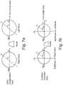
- Figure 7a illustrates the astigmatism axis ⁇ as defined in the TABO convention and figure 7b illustrates the cylinder axis ⁇ AX in a convention defined to characterize an aspherical surface.
- the cylinder axis ⁇ AX is the angle of the orientation of the maximum curvature CURV max with relation to a reference axis and in the chosen sense of rotation.
- the reference axis is horizontal (the angle of this reference axis is 0°) and the sense of rotation is counterclockwise for each eye, when looking at the wearer (0° ⁇ AX ⁇ 180°).
- An axis value for the cylinder axis ⁇ AX of +45° therefore represents an axis oriented obliquely, which when looking at the wearer, extends from the quadrant located up on the right to the quadrant located down on the left.
- a lens element 10 comprises an object side surface F1 formed as a convex curved surface toward an object side, and an eye side surface F2 formed as a concave surface having a different curvature than the curvature of the object side surface F1.
- At least part, for example all, of the optical elements are located on the front surface of the lens element.
- At least part, for example all, of the optical elements may be located on the back surface of the lens element.
- At least part, for example all, of the optical elements may be located between the front and back surfaces of the lens element.
- the lens element may comprise zones of different refractive index forming the optical elements.
- the optical elements are micro-lenses having a contour shape being inscribable in a circle having a diameter greater than or equal to 0.8 mm and smaller than or equal to 3.0 mm.
- the optical elements may be configured so that along the at least one section of the lens the mean sphere and/or the mean cylinder of optical elements increases from the center of said section towards the peripheral part of said section.
- the optical elements are configured so that in standard wearing condition the at least one section is a horizontal section.
- the mean sphere and/or the mean cylinder may increase according to an increase function along the at least one horizontal section, the increase function being a Gaussian function.
- the Gaussian function may be different between the nasal and temporal part of the lens so as to take into account the dissymmetry of the retina of the person.
- the mean sphere and/or the mean cylinder may increase according to an increase function along the at least one horizontal section, the increase function being a Quadratic function.
- the Quadratic function may be different between the nasal and temporal part of the lens so as to take into account the dissymmetry of the retina of the person.
- the mean sphere and/or the mean cylinder of optical elements increases from a first point of said section towards the peripheral part of said section and decreases from a second point of said section towards the peripheral part of said section, the second point being closer to the peripheral part of said section than the first point.
- table 1 Such embodiment is illustrated in table 1 that provides the mean sphere of optical elements according to their radial distance to the optical center of the lens element.
- the optical elements are micro lens placed on a spherical front surface having a curvature of 329.5 mm and the lens element is made of an optical material having a refractive index of 1.591, the prescribed optical power of the wearer is of 6 D.
- the optical element is to be worn in standard wearing conditions and the retina of the wearer is considered as having a defocus of 0.8 D at an angle of 30°.
- Table 1 Distance to optical center (mm) Mean sphere of optical element (D) 0 1.992 5 2.467 7.5 2.806 10 3.024 15 2.998 20 2.485
- the mean sphere of the optical elements increases towards the peripheral part of said section and then decreases towards the peripheral part of said section.
- the refraction area comprises an optical center and optical elements are configured so that along any section passing through the optical center of the lens the mean sphere and the mean cylinder of the optical elements increases from the optical center towards the peripheral part of the lens.
- the optical elements may be regularly distributed along circles centered on the optical center of the refraction area.
- the optical elements on the circle of diameter 10 mm and centered on the optical center of the refraction area may be micro lenses having a mean sphere of 2.75 D.
- the optical elements on the circle of diameter 20 mm and centered on the optical center of the refraction area may be micro lenses having a mean sphere of 4.75 D.
- the optical elements on the circle of diameter 30 mm and centered on the optical center of the refraction area may be micro lenses having a mean sphere of 5.5 D.
- the optical elements on the circle of diameter 40 mm and centered on the optical center of the refraction area may be micro lenses having a mean sphere of 5.75 D.
- the mean cylinder of the different micro lenses may be adjusted based on the shape of the retina of the person.
- the refraction area comprises a far vision reference point, a near vision reference, and a meridian line joining the far and near vision reference points.
- the refraction area may comprise a progressive addition lens design adapted to the prescription of the person or adapted to slow down the progression of the abnormal refraction of the eye of the person wearing the lens element.
- the meridian line corresponds to the locus of the intersection of the main gaze direction with the surface of the lens.
- the optical elements are configured so that in standard wearing conditions along any horizontal section of the lens the mean sphere and/or the mean cylinder of the optical elements increases from the intersection of said horizontal section with the meridian line towards the peripheral part of the lens.
- the mean sphere and/or the mean cylinder increase function along the sections may be different depending on the position of said section along the meridian line.
- the mean sphere and/or the mean cylinder increase function along the sections are unsymmetrical.
- the mean sphere and/or the mean cylinder increase function are unsymmetrical along vertical and/or horizontal section in standard wearing conditions.
- At least one optical element 14 has an optical function of not focusing an image on the retina of the eye of the person when the lens element is worn in standard wearing conditions.
- such optical function of the optical element combined with a refraction area having at least one refractive power different from the refractive power of the prescription allows slowing down the progression of the abnormal refraction of the eye of the person wearing the lens element.
- the optical elements may be as represented on figure 1 , non-contiguous optical elements.
- two optical elements are non-contiguous if for all the paths linking the two optical elements one may measure at least along part of each path the refractive power based on a prescription for the eye of the person.
- the two optical elements When the two optical elements are on a spherical surface, the two optical elements are non-contiguous if there for all the paths linking the two optical elements one may measure at least along part of each path the curvature of said spherical surface.
- the optical elements have an optical function of focusing an image on a position other than the retina.
- At least 50%, for example at least 80%, for example all, of the optical elements have an optical function of focusing an image on a position other than the retina.
- At least one of the optical elements has a non-spherical optical function.
- At least 50%, for example at least 80%, for example all, of the optical elements 14 have a non-spherical optical function.
- a "non-spherical optical function" is to be understood as not having a single focus point.
- the at least one element having a non-spherical optical function is transparent.
- the lens element may comprise an ophthalmic lens bearing the refraction area and a clip-on bearing the plurality of at least three optical elements adapted to be removably attached to the ophthalmic lens when the lens element is worn.
- the person when the person is in a far distance environment, outside for example, the person may separate the clip-on from the ophthalmic lens and eventually substitute a second clip-on free of any of at least three optical elements.
- the second clip-on may comprise a solar tint.
- the person may also use the ophthalmic lens without any additional clip-on.
- the optical element may be added to the lens element independently on each surface of the lens element.
- the optical element may cover specific zones of the lens element, like at the center or any other area.
- the optical element density or the quantity of power may be adjusted depending on zones of the lens element.
- the optical element may be positioned in the periphery of the lens element, in order to increase the effect of the optical element on myopia control, so as to compensate peripheral defocus due to the peripheral shape of the retina for example.
- optical elements can be made using different technologies like direct surfacing, molding, casting or injection, embossing, filming, additive manufacturing, or photolithography etc...
- At least one, for example all, of the optical elements has a shape configured so as to create a caustic in front of the retina of the eye of the person.
- such optical element is configured so that every section plane where the light flux is concentrated if any, is located in front of the retina of the eye of the person.
- the at least one, for example all, of the optical element having a non-spherical optical function is a multifocal refractive micro-lens.
- an optical element is "multifocal refractive micro-lens" includes bifocals (with two focal powers), trifocals (with three focal powers), progressive addition lenses, with continuously varying focal power, for example aspherical progressive surface lenses.
- the at least one multifocal refractive micro-lens has a toric surface.
- a toric surface is a surface of revolution that can be created by rotating a circle or arc about an axis of revolution (eventually positioned at infinity) that does not pass through its center of curvature.
- Toric surface lenses have two different radial profiles at right angles to each other, therefore producing two different focal powers.
- Toric and spheric surface components of toric lenses produce an astigmatic light beam, as opposed to a single point focus.
- the at least one of the optical element having a non-spherical optical function, for example all, of the optical elements is a toric refractive micro-lens.
- the toric refractive microlens may be a pure cylinder, meaning that minimum meridian line power is zero, while maximum meridian line power is strictly positive, for instance less than 5 Diopters.
- At least one, for example all, of the optical element is made of a birefringent material.
- the optical element is made of a material having a refractive index that depends on the polarization and propagation direction of light.
- the birefringence may be quantified as the maximum difference between refractive indices exhibited by the material.
- At least one, for example all of the optical element has discontinuities, such as a discontinuous surface, for example Fresnel surfaces and/or having a refractive index profile with discontinuities.
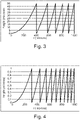
- Figure 3 represents an example of a Fresnel height profile of a optical element that may be used for the invention.
- At least one, for example all of the optical element is made of a diffractive lens.
- Figure 4 represents an example of a diffractive lens radial profile of an optical element that may be used for the invention.
- At least one, for example all, of the diffractive lenses may comprise a metasurface structure as disclosed in WO2017/176921 .
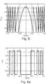
- the diffractive lens may be a Fresnel lens whose phase function ⁇ (r) has ⁇ phase jumps at the nominal wavelength, as seen in Figure 5 .
- ⁇ -Fresnel lenses for clarity's sake, as opposition to unifocal Fresnel lenses whose phase jumps are multiple values of 2 ⁇ .
- the ⁇ -Fresnel lens whose phase function is displayed in Figure 5 diffracts light mainly in two diffraction orders associated to dioptric powers 0 ⁇ and a positive one P, for example3 ⁇ .
- At least one, for example all of the optical element is a multifocal binary component.
- a binary structure displays mainly two dioptric powers, denoted -P/2 and P/2.
- the final structure represented in Figure 6c has dioptric powers 0 ⁇ and P.
- At least one, for example all of the optical element is a pixelated lens.
- An example of multifocal pixelated lens is disclosed in Eyal Ben-Eliezer et al, APPLIED OPTICS, Vol. 44, No. 14, 10 May 2005 .
- At least one, for example all of the optical element has an optical function with high order optical aberrations.
- the optical element is a micro-lens composed of continuous surfaces defined by Zernike polynomials.
Landscapes
- Health & Medical Sciences (AREA)
- Ophthalmology & Optometry (AREA)
- Physics & Mathematics (AREA)
- General Health & Medical Sciences (AREA)
- General Physics & Mathematics (AREA)
- Optics & Photonics (AREA)
- Eyeglasses (AREA)
Description
- The invention relates to a lens element intended to be worn in front of an eye of a person to suppress progression of abnormal refractions of the eye such as myopia or hyperopia.
- Myopia of an eye is characterized by the fact that the eye focuses distant objects in front of its retina. Myopia is usually corrected using a concave lens and hypermetropia is usually corrected using a convex lens.
- It has been observed that some individuals when corrected using conventional single vision optical lenses, in particular children, focus inaccurately when they observe an object which is situated at a short distance away, that is to say, in near vision conditions. Because of this focusing defect on the part of a myopic child which is corrected for his far vision, the image of an object close by is also formed behind his retina, even in the foveal area.
- Such focusing defect may have an impact on the progression of myopia of such individuals. One may observe that for most of said individual the myopia defect tends to increase over time.
- Therefore, it appears that there is a need for a lens element that would suppress or at least slow down progression of abnormal refractions of the eye such as myopia or hyperopia.
- Lenses for slowing down progression of myopia can be found for example in patent documents
US 2017/131567 ,US 2017/184875 andEP 3112925 . - To this end, the invention proposes a lens element intended to be worn in front of an eye of a person as defined in
claim 1. - Advantageously, having optical elements configured so that along at least one section of the lens the mean sphere of optical elements increases from a point of said section towards the peripheral part of said section allows increasing the defocus of the light rays in front the retina in case of myopia or behind the retina in case of hypermetropia.
- In other words, the inventors have observed that having optical elements configured so that along at least one section of the lens the mean sphere of optical elements increases from a point of said section towards the peripheral part of said section helps slow down the progression of abnormal refraction of the eye such as myopia or hyperopia.
- The solution of the invention also helps improve the aesthetics of the lens and helps compensate accommodative lag.
- According to further embodiments which can be considered alone or in combination:
- the optical elements are configured so that along at least one section of the lens the mean cylinder of optical elements increases from a point of said section towards the peripheral part of said section; and/or
- the optical elements are configured so that along the at least one section of the lens the mean sphere and/or the mean cylinder of optical elements increases from the center of said section towards the peripheral part of said section; and/or
- the refraction area comprises an optical center and optical elements are configured so that along any section passing through the optical center of the lens the mean sphere and the mean cylinder of the optical elements increases from the optical center towards the peripheral part of the lens; and/or
- the refraction area comprises a far vision reference point, a near vision reference, and a meridian line joining the far and near vision reference points, the optical elements are configured so that in standard wearing conditions along any horizontal section of the lens the mean sphere and/or the mean cylinder of the optical elements increases from the intersection of said horizontal section with the meridian line towards the peripheral part of the lens; and/or
- the mean sphere and/or the mean cylinder increase function along the sections are different depending on the position of said section along the meridian line; and/or
- the mean sphere and/or the mean cylinder increase function along the sections are unsymmetrical; and/or
- the optical elements are configured so that in standard wearing condition the at least one section is a horizontal section; and/or
- the mean sphere and/or the mean cylinder of optical elements increases from a first point of said section towards the peripheral part of said section and decreases from a second point of said section towards the peripheral part of said section, the second point being closer to the peripheral part of said section than the first point; and/or
- the mean sphere and/or the mean cylinder increase function along the at least one horizontal section is a Gaussian function; and/or
- the mean sphere and/or the mean cylinder increase function along the at least one horizontal section is a Quadratic function; and/or
- at least part, for example all, of the optical elements are located on the front surface of the ophthalmic lens; and/or
- at least part, for example all, of the optical elements are located on the back surface of the ophthalmic lens; and/or
- at least part, for example all, of the optical elements are located between the front and the back surfaces of the ophthalmic lens; and/or
- the least three optical elements are non-contiguous; and/or
- the refraction area has a first refractive power based on a prescription for correcting an abnormal refraction of said eye of the person and a second refractive power different from the first refractive power; and/or
- the difference between the first refractive power and the second refractive power is greater than or equal to 0.5D; and/or
- the refraction area is formed as the area other than the areas formed as the plurality of optical elements; and/or
- at least one, for example all of the, optical element has an optical function of not focusing an image on the retina of the eye so as to slow down the progression of the abnormal refraction of the eye; and/or
- in the refraction area the refractive power has a continuous variation; and/or
- in the refraction area the refractive power has at least one discontinuity; and/or
- the lens element is divided in five complementary zones, a central zone having a power being equal to the first refractive power and four quadrants at 45°, at least one of the quadrant having a refractive power equal to the second refractive power; and/or
- the central zone comprises a framing reference point that faces the pupil of the person gazing straight ahead in standard wearing conditions and has a diameter greater than 4mm and smaller than 20mm; and/or
- at least lower part quadrant has the second refractive power; and/or
- the refraction area has a progressive addition dioptric function; and/or
- at least one of the temporal and nasal quadrant has the second refractive power; and/or
- the four quadrants have a concentric power progression; and/or
- at least one of the optical elements is a multifocal refractive micro-lens; and/or
- the at least one multifocal refractive micro-lens comprises an aspherical surface, with or without any rotational symmetry; and/or
- at least one of the optical elements is a toric refractive micro-lens; and/or
- the at least one multifocal refractive micro-lens comprises a toric surface; and/or
- at least one of the optical elements is made of a birefringent material; and/or
- at least one of the optical elements is a diffractive lens; and/or
- the at least one diffractive lens comprises a metasurface structure; and/or
- at least one optical elements has a shape configured so as to create a caustic in front of the retina of the eye of the person; and/or
- at least one optical element is a multifocal binary component; and/or
- at least one optical element is a pixelated lens; and/or
- at least one optical element is a π-Fresnel lens; and/or
- at least part, for example all, of the optical elements are located on the front surface of the ophthalmic lens; and/or
- at least part, for example all, optical functions comprise high order optical aberrations; and/or
- the lens element comprises an ophthalmic lens bearing the refraction area and a clip-on bearing the plurality of at least three optical elements adapted to be removably attached to the ophthalmic lens when the lens element is worn.
- Non-limiting embodiments of the invention will now be described with reference to the accompanying drawing wherein:
- o
figure 1 is a plan view of a lens element according to the invention; - o
figure 2 is a general profile view of a lens element according to the invention; - o
figure 3 represents an example of a Fresnel height profile; - o
figure 4 represents an example of a diffractive lens radial profile; - o
figure 5 illustrates a π-Fresnel lens profile; - o
figures 6a to 6c illustrate a binary lens embodiment of the invention; - o
figure 7a illustrates the astigmatism axis γ of a lens in the TABO convention; and - o
figure 7b illustrates the cylinder axis γAX in a convention used to characterize an aspherical surface. - Elements in the figures are illustrated for simplicity and clarity and have not necessarily been drawn to scale. For example, the dimensions of some of the elements in the figure may be exaggerated relative to other elements to help to improve the understanding of the embodiments of the present invention.
- The invention relates to a lens element intended to be worn in front of an eye of a person.
- In the reminder of the description, terms like « up », « bottom », « horizontal », « vertical », « above », « below », « front », « rear » or other words indicating relative position may be used. These terms are to be understood in the wearing conditions of the lens element.
- In the context of the present invention, the term "lens element" can refer to an uncut optical lens or a spectacle optical lens edged to fit a specific spectacle frame or an ophthalmic lens and an optical device adapted to be positioned on the ophthalmic lens. The optical device may be positioned on the front or back surface of the ophthalmic lens. The optical device may be an optical patch. The optical device may be adapted to be removably positioned on the ophthalmic lens for example a clip configured to be clipped on a spectacle frame comprising the ophthalmic lens.
- A
lens element 10 according to the invention is adapted for a person and intended to be worn in front of an eye of said person. - As represented on
figure 1 , alens element 10 according to the invention comprises: - a
refraction area 12, and - a plurality of at least three
optical elements 14. - The
refraction area 12 has a refractive power P1 based on the prescription of the eye of the person for which the lens element is adapted. The prescription is adapted for correcting the abnormal refraction of the eye of the person. - The term "prescription" is to be understood to mean a set of optical characteristics of optical power, of astigmatism, of prismatic deviation, determined by an ophthalmologist or optometrist in order to correct the vision defects of the eye, for example by means of a lens positioned in front of his eye. For example, the prescription for a myopic eye comprises the values of optical power and of astigmatism with an axis for the distance vision.
- The refraction area is preferably formed as the area other than the areas formed as the plurality of optical elements. In other words, the refraction area is the complementary area to the areas formed by the plurality of optical elements.
- According to an embodiment of the invention, the
refraction area 12 further comprises at least a second refractive power P2 different from the refractive power P1. - In the sense of the invention, the two refractive powers are considered different when the difference between the two refractive powers is greater than or equal to 0.5 D.
- When the abnormal refraction of the eye of the person corresponds to myopia the second refractive power is greater than the refractive power P1.
- When the abnormal refraction of the eye of the person corresponds to hypermetropia, the second refractive power is smaller than the refractive power P1.
- The refraction area may have a continuous variation of refractive power. For example, the refraction area may have a progressive addition design.
- The optical design of the refraction area may comprise
- a fitting cross where the optical power is negative,
- a first zone extending in the temporal side of the refractive are when the lens element is being worn by a wearer. In the first zone, the optical power increases when moving towards the temporal side, and over the nasal side of the lens, the optical power of the ophthalmic lens is substantially the same as at the fitting cross.
- Such optical design is disclosed in greater details in
WO2016/107919 . - Alternatively, the refractive power in the refraction area may comprise at least one discontinuity.
- As represented on
figure 1 , the lens element may be divided in five complementary zones, acentral zone 16 having a power being equal to the refractive power corresponding to the prescription and four quadrants Q1, Q2, Q3, Q4 at 45°, at least one of the quadrant having at least a point where the refractive power is equal to the second refractive power. - In the sense of the invention the "quadrants at 45°" are to be understood as equal angular quadrant of 90° oriented in the directions 45°/225° and 135°/315° according to the TABO convention as illustrated on
figure 1 . - Preferably, the
central zone 16 comprises a framing reference point that faces the pupil of the person gazing straight ahead in standard wearing conditions and has a diameter greater than or equal to 4 mm and smaller than or equal to 22 mm. - The wearing conditions are to be understood as the position of the lens element with relation to the eye of a wearer, for example defined by a pantoscopic angle, a Cornea to lens distance, a Pupil-cornea distance, a center of rotation of the eye (CRE) to pupil distance, a CRE to lens distance and a wrap angle.
- The Cornea to lens distance is the distance along the visual axis of the eye in the primary position (usually taken to be the horizontal) between the cornea and the back surface of the lens; for example equal to 12mm.
- The Pupil-cornea distance is the distance along the visual axis of the eye between its pupil and cornea; usually equal to 2mm.
- The CRE to pupil distance is the distance along the visual axis of the eye between its center of rotation (CRE) and cornea; for example equal to 11.5mm.
- The CRE to lens distance is the distance along the visual axis of the eye in the primary position (usually taken to be the horizontal) between the CRE of the eye and the back surface of the lens, for example equal to 25.5mm.
- The pantoscopic angle is the angle in the vertical plane, at the intersection between the back surface of the lens and the visual axis of the eye in the primary position (usually taken to be the horizontal), between the normal to the back surface of the lens and the visual axis of the eye in the primary position; for example equal to -8°.
- The wrap angle is the angle in the horizontal plane, at the intersection between the back surface of the lens and the visual axis of the eye in the primary position (usually taken to be the horizontal), between the normal to the back surface of the lens and the visual axis of the eye in the primary position for example equal to 0°.
- An example of standard wearering condition may be defined by a pantoscopic angle of -8°, a Cornea to lens distance of 12 mm, a Pupil-cornea distance of 2 mm, a CRE to pupil distance of 11.5 mm, a CRE to lens distance of 25.5 mm and a wrap angle of 0°.
- According to an embodiment of the invention at least the lower part quadrant Q4 has a second refractive power different from the refractive power corresponding to the prescription for correcting the abnormal refraction.
- For example, the refraction area has a progressive addition dioptric function. The progressive addition dioptric function may extend between the upper part quadrant Q2 and the lower part quadrant Q4.
- Advantageously, such configuration allows compensation of accommodative lag when the person looks for example at near vision distances thanks to the addition of the lens.
- According to an embodiment, at least one of the temporal Q3 and nasal Q1 quadrant has a second refractive power different from the refractive power corresponding to the prescription of the person. For example, the temporal Q3 quadrant has a variation of power with the eccentricity of the lens.
- Advantageously, such configuration increases the efficiency of the abnormal refraction control in peripheral vision with even more effect in horizontal axis.
- According to an embodiment, the four quadrants Q1, Q2, Q3 and Q4 have a concentric power progression.
- The optical elements are configured so that at least along one section of the lens the mean sphere of the optical elements increases from a point of said section towards the peripheral of said section.
- According to an embodiment of the invention the optical elements are configured so that at least along one section of the lens, for example at least the same section as the one along which the mean sphere of the optical elements increases, the mean cylinder increases from a point of said section, for example the same point as for the mean sphere, towards the peripheral part of said section.
- As is known, a minimum curvature CURVmin is defined at any point on an aspherical surface by the formula:

- Similarly, a maximum curvature CURVmax can be defined at any point on an aspheric surface by the formula:

- It can be noticed that when the surface is locally spherical, the local minimum radius of curvature Rmin and the local maximum radius of curvature Rmax are the same and, accordingly, the minimum and maximum curvatures CURVmin and CURVmax are also identical. When the surface is aspherical, the local minimum radius of curvature Rmin and the local maximum radius of curvature Rmax are different.
- From these expressions of the minimum and maximum curvatures CURVmin and CURVmax, the minimum and maximum spheres labeled SPHmin and SPHmax can be deduced according to the kind of surface considered.
- When the surface considered is the object side surface (also referred to as the front surface), the expressions are the following:

- If the surface considered is an eyeball side surface (also referred to as the back surface), the expressions are the following:

- As is well known, a mean sphere SPHmean at any point on an aspherical surface can also be defined by the formula:

- The expression of the mean sphere therefore depends on the surface considered:
- if the surface is the object side surface,
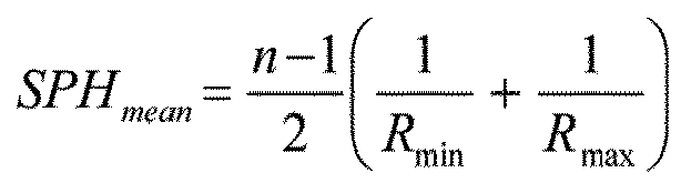
- if the surface is an eyeball side surface,

- a cylinder CYL is also defined by the formula CYL = |SPH max - SPH min|.
- The characteristics of any aspherical face of the lens may be expressed by the local mean spheres and cylinders. A surface can be considered as locally aspherical when the cylinder is at least 0.25 diopters.
- For an aspherical surface, a local cylinder axis γAX may further be defined.
Figure 7a illustrates the astigmatism axis γ as defined in the TABO convention andfigure 7b illustrates the cylinder axis γAX in a convention defined to characterize an aspherical surface. - The cylinder axis γAX is the angle of the orientation of the maximum curvature CURVmax with relation to a reference axis and in the chosen sense of rotation. In the above defined convention, the reference axis is horizontal (the angle of this reference axis is 0°) and the sense of rotation is counterclockwise for each eye, when looking at the wearer (0°≤γAX≤180°). An axis value for the cylinder axis γAX of +45° therefore represents an axis oriented obliquely, which when looking at the wearer, extends from the quadrant located up on the right to the quadrant located down on the left.
- As illustrated on
figure 2 , alens element 10 according to the invention comprises an object side surface F1 formed as a convex curved surface toward an object side, and an eye side surface F2 formed as a concave surface having a different curvature than the curvature of the object side surface F1. - According to an embodiment of the invention, at least part, for example all, of the optical elements are located on the front surface of the lens element.
- At least part, for example all, of the optical elements may be located on the back surface of the lens element.
- At least part, for example all, of the optical elements may be located between the front and back surfaces of the lens element. For example, the lens element may comprise zones of different refractive index forming the optical elements.
- According to the invention, every circular zone having a radius comprised between 2 and 4 mm comprising a geometrical center located at a distance of the optical center of the lens element greater or equal to said radius + 5mm, the ratio between the sum of areas of the parts of optical elements located inside said circular zone and the area of said circular zone is comprised between 20% and 70%.
- According to the invention the optical elements are micro-lenses having a contour shape being inscribable in a circle having a diameter greater than or equal to 0.8 mm and smaller than or equal to 3.0 mm.
- The optical elements may be configured so that along the at least one section of the lens the mean sphere and/or the mean cylinder of optical elements increases from the center of said section towards the peripheral part of said section.
- According to an embodiment of the invention, the optical elements are configured so that in standard wearing condition the at least one section is a horizontal section.
- The mean sphere and/or the mean cylinder may increase according to an increase function along the at least one horizontal section, the increase function being a Gaussian function. The Gaussian function may be different between the nasal and temporal part of the lens so as to take into account the dissymmetry of the retina of the person.
- Alternatively, the mean sphere and/or the mean cylinder may increase according to an increase function along the at least one horizontal section, the increase function being a Quadratic function. The Quadratic function may be different between the nasal and temporal part of the lens so as to take into account the dissymmetry of the retina of the person.
- According to an embodiment of the invention, the mean sphere and/or the mean cylinder of optical elements increases from a first point of said section towards the peripheral part of said section and decreases from a second point of said section towards the peripheral part of said section, the second point being closer to the peripheral part of said section than the first point.
- Such embodiment is illustrated in table 1 that provides the mean sphere of optical elements according to their radial distance to the optical center of the lens element.
- In the example of table 1, the optical elements are micro lens placed on a spherical front surface having a curvature of 329.5 mm and the lens element is made of an optical material having a refractive index of 1.591, the prescribed optical power of the wearer is of 6 D. The optical element is to be worn in standard wearing conditions and the retina of the wearer is considered as having a defocus of 0.8 D at an angle of 30°.
Table 1 Distance to optical center (mm) Mean sphere of optical element (D) 0 1.992 5 2.467 7.5 2.806 10 3.024 15 2.998 20 2.485 - As illustrated in table 1, starting close to the optical center of the lens element, the mean sphere of the optical elements increases towards the peripheral part of said section and then decreases towards the peripheral part of said section.
- According to an embodiment of the invention, the refraction area comprises an optical center and optical elements are configured so that along any section passing through the optical center of the lens the mean sphere and the mean cylinder of the optical elements increases from the optical center towards the peripheral part of the lens.
- For example, the optical elements may be regularly distributed along circles centered on the optical center of the refraction area.
- The optical elements on the circle of
diameter 10 mm and centered on the optical center of the refraction area may be micro lenses having a mean sphere of 2.75 D. - The optical elements on the circle of
diameter 20 mm and centered on the optical center of the refraction area may be micro lenses having a mean sphere of 4.75 D. - The optical elements on the circle of diameter 30 mm and centered on the optical center of the refraction area may be micro lenses having a mean sphere of 5.5 D.
- The optical elements on the circle of diameter 40 mm and centered on the optical center of the refraction area may be micro lenses having a mean sphere of 5.75 D.
- The mean cylinder of the different micro lenses may be adjusted based on the shape of the retina of the person.
- According to an embodiment of the invention, the refraction area comprises a far vision reference point, a near vision reference, and a meridian line joining the far and near vision reference points. For example, the refraction area may comprise a progressive addition lens design adapted to the prescription of the person or adapted to slow down the progression of the abnormal refraction of the eye of the person wearing the lens element.
- The meridian line corresponds to the locus of the intersection of the main gaze direction with the surface of the lens.
- Preferably, according to such embodiment, the optical elements are configured so that in standard wearing conditions along any horizontal section of the lens the mean sphere and/or the mean cylinder of the optical elements increases from the intersection of said horizontal section with the meridian line towards the peripheral part of the lens.
- The mean sphere and/or the mean cylinder increase function along the sections may be different depending on the position of said section along the meridian line.
- In particular, the mean sphere and/or the mean cylinder increase function along the sections are unsymmetrical. For example, the mean sphere and/or the mean cylinder increase function are unsymmetrical along vertical and/or horizontal section in standard wearing conditions.
- At least one
optical element 14, has an optical function of not focusing an image on the retina of the eye of the person when the lens element is worn in standard wearing conditions. - Advantageously, such optical function of the optical element combined with a refraction area having at least one refractive power different from the refractive power of the prescription allows slowing down the progression of the abnormal refraction of the eye of the person wearing the lens element.
- The optical elements may be as represented on
figure 1 , non-contiguous optical elements. - In the sense of the invention two optical elements are non-contiguous if for all the paths linking the two optical elements one may measure at least along part of each path the refractive power based on a prescription for the eye of the person.
- When the two optical elements are on a spherical surface, the two optical elements are non-contiguous if there for all the paths linking the two optical elements one may measure at least along part of each path the curvature of said spherical surface.
- According to the invention, the optical elements have an optical function of focusing an image on a position other than the retina.
- Preferably, at least 50%, for example at least 80%, for example all, of the optical elements have an optical function of focusing an image on a position other than the retina.
- According to an embodiment of the invention, at least one of the optical elements has a non-spherical optical function.
- Preferably at least 50%, for example at least 80%, for example all, of the
optical elements 14 have a non-spherical optical function. - In the sense of the invention, a "non-spherical optical function" is to be understood as not having a single focus point.
- The at least one element having a non-spherical optical function is transparent.
- According to an embodiment of the invention, the lens element may comprise an ophthalmic lens bearing the refraction area and a clip-on bearing the plurality of at least three optical elements adapted to be removably attached to the ophthalmic lens when the lens element is worn. Advantageously, when the person is in a far distance environment, outside for example, the person may separate the clip-on from the ophthalmic lens and eventually substitute a second clip-on free of any of at least three optical elements. For example, the second clip-on may comprise a solar tint. The person may also use the ophthalmic lens without any additional clip-on.
- The optical element may be added to the lens element independently on each surface of the lens element.
- One can add these optical elements on a defined array like square or hexagonal or random or other.
- The optical element may cover specific zones of the lens element, like at the center or any other area.
- The optical element density or the quantity of power may be adjusted depending on zones of the lens element. Typically, the optical element may be positioned in the periphery of the lens element, in order to increase the effect of the optical element on myopia control, so as to compensate peripheral defocus due to the peripheral shape of the retina for example.
- The optical elements can be made using different technologies like direct surfacing, molding, casting or injection, embossing, filming, additive manufacturing, or photolithography etc...
- According to an embodiment of the invention, at least one, for example all, of the optical elements has a shape configured so as to create a caustic in front of the retina of the eye of the person. In other words, such optical element is configured so that every section plane where the light flux is concentrated if any, is located in front of the retina of the eye of the person.
- According to an embodiment of the invention, the at least one, for example all, of the optical element having a non-spherical optical function is a multifocal refractive micro-lens.
- In the sense of the invention, an optical element is "multifocal refractive micro-lens" includes bifocals (with two focal powers), trifocals (with three focal powers), progressive addition lenses, with continuously varying focal power, for example aspherical progressive surface lenses.
- According to an embodiment of the invention, the at least one multifocal refractive micro-lens has a toric surface. A toric surface is a surface of revolution that can be created by rotating a circle or arc about an axis of revolution (eventually positioned at infinity) that does not pass through its center of curvature.
- Toric surface lenses have two different radial profiles at right angles to each other, therefore producing two different focal powers.
- Toric and spheric surface components of toric lenses produce an astigmatic light beam, as opposed to a single point focus.
- According to an embodiment of the invention, the at least one of the optical element having a non-spherical optical function, for example all, of the optical elements is a toric refractive micro-lens. For example, a toric refractive micro-lens with a sphere power value greater than or equal to 0 diopter (δ) and smaller than or equal to +5 diopters (δ), and cylinder power value greater than or equal to 0.25 Diopter (δ).
- As a specific embodiment, the toric refractive microlens may be a pure cylinder, meaning that minimum meridian line power is zero, while maximum meridian line power is strictly positive, for instance less than 5 Diopters.
- According to an embodiment of the invention, at least one, for example all, of the optical element, is made of a birefringent material. In other words, the optical element is made of a material having a refractive index that depends on the polarization and propagation direction of light. The birefringence may be quantified as the maximum difference between refractive indices exhibited by the material.
- According to an embodiment of the invention, at least one, for example all of the optical element, has discontinuities, such as a discontinuous surface, for example Fresnel surfaces and/or having a refractive index profile with discontinuities.
-
Figure 3 represents an example of a Fresnel height profile of a optical element that may be used for the invention. - According to an embodiment of the invention, at least one, for example all of the optical element, is made of a diffractive lens.
-
Figure 4 represents an example of a diffractive lens radial profile of an optical element that may be used for the invention. - At least one, for example all, of the diffractive lenses may comprise a metasurface structure as disclosed in
WO2017/176921 . - The diffractive lens may be a Fresnel lens whose phase function ψ(r) has π phase jumps at the nominal wavelength, as seen in
Figure 5 . One may give these structures the name "π-Fresnel lenses" for clarity's sake, as opposition to unifocal Fresnel lenses whose phase jumps are multiple values of 2π. The π-Fresnel lens whose phase function is displayed inFigure 5 diffracts light mainly in two diffraction orders associated todioptric powers 0 δ and a positive one P, for example3 δ. - According to an embodiment of the invention, at least one, for example all of the optical element, is a multifocal binary component.
- For example, a binary structure, as represented in
Figure 6a , displays mainly two dioptric powers, denoted -P/2 and P/2. When associated to a refractive structure as shown inFigure 6b , whose dioptric power is P/2, the final structure represented inFigure 6c hasdioptric powers 0 δ and P. The illustrated case is associated to P=3 δ. - According to an embodiment of the invention, at least one, for example all of the optical element, is a pixelated lens. An example of multifocal pixelated lens is disclosed in Eyal Ben-Eliezer et al, APPLIED OPTICS, Vol. 44, No. 14, 10 May 2005.
- According to an embodiment of the invention, at least one, for example all of the optical element, has an optical function with high order optical aberrations. For example, the optical element is a micro-lens composed of continuous surfaces defined by Zernike polynomials.
- The invention has been described above with the aid of embodiments without limitation of the general inventive concept.
- Many further modifications and variations will be apparent to those skilled in the art upon making reference to the foregoing illustrative embodiments, which are given by way of example only and which are not intended to limit the scope of the invention, that being determined solely by the appended claims.
- In the claims, the word "comprising" does not exclude other elements or steps, and the indefinite article "a" or "an" does not exclude a plurality. The mere fact that different features are recited in mutually different dependent claims does not indicate that a combination of these features cannot be advantageously used. Any reference signs in the claims should not be construed as limiting the scope of the invention.
Claims (13)
- A lens element (10) intended to be worn in front of an eye of a person comprising:- a refraction area (12) comprising an optical center and having a refractive power based on a prescription for said eye of the person; and- a plurality of at least three optical elements (14) having an optical function of focusing an image other than on the retina of the eye of the person when the lens element is worn in standard wearing conditions, the areas formed by said plurality of at least three optical elements (14) being complementary to the refraction area, wherein for every circular zone having a radius comprised between 4 and 8 mm comprising a geometrical center located at a distance of the optical center of the lens element (10) greater or equal to said radius + 5mm, the ratio between the sum of areas of the parts of optical elements (14) located inside said circular zone and the area of said circular zone is comprised between 20% and 70%,wherein the optical elements (14) are configured so that along any section passing through the optical center of the lens element the mean sphere of the optical elements increases from the optical center towards the peripheral part of the lens, and wherein the optical elements (14) are micro-lenses having a contour shape being inscribable in a circle having a diameter greater than or equal to 0.8 mm and smaller than or equal to 3.0 mm, and
wherein the standard wearing conditions are defined by a pantoscopic angle of -8°, a Cornea to lens distance of 12 mm, a Pupil-cornea distance of 2 mm, a CRE to pupil distance of 11.5 mm, a CRE to lens distance of 25.5 mm and a wrap angle of 0°. - The lens element according to claim 1, wherein the optical elements (14) are configured so that along at least one section of the lens element (10), the mean cylinder of optical elements increases from a point of said section towards the peripheral part of said section.
- The lens element according to claim 2, wherein the mean sphere and/or the mean cylinder of optical elements (14) increases from a first point of said section towards the peripheral part of said section and decreases from a second point of said section towards the peripheral part of said section, the second point being closer to the peripheral part of said section than the first point.
- The lens element according to any of the preceding claims, wherein the optical elements (14) are configured so that along at least one section of the lens element (10) the mean sphere and/or the mean cylinder of optical elements increases from the center of said section towards the peripheral part of said section.
- The lens element according to any of the preceding claims, wherein the optical elements are configured so that along any section passing through the optical center of the lens element (10) the mean cylinder of the optical elements (14) increases from the optical center towards the peripheral part of the lens.
- The lens element according to any of claims 1 to 4, wherein the refraction area (12) comprises a progressive addition lens design including a far vision reference point,
a near vision reference point and a meridian line joining the far and near vision reference points, the optical elements (14) are configured so that in standard wearing conditions along any horizontal section of the lens the mean sphere and/or the mean cylinder of the optical elements increases from the intersection of said horizontal section with the meridian line towards the peripheral part of the lens element (10). - The lens element according to claim 6, wherein the mean sphere and/or the mean cylinder increase function along the sections are different depending on the position of said section along the meridian line.
- The lens element according to claims 6 or 7, wherein the mean sphere and/or the mean cylinder increase function along the sections are unsymmetrical.
- The lens element according to any of the preceding claims, wherein the optical elements (14) are configured so that in standard wearing condition the at least one section is a horizontal section.
- The lens element according to claim 9, wherein the mean sphere and/or the mean cylinder increase function along the at least one horizontal section is a Gaussian function.
- The lens element according to claim 9, wherein the mean sphere and/or the mean cylinder increase function along the at least one horizontal section is a Quadratic function.
- The lens element according to any of the preceding claims, wherein the optical elements (14) are spherical micro-lenses.
- The lens element according to any of the preceding claims, wherein the least three optical elements (14) are non-contiguous.
Priority Applications (95)
| Application Number | Priority Date | Filing Date | Title |
|---|---|---|---|
| EP18305436.0A EP3553594B1 (en) | 2018-04-11 | 2018-04-11 | Lens element |
| ES18305436T ES2934252T3 (en) | 2018-04-11 | 2018-04-11 | lens element |
| DE212019000202.1U DE212019000202U1 (en) | 2018-03-01 | 2019-03-01 | Lens element |
| EP19707810.8A EP3759546B1 (en) | 2018-03-01 | 2019-03-01 | Lens element |
| PCT/EP2019/055213 WO2019166653A1 (en) | 2018-03-01 | 2019-03-01 | Lens element |
| KR1020207024529A KR20200124235A (en) | 2018-03-01 | 2019-03-01 | Lens element |
| EP24154646.4A EP4339695A2 (en) | 2018-03-01 | 2019-03-01 | Lens element |
| SG11202007813SA SG11202007813SA (en) | 2018-03-01 | 2019-03-01 | Lens element |
| CA3092607A CA3092607C (en) | 2018-03-01 | 2019-03-01 | Lens element |
| CN201980004572.8A CN111095084A (en) | 2018-03-01 | 2019-03-01 | Lens element |
| BR112020017586-2A BR112020017586B1 (en) | 2018-03-01 | 2019-03-01 | LENS ELEMENT |
| JP2020545545A JP7154306B2 (en) | 2018-03-01 | 2019-03-01 | lens element |
| PCT/EP2019/055217 WO2019166655A1 (en) | 2018-03-01 | 2019-03-01 | Lens element |
| JP2020545590A JP7418339B2 (en) | 2018-03-01 | 2019-03-01 | lens element |
| EP19707812.4A EP3759544A1 (en) | 2018-03-01 | 2019-03-01 | Lens element |
| CN202111314506.6A CN113960809A (en) | 2018-03-01 | 2019-03-01 | Lens element |
| CN201980004571.3A CN111095083B (en) | 2018-03-01 | 2019-03-01 | Lens element |
| CA3092428A CA3092428C (en) | 2018-03-01 | 2019-03-01 | Lens element for supression of abonormal refractions of the eye |
| BR112020017312-6A BR112020017312B1 (en) | 2018-03-01 | 2019-03-01 | LENS ELEMENT |
| PL19707809.0T PL3759545T3 (en) | 2018-03-01 | 2019-03-01 | Lens element |
| SG11202008023XA SG11202008023XA (en) | 2018-03-01 | 2019-03-01 | Lens element |
| CN202220219624.2U CN217085443U (en) | 2018-03-01 | 2019-03-01 | Lens element |
| HUE19707810A HUE062437T2 (en) | 2018-03-01 | 2019-03-01 | Lens element |
| EP19707811.6A EP3759547A1 (en) | 2018-03-01 | 2019-03-01 | Lens element |
| CN202220350815.2U CN217689666U (en) | 2018-03-01 | 2019-03-01 | Lens element |
| CN202111314339.5A CN113960808A (en) | 2018-03-01 | 2019-03-01 | Lens element |
| JP2020545548A JP7466450B2 (en) | 2018-03-01 | 2019-03-01 | Lens element |
| EP19708842.0A EP3759548B1 (en) | 2018-03-01 | 2019-03-01 | Lens element |
| CA3092609A CA3092609C (en) | 2018-03-01 | 2019-03-01 | Lens element |
| PCT/EP2019/055222 WO2019166659A1 (en) | 2018-03-01 | 2019-03-01 | Lens element |
| BR112020017525-0A BR112020017525B1 (en) | 2018-03-01 | 2019-03-01 | LENS ELEMENT |
| PCT/EP2019/055220 WO2019166657A1 (en) | 2018-03-01 | 2019-03-01 | Lens element |
| US16/976,662 US11567344B2 (en) | 2018-03-01 | 2019-03-01 | Lens element |
| PCT/EP2019/055216 WO2019166654A1 (en) | 2018-03-01 | 2019-03-01 | Lens element |
| JP2020545586A JP2021526230A (en) | 2018-03-01 | 2019-03-01 | Lens element |
| RU2020130029A RU2757349C1 (en) | 2018-03-01 | 2019-03-01 | Lens-shaped element |
| SG11202008011VA SG11202008011VA (en) | 2018-03-01 | 2019-03-01 | Lens element |
| SG11202008022SA SG11202008022SA (en) | 2018-03-01 | 2019-03-01 | Lens element |
| CA3092418A CA3092418A1 (en) | 2018-03-01 | 2019-03-01 | Lens element |
| CA3155413A CA3155413C (en) | 2018-03-01 | 2019-03-01 | Lens element |
| RU2020131333A RU2757820C1 (en) | 2018-03-01 | 2019-03-01 | Lens-shaped element |
| CN201980004568.1A CN111095082B (en) | 2018-03-01 | 2019-03-01 | Lens element |
| US16/976,954 US11852904B2 (en) | 2018-03-01 | 2019-03-01 | Lens element |
| DE212019000205.6U DE212019000205U1 (en) | 2018-03-01 | 2019-03-01 | Lens element |
| RU2020131393A RU2769091C2 (en) | 2018-03-01 | 2019-03-01 | Lens-shaped element |
| CN201990000358.0U CN216310444U (en) | 2018-03-01 | 2019-03-01 | Lens element |
| US16/976,654 US11899286B2 (en) | 2018-03-01 | 2019-03-01 | Lens element |
| CA3092605A CA3092605C (en) | 2018-03-01 | 2019-03-01 | Lens element |
| SG11202008010SA SG11202008010SA (en) | 2018-03-01 | 2019-03-01 | Lens element |
| KR1020207024532A KR20200124237A (en) | 2018-03-01 | 2019-03-01 | Lens element |
| DE202019005799.4U DE202019005799U1 (en) | 2018-03-01 | 2019-03-01 | lens element |
| CN202210386647.7A CN114545660B (en) | 2018-03-01 | 2019-03-01 | Lens element |
| CN202021364080.6U CN213122475U (en) | 2018-03-01 | 2019-03-01 | Spectacle optical lens, uncut optical lens, lens element |
| KR1020227011719A KR102481762B1 (en) | 2018-03-01 | 2019-03-01 | Lens element |
| EP19707809.0A EP3759545B1 (en) | 2018-03-01 | 2019-03-01 | Lens element |
| US16/976,595 US20210048689A1 (en) | 2018-03-01 | 2019-03-01 | Lens element |
| EP23162108.7A EP4220283A1 (en) | 2018-03-01 | 2019-03-01 | Lens element |
| DE202019005771.4U DE202019005771U1 (en) | 2018-03-01 | 2019-03-01 | lens element |
| CN202210386377.XA CN114660687A (en) | 2018-03-01 | 2019-03-01 | Lens element |
| EP21209355.3A EP4020065A1 (en) | 2018-03-01 | 2019-03-01 | Lens element |
| BR112020017510-2A BR112020017510B1 (en) | 2018-03-01 | 2019-03-01 | GLASSES LENS ELEMENT |
| CN202123299149.9U CN216561273U (en) | 2018-03-01 | 2019-03-01 | Lens element |
| JP2020545568A JP7155275B2 (en) | 2018-03-01 | 2019-03-01 | lens element |
| KR1020207024530A KR20200123141A (en) | 2018-03-01 | 2019-03-01 | Lens element |
| KR1020207024531A KR20200124236A (en) | 2018-03-01 | 2019-03-01 | Lens element |
| BR112020017188-3A BR112020017188B1 (en) | 2018-03-01 | 2019-03-01 | LENS ELEMENT AND METHOD FOR DETERMINING AN ADAPTED LENS ELEMENT TO SLOW DOWN THE PROGRESSION OF ABNORMAL REFRACTION OF A USER'S EYE |
| CN201910155409.3A CN110221454A (en) | 2018-03-01 | 2019-03-01 | Lens element |
| KR1020207024528A KR20200124234A (en) | 2018-03-01 | 2019-03-01 | Lens element |
| DE212019000204.8U DE212019000204U1 (en) | 2018-03-01 | 2019-03-01 | Lens element |
| RU2020131348A RU2768515C1 (en) | 2018-03-01 | 2019-03-01 | Lens-shaped element |
| RU2020131365A RU2765344C1 (en) | 2018-03-01 | 2019-03-01 | Lens-shaped element |
| DE202019005795.1U DE202019005795U1 (en) | 2018-03-01 | 2019-03-01 | lens element |
| CN202122895458.6U CN216561274U (en) | 2018-03-01 | 2019-03-01 | Lens element |
| DE202019005772.2U DE202019005772U1 (en) | 2018-03-01 | 2019-03-01 | lens element |
| CN201980005176.7A CN111226161B (en) | 2018-03-01 | 2019-03-01 | Lens element |
| CONC2020/0010242A CO2020010242A2 (en) | 2018-03-01 | 2020-08-19 | Lens element |
| CONC2020/0010439A CO2020010439A2 (en) | 2018-03-01 | 2020-08-25 | Lens element |
| CONC2020/0010432A CO2020010432A2 (en) | 2018-03-01 | 2020-08-25 | Lens element |
| CONC2020/0010799A CO2020010799A2 (en) | 2018-03-01 | 2020-08-28 | Lens element |
| CONC2020/0011713A CO2020011713A2 (en) | 2018-03-01 | 2020-09-23 | Lens element |
| US17/130,979 US10962804B1 (en) | 2018-03-01 | 2020-12-22 | Lens element |
| US17/131,855 US11079612B2 (en) | 2018-03-01 | 2020-12-23 | Lens element |
| US17/133,349 US11067832B2 (en) | 2018-03-01 | 2020-12-23 | Lens element |
| US17/134,600 US20210116722A1 (en) | 2018-03-01 | 2020-12-28 | Lens element |
| US17/134,606 US10948744B1 (en) | 2018-03-01 | 2020-12-28 | Lens element |
| US17/200,950 US11073704B2 (en) | 2018-03-01 | 2021-03-15 | Lens element |
| US17/353,545 US11385475B2 (en) | 2018-03-01 | 2021-06-21 | Lens element |
| US17/353,468 US11353721B2 (en) | 2018-03-01 | 2021-06-21 | Lens element |
| US17/535,082 US11378818B2 (en) | 2018-03-01 | 2021-11-24 | Lens element |
| US17/534,864 US11442290B2 (en) | 2018-03-01 | 2021-11-24 | Lens element |
| US17/456,454 US11385476B2 (en) | 2018-03-01 | 2021-11-24 | Lens element |
| JP2022067659A JP2022093412A (en) | 2018-03-01 | 2022-04-15 | Lens element |
| JP2022161057A JP7472225B2 (en) | 2018-03-01 | 2022-10-05 | Lens element |
| US17/985,609 US20230082062A1 (en) | 2018-03-01 | 2022-11-11 | Lens element |
| JP2023000638A JP2023033375A (en) | 2018-03-01 | 2023-01-05 | lens element |
Applications Claiming Priority (1)
| Application Number | Priority Date | Filing Date | Title |
|---|---|---|---|
| EP18305436.0A EP3553594B1 (en) | 2018-04-11 | 2018-04-11 | Lens element |
Publications (2)
| Publication Number | Publication Date |
|---|---|
| EP3553594A1 EP3553594A1 (en) | 2019-10-16 |
| EP3553594B1 true EP3553594B1 (en) | 2022-09-28 |
Family
ID=62046814
Family Applications (1)
| Application Number | Title | Priority Date | Filing Date |
|---|---|---|---|
| EP18305436.0A Active EP3553594B1 (en) | 2018-03-01 | 2018-04-11 | Lens element |
Country Status (2)
| Country | Link |
|---|---|
| EP (1) | EP3553594B1 (en) |
| ES (1) | ES2934252T3 (en) |
Families Citing this family (7)
| Publication number | Priority date | Publication date | Assignee | Title |
|---|---|---|---|---|
| CA3167325A1 (en) * | 2020-02-12 | 2021-08-19 | Ravi Chandra Bakaraju | Spectacle lenses with auxiliary optical elements |
| EP4006624B1 (en) | 2020-11-26 | 2024-04-24 | Carl Zeiss Vision International GmbH | Spectacle lens design, method of manufacturing a spectacle lens and method of providing a spectacle lens for at least retarding myopia progression |
| EP4006627B1 (en) | 2020-11-26 | 2023-07-12 | Carl Zeiss Vision International GmbH | Spectacle lens design, spectacle lens kit and method of manufacturing a spectacle lens |
| EP4006626A1 (en) | 2020-11-26 | 2022-06-01 | Carl Zeiss Vision International GmbH | Spectacle lens design, spectacle lens kit and method of manufacturing a spectacle lens |
| EP4089473A1 (en) | 2021-05-10 | 2022-11-16 | Carl Zeiss Vision International GmbH | Spectacle lens design, spectacle lens kit, method of manufacturing a spectacle lens and method of providing a spectacle lens design |
| CN114895483B (en) * | 2022-05-19 | 2024-04-16 | 苏州大学 | Superimposed peripheral discrete cis-standard astigmatic spectacle lens and design method thereof |
| EP4292798A1 (en) | 2022-06-14 | 2023-12-20 | Carl Zeiss Vision International GmbH | Method of providing refractive microstructures on a surface of a spectacle lens and spectacle lens design |
Citations (2)
| Publication number | Priority date | Publication date | Assignee | Title |
|---|---|---|---|---|
| US20140313475A1 (en) * | 2013-04-02 | 2014-10-23 | Essilor International (Compagnie Generale D'optique) | Active System of Vision and Associated Method for Improving Visual Comfort to a Wearer |
| US20150316788A1 (en) * | 2012-12-10 | 2015-11-05 | Brien Holden Vision Institute | Ophthalmic optical lens for vision correction having one or more areas of more positive power |
Family Cites Families (8)
| Publication number | Priority date | Publication date | Assignee | Title |
|---|---|---|---|---|
| CN103257458B (en) * | 2008-08-11 | 2015-02-11 | 诺瓦提斯公司 | Lens design and method for preventing or slowing progression of myopia |
| US8998408B2 (en) * | 2013-01-30 | 2015-04-07 | Johnson & Johnson Vision Care, Inc. | Asymmetric lens design and method for preventing and/or slowing myopia progression |
| SG10201400920RA (en) * | 2014-03-24 | 2015-10-29 | Menicon Singapore Pte Ltd | Apparatus and methods for controlling axial growth with an ocular lens |
| JP6758295B2 (en) | 2014-12-31 | 2020-09-23 | エシロール エンテルナショナル | Eyeglass eye lenses to be framed in eyeglass frames |
| BR122020016722B1 (en) * | 2015-04-15 | 2023-04-11 | Vision Ease, Lp | OPHTHALMIC LENS |
| US10877294B2 (en) * | 2015-06-23 | 2020-12-29 | Johnson & Johnson Vision Care, Inc. | Contact lens comprising non-coaxial lenslets for preventing and/or slowing myopia progression |
| US10268050B2 (en) * | 2015-11-06 | 2019-04-23 | Hoya Lens Thailand Ltd. | Spectacle lens |
| EP3440484A4 (en) | 2016-04-05 | 2019-11-27 | President and Fellows of Harvard College | Meta-lenses for sub-wavelength resolution imaging |
-
2018
- 2018-04-11 EP EP18305436.0A patent/EP3553594B1/en active Active
- 2018-04-11 ES ES18305436T patent/ES2934252T3/en active Active
Patent Citations (2)
| Publication number | Priority date | Publication date | Assignee | Title |
|---|---|---|---|---|
| US20150316788A1 (en) * | 2012-12-10 | 2015-11-05 | Brien Holden Vision Institute | Ophthalmic optical lens for vision correction having one or more areas of more positive power |
| US20140313475A1 (en) * | 2013-04-02 | 2014-10-23 | Essilor International (Compagnie Generale D'optique) | Active System of Vision and Associated Method for Improving Visual Comfort to a Wearer |
Also Published As
| Publication number | Publication date |
|---|---|
| ES2934252T3 (en) | 2023-02-20 |
| EP3553594A1 (en) | 2019-10-16 |
Similar Documents
| Publication | Publication Date | Title |
|---|---|---|
| EP3759546B1 (en) | Lens element | |
| US20210048690A1 (en) | Lens element | |
| EP3561578A1 (en) | Lens element | |
| EP3553594B1 (en) | Lens element | |
| US11378818B2 (en) | Lens element |
Legal Events
| Date | Code | Title | Description |
|---|---|---|---|
| STAA | Information on the status of an ep patent application or granted ep patent |
Free format text: STATUS: EXAMINATION IS IN PROGRESS |
|
| PUAI | Public reference made under article 153(3) epc to a published international application that has entered the european phase |
Free format text: ORIGINAL CODE: 0009012 |
|
| 17P | Request for examination filed |
Effective date: 20190509 |
|
| AK | Designated contracting states |
Kind code of ref document: A1 Designated state(s): AL AT BE BG CH CY CZ DE DK EE ES FI FR GB GR HR HU IE IS IT LI LT LU LV MC MK MT NL NO PL PT RO RS SE SI SK SM TR |
|
| AX | Request for extension of the european patent |
Extension state: BA ME |
|
| STAA | Information on the status of an ep patent application or granted ep patent |
Free format text: STATUS: EXAMINATION IS IN PROGRESS |
|
| STAA | Information on the status of an ep patent application or granted ep patent |
Free format text: STATUS: EXAMINATION IS IN PROGRESS |
|
| GRAP | Despatch of communication of intention to grant a patent |
Free format text: ORIGINAL CODE: EPIDOSNIGR1 |
|
| STAA | Information on the status of an ep patent application or granted ep patent |
Free format text: STATUS: GRANT OF PATENT IS INTENDED |
|
| INTG | Intention to grant announced |
Effective date: 20220426 |
|
| GRAS | Grant fee paid |
Free format text: ORIGINAL CODE: EPIDOSNIGR3 |
|
| GRAA | (expected) grant |
Free format text: ORIGINAL CODE: 0009210 |
|
| STAA | Information on the status of an ep patent application or granted ep patent |
Free format text: STATUS: THE PATENT HAS BEEN GRANTED |
|
| AK | Designated contracting states |
Kind code of ref document: B1 Designated state(s): AL AT BE BG CH CY CZ DE DK EE ES FI FR GB GR HR HU IE IS IT LI LT LU LV MC MK MT NL NO PL PT RO RS SE SI SK SM TR |
|
| REG | Reference to a national code |
Ref country code: GB Ref legal event code: FG4D |
|
| REG | Reference to a national code |
Ref country code: CH Ref legal event code: EP |
|
| REG | Reference to a national code |
Ref country code: AT Ref legal event code: REF Ref document number: 1521621 Country of ref document: AT Kind code of ref document: T Effective date: 20221015 |
|
| REG | Reference to a national code |
Ref country code: DE Ref legal event code: R096 Ref document number: 602018041076 Country of ref document: DE |
|
| REG | Reference to a national code |
Ref country code: IE Ref legal event code: FG4D |
|
| REG | Reference to a national code |
Ref country code: NL Ref legal event code: FP |
|
| REG | Reference to a national code |
Ref country code: LT Ref legal event code: MG9D |
|
| REG | Reference to a national code |
Ref country code: SE Ref legal event code: TRGR |
|
| PG25 | Lapsed in a contracting state [announced via postgrant information from national office to epo] |
Ref country code: RS Free format text: LAPSE BECAUSE OF FAILURE TO SUBMIT A TRANSLATION OF THE DESCRIPTION OR TO PAY THE FEE WITHIN THE PRESCRIBED TIME-LIMIT Effective date: 20220928 Ref country code: NO Free format text: LAPSE BECAUSE OF FAILURE TO SUBMIT A TRANSLATION OF THE DESCRIPTION OR TO PAY THE FEE WITHIN THE PRESCRIBED TIME-LIMIT Effective date: 20221228 Ref country code: LV Free format text: LAPSE BECAUSE OF FAILURE TO SUBMIT A TRANSLATION OF THE DESCRIPTION OR TO PAY THE FEE WITHIN THE PRESCRIBED TIME-LIMIT Effective date: 20220928 Ref country code: LT Free format text: LAPSE BECAUSE OF FAILURE TO SUBMIT A TRANSLATION OF THE DESCRIPTION OR TO PAY THE FEE WITHIN THE PRESCRIBED TIME-LIMIT Effective date: 20220928 Ref country code: FI Free format text: LAPSE BECAUSE OF FAILURE TO SUBMIT A TRANSLATION OF THE DESCRIPTION OR TO PAY THE FEE WITHIN THE PRESCRIBED TIME-LIMIT Effective date: 20220928 |
|
| REG | Reference to a national code |
Ref country code: AT Ref legal event code: MK05 Ref document number: 1521621 Country of ref document: AT Kind code of ref document: T Effective date: 20220928 |
|
| REG | Reference to a national code |
Ref country code: ES Ref legal event code: FG2A Ref document number: 2934252 Country of ref document: ES Kind code of ref document: T3 Effective date: 20230220 |
|
| PG25 | Lapsed in a contracting state [announced via postgrant information from national office to epo] |
Ref country code: HR Free format text: LAPSE BECAUSE OF FAILURE TO SUBMIT A TRANSLATION OF THE DESCRIPTION OR TO PAY THE FEE WITHIN THE PRESCRIBED TIME-LIMIT Effective date: 20220928 Ref country code: GR Free format text: LAPSE BECAUSE OF FAILURE TO SUBMIT A TRANSLATION OF THE DESCRIPTION OR TO PAY THE FEE WITHIN THE PRESCRIBED TIME-LIMIT Effective date: 20221229 |
|
| PG25 | Lapsed in a contracting state [announced via postgrant information from national office to epo] |
Ref country code: SM Free format text: LAPSE BECAUSE OF FAILURE TO SUBMIT A TRANSLATION OF THE DESCRIPTION OR TO PAY THE FEE WITHIN THE PRESCRIBED TIME-LIMIT Effective date: 20220928 Ref country code: RO Free format text: LAPSE BECAUSE OF FAILURE TO SUBMIT A TRANSLATION OF THE DESCRIPTION OR TO PAY THE FEE WITHIN THE PRESCRIBED TIME-LIMIT Effective date: 20220928 Ref country code: PT Free format text: LAPSE BECAUSE OF FAILURE TO SUBMIT A TRANSLATION OF THE DESCRIPTION OR TO PAY THE FEE WITHIN THE PRESCRIBED TIME-LIMIT Effective date: 20230130 Ref country code: CZ Free format text: LAPSE BECAUSE OF FAILURE TO SUBMIT A TRANSLATION OF THE DESCRIPTION OR TO PAY THE FEE WITHIN THE PRESCRIBED TIME-LIMIT Effective date: 20220928 Ref country code: AT Free format text: LAPSE BECAUSE OF FAILURE TO SUBMIT A TRANSLATION OF THE DESCRIPTION OR TO PAY THE FEE WITHIN THE PRESCRIBED TIME-LIMIT Effective date: 20220928 |
|
| PG25 | Lapsed in a contracting state [announced via postgrant information from national office to epo] |
Ref country code: SK Free format text: LAPSE BECAUSE OF FAILURE TO SUBMIT A TRANSLATION OF THE DESCRIPTION OR TO PAY THE FEE WITHIN THE PRESCRIBED TIME-LIMIT Effective date: 20220928 Ref country code: PL Free format text: LAPSE BECAUSE OF FAILURE TO SUBMIT A TRANSLATION OF THE DESCRIPTION OR TO PAY THE FEE WITHIN THE PRESCRIBED TIME-LIMIT Effective date: 20220928 Ref country code: IS Free format text: LAPSE BECAUSE OF FAILURE TO SUBMIT A TRANSLATION OF THE DESCRIPTION OR TO PAY THE FEE WITHIN THE PRESCRIBED TIME-LIMIT Effective date: 20230128 Ref country code: EE Free format text: LAPSE BECAUSE OF FAILURE TO SUBMIT A TRANSLATION OF THE DESCRIPTION OR TO PAY THE FEE WITHIN THE PRESCRIBED TIME-LIMIT Effective date: 20220928 |
|
| REG | Reference to a national code |
Ref country code: DE Ref legal event code: R097 Ref document number: 602018041076 Country of ref document: DE |
|
| PG25 | Lapsed in a contracting state [announced via postgrant information from national office to epo] |
Ref country code: AL Free format text: LAPSE BECAUSE OF FAILURE TO SUBMIT A TRANSLATION OF THE DESCRIPTION OR TO PAY THE FEE WITHIN THE PRESCRIBED TIME-LIMIT Effective date: 20220928 |
|
| P01 | Opt-out of the competence of the unified patent court (upc) registered |
Effective date: 20230525 |
|
| PG25 | Lapsed in a contracting state [announced via postgrant information from national office to epo] |
Ref country code: DK Free format text: LAPSE BECAUSE OF FAILURE TO SUBMIT A TRANSLATION OF THE DESCRIPTION OR TO PAY THE FEE WITHIN THE PRESCRIBED TIME-LIMIT Effective date: 20220928 |
|
| PGFP | Annual fee paid to national office [announced via postgrant information from national office to epo] |
Ref country code: IT Payment date: 20230419 Year of fee payment: 6 Ref country code: FR Payment date: 20230425 Year of fee payment: 6 Ref country code: ES Payment date: 20230503 Year of fee payment: 6 Ref country code: DE Payment date: 20230427 Year of fee payment: 6 |
|
| PLBE | No opposition filed within time limit |
Free format text: ORIGINAL CODE: 0009261 |
|
| STAA | Information on the status of an ep patent application or granted ep patent |
Free format text: STATUS: NO OPPOSITION FILED WITHIN TIME LIMIT |
|
| PGFP | Annual fee paid to national office [announced via postgrant information from national office to epo] |
Ref country code: SE Payment date: 20230427 Year of fee payment: 6 |
|
| 26N | No opposition filed |
Effective date: 20230629 |
|
| PGFP | Annual fee paid to national office [announced via postgrant information from national office to epo] |
Ref country code: GB Payment date: 20230427 Year of fee payment: 6 |
|
| PG25 | Lapsed in a contracting state [announced via postgrant information from national office to epo] |
Ref country code: SI Free format text: LAPSE BECAUSE OF FAILURE TO SUBMIT A TRANSLATION OF THE DESCRIPTION OR TO PAY THE FEE WITHIN THE PRESCRIBED TIME-LIMIT Effective date: 20220928 |
|
| REG | Reference to a national code |
Ref country code: CH Ref legal event code: PL |
|
| PG25 | Lapsed in a contracting state [announced via postgrant information from national office to epo] |
Ref country code: LU Free format text: LAPSE BECAUSE OF NON-PAYMENT OF DUE FEES Effective date: 20230411 |
|
| REG | Reference to a national code |
Ref country code: BE Ref legal event code: MM Effective date: 20230430 |
|
| PG25 | Lapsed in a contracting state [announced via postgrant information from national office to epo] |
Ref country code: MC Free format text: LAPSE BECAUSE OF FAILURE TO SUBMIT A TRANSLATION OF THE DESCRIPTION OR TO PAY THE FEE WITHIN THE PRESCRIBED TIME-LIMIT Effective date: 20220928 |
|
| PG25 | Lapsed in a contracting state [announced via postgrant information from national office to epo] |
Ref country code: MC Free format text: LAPSE BECAUSE OF FAILURE TO SUBMIT A TRANSLATION OF THE DESCRIPTION OR TO PAY THE FEE WITHIN THE PRESCRIBED TIME-LIMIT Effective date: 20220928 Ref country code: LI Free format text: LAPSE BECAUSE OF NON-PAYMENT OF DUE FEES Effective date: 20230430 Ref country code: CH Free format text: LAPSE BECAUSE OF NON-PAYMENT OF DUE FEES Effective date: 20230430 |
|
| REG | Reference to a national code |
Ref country code: IE Ref legal event code: MM4A |
|
| PG25 | Lapsed in a contracting state [announced via postgrant information from national office to epo] |
Ref country code: BE Free format text: LAPSE BECAUSE OF NON-PAYMENT OF DUE FEES Effective date: 20230430 |
|
| PG25 | Lapsed in a contracting state [announced via postgrant information from national office to epo] |
Ref country code: IE Free format text: LAPSE BECAUSE OF NON-PAYMENT OF DUE FEES Effective date: 20230411 |
|
| PG25 | Lapsed in a contracting state [announced via postgrant information from national office to epo] |
Ref country code: IE Free format text: LAPSE BECAUSE OF NON-PAYMENT OF DUE FEES Effective date: 20230411 |
|
| PGFP | Annual fee paid to national office [announced via postgrant information from national office to epo] |
Ref country code: NL Payment date: 20240426 Year of fee payment: 7 |