EP3964696A1 - Exhaust heater - Google Patents
Exhaust heater Download PDFInfo
- Publication number
- EP3964696A1 EP3964696A1 EP21189284.9A EP21189284A EP3964696A1 EP 3964696 A1 EP3964696 A1 EP 3964696A1 EP 21189284 A EP21189284 A EP 21189284A EP 3964696 A1 EP3964696 A1 EP 3964696A1
- Authority
- EP
- European Patent Office
- Prior art keywords
- exhaust gas
- radially
- gas heater
- heating conductor
- heating
- Prior art date
- Legal status (The legal status is an assumption and is not a legal conclusion. Google has not performed a legal analysis and makes no representation as to the accuracy of the status listed.)
- Granted
Links
- 238000010438 heat treatment Methods 0.000 claims abstract description 138
- 239000004020 conductor Substances 0.000 claims abstract description 134
- 238000005520 cutting process Methods 0.000 claims abstract description 19
- 239000007769 metal material Substances 0.000 claims abstract description 11
- 238000002485 combustion reaction Methods 0.000 claims abstract description 10
- 238000004804 winding Methods 0.000 claims description 66
- 239000012777 electrically insulating material Substances 0.000 claims description 13
- 239000000463 material Substances 0.000 claims description 12
- 229910052751 metal Inorganic materials 0.000 claims description 11
- 239000002184 metal Substances 0.000 claims description 11
- 238000000034 method Methods 0.000 claims description 5
- 230000002093 peripheral effect Effects 0.000 claims description 5
- 238000004519 manufacturing process Methods 0.000 claims description 4
- 238000003698 laser cutting Methods 0.000 claims description 3
- XLYOFNOQVPJJNP-UHFFFAOYSA-N water Substances O XLYOFNOQVPJJNP-UHFFFAOYSA-N 0.000 claims description 3
- 230000008878 coupling Effects 0.000 description 12
- 238000010168 coupling process Methods 0.000 description 12
- 238000005859 coupling reaction Methods 0.000 description 12
- 230000003993 interaction Effects 0.000 description 7
- 230000006735 deficit Effects 0.000 description 3
- 238000013021 overheating Methods 0.000 description 3
- 238000004080 punching Methods 0.000 description 2
- 238000011144 upstream manufacturing Methods 0.000 description 2
- VYZAMTAEIAYCRO-UHFFFAOYSA-N Chromium Chemical compound [Cr] VYZAMTAEIAYCRO-UHFFFAOYSA-N 0.000 description 1
- 229910000599 Cr alloy Inorganic materials 0.000 description 1
- 229910000990 Ni alloy Inorganic materials 0.000 description 1
- 230000006978 adaptation Effects 0.000 description 1
- 230000003197 catalytic effect Effects 0.000 description 1
- 238000006555 catalytic reaction Methods 0.000 description 1
- 229910010293 ceramic material Inorganic materials 0.000 description 1
- 238000006243 chemical reaction Methods 0.000 description 1
- 239000011651 chromium Substances 0.000 description 1
- 238000009826 distribution Methods 0.000 description 1
- 238000010292 electrical insulation Methods 0.000 description 1
- 239000002245 particle Substances 0.000 description 1
- 239000000126 substance Substances 0.000 description 1
- 238000003466 welding Methods 0.000 description 1
Images


Classifications
-
- F—MECHANICAL ENGINEERING; LIGHTING; HEATING; WEAPONS; BLASTING
- F01—MACHINES OR ENGINES IN GENERAL; ENGINE PLANTS IN GENERAL; STEAM ENGINES
- F01N—GAS-FLOW SILENCERS OR EXHAUST APPARATUS FOR MACHINES OR ENGINES IN GENERAL; GAS-FLOW SILENCERS OR EXHAUST APPARATUS FOR INTERNAL COMBUSTION ENGINES
- F01N3/00—Exhaust or silencing apparatus having means for purifying, rendering innocuous, or otherwise treating exhaust
- F01N3/08—Exhaust or silencing apparatus having means for purifying, rendering innocuous, or otherwise treating exhaust for rendering innocuous
- F01N3/10—Exhaust or silencing apparatus having means for purifying, rendering innocuous, or otherwise treating exhaust for rendering innocuous by thermal or catalytic conversion of noxious components of exhaust
- F01N3/18—Exhaust or silencing apparatus having means for purifying, rendering innocuous, or otherwise treating exhaust for rendering innocuous by thermal or catalytic conversion of noxious components of exhaust characterised by methods of operation; Control
- F01N3/20—Exhaust or silencing apparatus having means for purifying, rendering innocuous, or otherwise treating exhaust for rendering innocuous by thermal or catalytic conversion of noxious components of exhaust characterised by methods of operation; Control specially adapted for catalytic conversion ; Methods of operation or control of catalytic converters
- F01N3/2006—Periodically heating or cooling catalytic reactors, e.g. at cold starting or overheating
- F01N3/2013—Periodically heating or cooling catalytic reactors, e.g. at cold starting or overheating using electric or magnetic heating means
-
- F—MECHANICAL ENGINEERING; LIGHTING; HEATING; WEAPONS; BLASTING
- F01—MACHINES OR ENGINES IN GENERAL; ENGINE PLANTS IN GENERAL; STEAM ENGINES
- F01N—GAS-FLOW SILENCERS OR EXHAUST APPARATUS FOR MACHINES OR ENGINES IN GENERAL; GAS-FLOW SILENCERS OR EXHAUST APPARATUS FOR INTERNAL COMBUSTION ENGINES
- F01N3/00—Exhaust or silencing apparatus having means for purifying, rendering innocuous, or otherwise treating exhaust
- F01N3/02—Exhaust or silencing apparatus having means for purifying, rendering innocuous, or otherwise treating exhaust for cooling, or for removing solid constituents of, exhaust
- F01N3/021—Exhaust or silencing apparatus having means for purifying, rendering innocuous, or otherwise treating exhaust for cooling, or for removing solid constituents of, exhaust by means of filters
- F01N3/023—Exhaust or silencing apparatus having means for purifying, rendering innocuous, or otherwise treating exhaust for cooling, or for removing solid constituents of, exhaust by means of filters using means for regenerating the filters, e.g. by burning trapped particles
- F01N3/027—Exhaust or silencing apparatus having means for purifying, rendering innocuous, or otherwise treating exhaust for cooling, or for removing solid constituents of, exhaust by means of filters using means for regenerating the filters, e.g. by burning trapped particles using electric or magnetic heating means
-
- F—MECHANICAL ENGINEERING; LIGHTING; HEATING; WEAPONS; BLASTING
- F01—MACHINES OR ENGINES IN GENERAL; ENGINE PLANTS IN GENERAL; STEAM ENGINES
- F01N—GAS-FLOW SILENCERS OR EXHAUST APPARATUS FOR MACHINES OR ENGINES IN GENERAL; GAS-FLOW SILENCERS OR EXHAUST APPARATUS FOR INTERNAL COMBUSTION ENGINES
- F01N3/00—Exhaust or silencing apparatus having means for purifying, rendering innocuous, or otherwise treating exhaust
- F01N3/08—Exhaust or silencing apparatus having means for purifying, rendering innocuous, or otherwise treating exhaust for rendering innocuous
- F01N3/10—Exhaust or silencing apparatus having means for purifying, rendering innocuous, or otherwise treating exhaust for rendering innocuous by thermal or catalytic conversion of noxious components of exhaust
- F01N3/24—Exhaust or silencing apparatus having means for purifying, rendering innocuous, or otherwise treating exhaust for rendering innocuous by thermal or catalytic conversion of noxious components of exhaust characterised by constructional aspects of converting apparatus
- F01N3/28—Construction of catalytic reactors
-
- F—MECHANICAL ENGINEERING; LIGHTING; HEATING; WEAPONS; BLASTING
- F23—COMBUSTION APPARATUS; COMBUSTION PROCESSES
- F23J—REMOVAL OR TREATMENT OF COMBUSTION PRODUCTS OR COMBUSTION RESIDUES; FLUES
- F23J15/00—Arrangements of devices for treating smoke or fumes
- F23J15/08—Arrangements of devices for treating smoke or fumes of heaters
-
- H—ELECTRICITY
- H05—ELECTRIC TECHNIQUES NOT OTHERWISE PROVIDED FOR
- H05B—ELECTRIC HEATING; ELECTRIC LIGHT SOURCES NOT OTHERWISE PROVIDED FOR; CIRCUIT ARRANGEMENTS FOR ELECTRIC LIGHT SOURCES, IN GENERAL
- H05B3/00—Ohmic-resistance heating
- H05B3/02—Details
- H05B3/06—Heater elements structurally combined with coupling elements or holders
-
- H—ELECTRICITY
- H05—ELECTRIC TECHNIQUES NOT OTHERWISE PROVIDED FOR
- H05B—ELECTRIC HEATING; ELECTRIC LIGHT SOURCES NOT OTHERWISE PROVIDED FOR; CIRCUIT ARRANGEMENTS FOR ELECTRIC LIGHT SOURCES, IN GENERAL
- H05B3/00—Ohmic-resistance heating
- H05B3/10—Heating elements characterised by the composition or nature of the materials or by the arrangement of the conductor
-
- H—ELECTRICITY
- H05—ELECTRIC TECHNIQUES NOT OTHERWISE PROVIDED FOR
- H05B—ELECTRIC HEATING; ELECTRIC LIGHT SOURCES NOT OTHERWISE PROVIDED FOR; CIRCUIT ARRANGEMENTS FOR ELECTRIC LIGHT SOURCES, IN GENERAL
- H05B3/00—Ohmic-resistance heating
- H05B3/20—Heating elements having extended surface area substantially in a two-dimensional plane, e.g. plate-heater
- H05B3/22—Heating elements having extended surface area substantially in a two-dimensional plane, e.g. plate-heater non-flexible
- H05B3/32—Heating elements having extended surface area substantially in a two-dimensional plane, e.g. plate-heater non-flexible heating conductor mounted on insulators on a metallic frame
-
- F—MECHANICAL ENGINEERING; LIGHTING; HEATING; WEAPONS; BLASTING
- F01—MACHINES OR ENGINES IN GENERAL; ENGINE PLANTS IN GENERAL; STEAM ENGINES
- F01N—GAS-FLOW SILENCERS OR EXHAUST APPARATUS FOR MACHINES OR ENGINES IN GENERAL; GAS-FLOW SILENCERS OR EXHAUST APPARATUS FOR INTERNAL COMBUSTION ENGINES
- F01N2240/00—Combination or association of two or more different exhaust treating devices, or of at least one such device with an auxiliary device, not covered by indexing codes F01N2230/00 or F01N2250/00, one of the devices being
- F01N2240/16—Combination or association of two or more different exhaust treating devices, or of at least one such device with an auxiliary device, not covered by indexing codes F01N2230/00 or F01N2250/00, one of the devices being an electric heater, i.e. a resistance heater
-
- H—ELECTRICITY
- H05—ELECTRIC TECHNIQUES NOT OTHERWISE PROVIDED FOR
- H05B—ELECTRIC HEATING; ELECTRIC LIGHT SOURCES NOT OTHERWISE PROVIDED FOR; CIRCUIT ARRANGEMENTS FOR ELECTRIC LIGHT SOURCES, IN GENERAL
- H05B2203/00—Aspects relating to Ohmic resistive heating covered by group H05B3/00
- H05B2203/002—Heaters using a particular layout for the resistive material or resistive elements
- H05B2203/003—Heaters using a particular layout for the resistive material or resistive elements using serpentine layout
-
- H—ELECTRICITY
- H05—ELECTRIC TECHNIQUES NOT OTHERWISE PROVIDED FOR
- H05B—ELECTRIC HEATING; ELECTRIC LIGHT SOURCES NOT OTHERWISE PROVIDED FOR; CIRCUIT ARRANGEMENTS FOR ELECTRIC LIGHT SOURCES, IN GENERAL
- H05B2203/00—Aspects relating to Ohmic resistive heating covered by group H05B3/00
- H05B2203/017—Manufacturing methods or apparatus for heaters
-
- H—ELECTRICITY
- H05—ELECTRIC TECHNIQUES NOT OTHERWISE PROVIDED FOR
- H05B—ELECTRIC HEATING; ELECTRIC LIGHT SOURCES NOT OTHERWISE PROVIDED FOR; CIRCUIT ARRANGEMENTS FOR ELECTRIC LIGHT SOURCES, IN GENERAL
- H05B2203/00—Aspects relating to Ohmic resistive heating covered by group H05B3/00
- H05B2203/022—Heaters specially adapted for heating gaseous material
-
- Y—GENERAL TAGGING OF NEW TECHNOLOGICAL DEVELOPMENTS; GENERAL TAGGING OF CROSS-SECTIONAL TECHNOLOGIES SPANNING OVER SEVERAL SECTIONS OF THE IPC; TECHNICAL SUBJECTS COVERED BY FORMER USPC CROSS-REFERENCE ART COLLECTIONS [XRACs] AND DIGESTS
- Y02—TECHNOLOGIES OR APPLICATIONS FOR MITIGATION OR ADAPTATION AGAINST CLIMATE CHANGE
- Y02T—CLIMATE CHANGE MITIGATION TECHNOLOGIES RELATED TO TRANSPORTATION
- Y02T10/00—Road transport of goods or passengers
- Y02T10/10—Internal combustion engine [ICE] based vehicles
- Y02T10/12—Improving ICE efficiencies
Definitions
- the present invention relates to an exhaust gas heater for an exhaust system of an internal combustion engine.
- an exhaust gas heater in which a heating conductor with a substantially circular cross-section of the heating conductor is wound spirally and arranged in a tubular housing through which exhaust gas can flow.
- the heating conductor is heated by applying an electrical voltage to the connection ends of the heating conductor, so that heat can be transferred to the exhaust gas flowing around the heating conductor.
- An exhaust gas heater for an exhaust gas system of an internal combustion engine in which a heating conductor made of strip-like flat material is provided with a central axis surrounding a spiral-like and helically axially extended structure.
- an exhaust gas heater for an exhaust system of an internal combustion engine comprising a carrier and at least one current-carrying heating conductor carried on the carrier, the heating conductor being provided by being cut out of a flat metal material.
- the process for producing the heating conductor for such an exhaust gas heater is easy to implement, since it only requires the provision of a blank of the flat metal material and the cutting out of the heating conductor, for example by punching or cutting.
- the heating conductor can be provided with almost any course and varying heating conductor cross-section. This allows over the cross section of such an exhaust gas heater Variation of the locally provided heat and thus adaptation to a possibly uneven flow of the heating conductor, which would not be possible or only with great effort by winding a heating conductor provided from, for example, wire-like or strip-like long material.
- an angular conductor cross-sectional contour has a larger surface area than a round conductor cross-sectional contour, so that a larger surface area can be provided on the heating conductor for transferring heat to the exhaust gas flowing around it.
- the heating conductor have a holding area held on the carrier and a heating area around which exhaust gas can flow.
- the exhaust gas heater is generally accommodated in a, for example, tubular housing through which exhaust gas can flow, it is particularly advantageous if the holding area is arranged radially outside of the heating area in relation to a central axis of the exhaust gas heater.
- An axially compact design can be achieved in that the holding area and the heating area are essentially arranged in a plane that is preferably orthogonal to the central axis of the exhaust gas heater. It should be pointed out here that the exhaust gas heater obviously extends transversely to such a fictitious plane.
- a plane can be defined, for example, by an axial center plane of the heating conductor or by one of the two axial sides or end faces of the heating conductor.
- the heating conductor is produced by cutting it out of a flat metal material that is generally flat, subsequent axial expansion of the heating conductor can be used to transfer heat available surface is not increased, but only the distance between adjacent sections of the heating conductor is increased, which in turn can lead to an impairment of the thermal interaction with the heating conductor flowing around the exhaust gas. It is therefore advantageous to leave the heating conductor, which is produced for example by cutting it out of a flat metal flat material, in such a flat structure.
- the carrier comprises a carrier body that surrounds the heating conductor radially on the outside and radially overlaps on at least one axial side in the holding area, and/or that the carrier has an axial connection to the heating conductor on at least one axial side of the heating conductor supporting support assembly includes.
- the carrier body can have a first carrier body part with an axial section that overlaps the holding area radially on the outside and an axial section that extends radially inwards from the axial section and the holding area on a first axial side at least partially radially overlapping first radial section as well as a second carrier body part fixed to the first carrier body part with a second radial section radially at least partially overlapping the holding area on a second axial side.
- the first carrier body part and/or the second carrier body part be designed in the manner of a ring.
- the carrier body is advantageously made of metal material for reasons of thermal and chemical stability, it is proposed to avoid an electrical short circuit that electrically insulating material is arranged between the carrier body and the holding area.
- the heating conductor is essentially not covered with electrically insulating material in its heating area.
- the heating conductor is at least partially surrounded by the carrier in its holding area with electrically insulating material interposed, it is proposed to avoid a build-up of heat in this area that the heating conductor has a larger conductor cross-sectional area in its holding area than in its heating area . Due to the larger conductor cross-sectional area in the holding area, the heating conductor in the holding area has a lower electrical resistance per unit length than in the heating area, so that due to the greater voltage drop in the heating area, more heat is provided there than in the holding area.
- the heating conductor has a changing cross-sectional dimension in its heating area.
- the heating area can have different length sections of different cross-sectional dimensions, so that due to the varying cross-sectional dimensions there are areas of different electrical resistance and thus also different amounts of heat that can be transferred to the exhaust gas.
- This is particularly advantageous in systems in which the heat conductor cannot be subjected to a uniform flow and therefore heat cannot be removed uniformly from the heat conductor by the exhaust gas flowing around it. The emergence of overheating areas can thus be avoided.
- connection sections can be provided on the holding area for electrical contacting of the heating conductor.
- the heating conductor can be designed to extend at least in regions in a coil-like manner, at least in its heating area.
- the heating conductor comprises at least one meander-winding field with a plurality of meander-winding sections arranged radially one after the other with respect to a central axis of the exhaust gas heater and extending essentially in the circumferential direction, with at least one, preferably several meander-winding sections in a first Connect the peripheral end to a meander winding section positioned radially further inwards and connect in a second peripheral end to a meander winding section positioned radially further outward.
- a radially inner, preferably a radially innermost Meander winding section of a meander winding field adjoins a radially inner, preferably a radially innermost, meander winding section of a meander winding field that is immediately adjacent to the one meander winding field in a first circumferential direction in a radially inner connection area, or/and that a radially outer, preferably a radially outermost meander winding section of a meander winding field in a radially outer connection area to a radially outer, preferably a radially outermost meander winding section of one of the meander winding fields in a second circumferential direction immediately telbar adjacent meander winding field connects
- the holding area can provide a radially outermost meander-winding section for at least one, preferably each, meander-winding field.
- the invention also relates to a method for producing an exhaust gas heater constructed according to the invention for an exhaust system, comprising the provision of a plate-like metal flat material blank and the cutting out of the heating conductor from the metal flat material blank.
- the heating conductor can be separated from the metal flat material blank by punching or cutting, preferably laser cutting or water jet cutting.
- the invention also relates to an exhaust system for an internal combustion engine, comprising a preferably tubular exhaust gas routing component and at least one exhaust gas heater constructed in accordance with the invention, which is arranged in the exhaust gas routing component and is preferably produced using the method according to the invention.
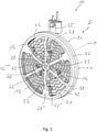
- the illustrated exhaust gas heater 10 is designed, for example, to adapt to the circular internal cross section of an exhaust gas-carrying housing that accommodates it, with a substantially circular outer peripheral contour.
- the exhaust gas heater 10 includes in its - based on a central axis M exhaust gas heater - radially outer region, a ring-like carrier 12 and a heating conductor 14 carried on the ring-like carrier 12.
- the heating conductor 14 has a holding area 16 carried on the carrier 12 radially on the outside and has a heating area 18 around which exhaust gas can flow radially inside the holding area 16 .
- the heating conductor 14 of the exhaust gas heater 10 designed according to the invention is provided by cutting out a flat metal blank made, for example, with a chromium/nickel alloy.
- the heating conductor 14 can be provided with the desired contour, for example by being punched out.
- the heating conductor 14 can be separated from the metal flat material blank by cutting, for example laser cutting or water jet cutting. Since such a metal flat material blank generally has a planar shape, the heating conductor 14 also has an essentially planar structure lying in a plane that is essentially orthogonal to the central axis M of the exhaust gas heater.
- the heating conductor 14 is designed with a winding structure. It can be clearly seen in 4 that the heating conductor 14 is provided with a total of six mutually essentially identically constructed meander winding fields 20.
- meander-winding sections 22 arranged radially adjacent to one another are arranged in such a way that, independently of local deviations, they extend essentially in the circumferential direction around the central axis M of the exhaust gas heater, the meandering Winding sections have an increasing circumferential length and thus the meander winding fields 20 have an approximately triangular circumferential contour.
- the meander winding sections 22 connect in each of their two circumferential ends 24, 26 to a meander winding section 22 positioned either radially further outwards or radially further inwards via connecting sections 28 which extend essentially radially.
- a respective radially innermost meander winding section 22 ′ of a respective meander winding field 20 is connected via an inner connection area 30 to the radially innermost meander winding section 22 ′ of another meander winding field 20 which is directly adjacent in a first circumferential direction.
- a respective outermost meander-winding section 22" is connected via an outer connection area 32 to the radially outermost meander-winding section 22' of a meander-winding field 20 that is immediately adjacent in the second circumferential direction, so that all of the meander-winding fields 20 in the heating conductor 14 that follow one another in the circumferential direction are connected to one another are connected in series.
- the radially outermost meander winding sections 22 ′ of the meander winding fields 20 essentially form the holding area 16 of the heating conductor 14 in which the latter is held on the carrier 12 .
- the carrier 12 is formed with a carrier body 34 that encompasses the heating conductor 14 in the area of the radially outermost meander winding sections 22", i.e. in the holding area 16.
- the carrier body 34 has a first carrier body part 36, which with an axial section 38 supports the holding area 16 of the
- the first carrier body part 36 also has a first radial section 40 that extends radially inward from the axial section 38. With the first radial section 40, the first carrier body part 36 almost overlaps the holding area 16 of the heating conductor 14 in the radial direction on a first axial side 42 Completely.
- the carrier body 36 also includes a second carrier body part 44, which is inserted into the first carrier body part 36 on a second axial side 46 of the heat conductor 14 and is attached to it, for example, by a material connection, such as, for. B. welding is fixed.
- the second carrier body part 44 extends radially inwards with a second radial section 48 and almost completely overlaps the holding area 16 of the heat conductor 14 in the radial direction.
- the carrier body 34 thus defines a U-shaped structure open radially inwards, in which the holding area 16 of the heating conductor 14 is accommodated with the essentially providing radially outermost meander winding sections 22 "with the interposition of electrically insulating material 50.
- the electrically insulating Material 50 covers the holding area 16 of the heating conductor 14 on the two axial sides 42, 46 and radially on the outside.
- the electrically insulating material is formed with a first ring-like insulating element 51 abutting axially on the holding area 16 on the second axial side 46 and a second ring-like insulating element 53 abutting axially on the holding area 16 on the first axial side 42 and overlapping it radially on the outside.
- the heating conductor 14 which in particular in its heating area 18 is essentially not covered by electrically insulating material, is electrically insulated with respect to the carrier 12 .
- the latter For electrical contacting of the heat conductor 14, the latter has one of these, i.e. from the holding area 16 radially inwardly beyond the carrier 12, protruding connection section 52 or 54 on two outermost meander winding sections 22', which follow one another in the circumferential direction and are not connected to one another by an outer connection area 32 on.
- a contact unit 55 that extends through a housing accommodating the exhaust gas heater 10 is connected to these in order to couple the heating conductor 14 to a voltage source.
- the carrier 12 comprises a heating conductor 14 on both axial sides 42 , 46 axially supporting support arrangement 56.
- the support arrangement 56 comprises, in association with each carrier body part 36, 44, a star-like support structure 57, 59 each having a plurality of substantially radially extending support arms 58, 61 which are radially inward in a centrally positioned coupling area 60, 63 adjoin one another and adjoin the first radial section 40 of the first carrier body part 36 and the second radial section 48 of the second carrier body part 44 radially on the outside.
- the support structures 57, 59 of the support arrangement 56 are preferably provided in one piece with the first carrier body part 36 and the second carrier body part 44, respectively, as a formed sheet metal part.
- the heating conductor 14 is in the area of the respective running there and two radially innermost meander winding sections 22 ′ of immediately adjacent meander winding fields 20 , are fixed to the support arrangement 56 .
- a fixing bolt 62 fixed to the coupling areas 60, 63 for example a fixing screw, can be used so that the radially inner connection areas 30 of the heating area 18 are clamped axially firmly between the coupling areas 60, 63.
- the heating conductor 14 can also be fixed to the support arrangement 56 using respective fixing bolts 62', 62". It can be seen that the coupling areas 60', 63' or 60", 63" provided in the circumferentially immediately adjacent support arms 58 are radially offset from one another in order to be able to alternately fix the heating conductor in different radial areas with respect to the support arrangement 56.
- the heat conductor 14 is covered locally by electrically insulating material, just like in the area of the coupling areas 60, 63, in order to prevent an electrical
- This electrically insulating material can comprise two insulating sleeves 65, 67 positioned on both sides of the heating conductor 14 and constructed, for example, with ceramic material, which isolate the heating area 18 of the heating conductor 14 with respect to the respective coupling areas 60', 63' or 60", 63” and the fixing bolts 62', 62'' passing through them electrically insulate.
- the heating conductor 14 in the heating area 18 can have a connection section 28' that is expanded in the circumferential direction in association with each of the coupling areas 60', 63' or 60", 63". an opening 29 formed therein.
- the electrical insulation of the heating conductor 14 in the various connecting sections 28' or coupling areas 60, 60', 60" or 63, 63', 63' with respect to the carrier structures 57, 59 does not rule out the possibility, within the meaning of the present invention, of the heating conductor 14 in key areas of his Heating area 18 is not covered with electrically insulating material for improved thermal interaction with this exhaust gas flowing around.
- the heating conductor 14 as a component cut out of a flat metal material makes it possible, on the one hand, to produce the heating conductor 14 with a one-piece structure in a manner that can be carried out simply and precisely.
- the in 4 shows the winding-like structure of the heating conductor 14 shown, it can be produced with almost any course, with the possibility in particular of varying the radial extent of the heating conductor in different length sections of the same with respect to one another. this is in 4 recognizable, for example, by the fact that the heating conductor 14 is designed with a greater radial extent, i.e. width, in its holding area 16, i.e.
- the heating conductor 14 - in relation to a unit of length - has a lower electrical resistance and thus when a electrical voltage is heated less than in the meander winding sections 22, 22 'with a smaller conductor cross-section area.
- This is not opposed to the fact that there may be local deviations in the conductor cross-section in the holding area 16 or in the heating area 18, in which, for example, the Heating area 18 has a larger conductor cross-section than holding area 16.
- the heating area 18 and the holding area 16 provide this relationship with their respective conductor cross-sections in the essential extension sections.
- the use of electrical energy in the areas in which the heating conductor 14 also has a significantly better thermal interaction with the exhaust gas to be heated is supported.
- the production of the heating conductor 14 by cutting it out from a flat metal material also makes it possible, for example, over the circumference provide uneven distribution of sections of the heating area 18 in order, adapted to the flow conditions present in a respective exhaust system, to achieve a different heat input into the exhaust gas flowing around the exhaust gas heater 10 distributed over the flow cross section. Locally occurring overheating or locally occurring deficits in the heating of the exhaust gas flow can thus be avoided.
- Efficient heat transfer to the exhaust gas flowing around the heating conductor 14 is also ensured by the fact that the conductor has a substantially rectangular cross-sectional contour due to the cutting out of a flat metal material. With the same conductor cross-sectional area, this has a larger surface area than a round conductor cross-sectional contour and thus ensures a larger surface area for thermal interaction with the exhaust gas to be heated.
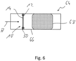
- the 6 shows a schematic representation of an exhaust system 64, in which an exhaust gas heater 10 described in detail above is integrated.
- the exhaust system 64 comprises an exhaust gas routing component 66 embodied in the manner of a tube, for example, in which the exhaust gas heater 10 is arranged upstream with respect to an exhaust gas treatment unit 68 , for example a catalytic converter or particle filter.
- the exhaust gas A flowing onto the exhaust gas treatment unit 68 first flows around the exhaust gas heater 10 positioned upstream of the exhaust gas treatment unit 68 or the heating conductor 14 thereof, is heated there and thus introduces heat into the exhaust gas treatment unit 68 .
- the exhaust gas treatment unit 68 is heated more quickly by the exhaust gas A heated at the exhaust gas heater 10 and is thus brought to the operating temperature.
- the length of time in which the reaction, for example a catalytic reaction, to be carried out in the exhaust gas treatment unit 68 cannot take place because the temperature is too low can thus be significantly shortened.
- the exhaust gas heater shown in the figures of course in various design aspects of the concrete illustrated embodiment may differ.
- This relates in particular to the course of the heat conductor, which could not necessarily be provided with a meandering structure but also, for example, with a spiral structure, and, as already mentioned, can be designed with different course structures in different circumferential areas.
- the heat conductor can have a changing cross-sectional dimension, i.e. areas with different cross-sectional dimensions, so that due to the electrical resistance that also changes with the cross-sectional dimension in the course of the heating area, the amounts of heat generated in different areas can be different and thus an inhomogeneous flow with Exhaust can be compensated to avoid overheating areas.
- the heating conductor 14 is produced by cutting it out of a substantially planar flat metal material, the axial expansion of the heating conductor 14 would not lead to an increase in the available heat transfer surface, but would only lead to a greater spacing of the adjacent sections of the heating conductor 14 and thus possibly contribute to an impairment of the thermal interaction with the exhaust gas flowing around the heat conductor 14 .
- the heat conductor 14 can also have such an axially extended structure with an axial offset between the radially outer area of the same and the radially inner area of the same.
- the support arrangement 56 that supports the heating conductor 14 axially can also have such a cone-like, axially extended structure.
Landscapes
- Engineering & Computer Science (AREA)
- Chemical & Material Sciences (AREA)
- Chemical Kinetics & Catalysis (AREA)
- Mechanical Engineering (AREA)
- General Engineering & Computer Science (AREA)
- Combustion & Propulsion (AREA)
- Health & Medical Sciences (AREA)
- Toxicology (AREA)
- Exhaust Gas After Treatment (AREA)
- Resistance Heating (AREA)
Abstract
Ein Abgasheizer für eine Abgasanlage einer Brennkraftmaschine umfasst einen Träger (12) und wenigstens einen an dem Träger (12) getragenen, stromdurchflossenen Heizleiter (14), wobei der Heizleiter (14) durch Heraustrennen aus einem Metall-Flachmaterial bereitgestellt ist.An exhaust gas heater for an exhaust system of an internal combustion engine comprises a carrier (12) and at least one current-carrying heating conductor (14) carried on the carrier (12), the heating conductor (14) being provided by cutting out a flat metal material.
Description
Die vorliegende Erfindung betrifft einen Abgasheizer für eine Abgasanlage einer Brennkraftmaschine.The present invention relates to an exhaust gas heater for an exhaust system of an internal combustion engine.
Aus der
Aus der
Es ist die Aufgabe der vorliegenden Erfindung, einen Abgasheizer für eine Abgasanlage einer Brennkraftmaschine vorzusehen, mit welchem bei einfach zu realisierendem Aufbau ein verbessertes Heizverhalten erreicht werden kann.It is the object of the present invention to provide an exhaust gas heater for an exhaust system of an internal combustion engine, with which improved heating behavior can be achieved with a structure that is easy to implement.
Erfindungsgemäß wird diese Aufgabe gelöst durch einen Abgasheizer für eine Abgasanlage einer Brennkraftmaschine, umfassend einen Träger und wenigstens einen an dem Träger getragenen, stromdurchflossenen Heizleiter, wobei der Heizleiter durch Heraustrennen aus einem Metall-Flachmaterial bereitgestellt ist.According to the invention, this object is achieved by an exhaust gas heater for an exhaust system of an internal combustion engine, comprising a carrier and at least one current-carrying heating conductor carried on the carrier, the heating conductor being provided by being cut out of a flat metal material.
Der Vorgang zum Herstellen des Heizleiters für einen derartigen Abgasheizer ist einfach zu realisieren, da dieser lediglich das Bereitstellen eines Rohlings des Metall-Flachmaterials und das Heraustrennen des Heizleiters beispielsweise durch Stanzen oder Schneiden erfordert. Gleichzeitig kann bei dieser Herstellung der Heizleiter mit nahezu beliebigen Verlauf und variierendem Heizleiter-Querschnitt bereitgestellt werden. Dies ermöglicht über den Querschnitt eines derartigen Abgasheizers eine Variation der lokal bereitgestellten Wärme und somit eine Anpassung an ein möglicherweise ungleichmäßiges Anströmen des Heizleiters, was durch Wickeln eines aus beispielsweise drahtartigem oder bandartigem Langmaterial bereitgestellten Heizleiters nicht oder nur mit sehr großem Aufwand realisierbar wäre.The process for producing the heating conductor for such an exhaust gas heater is easy to implement, since it only requires the provision of a blank of the flat metal material and the cutting out of the heating conductor, for example by punching or cutting. At the same time, with this production, the heating conductor can be provided with almost any course and varying heating conductor cross-section. This allows over the cross section of such an exhaust gas heater Variation of the locally provided heat and thus adaptation to a possibly uneven flow of the heating conductor, which would not be possible or only with great effort by winding a heating conductor provided from, for example, wire-like or strip-like long material.
Durch das Bereitstellen des Heizleiters durch Heraustrennen aus einem Metall-Flachmaterial wird es in einfacher Art und Weise möglich, den Heizleiter mit eckiger, vorzugsweise rechteckiger, Leiter-Querschnittskontur auszubilden. Eine eckige Leiter-Querschnittskontur weist bei gleicher Leiter-Querschnittsfläche eine größere Oberfläche auf, als eine runde Leiter-Querschnittskontur, so dass an dem Heizleiter eine größere Oberfläche zur Übertragung von Wärme auf diesen umströmendes Abgas bereitgestellt werden kann.By providing the heating conductor by cutting it out of a flat metal material, it becomes possible in a simple manner to form the heating conductor with an angular, preferably rectangular, conductor cross-sectional contour. With the same conductor cross-sectional area, an angular conductor cross-sectional contour has a larger surface area than a round conductor cross-sectional contour, so that a larger surface area can be provided on the heating conductor for transferring heat to the exhaust gas flowing around it.
Um an dem Heizleiter verschiedene Funktionsbereiche mit für die durch diese zu erfüllenden Funktionen optimierter Ausgestaltung bereitzustellen, wird vorgeschlagen, dass der Heizleiter einen an dem Träger gehaltenen Haltebereich und einen von Abgas umströmbaren Heizbereich aufweist.In order to provide different functional areas on the heating conductor with a configuration optimized for the functions to be fulfilled by them, it is proposed that the heating conductor have a holding area held on the carrier and a heating area around which exhaust gas can flow.
Da im Allgemeinen der Abgasheizer in einem von Abgas durchströmbaren, beispielsweise rohrartigen Gehäuse untergebracht wird, ist es besonders vorteilhaft, wenn der Haltebereich bezogen auf eine Abgasheizer-Mittenachse radial außerhalb des Heizbereichs angeordnet ist.Since the exhaust gas heater is generally accommodated in a, for example, tubular housing through which exhaust gas can flow, it is particularly advantageous if the holding area is arranged radially outside of the heating area in relation to a central axis of the exhaust gas heater.
Eine axial kompakte Bauweise kann dadurch erreicht werden, dass der Haltebereich und der Heizbereich im Wesentlichen in einer vorzugsweise zur Abgasheizer-Mittenachse orthogonalen Ebene angeordnet sind. Dabei ist darauf hinzuweisen, dass selbstverständlich der Abgasheizer quer zu einer derartigen fiktiven Ebene eine Ausdehnung aufweist. Eine derartige Ebene kann beispielsweise durch eine axiale Mittenebene des Heizleiters oder durch eine der beiden axialen Seiten bzw. Stirnflächen des Heizleiters definiert sein. Da der Heizleiter durch Heraustrennen aus einem im Allgemeinen eben ausgebildeten Metall-Flachmaterial erzeugt wird, kann durch nachträgliches axiales Ausdehnen des Heizleiters die zur Wärmeübertragung zur Verfügung stehende Oberfläche nicht vergrößert werden, sondern es wird lediglich der Abstand zwischen einander benachbarten Abschnitten des Heizleiters vergrößert, was wiederum zu einer Beeinträchtigung der thermischen Wechselwirkung mit den Heizleiter umströmendem Abgas führen kann. Daher ist es vorteilhaft, den beispielsweise durch Heraustrennen aus einem ebenen Metall-Flachmaterial erzeugten Heizleiter in einer derartigen ebenen Struktur zu belassen.An axially compact design can be achieved in that the holding area and the heating area are essentially arranged in a plane that is preferably orthogonal to the central axis of the exhaust gas heater. It should be pointed out here that the exhaust gas heater obviously extends transversely to such a fictitious plane. Such a plane can be defined, for example, by an axial center plane of the heating conductor or by one of the two axial sides or end faces of the heating conductor. Since the heating conductor is produced by cutting it out of a flat metal material that is generally flat, subsequent axial expansion of the heating conductor can be used to transfer heat available surface is not increased, but only the distance between adjacent sections of the heating conductor is increased, which in turn can lead to an impairment of the thermal interaction with the heating conductor flowing around the exhaust gas. It is therefore advantageous to leave the heating conductor, which is produced for example by cutting it out of a flat metal flat material, in such a flat structure.
Für eine stabile Anbindung des Heizleiters an den Träger wird vorgeschlagen, dass der Träger einen den Heizleiter radial außen umgebenden und im Haltebereich an wenigstens einer axialen Seite radial übergreifenden Trägerkörper umfasst, oder/und dass der Träger an wenigstens einer Axialseite des Heizleiters eine den Heizleiter axiale stützende Stützanordnung umfasst.For a stable connection of the heating conductor to the carrier, it is proposed that the carrier comprises a carrier body that surrounds the heating conductor radially on the outside and radially overlaps on at least one axial side in the holding area, and/or that the carrier has an axial connection to the heating conductor on at least one axial side of the heating conductor supporting support assembly includes.
Um den Heizleiter an den Träger anbinden zu können bzw. in den Trägerkörper integrieren zu können, kann der Trägerkörper ein erstes Trägerkörperteil mit einem den Haltebereich radial außen axial übergreifenden Axialabschnitt und einem von dem Axialabschnitt nach radial innen sich erstreckenden und den Haltebereich an einer ersten Axialseite wenigstens teilweise radial übergreifenden ersten Radialabschnitt sowie ein am ersten Trägerkörperteil festgelegtes zweites Trägerkörperteil mit einem den Haltebereich an einer zweiten Axialseite radial wenigstens teilweise übergreifenden zweiten Radialabschnitt umfassen.In order to be able to connect the heating conductor to the carrier or to be able to integrate it into the carrier body, the carrier body can have a first carrier body part with an axial section that overlaps the holding area radially on the outside and an axial section that extends radially inwards from the axial section and the holding area on a first axial side at least partially radially overlapping first radial section as well as a second carrier body part fixed to the first carrier body part with a second radial section radially at least partially overlapping the holding area on a second axial side.
Für eine über den gesamten Umfang stabile Kopplung zwischen Heizleiter und Träger wird vorgeschlagen, dass das erste Trägerkörperteil oder/und das zweite Trägerkörperteil ringartig ausgebildet ist.For a coupling between the heating conductor and the carrier that is stable over the entire circumference, it is proposed that the first carrier body part and/or the second carrier body part be designed in the manner of a ring.
Da aus Gründen der thermischen und chemischen Stabilität der Trägerkörper vorteilhafterweise mit Metallmaterial aufgebaut ist, wird zum Vermeiden eines elektrischen Kurzschlusses vorgeschlagen, dass zwischen dem Trägerkörper und dem Haltebereich elektrisch isolierendes Material angeordnet ist.Since the carrier body is advantageously made of metal material for reasons of thermal and chemical stability, it is proposed to avoid an electrical short circuit that electrically insulating material is arranged between the carrier body and the holding area.
Bei einer hinsichtlich der thermischen Wechselwirkung zwischen dem Heizbereich und dem diesen umströmenden Abgas besonders vorteilhaften Ausgestaltung kann vorgesehen sein, dass der Heizleiter in seinem Heizbereich im Wesentlichen nicht mit elektrisch isolierendem Material bedeckt ist.In an embodiment that is particularly advantageous with regard to the thermal interaction between the heating area and the exhaust gas flowing around it be provided that the heating conductor is essentially not covered with electrically insulating material in its heating area.
Insbesondere dann, wenn der Heizleiter in seinem Haltebereich von dem Träger unter Zwischenlagerung von elektrisch isolierendem Material zumindest bereichsweise umgriffen ist, wird zum Vermeiden eines Wärmestaus in diesem Bereich vorgeschlagen, dass der Heizleiter in seinem Haltebereich eine größere Leiter-Querschnittsfläche aufweist, als in seinem Heizbereich. Durch die größere Leiter-Querschnittsfläche im Haltebereich weist der Heizleiter im Haltebereich bezogen auf eine Längeneinheit einen geringeren elektrischen Widerstand auf, als im Heizbereich, so dass aufgrund des größeren Spannungsabfalls im Heizbereich dort mehr Wärme bereitgestellt wird, als im Haltebereich.In particular when the heating conductor is at least partially surrounded by the carrier in its holding area with electrically insulating material interposed, it is proposed to avoid a build-up of heat in this area that the heating conductor has a larger conductor cross-sectional area in its holding area than in its heating area . Due to the larger conductor cross-sectional area in the holding area, the heating conductor in the holding area has a lower electrical resistance per unit length than in the heating area, so that due to the greater voltage drop in the heating area, more heat is provided there than in the holding area.
Weiter kann vorgesehen sein, dass der Heizleiter in seinem Heizbereich eine sich verändernde Querschnittsabmessung aufweist. Dies bedeutet, dass der Heizbereich verschiedene Längenabschnitte verschiedener Querschnittsabmessungen aufweisen kann, so dass durch die variierende Querschnittsabmessung Bereiche unterschiedlichen elektrischen Widerstands und somit auch unterschiedlicher auf das Abgas übertragbarer Wärmemengen existieren. Dies ist insbesondere vorteilhaft in Systemen, in welchen der Heizleiter nicht gleichmäßig angeströmt werden kann und somit aus dem Heizleiter von diesen umströmendem Abgas nicht gleichmäßig Wärme abgetragen werden kann. Das Entstehen von Überhitzungsbereichen kann somit vermieden werden.Furthermore, it can be provided that the heating conductor has a changing cross-sectional dimension in its heating area. This means that the heating area can have different length sections of different cross-sectional dimensions, so that due to the varying cross-sectional dimensions there are areas of different electrical resistance and thus also different amounts of heat that can be transferred to the exhaust gas. This is particularly advantageous in systems in which the heat conductor cannot be subjected to a uniform flow and therefore heat cannot be removed uniformly from the heat conductor by the exhaust gas flowing around it. The emergence of overheating areas can thus be avoided.
Zur elektrischen Kontaktierung des Heizleiters können am Haltebereich zwei Anschlussabschnitte vorgesehen sein.Two connection sections can be provided on the holding area for electrical contacting of the heating conductor.
Für eine über den Strömungsquerschnitt großflächige thermische Wechselwirkung zwischen dem Heizleiter und dem diesen umströmenden Abgas kann der Heizleiter wenigstens in seinem Heizbereich wenigstens bereichsweise windungsartig sich erstreckend ausgebildet sein.For a large-area thermal interaction over the flow cross-section between the heating conductor and the exhaust gas flowing around it, the heating conductor can be designed to extend at least in regions in a coil-like manner, at least in its heating area.
Hierzu kann beispielsweise vorgesehen sein, dass der Heizleiter wenigstens ein Mäander-Windungsfeld mit einer Mehrzahl von bezüglich einer Abgasheizer-Mittenachse radial aufeinanderfolgend angeordneten, im Wesentlichen in Umfangsrichtung sich erstreckenden Mäander-Windungsabschnitten umfasst, wobei wenigstens ein, vorzugsweise mehrere Mäander-Windungsabschnitte in einem ersten Umfangsende an einen radial weiter innen positionierten Mäander-Windungsabschnitt anschließen und in einem zweiten Umfangsende an einen radial weiter außen positionierten Mäander-Windungsabschnitt anschließen.For this purpose, it can be provided, for example, that the heating conductor comprises at least one meander-winding field with a plurality of meander-winding sections arranged radially one after the other with respect to a central axis of the exhaust gas heater and extending essentially in the circumferential direction, with at least one, preferably several meander-winding sections in a first Connect the peripheral end to a meander winding section positioned radially further inwards and connect in a second peripheral end to a meander winding section positioned radially further outward.
Um über den Umfang verteilt eine in sich stabile Struktur des Heizleiters zu erreichen, wird vorgeschlagen, dass eine Mehrzahl von in Umfangsrichtung aufeinanderfolgenden Mäander-Windungsfeldern vorgesehen ist, und dass bei in Umfangsrichtung einander unmittelbar benachbarten Mäander-Windungsfeldern ein radial innerer, vorzugsweise ein radial innerster Mäander-Windungsabschnitt eines Mäander-Windungsfelds in einem radial inneren Anschlussbereich an einen radial inneren, vorzugsweise einen radial innersten Mäander-Windungsabschnitt eines zu dem einen Mäander-Windungsfeld in einer ersten Umfangsrichtung unmittelbar benachbarten Mäander-Windungsfelds anschließt, oder/und dass ein radial äußerer, vorzugsweise ein radial äußerster Mäander-Windungsabschnitt des einen Mäander-Windungsfelds in einem radial äußeren Anschlussbereich an einen radial äußeren, vorzugsweise einen radial äußersten Mäander-Windungsabschnitt eines zu dem einen Mäander-Windungsfeld in einer zweiten Umfangsrichtung unmittelbar benachbarten Mäander-Windungsfelds anschließt. Eine über einen sehr großen Umfangsbereich ausgedehnte Erstreckung einzelner Mäander-Windungsabschnitte kann somit vermieden werden.In order to achieve a stable structure of the heat conductor distributed over the circumference, it is proposed that a plurality of meander winding fields that follow one another in the circumferential direction be provided, and that in the case of meander winding fields that are directly adjacent to one another in the circumferential direction, a radially inner, preferably a radially innermost Meander winding section of a meander winding field adjoins a radially inner, preferably a radially innermost, meander winding section of a meander winding field that is immediately adjacent to the one meander winding field in a first circumferential direction in a radially inner connection area, or/and that a radially outer, preferably a radially outermost meander winding section of a meander winding field in a radially outer connection area to a radially outer, preferably a radially outermost meander winding section of one of the meander winding fields in a second circumferential direction immediately telbar adjacent meander winding field connects. An extension of individual meander winding sections that extends over a very large circumferential area can thus be avoided.
Der Haltebereich kann bei wenigstens einem, vorzugsweise jedem Mäander-Windungsfeld einen radial äußersten Mäander-Windungsabschnitt bereitstellen.The holding area can provide a radially outermost meander-winding section for at least one, preferably each, meander-winding field.
Die Erfindung betrifft ferner ein Verfahren zur Herstellung eines erfindungsgemäß aufgebauten Abgasheizers für eine Abgasanlage, umfassend das Bereitstellen eines plattenartigen Metall-Flachmaterial-Rohlings und das Heraustrennen des Heizleiters aus dem Metall-Flachmaterial-Rohling.The invention also relates to a method for producing an exhaust gas heater constructed according to the invention for an exhaust system, comprising the provision of a plate-like metal flat material blank and the cutting out of the heating conductor from the metal flat material blank.
Bei diesem Verfahren kann der Heizleiter durch Stanzen oder Schneiden, vorzugsweise Laserschneiden oder Wasserstrahlschneiden, aus dem Metall-Flachmaterial-Rohling herausgetrennt werden.In this method, the heating conductor can be separated from the metal flat material blank by punching or cutting, preferably laser cutting or water jet cutting.
Die Erfindung betrifft ferner Abgasanlage für eine Brennkraftmaschine, umfassend eine vorzugsweise rohrartige Abgasführungskomponente und wenigstens einen in der Abgasführungskomponente angeordneten, erfindungsgemäß aufgebauten Abgasheizer, der vorzugsweise mit dem erfindungsgemäßen Verfahren hergestellt ist.The invention also relates to an exhaust system for an internal combustion engine, comprising a preferably tubular exhaust gas routing component and at least one exhaust gas heater constructed in accordance with the invention, which is arranged in the exhaust gas routing component and is preferably produced using the method according to the invention.
Die vorliegende Erfindung wird nachfolgend mit Bezug auf die beiliegenden Figuren detailliert beschrieben. Es zeigt:
- Fig. 1
- eine perspektivische Ansicht eines Abgasheizers für eine Abgasanlage einer Brennkraftmaschine, betrachtet in Blickrichtung I in
Fig. 2 ; - Fig. 2
- eine perspektivische Ansicht des Abgasheizers der
Fig. 1 , betrachtet in Blickrichtung II inFig. 1 ; - Fig. 3
- Axialschnittansicht des Abgasheizers der
Fig. 1 und2 ; - Fig. 4
- eine Draufsicht auf einen Heizleiter des Abgasheizers der
Fig. 1-3 ; - Fig. 5
- eine Detailansicht der Verbindung des Heizleiters mit einer Stützanordnung;
- Fig. 6
- in prinzipartiger Darstellung eine einen Abgasheizer enthaltende Abgasanlage einer Brennkraftmaschine.
- 1
- a perspective view of an exhaust gas heater for an exhaust system of an internal combustion engine, viewed in direction I in
2 ; - 2
- a perspective view of the exhaust gas heater of FIG
1 , viewed in line of sight II in1 ; - 3
- Axial section view of the exhaust gas heater
1 and2 ; - 4
- a plan view of a heating conductor of the exhaust gas heater
Figures 1-3 ; - figure 5
- a detailed view of the connection of the heating conductor with a support arrangement;
- 6
- in a schematic representation of an exhaust gas heater containing exhaust system of an internal combustion engine.
Ein in den
Der Heizleiter 14 weist radial außen einen an den Träger 12 getragenen Haltebereich 16 auf und weist radial innerhalb des Haltebereichs 16 einen von Abgas umströmbaren Heizbereich 18 auf.The
Der Heizleiter 14 des erfindungsgemäß aufgebauten Abgasheizers 10 ist aus einem beispielsweise mit einer Chrom/Nickel-Legierung aufgebauten Metall-Flachmaterial-Rohling durch Heraustrennen bereitgestellt. Dabei kann der Heizleiter 14 beispielsweise durch Ausstanzen mit der gewünschten Kontur bereitgestellt werden. Alternativ kann der Heizleiter 14 durch Schneiden, beispielsweise Laserschneiden oder Wasserstrahlschneiden, aus dem Metall-Flachmaterial-Rohling herausgetrennt werden. Da im Allgemeinen ein derartiger Metall-Flachmaterial-Rohling eine ebene Gestalt aufweist, weist auch der Heizleiter 14 eine im Wesentlichen ebene, in einer zur Abgasheizer-Mittenachse M im Wesentlichen orthogonalen Ebene liegende Struktur auf.The
Der Heizleiter 14 ist in dem dargestellten Ausgestaltungsbeispiel mit einer windungsartigen Struktur ausgebildet. Deutlich zu erkennen ist in
Die radial äußersten Mäander-Windungsabschnitte 22' der Mäander-Windungsfelder 20 bilden im Wesentlichen den Haltebereich 16 des Heizleiters 14, in welchem dieser am Träger 12 gehalten ist. Hierzu ist der Träger 12 mit einem den Heizleiter 14 im Bereich der radial äußersten Mäander-Windungsabschnitte 22", also im Haltebereich 16, umgreifenden Trägerkörper 34 ausgebildet. Der Trägerkörper 34 weist ein erstes Trägerkörperteil 36 auf, welches mit einem Axialabschnitt 38 den Haltebereich 16 des Heizleiters 14 axial übergreift. Ferner weist das erste Trägerkörperteil 36 einen vom Axialabschnitt 38 sich nach radial innen erstreckenden ersten Radialabschnitt 40 auf. Mit dem ersten Radialabschnitt 40 übergreift das erste Trägerkörperteil 36 den Haltebereich 16 des Heizleiters 14 in radialer Richtung an einer ersten Axialseite 42 nahezu vollständig.The radially outermost
Der Trägerkörper 36 umfasst ferner ein zweites Trägerkörperteil 44, welches an einer zweiten Axialseite 46 des Heizleiters 14 in das erste Trägerkörperteil 36 eingesetzt ist und daran beispielsweise durch Materialschluss, wie z. B. Verschweißen, festgelegt ist. Mit einem zweiten Radialabschnitt 48 erstreckt das zweite Trägerkörperteil 44 sich nach radial innen und übergreift den Haltebereich 16 des Heizleiters 14 in radialer Richtung nahezu vollständig.The
Der Trägerkörper 34 definiert somit eine nach radial innen offene, U-förmige Struktur, in welcher der Haltebereich 16 des Heizleiters 14 mit den diesen im Wesentlichen bereitstellenden radial äußersten Mäander-Windungsabschnitten 22" unter Zwischenlagerung von elektrisch isolierendem Material 50 aufgenommen ist. Das elektrisch isolierende Material 50 überdeckt den Haltebereich 16 des Heizleiters 14 an den beiden Axialseiten 42, 46 und radial außen. Hierzu ist das elektrisch isolierendem Material mit einem axial am Haltebereich 16 an der zweiten Axialseite 46 anliegenden ersten ringartigen Isolierelement 51 und einem axial am Haltebereich 16 an der ersten Axialseite 42 anliegenden und diesen radial außenübergreifenden zweiten ringartigen Isolierelement 53 ausgebildet. Somit ist der insbesondere in seinem Heizbereich 18 im Wesentlichen nicht von elektrisch isolierendem Material überdeckte Heizleiter 14 elektrisch bezüglich des Trägers 12 isoliert.The
Zur elektrischen Kontaktierung des Heizleiters 14 weist dieser an zwei in Umfangsrichtung aufeinanderfolgenden und nicht durch einen äußeren Anschlussbereich 32 miteinander verbundenen äußersten Mäander-Windungsabschnitten 22' jeweils einen von diesen, also vom Haltebereich 16 nach radial innen über den Träger 12 hervorstehenden Anschlussabschnitt 52 bzw. 54 auf. Mit diesen ist eine ein den Abgasheizer 10 aufnehmendes Gehäuse durchgreifende Kontakteinheit 55 verbunden, um den Heizleiter 14 mit einer Spannungsquelle zu koppeln.For electrical contacting of the
Um den Heizleiter 14 am Träger 12 nicht nur in seinem radial äußeren Bereich stabil halten zu können, sondern auch über die gesamte radiale Erstreckung für eine stabile und definierte Positionierung des Heizleiters 14 zu sorgen, umfasst der Träger 12 eine den Heizleiter 14 an beiden Axialseiten 42, 46 axial stützende Stützanordnung 56. Die Stützanordnung 56 umfasst in Zuordnung zu jedem Trägerkörperteil 36, 44 eine sternartige Stützstruktur 57, 59 jeweils mit einer Mehrzahl von im Wesentlichen radial sich erstreckenden Stützarmen 58, 61, welche radial innen in einem zentral positionierten Kopplungsbereich 60, 63 aneinander anschließen und radial außen an den ersten Radialabschnitt 40 des ersten Trägerkörperteils 36 bzw. den zweiten Radialabschnitt 48 des zweiten Trägerkörperteils 44 anschließen. Die Stützstrukturen 57, 59 der Stützanordnung 56 sind vorzugsweise mit dem ersten Trägerkörperteil 36 bzw. dem zweiten Trägerkörperteil 44 jeweils als Blechumformteil einstückig bereitgestellt.In order to be able to hold the
In den radial zentralen, plattenartigen Kopplungsbereichen 60, 63 der Stützanordnung 56 ist der Heizleiter 14 im Bereich der dort jeweils verlaufenden und zwei radial innerste Mäander-Windungsabschnitte 22' einander unmittelbar benachbarter Mäander-Windungsfelder 20 verbindenden inneren Anschlussbereiche 30 an der Stützanordnung 56 fixiert. Hierzu kann beispielsweise ein an den Kopplungsbereichen 60, 63 festgelegter Fixierbolzen 62, beispielsweise Fixierschraube, genutzt werden, so dass die radial inneren Anschlussbereiche 30 des Heizbereich 18 zwischen den Kopplungsbereichen 60, 63 axial fest eingespannt sind.In the radially central, plate-
Auch in radial weiter außen liegenden Kopplungsbereichen 60', 63' bzw. 60", 63" der Stützarme 58, 61 der Stützstrukturen 57, 59 kann der Heizleiter 14 unter Einsatz jeweiliger Fixierbolzen 62', 62" an der Stützanordnung 56 fixiert werden. Dabei ist zu erkennen, dass in einander in Umfangsrichtung unmittelbar benachbarten Stützamen 58 vorgesehene Kopplungsbereiche 60', 63' bzw. 60", 63" zueinander radial versetzt liegen, um alternierend den Heizleiter in verschiedenen Radialbereichen bezüglich der Stützanordnung 56 fixieren zu können.In
Im Bereich der Kopplungsbereiche 60',63' bzw. 60", 63" bzw. der Fixierbolzen 62', 62" ist der Heizleiter 14 ebenso wie im Bereich der Kopplungsbereiche 60, 63 lokal von elektrisch isolierendem Material überdeckt, um das Entstehen eines elektrischen Kurzschlusses zu vermeiden. Dieses elektrisch isolierende Material kann zwei beidseits des Heizleiters 14 positionierte und beispielsweise mit Keramikmaterial aufgebaute Isolierhülsen 65, 67 umfassen, welche den Heizbereich 18 des Heizleiters 14 bezüglich der jeweiligen Kopplungsbereiche 60', 63' bzw. 60", 63" und der diese durchsetzenden Fixierbolzen 62', 62" elektrisch isoliert. Um dabei einen Eingriff der Isolierhülsen 65, 67 in den Heizbereich 18 zu ermöglichen, kann in Zuordnung zu jedem der Kopplungsbereiche 60', 63' bzw. 60", 63"der Heizleiter 14 im Heizbereich 18 einen jeweiligen in Umfangsrichtung erweiterten Verbindungsabschnitt 28' mit einer darin ausgebildeten Öffnung 29 aufweisen.In the area of the
Die elektrische Isolierung des Heizleiters 14 in den verschiedenen Verbindungsabschnitten 28' bzw. Kopplungsbereichen 60, 60', 60"bzw. 63, 63', 63' bezüglich der Trägerstrukturen 57, 59 schließt nicht aus, dass im Sinne der vorliegenden Erfindung der Heizleiter 14 in wesentlichen Bereichen seines Heizbereichs 18 zur verbesserten thermischen Wechselwirkung mit diesen umströmendem Abgas nicht mit elektrisch isolierendem Material bedeckt ist.The electrical insulation of the
Durch das Bereitstellen des Heizleiters 14 als aus einem Metall-Flachmaterial herausgetrenntes Bauteil wird es einerseits möglich, den Heizleiter 14 mit einstückiger Struktur in einfach und präzise durchführbarer Art und Weise zu erzeugen. Wie bereits die in
Die Herstellung des Heizleiters 14 durch Heraustrennen aus einem Metall-Flachmaterial ermöglicht es auch, beispielsweise eine über den Umfang ungleichmäßige Verteilung von Abschnitten des Heizbereichs 18 vorzusehen, um, angepasst an die in einer jeweiligen Abgasanlage vorhandenen Strömungsverhältnisse, über den Strömungsquerschnitt verteilt einen unterschiedlichen Wärmeeintrag in das den Abgasheizer 10 umströmende Abgas zu erreichen. Es können somit lokal auftretende Überhitzungen oder lokal auftretende Defizite in der Erwärmung des Abgasstroms vermieden werden.The production of the
Für eine effiziente Wärmeübertragung auf das den Heizleiter 14 umströmende Abgas sorgt auch, dass dieser aufgrund des Heraustrennens aus einem Metall-Flachmaterial eine im Wesentlichen rechteckige Leiter-Querschnittskontur aufweist. Diese weist bei gleicher Leiter-Querschnittsfläche eine größere Oberfläche auf, als eine runde Leiter-Querschnittskontur und gewährleistet somit eine größere Oberfläche zur thermischen Wechselwirkung mit dem zu erwärmenden Abgas.Efficient heat transfer to the exhaust gas flowing around the
Die
Es ist darauf hinzuweisen, dass der in den Figuren dargestellte Abgasheizer selbstverständlich in verschiedensten Ausgestaltungsaspekten von der konkret dargestellten Ausgestaltungsform abweichen kann. Dies betrifft insbesondere den Verlauf des Heizleiters, welcher nicht notwendigerweise mit mäanderartig sich windender Struktur, sondern beispielsweise auch einer spiralartigen Struktur bereitgestellt werden könnte, und, wie bereits erwähnt, in verschiedenen Umfangsbereichen mit voneinander abweichenden Verlaufsstrukturen ausgebildet sein kann. Der Heizleiter kann insbesondere in seinem Heizbereich eine sich verändernde Querschnittsabmessung, also Bereiche unterschiedlicher Querschnittsabmessung, aufweisen, so dass aufgrund des mit der Querschnittsabmessung sich auch verändernden elektrischen Widerstandes im Verlauf des Heizbereichs die in verschiedenen Bereichen erzeugten Wärmemengen unterschiedlich sein können und somit eine inhomogene Anströmung mit Abgas zum Vermeiden von Überhitzungsbereichen kompensiert werden kann. Auch können beispielsweise an einem Träger 12 axial aufeinanderfolgend mehrere bezüglich einander beispielsweise isoliert gehaltene oder aber auch in direktem Anlagekontakt stehende Heizleiter 14 positioniert werden. Selbstverständlich können in einer Abgasanlage in einem abgasführenden Gehäuse mehrere beispielsweise mit einem Heizleiter aufgebaute Abgasheizer positioniert sein. Dies ist insbesondere auch daher möglich, da gemäß einem besonders vorteilhaften Aspekt bei dem erfindungsgemäß aufgebauten Abgasheizer 10 der Heizleiter 14 im Wesentlichen in der der Zeichenebene der
Claims (18)
Applications Claiming Priority (1)
| Application Number | Priority Date | Filing Date | Title |
|---|---|---|---|
| DE102020123376.0A DE102020123376A1 (en) | 2020-09-08 | 2020-09-08 | exhaust gas heater |
Publications (2)
| Publication Number | Publication Date |
|---|---|
| EP3964696A1 true EP3964696A1 (en) | 2022-03-09 |
| EP3964696B1 EP3964696B1 (en) | 2024-01-31 |
Family
ID=77206933
Family Applications (1)
| Application Number | Title | Priority Date | Filing Date |
|---|---|---|---|
| EP21189284.9A Active EP3964696B1 (en) | 2020-09-08 | 2021-08-03 | Exhaust heater |
Country Status (6)
| Country | Link |
|---|---|
| US (1) | US11578632B2 (en) |
| EP (1) | EP3964696B1 (en) |
| JP (1) | JP7250867B2 (en) |
| KR (1) | KR102555735B1 (en) |
| CN (1) | CN114151171A (en) |
| DE (1) | DE102020123376A1 (en) |
Cited By (5)
| Publication number | Priority date | Publication date | Assignee | Title |
|---|---|---|---|---|
| EP4047194A1 (en) * | 2021-02-11 | 2022-08-24 | Benteler Automobiltechnik GmbH | Holder for an electric heating disc in an exhaust gas aftertreatment device |
| EP4074947A1 (en) * | 2021-04-16 | 2022-10-19 | Purem GmbH | Heating conductor for an exhaust gas heating system |
| FR3125846A1 (en) * | 2021-08-02 | 2023-02-03 | Faurecia Systemes D'echappement | Electric heater for exhaust line |
| EP4144964A1 (en) * | 2021-09-01 | 2023-03-08 | Purem GmbH | Exhaust gas system |
| EP4144965A1 (en) * | 2021-09-02 | 2023-03-08 | Purem GmbH | Exhaust heater |
Families Citing this family (8)
| Publication number | Priority date | Publication date | Assignee | Title |
|---|---|---|---|---|
| WO2018080578A1 (en) * | 2016-10-31 | 2018-05-03 | Watlow Electric Manufacturing Company | High power density insulated exhaust heating system |
| DE102021109568A1 (en) | 2021-03-15 | 2022-09-15 | Purem GmbH | exhaust heater |
| EP4060169B1 (en) * | 2021-03-15 | 2024-04-03 | Purem GmbH | Exhaust heater |
| DE102021113989A1 (en) | 2021-05-31 | 2022-12-01 | Purem GmbH | exhaust heater |
| DE102022102376A1 (en) | 2022-02-02 | 2023-08-03 | Purem GmbH | exhaust gas heater |
| DE102022111864A1 (en) | 2022-05-12 | 2023-11-16 | Purem GmbH | Heating device |
| DE102022111865A1 (en) | 2022-05-12 | 2023-11-16 | Purem GmbH | Heating device |
| DE102022111866A1 (en) | 2022-05-12 | 2023-11-16 | Purem GmbH | Heating device |
Citations (5)
| Publication number | Priority date | Publication date | Assignee | Title |
|---|---|---|---|---|
| US4723973A (en) * | 1985-09-28 | 1988-02-09 | Nippondenso Co., Ltd. | Purifying apparatus of a particulate trap-type for collecting particulates in exhaust gas from an engine |
| EP0608783A1 (en) * | 1993-01-25 | 1994-08-03 | Minnesota Mining And Manufacturing Company | Electrically regenerable diesel particulate filter cartridge and filter |
| DE102005011657A1 (en) | 2005-03-14 | 2006-09-21 | Beru Ag | Exhaust system for internal combustion system has exhaust pipe in which catalyst and soot filter is arranged whereby an electrical evaporator tube in the form of heat conductor is provided in exhaust gas flow direction |
| EP2935996B1 (en) | 2012-12-18 | 2019-03-20 | Watlow Electric Manufacturing Company | Improved exhaust gas heating apparatus and method of heating |
| US20200109652A1 (en) * | 2018-10-05 | 2020-04-09 | Faurecia Systemes D'echappement | Exhaust gas heating device, in particular for a combustion engine, comprising a grid wherein an electric current runs |
Family Cites Families (10)
| Publication number | Priority date | Publication date | Assignee | Title |
|---|---|---|---|---|
| JPS6078918U (en) | 1983-11-08 | 1985-06-01 | トヨタ自動車株式会社 | Diesel exhaust purification equipment |
| JP2753864B2 (en) * | 1989-07-28 | 1998-05-20 | 日本電熱株式会社 | Manufacturing method of sheet heating element |
| JPH06317146A (en) * | 1991-07-05 | 1994-11-15 | Usui Internatl Ind Co Ltd | Exhaust emission control device |
| US5501842A (en) * | 1994-08-30 | 1996-03-26 | Corning Incorporated | Axially assembled enclosure for electrical fluid heater and method |
| JP2001082129A (en) * | 1999-09-17 | 2001-03-27 | Hitachi Hometec Ltd | Heating element unit |
| JP4553555B2 (en) * | 2003-03-11 | 2010-09-29 | 西松建設株式会社 | Exhaust gas treatment method and exhaust gas treatment apparatus |
| JP6078918B2 (en) | 2013-06-21 | 2017-02-15 | パナソニックIpマネジメント株式会社 | Non-contact power feeding system for lighting and lighting fixture using the same |
| DE102020110869A1 (en) * | 2020-04-22 | 2021-10-28 | Purem GmbH | Exhaust heater |
| DE102020112391A1 (en) * | 2020-05-07 | 2021-11-11 | Purem GmbH | Exhaust gas heater for an exhaust system of an internal combustion engine |
| DE202020104976U1 (en) | 2020-08-28 | 2020-10-06 | Hjs Emission Technology Gmbh & Co. Kg | Electric heating unit for switching on in the exhaust system of an internal combustion engine as well as exhaust gas cleaning unit equipped with it |
-
2020
- 2020-09-08 DE DE102020123376.0A patent/DE102020123376A1/en active Pending
-
2021
- 2021-08-03 EP EP21189284.9A patent/EP3964696B1/en active Active
- 2021-09-07 CN CN202111040992.7A patent/CN114151171A/en active Pending
- 2021-09-07 JP JP2021145233A patent/JP7250867B2/en active Active
- 2021-09-08 US US17/469,332 patent/US11578632B2/en active Active
- 2021-09-08 KR KR1020210119948A patent/KR102555735B1/en active IP Right Grant
Patent Citations (5)
| Publication number | Priority date | Publication date | Assignee | Title |
|---|---|---|---|---|
| US4723973A (en) * | 1985-09-28 | 1988-02-09 | Nippondenso Co., Ltd. | Purifying apparatus of a particulate trap-type for collecting particulates in exhaust gas from an engine |
| EP0608783A1 (en) * | 1993-01-25 | 1994-08-03 | Minnesota Mining And Manufacturing Company | Electrically regenerable diesel particulate filter cartridge and filter |
| DE102005011657A1 (en) | 2005-03-14 | 2006-09-21 | Beru Ag | Exhaust system for internal combustion system has exhaust pipe in which catalyst and soot filter is arranged whereby an electrical evaporator tube in the form of heat conductor is provided in exhaust gas flow direction |
| EP2935996B1 (en) | 2012-12-18 | 2019-03-20 | Watlow Electric Manufacturing Company | Improved exhaust gas heating apparatus and method of heating |
| US20200109652A1 (en) * | 2018-10-05 | 2020-04-09 | Faurecia Systemes D'echappement | Exhaust gas heating device, in particular for a combustion engine, comprising a grid wherein an electric current runs |
Cited By (6)
| Publication number | Priority date | Publication date | Assignee | Title |
|---|---|---|---|---|
| EP4047194A1 (en) * | 2021-02-11 | 2022-08-24 | Benteler Automobiltechnik GmbH | Holder for an electric heating disc in an exhaust gas aftertreatment device |
| US11795850B2 (en) | 2021-02-11 | 2023-10-24 | Benteler Automobiltechnik Gmbh | Holder for an electric heating disk in an exhaust gas aftertreatment device |
| EP4074947A1 (en) * | 2021-04-16 | 2022-10-19 | Purem GmbH | Heating conductor for an exhaust gas heating system |
| FR3125846A1 (en) * | 2021-08-02 | 2023-02-03 | Faurecia Systemes D'echappement | Electric heater for exhaust line |
| EP4144964A1 (en) * | 2021-09-01 | 2023-03-08 | Purem GmbH | Exhaust gas system |
| EP4144965A1 (en) * | 2021-09-02 | 2023-03-08 | Purem GmbH | Exhaust heater |
Also Published As
| Publication number | Publication date |
|---|---|
| EP3964696B1 (en) | 2024-01-31 |
| KR20220033044A (en) | 2022-03-15 |
| US20220074333A1 (en) | 2022-03-10 |
| JP2022045351A (en) | 2022-03-18 |
| US11578632B2 (en) | 2023-02-14 |
| DE102020123376A1 (en) | 2022-03-10 |
| CN114151171A (en) | 2022-03-08 |
| KR102555735B1 (en) | 2023-07-14 |
| JP7250867B2 (en) | 2023-04-03 |
Similar Documents
| Publication | Publication Date | Title |
|---|---|---|
| EP3964696B1 (en) | Exhaust heater | |
| EP3825528B1 (en) | Exhaust heater | |
| EP2802752B1 (en) | Electrically heatable honeycomb structure with several sheet metal layers which are electrically connected to a connector pin | |
| EP2836687B1 (en) | Electrical connection of several sheet metal layers of an electrically heatable honeycomb structure and corresponding honeycomb structure | |
| EP0605479B1 (en) | Exhaust gas catalytic converter | |
| EP0581784B1 (en) | Electrically heatable honeycomb body | |
| EP4060169B1 (en) | Exhaust heater | |
| EP3901433B1 (en) | Exhaust heater | |
| EP3207229B1 (en) | Support structure, device for treating exhaust gas and method of its manufacturing | |
| EP4047194A1 (en) | Holder for an electric heating disc in an exhaust gas aftertreatment device | |
| EP3943720B1 (en) | Electric heating apparatus | |
| DE102019121382A1 (en) | Exhaust treatment device and vehicle | |
| EP3907383B1 (en) | Exhaust gas heater for an exhaust gas system of a combustion engine | |
| DE102021205198A1 (en) | Device for heating an exhaust gas stream | |
| DE102022111866A1 (en) | Heating device | |
| EP2348251B1 (en) | Device for heating a liquid and method for producing a heating device for heating a liquid | |
| EP4144964B1 (en) | Exhaust gas system | |
| EP3990760A1 (en) | Exhaust gas aftertreatment device | |
| DE19537131A1 (en) | Electrically heatable honeycomb body with stiffened power distribution structures | |
| EP4223991A1 (en) | Electric exhaust gas heater | |
| DE102022114107A1 (en) | Exhaust heater | |
| DE102022111865A1 (en) | Heating device | |
| EP4144965A1 (en) | Exhaust heater | |
| DE102022111864A1 (en) | Heating device | |
| EP4074947A1 (en) | Heating conductor for an exhaust gas heating system |
Legal Events
| Date | Code | Title | Description |
|---|---|---|---|
| PUAI | Public reference made under article 153(3) epc to a published international application that has entered the european phase |
Free format text: ORIGINAL CODE: 0009012 |
|
| STAA | Information on the status of an ep patent application or granted ep patent |
Free format text: STATUS: THE APPLICATION HAS BEEN PUBLISHED |
|
| AK | Designated contracting states |
Kind code of ref document: A1 Designated state(s): AL AT BE BG CH CY CZ DE DK EE ES FI FR GB GR HR HU IE IS IT LI LT LU LV MC MK MT NL NO PL PT RO RS SE SI SK SM TR |
|
| STAA | Information on the status of an ep patent application or granted ep patent |
Free format text: STATUS: REQUEST FOR EXAMINATION WAS MADE |
|
| 17P | Request for examination filed |
Effective date: 20220825 |
|
| RBV | Designated contracting states (corrected) |
Designated state(s): AL AT BE BG CH CY CZ DE DK EE ES FI FR GB GR HR HU IE IS IT LI LT LU LV MC MK MT NL NO PL PT RO RS SE SI SK SM TR |
|
| STAA | Information on the status of an ep patent application or granted ep patent |
Free format text: STATUS: EXAMINATION IS IN PROGRESS |
|
| 17Q | First examination report despatched |
Effective date: 20221215 |
|
| GRAP | Despatch of communication of intention to grant a patent |
Free format text: ORIGINAL CODE: EPIDOSNIGR1 |
|
| STAA | Information on the status of an ep patent application or granted ep patent |
Free format text: STATUS: GRANT OF PATENT IS INTENDED |
|
| INTG | Intention to grant announced |
Effective date: 20230913 |
|
| GRAS | Grant fee paid |
Free format text: ORIGINAL CODE: EPIDOSNIGR3 |
|
| GRAA | (expected) grant |
Free format text: ORIGINAL CODE: 0009210 |
|
| STAA | Information on the status of an ep patent application or granted ep patent |
Free format text: STATUS: THE PATENT HAS BEEN GRANTED |
|
| AK | Designated contracting states |
Kind code of ref document: B1 Designated state(s): AL AT BE BG CH CY CZ DE DK EE ES FI FR GB GR HR HU IE IS IT LI LT LU LV MC MK MT NL NO PL PT RO RS SE SI SK SM TR |
|
| REG | Reference to a national code |
Ref country code: GB Ref legal event code: FG4D Free format text: NOT ENGLISH Ref country code: CH Ref legal event code: EP |
|
| REG | Reference to a national code |
Ref country code: DE Ref legal event code: R096 Ref document number: 502021002550 Country of ref document: DE |
|
| REG | Reference to a national code |
Ref country code: IE Ref legal event code: FG4D Free format text: LANGUAGE OF EP DOCUMENT: GERMAN |