EP3862988B1 - Magnetic marker system - Google Patents
Magnetic marker system Download PDFInfo
- Publication number
- EP3862988B1 EP3862988B1 EP19868653.7A EP19868653A EP3862988B1 EP 3862988 B1 EP3862988 B1 EP 3862988B1 EP 19868653 A EP19868653 A EP 19868653A EP 3862988 B1 EP3862988 B1 EP 3862988B1
- Authority
- EP
- European Patent Office
- Prior art keywords
- magnetic
- markers
- vehicle
- sensor
- marker
- Prior art date
- Legal status (The legal status is an assumption and is not a legal conclusion. Google has not performed a legal analysis and makes no representation as to the accuracy of the status listed.)
- Active
Links
- 239000003550 marker Substances 0.000 title claims description 112
- 230000035945 sensitivity Effects 0.000 claims description 12
- 230000005389 magnetism Effects 0.000 claims description 9
- 239000011295 pitch Substances 0.000 description 72
- 238000010586 diagram Methods 0.000 description 15
- 230000004907 flux Effects 0.000 description 11
- 230000007423 decrease Effects 0.000 description 10
- 238000004088 simulation Methods 0.000 description 10
- 238000001514 detection method Methods 0.000 description 8
- 238000012360 testing method Methods 0.000 description 7
- 238000000034 method Methods 0.000 description 5
- 239000011347 resin Substances 0.000 description 5
- 229920005989 resin Polymers 0.000 description 5
- 230000000694 effects Effects 0.000 description 4
- 238000005259 measurement Methods 0.000 description 4
- 229910000859 α-Fe Inorganic materials 0.000 description 4
- 230000004308 accommodation Effects 0.000 description 3
- 238000005516 engineering process Methods 0.000 description 3
- 238000012545 processing Methods 0.000 description 3
- 238000005070 sampling Methods 0.000 description 3
- UQSXHKLRYXJYBZ-UHFFFAOYSA-N Iron oxide Chemical compound [Fe]=O UQSXHKLRYXJYBZ-UHFFFAOYSA-N 0.000 description 2
- 229910052779 Neodymium Inorganic materials 0.000 description 2
- 238000013459 approach Methods 0.000 description 2
- 238000004364 calculation method Methods 0.000 description 2
- 230000003247 decreasing effect Effects 0.000 description 2
- 238000002474 experimental method Methods 0.000 description 2
- 238000009434 installation Methods 0.000 description 2
- QEFYFXOXNSNQGX-UHFFFAOYSA-N neodymium atom Chemical compound [Nd] QEFYFXOXNSNQGX-UHFFFAOYSA-N 0.000 description 2
- 239000013598 vector Substances 0.000 description 2
- 229910019230 CoFeSiB Inorganic materials 0.000 description 1
- 229910045601 alloy Inorganic materials 0.000 description 1
- 239000000956 alloy Substances 0.000 description 1
- 230000003321 amplification Effects 0.000 description 1
- 238000004458 analytical method Methods 0.000 description 1
- 230000005540 biological transmission Effects 0.000 description 1
- 239000007767 bonding agent Substances 0.000 description 1
- 238000004891 communication Methods 0.000 description 1
- 238000005094 computer simulation Methods 0.000 description 1
- 230000001419 dependent effect Effects 0.000 description 1
- 230000001747 exhibiting effect Effects 0.000 description 1
- 239000003365 glass fiber Substances 0.000 description 1
- 230000001771 impaired effect Effects 0.000 description 1
- 239000000696 magnetic material Substances 0.000 description 1
- 239000006247 magnetic powder Substances 0.000 description 1
- 239000011159 matrix material Substances 0.000 description 1
- 239000000203 mixture Substances 0.000 description 1
- 238000000465 moulding Methods 0.000 description 1
- 238000003199 nucleic acid amplification method Methods 0.000 description 1
- 239000002245 particle Substances 0.000 description 1
- 230000002093 peripheral effect Effects 0.000 description 1
- 239000004033 plastic Substances 0.000 description 1
- 229920000642 polymer Polymers 0.000 description 1
- 230000001360 synchronised effect Effects 0.000 description 1
Images


Classifications
-
- E—FIXED CONSTRUCTIONS
- E01—CONSTRUCTION OF ROADS, RAILWAYS, OR BRIDGES
- E01F—ADDITIONAL WORK, SUCH AS EQUIPPING ROADS OR THE CONSTRUCTION OF PLATFORMS, HELICOPTER LANDING STAGES, SIGNS, SNOW FENCES, OR THE LIKE
- E01F11/00—Road engineering aspects of Embedding pads or other sensitive devices in paving or other road surfaces, e.g. traffic detectors, vehicle-operated pressure-sensitive actuators, devices for monitoring atmospheric or road conditions
-
- E—FIXED CONSTRUCTIONS
- E01—CONSTRUCTION OF ROADS, RAILWAYS, OR BRIDGES
- E01F—ADDITIONAL WORK, SUCH AS EQUIPPING ROADS OR THE CONSTRUCTION OF PLATFORMS, HELICOPTER LANDING STAGES, SIGNS, SNOW FENCES, OR THE LIKE
- E01F9/00—Arrangement of road signs or traffic signals; Arrangements for enforcing caution
- E01F9/30—Arrangements interacting with transmitters or receivers otherwise than by visible means, e.g. using radar reflectors or radio transmitters
-
- B—PERFORMING OPERATIONS; TRANSPORTING
- B60—VEHICLES IN GENERAL
- B60W—CONJOINT CONTROL OF VEHICLE SUB-UNITS OF DIFFERENT TYPE OR DIFFERENT FUNCTION; CONTROL SYSTEMS SPECIALLY ADAPTED FOR HYBRID VEHICLES; ROAD VEHICLE DRIVE CONTROL SYSTEMS FOR PURPOSES NOT RELATED TO THE CONTROL OF A PARTICULAR SUB-UNIT
- B60W30/00—Purposes of road vehicle drive control systems not related to the control of a particular sub-unit, e.g. of systems using conjoint control of vehicle sub-units
- B60W30/10—Path keeping
- B60W30/12—Lane keeping
-
- B—PERFORMING OPERATIONS; TRANSPORTING
- B60—VEHICLES IN GENERAL
- B60W—CONJOINT CONTROL OF VEHICLE SUB-UNITS OF DIFFERENT TYPE OR DIFFERENT FUNCTION; CONTROL SYSTEMS SPECIALLY ADAPTED FOR HYBRID VEHICLES; ROAD VEHICLE DRIVE CONTROL SYSTEMS FOR PURPOSES NOT RELATED TO THE CONTROL OF A PARTICULAR SUB-UNIT
- B60W60/00—Drive control systems specially adapted for autonomous road vehicles
- B60W60/001—Planning or execution of driving tasks
-
- E—FIXED CONSTRUCTIONS
- E01—CONSTRUCTION OF ROADS, RAILWAYS, OR BRIDGES
- E01F—ADDITIONAL WORK, SUCH AS EQUIPPING ROADS OR THE CONSTRUCTION OF PLATFORMS, HELICOPTER LANDING STAGES, SIGNS, SNOW FENCES, OR THE LIKE
- E01F9/00—Arrangement of road signs or traffic signals; Arrangements for enforcing caution
- E01F9/50—Road surface markings; Kerbs or road edgings, specially adapted for alerting road users
- E01F9/506—Road surface markings; Kerbs or road edgings, specially adapted for alerting road users characterised by the road surface marking material, e.g. comprising additives for improving friction or reflectivity; Methods of forming, installing or applying markings in, on or to road surfaces
- E01F9/512—Preformed road surface markings, e.g. of sheet material; Methods of applying preformed markings
-
- G—PHYSICS
- G05—CONTROLLING; REGULATING
- G05D—SYSTEMS FOR CONTROLLING OR REGULATING NON-ELECTRIC VARIABLES
- G05D1/00—Control of position, course, altitude or attitude of land, water, air or space vehicles, e.g. using automatic pilots
- G05D1/02—Control of position or course in two dimensions
- G05D1/021—Control of position or course in two dimensions specially adapted to land vehicles
- G05D1/0259—Control of position or course in two dimensions specially adapted to land vehicles using magnetic or electromagnetic means
- G05D1/0261—Control of position or course in two dimensions specially adapted to land vehicles using magnetic or electromagnetic means using magnetic plots
-
- G—PHYSICS
- G08—SIGNALLING
- G08G—TRAFFIC CONTROL SYSTEMS
- G08G1/00—Traffic control systems for road vehicles
- G08G1/01—Detecting movement of traffic to be counted or controlled
- G08G1/042—Detecting movement of traffic to be counted or controlled using inductive or magnetic detectors
-
- G—PHYSICS
- G08—SIGNALLING
- G08G—TRAFFIC CONTROL SYSTEMS
- G08G1/00—Traffic control systems for road vehicles
- G08G1/16—Anti-collision systems
- G08G1/167—Driving aids for lane monitoring, lane changing, e.g. blind spot detection
-
- B—PERFORMING OPERATIONS; TRANSPORTING
- B60—VEHICLES IN GENERAL
- B60W—CONJOINT CONTROL OF VEHICLE SUB-UNITS OF DIFFERENT TYPE OR DIFFERENT FUNCTION; CONTROL SYSTEMS SPECIALLY ADAPTED FOR HYBRID VEHICLES; ROAD VEHICLE DRIVE CONTROL SYSTEMS FOR PURPOSES NOT RELATED TO THE CONTROL OF A PARTICULAR SUB-UNIT
- B60W2420/00—Indexing codes relating to the type of sensors based on the principle of their operation
- B60W2420/50—Magnetic or electromagnetic sensors
-
- B—PERFORMING OPERATIONS; TRANSPORTING
- B60—VEHICLES IN GENERAL
- B60W—CONJOINT CONTROL OF VEHICLE SUB-UNITS OF DIFFERENT TYPE OR DIFFERENT FUNCTION; CONTROL SYSTEMS SPECIALLY ADAPTED FOR HYBRID VEHICLES; ROAD VEHICLE DRIVE CONTROL SYSTEMS FOR PURPOSES NOT RELATED TO THE CONTROL OF A PARTICULAR SUB-UNIT
- B60W2552/00—Input parameters relating to infrastructure
- B60W2552/53—Road markings, e.g. lane marker or crosswalk
Definitions
- the present invention relates to a magnetic marker system including magnetic markers laid on or in a road so that they can be detected on a vehicle side traveling on the road.
- Patent Literature 1 vehicular magnetic marker detection systems using magnetic markers laid on a road have been known (for example, refer to Patent Literature 1) .
- These magnetic marker detection systems have an object of providing various driving assists, such as automatic steering control or lane departure warning using the magnetic markers, by taking vehicles including magnetic sensors as targets.
- DE 100 19 779 A1 discloses a sensor for a test vehicle which is movable along a predetermined track provided with a series of marker magnets.
- the sensor has an antenna device from which a signal is generated when passing a marker magnet.
- JP 2002 260154 A discloses a magnetic origin marker for detecting information such as road linear data installed in the width direction of the road, a magnetic position marker for detecting the transverse position of the vehicle installed in the extending direction of the road, and an identifying means of the magnetic origin marker and the magnetic position marker provided on a vehicle side detector.
- US 3 609 678 A discloses a magnet installation on a roadway for providing control information to vehicles traveling on the roadway comprising at least one preformed polymer-based magnet that is installed in a lane of travel of the roadway and that comprises a tough organic polymeric matrix that has a thickness of at least about 25 mils and particles of magnetic material.
- WO 2017/187881 A1 discloses a driving assistance system that comprises: magnetic markers that are magnetically detectable and that are laid on a travel path so as to be capable of providing code information to the vehicle side; a vehicle configured so as to be capable of magnetically detecting the magnetic markers and reading the code information; and a base station configured so as to receive code information from the vehicle that has read the code information and respond with corresponding information.
- Patent Literature 1 Japanese Unexamined Patent Application Publication No. 2005-202478
- the above-described conventional vehicular magnetic marker detection systems have the following problem. That is, since a magnetic sensor on a vehicle side is attached at a high position on the order of 100 mm to 250 mm from a road surface, magnetic force of a magnetic marker is required to be intensified to some extent. On the other hand, if the magnetic force of the magnetic marker is intensified, a metallic object such as a nail or bolt falling on the road surface is attracted to possibly cause a trouble such as a blowout of a vehicle's tire.
- the present invention was made in view of the above-described conventional problem, and is to provide a magnetic marker system for allowing a magnetic marker to be detected with high reliability on a vehicle side while magnetic force of the magnetic marker is reduced.
- the present invention provides a magnetic marker system according to claim 1. Further embodiments of the present invention are disclosed in the dependent claims.
- the magnetic markers are laid so that the orientations of the magnetic poles are alternately reversed along the road. Furthermore, the magnetic markers in this magnetic marker system are arranged so that the magnetic fields of the magnetic markers adjacent to each other as being spaced with the gap along the road interfere with each other.
- a magnetic field acting on the vehicle side is intensified by using interference between the magnetic fields of the magnetic markers adjacent to each other. If the magnetic field acting on the vehicle side can be intensified by using the interference between the magnetic fields, strength of the magnetic force on a surface of a magnetic marker can be relatively reduced with respect to strength of the magnetic field required on the vehicle side for detection of the magnetic marker.
- the magnetic marker system of the present invention is a system having an excellent characteristic capable of detecting the magnetic marker on the vehicle side with high reliability while reducing the magnetic force of the magnetic marker.
- the present embodiment is an example of magnetic marker system 1 including magnetic markers 10 laid along a road so as to be detectable on a vehicle 5 side. Details of this are described by using FIG. 1 to FIG. 12 .
- Magnetic markers 10 of FIG. 1 and FIG. 2 are laid, for example, along the center of lane 530 where vehicle 5 travels. Magnetic markers 10 laid on road surface 53 in this manner can be detected by magnetic sensor 2 attached, for example, to vehicle body floor 50 forming a bottom surface of vehicle 5. Detection signal of magnetic marker 10 by magnetic sensor 2 is inputted to, for example, an ECU or the like, not depicted, on the vehicle 5 side, and can be used for various controls on the vehicle 5 side, such as automatic steering control for lane keeping, driving assist control such as lane departure warning, and automatic traveling control.
- Magnetic marker 10 is, as depicted in FIG. 3 , a flat, circular marker having a diameter of 100 mm and a maximum thickness of approximately 2.0 mm.
- Magnetic marker 10 includes a flat magnet sheet 11 having a diameter of 100 mm and a thickness of 1.0 mm.
- both front and back surface sides of magnet sheet 11 are each covered with resin mold 12 having a thickness of 0.5 mm.
- Magnet sheet 11 is a sheet, made of isotropic ferrite rubber magnet, obtained by molding a mixture of magnetic powder made of iron oxide and rubber. This magnet sheet 11 has a maximum energy product (BHmax) of 6.4 kJ/cubic meter.
- one surface of both front and back surfaces is an N-pole surface, and the other surface is an S-pole surface.
- This magnetic marker 10 does not have a distinction between the front and the back, and either one of a laying mode with the N pole serving as an upper surface and a laying mode with the S pole serving as the upper surface can be alternatively selected (refer to FIG. 2 ).
- Installation of magnetic markers 10 on road surface 53 is performed by, for example, bonding and fixing with a bonding agent.
- resin mold may be applied also onto an outer peripheral side surface of magnetic marker 10.
- resin mold 12 on the upper surface side of magnet sheet 11 forming part of road surface 53 may be a resin mold reinforced with glass fiber.
- Magnetic field distribution with which magnetic marker 10 acts in a vertical direction is as in FIG. 4 .
- the drawing is a semilogarithmic graph indicating simulation results by axisymmetric three-dimensional magneto-static analysis using a finite element method. Note that to perform this computer simulation, a simulation program whose simulation accuracy has been confirmed in advance by demonstrative experiments is used. Furthermore, as for part of data indicated in the drawing, values have been confirmed by demonstrative experiments.
- FIG. 4 is a drawing in which the logarithmic scale for the magnetic flux density of magnetism acting in the vertical direction is set on a vertical axis and a height of magnetic marker 10 with reference to its surface in the vertical direction (height from the marker surface) is set on a horizontal axis.
- Gs of the surface in Table 1.
- the magnetic flux density equal to or higher than 8 microtesla is ensured.
- Magnetic sensor 2 is a MI (Magneto Impedance) sensor of one chip, with MI element 21 and a driving circuit integrated together, as depicted in a block diagram of FIG. 5 .
- MI element 21 is an element including amorphous wire (one example of a magneto-sensitive body) 211 made of a CoFeSiB-based alloy and having almost zero magnetostriction and pickup coil 213 wound around this amorphous wire 211.
- Magnetic sensor 2 measures voltage generated in pickup coil 213 when a pulse current is applied to amorphous wire 211, thereby detecting magnetism acting on amorphous wire 211 as the magneto-sensitive body.
- the driving circuit is configured to include pulse circuit 23 which supplies pulse current to amorphous wire 211 and signal processing circuit 25 which samples and outputs a voltage generated at pickup coil 213 at predetermined timing.
- Pulse circuit 23 is a circuit including pulse generator 231 which generates a pulse signal as a source of the pulse current.
- Signal processing circuit 25 is a circuit which picks up an induced voltage of pickup coil 213 via synchronous detection 251 which is opened and closed in conjunction with the pulse signal and amplifies the voltage by amplifier 253 with a predetermined amplification factor. A signal amplified by this signal processing circuit 25 is externally outputted as a sensor signal.
- Magnetic sensor 2 is a sensor with high sensitivity in which the measurement range of the magnetic flux density is ⁇ 0.6 millitesla and the magnetic flux resolution in the measurement range is 0.02 microtesla.
- This high sensitivity is achieved by MI element 21 using the MI effect in which the impedance of amorphous wire 211 sensitively changes in response to an external magnetic field.
- magnetic marker 10 acts on a position with the height of 100 mm to 250 mm, which is an assumed range of the sensor height, with magnetism having at least the magnetic flux density of 8 microtesla (refer to FIG. 4 ). According to magnetic sensor 2 having the magnetic flux resolution of 0.02 microtesla (refer to FIG. 2 ), this magnetic marker 10 can be detected with high reliability.
- Magnetic sensor 2 has sensitivity in a longitudinal direction of amorphous wire 211.
- magnetic sensor 2 is vehicle-mounted so that the longitudinal direction of amorphous wire 211 goes along a longitudinal direction of vehicle 5.
- This magnetic sensor 2 has sensitivity in a forwarding direction of vehicle 5, and can measure a component of a magnetic field acting in this direction.
- magnetic sensor 2 of the present embodiment is configured so that its output (hereinafter, sensor output) has a positive value when vehicle 5 approaches N-pole magnetic marker 10.
- an acting direction is reversed between a position before magnetic marker 10 and a position after passing over magnetic marker 10.
- the magnitude of the component along the forwarding direction of vehicle 5 of the magnetic field acting on magnetic sensor 2 becomes zero.
- the sensor output with the positive value gradually increases to become a maximum value, and is then changed to decrease before the position directly above magnetic marker 10 and gradually diminish.
- the sensor output with a negative value gradually increases to a negative side and becomes a minimum value.
- sensor output waveform exhibits a zero-cross at the position directly above magnetic marker 10, and becomes a waveform with both positive and negative ridges forming a point-symmetric relation with respect to this zero-cross.
- positions of vehicle 5 in the forwarding direction are defined on the horizontal axis and sensor outputs are defined on the vertical axis.
- a unit of sensor output in the drawing are minimum bit (LSB) when the sensor output is digitized. All units of sensor output or sensor output (p-p) in the drawings of the present embodiment are these minimum bits (LSB).
- magnetic markers 10 are arranged at an arrangement pitch of 20 cm along the road. Since each magnetic marker 10 has the diameter of 100 mm (10 cm), a gap (gap) G between two magnetic markers 10 adjacent to each other along the road is 10 cm. Furthermore, in a configuration of the present embodiment, magnetic marker 10 with the N pole on its upper surface and magnetic marker 10 with the S pole on its upper surface are alternately arranged so that orientations of magnetic poles are alternately reversed along the road, and magnetic polarities of magnetic markers 10 are alternately switched. In the present embodiment, by setting a relatively narrow arrangement pitch between magnetic markers 10 and alternately switching the magnetic polarities of magnetic markers 10, intensity of the magnetic field (magnitude of magnetism) acting on magnetic sensor 2 is enhanced.
- FIG. 8 depicts four types of laying specification.
- FIG. 9 exemplarily depicts a relation between the sensor height (horizontal axis) and the sensor output (p-p) (vertical axis) for each laying specification. Note that the sensor output (p-p) indicates peak-to-peak (amplitude) of the sensor output waveform.
- the sensor output (p-p) in the above-described first laying specification is maximum.
- the sensor output tends to become large in the first laying specification compared with the other laying specifications.
- the sensor output tends to be larger than that in the fourth laying specification in which magnetic markers 10 are magnetically isolated from one another.
- the sensor output is minimum among the above-described four laying specifications.
- the sensor output is smaller than that in the fourth laying specification in which magnetic markers 10 are magnetically isolated from one another.
- the inventors have considered that the sensor output is varied as described above because the magnetic fields of magnetic markers 10 adjacent to each other interfere with each other. Furthermore, as for the first and third laying specifications in which the magnetic polarities of magnetic markers 10 are alternately switched, the inventors have considered that the sensor output is varied due to a difference in arrangement pitch. In more detail, the inventors have considered that, when the arrangement pitch is 20 cm, the magnetic field acting on magnetic sensor 2 is intensified due to interference between the magnetic fields of magnetic markers 10 adj acent to each other to increase the sensor output. Furthermore, the inventors have considered that when the arrangement pitch is 10 cm, the magnetic field acting on magnetic sensor 2 is weakened due to interference between the magnetic fields of magnetic markers 10 adjacent to each other to decrease the sensor output.
- the inventors have conducted a simulation test regarding sensor outputs to investigate a relation between degree of mutual interference between the magnetic fields of magnetic markers 10 adjacent to each other and magnitude of sensor output.
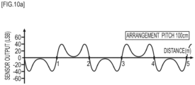
- This simulation test is a simulation regarding sensor output when magnetic sensor 2 (with the sensor height of 200 mm) passes along a laying line where magnetic markers 10 are arrayed. Results of the simulation test are as in FIG. 10a to FIG. 10e and FIG. 11 described below.
- FIG. 10a to FIG. 10e each corresponds to the laying specification for magnetic markers 10 in which their magnetic polarities are alternately switched along the road.
- the arrangement pitch between magnetic markers 10 is varied for each of the drawings in FIG. 10a to 10e .
- the arrangement pitch is 100 cm in FIG. 10a , 50 cm in FIG. 10b , 30 cm in FIG. 10c , 20 cm in FIG. 10d , and 10 cm in FIG. 10e .
- gap G between adjacent magnetic markers 10 is 90 cm.
- the state is almost such that each magnetic marker 10 is magnetically isolated, and it can be predicted that degree of interference between the magnetic fields of respective magnetic markers 10 become small as negligible.
- the arrangement pitch is 10 cm in FIG. 10e
- the state becomes such that magnetic markers 10 adjacent to each other are circumscribed, and it can be predicted that the degree of interference between the magnetic fields becomes the highest.
- the appearing sensor output waveform is close to a sine wave.
- the positive-negative ridges of respective magnetic markers 10 interfere with each other and become indistinctive and integrated.
- the position of each zero-cross in the waveform corresponds to the position directly above each magnetic marker 10.
- the magnetic fields of respective magnetic markers 10 mutually interfere with each other and become integrated, and the sensor output waveform is a waveform close to a sine wave.
- the arrangement pitch is equal to or larger than 50 cm, mutual interference between the magnetic fields of respective magnetic markers 10 is insufficient, and the sensor output waveform is not an integrated waveform of a sine wave.
- FIG. 11 depicts simulation results indicating a relation between the arrangement pitch between magnetic markers 10 (horizontal axis) and the magnitude of sensor output (p-p) (vertical axis). While the magnitude of sensor output (p-p) when the arrangement pitch is 50 cm is not much different from that when the arrangement pitch is 100 cm, as the arrangement pitch approaches 30 cm, the sensor output (p-p) gradually increases. Then, the sensor output (p-p) has a peak value when the arrangement pitch is 25 cm or so. When the arrangement pitch is shorter, the sensor output (p-p) again decreases. Then, when the arrangement pitch is shorter than 20 cm, the sensor output (p-p) is even smaller than those when the arrangement pitch is 50 cm or 100 cm. For example, the sensor output when the arrangement pitch is 10 cm is significantly small compared with the sensor output when the arrangement pitch is 50 cm or 100 cm.
- FIG. 12a to FIG. 12c are diagrams each schematically depicting magnetic fields formed on a periphery of magnetic markers 10.
- FIG. 12a corresponds to the arrangement pitch of 100 cm
- FIG. 12b corresponds to the arrangement pitch of 10 cm
- FIG. 12c corresponds to the arrangement pitch of 20 cm.
- the loop of the magnetic field when the arrangement pitch is 10 cm is smaller than the loop of the magnetic field when the arrangement pitch is 100 cm, as in FIG. 12a and FIG. 12b .
- the loop of the magnetic field when the arrangement pitch is 20 cm is larger than the loop of the magnetic field when the arrangement pitch is 100 cm, as in FIG. 12a and FIG. 12c .
- the inventors have considered that with the loop of the magnetic field decreased when the arrangement pitch is 10 cm, the intensity of the magnetic field acting on magnetic sensor 2 positioned higher than road surface 53 is impaired to decrease the sensor output. Also, it has been considered that when the arrangement pitch is 20 cm, with the loop of the magnetic field increased, the magnetic field acting on magnetic sensor 2 positioned higher than road surface 53 is enhanced to increase the sensor output.
- the arrangement pitch between magnetic markers 10 (refer to FIG. 7 ) is appropriately set so that the magnetic fields of two magnetic markers 10 adjacent to each other and having different magnetic polarities mutually interfere with each other.
- the size of the loop of the magnetic field is expanded more than the case of a single magnetic marker 10, and the magnetic field acting on magnetic sensor 2 at the position higher than road surface 53 is intensified.
- magnetic marker system 1 of the present embodiment while reducing magnetic force (for example, magnetic flux density of the surface or the like) of magnetic marker 10 itself, the intensity of the magnetic field acting on magnetic sensor 2 attached to vehicle 5 can be improved.
- This magnetic marker system 1 is a system having excellent characteristics capable of detecting magnetic marker 10 on the vehicle 5 side with high reliability while reducing the magnetic force of magnetic marker 10.
- a shape specification of magnetic marker 10 is not limited to the sheet shape.
- a columnar magnetic marker having, for example, the diameter of 20 mm and the height of 28 mm, may be used.
- an upper-surface shape of the magnetic marker is not limited to a circular shape, but a triangular shape, a rectangular shape, a polygonal shape more than a pentagon, or the like may be adopted.
- the upper-surface shape of the magnetic marker may preferably be a point-symmetric shape with respect to a center or barycenter or a shape close to be point-symmetric.
- the upper-surface shape of the magnetic marker may be a shape having its outer perimeter formed at least partially with a curve, and may be a shape exhibiting an outer-peripheral shape smoothly configured only of a curve without a corner part.
- magnetic marker 10 in the present embodiment
- a type of magnet is not limited to the present embodiment.
- the magnet may be a ferrite plastic magnet or a magnet made of neodymium or the like.
- magnetic marker 10 without an accommodation case is exemplarily described in the present embodiment
- a magnetic marker with a magnet accommodated in an accommodation case may be used.
- a magnet made of neodymium or the like whose anti-corrosiveness is insufficient is required to be accommodated in the accommodation case with high airtightness or fluid-tightness.
- Condition 1 to Condition 3 three types of conditions, the above-described Condition 1 to Condition 3, are exemplarily described as conditions for selectively determining the arrangement pitch between magnetic markers 10 and the arrangement pitch satisfying all of Condition 1 to Condition 3 is set. Either one or two of the three types of conditions may be adopted.
- the condition to be adopted may be any of Condition 1 to Condition 3.
- Condition 3 there is a possibility that the lower limit of the arrangement pitch is not defined only with this condition.
- a condition is preferably combined, such as the condition in which gap G (G>0) can be ensured between magnetic markers 10 adjacent to each other.
- the above-described Condition 1 indicating that the arrangement pitch is within the range of being equal to or larger than 2/3 Hmax and equal to or smaller than 3/2 ⁇ Hmax
- the above-described Condition 2 indicating that the length of gap G between magnetic markers 10 adjacent to each other is within the range of being equal to or larger than 1/3 ⁇ Hmax and equal to or smaller than 1 ⁇ Hmax
- a condition regarding the arrangement pitch in place of the above-described Condition 1, a condition may be set in which the arrangement pitch has a length corresponding to a length smaller than a double of the attachment height of magnetic sensor 2. If the arrangement pitch is equal to or larger than the double of the attachment height, the degree of interference between the magnetic fields of magnetic markers 10 adjacent to each other is small, and there is a possibility that the effect of intensifying the magnetic field acting on magnetic sensor 2 is not sufficiently exerted.
- the above-described Condition 2 is exemplarily described in which the length of gap G is within the range of being equal to or larger than 1/3 ⁇ Hmax and equal to or smaller than 1 ⁇ Hmax.
- Hmax which the an upper-limit height of 100 mm to 250 mm assumed as the sensor height
- an intermediate attachment height may be set.
- an attachment height of magnetic sensor 2 in a general type of vehicles produced in the greatest numbers may be set as the attachment height as a reference.
- An RF-ID tag may be attached to at least a part of magnetic markers 10 arrayed along the road.
- the RF-ID tag can be used as an information providing part which provides information for identifying magnetic marker 10.
- a vehicle including a tag reader unit communicable with the RF-ID tag can obtain information wirelessly transmitted by the RF-ID tag. This information may be identification information of the RF-ID tag.
- a database storing position information of magnetic markers 10 linked to this identification information may be provided in a server device accessible from vehicle 5 via wireless communication, or in vehicle 5.
- the position information of magnetic marker 10 can be identified.
- transmission information of the RF-ID tag the position information of corresponding magnetic marker 10 itself may be used.
- the number of times of passing over magnetic markers 10 may be counted. If the arrangement pitch between magnetic markers 10 is defined, the number of times of passing over magnet markers 10 is multiplied by the arrangement pitch, distance travelled with reference to the identified position can be calculated with high accuracy.
- magnetic sensor 2 having sensitivity in the longitudinal direction (forwarding direction) of vehicle 5 is exemplarily described in the present embodiment
- a magnetic sensor having sensitivity in the vehicle-width direction may be used, or a magnetic sensor having sensitivity in the vertical direction may be used.
- a magnetic sensor having sensitivity in two axial directions of the vehicle-width direction and the forwarding direction or two axial direction of the forwarding direction and the vertical direction may be adopted.
- a magnetic sensor having sensitivity in three axial directions of the vehicle-width direction, the forwarding direction, and the vertical direction may be adopted.
- the magnitude of magnetism and the acting direction of magnetism can be measured, and a magnetic vector can be generated.
- accuracy of detection of magnetic marker 10 may be improved.
- the present embodiment is an example based on magnetic marker system 1 of the first embodiment, with changes in conditions for determining the arrangement pitch between magnetic markers 10. Details of this are described with reference to FIG. 13 and FIG. 14 .
- an index value indicating a degree of similarity between a sensor output waveform and a sine wave is used.
- the index value for example, a coefficient of correlation between the sensor output waveform and a sine wave, an error amount between the sensor output waveform and a sine wave, and so forth can be used.
- a coefficient of correlation a coefficient of correlation between data series xi (the number of pieces of data is n), which is sampling data of a sensor output waveform for one cycle in FIG. 13a , and data series yi (the number of pieces of data is n), which is sampling data of a sine wave for one cycle in FIG. 13b .
- the sine wave of FIG. 13b has its phase and cycle matched with the sensor output waveform in FIG. 13a as a target for investigating the correlation, and there is a match regarding the interval and position of a zero-cross .
- Coefficient of correlation r between data series xi of the sensor output waveform in FIG. 13a and data series yi of the sine wave of FIG. 13b can be calculated by, for example, the following equation.
- Sxy is a covariance between data series xi and data series yi
- Sx is a standard deviation of data series xi
- Sy is a standard deviation of data series yi
- xav is an average value of data series xi
- yav is an average value of data series yi.
- the above-described coefficient of correlation r is 1.
- coefficient of correlation r gradually decreases.
- FIG. 14a and FIG. 14b when the difference between the sensor output waveform and a sine wave is large and coefficient of correlation r is small, the magnetic field acting on magnetic sensor 2 is weak, and the sensor output tends to decrease. Also, even if the sensor output waveform is close to the waveform of a sine wave and coefficient of correlation r is approximately 1, if the arrangement pitch is too short, the sensor output is small.
- the longest arrangement pitch may be set as the arrangement pitch when magnetic markers 10 are laid.
- the sensor output waveform exhibits a sine wave when coefficient of correlation r is equal to or larger than a threshold value such as 0.8.
- the sensor output waveform corresponds to a distribution of intensities of magnetic fields (magnitudes of magnetism) acting on the magnetic sensor.
- the sensor output waveform exhibits a sine wave when, for example, 0.9 is set as the threshold value regarding the above-described coefficient of correlation r and coefficient of correlation r is equal to or larger than the threshold value.
- the threshold value is, for example, 0.8
- degree of matching between the sensor output waveform and the sine wave can be more strictly determined.
- the arrangement pitch which is too short while coefficient of correlation r is approximately 1 thereby decreasing the sensor output, for example, a range of being equal to or larger than 0.8 and smaller than 0.9, a range of being equal to or larger than 0.9 and smaller than 0.95, or the like may be set as a range of coefficient of correlation r.
- the threshold value smaller than 1 as an upper limit of coefficient of correlation r, a narrow arrangement pitch which causes a decrease in sensor output can be eliminated in advance.
- the sensor output waveform required to calculate coefficient of correlation r can be calculated by a simulation calculation.
- a test section where, for example, ten magnetic markers 10 or so are arrayed may be provided, and data series xi of the sensor output waveform may be obtained by actual measurements by magnetic sensor 2 in this test section.
- Data values of a sine wave can be obtained by calculation or the like.
- the index value indicating the degree of similarity between the sensor output waveform and a sine wave coefficient of correlation r between the sensor output waveform and the sine wave is exemplarily described.
- an error amount may be adopted, such as a sum total of minimum square errors between the sensor output waveform and a normalized sine wave. As this error amount is smaller, the similarity between the sensor output waveform and the sine wave is higher.
- this error amount is subjected to a threshold process and the error amount is smaller than a preset threshold, it is preferably determined that the sensor output waveform exhibits a sine-wave waveform.
- the sensor output waveform in the case of 20 cm may become a smoother waveform close to a sine waveform. This is because a gap between the magnetic marker and the magnetic sensor is appropriate in the case of 20 cm.
- determination conditions for the threshold process may be changed in accordance with the attachment height of the magnetic sensor. For example, when the attachment height of the magnetic sensor is low, the determination conditions for the above-described threshold process are preferably mitigated, compared with the case in which this attachment height is high.
Landscapes
- Engineering & Computer Science (AREA)
- Physics & Mathematics (AREA)
- General Physics & Mathematics (AREA)
- Automation & Control Theory (AREA)
- Architecture (AREA)
- Civil Engineering (AREA)
- Structural Engineering (AREA)
- Mechanical Engineering (AREA)
- Transportation (AREA)
- Human Computer Interaction (AREA)
- Remote Sensing (AREA)
- Radar, Positioning & Navigation (AREA)
- Aviation & Aerospace Engineering (AREA)
- Electromagnetism (AREA)
- General Engineering & Computer Science (AREA)
- Control Of Position, Course, Altitude, Or Attitude Of Moving Bodies (AREA)
- Road Signs Or Road Markings (AREA)
- Traffic Control Systems (AREA)
Description
- The present invention relates to a magnetic marker system including magnetic markers laid on or in a road so that they can be detected on a vehicle side traveling on the road.
- Conventionally, vehicular magnetic marker detection systems using magnetic markers laid on a road have been known (for example, refer to Patent Literature 1) . These magnetic marker detection systems have an object of providing various driving assists, such as automatic steering control or lane departure warning using the magnetic markers, by taking vehicles including magnetic sensors as targets.
-
DE 100 19 779 A1 discloses a sensor for a test vehicle which is movable along a predetermined track provided with a series of marker magnets. The sensor has an antenna device from which a signal is generated when passing a marker magnet. -
JP 2002 260154 A -
US 3 609 678 A discloses a magnet installation on a roadway for providing control information to vehicles traveling on the roadway comprising at least one preformed polymer-based magnet that is installed in a lane of travel of the roadway and that comprises a tough organic polymeric matrix that has a thickness of at least about 25 mils and particles of magnetic material. -
WO 2017/187881 A1 discloses a driving assistance system that comprises: magnetic markers that are magnetically detectable and that are laid on a travel path so as to be capable of providing code information to the vehicle side; a vehicle configured so as to be capable of magnetically detecting the magnetic markers and reading the code information; and a base station configured so as to receive code information from the vehicle that has read the code information and respond with corresponding information. - Patent Literature 1:
Japanese Unexamined Patent Application Publication No. 2005-202478 - However, the above-described conventional vehicular magnetic marker detection systems have the following problem. That is, since a magnetic sensor on a vehicle side is attached at a high position on the order of 100 mm to 250 mm from a road surface, magnetic force of a magnetic marker is required to be intensified to some extent. On the other hand, if the magnetic force of the magnetic marker is intensified, a metallic object such as a nail or bolt falling on the road surface is attracted to possibly cause a trouble such as a blowout of a vehicle's tire.
- The present invention was made in view of the above-described conventional problem, and is to provide a magnetic marker system for allowing a magnetic marker to be detected with high reliability on a vehicle side while magnetic force of the magnetic marker is reduced.
- The present invention provides a magnetic marker system according to
claim 1. Further embodiments of the present invention are disclosed in the dependent claims. - In the magnetic marker system of the present invention, the magnetic markers are laid so that the orientations of the magnetic poles are alternately reversed along the road. Furthermore, the magnetic markers in this magnetic marker system are arranged so that the magnetic fields of the magnetic markers adjacent to each other as being spaced with the gap along the road interfere with each other.
- In the magnetic marker system of the present invention, a magnetic field acting on the vehicle side is intensified by using interference between the magnetic fields of the magnetic markers adjacent to each other. If the magnetic field acting on the vehicle side can be intensified by using the interference between the magnetic fields, strength of the magnetic force on a surface of a magnetic marker can be relatively reduced with respect to strength of the magnetic field required on the vehicle side for detection of the magnetic marker.
- As described above, the magnetic marker system of the present invention is a system having an excellent characteristic capable of detecting the magnetic marker on the vehicle side with high reliability while reducing the magnetic force of the magnetic marker.
-
-
FIG. 1 is a descriptive diagram depicting a state in which a vehicle detects a magnetic marker in a first embodiment. -
FIG. 2 is a descriptive diagram depicting a magnetic marker system in the first embodiment. -
FIG. 3 is a diagram depicting the magnetic marker in the first embodiment. -
FIG. 4 is a graph depicting a magnetic field distribution of the magnetic marker in a vertical direction in the first embodiment. -
FIG. 5 is a block diagram depicting an electrical configuration of a magnetic sensor in the first embodiment. -
FIG. 6 is a descriptive diagram of changes in sensor output at time of passing over the magnetic marker in the first embodiment. -
FIG. 7 is a descriptive diagram of an arrangement pitch and gap G between magnetic markers in the first embodiment. -
FIG. 8 is a descriptive diagram of laying specifications for magnetic markers in the first embodiment. -
FIG. 9 is a graph depicting a relation between an attachment height of the magnetic sensor and sensor output (p-p) in the first embodiment. -
FIG. 10a is a graph depicting changes in sensor output in a forwarding direction of the vehicle when the arrangement pitch between the magnetic markers=100 cm in the first embodiment. -
FIG. 10b is a graph depicting changes in sensor output in the forwarding direction of the vehicle when the arrangement pitch between the magnetic markers=50 cm in the first embodiment. -
FIG. 10c is a graph depicting changes in sensor output in the forwarding direction of the vehicle when the arrangement pitch between the magnetic markers=30 cm in the first embodiment. -
FIG. 10d is a graph depicting changes in sensor output in the forwarding direction of the vehicle when the arrangement pitch between the magnetic markers=20 cm in the first embodiment. -
FIG. 10e is a graph depicting changes in sensor output in the forwarding direction of the vehicle when the arrangement pitch between the magnetic markers=10 cm in the first embodiment. -
FIG. 11 is a graph depicting a relation between the arrangement pitch between magnetic markers and sensor output (p-p) in the first embodiment. -
FIG. 12a is a descriptive diagram of magnetic fields formed by a single magnetic marker in the first embodiment. -
FIG. 12b is a descriptive diagram of magnetic fields formed by magnetic markers when the arrangement pitch=10 cm in the first embodiment. -
FIG. 12c is a descriptive diagram of magnetic fields formed by magnetic markers when the arrangement pitch=20 cm in the first embodiment. -
FIG. 13a is a diagram depicting a data series configuring a sensor output waveform in a second embodiment. -
FIG. 13b is a diagram depicting a data series configuring a sine waveform in the second embodiment. -
FIG. 14a is a graph depicting a relation between the arrangement pitch between magnetic markers and a coefficient of correlation in the second embodiment. -
FIG. 14b is a descriptive diagram depicting sensor output (p-p) in a high correlation range in the second embodiment. - Embodiments of the present invention are specifically described by using the following embodiments.
- The present embodiment is an example of
magnetic marker system 1 includingmagnetic markers 10 laid along a road so as to be detectable on avehicle 5 side. Details of this are described by usingFIG. 1 to FIG. 12 . -
Magnetic markers 10 ofFIG. 1 andFIG. 2 are laid, for example, along the center oflane 530 wherevehicle 5 travels.Magnetic markers 10 laid onroad surface 53 in this manner can be detected bymagnetic sensor 2 attached, for example, tovehicle body floor 50 forming a bottom surface ofvehicle 5. Detection signal ofmagnetic marker 10 bymagnetic sensor 2 is inputted to, for example, an ECU or the like, not depicted, on thevehicle 5 side, and can be used for various controls on thevehicle 5 side, such as automatic steering control for lane keeping, driving assist control such as lane departure warning, and automatic traveling control. -
Magnetic marker 10 is, as depicted inFIG. 3 , a flat, circular marker having a diameter of 100 mm and a maximum thickness of approximately 2.0 mm.Magnetic marker 10 includes aflat magnet sheet 11 having a diameter of 100 mm and a thickness of 1.0 mm. Inmagnetic marker 10, both front and back surface sides ofmagnet sheet 11 are each covered withresin mold 12 having a thickness of 0.5 mm.Magnet sheet 11 is a sheet, made of isotropic ferrite rubber magnet, obtained by molding a mixture of magnetic powder made of iron oxide and rubber. Thismagnet sheet 11 has a maximum energy product (BHmax) of 6.4 kJ/cubic meter. - In this
magnetic marker 10, one surface of both front and back surfaces is an N-pole surface, and the other surface is an S-pole surface. Thismagnetic marker 10 does not have a distinction between the front and the back, and either one of a laying mode with the N pole serving as an upper surface and a laying mode with the S pole serving as the upper surface can be alternatively selected (refer toFIG. 2 ). - Installation of
magnetic markers 10 onroad surface 53 is performed by, for example, bonding and fixing with a bonding agent. Note that resin mold may be applied also onto an outer peripheral side surface ofmagnetic marker 10. Also,resin mold 12 on the upper surface side ofmagnet sheet 11 forming part ofroad surface 53 may be a resin mold reinforced with glass fiber. - Here, shape specifications and magnetic specifications of
magnet sheet 11 included inmagnetic marker 10 of the present embodiment are partially depicted in Table 1.[Table 1] Magnet type Ferrite rubber magnet Outer diameter φ 100 mm Thickness 1.0 mm (excluding resin mold) Magnetic flux density Gs of the surface 1 mT - Magnetic field distribution with which
magnetic marker 10 acts in a vertical direction is as inFIG. 4 . The drawing is a semilogarithmic graph indicating simulation results by axisymmetric three-dimensional magneto-static analysis using a finite element method. Note that to perform this computer simulation, a simulation program whose simulation accuracy has been confirmed in advance by demonstrative experiments is used. Furthermore, as for part of data indicated in the drawing, values have been confirmed by demonstrative experiments. -
FIG. 4 is a drawing in which the logarithmic scale for the magnetic flux density of magnetism acting in the vertical direction is set on a vertical axis and a height ofmagnetic marker 10 with reference to its surface in the vertical direction (height from the marker surface) is set on a horizontal axis. In the drawing, the magnetic flux density when the height from the marker surface=0 mm is "magnetic flux density Gs of the surface" in Table 1. In thismagnetic marker 10, in a range of 100 mm to 250 mm assumed as an attachment height of magnetic sensor 2 (hereinafter referred to as a sensor height), the magnetic flux density equal to or higher than 8 microtesla is ensured. -
Magnetic sensor 2 is a MI (Magneto Impedance) sensor of one chip, withMI element 21 and a driving circuit integrated together, as depicted in a block diagram ofFIG. 5 .MI element 21 is an element including amorphous wire (one example of a magneto-sensitive body) 211 made of a CoFeSiB-based alloy and having almost zero magnetostriction andpickup coil 213 wound around thisamorphous wire 211.Magnetic sensor 2 measures voltage generated inpickup coil 213 when a pulse current is applied toamorphous wire 211, thereby detecting magnetism acting onamorphous wire 211 as the magneto-sensitive body. - The driving circuit is configured to include
pulse circuit 23 which supplies pulse current toamorphous wire 211 andsignal processing circuit 25 which samples and outputs a voltage generated atpickup coil 213 at predetermined timing.Pulse circuit 23 is a circuit includingpulse generator 231 which generates a pulse signal as a source of the pulse current.Signal processing circuit 25 is a circuit which picks up an induced voltage ofpickup coil 213 viasynchronous detection 251 which is opened and closed in conjunction with the pulse signal and amplifies the voltage byamplifier 253 with a predetermined amplification factor. A signal amplified by thissignal processing circuit 25 is externally outputted as a sensor signal. - Specifications of this
magnetic sensor 2 are partially depicted in Table 2.[Table 2] Measurement range ±0.6 mT Magnetic flux resolution 0.02 µT Sampling frequency 3 kHz -
Magnetic sensor 2 is a sensor with high sensitivity in which the measurement range of the magnetic flux density is ±0.6 millitesla and the magnetic flux resolution in the measurement range is 0.02 microtesla. This high sensitivity is achieved byMI element 21 using the MI effect in which the impedance ofamorphous wire 211 sensitively changes in response to an external magnetic field. Here, as described above,magnetic marker 10 acts on a position with the height of 100 mm to 250 mm, which is an assumed range of the sensor height, with magnetism having at least the magnetic flux density of 8 microtesla (refer toFIG. 4 ). According tomagnetic sensor 2 having the magnetic flux resolution of 0.02 microtesla (refer toFIG. 2 ), thismagnetic marker 10 can be detected with high reliability. -
Magnetic sensor 2 has sensitivity in a longitudinal direction ofamorphous wire 211. In a configuration of the present embodiment,magnetic sensor 2 is vehicle-mounted so that the longitudinal direction ofamorphous wire 211 goes along a longitudinal direction ofvehicle 5. Thismagnetic sensor 2 has sensitivity in a forwarding direction ofvehicle 5, and can measure a component of a magnetic field acting in this direction. Note thatmagnetic sensor 2 of the present embodiment is configured so that its output (hereinafter, sensor output) has a positive value whenvehicle 5 approaches N-polemagnetic marker 10. - As for the component along the forwarding direction of
vehicle 5 of the magnetic field acting onmagnetic sensor 2, an acting direction is reversed between a position beforemagnetic marker 10 and a position after passing overmagnetic marker 10. And, at the position directly abovemagnetic marker 10, the magnitude of the component along the forwarding direction ofvehicle 5 of the magnetic field acting onmagnetic sensor 2 becomes zero. For example, whenvehicle 5 passes over N-polemagnetic marker 10, as inFIG. 6 , the sensor output with the positive value gradually increases to become a maximum value, and is then changed to decrease before the position directly abovemagnetic marker 10 and gradually diminish. Then, after the sensor output becomes zero at the position directly abovemagnetic marker 10, as the vehicle goes away frommagnetic marker 10, the sensor output with a negative value gradually increases to a negative side and becomes a minimum value. Then, as the vehicle further goes away frommagnetic marker 10, the sensor output with the negative value becomes closer to zero. In this manner, the waveform of the sensor output whenvehicle 5 passes over magnetic marker 10 (hereinafter, sensor output waveform) exhibits a zero-cross at the position directly abovemagnetic marker 10, and becomes a waveform with both positive and negative ridges forming a point-symmetric relation with respect to this zero-cross. Note in a graph ofFIG. 6 that positions ofvehicle 5 in the forwarding direction are defined on the horizontal axis and sensor outputs are defined on the vertical axis. A unit of sensor output in the drawing are minimum bit (LSB) when the sensor output is digitized. All units of sensor output or sensor output (p-p) in the drawings of the present embodiment are these minimum bits (LSB). - In
magnetic marker system 1 of the present embodiment, as inFIG. 7 ,magnetic markers 10 are arranged at an arrangement pitch of 20 cm along the road. Since eachmagnetic marker 10 has the diameter of 100 mm (10 cm), a gap (gap) G between twomagnetic markers 10 adjacent to each other along the road is 10 cm. Furthermore, in a configuration of the present embodiment,magnetic marker 10 with the N pole on its upper surface andmagnetic marker 10 with the S pole on its upper surface are alternately arranged so that orientations of magnetic poles are alternately reversed along the road, and magnetic polarities ofmagnetic markers 10 are alternately switched. In the present embodiment, by setting a relatively narrow arrangement pitch betweenmagnetic markers 10 and alternately switching the magnetic polarities ofmagnetic markers 10, intensity of the magnetic field (magnitude of magnetism) acting onmagnetic sensor 2 is enhanced. - Next, described with reference to
FIG. 8 andFIG. 9 is that the intensity of the magnetic field acting onmagnetic sensor 2 can be improved by laying mode ofmagnetic markers 10 as described above.FIG. 8 depicts four types of laying specification.FIG. 9 exemplarily depicts a relation between the sensor height (horizontal axis) and the sensor output (p-p) (vertical axis) for each laying specification. Note that the sensor output (p-p) indicates peak-to-peak (amplitude) of the sensor output waveform. - Four types of laying specification in
FIG. 8 are as follows. - (First Laying Specification) Laying specification of the present embodiment in which
magnetic markers 10 are arranged every 20 cm along the road so that the magnetic polarities ofmagnetic markers 10 are alternately switched. As described above, since eachmagnetic marker 10 has the diameter of 10 cm, length of gap G between twomagnetic markers 10 adjacent to each other along the road is 10 cm (refer toFIG. 7 ). - (Second Laying Specification) Laying specification in which S-pole
magnetic markers 10 are arranged every 20 cm along the road without switching of the magnetic polarities ofmagnetic markers 10. - (Third Laying Specification) Laying specification in which
magnetic markers 10 are arranged every 10 cm along the road so that the magnetic polarities ofmagnetic markers 10 are alternately switched. Since eachmagnetic marker 10 has the diameter of 10 cm, the state becomes such that twomagnetic markers 10 adjacent to each other along the road are circumscribed without the gap. - (Fourth Laying Specification) Laying specification in which
magnetic markers 10 adjacent to each other are arranged so as to be sufficiently separated and eachmagnetic marker 10 is magnetically isolated. - According to
FIG. 9 , the sensor output (p-p) in the above-described first laying specification is maximum. In particular, at each ofsensor heights 150 mm, 200 mm, and 250 mm which belong to 100 mm to 250 mm assumed as sensor heights, it is significant that the sensor output tends to become large in the first laying specification compared with the other laying specifications. - As described above, in the first laying specification, the sensor output tends to be larger than that in the fourth laying specification in which
magnetic markers 10 are magnetically isolated from one another. On the other hand, in the second laying specification without alternate switching in magnetic polarities, the sensor output is minimum among the above-described four laying specifications. Also, in the third laying specifications in whichmagnetic markers 10 are arrayed without the gap although the magnetic polarities are switched, the sensor output is smaller than that in the fourth laying specification in whichmagnetic markers 10 are magnetically isolated from one another. - The inventors have considered that the sensor output is varied as described above because the magnetic fields of
magnetic markers 10 adjacent to each other interfere with each other. Furthermore, as for the first and third laying specifications in which the magnetic polarities ofmagnetic markers 10 are alternately switched, the inventors have considered that the sensor output is varied due to a difference in arrangement pitch. In more detail, the inventors have considered that, when the arrangement pitch is 20 cm, the magnetic field acting onmagnetic sensor 2 is intensified due to interference between the magnetic fields ofmagnetic markers 10 adj acent to each other to increase the sensor output. Furthermore, the inventors have considered that when the arrangement pitch is 10 cm, the magnetic field acting onmagnetic sensor 2 is weakened due to interference between the magnetic fields ofmagnetic markers 10 adjacent to each other to decrease the sensor output. - The inventors have conducted a simulation test regarding sensor outputs to investigate a relation between degree of mutual interference between the magnetic fields of
magnetic markers 10 adjacent to each other and magnitude of sensor output. This simulation test is a simulation regarding sensor output when magnetic sensor 2 (with the sensor height of 200 mm) passes along a laying line wheremagnetic markers 10 are arrayed. Results of the simulation test are as inFIG. 10a to FIG. 10e andFIG. 11 described below. - In the simulation test, first, by using the above-described simulation program, the magnetic field distribution formed by
magnetic markers 10 is calculated.FIG. 10a to FIG. 10e each depicts simulation result of the sensor output waveform predicted whenmagnetic sensor 2 moves along the above-described laying line in this magnetic field distribution when the sensor height=200 mm. -
FIG. 10a to FIG. 10e each corresponds to the laying specification formagnetic markers 10 in which their magnetic polarities are alternately switched along the road. On the other hand, the arrangement pitch betweenmagnetic markers 10 is varied for each of the drawings inFIG. 10a to 10e . The arrangement pitch is 100 cm inFIG. 10a , 50 cm inFIG. 10b , 30 cm inFIG. 10c , 20 cm inFIG. 10d , and10 cm inFIG. 10e . - When the arrangement pitch is 100 cm in
FIG. 10a , gap G between adjacentmagnetic markers 10 is 90 cm. In this case, the state is almost such that eachmagnetic marker 10 is magnetically isolated, and it can be predicted that degree of interference between the magnetic fields of respectivemagnetic markers 10 become small as negligible. On the other hand, when the arrangement pitch is 10 cm inFIG. 10e , the state becomes such thatmagnetic markers 10 adjacent to each other are circumscribed, and it can be predicted that the degree of interference between the magnetic fields becomes the highest. - In the sensor output waveform when the arrangement pitch is 100 cm in
FIG. 10a , interference between the magnetic fields of respectivemagnetic markers 10 hardly occurs, and eachmagnetic marker 10 is magnetically isolated. In this case, positive-negative ridges of the sensor output whenmagnetic sensor 2 with sensitivity in the forwarding direction ofvehicle 5 passes overmagnetic markers 10 individually appear for eachmagnetic marker 10. Of the positive-negative ridges configuring the sensor output waveform, the position of a zero-cross corresponds to the position directly above eachmagnetic marker 10. - On the other hand, in the sensor output waveform when the arrangement pitch is 10 cm in
FIG. 10e , the appearing sensor output waveform is close to a sine wave. In this sensor output waveform, the positive-negative ridges of respectivemagnetic markers 10 interfere with each other and become indistinctive and integrated. Note that also in the sensor output waveform inFIG. 10e , the position of each zero-cross in the waveform corresponds to the position directly above eachmagnetic marker 10. - Among intermediate arrangement pitches in
FIG. 10b to FIG. 10d , in the sensor output waveform inFIG. 10b when the arrangement pitch is 50 cm, interference occurs between the positive-negative ridges ofmagnetic markers 10 adjacent to each other, but the sensor output waveform is not a waveform of a sine wave. On the other hand, inFIG. 10c andFIG. 10d in which the arrangement pitches are 30 cm and 20 cm, respectively, as with the case in which the arrangement pitch is 10 cm, the sensor output waveform is a waveform close to a sine wave. - As described above, in
magnetic markers 10 of the present embodiment, in a range in which the arrangement pitch is equal to or smaller than 30 cm, the magnetic fields of respectivemagnetic markers 10 mutually interfere with each other and become integrated, and the sensor output waveform is a waveform close to a sine wave. On the other hand, in a range in which the arrangement pitch is equal to or larger than 50 cm, mutual interference between the magnetic fields of respectivemagnetic markers 10 is insufficient, and the sensor output waveform is not an integrated waveform of a sine wave. -
FIG. 11 depicts simulation results indicating a relation between the arrangement pitch between magnetic markers 10 (horizontal axis) and the magnitude of sensor output (p-p) (vertical axis). While the magnitude of sensor output (p-p) when the arrangement pitch is 50 cm is not much different from that when the arrangement pitch is 100 cm, as the arrangement pitch approaches 30 cm, the sensor output (p-p) gradually increases. Then, the sensor output (p-p) has a peak value when the arrangement pitch is 25 cm or so. When the arrangement pitch is shorter, the sensor output (p-p) again decreases. Then, when the arrangement pitch is shorter than 20 cm, the sensor output (p-p) is even smaller than those when the arrangement pitch is 50 cm or 100 cm. For example, the sensor output when the arrangement pitch is 10 cm is significantly small compared with the sensor output when the arrangement pitch is 50 cm or 100 cm. - The inventors have considered the reason why this tendency of the sensor output occurs as follows. That is, the inventors have considered that size of a loop of a magnetic field formed around each
magnetic marker 10 varies (FIG. 12a to FIG. 12c ) in accordance with length of the arrangement pitch betweenmagnetic markers 10, thereby causing the magnitude of the sensor output to be varied. Here,FIG. 12a to FIG. 12c are diagrams each schematically depicting magnetic fields formed on a periphery ofmagnetic markers 10.FIG. 12a corresponds to the arrangement pitch of 100 cm,FIG. 12b corresponds to the arrangement pitch of 10 cm, andFIG. 12c corresponds to the arrangement pitch of 20 cm. - The loop of the magnetic field when the arrangement pitch is 10 cm is smaller than the loop of the magnetic field when the arrangement pitch is 100 cm, as in
FIG. 12a andFIG. 12b . Also, the loop of the magnetic field when the arrangement pitch is 20 cm is larger than the loop of the magnetic field when the arrangement pitch is 100 cm, as inFIG. 12a andFIG. 12c . The inventors have considered that with the loop of the magnetic field decreased when the arrangement pitch is 10 cm, the intensity of the magnetic field acting onmagnetic sensor 2 positioned higher thanroad surface 53 is impaired to decrease the sensor output. Also, it has been considered that when the arrangement pitch is 20 cm, with the loop of the magnetic field increased, the magnetic field acting onmagnetic sensor 2 positioned higher thanroad surface 53 is enhanced to increase the sensor output. - In the present embodiment, in view of the results of
FIG. 10 andFIG. 11 , as the arrangement pitch betweenmagnetic markers 10, the arrangement pitch=20 cm is set, which satisfies the following three conditions. - (Condition 1) With reference to Hmax=250 mm, which is an upper-limit height of 100 mm to 250 mm assumed as the sensor height, the arrangement pitch is within a range of being equal to or larger than 2/3 Hmax and equal to or smaller than 3/2× Hmax.
- (Condition 2) With reference to Hmax=250 mm, which is the upper-limit height of 100 mm to 250 mm assumed as the sensor height, the length of gap G between
magnetic markers 10 adjacent to each other is within a range of being equal to or larger than 1/3× Hmax and equal to or smaller than 1× Hmax. - (Condition 3) The magnitude of the magnetic field with which
magnetic markers 10 arrayed along the road including twomagnetic markers 10 adjacent to each other act on the vehicle side exhibits a distribution of a sine waveform along the road. Here, the magnitude of the magnetic field acting on the vehicle side means a maximum value in the magnetic field distribution in a vehicle-width direction. Therefore, "exhibits a distribution of a sine waveform along the road" described above corresponds to the following: the sensor output waveform bymagnetic sensor 2 passing directly abovemagnetic markers 1 arrayed along the road is a sine wave. - As for the above-described
Condition 1, the arrangement pitch smaller than 2/3× Hmax=167 mm belongs to a left region of a peak value in the graph inFIG. 11 , andmagnetic markers 10 adjacent to each other are too close and there is a possibility of a decrease in sensor output. On the other hand, the arrangement pitch exceeding 3/2× Hmax=375 mm belongs to a right region of the graph inFIG. 11 , andmagnetic markers 10 adjacent to each other are too away and therefore there is a possibility of a decrease in sensor output. - Also, as for the above-described
Condition 2, when the length of gap G betweenmagnetic markers 10 adjacent to each other is smaller than 1/3× Hmax=83 mm,magnetic markers 10 adjacent to each other are too close and there is a possibility that the sensor output becomes even small. On the other hand, when the length of gap G betweenmagnetic markers 10 adjacent to each other exceeds 1× Hmax=250 mm,magnetic markers 10 adjacent to each other are too away and therefore there is a possibility of a decrease in sensor output. - Furthermore, as for the above-described Condition 3, when the magnetic field distribution (distribution of magnitudes of magnetism) with which
magnetic markers 10 arrayed along the road act onmagnetic sensor 2 is diverged from a sine waveform, there is a possibility thatmagnetic markers 10 arrayed along the road are each magnetically isolated. In this state in which eachmagnetic marker 10 is isolated, the degree of interference between the magnetic fields of twomagnetic markers 10 adjacent to each other is not sufficient, and there is a possibility that the sensor output becomes small, as in the right region of the graph inFIG. 11 . - As described above, in
magnetic marker system 1, the arrangement pitch between magnetic markers 10 (refer toFIG. 7 ) is appropriately set so that the magnetic fields of twomagnetic markers 10 adjacent to each other and having different magnetic polarities mutually interfere with each other. In thismagnetic marker system 1, by mutual interference between the magnetic fields ofmagnetic markers 10 adjacent to each other, the size of the loop of the magnetic field is expanded more than the case of a singlemagnetic marker 10, and the magnetic field acting onmagnetic sensor 2 at the position higher thanroad surface 53 is intensified. - According to
magnetic marker system 1 of the present embodiment, while reducing magnetic force (for example, magnetic flux density of the surface or the like) ofmagnetic marker 10 itself, the intensity of the magnetic field acting onmagnetic sensor 2 attached tovehicle 5 can be improved. Thismagnetic marker system 1 is a system having excellent characteristics capable of detectingmagnetic marker 10 on thevehicle 5 side with high reliability while reducing the magnetic force ofmagnetic marker 10. - Note that while a sheet-shape one is exemplarily described as
magnetic marker 10 in the present embodiment, a shape specification ofmagnetic marker 10 is not limited to the sheet shape. For example, a columnar magnetic marker having, for example, the diameter of 20 mm and the height of 28 mm, may be used. Also, an upper-surface shape of the magnetic marker is not limited to a circular shape, but a triangular shape, a rectangular shape, a polygonal shape more than a pentagon, or the like may be adopted. Furthermore, the upper-surface shape of the magnetic marker may preferably be a point-symmetric shape with respect to a center or barycenter or a shape close to be point-symmetric. The upper-surface shape of the magnetic marker may be a shape having its outer perimeter formed at least partially with a curve, and may be a shape exhibiting an outer-peripheral shape smoothly configured only of a curve without a corner part. - Also, while one using the ferrite rubber magnet is exemplarily described as
magnetic marker 10 in the present embodiment, a type of magnet is not limited to the present embodiment. The magnet may be a ferrite plastic magnet or a magnet made of neodymium or the like. Furthermore, whilemagnetic marker 10 without an accommodation case is exemplarily described in the present embodiment, a magnetic marker with a magnet accommodated in an accommodation case may be used. For example, a magnet made of neodymium or the like whose anti-corrosiveness is insufficient is required to be accommodated in the accommodation case with high airtightness or fluid-tightness. - Note in the present embodiment that three types of conditions, the above-described
Condition 1 to Condition 3, are exemplarily described as conditions for selectively determining the arrangement pitch betweenmagnetic markers 10 and the arrangement pitch satisfying all ofCondition 1 to Condition 3 is set. Either one or two of the three types of conditions may be adopted. The condition to be adopted may be any ofCondition 1 to Condition 3. However, as for Condition 3, there is a possibility that the lower limit of the arrangement pitch is not defined only with this condition. Thus, for example, a condition is preferably combined, such as the condition in which gap G (G>0) can be ensured betweenmagnetic markers 10 adjacent to each other. - In the present embodiment, as conditions for selecting the arrangement pitch, the above-described
Condition 1 indicating that the arrangement pitch is within the range of being equal to or larger than 2/3 Hmax and equal to or smaller than 3/2× Hmax, the above-describedCondition 2 indicating that the length of gap G betweenmagnetic markers 10 adjacent to each other is within the range of being equal to or larger than 1/3× Hmax and equal to or smaller than 1× Hmax, and so forth are exemplarily described. As a condition regarding the arrangement pitch, in place of the above-describedCondition 1, a condition may be set in which the arrangement pitch has a length corresponding to a length smaller than a double of the attachment height ofmagnetic sensor 2. If the arrangement pitch is equal to or larger than the double of the attachment height, the degree of interference between the magnetic fields ofmagnetic markers 10 adjacent to each other is small, and there is a possibility that the effect of intensifying the magnetic field acting onmagnetic sensor 2 is not sufficiently exerted. - Also, in the present embodiment, as the condition regarding gap G between
magnetic markers 10 adjacent to each other, the above-describedCondition 2 is exemplarily described in which the length of gap G is within the range of being equal to or larger than 1/3× Hmax and equal to or smaller than 1× Hmax. As the attachment height as a reference, in place of Hmax, which the an upper-limit height of 100 mm to 250 mm assumed as the sensor height, an intermediate attachment height may be set. Furthermore, an attachment height ofmagnetic sensor 2 in a general type of vehicles produced in the greatest numbers may be set as the attachment height as a reference. - An RF-ID tag may be attached to at least a part of
magnetic markers 10 arrayed along the road. The RF-ID tag can be used as an information providing part which provides information for identifyingmagnetic marker 10. A vehicle including a tag reader unit communicable with the RF-ID tag can obtain information wirelessly transmitted by the RF-ID tag. This information may be identification information of the RF-ID tag. For example, a database storing position information ofmagnetic markers 10 linked to this identification information may be provided in a server device accessible fromvehicle 5 via wireless communication, or invehicle 5. In this case, whenmagnetic marker 10 is detected, by using the identification information received from the RF-ID tag, the position ofmagnetic marker 10 can be identified. As transmission information of the RF-ID tag, the position information of correspondingmagnetic marker 10 itself may be used. - When the configuration is adopted in which the RF-ID tag is attached to a part of
magnetic markers 10 to allow a position of correspondingmagnetic marker 10 to be identified as described above, with reference tomagnetic marker 10 with its position identified, the number of times of passing over magnetic markers 10 (the number of times of detection) may be counted. If the arrangement pitch betweenmagnetic markers 10 is defined, the number of times of passing overmagnet markers 10 is multiplied by the arrangement pitch, distance travelled with reference to the identified position can be calculated with high accuracy. - While
magnetic sensor 2 having sensitivity in the longitudinal direction (forwarding direction) ofvehicle 5 is exemplarily described in the present embodiment, a magnetic sensor having sensitivity in the vehicle-width direction may be used, or a magnetic sensor having sensitivity in the vertical direction may be used. Furthermore, for example, a magnetic sensor having sensitivity in two axial directions of the vehicle-width direction and the forwarding direction or two axial direction of the forwarding direction and the vertical direction may be adopted. For example, a magnetic sensor having sensitivity in three axial directions of the vehicle-width direction, the forwarding direction, and the vertical direction may be adopted. With the use of a magnetic sensor having sensitivity in a plurality of axial directions, the magnitude of magnetism and the acting direction of magnetism can be measured, and a magnetic vector can be generated. By using a difference between magnetic vectors and a change ratio of the difference in the forwarding direction, accuracy of detection ofmagnetic marker 10 may be improved. - The present embodiment is an example based on
magnetic marker system 1 of the first embodiment, with changes in conditions for determining the arrangement pitch betweenmagnetic markers 10. Details of this are described with reference toFIG. 13 andFIG. 14 . - In the magnetic marker system of the present embodiment, to selectively set the arrangement pitch, an index value indicating a degree of similarity between a sensor output waveform and a sine wave is used. As the index value, for example, a coefficient of correlation between the sensor output waveform and a sine wave, an error amount between the sensor output waveform and a sine wave, and so forth can be used.
- For example, as a coefficient of correlation, a coefficient of correlation between data series xi (the number of pieces of data is n), which is sampling data of a sensor output waveform for one cycle in
FIG. 13a , and data series yi (the number of pieces of data is n), which is sampling data of a sine wave for one cycle inFIG. 13b , can be used. Here, the sine wave ofFIG. 13b has its phase and cycle matched with the sensor output waveform inFIG. 13a as a target for investigating the correlation, and there is a match regarding the interval and position of a zero-cross . Note thatFIG. 13a exemplarily depicts the sensor output waveform when the arrangement pitch=50 cm. - Coefficient of correlation r between data series xi of the sensor output waveform in
FIG. 13a and data series yi of the sine wave ofFIG. 13b can be calculated by, for example, the following equation. Here, Sxy is a covariance between data series xi and data series yi, Sx is a standard deviation of data series xi, and Sy is a standard deviation of data series yi. xav is an average value of data series xi, and yav is an average value of data series yi.


- If the sensor output waveform is a perfect sine wave, the above-described coefficient of correlation r is 1. When the difference between the sensor output waveform and a sine wave increases, coefficient of correlation r gradually decreases. As in
FIG. 14a andFIG. 14b , when the difference between the sensor output waveform and a sine wave is large and coefficient of correlation r is small, the magnetic field acting onmagnetic sensor 2 is weak, and the sensor output tends to decrease. Also, even if the sensor output waveform is close to the waveform of a sine wave and coefficient of correlation r is approximately 1, if the arrangement pitch is too short, the sensor output is small. Thus, in a range of arrangement pitches achieving coefficient of correlation r of being equal to or larger than a threshold value such as 0.8 (a high correlation range depicted inFig. 14 ), the longest arrangement pitch may be set as the arrangement pitch whenmagnetic markers 10 are laid. For example, it may be determined that the sensor output waveform exhibits a sine wave when coefficient of correlation r is equal to or larger than a threshold value such as 0.8. Here, the sensor output waveform corresponds to a distribution of intensities of magnetic fields (magnitudes of magnetism) acting on the magnetic sensor. - Note that it may be determined that the sensor output waveform exhibits a sine wave when, for example, 0.9 is set as the threshold value regarding the above-described coefficient of correlation r and coefficient of correlation r is equal to or larger than the threshold value. In this case, compared with the case in which the threshold value is, for example, 0.8, degree of matching between the sensor output waveform and the sine wave can be more strictly determined. Furthermore, for the purpose of eliminating, in advance, setting of the arrangement pitch which is too short while coefficient of correlation r is approximately 1, thereby decreasing the sensor output, for example, a range of being equal to or larger than 0.8 and smaller than 0.9, a range of being equal to or larger than 0.9 and smaller than 0.95, or the like may be set as a range of coefficient of correlation r. By setting the threshold value smaller than 1 as an upper limit of coefficient of correlation r, a narrow arrangement pitch which causes a decrease in sensor output can be eliminated in advance.
- Note that the sensor output waveform required to calculate coefficient of correlation r can be calculated by a simulation calculation. Alternatively, a test section where, for example, ten
magnetic markers 10 or so are arrayed may be provided, and data series xi of the sensor output waveform may be obtained by actual measurements bymagnetic sensor 2 in this test section. Data values of a sine wave can be obtained by calculation or the like. - In the present embodiment, as the index value indicating the degree of similarity between the sensor output waveform and a sine wave, coefficient of correlation r between the sensor output waveform and the sine wave is exemplarily described. As this index value, for example, an error amount may be adopted, such as a sum total of minimum square errors between the sensor output waveform and a normalized sine wave. As this error amount is smaller, the similarity between the sensor output waveform and the sine wave is higher. When this error amount is subjected to a threshold process and the error amount is smaller than a preset threshold, it is preferably determined that the sensor output waveform exhibits a sine-wave waveform.
- Note that, for example, when a sensor output waveform of the magnetic sensor with its attachment height of 20 cm and a sensor output waveform of another with its attachment height of 10 cm are compared, the sensor output waveform in the case of 20 cm may become a smoother waveform close to a sine waveform. This is because a gap between the magnetic marker and the magnetic sensor is appropriate in the case of 20 cm. Thus, as for the threshold process for determining whether the sensor output waveform is close to a sine waveform, determination conditions for the threshold process may be changed in accordance with the attachment height of the magnetic sensor. For example, when the attachment height of the magnetic sensor is low, the determination conditions for the above-described threshold process are preferably mitigated, compared with the case in which this attachment height is high.
- Note that other configurations and operations and effects are similar to those of the first embodiment.
- In the foregoing, specific examples of the present invention are described in detail as in the embodiment, these specific examples merely disclose examples of technology included in the scope of the claims. Needless to say, the scope of the claims should not be restrictively construed based on the configuration, numerical values, and so forth of the specific examples. The scope of the claims includes technologies acquired by variously modifying, changing, or combining as appropriate the above-described specific examples by using known technologies, knowledge of a person skilled in the art, and so forth.
-
- 1
- magnetic marker system
- 10
- magnetic marker
- 11
- magnet sheet
- 2
- magnetic sensor
- 21
- MI element
- 211
- amorphous wire (magneto-sensitive body)
- 213
- pick-up coil
- 23
- pulse circuit
- 231
- pulse generator
- 5
- vehicle
- 53
- road surface
- 530
- lane
Claims (6)
- A magnetic marker system (1) for achieving assists for vehicle (5) driving operation by a driver or vehicle (5) control for automatic driving independent from driver's operation, the system (1) comprising magnetic markers (10) laid along a road so as to be detectable by a magnetic sensor (2) on a vehicle (5) side, whereinthe magnetic markers (10) are laid so that orientations of magnetic poles are alternately reversed along the roadcharacterized in that and an arrangement pitch between the magnetic markers (10) is set so that a size of a loop of a magnetic field is expanded more than a case of a single magnetic marker (10) and the magnetic field acting on the magnetic sensor (2) on such vehicle side (5) is intensified more than the case of the single magnetic marker (10) by interference between magnetic fields of the magnetic markers (10) adjacent to each other as being spaced with a gap along the road.
- The magnetic marker system (1) in claim 1, wherein magnitude of magnetism with which two of the magnetic markers (10) adjacent to each other along the road act on the vehicle (5) side exhibits a distribution of a sine waveform along the road.
- The magnetic marker system (1) in claim 1 or 2, wherein the arrangement pitch, which is a gap between the magnetic markers (10) laid along the road, is a length corresponding to a length smaller than a double of an attachment height of the magnetic sensor (2) assumed on the vehicle (5) side.
- The magnetic marker system (1) in any one of claims 1 to 3, wherein a length of the gap between two of the magnetic markers (10) adjacent to each other along the road is equal to or larger than 1/3 times and smaller than one time of an attachment height of the magnetic sensor (2) assumed on the vehicle (5) side.
- The magnetic marker system (1) in any one of claims 1 to 4, wherein at least a magnetic marker (10), which is a part of the magnetic markers (10) laid along the road, is provided with an information providing part which provides information for identifying the magnetic marker (10).
- The magnetic marker system (1) in claim 1, wherein the magnetic sensor (2) has its sensitivity in a forwarding direction of the vehicle (5) and can measure a component of a magnetic field acting in this direction
Applications Claiming Priority (2)
| Application Number | Priority Date | Filing Date | Title |
|---|---|---|---|
| JP2018188906A JP7255127B2 (en) | 2018-10-04 | 2018-10-04 | magnetic marker system |
| PCT/JP2019/037366 WO2020071182A1 (en) | 2018-10-04 | 2019-09-24 | Magnetic marker system |
Publications (3)
| Publication Number | Publication Date |
|---|---|
| EP3862988A1 EP3862988A1 (en) | 2021-08-11 |
| EP3862988A4 EP3862988A4 (en) | 2022-06-22 |
| EP3862988B1 true EP3862988B1 (en) | 2024-03-20 |
Family
ID=70054522
Family Applications (1)
| Application Number | Title | Priority Date | Filing Date |
|---|---|---|---|
| EP19868653.7A Active EP3862988B1 (en) | 2018-10-04 | 2019-09-24 | Magnetic marker system |
Country Status (6)
| Country | Link |
|---|---|
| US (1) | US20210340715A1 (en) |
| EP (1) | EP3862988B1 (en) |
| JP (2) | JP7255127B2 (en) |
| CN (1) | CN112753054A (en) |
| SG (1) | SG11202103384SA (en) |
| WO (1) | WO2020071182A1 (en) |
Families Citing this family (7)
| Publication number | Priority date | Publication date | Assignee | Title |
|---|---|---|---|---|
| JP6928307B2 (en) * | 2017-03-28 | 2021-09-01 | 愛知製鋼株式会社 | Marker detection system and marker detection method |
| JP6965815B2 (en) * | 2018-04-12 | 2021-11-10 | 愛知製鋼株式会社 | Marker detection system and operation method of marker detection system |
| US11604476B1 (en) * | 2018-10-05 | 2023-03-14 | Glydways Inc. | Road-based vehicle guidance system |
| JP7445139B2 (en) * | 2018-12-28 | 2024-03-07 | 愛知製鋼株式会社 | magnetic marker system |
| CN112431148B (en) * | 2020-11-30 | 2022-02-01 | 王健 | Directional indication road traffic facility suitable for intelligent vehicle automatic driving |
| CN114249078A (en) * | 2021-12-10 | 2022-03-29 | 广东智源机器人科技有限公司 | Track identification positioning method |
| WO2023243617A1 (en) * | 2022-06-14 | 2023-12-21 | 愛知製鋼株式会社 | Magnetic marker, vehicular system, and marker detection method |
Family Cites Families (28)
| Publication number | Priority date | Publication date | Assignee | Title |
|---|---|---|---|---|
| US3609678A (en) * | 1969-04-28 | 1971-09-28 | Minnesota Mining & Mfg | Magnetized means for providing control information to moving vehicles |
| US5347456A (en) * | 1991-05-22 | 1994-09-13 | The Regents Of The University Of California | Intelligent roadway reference system for vehicle lateral guidance and control |
| JPH06265615A (en) * | 1993-03-16 | 1994-09-22 | Mazda Motor Corp | Apparatus for detecting information on road |
| JPH09128048A (en) * | 1995-10-31 | 1997-05-16 | Sanyo Electric Co Ltd | Guided golf cart |
| JPH10104252A (en) * | 1996-09-30 | 1998-04-24 | Sumitomo Electric Ind Ltd | Method of measuring slip rate |
| EP1020707B1 (en) * | 1997-09-29 | 2003-01-15 | Aichi Steel Works, Ltd. | Magnetic apparatus for detecting position of vehicle |
| JP3620375B2 (en) * | 1999-10-22 | 2005-02-16 | トヨタ自動車株式会社 | Magnetic body installation method, magnetic marker, and vehicle information acquisition apparatus |
| JP3615105B2 (en) * | 1999-12-10 | 2005-01-26 | 日野自動車株式会社 | Vehicle position detection device |
| DE10019779A1 (en) | 2000-04-20 | 2001-10-25 | Volkswagen Ag | Test car position sensor, has Z group of magnetic coils is robust gives all position related parameters |
| JP4254014B2 (en) * | 2000-05-15 | 2009-04-15 | 株式会社デンソー | Magnet type marker detection system and magnet type marker detection device |
| JP2002063682A (en) * | 2000-08-21 | 2002-02-28 | Nec Corp | Traveling position detector |
| US6728629B2 (en) * | 2000-11-24 | 2004-04-27 | National Institute For Land And Infrastructure Management, Ministry Of Land, Infrastructure And Transport | On-road reference point positional data delivery device |
| JP3520337B2 (en) | 2001-03-05 | 2004-04-19 | 国土交通省国土技術政策総合研究所長 | Lane marker system |
| JP4675528B2 (en) | 2001-09-27 | 2011-04-27 | クラリオン株式会社 | Road driving support method and in-vehicle device for road driving support |
| JP2005202478A (en) * | 2004-01-13 | 2005-07-28 | Denso Corp | Automatic traveling system for vehicle |
| FR2871274B1 (en) * | 2004-06-02 | 2007-03-16 | Centre Nat Rech Scient Cnrse | DRIVING ASSISTANCE SYSTEM FOR MOBILE COOPERATION INFRASTRUCTURE |
| JP2006294363A (en) * | 2005-04-08 | 2006-10-26 | Fuji Electric Fa Components & Systems Co Ltd | Magnetic proximity switch |
| JP5184982B2 (en) | 2008-06-11 | 2013-04-17 | 富士重工業株式会社 | Driving system for autonomous vehicles |
| FR2937127B1 (en) * | 2008-10-10 | 2010-12-31 | Valeo Equip Electr Moteur | MAGNETIC DEVICE FOR DETERMINING ANGULAR POSITION PRODUCING SINUSOIDAL SIGNAL AND POLYPHASE ELECTRIC ROTATING MACHINE COMPRISING SUCH A DEVICE. |
| JP5719515B2 (en) * | 2010-02-05 | 2015-05-20 | 日本電産サンキョー株式会社 | Magnetic sensor device |
| JP6265615B2 (en) | 2013-03-29 | 2018-01-24 | トヨタホーム株式会社 | Building outer wall structure |
| KR101892532B1 (en) * | 2015-08-06 | 2018-08-28 | 한국생산기술연구원 | Driving position detecting device and Road information providing device with Self-driving car based on magnetic field |
| JP2017078909A (en) * | 2015-10-19 | 2017-04-27 | 愛知製鋼株式会社 | Magnetic marker and magnetic marker detection system |
| JP6355607B2 (en) * | 2015-10-19 | 2018-07-11 | 愛知製鋼株式会社 | Magnetic marker and magnetic marker detection system |
| WO2017187881A1 (en) | 2016-04-28 | 2017-11-02 | 愛知製鋼株式会社 | Driving assistance system |
| JP6916784B2 (en) * | 2016-06-03 | 2021-08-11 | 愛知製鋼株式会社 | Position acquisition method and system |
| JP7012421B2 (en) * | 2016-06-17 | 2022-01-28 | 愛知製鋼株式会社 | Magnetic marker and marker system |
| CN106601098B (en) * | 2017-01-01 | 2018-06-12 | 重庆科技学院 | A kind of application method of small-sized magnetostatic field experimental provision |
-
2018
- 2018-10-04 JP JP2018188906A patent/JP7255127B2/en active Active
-
2019
- 2019-09-24 WO PCT/JP2019/037366 patent/WO2020071182A1/en active Search and Examination
- 2019-09-24 CN CN201980062795.XA patent/CN112753054A/en active Pending
- 2019-09-24 SG SG11202103384SA patent/SG11202103384SA/en unknown
- 2019-09-24 US US17/279,618 patent/US20210340715A1/en active Pending
- 2019-09-24 EP EP19868653.7A patent/EP3862988B1/en active Active
-
2022
- 2022-12-27 JP JP2022210152A patent/JP7460929B2/en active Active
Also Published As
| Publication number | Publication date |
|---|---|
| JP2020057301A (en) | 2020-04-09 |
| WO2020071182A1 (en) | 2020-04-09 |
| EP3862988A1 (en) | 2021-08-11 |
| JP2023038222A (en) | 2023-03-16 |
| SG11202103384SA (en) | 2021-05-28 |
| JP7460929B2 (en) | 2024-04-03 |
| JP7255127B2 (en) | 2023-04-11 |
| EP3862988A4 (en) | 2022-06-22 |
| US20210340715A1 (en) | 2021-11-04 |
| CN112753054A (en) | 2021-05-04 |
Similar Documents
| Publication | Publication Date | Title |
|---|---|---|
| EP3862988B1 (en) | Magnetic marker system | |
| EP3509048A1 (en) | Vehicle system and path estimation method | |
| CN109074731B (en) | Magnetic marker and driving support system | |
| CN109074732B (en) | Driving support system | |
| CN109312547B (en) | Marking system | |
| US11175159B2 (en) | Learning system and learning method for vehicles | |
| EP3367360B1 (en) | Magnetic marker and magnetic marker detection system | |
| EP3367117B1 (en) | Magnetic marker detection method and magnetic marker detection device | |
| CN109416545B (en) | Magnetic mark detection system and magnetic mark detection method | |
| JP2018165856A (en) | Marker detection system and marker detection method | |
| US10968581B2 (en) | Magnetic marker and magnetic marker detection system | |
| EP3508811B1 (en) | Vehicular orientation detection system | |
| JP2018071340A (en) | Magnetic marker and magnetic marker detection system | |
| EP4361553A1 (en) | Magnetic marker detection method and detection system | |
| US20240167846A1 (en) | Magnetic marker detection method and system |
Legal Events
| Date | Code | Title | Description |
|---|---|---|---|
| STAA | Information on the status of an ep patent application or granted ep patent |
Free format text: STATUS: THE INTERNATIONAL PUBLICATION HAS BEEN MADE |
|
| STAA | Information on the status of an ep patent application or granted ep patent |
Free format text: STATUS: THE INTERNATIONAL PUBLICATION HAS BEEN MADE |
|
| PUAI | Public reference made under article 153(3) epc to a published international application that has entered the european phase |
Free format text: ORIGINAL CODE: 0009012 |
|
| STAA | Information on the status of an ep patent application or granted ep patent |
Free format text: STATUS: REQUEST FOR EXAMINATION WAS MADE |
|
| 17P | Request for examination filed |
Effective date: 20210324 |
|
| AK | Designated contracting states |
Kind code of ref document: A1 Designated state(s): AL AT BE BG CH CY CZ DE DK EE ES FI FR GB GR HR HU IE IS IT LI LT LU LV MC MK MT NL NO PL PT RO RS SE SI SK SM TR |
|
| DAV | Request for validation of the european patent (deleted) | ||
| DAX | Request for extension of the european patent (deleted) | ||
| A4 | Supplementary search report drawn up and despatched |
Effective date: 20220520 |
|
| RIC1 | Information provided on ipc code assigned before grant |
Ipc: G05D 1/02 20200101ALI20220516BHEP Ipc: E01F 11/00 20060101ALI20220516BHEP Ipc: E01F 9/512 20160101ALI20220516BHEP Ipc: G08G 1/00 20060101AFI20220516BHEP |
|
| RIN1 | Information on inventor provided before grant (corrected) |
Inventor name: AOYAMA, HITOSHI Inventor name: NAGAO, TOMOHIKO Inventor name: YAMAMOTO, MICHIHARU |
|
| GRAP | Despatch of communication of intention to grant a patent |
Free format text: ORIGINAL CODE: EPIDOSNIGR1 |
|
| STAA | Information on the status of an ep patent application or granted ep patent |
Free format text: STATUS: GRANT OF PATENT IS INTENDED |
|
| INTG | Intention to grant announced |
Effective date: 20231010 |
|
| P01 | Opt-out of the competence of the unified patent court (upc) registered |
Effective date: 20231214 |
|
| GRAS | Grant fee paid |
Free format text: ORIGINAL CODE: EPIDOSNIGR3 |
|
| GRAA | (expected) grant |
Free format text: ORIGINAL CODE: 0009210 |
|
| STAA | Information on the status of an ep patent application or granted ep patent |
Free format text: STATUS: THE PATENT HAS BEEN GRANTED |
|
| AK | Designated contracting states |
Kind code of ref document: B1 Designated state(s): AL AT BE BG CH CY CZ DE DK EE ES FI FR GB GR HR HU IE IS IT LI LT LU LV MC MK MT NL NO PL PT RO RS SE SI SK SM TR |
|
| REG | Reference to a national code |
Ref country code: GB Ref legal event code: FG4D |
|
| REG | Reference to a national code |
Ref country code: CH Ref legal event code: EP |
|
| REG | Reference to a national code |
Ref country code: IE Ref legal event code: FG4D |
|
| REG | Reference to a national code |
Ref country code: DE Ref legal event code: R096 Ref document number: 602019048782 Country of ref document: DE |