EP3799836A1 - Prosthetic mitral valve holders - Google Patents
Prosthetic mitral valve holders Download PDFInfo
- Publication number
- EP3799836A1 EP3799836A1 EP20202691.0A EP20202691A EP3799836A1 EP 3799836 A1 EP3799836 A1 EP 3799836A1 EP 20202691 A EP20202691 A EP 20202691A EP 3799836 A1 EP3799836 A1 EP 3799836A1
- Authority
- EP
- European Patent Office
- Prior art keywords
- valve
- holder
- rotor
- handle
- dial
- Prior art date
- Legal status (The legal status is an assumption and is not a legal conclusion. Google has not performed a legal analysis and makes no representation as to the accuracy of the status listed.)
- Pending
Links
- 210000004115 mitral valve Anatomy 0.000 title description 17
- 239000012190 activator Substances 0.000 claims abstract description 83
- 210000003709 heart valve Anatomy 0.000 claims abstract description 38
- 230000008878 coupling Effects 0.000 claims description 10
- 238000010168 coupling process Methods 0.000 claims description 10
- 238000005859 coupling reaction Methods 0.000 claims description 10
- 238000000034 method Methods 0.000 abstract description 35
- 238000002513 implantation Methods 0.000 abstract description 28
- 239000007943 implant Substances 0.000 abstract description 13
- 238000003780 insertion Methods 0.000 abstract description 12
- 230000037431 insertion Effects 0.000 abstract description 12
- 238000002324 minimally invasive surgery Methods 0.000 abstract description 4
- 230000007246 mechanism Effects 0.000 description 25
- 239000008280 blood Substances 0.000 description 13
- 210000004369 blood Anatomy 0.000 description 13
- 238000001356 surgical procedure Methods 0.000 description 12
- 230000013011 mating Effects 0.000 description 7
- 210000005246 left atrium Anatomy 0.000 description 5
- 238000013459 approach Methods 0.000 description 4
- 230000008901 benefit Effects 0.000 description 4
- 239000000463 material Substances 0.000 description 4
- HLXZNVUGXRDIFK-UHFFFAOYSA-N nickel titanium Chemical compound [Ti].[Ti].[Ti].[Ti].[Ti].[Ti].[Ti].[Ti].[Ti].[Ti].[Ti].[Ni].[Ni].[Ni].[Ni].[Ni].[Ni].[Ni].[Ni].[Ni].[Ni].[Ni].[Ni].[Ni].[Ni] HLXZNVUGXRDIFK-UHFFFAOYSA-N 0.000 description 4
- 229910001000 nickel titanium Inorganic materials 0.000 description 4
- 210000000115 thoracic cavity Anatomy 0.000 description 4
- 230000001746 atrial effect Effects 0.000 description 3
- 210000005240 left ventricle Anatomy 0.000 description 3
- 239000003550 marker Substances 0.000 description 3
- 238000012978 minimally invasive surgical procedure Methods 0.000 description 3
- 230000008569 process Effects 0.000 description 3
- 230000007480 spreading Effects 0.000 description 3
- 208000002847 Surgical Wound Diseases 0.000 description 2
- 238000005452 bending Methods 0.000 description 2
- 238000013461 design Methods 0.000 description 2
- 230000000694 effects Effects 0.000 description 2
- 230000001747 exhibiting effect Effects 0.000 description 2
- 230000006870 function Effects 0.000 description 2
- 210000004072 lung Anatomy 0.000 description 2
- 230000002028 premature Effects 0.000 description 2
- 230000008439 repair process Effects 0.000 description 2
- 210000005241 right ventricle Anatomy 0.000 description 2
- 238000009958 sewing Methods 0.000 description 2
- 210000000779 thoracic wall Anatomy 0.000 description 2
- 210000001519 tissue Anatomy 0.000 description 2
- 230000007704 transition Effects 0.000 description 2
- 238000011144 upstream manufacturing Methods 0.000 description 2
- 241000283690 Bos taurus Species 0.000 description 1
- MWCLLHOVUTZFKS-UHFFFAOYSA-N Methyl cyanoacrylate Chemical compound COC(=O)C(=C)C#N MWCLLHOVUTZFKS-UHFFFAOYSA-N 0.000 description 1
- 239000004743 Polypropylene Substances 0.000 description 1
- 206010067171 Regurgitation Diseases 0.000 description 1
- XAGFODPZIPBFFR-UHFFFAOYSA-N aluminium Chemical compound [Al] XAGFODPZIPBFFR-UHFFFAOYSA-N 0.000 description 1
- 229910052782 aluminium Inorganic materials 0.000 description 1
- 210000000709 aorta Anatomy 0.000 description 1
- 210000001765 aortic valve Anatomy 0.000 description 1
- QVGXLLKOCUKJST-UHFFFAOYSA-N atomic oxygen Chemical compound [O] QVGXLLKOCUKJST-UHFFFAOYSA-N 0.000 description 1
- 210000004763 bicuspid Anatomy 0.000 description 1
- 230000017531 blood circulation Effects 0.000 description 1
- 210000004204 blood vessel Anatomy 0.000 description 1
- 210000000988 bone and bone Anatomy 0.000 description 1
- 210000000038 chest Anatomy 0.000 description 1
- 230000001010 compromised effect Effects 0.000 description 1
- 230000004064 dysfunction Effects 0.000 description 1
- 210000004247 hand Anatomy 0.000 description 1
- 238000005286 illumination Methods 0.000 description 1
- 230000003601 intercostal effect Effects 0.000 description 1
- 230000010511 looping mechanism Effects 0.000 description 1
- 230000036244 malformation Effects 0.000 description 1
- 238000012986 modification Methods 0.000 description 1
- 230000004048 modification Effects 0.000 description 1
- 210000003205 muscle Anatomy 0.000 description 1
- 210000001087 myotubule Anatomy 0.000 description 1
- 210000005036 nerve Anatomy 0.000 description 1
- 239000013307 optical fiber Substances 0.000 description 1
- 229910052760 oxygen Inorganic materials 0.000 description 1
- 239000001301 oxygen Substances 0.000 description 1
- 239000002245 particle Substances 0.000 description 1
- 210000003516 pericardium Anatomy 0.000 description 1
- -1 polypropylene Polymers 0.000 description 1
- 229920001155 polypropylene Polymers 0.000 description 1
- 210000001147 pulmonary artery Anatomy 0.000 description 1
- 210000003102 pulmonary valve Anatomy 0.000 description 1
- 238000005086 pumping Methods 0.000 description 1
- 230000008707 rearrangement Effects 0.000 description 1
- 238000011084 recovery Methods 0.000 description 1
- 210000005245 right atrium Anatomy 0.000 description 1
- 210000003813 thumb Anatomy 0.000 description 1
- 238000013519 translation Methods 0.000 description 1
- 210000000591 tricuspid valve Anatomy 0.000 description 1
- 230000002861 ventricular Effects 0.000 description 1
Images


Classifications
-
- A—HUMAN NECESSITIES
- A61—MEDICAL OR VETERINARY SCIENCE; HYGIENE
- A61F—FILTERS IMPLANTABLE INTO BLOOD VESSELS; PROSTHESES; DEVICES PROVIDING PATENCY TO, OR PREVENTING COLLAPSING OF, TUBULAR STRUCTURES OF THE BODY, e.g. STENTS; ORTHOPAEDIC, NURSING OR CONTRACEPTIVE DEVICES; FOMENTATION; TREATMENT OR PROTECTION OF EYES OR EARS; BANDAGES, DRESSINGS OR ABSORBENT PADS; FIRST-AID KITS
- A61F2/00—Filters implantable into blood vessels; Prostheses, i.e. artificial substitutes or replacements for parts of the body; Appliances for connecting them with the body; Devices providing patency to, or preventing collapsing of, tubular structures of the body, e.g. stents
- A61F2/02—Prostheses implantable into the body
- A61F2/24—Heart valves ; Vascular valves, e.g. venous valves; Heart implants, e.g. passive devices for improving the function of the native valve or the heart muscle; Transmyocardial revascularisation [TMR] devices; Valves implantable in the body
- A61F2/2427—Devices for manipulating or deploying heart valves during implantation
-
- A—HUMAN NECESSITIES
- A61—MEDICAL OR VETERINARY SCIENCE; HYGIENE
- A61B—DIAGNOSIS; SURGERY; IDENTIFICATION
- A61B17/00—Surgical instruments, devices or methods, e.g. tourniquets
- A61B17/00234—Surgical instruments, devices or methods, e.g. tourniquets for minimally invasive surgery
-
- A—HUMAN NECESSITIES
- A61—MEDICAL OR VETERINARY SCIENCE; HYGIENE
- A61F—FILTERS IMPLANTABLE INTO BLOOD VESSELS; PROSTHESES; DEVICES PROVIDING PATENCY TO, OR PREVENTING COLLAPSING OF, TUBULAR STRUCTURES OF THE BODY, e.g. STENTS; ORTHOPAEDIC, NURSING OR CONTRACEPTIVE DEVICES; FOMENTATION; TREATMENT OR PROTECTION OF EYES OR EARS; BANDAGES, DRESSINGS OR ABSORBENT PADS; FIRST-AID KITS
- A61F2/00—Filters implantable into blood vessels; Prostheses, i.e. artificial substitutes or replacements for parts of the body; Appliances for connecting them with the body; Devices providing patency to, or preventing collapsing of, tubular structures of the body, e.g. stents
- A61F2/95—Instruments specially adapted for placement or removal of stents or stent-grafts
- A61F2/9517—Instruments specially adapted for placement or removal of stents or stent-grafts handle assemblies therefor
-
- A—HUMAN NECESSITIES
- A61—MEDICAL OR VETERINARY SCIENCE; HYGIENE
- A61B—DIAGNOSIS; SURGERY; IDENTIFICATION
- A61B17/00—Surgical instruments, devices or methods, e.g. tourniquets
- A61B2017/00367—Details of actuation of instruments, e.g. relations between pushing buttons, or the like, and activation of the tool, working tip, or the like
- A61B2017/00398—Details of actuation of instruments, e.g. relations between pushing buttons, or the like, and activation of the tool, working tip, or the like using powered actuators, e.g. stepper motors, solenoids
-
- A—HUMAN NECESSITIES
- A61—MEDICAL OR VETERINARY SCIENCE; HYGIENE
- A61B—DIAGNOSIS; SURGERY; IDENTIFICATION
- A61B17/00—Surgical instruments, devices or methods, e.g. tourniquets
- A61B2017/00367—Details of actuation of instruments, e.g. relations between pushing buttons, or the like, and activation of the tool, working tip, or the like
- A61B2017/00407—Ratchet means
-
- A—HUMAN NECESSITIES
- A61—MEDICAL OR VETERINARY SCIENCE; HYGIENE
- A61B—DIAGNOSIS; SURGERY; IDENTIFICATION
- A61B17/00—Surgical instruments, devices or methods, e.g. tourniquets
- A61B2017/00477—Coupling
-
- A—HUMAN NECESSITIES
- A61—MEDICAL OR VETERINARY SCIENCE; HYGIENE
- A61F—FILTERS IMPLANTABLE INTO BLOOD VESSELS; PROSTHESES; DEVICES PROVIDING PATENCY TO, OR PREVENTING COLLAPSING OF, TUBULAR STRUCTURES OF THE BODY, e.g. STENTS; ORTHOPAEDIC, NURSING OR CONTRACEPTIVE DEVICES; FOMENTATION; TREATMENT OR PROTECTION OF EYES OR EARS; BANDAGES, DRESSINGS OR ABSORBENT PADS; FIRST-AID KITS
- A61F2/00—Filters implantable into blood vessels; Prostheses, i.e. artificial substitutes or replacements for parts of the body; Appliances for connecting them with the body; Devices providing patency to, or preventing collapsing of, tubular structures of the body, e.g. stents
- A61F2/02—Prostheses implantable into the body
- A61F2/24—Heart valves ; Vascular valves, e.g. venous valves; Heart implants, e.g. passive devices for improving the function of the native valve or the heart muscle; Transmyocardial revascularisation [TMR] devices; Valves implantable in the body
- A61F2/2412—Heart valves ; Vascular valves, e.g. venous valves; Heart implants, e.g. passive devices for improving the function of the native valve or the heart muscle; Transmyocardial revascularisation [TMR] devices; Valves implantable in the body with soft flexible valve members, e.g. tissue valves shaped like natural valves
- A61F2/2418—Scaffolds therefor, e.g. support stents
Definitions
- the present disclosure generally concerns medical devices, deployment mechanisms, and methods for deploying such medical devices. More specifically, the disclosure relates to surgical replacement of native heart valves that have malformations and/or dysfunctions.
- the present disclosure also relates to prosthetic heart valves, and specifically, prosthetic mitral valves that can be implanted through a minimal sized incision.
- Embodiments of the invention relate to holders for facilitating the implantation of bioprosthetic replacement heart valves at native heart valves, for example, for a mitral valve replacement procedure.
- Embodiments of the invention also relate to methods of using the holders to facilitate implantation of prosthetic heart valves.
- the human heart is generally separated into four pumping chambers, which pump blood through the body. Each chamber is provided with its own one-way exit valve.
- the left atrium receives oxygenated blood from the lungs and advances the oxygenated blood to the left ventricle through the mitral (or bicuspid) valve.
- the left ventricle collects the oxygenated blood from the left atrium and pushes it through the aortic valve to the aorta, where the oxygenated blood is then distributed to the rest of the body.
- Deoxygenated blood from the body is then collected at the right atrium and advanced to the right ventricle through the tricuspid valve.
- the right ventricle then advances the deoxygenated blood through the pulmonary valve and the pulmonary arteries to the lungs to again supply the blood with oxygen.
- Each of the valves associated with the chambers of the heart are one-way valves that have leaflets to control the directional flow of the blood through the heart and to prevent backflow of the blood into other chambers or blood vessels that are upstream of the particular chamber.
- the mitral valve controls the flow of oxygenated blood from the left atrium to the left ventricle, while preventing blood flow back into the left atrium.
- the valves are each supported by an annulus having a dense fibrous ring attached either directly or indirectly to the atrial or ventricular muscle fibers.
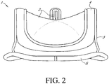
- Fig. 2 shows an example of one type of popular prosthetic replacement valve 1 that is a tissue-type bioprosthetic valve generally constructed with natural-tissue valve leaflets 2, made for example, from porcine tissue or bovine pericardium, or from synthetic or semisynthetic material, that are mounted on a surrounding valve stent structure 3.
- the shape and structure of the leaflets 2 is supported by a number of commissure posts 4 positioned circumferentially around the valve stent structure 3.
- a biocompatible cloth-covered suture or sewing ring 5 can also be provided on an inflow end of the stent structure 3 of the valve 1, to facilitate easier attachment to the native valve annulus.
- Such prosthetic valves function much like natural human heart valves, where the leaflets coapt against one another to effect the one-way flow of blood.
- a number of sutures may be involved in the attachment process, many of which may be pre-installed for providing a track on which the valve is advanced to and properly positioned at the implant site. Additional sutures may also be applied between the prosthetic valve and the heart walls after proper placement, to securely attach or hold the valve implant in place. Meanwhile, in some cases, the prosthetic valves are implanted through small access channels using one of various minimally invasive surgical procedures, where visibility at the implant site may be impeded or obstructed.
- commissure posts of the stent or frame, or other portions, of the prosthetic valve may be pointed distally and advanced on a blind side of the valve, thereby obstructing visibility of the posts or other portions during advancement and implantation.
- suture looping specifically refers to instances where a suture is inadvertently wrapped around one or more of the commissure post tips, where it can then migrate towards and damage the leaflets or interfere with proper leaflet coaptation or other valve operation when the sutures are tightened or secured, resulting in improper valve operation.
- such tangling may not be apparent to the practitioner at the time of implantation, and will only be revealed some time later when valve operation is observed to be improper or other complications arise in the patient, in which case, it may be necessary to initiate another procedure to repair or replace the prosthetic valve.
- a holder has a mechanism that urges the commissure posts of the prosthetic valve radially inwardly during delivery, such that the ends of the commissure posts are pointed inwards, to reduce the possibility of sutures catching against or looping around the commissure posts.
- such holders may not be amenable to minimally invasive surgical techniques as the holder and valve combination may have a high or large profile, for example with the entire holder system positioned outside the valve, or the holder may not pull in the commissures enough to reduce the valve profile.
- the system includes monofilament sutures that attach to both the holder and the commissures of the prosthetic valve, so that the sutures run over the outflow end of the valve between the ends of the commissures.
- a central post extends distally through the prosthetic valve between the leaflets and pushes against the sutures that run across the middle of the valve between the commissures, pushing the sutures distally and causing an angled tent-like or "umbrella" effect on the sutures.
- the pressure on the sutures deflects the commissures slightly inwardly, while also forming angled surfaces or tracks with the sutures that slope outwardly from the central post to the commissure posts. These angled surfaces deflect any other sutures that might otherwise be looped over a commissure or leaflet away from the prosthetic valve.
- this system may not be very amenable to a minimally invasive surgical approach. The system does not pull in the commissures enough to reduce the valve profile, and the central post of the holder adds to the overall height of the valve once deployed, hindering minimally invasive surgical procedures.
- Some holders incorporate various mechanisms and line connections, such that a number of additional steps must be taken by the practitioner to operate the holders correctly. Many of these holders have proven to be too complicated and/or prone to user error. For example, some holders may allow valves to be implanted without requiring that its mechanism be activated or deployed prior to delivery, for example, holders that allow delivery without deploying its mechanism to urge the commissure posts radially inward prior to insertion. Consequently, when practitioners use these holders improperly, suture looping still commonly occurs, while the implant process may also be further complicated by issues arising from user error.
- some holders may require the practitioner to manually adjust the tightening of the holder to the prosthetic valves. Tightening too little can make the holder ineffective to prevent suture looping, while over-tightening can risk breaking one or more sutures of the system or damaging the valve.
- a new replacement valve holder includes built-in mistake-proofing to ensure the anti-suture looping mechanism is engaged.
- the new replacement valve holder can be designed to enable surgeons to implant the valve through minimal incisions, such as in thoracotomy procedures.
- a valve and holder combination can be collapsible in at least one direction.
- holders and valves may not include a mechanism to actively collapse the valve into the reduced size configuration for delivery.
- an introducer according to other embodiments of the invention can be used with collapsible surgical valves and/or holders to introduce them into narrow surgical incisions, such as thoracotomies.
- the holders provide for new holder systems and methods of using the holder systems, which reduce or eliminate the occurrence of suture looping or other damage to the prosthetic valves during implantation, for example, for mitral valve replacement using minimally invasive procedures or other procedures. Operation of the holders is also simplified, whereby the valves are prevented from being implanted prior to deployment of the holders, for example, via a removable activator dial, thereby reducing or eliminating mistakes caused by user error.
- the dial cannot be removed until the system is activated, and while in place, the activator prevents the valve from being implanted.
- the holder includes a removable handle that cannot be connected to the system until the removable activator dial is removed.
- the holders also provide for integrated alignment features or other safety features, such that over-deployment or under-deployment of the holders is prevented.
- holders for prosthetic valve delivery reduce or eliminate occurrences of suture looping and/or other damage to the valves when the valves are implanted, while the mechanisms for deploying these features are integrated into the holders in a way that reduces or eliminates mistakes in use and deployment.
- a mitral valve holder and handle system uses a ratchet mechanism to pull in the commissures of the valve towards the center of the valve, thereby eliminating the risk of suture looping.
- the holder has mistake-proofing features that prevent the physician from implanting the valve without engaging the system.
- the holder system can allow implantation of the valve through a small or minimal incision.
- an introducer is provided to aid in implanting replacement valves through a minimal size incision, for example, by aiding in collapsing or otherwise reducing the profile of the valve and/or valve holder.
- the introducer can be used, for example, with mitral and/or aortic surgical valves.
- such an introducer can be relatively short and only long enough to pass the valve past a patient's ribs.
- the introducer can be relatively long and, for example, act as an atrial retractor, forming a channel all the way to the implant site in the case of a mitral valve.
- valve holders and introducers for assisting in the delivery and implantation of prosthetic heart valves, such as mitral heart valves, at an implant site.
- methods for preparing the prosthetic heart valves for such procedures are also methods for preparing the prosthetic heart valves for such procedures.
- Embodiments of the valve holders reduce occurrences of various complications that may arise during implantation, while remaining simple for end users to use. By providing these improved valve holders, damage to the prosthetic valves during surgical procedures can be reduced, and additional costs for extended or additional procedures and/or replacement valves can be avoided.
- valve holders disclosed herein are particularly useful for avoiding suture looping and other valve damage during advancement of the prosthetic valves to the implant sites, as well as during final suturing of the valves at the native valve annulus.
- commissure posts of the prosthetic valve point distally away from practitioners, and in the direction of valve advancement and may be more prone to suture looping or other entangling.
- valve holders according to embodiments of the invention can urge the commissure posts radially inwards toward a center of the valve to reduce or eliminate suture looping.
- the presented embodiments can also include features that prevent valve implantation until the valve holders are in the activated or deployed positions.
- the holders can also include alignment features that prevent over-deployment or under-deployment. In this fashion, the holders provide ease of use while minimizing or reducing user errors.
- the disclosed mitral valve holder and handle system is specifically designed to address shortcomings in previous valve holders.
- the disclosed system prevents clinicians from forgetting to deploy the system by means of a mistake-proof dial.
- the dial itself cannot be removed until the system is activated, and while the dial is in place, the dial prevents the valve from being implanted by: (1) physically making the system too bulky for implantation; (2) preventing the valve from being rotated or pivoted relative to the handle to a proper orientation for implantation; and (3) obstructing access to the sewing ring, thereby making placing sutures in the valve difficult.
- Figs. 3 to 5 show views of a valve holder 100 according to a first embodiment.
- Fig. 3 shows an exploded perspective view of the valve holder 100
- Fig. 4 shows a perspective view of the valve holder 100 in an assembled state
- Fig. 5 shows a cross-sectional view of the valve holder 100 in the assembled state.
- the valve holder 100 includes a body 102, a rotor 104, a swiveling delivery mount 106, a delivery handle 108, and an activator dial 110.
- a prosthetic heart valve can be attached to the body 102.
- the rotor 104 is positioned in a bore of the body 102 and is adjustable using the dial 110 to deploy or activate the valve holder 100 to adjust the prosthetic valve to a delivery position or configuration.
- the delivery mount 106 coupled to the delivery handle 108, is attached to the body 102 for delivering the valve to the implant site.
- the prosthetic valve can include a Nitinol wireform exhibiting a large amount of flexibility.
- the body 102 of the valve holder 100 is shown in greater detail in Figs. 6A and 6B .
- the body 102 includes a generally circular-shaped central hub 112 with a plurality of arms 114 extending from the central hub 112.
- the arms 114 serve as routing points for connecting commissure posts of the prosthetic valve to the valve holder 100 via sutures or other flexible material.
- the body 102 includes three arms 114, but can include more or fewer arms 114 in other embodiments depending on the prosthetic valve the valve holder is intended to hold.
- the number of arms 114 generally corresponds to the number of commissure posts on the prosthetic valve. When three arms 114 are included in the body 102, the arms 114 can extend from the body 102 at approximately 120 degrees relative to each other.
- Each of the arms 114 includes one or more through holes or bores 117 for routing the sutures.
- the sutures are used to deploy or activate the valve holder 100 and place the valve in a delivery position where the commissure posts are urged radially inwards toward a center of the valve to reduce or eliminate suture looping.
- the through holes 117 extend transverse through the arms 114.
- the through holes 117 route the sutures across the top of the arms 114 to a region below the arms 114 where the sutures can connect to tips of the commissure posts, for example, by passing the sutures over and/or through other portions of the valve. Multiple through holes 117 can be provided.
- Through holes 117a closer to the central hub 112, can be used to fasten or tie off an end of the sutures to the body 102, and to facilitate easier release of the valve from the valve holder 100.
- Through holes 117b located nearer free ends of the arms 114, are used to route and position the sutures for connection to the commissure posts.
- the sutures are routed through the arms 114 as follows. An end of the suture is fastened to the through hole 117a of the arms 114, for example, via a knot. The suture is then routed across a length of the arms 114 towards and through hole 117b. The free ends of the sutures are then in position to connect to the commissure posts of the valve.
- a different number of through holes 117 can be provided, and in some embodiments, only one through hole 117 is provided on each arm 114.
- a surface of the arms 114 includes a recess or slot 123.
- the sutures extend across the recesses 123 when extended between holes 117a and 117b, such that there is a clearance underneath the sutures in the region of the recesses 123 to provide space for cutting the sutures. Cutting the sutures at the region of the recess 123 will release the valve from the valve holder 102. If the valve is in the delivery position, cutting the sutures will also allow the commissures to spring back to a normal or unbiased geometry by releasing the commissure posts. Each of the sutures connected to the arms 114 are cut to release the valve.
- the sutures are routed from the tip of a commissure to the opposite cusp area of the body 102.
- a bore 116 is provided with an abutting surface 116a for receiving the rotor 104 therein.
- the abutting surface 116a serves as a stop for the rotor 104.
- the bore 116 extends into a bottom portion 118 of the body 102 that is circular-shaped and can have a smaller outer diameter than the central hub 112, for example, to provide clearance for a connected prosthetic valve.
- a through hole or bore 119 is positioned in the bottom portion 118 for coupling the rotor 104 to the body 102.
- the bottom portion 118 additionally includes through holes or bores 120 for routing the sutures from the tips of the commissure posts to inside of the bore 116 for attachment to the rotor 104.
- the number of through holes 120 generally corresponds to the number of arms 114.
- the through holes 120 can be co-linear with a direction of extension of the arms 114 and can be located along a periphery of the bottom portion 118.
- the through holes 120 can be located opposite to the position of the arms 114.
- the central hub 112 includes upwardly extending projections 121.
- the projections 121 have a profile that matches an inner profile of the handle 108.
- a tab 122 is provided for connecting the delivery mount 106 to the body 102.
- the arms 114b can be shaped to provide clearance for the delivery mount 106 and the delivery handle 108.
- an outer surface of the central hub 112 in a region adjacent the arms 114b can also have cutouts or other surface features to provide clearance for the delivery mount 106 and the delivery handle 108.
- central hub 112 and the bottom portion 118 are depicted as generally circular portions in the described embodiment, these portions can have different cross-sectional shapes in other embodiments.
- Fig. 7 shows a perspective view of the rotor 104 of the valve holder 100
- Fig. 8 shows a cross-sectional view of the rotor 104 attached to the body 102
- the rotor 104 is configured to be positioned inside of the bore 116 of the body 102 and is rotatable with respect to the body 102.
- the rotor 104 is connectable to the sutures for adjusting the prosthetic valve to the delivery position using the activator dial 110, as described further below.
- the rotor 104 includes a central portion 124 with a longitudinal axis and a plurality of outwardly extending flexible arms 125.
- the flexible arms 125 are resilient such that the arms can be deflected inwards towards the central portion 124 and then released, causing the arms 125 to spring back into a relaxed shape when no longer deflected.
- the rotor 104 is configured to be received in the bore 116 of the body 102.
- the rotor 104 includes a coupling mount 128 on the central portion 124 to rotatably couple to the hole 119 in the bottom portion 118 of the body 102.
- the connection between the coupling mount 128 and the hole 119 permits rotation, but restricts translational movement of the rotor 104 relative to the body 102.
- the coupling mount 128 is depicted as a protrusion that extends to a position below the body 102, and may be snap fit into hole 119.
- the coupling mount in other embodiments can be designed in any number of different ways, so long as the connection permits rotation and restricts translation of the rotor 104 relative to the body 102.
- the rotor 104 may be a monolithic part.
- the rotor 104 may include separate components to connect to the body 102, such as snap rings, pins, and/or nuts or other fasteners.
- the separate components may be positioned inside the body 102, for example, placed in a slot in the bottom portion 118 of the body 102 (not illustrated).
- the separate components may additionally or alternatively be positioned outside of the body 102, for example, surrounding a portion of the coupling mount 128.
- the coupling mount 128 can, for example, have the form of a hole, which rotatably connects to a protrusion in the bottom portion 118 of the body 102.
- the delivery mount 106 and/or the sutures secure the rotor within the body.
- end portions of the arms 125 have an engagement portion 126 in the form of teeth or pawls to engage a corresponding engagement portion 127 of an inner surface of the central hub 112, in the form of a plurality of notches or grooves.
- the teeth 126 of the rotor 104 engage the notches 127 of the body 102 to provide a one-way ratcheting mechanism that allows the rotor 104 to rotate in one direction relative to the body 102.
- the teeth 126 can have an asymmetric shape, such as a triangular shape, and the notches 127 can have a corresponding asymmetric cut out, such as a triangular cut-out, that permits the rotor 104 to rotate in only one direction relative to the orientation in Fig. 8 (e.g., clockwise as illustrated), but that prevents the rotor 104 from moving in a counter or opposite direction (e.g., counter-clockwise as illustrated).
- the teeth 126 slide along an angular surface of the notches 127 such that the flexible arms 125 are compressed inwards and the teeth 126 disengage from their currently engaged notches 127.
- the resilient flexible arms 125 spring back into their original shape and engage the subsequent notches 127. Due to the shape of the teeth 126 and the notches 127, the rotor 104 is prevented from rotating in an opposite direction and back into the previously engaged notches 127.
- the one-way ratcheting mechanism provides ease of use and prevents misuse of the rotor during operation.
- the engagement portions 126, 127 in the disclosed embodiments are depicted as having a triangular shape, the engagement portions 126, 127 in other embodiments can be designed in any number of different ways, so long as the connections allow for one-way rotational movement or pivoting of the rotor 104 relative to the body 102.
- the engagement portions of the arms 125 of the rotor 104 can have the form of notches or grooves and the engagement portions of the body 102 can have the form of teeth or pawls with a shape that corresponds to the engagement portions of the arms.
- the rotor 104 includes a central opening 129 for connection to the activator dial 110, as described in more detail below.
- the rotor 104 additionally includes one or more holes 130 projecting through a sidewall of the rotor 104 and into the central opening 129.
- the holes 130 provide attachment points for connecting end regions of the sutures to the rotor 104. After the sutures are routed through holes 120 in the bottom portion 118 of the body 102 as described above, end portions of the sutures can be connected to the rotor 104 via the holes 130.
- rotation of the rotor 104 will create tension in the suture lines and further cause the sutures to be pulled in the direction of the moving rotor 104.
- this pulling force activates or deploys the valve holder 100 to adjust the prosthetic value to a collapsed or delivery position by transferring the force onto the commissure posts of the prosthetic valve.
- the commissure posts are thereby radially urged inwards toward a center of the prosthetic valve.
- Fig. 9 shows a perspective view of the activator dial 110 of the valve holder 100.
- the dial 110 is used by an operator or user to rotate the rotor 104 and adjust the valve holder 100 to the deployed configuration.
- the activator dial 110 can be assembled with the valve holder 100 prior to use in a surgical procedure in an operating room.
- the activator dial 110 can be preassembled with the valve holder 100 during an assembly process by the manufacturer of the valve holder 100. Such an assembly step prior to use in surgical procedures can be done in order to aid in proper usage of the valve holder 100 and reduce the risk of inadvertent user errors.
- the dial 110 includes a central shaft 131 having a central axis, and an enlarged gripping portion 132 extending therefrom.
- the central shaft 131 is sized and configured to be received in the central opening 129 of the rotor 104.
- the central shaft or stem 131 includes alignment keyways 133 in the shape of longitudinally extending slots or recesses for coupling to the rotor 104.
- the rotor 104 includes corresponding alignment keys 134 in the shape of longitudinally extending protrusions positioned inside the central opening 129 to mate to alignment keys 133 of the activator dial 110. The mating of the alignment features 133, 134 enables the rotor 104 to rotate together with the dial 110 when the gripping portion 132 of the activator dial 110 is turned.
- the dial 110 can be turned either manually (for example, by the hands of an operator) or automatically via a motor or other means.
- three mating alignment features 133, 134 are respectively shown, the number of mating alignment features 133, 134 can be different in various embodiments. In one embodiment, for example, a single mating alignment feature 133, 134 can be used.
- Figs. 10 to 11 show views of the delivery mount 106 and delivery handle 108 of the holder 100.
- the delivery mount 106 and handle 108 are used to deliver the valve to the implant site and place the valve into a proper configuration for implantation.
- the delivery mount 106 is configured to be positioned on an upper surface of the body 102 (e.g., against central hub 112) and has a generally circular shape that corresponds to the shape of the body 102.
- the delivery mount On an outer edge of the delivery mount 106 opposite to the handle 108, the delivery mount includes one or more tabs 135 configured to be aligned with tab 122 of the body 102.
- the tabs 122, 135 are used to connect the delivery mount 106 to the body 102 via a single suture or other connector.
- the tabs 122, 135 can include aligned through holes or bores to route the suture.
- the delivery mount 106 and handle 108 can be quickly and easily removed from the body 102.
- the delivery mount 106 and handle 108 are used to move the holder 100 between a first configuration for delivery to the implant site, and a second configuration for final implantation.
- the handle 108 extends away from the body 102 in a direction opposite the tabs 122 ( Fig. 6A ), 135, such that the holder 100 and coupled valve have a low profile for insertion into the body.
- the holder 100 and coupled valve can have a slim cross-sectional profile that allows the assembly to be inserted past a patient's ribs.
- the delivery mount 106 while coupled to the body 102, is rotated or swiveled relative to the handle 108 such that the handle 108 extends away from the prosthetic valve, for example in a direction that is substantially coaxial or parallel to a central axis of the prosthetic valve.
- the prosthetic valve is in a configuration to be implanted in a heart of a human body ( see, e.g ., Figs. 12 and 13D ).
- the delivery mount 106 is rotatably coupled to the delivery handle 108 via fasteners 139 ( Fig. 3 ).
- the delivery mount 106 can rotate relative to the handle 108 along an axis that extends between the fasteners 139.
- the holder 100 includes a pivoting connector or clevis 138 connected to an upper surface of the delivery mount 106 on a side opposite to the handle 108.
- the pivoting connector 138 is connected to one end of a flexible tension cable, and the other end of the flexible tension cable is connected to a slide or rotation mechanism located on a grip of the handle 108 (not shown).
- the rotation of the valve relative to the handle 108 can therefore be controlled with the slide located on the handle 108 grip.
- the slide or rotation mechanism may include a thumb wheel or a lever.
- the slide or rotation mechanism can be actuated to place tension onto the tension cable, thereby pulling or pushing the pivoting connector 138 and rotating the delivery mount 106 and the connected valve from the first configuration to the second configuration. Meanwhile, as shown in Fig. 4 , when the activator dial 110 is connected to the valve holder 100, the dial 110 blocks the delivery mount 106 and handle 108 from entering into the second configuration.
- the dial 110 acts as a stop that prevents the holder 100 from moving into the second configuration until the holder 100 has been deployed by the dial 110 to adjust the valve to the collapsed or delivery position and the dial 110 has been removed from the holder 100.
- Safety of procedures using the holder 100 is thereby enhanced, helping to reduce or eliminate misuse of the holder 100 during operation.
- the delivery mount 106 additionally includes two alignment keyways 136a, 136b for use with the dial 110.
- the alignment keyways 136a, 136b provide ease of use and prevent misuse of the holder 100 during deployment.
- the alignment keyways 136a, 136b provide alignment for the activator dial 110 and act as stops that limit rotation of the dial 110 and the rotor 104 relative to body 102.
- the alignment keyways 136a, 136b are sized and configured to receive a key or protrusion 137 ( Fig. 9 ) of the activator dial 110 therethrough when the dial 110 is coupled to the rotor 104.
- the key 137 is positioned on the central shaft or stem 131 of the activator dial 110 to interact with the keyways 136a, 136b of the mount 106.
- the key 137 When positioning the central shaft 131 of the activator dial 110 in the central opening 129 of the rotor 104, the key 137 must be placed in keyway 136a in order to fully seat the activator dial 110 and to allow the activator dial 110 to rotate.
- the rotor 104 can only be rotated in one direction, for example, the clockwise direction, as described above.
- the activator dial 110 can be preassembled with the valve holder 100 prior to use in surgical procedures. To accomplish this, the central shaft 131 of the dial 110 is inserted into the rotor 104 with key 137 of the dial 110 inserted into keyway 136a of the delivery mount 106. The dial 110 and rotor 104 are then rotated relative to the body 102 such that teeth 126 and notches 127 become engaged, thus locking the dial 110 into the valve holder 100. In this configuration, the dial 110 is preassembled with the valve holder 100 for later use in surgical procedures. Because the engagement of the teeth 126 and notches 127 provide a one-way ratcheting mechanism, the activator dial 110 cannot be rotated counter-clockwise to be removed from through keyway 136.
- the engagement of the teeth 126 and notches 127 may be heard or felt by a "click" between the mating components as the rotor 104 is rotated.
- the teeth 126 and notches 127 can be identified as being engaged when the dial 110 and rotor 104 are rotated by at least one "click.”
- the key 137 is inserted in keyway 136a, either before or during surgical procedures.
- the dial 110 can be rotated clockwise, during surgical procedures, until the key 137 is lined up with keyway 136b, at which point no further rotation is possible and the dial 110 can be removed.
- the key 137 and keyway 136b do not align until the dial 110 is rotated to the point of fully engaging the system.
- the activator dial 110 cannot be rotated counter-clockwise by virtue of the one-way ratcheting mechanism of the rotor 104 and body 102.
- the activator dial 110 when the key 137 is inserted in keyway 136a, the activator dial 110 also cannot be rotated in the counter-clockwise direction. Lastly, a portion of the delivery mount 106 between the keyways 136a, 136b can be slightly thickened to form an additional stop for the key 137 to prevent over-rotation of the dial 110. Accordingly, the keyways 136a, 136b limit the amount of rotation of the activator dial 110 to less than one full turn.
- the keyways 136a, 136b enhance the safety of the holder 100 by eliminating over-tightening or under-tightening of the valve. Safety of procedures using the holder 100 is enhanced because the keyways 136, 136b can only be used in one way. Safety is also enhanced because the dial 110 can be preassembled with the holder 100 prior to use in surgical procedures. Meanwhile, once the dial 110 is assembled with the holder 100, the activator dial 110 can only be removed from the holder 100 when the key 137 reaches keyway 136b, requiring adjustment of the holder 100 into the second configuration before the dial can be removed.
- the holder 100 can have a low profile for implantation through minimally invasive incisions.
- the height of the holder with an attached valve is between about 12-20 mm when the holder 100 is in a deployed position and the commissures of the valve are pulled down and radially inward.
- the valve and holder combination may have a height of less than or equal to about 14 mm, so that the assembly would easily fit between most patient's ribs without spreading the ribs. This can be important, as spreading the ribs can result in more painful recovery for the patient.
- the height of typical valves when deployed is about 27 mm or greater, not including the holder.
- a pivot point of the holder 100 to adjust the holder 100 into the second configuration may be only between about 0 to 2 mm above an inflow edge of the valve. In one embodiment, the pivot point may be only about 1.27 mm above the inflow edge of the valve. Further, most of the ratchet mechanism of the holder 100 sits within the boundaries of the valve itself.
- a length of the handle 108 may be selected or optimized for use in minimally invasive procedures, such as thoracotomy procedures.
- the handle 108 may be made out of a malleable material, such as aluminum or Nitinol.
- Fig. 12 shows a perspective view of the valve holder 100 with the delivery mount 106 in the second configuration.
- a single suture can connect the body 102 to the delivery mount 106 and handle 108 via the tabs 122, 135.
- the handle 108 can be removed after cutting this single suture, which quickly releases the body 102 from the mount 106 and handle 108.
- the body 102 stays attached to the valve at this point, and the mechanism that pulls in the commissures remains activated.
- Figs. 13A to 13D show steps of using the holder 100 according to one embodiment.
- Fig. 13A shows a side view of the holder 100 and a prosthetic replacement valve to be implanted.
- the valve has not yet been coupled to the holder 100 and the activator dial 110 is also uncoupled from the holder 100.
- the valve can be attached to the holder 100 via three sutures that connect the commissure posts of the valve to the body 102 and the rotor 104.
- one end of each of the sutures is connected to respective arms 114 of the body 102 and passed through respective ones of the commissure posts.
- Opposite ends of each of the sutures are routed through respective holes 120 of the body 102 and holes 130 in the rotor 104.
- the activator dial 110 is coupled to the holder 100 to adjust the configuration of the holder 100.
- the central shaft 131 of the activator dial 110 is placed inside the central opening 129 of the rotor 104 with key 137 of the dial 110 aligned and inserted through keyway 136a of the delivery mount 106.
- keyways 136a, 136b which minimize or prevent misuse of the holder 100.
- the keyways 136a, 136b enable the dial 110 to be preassembled with the holder 100 prior to use in surgical procedures, as described above.
- the activator dial 110 will not rotate due to the one-way ratcheting mechanism of the body 102 and the rotor 104.
- the activator dial 110 can then be rotated in the clockwise direction, for example, for almost one full rotation until the key 137 is aligned with keyway 136b.
- the holder 100 is moved into a deployed state whereby the commissure posts of the valve are pulled down and inwards towards the center of the holder 100, as shown in Fig. 13C .
- the valve is ready for insertion into a body, but the activator dial 110 remains connected to the holder 100 and prevents insertion of the valve into a small or minimally invasive incision due to the dial's 110 large size.
- the dial 110 While the activator dial 110 is connected, the dial 110 also prevents the handle 108 from being rotated to move the holder 100 into the second configuration for final implantation.
- the activator dial 110 can then be removed from the holder 100 when key 137 is aligned with keyway 136b. Once the activator dial 110 is removed, the low profile of the combined valve and holder 100 allow the assembly to be inserted into a patent and moved past a patient's ribs. Once past the patient's ribs, the slide or rotation mechanism on the handle 108 can be actuated to rotate or pivot the holder 100 from the first configuration to the second configuration.
- Fig. 13D shows the holder 100 in the second configuration, with an outflow end of the valve facing away from the handle 108.
- the assembly is in position and ready to be implanted at a native heart valve of a patient.
- the operator can remove the delivery mount 106 and handle 108 from the holder 100 by cutting or untying the suture that connects tabs 122 and 135.
- the operator can remove the valve from the holder 100 by cutting or untying the three sutures that connect to commissure posts to the holder 100.
- the three sutures may be cut in the region of the recesses 123 of the arms 114 of the body 102.
- Figs. 14 to 16 show views of a valve holder 200 according to another embodiment.
- Fig. 14 shows an exploded perspective view of the valve holder 200
- Fig. 15 shows a perspective view of the valve holder 200 in an assembled state
- Fig. 16 shows a cross-sectional view of the valve holder 200 in the assembled state.
- the valve holder 200 of the second embodiment includes a body 202, a rotor 204, a delivery mount 206, a delivery handle 208, and an activator dial 210.
- the valve holder 200 of the second embodiment differs from the valve holder of the first embodiment in the design of the body 202, the delivery mount 206, and also in the connection of the valve to the body 102.
- the body 202 of this embodiment does not include the arms 114 of the first body, which were used for suture routing. Instead, the body 202 is shaped as a round or circular member with a suture mount 212 located at a periphery of the body 202 on a side opposite to the handle 208.
- the suture mount 212 is used as a single point to release the valve from the holder 200. For example, in embodiments where three sutures are used to attach to the commissure posts on the prosthetic valve ( see Fig. 17 ), each of the sutures is routed through the suture mount 212.
- the rotor 204 can be rotated by the activator dial 210 to deploy the prosthetic valve and cause the commissure posts to be urged down and radially inwards toward a center of the prosthetic valve.
- a single suture line can be used to connect the prosthetic valve to the holder 200 to simplify release of the valve.
- one end of the suture is connected to the rotor 204 via one or more holes 214 that extend through a sidewall of the rotor 204 and into a central opening 216 of the rotor 204.
- the suture is then routed from the hole 214, through a first commissure post, and then over the suture mount 212 of the body 202.
- the suture is then routed through a second commissure post and is again looped around the suture mount 212.
- the suture is routed through a third commissure post and again back to the suture mount 212, and is then tied off at the suture mount 212.
- the single suture connects all three commissure posts to the suture mount 212 and also to the rotor 204.
- the delivery mount 206 of the second embodiment differs from the first embodiment by the inclusion of a guard 218.
- the guard 218 is located at a periphery of the delivery mount 206 at a side opposite to the handle 208.
- the guard 218 is used to connect the delivery mount 206 to the body 202.
- the body 202 includes two through holes 220 ( Fig. 15 ) that extend vertically through the body 202. When the body 202 and delivery mount 206 are connected, the through holes 220 of the body 202 are adjacent to the guard 218.
- a single suture can be used to connect the body 202 to the delivery mount 206 via holes 220 and the guard 218.
- the guard 218 includes notches 222 for ease of routing the single suture. This suture can be cut or untied to quickly release the body 202 from the mount 206 and handle 208.
- the guard 218 provides an additional safety feature against inadvertent or premature release of the valve from the holder 200.
- the guard 218 is aligned with the suture mount 212 of the body 202, and is positioned over an upper surface of the suture mount 212 to cover the suture mount 212.
- the guard 218 blocks access to the suture connecting the valve to the holder 200, to prevent or make difficult any inadvertent or unintended cutting or breaking of the suture that would cause the holder 200 to be released from the valve while the delivery mount 206 remains coupled to the holder 200. Therefore, while the delivery mount 206 is connected to the body 202, a connected valve is restricted from being prematurely or inadvertently removed. When the delivery mount 206 is removed, the suture mount 212 is revealed and the suture can then be cut or untied to release the valve.
- Assembly of the holder 200 is as follows. First, the rotor 204 is received in the body 202 similar to the first embodiment. Next, one or more sutures are used to connect the holder 200 to the prosthetic valve. One end of the one or more sutures is connected to the rotor 204, and may be connected to a hole 214 extending through the sidewall of the rotor 204, as described above. The other end of the one or more sutures is routed through the commissure posts of the valve and connected to the suture mount 212 of the body 202. Next, the delivery mount 206 and handle 208 are coupled to the body 202. The delivery mount 206 is connected to the body 202 on a side opposite to the valve.
- the delivery mount 206 is positioned such that fasteners 224 and portions 226, 228 of the delivery mount 206 and handle 208, respectively, are received in slots 230 in the body 202.
- the delivery mount 206 is then coupled to the body 202 using one or more sutures via holes 220 in the body and the guard 218.
- the valve is in position to be deployed using the activator dial 210, similarly as discussed with respect to the first embodiment.
- a slide or rotation mechanism on the handle 208 can be actuated to rotate the valve from a first configuration for insertion into a patient and into a second configuration for final implantation, also similarly as described with respect to the first embodiment.
- the assembly sequence can be varied to achieve the same or similar assembled combinations.
- Figs. 18A to 20 show views of a valve holder 300 according to a third embodiment.
- Fig. 18A shows an exploded perspective view of the valve holder 300
- Fig. 18B shows a perspective view of an underside of a guide 306 of the valve holder 300
- Fig. 18C shows a perspective view of an activator dial 310 of the valve holder 300
- Fig. 19 shows a perspective view of the valve holder 300 in an assembled state
- Fig. 20 shows a cross-sectional view of the valve holder 300 in the assembled state.
- the valve holder 300 of the third embodiment allows the use of an inexpensive, reusable handle system, with a mitral valve holder that is activated or deployed to reduce or eliminate the occurrence of suture looping.
- the valve holder 300 of the third embodiment includes integrated alignment features or other safety features, such that over-deployment or under-deployment of the valve holder 300 is prevented or avoided.
- the valve holder 300 of the third embodiment differs from the valve holders 100, 200 of the first and second embodiments, for example, in that the third embodiment removes the swiveling functions of the delivery mounts 106, 206 and delivery handles 108, 208 of the first and second embodiments. Instead, the valve holder 300 can be attached and implanted via an inexpensive, reusable handle. Thereby, the valve holder 300 of the third embodiment can require fewer components than the first and second embodiments, a simpler assembly of the valve holder 300, and may provide a lower cost system.
- the valve holder 300 of the third embodiment includes a body 302, a rotor 304, a guide 306, a delivery latch 308, and an activator or activator dial 310. Similar to the first and second embodiments, a prosthetic heart valve can be attached to the body 302 of the valve holder 300 of the third embodiment ( see Figs. 21 , 22 , and 24 ).
- the rotor 304 is positioned in a bore of the body 302 and is adjustable using the dial 310 to deploy or activate the valve holder 300 for adjusting the prosthetic valve to a delivery position, as in the first and second embodiments. In the delivery position, the commissure posts of the prosthetic valve are urged downward and radially inwards toward a center of the valve to reduce or eliminate suture looping.
- the valve holder 300 includes an alignment keyway 336 for limiting rotation of the dial 310 and the rotor 304 relative to the body 302. This is to prevent over-deployment or under-deployment of the valve.
- the alignment keyway 336 is provided on a guide 306, which is attached to the body 302.
- the third embodiment does not include a swiveling delivery mount coupled to a delivery handle. Instead, the delivery latch 308 is attached to the body 302, and is used to connect to a delivery handle 305 ( see Figs. 23 and 24 ).
- the body 302 and rotor 304 of the third embodiment can be the same components or similar components as the body 202 and rotor 204 of the second embodiment.
- the body 302 and rotor 304 can be attached to the prosthetic valve using the same suture routing as described above with respect to the first and second embodiments. That is, three sutures can be used to attach the valve holder 300 to the commissure posts on the prosthetic valve as described above, and in some embodiments, a single suture line can be used to connect the prosthetic valve to the holder 300, also as described above.
- the body 302 includes a suture mount 312, which is the same or similar to the suture mount 212 of the second embodiment, and can provide a single access point to release the valve from the holder.
- the body 302, rotor 304, and dial 310 include the one-way ratcheting mechanism of the first and second embodiments to move the holder 300 into the deployed state by pulling the commissures of the prosthetic valve down and radially inward towards the center of the valve, and the description thereof will not be repeated,
- a central shaft or stem 331 of the dial 310 can be inserted into and connected to the rotor 304, such that turning the dial 310 rotates the rotor 304.
- holes in the rotor 304 e.g ., in sidewalls of the rotor 304) can provide attachment points for connecting and routing sutures.
- the central shaft 331 is hollow and has an internal cavity ( see Fig. 20 ), for example, to provide clearance for the sutures connected to inside of the rotor 304.
- the central shaft 331 can be inserted into the rotor 304 such that a bottom surface of the central shaft 331 is positioned adjacent or near a correspondence horizontal surface of the rotor 304.
- a lower portion of the central shaft 331 can include openings (e.g., notches) 309 to aid with suture routing (see Fig. 20 ).
- the openings 309 can extend through the walls of the central shaft 331 and exposes the holes in the rotor 304 used to connect to the sutures.
- the guide 306 of the third embodiment provides ease of use and prevents misuse of the holder 300 during deployment.
- the guide 306 is positioned above the rotor 304 such that the dial 310 must pass through a central opening 316 of the guide 306 before the dial 310 can be connected to the rotor 304.
- the guide 306 includes a keyway 336 and a wall 344, which provide alignment for the activator dial 310 via a key or protrusion 337 on the central shaft 331 of the dial 310 ( see Figs. 18A and 18C ).
- the keyway 336 and the wall 344 of the guide 306 act as a stop that limits rotation of the dial 310 and the rotor 304 relative to body 302.
- the key 337 of the dial 310 may be positioned on a flexible arm 339 of the central shaft 331.
- the flexible arm 339 may be spaced apart from the remainder of the central shaft 331 by gaps 341 on either side of the flexible arm 339 such that the flexible arm 339 is movable (e.g., bendable) relative to the remainder of the central shaft 331.
- the flexible arm 339 may be bent inwards relative to the remainder of the central shaft 331 and towards a cavity 343 of the dial 310.
- the flexible arm 339 may be resilient such that the flexible arm 339 may be bent by the application of a force and return to its original shape when the force is removed.
- the flexible arm 339 may be connected to an upper portion 345 of the dial 310.
- the dial 310 may be used in conjunction with the guide 306 to place the valve holder 300 in a deployed configuration as follows.
- the central shaft 331 of the dial 310 may be inserted into the central opening 316 of the guide 306 in an orientation such that the key 337 of the dial 310 is aligned with (e.g., rotationally aligned with) a portion of the guide 306.
- the key 337 may be rotationally aligned with a marker 342 of the guide 306.
- the key 337 of the dial 310 extends from dial 310 with a length that is greater than the diameter of the central opening 316 of the guide 306.
- a lower surface 337b of the key 337 will contact an upper surface 332 of the guide 306. Due to the flexibility of the flexible arm 339 of the dial 310, contact between the key 337 of the dial 310 and the upper surface 332 of the guide 306 causes the flexible arm 339 to bend inwards into the cavity 343 such that the key 337 may pass through the central opening of the guide 306.
- the lower surface 337b of the key 337 has an oblique or slanted shape ( e.g ., via a chamfer or fillet) relative to the upper surface 332 of the guide 306 to facilitate inward bending of the flexible arm 339 ( see Fig. 18C ).
- the flexible arm 339 returns to its original (e.g ., unbent) shape.
- An upper surface 337a of the key 337 has a flat shape that matches an underside surface 346 of the guide 306 to prevent or hinder the flexible arm 339 from bending once the key 337 passes the central opening 316 of the guide 306 (see Fig. 18C ). This is to retain the dial 310 in the guide 306 and prevent inadvertent or unintended removal of the dial 310 before deployment of the valve holder 300 is complete.
- the dial 310 may be rotated to cause the rotor 304 to rotate and deploy the valve, similarly described above with respect to the previous embodiments.
- the rotor 304 has a one-way ratcheting mechanism such that the dial 310 may only be rotated in one direction ( e.g ., clockwise relative to the orientation shown in Figs. 18A and 19 ), and the dial 310 is prevented from being rotating in an opposite direction.
- the underside of the guide 306 has a channel or groove 348 to facilitate rotation of the dial 310 relative to guide 306, which provides clearance for the key 337 of the dial 310 during rotation.
- the channel 348 has a shape that encompasses a partial circumference of the guide 306. That is, the channel 348 has a circumference that is less than 360 degrees such that the activator dial 310 is restricted to less than one full rotation in use.
- the guide 306 additional has a wall 344 to prevent over-deployment or over-tightening of the valve.
- the wall 334 acts as a stop against the key 337 to limit further rotation of the dial 310 when the key 337 is rotated in the channel 348.
- the wall 344 is adjacent the keyway 336 of the guide 306 such that when the dial 310 has been fully rotated in the channel 348, the dial 310 may be removed by removing the key 337 upwards through the keyway 336.
- the keyway 336 is sized to permit the key 337 of the dial 310 to fit therethrough. Upon removal of the dial 310, the valve holder 300 is in the fully deployed configuration. In addition, the keyway 336 and the one-way ratcheting mechanism prevent under-deployment of the valve. The dial 310 is prevented or hindered from being removed from the guide 306 until the key 337 is aligned with the keyway 336.
- the guide 306 is positioned in a bore 311 of the body 302, and is coaxial with a central axis of the body 302 and the rotor 304.
- the guide 306 is positioned in the body 302 such that an upper surface 322 of the guide 306 is flush with or recessed relative to an upper surface 324 of the body 302.
- the guide 306 includes a generally circular-shaped central hub 314 with the central opening 316, and a plurality of arms 317 extending from the central hub 314.
- the central hub 314 may have other shapes (e.g ., triangular, square, rectangular, irregularly shaped, or otherwise shaped).
- the central opening 316 of the guide 306 is sized to permit the central shaft 331 of the activator dial to extend therethrough in order for the dial 310 to engage with the rotor 304 for deployment of the valve holder 300.
- the guide 306 may include the marker 342 for identifying a connection orientation of the guide 306 relative to the body 302. The marker 342 may be aligned with one of the arms 317.
- the arms 317 of the guide 306 are used to connect the guide 306 to the body 302.
- the guide 306 includes three arms 317, but can include more or fewer arms 317 in other embodiments.
- the arms 317 can extend from the guide 306 at approximately 120 degrees relative to each other.
- the body 302 includes a plurality of openings or channels 320 to connect the guide 306 to the body 302.
- the openings 320 of the body 302 can extend through the body 302 from the upper surface of the body 302 to a lower surface 326 of the body 302.
- the arms 317 of the guide 306 contain connection elements 328 that are designed to connect to the body 302 when the arms 317 are inserted into the openings 320 of the body 302.
- the connection elements 328 of the guide 306 may include flat surfaces that mate with (e.g., abut) the lower surface 326 of the body 302.
- the arms 317 of the guide 306 may be resilient.
- the arms 317 may connect to the body 302 via a snap fit, press fit, or other connection.
- the guide 306 may be connected to the body 302 via a threaded engagement, and/or via pins or other fasteners or connection types.
- the delivery latch 308 is positioned on the guide 306, as shown in Fig. 20 , and is coaxial with the central axis of the body 302, the rotor 304, and the guide 306. In some embodiments, the delivery latch 308 is positioned on the upper surface 322 of the guide 306.
- the delivery latch 308 includes a central opening 330 that extends therethrough.
- the central opening 330 is designed to receive the dial 310, which as described above, is used to deploy or activate the valve holder 300 to adjust the prosthetic valve to the delivery position.
- the delivery latch 308 enables the stem of 331 of the dial 310 to be inserted into the latch 308, inserted into the guide 306, and connected to the rotor 304 for deploying the valve holder 300.
- the central opening 330 of the delivery latch 308 is designed to receive and connect to the delivery handle 305 for implantation of the prosthetic valve.
- the dial 310 while the dial 310 is positioned inside the delivery latch 308, the dial 310 prevents the handle 305 from being inserted into delivery latch 308. Thereby, the dial 310 acts as a feature that prevents implantation until the dial 310 has been removed from the valve holder 300. Safety of procedures using the valve holder 300 are thereby enhanced, helping to reduce or eliminate misuse of the holder 300 during operation.
- the central opening 330 of the delivery latch 308 is sized to permit the stem 331 and key 337 of the dial 310 to be inserted into the opening 330 and pass through the latch 308, so that the stem 331 engages the ratchet mechanism of the body 302 and rotor 304, and so that the key 337 of the dial 310 engages the guide 306 as described above.
- the central opening 330 includes a generally circular cross section.
- the central opening 330 includes a generally circular cross section with a notch 332 for guiding the key 337 of the dial 310 through the delivery latch 308 at a particular rotational orientation, as shown in Figs. 18 , 20 , and 21 .
- the central opening 330 of the delivery latch 308 includes an engagement portion 334 to mate with a corresponding engagement feature 338 of the handle 305.
- the handle 305 is configured to be inserted into the central opening 330 of the latch 308 and removably coupled to the latch 308 for implantation.
- the engagement portion 334 of the latch 308 and the engagement feature 338 of the handle 305 include mating threads 334a, 338a.
- the opening 330 of the latch 308 can include a non-threaded lead-in portion 340 located adjacent the threads 334a.
- the threads 338a of the handle 305 may first reach the non-threaded portion 340 of the latch 308 before reaching the threads 334a of the latch 308.
- the non-threaded portion 340 helps prevent potential cross threading and particle generation by ensuring axial alignment of the threads 338a of the handle 305 and threads 334a of the latch 308.
- the threads 338a of the handle 305 are provided on an end or tip of the handle 305.
- the threads 338a are made of a single piece and are crimped onto a nitinol shaft of the handle 305.
- an inner diameter between the threads 334a in the central opening 330 is sized such that the stem 331 and key 337 of the dial can pass therethrough.
- the notch 332 can extend through the threads 334a of the latch 308 for guiding the key 337 of the dial 310 through the delivery latch 308.
- the inner diameter between the threads 334a in the central opening 330 may be sized such that only the stem 331 of the dial 310 can pass through the threads, but not the key 337 (i.e., the key 337 fits through the notch 332 instead of the inner diameter between the threads 334a).
- the mating threads 334a, 338a have, for example, from a #10-24 thread to a 7/16"-14 thread, or an M4 ⁇ 0.7 thread to an M12 ⁇ 1.75 thread.
- the delivery latch 308 of the third embodiment includes a guard 318 that is the same or similar to the guard 218 of the delivery mount 206 of the second embodiment.
- the guard 318 is located at a periphery of the delivery latch 308.
- Opposite to the guard are protrusions 319 for engaging horizontal openings 321 on the body 302.
- the guard 318 and protrusions 319 are used to connect the delivery latch 308 to the body 302.
- the guard 318 allows a single suture to connect the delivery latch 308 to the body 302, as described above for the delivery mount 206. Further, the guard 318 provides an additional safety feature against inadvertent or premature release of the valve from the holder 300.
- the guard 318 is aligned with the suture mount 312 of the body 302, and is positioned over and covers the suture mount 312, thereby preventing or reducing inadvertent or unintended cutting or breaking of the sutures connecting the holder 300 to the valve.
- the suture mount 312 is revealed and the suture or sutures connecting the valve holder 300 to the valve can then be cut or untied to release the valve.
- Assembly of the holder 300 is as follows. First, the rotor 304 is received in the body 302 similar to the second embodiment. Next, the guide 306 is coupled to the body 302 in position over the rotor 304. In particular, the arms 317 of the guide 306 are inserted into the openings 320 of the body 302. Next, one or more sutures are used to connect the holder 300 to the prosthetic valve, as described above with respect to the second embodiment. In some embodiments, the holder 300 may be connected to the prosthetic valve before the guide 306 is coupled to the body 302. Next the delivery latch 308 is coupled to the body 302 in position over the guide 306.
- the delivery latch 308 is coupled to the body 302 using one or more sutures, the guard 318, and the protrusions 319.
- the valve holder 300 is in position to be deployed using the activator dial 310, similarly as discussed with respect to the first and second embodiments.
- the activator dial 310 is inserted into the central opening 330 of the latch 308, passed through the latch 308 and the guide 306, and connected to the rotor 304.
- the activator dial 308 is rotated to deploy the valve holder 300, and is then removed from the holder 300.
- the handle 305 can be inserted into and connected to the latch 308 for insertion and implantation of the attached valve into a patient.
- the assembly sequence can be varied to achieve the same or similar assembled combinations.
- valve holder various different features from the different embodiments discussed above can also be combined into a single modified valve holder.
- various other modifications or alternative configurations can also be made to the valve holder according to the above described embodiments.
- the presented embodiments also include an introducer which aids in delivering valve holders in minimally invasive surgical procedures.
- the introducer can be used with collapsible surgical valves to introduce the valves into a narrow surgical incision, such as a thoracotomy.
- the introducer can be used, for example, for delivering a prosthetic mitral valve to the mitral position.
- the introducer has a funnel-like shape for passing a collapsible heart valve from outside the body to inside the body through a narrow opening, such as the space between two ribs.
- an incision is introduced into the chest cavity through the chest wall.
- the incision is made between adjacent ribs to minimize cuts through bone, nerves, and muscle.
- the distance between the ribs, without spreading the ribs is from about 15 mm to about 20 mm.
- the incision can be longer as needed, for example, approximately 45 mm or greater.
- Collapsible valve holders can have a small size that is particularly suited to fit in the small gap between the ribs in thoracotomy procedures.
- Figs. 25 to 26 show views of an introducer 400 for introducing a valve and holder into a human body according to another embodiment.
- the introducer 400 provides a simple alternative approach for implanting collapsible heart valves connected to flexible holders through a minimal size incision, such as in a thoracotomy procedure. Due to the small gap between human ribs, the introducer 400 is used as an aid for inserting valves mounted on alternative flexible holders past the ribs and into the chest cavity during a thoracotomy or other minimally invasive procedures.
- the introducer 400 has a hollow, funnel-like shape for receiving flexible holders with mounted valves, with a central axis of the valves pointed in a direction of insertion, for example, with an outflow end of the valve pointed or directed towards the introducer 400.
- the introducer 400 has a first, proximal end 402, and a second, distal end 404.
- the distal end 404 of the introducer faces towards the incision, while the proximal end 402 faces away from the incision and towards the operator of the holder.
- the proximal end 402 has a circular cross-sectional shape corresponding to the circular shape of the prosthetic heart valves. In use, the proximal end 402 is located outside of the incision.
- the cross-section of the proximal end 402 is 45 mm in diameter.
- the distal end 404 has an oval cross-sectional shape corresponding to a size and shape of a surgical opening between ribs in a thoracotomy procedure.
- the major diameter of the cross section of the distal end 404 is about 45 mm in diameter and the minor diameter of the cross section is from about 15 mm to about 20 mm in diameter.
- the introducer 400 includes a smooth transition zone or region 406 connecting the ends 402, 404.
- the transition region 406 may have a smooth, continuous inner profile between the ends 402, 404, which is substantially free from corners.
- the introducer 400 can be made very inexpensively as a disposable item that is supplied with a valve.
- the introducer 400 can be made of or include polypropylene, or any other suitable material having a low coefficient of friction.
- the introducer 400 can be a molded part.
- the valve to be implanted can be made of a Nitinol wireform band exhibiting a large degree of elasticity. In one embodiment, the valve exhibits superelastic properties.
- the introducer 400 is first introduced into an incision in the chest cavity with the distal end 404 positioned between two ribs.
- the valve connected to a flexible holder, is inserted into the proximal end 402 of the introducer 400.
- the valve is then pushed towards the smaller, distal end 404 of the introducer 400, where the valve elastically deforms to squeeze through the smaller cross-sectional shape.
- the valve can take on the oval shape of the introducer or another generally collapsed shape as it is pushed through.
- the valve clears the distal end 404 of the introducer 400, the valve regains its undeformed shape (e.g., a circular shape). In this way, the deformation of the valve and holder is passive, being imposed or dictated by the shape of the introducer rather than by a mechanism on the holder itself.
- the advantage of this configuration is that the holder can be a very inexpensive molded component.
- a length of the introducer 400 is sufficient to introduce the valve into an internal surface of the chest wall past the rib cage.
- a length of the introducer from the proximal end 402 to the distal end 404 may be up to about 40 mm long. In other embodiments, a length of the introducer can be made longer.
- the distal end 404 could be extended many more centimeters so that it would extend, for example, into the left atrium of the heart, for a mitral valve replacement, to act as an atrial retractor.
- the proximal end 402 of the introducer 400 can remain positioned outside of the incision in the chest cavity. This would provide a tunnel from the outside of the body all the way to the site of implantation at the annulus.
- the introducer 400 can include various additional features, for example, a slit in a wall of the introducer 400 can be provided to give clearance for sutures passing through a side of the introducer during surgical procedures.
- lighting such as light emitting diodes ("LEDs") and/or at least one optical fiber, can be added to the introducer, along with a power supply, such as batteries, to power the lighting.
- LED lighting can be inexpensively added to the introducer with a built-in battery.
- the lighting can be particularly useful with the extended version of the introducer.
- the lighting can provide excellent illumination at the site of implantation and reduce the need for additional external lighting.
- a valve holder for holding and implanting a prosthetic heart valve comprising a frame and a plurality of flexible leaflets
- the valve holder comprises a body for holding the prosthetic heart valve, the body having a top surface, a bottom surface, and a central axis extending between the top and bottom surfaces; a rotor positioned in the body, wherein when the prosthetic heart valve is coupled to the body, the rotor is rotatable around the central axis of the body to adjust the prosthetic heart valve to a delivery position; and a latch having an opening couplable with a handle, and through which an activator is couplable to the rotor for rotating the rotor around the central axis of the body.
- valve holder according to the first embodiment further comprises the handle, wherein the opening of the latch comprises a threaded portion matable with a threaded portion of the handle.
- the threaded portion of the removable handle is at a tip of the handle.
- the opening of the latch comprises an unthreaded portion followed by the threaded portion such that when the handle is inserted into the latch, the tip passes through the unthreaded portion before the passing into the threaded portion.
- the rotor comprises an opening configured to receive the activator, and wherein the opening in the rotor and the opening in the latch are coaxial with the central axis of the body.
- valve holder according to any of the first to the fifth embodiments further comprises the handle and the activator, wherein when the handle is received in the opening in the latch, the handle blocks the activator from being connected to the latch.
- valve holder according to any of the first to the sixth embodiments further comprises the handle and the activator, wherein the activator is connectable to the rotor for rotating the rotor around the central axis of the body, and wherein when the activator is connected to the rotor, the activator blocks the handle from coupling to the latch.
- a system comprising the valve holder according to any of the first to the seventh embodiments and the prosthetic heart valve further comprises the activator, wherein the activator is connectable to the rotor at the top surface of the body and wherein the prosthetic heart valve is coupled to the bottom surface of the body.
- a system comprising the valve holder according to any of the first to the eighth embodiments and the prosthetic heart valve, the system further comprises the handle, wherein the prosthetic heart valve is wherein when the prosthetic heart valve is connected to the bottom surface of the body and the handle is connected to the latch, the top surface of the body faces the handle.
- a valve holder for holding and implanting a prosthetic heart valve comprises a frame and a plurality of flexible leaflets, the valve holder comprising a body for holding the prosthetic heart valve, the body having a top surface, a bottom surface, and a central axis extending between the top and bottom surfaces; a rotor positioned in the body, the rotor rotatable around the central axis of the body to adjust the prosthetic heart valve to a delivery position; and an activator connectable to the rotor for rotating the rotor around the central axis of the body; wherein a stop limits the rotation of the activator to less than one full turn around the central axis of the body, and wherein when the activator is connected to the rotor, a removable handle for implanting the prosthetic heart valve is prevented from connecting to the valve holder.
- the rotor rotatable around the central axis of the body in a first direction and not rotatable in a second direction opposite the first direction.
- valve holder according to the tenth or eleventh embodiment further comprises a guide coupled to the body, and a latch coupled to the body, wherein the stop is located on the guide, and wherein the latch is connectable to the removable handle.
- the top surface of the body is coupled to the guide and to the latch, and wherein the bottom surface of the body attachable to the prosthetic heart valve.
- the guide and the latch define openings permit the activator to access the rotor, and wherein the guide is located between the latch and the rotor.
- the opening in the latch is connectable to the removable handle.
- the opening of the latch comprises a threaded portion matable to a threaded portion of the removable handle.
- the threaded portion of the removable handle is at a tip of the handle.
- the activator comprises a key and the guide comprises a keyway having a shape corresponding to a shape of the key, the keyway permitting the key to pass therethrough when disconnecting the activator from the rotor.
- the activator is only disconnectable from the rotor when the key is rotationally aligned with the keyway.
- the rotor is rotatable around the central axis of the body in a first direction and not rotatable in a second direction opposite the first direction, and wherein when the key of the activator is aligned with the keyway, the activator is prevented from rotating in the first direction.
Landscapes
- Health & Medical Sciences (AREA)
- Cardiology (AREA)
- Life Sciences & Earth Sciences (AREA)
- Engineering & Computer Science (AREA)
- Biomedical Technology (AREA)
- Veterinary Medicine (AREA)
- Heart & Thoracic Surgery (AREA)
- Animal Behavior & Ethology (AREA)
- General Health & Medical Sciences (AREA)
- Public Health (AREA)
- Vascular Medicine (AREA)
- Transplantation (AREA)
- Oral & Maxillofacial Surgery (AREA)
- Surgery (AREA)
- Nuclear Medicine, Radiotherapy & Molecular Imaging (AREA)
- Medical Informatics (AREA)
- Molecular Biology (AREA)
- Prostheses (AREA)
Abstract
Description
- The present disclosure generally concerns medical devices, deployment mechanisms, and methods for deploying such medical devices. More specifically, the disclosure relates to surgical replacement of native heart valves that have malformations and/or dysfunctions. The present disclosure also relates to prosthetic heart valves, and specifically, prosthetic mitral valves that can be implanted through a minimal sized incision. Embodiments of the invention relate to holders for facilitating the implantation of bioprosthetic replacement heart valves at native heart valves, for example, for a mitral valve replacement procedure. Embodiments of the invention also relate to methods of using the holders to facilitate implantation of prosthetic heart valves.
- Referring first to
Fig. 1 , the human heart is generally separated into four pumping chambers, which pump blood through the body. Each chamber is provided with its own one-way exit valve. The left atrium receives oxygenated blood from the lungs and advances the oxygenated blood to the left ventricle through the mitral (or bicuspid) valve. The left ventricle collects the oxygenated blood from the left atrium and pushes it through the aortic valve to the aorta, where the oxygenated blood is then distributed to the rest of the body. Deoxygenated blood from the body is then collected at the right atrium and advanced to the right ventricle through the tricuspid valve. The right ventricle then advances the deoxygenated blood through the pulmonary valve and the pulmonary arteries to the lungs to again supply the blood with oxygen. - Each of the valves associated with the chambers of the heart are one-way valves that have leaflets to control the directional flow of the blood through the heart and to prevent backflow of the blood into other chambers or blood vessels that are upstream of the particular chamber. For example, as described above, the mitral valve controls the flow of oxygenated blood from the left atrium to the left ventricle, while preventing blood flow back into the left atrium. The valves are each supported by an annulus having a dense fibrous ring attached either directly or indirectly to the atrial or ventricular muscle fibers. When a valve become diseased or damaged, leakage or regurgitation may occur, where some of the blood travels back upstream through the diseased or damaged valve, and the efficiency and/or general functionality of the heart may be compromised.
- Various surgical techniques can be performed to repair or replace a diseased or damaged valve. In some valve replacement procedures, the leaflets of the diseased or damaged native valve are at least partially removed to prepare the valve annulus for receiving the prosthetic replacement valve.
Fig. 2 shows an example of one type of popular prosthetic replacement valve 1 that is a tissue-type bioprosthetic valve generally constructed with natural-tissue valve leaflets 2, made for example, from porcine tissue or bovine pericardium, or from synthetic or semisynthetic material, that are mounted on a surroundingvalve stent structure 3. The shape and structure of the leaflets 2 is supported by a number of commissure posts 4 positioned circumferentially around thevalve stent structure 3. In these valves, a biocompatible cloth-covered suture orsewing ring 5 can also be provided on an inflow end of thestent structure 3 of the valve 1, to facilitate easier attachment to the native valve annulus. Such prosthetic valves function much like natural human heart valves, where the leaflets coapt against one another to effect the one-way flow of blood. - When implanting a tissue type prosthetic valve as described above at a native valve annulus, a number of sutures may be involved in the attachment process, many of which may be pre-installed for providing a track on which the valve is advanced to and properly positioned at the implant site. Additional sutures may also be applied between the prosthetic valve and the heart walls after proper placement, to securely attach or hold the valve implant in place. Meanwhile, in some cases, the prosthetic valves are implanted through small access channels using one of various minimally invasive surgical procedures, where visibility at the implant site may be impeded or obstructed. In addition, depending on the direction of implantation, for example, with some mitral valve replacement procedures, commissure posts of the stent or frame, or other portions, of the prosthetic valve may be pointed distally and advanced on a blind side of the valve, thereby obstructing visibility of the posts or other portions during advancement and implantation.
- Each of the above factors may lead to tangling of the sutures with the valve prosthesis, most commonly with the commissure posts of the frame, since the commissure posts provide a protrusion on which the sutures can easily loop around and tangle. This type of entanglement of sutures with prosthetic valves is referred to as "suture looping," which specifically refers to instances where a suture is inadvertently wrapped around one or more of the commissure post tips, where it can then migrate towards and damage the leaflets or interfere with proper leaflet coaptation or other valve operation when the sutures are tightened or secured, resulting in improper valve operation. In some cases, such tangling may not be apparent to the practitioner at the time of implantation, and will only be revealed some time later when valve operation is observed to be improper or other complications arise in the patient, in which case, it may be necessary to initiate another procedure to repair or replace the prosthetic valve.
- In addition, many existing bioprosthetic valves are not amenable to implantation through a minimal size incision, such as in thoracotomy procedures. Such procedures can require a surgical valve and its holder to fit through incisions of approximately 15-20 mm in its narrowest direction or dimension.
- Attempts have been made to resolve the issue of suture looping, some of which involve holders, which hold the prosthetic valves during delivery of the valves to the native valve annulus. In one example, a holder has a mechanism that urges the commissure posts of the prosthetic valve radially inwardly during delivery, such that the ends of the commissure posts are pointed inwards, to reduce the possibility of sutures catching against or looping around the commissure posts. After the valve prosthesis is delivered to the implant site, the holder is removed thereby releasing and expanding the commissure posts to their original positions. However, such holders may not be amenable to minimally invasive surgical techniques as the holder and valve combination may have a high or large profile, for example with the entire holder system positioned outside the valve, or the holder may not pull in the commissures enough to reduce the valve profile.
- Meanwhile, Edwards Lifesciences has developed a valve holder system that can be used in mitral valve replacement procedures to protect the valve from suture looping during valve implantation. The system includes monofilament sutures that attach to both the holder and the commissures of the prosthetic valve, so that the sutures run over the outflow end of the valve between the ends of the commissures. When the holder is actuated, a central post extends distally through the prosthetic valve between the leaflets and pushes against the sutures that run across the middle of the valve between the commissures, pushing the sutures distally and causing an angled tent-like or "umbrella" effect on the sutures. The pressure on the sutures deflects the commissures slightly inwardly, while also forming angled surfaces or tracks with the sutures that slope outwardly from the central post to the commissure posts. These angled surfaces deflect any other sutures that might otherwise be looped over a commissure or leaflet away from the prosthetic valve. However, this system may not be very amenable to a minimally invasive surgical approach. The system does not pull in the commissures enough to reduce the valve profile, and the central post of the holder adds to the overall height of the valve once deployed, hindering minimally invasive surgical procedures.
- In addition to the above, many of the newer holder designs also incorporate many additional parts that must be assembled by the practitioner or other end user, which may also lead to additional complications. Some holders incorporate various mechanisms and line connections, such that a number of additional steps must be taken by the practitioner to operate the holders correctly. Many of these holders have proven to be too complicated and/or prone to user error. For example, some holders may allow valves to be implanted without requiring that its mechanism be activated or deployed prior to delivery, for example, holders that allow delivery without deploying its mechanism to urge the commissure posts radially inward prior to insertion. Consequently, when practitioners use these holders improperly, suture looping still commonly occurs, while the implant process may also be further complicated by issues arising from user error. Further, some holders may require the practitioner to manually adjust the tightening of the holder to the prosthetic valves. Tightening too little can make the holder ineffective to prevent suture looping, while over-tightening can risk breaking one or more sutures of the system or damaging the valve.
- Accordingly, a new replacement valve holder includes built-in mistake-proofing to ensure the anti-suture looping mechanism is engaged. In some embodiments, the new replacement valve holder can be designed to enable surgeons to implant the valve through minimal incisions, such as in thoracotomy procedures.
- In one example, to fit through a minimal size incision, such as through an about 15-20 mm incision, a valve and holder combination can be collapsible in at least one direction. However, such holders and valves may not include a mechanism to actively collapse the valve into the reduced size configuration for delivery. Accordingly, an introducer according to other embodiments of the invention can be used with collapsible surgical valves and/or holders to introduce them into narrow surgical incisions, such as thoracotomies.
- Features of the present disclosure provide for new holder systems and methods of using the holder systems, which reduce or eliminate the occurrence of suture looping or other damage to the prosthetic valves during implantation, for example, for mitral valve replacement using minimally invasive procedures or other procedures. Operation of the holders is also simplified, whereby the valves are prevented from being implanted prior to deployment of the holders, for example, via a removable activator dial, thereby reducing or eliminating mistakes caused by user error. According to embodiments, the dial cannot be removed until the system is activated, and while in place, the activator prevents the valve from being implanted. In some embodiments, the holder includes a removable handle that cannot be connected to the system until the removable activator dial is removed. The holders also provide for integrated alignment features or other safety features, such that over-deployment or under-deployment of the holders is prevented.
- According to embodiments of the invention, holders for prosthetic valve delivery reduce or eliminate occurrences of suture looping and/or other damage to the valves when the valves are implanted, while the mechanisms for deploying these features are integrated into the holders in a way that reduces or eliminates mistakes in use and deployment.
- In some embodiments, a mitral valve holder and handle system is provided that uses a ratchet mechanism to pull in the commissures of the valve towards the center of the valve, thereby eliminating the risk of suture looping. The holder has mistake-proofing features that prevent the physician from implanting the valve without engaging the system. In some embodiments, by flattening the profile of the valve, the holder system can allow implantation of the valve through a small or minimal incision. According to some embodiments, an introducer is provided to aid in implanting replacement valves through a minimal size incision, for example, by aiding in collapsing or otherwise reducing the profile of the valve and/or valve holder. The introducer can be used, for example, with mitral and/or aortic surgical valves. In some embodiments, such an introducer can be relatively short and only long enough to pass the valve past a patient's ribs. In other embodiments, the introducer can be relatively long and, for example, act as an atrial retractor, forming a channel all the way to the implant site in the case of a mitral valve.
- Further features and advantages of the invention will become apparent from the description of embodiments using the accompanying drawings. In the drawings:
-
Fig. 1 shows a schematic cross-sectional view of a human heart; -
Fig. 2 shows a schematic perspective view of an example of a prosthetic valve that can be used with embodiments of the invention; -
Fig. 3 shows an exploded perspective view of a valve holder for a prosthetic mitral valve according to a first embodiment of the invention; -
Fig. 4 shows a perspective view of the valve holder ofFig. 3 in an assembled state; -
Fig. 5 shows a cross-sectional view of the valve holder ofFigs. 3 and4 ; -
Figs. 6A and6B respectively show top and bottom views of a body of the valve holder ofFigs. 3 to 5 ; -
Fig. 7 shows a perspective view of a rotor of the valve holder ofFigs. 3 to 5 ; -
Fig. 8 shows a cross-sectional view of the rotor ofFig. 7 attached to the body ofFigs. 6A and6B ; -
Fig. 9 shows a perspective view of an activator of the valve holder ofFigs. 3 to 5 ; -
Fig. 10 shows a top view of a delivery mount of the valve holder ofFigs. 3 to 5 ; -
Fig. 11 shows a perspective view of the delivery mount ofFig. 10 attached to a handle; -
Fig. 12 shows a perspective view of the valve holder ofFigs. 3 to 5 in a deployed configuration with the activator removed and the delivery mount pivoted for insertion with sutures; -
Fig. 13A shows a side view of the valve holder ofFigs. 3 to 5 with a prosthetic valve in an unattached state; -
Fig. 13B shows a side view of the valve holder ofFigs. 3 to 5 in an undeployed configuration with a replacement valve attached thereto; -
Fig. 13C shows a side view of the valve holder ofFigs. 3 to 5 in a deployed configuration with a replacement valve attached thereto; -
Fig. 13D shows a side view of the valve holder ofFigs. 3 to 5 in a deployed configuration with the activator removed and the delivery mount pivoted for insertion, and with a replacement valve attached thereto; -
Fig. 14 shows an exploded perspective view of a valve holder for a prosthetic mitral valve according to a second embodiment of the invention; -
Fig. 15 shows a perspective view of the valve holder ofFig. 14 in an assembled state; -
Fig. 16 shows a cross-sectional view of the valve holder ofFigs. 14 and15 ; -
Fig. 17 shows a perspective view of the valve holder ofFigs. 14 to 16 in an assembled state with sutures; -
Fig. 18A shows an exploded perspective view of a valve holder for a prosthetic mitral valve according to a third embodiment of the invention; -
Fig. 18B shows a perspective view of an underside of a guide of the valve holder ofFig. 18A ; -
Fig. 18C shows a perspective view of an activator dial of the valve holder ofFig. 18A ; -
Fig. 19 shows a perspective view of the valve holder ofFig. 18A in an assembled state; -
Fig. 20 shows a cross-sectional view of the valve holder ofFigs. 18A and19 ; -
Fig. 21 shows a perspective view of the valve holder ofFigs. 18A to 20 in an assembled state with sutures; -
Fig. 22 shows a perspective view of the valve holder ofFigs. 18A to 21 in an assembled state with a latch removed; -
Fig. 23 shows a perspective view of a handle that can be used with the valve holder ofFigs. 18A to 22 ; -
Fig. 24 shows a perspective view of the handle ofFig. 23 attached to the valve holder ofFigs. 18A to 22 ; -
Fig. 25 shows a perspective view of an introducer for use with a valve holder; and -
Fig. 26 shows a front view of the introducer ofFig. 25 . - Disclosed herein are various tools, such as valve holders and introducers, for assisting in the delivery and implantation of prosthetic heart valves, such as mitral heart valves, at an implant site. Disclosed are also methods for preparing the prosthetic heart valves for such procedures. Embodiments of the valve holders reduce occurrences of various complications that may arise during implantation, while remaining simple for end users to use. By providing these improved valve holders, damage to the prosthetic valves during surgical procedures can be reduced, and additional costs for extended or additional procedures and/or replacement valves can be avoided.
- The valve holders disclosed herein are particularly useful for avoiding suture looping and other valve damage during advancement of the prosthetic valves to the implant sites, as well as during final suturing of the valves at the native valve annulus. In many existing mitral valve replacement procedures, commissure posts of the prosthetic valve point distally away from practitioners, and in the direction of valve advancement and may be more prone to suture looping or other entangling. For such procedures, valve holders according to embodiments of the invention can urge the commissure posts radially inwards toward a center of the valve to reduce or eliminate suture looping. The presented embodiments can also include features that prevent valve implantation until the valve holders are in the activated or deployed positions. The holders can also include alignment features that prevent over-deployment or under-deployment. In this fashion, the holders provide ease of use while minimizing or reducing user errors.
- The disclosed mitral valve holder and handle system is specifically designed to address shortcomings in previous valve holders. The disclosed system prevents clinicians from forgetting to deploy the system by means of a mistake-proof dial. The dial itself cannot be removed until the system is activated, and while the dial is in place, the dial prevents the valve from being implanted by: (1) physically making the system too bulky for implantation; (2) preventing the valve from being rotated or pivoted relative to the handle to a proper orientation for implantation; and (3) obstructing access to the sewing ring, thereby making placing sutures in the valve difficult.
-
Figs. 3 to 5 show views of avalve holder 100 according to a first embodiment.Fig. 3 shows an exploded perspective view of thevalve holder 100,Fig. 4 shows a perspective view of thevalve holder 100 in an assembled state, andFig. 5 shows a cross-sectional view of thevalve holder 100 in the assembled state. - The
valve holder 100 includes abody 102, arotor 104, a swivelingdelivery mount 106, adelivery handle 108, and anactivator dial 110. As described in more detail below, a prosthetic heart valve can be attached to thebody 102. Therotor 104 is positioned in a bore of thebody 102 and is adjustable using thedial 110 to deploy or activate thevalve holder 100 to adjust the prosthetic valve to a delivery position or configuration. Thedelivery mount 106, coupled to thedelivery handle 108, is attached to thebody 102 for delivering the valve to the implant site. The prosthetic valve can include a Nitinol wireform exhibiting a large amount of flexibility. - The
body 102 of thevalve holder 100 is shown in greater detail inFigs. 6A and6B . Thebody 102 includes a generally circular-shapedcentral hub 112 with a plurality ofarms 114 extending from thecentral hub 112. Thearms 114 serve as routing points for connecting commissure posts of the prosthetic valve to thevalve holder 100 via sutures or other flexible material. In the embodiment shown, thebody 102 includes threearms 114, but can include more orfewer arms 114 in other embodiments depending on the prosthetic valve the valve holder is intended to hold. The number ofarms 114 generally corresponds to the number of commissure posts on the prosthetic valve. When threearms 114 are included in thebody 102, thearms 114 can extend from thebody 102 at approximately 120 degrees relative to each other. - Each of the
arms 114 includes one or more through holes or bores 117 for routing the sutures. As will be described more fully below, the sutures are used to deploy or activate thevalve holder 100 and place the valve in a delivery position where the commissure posts are urged radially inwards toward a center of the valve to reduce or eliminate suture looping. The throughholes 117 extend transverse through thearms 114. The throughholes 117 route the sutures across the top of thearms 114 to a region below thearms 114 where the sutures can connect to tips of the commissure posts, for example, by passing the sutures over and/or through other portions of the valve. Multiple throughholes 117 can be provided. Throughholes 117a, closer to thecentral hub 112, can be used to fasten or tie off an end of the sutures to thebody 102, and to facilitate easier release of the valve from thevalve holder 100. Throughholes 117b, located nearer free ends of thearms 114, are used to route and position the sutures for connection to the commissure posts. In one embodiment, the sutures are routed through thearms 114 as follows. An end of the suture is fastened to the throughhole 117a of thearms 114, for example, via a knot. The suture is then routed across a length of thearms 114 towards and throughhole 117b. The free ends of the sutures are then in position to connect to the commissure posts of the valve. In other embodiments, a different number of throughholes 117 can be provided, and in some embodiments, only one throughhole 117 is provided on eacharm 114. In addition, a surface of thearms 114 includes a recess orslot 123. The sutures extend across therecesses 123 when extended betweenholes recesses 123 to provide space for cutting the sutures. Cutting the sutures at the region of therecess 123 will release the valve from thevalve holder 102. If the valve is in the delivery position, cutting the sutures will also allow the commissures to spring back to a normal or unbiased geometry by releasing the commissure posts. Each of the sutures connected to thearms 114 are cut to release the valve. - In order to have a good angle between the commissures of the valve, the sutures, and the
holder 100 for transmitting force to pull in the commissures, the sutures are routed from the tip of a commissure to the opposite cusp area of thebody 102. - In the
body 102, abore 116 is provided with an abutting surface 116a for receiving therotor 104 therein. The abutting surface 116a serves as a stop for therotor 104. Thebore 116 extends into abottom portion 118 of thebody 102 that is circular-shaped and can have a smaller outer diameter than thecentral hub 112, for example, to provide clearance for a connected prosthetic valve. A through hole or bore 119 is positioned in thebottom portion 118 for coupling therotor 104 to thebody 102. Thebottom portion 118 additionally includes through holes or bores 120 for routing the sutures from the tips of the commissure posts to inside of thebore 116 for attachment to therotor 104. The number of throughholes 120 generally corresponds to the number ofarms 114. The throughholes 120 can be co-linear with a direction of extension of thearms 114 and can be located along a periphery of thebottom portion 118. The throughholes 120 can be located opposite to the position of thearms 114. - As shown in
Figs. 3 to 5 , when thebody 102 is connected to thedelivery mount 106 and delivery handle 108, one of the arms 114a is aligned with thehandle 108, for example co-linear with thehandle 108, and two of thearms 114b extend away from thehandle 108. In a region adjacent a base of the arm 114a, thecentral hub 112 includes upwardly extendingprojections 121. Theprojections 121 have a profile that matches an inner profile of thehandle 108. On a side of thebody 102 opposite to the arm 114a, atab 122 is provided for connecting thedelivery mount 106 to thebody 102. Meanwhile, thearms 114b can be shaped to provide clearance for thedelivery mount 106 and thedelivery handle 108. Similarly, an outer surface of thecentral hub 112 in a region adjacent thearms 114b can also have cutouts or other surface features to provide clearance for thedelivery mount 106 and thedelivery handle 108. - While the
central hub 112 and thebottom portion 118 are depicted as generally circular portions in the described embodiment, these portions can have different cross-sectional shapes in other embodiments. -
Fig. 7 shows a perspective view of therotor 104 of thevalve holder 100, andFig. 8 shows a cross-sectional view of therotor 104 attached to thebody 102. Therotor 104 is configured to be positioned inside of thebore 116 of thebody 102 and is rotatable with respect to thebody 102. Therotor 104 is connectable to the sutures for adjusting the prosthetic valve to the delivery position using theactivator dial 110, as described further below. Therotor 104 includes acentral portion 124 with a longitudinal axis and a plurality of outwardly extendingflexible arms 125. Theflexible arms 125 are resilient such that the arms can be deflected inwards towards thecentral portion 124 and then released, causing thearms 125 to spring back into a relaxed shape when no longer deflected. - The
rotor 104 is configured to be received in thebore 116 of thebody 102. Therotor 104 includes acoupling mount 128 on thecentral portion 124 to rotatably couple to thehole 119 in thebottom portion 118 of thebody 102. When coupled, the connection between thecoupling mount 128 and thehole 119 permits rotation, but restricts translational movement of therotor 104 relative to thebody 102. Thecoupling mount 128 is depicted as a protrusion that extends to a position below thebody 102, and may be snap fit intohole 119. The coupling mount in other embodiments can be designed in any number of different ways, so long as the connection permits rotation and restricts translation of therotor 104 relative to thebody 102. In some embodiments, therotor 104 may be a monolithic part. In other embodiments, therotor 104 may include separate components to connect to thebody 102, such as snap rings, pins, and/or nuts or other fasteners. The separate components may be positioned inside thebody 102, for example, placed in a slot in thebottom portion 118 of the body 102 (not illustrated). The separate components may additionally or alternatively be positioned outside of thebody 102, for example, surrounding a portion of thecoupling mount 128. Meanwhile, in other embodiments, thecoupling mount 128 can, for example, have the form of a hole, which rotatably connects to a protrusion in thebottom portion 118 of thebody 102. In other embodiments, thedelivery mount 106 and/or the sutures secure the rotor within the body. - As shown in
Fig. 8 , end portions of thearms 125 have anengagement portion 126 in the form of teeth or pawls to engage acorresponding engagement portion 127 of an inner surface of thecentral hub 112, in the form of a plurality of notches or grooves. Theteeth 126 of therotor 104 engage thenotches 127 of thebody 102 to provide a one-way ratcheting mechanism that allows therotor 104 to rotate in one direction relative to thebody 102. Theteeth 126 can have an asymmetric shape, such as a triangular shape, and thenotches 127 can have a corresponding asymmetric cut out, such as a triangular cut-out, that permits therotor 104 to rotate in only one direction relative to the orientation inFig. 8 (e.g., clockwise as illustrated), but that prevents therotor 104 from moving in a counter or opposite direction (e.g., counter-clockwise as illustrated). When therotor 104 is rotated, theteeth 126 slide along an angular surface of thenotches 127 such that theflexible arms 125 are compressed inwards and theteeth 126 disengage from their currently engagednotches 127. When therotor 104 is rotated sufficiently that theteeth 126 approachsubsequent notches 127, the resilientflexible arms 125 spring back into their original shape and engage thesubsequent notches 127. Due to the shape of theteeth 126 and thenotches 127, therotor 104 is prevented from rotating in an opposite direction and back into the previously engagednotches 127. The one-way ratcheting mechanism provides ease of use and prevents misuse of the rotor during operation. Meanwhile, while theengagement portions engagement portions rotor 104 relative to thebody 102. Further, in some embodiments, the engagement portions of thearms 125 of therotor 104 can have the form of notches or grooves and the engagement portions of thebody 102 can have the form of teeth or pawls with a shape that corresponds to the engagement portions of the arms. - Further, the
rotor 104 includes acentral opening 129 for connection to theactivator dial 110, as described in more detail below. Therotor 104 additionally includes one ormore holes 130 projecting through a sidewall of therotor 104 and into thecentral opening 129. Theholes 130 provide attachment points for connecting end regions of the sutures to therotor 104. After the sutures are routed throughholes 120 in thebottom portion 118 of thebody 102 as described above, end portions of the sutures can be connected to therotor 104 via theholes 130. When the sutures are connected to therotor 104, rotation of therotor 104 will create tension in the suture lines and further cause the sutures to be pulled in the direction of the movingrotor 104. Because the sutures are connected to the commissure posts of the prosthetic valve, this pulling force activates or deploys thevalve holder 100 to adjust the prosthetic value to a collapsed or delivery position by transferring the force onto the commissure posts of the prosthetic valve. The commissure posts are thereby radially urged inwards toward a center of the prosthetic valve. -
Fig. 9 shows a perspective view of theactivator dial 110 of thevalve holder 100. Thedial 110 is used by an operator or user to rotate therotor 104 and adjust thevalve holder 100 to the deployed configuration. Theactivator dial 110 can be assembled with thevalve holder 100 prior to use in a surgical procedure in an operating room. In one embodiment, for example, theactivator dial 110 can be preassembled with thevalve holder 100 during an assembly process by the manufacturer of thevalve holder 100. Such an assembly step prior to use in surgical procedures can be done in order to aid in proper usage of thevalve holder 100 and reduce the risk of inadvertent user errors. - The
dial 110 includes acentral shaft 131 having a central axis, and an enlargedgripping portion 132 extending therefrom. Thecentral shaft 131 is sized and configured to be received in thecentral opening 129 of therotor 104. The central shaft or stem 131 includesalignment keyways 133 in the shape of longitudinally extending slots or recesses for coupling to therotor 104. Therotor 104 includescorresponding alignment keys 134 in the shape of longitudinally extending protrusions positioned inside thecentral opening 129 to mate toalignment keys 133 of theactivator dial 110. The mating of the alignment features 133, 134 enables therotor 104 to rotate together with thedial 110 when the grippingportion 132 of theactivator dial 110 is turned. In various embodiments, thedial 110 can be turned either manually (for example, by the hands of an operator) or automatically via a motor or other means. Meanwhile, while three mating alignment features 133, 134 are respectively shown, the number of mating alignment features 133, 134 can be different in various embodiments. In one embodiment, for example, a singlemating alignment feature -
Figs. 10 to 11 show views of thedelivery mount 106 and delivery handle 108 of theholder 100. Thedelivery mount 106 and handle 108 are used to deliver the valve to the implant site and place the valve into a proper configuration for implantation. Thedelivery mount 106 is configured to be positioned on an upper surface of the body 102 (e.g., against central hub 112) and has a generally circular shape that corresponds to the shape of thebody 102. On an outer edge of thedelivery mount 106 opposite to thehandle 108, the delivery mount includes one ormore tabs 135 configured to be aligned withtab 122 of thebody 102. Thetabs delivery mount 106 to thebody 102 via a single suture or other connector. To connect thetabs tabs delivery mount 106 to thebody 102, thedelivery mount 106 and handle 108 can be quickly and easily removed from thebody 102. - The
delivery mount 106 and handle 108 are used to move theholder 100 between a first configuration for delivery to the implant site, and a second configuration for final implantation. In the first configuration, thehandle 108 extends away from thebody 102 in a direction opposite the tabs 122 (Fig. 6A ), 135, such that theholder 100 and coupled valve have a low profile for insertion into the body. For example, in this first configuration, theholder 100 and coupled valve can have a slim cross-sectional profile that allows the assembly to be inserted past a patient's ribs. In the second configuration, thedelivery mount 106, while coupled to thebody 102, is rotated or swiveled relative to thehandle 108 such that thehandle 108 extends away from the prosthetic valve, for example in a direction that is substantially coaxial or parallel to a central axis of the prosthetic valve. In this second configuration, the prosthetic valve is in a configuration to be implanted in a heart of a human body (see, e.g.,Figs. 12 and13D ). - To rotate between the first and second configurations, the
delivery mount 106 is rotatably coupled to thedelivery handle 108 via fasteners 139 (Fig. 3 ). Thedelivery mount 106 can rotate relative to thehandle 108 along an axis that extends between thefasteners 139. To swivel thedelivery mount 106 relative to thehandle 108, theholder 100 includes a pivoting connector orclevis 138 connected to an upper surface of thedelivery mount 106 on a side opposite to thehandle 108. The pivotingconnector 138 is connected to one end of a flexible tension cable, and the other end of the flexible tension cable is connected to a slide or rotation mechanism located on a grip of the handle 108 (not shown). The rotation of the valve relative to thehandle 108 can therefore be controlled with the slide located on thehandle 108 grip. The slide or rotation mechanism may include a thumb wheel or a lever. The slide or rotation mechanism can be actuated to place tension onto the tension cable, thereby pulling or pushing the pivotingconnector 138 and rotating thedelivery mount 106 and the connected valve from the first configuration to the second configuration. Meanwhile, as shown inFig. 4 , when theactivator dial 110 is connected to thevalve holder 100, thedial 110 blocks thedelivery mount 106 and handle 108 from entering into the second configuration. As such, thedial 110 acts as a stop that prevents theholder 100 from moving into the second configuration until theholder 100 has been deployed by thedial 110 to adjust the valve to the collapsed or delivery position and thedial 110 has been removed from theholder 100. Safety of procedures using theholder 100 is thereby enhanced, helping to reduce or eliminate misuse of theholder 100 during operation. - The
delivery mount 106 additionally includes twoalignment keyways dial 110. Thealignment keyways holder 100 during deployment. Thealignment keyways activator dial 110 and act as stops that limit rotation of thedial 110 and therotor 104 relative tobody 102. To accomplish this, thealignment keyways Fig. 9 ) of theactivator dial 110 therethrough when thedial 110 is coupled to therotor 104. More specifically, the key 137 is positioned on the central shaft or stem 131 of theactivator dial 110 to interact with thekeyways mount 106. When positioning thecentral shaft 131 of theactivator dial 110 in thecentral opening 129 of therotor 104, the key 137 must be placed inkeyway 136a in order to fully seat theactivator dial 110 and to allow theactivator dial 110 to rotate. In use, therotor 104 can only be rotated in one direction, for example, the clockwise direction, as described above. - As described above, the
activator dial 110 can be preassembled with thevalve holder 100 prior to use in surgical procedures. To accomplish this, thecentral shaft 131 of thedial 110 is inserted into therotor 104 withkey 137 of thedial 110 inserted intokeyway 136a of thedelivery mount 106. Thedial 110 androtor 104 are then rotated relative to thebody 102 such thatteeth 126 andnotches 127 become engaged, thus locking thedial 110 into thevalve holder 100. In this configuration, thedial 110 is preassembled with thevalve holder 100 for later use in surgical procedures. Because the engagement of theteeth 126 andnotches 127 provide a one-way ratcheting mechanism, theactivator dial 110 cannot be rotated counter-clockwise to be removed from through keyway 136. The engagement of theteeth 126 andnotches 127 may be heard or felt by a "click" between the mating components as therotor 104 is rotated. Theteeth 126 andnotches 127 can be identified as being engaged when thedial 110 androtor 104 are rotated by at least one "click." - In use, the key 137 is inserted in
keyway 136a, either before or during surgical procedures. Following insertion of the key 137 into keyway 136, thedial 110 can be rotated clockwise, during surgical procedures, until the key 137 is lined up withkeyway 136b, at which point no further rotation is possible and thedial 110 can be removed. The key 137 andkeyway 136b do not align until thedial 110 is rotated to the point of fully engaging the system. At the position ofkeyway 136b, theactivator dial 110 cannot be rotated counter-clockwise by virtue of the one-way ratcheting mechanism of therotor 104 andbody 102. Further, when the key 137 is inserted inkeyway 136a, theactivator dial 110 also cannot be rotated in the counter-clockwise direction. Lastly, a portion of thedelivery mount 106 between thekeyways dial 110. Accordingly, thekeyways activator dial 110 to less than one full turn. - The
keyways holder 100 by eliminating over-tightening or under-tightening of the valve. Safety of procedures using theholder 100 is enhanced because thekeyways 136, 136b can only be used in one way. Safety is also enhanced because thedial 110 can be preassembled with theholder 100 prior to use in surgical procedures. Meanwhile, once thedial 110 is assembled with theholder 100, theactivator dial 110 can only be removed from theholder 100 when the key 137reaches keyway 136b, requiring adjustment of theholder 100 into the second configuration before the dial can be removed. - When the
activator dial 110 is removed, theholder 100 can have a low profile for implantation through minimally invasive incisions. In one embodiment, the height of the holder with an attached valve is between about 12-20 mm when theholder 100 is in a deployed position and the commissures of the valve are pulled down and radially inward. In some embodiments, the valve and holder combination may have a height of less than or equal to about 14 mm, so that the assembly would easily fit between most patient's ribs without spreading the ribs. This can be important, as spreading the ribs can result in more painful recovery for the patient. By comparison, the height of typical valves when deployed is about 27 mm or greater, not including the holder. In addition, a pivot point of theholder 100 to adjust theholder 100 into the second configuration may be only between about 0 to 2 mm above an inflow edge of the valve. In one embodiment, the pivot point may be only about 1.27 mm above the inflow edge of the valve. Further, most of the ratchet mechanism of theholder 100 sits within the boundaries of the valve itself. - A length of the
handle 108 may be selected or optimized for use in minimally invasive procedures, such as thoracotomy procedures. Thehandle 108 may be made out of a malleable material, such as aluminum or Nitinol. -
Fig. 12 shows a perspective view of thevalve holder 100 with thedelivery mount 106 in the second configuration. A single suture can connect thebody 102 to thedelivery mount 106 and handle 108 via thetabs handle 108 can be removed after cutting this single suture, which quickly releases thebody 102 from themount 106 and handle 108. Thebody 102 stays attached to the valve at this point, and the mechanism that pulls in the commissures remains activated. -
Figs. 13A to 13D show steps of using theholder 100 according to one embodiment.Fig. 13A shows a side view of theholder 100 and a prosthetic replacement valve to be implanted. The valve has not yet been coupled to theholder 100 and theactivator dial 110 is also uncoupled from theholder 100. In this configuration, the valve can be attached to theholder 100 via three sutures that connect the commissure posts of the valve to thebody 102 and therotor 104. As described above, one end of each of the sutures is connected torespective arms 114 of thebody 102 and passed through respective ones of the commissure posts. Opposite ends of each of the sutures are routed throughrespective holes 120 of thebody 102 andholes 130 in therotor 104. When initially connected, theholder 100 is in an undeployed state and the commissure posts of the valve are in an expanded or unbiased position, as shown inFig. 13B . - In the state shown in
Fig. 13B , theactivator dial 110 is coupled to theholder 100 to adjust the configuration of theholder 100. To couple thedial 110 to theholder 100, thecentral shaft 131 of theactivator dial 110 is placed inside thecentral opening 129 of therotor 104 withkey 137 of thedial 110 aligned and inserted throughkeyway 136a of thedelivery mount 106. Proper use of thedial 110 is facilitated by thekeyways holder 100. For example, thekeyways dial 110 to be preassembled with theholder 100 prior to use in surgical procedures, as described above. In another example, should the dial 110 with the key 137 be aligned and inserted intokeyway 136b, instead of keyway 136a, theactivator dial 110 will not rotate due to the one-way ratcheting mechanism of thebody 102 and therotor 104. - From the configuration shown in
Fig. 13B , theactivator dial 110 can then be rotated in the clockwise direction, for example, for almost one full rotation until the key 137 is aligned withkeyway 136b. As theactivator dial 110 is rotated, theholder 100 is moved into a deployed state whereby the commissure posts of the valve are pulled down and inwards towards the center of theholder 100, as shown inFig. 13C . In this state, the valve is ready for insertion into a body, but theactivator dial 110 remains connected to theholder 100 and prevents insertion of the valve into a small or minimally invasive incision due to the dial's 110 large size. While theactivator dial 110 is connected, thedial 110 also prevents thehandle 108 from being rotated to move theholder 100 into the second configuration for final implantation. - From the configuration shown in
Fig. 13C , theactivator dial 110 can then be removed from theholder 100 when key 137 is aligned withkeyway 136b. Once theactivator dial 110 is removed, the low profile of the combined valve andholder 100 allow the assembly to be inserted into a patent and moved past a patient's ribs. Once past the patient's ribs, the slide or rotation mechanism on thehandle 108 can be actuated to rotate or pivot theholder 100 from the first configuration to the second configuration. -
Fig. 13D shows theholder 100 in the second configuration, with an outflow end of the valve facing away from thehandle 108. In this configuration, the assembly is in position and ready to be implanted at a native heart valve of a patient. In a later step during use of theholder 100, the operator can remove thedelivery mount 106 and handle 108 from theholder 100 by cutting or untying the suture that connectstabs holder 100, the operator can remove the valve from theholder 100 by cutting or untying the three sutures that connect to commissure posts to theholder 100. The three sutures may be cut in the region of therecesses 123 of thearms 114 of thebody 102. -
Figs. 14 to 16 show views of avalve holder 200 according to another embodiment.Fig. 14 shows an exploded perspective view of thevalve holder 200,Fig. 15 shows a perspective view of thevalve holder 200 in an assembled state, andFig. 16 shows a cross-sectional view of thevalve holder 200 in the assembled state. Similar to the first embodiment, thevalve holder 200 of the second embodiment includes abody 202, arotor 204, adelivery mount 206, adelivery handle 208, and anactivator dial 210. Thevalve holder 200 of the second embodiment differs from the valve holder of the first embodiment in the design of thebody 202, thedelivery mount 206, and also in the connection of the valve to thebody 102. - The
body 202 of this embodiment does not include thearms 114 of the first body, which were used for suture routing. Instead, thebody 202 is shaped as a round or circular member with asuture mount 212 located at a periphery of thebody 202 on a side opposite to thehandle 208. Thesuture mount 212 is used as a single point to release the valve from theholder 200. For example, in embodiments where three sutures are used to attach to the commissure posts on the prosthetic valve (seeFig. 17 ), each of the sutures is routed through thesuture mount 212. Similar to the first embodiment, therotor 204 can be rotated by theactivator dial 210 to deploy the prosthetic valve and cause the commissure posts to be urged down and radially inwards toward a center of the prosthetic valve. - In addition, in one embodiment, a single suture line can be used to connect the prosthetic valve to the
holder 200 to simplify release of the valve. In such an embodiment, one end of the suture is connected to therotor 204 via one ormore holes 214 that extend through a sidewall of therotor 204 and into acentral opening 216 of therotor 204. The suture is then routed from thehole 214, through a first commissure post, and then over thesuture mount 212 of thebody 202. The suture is then routed through a second commissure post and is again looped around thesuture mount 212. Finally, the suture is routed through a third commissure post and again back to thesuture mount 212, and is then tied off at thesuture mount 212. When finished, the single suture connects all three commissure posts to thesuture mount 212 and also to therotor 204. - Meanwhile, the
delivery mount 206 of the second embodiment differs from the first embodiment by the inclusion of aguard 218. Theguard 218 is located at a periphery of thedelivery mount 206 at a side opposite to thehandle 208. Theguard 218 is used to connect thedelivery mount 206 to thebody 202. Thebody 202 includes two through holes 220 (Fig. 15 ) that extend vertically through thebody 202. When thebody 202 anddelivery mount 206 are connected, the throughholes 220 of thebody 202 are adjacent to theguard 218. A single suture can be used to connect thebody 202 to thedelivery mount 206 viaholes 220 and theguard 218. To that end, theguard 218 includesnotches 222 for ease of routing the single suture. This suture can be cut or untied to quickly release thebody 202 from themount 206 and handle 208. - Further, the
guard 218 provides an additional safety feature against inadvertent or premature release of the valve from theholder 200. When thedelivery mount 206 is coupled to theholder 200, theguard 218 is aligned with thesuture mount 212 of thebody 202, and is positioned over an upper surface of thesuture mount 212 to cover thesuture mount 212. Theguard 218 blocks access to the suture connecting the valve to theholder 200, to prevent or make difficult any inadvertent or unintended cutting or breaking of the suture that would cause theholder 200 to be released from the valve while thedelivery mount 206 remains coupled to theholder 200. Therefore, while thedelivery mount 206 is connected to thebody 202, a connected valve is restricted from being prematurely or inadvertently removed. When thedelivery mount 206 is removed, thesuture mount 212 is revealed and the suture can then be cut or untied to release the valve. - Assembly of the
holder 200 according to one embodiment is as follows. First, therotor 204 is received in thebody 202 similar to the first embodiment. Next, one or more sutures are used to connect theholder 200 to the prosthetic valve. One end of the one or more sutures is connected to therotor 204, and may be connected to ahole 214 extending through the sidewall of therotor 204, as described above. The other end of the one or more sutures is routed through the commissure posts of the valve and connected to thesuture mount 212 of thebody 202. Next, thedelivery mount 206 and handle 208 are coupled to thebody 202. Thedelivery mount 206 is connected to thebody 202 on a side opposite to the valve. Thedelivery mount 206 is positioned such thatfasteners 224 andportions delivery mount 206 and handle 208, respectively, are received inslots 230 in thebody 202. Thedelivery mount 206 is then coupled to thebody 202 using one or more sutures viaholes 220 in the body and theguard 218. When all of the described features are assembled, the valve is in position to be deployed using theactivator dial 210, similarly as discussed with respect to the first embodiment. Additionally, once theactivator dial 210 is removed, a slide or rotation mechanism on thehandle 208 can be actuated to rotate the valve from a first configuration for insertion into a patient and into a second configuration for final implantation, also similarly as described with respect to the first embodiment. In other embodiments, the assembly sequence can be varied to achieve the same or similar assembled combinations. -
Figs. 18A to 20 show views of avalve holder 300 according to a third embodiment.Fig. 18A shows an exploded perspective view of thevalve holder 300,Fig. 18B shows a perspective view of an underside of aguide 306 of thevalve holder 300,Fig. 18C shows a perspective view of anactivator dial 310 of thevalve holder 300,Fig. 19 shows a perspective view of thevalve holder 300 in an assembled state, andFig. 20 shows a cross-sectional view of thevalve holder 300 in the assembled state. - The
valve holder 300 of the third embodiment allows the use of an inexpensive, reusable handle system, with a mitral valve holder that is activated or deployed to reduce or eliminate the occurrence of suture looping. As in the first and second embodiments, thevalve holder 300 of the third embodiment includes integrated alignment features or other safety features, such that over-deployment or under-deployment of thevalve holder 300 is prevented or avoided. Thevalve holder 300 of the third embodiment differs from thevalve holders valve holder 300 can be attached and implanted via an inexpensive, reusable handle. Thereby, thevalve holder 300 of the third embodiment can require fewer components than the first and second embodiments, a simpler assembly of thevalve holder 300, and may provide a lower cost system. - The
valve holder 300 of the third embodiment includes abody 302, arotor 304, aguide 306, adelivery latch 308, and an activator oractivator dial 310. Similar to the first and second embodiments, a prosthetic heart valve can be attached to thebody 302 of thevalve holder 300 of the third embodiment (seeFigs. 21 ,22 , and24 ). Therotor 304 is positioned in a bore of thebody 302 and is adjustable using thedial 310 to deploy or activate thevalve holder 300 for adjusting the prosthetic valve to a delivery position, as in the first and second embodiments. In the delivery position, the commissure posts of the prosthetic valve are urged downward and radially inwards toward a center of the valve to reduce or eliminate suture looping. As described in further detail below, thevalve holder 300 includes analignment keyway 336 for limiting rotation of thedial 310 and therotor 304 relative to thebody 302. This is to prevent over-deployment or under-deployment of the valve. Thealignment keyway 336 is provided on aguide 306, which is attached to thebody 302. Unlike the first and second embodiments, the third embodiment does not include a swiveling delivery mount coupled to a delivery handle. Instead, thedelivery latch 308 is attached to thebody 302, and is used to connect to a delivery handle 305 (seeFigs. 23 and24 ). - The
body 302 androtor 304 of the third embodiment can be the same components or similar components as thebody 202 androtor 204 of the second embodiment. In particular, thebody 302 androtor 304 can be attached to the prosthetic valve using the same suture routing as described above with respect to the first and second embodiments. That is, three sutures can be used to attach thevalve holder 300 to the commissure posts on the prosthetic valve as described above, and in some embodiments, a single suture line can be used to connect the prosthetic valve to theholder 300, also as described above. In addition, thebody 302 includes asuture mount 312, which is the same or similar to thesuture mount 212 of the second embodiment, and can provide a single access point to release the valve from the holder. - Meanwhile, the
body 302,rotor 304, and dial 310 include the one-way ratcheting mechanism of the first and second embodiments to move theholder 300 into the deployed state by pulling the commissures of the prosthetic valve down and radially inward towards the center of the valve, and the description thereof will not be repeated, As described above with respect to the first and second embodiments, a central shaft or stem 331 of thedial 310 can be inserted into and connected to therotor 304, such that turning thedial 310 rotates therotor 304. Also as described above with respect to the first and second embodiments, holes in the rotor 304 (e.g., in sidewalls of the rotor 304) can provide attachment points for connecting and routing sutures. In some embodiments, thecentral shaft 331 is hollow and has an internal cavity (seeFig. 20 ), for example, to provide clearance for the sutures connected to inside of therotor 304. Thecentral shaft 331 can be inserted into therotor 304 such that a bottom surface of thecentral shaft 331 is positioned adjacent or near a correspondence horizontal surface of therotor 304. In such embodiments, a lower portion of thecentral shaft 331 can include openings (e.g., notches) 309 to aid with suture routing (seeFig. 20 ). Theopenings 309 can extend through the walls of thecentral shaft 331 and exposes the holes in therotor 304 used to connect to the sutures. - Similar to the delivery mounts 106, 206 of the first and second embodiments, the
guide 306 of the third embodiment provides ease of use and prevents misuse of theholder 300 during deployment. As shown inFig. 20 , theguide 306 is positioned above therotor 304 such that thedial 310 must pass through acentral opening 316 of theguide 306 before thedial 310 can be connected to therotor 304. Theguide 306 includes akeyway 336 and awall 344, which provide alignment for theactivator dial 310 via a key orprotrusion 337 on thecentral shaft 331 of the dial 310 (seeFigs. 18A and18C ). Thekeyway 336 and thewall 344 of theguide 306 act as a stop that limits rotation of thedial 310 and therotor 304 relative tobody 302. - As shown in
Fig. 18C ., in some embodiments, the key 337 of thedial 310 may be positioned on aflexible arm 339 of thecentral shaft 331. Theflexible arm 339 may be spaced apart from the remainder of thecentral shaft 331 bygaps 341 on either side of theflexible arm 339 such that theflexible arm 339 is movable (e.g., bendable) relative to the remainder of thecentral shaft 331. Theflexible arm 339 may be bent inwards relative to the remainder of thecentral shaft 331 and towards acavity 343 of thedial 310. Theflexible arm 339 may be resilient such that theflexible arm 339 may be bent by the application of a force and return to its original shape when the force is removed. Theflexible arm 339 may be connected to anupper portion 345 of thedial 310. - In some embodiments, the
dial 310 may be used in conjunction with theguide 306 to place thevalve holder 300 in a deployed configuration as follows. Thecentral shaft 331 of thedial 310 may be inserted into thecentral opening 316 of theguide 306 in an orientation such that the key 337 of thedial 310 is aligned with (e.g., rotationally aligned with) a portion of theguide 306. In some embodiments, the key 337 may be rotationally aligned with amarker 342 of theguide 306. The key 337 of thedial 310 extends fromdial 310 with a length that is greater than the diameter of thecentral opening 316 of theguide 306. As such, upon insertion of thecentral shaft 331 into theguide 306, alower surface 337b of the key 337 will contact anupper surface 332 of theguide 306. Due to the flexibility of theflexible arm 339 of thedial 310, contact between the key 337 of thedial 310 and theupper surface 332 of theguide 306 causes theflexible arm 339 to bend inwards into thecavity 343 such that the key 337 may pass through the central opening of theguide 306. Thelower surface 337b of the key 337 has an oblique or slanted shape (e.g., via a chamfer or fillet) relative to theupper surface 332 of theguide 306 to facilitate inward bending of the flexible arm 339 (seeFig. 18C ). Once the key 337 passes thecentral opening 316 of theguide 306, theflexible arm 339 returns to its original (e.g., unbent) shape. Anupper surface 337a of the key 337 has a flat shape that matches anunderside surface 346 of theguide 306 to prevent or hinder theflexible arm 339 from bending once the key 337 passes thecentral opening 316 of the guide 306 (seeFig. 18C ). This is to retain thedial 310 in theguide 306 and prevent inadvertent or unintended removal of thedial 310 before deployment of thevalve holder 300 is complete. - Once the key 337 passes the
central opening 316 of theguide 306 and thedial 310 is connected to therotor 304, thedial 310 may be rotated to cause therotor 304 to rotate and deploy the valve, similarly described above with respect to the previous embodiments. Therotor 304 has a one-way ratcheting mechanism such that thedial 310 may only be rotated in one direction (e.g., clockwise relative to the orientation shown inFigs. 18A and19 ), and thedial 310 is prevented from being rotating in an opposite direction. The underside of theguide 306 has a channel or groove 348 to facilitate rotation of thedial 310 relative to guide 306, which provides clearance for the key 337 of thedial 310 during rotation. Thechannel 348 has a shape that encompasses a partial circumference of theguide 306. That is, thechannel 348 has a circumference that is less than 360 degrees such that theactivator dial 310 is restricted to less than one full rotation in use. Theguide 306 additional has awall 344 to prevent over-deployment or over-tightening of the valve. The wall 334 acts as a stop against the key 337 to limit further rotation of thedial 310 when the key 337 is rotated in thechannel 348. Thewall 344 is adjacent thekeyway 336 of theguide 306 such that when thedial 310 has been fully rotated in thechannel 348, thedial 310 may be removed by removing the key 337 upwards through thekeyway 336. Thekeyway 336 is sized to permit the key 337 of thedial 310 to fit therethrough. Upon removal of thedial 310, thevalve holder 300 is in the fully deployed configuration. In addition, thekeyway 336 and the one-way ratcheting mechanism prevent under-deployment of the valve. Thedial 310 is prevented or hindered from being removed from theguide 306 until the key 337 is aligned with thekeyway 336. - As shown in
Fig. 20 , theguide 306 is positioned in abore 311 of thebody 302, and is coaxial with a central axis of thebody 302 and therotor 304. In some embodiments, theguide 306 is positioned in thebody 302 such that anupper surface 322 of theguide 306 is flush with or recessed relative to anupper surface 324 of thebody 302. Theguide 306 includes a generally circular-shaped central hub 314 with thecentral opening 316, and a plurality ofarms 317 extending from the central hub 314. In some embodiments, the central hub 314 may have other shapes (e.g., triangular, square, rectangular, irregularly shaped, or otherwise shaped). As described above, thecentral opening 316 of theguide 306 is sized to permit thecentral shaft 331 of the activator dial to extend therethrough in order for thedial 310 to engage with therotor 304 for deployment of thevalve holder 300. In some embodiments, theguide 306 may include themarker 342 for identifying a connection orientation of theguide 306 relative to thebody 302. Themarker 342 may be aligned with one of thearms 317. - The
arms 317 of theguide 306 are used to connect theguide 306 to thebody 302. In the embodiment shown inFig. 20 , theguide 306 includes threearms 317, but can include more orfewer arms 317 in other embodiments. When threearms 317 are included in theguide 306, thearms 317 can extend from theguide 306 at approximately 120 degrees relative to each other. Thebody 302 includes a plurality of openings orchannels 320 to connect theguide 306 to thebody 302. Theopenings 320 of thebody 302 can extend through thebody 302 from the upper surface of thebody 302 to alower surface 326 of thebody 302. Thearms 317 of theguide 306 containconnection elements 328 that are designed to connect to thebody 302 when thearms 317 are inserted into theopenings 320 of thebody 302. In some embodiments, theconnection elements 328 of theguide 306 may include flat surfaces that mate with (e.g., abut) thelower surface 326 of thebody 302. Thearms 317 of theguide 306 may be resilient. In some embodiments, thearms 317 may connect to thebody 302 via a snap fit, press fit, or other connection. In some embodiments, theguide 306 may be connected to thebody 302 via a threaded engagement, and/or via pins or other fasteners or connection types. - The
delivery latch 308 is positioned on theguide 306, as shown inFig. 20 , and is coaxial with the central axis of thebody 302, therotor 304, and theguide 306. In some embodiments, thedelivery latch 308 is positioned on theupper surface 322 of theguide 306. - The
delivery latch 308 includes acentral opening 330 that extends therethrough. Thecentral opening 330 is designed to receive thedial 310, which as described above, is used to deploy or activate thevalve holder 300 to adjust the prosthetic valve to the delivery position. In particular, thedelivery latch 308 enables the stem of 331 of thedial 310 to be inserted into thelatch 308, inserted into theguide 306, and connected to therotor 304 for deploying thevalve holder 300. When thedial 310 is removed from thelatch 308, thecentral opening 330 of thedelivery latch 308 is designed to receive and connect to thedelivery handle 305 for implantation of the prosthetic valve. However, while thedial 310 is positioned inside thedelivery latch 308, thedial 310 prevents thehandle 305 from being inserted intodelivery latch 308. Thereby, thedial 310 acts as a feature that prevents implantation until thedial 310 has been removed from thevalve holder 300. Safety of procedures using thevalve holder 300 are thereby enhanced, helping to reduce or eliminate misuse of theholder 300 during operation. - The
central opening 330 of thedelivery latch 308 is sized to permit thestem 331 andkey 337 of thedial 310 to be inserted into theopening 330 and pass through thelatch 308, so that thestem 331 engages the ratchet mechanism of thebody 302 androtor 304, and so that the key 337 of thedial 310 engages theguide 306 as described above. In some embodiments, thecentral opening 330 includes a generally circular cross section. In some embodiments, thecentral opening 330 includes a generally circular cross section with anotch 332 for guiding the key 337 of thedial 310 through thedelivery latch 308 at a particular rotational orientation, as shown inFigs. 18 ,20 , and21 . - The
central opening 330 of thedelivery latch 308 includes an engagement portion 334 to mate with a corresponding engagement feature 338 of thehandle 305. Thehandle 305 is configured to be inserted into thecentral opening 330 of thelatch 308 and removably coupled to thelatch 308 for implantation. In some embodiments, the engagement portion 334 of thelatch 308 and the engagement feature 338 of thehandle 305 include mating threads 334a, 338a. In such an embodiment, theopening 330 of thelatch 308 can include a non-threaded lead-inportion 340 located adjacent the threads 334a. When thehandle 305 is inserted into thecentral opening 330 of thelatch 308, the threads 338a of thehandle 305 may first reach thenon-threaded portion 340 of thelatch 308 before reaching the threads 334a of thelatch 308. Thenon-threaded portion 340 helps prevent potential cross threading and particle generation by ensuring axial alignment of the threads 338a of thehandle 305 and threads 334a of thelatch 308. The threads 338a of thehandle 305 are provided on an end or tip of thehandle 305. In some embodiments, the threads 338a are made of a single piece and are crimped onto a nitinol shaft of thehandle 305. - In some embodiments, an inner diameter between the threads 334a in the
central opening 330 is sized such that thestem 331 andkey 337 of the dial can pass therethrough. In embodiments containing thenotch 332 in thecentral opening 330, thenotch 332 can extend through the threads 334a of thelatch 308 for guiding the key 337 of thedial 310 through thedelivery latch 308. In such embodiments, the inner diameter between the threads 334a in thecentral opening 330 may be sized such that only thestem 331 of thedial 310 can pass through the threads, but not the key 337 (i.e., the key 337 fits through thenotch 332 instead of the inner diameter between the threads 334a). This allows for a diameter of thestem 331 of thedial 310 to be smaller and the threads 338a of thehandle 305 to be smaller. In some embodiments, the mating threads 334a, 338a have, for example, from a #10-24 thread to a 7/16"-14 thread, or an M4 × 0.7 thread to an M12 × 1.75 thread. - Meanwhile, the
delivery latch 308 of the third embodiment includes aguard 318 that is the same or similar to theguard 218 of thedelivery mount 206 of the second embodiment. Theguard 318 is located at a periphery of thedelivery latch 308. Opposite to the guard areprotrusions 319 for engaginghorizontal openings 321 on thebody 302. Theguard 318 andprotrusions 319 are used to connect thedelivery latch 308 to thebody 302. Theguard 318 allows a single suture to connect thedelivery latch 308 to thebody 302, as described above for thedelivery mount 206. Further, theguard 318 provides an additional safety feature against inadvertent or premature release of the valve from theholder 300. When thedelivery latch 308 is coupled to theholder 300, theguard 318 is aligned with thesuture mount 312 of thebody 302, and is positioned over and covers thesuture mount 312, thereby preventing or reducing inadvertent or unintended cutting or breaking of the sutures connecting theholder 300 to the valve. When thedelivery latch 308 is removed, thesuture mount 312 is revealed and the suture or sutures connecting thevalve holder 300 to the valve can then be cut or untied to release the valve. - Assembly of the
holder 300 according to some embodiments is as follows. First, therotor 304 is received in thebody 302 similar to the second embodiment. Next, theguide 306 is coupled to thebody 302 in position over therotor 304. In particular, thearms 317 of theguide 306 are inserted into theopenings 320 of thebody 302. Next, one or more sutures are used to connect theholder 300 to the prosthetic valve, as described above with respect to the second embodiment. In some embodiments, theholder 300 may be connected to the prosthetic valve before theguide 306 is coupled to thebody 302. Next thedelivery latch 308 is coupled to thebody 302 in position over theguide 306. Thedelivery latch 308 is coupled to thebody 302 using one or more sutures, theguard 318, and theprotrusions 319. When all of the described features are assembled, thevalve holder 300 is in position to be deployed using theactivator dial 310, similarly as discussed with respect to the first and second embodiments. In particular, theactivator dial 310 is inserted into thecentral opening 330 of thelatch 308, passed through thelatch 308 and theguide 306, and connected to therotor 304. Theactivator dial 308 is rotated to deploy thevalve holder 300, and is then removed from theholder 300. Once theactivator dial 310 is removed, thehandle 305 can be inserted into and connected to thelatch 308 for insertion and implantation of the attached valve into a patient. In other embodiments, the assembly sequence can be varied to achieve the same or similar assembled combinations. - Meanwhile, various different features from the different embodiments discussed above can also be combined into a single modified valve holder. In addition, various other modifications or alternative configurations can also be made to the valve holder according to the above described embodiments.
- The presented embodiments also include an introducer which aids in delivering valve holders in minimally invasive surgical procedures. The introducer can be used with collapsible surgical valves to introduce the valves into a narrow surgical incision, such as a thoracotomy. The introducer can be used, for example, for delivering a prosthetic mitral valve to the mitral position. The introducer has a funnel-like shape for passing a collapsible heart valve from outside the body to inside the body through a narrow opening, such as the space between two ribs. In thoracotomy procedures, an incision is introduced into the chest cavity through the chest wall. In intercostal approaches, the incision is made between adjacent ribs to minimize cuts through bone, nerves, and muscle. In a typical thoracotomy procedure, the distance between the ribs, without spreading the ribs, is from about 15 mm to about 20 mm. Parallel to the ribs, the incision can be longer as needed, for example, approximately 45 mm or greater. Collapsible valve holders can have a small size that is particularly suited to fit in the small gap between the ribs in thoracotomy procedures.
-
Figs. 25 to 26 show views of anintroducer 400 for introducing a valve and holder into a human body according to another embodiment. Theintroducer 400 provides a simple alternative approach for implanting collapsible heart valves connected to flexible holders through a minimal size incision, such as in a thoracotomy procedure. Due to the small gap between human ribs, theintroducer 400 is used as an aid for inserting valves mounted on alternative flexible holders past the ribs and into the chest cavity during a thoracotomy or other minimally invasive procedures. - The
introducer 400 has a hollow, funnel-like shape for receiving flexible holders with mounted valves, with a central axis of the valves pointed in a direction of insertion, for example, with an outflow end of the valve pointed or directed towards theintroducer 400. Theintroducer 400 has a first,proximal end 402, and a second,distal end 404. Thedistal end 404 of the introducer faces towards the incision, while theproximal end 402 faces away from the incision and towards the operator of the holder. Theproximal end 402 has a circular cross-sectional shape corresponding to the circular shape of the prosthetic heart valves. In use, theproximal end 402 is located outside of the incision. In one embodiment, the cross-section of theproximal end 402 is 45 mm in diameter. Thedistal end 404 has an oval cross-sectional shape corresponding to a size and shape of a surgical opening between ribs in a thoracotomy procedure. In one embodiment, the major diameter of the cross section of thedistal end 404 is about 45 mm in diameter and the minor diameter of the cross section is from about 15 mm to about 20 mm in diameter. Between the proximal anddistal ends introducer 400 includes a smooth transition zone orregion 406 connecting theends transition region 406 may have a smooth, continuous inner profile between theends - The
introducer 400 can be made very inexpensively as a disposable item that is supplied with a valve. For example, theintroducer 400 can be made of or include polypropylene, or any other suitable material having a low coefficient of friction. Theintroducer 400 can be a molded part. Meanwhile, the valve to be implanted can be made of a Nitinol wireform band exhibiting a large degree of elasticity. In one embodiment, the valve exhibits superelastic properties. - In use, the
introducer 400 is first introduced into an incision in the chest cavity with thedistal end 404 positioned between two ribs. The valve, connected to a flexible holder, is inserted into theproximal end 402 of theintroducer 400. The valve is then pushed towards the smaller,distal end 404 of theintroducer 400, where the valve elastically deforms to squeeze through the smaller cross-sectional shape. The valve can take on the oval shape of the introducer or another generally collapsed shape as it is pushed through. Once the valve clears thedistal end 404 of theintroducer 400, the valve regains its undeformed shape (e.g., a circular shape). In this way, the deformation of the valve and holder is passive, being imposed or dictated by the shape of the introducer rather than by a mechanism on the holder itself. The advantage of this configuration is that the holder can be a very inexpensive molded component. - In one embodiment, a length of the
introducer 400 is sufficient to introduce the valve into an internal surface of the chest wall past the rib cage. In such an embodiment, a length of the introducer from theproximal end 402 to thedistal end 404 may be up to about 40 mm long. In other embodiments, a length of the introducer can be made longer. In one embodiment, thedistal end 404 could be extended many more centimeters so that it would extend, for example, into the left atrium of the heart, for a mitral valve replacement, to act as an atrial retractor. Meanwhile, theproximal end 402 of theintroducer 400 can remain positioned outside of the incision in the chest cavity. This would provide a tunnel from the outside of the body all the way to the site of implantation at the annulus. - In alternative embodiments, the
introducer 400 can include various additional features, for example, a slit in a wall of theintroducer 400 can be provided to give clearance for sutures passing through a side of the introducer during surgical procedures. In addition, lighting, such as light emitting diodes ("LEDs") and/or at least one optical fiber, can be added to the introducer, along with a power supply, such as batteries, to power the lighting. LED lighting can be inexpensively added to the introducer with a built-in battery. The lighting can be particularly useful with the extended version of the introducer. The lighting can provide excellent illumination at the site of implantation and reduce the need for additional external lighting. - For purposes of this description, certain aspects, advantages, and novel features of the embodiments of this disclosure are described herein. The disclosed methods, apparatus, and systems should not be construed as being limiting in any way. Instead, the present disclosure is directed toward all novel and nonobvious features and aspects of the various disclosed embodiments, alone and in various combinations and sub-combinations with one another. The methods, apparatus, and systems are not limited to any specific aspect or feature or combination thereof, nor do the disclosed embodiments require that any one or more specific advantages be present or problems be solved.
- Although the operations of some of the disclosed embodiments are described in a particular, sequential order for convenient presentation, it should be understood that this manner of description encompasses rearrangement, unless a particular ordering is required by specific language set forth below. For example, operations described sequentially can in some cases be rearranged or performed concurrently. Moreover, for the sake of simplicity, the attached figures may not show the various ways in which the disclosed methods can be used in conjunction with other methods. Additionally, the description sometimes uses terms like "provide" or "achieve" to describe the disclosed methods. These terms are high-level abstractions of the actual operations that are performed. The actual operations that correspond to these terms can vary depending on the particular implementation and are readily discernible by one of ordinary skill in the art.
- In view of the many possible embodiments to which the principles of the disclosure can be applied, it should be recognized that the illustrated embodiments are only preferred examples and should not be taken as limiting the scope of the disclosure. Rather, the scope of the disclosure is defined by the following claims.
- The application further comprises the following embodiments:
In a first embodiment, a valve holder for holding and implanting a prosthetic heart valve comprising a frame and a plurality of flexible leaflets, the valve holder comprises a body for holding the prosthetic heart valve, the body having a top surface, a bottom surface, and a central axis extending between the top and bottom surfaces; a rotor positioned in the body, wherein when the prosthetic heart valve is coupled to the body, the rotor is rotatable around the central axis of the body to adjust the prosthetic heart valve to a delivery position; and a latch having an opening couplable with a handle, and through which an activator is couplable to the rotor for rotating the rotor around the central axis of the body. - In a second embodiment, the valve holder according to the first embodiment further comprises the handle, wherein the opening of the latch comprises a threaded portion matable with a threaded portion of the handle.
- In a third embodiment of the valve holder according to the second embodiment, the threaded portion of the removable handle is at a tip of the handle.
- In a fourth embodiment of the valve holder according to the third embodiment, the opening of the latch comprises an unthreaded portion followed by the threaded portion such that when the handle is inserted into the latch, the tip passes through the unthreaded portion before the passing into the threaded portion.
- In a fifth embodiment of the valve holder according to any of the first to the fourth embodiments, the rotor comprises an opening configured to receive the activator, and wherein the opening in the rotor and the opening in the latch are coaxial with the central axis of the body.
- In a sixth embodiment, the valve holder according to any of the first to the fifth embodiments further comprises the handle and the activator, wherein when the handle is received in the opening in the latch, the handle blocks the activator from being connected to the latch.
- In a seventh embodiment, the valve holder according to any of the first to the sixth embodiments further comprises the handle and the activator, wherein the activator is connectable to the rotor for rotating the rotor around the central axis of the body, and wherein when the activator is connected to the rotor, the activator blocks the handle from coupling to the latch.
- In an eighth embodiment, a system comprising the valve holder according to any of the first to the seventh embodiments and the prosthetic heart valve further comprises the activator, wherein the activator is connectable to the rotor at the top surface of the body and wherein the prosthetic heart valve is coupled to the bottom surface of the body.
- In a ninth embodiment, a system comprising the valve holder according to any of the first to the eighth embodiments and the prosthetic heart valve, the system further comprises the handle, wherein the prosthetic heart valve is wherein when the prosthetic heart valve is connected to the bottom surface of the body and the handle is connected to the latch, the top surface of the body faces the handle.
- In a tenth embodiment, a valve holder for holding and implanting a prosthetic heart valve comprises a frame and a plurality of flexible leaflets, the valve holder comprising a body for holding the prosthetic heart valve, the body having a top surface, a bottom surface, and a central axis extending between the top and bottom surfaces; a rotor positioned in the body, the rotor rotatable around the central axis of the body to adjust the prosthetic heart valve to a delivery position; and an activator connectable to the rotor for rotating the rotor around the central axis of the body; wherein a stop limits the rotation of the activator to less than one full turn around the central axis of the body, and wherein when the activator is connected to the rotor, a removable handle for implanting the prosthetic heart valve is prevented from connecting to the valve holder.
- In an eleventh embodiment of the valve holder according to the tenth embodiment, the rotor rotatable around the central axis of the body in a first direction and not rotatable in a second direction opposite the first direction.
- In a twelfth embodiment, the valve holder according to the tenth or eleventh embodiment further comprises a guide coupled to the body, and a latch coupled to the body, wherein the stop is located on the guide, and wherein the latch is connectable to the removable handle.
- In a thirteenth embodiment of the valve holder according to the twelfth embodiment, the top surface of the body is coupled to the guide and to the latch, and wherein the bottom surface of the body attachable to the prosthetic heart valve.
- In a fourteenth embodiment of the valve holder according to the twelfth or thirteenth embodiment, the guide and the latch define openings permit the activator to access the rotor, and wherein the guide is located between the latch and the rotor.
- In a fifteenth embodiment of the valve holder according to the fourteenth embodiment, the opening in the latch is connectable to the removable handle.
- In a sixteenth embodiment of the valve holder according to the fifteenth embodiment, the opening of the latch comprises a threaded portion matable to a threaded portion of the removable handle.
- In a seventeenth embodiment of the valve holder according to the sixteenth embodiment, the threaded portion of the removable handle is at a tip of the handle.
- In an eighteenth embodiment of the valve holder according to any of the twelfth to the seventeenth embodiments, the activator comprises a key and the guide comprises a keyway having a shape corresponding to a shape of the key, the keyway permitting the key to pass therethrough when disconnecting the activator from the rotor.
- In a nineteenth embodiment of the valve holder according to the eighteenth embodiment, the activator is only disconnectable from the rotor when the key is rotationally aligned with the keyway.
- In a twentieth embodiment of the valve holder of according to the nineteenth embodiment, the rotor is rotatable around the central axis of the body in a first direction and not rotatable in a second direction opposite the first direction, and wherein when the key of the activator is aligned with the keyway, the activator is prevented from rotating in the first direction.
Claims (9)
- A valve holder (300) for holding and implanting a prosthetic heart valve comprising a frame and a plurality of flexible leaflets, the valve holder (300) comprising:a body (302) for holding the prosthetic heart valve, the body (302) having a top surface (324), a bottom surface (326), and a central axis extending between the top and bottom surfaces (324, 326);a rotor (304) positioned in the body (302), wherein when the prosthetic heart valve is coupled to the body (302), the rotor (304) is rotatable around the central axis of the body (302) to adjust the prosthetic heart valve to a delivery position; anda latch (308) having an opening (330) couplable with a handle (305), and through which an activator (310) is couplable to the rotor (304) for rotating the rotor (304) around the central axis of the body (302).
- The valve holder (300) of claim 1, further comprising the handle (305), wherein the opening (330) of the latch (308) comprises a threaded portion (334) matable with a threaded portion (334) of the handle (305).
- The valve holder (300) of claim 2, wherein the threaded portion of the removable handle (305) is at a tip of the handle (305).
- The valve holder (300) of claim 3, wherein the opening of the latch (308) comprises an unthreaded portion (340) followed by the threaded portion such that when the handle (305) is inserted into the latch (308), the tip passes through the unthreaded portion (340) before the passing into the threaded portion.
- The valve holder (300) of any of claims 1 to 4, wherein the rotor (304) comprises an opening configured to receive the activator (310), and wherein the opening in the rotor (304) and the opening (330) in the latch (308) are coaxial with the central axis of the body (302).
- The valve holder (300) of any of claims 1 to 5, further comprising the handle (305) and the activator (310), wherein when the handle (305) is received in the opening (330) in the latch (308), the handle (305) blocks the activator (310) from being connected to the latch (308).
- The valve holder (300) of any of claims 1 to 6, further comprising the handle (305) and the activator (310), wherein the activator (310) is connectable to the rotor (304) for rotating the rotor (304) around the central axis of the body (302), and wherein when the activator (310) is connected to the rotor (304), the activator (310) blocks the handle (305) from coupling to the latch (308).
- A system comprising the valve holder (300) of any of claims 1 to 7 and the prosthetic heart valve, the system further comprising the activator, wherein the activator is connectable to the rotor at the top surface of the body and wherein the prosthetic heart valve is coupled to the bottom surface of the body.
- A system comprising the valve holder (300) of any of claims 1 to 7 and the prosthetic heart valve, the system further comprising the handle (305), wherein when the prosthetic heart valve is connected to the bottom surface (326) of the body (302) and the handle (305) is connected to the latch (308), the top surface (324) of the body (302) faces the handle (305).
Applications Claiming Priority (4)
| Application Number | Priority Date | Filing Date | Title |
|---|---|---|---|
| US201662417207P | 2016-11-03 | 2016-11-03 | |
| US15/796,147 US10722356B2 (en) | 2016-11-03 | 2017-10-27 | Prosthetic mitral valve holders |
| PCT/US2017/060025 WO2018128693A2 (en) | 2016-11-03 | 2017-11-03 | Prosthetic mitral valve holders |
| EP17890416.5A EP3534845B1 (en) | 2016-11-03 | 2017-11-03 | Prosthetic mitral valve holders |
Related Parent Applications (1)
| Application Number | Title | Priority Date | Filing Date |
|---|---|---|---|
| EP17890416.5A Division EP3534845B1 (en) | 2016-11-03 | 2017-11-03 | Prosthetic mitral valve holders |
Publications (1)
| Publication Number | Publication Date |
|---|---|
| EP3799836A1 true EP3799836A1 (en) | 2021-04-07 |
Family
ID=62020740
Family Applications (2)
| Application Number | Title | Priority Date | Filing Date |
|---|---|---|---|
| EP17890416.5A Active EP3534845B1 (en) | 2016-11-03 | 2017-11-03 | Prosthetic mitral valve holders |
| EP20202691.0A Pending EP3799836A1 (en) | 2016-11-03 | 2017-11-03 | Prosthetic mitral valve holders |
Family Applications Before (1)
| Application Number | Title | Priority Date | Filing Date |
|---|---|---|---|
| EP17890416.5A Active EP3534845B1 (en) | 2016-11-03 | 2017-11-03 | Prosthetic mitral valve holders |
Country Status (6)
| Country | Link |
|---|---|
| US (5) | US10722356B2 (en) |
| EP (2) | EP3534845B1 (en) |
| CN (1) | CN109922757B (en) |
| CA (1) | CA3042266C (en) |
| ES (1) | ES2844748T3 (en) |
| WO (1) | WO2018128693A2 (en) |
Cited By (1)
| Publication number | Priority date | Publication date | Assignee | Title |
|---|---|---|---|---|
| US11872129B2 (en) | 2021-10-07 | 2024-01-16 | Jilin Venus Haoyue Medtech Limited | System and method for holding and delivering a surgical heart valve |
Families Citing this family (18)
| Publication number | Priority date | Publication date | Assignee | Title |
|---|---|---|---|---|
| US8579964B2 (en) | 2010-05-05 | 2013-11-12 | Neovasc Inc. | Transcatheter mitral valve prosthesis |
| US9308087B2 (en) | 2011-04-28 | 2016-04-12 | Neovasc Tiara Inc. | Sequentially deployed transcatheter mitral valve prosthesis |
| US9554897B2 (en) | 2011-04-28 | 2017-01-31 | Neovasc Tiara Inc. | Methods and apparatus for engaging a valve prosthesis with tissue |
| US9345573B2 (en) | 2012-05-30 | 2016-05-24 | Neovasc Tiara Inc. | Methods and apparatus for loading a prosthesis onto a delivery system |
| US9572665B2 (en) | 2013-04-04 | 2017-02-21 | Neovasc Tiara Inc. | Methods and apparatus for delivering a prosthetic valve to a beating heart |
| EP4183372A1 (en) | 2016-01-29 | 2023-05-24 | Neovasc Tiara Inc. | Prosthetic valve for avoiding obstruction of outflow |
| JP2019535415A (en) | 2016-11-21 | 2019-12-12 | ニオバスク ティアラ インコーポレイテッド | Method and system for rapid retraction of a transcatheter heart valve delivery system |
| EP3614969B1 (en) * | 2017-04-28 | 2023-05-03 | Edwards Lifesciences Corporation | Prosthetic heart valve with collapsible holder |
| US10856984B2 (en) | 2017-08-25 | 2020-12-08 | Neovasc Tiara Inc. | Sequentially deployed transcatheter mitral valve prosthesis |
| AU2018435607A1 (en) * | 2018-08-06 | 2021-02-18 | Corcym S.R.L. | Tiltable tools for heart valve prosthesis |
| CA3117368A1 (en) | 2018-11-01 | 2020-05-07 | Edwards Lifesciences Corporation | Annuloplasty ring assembly with detachable handle |
| WO2020092418A2 (en) | 2018-11-01 | 2020-05-07 | Edwards Lifesciences Corporation | Implant holder assembly with actuator for heart valve repair and replacement |
| US11737872B2 (en) | 2018-11-08 | 2023-08-29 | Neovasc Tiara Inc. | Ventricular deployment of a transcatheter mitral valve prosthesis |
| WO2020206012A1 (en) | 2019-04-01 | 2020-10-08 | Neovasc Tiara Inc. | Controllably deployable prosthetic valve |
| CN113924065A (en) | 2019-04-10 | 2022-01-11 | 内奥瓦斯克迪亚拉公司 | Prosthetic valve with natural blood flow |
| CN114025813B (en) | 2019-05-20 | 2024-05-14 | 内奥瓦斯克迪亚拉公司 | Introducer with hemostatic mechanism |
| JP2022537559A (en) | 2019-06-20 | 2022-08-26 | ニオバスク ティアラ インコーポレイテッド | Thin artificial prosthetic mitral valve |
| CN114641263A (en) | 2019-12-16 | 2022-06-17 | 爱德华兹生命科学公司 | Valve holder assembly with suture looping protection |
Citations (3)
| Publication number | Priority date | Publication date | Assignee | Title |
|---|---|---|---|---|
| US20090132034A1 (en) * | 2007-11-15 | 2009-05-21 | Fernando Riveron | Bioprosthetic Valve Clip and Handle |
| US9333076B1 (en) * | 2007-05-24 | 2016-05-10 | St. Jude Medical, Inc. | Prosthetic heart valve holder apparatus |
| WO2016101529A1 (en) * | 2014-12-24 | 2016-06-30 | 金仕生物科技(常熟)有限公司 | Valve-clamping device for artificial mitral valve |
Family Cites Families (104)
| Publication number | Priority date | Publication date | Assignee | Title |
|---|---|---|---|---|
| DE1566384A1 (en) * | 1966-05-04 | 1970-04-30 | Shiley Donald Pearce | prosthesis |
| NL143127B (en) | 1969-02-04 | 1974-09-16 | Rhone Poulenc Sa | REINFORCEMENT DEVICE FOR A DEFECTIVE HEART VALVE. |
| FR2298313A1 (en) | 1975-06-23 | 1976-08-20 | Usifroid | LINEAR REDUCER FOR VALVULOPLASTY |
| US4164046A (en) | 1977-05-16 | 1979-08-14 | Cooley Denton | Valve prosthesis |
| US4865600A (en) | 1981-08-25 | 1989-09-12 | Baxter International Inc. | Mitral valve holder |
| DE3230858C2 (en) | 1982-08-19 | 1985-01-24 | Ahmadi, Ali, Dr. med., 7809 Denzlingen | Ring prosthesis |
| US4801015A (en) * | 1986-04-16 | 1989-01-31 | Shiley Inc. | Releasable holder and package assembly for a prosthetic heart valve |
| CA1303298C (en) | 1986-08-06 | 1992-06-16 | Alain Carpentier | Flexible cardiac valvular support prosthesis |
| IT1218951B (en) | 1988-01-12 | 1990-04-24 | Mario Morea | PROSTHETIC DEVICE FOR SURGICAL CORRECTION OF TRICUSPIDAL INSUFFICENCE |
| DE69010890T2 (en) | 1989-02-13 | 1995-03-16 | Baxter Int | PARTLY FLEXIBLE RING-SHAPED PROSTHESIS FOR IMPLANTING AROUND THE HEART-VALVE RING. |
| US5290300A (en) | 1989-07-31 | 1994-03-01 | Baxter International Inc. | Flexible suture guide and holder |
| US5041130A (en) | 1989-07-31 | 1991-08-20 | Baxter International Inc. | Flexible annuloplasty ring and holder |
| US5064431A (en) | 1991-01-16 | 1991-11-12 | St. Jude Medical Incorporated | Annuloplasty ring |
| DE69222046T2 (en) | 1991-08-02 | 1998-04-16 | Baxter Int | Flexible sewing thread guide and holder |
| US5258021A (en) | 1992-01-27 | 1993-11-02 | Duran Carlos G | Sigmoid valve annuloplasty ring |
| US5201880A (en) | 1992-01-27 | 1993-04-13 | Pioneering Technologies, Inc. | Mitral and tricuspid annuloplasty rings |
| US5306296A (en) | 1992-08-21 | 1994-04-26 | Medtronic, Inc. | Annuloplasty and suture rings |
| AU670934B2 (en) | 1992-01-27 | 1996-08-08 | Medtronic, Inc. | Annuloplasty and suture rings |
| US5972030A (en) | 1993-02-22 | 1999-10-26 | Heartport, Inc. | Less-invasive devices and methods for treatment of cardiac valves |
| FR2708458B1 (en) | 1993-08-03 | 1995-09-15 | Seguin Jacques | Prosthetic ring for cardiac surgery. |
| US6217610B1 (en) | 1994-07-29 | 2001-04-17 | Edwards Lifesciences Corporation | Expandable annuloplasty ring |
| US5593435A (en) | 1994-07-29 | 1997-01-14 | Baxter International Inc. | Distensible annuloplasty ring for surgical remodelling of an atrioventricular valve and nonsurgical method for post-implantation distension thereof to accommodate patient growth |
| US5776187A (en) | 1995-02-09 | 1998-07-07 | St. Jude Medical, Inc. | Combined holder tool and rotator for a prosthetic heart valve |
| USD372781S (en) * | 1995-03-24 | 1996-08-13 | Tri Technologies Inc. | Heart valve rotator |
| EP0869751A1 (en) | 1995-11-01 | 1998-10-14 | St. Jude Medical, Inc. | Bioresorbable annuloplasty prosthesis |
| EP0871417B1 (en) | 1995-12-01 | 2003-10-01 | Medtronic, Inc. | Annuloplasty prosthesis |
| US5800531A (en) | 1996-09-30 | 1998-09-01 | Baxter International Inc. | Bioprosthetic heart valve implantation device |
| US7883539B2 (en) | 1997-01-02 | 2011-02-08 | Edwards Lifesciences Llc | Heart wall tension reduction apparatus and method |
| US5776189A (en) | 1997-03-05 | 1998-07-07 | Khalid; Naqeeb | Cardiac valvular support prosthesis |
| US6332893B1 (en) | 1997-12-17 | 2001-12-25 | Myocor, Inc. | Valve to myocardium tension members device and method |
| US6001127A (en) | 1998-03-31 | 1999-12-14 | St. Jude Medical, Inc. | Annuloplasty ring holder |
| US6143024A (en) | 1998-06-04 | 2000-11-07 | Sulzer Carbomedics Inc. | Annuloplasty ring having flexible anterior portion |
| US6250308B1 (en) | 1998-06-16 | 2001-06-26 | Cardiac Concepts, Inc. | Mitral valve annuloplasty ring and method of implanting |
| US6159240A (en) | 1998-08-31 | 2000-12-12 | Medtronic, Inc. | Rigid annuloplasty device that becomes compliant after implantation |
| US6102945A (en) | 1998-10-16 | 2000-08-15 | Sulzer Carbomedics, Inc. | Separable annuloplasty ring |
| DE19910233A1 (en) | 1999-03-09 | 2000-09-21 | Jostra Medizintechnik Ag | Anuloplasty prosthesis |
| US6231602B1 (en) | 1999-04-16 | 2001-05-15 | Edwards Lifesciences Corporation | Aortic annuloplasty ring |
| US6183512B1 (en) | 1999-04-16 | 2001-02-06 | Edwards Lifesciences Corporation | Flexible annuloplasty system |
| US6187040B1 (en) | 1999-05-03 | 2001-02-13 | John T. M. Wright | Mitral and tricuspid annuloplasty rings |
| US6602289B1 (en) | 1999-06-08 | 2003-08-05 | S&A Rings, Llc | Annuloplasty rings of particular use in surgery for the mitral valve |
| US6319280B1 (en) | 1999-08-03 | 2001-11-20 | St. Jude Medical, Inc. | Prosthetic ring holder |
| WO2001050985A1 (en) | 2000-01-14 | 2001-07-19 | Viacor Incorporated | Tissue annuloplasty band and apparatus and method for fashioning, sizing and implanting the same |
| US6402781B1 (en) | 2000-01-31 | 2002-06-11 | Mitralife | Percutaneous mitral annuloplasty and cardiac reinforcement |
| US6797002B2 (en) | 2000-02-02 | 2004-09-28 | Paul A. Spence | Heart valve repair apparatus and methods |
| US6419698B1 (en) | 2000-04-03 | 2002-07-16 | Paul T. Finger | Orbital implant device |
| US6419695B1 (en) | 2000-05-22 | 2002-07-16 | Shlomo Gabbay | Cardiac prosthesis for helping improve operation of a heart valve |
| US6406493B1 (en) | 2000-06-02 | 2002-06-18 | Hosheng Tu | Expandable annuloplasty ring and methods of use |
| US6805711B2 (en) | 2000-06-02 | 2004-10-19 | 3F Therapeutics, Inc. | Expandable medical implant and percutaneous delivery |
| DE10030410C1 (en) | 2000-06-21 | 2002-01-24 | Roche Diagnostics Gmbh | Blood lancet device for drawing blood for diagnostic purposes |
| US6602288B1 (en) | 2000-10-05 | 2003-08-05 | Edwards Lifesciences Corporation | Minimally-invasive annuloplasty repair segment delivery template, system and method of use |
| US6918917B1 (en) | 2000-10-10 | 2005-07-19 | Medtronic, Inc. | Minimally invasive annuloplasty procedure and apparatus |
| US6955689B2 (en) | 2001-03-15 | 2005-10-18 | Medtronic, Inc. | Annuloplasty band and method |
| US6619291B2 (en) | 2001-04-24 | 2003-09-16 | Edwin J. Hlavka | Method and apparatus for catheter-based annuloplasty |
| US6800090B2 (en) | 2001-05-14 | 2004-10-05 | Cardiac Dimensions, Inc. | Mitral valve therapy device, system and method |
| ITMI20011012A1 (en) | 2001-05-17 | 2002-11-17 | Ottavio Alfieri | ANNULAR PROSTHESIS FOR MITRAL VALVE |
| US6858039B2 (en) | 2002-07-08 | 2005-02-22 | Edwards Lifesciences Corporation | Mitral valve annuloplasty ring having a posterior bow |
| US7935145B2 (en) | 2001-05-17 | 2011-05-03 | Edwards Lifesciences Corporation | Annuloplasty ring for ischemic mitral valve insuffuciency |
| US6726716B2 (en) | 2001-08-24 | 2004-04-27 | Edwards Lifesciences Corporation | Self-molding annuloplasty ring |
| US6908482B2 (en) | 2001-08-28 | 2005-06-21 | Edwards Lifesciences Corporation | Three-dimensional annuloplasty ring and template |
| EP1432369B1 (en) | 2001-08-31 | 2008-02-27 | Mitral Interventions | Apparatus for valve repair |
| US20060020336A1 (en) | 2001-10-23 | 2006-01-26 | Liddicoat John R | Automated annular plication for mitral valve repair |
| US6949122B2 (en) | 2001-11-01 | 2005-09-27 | Cardiac Dimensions, Inc. | Focused compression mitral valve device and method |
| US6805710B2 (en) | 2001-11-13 | 2004-10-19 | Edwards Lifesciences Corporation | Mitral valve annuloplasty ring for molding left ventricle geometry |
| US7033390B2 (en) | 2002-01-02 | 2006-04-25 | Medtronic, Inc. | Prosthetic heart valve system |
| US6764510B2 (en) | 2002-01-09 | 2004-07-20 | Myocor, Inc. | Devices and methods for heart valve treatment |
| US7118595B2 (en) | 2002-03-18 | 2006-10-10 | Medtronic, Inc. | Flexible annuloplasty prosthesis and holder |
| US6719786B2 (en) | 2002-03-18 | 2004-04-13 | Medtronic, Inc. | Flexible annuloplasty prosthesis and holder |
| WO2003105667A2 (en) | 2002-06-12 | 2003-12-24 | Mitral Interventions, Inc. | Method and apparatus for tissue connection |
| EP1530441B1 (en) | 2002-06-13 | 2017-08-02 | Ancora Heart, Inc. | Devices and methods for heart valve repair |
| US6966924B2 (en) | 2002-08-16 | 2005-11-22 | St. Jude Medical, Inc. | Annuloplasty ring holder |
| WO2004019816A2 (en) | 2002-08-29 | 2004-03-11 | Md3 Technologies Llc | Implantable devices for controlling the internal circumference of an anatomic orifice or lumen |
| US7087064B1 (en) | 2002-10-15 | 2006-08-08 | Advanced Cardiovascular Systems, Inc. | Apparatuses and methods for heart valve repair |
| US7431726B2 (en) | 2003-12-23 | 2008-10-07 | Mitralign, Inc. | Tissue fastening systems and methods utilizing magnetic guidance |
| US7294148B2 (en) | 2004-04-29 | 2007-11-13 | Edwards Lifesciences Corporation | Annuloplasty ring for mitral valve prolapse |
| US20050256568A1 (en) | 2004-05-14 | 2005-11-17 | St. Jude Medical, Inc. | C-shaped heart valve prostheses |
| US7938856B2 (en) | 2004-05-14 | 2011-05-10 | St. Jude Medical, Inc. | Heart valve annuloplasty prosthesis sewing cuffs and methods of making same |
| US8052748B2 (en) | 2004-05-14 | 2011-11-08 | St. Jude Medical, Inc. | Systems and methods for holding annuloplasty rings |
| US20050278022A1 (en) | 2004-06-14 | 2005-12-15 | St. Jude Medical, Inc. | Annuloplasty prostheses with improved anchoring structures, and related methods |
| JP2008506470A (en) | 2004-07-15 | 2008-03-06 | ミカーディア コーポレーション | Implant for forming a heart valve (implant) and method for forming the same |
| US8034102B2 (en) | 2004-07-19 | 2011-10-11 | Coroneo, Inc. | Aortic annuloplasty ring |
| US7389874B2 (en) * | 2004-07-19 | 2008-06-24 | St. Jude Medical, Inc. | Heart valve support and storing lid system and methods associated therewith |
| US8012202B2 (en) | 2004-07-27 | 2011-09-06 | Alameddine Abdallah K | Mitral valve ring for treatment of mitral valve regurgitation |
| CN2782049Y (en) * | 2005-01-21 | 2006-05-24 | 金磊 | Holder for valve forming ring |
| US8057538B2 (en) * | 2005-02-18 | 2011-11-15 | Medtronic, Inc. | Valve holder |
| WO2007006057A1 (en) | 2005-07-06 | 2007-01-11 | The Cleveland Clinic Foundation | Apparatus and method for replacing a cardiac valve |
| WO2007035882A2 (en) | 2005-09-21 | 2007-03-29 | Genesee Biomedical, Inc. | Annuloplasty ring holder |
| WO2007072399A1 (en) | 2005-12-19 | 2007-06-28 | Robert William Mayo Frater | Annuloplasty prosthesis |
| US20070179602A1 (en) * | 2006-01-27 | 2007-08-02 | Genesee Biomedical, Inc. | Method and Devices For Cardiac Valve Annulus Expansion |
| US8454684B2 (en) * | 2006-08-02 | 2013-06-04 | Medtronic, Inc. | Heart valve holder for use in valve implantation procedures |
| EP2160150B1 (en) * | 2007-06-26 | 2011-10-26 | St. Jude Medical, Inc. | Apparatus for implanting collapsible/expandable prosthetic heart valves |
| US8273118B2 (en) * | 2007-09-17 | 2012-09-25 | Medtronic, Inc. | Heart valve holder assembly for use in valve implantation procedures |
| US20090259305A1 (en) * | 2008-04-12 | 2009-10-15 | Fred Lane | Implantable Prosthetic Holder and Handle |
| US7993395B2 (en) | 2008-01-25 | 2011-08-09 | Medtronic, Inc. | Set of annuloplasty devices with varying anterior-posterior ratios and related methods |
| US20090192604A1 (en) | 2008-01-25 | 2009-07-30 | Medtronic, Inc. | Sizer, Holder and Delivery Devices for Minimally Invasive Cardiac Surgery |
| US8152844B2 (en) | 2008-05-09 | 2012-04-10 | Edwards Lifesciences Corporation | Quick-release annuloplasty ring holder |
| US8869982B2 (en) * | 2009-12-18 | 2014-10-28 | Edwards Lifesciences Corporation | Prosthetic heart valve packaging and deployment system |
| SE535140C2 (en) * | 2010-03-25 | 2012-04-24 | Jan Otto Solem | An implantable device, kit and system for improving cardiac function, including means for generating longitudinal movement of the mitral valve |
| WO2011143238A2 (en) * | 2010-05-10 | 2011-11-17 | Edwards Lifesciences Corporation | Prosthetic heart valve |
| US9078750B2 (en) | 2010-11-30 | 2015-07-14 | Edwards Lifesciences Corporation | Ergonomic mitral heart valve holders |
| US9498317B2 (en) * | 2010-12-16 | 2016-11-22 | Edwards Lifesciences Corporation | Prosthetic heart valve delivery systems and packaging |
| CN204468345U (en) * | 2015-01-15 | 2015-07-15 | 金仕生物科技(常熟)有限公司 | Artificial heart valve forming ring holds ring device |
| USD827134S1 (en) * | 2015-08-13 | 2018-08-28 | Medical Pine Co., Ltd. | Sizer for cardiac valve ring and blood vessel diameter |
| USD846122S1 (en) * | 2016-12-16 | 2019-04-16 | Edwards Lifesciences Corporation | Heart valve sizer |
| WO2019069145A1 (en) * | 2017-10-07 | 2019-04-11 | Sorin Group Italia S.R.L. | Bendable cardiac surgery instruments |
-
2017
- 2017-10-27 US US15/796,147 patent/US10722356B2/en active Active
- 2017-11-03 CN CN201780067851.XA patent/CN109922757B/en active Active
- 2017-11-03 WO PCT/US2017/060025 patent/WO2018128693A2/en unknown
- 2017-11-03 EP EP17890416.5A patent/EP3534845B1/en active Active
- 2017-11-03 CA CA3042266A patent/CA3042266C/en active Active
- 2017-11-03 EP EP20202691.0A patent/EP3799836A1/en active Pending
- 2017-11-03 ES ES17890416T patent/ES2844748T3/en active Active
-
2018
- 2018-04-24 US US29/645,199 patent/USD933229S1/en active Active
-
2020
- 2020-07-22 US US16/936,364 patent/US11717404B2/en active Active
-
2021
- 2021-10-08 US US29/810,899 patent/USD960372S1/en active Active
-
2023
- 2023-08-04 US US18/365,900 patent/US20230372094A1/en active Pending
Patent Citations (3)
| Publication number | Priority date | Publication date | Assignee | Title |
|---|---|---|---|---|
| US9333076B1 (en) * | 2007-05-24 | 2016-05-10 | St. Jude Medical, Inc. | Prosthetic heart valve holder apparatus |
| US20090132034A1 (en) * | 2007-11-15 | 2009-05-21 | Fernando Riveron | Bioprosthetic Valve Clip and Handle |
| WO2016101529A1 (en) * | 2014-12-24 | 2016-06-30 | 金仕生物科技(常熟)有限公司 | Valve-clamping device for artificial mitral valve |
Cited By (1)
| Publication number | Priority date | Publication date | Assignee | Title |
|---|---|---|---|---|
| US11872129B2 (en) | 2021-10-07 | 2024-01-16 | Jilin Venus Haoyue Medtech Limited | System and method for holding and delivering a surgical heart valve |
Also Published As
| Publication number | Publication date |
|---|---|
| CA3042266A1 (en) | 2018-07-12 |
| WO2018128693A3 (en) | 2018-09-07 |
| ES2844748T3 (en) | 2021-07-22 |
| US20180116795A1 (en) | 2018-05-03 |
| EP3534845A2 (en) | 2019-09-11 |
| CA3042266C (en) | 2023-03-28 |
| US20230372094A1 (en) | 2023-11-23 |
| WO2018128693A2 (en) | 2018-07-12 |
| USD960372S1 (en) | 2022-08-09 |
| USD933229S1 (en) | 2021-10-12 |
| CN109922757B (en) | 2021-05-28 |
| US11717404B2 (en) | 2023-08-08 |
| US10722356B2 (en) | 2020-07-28 |
| EP3534845B1 (en) | 2020-10-21 |
| CN109922757A (en) | 2019-06-21 |
| US20200345491A1 (en) | 2020-11-05 |
| EP3534845A4 (en) | 2019-11-06 |
Similar Documents
| Publication | Publication Date | Title |
|---|---|---|
| US11717404B2 (en) | Prosthetic mitral valve holders | |
| US11911273B2 (en) | Prosthetic heart valve with collapsible holder | |
| US20220313429A1 (en) | Valve holder assembly with suture looping protection | |
| US20220280290A1 (en) | Method for delivering a surgical heart valve | |
| US20220331100A1 (en) | Prosthetic valve holders with automatic deploying mechanisms | |
| CN113164256B (en) | Implant holder assembly with actuator for heart valve repair and replacement |
Legal Events
| Date | Code | Title | Description |
|---|---|---|---|
| PUAI | Public reference made under article 153(3) epc to a published international application that has entered the european phase |
Free format text: ORIGINAL CODE: 0009012 |
|
| STAA | Information on the status of an ep patent application or granted ep patent |
Free format text: STATUS: THE APPLICATION HAS BEEN PUBLISHED |
|
| AC | Divisional application: reference to earlier application |
Ref document number: 3534845 Country of ref document: EP Kind code of ref document: P |
|
| AK | Designated contracting states |
Kind code of ref document: A1 Designated state(s): AL AT BE BG CH CY CZ DE DK EE ES FI FR GB GR HR HU IE IS IT LI LT LU LV MC MK MT NL NO PL PT RO RS SE SI SK SM TR |
|
| STAA | Information on the status of an ep patent application or granted ep patent |
Free format text: STATUS: REQUEST FOR EXAMINATION WAS MADE |
|
| 17P | Request for examination filed |
Effective date: 20211007 |
|
| RBV | Designated contracting states (corrected) |
Designated state(s): AL AT BE BG CH CY CZ DE DK EE ES FI FR GB GR HR HU IE IS IT LI LT LU LV MC MK MT NL NO PL PT RO RS SE SI SK SM TR |
|
| REG | Reference to a national code |
Ref country code: HK Ref legal event code: DE Ref document number: 40049418 Country of ref document: HK |
|
| P01 | Opt-out of the competence of the unified patent court (upc) registered |
Effective date: 20230927 |
|
| GRAP | Despatch of communication of intention to grant a patent |
Free format text: ORIGINAL CODE: EPIDOSNIGR1 |
|
| STAA | Information on the status of an ep patent application or granted ep patent |
Free format text: STATUS: GRANT OF PATENT IS INTENDED |
|
| INTG | Intention to grant announced |
Effective date: 20240415 |
|
| RIN1 | Information on inventor provided before grant (corrected) |
Inventor name: JOHNSON, DERRICK Inventor name: CONKLIN, BRIAN S. |