EP3729151B1 - Bending-loss insensitive single mode fibre, with a shallow trench, and corresponding optical system - Google Patents
Bending-loss insensitive single mode fibre, with a shallow trench, and corresponding optical system Download PDFInfo
- Publication number
- EP3729151B1 EP3729151B1 EP17851832.0A EP17851832A EP3729151B1 EP 3729151 B1 EP3729151 B1 EP 3729151B1 EP 17851832 A EP17851832 A EP 17851832A EP 3729151 B1 EP3729151 B1 EP 3729151B1
- Authority
- EP
- European Patent Office
- Prior art keywords
- core
- radius
- cladding
- single mode
- optical fibre
- Prior art date
- Legal status (The legal status is an assumption and is not a legal conclusion. Google has not performed a legal analysis and makes no representation as to the accuracy of the status listed.)
- Active
Links
- 239000000835 fiber Substances 0.000 title claims description 43
- 230000003287 optical effect Effects 0.000 title description 60
- 238000005253 cladding Methods 0.000 claims description 110
- 239000013307 optical fiber Substances 0.000 claims description 70
- 230000007704 transition Effects 0.000 claims description 21
- 239000011521 glass Substances 0.000 claims description 14
- 230000005540 biological transmission Effects 0.000 claims description 11
- 230000000994 depressogenic effect Effects 0.000 claims description 9
- VYPSYNLAJGMNEJ-UHFFFAOYSA-N Silicium dioxide Chemical compound O=[Si]=O VYPSYNLAJGMNEJ-UHFFFAOYSA-N 0.000 description 12
- 238000004519 manufacturing process Methods 0.000 description 12
- 230000007423 decrease Effects 0.000 description 11
- 238000005452 bending Methods 0.000 description 10
- 239000006185 dispersion Substances 0.000 description 10
- 230000008685 targeting Effects 0.000 description 9
- 230000000052 comparative effect Effects 0.000 description 7
- 238000000151 deposition Methods 0.000 description 7
- 239000002019 doping agent Substances 0.000 description 7
- 230000008021 deposition Effects 0.000 description 6
- 239000010410 layer Substances 0.000 description 6
- 238000000034 method Methods 0.000 description 6
- YBMRDBCBODYGJE-UHFFFAOYSA-N germanium dioxide Chemical compound O=[Ge]=O YBMRDBCBODYGJE-UHFFFAOYSA-N 0.000 description 4
- 238000007620 mathematical function Methods 0.000 description 4
- 239000000377 silicon dioxide Substances 0.000 description 4
- 238000004088 simulation Methods 0.000 description 4
- 238000005229 chemical vapour deposition Methods 0.000 description 3
- 239000011248 coating agent Substances 0.000 description 3
- 238000000576 coating method Methods 0.000 description 3
- 238000005268 plasma chemical vapour deposition Methods 0.000 description 3
- PXGOKWXKJXAPGV-UHFFFAOYSA-N Fluorine Chemical compound FF PXGOKWXKJXAPGV-UHFFFAOYSA-N 0.000 description 2
- 230000008859 change Effects 0.000 description 2
- 238000004891 communication Methods 0.000 description 2
- 230000003247 decreasing effect Effects 0.000 description 2
- 229910052731 fluorine Inorganic materials 0.000 description 2
- 239000011737 fluorine Substances 0.000 description 2
- 239000000203 mixture Substances 0.000 description 2
- 239000000758 substrate Substances 0.000 description 2
- UFHFLCQGNIYNRP-UHFFFAOYSA-N Hydrogen Chemical compound [H][H] UFHFLCQGNIYNRP-UHFFFAOYSA-N 0.000 description 1
- 230000032683 aging Effects 0.000 description 1
- 230000015556 catabolic process Effects 0.000 description 1
- 229910052681 coesite Inorganic materials 0.000 description 1
- 230000008878 coupling Effects 0.000 description 1
- 238000010168 coupling process Methods 0.000 description 1
- 238000005859 coupling reaction Methods 0.000 description 1
- 229910052906 cristobalite Inorganic materials 0.000 description 1
- 230000007547 defect Effects 0.000 description 1
- 238000006731 degradation reaction Methods 0.000 description 1
- 230000000593 degrading effect Effects 0.000 description 1
- 238000010586 diagram Methods 0.000 description 1
- 238000009826 distribution Methods 0.000 description 1
- 239000002355 dual-layer Substances 0.000 description 1
- 229910052732 germanium Inorganic materials 0.000 description 1
- GNPVGFCGXDBREM-UHFFFAOYSA-N germanium atom Chemical compound [Ge] GNPVGFCGXDBREM-UHFFFAOYSA-N 0.000 description 1
- 238000005816 glass manufacturing process Methods 0.000 description 1
- 229910052739 hydrogen Inorganic materials 0.000 description 1
- 239000001257 hydrogen Substances 0.000 description 1
- 230000035945 sensitivity Effects 0.000 description 1
- 235000012239 silicon dioxide Nutrition 0.000 description 1
- 229910052682 stishovite Inorganic materials 0.000 description 1
- 230000035882 stress Effects 0.000 description 1
- 229910052905 tridymite Inorganic materials 0.000 description 1
- 238000007740 vapor deposition Methods 0.000 description 1
- 239000011800 void material Substances 0.000 description 1
Images

Classifications
-
- G—PHYSICS
- G02—OPTICS
- G02B—OPTICAL ELEMENTS, SYSTEMS OR APPARATUS
- G02B6/00—Light guides; Structural details of arrangements comprising light guides and other optical elements, e.g. couplings
- G02B6/02—Optical fibres with cladding with or without a coating
- G02B6/028—Optical fibres with cladding with or without a coating with core or cladding having graded refractive index
- G02B6/0281—Graded index region forming part of the central core segment, e.g. alpha profile, triangular, trapezoidal core
-
- G—PHYSICS
- G02—OPTICS
- G02B—OPTICAL ELEMENTS, SYSTEMS OR APPARATUS
- G02B6/00—Light guides; Structural details of arrangements comprising light guides and other optical elements, e.g. couplings
- G02B6/02—Optical fibres with cladding with or without a coating
- G02B6/02004—Optical fibres with cladding with or without a coating characterised by the core effective area or mode field radius
- G02B6/02009—Large effective area or mode field radius, e.g. to reduce nonlinear effects in single mode fibres
-
- G—PHYSICS
- G02—OPTICS
- G02B—OPTICAL ELEMENTS, SYSTEMS OR APPARATUS
- G02B6/00—Light guides; Structural details of arrangements comprising light guides and other optical elements, e.g. couplings
- G02B6/02—Optical fibres with cladding with or without a coating
- G02B6/036—Optical fibres with cladding with or without a coating core or cladding comprising multiple layers
- G02B6/03616—Optical fibres characterised both by the number of different refractive index layers around the central core segment, i.e. around the innermost high index core layer, and their relative refractive index difference
- G02B6/03622—Optical fibres characterised both by the number of different refractive index layers around the central core segment, i.e. around the innermost high index core layer, and their relative refractive index difference having 2 layers only
- G02B6/03627—Optical fibres characterised both by the number of different refractive index layers around the central core segment, i.e. around the innermost high index core layer, and their relative refractive index difference having 2 layers only arranged - +
-
- G—PHYSICS
- G02—OPTICS
- G02B—OPTICAL ELEMENTS, SYSTEMS OR APPARATUS
- G02B6/00—Light guides; Structural details of arrangements comprising light guides and other optical elements, e.g. couplings
- G02B6/02—Optical fibres with cladding with or without a coating
- G02B6/036—Optical fibres with cladding with or without a coating core or cladding comprising multiple layers
- G02B6/03616—Optical fibres characterised both by the number of different refractive index layers around the central core segment, i.e. around the innermost high index core layer, and their relative refractive index difference
- G02B6/03638—Optical fibres characterised both by the number of different refractive index layers around the central core segment, i.e. around the innermost high index core layer, and their relative refractive index difference having 3 layers only
- G02B6/0365—Optical fibres characterised both by the number of different refractive index layers around the central core segment, i.e. around the innermost high index core layer, and their relative refractive index difference having 3 layers only arranged - - +
Definitions
- the invention relates to single-mode optical fibres used in optical transmission systems, optical transmission systems comprising such single mode fibres, and fabrication methods thereof. More specifically, the present invention relates to single-mode optical fibres, which are bending-loss insensitive, and compliant with the ITU-T G.657.A2 standard.
- SMFs single-mode optical fibres
- SSMFs standard single-mode fibres
- the International Telecommunication Union has defined several standards with which a standard optical transmission fibre should comply.
- the ITU-T G. 652 recommendation (Last revision of November 2016) describes the characteristics of single-mode fibre and cable-based networks, which can answer the growing demand for broadband services.
- the ITU-T G. 652 recommendation has several attributes (i.e. A, B, C and D) defining the fibre attributes of a single mode optical fibre.
- the ITU-T G. 657 recommendation focuses more precisely on bending-loss insensitive single mode optical fibres, which show strongly improved bending performance compared with the existing ITU-T G.652 single-mode fibre and cables. Actually, such improved bending performance is necessary, due to the high density network of distribution and drop cables in the access network, as well as to the limited space and the many manipulations needed, which ask for operator-friendly fibre performance and low bending sensitivity.
- the ITU-T G. 657 recommendation describes two categories (A and B) of single-mode optical fibre cable which are suitable for use in access networks, including inside buildings at the end of these networks. Both categories A and B contain two subcategories which differ in macrobending loss.
- Category A fibres are optimized for reduced macrobending loss and tighter dimensional specifications compared to ITU-T G.652.D fibres and can be deployed throughout the access network. These fibres are suitable to be used in the O, E, S, C and L-band (i.e., throughout the 1260 to 1625 nm range). Fibres and requirements in this category are a subset of ITU-T G.652.D and therefore compliant with ITU-T G.652.D fibres and have the same transmission and interconnection properties.
- Subcategory ITU-T G.657.A1 fibres are appropriate for a minimum design radius of 10 mm.
- Subcategory ITU-T G.657.A2 fibres are appropriate for a minimum design radius of 7.5 mm.
- Table 1 in the ITU-T G.657 Recommendation (ITU-T G.657 category A attributes; November 2016 Issue) provides the ranges or limits on values of the single-mode fibre characteristics in order for them to comply with the ITU-T G.657.A recommendation.
- Macrobending loss observed in uncabled fibres varies with wavelength, bend radius and the number of turns about a mandrel with a specified radius.
- macrobending loss shall not exceed the maximum value given in the below table for the specified wavelength(s), bend radii and number of turns.
- the ITU-T G.657.A recommendation does not provide any specific requirement as regards the refractive index profile of the optical fibre, which does not need to be known according to the standard, it must be noted that single mode optical fibres with trench assisted refractive index profiles have been introduced in the market. Thanks to this design, improved macro-bending losses can be reached, compared to legacy step index designs. Furthermore, it is this profile design type which is used to manufacture fibres compliant with the ITU-T G. 657. A2 recommendation.
- Table 1 - ITU-T G.657.A attributes Fibre attributes Attribute Detail Value Unit Mode field diameter Wavelength 1310 nm Range of nominal values 8.6-9.2 ⁇ m Tolerance ⁇ 0.4 ⁇ m Cladding diameter Nominal 125.0 ⁇ m Tolerance ⁇ 0.7 ⁇ m Core concentricity error Maximum 0.5 ⁇ m Cladding non-circularity Maximum 1.0 % Cable cut-off wavelength Maximum 1 260 nm Uncabled fibre macrobending loss (Notes 1, 2) ITU-T G.657.A1 ITU-T G.657-A2 Radius 15 10 15 10 7.5 mm Number of turns 10 1 10 1 1 Max. at 1 550 nm 0.25 0.75 0.03 0.1 0.5 dB Max.
- bend insensitive single mode fibres require a deep trench in the cladding.
- single mode fibres without such a deep trench in the cladding can comply with the worst G.657.A category, i.e. G.657.A1, but not with the G.657.A2 category, because of their high macro-bending losses level for 7.5mm and 10mm bend radii.
- the ITU-T G. 657. A2 specification accepts nominal Mode Field Diameter (MFD) at a wavelength of 1310nm comprised between 8.6 ⁇ m and 9.2 ⁇ m.
- the ITU-T G. 652.D standard also accepts nominal Mode Field Diameter (MFD) at a wavelength of 1310nm comprised between 8.6 ⁇ m and 9.2 ⁇ m.
- commercialized G. 652.D fibres are generally targeting a nominal MFD at 1310nm at the high end of the specification, that is, between 9.0 ⁇ m and 9.2 ⁇ m
- the currently commercialized G. 657.A fibres are generally designed to have a Mode Field Diameter at the low end of the specification, i.e. between 8.6 ⁇ m and 8.8 ⁇ m.
- most G. 657.A fibres manufacturers had to play on the Mode Field Diameter, and lower it, in order to achieve the demanding requirements of the G. 657.A standard as regards macrobending losses.
- G.657.A2 fibre without trench and that is targeting a nominal MFD at 1310nm between 9.0 and 9.2 ⁇ m.
- Patent document WO2015/092464 in the name of the Applicant, describes a single mode optical fibre having a core and a cladding, the core refractive index profile having a trapezoid-like shape.
- the transition part of the trapezoid-like core refractive index profile is obtained by gradually changing a concentration of at least two dopants from a concentration in the centre part of the core to a concentration in a cladding part adjacent to the core.
- trapezoid core shape is a well-known solution to control extra losses or to design non-zero dispersion shifted fibres, and is also easier to manufacture than well-known alpha core shapes, used for multimode fibres.
- profile designs disclosed in this patent document are not compliant with the ITU-T G.657.A2 recommendation, and have Mode Field Diameters at 1310nm below 9.0 ⁇ m.
- Patent document US 7,187,833 discloses an optical waveguide fibre having a multi-segmented core surrounded by a cladding, the core having a central segment and an annular segment surrounding the central segment.
- the central segment has a positive relative refractive index profile
- the annular segment has a negative relative refractive index profile.
- the optical fibre exhibits an effective area of greater than about 75 ⁇ m 2 at a wavelength of about 1550 nm, a dispersion slope of less than 0.07 ps/nm 2 /km at a wavelength of about 1550 nm, a zero-dispersion wavelength of between about 1290 nm and 1330 nm, and an attenuation of less than 0.20 dB/km, and preferably less than 0.19 dB/km, at a wavelength of about 1550 nm.
- Patent document US 8,849,082 discloses an optical fibre comprising: (I) a germania doped central core region having outer radius r 1 and (II) a maximum relative refractive index ⁇ 1max and a cladding region including (i) a first inner cladding region having an outer radius r 2 >5 microns and refractive index ⁇ 2 ; (ii) a second inner cladding region having an outer radius r 3 >9 microns and comprising refractive index ⁇ 3 ; and (iii) an outer cladding region surrounding the inner cladding region and comprising refractive index ⁇ 4 , wherein ⁇ 1max > ⁇ 4 , ⁇ 2 > ⁇ 3 , and wherein 0.01% ⁇ 4 -A 3 ⁇ 0.09%, said fibre exhibits a 22m cable cutoff less than or equal to 1260 nm, and 0.25 ⁇ r 1/ r 2 ⁇ 0.85.
- none of these prior art designs corresponds to a single mode fibre which would be compliant with the ITU-T G.657.A2 recommendation, which cladding would not comprise a deep trench, and which would target a nominal MFD at 1310nm ranging from 9.0 ⁇ m to 9.2 ⁇ m.
- a bending-loss insensitive single mode optical fibre having a Mode Field Diameter greater than or equal to 9.0 ⁇ m at a 1310nm wavelength is disclosed.
- Such an optical fibre has a core surrounded by a cladding, the core refractive index profile having a trapezoid-like shape.
- a centre part of the core has a radius r 0 and a refractive index n 0 and a transition part of the trapezoid-like core refractive index profile ranges from radius r 0 to a radius r 1 >r 0 with a trapezoid ratio r 0 / r 1 of the centre part of the core's radius r 0 to the transition part's radius r 1 between 0.1 and 0.6, preferably between 0.2 and 0.5, and more preferably between 0.25 and 0.45.
- the cladding comprises at least one region of depressed refractive index, called a trench, ranging from radius r 2 > r 1 to radius r 3 >r 2 and having a refractive index n t , and an outer cladding ranging from radius r 3 to the end of a glass part of the single mode fibre and having a refractive index n 4 .
- the single mode optical fibre fulfils the following criterion: 25.7 ⁇ 10 ⁇ 3 ⁇ V 01 ⁇ 0.2326 V 02 ⁇ 26.8 ⁇ 10 ⁇ 3 .
- a single mode optical fibre according to an embodiment of the present disclosure has a core with a refractive index profile showing a trapezoid shape, instead of the more usual step shape. It is well known that such a trapezoid shape allows reducing the extra scattering losses in the single mode optical fibre, without degrading Rayleigh scattering, or to design non-zero dispersion shifted fibres. However, such a trapezoid shape is here used to enable the single mode optical fibre to be compliant with the ITU-T G.657.A2 standard, while avoiding adding a deep trench in the cladding.
- Such a trapezoid shape of the core is instead combined with a large, but shallow, trench in the cladding (as defined by the range of allowed values for V 02 ), which advantageously replaces the deep trench needed so far for achieving compliance with the ITU-T G.657.A2 standard.
- such a trapezoid shape is easier to manufacture, as compared to the alpha-shaped refractive index profile from the prior art, which is not adequate for the small core diameter of single mode optical fibres.
- Such a trapezoid shape may be achieved through a gradual change in the concentration of two or more dopants in the transition part from the centre part of the core to the cladding, as disclosed for example in patent document WO2015/092464 .
- such a bending-loss insensitive single mode optical fibre has a nominal Mode Field Diameter at the 1310nm wavelength, which is between 9.0 ⁇ m and 9.2 ⁇ m, i.e. at the high end of the ITU-T G.657.A2 standardized range: these nominal MFD values are hence compatible with those of the commercialized ITU-T G.652.D compliant single mode fibres. Their splicing is easier for the user, as it does not induce artefacts in the OTDR.
- the optical fibre of the present disclosure should fulfil the criterion: 25.7 ⁇ 10 -3 ⁇ V 01 - 0.2326 V 02 ⁇ 26.8 ⁇ 10 -3 , in order for it to comply with the requirements of the ITU-T G.657.A2 Recommendation at a MFD at 1310nm between 9.0 and 9.2 microns.
- a range for the ratio r 0 / r 1 between 0.1 and 0.6 is required to have a Zero chromatic Dispersion Wavelength (ZDW) between 1300 nm and 1324 nm (which is required for compliance with the ITU G657.A2 standard).
- ZDW Zero chromatic Dispersion Wavelength
- a preferred range for r 0 / r 1 is between 0.2 and 0.5, while an even narrower range between 0.25 and 0.45 provides a robust working range.
- r 2 r 1 and a trench ranging from r 2 to r 3 surrounds the core.
- the cladding comprises an intermediate cladding ranging from radius r 1 to radius r 2 >r 1 and having a refractive index n 2 , and the trench surrounds the intermediate cladding.
- the refractive-index difference of the intermediate cladding with respect to the outer cladding ⁇ n 2 0.
- the intermediate cladding hence presents a refractive index which is equivalent to that of the external cladding.
- Such an intermediate cladding is void of any dopant and constitutes a buffer zone between the up-doped core and the down-doped trench.
- the core outer radius r 1 is between 5.4 ⁇ m and 8.0 ⁇ m.
- the trench outer radius r 3 is between 16 ⁇ m and 22 ⁇ m.
- such an optical fibre has a Mode Field Diameter at 1310nm between 9.0 ⁇ m and 9.2 ⁇ m.
- said optical fibre has a maximum Cable cut-off wavelength of 1240nm.
- the ITU-T G.657.A2 Recommendation specifies a maximum value of the Cable Cut-off Wavelength of 1260nm. However, it appears reasonable to target a lower maximum Cable Cut-off Wavelength, around 1240nm, to ensure that all manufactured optical fibres will pass the cable cut-off recommendation. Targeting a cable cut-off wavelength at 1260nm is not robust as it would induce 50% of the produced optical fibres out of the G. 657.A2 Recommendation, because of manufacturing defects. Targeting cable cut-off wavelength below 1240nm is needed to ensure a robust production.
- the Cable Cut-Off wavelength corresponds to the cut-off wavelength in cable ⁇ cc such as defined by Subcommittee 86A of the International Electrotechnical Commission in the IEC 60793-1-44 standard.
- said optical fibre complies with the requirements of the ITU-T G.657.A2 standard.
- the present invention also relates to an optical fibre transmission system comprising at least one single mode fibre according to the invention.
- the optical fiber 10 generally has a glass core 101 surrounded by a glass cladding. More precisely, the optical fiber 10 comprises three or four abutting concentric regions, namely:
- the trench 103 directly abuts the core 101, and ranges from an inner radius r 1 to an outer radius r 3 .
- the glass core 101 generally has an outer radius r 1 between 5.4 ⁇ m and 8.0 ⁇ m. Moreover, the depressed cladding 103 has an outer radius r 3 between 16 ⁇ m and 22 ⁇ m.
- the core 101 has a trapezoid shape, with a small basis radius r 0 and a large basis radius r 1 .
- the small basis over large basis trapezoid ratio r 0/ r 1 is ranging from 0.1 to 0.6, typically ranging from about 0.2 to about 0.5, preferably from about 0.25 to about 0.45.
- the core 101 and the cladding generally comprise silica, specifically silica glass.
- the cross-section of the optical fiber 10 may be generally circular-symmetric with respect to the center of the core 101.
- the radius of the glass portion of the optical fiber 10 is about 62.5 ⁇ m.
- the dimensions of the cladding may be adjusted so that the radius of the glass portion of the optical fiber may be greater than or less than 62.5 ⁇ m.
- the optical fiber 10 also comprises a coating surrounding the cladding. Such a coating may comprise several layers, and it may notably be a dual-layer coating, although these different layers are not shown on figure 1 .
- the different portions in the cladding may comprise pure silica glass (SiO 2 ), silica glass with one or more dopants, which increase the index of refraction (e.g. GeO 2 or any other known dopant), such as when the portion of the cladding is "up-doped” " (e.g. for the intermediate cladding 102), or silica glass with a dopant, which decreases the index of refraction, such as fluorine, such as when the portion of the cladding is "down-doped” (e.g. for the trench 103).
- dopants which increase the index of refraction
- germanO 2 or any other known dopant such as when the portion of the cladding is "up-doped" " (e.g. for the intermediate cladding 102)
- silica glass with a dopant which decreases the index of refraction, such as fluorine, such as when the portion of the cladding is "down-doped” (e
- the trapezoid shape of the core 101 may be obtained by gradually adjusting the concentration of at least two dopants in the center part of the core.
- Figures 2 and 3 show diagrams of the index profile of a fibre constituting a first (referenced as Ex1) and a second (referenced as Ex3) embodiment of the invention.
- the index profile is a trapezoid type index profile with a trench, and it presents, starting from the centre of the fibre:
- the fibre as a whole thus constitutes a fibre having a so-called "trapezoid-like" profile.
- the centre part of the core 101 has a radius r 0 and an index difference ⁇ n 0 relative to the outer cladding.
- the refractive index difference decreases substantially linearly.
- the refractive index of the core typically has a trapezoid shape. Accordingly, the refractive-index difference ⁇ n(r) between the central core and the outer cladding depends on the distance r from the centre of the optical fibre (e.g. decreasing as the distance from the centre of the optical fibre increases).
- the term "refractive-index difference" does not exclude a refractive-index difference of zero.
- the depressed cladding, or buried trench, 103 has a radius r 3 and a refractive-index difference ⁇ n t with respect to the outer cladding that is typically constant.
- buried trench is used to designate a radial portion of the optical fibre having a refractive index lower than the refractive index of the outer cladding.
- the outer cladding 104 ranges from a radius r 3 to the end of the glass part of the single mode fibre.
- the index profile is a trapezoid type index profile with a trench, and it presents, starting from the centre of the fibre:
- the fibre as a whole thus constitutes a fibre having a so-called "trapezoid-like" profile.
- the centre part of the core 101 has a radius r 0 and an index difference ⁇ n 0 relative to the outer cladding.
- the refractive index difference decreases substantially linearly.
- the refractive index of the core typically has a trapezoid shape. Accordingly, the refractive-index difference ⁇ n(r) between the central core and the outer cladding depends on the distance r from the centre of the optical fibre (e.g. decreasing as the distance from the centre of the optical fibre increases).
- the term "refractive-index difference" does not exclude a refractive-index difference of zero.
- the depressed cladding, or buried trench, 103 has a radius r 3 and a refractive-index difference ⁇ n t with respect to the outer cladding that is typically constant.
- the term "buried trench" is used to designate a radial portion of the optical fibre having a refractive index lower than the refractive index of the outer cladding.
- the outer cladding 104 ranges from a radius r 3 to the end of the glass part of the single mode fibre.
- Figures 2 and 3 differ from each other by the presence of an intermediate cladding 102 between the trapezoid core and the trench.
- Table 2 draws a comparison of the refractive index designs of two exemplary embodiments Ex1 and Ex2 of figure 2 with an equivalent step index single mode fibre Comp Ex.
- the values in Table 2 correspond to the theoretical refractive-index profiles.
- the first column of Table 2 lists the exemplary and comparative optical fibres. The following columns provide, for each single mode fibre listed in the first column:
- Table 3 below details the refractive index design of exemplary embodiments Ex3 and Ex4 of figure 3 .
- the values in Table 3 correspond to the theoretical refractive-index profiles. It must be noted that the overall refractive-index profile of exemplary embodiment Ex4 corresponds to the one depicted in figure 3 , except for the fact that the refractive index difference of the intermediate cladding is not zero.
- TABLE 3 Ratio r 1 r 2 r 3 ⁇ n 0 ⁇ n 2 ⁇ n t r 0/ r 1 ( ⁇ m) ( ⁇ m) ( ⁇ m) ⁇ 1000 ⁇ 1000 ⁇ 1000 Ex3 0.35 5.91 10.00 17.50 5.77 0.00 -1.75 Ex4 0.35 5.78 10.00 17.50 5.87 0.20 -2.00
- the first column of Table 3 gives the reference of the exemplary optical fibres.
- the following columns provide for the single mode fibres listed in the first column:
- the core index ⁇ n 0 is typically ranging from about 5.0 ⁇ 10 -3 to about 6.0 ⁇ 10 -3 ; the trench index ⁇ n t is typically ranging from about -2.0 ⁇ 10 -3 to about -0.9 ⁇ 10 -3 .
- Table 4 shows optical transmission characteristics for optical single mode fibres having the refractive-index profiles depicted in Table 2 and Table 3, compared with the optical transmission characteristics recommended in the ITU-T G.657.A2 standard.
- the first column identifies the minimum and maximum G.657.A2 recommended range, and the exemplary and comparative optical fibres.
- the next columns provide, for each optical fibre:
- the comparative example Comp Ex corresponding to a step-index single mode fibre, presents the same MFD at 1310nm and Cable Cut-off as examples Ex1 to Ex3.
- examples Ex1 to Ex4 are all compliant with ITU-T G.657.A2 Recommendation, which is not the case of the comparative example Comp Ex.
- the cable cutoff target needs to be significantly below the maximum accepted level of 1260nm. Targeting a cable cutoff at 1260nm is not robust as it will by definition induce 50% of the production out of the ranges of values recommended by the G.657.A2 standard.
- the cable cutoff wavelength is targeted to be around 1210nm that is ensuring robust production, i.e nearly all fibers can pass the cable cutoff recommendation. More generally, targeting cable cutoff below 1240nm is recommended to ensure a robust production.
- Table 5 shows macrobending losses for optical fibres having the refractive-index profiles depicted in Tables 2 and 3 for the wavelengths of 1550 nanometres and 1625 nanometres for radii of curvature of 15 millimetres, 10 millimetres, 7,5 millimetres and 5 millimetres, such as:
- Table 5 also provides the maximum recommended value by the ITU-T G.657.A2 standard. TABLE 5 R15BL at 1550 R10BL at 1550 R7.5BL at 1550 R5BL at 1550 R15BL at 1625 R10BL at 1625 R7.5BL at 1625 R5BL at 1625 (dB/10T) (dB/1T) (dB/1T) (dB/10T) (dB/1T) (dB/1T) G.657.A2 max 0.03 0.1 0.5 0.1 0.2 1.0 Comp Ex 0.022 0.17 1.3 10 0.14 0.55 3.0 16 Ex1 0.013 0.05 0.3 1.4 0.08 0.17 0.6 2.6 Ex2 0.016 0.04 0.1 1.0 0.08 0.10 0.3 1.8 Ex3 0.016 0.06 0.3 1.3 0.08 0.16 0.6 2.4 Ex4 0.009 0.04 0.2 0.9 0.05 0.11 0.4 1.7
- the optical fibres according to embodiments of the invention show bending losses, which are less than the comparative optical fibre, which has a step-index profile.
- Table 6 below provides the features of three other exemplary optical fibres Ex5 to Ex7, which refractive index profile corresponds to the one depicted in figure 2 , but which, contrarily to the exemplary fibres of Table 2, target a MFD at 1310nm of 9.2 microns.
- Table 6 The structure and units of Table 6 is identical to that of Table 2 and is therefore not detailed here.
- Table 7 below corresponds to Table 4 above and provides the optical characteristics of exemplary optical fibres Ex5-Ex7;
- Table 8 below corresponds to Table 5 above and provides the macrobending losses of exemplary optical fibres Ex5-Ex7.
- Each section of the optical fibre profile may be defined using surface integrals.
- surface should not be understood geometrically but rather should be understood as a value having two dimensions.
- the central core may define a surface integral V 01 and the cladding may define a surface integral V 02 respectively defined by the following equations:
- V 01 ⁇ 0 r 1 ⁇ n r . dr ⁇ ⁇ n 0 r 1 + r 0 + ⁇ n 2 r 1 ⁇ r 0 2
- V 02 ⁇ r 1 ⁇ ⁇ n r . dr ⁇ r 2 ⁇ r 1 ⁇ ⁇ n 2 + r 3 ⁇ r 2 ⁇ ⁇ n t
- the cladding surface integral may be expressed as: V 02 ⁇ r 3 ⁇ r 2 ⁇ ⁇ n t
- Table 9 (below) completes Tables 2, 3 and 6 (above) with the values of the surface integrals V 01 and V 02 described above for the exemplary embodiments of the invention Ex1 to Ex7, as well as for their comparative step index single mode fibre Comp Ex. All the examples in Table 9 are hence the same as in Tables 2, 3 and 6. The values in Table 9 correspond to the theoretical refractive-index profiles.
- the first column in Table 9 lists the exemplary and comparative optical fibres.
- the three other columns provide respective values for the surface integrals V 01 and V 02 , as well as for the polynomial V 01 -0.2326V 02 .
- the integrals in Table 9 have been multiplied by 1000.
- Tables 10 to 13 provide the features of further exemplary optical fibres Ex8 to Ex35, according to embodiments of the present disclosure, which refractive index profile corresponds to the one depicted in figure 2 . More precisely, Table 10 corresponds to Table 6, and provides:
- Table 11 corresponds to Table 4 above and provides the optical characteristics of exemplary optical fibres Ex8-Ex35;
- Table 12 corresponds to Table 5 above and provides the macrobending losses of exemplary optical fibres Ex8-Ex35.
- Table 13 corresponds to Table 9 above and provides the values of the surface integrals V 01 and V 02 described above for the exemplary embodiments of the invention Ex8 to Ex35.
- the structure and units in Tables 10-13 are the same as in the previously described corresponding tables.
- Optical fibres according to embodiments of the invention typically target a MFD at 1310nm greater than or equal to 9 microns, and have the following properties:
- CO cable cut-off wavelength
- Figure 7 illustrates an optical link 70 according to an embodiment of the present disclosure.
- Such an optical link comprises p spans of optical fibers, with p ⁇ 2, which are spliced together.
- Figure 7 only shows optical fiber 70 1 and optical fiber 70 p , all the other potential optical fibers in the optical link being symbolized by dashed lines.
- At least one of the optical fibers in optical link 70 is such that it comprises the features of one embodiment described above.
- At least one of the optical fibers complies with the requirements of ITU-T G.657.A2 Recommendation, targets a Mode Field Diameter at 1310nm greater than or equal to 9 microns and shows the specific design of the refractive index profile described above in relation to figures 2 and 3 , and notably, a trapezoid core, with a large but shallow trench.
- This optical fiber may be spliced in optical link 70 with a standard single-mode optical fiber compliant with the requirements of ITU-T.G. 652.D recommendation.
- Such a manufacturing method comprises a first step of Chemical Vapour Deposition to form a core rod.
- a first step of Chemical Vapour Deposition doped or non-doped glass layers are deposited.
- the deposited glass layers form the core refractive index profile of the final optical.
- the core rod is provided with an external overcladding for increasing its diameter to form a preform.
- the overcladding may be derived from pre-formed silica tubes or by deposition of glass layers on the outer circumference of the core rod.
- Various techniques could be used for providing an overcladding by deposition of glass layers, such as Outside Vapour Deposition (OVD) or Advanced Plasma and Vapour Deposition (APVD).
- ODD Outside Vapour Deposition
- AAVD Advanced Plasma and Vapour Deposition
- the optical fibre is obtained by drawing the preform in a fibre drawing tower.
- a tube or substrate is generally mounted horizontally and held in a glass-making lathe. Thereafter, the tube or substrate is rotated and heated or energised locally for depositing components that determine the composition of the core-rod.
- the composition of the core-rod determines the optical characteristics of the fibre.
- both the centre part and the transition part of the core, the intermediate cladding and the trench are typically obtained using plasma chemical vapour deposition (PCVD) or furnace chemical vapour deposition (FCVD), which enable large quantities of fluorine and germanium to be incorporated into the silica and which enable a gradual change of their concentrations in the transition part of the core.
- PCVD plasma chemical vapour deposition
- FCVD furnace chemical vapour deposition
- the PCVD technique is for example described in patent document US Re30,635 or US 4,314,833 .
- VAD vapour axial deposition
- OTD outside vapour deposition
- Optical fibres in accordance with the present invention are well suited for use in various optical communication systems. They are particularly suited for terrestrial transmission systems, as well as for fibre-to-the-home (FTTH) systems.
- FTTH fibre-to-the-home
- optical fibres are typically compatible with conventional optical fibres, which make them appropriate for use in many optical communication systems.
- the optical fibres according to embodiments of the invention are typically compatible with conventional optical fibres with respect to mode field diameter, thereby facilitating good fibre-to-fibre coupling.
Description
- The invention relates to single-mode optical fibres used in optical transmission systems, optical transmission systems comprising such single mode fibres, and fabrication methods thereof. More specifically, the present invention relates to single-mode optical fibres, which are bending-loss insensitive, and compliant with the ITU-T G.657.A2 standard.
- Telecommunication systems require optical fibre, which is capable of transmitting signals for a long distance without degradation. Such optical-fibre transmission systems often use single-mode optical fibres (SMFs), such as, for example, so-called "standard" single-mode fibres (SSMFs), which are used in terrestrial transmission systems.
- To facilitate compatibility between optical systems from different manufacturers, the International Telecommunication Union (ITU) has defined several standards with which a standard optical transmission fibre should comply. Among these standards, the ITU-T G. 652 recommendation (Last revision of November 2016) describes the characteristics of single-mode fibre and cable-based networks, which can answer the growing demand for broadband services. The ITU-T G. 652 recommendation has several attributes (i.e. A, B, C and D) defining the fibre attributes of a single mode optical fibre.
- As the specific use in an optical access network puts different demands on the fibre and cable, which impacts its optimal performance characteristics, the ITU-T G. 657 recommendation focuses more precisely on bending-loss insensitive single mode optical fibres, which show strongly improved bending performance compared with the existing ITU-T G.652 single-mode fibre and cables. Actually, such improved bending performance is necessary, due to the high density network of distribution and drop cables in the access network, as well as to the limited space and the many manipulations needed, which ask for operator-friendly fibre performance and low bending sensitivity.
- The ITU-T G. 657 recommendation describes two categories (A and B) of single-mode optical fibre cable which are suitable for use in access networks, including inside buildings at the end of these networks. Both categories A and B contain two subcategories which differ in macrobending loss.
- Category A fibres are optimized for reduced macrobending loss and tighter dimensional specifications compared to ITU-T G.652.D fibres and can be deployed throughout the access network. These fibres are suitable to be used in the O, E, S, C and L-band (i.e., throughout the 1260 to 1625 nm range). Fibres and requirements in this category are a subset of ITU-T G.652.D and therefore compliant with ITU-T G.652.D fibres and have the same transmission and interconnection properties.
- Subcategory ITU-T G.657.A1 fibres are appropriate for a minimum design radius of 10 mm. Subcategory ITU-T G.657.A2 fibres are appropriate for a minimum design radius of 7.5 mm.
- Table 1 in the ITU-T G.657 Recommendation (ITU-T G.657 category A attributes; November 2016 Issue) provides the ranges or limits on values of the single-mode fibre characteristics in order for them to comply with the ITU-T G.657.A recommendation.
- Macrobending loss observed in uncabled fibres varies with wavelength, bend radius and the number of turns about a mandrel with a specified radius. In order for a SMF to comply with the ITU-T G.657.A recommendation, macrobending loss shall not exceed the maximum value given in the below table for the specified wavelength(s), bend radii and number of turns.
- Although the ITU-T G.657.A recommendation does not provide any specific requirement as regards the refractive index profile of the optical fibre, which does not need to be known according to the standard, it must be noted that single mode optical fibres with trench assisted refractive index profiles have been introduced in the market. Thanks to this design, improved macro-bending losses can be reached, compared to legacy step index designs. Nowadays, it is this profile design type which is used to manufacture fibres compliant with the ITU-T G. 657. A2 recommendation.
Table 1 - ITU-T G.657.A attributes Fibre attributes Attribute Detail Value Unit Mode field diameter Wavelength 1310 nm Range of nominal values 8.6-9.2 µm Tolerance ±0.4 µm Cladding diameter Nominal 125.0 µm Tolerance ±0.7 µm Core concentricity error Maximum 0.5 µm Cladding non-circularity Maximum 1.0 % Cable cut-off wavelength Maximum 1 260 nm Uncabled fibre macrobending loss (Notes 1, 2) ITU-T G.657.A1 ITU-T G.657-A2 Radius 15 10 15 10 7.5 mm Number of turns 10 1 10 1 1 Max. at 1 550 nm 0.25 0.75 0.03 0.1 0.5 dB Max. at 1 625 nm 1.0 1.5 0.1 0.2 1.0 dB ITU-T G.657 category A Proof stress Minimum 0.69 GPa Chromatic dispersion parameter 3-term Sellmeier fitting (1 260nm to 1 460 nm) λ0min 1 300 nm λ0max 1 324 nm S 0min 0.073 ps/(nm2 × km) S 0max 0.092 ps/(nm2 × km) Linear fitting (1 460 nm to 1 625 nm) Min. at 1 550 nm 133 ps/(nm × km) Max. at 1 550 nm 18.6 ps/(nm × km) Min. at 1 625 nm 17.2 ps/(nm × km) Max. at 1 625 nm 23.7 ps/(nm × km) Cable attributes Attenuation coefficient (Note 3) Maximum from 1 310 nm to 1 625 nm (Note 4) 0.40 dB/km Maximum at 1 383 nm ±3 nm after hydrogen ageing (Note 5) 0.40 dB/km at 1 530-1 565 nm 0.30 dB/km PMD coefficient M 20 cables Q 0.01 % Maximum PMD Q 0.20 ps/km% - More precisely, up to day, in order to comply with the tightest ITU-T G. 657. A2 specification, bend insensitive single mode fibres require a deep trench in the cladding. Actually, for the time being, single mode fibres without such a deep trench in the cladding can comply with the worst G.657.A category, i.e. G.657.A1, but not with the G.657.A2 category, because of their high macro-bending losses level for 7.5mm and 10mm bend radii.
- Moreover, as appears in the above table, the ITU-T G. 657. A2 specification accepts nominal Mode Field Diameter (MFD) at a wavelength of 1310nm comprised between 8.6µm and 9.2µm. The ITU-T G. 652.D standard also accepts nominal Mode Field Diameter (MFD) at a wavelength of 1310nm comprised between 8.6µm and 9.2µm. However, while commercialized G. 652.D fibres are generally targeting a nominal MFD at 1310nm at the high end of the specification, that is, between 9.0µm and 9.2µm, the currently commercialized G. 657.A fibres are generally designed to have a Mode Field Diameter at the low end of the specification, i.e. between 8.6µm and 8.8µm. Actually, most G. 657.A fibres manufacturers had to play on the Mode Field Diameter, and lower it, in order to achieve the demanding requirements of the G. 657.A standard as regards macrobending losses.
- To improve backward compatibility (in particular regarding splices and reduce misinterpretation with OTDR ("Optical Time Domain Reflectometer")) with standard step-index G.652.D fibres, it is preferable to have a G.657.A2 fibre without trench and that is targeting a nominal MFD at 1310nm between 9.0 and 9.2µm.
- Patent document
WO2015/092464 , in the name of the Applicant, describes a single mode optical fibre having a core and a cladding, the core refractive index profile having a trapezoid-like shape. The transition part of the trapezoid-like core refractive index profile is obtained by gradually changing a concentration of at least two dopants from a concentration in the centre part of the core to a concentration in a cladding part adjacent to the core. - Actually, trapezoid core shape is a well-known solution to control extra losses or to design non-zero dispersion shifted fibres, and is also easier to manufacture than well-known alpha core shapes, used for multimode fibres. However, the profile designs disclosed in this patent document are not compliant with the ITU-T G.657.A2 recommendation, and have Mode Field Diameters at 1310nm below 9.0µm.
- Patent document
US 7,187,833 discloses an optical waveguide fibre having a multi-segmented core surrounded by a cladding, the core having a central segment and an annular segment surrounding the central segment. The central segment has a positive relative refractive index profile, and the annular segment has a negative relative refractive index profile. The optical fibre exhibits an effective area of greater than about 75 µm2 at a wavelength of about 1550 nm, a dispersion slope of less than 0.07 ps/nm2/km at a wavelength of about 1550 nm, a zero-dispersion wavelength of between about 1290 nm and 1330 nm, and an attenuation of less than 0.20 dB/km, and preferably less than 0.19 dB/km, at a wavelength of about 1550 nm. - Contrarily to patent document
WO2015/092464 , this document does not disclose a trapezoid core. Moreover, the respective core and trench volumes disclosed in this document do not allow achieving a single mode fibre profile fulfilling the above-listed requirements. - Patent document
US 8,849,082 discloses an optical fibre comprising: (I) a germania doped central core region having outer radius r1 and (II) a maximum relative refractive index Δ1max and a cladding region including (i) a first inner cladding region having an outer radius r2>5 microns and refractive index Δ2; (ii) a second inner cladding region having an outer radius r3>9 microns and comprising refractive index Δ3; and (iii) an outer cladding region surrounding the inner cladding region and comprising refractive index Δ4, wherein Δ1max>Δ4, Δ2>Δ3, and wherein 0.01%≦Δ4-A3≦0.09%, said fibre exhibits a 22m cable cutoff less than or equal to 1260 nm, and 0.25≦r1/r2≦0.85. - Contrarily to patent document
WO2015/092464 , this document does not disclose a trapezoid core. Moreover, although the single mode fibres disclosed in this document are compliant with the ITU-T G.652 standard, it is not clear whether they also comply with the requirements of the ITU-T G.657.A2 standard as regards macrobending losses. - In summary, none of these prior art designs corresponds to a single mode fibre which would be compliant with the ITU-T G.657.A2 recommendation, which cladding would not comprise a deep trench, and which would target a nominal MFD at 1310nm ranging from 9.0µm to 9.2µm.
- There is therefore a need for an improved Single Mode Fibre profile, which would be compliant with the ITU-T G.657.A2 recommendation, while being easily spliced with a standard Single Mode Fibre without trench, compliant with the ITU-T G. 652.D standard.
- In an embodiment of the present disclosure, a bending-loss insensitive single mode optical fibre having a Mode Field Diameter greater than or equal to 9.0µm at a 1310nm wavelength is disclosed. Such an optical fibre has a core surrounded by a cladding, the core refractive index profile having a trapezoid-like shape.
- A centre part of the core has a radius r0 and a refractive index n0 and a transition part of the trapezoid-like core refractive index profile ranges from radius r0 to a radius r1>r0 with a trapezoid ratio r
0 / r1 of the centre part of the core's radius r0 to the transition part's radius r1 between 0.1 and 0.6, preferably between 0.2 and 0.5, and more preferably between 0.25 and 0.45. - The cladding comprises at least one region of depressed refractive index, called a trench, ranging from radius r2> r1 to radius r3>r2 and having a refractive index nt, and an outer cladding ranging from radius r3 to the end of a glass part of the single mode fibre and having a refractive index n4. The refractive-index difference of the trench with respect to the outer cladding Δnt = nt - n 4 is between -2×10⁻³ and -0.9×10⁻³. The core has a surface integral V01 between 20×10-3 µm and 24×10-3 µm, the surface integral being defined according to the following equation:

- The cladding has a surface integral V02 between -25×10-3 µm and -9×10⁻³ µm, the surface integral being defined according to the following equation:

- Moreover, the single mode optical fibre fulfils the following criterion:

- The present disclosure thus relies on a novel and inventive approach to the design of bending-loss insensitive single mode fibres. Actually, a single mode optical fibre according to an embodiment of the present disclosure has a core with a refractive index profile showing a trapezoid shape, instead of the more usual step shape. It is well known that such a trapezoid shape allows reducing the extra scattering losses in the single mode optical fibre, without degrading Rayleigh scattering, or to design non-zero dispersion shifted fibres. However, such a trapezoid shape is here used to enable the single mode optical fibre to be compliant with the ITU-T G.657.A2 standard, while avoiding adding a deep trench in the cladding. Such a trapezoid shape of the core is instead combined with a large, but shallow, trench in the cladding (as defined by the range of allowed values for V02), which advantageously replaces the deep trench needed so far for achieving compliance with the ITU-T G.657.A2 standard.
- Replacing the deep trench with a shallow and large trench eases splicing with a ITU-T G. 652.D compliant standard SMF, which has no trench.
- Moreover, such a trapezoid shape is easier to manufacture, as compared to the alpha-shaped refractive index profile from the prior art, which is not adequate for the small core diameter of single mode optical fibres.
- Such a trapezoid shape may be achieved through a gradual change in the concentration of two or more dopants in the transition part from the centre part of the core to the cladding, as disclosed for example in patent document
WO2015/092464 . - Moreover, such a bending-loss insensitive single mode optical fibre according to embodiments of the present disclosure has a nominal Mode Field Diameter at the 1310nm wavelength, which is between 9.0µm and 9.2µm, i.e. at the high end of the ITU-T G.657.A2 standardized range: these nominal MFD values are hence compatible with those of the commercialized ITU-T G.652.D compliant single mode fibres. Their splicing is easier for the user, as it does not induce artefacts in the OTDR.
- In addition, for a nominal MFD at 1310nm between 9.0µm and 9.2µm, the inventors have observed that it was necessary to have 25.7 × 10⁻³ ≤ V 01 - 0.2326V 02, in order to achieve macrobending losses at bending radii of 15mm and 10mm compliant with the requirements of the ITU-T G. 657.A2 Recommendation.
- They have also observed that it was necessary to have V 01 - 0.2326V 02 ≤ 26.8 × 10⁻³ in order to ensure a targeted cable cut-off wavelength below 1240nm, when the Mode Field Diameter at 1310nm is at 9.0µm.
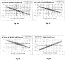
- Actually, it is known that macrobending losses decrease when the core surface integral V01 increases and when the cladding surface integral V02 decreases. The inventors have hence worked out that there must be a positive number k, which allows describing macrobending losses by a mathematical function of the type:

- The same reasoning applies with the cable cutoff wavelength, which tends to increase when the core surface integral V01 increases and when the cladding surface integral V02 decreases. Hence, there must also be a positive number g, which allows describing the behaviour of the cable cut off wavelength by a mathematical function of the type:

- By trial and error, the inventors have found out that for k=g=0.2326, there is a strong correlation between the f function and the macrobending losses at bending radii of 15mm and 10mm on the one hand, and the cable cut-off wavelength on the other hand.
- They have hence derived that the optical fibre of the present disclosure should fulfil the criterion: 25.7 × 10⁻³ ≤ V 01 - 0.2326V 02 ≤ 26.8 × 10⁻³, in order for it to comply with the requirements of the ITU-T G.657.A2 Recommendation at a MFD at 1310nm between 9.0 and 9.2 microns.
- Moreover, a range for the ratio r
0 / r1 between 0.1 and 0.6 is required to have a Zero chromatic Dispersion Wavelength (ZDW) between 1300 nm and 1324 nm (which is required for compliance with the ITU G657.A2 standard). A preferred range for r0 / r1 is between 0.2 and 0.5, while an even narrower range between 0.25 and 0.45 provides a robust working range. - According to a first embodiment of the present disclosure, r 2 = r 1 and a trench ranging from r 2 to r 3 surrounds the core. The core surface integral may hence be approximated as

- According to a second embodiment of the present disclosure, the cladding comprises an intermediate cladding ranging from radius r1 to radius r2>r1 and having a refractive index n2, and the trench surrounds the intermediate cladding.
- Such an intermediate cladding eases the optical fibre manufacturing process when it relies on the OVD ("Outside Vapor Deposition") technique.
- According to this second embodiment, the core surface integral may hence be approximated as

- According to a preferred aspect of this second embodiment, the refractive-index difference of the intermediate cladding with respect to the outer cladding Δn 2 = 0. The intermediate cladding hence presents a refractive index which is equivalent to that of the external cladding. Such an intermediate cladding is void of any dopant and constitutes a buffer zone between the up-doped core and the down-doped trench.
- According to an embodiment of the present disclosure, the core outer radius r1 is between 5.4µm and 8.0µm.
- According to an embodiment of the present disclosure, the trench outer radius r3 is between 16µm and 22µm.
- According to an embodiment of the present disclosure, the refractive-index difference of the centre part of the core with respect to the outer cladding Δn 0 = n 0 - n 4 is between 5×10⁻³ and 6×10⁻³.
- According to an embodiment of the present disclosure, such an optical fibre has a Mode Field Diameter at 1310nm between 9.0µm and 9.2µm.
- According to an embodiment of the present disclosure, said optical fibre has a maximum Cable cut-off wavelength of 1240nm.
- Actually, the ITU-T G.657.A2 Recommendation specifies a maximum value of the Cable Cut-off Wavelength of 1260nm. However, it appears reasonable to target a lower maximum Cable Cut-off Wavelength, around 1240nm, to ensure that all manufactured optical fibres will pass the cable cut-off recommendation. Targeting a cable cut-off wavelength at 1260nm is not robust as it would induce 50% of the produced optical fibres out of the G. 657.A2 Recommendation, because of manufacturing defects. Targeting cable cut-off wavelength below 1240nm is needed to ensure a robust production.
- Throughout this document, the Cable Cut-Off wavelength (CCO) corresponds to the cut-off wavelength in cable λcc such as defined by Subcommittee 86A of the International Electrotechnical Commission in the IEC 60793-1-44 standard.
- According to an embodiment of the present disclosure, said optical fibre complies with the requirements of the ITU-T G.657.A2 standard.
- The present invention also relates to an optical fibre transmission system comprising at least one single mode fibre according to the invention.
- Other features and advantages of embodiments of the invention shall appear from the following description, given by way of an indicative and non-exhaustive example and from the appended drawings, of which:
-
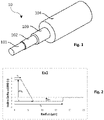
Figure 1 schematically depicts an isometric view of an exemplary single mode optical fiber according to one or more embodiments described herein; -
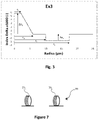
Figure 2 graphically provides the illustrative refractive index profile of single mode optical fibers according to a first embodiment of the present disclosure; -
Figure 3 graphically provides the illustrative refractive index profile of single mode optical fibers according to a second embodiment of the present disclosure; -
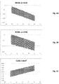
Figures 4A, 4B and 4C provide simulation results for macrobending losses and cable cut-off wavelength of exemplary fibers expressed as a function of f=V01; -
Figures 5A, 5B and 5C provide simulation results for macrobending losses and cable cut-off wavelength of exemplary fibers expressed as a function of f=V01-V02; -
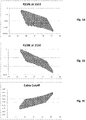
Figures 6A to 6G provide simulation results for macrobending losses and cable cut-off wavelength of exemplary fibers expressed as a function of f=V01-0.2326×V02; -
Figure 7 illustrates an optical link according to an embodiment of the present disclosure. - The components in the figures are not necessarily to scale, emphasis instead being placed upon illustrating the principles of the invention.
- Reference will now be made in detail to embodiments of single mode optical fibers, examples of which are illustrated in the accompanying drawings. Whenever possible, the same reference numerals will be used throughout the drawings to refer to the same or like parts.
- One embodiment of a bending-loss insensitive single mode optical fiber according to the present disclosure is schematically depicted in isometric view in
Figure 1 . Theoptical fiber 10 generally has aglass core 101 surrounded by a glass cladding. More precisely, theoptical fiber 10 comprises three or four abutting concentric regions, namely: - a
trapezoid core 101, with an outer radius r1; - an optional
intermediate cladding 102, with an inner radius r1 and an outer radius r2; - a trench, or depressed cladding, 103, with an inner radius r2 and an outer radius r3;
- an
outer cladding 104, ranging from an inner radius r3 to the end of the glass part of the fiber, with a refractive index nCI. - In embodiments of the present disclosure with no
intermediate cladding 102, thetrench 103 directly abuts thecore 101, and ranges from an inner radius r1 to an outer radius r3. - In embodiments of the present disclosure, the
glass core 101 generally has an outer radius r1 between 5.4 µm and 8.0 µm. Moreover, thedepressed cladding 103 has an outer radius r3 between 16 µm and 22 µm. Thecore 101 has a trapezoid shape, with a small basis radius r0 and a large basis radius r1. The small basis over large basis trapezoid ratio r0/r1 is ranging from 0.1 to 0.6, typically ranging from about 0.2 to about 0.5, preferably from about 0.25 to about 0.45. - In the embodiments shown and described herein, the
core 101 and the cladding generally comprise silica, specifically silica glass. The cross-section of theoptical fiber 10 may be generally circular-symmetric with respect to the center of thecore 101. In some embodiments described herein, the radius of the glass portion of theoptical fiber 10 is about 62.5 µm. However, it should be understood that the dimensions of the cladding may be adjusted so that the radius of the glass portion of the optical fiber may be greater than or less than 62.5 µm. Theoptical fiber 10 also comprises a coating surrounding the cladding. Such a coating may comprise several layers, and it may notably be a dual-layer coating, although these different layers are not shown onfigure 1 . - The different portions in the cladding may comprise pure silica glass (SiO2), silica glass with one or more dopants, which increase the index of refraction (e.g. GeO2 or any other known dopant), such as when the portion of the cladding is "up-doped" " (e.g. for the intermediate cladding 102), or silica glass with a dopant, which decreases the index of refraction, such as fluorine, such as when the portion of the cladding is "down-doped" (e.g. for the trench 103).
- The trapezoid shape of the
core 101 may be obtained by gradually adjusting the concentration of at least two dopants in the center part of the core. -
Figures 2 and3 show diagrams of the index profile of a fibre constituting a first (referenced as Ex1) and a second (referenced as Ex3) embodiment of the invention. - In the first embodiment illustrated by
figure 2 , the index profile is a trapezoid type index profile with a trench, and it presents, starting from the centre of the fibre: - a centre part of the core having a substantially constant refractive index n0 greater than that of the cladding n4;
- a first annular portion of the core, in which the index decreases in substantially linear manner, from the index n0 of the centre part of the core to the index nt of the
depressed cladding 103. Such an annular portion of the core is also called "transition part" of the core's trapezoid-like index profile, throughout the present document; - a depressed cladding, or
trench 103; - an
outer cladding 104. - The fibre as a whole thus constitutes a fibre having a so-called "trapezoid-like" profile.
- The centre part of the
core 101 has a radius r0 and an index difference Δn0 relative to the outer cladding. In the transition part of the core, the refractive index difference decreases substantially linearly. The refractive index of the core typically has a trapezoid shape. Accordingly, the refractive-index difference Δn(r) between the central core and the outer cladding depends on the distance r from the centre of the optical fibre (e.g. decreasing as the distance from the centre of the optical fibre increases). As used herein, the term "refractive-index difference" does not exclude a refractive-index difference of zero. - The depressed cladding, or buried trench, 103 has a radius r3 and a refractive-index difference Δnt with respect to the outer cladding that is typically constant. As used herein, the term "buried trench" is used to designate a radial portion of the optical fibre having a refractive index lower than the refractive index of the outer cladding.
- The
outer cladding 104 ranges from a radius r3 to the end of the glass part of the single mode fibre. - In the second embodiment illustrated by
figure 3 , the index profile is a trapezoid type index profile with a trench, and it presents, starting from the centre of the fibre: - a centre part of the core having a substantially constant refractive index n0 greater than that of the cladding n4;
- a first annular portion of the core, in which the index decreases in substantially linear manner, from the index n0 of the centre part of the core to the index n2 of the
intermediate cladding 102. Such an annular portion of the core is also called "transition part" of the core's trapezoid-like index profile, throughout the present document; - an
intermediate cladding 102; - a depressed cladding, or
trench 103; - an
outer cladding 104. - The fibre as a whole thus constitutes a fibre having a so-called "trapezoid-like" profile.
- Like in the embodiment of
figure 2 , the centre part of thecore 101 has a radius r0 and an index difference Δn0 relative to the outer cladding. In the transition part of the core, the refractive index difference decreases substantially linearly. The refractive index of the core typically has a trapezoid shape. Accordingly, the refractive-index difference Δn(r) between the central core and the outer cladding depends on the distance r from the centre of the optical fibre (e.g. decreasing as the distance from the centre of the optical fibre increases). As used herein, the term "refractive-index difference" does not exclude a refractive-index difference of zero. - The
intermediate cladding 102 has a radius r2 and a refractive-index difference Δn2 with respect to the outer cladding that is typically constant. In the peculiar embodiment illustrated byfigure 3 , Δn 2 = 0. However, in other embodiments, this refractive-index difference may be different from zero (see exemplary embodiment Ex4 described later on in this document). The depressed cladding, or buried trench, 103 has a radius r3 and a refractive-index difference Δnt with respect to the outer cladding that is typically constant. As used herein, the term "buried trench" is used to designate a radial portion of the optical fibre having a refractive index lower than the refractive index of the outer cladding. - The
outer cladding 104 ranges from a radius r3 to the end of the glass part of the single mode fibre. -
Figures 2 and3 differ from each other by the presence of anintermediate cladding 102 between the trapezoid core and the trench. - In both
figures 2 and3 , refractive indexes n(r) are given at a 633 nm wavelength (i.e. the wavelength at which the profile is measured thanks to commercial apparatus) relatively to the outer cladding index n4. These indexes are thus also called "index delta". More generally, throughout the present document, all refractive indices are given at a wavelength λ = 633nm. - Table 2 below draws a comparison of the refractive index designs of two exemplary embodiments Ex1 and Ex2 of
figure 2 with an equivalent step index single mode fibre Comp Ex. The values in Table 2 correspond to the theoretical refractive-index profiles.TABLE 2 ratio r1 r3 Δn0 Δnt r0/r1 (µm) (µm) ×1000 ×1000 Comp Ex 1 4.34 17.50 5.29 -0.16 Ex1 0.35 6.90 17.50 5.54 -1.23 Ex2 0.35 6.88 20.00 5.41 -1.35 - The first column of Table 2 lists the exemplary and comparative optical fibres. The following columns provide, for each single mode fibre listed in the first column:
- the ratio r0/r1 of the centre part of the core radius to the transition part of the core outer radius;
- the outer radius r1 of the transition part of the core, expressed in µm ;
- the outer radius r3 of the trench, expressed in µm ;
- the index delta Δn0 of the centre part of the core ;
- the index delta Δnt of the trench.
- The refractive index differences in Table 2 (as well as in all the other tables throughout the present document) have been multiplied by 1000, as are the ordinate values in
Figures 2 and3 (for example, for the first exemplary embodiment of the invention Ex1, the index delta of the centre part of the core is 5.29 ×10⁻³). The refractive-index values were measured at a wavelength of 633 nanometres. - Table 3 below details the refractive index design of exemplary embodiments Ex3 and Ex4 of
figure 3 . The values in Table 3 correspond to the theoretical refractive-index profiles. It must be noted that the overall refractive-index profile of exemplary embodiment Ex4 corresponds to the one depicted infigure 3 , except for the fact that the refractive index difference of the intermediate cladding is not zero.TABLE 3 Ratio r1 r2 r3 Δn0 Δn2 Δnt r0/r1 (µm) (µm) (µm) ×1000 ×1000 ×1000 Ex3 0.35 5.91 10.00 17.50 5.77 0.00 -1.75 Ex4 0.35 5.78 10.00 17.50 5.87 0.20 -2.00 - The first column of Table 3 gives the reference of the exemplary optical fibres. The following columns provide for the single mode fibres listed in the first column:
- the ratio r0/r1 of the centre part of the core radius to the transition part of the core outer radius;
- the outer radius r1 of the transition part of the core, expressed in µm ;
- the outer radius r2 of the intermediate cladding, expressed in µm ;
- the outer radius r3 of the trench, expressed in µm ;
- the index delta Δn0 of the centre part of the core ;
- the index delta Δn2 of the intermediate cladding ;
- the index delta Δnt of the trench.
- Both in the embodiments of
figures 2 and3 , the core index Δn0 is typically ranging from about 5.0 × 10⁻³ to about 6.0 × 10⁻³; the trench index Δnt is typically ranging from about -2.0 × 10⁻³ to about -0.9 × 10⁻³. - Table 4 (below) shows optical transmission characteristics for optical single mode fibres having the refractive-index profiles depicted in Table 2 and Table 3, compared with the optical transmission characteristics recommended in the ITU-T G.657.A2 standard. The first column identifies the minimum and maximum G.657.A2 recommended range, and the exemplary and comparative optical fibres. The next columns provide, for each optical fibre:
- the Cable Cut-off wavelength (CCO) expressed in nm;
- the Mode Field Diameter at 1310nm (MFD 1310) expressed in µm;
- the Mode Field Diameter at 1550nm (MFD 1550) expressed in µm;
- the Zero chromatic Dispersion Wavelength (ZDW) expressed in nm;
- the Zero Dispersion Slope (ZDS) expressed in ps/nm2-km;
- the Chromatic Dispersion at respective 1550nm (DC 1550) and 1625nm (DC 1625) wavelength expressed in ps/nm-km.
- The comparative example Comp Ex, corresponding to a step-index single mode fibre, presents the same MFD at 1310nm and Cable Cut-off as examples Ex1 to Ex3. However, examples Ex1 to Ex4 are all compliant with ITU-T G.657.A2 Recommendation, which is not the case of the comparative example Comp Ex.
- It must be noted that the cable cutoff target needs to be significantly below the maximum accepted level of 1260nm. Targeting a cable cutoff at 1260nm is not robust as it will by definition induce 50% of the production out of the ranges of values recommended by the G.657.A2 standard. In the above examples, the cable cutoff wavelength is targeted to be around 1210nm that is ensuring robust production, i.e nearly all fibers can pass the cable cutoff recommendation. More generally, targeting cable cutoff below 1240nm is recommended to ensure a robust production.
- As may be observed in Table 4, all the exemplary fibers Ex1 to Ex4 target a nominal Mode Field Diameter at 1310nm of 9 microns.
- Table 5 (below) shows macrobending losses for optical fibres having the refractive-index profiles depicted in Tables 2 and 3 for the wavelengths of 1550 nanometres and 1625 nanometres for radii of curvature of 15 millimetres, 10 millimetres, 7,5 millimetres and 5 millimetres, such as:
- R15mm Macro bend loss at 1550nm (R15BL at 1550), expressed in dB/10T, where 10T stands for 10 turns;
- R10mm Macro bend loss at 1550nm (R10BL at 1550), expressed in dB/1T, where 1T stands for 1 turn;
- R7.5mm Macro bend loss at 1550nm (R7.5BL at 1550), expressed in dB/1T, where 1T stands for 1 turn;
- R5mm Macro bend loss at 1550nm (R5BL at 1550), expressed in dB/1T, where 1T stands for 1 turn;
- R15mm Macro bend loss at 1625nm (R15BL at 1625), expressed in dB/10T, where 10T stands for 10 turns;
- R10mm Macro bend loss at 1625nm (R10BL at 1625), expressed in dB/1T, where 1T stands for 1 turn;
- R7.5mm Macro bend loss at 1625nm (R7.5BL at 1625), expressed in dB/1T, where 1T stands for 1 turn;
- R5mm Macro bend loss at 1625nm (R5BL at 1625), expressed in dB/1T, where 1T stands for 1 turn.
- Table 5 also provides the maximum recommended value by the ITU-T G.657.A2 standard.
TABLE 5 R15BL at 1550 R10BL at 1550 R7.5BL at 1550 R5BL at 1550 R15BL at 1625 R10BL at 1625 R7.5BL at 1625 R5BL at 1625 (dB/10T) (dB/1T) (dB/1T) (dB/1T) (dB/10T) (dB/1T) (dB/1T) (dB/1T) G.657.A2 max 0.03 0.1 0.5 0.1 0.2 1.0 Comp Ex 0.022 0.17 1.3 10 0.14 0.55 3.0 16 Ex1 0.013 0.05 0.3 1.4 0.08 0.17 0.6 2.6 Ex2 0.016 0.04 0.1 1.0 0.08 0.10 0.3 1.8 Ex3 0.016 0.06 0.3 1.3 0.08 0.16 0.6 2.4 Ex4 0.009 0.04 0.2 0.9 0.05 0.11 0.4 1.7 - In accordance with Tables 4 and 5 (above), the optical fibres according to embodiments of the invention show bending losses, which are less than the comparative optical fibre, which has a step-index profile.
- The four refractive index profile examples Ex1, Ex2, Ex3 and Ex4 according to embodiments of the invention, described in Tables 2 to 5, as well as in
figures 1 and 2 , comply with the ITU-T G. 657.A2 Recommendation. - Table 6 below provides the features of three other exemplary optical fibres Ex5 to Ex7, which refractive index profile corresponds to the one depicted in
figure 2 , but which, contrarily to the exemplary fibres of Table 2, target a MFD at 1310nm of 9.2 microns.TABLE 6 ratio r1 r3 Δn0 Δnt r0/r1 (µm) (µm) ×1000 ×1000 Ex5 0.35 7.00 17.50 5.5 -0.93 Ex6 0.35 6.99 20.00 5.41 -1 Ex7 0.35 6.97 20.00 5.29 -1.1 - The structure and units of Table 6 is identical to that of Table 2 and is therefore not detailed here. Similarly, Table 7 below corresponds to Table 4 above and provides the optical characteristics of exemplary optical fibres Ex5-Ex7; Table 8 below corresponds to Table 5 above and provides the macrobending losses of exemplary optical fibres Ex5-Ex7.
TABLE 7 CCO MFD 1310 MFD 1550ZDW ZDS DC 1550 DC 1625 (nm) (µm) (µm) (nm) (ps/nm2-km) (ps/nm-km) (ps/nm-km) G.657.A2 min 8.6 1300 13.3 17.2 G.657.A2 max 1260 9.2 1324 0.092 18.6 23.7 Ex5 1236 9.2 10.29 1312 0.090 17.4 21.8 Ex6 1235 9.2 10.29 1312 0.090 17.4 21.8 Ex7 1214 9.2 10.29 1312 0.090 17.4 21.7 TABLE 8 R15BL at 1550 R10BL at 1550 R7.5BL at 1550 R5BL at 1550 R15BL at 1625 R10BL at 1625 R7.5BL at 1625 R5BL at 1625 (dB/10T) (dB/1T) (dB/1T) (dB/1T) (dB/10 T) (dB/1T) (dB/1T) (dB/1T) G.657.A2 max 0.03 0.1 0.5 0.1 0.2 1.0 Ex5 0.012 0.07 0.4 2.4 0.07 0.20 0.9 4.1 Ex6 0.013 0.05 0.2 1.7 0.07 0.14 0.5 3.2 Ex7 0.025 0.06 0.3 1.8 0.12 0.17 0.6 3.3 - We now present interesting tools and methods for defining acceptable profile ranges for single mode optical fibres according to the present disclosure.
- Each section of the optical fibre profile may be defined using surface integrals. The term "surface" should not be understood geometrically but rather should be understood as a value having two dimensions.
- Accordingly, the central core may define a surface integral V01 and the cladding may define a surface integral V02 respectively defined by the following equations:


- For exemplary optical fibres which refractive index profile corresponds to the first embodiment of
figure 2 , the cladding surface integral may be expressed as:
- Table 9 (below) completes Tables 2, 3 and 6 (above) with the values of the surface integrals V01 and V02 described above for the exemplary embodiments of the invention Ex1 to Ex7, as well as for their comparative step index single mode fibre Comp Ex. All the examples in Table 9 are hence the same as in Tables 2, 3 and 6. The values in Table 9 correspond to the theoretical refractive-index profiles.
- The first column in Table 9 lists the exemplary and comparative optical fibres. The three other columns provide respective values for the surface integrals V01 and V02, as well as for the polynomial V01-0.2326V02. The integrals in Table 9 have been multiplied by 1000.
TABLE 9 V01 ×1000 V02 ×1000 (V01-0.2326V02) ×1000 (µm) (µm) (µm) Comp Ex 22.96 -2.11 23.45 Ex1 23.04 -13.04 26.08 Ex2 22.11 -17.71 26.23 Ex3 23.02 -13.13 26.07 Ex4 23.27 -14.16 26.56 Ex5 23.87 -9.77 26.14 Ex6 23.25 -13.01 26.28 Ex7 22.40 -14.33 25.73 - Tables 10 to 13 (below) provide the features of further exemplary optical fibres Ex8 to Ex35, according to embodiments of the present disclosure, which refractive index profile corresponds to the one depicted in
figure 2 . More precisely, Table 10 corresponds to Table 6, and provides: - the ratio r0/r1 of the centre part of the core radius to the transition part of the core outer radius;
- the outer radius r1 of the transition part of the core, expressed in µm ;
- the outer radius r3 of the trench, expressed in µm ;
- the index delta Δn0 of the centre part of the core ;
- the index delta Δnt of the trench.
- Similarly, Table 11 below corresponds to Table 4 above and provides the optical characteristics of exemplary optical fibres Ex8-Ex35; Table 12 below corresponds to Table 5 above and provides the macrobending losses of exemplary optical fibres Ex8-Ex35. Last, Table 13 below corresponds to Table 9 above and provides the values of the surface integrals V01 and V02 described above for the exemplary embodiments of the invention Ex8 to Ex35. The structure and units in Tables 10-13 are the same as in the previously described corresponding tables.
TABLE 11 CCO MFD 1310 MFD 1550 ZDW ZDS DC 1550 DC 1625 (nm) (µm) (µm) (nm) (ps/nm2-km) (ps/nm-km) (ps/nm-km) G.657.A2 min 8.6 1300 13.3 17.2 G.657.A2 max 1260 9.2 1324 0.092 18.6 23.7 Ex8 1223 9.12 10.23 1318 0.091 17.3 21.7 Ex9 1240 9.18 10.32 1319 0.091 17.1 21.5 Ex10 1219 9.11 10.21 1316 0.091 17.3 21.7 Ex11 1228 9.20 10.29 1314 0.091 17.5 21.9 Ex12 1234 9.19 10.34 1318 0.090 17 21.4 Ex13 1231 9.01 10.05 1313 0.092 17.6 22 Ex14 1202 9.00 10.12 1319 0.090 17 21.3 Ex15 1214 9.11 10.21 1315 0.090 17.3 21.6 Ex16 1234 9.19 10.26 1310 0.091 17.7 22.1 Ex17 1197 9.01 10.05 1311 0.091 17.6 22 Ex18 1224 9.00 10.10 1316 0.090 17.1 21.4 Ex19 1239 9.11 10.16 1310 0.091 17.6 21.9 Ex20 1230 9.10 10.22 1315 0.089 17.1 21.4 Ex21 1225 9.20 10.31 1313 0.090 17.3 21.6 Ex22 1230 9.00 10.00 1306 0.092 18 22.4 Ex23 1231 9.00 10.06 1311 0.090 17.4 21.7 Ex24 1222 9.11 10.17 1310 0.090 17.5 21.8 Ex25 1234 9.20 10.22 1305 0.091 18 22.3 Ex26 1235 9.01 9.98 1303 0.092 18.2 22.6 Ex27 1215 9.00 10.10 1314 0.089 17.1 21.4 Ex28 1232 9.11 10.16 1308 0.090 17.5 21.8 Ex29 1238 9.20 10.24 1306 0.090 17.8 22.1 Ex30 1232 9.01 9.96 1301 0.092 18.3 22.6 Ex31 1216 9.01 10.05 1308 0.089 17.5 21.8 Ex32 1224 9.10 10.12 1305 0.090 17.7 22 Ex33 1231 9.20 10.21 1303 0.091 18 22.3 Ex34 1216 9.00 9.97 1301 0.091 18.2 22.5 Ex35 1236 9.00 10.03 1307 0.089 17.5 21.8 TABLE 12 R15BL at 1550 R10BL at 1550 R7.5BL at 1550 R5BL at 1550 R15BL at 1625 R10BL at 1625 R7.5BL at 1625 R5BL at 1625 (dB/10T) (dB/1T) (dB/1T) (dB/1T) (dB/10T) (dB/1T) (dB/1T) (dB/1T) G.657.A2 max 0.03 0.1 0.5 0.1 0.2 1.0 Ex8 0.021 0.03 0.1 0.5 0.10 0.07 0.19 0.89 Ex9 0.016 0.02 0.1 0.6 0.07 0.06 0.18 1.19 Ex10 0.014 0.05 0.2 1.2 0.08 0.15 0.53 2.11 Ex11 0.014 0.04 0.2 0.9 0.07 0.12 0.38 1.58 Ex12 0.015 0.04 0.2 1.5 0.07 0.10 0.37 2.79 Ex13 0.005 0.03 0.1 0.7 0.03 0.09 0.34 1.29 Ex14 0.016 0.05 0.2 1.3 0.09 0.16 0.54 2.42 Ex15 0.017 0.06 0.3 1.7 0.10 0.19 0.67 2.94 Ex16 0.023 0.02 0.1 0.5 0.10 0.06 0.18 0.97 Ex17 0.018 0.05 0.2 0.9 0.10 0.15 0.44 1.58 Ex18 0.009 0.04 0.2 1.2 0.05 0.11 0.41 2.18 Ex19 0.010 0.02 0.1 0.8 0.05 0.07 0.23 1.47 Ex20 0.012 0.04 0.2 2.1 0.07 0.12 0.47 3.92 Ex21 0.019 0.06 0.3 2.2 0.10 0.18 0.66 3.90 Ex22 0.011 0.02 0.1 0.4 0.06 0.06 0.17 0.70 Ex23 0.014 0.02 0.1 0.7 0.07 0.06 0.19 1.44 Ex24 0.016 0.05 0.2 1.6 0.09 0.15 0.55 2.93 Ex25 0.013 0.04 0.2 1.0 0.07 0.12 0.41 1.88 Ex26 0.006 0.03 0.2 0.8 0.04 0.09 0.36 1.43 Ex27 0.015 0.04 0.2 2.2 0.08 0.13 0.51 4.16 Ex28 0.011 0.05 0.2 1.9 0.07 0.15 0.59 3.48 Ex29 0.012 0.05 0.3 1.9 0.07 0.16 0.63 3.34 Ex30 0.013 0.02 0.1 0.4 0.07 0.06 0.17 0.79 Ex31 0.017 0.04 0.2 1.3 0.09 0.11 0.38 2.54 Ex32 0.016 0.06 0.3 1.7 0.09 0.17 0.61 3.13 Ex33 0.019 0.04 0.2 1.4 0.10 0.13 0.42 2.57 Ex34 0.017 0.04 0.2 0.8 0.09 0.12 0.37 1.59 Ex35 0.008 0.03 0.2 1.6 0.05 0.09 0.38 3.20 TABLE 13 V01 ×1000 V02 ×1000 (V01-0.2326V02) ×1000 (µm) (µm) (µm) Comp Ex 22.96 -2.11 23.45 Ex8 20.72 -22.92 26.05 Ex9 21.38 -22.32 26.57 Ex10 23.01 -14.28 26.33 Ex11 22.46 -16.64 26.33 Ex12 22.90 -15.89 26.60 Ex13 22.89 -16.12 26.64 Ex14 22.92 -14.19 26.22 Ex15 23.05 -12.77 26.02 Ex16 20.29 -24.23 25.93 Ex17 21.86 -17.11 25.83 Ex18 23.32 -14.33 26.65 Ex19 22.33 -18.96 26.74 Ex20 23.05 -13.76 26.25 Ex21 23.03 -12.27 25.88 Ex22 21.17 -23.13 26.55 Ex23 21.25 -22.39 26.46 Ex24 22.76 -13.67 25.95 Ex25 22.59 -15.92 26.29 Ex26 23.02 -16.15 26.78 Ex27 22.69 -13.76 25.89 Ex28 23.20 -12.09 26.01 Ex29 23.23 -12.06 26.04 Ex30 21.14 -23.64 26.64 Ex31 22.10 -16.75 25.99 Ex32 22.66 -13.26 25.75 Ex33 22.06 -16.66 25.93 Ex34 21.92 -18.21 26.16 Ex35 22.97 -14.44 26.33 - Optical fibres according to embodiments of the invention typically target a MFD at 1310nm greater than or equal to 9 microns, and have the following properties:
- a ratio r0/r1 of the centre part of the core's radius to the transition part of the core's radius ranges between 0.10 and 0.60 (which is required to keep the Zero chromatic Dispersion Wavelength ZDW between 1300 nm and 1324 nm), preferably ranging between 0.20 and 0.50, more preferably between 0.25 and 0.45 (which provides a robust working range);
- a core surface integral V01 preferably ranging between about 20×10-3 µm and about 24×10-3 µm ;
- a cladding surface integral V02 preferably ranging between -25×10-3 µm and -9×10⁻³ µm ;
- the relationship V01-0.2326×V02 between the core surface integral and the cladding surface integral preferably ranging between 25.7×10⁻³ µm and 26.8×10⁻³ µm.
- Actually, it is known that macrobending losses decrease when the core surface integral V01 increases and when the cladding surface integral V02 decreases. The inventors have hence worked out that there must be a positive number k, which allows describing macrobending losses by a mathematical function of the type:

- The same reasoning applies with the cable cutoff wavelength, which tends to increase when the core surface integral V01 increases and when the cladding surface integral V02 decreases. Hence, there must also be a positive number g, which allows describing the behaviour of the cable cut off wavelength by a mathematical function of the type:

- By trial and error, the inventors have found out that for k=g=0.2326, there is a strong correlation between the f function and the macrobending losses at bending radii of 15mm and 10mm on the one hand, and the cable cut-off wavelength on the other hand.
-
Figures 4 to 6 allow illustrating this finding. More precisely,figures 4A and 4B respectively illustrate on the y-axis, the macrobending losses, for optical fibres according to embodiments of the present disclosure targeting a MFD at 1310nm of 9 microns for the wavelength of 1550 nanometres for radii of curvature of 15 millimetres and 10 millimetres (R15BL at 1550 nm and R10BL at 1550 nm), expressed in dB/10T, where 10T stands for 10 turns, as a function of the above-expressed f function, when k=0, on the x-axis.Figure 4C illustrates the cable cut-off wavelength (CCO), expressed in nm, for optical fibres according to embodiments of the present disclosure targeting a MFD at 1310nm of 9 microns, as a function of the above-expressed f function, when g=0, on the x-axis. - As may be observed, the values of macrobending losses and cable cut-off wavelength are dispersed.
- The same may be observed on
figures 5A to 5C , which are similar tofigures 4A to 4C , except for the fact that the k and g parameters are set to 1. - However,
figures 6A to 6G illustrate the fact that there is a strong correlation between the above-expressed f function and both the macrobending losses and the cable cut-off wavelength when k=g=0.2326. All these figures are plotted through simulations carried out for exemplary optical fibres according to the present disclosure, both targeting a MFD at 1310nm of 9 or 9.2 microns, corresponding to the lower and upper limits of the present disclosure. -
Figure 6A provides the macrobending losses for such optical fibres for the wavelength of 1550 nanometres for a radius of curvature of 15 millimetres (R15mm BL at 1550 nm), expressed in dB/10T, where 10T stands for 10 turns, as a function of the above-expressed f function, when k=0.2326, on the x-axis. -
Figure 6B provides the macrobending losses for such optical fibres for the wavelength of 1550 nanometres for a radius of curvature of 10 millimetres (R10mm BL at 1550 nm), expressed in dB/10T, where 10T stands for 10 turns, as a function of the above-expressed f function, when k=0.2326, on the x-axis. -
Figure 6C provides the macrobending losses for such optical fibres for the wavelength of 1550 nanometres for a radius of curvature of 7.5 millimetres (R7.5mm BL at 1550 nm), expressed in dB/10T, where 10T stands for 10 turns, as a function of the above-expressed f function, when k=0.2326, on the x-axis. -
Figure 6D provides the macrobending losses for such optical fibres for the wavelength of 1625 nanometres for a radius of curvature of 15 millimetres (R15mm BL at 1625 nm), expressed in dB/10T, where 10T stands for 10 turns, as a function of the above-expressed f function, when k=0.2326, on the x-axis. -
Figure 6E provides the macrobending losses for such optical fibres for the wavelength of 1625 nanometres for a radius of curvature of 10 millimetres (R10mm BL at 1625 nm), expressed in dB/10T, where 10T stands for 10 turns, as a function of the above-expressed f function, when k=0.2326, on the x-axis. -
Figure 6F provides the macrobending losses for such optical fibres for the wavelength of 1625 nanometres for a radius of curvature of 7.5 millimetres (R7.5mm BL at 1625 nm), expressed in dB/10T, where 10T stands for 10 turns, as a function of the above-expressed f function, when k=0.2326, on the x-axis. -
Figure 6G provides the cable cut-off wavelength for such optical fibres, expressed in nanometers, as a function of the above-expressed f function, when g=0.2326, on the x-axis. - Hence, as may be observed on
figures 6D and 6E , for a nominal MFD at 1310nm between 9.0µm and 9.2µm, it is necessary to have 25.7 × 10⁻³ ≤ V 01 - 0.2326V02, in order to achieve macrobending losses at bending radii of 15mm and 10mm compliant with the requirements of the ITU-T G. 657.A2 Recommendation, which maximum accepted level is showed by the horizontal dashed line. -
Figure 7 illustrates anoptical link 70 according to an embodiment of the present disclosure. Such an optical link comprises p spans of optical fibers, with p ≥ 2, which are spliced together.Figure 7 only showsoptical fiber 701 andoptical fiber 70p, all the other potential optical fibers in the optical link being symbolized by dashed lines. At least one of the optical fibers inoptical link 70 is such that it comprises the features of one embodiment described above. In other words, at least one of the optical fibers complies with the requirements of ITU-T G.657.A2 Recommendation, targets a Mode Field Diameter at 1310nm greater than or equal to 9 microns and shows the specific design of the refractive index profile described above in relation tofigures 2 and3 , and notably, a trapezoid core, with a large but shallow trench. This optical fiber may be spliced inoptical link 70 with a standard single-mode optical fiber compliant with the requirements of ITU-T.G. 652.D recommendation. - We now describe an exemplary method of manufacturing an optical fibre according to embodiments of the present disclosure. Such a manufacturing method comprises a first step of Chemical Vapour Deposition to form a core rod. During the Chemical Vapour Deposition doped or non-doped glass layers are deposited. The deposited glass layers form the core refractive index profile of the final optical. In a second step the core rod is provided with an external overcladding for increasing its diameter to form a preform. The overcladding may be derived from pre-formed silica tubes or by deposition of glass layers on the outer circumference of the core rod. Various techniques could be used for providing an overcladding by deposition of glass layers, such as Outside Vapour Deposition (OVD) or Advanced Plasma and Vapour Deposition (APVD). In a third step, the optical fibre is obtained by drawing the preform in a fibre drawing tower.
- In order to fabricate the core-rod, a tube or substrate is generally mounted horizontally and held in a glass-making lathe. Thereafter, the tube or substrate is rotated and heated or energised locally for depositing components that determine the composition of the core-rod. Those of ordinary skill in the art will appreciate that the composition of the core-rod determines the optical characteristics of the fibre.
- In this regard, both the centre part and the transition part of the core, the intermediate cladding and the trench are typically obtained using plasma chemical vapour deposition (PCVD) or furnace chemical vapour deposition (FCVD), which enable large quantities of fluorine and germanium to be incorporated into the silica and which enable a gradual change of their concentrations in the transition part of the core. The PCVD technique is for example described in patent document
US Re30,635 orUS 4,314,833 . - Other techniques could also be used to form the core-rod, such as vapour axial deposition (VAD) or outside vapour deposition (OVD).
- Optical fibres in accordance with the present invention are well suited for use in various optical communication systems. They are particularly suited for terrestrial transmission systems, as well as for fibre-to-the-home (FTTH) systems.
- Moreover, they are typically compatible with conventional optical fibres, which make them appropriate for use in many optical communication systems. For example, the optical fibres according to embodiments of the invention are typically compatible with conventional optical fibres with respect to mode field diameter, thereby facilitating good fibre-to-fibre coupling.
- In the specification and/or figure, typical embodiments of the invention have been disclosed. The present invention is not limited to such exemplary embodiments.
| CCO | MFD 1310 | | | ZDS | DC | 1550 | DC 1625 | |
| (nm) | (µm) | (µm) | (nm) | (ps/nm2-km) | (ps/nm-km) | (ps/nm-km) | ||
| G.657.A2 min | 8.6 | 1300 | 13.3 | 17.2 | ||||
| G.657.A2 max | 1260 | 9.2 | 1324 | 0.092 | 18.6 | 23.7 | ||
| Comp Ex | 1210 | 9 | 10.11 | 1312 | 0.086 | 16.5 | 20.7 | |
| Ex1 | 1210 | 9 | 10.05 | 1312 | 0.090 | 17.4 | 21.7 | |
| Ex2 | 1210 | 9 | 10.06 | 1312 | 0.090 | 17.4 | 21.7 | |
| Ex3 | 1210 | 9 | 10.23 | 1317 | 0.090 | 17.2 | 21.8 | |
| Ex4 | 1228 | 9 | 10.25 | 1320 | 0.090 | 17.1 | 21.7 |
| ratio | r1 | r3 | Δn0 | Δnt | |
| r0/r1 | (µm) | (µm) | ×1000 | ×1000 | |
| Ex8 | 0.20 | 8.00 | 20.00 | 5.59 | -1.91 |
| Ex9 | 0.20 | 7.90 | 21.43 | 5.61 | -1.65 |
| Ex10 | 0.25 | 7.65 | 17.30 | 5.70 | -1.48 |
| Ex11 | 0.25 | 7.85 | 18.12 | 5.55 | -1.62 |
| Ex12 | 0.25 | 7.43 | 21.49 | 5.61 | -1.13 |
| Ex13 | 0.25 | 7.95 | 16.05 | 5.80 | -1.99 |
| Ex14 | 0.25 | 7.33 | 18.16 | 5.79 | -1.31 |
| Ex15 | 0.30 | 7.21 | 17.94 | 5.56 | -1.19 |
| Ex16 | 0.30 | 7.56 | 20.73 | 5.12 | -1.84 |
| Ex17 | 0.30 | 7.42 | 17.03 | 5.49 | -1.78 |
| Ex18 | 0.30 | 7.06 | 19.52 | 5.70 | -1.15 |
| Ex19 | 0.35 | 7.06 | 20.80 | 5.35 | -1.38 |
| Ex20 | 0.35 | 6.78 | 21.74 | 5.48 | -0.92 |
| Ex21 | 0.35 | 6.91 | 19.96 | 5.39 | -0.94 |
| Ex22 | 0.35 | 7.25 | 18.93 | 5.28 | -1.98 |
| Ex23 | 0.35 | 6.90 | 21.93 | 5.28 | -1.49 |
| Ex24 | 0.40 | 6.67 | 19.57 | 5.33 | -1.06 |
| Ex25 | 0.40 | 6.98 | 18.60 | 5.21 | -1.37 |
| Ex26 | 0.40 | 7.01 | 16.51 | 5.42 | -1.70 |
| Ex27 | 0.40 | 6.43 | 21.55 | 5.43 | -0.91 |
| Ex28 | 0.45 | 6.42 | 19.71 | 5.33 | -0.91 |
| Ex29 | 0.45 | 6.55 | 18.98 | 5.26 | -0.97 |
| Ex30 | 0.45 | 6.68 | 19.60 | 5.06 | -1.83 |
| Ex31 | 0.45 | 6.35 | 20.79 | 5.24 | -1.16 |
| Ex32 | 0.50 | 6.23 | 19.23 | 5.19 | -1.02 |
| Ex33 | 0.50 | 6.37 | 20.49 | 5.01 | -1.18 |
| Ex34 | 0.50 | 6.34 | 18.48 | 5.11 | -1.50 |
| Ex35 | 0.50 | 6.10 | 21.63 | 5.33 | -0.93 |
Claims (14)
- A bending-loss insensitive single mode optical fibre (10) having a Mode Field Diameter greater than or equal to 9.0µm at a 1310nm wavelength, said optical fibre (10) having a core (101) surrounded by a cladding (103, 104), the core refractive index profile having a trapezoid-like shape,wherein a centre part of said core (101) has a radius r0 and a refractive index n0 and a transition part of the trapezoid-like core refractive index profile ranges from radius r0 to a radius r1>r0 with a trapezoid ratio r
0 / r1 of said centre part of said core's radius r0 to said transition part's radius r1 between 0.1 and 0.6,wherein said cladding (103, 104) comprises at least one region of depressed refractive index, called a trench (103), ranging from radius r2≥ r1 to radius r3>r2 and having a refractive index nt, and an outer cladding (104) ranging from radius r3 to the end of a glass part of the single mode fibre and having a refractive index n4,characterized in that the refractive-index difference of said trench (103) with respect to said outer cladding (104) Δnt = nt - n 4 is between -2×10⁻³ and -0.9×10⁻³,and in that said core (101) has a surface integral V01 of between about 20×10-3 µm and 24×10-3 µm, the surface integral being defined according to the following equation: wherein said cladding (103, 104) has a surface integral V02 of between about - 25×10-3 µm and -9×10⁻³ µm, the surface integral being defined according to the following equation:
 and wherein said single mode optical fibre fulfils the following criterion:
25.7 × 10⁻³ ≤ V 01 - 0.2326V 02 ≤ 26.8 × 10⁻³. - The bending-loss insensitive single mode optical fibre of claim 1, wherein said trapezoid ratio r
0 / r1 of said centre part of said core's radius r0 to said transition part's radius r1 is between 0.2 and 0.5. - The bending-loss insensitive single mode optical fibre of claim 1 or 2, wherein said trapezoid ratio r
0 / r1 of said centre part of said core's radius r0 to said transition part's radius r1 is between 0.25 and 0.45. - The bending-loss insensitive single mode optical fibre of any of claims 1 to 3, wherein said cladding comprises an intermediate cladding ranging from radius r1 to radius r2>r1 and having a refractive index n2, and wherein said trench surrounds said intermediate cladding.
- The bending-loss insensitive single mode optical fibre of claim 4, wherein said core surface integral

- The bending-loss insensitive single mode optical fibre of claim 4 or 5, wherein the refractive-index difference of said intermediate cladding with respect to said outer cladding Δn 2 = 0.
- The bending-loss insensitive single mode optical fibre of any of claims 1 to 3, wherein r 2 = r 1 and wherein said core surface integral

- The bending-loss insensitive single mode optical fibre of any of claims 1 to 7, wherein the core outer radius r1 is between 5.4µm and 8.0µm.
- The bending-loss insensitive single mode optical fibre of any of claims 1 to 8, wherein the trench outer radius r3 is between 16µm and 22µm.
- The bending-loss insensitive single mode optical fibre of any of claims 1 to 9, wherein the refractive-index difference of said centre part of said core with respect to said outer cladding Δn 0 = n 0 - n 4 is between 5×10⁻³ and 6×10⁻³.
- The bending-loss insensitive single mode optical fibre of any of claims 1 to 10, wherein said optical fibre has a maximum Cable cut-off wavelength of 1240nm.
- The bending-loss insensitive single mode optical fibre of any of claims 1 to 11, wherein said optical fibre has a Mode Field Diameter at 1310 nm between 9.0µm and 9.2µm.
- The bending-loss insensitive single mode optical fibre of any of claims 1 to 12, wherein said optical fibre complies with the requirements of the ITU-T G.657.A2 standard.
- Optical fibre transmission system comprising at least one single mode fibre according to any of claims 1 to 13.
Applications Claiming Priority (1)
| Application Number | Priority Date | Filing Date | Title |
|---|---|---|---|
| PCT/IB2017/001722 WO2019122943A1 (en) | 2017-12-21 | 2017-12-21 | Bending-loss insensitve single mode fibre, with a shallow trench, and corresponding optical system |
Publications (2)
| Publication Number | Publication Date |
|---|---|
| EP3729151A1 EP3729151A1 (en) | 2020-10-28 |
| EP3729151B1 true EP3729151B1 (en) | 2022-04-06 |
Family
ID=61628369
Family Applications (1)
| Application Number | Title | Priority Date | Filing Date |
|---|---|---|---|
| EP17851832.0A Active EP3729151B1 (en) | 2017-12-21 | 2017-12-21 | Bending-loss insensitive single mode fibre, with a shallow trench, and corresponding optical system |
Country Status (8)
| Country | Link |
|---|---|
| US (1) | US10962708B2 (en) |
| EP (1) | EP3729151B1 (en) |
| CN (1) | CN111512200B (en) |
| DK (1) | DK3729151T3 (en) |
| ES (1) | ES2916334T3 (en) |
| PL (1) | PL3729151T3 (en) |
| RU (1) | RU2755736C1 (en) |
| WO (1) | WO2019122943A1 (en) |
Families Citing this family (5)
| Publication number | Priority date | Publication date | Assignee | Title |
|---|---|---|---|---|
| RU2755736C1 (en) | 2017-12-21 | 2021-09-20 | Драка Комтек Франс | Single-mode fibre with shallow groove, insensitive to bending losses, and corresponding optical system |
| JPWO2021079788A1 (en) * | 2019-10-24 | 2021-04-29 | ||
| US11860408B2 (en) | 2021-03-09 | 2024-01-02 | Corning Incorporated | Optical fiber for data centers |
| WO2023009103A1 (en) * | 2021-07-26 | 2023-02-02 | Ofs Fitel, Llc | Optical fibers comprising triangular trench profile |
| CN113716862B (en) * | 2021-09-01 | 2023-03-21 | 中天科技光纤有限公司 | Method and apparatus for manufacturing optical fiber |
Family Cites Families (77)
| Publication number | Priority date | Publication date | Assignee | Title |
|---|---|---|---|---|
| DE2444100C3 (en) | 1974-09-14 | 1979-04-12 | Philips Patentverwaltung Gmbh, 2000 Hamburg | Process for the production of internally coated glass tubes for drawing optical fibers |
| DE2929166A1 (en) | 1979-07-19 | 1981-01-29 | Philips Patentverwaltung | METHOD FOR THE PRODUCTION OF OPTICAL FIBERS |
| US4516826A (en) | 1983-04-21 | 1985-05-14 | At&T Technologies, Inc. | Single mode lightguide fiber having a trapezoidal refractive index profile |
| JPS6252508A (en) | 1985-09-02 | 1987-03-07 | Nippon Telegr & Teleph Corp <Ntt> | Optical fiber |
| US4852968A (en) | 1986-08-08 | 1989-08-01 | American Telephone And Telegraph Company, At&T Bell Laboratories | Optical fiber comprising a refractive index trench |
| JPH0948629A (en) | 1995-08-01 | 1997-02-18 | Sumitomo Electric Ind Ltd | Optical fiber and its production |
| JP3386948B2 (en) | 1996-02-08 | 2003-03-17 | 株式会社フジクラ | Optical fiber |
| ZA9711125B (en) * | 1996-12-12 | 1998-09-22 | Sumitomo Electric Industries | Single-mode optical fiber |
| JPH10274720A (en) * | 1997-01-29 | 1998-10-13 | Sumitomo Electric Ind Ltd | Single mode optical fiber |
| DE19839870A1 (en) | 1998-09-02 | 2000-03-09 | Deutsche Telekom Ag | Single-mode optical fiber |
| FR2790107B1 (en) * | 1999-02-18 | 2001-05-04 | Cit Alcatel | LINE FIBER FOR WAVELENGTH MULTIPLEXED OPTICAL FIBER TRANSMISSION SYSTEMS |
| FR2784197B1 (en) * | 1998-10-05 | 2000-12-15 | Cit Alcatel | MONOMODE FIBER OPTICAL WITH OFFSET DISPERSION WITH LARGE EFFECTIVE AREA |
| KR100661766B1 (en) | 1998-11-02 | 2006-12-28 | 스미토모덴키고교가부시키가이샤 | Single-mode optical fiber and its production method |
| FR2828937B1 (en) * | 2001-08-23 | 2004-02-06 | Cit Alcatel | OPTICAL FIBER FOR WAVELENGTH MULTIPLEXING TRANSMISSION SYSTEM |
| AU2001225460A1 (en) * | 2000-09-27 | 2002-04-08 | Sterlite Optical Technologies Ltd. | Dispersion optimized fiber with low dispersion and optical loss |
| CN1262856C (en) | 2001-04-30 | 2006-07-05 | 斯德莱特光学技术有限公司 | Dispersion shifted fiber having low dispersion slope |
| JP3986842B2 (en) | 2001-07-26 | 2007-10-03 | 株式会社フジクラ | Manufacturing method of optical fiber preform for non-zero dispersion shifted optical fiber |
| US6771865B2 (en) | 2002-03-20 | 2004-08-03 | Corning Incorporated | Low bend loss optical fiber and components made therefrom |
| US7187833B2 (en) | 2004-04-29 | 2007-03-06 | Corning Incorporated | Low attenuation large effective area optical fiber |
| US7221838B2 (en) | 2004-06-23 | 2007-05-22 | Furukawa Electric North America, Inc. | Optical fibers with reduced splice loss and methods for making same |
| JPWO2006016572A1 (en) | 2004-08-10 | 2008-05-01 | 株式会社フジクラ | Single mode optical fiber |
| US7171090B2 (en) | 2005-06-30 | 2007-01-30 | Corning Incorporated | Low attenuation optical fiber |
| FR2893149B1 (en) * | 2005-11-10 | 2008-01-11 | Draka Comteq France | OPTICAL FIBER MONOMODE. |
| FR2896795B1 (en) | 2006-01-27 | 2008-04-18 | Draka Compteq France | PROCESS FOR PRODUCING AN OPTICAL FIBER PREFORM |
| FR2900739B1 (en) | 2006-05-03 | 2008-07-04 | Draka Comteq France | COMPENSATION FIBER OF CHROMATIC DISPERSION |
| US7450807B2 (en) | 2006-08-31 | 2008-11-11 | Corning Incorporated | Low bend loss optical fiber with deep depressed ring |
| FR2908250B1 (en) | 2006-11-03 | 2009-01-09 | Draka Comteq France Sa Sa | COMPENSATION FIBER OF CHROMATIC DISPERSION |
| DK1930753T3 (en) | 2006-12-04 | 2015-03-30 | Draka Comteq Bv | Optical fiber having a high Brillouin threshold strength and low bending |
| FR2914751B1 (en) | 2007-04-06 | 2009-07-03 | Draka Comteq France | OPTICAL FIBER MONOMODE |
| WO2008136918A2 (en) | 2007-05-07 | 2008-11-13 | Corning Incorporated | Large effective area fiber |
| FR2922657B1 (en) | 2007-10-23 | 2010-02-12 | Draka Comteq France | MULTIMODE FIBER. |
| DK2206001T3 (en) | 2007-11-09 | 2014-07-07 | Draka Comteq Bv | Optical fiber resistant to microbending |
| FR2929716B1 (en) | 2008-04-04 | 2011-09-16 | Draka Comteq France Sa | OPTICAL FIBER WITH DISPERSION OFFSET. |
| FR2930997B1 (en) | 2008-05-06 | 2010-08-13 | Draka Comteq France Sa | OPTICAL FIBER MONOMODE |
| DK2187486T3 (en) | 2008-11-12 | 2014-07-07 | Draka Comteq Bv | Reinforcing optical fiber and method of manufacture |
| FR2941541B1 (en) | 2009-01-27 | 2011-02-25 | Draka Comteq France | OPTICAL FIBER MONOMODE |
| FR2941540B1 (en) | 2009-01-27 | 2011-05-06 | Draka Comteq France | MONOMODE OPTICAL FIBER HAVING ENHANCED EFFECTIVE SURFACE |
| FR2946436B1 (en) | 2009-06-05 | 2011-12-09 | Draka Comteq France | MULTIMODE OPTICAL FIBER WITH LARGE BANDWIDTH WITH AN OPTIMIZED HEAT-SLEEVE INTERFACE |
| CN101598834B (en) * | 2009-06-26 | 2011-01-19 | 长飞光纤光缆有限公司 | Single mode fiber and preparation method thereof |
| US9014525B2 (en) | 2009-09-09 | 2015-04-21 | Draka Comteq, B.V. | Trench-assisted multimode optical fiber |
| FR2953030B1 (en) | 2009-11-25 | 2011-11-18 | Draka Comteq France | MULTIMODE OPTICAL FIBER WITH LARGE BANDWIDTH WITH AN OPTIMIZED HEAT-SLEEVE INTERFACE |
| FR2953606B1 (en) | 2009-12-03 | 2012-04-27 | Draka Comteq France | MULTIMODE OPTICAL FIBER WITH BROAD BANDWIDTH AND LOW BENDBACK LOSSES |
| FR2949870B1 (en) | 2009-09-09 | 2011-12-16 | Draka Compteq France | MULTIMODE OPTICAL FIBER HAVING IMPROVED BENDING LOSSES |
| FR2957153B1 (en) | 2010-03-02 | 2012-08-10 | Draka Comteq France | MULTIMODE OPTICAL FIBER WITH BROAD BANDWIDTH AND LOW BENDBACK LOSSES |
| FR2953029B1 (en) | 2009-11-25 | 2011-11-18 | Draka Comteq France | MULTIMODE OPTICAL FIBER WITH LARGE BANDWIDTH WITH AN OPTIMIZED HEAT-SLEEVE INTERFACE |
| FR2953605B1 (en) | 2009-12-03 | 2011-12-16 | Draka Comteq France | MULTIMODE OPTICAL FIBER WITH BROAD BANDWIDTH AND LOW BENDBACK LOSSES |
| FR2950156B1 (en) | 2009-09-17 | 2011-11-18 | Draka Comteq France | MULTIMODE OPTIC FIBER |
| US7876990B1 (en) | 2009-11-25 | 2011-01-25 | Corning Incorporated | Low loss optical fiber |
| EP2352047B1 (en) | 2010-02-01 | 2019-09-25 | Draka Comteq B.V. | Non-zero dispersion shifted optical fiber having a large effective area |
| ES2684474T3 (en) | 2010-02-01 | 2018-10-03 | Draka Comteq B.V. | Optical fiber with non-zero offset dispersion having a small wavelength |
| US8542969B2 (en) | 2010-02-26 | 2013-09-24 | Corning Incorporated | Low bend loss optical fiber |
| EP2369379B1 (en) * | 2010-03-17 | 2015-05-06 | Draka Comteq B.V. | Fibre optique monomode ayant des pertes par courbures réduites |
| FR2962230B1 (en) | 2010-07-02 | 2012-07-27 | Draka Comteq France | OPTICAL FIBER MONOMODE |
| KR101115623B1 (en) | 2010-07-09 | 2012-02-15 | 주식회사 하이닉스반도체 | Non-volatile memory device and operation method thereof |
| FR2963787B1 (en) * | 2010-08-10 | 2012-09-21 | Draka Comteq France | PROCESS FOR PRODUCING AN OPTICAL FIBER PREFORM |
| FR2966256B1 (en) | 2010-10-18 | 2012-11-16 | Draka Comteq France | MULTIMODE OPTICAL FIBER INSENSITIVE TO LOSSES BY |
| US9507084B2 (en) * | 2010-12-03 | 2016-11-29 | Ofs Fitel, Llc | Single-mode, bend-compensated, large-mode-area optical fibers designed to accomodate simplified fabrication and tighter bends |
| ES2494640T3 (en) | 2011-01-31 | 2014-09-15 | Draka Comteq B.V. | Multimode fiber |
| FR2971061B1 (en) | 2011-01-31 | 2013-02-08 | Draka Comteq France | BROAD BANDWIDTH OPTICAL FIBER WITH LOW CURB LOSSES |
| EP2495589A1 (en) | 2011-03-04 | 2012-09-05 | Draka Comteq B.V. | Rare earth doped amplifying optical fiber for compact devices and method of manufacturing thereof |
| CN102116897A (en) | 2011-03-04 | 2011-07-06 | 北京交通大学 | Cladded pumping optical fiber capable of efficiently adsorbing pumping light |
| EP2503368A1 (en) | 2011-03-24 | 2012-09-26 | Draka Comteq B.V. | Multimode optical fiber with improved bend resistance |
| EP2506044A1 (en) | 2011-03-29 | 2012-10-03 | Draka Comteq B.V. | Multimode optical fiber |
| EP2518546B1 (en) | 2011-04-27 | 2018-06-20 | Draka Comteq B.V. | High-bandwidth, radiation-resistant multimode optical fiber |
| ES2438173T3 (en) | 2011-05-27 | 2014-01-16 | Draka Comteq Bv | Single mode fiber optic |
| CN202171655U (en) * | 2011-05-27 | 2012-03-21 | 成都富通光通信技术有限公司 | Dispersion optimizing single mode fiber suitable for ultra high speed long-distance dense wavelength division multiplexing |
| DK2533082T3 (en) | 2011-06-09 | 2014-03-24 | Draka Comteq Bv | Optical single-mode fiber |
| CN102193142B (en) | 2011-06-28 | 2013-06-26 | 长飞光纤光缆有限公司 | Bending-resistant large core high numerical aperture multimode fiber |
| EP2541292B1 (en) | 2011-07-01 | 2014-10-01 | Draka Comteq BV | Multimode optical fibre |
| US8588568B2 (en) | 2011-11-04 | 2013-11-19 | Corning Incorporated | Bend loss resistant multi-mode fiber |
| NL2007831C2 (en) | 2011-11-21 | 2013-05-23 | Draka Comteq Bv | Apparatus and method for carrying out a pcvd deposition process. |
| US8849082B2 (en) | 2011-11-29 | 2014-09-30 | Corning Incorporated | Low bend loss optical fiber |
| US8588569B2 (en) * | 2011-11-30 | 2013-11-19 | Corning Incorporated | Low bend loss optical fiber |
| US8666214B2 (en) | 2011-11-30 | 2014-03-04 | Corning Incorporated | Low bend loss optical fiber |
| CN102540327A (en) * | 2012-01-10 | 2012-07-04 | 长飞光纤光缆有限公司 | Bent insensitive single-mode optical fiber |
| ES2847900T3 (en) | 2013-12-20 | 2021-08-04 | Draka Comteq Bv | Singlemode fiber with a trapezoidal core, showing low losses |
| RU2755736C1 (en) | 2017-12-21 | 2021-09-20 | Драка Комтек Франс | Single-mode fibre with shallow groove, insensitive to bending losses, and corresponding optical system |
-
2017
- 2017-12-21 RU RU2020123938A patent/RU2755736C1/en active
- 2017-12-21 DK DK17851832.0T patent/DK3729151T3/en active
- 2017-12-21 US US16/954,758 patent/US10962708B2/en active Active
- 2017-12-21 EP EP17851832.0A patent/EP3729151B1/en active Active
- 2017-12-21 CN CN201780097859.0A patent/CN111512200B/en active Active
- 2017-12-21 WO PCT/IB2017/001722 patent/WO2019122943A1/en unknown
- 2017-12-21 ES ES17851832T patent/ES2916334T3/en active Active
- 2017-12-21 PL PL17851832.0T patent/PL3729151T3/en unknown
Also Published As
| Publication number | Publication date |
|---|---|
| US10962708B2 (en) | 2021-03-30 |
| BR112020012102A2 (en) | 2020-11-17 |
| PL3729151T3 (en) | 2022-07-25 |
| DK3729151T3 (en) | 2022-07-11 |
| CN111512200B (en) | 2022-11-18 |
| CN111512200A (en) | 2020-08-07 |
| US20200319398A1 (en) | 2020-10-08 |
| RU2755736C1 (en) | 2021-09-20 |
| ES2916334T3 (en) | 2022-06-30 |
| EP3729151A1 (en) | 2020-10-28 |
| WO2019122943A1 (en) | 2019-06-27 |
Similar Documents
| Publication | Publication Date | Title |
|---|---|---|
| EP3729151B1 (en) | Bending-loss insensitive single mode fibre, with a shallow trench, and corresponding optical system | |
| EP2369379B1 (en) | Fibre optique monomode ayant des pertes par courbures réduites | |
| JP6298893B2 (en) | Single mode fiber with trapezoidal core showing reduced loss | |
| EP2107402B1 (en) | Dispersion shifted optical fiber | |
| JP5379396B2 (en) | Transmission optical fiber with large effective area | |
| EP2527893B1 (en) | Single mode optical fiber | |
| EP2299302B1 (en) | Multimode optical fibre having improved bending losses | |
| EP2402799B1 (en) | A monomode optical fiber | |
| EP2533082B1 (en) | Single mode optical fiber | |
| EP2749917B1 (en) | Optical fiber silica glass base material | |
| US10571628B2 (en) | Low loss optical fiber with core codoped with two or more halogens | |
| US11714229B2 (en) | Optical fiber and method of manufacturing optical fiber | |
| US10067287B2 (en) | Optical fiber and method of manufacturing the same | |
| EP3657223B1 (en) | Optical fiber and method for producing same | |
| US11714228B2 (en) | Optical fiber and method of manufacturing optical fiber | |
| EP4321910A1 (en) | Optical fiber | |
| WO2016129367A1 (en) | Dispersion shifted optical fiber | |
| US11681098B2 (en) | Low moat volume single mode ultra-low loss fiber | |
| BR112020012102B1 (en) | SINGLE-MODE FIBER OPTICS INSENSITIVE TO BENDING LOSS AND FIBER OPTIC TRANSMISSION SYSTEM |
Legal Events
| Date | Code | Title | Description |
|---|---|---|---|
| STAA | Information on the status of an ep patent application or granted ep patent |
Free format text: STATUS: UNKNOWN |
|
| STAA | Information on the status of an ep patent application or granted ep patent |
Free format text: STATUS: THE INTERNATIONAL PUBLICATION HAS BEEN MADE |
|
| PUAI | Public reference made under article 153(3) epc to a published international application that has entered the european phase |
Free format text: ORIGINAL CODE: 0009012 |
|
| STAA | Information on the status of an ep patent application or granted ep patent |
Free format text: STATUS: REQUEST FOR EXAMINATION WAS MADE |
|
| 17P | Request for examination filed |
Effective date: 20200625 |
|
| AK | Designated contracting states |
Kind code of ref document: A1 Designated state(s): AL AT BE BG CH CY CZ DE DK EE ES FI FR GB GR HR HU IE IS IT LI LT LU LV MC MK MT NL NO PL PT RO RS SE SI SK SM TR |
|
| AX | Request for extension of the european patent |
Extension state: BA ME |
|
| DAV | Request for validation of the european patent (deleted) | ||
| DAX | Request for extension of the european patent (deleted) | ||
| GRAP | Despatch of communication of intention to grant a patent |
Free format text: ORIGINAL CODE: EPIDOSNIGR1 |
|
| STAA | Information on the status of an ep patent application or granted ep patent |
Free format text: STATUS: GRANT OF PATENT IS INTENDED |
|
| INTG | Intention to grant announced |
Effective date: 20210714 |
|
| GRAJ | Information related to disapproval of communication of intention to grant by the applicant or resumption of examination proceedings by the epo deleted |
Free format text: ORIGINAL CODE: EPIDOSDIGR1 |
|
| STAA | Information on the status of an ep patent application or granted ep patent |
Free format text: STATUS: REQUEST FOR EXAMINATION WAS MADE |
|
| GRAS | Grant fee paid |
Free format text: ORIGINAL CODE: EPIDOSNIGR3 |
|
| STAA | Information on the status of an ep patent application or granted ep patent |
Free format text: STATUS: GRANT OF PATENT IS INTENDED |
|
| GRAP | Despatch of communication of intention to grant a patent |
Free format text: ORIGINAL CODE: EPIDOSNIGR1 |
|
| STAA | Information on the status of an ep patent application or granted ep patent |
Free format text: STATUS: GRANT OF PATENT IS INTENDED |
|
| INTC | Intention to grant announced (deleted) | ||
| INTG | Intention to grant announced |
Effective date: 20211207 |
|
| GRAA | (expected) grant |
Free format text: ORIGINAL CODE: 0009210 |
|
| STAA | Information on the status of an ep patent application or granted ep patent |
Free format text: STATUS: THE PATENT HAS BEEN GRANTED |
|
| AK | Designated contracting states |
Kind code of ref document: B1 Designated state(s): AL AT BE BG CH CY CZ DE DK EE ES FI FR GB GR HR HU IE IS IT LI LT LU LV MC MK MT NL NO PL PT RO RS SE SI SK SM TR |
|
| REG | Reference to a national code |
Ref country code: GB Ref legal event code: FG4D |
|
| REG | Reference to a national code |
Ref country code: CH Ref legal event code: EP |
|
| REG | Reference to a national code |
Ref country code: AT Ref legal event code: REF Ref document number: 1481884 Country of ref document: AT Kind code of ref document: T Effective date: 20220415 |
|
| REG | Reference to a national code |
Ref country code: IE Ref legal event code: FG4D |
|
| REG | Reference to a national code |
Ref country code: DE Ref legal event code: R096 Ref document number: 602017055714 Country of ref document: DE |
|
| REG | Reference to a national code |
Ref country code: NL Ref legal event code: FP |
|
| REG | Reference to a national code |
Ref country code: ES Ref legal event code: FG2A Ref document number: 2916334 Country of ref document: ES Kind code of ref document: T3 Effective date: 20220630 |
|
| REG | Reference to a national code |
Ref country code: DK Ref legal event code: T3 Effective date: 20220704 |
|
| REG | Reference to a national code |
Ref country code: LT Ref legal event code: MG9D |
|
| REG | Reference to a national code |
Ref country code: AT Ref legal event code: MK05 Ref document number: 1481884 Country of ref document: AT Kind code of ref document: T Effective date: 20220406 |
|
| PG25 | Lapsed in a contracting state [announced via postgrant information from national office to epo] |
Ref country code: SE Free format text: LAPSE BECAUSE OF FAILURE TO SUBMIT A TRANSLATION OF THE DESCRIPTION OR TO PAY THE FEE WITHIN THE PRESCRIBED TIME-LIMIT Effective date: 20220406 Ref country code: PT Free format text: LAPSE BECAUSE OF FAILURE TO SUBMIT A TRANSLATION OF THE DESCRIPTION OR TO PAY THE FEE WITHIN THE PRESCRIBED TIME-LIMIT Effective date: 20220808 Ref country code: NO Free format text: LAPSE BECAUSE OF FAILURE TO SUBMIT A TRANSLATION OF THE DESCRIPTION OR TO PAY THE FEE WITHIN THE PRESCRIBED TIME-LIMIT Effective date: 20220706 Ref country code: LT Free format text: LAPSE BECAUSE OF FAILURE TO SUBMIT A TRANSLATION OF THE DESCRIPTION OR TO PAY THE FEE WITHIN THE PRESCRIBED TIME-LIMIT Effective date: 20220406 Ref country code: HR Free format text: LAPSE BECAUSE OF FAILURE TO SUBMIT A TRANSLATION OF THE DESCRIPTION OR TO PAY THE FEE WITHIN THE PRESCRIBED TIME-LIMIT Effective date: 20220406 Ref country code: GR Free format text: LAPSE BECAUSE OF FAILURE TO SUBMIT A TRANSLATION OF THE DESCRIPTION OR TO PAY THE FEE WITHIN THE PRESCRIBED TIME-LIMIT Effective date: 20220707 Ref country code: FI Free format text: LAPSE BECAUSE OF FAILURE TO SUBMIT A TRANSLATION OF THE DESCRIPTION OR TO PAY THE FEE WITHIN THE PRESCRIBED TIME-LIMIT Effective date: 20220406 Ref country code: BG Free format text: LAPSE BECAUSE OF FAILURE TO SUBMIT A TRANSLATION OF THE DESCRIPTION OR TO PAY THE FEE WITHIN THE PRESCRIBED TIME-LIMIT Effective date: 20220706 Ref country code: AT Free format text: LAPSE BECAUSE OF FAILURE TO SUBMIT A TRANSLATION OF THE DESCRIPTION OR TO PAY THE FEE WITHIN THE PRESCRIBED TIME-LIMIT Effective date: 20220406 |
|
| PG25 | Lapsed in a contracting state [announced via postgrant information from national office to epo] |
Ref country code: RS Free format text: LAPSE BECAUSE OF FAILURE TO SUBMIT A TRANSLATION OF THE DESCRIPTION OR TO PAY THE FEE WITHIN THE PRESCRIBED TIME-LIMIT Effective date: 20220406 Ref country code: LV Free format text: LAPSE BECAUSE OF FAILURE TO SUBMIT A TRANSLATION OF THE DESCRIPTION OR TO PAY THE FEE WITHIN THE PRESCRIBED TIME-LIMIT Effective date: 20220406 Ref country code: IS Free format text: LAPSE BECAUSE OF FAILURE TO SUBMIT A TRANSLATION OF THE DESCRIPTION OR TO PAY THE FEE WITHIN THE PRESCRIBED TIME-LIMIT Effective date: 20220806 |
|
| REG | Reference to a national code |
Ref country code: DE Ref legal event code: R097 Ref document number: 602017055714 Country of ref document: DE |
|
| PG25 | Lapsed in a contracting state [announced via postgrant information from national office to epo] |
Ref country code: SM Free format text: LAPSE BECAUSE OF FAILURE TO SUBMIT A TRANSLATION OF THE DESCRIPTION OR TO PAY THE FEE WITHIN THE PRESCRIBED TIME-LIMIT Effective date: 20220406 Ref country code: SK Free format text: LAPSE BECAUSE OF FAILURE TO SUBMIT A TRANSLATION OF THE DESCRIPTION OR TO PAY THE FEE WITHIN THE PRESCRIBED TIME-LIMIT Effective date: 20220406 Ref country code: RO Free format text: LAPSE BECAUSE OF FAILURE TO SUBMIT A TRANSLATION OF THE DESCRIPTION OR TO PAY THE FEE WITHIN THE PRESCRIBED TIME-LIMIT Effective date: 20220406 Ref country code: EE Free format text: LAPSE BECAUSE OF FAILURE TO SUBMIT A TRANSLATION OF THE DESCRIPTION OR TO PAY THE FEE WITHIN THE PRESCRIBED TIME-LIMIT Effective date: 20220406 Ref country code: CZ Free format text: LAPSE BECAUSE OF FAILURE TO SUBMIT A TRANSLATION OF THE DESCRIPTION OR TO PAY THE FEE WITHIN THE PRESCRIBED TIME-LIMIT Effective date: 20220406 |
|
| PLBE | No opposition filed within time limit |
Free format text: ORIGINAL CODE: 0009261 |
|
| STAA | Information on the status of an ep patent application or granted ep patent |
Free format text: STATUS: NO OPPOSITION FILED WITHIN TIME LIMIT |
|
| 26N | No opposition filed |
Effective date: 20230110 |
|
| PG25 | Lapsed in a contracting state [announced via postgrant information from national office to epo] |
Ref country code: AL Free format text: LAPSE BECAUSE OF FAILURE TO SUBMIT A TRANSLATION OF THE DESCRIPTION OR TO PAY THE FEE WITHIN THE PRESCRIBED TIME-LIMIT Effective date: 20220406 |
|
| PGFP | Annual fee paid to national office [announced via postgrant information from national office to epo] |
Ref country code: ES Payment date: 20230102 Year of fee payment: 6 |
|
| PG25 | Lapsed in a contracting state [announced via postgrant information from national office to epo] |
Ref country code: SI Free format text: LAPSE BECAUSE OF FAILURE TO SUBMIT A TRANSLATION OF THE DESCRIPTION OR TO PAY THE FEE WITHIN THE PRESCRIBED TIME-LIMIT Effective date: 20220406 |
|
| REG | Reference to a national code |
Ref country code: CH Ref legal event code: PL |
|
| REG | Reference to a national code |
Ref country code: BE Ref legal event code: MM Effective date: 20221231 |
|
| PG25 | Lapsed in a contracting state [announced via postgrant information from national office to epo] |
Ref country code: LU Free format text: LAPSE BECAUSE OF NON-PAYMENT OF DUE FEES Effective date: 20221221 |
|
| PG25 | Lapsed in a contracting state [announced via postgrant information from national office to epo] |
Ref country code: LI Free format text: LAPSE BECAUSE OF NON-PAYMENT OF DUE FEES Effective date: 20221231 Ref country code: CH Free format text: LAPSE BECAUSE OF NON-PAYMENT OF DUE FEES Effective date: 20221231 |
|
| PG25 | Lapsed in a contracting state [announced via postgrant information from national office to epo] |
Ref country code: BE Free format text: LAPSE BECAUSE OF NON-PAYMENT OF DUE FEES Effective date: 20221231 |
|
| PGFP | Annual fee paid to national office [announced via postgrant information from national office to epo] |
Ref country code: GB Payment date: 20231227 Year of fee payment: 7 |
|
| PGFP | Annual fee paid to national office [announced via postgrant information from national office to epo] |
Ref country code: NL Payment date: 20231226 Year of fee payment: 7 Ref country code: IT Payment date: 20231220 Year of fee payment: 7 Ref country code: IE Payment date: 20231227 Year of fee payment: 7 Ref country code: FR Payment date: 20231227 Year of fee payment: 7 Ref country code: DK Payment date: 20231229 Year of fee payment: 7 |
|
| PGFP | Annual fee paid to national office [announced via postgrant information from national office to epo] |
Ref country code: PL Payment date: 20231201 Year of fee payment: 7 |
|
| PGFP | Annual fee paid to national office [announced via postgrant information from national office to epo] |
Ref country code: ES Payment date: 20240102 Year of fee payment: 7 |
|
| PG25 | Lapsed in a contracting state [announced via postgrant information from national office to epo] |
Ref country code: CY Free format text: LAPSE BECAUSE OF FAILURE TO SUBMIT A TRANSLATION OF THE DESCRIPTION OR TO PAY THE FEE WITHIN THE PRESCRIBED TIME-LIMIT Effective date: 20220406 |
|
| PGFP | Annual fee paid to national office [announced via postgrant information from national office to epo] |
Ref country code: DE Payment date: 20231229 Year of fee payment: 7 |