EP3719661A1 - Communication device - Google Patents
Communication device Download PDFInfo
- Publication number
- EP3719661A1 EP3719661A1 EP20167419.9A EP20167419A EP3719661A1 EP 3719661 A1 EP3719661 A1 EP 3719661A1 EP 20167419 A EP20167419 A EP 20167419A EP 3719661 A1 EP3719661 A1 EP 3719661A1
- Authority
- EP
- European Patent Office
- Prior art keywords
- data
- frame
- memory
- descriptor
- control unit
- Prior art date
- Legal status (The legal status is an assumption and is not a legal conclusion. Google has not performed a legal analysis and makes no representation as to the accuracy of the status listed.)
- Granted
Links
- 238000004891 communication Methods 0.000 title claims abstract description 94
- 230000015654 memory Effects 0.000 claims abstract description 293
- 238000012546 transfer Methods 0.000 claims abstract description 140
- 238000000034 method Methods 0.000 claims abstract description 29
- 238000012545 processing Methods 0.000 claims description 46
- 238000001914 filtration Methods 0.000 claims description 23
- 238000001514 detection method Methods 0.000 claims description 5
- 238000010586 diagram Methods 0.000 description 32
- 230000002159 abnormal effect Effects 0.000 description 3
- 210000004271 bone marrow stromal cell Anatomy 0.000 description 3
- MHABMANUFPZXEB-UHFFFAOYSA-N O-demethyl-aloesaponarin I Natural products O=C1C2=CC=CC(O)=C2C(=O)C2=C1C=C(O)C(C(O)=O)=C2C MHABMANUFPZXEB-UHFFFAOYSA-N 0.000 description 2
- 230000004913 activation Effects 0.000 description 1
- 230000005540 biological transmission Effects 0.000 description 1
- 238000005516 engineering process Methods 0.000 description 1
- 238000012986 modification Methods 0.000 description 1
- 230000004048 modification Effects 0.000 description 1
- 238000012827 research and development Methods 0.000 description 1
- 230000003068 static effect Effects 0.000 description 1
- 230000000007 visual effect Effects 0.000 description 1
Images


Classifications
-
- G—PHYSICS
- G06—COMPUTING; CALCULATING OR COUNTING
- G06F—ELECTRIC DIGITAL DATA PROCESSING
- G06F13/00—Interconnection of, or transfer of information or other signals between, memories, input/output devices or central processing units
- G06F13/38—Information transfer, e.g. on bus
- G06F13/42—Bus transfer protocol, e.g. handshake; Synchronisation
- G06F13/4282—Bus transfer protocol, e.g. handshake; Synchronisation on a serial bus, e.g. I2C bus, SPI bus
-
- H—ELECTRICITY
- H04—ELECTRIC COMMUNICATION TECHNIQUE
- H04L—TRANSMISSION OF DIGITAL INFORMATION, e.g. TELEGRAPHIC COMMUNICATION
- H04L43/00—Arrangements for monitoring or testing data switching networks
- H04L43/08—Monitoring or testing based on specific metrics, e.g. QoS, energy consumption or environmental parameters
- H04L43/0823—Errors, e.g. transmission errors
- H04L43/0847—Transmission error
-
- H—ELECTRICITY
- H04—ELECTRIC COMMUNICATION TECHNIQUE
- H04L—TRANSMISSION OF DIGITAL INFORMATION, e.g. TELEGRAPHIC COMMUNICATION
- H04L1/00—Arrangements for detecting or preventing errors in the information received
- H04L1/004—Arrangements for detecting or preventing errors in the information received by using forward error control
- H04L1/0045—Arrangements at the receiver end
-
- H—ELECTRICITY
- H04—ELECTRIC COMMUNICATION TECHNIQUE
- H04L—TRANSMISSION OF DIGITAL INFORMATION, e.g. TELEGRAPHIC COMMUNICATION
- H04L1/00—Arrangements for detecting or preventing errors in the information received
- H04L1/004—Arrangements for detecting or preventing errors in the information received by using forward error control
- H04L1/0045—Arrangements at the receiver end
- H04L1/0052—Realisations of complexity reduction techniques, e.g. pipelining or use of look-up tables
-
- H—ELECTRICITY
- H04—ELECTRIC COMMUNICATION TECHNIQUE
- H04L—TRANSMISSION OF DIGITAL INFORMATION, e.g. TELEGRAPHIC COMMUNICATION
- H04L1/00—Arrangements for detecting or preventing errors in the information received
- H04L1/004—Arrangements for detecting or preventing errors in the information received by using forward error control
- H04L1/0056—Systems characterized by the type of code used
- H04L1/0061—Error detection codes
-
- H—ELECTRICITY
- H04—ELECTRIC COMMUNICATION TECHNIQUE
- H04L—TRANSMISSION OF DIGITAL INFORMATION, e.g. TELEGRAPHIC COMMUNICATION
- H04L1/00—Arrangements for detecting or preventing errors in the information received
- H04L1/0078—Avoidance of errors by organising the transmitted data in a format specifically designed to deal with errors, e.g. location
- H04L1/0083—Formatting with frames or packets; Protocol or part of protocol for error control
-
- H—ELECTRICITY
- H04—ELECTRIC COMMUNICATION TECHNIQUE
- H04W—WIRELESS COMMUNICATION NETWORKS
- H04W28/00—Network traffic management; Network resource management
- H04W28/02—Traffic management, e.g. flow control or congestion control
- H04W28/04—Error control
-
- H—ELECTRICITY
- H04—ELECTRIC COMMUNICATION TECHNIQUE
- H04W—WIRELESS COMMUNICATION NETWORKS
- H04W28/00—Network traffic management; Network resource management
- H04W28/02—Traffic management, e.g. flow control or congestion control
- H04W28/06—Optimizing the usage of the radio link, e.g. header compression, information sizing, discarding information
-
- H—ELECTRICITY
- H04—ELECTRIC COMMUNICATION TECHNIQUE
- H04W—WIRELESS COMMUNICATION NETWORKS
- H04W4/00—Services specially adapted for wireless communication networks; Facilities therefor
- H04W4/30—Services specially adapted for particular environments, situations or purposes
- H04W4/40—Services specially adapted for particular environments, situations or purposes for vehicles, e.g. vehicle-to-pedestrians [V2P]
Definitions
- the present disclosure relates to a communication device, and can be suitably used, for example, in a communication apparatus of an in-vehicle network.
- the communication device includes a plurality of memories and CPUs (Central Processing Unit) in order to process a large amount of data.
- CPUs Central Processing Unit
- the communication apparatus divides the received frame into a plurality of pieces of data, and transmits each piece of data to a memory corresponding to each CPU. At this time, the communication apparatus divides the frame into a plurality of pieces of data on the assumption that the order and size of the payloads in the frame are fixed for each type of the received frame, and transmits these pieces of data to each memory. Therefore, when a frame received by the communication device is missing, the communication apparatus may transfer unintended data to an unintended memory. If the software of the communication device performs exception processing on all unintended data transfers, the processing becomes very complicated, and there is a possibility that a delay occurs in the data processing. Therefore, it is desirable to transfer data and control errors by hardware. [Patent Document 1] Japanese Patent Application Publication No. 2017-204083
- Patent Document 1 discloses a system in which "when the application program to be executed is switched, DMAC refers to the data for setting the memory region including the area data corresponding to the next application program from the TCM to store the area data to be executed, and transfers the data directly to the register of the MPU to perform memory protection".
- the communication apparatus includes a receiving unit for receiving a frame including a plurality of data, a first memory for temporarily storing a plurality of data, a second memory for storing a transfer rule of each of the plurality of data, a plurality of third memories to which the plurality of data are respectively allocated, and a memory control unit for allocating each of the plurality of data to each of the plurality of third memories in order from the head thereof.
- the memory control unit outputs an error when the data acquired from the first memory is not the last data of the frame or the size of the data acquired from the first memory is larger than the size defined by the second data in the case where the second data includes the last data flag.
- the communication apparatus can detect a loss of a frame.
- FIG. 1 is a diagram showing an example of a configuration of an in-vehicle network.
- the in-vehicle network is configured by connecting a plurality of communication apparatuses 101 to each other.
- a wide variety of devices such as cameras, radars, LiDAR(Light Detection and Ranging, chassis, and powertrains are connected to each communication device 101, and each communication device 101 processes frames received from these devices.
- the communication apparatus 101 is connected to an external network and can cooperate with a cloud service. Since the communication apparatus 101 needs to process and transfer various data without delay, the communication apparatus 101 includes a plurality of CPUs and memories.
- the communication apparatus 101 further includes a memory control unit that divides the received frame into a plurality of pieces of data and allocates the data to each memory. Next, details of the communication apparatus 101 will be described.
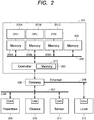
- FIG. 2 is a diagram showing an example of the configuration of the communication apparatus 101.
- the communication device 101 includes CPU201A, 201B, and 201C (hereinafter collectively referred to as "CPU201"), memories 202A, 202B, and 202C (hereinafter collectively referred to as “memory 202 "), a controller 203, a bus 204, and a memory 205.
- the communication device 101 is connected to a CAN (Controller Area Network) 207 and an Ethernet (registered trademark) 208 via gateways 206. Further, the communication device 101 is connected to the powertrain 209, the chassis 210, and the sensors 211 via a CAN207. The communication device 101 is connected to LiDAR212 via the Ethernet 208.
- CAN Controller Area Network
- Ethernet registered trademark
- the configuration of FIG. 2 is an example, and the configuration of the communication apparatus 101 is not limited to this.
- the number of CPU201 and memories 202 may be one, two, or four or more.
- the power train 209 and the sheath 210 and the sensor 211 may be connected to the easer net 208, and LiDAR212 may be connected to CAN207.
- any device other than the powertrain 209, chassis 210, sensors 211, and LiDAR212 may communicate with the communication device 101.
- CPU201 is associated with the memory 202, and CPU201A, 201B, and 201C process the data stored in the memories 202A, 202B, and 202C, respectively.
- the memory 202 is implemented by a random access memory (Random Access Memory) that stores data received from the controller 203 via the bus 204.
- the memories 202 may be DRAM(Dynamic Random Access Memory) or SRAM(Static Random Access Memory).
- the controller 203 divides the frame acquired from the gateway 206 into a plurality of pieces of data.
- the controller 203 transfers the divided data to each memory 202 via the bus 204.
- the controller 203 also includes a memory 213.
- the memory 213 may be external to the controller 203.
- the controller 203 uses the memory 213 as a FIFO (First In First Out memory.
- the memory 205 stores a transfer rule defining an address and the like in the memory of the transfer destination for each data included in each frame.
- the controller 203 determines the data transfer destination by referring to the transfer rule of the memory 205.
- transfer rules may be included in the file descriptor.
- the memory 205 stores a file descriptor chain which is a continuous file descriptor.
- the gateway 206 receives frames from various devices, and transfers the received frames to the communication apparatus 101.
- the gateway 206 transmits the frame received from the communication apparatus 101 to another apparatus.
- the communication device 101 may be SoC (System-on-a-Chip), FPGA (Field Programmable Gate Array, and ASIC(Application Specific Integrated Circuit), or combinations thereof.
- SoC System-on-a-Chip
- FPGA Field Programmable Gate Array
- ASIC Application Specific Integrated Circuit
- FIG. 3 is a diagram showing an example of a signal flowing through a communication path such as the Ethernet 208 of FIG. 2 .
- the signal 301 is a signal for synchronization.
- Signal 302 is a data signal.
- the communication device 101 and the gateways 206 capture the signal 303 detected by the signal 301 during HIGH period as a part of the frame.
- the communication device 101 and the gateway 206 may capture the signal 303 multiple times and process them as a frame.
- FIG. 4 is a diagram showing an example of the type of frame.
- the table 400 includes an example of an Ethernet frame flowing through the Ethernet 208 of FIG. 2 . Each frame is assigned a filtering code.
- the types of data included in the frame include "powertrain data", “chassis data” and "sensor data”. These data may be included in the payload of the frame.
- the frame of the filtering code “a” includes “powertrain data”, “chassis data” and “sensor data” in the payload.
- the frame of the filtering code “c” includes “powertrain data” and “chassis data” in the payload.
- a frame may include one or more data in the payload for each type defined by the filtering code.
- the table 400 describes a block in each column.
- the table 400 may include alphanumeric or binary data instead of blocks.
- FIG. 5 is a diagram showing an example of transfer of data in a frame in the communication apparatus 101.
- the descriptor chain 501 is stored in the memory 205.
- the memory addresses X, Y, and Z are addresses in the respective memories 202.
- the data transferred to the memory addresses X, Y, and Z are processed by CPU201 corresponding to the memory 202.
- each frame includes a plurality of data.
- the frame 503A includes a header A1, a payload B1, and a payload C1.
- the type of frame is assumed to be one.
- the controller 203 transfers a plurality of pieces of data included in the frame to the memory addresses X, Y, and Z.
- the controller 203 refers to the descriptor chain 501 in order to determine the address in the memory of the transfer destination of each data.
- the controller 203 Upon receiving the frame, the controller 203 stores the frame in the memory 213. The data in the memory 213 are processed in the order stored in the memory 213. Next, the controller 203 refers to the descriptor chain 501.
- the descriptor chain 501 includes successive descriptors, and each descriptor includes a transfer rule that specifies how many bytes of data to transfer next to which address.
- the controller 203 refers to the descriptor chain 501 from the head.
- the controller 203 first refers to the first descriptor 502A.
- the descriptor 502A includes a transfer rule "Transfer 20 bytes to address X". Therefore, the controller 203 acquires the 20-byte data "header A1 (20 bytes)" from the memory 213 and transfers it to the memory address X.
- the controller 203 stores the transfer result in the descriptor 502A.
- the transfer result may also include error information.
- the controller 203 refers to the second descriptor 502B.
- the descriptor 502B includes a transfer rule "transfer 50 bytes to address Y". Therefore, the controller 203 acquires the 50-byte data "payload B1 (50 bytes)" from the memory 213 and transfers it to the memory address Y. The controller 203 stores the transfer result in the descriptor 502B.
- the controller 203 refers to the third descriptor 502C.
- the descriptor 502C includes a transfer rule "transfer 80 bytes to address Z". Therefore, the controller 203 acquires 80-byte data "payload C1 (80 bytes)" from the memory 213, and transfers the data to the memory address Z. The controller 203 stores the transfer result in the descriptor 502C.
- controller 203 sequentially refers to the descriptor, and transfers the data in the frames 503B and 503C to any one of the memory addresses X, Y, and Z.
- the controller 203 sequentially refers to the descriptors from the top of the descriptor chain 501, and can determine the number of descriptors to be referred to by checking the transfer result of each descriptor. For example, if the descriptor 502A includes the transfer result "successful writing of 20 bytes of data to the memory address X" and the transfer result of the descriptor 502B is not input, the controller 203 may refer to the descriptor 502B.
- the controller 203 transfers the data included in the received frame to each memory 202 in accordance with the transfer rule defined in the descriptor.
- the transfer using the descriptor is based on the assumption that the frame size corresponding to the descriptor chain 501 is fixed. Therefore, if the controller 203 receives a missing frame of data, a problem may occur. Next, a problem in the case where the controller 203 receives a frame in which data is lost will be described.
- FIG. 6 is a diagram showing an example of transfer of data in a missing frame in the communication apparatus 101. Similar to the illustration of FIG. 5 , descriptor chain 501 is stored in memory 205. The memory addresses X, Y, and Z are addresses in the respective memories 202. The data transferred to the memory addresses X, Y, and Z are processed by CPU201 corresponding to the memory 202.
- the controller 203 receives the frames 603A, 503B, and 503C. It is assumed that the frame 603A is missing and does not include the payload C1 that should be originally included. For the sake of simplicity, it is assumed that the type of frame is one.
- the controller 203 Upon receiving the frame, the controller 203 stores the frame in the memory 213. Next, the controller 203 refers to the descriptor chain 501.
- the controller 203 refers to the descriptor chain 501 from the head.
- the controller 203 refers to the descriptor 502A, acquires the 20-byte data "header A1 " from the memory 213, and transfers the data to the memory address X.
- the controller 203 refers to the descriptor 502B, acquires the 50-byte data "payload B1 " from the memory 213, and transfers it to the memory address Y.
- the controller 203 refers to the descriptor 502C, acquires 80-byte data "payload C1 " from the memory 213, and transfers it to the memory address Z. However, since the payload C1 of the frame 603A is missing, the data acquired next by the controller 203 from the memory 213 becomes the data of the frame 503B.
- the controller 203 cannot detect that the payload C1 is missing. Therefore, the controller 203 acquires "header A2 (20 bytes)", “payload B2 (50 bytes)” and “payload C2 (10 bytes)” as 80-byte data from the memory 213 according to the transfer rule "transfer 80 bytes to address Z" of the descriptor 502C, and transfers them to the memory address Z. As a result, unexpected data is transferred to the memory address Z. The controller 203 cannot detect that a shift has occurred in the transferred data. Therefore, after that, the controller 203 continues the transfer of the data of each frame while the data acquired from the memory 213 is shifted.
- the descriptor according to the present embodiment includes a final data flag capable of determining whether or not the data to be transferred next is the final data of the frame, thereby realizing the detection of the deviation of the data by the controller 203.
- a final data flag capable of determining whether or not the data to be transferred next is the final data of the frame, thereby realizing the detection of the deviation of the data by the controller 203.
- FIG. 7 is a diagram showing an example of transfer of data in a frame using the last data flag in the communication apparatus 101.
- the descriptor corresponding to the last data of the frame includes the "last data flag 710 ".
- descriptors 502C, 502D, and 502E include a "last data flag 710 ".
- descriptor chain 501 is stored in memory 205.
- the memory addresses X, Y, and Z are addresses in the respective memories 202.
- the data transferred to the memory addresses X, Y, and Z are processed by CPU201 corresponding to the respective memories.
- controller 203 receives frames 703A, 703B, and 703C. For the sake of simplicity, it is assumed that the type of frame is one. Upon receiving the frame, the controller 203 stores the frame in the memory 213. Next, the controller 203 refers to the descriptor chain 501.
- the controller 203 refers to the descriptor chain 501 from the head. First, the controller 203 refers to the descriptor 502A and confirms that the descriptor 502A does not include the "last data flag 710 ". Next, the controller 203 determines whether or not the data to be acquired from the memory 213 (hereinafter referred to as "next data") is the last data of the frame.
- the controller 203 transfers the next data to the memory address X, and stores the normal transfer result in the descriptor 502A.
- the controller 203 suspends the transfer of the data, and stores the transfer result including the error in the descriptor 502A.
- the controller 203 adds judgment information indicating the head or the end of the frame before and after the frame 503, and stores the judgment information in the memory 213.
- the controller 203 may add both the judgment information indicating the start of the frame and the judgment information indicating the end of the frame before and after the frame 503, and may store the result in the memory 213.
- the controller 203 counts the size of data input to and output from the memory 213. Therefore, the controller 203 can detect whether or not the next data is the last data of the frame by checking whether or not the determination information is included at the end of the next data. Further, the controller 203 can compare the size of the transfer data defined in the transfer rule of the descriptor with the size of the next data to determine whether or not the last data is missing.
- controller 203 refers to the descriptor 502B and confirms that the descriptor 502A does not include the "last data flag 710 ". Next, the controller 203 determines whether or not the next data is the last data of the frame.
- the controller 203 transfers the next data to the memory address Y, and stores the normal transfer result in the descriptor 502B. If the next data is the last data of the frame, the controller 203 suspends the transfer of the data and stores the transfer result including the error in the descriptor 502B.
- controller 203 refers to the descriptor 502C and confirms that the descriptor 502A includes the "last data flag 710 ". Next, the controller 203 determines whether or not the next data is the last data of the frame.
- the controller 203 transfers the data to the memory address Z and stores the normal transfer result in the descriptor 502C. If the next data is not the last data of the frame or the size of the next data is not normal, the controller 203 suspends the transfer of the data and stores the transfer result including the error in the descriptor 502C.
- the controller 203 may determine that the size of the final data is normal when the size of the final data matches the size of the transfer data defined in the transfer rule of the descriptor 502C.
- the controller 203 may determine that the size of the final data is normal when the size of the final data is within the size of the transfer data defined by the transfer rule of the descriptor 502C. Since the controller 203 counts the size of the data to be input and output to the memory 213, it is possible to calculate the size of the final data in conjunction with the determination information.
- the next data includes the determination information at the end, and the size of the next data is 80 bytes.
- the controller 203 can detect the loss of the frame without fail because the next data includes the determination information when the controller 203 refers to the descriptors 502A and 502B or the size of the next data is not normal when the controller 203 refers to the descriptor 502C.
- the controller 203 stores an error in the descriptor when a frame loss is detected, but in some aspects, the controller 203 may generate error interrupt signals to interrupt CPU201 process. The controller 203 may execute both of these processes.
- the controller 203 can detect a loss of data in units of frames without fail. As a result, the communication device 101 does not require to allocate CPU201 resources for error-detection processing, and the processing performance of the communication apparatus 101 is improved.
- FIG. 8 is a diagram showing an example of a more detailed configuration of the communication apparatus 101.
- the communication device 101 includes an Ethernet PHY801, a media access controller 802, filters 803, memories 804 and 806, a memory controller 805, a bus 808, memories 809A, 809B, and 809C (hereinafter collectively referred to as "memory 809 "), CPU810A, 810B, and 810C (hereinafter collectively referred to as "CPU810"), and a memory 811.
- the communication device 101 transmits and receives a plurality of types of frames, and causes CPU810 to process data included in the frames in a distributed manner.
- the Ethernet PHY801, the media access controller 802, the filters 803, the memories 804 and 806, and the memory control unit 805 correspond to the controller 203.
- the memory control unit 805 uses the memories 804 and 806 as FIFO memories.
- the memory 811 includes a plurality of descriptor chains 812A, 812B, 812C, 812D (hereinafter collectively referred to as "descriptor chains 812 "). Unlike the examples of FIGS. 5 to 7 , the communication apparatus 101 receives a plurality of types of frames. Each descriptor chain 812 is assigned to a respective type of frame.
- the Ethernet PHY801 transmits and receives signals on the Ethernet.
- the media access controller 802 converts the signals received by the Ethernet PHY801 into a frame format and transmits the frame format to the filters 803.
- the Ethernet PHY801 and Media Access Controller 802 processes the signals and data of the network interface layers of the so-called TCP/IP(Transmission Control Protocol/Internet Protocol).
- TCP/IP Transmission Control Protocol/Internet Protocol
- the Ethernet PHY801 and the media access controller 802 are collectively referred to as a communication unit 813.
- the filter 803 determines the type of the received frame.
- the filter 803 transmits the filtering code and the address of the descriptor chain corresponding to the filtering code to the memory control unit 805 based on the type of the frame.
- the filter 803 transmits the frame to the memory control unit 805.
- the filter 803 may transmit only the frame and the address of the descriptor chain to the memory control unit 805.
- the memory control unit 805 may acquire the filtering code from the filter 803, and the memory control unit 805 may determine the address of the descriptor chain corresponding to the filtering code based on the filtering code.
- filter 803 may determine the filtering code from any of the data contained in the frame size, header, and payload. Also, in some aspects, for example, the filter 803 may store the table 400 and determine the filter and select the filtering code based on the table 400. In this case, the filter 803 stores the respective addresses of the descriptor chains 812 associated with the respective filtering codes in the table 400.
- the memory 806 temporarily stores the frame received by the communication apparatus 101. Upon receiving a plurality of frames, the memory control unit 805 sequentially stores the frames in the memory 806 as temporary data 807. The memory control unit 805 counts the size of data input to and output from the memory 806. The frame stored in the memory 806 is divided into a plurality of pieces of data by the memory control unit 805, and further allocated to any one of the memories 809. The memory 804 temporarily stores a frame transmitted by the communication apparatus 101.
- the memory control unit 805 stores the frame in the memory 806 in addition to the judgment information indicating that the frame is the head or the end before and after the frame. When a plurality of frames are received, the memory control unit 805 similarly adds determination information to each frame and stores the result in the memory 806. In one aspect, the memory controller 805 may store the positions of the head and the tail of a frame in the memory 806 as determination information in a register (not shown). In this case, when acquiring the data from the memory 806, the memory control unit 805 can determine whether or not the data acquired from the memory 806 is the last data of the frame by referring to the determination information of the register.
- the memory control unit 805 refers to the address of the descriptor chain corresponding to the filtering code, and acquires the transfer rule. Based on the acquired transfer rule, the memory control unit 805 acquires data of the number of bytes defined in the transfer rule from the memory 806.
- the memory control unit 805 transfers the data acquired from the memory 806 to one of the transfer destination memories 809 defined in the transfer rule. Finally, the memory control unit 805 stores the transfer result in the referenced descriptor.
- the memory controller 805 may be a DMAC (Direct Memory Access Controller.
- the bus 808 interconnects the memory control unit 805, the memory 809, and the memory 811.
- the memory control unit 805 communicates with these memories 809 and 811 via the bus 808.
- Each of the memories 809 is a RAM, and stores data allocated from the memory control unit 805.
- CPU810 is allocated to any of the memories 809.
- CPU810 processes the data stored in the memory 809.
- the memory 811 stores a plurality of descriptor chains 812.
- a descriptor chain 812 is associated with each frame filtering code.
- descriptor chains 812A, 812B, 812C, 812D are associated with filtering codes "a, b, c, d", respectively.
- the memory control unit 805 can distribute the data obtained by dividing the frame into a plurality of frames to each of the memories 809, and distribute the distributed data to CPU810.
- any of CPU910 may execute programs for writing the descriptor chain 812 in the memory 911.
- the communication device 101 may include a ROM (Read Only Memory) (not shown) such as a flash memory for storing the programs.
- the filter 803 determines the type of the frame
- the memory control unit 805 allocates data to each memory 812 by referring to the descriptor chain 812
- CPU810 distributes the data allocated to each memory 809.
- FIG. 9 is a diagram showing an example of communication processing of the communication apparatus 101. With reference to FIG. 9 , the processing at the time of receiving a frame by the communication apparatus 101 in an environment in which a plurality of types of frames are transmitted and received will be described.
- step S905 the communication unit 813 receives signals.
- Communication unit 813 may receive signals from appliances such as, for example, powertrain 209, chassis 210, sensors 211, and a LiDAR212.
- the communication unit 813 converts the received signal into a frame format, and transmits the frame to the filter 803.
- the frames may be in the form of TCP/IP packets or may follow any other format.
- the filter 803 analyzes the received frame and determines the type of the frame.
- the frame may include a correspondence table, not shown, of the filtering code and the address of the descriptor chain 812 corresponding to the filtering code.
- the correspondence table may be obtained by adding the address of the descriptor chain 812 to the table 400.
- the filter 803 determines the filtering code from any of the size of the frame, the header, and the data included in the payload, and acquires the address of the descriptor chain 812 from the correspondence table.
- step S920 the filter 803 transmits the frame to the memory control unit 805.
- step S925 the filter 803 transmits the frame filtering code and the address of the descriptor chain 812 corresponding to the filtering code to the memory control unit 805.
- step S930 the memory control unit 805 temporarily stores the received frame in the memory 806. At this time, the memory control unit 805 adds the judgment information indicating the head or the end of the frame before and after the frame, and stores the frame in the memory 806. Alternatively, the memory control unit 805 may store the positions of the head and the tail of the frame in the memory 806 as the determination information in the register.
- step S935 the memory control unit 805 refers to the addresses of the descriptor chains 812 received from the filters 803.
- the address of the descriptor chain 812 received from the filter 803 is the head address of one of the descriptor chains 812A, 812B, 812C, and 812D.
- the address of the descriptor chain 812 received from the filters 803 in the step S935 is the head address of the descriptor chain 812A.
- the memory control unit 805 acquires the transfer rule of the first "descriptor 1-1 " of the descriptor chain 812A.
- step S940 the memory control unit 805 determines whether or not "descriptor 1-1 " includes the last data flag.
- the memory control unit 805 determines whether or not the next data, i.e., the data acquired from the memory 806, is the last data of the frame based on whether or not the next data includes the determination information.
- the memory control unit 805 when the next data is the last data of the frame, the memory control unit 805 refers to the size of the data defined in the transfer rule, and determines whether or not the size of the next data is equal to or smaller than the size of the data defined in the transfer rule. When the size of the next data is equal to or smaller than the size of the data specified by the transfer rule, the memory control unit 805 determines that the next data is normal final data, and shifts the control to step S945.
- the memory control unit 805 determines that the next data is abnormal, and performs predetermined error processing. Note that the memory control unit 805 may determine whether or not the next data is normal based on whether or not the size of the data defined in the transfer rule matches the size of the next data. Since the memory control unit 805 counts the size of data to be input/output to/from the memory 806, the memory control unit 805 can calculate the size of the next data from the determination information of the next data and the count number when the next data is taken out from the memory 806.
- the memory control unit 805 performs error processing.
- the memory control unit 805 may store a transfer result including an error in the "descriptor 1-1 ", may output an error interrupt signal, or may execute both of these processes.
- step S945 the memory control unit 805 stores the following data in the addresses in the memory 809A defined by the "descriptor 1-1 ".
- the subsequent data stored in the memory 809A is processed by CPU810A.
- step S950 the memory control unit 805 stores the transfer result of the next data in the "descriptor 1-1 ".
- the memory control unit 805 shifts the control to the step S930.
- step S955 the memory control unit 805 advances the referenced descriptor by one in the descriptor chain 812. In step S955, the memory control unit 805 acquires the transfer rules of the "descriptor 1-2 ".
- step S960 the memory control unit 805 determines whether or not the "descriptor 1-2 " includes the last data flag. The memory control unit 805 determines whether or not the next data is the last data of the frame.
- the memory control unit 805 when the next data is the last data of the frame, the memory control unit 805 refers to the size of the data defined in the transfer rule, and determines whether or not the size of the next data is equal to or smaller than the size of the data defined in the transfer rule. When the size of the next data is equal to or smaller than the size of the data specified by the transfer rule, the memory control unit 805 determines that the next data is normal final data, and shifts the control to step S965.
- the memory control unit 805 determines that the next data is abnormal and performs error processing. Note that the memory control unit 805 may determine whether or not the next data is normal based on whether or not the size of the data defined in the transfer rule matches the size of the next data.
- the memory control unit 805 performs error processing.
- the memory control unit 805 may store a transfer result including an error in the "descriptor 1-2 ", may output an error interrupt signal, or may execute both of these processes.
- step S965 the memory control unit 805 stores the following data in the addresses in the memory 809B defined by the "descriptor 1-2 ".
- the subsequent data stored in the memory 809B is processed by CPU810B.
- step S970 the memory control unit 805 stores the transfer result of the next data in the "descriptor 1-2 ".
- the memory control unit 805 shifts the control to the step S930.
- step S975 the memory control unit 805 advances the referenced descriptor by one in the descriptor chain 812. In step S975, the memory control unit 805 acquires the transfer rules of the "descriptor 1-3 ".
- step S980 the memory control unit 805 determines whether or not the "descriptor 1-3 " includes the last data flag. The memory control unit 805 determines whether or not the next data is the last data of the frame.
- the memory control unit 805 when the next data is the last data of the frame, the memory control unit 805 refers to the size of the data defined in the transfer rule, and determines whether or not the size of the next data is equal to or smaller than the size of the data defined in the transfer rule. When the size of the next data is equal to or smaller than the size of the data specified by the transfer rule, the memory control unit 805 determines that the next data is normal final data, and shifts the control to step S965.
- the memory control unit 805 determines that the next data is abnormal and performs error processing. Note that the memory control unit 805 may determine whether or not the next data is normal based on whether or not the size of the data defined in the transfer rule matches the size of the next data.
- the memory control unit 805 performs error processing.
- the memory control unit 805 may store a transfer result including an error in the "descriptor 1-3 ", may output an error interrupt signal, or may execute both of these processes.
- step S985 the memory control unit 805 stores the following data in the addresses in the memory 809C defined by the "descriptors 1-3 ".
- the subsequent data stored in the memory 809C is processed by CPU810C.
- step S990 the memory control unit 805 stores the transfer result of the next data in the "descriptor 1-3 ".
- the memory control unit 805 shifts the control to the step S930.
- the memory control unit 805 allocates all the data included in the frame to the memory 809 by the processes from step S935 to step S990.
- the memory control unit 805 executes the processing of steps S935 to S990 in units of frames. For example, it is assumed that the communication apparatus 101 receives "frame A” and "frame B". Filter 803 sends "frame A” and "frame B” to memory 806. Further, the filter 803 transmits "address A of the descriptor chain 812 " to the memory control unit 805 based on the filtering code of "frame A”. The filter 803 transmits "address B of the descriptor chain 812 " to the memory control unit 805 based on the filtering code of "frame B".
- the memory control unit 805 stores "frame A” and "frame B” in the memory 806. Then, the memory control unit 805 determines the descriptor chain 812 to be referred to based on the "address A of the descriptor chain 812 ". Next, the memory control unit 805 executes the processes after S935 of steps until the final data of the "frame A" is acquired.
- the memory control unit 805 After allocating all the data included in the "frame A" to the memory 809, the memory control unit 805 determines the descriptor chain 812 to be referred to based on the "address B of the descriptor chain 812 ". After that, the memory control unit 805 similarly executes the processes of step S935 and subsequent steps until the memory control unit 805 acquires the final data of the "frame B".
- the memory control unit 805 adds judgment information indicating the head or the end of the frame before and after the frame, and stores the judgment information in the memory 806.
- the memory control unit 805 may store the positions of the head and the tail of the frame in the memory 806 as the determination information in the register.
- the memory control unit 805 counts the size of data to be input/output to/from the memory 806, and stores the data in the memory 806. Therefore, the memory control unit 805 can determine whether or not the next data is the normal last data of the frame by checking whether or not the determination information is included at the end of the next data and checking the size of the next data.
- the communication apparatus 101 can transmit and receive data at any time.
- the memory control unit 805 may receive the message of the step S920 and the step S925 even while executing the process after the step S930.
- FIG. 10 is a diagram showing an example of the format of the descriptor 1000.
- the transfer rule according to the present embodiment includes data defined by the descriptor 1000.
- the descriptor 1000 includes a DT (Descriptor Type), a DIE (Descriptor Interrupt Enable), an MSC (MAC Status Code), a PS (Padding Selection), an EI (Error Indication), a TR (Truncation Indication), a DS (Data Size), a FIN (Final part of Rx-frame), a JDS (Just Data Size), and a DPTR (Data Pointer.
- the DT represents completion/incomplete processing, error, and other states defined by the descriptor 1000.
- the DT may include type information of data to be processed.
- the DIE represents a setting for enabling/disabling an interrupt in a transfer process defined by the descriptor 1000.
- the MSC represents an error code received from the media access controller 802.
- PS represents data for making frames less than the minimum standard size a prescribed size.
- EI represents error information at the time of data transfer.
- TR represents information indicating that the frame has been discarded due to a reception error or the like.
- the FIN represents information indicating that the descriptor 1000 is a descriptor for processing the last data of the divided frame.
- JDS represents a flag for error determination of the last data of a frame.
- the JDS error determination flag may include, for example, the following two types. (Error judgment 1) "If the size of the last data is within the size specified in DS, it is judged that it is normal, and if not, it is judged that it is an error”. (Error determination 2) "If the size of the final data matches the size specified in the DS, it is determined that the data is normal, and if not, it is determined that the data is in error.”
- DPTR refers to the addresses in the memories to which the data is to be transferred.
- the memory control unit 805 refers to DPTR and executes a process of "transferring subsequent data to addresses in the memory defined by DPTR". Note that the format of the descriptor 1000 shown in FIG. 10 is an example, and the items that can be set by the descriptor 1000 are not limited to these.
- the memory control unit 805 can immediately detect an error on a frame-by-frame basis by referring to the last data flag set in the descriptor. As a result, the communication device 101 does not require to allocate CPU810 resources for error-detection processing, and the processing performance of the communication apparatus 101 is improved.
- the second embodiment differs from the first embodiment described above in that one descriptor includes a plurality of transfer rules for data included in a frame.
- the hardware configuration of the communication device 101 according to the second embodiment is the same as that of the communication apparatus 101 of the first embodiment. Therefore, description of the same configuration will not be repeated.
- FIG. 11 is a diagram showing an example of the format of the descriptor 1100.
- the transfer rule according to the present embodiment includes data defined by the descriptor 1100.
- the descriptor 1100 includes DTs, DIEs, MSCs, PSs, EIs, TRs, DSs, and DPTR as many as the number of data in a frame.
- the descriptor 1100 shown in FIG. 11 corresponds to a frame including three pieces of data.
- descriptor 1100 may include any number of two or more data transfer rules.
- the memory control unit 805 can reduce the number of references to the descriptor chain 812.
- the case where the frame includes three pieces of data will be described as an example.
- the memory control unit 805 needs to refer to the descriptor chain 812 three times in order to transfer all the data in the frame.
- the memory control unit 805 since the descriptor 1100 includes three data transfer rules, the memory control unit 805 only needs to refer to the descriptor chain 812 once in order to transfer all the data in the frame. Therefore, in the transfer processing using the descriptor 1100, the memory control unit 805 can omit the step S955 and the step S975 in the processing of FIG. 9 . In step S955,S970,S990, the memory control unit 805 stores the transfer result in the same descriptor.
- the memory control unit 805 can quickly detect a frame loss as compared with the case of using the descriptor 1000 according to the first embodiment.
- the case where the frame includes three pieces of data will be described as an example.
- the memory control unit 805 refers to the descriptor chain 812 once to acquire transfer rules for all data included in the frame.
- the memory control unit 805 can obtain information on the number of data included in the frame and the size of each data based on the transfer rule.
- the memory control unit 805 can determine whether or not the next data acquired from the memory 806 is the head data and the last data by using the determination information added to the frame.
- the memory control unit 805 can determine that a loss has occurred in the data and output an error.
- the memory control unit 805 may store a transfer result including an error in the descriptor 1100, may output an error interrupt signal, or may execute both of these processes.
- the memory control unit 805 can reduce the number of reference times of the descriptor chain by referring to the descriptor defining the transfer rule for a plurality of data included in the frame, and can detect the loss of the frame at an early stage.
- the third embodiment differs from the first and second embodiments described above in that the descriptor includes position information in a frame of data to be processed.
- the hardware configuration of the communication apparatus 101 according to the third embodiment is the same as that of the communication apparatuses 101 of the first and second embodiments. Therefore, description of the same configuration will not be repeated.
- FIG. 12 is a diagram showing an example of the format of the descriptor 1200.
- the transfer rule according to the present embodiment includes data defined by the descriptor 1200.
- the descriptor 1200 includes DTs, DIEs, MSCs, PSs, EIs, TRs, DSs, SMFs (Start or Middle or Final part of Rx-frame), JDSs, and DPTR.
- the SMF defines a position in a frame of data to be processed.
- the position "Start” means that the data to be processed is the head data of the frame.
- the position “Middle” means that the data to be processed is data at an intermediate position which is neither the head nor the end of the frame.
- the position "Final” means that the data to be processed is the last data of the frame.
- the memory control unit 805 can quickly detect a frame loss as compared with the case of using the descriptor 1000 according to the first embodiment.
- the memory control unit 805 can determine whether the data to be transferred next is the head data, the intermediate data, or the last data in the frame.
- the memory control unit 805 can determine whether or not the next data is the head data and the last data by using the determination information added to the frame.
- the memory control unit 805 can determine that a loss has occurred in the data, and can output an error.
- the memory control unit 805 can determine that a loss has occurred in the data, and can output an error.
- the memory control unit 805 may store a transfer result including an error in a descriptor, may output an error interrupt signal, or may execute both of these processes.
- FIG. 13 is a diagram showing an example of the format of the descriptor 1300.
- the transfer rule according to the present embodiment may include data defined by the descriptor 1300 instead of the descriptor 1200.
- the descriptor 1300 includes DTs, DIEs, MSCs, PSs, EIs, TRs, DSs, and DPTR.
- the descriptor 1300 distinguishes the last data in the frame from other data by changing the value of DT to represent a plurality of types of data.
- the memory control unit 805 can determine whether or not the data to be processed is the last data in the frame by referring to the DT of the descriptor 1300. With the use of the descriptor 1300, the memory control unit 805 can determine that a loss has occurred in the data and output an error when the DT of the transfer rule does not indicate the last data and the next data is the last data of the frame, together with the error determination illustrated in FIG. 9 .
- the memory control unit 805 may store a transfer result including an error in a descriptor, may output an error interrupt signal, or may execute both of these processes. As described above, according to the communication apparatus 101 of the present embodiment, the memory control unit 805 can detect a frame loss at an early stage by referring to the descriptor defining the position in the frame of the data to be processed.
- the fourth embodiment differs from the above-mentioned first to third embodiments in that the frame includes a header code and a tail code of each data included in the frame.
- the hardware configuration of the communication device 101 according to the fourth embodiment is the same as that of the communication apparatus 101 of the first to third embodiments. Therefore, description of the same configuration will not be repeated.
- FIG. 14 is a diagram showing an example of the format of the frame 1400.
- the frame 1400 includes a header code and a tail code before and after all payloads included in the frame 1400.
- the frame 1400 includes payloads B1 and C1, and further includes header codes and tail codes before and after the payloads B1 and C1, respectively.
- the header code and the tail code may include the size of the payload and the identification code.
- the header A1 is a header of the frame 1400.
- the memory control unit 805 can acquire the size of the next data acquired from the memory 806 and the identification information of the payload by referring to the header code and the tail code of the frame 1400. Therefore, when retrieving the next data from the memory 806, the memory control unit 805 can compare the size and identification information of the next data with the size, DT, and the like defined in the transfer rule, and output an error when the type and size of the data do not match.
- FIG. 15 is a diagram showing an example of the format of the frame 1500.
- the frame 1500 is different from the frame 1400 in that an element identification code is added to the payload instead of the header code.
- the memory control unit 805 can acquire the size of the next data acquired from the memory 806 and the identification information of the payload by referring to the element identification code and the tail code of the frame 1500. Therefore, when retrieving the next data from the memory 806, the memory control unit 805 can compare the size and header code of the next data with the size and DT defined in the transfer rule, and output an error when the type and size of the data do not match.
- FIG. 16 is a diagram showing an example of the format of the descriptor 1600.
- the transfer rule according to the present embodiment may include data defined by the descriptor 1600 instead of the descriptor 1000.
- the descriptor 1600 is obtained by adding PEID(Packet Element Identification) to the descriptor 1100.
- PEID is an identification code of the data to be processed, and corresponds to the header code of FIG. 14 and the element identification code of FIG. 15 .
- the descriptor 1600 is referred to by the memory control unit 805 together with the frame 1400 or the frame 1500.
- the memory control unit 805 can acquire the size and identification information of the next data when the next data is retrieved from the memory 806.
- the memory control unit 805 can compare the size and identification information of the next data with the size, DT, and the like defined in the transfer rule of the descriptor 1600, and output an error when the type and size of the data do not coincide with each other.
- the memory control unit 805 can acquire the size and identification information of all the data in the frame by referring to the descriptor 1600. Therefore, the memory control unit 805 can determine whether or not each data in the frame is normal by checking the identification information and the size of the subsequent data acquired from the memory 806 with PEID, the DS, and the like of the descriptor 1600. Therefore, even if some data of a frame is lost, the memory control unit 805 can transfer only other normal data to the memory 809 without deleting all of the frames.
- the memory control unit 805 refers to the header code, the tail code, and the like before and after the payload of the frame. Further, the memory control unit 805 can detect missing frames at an early stage by comparing these header codes and tail codes and the like with DT, PEID, DS, and the like of the descriptor.
Landscapes
- Engineering & Computer Science (AREA)
- Computer Networks & Wireless Communication (AREA)
- Signal Processing (AREA)
- Theoretical Computer Science (AREA)
- Environmental & Geological Engineering (AREA)
- Physics & Mathematics (AREA)
- General Engineering & Computer Science (AREA)
- General Physics & Mathematics (AREA)
- Communication Control (AREA)
Abstract
Description
- The disclosure of Japanese Patent Application No.
2019-072624 filed on April 5, 2019 - The present disclosure relates to a communication device, and can be suitably used, for example, in a communication apparatus of an in-vehicle network.
- In recent years, research and development have been carried out on automatic driving technology for automobiles. In order to cause an automobile to automatically drive, it is necessary to process a large number of frames (hereinafter, data transmitted and received on a network is referred to as "frames") acquired by various sensors and cameras attached to the automobile without delay, and to control the entire automobile.
- Along with the automatic operation of automobiles, a large number of devices are connected to the in-vehicle network, and the frame processed by the communication device increases dramatically, and the amount of data to be processed by the communication device is exceeding the processing capacity of the software of the communication device. Therefore, the communication device includes a plurality of memories and CPUs (Central Processing Unit) in order to process a large amount of data.
- In order to cause each CPU to perform distributed processing, the communication apparatus divides the received frame into a plurality of pieces of data, and transmits each piece of data to a memory corresponding to each CPU. At this time, the communication apparatus divides the frame into a plurality of pieces of data on the assumption that the order and size of the payloads in the frame are fixed for each type of the received frame, and transmits these pieces of data to each memory. Therefore, when a frame received by the communication device is missing, the communication apparatus may transfer unintended data to an unintended memory. If the software of the communication device performs exception processing on all unintended data transfers, the processing becomes very complicated, and there is a possibility that a delay occurs in the data processing. Therefore, it is desirable to transfer data and control errors by hardware.
[Patent Document 1] Japanese Patent Application Publication No.2017-204083 - Regarding the transfer of data, for example,
Patent Document 1 discloses a system in which "when the application program to be executed is switched, DMAC refers to the data for setting the memory region including the area data corresponding to the next application program from the TCM to store the area data to be executed, and transfers the data directly to the register of the MPU to perform memory protection". - According to the art disclosed in
Patent Document 1, error control for frame loss cannot be performed. Therefore, even when a frame loss occurs, the communication apparatus continues processing in a state in which unintended data is transferred to an unintended memory. In order to prevent such a state, each CPU included in the communication apparatus needs to execute exception processing by software, and as a result, the processing capacity of the communication apparatus is lowered. Therefore, there is a need for a technique that provides error control for frame loss. The present disclosure has been made in view of the above-described background, and provides a technique for performing error control for frame loss in some aspects. - Other objects and novel features will become apparent from the description of this specification and the accompanying drawings. According to one embodiment, the communication apparatus includes a receiving unit for receiving a frame including a plurality of data, a first memory for temporarily storing a plurality of data, a second memory for storing a transfer rule of each of the plurality of data, a plurality of third memories to which the plurality of data are respectively allocated, and a memory control unit for allocating each of the plurality of data to each of the plurality of third memories in order from the head thereof. The memory control unit outputs an error when the data acquired from the first memory is not the last data of the frame or the size of the data acquired from the first memory is larger than the size defined by the second data in the case where the second data includes the last data flag.
- According to the above embodiment, the communication apparatus can detect a loss of a frame.
-
-
FIG. 1 is a diagram showing an example of a configuration of an in-vehicle network. -
FIG. 2 is a diagram showing an example of the configuration of thecommunication apparatus 101. -
FIG. 3 is a diagram showing an example of a signal flowing through a communication path such as the Ethernet 208 ofFIG. 2 . -
FIG. 4 is a diagram showing an example of the type of frame. -
FIG. 5 is a diagram showing an example of transfer of data in a frame in thecommunication apparatus 101. -
FIG. 6 is a diagram showing an example of transfer of data in a missing frame in thecommunication apparatus 101. -
FIG. 7 is a diagram showing an example of transfer of data in a frame using the last data flag in thecommunication apparatus 101. -
FIG. 8 is a diagram showing an example of a more detailed configuration of thecommunication apparatus 101. -
FIG. 9 is a diagram showing an example of communication processing of thecommunication apparatus 101. -
FIG. 10 is a diagram showing an example of the format of thedescriptor 1000. -
FIG. 11 is a diagram showing an example of the format of thedescriptor 1100. -
FIG. 12 is a diagram showing an example of the format of thedescriptor 1200. -
FIG. 13 is a diagram showing an example of the format of thedescriptor 1300. -
FIG. 14 is a diagram showing an example of the format of theframe 1400. -
FIG. 15 is a diagram showing an example of the format of theframe 1500. -
FIG. 16 is a diagram showing an example of the format of thedescriptor 1600. - Hereinafter, each embodiment will be described in detail with reference to the drawings. The same or corresponding portions are denoted by the same reference numerals, and description thereof will not be repeated.
-
FIG. 1 is a diagram showing an example of a configuration of an in-vehicle network. The in-vehicle network is configured by connecting a plurality ofcommunication apparatuses 101 to each other. A wide variety of devices such as cameras, radars, LiDAR(Light Detection and Ranging, chassis, and powertrains are connected to eachcommunication device 101, and eachcommunication device 101 processes frames received from these devices. Thecommunication apparatus 101 is connected to an external network and can cooperate with a cloud service. Since thecommunication apparatus 101 needs to process and transfer various data without delay, thecommunication apparatus 101 includes a plurality of CPUs and memories. Thecommunication apparatus 101 further includes a memory control unit that divides the received frame into a plurality of pieces of data and allocates the data to each memory. Next, details of thecommunication apparatus 101 will be described. -
FIG. 2 is a diagram showing an example of the configuration of thecommunication apparatus 101. Thecommunication device 101 includes CPU201A, 201B, and 201C (hereinafter collectively referred to as "CPU201"),memories controller 203, abus 204, and amemory 205. - The
communication device 101 is connected to a CAN (Controller Area Network) 207 and an Ethernet (registered trademark) 208 viagateways 206. Further, thecommunication device 101 is connected to thepowertrain 209, thechassis 210, and thesensors 211 via a CAN207. Thecommunication device 101 is connected to LiDAR212 via theEthernet 208. - Note that the configuration of
FIG. 2 is an example, and the configuration of thecommunication apparatus 101 is not limited to this. In certain aspects, the number of CPU201 and memories 202 may be one, two, or four or more. Also in another aspect, thepower train 209 and thesheath 210 and thesensor 211 may be connected to theeaser net 208, and LiDAR212 may be connected to CAN207. In other aspects, any device other than thepowertrain 209,chassis 210,sensors 211, and LiDAR212 may communicate with thecommunication device 101. - CPU201 is associated with the memory 202, and CPU201A, 201B, and 201C process the data stored in the
memories - The memory 202 is implemented by a random access memory (Random Access Memory) that stores data received from the
controller 203 via thebus 204. In some aspects, the memories 202 may be DRAM(Dynamic Random Access Memory) or SRAM(Static Random Access Memory). - The
controller 203 divides the frame acquired from thegateway 206 into a plurality of pieces of data. Thecontroller 203 transfers the divided data to each memory 202 via thebus 204. Thecontroller 203 also includes amemory 213. In some aspects, thememory 213 may be external to thecontroller 203. Thecontroller 203 uses thememory 213 as a FIFO (First In First Out memory. - The
memory 205 stores a transfer rule defining an address and the like in the memory of the transfer destination for each data included in each frame. Thecontroller 203 determines the data transfer destination by referring to the transfer rule of thememory 205. In certain aspects, transfer rules may be included in the file descriptor. Thememory 205 stores a file descriptor chain which is a continuous file descriptor. - The
gateway 206 receives frames from various devices, and transfers the received frames to thecommunication apparatus 101. Thegateway 206 transmits the frame received from thecommunication apparatus 101 to another apparatus. - In some aspects, the
communication device 101 may be SoC (System-on-a-Chip), FPGA (Field Programmable Gate Array, and ASIC(Application Specific Integrated Circuit), or combinations thereof. -
FIG. 3 is a diagram showing an example of a signal flowing through a communication path such as theEthernet 208 ofFIG. 2 . Thesignal 301 is a signal for synchronization.Signal 302 is a data signal. Thecommunication device 101 and thegateways 206 capture thesignal 303 detected by thesignal 301 during HIGH period as a part of the frame. Thecommunication device 101 and thegateway 206 may capture thesignal 303 multiple times and process them as a frame. -
FIG. 4 is a diagram showing an example of the type of frame. The table 400 includes an example of an Ethernet frame flowing through theEthernet 208 ofFIG. 2 . Each frame is assigned a filtering code. The types of data included in the frame include "powertrain data", "chassis data" and "sensor data". These data may be included in the payload of the frame. - In the table 400, for example, the frame of the filtering code "a" includes "powertrain data", "chassis data" and "sensor data" in the payload. The frame of the filtering code "c" includes "powertrain data" and "chassis data" in the payload. Thus, a frame may include one or more data in the payload for each type defined by the filtering code.
- Note that these data are examples, and a frame may include more types of data. For the sake of visual clarity, the table 400 describes a block in each column. When the
communication device 101 stores the table 400, the table 400 may include alphanumeric or binary data instead of blocks. -
FIG. 5 is a diagram showing an example of transfer of data in a frame in thecommunication apparatus 101. Thedescriptor chain 501 is stored in thememory 205. The memory addresses X, Y, and Z are addresses in the respective memories 202. The data transferred to the memory addresses X, Y, and Z are processed by CPU201 corresponding to the memory 202. - Assume that the
controller 203 receives theframes frame 503A includes a header A1, a payload B1, and a payload C1. For the sake of simplicity, in the illustration ofFIGS. 5 to 7 , the type of frame is assumed to be one. - The
controller 203 transfers a plurality of pieces of data included in the frame to the memory addresses X, Y, and Z. Thecontroller 203 refers to thedescriptor chain 501 in order to determine the address in the memory of the transfer destination of each data. - Upon receiving the frame, the
controller 203 stores the frame in thememory 213. The data in thememory 213 are processed in the order stored in thememory 213. Next, thecontroller 203 refers to thedescriptor chain 501. Thedescriptor chain 501 includes successive descriptors, and each descriptor includes a transfer rule that specifies how many bytes of data to transfer next to which address. - The
controller 203 refers to thedescriptor chain 501 from the head. Thecontroller 203 first refers to thefirst descriptor 502A. Thedescriptor 502A includes a transfer rule "Transfer 20 bytes to address X". Therefore, thecontroller 203 acquires the 20-byte data "header A1 (20 bytes)" from thememory 213 and transfers it to the memory address X. Thecontroller 203 stores the transfer result in thedescriptor 502A. The transfer result may also include error information. - Next, the
controller 203 refers to thesecond descriptor 502B. Thedescriptor 502B includes a transfer rule "transfer 50 bytes to address Y". Therefore, thecontroller 203 acquires the 50-byte data "payload B1 (50 bytes)" from thememory 213 and transfers it to the memory address Y. Thecontroller 203 stores the transfer result in thedescriptor 502B. - Next, the
controller 203 refers to thethird descriptor 502C. Thedescriptor 502C includes a transfer rule "transfer 80 bytes to address Z". Therefore, thecontroller 203 acquires 80-byte data "payload C1 (80 bytes)" from thememory 213, and transfers the data to the memory address Z. Thecontroller 203 stores the transfer result in thedescriptor 502C. - Similarly, the
controller 203 sequentially refers to the descriptor, and transfers the data in theframes - The
controller 203 sequentially refers to the descriptors from the top of thedescriptor chain 501, and can determine the number of descriptors to be referred to by checking the transfer result of each descriptor. For example, if thedescriptor 502A includes the transfer result "successful writing of 20 bytes of data to the memory address X" and the transfer result of thedescriptor 502B is not input, thecontroller 203 may refer to thedescriptor 502B. - As described above, the
controller 203 transfers the data included in the received frame to each memory 202 in accordance with the transfer rule defined in the descriptor. The transfer using the descriptor is based on the assumption that the frame size corresponding to thedescriptor chain 501 is fixed. Therefore, if thecontroller 203 receives a missing frame of data, a problem may occur. Next, a problem in the case where thecontroller 203 receives a frame in which data is lost will be described. -
FIG. 6 is a diagram showing an example of transfer of data in a missing frame in thecommunication apparatus 101. Similar to the illustration ofFIG. 5 ,descriptor chain 501 is stored inmemory 205. The memory addresses X, Y, and Z are addresses in the respective memories 202. The data transferred to the memory addresses X, Y, and Z are processed by CPU201 corresponding to the memory 202. - Assume that the
controller 203 receives theframes frame 603A is missing and does not include the payload C1 that should be originally included. For the sake of simplicity, it is assumed that the type of frame is one. Upon receiving the frame, thecontroller 203 stores the frame in thememory 213. Next, thecontroller 203 refers to thedescriptor chain 501. - The
controller 203 refers to thedescriptor chain 501 from the head. Thecontroller 203 refers to thedescriptor 502A, acquires the 20-byte data "header A1 " from thememory 213, and transfers the data to the memory address X. Next, thecontroller 203 refers to thedescriptor 502B, acquires the 50-byte data "payload B1 " from thememory 213, and transfers it to the memory address Y. - Next, the
controller 203 refers to thedescriptor 502C, acquires 80-byte data "payload C1 " from thememory 213, and transfers it to the memory address Z. However, since the payload C1 of theframe 603A is missing, the data acquired next by thecontroller 203 from thememory 213 becomes the data of theframe 503B. - The
controller 203 cannot detect that the payload C1 is missing. Therefore, thecontroller 203 acquires "header A2 (20 bytes)", "payload B2 (50 bytes)" and "payload C2 (10 bytes)" as 80-byte data from thememory 213 according to the transfer rule "transfer 80 bytes to address Z" of thedescriptor 502C, and transfers them to the memory address Z. As a result, unexpected data is transferred to the memory address Z. Thecontroller 203 cannot detect that a shift has occurred in the transferred data. Therefore, after that, thecontroller 203 continues the transfer of the data of each frame while the data acquired from thememory 213 is shifted. - Conventionally, exceptional processes of programs executed by CPU201 detect a deviation of data caused by a loss of a frame, and restore the data. However, this exception processing is complicated and may cause a decrease in the execution speed of the program. Therefore, it is desirable to detect the deviation of the data without using the programs executed by CPU201.
- In order to solve the above-mentioned problems, the descriptor according to the present embodiment includes a final data flag capable of determining whether or not the data to be transferred next is the final data of the frame, thereby realizing the detection of the deviation of the data by the
controller 203. Referring toFIG. 7 , the operation of thecommunication apparatus 101 when the descriptor includes the final data flag will be described. -
FIG. 7 is a diagram showing an example of transfer of data in a frame using the last data flag in thecommunication apparatus 101. In thedescriptor chain 501 according to the present embodiment, the descriptor corresponding to the last data of the frame includes the "last data flag 710 ". In the example shown inFIG. 7 ,descriptors last data flag 710 ". - Similar to the illustration of
FIG. 5 ,descriptor chain 501 is stored inmemory 205. The memory addresses X, Y, and Z are addresses in the respective memories 202. The data transferred to the memory addresses X, Y, and Z are processed by CPU201 corresponding to the respective memories. - In one aspect,
controller 203 receivesframes controller 203 stores the frame in thememory 213. Next, thecontroller 203 refers to thedescriptor chain 501. - The
controller 203 refers to thedescriptor chain 501 from the head. First, thecontroller 203 refers to thedescriptor 502A and confirms that thedescriptor 502A does not include the "last data flag 710 ". Next, thecontroller 203 determines whether or not the data to be acquired from the memory 213 (hereinafter referred to as "next data") is the last data of the frame. - If the next data is not the last data of the frame, the
controller 203 transfers the next data to the memory address X, and stores the normal transfer result in thedescriptor 502A. When the next data is the last data of the frame, since the contents of thedescriptor 502A do not match the contents of the next data, thecontroller 203 suspends the transfer of the data, and stores the transfer result including the error in thedescriptor 502A. - The
controller 203 adds judgment information indicating the head or the end of the frame before and after the frame 503, and stores the judgment information in thememory 213. In one aspect, thecontroller 203 may add both the judgment information indicating the start of the frame and the judgment information indicating the end of the frame before and after the frame 503, and may store the result in thememory 213. - Further, the
controller 203 counts the size of data input to and output from thememory 213. Therefore, thecontroller 203 can detect whether or not the next data is the last data of the frame by checking whether or not the determination information is included at the end of the next data. Further, thecontroller 203 can compare the size of the transfer data defined in the transfer rule of the descriptor with the size of the next data to determine whether or not the last data is missing. - Next, the
controller 203 refers to thedescriptor 502B and confirms that thedescriptor 502A does not include the "last data flag 710 ". Next, thecontroller 203 determines whether or not the next data is the last data of the frame. - When the next data is not the last data of the frame, the
controller 203 transfers the next data to the memory address Y, and stores the normal transfer result in thedescriptor 502B. If the next data is the last data of the frame, thecontroller 203 suspends the transfer of the data and stores the transfer result including the error in thedescriptor 502B. - Next, the
controller 203 refers to thedescriptor 502C and confirms that thedescriptor 502A includes the "last data flag 710 ". Next, thecontroller 203 determines whether or not the next data is the last data of the frame. - When the next data is the last data of the frame and the size of the next data is normal, the
controller 203 transfers the data to the memory address Z and stores the normal transfer result in thedescriptor 502C. If the next data is not the last data of the frame or the size of the next data is not normal, thecontroller 203 suspends the transfer of the data and stores the transfer result including the error in thedescriptor 502C. - In determining the size of the final data, the
controller 203 may determine that the size of the final data is normal when the size of the final data matches the size of the transfer data defined in the transfer rule of thedescriptor 502C. Thecontroller 203 may determine that the size of the final data is normal when the size of the final data is within the size of the transfer data defined by the transfer rule of thedescriptor 502C. Since thecontroller 203 counts the size of the data to be input and output to thememory 213, it is possible to calculate the size of the final data in conjunction with the determination information. - In the example of
FIG. 7 , when theframe 503A is normal, when thecontroller 203 refers to thedescriptor 502C including the "last data flag 710 ", the next data includes the determination information at the end, and the size of the next data is 80 bytes. - However, when a part of the
frame 503A is missing, thecontroller 203 can detect the loss of the frame without fail because the next data includes the determination information when thecontroller 203 refers to thedescriptors controller 203 refers to thedescriptor 502C. - In this embodiment, the
controller 203 stores an error in the descriptor when a frame loss is detected, but in some aspects, thecontroller 203 may generate error interrupt signals to interrupt CPU201 process. Thecontroller 203 may execute both of these processes. - As described above, since the descriptor corresponding to the last data of the frame has the last frame flag, the
controller 203 can detect a loss of data in units of frames without fail. As a result, thecommunication device 101 does not require to allocate CPU201 resources for error-detection processing, and the processing performance of thecommunication apparatus 101 is improved. -
FIG. 8 is a diagram showing an example of a more detailed configuration of thecommunication apparatus 101. Thecommunication device 101 includes an Ethernet PHY801, amedia access controller 802,filters 803,memories memory controller 805, abus 808,memories memory 811. Thecommunication device 101 transmits and receives a plurality of types of frames, and causes CPU810 to process data included in the frames in a distributed manner. The Ethernet PHY801, themedia access controller 802, thefilters 803, thememories memory control unit 805 correspond to thecontroller 203. Thememory control unit 805 uses thememories - The
memory 811 includes a plurality ofdescriptor chains FIGS. 5 to 7 , thecommunication apparatus 101 receives a plurality of types of frames. Each descriptor chain 812 is assigned to a respective type of frame. - The Ethernet PHY801 transmits and receives signals on the Ethernet. The
media access controller 802 converts the signals received by the Ethernet PHY801 into a frame format and transmits the frame format to thefilters 803. The Ethernet PHY801 andMedia Access Controller 802 processes the signals and data of the network interface layers of the so-called TCP/IP(Transmission Control Protocol/Internet Protocol). Hereinafter, the Ethernet PHY801 and themedia access controller 802 are collectively referred to as acommunication unit 813. Thefilter 803 determines the type of the received frame. Thefilter 803 transmits the filtering code and the address of the descriptor chain corresponding to the filtering code to thememory control unit 805 based on the type of the frame. Thefilter 803 transmits the frame to thememory control unit 805. Thefilter 803 may transmit only the frame and the address of the descriptor chain to thememory control unit 805. Thememory control unit 805 may acquire the filtering code from thefilter 803, and thememory control unit 805 may determine the address of the descriptor chain corresponding to the filtering code based on the filtering code. - In certain aspects,
filter 803 may determine the filtering code from any of the data contained in the frame size, header, and payload. Also, in some aspects, for example, thefilter 803 may store the table 400 and determine the filter and select the filtering code based on the table 400. In this case, thefilter 803 stores the respective addresses of the descriptor chains 812 associated with the respective filtering codes in the table 400. Thememory 806 temporarily stores the frame received by thecommunication apparatus 101. Upon receiving a plurality of frames, thememory control unit 805 sequentially stores the frames in thememory 806 astemporary data 807. Thememory control unit 805 counts the size of data input to and output from thememory 806. The frame stored in thememory 806 is divided into a plurality of pieces of data by thememory control unit 805, and further allocated to any one of the memories 809. Thememory 804 temporarily stores a frame transmitted by thecommunication apparatus 101. - The
memory control unit 805 stores the frame in thememory 806 in addition to the judgment information indicating that the frame is the head or the end before and after the frame. When a plurality of frames are received, thememory control unit 805 similarly adds determination information to each frame and stores the result in thememory 806. In one aspect, thememory controller 805 may store the positions of the head and the tail of a frame in thememory 806 as determination information in a register (not shown). In this case, when acquiring the data from thememory 806, thememory control unit 805 can determine whether or not the data acquired from thememory 806 is the last data of the frame by referring to the determination information of the register. - Next, the
memory control unit 805 refers to the address of the descriptor chain corresponding to the filtering code, and acquires the transfer rule. Based on the acquired transfer rule, thememory control unit 805 acquires data of the number of bytes defined in the transfer rule from thememory 806. - Next, the
memory control unit 805 transfers the data acquired from thememory 806 to one of the transfer destination memories 809 defined in the transfer rule. Finally, thememory control unit 805 stores the transfer result in the referenced descriptor. In one aspect, thememory controller 805 may be a DMAC (Direct Memory Access Controller. - The
bus 808 interconnects thememory control unit 805, the memory 809, and thememory 811. Thememory control unit 805 communicates with thesememories 809 and 811 via thebus 808. Each of the memories 809 is a RAM, and stores data allocated from thememory control unit 805. CPU810 is allocated to any of the memories 809. CPU810 processes the data stored in the memory 809. - The
memory 811 stores a plurality of descriptor chains 812. A descriptor chain 812 is associated with each frame filtering code. For example, referring to table 400,descriptor chains - By referring to the addresses of the descriptor chains 812 received from the
filters 803, thememory control unit 805 can distribute the data obtained by dividing the frame into a plurality of frames to each of the memories 809, and distribute the distributed data to CPU810. - In one aspect, upon activation of the
communication device 101, any of CPU910 may execute programs for writing the descriptor chain 812 in the memory 911. In this instance, thecommunication device 101 may include a ROM (Read Only Memory) (not shown) such as a flash memory for storing the programs. - As described above, in the
communication device 101, thefilter 803 determines the type of the frame, thememory control unit 805 allocates data to each memory 812 by referring to the descriptor chain 812, and CPU810 distributes the data allocated to each memory 809. -
FIG. 9 is a diagram showing an example of communication processing of thecommunication apparatus 101. With reference toFIG. 9 , the processing at the time of receiving a frame by thecommunication apparatus 101 in an environment in which a plurality of types of frames are transmitted and received will be described. - In step S905, the
communication unit 813 receives signals.Communication unit 813 may receive signals from appliances such as, for example,powertrain 209,chassis 210,sensors 211, and a LiDAR212. - In step S910, the
communication unit 813 converts the received signal into a frame format, and transmits the frame to thefilter 803. In certain aspects, the frames may be in the form of TCP/IP packets or may follow any other format. - In step S915, the
filter 803 analyzes the received frame and determines the type of the frame. The frame may include a correspondence table, not shown, of the filtering code and the address of the descriptor chain 812 corresponding to the filtering code. For example, the correspondence table may be obtained by adding the address of the descriptor chain 812 to the table 400. Thefilter 803 determines the filtering code from any of the size of the frame, the header, and the data included in the payload, and acquires the address of the descriptor chain 812 from the correspondence table. - In step S920, the
filter 803 transmits the frame to thememory control unit 805. In step S925, thefilter 803 transmits the frame filtering code and the address of the descriptor chain 812 corresponding to the filtering code to thememory control unit 805. - In step S930, the
memory control unit 805 temporarily stores the received frame in thememory 806. At this time, thememory control unit 805 adds the judgment information indicating the head or the end of the frame before and after the frame, and stores the frame in thememory 806. Alternatively, thememory control unit 805 may store the positions of the head and the tail of the frame in thememory 806 as the determination information in the register. - In step S935, the
memory control unit 805 refers to the addresses of the descriptor chains 812 received from thefilters 803. In the example shown inFIG. 9 , the address of the descriptor chain 812 received from thefilter 803 is the head address of one of thedescriptor chains - It is assumed that the address of the descriptor chain 812 received from the
filters 803 in the step S935 is the head address of thedescriptor chain 812A. Thememory control unit 805 acquires the transfer rule of the first "descriptor 1-1 " of thedescriptor chain 812A. - In step S940, the
memory control unit 805 determines whether or not "descriptor 1-1 " includes the last data flag. Thememory control unit 805 determines whether or not the next data, i.e., the data acquired from thememory 806, is the last data of the frame based on whether or not the next data includes the determination information. - When "Descriptor 1-1 " does not include the last data flag and the next data is not the last data of the frame, the
memory control unit 805 shifts the control to the step S945. - In the case where "descriptor 1-1 " includes the last data flag, when the next data is the last data of the frame, the
memory control unit 805 refers to the size of the data defined in the transfer rule, and determines whether or not the size of the next data is equal to or smaller than the size of the data defined in the transfer rule. When the size of the next data is equal to or smaller than the size of the data specified by the transfer rule, thememory control unit 805 determines that the next data is normal final data, and shifts the control to step S945. - When the size of the next data is larger than the size of the data defined by the transfer rule, the
memory control unit 805 determines that the next data is abnormal, and performs predetermined error processing. Note that thememory control unit 805 may determine whether or not the next data is normal based on whether or not the size of the data defined in the transfer rule matches the size of the next data. Since thememory control unit 805 counts the size of data to be input/output to/from thememory 806, thememory control unit 805 can calculate the size of the next data from the determination information of the next data and the count number when the next data is taken out from thememory 806. - Otherwise, the
memory control unit 805 performs error processing. In the error processing, thememory control unit 805 may store a transfer result including an error in the "descriptor 1-1 ", may output an error interrupt signal, or may execute both of these processes. - In step S945, the
memory control unit 805 stores the following data in the addresses in thememory 809A defined by the "descriptor 1-1 ". The subsequent data stored in thememory 809A is processed by CPU810A. - In step S950, the
memory control unit 805 stores the transfer result of the next data in the "descriptor 1-1 ". When the subsequent data is the last data of the frame, thememory control unit 805 shifts the control to the step S930. - In step S955, the
memory control unit 805 advances the referenced descriptor by one in the descriptor chain 812. In step S955, thememory control unit 805 acquires the transfer rules of the "descriptor 1-2 ". - In step S960, the
memory control unit 805 determines whether or not the "descriptor 1-2 " includes the last data flag. Thememory control unit 805 determines whether or not the next data is the last data of the frame. - In the case where "descriptor 1-2 " includes the last data flag, when the next data is the last data of the frame, the
memory control unit 805 refers to the size of the data defined in the transfer rule, and determines whether or not the size of the next data is equal to or smaller than the size of the data defined in the transfer rule. When the size of the next data is equal to or smaller than the size of the data specified by the transfer rule, thememory control unit 805 determines that the next data is normal final data, and shifts the control to step S965. - When the size of the next data is larger than the size of the data defined in the transfer rule, the
memory control unit 805 determines that the next data is abnormal and performs error processing. Note that thememory control unit 805 may determine whether or not the next data is normal based on whether or not the size of the data defined in the transfer rule matches the size of the next data. - Otherwise, the
memory control unit 805 performs error processing. In the error processing, thememory control unit 805 may store a transfer result including an error in the "descriptor 1-2 ", may output an error interrupt signal, or may execute both of these processes. - In step S965, the
memory control unit 805 stores the following data in the addresses in thememory 809B defined by the "descriptor 1-2 ". The subsequent data stored in thememory 809B is processed by CPU810B. - In step S970, the
memory control unit 805 stores the transfer result of the next data in the "descriptor 1-2 ". When the subsequent data is the last data of the frame, thememory control unit 805 shifts the control to the step S930. - In step S975, the
memory control unit 805 advances the referenced descriptor by one in the descriptor chain 812. In step S975, thememory control unit 805 acquires the transfer rules of the "descriptor 1-3 ". - In step S980, the
memory control unit 805 determines whether or not the "descriptor 1-3 " includes the last data flag. Thememory control unit 805 determines whether or not the next data is the last data of the frame. - In the case where "descriptor 1-3 " includes the last data flag, when the next data is the last data of the frame, the
memory control unit 805 refers to the size of the data defined in the transfer rule, and determines whether or not the size of the next data is equal to or smaller than the size of the data defined in the transfer rule. When the size of the next data is equal to or smaller than the size of the data specified by the transfer rule, thememory control unit 805 determines that the next data is normal final data, and shifts the control to step S965. - When the size of the next data is larger than the size of the data defined in the transfer rule, the
memory control unit 805 determines that the next data is abnormal and performs error processing. Note that thememory control unit 805 may determine whether or not the next data is normal based on whether or not the size of the data defined in the transfer rule matches the size of the next data. - Otherwise, the
memory control unit 805 performs error processing. In the error processing, thememory control unit 805 may store a transfer result including an error in the "descriptor 1-3 ", may output an error interrupt signal, or may execute both of these processes. - In step S985, the
memory control unit 805 stores the following data in the addresses in thememory 809C defined by the "descriptors 1-3 ". The subsequent data stored in thememory 809C is processed by CPU810C. - In step S990, the
memory control unit 805 stores the transfer result of the next data in the "descriptor 1-3 ". When the subsequent data is the last data of the frame, thememory control unit 805 shifts the control to the step S930. - If the number of data included in the frame is three, the
memory control unit 805 allocates all the data included in the frame to the memory 809 by the processes from step S935 to step S990. - In the processing described referring to
FIG. 9 , thememory control unit 805 executes the processing of steps S935 to S990 in units of frames. For example, it is assumed that thecommunication apparatus 101 receives "frame A" and "frame B".Filter 803 sends "frame A" and "frame B" tomemory 806. Further, thefilter 803 transmits "address A of the descriptor chain 812 " to thememory control unit 805 based on the filtering code of "frame A". Thefilter 803 transmits "address B of the descriptor chain 812 " to thememory control unit 805 based on the filtering code of "frame B". - The
memory control unit 805 stores "frame A" and "frame B" in thememory 806. Then, thememory control unit 805 determines the descriptor chain 812 to be referred to based on the "address A of the descriptor chain 812 ". Next, thememory control unit 805 executes the processes after S935 of steps until the final data of the "frame A" is acquired. - After allocating all the data included in the "frame A" to the memory 809, the
memory control unit 805 determines the descriptor chain 812 to be referred to based on the "address B of the descriptor chain 812 ". After that, thememory control unit 805 similarly executes the processes of step S935 and subsequent steps until thememory control unit 805 acquires the final data of the "frame B". - As in the example of
FIG. 7 , thememory control unit 805 adds judgment information indicating the head or the end of the frame before and after the frame, and stores the judgment information in thememory 806. Alternatively, thememory control unit 805 may store the positions of the head and the tail of the frame in thememory 806 as the determination information in the register. Further, thememory control unit 805 counts the size of data to be input/output to/from thememory 806, and stores the data in thememory 806. Therefore, thememory control unit 805 can determine whether or not the next data is the normal last data of the frame by checking whether or not the determination information is included at the end of the next data and checking the size of the next data. - In the processing of
FIG. 9 , thecommunication apparatus 101 can transmit and receive data at any time. For example, thememory control unit 805 may receive the message of the step S920 and the step S925 even while executing the process after the step S930. -
FIG. 10 is a diagram showing an example of the format of thedescriptor 1000. The transfer rule according to the present embodiment includes data defined by thedescriptor 1000. Thedescriptor 1000 includes a DT (Descriptor Type), a DIE (Descriptor Interrupt Enable), an MSC (MAC Status Code), a PS (Padding Selection), an EI (Error Indication), a TR (Truncation Indication), a DS (Data Size), a FIN (Final part of Rx-frame), a JDS (Just Data Size), and a DPTR (Data Pointer. - The DT represents completion/incomplete processing, error, and other states defined by the
descriptor 1000. The DT may include type information of data to be processed. The DIE represents a setting for enabling/disabling an interrupt in a transfer process defined by thedescriptor 1000. The MSC represents an error code received from themedia access controller 802. PS represents data for making frames less than the minimum standard size a prescribed size. - EI represents error information at the time of data transfer. TR represents information indicating that the frame has been discarded due to a reception error or the like. The FIN represents information indicating that the
descriptor 1000 is a descriptor for processing the last data of the divided frame. - JDS represents a flag for error determination of the last data of a frame. The JDS error determination flag may include, for example, the following two types. (Error judgment 1) "If the size of the last data is within the size specified in DS, it is judged that it is normal, and if not, it is judged that it is an error". (Error determination 2) "If the size of the final data matches the size specified in the DS, it is determined that the data is normal, and if not, it is determined that the data is in error." DPTR refers to the addresses in the memories to which the data is to be transferred. The
memory control unit 805 refers to DPTR and executes a process of "transferring subsequent data to addresses in the memory defined by DPTR". Note that the format of thedescriptor 1000 shown inFIG. 10 is an example, and the items that can be set by thedescriptor 1000 are not limited to these. - As described above, according to the
communication apparatus 101 of the present embodiment, thememory control unit 805 can immediately detect an error on a frame-by-frame basis by referring to the last data flag set in the descriptor. As a result, thecommunication device 101 does not require to allocate CPU810 resources for error-detection processing, and the processing performance of thecommunication apparatus 101 is improved. - Next, processing of the
communication apparatus 101 according to the second embodiment will be described. The second embodiment differs from the first embodiment described above in that one descriptor includes a plurality of transfer rules for data included in a frame. The hardware configuration of thecommunication device 101 according to the second embodiment is the same as that of thecommunication apparatus 101 of the first embodiment. Therefore, description of the same configuration will not be repeated. -
FIG. 11 is a diagram showing an example of the format of thedescriptor 1100. The transfer rule according to the present embodiment includes data defined by thedescriptor 1100. Thedescriptor 1100 includes DTs, DIEs, MSCs, PSs, EIs, TRs, DSs, and DPTR as many as the number of data in a frame. Thedescriptor 1100 shown inFIG. 11 corresponds to a frame including three pieces of data. In certain aspects,descriptor 1100 may include any number of two or more data transfer rules. - By using the
descriptor 1100, thememory control unit 805 can reduce the number of references to the descriptor chain 812. The case where the frame includes three pieces of data will be described as an example. - In the case of transfer processing using the
descriptor 1000, since thedescriptor 1000 includes only one data transfer rule, thememory control unit 805 needs to refer to the descriptor chain 812 three times in order to transfer all the data in the frame. - On the other hand, in the case of transfer processing using the
descriptor 1100, since thedescriptor 1100 includes three data transfer rules, thememory control unit 805 only needs to refer to the descriptor chain 812 once in order to transfer all the data in the frame. Therefore, in the transfer processing using thedescriptor 1100, thememory control unit 805 can omit the step S955 and the step S975 in the processing ofFIG. 9 . In step S955,S970,S990, thememory control unit 805 stores the transfer result in the same descriptor. - Further, by using the
descriptor 1100, thememory control unit 805 can quickly detect a frame loss as compared with the case of using thedescriptor 1000 according to the first embodiment. The case where the frame includes three pieces of data will be described as an example. - The
memory control unit 805 refers to the descriptor chain 812 once to acquire transfer rules for all data included in the frame. Thememory control unit 805 can obtain information on the number of data included in the frame and the size of each data based on the transfer rule. When storing the frame in thememory 806, thememory control unit 805 can determine whether or not the next data acquired from thememory 806 is the head data and the last data by using the determination information added to the frame. - Therefore, together with the error determination illustrated in
FIG. 9 , when the data to be transferred next, which is defined in the transfer rule, is not the last data of the frame and the next data is the last data of the frame, thememory control unit 805 can determine that a loss has occurred in the data and output an error. - In the error processing, the
memory control unit 805 may store a transfer result including an error in thedescriptor 1100, may output an error interrupt signal, or may execute both of these processes. - As described above, according to the
communication apparatus 101 of the present embodiment, thememory control unit 805 can reduce the number of reference times of the descriptor chain by referring to the descriptor defining the transfer rule for a plurality of data included in the frame, and can detect the loss of the frame at an early stage. - Next, processing of the
communication apparatus 101 according to the third embodiment will be described. The third embodiment differs from the first and second embodiments described above in that the descriptor includes position information in a frame of data to be processed. The hardware configuration of thecommunication apparatus 101 according to the third embodiment is the same as that of thecommunication apparatuses 101 of the first and second embodiments. Therefore, description of the same configuration will not be repeated. -
FIG. 12 is a diagram showing an example of the format of thedescriptor 1200. The transfer rule according to the present embodiment includes data defined by thedescriptor 1200. Thedescriptor 1200 includes DTs, DIEs, MSCs, PSs, EIs, TRs, DSs, SMFs (Start or Middle or Final part of Rx-frame), JDSs, and DPTR. The SMF defines a position in a frame of data to be processed. The position "Start" means that the data to be processed is the head data of the frame. The position "Middle" means that the data to be processed is data at an intermediate position which is neither the head nor the end of the frame. The position "Final" means that the data to be processed is the last data of the frame. - By using the
descriptor 1200, thememory control unit 805 can quickly detect a frame loss as compared with the case of using thedescriptor 1000 according to the first embodiment. By referring to the IMF included in the transfer rule, thememory control unit 805 can determine whether the data to be transferred next is the head data, the intermediate data, or the last data in the frame. When storing the frame in thememory 806, thememory control unit 805 can determine whether or not the next data is the head data and the last data by using the determination information added to the frame. - Therefore, together with the error determination illustrated in
FIG. 9 , when the position of the data to be transferred next, which is defined by the transfer rules, is "Start" or "Middle", and when the next data is the last data of the frame, thememory control unit 805 can determine that a loss has occurred in the data, and can output an error. - In addition to the error determination illustrated in
FIG. 9 , when the position of the data to be transferred next, which is defined by the transfer rules, is "Middle" or "Final", and when the next data is the head data of the frame, thememory control unit 805 can determine that a loss has occurred in the data, and can output an error. - In the error processing, the
memory control unit 805 may store a transfer result including an error in a descriptor, may output an error interrupt signal, or may execute both of these processes. -
FIG. 13 is a diagram showing an example of the format of thedescriptor 1300. The transfer rule according to the present embodiment may include data defined by thedescriptor 1300 instead of thedescriptor 1200. Thedescriptor 1300 includes DTs, DIEs, MSCs, PSs, EIs, TRs, DSs, and DPTR. - The
descriptor 1300 distinguishes the last data in the frame from other data by changing the value of DT to represent a plurality of types of data. Thememory control unit 805 can determine whether or not the data to be processed is the last data in the frame by referring to the DT of thedescriptor 1300. With the use of thedescriptor 1300, thememory control unit 805 can determine that a loss has occurred in the data and output an error when the DT of the transfer rule does not indicate the last data and the next data is the last data of the frame, together with the error determination illustrated inFIG. 9 . - In the error processing, the
memory control unit 805 may store a transfer result including an error in a descriptor, may output an error interrupt signal, or may execute both of these processes. As described above, according to thecommunication apparatus 101 of the present embodiment, thememory control unit 805 can detect a frame loss at an early stage by referring to the descriptor defining the position in the frame of the data to be processed. - Next, processing of the
communication apparatus 101 according to the fourth embodiment will be described. The fourth embodiment differs from the above-mentioned first to third embodiments in that the frame includes a header code and a tail code of each data included in the frame. The hardware configuration of thecommunication device 101 according to the fourth embodiment is the same as that of thecommunication apparatus 101 of the first to third embodiments. Therefore, description of the same configuration will not be repeated. -
FIG. 14 is a diagram showing an example of the format of theframe 1400. Theframe 1400 includes a header code and a tail code before and after all payloads included in theframe 1400. In the example ofFIG. 14 , theframe 1400 includes payloads B1 and C1, and further includes header codes and tail codes before and after the payloads B1 and C1, respectively. The header code and the tail code may include the size of the payload and the identification code. The header A1 is a header of theframe 1400. Thememory control unit 805 can acquire the size of the next data acquired from thememory 806 and the identification information of the payload by referring to the header code and the tail code of theframe 1400. Therefore, when retrieving the next data from thememory 806, thememory control unit 805 can compare the size and identification information of the next data with the size, DT, and the like defined in the transfer rule, and output an error when the type and size of the data do not match. -
FIG. 15 is a diagram showing an example of the format of theframe 1500. Theframe 1500 is different from theframe 1400 in that an element identification code is added to the payload instead of the header code. - The
memory control unit 805 can acquire the size of the next data acquired from thememory 806 and the identification information of the payload by referring to the element identification code and the tail code of theframe 1500. Therefore, when retrieving the next data from thememory 806, thememory control unit 805 can compare the size and header code of the next data with the size and DT defined in the transfer rule, and output an error when the type and size of the data do not match. -
FIG. 16 is a diagram showing an example of the format of thedescriptor 1600. The transfer rule according to the present embodiment may include data defined by thedescriptor 1600 instead of thedescriptor 1000. Thedescriptor 1600 is obtained by adding PEID(Packet Element Identification) to thedescriptor 1100. - PEID is an identification code of the data to be processed, and corresponds to the header code of
FIG. 14 and the element identification code ofFIG. 15 . Thedescriptor 1600 is referred to by thememory control unit 805 together with theframe 1400 or theframe 1500. - By referring to the
frame 1400 or theframe 1500, thememory control unit 805 can acquire the size and identification information of the next data when the next data is retrieved from thememory 806. Thememory control unit 805 can compare the size and identification information of the next data with the size, DT, and the like defined in the transfer rule of thedescriptor 1600, and output an error when the type and size of the data do not coincide with each other. - Further, the
memory control unit 805 can acquire the size and identification information of all the data in the frame by referring to thedescriptor 1600. Therefore, thememory control unit 805 can determine whether or not each data in the frame is normal by checking the identification information and the size of the subsequent data acquired from thememory 806 with PEID, the DS, and the like of thedescriptor 1600. Therefore, even if some data of a frame is lost, thememory control unit 805 can transfer only other normal data to the memory 809 without deleting all of the frames. - As described above, according to the
communication apparatus 101 of the present embodiment, thememory control unit 805 refers to the header code, the tail code, and the like before and after the payload of the frame. Further, thememory control unit 805 can detect missing frames at an early stage by comparing these header codes and tail codes and the like with DT, PEID, DS, and the like of the descriptor. - Although the invention made by the present inventor has been specifically described based on the embodiment, the present invention is not limited to the above embodiment, and it is needless to say that various modifications can be made without departing from the gist thereof.
Claims (7)
- A data processing device comprising:a receiving circuit configured to receive a communication frame including a plurality of data;a memory control circuit configured to transfer the data to a memory circuit in accordance with transferring rules;wherein, in case of transferring one of the data when a corresponding transferring rule indicates the last data transfer, when the one of the data is the last data of the communication frame and whose size is within the a size prescribed in the corresponding transferring rule, the memory control circuit transfers the one of the data to a corresponding destination of the memory circuit, andwherein, in case of transferring one of the data when the corresponding transferring rule indicates the last data transfer, when the one of the data is not the last data of the communication frame or whose size excesses the size prescribed in the corresponding one of the transferring rules, the memory control circuit output an error detection signal.
- The data processing device according to claim 1, further comprising a rule memory circuit configured to store the transferring rules.
- The data processing device according to claim 1 or 2, further comprising a filtering circuit configured to obtain an identifier from the communication frame,
wherein the memory control circuit obtains the corresponding transferring rule based on the identifier. - The data processing device according to one of claims 1 to 3, further comprising a temporary memory circuit configured to store the plurality of the data before the transfer by the memory circuit.
- The data processing device according to one of claims 1 to 4,
wherein the memory control circuit determines the last data based on footer information stored with the plurality of the data in the temporary memory circuit. - A data transferring method for a communication device, comprising:(a) receiving a communication frame;(b) dividing the communication frame into a plurality of data;(c) obtaining a transferring rule corresponding one of the data to be transferred;(d) determining whether the data to be transferred is the last data;(e) determining a size of the data to be transferred;(f) determining to transfer the data to be transferred or detect an error based on the transferring rule and a determination result of (d) and (e).
- The data transferring method according to claim 6,
wherein the (d) determining is performed based on footer information which is in connection with the plurality of the data.
Applications Claiming Priority (1)
| Application Number | Priority Date | Filing Date | Title |
|---|---|---|---|
| JP2019072624A JP7145117B2 (en) | 2019-04-05 | 2019-04-05 | Communication device |
Publications (2)
| Publication Number | Publication Date |
|---|---|
| EP3719661A1 true EP3719661A1 (en) | 2020-10-07 |
| EP3719661B1 EP3719661B1 (en) | 2021-12-22 |
Family
ID=70110253
Family Applications (1)
| Application Number | Title | Priority Date | Filing Date |
|---|---|---|---|
| EP20167419.9A Active EP3719661B1 (en) | 2019-04-05 | 2020-03-31 | Communication device |
Country Status (4)
| Country | Link |
|---|---|
| US (1) | US11606276B2 (en) |
| EP (1) | EP3719661B1 (en) |
| JP (1) | JP7145117B2 (en) |
| CN (1) | CN111800224A (en) |
Families Citing this family (1)
| Publication number | Priority date | Publication date | Assignee | Title |
|---|---|---|---|---|
| US11758460B1 (en) * | 2021-02-02 | 2023-09-12 | T-Mobile Usa, Inc. | Managing local application connectivity in a multi-network environment |
Citations (6)
| Publication number | Priority date | Publication date | Assignee | Title |
|---|---|---|---|---|
| WO1992006435A1 (en) * | 1990-09-28 | 1992-04-16 | Fujitsu Limited | Message control system in a data communication system |
| US5724391A (en) * | 1995-09-20 | 1998-03-03 | Matsushita Electric Industrial Co., Ltd. | Apparatus for transmission of variable length data |
| EP1414176A2 (en) * | 2002-10-24 | 2004-04-28 | Matsushita Electric Industrial Co., Ltd. | Communication device and communication method immune to burst error, program for executing the method, and computer-readable storage medium storing the program |
| EP2192715A2 (en) * | 2008-12-01 | 2010-06-02 | Fujitsu Limited | System including transmitter and receiver |
| JP2017204083A (en) | 2016-05-10 | 2017-11-16 | 株式会社デンソー | Memory protection system |
| JP2019072624A (en) | 2019-02-25 | 2019-05-16 | 株式会社三洋物産 | Game machine |
Family Cites Families (22)
| Publication number | Priority date | Publication date | Assignee | Title |
|---|---|---|---|---|
| JPH05191456A (en) * | 1992-01-10 | 1993-07-30 | Mitsubishi Electric Corp | Packet relaying method for packet switching network |
| JPH07254909A (en) * | 1994-03-15 | 1995-10-03 | Fujitsu Ltd | Packet transfer equipment |
| US6717910B1 (en) * | 1998-09-30 | 2004-04-06 | Stmicroelectronics, Inc. | Method and apparatus for controlling network data congestion |
| JP2000259523A (en) * | 1999-03-09 | 2000-09-22 | Fuji Xerox Co Ltd | Data transfer device, lan communication system and data transfer method |
| JP3539551B2 (en) * | 1999-11-16 | 2004-07-07 | 日本電気株式会社 | Frame and transmission device for accommodating heterogeneous data traffic on common carrier |
| EP1780984A4 (en) * | 2004-08-06 | 2012-05-30 | Sharp Kk | Transmitter, receiver, communication system, communication method, and communication program |
| JP4198741B2 (en) * | 2005-01-28 | 2008-12-17 | シャープ株式会社 | Communication device, communication system, communication method, communication program, communication circuit |
| US7787391B2 (en) * | 2005-01-28 | 2010-08-31 | Sharp Kabushiki Kaisha | Communication device, communication system, communication method, communication program, and communication circuit |
| US7609724B1 (en) * | 2005-04-29 | 2009-10-27 | Qualcomm Incorporated | Enhanced frame aggregation in a wireless network system |
| US8416808B2 (en) * | 2008-09-12 | 2013-04-09 | Telefonaktiebolaget Lm Ericsson (Publ) | Packet indicator for RLC protocol |
| JP4686587B2 (en) * | 2008-10-16 | 2011-05-25 | 株式会社東芝 | Video recording / reproducing apparatus and file management method |
| DE102010041223A1 (en) * | 2010-09-22 | 2012-03-22 | Robert Bosch Gmbh | Method and device for serial data transmission with switchable data rate |
| JP5464226B2 (en) * | 2012-03-30 | 2014-04-09 | 富士通株式会社 | Information processing apparatus, information processing apparatus control method, and information processing apparatus control program |
| JP6294346B2 (en) * | 2013-11-15 | 2018-03-14 | 株式会社日立製作所 | Communication apparatus, system, and method |
| US9756154B1 (en) * | 2014-10-13 | 2017-09-05 | Xilinx, Inc. | High throughput packet state processing |
| WO2016092686A1 (en) * | 2014-12-12 | 2016-06-16 | 株式会社日立製作所 | Communication device, communication device system, and communication method |
| JP2018037702A (en) * | 2016-08-29 | 2018-03-08 | 富士通株式会社 | Communication system, communication device, and data division control method |
| US10891083B2 (en) * | 2017-04-18 | 2021-01-12 | Microsemi Solutions (Us), Inc. | System and method for randomizing data |
| EP3729766A1 (en) * | 2017-12-24 | 2020-10-28 | Arilou Information Security Technologies Ltd. | System and method for tunnel-based malware detection |
| KR102596391B1 (en) * | 2018-01-05 | 2023-11-01 | 삼성전자 주식회사 | Method and apparatus for enhanced communication performance in a wireless communication system |
| JP2020154584A (en) * | 2019-03-19 | 2020-09-24 | キオクシア株式会社 | Memory system |
| US11379373B2 (en) * | 2019-08-13 | 2022-07-05 | Micron Technology, Inc. | Memory tiering using PCIe connected far memory |
-
2019
- 2019-04-05 JP JP2019072624A patent/JP7145117B2/en active Active
-
2020
- 2020-03-24 US US16/827,709 patent/US11606276B2/en active Active
- 2020-03-31 EP EP20167419.9A patent/EP3719661B1/en active Active
- 2020-04-03 CN CN202010261305.3A patent/CN111800224A/en active Pending
Patent Citations (6)
| Publication number | Priority date | Publication date | Assignee | Title |
|---|---|---|---|---|
| WO1992006435A1 (en) * | 1990-09-28 | 1992-04-16 | Fujitsu Limited | Message control system in a data communication system |
| US5724391A (en) * | 1995-09-20 | 1998-03-03 | Matsushita Electric Industrial Co., Ltd. | Apparatus for transmission of variable length data |
| EP1414176A2 (en) * | 2002-10-24 | 2004-04-28 | Matsushita Electric Industrial Co., Ltd. | Communication device and communication method immune to burst error, program for executing the method, and computer-readable storage medium storing the program |
| EP2192715A2 (en) * | 2008-12-01 | 2010-06-02 | Fujitsu Limited | System including transmitter and receiver |
| JP2017204083A (en) | 2016-05-10 | 2017-11-16 | 株式会社デンソー | Memory protection system |
| JP2019072624A (en) | 2019-02-25 | 2019-05-16 | 株式会社三洋物産 | Game machine |
Also Published As
| Publication number | Publication date |
|---|---|
| EP3719661B1 (en) | 2021-12-22 |
| US20200322244A1 (en) | 2020-10-08 |
| JP2020170982A (en) | 2020-10-15 |
| CN111800224A (en) | 2020-10-20 |
| JP7145117B2 (en) | 2022-09-30 |
| US11606276B2 (en) | 2023-03-14 |
Similar Documents
| Publication | Publication Date | Title |
|---|---|---|
| US7826479B2 (en) | Communication message conversion device, communication method and communication system | |
| EP3468106B1 (en) | Gateway device, in-vehicle network system, transfer method, and program | |
| KR101956940B1 (en) | Method and device for serial data transmission which is adapted to memory sizes | |
| KR960005444B1 (en) | Communication control microcomputer | |
| CN109688058B (en) | Message processing method and device and network equipment | |
| KR101745456B1 (en) | Ecu for transmitting large data in hil test environment, system including the same and method thereof | |
| JP2006333438A (en) | Gateway apparatus and routing method | |
| US20190213151A1 (en) | Transfer apparatus and frame transfer method | |
| US11456975B2 (en) | Communications network controller module | |
| JP2008113096A (en) | Gateway device and data managing method | |
| EP3745657B1 (en) | Gateway device, vehicle network system, transfer method, and program | |
| CN113396565A (en) | Control method and device | |
| EP3719661B1 (en) | Communication device | |
| CN113381918B (en) | In-vehicle signal transmission method and system | |
| CN104038450A (en) | Message transmission method and apparatus based on PCIE bus | |
| CN108062235B (en) | Data processing method and device | |
| JP2017147662A (en) | Repeating device | |
| CN115733832A (en) | Computing device, message receiving method, programmable network card and storage medium | |
| US10372667B2 (en) | Communication apparatus and control method thereof | |
| US20140237072A1 (en) | Device and method for data communication | |
| KR101749850B1 (en) | Data transfer device and data transfer method | |
| JP5728043B2 (en) | Gateway device | |
| JP5888252B2 (en) | Vehicle communication device and information processing device | |
| JP6139857B2 (en) | Data processing apparatus, input control apparatus, and control method | |
| CN113170500B (en) | Information transmission method and device |
Legal Events
| Date | Code | Title | Description |
|---|---|---|---|
| PUAI | Public reference made under article 153(3) epc to a published international application that has entered the european phase |
Free format text: ORIGINAL CODE: 0009012 |
|
| STAA | Information on the status of an ep patent application or granted ep patent |
Free format text: STATUS: THE APPLICATION HAS BEEN PUBLISHED |
|
| AK | Designated contracting states |
Kind code of ref document: A1 Designated state(s): AL AT BE BG CH CY CZ DE DK EE ES FI FR GB GR HR HU IE IS IT LI LT LU LV MC MK MT NL NO PL PT RO RS SE SI SK SM TR |
|
| AX | Request for extension of the european patent |
Extension state: BA ME |
|
| STAA | Information on the status of an ep patent application or granted ep patent |
Free format text: STATUS: REQUEST FOR EXAMINATION WAS MADE |
|
| 17P | Request for examination filed |
Effective date: 20210219 |
|
| RBV | Designated contracting states (corrected) |
Designated state(s): AL AT BE BG CH CY CZ DE DK EE ES FI FR GB GR HR HU IE IS IT LI LT LU LV MC MK MT NL NO PL PT RO RS SE SI SK SM TR |
|
| GRAP | Despatch of communication of intention to grant a patent |
Free format text: ORIGINAL CODE: EPIDOSNIGR1 |
|
| STAA | Information on the status of an ep patent application or granted ep patent |
Free format text: STATUS: GRANT OF PATENT IS INTENDED |
|
| INTG | Intention to grant announced |
Effective date: 20210713 |
|
| GRAS | Grant fee paid |
Free format text: ORIGINAL CODE: EPIDOSNIGR3 |
|
| GRAA | (expected) grant |
Free format text: ORIGINAL CODE: 0009210 |
|
| STAA | Information on the status of an ep patent application or granted ep patent |
Free format text: STATUS: THE PATENT HAS BEEN GRANTED |
|
| AK | Designated contracting states |
Kind code of ref document: B1 Designated state(s): AL AT BE BG CH CY CZ DE DK EE ES FI FR GB GR HR HU IE IS IT LI LT LU LV MC MK MT NL NO PL PT RO RS SE SI SK SM TR |
|
| REG | Reference to a national code |
Ref country code: GB Ref legal event code: FG4D |
|
| REG | Reference to a national code |
Ref country code: CH Ref legal event code: EP |
|
| REG | Reference to a national code |
Ref country code: DE Ref legal event code: R096 Ref document number: 602020001351 Country of ref document: DE |
|
| REG | Reference to a national code |
Ref country code: AT Ref legal event code: REF Ref document number: 1457521 Country of ref document: AT Kind code of ref document: T Effective date: 20220115 |
|
| REG | Reference to a national code |
Ref country code: IE Ref legal event code: FG4D |
|
| REG | Reference to a national code |
Ref country code: LT Ref legal event code: MG9D |
|
| PG25 | Lapsed in a contracting state [announced via postgrant information from national office to epo] |
Ref country code: RS Free format text: LAPSE BECAUSE OF FAILURE TO SUBMIT A TRANSLATION OF THE DESCRIPTION OR TO PAY THE FEE WITHIN THE PRESCRIBED TIME-LIMIT Effective date: 20211222 Ref country code: LT Free format text: LAPSE BECAUSE OF FAILURE TO SUBMIT A TRANSLATION OF THE DESCRIPTION OR TO PAY THE FEE WITHIN THE PRESCRIBED TIME-LIMIT Effective date: 20211222 Ref country code: FI Free format text: LAPSE BECAUSE OF FAILURE TO SUBMIT A TRANSLATION OF THE DESCRIPTION OR TO PAY THE FEE WITHIN THE PRESCRIBED TIME-LIMIT Effective date: 20211222 Ref country code: BG Free format text: LAPSE BECAUSE OF FAILURE TO SUBMIT A TRANSLATION OF THE DESCRIPTION OR TO PAY THE FEE WITHIN THE PRESCRIBED TIME-LIMIT Effective date: 20220322 |
|
| REG | Reference to a national code |
Ref country code: NL Ref legal event code: MP Effective date: 20211222 |
|
| REG | Reference to a national code |
Ref country code: AT Ref legal event code: MK05 Ref document number: 1457521 Country of ref document: AT Kind code of ref document: T Effective date: 20211222 |
|
| PG25 | Lapsed in a contracting state [announced via postgrant information from national office to epo] |
Ref country code: SE Free format text: LAPSE BECAUSE OF FAILURE TO SUBMIT A TRANSLATION OF THE DESCRIPTION OR TO PAY THE FEE WITHIN THE PRESCRIBED TIME-LIMIT Effective date: 20211222 Ref country code: NO Free format text: LAPSE BECAUSE OF FAILURE TO SUBMIT A TRANSLATION OF THE DESCRIPTION OR TO PAY THE FEE WITHIN THE PRESCRIBED TIME-LIMIT Effective date: 20220322 Ref country code: LV Free format text: LAPSE BECAUSE OF FAILURE TO SUBMIT A TRANSLATION OF THE DESCRIPTION OR TO PAY THE FEE WITHIN THE PRESCRIBED TIME-LIMIT Effective date: 20211222 Ref country code: HR Free format text: LAPSE BECAUSE OF FAILURE TO SUBMIT A TRANSLATION OF THE DESCRIPTION OR TO PAY THE FEE WITHIN THE PRESCRIBED TIME-LIMIT Effective date: 20211222 Ref country code: GR Free format text: LAPSE BECAUSE OF FAILURE TO SUBMIT A TRANSLATION OF THE DESCRIPTION OR TO PAY THE FEE WITHIN THE PRESCRIBED TIME-LIMIT Effective date: 20220323 |
|
| PG25 | Lapsed in a contracting state [announced via postgrant information from national office to epo] |
Ref country code: NL Free format text: LAPSE BECAUSE OF FAILURE TO SUBMIT A TRANSLATION OF THE DESCRIPTION OR TO PAY THE FEE WITHIN THE PRESCRIBED TIME-LIMIT Effective date: 20211222 |
|
| PG25 | Lapsed in a contracting state [announced via postgrant information from national office to epo] |
Ref country code: SM Free format text: LAPSE BECAUSE OF FAILURE TO SUBMIT A TRANSLATION OF THE DESCRIPTION OR TO PAY THE FEE WITHIN THE PRESCRIBED TIME-LIMIT Effective date: 20211222 Ref country code: SK Free format text: LAPSE BECAUSE OF FAILURE TO SUBMIT A TRANSLATION OF THE DESCRIPTION OR TO PAY THE FEE WITHIN THE PRESCRIBED TIME-LIMIT Effective date: 20211222 Ref country code: RO Free format text: LAPSE BECAUSE OF FAILURE TO SUBMIT A TRANSLATION OF THE DESCRIPTION OR TO PAY THE FEE WITHIN THE PRESCRIBED TIME-LIMIT Effective date: 20211222 Ref country code: PT Free format text: LAPSE BECAUSE OF FAILURE TO SUBMIT A TRANSLATION OF THE DESCRIPTION OR TO PAY THE FEE WITHIN THE PRESCRIBED TIME-LIMIT Effective date: 20220422 Ref country code: ES Free format text: LAPSE BECAUSE OF FAILURE TO SUBMIT A TRANSLATION OF THE DESCRIPTION OR TO PAY THE FEE WITHIN THE PRESCRIBED TIME-LIMIT Effective date: 20211222 Ref country code: EE Free format text: LAPSE BECAUSE OF FAILURE TO SUBMIT A TRANSLATION OF THE DESCRIPTION OR TO PAY THE FEE WITHIN THE PRESCRIBED TIME-LIMIT Effective date: 20211222 Ref country code: CZ Free format text: LAPSE BECAUSE OF FAILURE TO SUBMIT A TRANSLATION OF THE DESCRIPTION OR TO PAY THE FEE WITHIN THE PRESCRIBED TIME-LIMIT Effective date: 20211222 |
|
| PG25 | Lapsed in a contracting state [announced via postgrant information from national office to epo] |
Ref country code: PL Free format text: LAPSE BECAUSE OF FAILURE TO SUBMIT A TRANSLATION OF THE DESCRIPTION OR TO PAY THE FEE WITHIN THE PRESCRIBED TIME-LIMIT Effective date: 20211222 Ref country code: AT Free format text: LAPSE BECAUSE OF FAILURE TO SUBMIT A TRANSLATION OF THE DESCRIPTION OR TO PAY THE FEE WITHIN THE PRESCRIBED TIME-LIMIT Effective date: 20211222 |
|
| REG | Reference to a national code |
Ref country code: DE Ref legal event code: R097 Ref document number: 602020001351 Country of ref document: DE |
|
| PG25 | Lapsed in a contracting state [announced via postgrant information from national office to epo] |
Ref country code: IS Free format text: LAPSE BECAUSE OF FAILURE TO SUBMIT A TRANSLATION OF THE DESCRIPTION OR TO PAY THE FEE WITHIN THE PRESCRIBED TIME-LIMIT Effective date: 20220422 |
|
| PLBE | No opposition filed within time limit |
Free format text: ORIGINAL CODE: 0009261 |
|
| STAA | Information on the status of an ep patent application or granted ep patent |
Free format text: STATUS: NO OPPOSITION FILED WITHIN TIME LIMIT |
|
| PG25 | Lapsed in a contracting state [announced via postgrant information from national office to epo] |
Ref country code: MC Free format text: LAPSE BECAUSE OF FAILURE TO SUBMIT A TRANSLATION OF THE DESCRIPTION OR TO PAY THE FEE WITHIN THE PRESCRIBED TIME-LIMIT Effective date: 20211222 Ref country code: DK Free format text: LAPSE BECAUSE OF FAILURE TO SUBMIT A TRANSLATION OF THE DESCRIPTION OR TO PAY THE FEE WITHIN THE PRESCRIBED TIME-LIMIT Effective date: 20211222 Ref country code: AL Free format text: LAPSE BECAUSE OF FAILURE TO SUBMIT A TRANSLATION OF THE DESCRIPTION OR TO PAY THE FEE WITHIN THE PRESCRIBED TIME-LIMIT Effective date: 20211222 |
|
| 26N | No opposition filed |
Effective date: 20220923 |
|
| REG | Reference to a national code |
Ref country code: BE Ref legal event code: MM Effective date: 20220331 |
|
| PG25 | Lapsed in a contracting state [announced via postgrant information from national office to epo] |
Ref country code: LU Free format text: LAPSE BECAUSE OF NON-PAYMENT OF DUE FEES Effective date: 20220331 Ref country code: IE Free format text: LAPSE BECAUSE OF NON-PAYMENT OF DUE FEES Effective date: 20220331 Ref country code: FR Free format text: LAPSE BECAUSE OF NON-PAYMENT OF DUE FEES Effective date: 20220331 |
|
| PG25 | Lapsed in a contracting state [announced via postgrant information from national office to epo] |
Ref country code: SI Free format text: LAPSE BECAUSE OF FAILURE TO SUBMIT A TRANSLATION OF THE DESCRIPTION OR TO PAY THE FEE WITHIN THE PRESCRIBED TIME-LIMIT Effective date: 20211222 Ref country code: BE Free format text: LAPSE BECAUSE OF NON-PAYMENT OF DUE FEES Effective date: 20220331 |
|
| PG25 | Lapsed in a contracting state [announced via postgrant information from national office to epo] |
Ref country code: IT Free format text: LAPSE BECAUSE OF FAILURE TO SUBMIT A TRANSLATION OF THE DESCRIPTION OR TO PAY THE FEE WITHIN THE PRESCRIBED TIME-LIMIT Effective date: 20211222 |
|
| REG | Reference to a national code |
Ref country code: CH Ref legal event code: PL |
|
| PG25 | Lapsed in a contracting state [announced via postgrant information from national office to epo] |
Ref country code: LI Free format text: LAPSE BECAUSE OF NON-PAYMENT OF DUE FEES Effective date: 20230331 Ref country code: CH Free format text: LAPSE BECAUSE OF NON-PAYMENT OF DUE FEES Effective date: 20230331 |
|
| PG25 | Lapsed in a contracting state [announced via postgrant information from national office to epo] |
Ref country code: MK Free format text: LAPSE BECAUSE OF FAILURE TO SUBMIT A TRANSLATION OF THE DESCRIPTION OR TO PAY THE FEE WITHIN THE PRESCRIBED TIME-LIMIT Effective date: 20211222 Ref country code: CY Free format text: LAPSE BECAUSE OF FAILURE TO SUBMIT A TRANSLATION OF THE DESCRIPTION OR TO PAY THE FEE WITHIN THE PRESCRIBED TIME-LIMIT Effective date: 20211222 |
|
| PGFP | Annual fee paid to national office [announced via postgrant information from national office to epo] |
Ref country code: DE Payment date: 20240328 Year of fee payment: 5 |