EP3708410A1 - Fault-resistant charging cable for an electric vehicle - Google Patents
Fault-resistant charging cable for an electric vehicle Download PDFInfo
- Publication number
- EP3708410A1 EP3708410A1 EP19162823.9A EP19162823A EP3708410A1 EP 3708410 A1 EP3708410 A1 EP 3708410A1 EP 19162823 A EP19162823 A EP 19162823A EP 3708410 A1 EP3708410 A1 EP 3708410A1
- Authority
- EP
- European Patent Office
- Prior art keywords
- signal
- charging
- vehicle
- line
- ground line
- Prior art date
- Legal status (The legal status is an assumption and is not a legal conclusion. Google has not performed a legal analysis and makes no representation as to the accuracy of the status listed.)
- Withdrawn
Links
Images

Classifications
-
- B—PERFORMING OPERATIONS; TRANSPORTING
- B60—VEHICLES IN GENERAL
- B60L—PROPULSION OF ELECTRICALLY-PROPELLED VEHICLES; SUPPLYING ELECTRIC POWER FOR AUXILIARY EQUIPMENT OF ELECTRICALLY-PROPELLED VEHICLES; ELECTRODYNAMIC BRAKE SYSTEMS FOR VEHICLES IN GENERAL; MAGNETIC SUSPENSION OR LEVITATION FOR VEHICLES; MONITORING OPERATING VARIABLES OF ELECTRICALLY-PROPELLED VEHICLES; ELECTRIC SAFETY DEVICES FOR ELECTRICALLY-PROPELLED VEHICLES
- B60L53/00—Methods of charging batteries, specially adapted for electric vehicles; Charging stations or on-board charging equipment therefor; Exchange of energy storage elements in electric vehicles
- B60L53/10—Methods of charging batteries, specially adapted for electric vehicles; Charging stations or on-board charging equipment therefor; Exchange of energy storage elements in electric vehicles characterised by the energy transfer between the charging station and the vehicle
- B60L53/14—Conductive energy transfer
- B60L53/18—Cables specially adapted for charging electric vehicles
-
- H—ELECTRICITY
- H01—ELECTRIC ELEMENTS
- H01M—PROCESSES OR MEANS, e.g. BATTERIES, FOR THE DIRECT CONVERSION OF CHEMICAL ENERGY INTO ELECTRICAL ENERGY
- H01M10/00—Secondary cells; Manufacture thereof
- H01M10/42—Methods or arrangements for servicing or maintenance of secondary cells or secondary half-cells
- H01M10/425—Structural combination with electronic components, e.g. electronic circuits integrated to the outside of the casing
- H01M2010/4278—Systems for data transfer from batteries, e.g. transfer of battery parameters to a controller, data transferred between battery controller and main controller
-
- Y—GENERAL TAGGING OF NEW TECHNOLOGICAL DEVELOPMENTS; GENERAL TAGGING OF CROSS-SECTIONAL TECHNOLOGIES SPANNING OVER SEVERAL SECTIONS OF THE IPC; TECHNICAL SUBJECTS COVERED BY FORMER USPC CROSS-REFERENCE ART COLLECTIONS [XRACs] AND DIGESTS
- Y02—TECHNOLOGIES OR APPLICATIONS FOR MITIGATION OR ADAPTATION AGAINST CLIMATE CHANGE
- Y02E—REDUCTION OF GREENHOUSE GAS [GHG] EMISSIONS, RELATED TO ENERGY GENERATION, TRANSMISSION OR DISTRIBUTION
- Y02E60/00—Enabling technologies; Technologies with a potential or indirect contribution to GHG emissions mitigation
- Y02E60/10—Energy storage using batteries
-
- Y—GENERAL TAGGING OF NEW TECHNOLOGICAL DEVELOPMENTS; GENERAL TAGGING OF CROSS-SECTIONAL TECHNOLOGIES SPANNING OVER SEVERAL SECTIONS OF THE IPC; TECHNICAL SUBJECTS COVERED BY FORMER USPC CROSS-REFERENCE ART COLLECTIONS [XRACs] AND DIGESTS
- Y02—TECHNOLOGIES OR APPLICATIONS FOR MITIGATION OR ADAPTATION AGAINST CLIMATE CHANGE
- Y02T—CLIMATE CHANGE MITIGATION TECHNOLOGIES RELATED TO TRANSPORTATION
- Y02T10/00—Road transport of goods or passengers
- Y02T10/60—Other road transportation technologies with climate change mitigation effect
- Y02T10/70—Energy storage systems for electromobility, e.g. batteries
-
- Y—GENERAL TAGGING OF NEW TECHNOLOGICAL DEVELOPMENTS; GENERAL TAGGING OF CROSS-SECTIONAL TECHNOLOGIES SPANNING OVER SEVERAL SECTIONS OF THE IPC; TECHNICAL SUBJECTS COVERED BY FORMER USPC CROSS-REFERENCE ART COLLECTIONS [XRACs] AND DIGESTS
- Y02—TECHNOLOGIES OR APPLICATIONS FOR MITIGATION OR ADAPTATION AGAINST CLIMATE CHANGE
- Y02T—CLIMATE CHANGE MITIGATION TECHNOLOGIES RELATED TO TRANSPORTATION
- Y02T10/00—Road transport of goods or passengers
- Y02T10/60—Other road transportation technologies with climate change mitigation effect
- Y02T10/7072—Electromobility specific charging systems or methods for batteries, ultracapacitors, supercapacitors or double-layer capacitors
-
- Y—GENERAL TAGGING OF NEW TECHNOLOGICAL DEVELOPMENTS; GENERAL TAGGING OF CROSS-SECTIONAL TECHNOLOGIES SPANNING OVER SEVERAL SECTIONS OF THE IPC; TECHNICAL SUBJECTS COVERED BY FORMER USPC CROSS-REFERENCE ART COLLECTIONS [XRACs] AND DIGESTS
- Y02—TECHNOLOGIES OR APPLICATIONS FOR MITIGATION OR ADAPTATION AGAINST CLIMATE CHANGE
- Y02T—CLIMATE CHANGE MITIGATION TECHNOLOGIES RELATED TO TRANSPORTATION
- Y02T90/00—Enabling technologies or technologies with a potential or indirect contribution to GHG emissions mitigation
- Y02T90/10—Technologies relating to charging of electric vehicles
- Y02T90/14—Plug-in electric vehicles
Landscapes
- Engineering & Computer Science (AREA)
- Power Engineering (AREA)
- Transportation (AREA)
- Mechanical Engineering (AREA)
- Electric Propulsion And Braking For Vehicles (AREA)
- Charge And Discharge Circuits For Batteries Or The Like (AREA)
Abstract
Die Erfindung betrifft ein störsicheres Ladekabel (20) für ein Elektrofahrzeug (80). Ferner betrifft die Erfindung einen Ladestecker (P20), ein Ladesystem (100), sowie ein System (1000). Um ein Ladekabel bereitzustellen, das die Signalqualität zwischen Elektrofahrzeug und Ladeinfrastruktur, z.B. einer Ladesteuerung einer Ladesäule, erheblich verbessert, wird vorgeschlagen, dass das Ladekabel einen fahrzeugseitigen Stecker (P20), eine Schutzerdeleitung (PE) und eine Signalmasseleitung (SG) aufweist, die fahrzeugseitig derart angeordnet sind, dass sich die Potentiale der Signalmasseleitung (SG), der Schutzerdeleitung (PE) und einer fahrzeugseitigen Masseverbindung (GND80) ausgleichen, wenn der Stecker (P20) am Elektrofahrzeug (80) angeschlossen ist. Es ist weiter Aufgabe der Erfindung ein Ladesystem (100) sowie ein System (1000) bereitzustellen.The invention relates to an interference-free charging cable (20) for an electric vehicle (80). The invention also relates to a charging plug (P20), a charging system (100) and a system (1000). To provide a charging cable that improves the signal quality between the electric vehicle and the charging infrastructure, e.g. a charging control of a charging station, significantly improved, it is proposed that the charging cable has a vehicle-side plug (P20), a protective earth line (PE) and a signal ground line (SG), which are arranged on the vehicle side in such a way that the potentials of the signal ground line (SG), the protective earth line (PE) and a vehicle-side earth connection (GND80) when the plug (P20) is connected to the electric vehicle (80). It is a further object of the invention to provide a charging system (100) and a system (1000).
Description
Die Erfindung betrifft ein störsicheres Ladekabel für ein Elektrofahrzeug. Ferner betrifft die Erfindung ein Ladesystem sowie ein System.The invention relates to an interference-free charging cable for an electric vehicle. The invention also relates to a charging system and a system.
Als Energiespeicher kommt in Elektrofahrzeugen ein Speicher für elektrische Energie zum Einsatz. Dabei kann es sich um einen elektrochemischen Energiespeicher, wie beispielsweise ein Verbund aus Lithium-Ionen Akkumulatoren, handeln. Mit dem erfindungsgemäßen Ladekabel kann zum Aufladen des Energiespeichers des Elektrofahrzeugs elektrische Energie zugeführt werden oder zum Entladen des Energiespeichers diese Energie ins Energieversorgungsnetz zurückgespeist werden.A storage device for electrical energy is used as an energy storage device in electric vehicles. This can be an electrochemical energy storage device, such as a composite of lithium-ion batteries. With the charging cable according to the invention, electrical energy can be supplied to charge the energy store of the electric vehicle, or this energy can be fed back into the energy supply network to discharge the energy store.
Zur Kommunikation kommen zwischen dem Fahrzeug und der Ladesteuerung bzw. der Ladeinfrastruktur verschiedene Systeme/ Protokolle zum Einsatz. Beispielsweise ist ein Control Pilot Signal gemäß IEC 15118 und/oder IEC 61851 bekannt, wo ein PWM Signal zum Einsatz kommt, welches zur Signalisierung des Grundstatus des Elektrofahrzeugs gegenüber der Ladesteuerung eingesetzt wird. Dazu wird das Control Pilot Signal mit einem fahrzeugseitigen Widerstand belastet, was wiederum die Spannung des Control Pilot Signals bezüglich Masse und/oder Schutzleiter, im Englischen auch "protective earth" PE, beeinflusst. Das Spannungsniveau von 12V, 9V, 6V, 3V signalisiert dabei verschiedene Betriebszustände des Ladevorgangs. Damit der Grundstatus des Ladevorgangs zuverlässig vom Elektrofahrzeug signalisiert und von der Ladesteuerung erkannt werden kann, muss die Flankensteilheit des PWM Signals gewisse Kriterien erfüllen. Dies gilt insbesondere hinsichtlich der Anstiegs- und Abfallzeit der Flanke; auch die Pulsbreite bzw. der Tastgrad muss der in der Norm geforderten Pulsbreite/dem Tastgrad entsprechen. Überschreitet die Anstiegs- und/oder die Abfallzeit eine gewisse Länge, so kann das PWM Signal nicht mehr zuverlässig erkannt und ausgewertet werden. Ein PWM Signal ist eine Art eines Rechtecksignals.Various systems / protocols are used for communication between the vehicle and the charging controller or the charging infrastructure. For example, a control pilot signal according to IEC 15118 and / or IEC 61851 is known, where a PWM signal is used, which is used to signal the basic status of the electric vehicle to the charging controller. For this purpose, the control pilot signal is loaded with a resistance on the vehicle side, which in turn influences the voltage of the control pilot signal with respect to ground and / or protective conductor, also known as "protective earth" PE. The voltage level of 12V, 9V, 6V, 3V indicates different operating states of the charging process. So that the basic status of the charging process can be reliably signaled by the electric vehicle and recognized by the charging controller, the slope of the PWM signal must meet certain criteria. This is particularly true with regard to the rise and fall times of the edge; The pulse width or the duty cycle must also correspond to the pulse width / duty cycle required in the standard. If the rise and / or fall time exceeds a certain length, the PWM Signal can no longer be reliably recognized and evaluated. A PWM signal is a type of square wave signal.
Für weitergehende Funktionen (sog. Smart Charging) ist nach IEC 15118 ein Powerline-Signal (u.a. auf HomePlug GreenPHY Basis) vorgesehen, über das mit einer höheren Bandbreite kommuniziert werden kann.For more extensive functions (so-called smart charging), a powerline signal (including on HomePlug GreenPHY basis) is provided according to IEC 15118, which can be used to communicate with a higher bandwidth.
Bei Ladekabeln mit einer gewissen Länge kann eine hohe Signalqualität (sowohl des Rechtecksignals als auch des Powerline-Signals) nicht mehr garantiert werden.With charging cables of a certain length, a high signal quality (both of the square wave signal and the powerline signal) can no longer be guaranteed.
Es ist Aufgabe der Erfindung ein Ladekabel bereitzustellen, das die Signalqualität zwischen Elektrofahrzeug und Ladeinfrastruktur, z.B. einer Ladesteuerung einer Ladesäule, erheblich verbessert. Es ist weiter Aufgabe der Erfindung ein Ladesystem sowie ein System bereitzustellen.It is the object of the invention to provide a charging cable that improves the signal quality between the electric vehicle and the charging infrastructure, e.g. a charging control of a charging station, significantly improved. It is a further object of the invention to provide a charging system and a system.
Ladeinfrastrukturen können eine Ladesteuerung in einer Ladesäule aufweisen und sind zum Steuern eines Ladevorgangs ausgebildet, wobei der Ladevorgang das Laden und/oder Entladen eines Energiespeichers des Elektrofahrzeugs umfasst. Ladesteuerungen steuern dazu eine Leistungselektronik, z.B. einen Umrichter oder eine Energieversorgungseinheit, an, die nach erfolgter Kontaktierung und Kommunikation zwischen dem Elektrofahrzeug und der Ladesteuerung zum Laden und/oder Entladen des Energiespeichers hinzu geschaltet werden kann. Die Leistungselektronik stellt dabei die Leistung zum Aufladen des Energiespeichers bereit, die Ladesteuerung steuert den Ladevorgang und kann weitere Parameter bzgl. des Ladevorgangs überwachen. Ein Entladevorgang kann beispielsweise zum Stützen des Energieversorgungsnetzes oder zum Versorgen von Verbrauchern dienen. Die Ladesteuerung kommt hier analog zum Einsatz.Charging infrastructures can have a charging controller in a charging column and are designed to control a charging process, the charging process including the charging and / or discharging of an energy store of the electric vehicle. To this end, charging controllers control power electronics, e.g. a converter or an energy supply unit, which can be switched on after contacting and communication between the electric vehicle and the charging controller for charging and / or discharging the energy store. The power electronics provide the power for charging the energy store, the charging controller controls the charging process and can monitor other parameters relating to the charging process. A discharge process can be used, for example, to support the energy supply network or to supply consumers. The charging control is used here in the same way.
Zur Lösung der Aufgabe wird ein Ladekabel für ein Elektrofahrzeug vorgeschlagen. Das Elektrofahrzeug weist eine fahrzeugseitige Masseverbindung auf. Diese Masseverbindung ist in der Regel eine Verbindung mit dem Chassis bzw. der Karosserie des Fahrzeugs. Das Ladekabel weist einen fahrzeugseitigen Stecker, eine Schutzerdeleitung und eine Signalmasseleitung auf. Diese Leitungen und die Masseverbindung des Elektrofahrzeugs sind potentialbehaftet. Es hat sich herausgestellt, dass ein Potentialausgleich in der vorliegenden Konfiguration besonders vorteilhaft ist, wenn sich dieser fahrzeugseitig einstellt, wenn der Stecker am Elektrofahrzeug angeschlossen ist. Dazu sind die Schutzerdeleitung, die Signalmasseleitung und der Stecker so angeordnet bzw. kontaktiert, dass sich die Potentiale der Signalmasseleitung, der Schutzerdeleitung und der fahrzeugseitigen Masseverbindung ausgleichen, wenn der Stecker am Elektrofahrzeug angeschlossen ist. Dies führt dazu, dass eine Kommunikation zwischen dem Elektrofahrzeug und der Infrastruktur auf die Signalmasseleitung bezogen werden kann, die eine erheblich bessere Signalqualität erreicht, als eine Kommunikation bezüglich der Schutzerdeleitung, die mit erheblichen Störungen belastet ist.A charging cable for an electric vehicle is proposed to solve the problem. The electric vehicle has a ground connection on the vehicle side. This ground connection is in usually a connection with the chassis or the body of the vehicle. The charging cable has a plug on the vehicle side, a protective ground line and a signal ground line. These lines and the ground connection of the electric vehicle have potential. It has been found that equipotential bonding in the present configuration is particularly advantageous if this occurs on the vehicle side when the plug is connected to the electric vehicle. For this purpose, the protective ground line, the signal ground line and the plug are arranged or contacted in such a way that the potentials of the signal ground line, the protective ground line and the vehicle's ground connection are balanced when the plug is connected to the electric vehicle. This means that communication between the electric vehicle and the infrastructure can be related to the signal ground line, which achieves a significantly better signal quality than communication with regard to the protective ground line, which is burdened with considerable interference.
Die Signalmasseleitung und die Schutzerdeleitung sind als voneinander verschiedene Leitungen ausgebildet und vorteilhafterweise so angeordnet, dass eine Einkopplung von Störungen von der Schutzerdeleitung auf die Signalmasseleitung minimiert wird.The signal ground line and the protective ground line are designed as lines that differ from one another and are advantageously arranged in such a way that coupling of interference from the protective ground line to the signal ground line is minimized.
Das Ladekabel kann weiterhin Leistungsadern aufweisen, die zum Übertragen der eigentlichen Leistung zum Laden des Elektrofahrzeugs ausgestaltet sind. Diese können für DC-Laden als L+ und L- und für AC-Laden als L1, L2 und L3 ausgestaltet sein.The charging cable can furthermore have power cores which are designed to transmit the actual power for charging the electric vehicle. These can be configured as L + and L- for DC charging and as L1, L2 and L3 for AC charging.
Mit Ladestecker ist gleichermaßen eine männliche oder eine weibliche Form eines Steckers gemeint. Der Ladestecker ist am fahrzeugseitigen Ende, d.h. im Endbereich des Ladekabels angebracht und vereinfacht das kontaktieren des Ladekabels mit dem Elektrofahrzeug. Ladestecker sind aus dem Stand der Technik bekannt, unter anderem: Typ 1 gemäß SAE J1772-2009, Typ 2 gemäß EN 62196-2 (VDE-AR-E 2623-2-2) und/oder Typ 3 gemäß EV Plug Alliance.With charging plug is meant a male or a female form of a plug. The charging plug is attached to the end of the vehicle, ie in the end area of the charging cable, and simplifies contact between the charging cable and the electric vehicle. Charging plugs are known from the prior art, including:
In einer besonders vorteilhaften Weiterbildung ist die Signalmasseleitung als ein Schirm ausgebildet. Der Schirm kann beispielsweise ein Geflecht aus Kupferdrähten, anderen Drähten oder metallisch beschichteten Kunstfasern sein. Dies hat den besonderen Vorteil, dass anstatt einer separaten Signalmasseleitung ein ggf. bereits vorhandener Schirm als Signalmasseleitung verwendet werden kann. Dies spart eine weitere Leitung und verbessert die Signalqualität durch die Schirmung. Die fahrzeugseitige Schirmauflegung z.B. im Stecker kann dann dementsprechend so vorgesehen sein, dass sich das Potential des Schirms, der Schutzerdeleitung sowie der fahrzeugseitigen Masseverbindung ausgleicht. Dies kann z.B. mittels eines Sternpunkts realisiert werden.In a particularly advantageous development, the signal ground line is designed as a screen. The screen can, for example, be a braid of copper wires, other wires or metallic coated synthetic fibers. This has the particular advantage that instead of a separate signal ground line, an existing screen can be used as a signal ground line. This saves another line and improves the signal quality thanks to the shielding. The vehicle-side shield application e.g. The plug can then be provided in such a way that the potential of the screen, the protective earth line and the vehicle-side ground connection are equalized. This can e.g. can be implemented by means of a star point.
In einer weiteren vorteilhaften Ausführungsform ist das Ladekabel derart ausgestaltet, dass sich die Potentiale in einem Endbereich des Ladekabels ausgleichen. Es hat sich herausgestellt, dass sich der Potentialausgleich nicht unbedingt erst im Stecker einstellen muss, sondern dass dies auch in einem Endbereich des Ladekabels möglich ist. Der Endbereich des Ladekabels kann dabei insbesondere auch einen Ladestecker umfassen, wobei der Potentialausgleich sowohl im Ladestecker als auch davor angeordnet sein kann. Mit Endbereich ist dabei der Teil des Ladekabels bezeichnet, der bei einem Ladevorgang an das Elektrofahrzeug, bzw. dessen Buchse geführt wird und mit dem Elektrofahrzeug verbunden wird. Der Endbereich ist somit beim Ladevorgang sehr nahe am Fahrzeug und am gegenüberliegenden Ende des mit der Infrastruktur verbundenen Teils des Ladekabels angeordnet.In a further advantageous embodiment, the charging cable is designed in such a way that the potentials equalize in one end region of the charging cable. It has been found that the equipotential bonding does not necessarily have to be established in the plug, but that this is also possible in an end area of the charging cable. The end region of the charging cable can in particular also include a charging plug, with the potential equalization being able to be arranged both in the charging plug and in front of it. The end area denotes the part of the charging cable that is led to the electric vehicle or its socket during a charging process and is connected to the electric vehicle. The end area is thus arranged very close to the vehicle during the charging process and at the opposite end of the part of the charging cable connected to the infrastructure.
Der Endbereich lässt sich also zumindest als die Kabelhälfte definieren, die sich im angeschlossenen Fall auf der Seite des Elektrofahrzeugs befindet. Der Endbereich kann z.B. als das letzte Drittel oder Viertel des Ladekabels definiert sein, insbesondere die letzten 20%, 15% oder 10% der Ladekabels, die zur Anordnung am Fahrzeug ausgebildet sind. Das Ladekabel ist infrastrukturseitig oft fest mit der Infrastruktur verbunden.The end area can therefore at least be defined as the cable half which, in the connected case, is located on the side of the electric vehicle. The end area can, for example, be defined as the last third or quarter of the charging cable, in particular the last 20%, 15% or 10% of the charging cable, which are designed for arrangement on the vehicle. The charging cable is often permanently connected to the infrastructure on the infrastructure side.
Mit der Anordnung des Potentialausgleichs im Endbereich soll die Strecke, die eine Kommunikation über die störungsbehaftete Schutzerdeleitung benötigt und einer im Fahrzeug angeordneten Kommunikationsvorrichtung möglichst kurz gehalten werden. In anderen Worten soll die Strecke, die eine Kommunikation bezüglich der Signalmasseleitung ermöglicht, möglichst lang sein, idealerweise von der Infrastruktur bis zum Elektrofahrzeug reichen. Dies hat den Vorteil, dass Störungen weiter minimiert werden.With the arrangement of the equipotential bonding in the end area, the distance that requires communication via the interference-prone protective earth line and a communication device arranged in the vehicle should be kept as short as possible. In other words, the route that enables communication with respect to the signal ground line should be as long as possible, ideally extending from the infrastructure to the electric vehicle. This has the advantage that interference is further minimized.
In einer besonders vorteilhaften Ausführungsform dient ein Sternpunkt zum Ausgleich der Potentiale. Sternpunkte sind sternförmig zusammengeschaltete Leitungen bzw. Leiter, in diesem Fall dient der Sternpunkt zum Ausgleich der Potentiale der Signalmasseleitung, der Schutzerdeleitung und der fahrzeugseitigen Masseverbindung. Der Sternpunkt kann dabei im Ladekabel selbst, im Stecker oder an dessen Steckerkontakten angeordnet sein.In a particularly advantageous embodiment, a star point serves to balance the potentials. Star points are lines or conductors connected together in a star shape, in this case the star point serves to balance the potentials of the signal ground line, the protective ground line and the vehicle-side ground connection. The star point can be arranged in the charging cable itself, in the plug or on its plug contacts.
In einer besonders vorteilhaften Ausführungsform weist das Ladekabel einen Schirm auf, der wiederum eine oder mehrere der folgenden Leitungen enthält:
- eine CP-Signalleitung,
- eine PP-Signalleitung,
- eine Datensignalleitung,
- und/oder eine Analogsignalleitung.
- a CP signal line,
- a PP signal line,
- a data signal line,
- and / or an analog signal line.
Es hat sich herausgestellt, dass das Ladekabel in der Ausführungsform, die einen Schirm aufweist, besonders dafür geeignet ist, Signalleitungen innerhalb des Schirms zu führen. Diese Anordnung verbessert die Signalqualität aller beteiligten Signale, insbesondere aber von Rechtecksignalen und Powerline-Signalen erheblich. In dieser Ausführungsform kann beispielsweise eine Twisted-Pair-Leitung verwendet werden, da dieses besonders störunempfindlich ist.It has been found that the charging cable in the embodiment which has a screen is particularly suitable for routing signal lines within the screen. This arrangement significantly improves the signal quality of all signals involved, but particularly of square-wave signals and powerline signals. In this embodiment can For example, a twisted pair line can be used, as this is particularly insensitive to interference.
In einer weiteren Ausführungsform dient die Signalmasse als Bezugspotential für ein Kommunikationssignal und/oder ein Rechtecksignal.In a further embodiment, the signal ground serves as a reference potential for a communication signal and / or a square-wave signal.
In einer Ausführungsform eines Ladekabels ohne Schirm kann das Ladekabel eine oder mehrere der folgenden Leitungen enthalten: eine CP-Signalleitung, eine PP-Signalleitung, eine Datensignalleitung, und/oder eine Analogsignalleitung.In one embodiment of a charging cable without a shield, the charging cable can contain one or more of the following lines: a CP signal line, a PP signal line, a data signal line, and / or an analog signal line.
In einer weiteren Ausführungsform ist das Ladekabel derart ausgestaltet, dass sich die Potentiale der Signalmasseleitung bzw. des Schirms, der Schutzerdeleitung und der fahrzeugseitigen Masseverbindung im Elektrofahrzeug ausgleichen, wenn der Stecker am Elektrofahrzeug angeschlossen ist. Insbesondere von Vorteil ist es, wenn sich ein Sternpunkt im Elektrofahrzeug bildet, wenn der Stecker am Elektrofahrzeug angeschlossen ist. Dies kann z.B. durch eine spezielle Steckerform erreicht werden, die beim Stecken des Kabels einen Potentialausgleich bzw. einen Sternpunkt bildet. Alternativ kann auch im Fahrzeug selbst ein Potentialausgleich vorgesehen sein. Es ist möglich ein Ladekabel mit Potentialausgleich im Ladekabel bzw. im Stecker mit einem Elektrofahrzeug mit einem ebenfalls vorhandenen Potentialausgleich zu kombinieren.In a further embodiment, the charging cable is designed in such a way that the potentials of the signal ground line or the shield, the protective ground line and the vehicle-side ground connection in the electric vehicle equalize when the plug is connected to the electric vehicle. It is particularly advantageous if a star point is formed in the electric vehicle when the plug is connected to the electric vehicle. This can e.g. can be achieved by a special connector shape, which forms a potential equalization or a star point when the cable is plugged in. Alternatively, equipotential bonding can also be provided in the vehicle itself. It is possible to combine a charging cable with equipotential bonding in the charging cable or in the plug with an electric vehicle with an existing equipotential bonding.
In einer weiteren vorteilhaften Ausführungsform weist der fahrzeugseitige Stecker je einen Kontakt für die Signalmasseleitung und einen Kontakt für die Schutzerdeleitung auf. Dies ermöglicht eine besonders störungsfreie Kommunikation.In a further advantageous embodiment, the vehicle-side connector has one contact each for the signal ground line and one contact for the protective ground line. This enables particularly trouble-free communication.
Die Aufgabe wird weiterhin durch ein Ladesystem gelöst, das zumindest ein erfindungsgemäßes Ladekabel aufweist, sowie eine Kommunikationseinrichtung, die zur Kommunikation über zumindest eine Signalleitung und eine Signalmasseleitung als Bezugspotential ausgebildet ist. Ein derartiges Ladesystem weist eine besonders hohe Störfestigkeit auf.The object is also achieved by a charging system which has at least one charging cable according to the invention, and a communication device that is used for communication via at least one signal line and a signal ground line Reference potential is formed. Such a charging system has a particularly high immunity to interference.
In einer weiteren Ausführungsform des Ladesystems weist die Kommunikationseinrichtung eine galvanische Trennung auf. Die galvanische Trennung dient zur Entkopplung der Kommunikationseinrichtung von den Störeinflüssen beispielsweise der Schutzerdeleitung. Die galvanische Trennung kann dabei z.B. induktiv, kapazitiv oder optisch ausgestaltet sein. Die Kombination des erfindungsgemäßen Ladekabels mit einer infrastrukturseitigen galvanischen Trennung hat sich als besonders vorteilhaft erwiesen.In a further embodiment of the charging system, the communication device has galvanic isolation. The galvanic separation is used to decouple the communication device from the interference, for example the protective earth line. The galvanic separation can e.g. be designed inductive, capacitive or optical. The combination of the charging cable according to the invention with galvanic isolation on the infrastructure side has proven to be particularly advantageous.
In einer weiteren Ausführungsform weist die Kommunikationseinrichtung einen Signalgenerator zur Erzeugung eines Rechtecksignals und/oder einer Signalquelle zur Erzeugung eines Kommunikationssignals auf. Das Rechtecksignal kann beispielsweise ein PWM-Signal zur Signalisierung eines CP-Signals gemäß Norm sein. Das Kommunikationssignal kann beispielsweise ein Powerline-Signal sein, das auf das PWM-Signal aufmoduliert ist.In a further embodiment, the communication device has a signal generator for generating a square-wave signal and / or a signal source for generating a communication signal. The square-wave signal can, for example, be a PWM signal for signaling a CP signal in accordance with the standard. The communication signal can be, for example, a powerline signal that is modulated onto the PWM signal.
Die Signalquelle ist dabei zur Erzeugung eines Kommunikationssignals für das fahrzeugseitige Kommunikationssystem ausgebildet. Von besonderem Vorteil ist es, wenn die Signalquelle als ein Powerline-Modem ausgebildet ist. Das Kommunikationssignal wird vorzugsweise mittels eines QAM und/oder eines OFDM Verfahrens, auf ein weiteres Signal/eine weitere Spannung aufmoduliert.The signal source is designed to generate a communication signal for the vehicle communication system. It is particularly advantageous if the signal source is designed as a powerline modem. The communication signal is preferably modulated onto a further signal / voltage by means of a QAM and / or an OFDM method.
Der Signalgenerator dient zur Erzeugung eines Rechtecksignals. Das Rechtecksignal kann dabei ein PWM-Signal sein und dient zur Signalisierung von Ladezuständen über ein Control-Pilot-Signal. Das Rechtecksignal sowie das Kommunikationssignal können über das Ladekabel bezüglich der Signalmasseleitung übertragen werden. Das Signalisieren von Ladezuständen gemäß IEC 61851 ist somit zuverlässig und mit hoher Signalqualität möglich.The signal generator is used to generate a square wave signal. The square-wave signal can be a PWM signal and is used to signal the state of charge via a control pilot signal. The square wave signal and the communication signal can be transmitted via the charging cable with respect to the signal ground line. The signaling of charge states according to IEC 61851 is therefore possible reliably and with high signal quality.
Die Kommunikationseinrichtung kann weiterhin zum Erzeugen eines Rechtecksignals und zum Aufmodulieren eines Kommunikationssignals auf das Rechtecksignal ausgebildet sein. Das Aufmodulieren wird vorzugsweise mittels eines QAM- und/oder mittels eines OFDM-Verfahrens durchgeführt. Vorzugsweise weist die Kommunikationseinrichtung eine kombinierte Signalquelle und Signalgenerator auf. Die kombinierte Quelle kann als ein PWM-Generator, auf dessen Ausgang ein Kommunikationssignal aufmoduliert wird, ausgebildet sein. Derartige Lösungen lassen sich als hochintegriertes System on a Chip realisieren. Die Kommunikationseinrichtung weist in einer Weiterbildung eine Koppelvorrichtung auf. Die Koppelvorrichtung ist dabei zum Einbringen eines Kommunikationssignals auf einen Leiter bzw. eine Leitung, insbesondere eine CP-Signalleitung, ausgebildet. Die CP-Signalleitung kann dabei als so genannter Control-Pilot-Leiter dienen und ist beispielsweise aus der IEC61851 bekannt. Die Koppelvorrichtung kann dabei auch zur galvanischen Entkopplung ausgebildet sein. Das Kommunikationssignal kann so z.B. galvanisch entkoppelt auf die CP-Leitung eingekoppelt werden können. Insbesondere ist eine kapazitive Kopplung des Kommunikationssignals vorteilhaft.The communication device can also be designed to generate a square-wave signal and to modulate a communication signal onto the square-wave signal. The modulation is preferably carried out using a QAM and / or using an OFDM method. The communication device preferably has a combined signal source and signal generator. The combined source can be designed as a PWM generator, on whose output a communication signal is modulated. Such solutions can be implemented as a highly integrated system on a chip. In one development, the communication device has a coupling device. The coupling device is designed to introduce a communication signal onto a conductor or line, in particular a CP signal line. The CP signal line can serve as a so-called control pilot conductor and is known, for example, from IEC61851. The coupling device can also be designed for galvanic decoupling. The communication signal can e.g. galvanically decoupled can be coupled to the CP line. In particular, a capacitive coupling of the communication signal is advantageous.
In einer weiteren Ausführungsform weist das Ladesystem eine oder mehrere Ladesteuerungen sowie eine oder mehrere Energieversorgungseinrichtungen auf. Die Ladesteuerungen steuern dabei die Ladezyklen, die Energieversorgungseinrichtung stellen die notwendige Energie zum Aufladen oder zum Entladen des Fahrzeugs bereit.In a further embodiment, the charging system has one or more charging controllers and one or more energy supply devices. The charging controllers control the charging cycles, the energy supply device provides the necessary energy for charging or discharging the vehicle.
Die Aufgabe wird weiterhin durch ein System gelöst, das ein Elektrofahrzeug sowie ein Ladekabel aufweist. Dabei ist das Elektrofahrzeug so ausgestaltet, dass sich die Potentiale der Signalmasseleitung, der Schutzerdeleitung und der fahrzeugseitigen Masseverbindung im Elektrofahrzeug ausgleichen, wenn der Stecker am Elektrofahrzeug angeschlossen ist.The object is also achieved by a system that has an electric vehicle and a charging cable. The electric vehicle is designed in such a way that the potentials of the signal ground line, the protective ground line and the vehicle-side ground connection in the electric vehicle equalize when the plug is connected to the electric vehicle.
Die Aufgabe wird weiterhin durch einen Ladestecker für ein Ladekabel, insbesondere ein erfindungsgemäßes Ladekabel, gelöst. Der Ladestecker weist dazu eine Kontaktvorrichtung für eine Signalmasseleitung, eine Schutzerdeleitung und eine fahrzeugseitige Masseverbindung auf. Es kann für die Signalmasseleitung und die Schutzerdeleitung kabelseitig eine einzige Kontaktvorrichtung oder jeweils eine Kontaktvorrichtung vorgesehen sein. Wenn die Signalmasseleitung als Schirm ausgebildet ist, kann die Kontaktvorrichtung als Schirmauflegung ausgelegt sein. Die fahrzeugseitige Masseverbindung kann ebenfalls als Kontaktvorrichtung ausgebildet sein - bspw. ein Kontakt-Pin, der fahrzeugseitig im Stecker angeordnet ist. Der Ladestecker weist in einer Weiterbildung eine Ausgleichsvorrichtung, vorzugsweise einen Sternpunkt, auf, die zum Potentialausgleich der Signalmasseleitung, der Schutzerdeleitung und der fahrzeugseitigen Masseverbindung ausgebildet ist.The object is also achieved by a charging plug for a charging cable, in particular a charging cable according to the invention. For this purpose, the charging plug has a contact device for a signal ground line, a protective ground line and a ground connection on the vehicle side. A single contact device or one contact device each can be provided for the signal ground line and the protective ground line on the cable side. If the signal ground line is designed as a shield, the contact device can be designed as a shield. The vehicle-side ground connection can also be designed as a contact device - for example a contact pin which is arranged in the plug on the vehicle side. In a further development, the charging plug has a compensation device, preferably a star point, which is designed for potential equalization of the signal ground line, the protective ground line and the vehicle-side ground connection.
Im Folgenden wird die Erfindung anhand der in den Figuren dargestellten Ausführungsbeispiele näher beschrieben und erläutert. Es zeigen:
- FIG 1
- ein Ladekabel gemäß Stand der Technik,
- FIG 2
- ein Ladekabel gemäß einer ersten Ausführungsform,
- FIG 3
- ein Ladekabel gemäß einer zweiten Ausführungsform und
- FIG 4
- ein Ladekabel gemäß einer dritten Ausführungsform.
- FIG 1
- a charging cable according to the state of the art,
- FIG 2
- a charging cable according to a first embodiment,
- FIG 3
- a charging cable according to a second embodiment and
- FIG 4
- a charging cable according to a third embodiment.
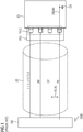
Ein Ladesystem 100 stellt die notwendige Energie sowie die Masseverbindung GND für das Ladekabel 20 zur Verfügung. Ein derartiges Ladesystem 100 mit den gezeigten Ladekabel 20 ist aus dem Stand der Technik bekannt und weist dabei Leistungsadern L+, L- bzw. im dreiphasigen Fall L1, L2, L3 auf. Einphasige Lösungen sowie kombinierte Lösungen sind ebenfalls möglich. Weiterhin weist das Ladekabel 20 eine PP-Signalleitung, den sogenannten "Proximity Pilot", eine CP-Signalleitung, den sogenannten "Control Pilot" sowie einen Schutzerdeleitung PE (auch "protective earth") auf. Zur Kommunikation zwischen dem Ladesystem 100 und dem Elektrofahrzeug 80, kann ein Rechtecksignal 50 sowie ein Kommunikationssignal 60 über die CP-Leitung bezüglich der Schutzerdeleitung PE zwischen dem Ladesystem 100 und dem Elektrofahrzeug 80 übertragen werden.A
Zusammenfassend betrifft die Erfindung ein störsicheres Ladekabel 20 für ein Elektrofahrzeug 80. Ferner betrifft die Erfindung einen Ladestecker P20, ein Ladesystem 100, sowie ein System 1000. Um ein Ladekabel bereitzustellen, das die Signalqualität zwischen Elektrofahrzeug und Ladeinfrastruktur, z.B. einer Ladesteuerung einer Ladesäule, erheblich verbessert, wird vorgeschlagen, dass das Ladekabel einen fahrzeugseitigen Stecker P20, eine Schutzerdeleitung PE und eine Signalmasseleitung SG aufweist, die fahrzeugseitig derart angeordnet sind, dass sich die Potentiale der Signalmasseleitung SG, der Schutzerdeleitung PE und einer fahrzeugseitigen Masseverbindung GND80 ausgleichen, wenn der Stecker P20 am Elektrofahrzeug 80 angeschlossen ist. Es ist weiter Aufgabe der Erfindung ein Ladesystem 100 sowie ein System 1000 bereitzustellen.In summary, the invention relates to an interference-
Claims (15)
einen fahrzeugseitigen Stecker (P20), eine Schutzerdeleitung (PE) und eine Signalmasseleitung (SG), die fahrzeugseitig derart angeordnet sind, dass sich die Potentiale der Signalmasseleitung (SG), der Schutzerdeleitung (PE) und der fahrzeugseitigen Masseverbindung (GND80) ausgleichen, wenn der Stecker (P20) am Elektrofahrzeug (80) angeschlossen ist.Charging cable (20) for an electric vehicle (80), the electric vehicle (80) having a vehicle-side ground connection (GND80), comprising:
a vehicle-side plug (P20), a protective earth line (PE) and a signal ground line (SG), which are arranged on the vehicle side in such a way that the potentials of the signal ground line (SG), the protective earth line (PE) and the vehicle-side ground connection (GND80) equalize, if the plug (P20) is connected to the electric vehicle (80).
Priority Applications (1)
| Application Number | Priority Date | Filing Date | Title |
|---|---|---|---|
| EP19162823.9A EP3708410A1 (en) | 2019-03-14 | 2019-03-14 | Fault-resistant charging cable for an electric vehicle |
Applications Claiming Priority (1)
| Application Number | Priority Date | Filing Date | Title |
|---|---|---|---|
| EP19162823.9A EP3708410A1 (en) | 2019-03-14 | 2019-03-14 | Fault-resistant charging cable for an electric vehicle |
Publications (1)
| Publication Number | Publication Date |
|---|---|
| EP3708410A1 true EP3708410A1 (en) | 2020-09-16 |
Family
ID=65812203
Family Applications (1)
| Application Number | Title | Priority Date | Filing Date |
|---|---|---|---|
| EP19162823.9A Withdrawn EP3708410A1 (en) | 2019-03-14 | 2019-03-14 | Fault-resistant charging cable for an electric vehicle |
Country Status (1)
| Country | Link |
|---|---|
| EP (1) | EP3708410A1 (en) |
Citations (1)
| Publication number | Priority date | Publication date | Assignee | Title |
|---|---|---|---|---|
| DE102017110956A1 (en) * | 2017-05-19 | 2018-11-22 | Dr. Ing. H.C. F. Porsche Aktiengesellschaft | Device for transmitting energy and information via a charging cable for an electric vehicle |
-
2019
- 2019-03-14 EP EP19162823.9A patent/EP3708410A1/en not_active Withdrawn
Patent Citations (1)
| Publication number | Priority date | Publication date | Assignee | Title |
|---|---|---|---|---|
| DE102017110956A1 (en) * | 2017-05-19 | 2018-11-22 | Dr. Ing. H.C. F. Porsche Aktiengesellschaft | Device for transmitting energy and information via a charging cable for an electric vehicle |
Similar Documents
| Publication | Publication Date | Title |
|---|---|---|
| EP3446369B1 (en) | Connector with interchangeable contact | |
| EP1830437B1 (en) | Electric contact | |
| DE102015206047A1 (en) | Adapter for a charging plug system | |
| WO2016156278A1 (en) | Motor vehicle comprising an electrical energy store and two charging interfaces, charging system and method | |
| EP3616977A1 (en) | Charging cable for an electric vehicle | |
| DE102017212435A1 (en) | An adapter device for a vehicle and method for loading a vehicle | |
| WO2015044452A1 (en) | Separation module for a charging plug socket | |
| DE102010045160A1 (en) | Control device for charging cable for battery of traction motor vehicle, has interfaces to connect respective charging cable and charging device with housing | |
| EP3451496B1 (en) | Communication with charging cable of a battery-powered vehicle | |
| DE202014000328U1 (en) | Charging system for charging an energy storage of an electric vehicle and charging cable therefor | |
| EP1988612A2 (en) | Mobile cooling device operated by low voltage direct current | |
| EP2601070A2 (en) | Method for charging at least one energy store of an electric vehicle | |
| EP2545678A1 (en) | Method for feeding at least one bus subscriber | |
| WO2012031779A1 (en) | Electro-optical plug-in connection, especially electro-optical usb connection | |
| EP3072057B1 (en) | Method for transmitting a usb signal and usb transmission system | |
| EP3708410A1 (en) | Fault-resistant charging cable for an electric vehicle | |
| EP3696010A1 (en) | Charging connector for charging an electricity storage device, system comprising a charging connector and method for processing electrical parameters for a charging connector | |
| DE102018215579A1 (en) | Charging device for an electrically drivable vehicle, vehicle electrical system and vehicle | |
| DE102018208357A1 (en) | Adapter for the electrical charging of a battery of a device and charging system therefor | |
| EP3546273A1 (en) | Transmission of electrical energy between a motor vehicle coupled to a charging station and the charging station | |
| DE102021110913A1 (en) | Charging connector device, charging cable and method for providing a charging connector device | |
| DE102016222271A1 (en) | Circuit arrangement for controlling a charging socket of an electric or hybrid vehicle and charging plug | |
| WO2012052184A1 (en) | Plug part of a plug-type apparatus | |
| DE102014221211A1 (en) | Method for charging a traction battery of an electric vehicle | |
| DE102019209654A1 (en) | Vehicle electrical system |
Legal Events
| Date | Code | Title | Description |
|---|---|---|---|
| PUAI | Public reference made under article 153(3) epc to a published international application that has entered the european phase |
Free format text: ORIGINAL CODE: 0009012 |
|
| STAA | Information on the status of an ep patent application or granted ep patent |
Free format text: STATUS: THE APPLICATION HAS BEEN PUBLISHED |
|
| AK | Designated contracting states |
Kind code of ref document: A1 Designated state(s): AL AT BE BG CH CY CZ DE DK EE ES FI FR GB GR HR HU IE IS IT LI LT LU LV MC MK MT NL NO PL PT RO RS SE SI SK SM TR |
|
| AX | Request for extension of the european patent |
Extension state: BA ME |
|
| STAA | Information on the status of an ep patent application or granted ep patent |
Free format text: STATUS: THE APPLICATION IS DEEMED TO BE WITHDRAWN |
|
| 18D | Application deemed to be withdrawn |
Effective date: 20210317 |