EP3675702B1 - Robot cleaner and control method thereof - Google Patents
Robot cleaner and control method thereof Download PDFInfo
- Publication number
- EP3675702B1 EP3675702B1 EP18876216.5A EP18876216A EP3675702B1 EP 3675702 B1 EP3675702 B1 EP 3675702B1 EP 18876216 A EP18876216 A EP 18876216A EP 3675702 B1 EP3675702 B1 EP 3675702B1
- Authority
- EP
- European Patent Office
- Prior art keywords
- robot cleaner
- sensor
- sensed
- traveling route
- directional moving
- Prior art date
- Legal status (The legal status is an assumption and is not a legal conclusion. Google has not performed a legal analysis and makes no representation as to the accuracy of the status listed.)
- Active
Links
- 238000000034 method Methods 0.000 title claims description 10
- 238000003032 molecular docking Methods 0.000 claims description 39
- 238000004140 cleaning Methods 0.000 description 28
- 239000000428 dust Substances 0.000 description 20
- 230000033001 locomotion Effects 0.000 description 18
- 238000004891 communication Methods 0.000 description 5
- 238000010586 diagram Methods 0.000 description 2
- 230000014509 gene expression Effects 0.000 description 2
- 239000004065 semiconductor Substances 0.000 description 2
- 238000007664 blowing Methods 0.000 description 1
- 238000013500 data storage Methods 0.000 description 1
- 230000001419 dependent effect Effects 0.000 description 1
- 238000001514 detection method Methods 0.000 description 1
- 235000012489 doughnuts Nutrition 0.000 description 1
- 230000000694 effects Effects 0.000 description 1
- 230000006870 function Effects 0.000 description 1
- 230000006698 induction Effects 0.000 description 1
- 238000012986 modification Methods 0.000 description 1
- 230000004048 modification Effects 0.000 description 1
- 230000003287 optical effect Effects 0.000 description 1
- 238000000638 solvent extraction Methods 0.000 description 1
- 239000000126 substance Substances 0.000 description 1
Images


Classifications
-
- A—HUMAN NECESSITIES
- A47—FURNITURE; DOMESTIC ARTICLES OR APPLIANCES; COFFEE MILLS; SPICE MILLS; SUCTION CLEANERS IN GENERAL
- A47L—DOMESTIC WASHING OR CLEANING; SUCTION CLEANERS IN GENERAL
- A47L9/00—Details or accessories of suction cleaners, e.g. mechanical means for controlling the suction or for effecting pulsating action; Storing devices specially adapted to suction cleaners or parts thereof; Carrying-vehicles specially adapted for suction cleaners
- A47L9/28—Installation of the electric equipment, e.g. adaptation or attachment to the suction cleaner; Controlling suction cleaners by electric means
- A47L9/2836—Installation of the electric equipment, e.g. adaptation or attachment to the suction cleaner; Controlling suction cleaners by electric means characterised by the parts which are controlled
- A47L9/2852—Elements for displacement of the vacuum cleaner or the accessories therefor, e.g. wheels, casters or nozzles
-
- G—PHYSICS
- G05—CONTROLLING; REGULATING
- G05D—SYSTEMS FOR CONTROLLING OR REGULATING NON-ELECTRIC VARIABLES
- G05D1/00—Control of position, course, altitude or attitude of land, water, air or space vehicles, e.g. using automatic pilots
- G05D1/02—Control of position or course in two dimensions
- G05D1/021—Control of position or course in two dimensions specially adapted to land vehicles
- G05D1/0212—Control of position or course in two dimensions specially adapted to land vehicles with means for defining a desired trajectory
- G05D1/0219—Control of position or course in two dimensions specially adapted to land vehicles with means for defining a desired trajectory ensuring the processing of the whole working surface
-
- A—HUMAN NECESSITIES
- A47—FURNITURE; DOMESTIC ARTICLES OR APPLIANCES; COFFEE MILLS; SPICE MILLS; SUCTION CLEANERS IN GENERAL
- A47L—DOMESTIC WASHING OR CLEANING; SUCTION CLEANERS IN GENERAL
- A47L11/00—Machines for cleaning floors, carpets, furniture, walls, or wall coverings
- A47L11/40—Parts or details of machines not provided for in groups A47L11/02 - A47L11/38, or not restricted to one of these groups, e.g. handles, arrangements of switches, skirts, buffers, levers
- A47L11/4011—Regulation of the cleaning machine by electric means; Control systems and remote control systems therefor
-
- A—HUMAN NECESSITIES
- A47—FURNITURE; DOMESTIC ARTICLES OR APPLIANCES; COFFEE MILLS; SPICE MILLS; SUCTION CLEANERS IN GENERAL
- A47L—DOMESTIC WASHING OR CLEANING; SUCTION CLEANERS IN GENERAL
- A47L11/00—Machines for cleaning floors, carpets, furniture, walls, or wall coverings
- A47L11/40—Parts or details of machines not provided for in groups A47L11/02 - A47L11/38, or not restricted to one of these groups, e.g. handles, arrangements of switches, skirts, buffers, levers
- A47L11/4061—Steering means; Means for avoiding obstacles; Details related to the place where the driver is accommodated
-
- A—HUMAN NECESSITIES
- A47—FURNITURE; DOMESTIC ARTICLES OR APPLIANCES; COFFEE MILLS; SPICE MILLS; SUCTION CLEANERS IN GENERAL
- A47L—DOMESTIC WASHING OR CLEANING; SUCTION CLEANERS IN GENERAL
- A47L11/00—Machines for cleaning floors, carpets, furniture, walls, or wall coverings
- A47L11/40—Parts or details of machines not provided for in groups A47L11/02 - A47L11/38, or not restricted to one of these groups, e.g. handles, arrangements of switches, skirts, buffers, levers
- A47L11/4063—Driving means; Transmission means therefor
- A47L11/4066—Propulsion of the whole machine
-
- A—HUMAN NECESSITIES
- A47—FURNITURE; DOMESTIC ARTICLES OR APPLIANCES; COFFEE MILLS; SPICE MILLS; SUCTION CLEANERS IN GENERAL
- A47L—DOMESTIC WASHING OR CLEANING; SUCTION CLEANERS IN GENERAL
- A47L9/00—Details or accessories of suction cleaners, e.g. mechanical means for controlling the suction or for effecting pulsating action; Storing devices specially adapted to suction cleaners or parts thereof; Carrying-vehicles specially adapted for suction cleaners
- A47L9/009—Carrying-vehicles; Arrangements of trollies or wheels; Means for avoiding mechanical obstacles
-
- A—HUMAN NECESSITIES
- A47—FURNITURE; DOMESTIC ARTICLES OR APPLIANCES; COFFEE MILLS; SPICE MILLS; SUCTION CLEANERS IN GENERAL
- A47L—DOMESTIC WASHING OR CLEANING; SUCTION CLEANERS IN GENERAL
- A47L9/00—Details or accessories of suction cleaners, e.g. mechanical means for controlling the suction or for effecting pulsating action; Storing devices specially adapted to suction cleaners or parts thereof; Carrying-vehicles specially adapted for suction cleaners
- A47L9/02—Nozzles
- A47L9/04—Nozzles with driven brushes or agitators
- A47L9/0461—Dust-loosening tools, e.g. agitators, brushes
- A47L9/0466—Rotating tools
- A47L9/0477—Rolls
-
- A—HUMAN NECESSITIES
- A47—FURNITURE; DOMESTIC ARTICLES OR APPLIANCES; COFFEE MILLS; SPICE MILLS; SUCTION CLEANERS IN GENERAL
- A47L—DOMESTIC WASHING OR CLEANING; SUCTION CLEANERS IN GENERAL
- A47L9/00—Details or accessories of suction cleaners, e.g. mechanical means for controlling the suction or for effecting pulsating action; Storing devices specially adapted to suction cleaners or parts thereof; Carrying-vehicles specially adapted for suction cleaners
- A47L9/02—Nozzles
- A47L9/04—Nozzles with driven brushes or agitators
- A47L9/0494—Height adjustment of dust-loosening tools
-
- A—HUMAN NECESSITIES
- A47—FURNITURE; DOMESTIC ARTICLES OR APPLIANCES; COFFEE MILLS; SPICE MILLS; SUCTION CLEANERS IN GENERAL
- A47L—DOMESTIC WASHING OR CLEANING; SUCTION CLEANERS IN GENERAL
- A47L9/00—Details or accessories of suction cleaners, e.g. mechanical means for controlling the suction or for effecting pulsating action; Storing devices specially adapted to suction cleaners or parts thereof; Carrying-vehicles specially adapted for suction cleaners
- A47L9/28—Installation of the electric equipment, e.g. adaptation or attachment to the suction cleaner; Controlling suction cleaners by electric means
- A47L9/2805—Parameters or conditions being sensed
- A47L9/2826—Parameters or conditions being sensed the condition of the floor
-
- A—HUMAN NECESSITIES
- A47—FURNITURE; DOMESTIC ARTICLES OR APPLIANCES; COFFEE MILLS; SPICE MILLS; SUCTION CLEANERS IN GENERAL
- A47L—DOMESTIC WASHING OR CLEANING; SUCTION CLEANERS IN GENERAL
- A47L9/00—Details or accessories of suction cleaners, e.g. mechanical means for controlling the suction or for effecting pulsating action; Storing devices specially adapted to suction cleaners or parts thereof; Carrying-vehicles specially adapted for suction cleaners
- A47L9/28—Installation of the electric equipment, e.g. adaptation or attachment to the suction cleaner; Controlling suction cleaners by electric means
- A47L9/2836—Installation of the electric equipment, e.g. adaptation or attachment to the suction cleaner; Controlling suction cleaners by electric means characterised by the parts which are controlled
- A47L9/2847—Surface treating elements
-
- B—PERFORMING OPERATIONS; TRANSPORTING
- B25—HAND TOOLS; PORTABLE POWER-DRIVEN TOOLS; MANIPULATORS
- B25J—MANIPULATORS; CHAMBERS PROVIDED WITH MANIPULATION DEVICES
- B25J11/00—Manipulators not otherwise provided for
- B25J11/008—Manipulators for service tasks
- B25J11/0085—Cleaning
-
- B—PERFORMING OPERATIONS; TRANSPORTING
- B25—HAND TOOLS; PORTABLE POWER-DRIVEN TOOLS; MANIPULATORS
- B25J—MANIPULATORS; CHAMBERS PROVIDED WITH MANIPULATION DEVICES
- B25J19/00—Accessories fitted to manipulators, e.g. for monitoring, for viewing; Safety devices combined with or specially adapted for use in connection with manipulators
- B25J19/02—Sensing devices
-
- B—PERFORMING OPERATIONS; TRANSPORTING
- B25—HAND TOOLS; PORTABLE POWER-DRIVEN TOOLS; MANIPULATORS
- B25J—MANIPULATORS; CHAMBERS PROVIDED WITH MANIPULATION DEVICES
- B25J5/00—Manipulators mounted on wheels or on carriages
- B25J5/007—Manipulators mounted on wheels or on carriages mounted on wheels
-
- B—PERFORMING OPERATIONS; TRANSPORTING
- B25—HAND TOOLS; PORTABLE POWER-DRIVEN TOOLS; MANIPULATORS
- B25J—MANIPULATORS; CHAMBERS PROVIDED WITH MANIPULATION DEVICES
- B25J9/00—Programme-controlled manipulators
- B25J9/16—Programme controls
- B25J9/1656—Programme controls characterised by programming, planning systems for manipulators
- B25J9/1664—Programme controls characterised by programming, planning systems for manipulators characterised by motion, path, trajectory planning
- B25J9/1666—Avoiding collision or forbidden zones
-
- B—PERFORMING OPERATIONS; TRANSPORTING
- B25—HAND TOOLS; PORTABLE POWER-DRIVEN TOOLS; MANIPULATORS
- B25J—MANIPULATORS; CHAMBERS PROVIDED WITH MANIPULATION DEVICES
- B25J9/00—Programme-controlled manipulators
- B25J9/16—Programme controls
- B25J9/1674—Programme controls characterised by safety, monitoring, diagnostic
- B25J9/1676—Avoiding collision or forbidden zones
-
- G—PHYSICS
- G05—CONTROLLING; REGULATING
- G05D—SYSTEMS FOR CONTROLLING OR REGULATING NON-ELECTRIC VARIABLES
- G05D1/00—Control of position, course, altitude or attitude of land, water, air or space vehicles, e.g. using automatic pilots
- G05D1/02—Control of position or course in two dimensions
- G05D1/021—Control of position or course in two dimensions specially adapted to land vehicles
- G05D1/0212—Control of position or course in two dimensions specially adapted to land vehicles with means for defining a desired trajectory
- G05D1/0214—Control of position or course in two dimensions specially adapted to land vehicles with means for defining a desired trajectory in accordance with safety or protection criteria, e.g. avoiding hazardous areas
-
- G—PHYSICS
- G05—CONTROLLING; REGULATING
- G05D—SYSTEMS FOR CONTROLLING OR REGULATING NON-ELECTRIC VARIABLES
- G05D1/00—Control of position, course, altitude or attitude of land, water, air or space vehicles, e.g. using automatic pilots
- G05D1/02—Control of position or course in two dimensions
- G05D1/021—Control of position or course in two dimensions specially adapted to land vehicles
- G05D1/0212—Control of position or course in two dimensions specially adapted to land vehicles with means for defining a desired trajectory
- G05D1/0225—Control of position or course in two dimensions specially adapted to land vehicles with means for defining a desired trajectory involving docking at a fixed facility, e.g. base station or loading bay
-
- G—PHYSICS
- G05—CONTROLLING; REGULATING
- G05D—SYSTEMS FOR CONTROLLING OR REGULATING NON-ELECTRIC VARIABLES
- G05D1/00—Control of position, course, altitude or attitude of land, water, air or space vehicles, e.g. using automatic pilots
- G05D1/02—Control of position or course in two dimensions
- G05D1/021—Control of position or course in two dimensions specially adapted to land vehicles
- G05D1/0231—Control of position or course in two dimensions specially adapted to land vehicles using optical position detecting means
- G05D1/0238—Control of position or course in two dimensions specially adapted to land vehicles using optical position detecting means using obstacle or wall sensors
-
- A—HUMAN NECESSITIES
- A47—FURNITURE; DOMESTIC ARTICLES OR APPLIANCES; COFFEE MILLS; SPICE MILLS; SUCTION CLEANERS IN GENERAL
- A47L—DOMESTIC WASHING OR CLEANING; SUCTION CLEANERS IN GENERAL
- A47L2201/00—Robotic cleaning machines, i.e. with automatic control of the travelling movement or the cleaning operation
- A47L2201/02—Docking stations; Docking operations
- A47L2201/022—Recharging of batteries
-
- A—HUMAN NECESSITIES
- A47—FURNITURE; DOMESTIC ARTICLES OR APPLIANCES; COFFEE MILLS; SPICE MILLS; SUCTION CLEANERS IN GENERAL
- A47L—DOMESTIC WASHING OR CLEANING; SUCTION CLEANERS IN GENERAL
- A47L2201/00—Robotic cleaning machines, i.e. with automatic control of the travelling movement or the cleaning operation
- A47L2201/04—Automatic control of the travelling movement; Automatic obstacle detection
-
- A—HUMAN NECESSITIES
- A47—FURNITURE; DOMESTIC ARTICLES OR APPLIANCES; COFFEE MILLS; SPICE MILLS; SUCTION CLEANERS IN GENERAL
- A47L—DOMESTIC WASHING OR CLEANING; SUCTION CLEANERS IN GENERAL
- A47L2201/00—Robotic cleaning machines, i.e. with automatic control of the travelling movement or the cleaning operation
- A47L2201/06—Control of the cleaning action for autonomous devices; Automatic detection of the surface condition before, during or after cleaning
-
- A—HUMAN NECESSITIES
- A47—FURNITURE; DOMESTIC ARTICLES OR APPLIANCES; COFFEE MILLS; SPICE MILLS; SUCTION CLEANERS IN GENERAL
- A47L—DOMESTIC WASHING OR CLEANING; SUCTION CLEANERS IN GENERAL
- A47L9/00—Details or accessories of suction cleaners, e.g. mechanical means for controlling the suction or for effecting pulsating action; Storing devices specially adapted to suction cleaners or parts thereof; Carrying-vehicles specially adapted for suction cleaners
- A47L9/28—Installation of the electric equipment, e.g. adaptation or attachment to the suction cleaner; Controlling suction cleaners by electric means
- A47L9/2868—Arrangements for power supply of vacuum cleaners or the accessories thereof
- A47L9/2873—Docking units or charging stations
-
- B—PERFORMING OPERATIONS; TRANSPORTING
- B60—VEHICLES IN GENERAL
- B60B—VEHICLE WHEELS; CASTORS; AXLES FOR WHEELS OR CASTORS; INCREASING WHEEL ADHESION
- B60B19/00—Wheels not otherwise provided for or having characteristics specified in one of the subgroups of this group
- B60B19/003—Multidirectional wheels
-
- Y—GENERAL TAGGING OF NEW TECHNOLOGICAL DEVELOPMENTS; GENERAL TAGGING OF CROSS-SECTIONAL TECHNOLOGIES SPANNING OVER SEVERAL SECTIONS OF THE IPC; TECHNICAL SUBJECTS COVERED BY FORMER USPC CROSS-REFERENCE ART COLLECTIONS [XRACs] AND DIGESTS
- Y02—TECHNOLOGIES OR APPLICATIONS FOR MITIGATION OR ADAPTATION AGAINST CLIMATE CHANGE
- Y02B—CLIMATE CHANGE MITIGATION TECHNOLOGIES RELATED TO BUILDINGS, e.g. HOUSING, HOUSE APPLIANCES OR RELATED END-USER APPLICATIONS
- Y02B40/00—Technologies aiming at improving the efficiency of home appliances, e.g. induction cooking or efficient technologies for refrigerators, freezers or dish washers
Definitions
- the disclosure relates to a robot cleaner and a control method thereof, and more particularly, to a robot cleaner having wheels capable of moving in all directions to have enhanced traveling ability in various directions.
- a robot cleaner is a device for automatically cleaning a cleaning space by suctioning foreign substances such as dust accumulated on a floor while traveling in the cleaning space without being operated by a user. That is, the robot cleaner cleans a cleaning space while traveling in the cleaning space.
- the robot cleaner generally performs the cleaning automatically according to its own planned route regardless of the intention of the user.
- the robot cleaner generates a route for avoiding obstacles when it detects the obstacles while it travels in a cleaning space and travels in the cleaning space while avoiding the obstacles.
- the robot cleaner repeats an operation for avoiding the obstacles according to a predetermined traveling pattern, thereby delaying the cleaning time or increasing the battery consumption of the robot cleaner.
- US2007/272463 discloses an omnidirectional robot cleaner, composed of a platform and a plurality of driving units for driving and controlling the movement of the platform, in which the platform further comprises a sensing unit, for obstacle detection.
- EP1441271 discloses a cleaning robot including a rotational cylinder combined with a rotational axis of the main motor so as to be rotated at a certain angle; and plural position information sensors installed at the rotational cylinder at a certain angle in order to sense surroundings.
- the robot cleaner may further include a sensor rotation module rotatably coupled to the body unit, wherein the sensor may be provided in the sensor rotation module.
- the sensor may rotate in a direction of avoiding the sensed obstacles, and the controller may determine a traveling route of the robot cleaner to avoid the obstacles based on the rotational direction of the sensor.
- the controller may determine a traveling route for avoiding the obstacles in a state where the body unit of the robot cleaner is not rotated based on position information of the sensed obstacles.
- the target object may include a wall which the robot cleaner follows to perform the cleaning, and a docking station for charging a battery of the robot cleaner.
- the controller controls, when the traveling route is determined, the multi-directional moving wheel so that the robot cleaner moves to the determined traveling route to reach the sensed target object in a state where the body unit is not rotated.
- the controller may control the multi-directional moving wheel to rotate the body unit so that the one surface of the brush unit is positioned in a direction parallel to the one surface of the sensed target object based on the angle of the one surface of the sensed target object.
- the controller may control, when the body unit is rotated and the one surface of the brush unit is positioned in the direction parallel to the one surface of the sensed target object, the multi-directional moving wheel to move the robot cleaner along the determined traveling route, and the body unit may not be rotated while the robot cleaner moves along the determined traveling route.
- the multi-directional moving wheel provided at the lower portion of the body unit may be capable of forward movement, rearward movement, leftward/rightward movement, diagonal movement, and rotation in place, thereby moving the body unit in multiple directions.
- a plurality of the multi-directional moving wheels may be provided at the lower portion of the body unit, and the respective operations of the multi-directional moving wheels may be individually controlled by the controller.
- the control method may further include controlling the sensor of the robot cleaner to rotate in a direction of avoiding the sensed obstacle, wherein a traveling route of the robot cleaner may be determined to avoid the obstacle based on the rotational direction of the sensor.
- the determining of the traveling route of the robot cleaner may include determining the traveling route to avoid the obstacle in a state where the body unit of the robot cleaner is not rotated, based on location information of the sensed obstacle.
- the target object may include a wall which the robot cleaner follows to perform the cleaning, and a docking station for charging a battery of the robot cleaner.
- the control method may further include controlling the sensor to rotate in a direction in which the robot cleaner travels to reach the sensed target object, wherein a traveling route of the robot cleaner may be determined so that the robot cleaner reaches the sensed target object based on the rotational direction of the sensor.
- the controlling of the multi-directional moving wheel of the robot cleaner may include controlling, when the traveling route is determined, the multi-directional moving wheel so that the robot cleaner moves to the determined traveling route to reach the sensed target object in a state where the body unit is not rotated.
- the controlling of the multi-directional moving wheel of the robot cleaner may include controlling the multi-directional moving wheel to rotate the body unit so that the one surface of the brush unit is positioned in a direction parallel to the one surface of the sensed target object based on the angle of the one surface of the sensed target object.
- the controlling of the multi-directional moving wheel of the robot cleaner may further include controlling, when the body unit is rotated and the one surface of the brush unit is positioned in the direction parallel to the one surface of the sensed target object, the multi-directional moving wheel to move the robot cleaner along the determined traveling route, wherein the body unit may not be rotated while the robot cleaner moves along the determined traveling route.
- the robot cleaner according to an embodiment of the present disclosure can ensure effective driving performance by sensing obstacles located in the vicinity of the robot cleaner through a rotatable sensor. Further, the robot cleaner according to an embodiment of the present disclosure can improve the obstacle avoidance ability and improve the freedom of movement even in a narrow area by traveling in various directions without rotating the body of the robot cleaner through wheels capable of moving in all directions.
- first, second, etc. may be used herein to describe various components, these components should not be limited by these terms, and the terms are only used to distinguish one component from another.
- first component may be referred to as a second component, and similarly, the second component may also be referred to as a first component.
- second component may also be referred to as a first component.
- the term "and/or" includes any combination of a plurality of related items or any of a plurality of related items.
- front and forward refer to a front and a forward direction based on the robot cleaner shown in FIG. 1
- rearward refers to a rearward direction of the robot cleaner
- FIG. 1 is a perspective view of a robot cleaner according to an embodiment of the present disclosure
- FIG. 2 is a bottom view illustrating a bottom surface of a robot cleaner according to an embodiment of the present disclosure
- FIG. 3 is a view illustrating traveling forms of a robot cleaner according to an embodiment of the present disclosure
- FIG. 4 is a control block diagram of a robot cleaner according to an embodiment of the present disclosure.
- FIGS. 1 and 2 a robot cleaner 1 according to an embodiment of the present disclosure will be described.
- the robot cleaner 1 includes a body unit 110 and a brush unit 130.
- the body unit 110 may include a driving device 112, a main body for accommodating a dust collecting device therein, and a cover 121 for covering an upper surface of the main body.
- the body unit 110 may be coupled with the brush unit 130 to rotate or move in the same direction.
- the main body may have a space therein for accommodating the dust collecting device.
- the main body may include a dust collecting passage for guiding air containing foreign matter such as dust sucked from the brush unit 130 to the dust collecting device.
- the main body may also include a flow passage partitioning portion for forming the dust collecting passage.
- the driving device 112 may include multi-directional moving wheels 113 to move the main body in a cleaning area.
- the driving device 112 may include a driving source (not shown) for rotationally driving the multi-directional moving wheels 113.
- the multi-directional moving wheels 113 may be arranged to protrude downward from a bottom surface of the main body.
- the multi-directional moving wheels 113 may be provided on the left and right sides of the bottom surface of the main body, respectively.
- a plurality of the multi-directional moving wheels 113 may be provided on the bottom surface of the main body.
- the robot cleaner 1 according to an embodiment of the present disclosure has four multi-directional moving wheels 113a, 113b, 113c, and 113d for the sake of illustration, there is no restriction on the number and location of the multi-directional moving wheels 113, and various embodiments may be presented.
- the driving device 112 may include electric motors connected to the plurality of multi-directional moving wheels 113 to generate a rotational driving force, and power transmitting members for transmitting the rotational driving force of the electric motors to the multi-directional moving wheels 113.
- the driving device 112 may be connected to the plurality of multi-directional moving wheels 113 to drive the multi-directional moving wheels 113 individually, and the driving of the driving device 112 is controlled by a controller 100.
- the controller 100 may individually control the operation states such as the operation, stop, rotation direction, and the like of the driving device 112, and the multi-directional moving wheels 113 may be diverted in various directions according to the operation, stop, and rotation direction of the driving device 112, so that the robot cleaner 1 may effectively avoid obstacles and increase the degree of freedom of movement.
- the multi-directional moving wheels 113 are provided at a lower portion of the body unit 110, and may be capable of forward movement, rearward movement, leftward/rightward movement, diagonal movement, and rotation in place, thereby moving the body unit 110 in multiple directions.
- the dust collecting device may be accommodated inside the main body.
- the dust collecting device may include a suction motor providing power for sucking dust, and a dust collecting container for storing the sucked dust.
- the air containing foreign matter sucked in from the brush unit 130 may be introduced into the dust collecting device through a suction passage.
- the cover 121 may cover the upper surface of the main body. Specifically, the cover 121 may cover the upper surface of the main body coupled with the brush unit 130. That is, the cover 121 may be coupled to an upper portion of the brush unit 130 to cover the upper surface of the main body.
- the cover 121 includes a sensor 123 for sensing obstacles.
- the sensor 123 may be arranged to sense in a forward direction along the traveling direction of the driving device 112.
- the sensor 123 is provided to be rotatable with respect to the body unit 110 of the robot cleaner 1 and senses obstacles located on or around a traveling route of the robot cleaner 1 from the front or side of the robot cleaner 1.
- the position where the sensor 123 is provided is merely an example, and there is no limitation on the position where the sensor 123 is provided or the number of the sensors 123.
- the cover 121 may include a sensor rotation module 124 that is rotatably coupled with respect to the body unit 110.
- the sensor rotation module 124 may be provided in a circular shape at an upper portion of the body unit 110 and may rotate clockwise or counterclockwise under the control of the controller 100.
- the sensor 123 may be provided in the sensor rotation module 124, and may rotate clockwise or counterclockwise with respect to the body unit 110 in accordance with the rotation of the sensor rotation module 124.
- the sensor 123 senses obstacles on the traveling route of the robot cleaner 1. When an obstacle is sensed, the sensor 123 rotates in a direction of avoiding the obstacle and searches the traveling route of the robot cleaner 1. In addition, the sensor 123 senses a target object for the robot cleaner 1 to travel toward, and may rotate in a direction of heading toward the sensed target object and may search the traveling route of the robot cleaner 1.
- the sensor 123 may first rotate in the direction to travel before the robot cleaner 1 determines the traveling route and starts traveling, thereby searching the traveling route of the robot cleaner 1 for obstacles.
- the sensors 123 may be used, such as a motion sensor, an image sensor, an infrared sensor, a radio wave sensor, and a three-dimensional sensing sensor.
- the sensor 123 may sense a predetermined distance to an obstacle located on the traveling route of the robot cleaner 1 and recognize the existence of the obstacle.
- the motion sensor may recognizes the motion of a moving obstacle and obtain a three-dimensional shape of the obstacle, and the image sensor may also obtain a shape of an obstacle.
- the infrared sensor or the radio wave sensor may measure the distance to an obstacle by transmitting an infrared ray or a radio wave to an object, and when a plurality of the sensors 123 are provided, not only one-dimensional distance, but also shapes and positions of two-dimensional and three-dimensional obstacles may be sensed.
- the three-dimensional sensing sensor may also recognize the distance to an obstacle and a three-dimensional shape of the obstacle. Because two-dimensional and three-dimensional shapes may be sensed when the plurality of sensors 123 capable of recognizing the distance and shape on a one-dimensional plane are provided, two- or three-dimensional obstacles may also be sensed depending on the type and number of the sensors 123.
- the robot cleaner 1 may move in the traveling route by sensing the traveling route through the sensor 123 and avoiding obstacles.
- the cover 121 may include a dust checker 125 provided to check the dust collected inside the dust collecting device.
- the dust checker 125 may be formed to be transparent so that the inside of the dust collecting device may be seen without opening the cover 121.
- the brush unit 130 may include a brush part 131 for sucking dust from the bottom surface and a base part 136 coupled to a lower portion of the body unit 110.
- the brush part 131 may include a roller 132 rotatably mounted in the brush part 131 and a brush 133 provided on an outer circumferential surface of the roller 132. As the roller 132 rotates, the brush 133 may sweep foreign matter from the bottom surface into a suction passage 131a.
- the base part 136 may form a lower portion of the outer surface of the robot cleaner 1.
- the base part 136 may be formed in a substantially circular shape having a space into which the main body may be inserted. That is, the base part 136 may have a donut shape.
- the base part 136 may include a second passage forming portion forming a connection passage together with a first passage forming portion.
- the second passage forming portion may extend along an inner circumferential surface of the base part 136.
- connection passage is formed between the inner circumferential surface of the brush unit 130 and the outer circumferential surface of the body unit 110 to connect the suction passage and the dust collecting passage, and may extend along a circumferential direction of the body unit 110.
- the multi-directional moving wheels 113 may include the front right multi-directional moving wheel 113a, the front left multi-directional moving wheel 113b, the rear right multi-directional moving wheel 113c and the rear left multi-directional moving wheel 113d.
- the driving device 112 drives all of the four multi-directional moving wheels 113 in the forward direction in accordance with the control of the controller 100.
- the direction of the force of the front right multi-directional moving wheel 113a and the direction of the force of the front left multi-directional moving wheel 113b face inward at 45°
- the direction of the force of the rear right multi-directional moving wheel 113c and the direction of the force of the rear left multi-directional moving wheel 113d face outward at 45°, so that the traveling of the robot cleaner 1 in the forward straight direction may be performed by the combination of the directions of the forces as above.
- the sensor 123 included in the sensor rotation module 124 may rotate in the forward direction with respect to the body unit 110 to search a traveling route in which the robot cleaner 1 moves straight in the forward direction and to sense obstacles located in the vicinity of the robot cleaner 1 while the robot cleaner 1 is moving in the forward direction.
- the driving device 112 drives all of the four multi-directional moving wheels 113 in the rearward direction in accordance with the control of the controller 100.
- the direction of the force of the front right multi-directional moving wheel 113a and the direction of the force of the front left multi-directional moving wheel 113b face outward at 45°
- the direction of the force of the rear right multi-directional moving wheel 113c and the direction of the force of the rear left multi-directional moving wheel 113d face inward at 45°, so that the traveling of the robot cleaner 1 in the rearward straight direction may be performed by the combination of the directions of the forces as above.
- the sensor 123 included in the sensor rotation module 124 may rotate in the rearward direction with respect to the body unit 110 to search a traveling route in which the robot cleaner 1 moves straight in the rearward direction and to sense obstacles located in the vicinity of the robot cleaner 1 while the robot cleaner 1 is moving in the rearward direction.
- the driving device 112 drives the front left multi-directional moving wheel 113b and the rear right multi-directional moving wheel 113c provided diagonally thereto in the forward direction and drives the front right multi-directional moving wheel 113a and the rear left multi-directional moving wheel 113d provided diagonally thereto in the rearward direction, in accordance with the control of the controller 100.
- the direction of the force of the front right multi-directional moving wheel 113a and the direction of the force of the rear right multi-directional moving wheel 113c face inward at 45°
- the direction of the force of the front left multi-directional moving wheel 113b and the direction of the force of the rear left multi-directional moving wheel 113d face outward at 45°, so that the traveling of the robot cleaner 1 in the rightward straight direction may be performed by the combination of the directions of the forces as above.
- the sensor 123 included in the sensor rotation module 124 may rotate in the rightward direction with respect to the body unit 110 to search a traveling route in which the robot cleaner 1 moves straight in the rightward direction and to sense obstacles located in the vicinity of the robot cleaner 1 while the robot cleaner 1 is moving in the rightward direction.
- the driving device 112 drives the front left multi-directional moving wheel 113b and the rear right multi-directional moving wheel 113c provided diagonally thereto in the rearward direction and drives the front right multi-directional moving wheel 113a and the rear left multi-directional moving wheel 113d provided diagonally thereto in the forward direction, in accordance with the control of the controller 100.
- the direction of the force of the front right multi-directional moving wheel 113a and the direction of the force of the rear right multi-directional moving wheel 113c face outward at 45°
- the direction of the force of the front left multi-directional moving wheel 113b and the direction of the force of the rear left multi-directional moving wheel 113d face inward at 45°, so that the traveling of the robot cleaner 1 in the leftward straight direction may be performed by the combination of the directions of the forces as above.
- the sensor 123 included in the sensor rotation module 124 may rotate in the leftward direction with respect to the body unit 110 to search for a traveling route in which the robot cleaner 1 moves straight in the leftward direction and to sense obstacles located in the vicinity of the robot cleaner 1 while the robot cleaner 1 is moving in the leftward direction.
- the driving device 112 does not drive the front left multi-directional moving wheel 113b and the rear right multi-directional moving wheel 113c provided diagonally thereto and drives the front right multi-directional moving wheel 113a and the rear left multi-directional moving wheel 113d provided diagonally thereto in the forward direction, in accordance with the control of the controller 100.
- the robot cleaner 1 may travel straight in the forward left diagonal direction.
- the sensor 123 included in the sensor rotation module 124 may rotate in the forward left diagonal direction with respect to the body unit 110 to search a traveling route in which the robot cleaner 1 moves straight in the forward left diagonal direction and to sense obstacles located in the vicinity of the robot cleaner 1 while the robot cleaner 1 is moving in the forward left diagonal direction.
- the driving device 112 does not drive the front right multi-directional moving wheel 113a and the rear left multi-directional moving wheel 113d provided diagonally thereto and drives the front left multi-directional moving wheel 113b and the rear right multi-directional moving wheel 113c provided diagonally thereto in the forward direction, in accordance with the control of the controller 100.
- the robot cleaner 1 may travel straight in the forward right diagonal direction.
- the sensor 123 included in the sensor rotation module 124 may rotate in the forward right diagonal direction with respect to the body unit 110 to search a traveling route in which the robot cleaner 1 moves straight in the forward right diagonal direction and to sense obstacles located in the vicinity of the robot cleaner 1 while the robot cleaner 1 is moving in the forward right diagonal direction.
- the driving device 112 may not drive the front right multi-directional moving wheel 113a and the rear left multi-directional moving wheel 113d provided diagonally thereto and may drive the front left multi-directional moving wheel 113b and the rear right multi-directional moving wheel 113c provided diagonally thereto in the rearward direction, in accordance with the control of the controller 100. According to the above driving, the robot cleaner 1 may travel straight in the rearward left diagonal direction.
- the sensor 123 included in the sensor rotation module 124 may rotate straight in the rearward left diagonal direction with respect to the body unit 110 to search a traveling route in which the robot cleaner 1 moves straight in the rearward left diagonal direction and to sense obstacles located in the vicinity of the robot cleaner 1 while the robot cleaner 1 is moving in the rearward left diagonal direction.
- the driving device 112 may not drive the front left multi-directional moving wheel 113b and the rear right multi-directional moving wheel 113c provided diagonally thereto and may drive the front right multi-directional moving wheel 113a and the rear left multi-directional moving wheel 113d provided diagonally thereto in the rearward direction, in accordance with the control of the controller 100. According to the above driving, the robot cleaner 1 may travel straight in the rearward right diagonal direction diagonal direction.
- the sensor 123 included in the sensor rotation module 124 may rotate straight in the rearward right diagonal direction with respect to the body unit 110 to search a traveling route in which the robot cleaner 1 moves straight in the rearward right diagonal direction and to sense obstacles located in the vicinity of the robot cleaner 1 while the robot cleaner 1 is moving in the rearward right diagonal direction.
- the robot cleaner 1 may include a storage 90 for storing data related to the control of the robot cleaner 1, the controller 100 for controlling each configuration of the robot cleaner 1, and a communicator 140 for transmitting and receiving data through communication between the robot cleaner 1 and an external device such as a user terminal 200.
- the storage 90 may store control programs and control data for controlling the robot cleaner 1, and map information of the cleaning space acquired while the robot cleaner 1 is traveling.
- the storage 90 may store data for movement limiting directions of the robot cleaner 1 sensed by the sensor 123 on the traveling route of the robot cleaner 1 or data for routes that the robot cleaner 1 moves while avoiding obstacles.
- the storage 90 may also store data on a traveling route determined in a direction in which the robot cleaner 1 travels to reach a target object sensed by the sensor 123.
- the storage 90 may store data on the angle at which the sensor rotation module 124 rotates so that the robot cleaner 1 may travel while avoiding obstacles on the traveling route.
- the storage 90 may operate as an auxiliary storage device for backing up a memory included in the controller 100, which will be described later, and may be configured as a nonvolatile storage medium in which the stored data is not erased if the robot cleaner 1 is powered off.
- the storage 90 may include a semiconductor device drive that stores data in a semiconductor device, a magnetic disk drive that stores data on a magnetic disk, and the like.
- the communicator 140 when the traveling route of the robot cleaner 1 may not be secured due to an obstacle located around the robot cleaner 1, may transmit the situation to an external device such as the user terminal 200. That is, the communicator 140 may transmit to the user terminal 200 the situation in which the traveling route of the robot cleaner 1 cannot be secured, so that the user may recognize the situation through a sound or a screen.
- the user terminal 200 receiving data from the robot cleaner 1 through the communicator 140 may include various wired and wireless communication devices such as a smart phone and a PDA.
- the communicator 140 may include a Wi-Fi communication module, a USB communication module, and a Bluetooth communication module.
- the controller 100 collectively controls the operation of the robot cleaner 1.
- a control algorithm of the controller 100 for collectively controlling the operation of the robot cleaner 1 according to an embodiment of the present disclosure will be described below with reference to FIGS. 5 to 14 .
- FIG. 5 is a view illustrating a sensor according to an embodiment of the present disclosure rotating according to a traveling route of a robot cleaner
- FIGS. 6 to 8 illustrate examples in which a robot cleaner according to an embodiment of the present disclosure travels while avoiding obstacles without rotating a body unit.
- FIG. 9 illustrates a robot cleaner according to an embodiment of the present disclosure traveling in a direction of reaching a wall surface while sensing the wall surface
- FIG. 10 illustrates a robot cleaner according to an embodiment of the present disclosure traveling in a direction of reaching a docking station while sensing the docking station.
- FIGS. 11 to 13 are flowcharts illustrating a traveling algorithm of a robot cleaner according to an embodiment of the present disclosure
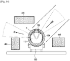
- FIG. 14 is a conceptual view illustrating a robot cleaner according to an embodiment of the present disclosure sensing obstacles around the robot cleaner while being coupled to a docking station.
- the traveling route may be changed while the robot cleaner 1 is traveling, and the sensor 123 may be rotated toward the traveling route that is to be changed. That is, when the robot cleaner 1 travels from position (1) and reaches position (2), the sensor 123 may search for the traveling route of the robot cleaner 1, and the sensor rotation module 124 may be rotated toward the traveling route under the control of the controller 100.
- the body unit 110 of the robot cleaner 1 is in a fixed state without rotating, and the sensor 123 may rotate in the forward right diagonal direction based on the rotation of the sensor rotation module 124.
- the sensor 123 may be rotated clockwise according to the rotation of the sensor rotation module 124, and may also be rotated by an angle at which the traveling route of the robot cleaner 1 is changed.
- the controller 100 may determine the traveling route of the robot cleaner 1 based on the rotational direction of the sensor 123. That is, the sensor 123 senses the traveling route of the robot cleaner 1 and may rotate clockwise, and when the sensor 123 rotates to a particular angle with respect to the existing traveling direction and then stops, the controller 100 may determine the traveling route of the robot cleaner 1 based on the rotation direction and the rotation angle of the sensor 123.
- the controller 100 may control the multi-directional moving wheels 113 so that the robot cleaner 1 moves to the determined traveling route in a state where the body unit 110 is not rotated.
- the controller 100 controls the driving device 112 so that the front right multi-directional moving wheel 113a and the rear left multi-directional moving wheel 113d provided diagonally thereto are not driven and the front left multi-directional moving wheel 113b and the rear right multi-directional moving wheel 113c provided diagonally thereto is driven in the forward direction.
- the robot cleaner 1 may travel in the front rightward diagonal direction.
- the sensor 123 may sense an obstacle ob1 (operation 310) and transmit data on the sensed obstacle ob1 to the controller 100.
- the robot cleaner 1 When the robot cleaner 1 reaches position (2), the robot cleaner 1 comes face to face with the obstacle ob1 and is no longer able to travel, and thus must travel to avoid the obstacle ob1.
- the sensor 123 may rotates in a direction of avoiding the sensed obstacle ob1 (operation 320) so that the robot cleaner 1 may travel to avoid the obstacle ob1. That is, when the robot cleaner 1 reaches position (2), the sensor 123 may sense a traveling route that causes the robot cleaner 1 to avoid the obstacle ob1, and may be rotated in the traveling route direction of avoiding the obstacle ob1 according to the rotation of the sensor rotation module 124.
- the body unit 110 of the robot cleaner 1 is in a fixed state without rotating, and the sensor 123 may rotate in the forward right diagonal direction based on the rotation of the sensor rotation module 124.
- the sensor 123 may be rotated clockwise according to the rotation of the sensor rotation module 124, and may also be rotated by an angle at which the traveling route of the robot cleaner 1 is changed.
- the controller 100 may determine a traveling route in which the robot cleaner 1 may avoid the obstacle ob1 based on the rotational direction of the sensor 123 (operation 330). That is, the sensor 123 may be rotated in the clockwise direction by sensing a traveling route so that the robot cleaner 1 avoids the obstacle ob1, and when the sensor 123 stops after rotating by a particular angle with respect to the existing traveling direction, the controller 100 may determine a traveling route that causes the robot cleaner 1 to avoid the obstacle ob1 based on the rotational direction and the rotational angle of the sensor 123.
- the sensor 123 may sense whether there are other obstacles located on the determined traveling route (operation 340).
- the controller 100 may control the multi-directional moving wheels 113 to move the robot cleaner 1 to the determined traveling route without rotating the body unit 110 (operation 350).
- the controller 100 controls the driving device 112 so that the front right multi-directional moving wheel 113a and the rear left multi-directional moving wheel 113d provided diagonally thereto are not driven and the front left multi-directional moving wheel 113b and the rear right multi-directional moving wheel 113c provided diagonally thereto is driven in the forward direction.
- the robot cleaner 1 may travel in the forward right diagonal direction to avoid the obstacle ob1.
- the direction in which the body unit 110 is heading at position (2) before the traveling route of the robot cleaner 1 is changed and the direction in which the body unit 110 is heading at position (3) to position (4) after the traveling route of the robot cleaner 1 is changed are the same, and the positions of the sensor 123 at position (2) and position (3) are different.
- the sensor 123 may sense an obstacle located on the traveling route of the robot cleaner 1 in real time (operation 370), and if there are no obstacles as a result of the sensing, the robot cleaner 1 may continue traveling (operation 380). In addition, the controller 100 may determine whether cleaning of the cleaning space of the robot cleaner 1 has ended (operation 390).
- the sensor 123 may sense an obstacle ob2 (operation 310) and may transmit the data of the sensed obstacle ob2 to the controller 100.
- the sensor 123 may be rotated (operation 320) in a direction of avoiding the sensed obstacle ob2 so that the robot cleaner 1 may travel while avoiding the obstacle ob2. That is, when the robot cleaner 1 reaches position (2), the sensor 123 may sense a traveling route that causes the robot cleaner 1 to avoid the obstacle ob2, and may be rotated in the traveling route direction avoiding the obstacle ob2 in accordance with the rotation of the sensor rotation module 124.
- the body unit 110 of the robot cleaner 1 is in a fixed state without rotating, and the sensor 123 may be rotated by 90° in the clockwise direction based on the rotation of the sensor rotation module 124.
- the controller 100 may control the multi-directional moving wheels 113 (operation 350) to move the robot cleaner 1 to the determined traveling route in a state where the body unit 110 is not rotated.
- the controller 100 controls the driving device 112 to drive the front left multi-directional moving wheel 113b and the rear right multi-directional moving wheel 113c provided diagonally thereto in the diagonal forward direction and drive the front right multi-directional moving wheel 113a and the rear left multi-directional moving wheel 113d provided diagonally thereto in the diagonal rearward direction.
- the robot cleaner 1 may travel in the rightward direction while avoiding the obstacle ob2.
- the direction in which the body unit 110 is heading at position (2) before the traveling route of the robot cleaner 1 is changed and the direction in which the body unit 110 is heading at position (3) where the robot cleaner 1 travels in the rightward direction after changing the traveling route and reaches are the same, and the positions of the sensor 123 at position (2) and position (3) are different.
- the controller 100 may determine various traveling routes to travel while avoiding the obstacle ob2.
- the sensor 123 may be rotated in the front right diagonal direction based on the rotation of the sensor rotation module 124 in a state where the body unit 110 of the robot cleaner 1 is not rotated. At this time, the sensor 123 may be rotated counterclockwise according to the rotation of the sensor rotation module 124, and may also be rotated by an angle at which the traveling route of the robot cleaner 1 is changed.
- the controller 100 may determine a traveling route P1 that allows the robot cleaner 1 to avoid the obstacle ob2 based on the rotational direction of the sensor 123.
- the controller 100 may control the multi-directional moving wheels 113 so that the robot cleaner 1 moves to the determined traveling route P1 in a state where the body unit 110 is not rotated.
- the controller 100 controls the driving device 112 not to drive the front right multi-directional moving wheel 113a and the rear left multi-directional moving wheel 113d provided diagonally thereto, and to drive the front left multi-directional moving wheel 113b and the rear right multi-directional moving wheel 113c provided diagonally thereto in the forward direction. According to the above driving, the robot cleaner 1 may travel in the front rightward diagonal direction while avoiding the obstacle ob2.
- the direction in which the body unit 110 is heading at position (3) before the traveling route of the robot cleaner 1 is changed and the direction in which the body unit 110 is heading at position (4) after the traveling route of the robot cleaner 1 is changed are the same, and the positions of the sensor 123 at position (3) and position (4) are different.
- the robot cleaner 1 may travel along a traveling route P2 in order to avoid the obstacle ob2 at position (3).
- the sensor 123 may be rotated counterclockwise according to the rotation of the sensor rotation module 124, and may also be rotated by an angle at which the traveling route of the robot cleaner 1 is changed.
- the body unit 110 of the robot cleaner 1 is in a fixed state without rotating, and the sensor 123 may be rotated by 90° in the counterclockwise direction based on the rotation of the sensor rotation module 124.
- the controller 100 may determine a route for causing the robot cleaner 1 to travel straight in the forward direction in which the body unit 110 is heading based on the rotational direction of the sensor 123.
- the controller 100 when the traveling route of the robot cleaner 1 is determined, may control the multi-directional moving wheels 113 so that the robot cleaner 1 moves to the determined traveling route in a state where the body unit 110 is not rotated. That is, the controller 100 may control the driving device 112 to drive all of the four multi-directional moving wheels 113 in the forward direction, and according to the above driving, the robot cleaner 1 may travel straight in the forward direction from position (5).
- the controller 100 may determine that the traveling route P1 or P2 is a route that the robot cleaner 1 may travel while avoiding the obstacle ob2, and when the traveling route is determined, may drive the multi-directional moving wheels 113 in a state where the body unit 110 of the robot cleaner 1 is not rotated so that the robot cleaner 1 travels to the determined traveling route.
- the sensor 123 may sense a plurality of obstacles ob3 (ob3-1, ob3-2, ob3-3 and ob3-4), and may transmit data on the detected obstacles ob3 to the controller 100.
- a plurality of obstacles ob3 ob3-1, ob3-2, ob3-3 and ob3-4
- the robot cleaner 1 When the robot cleaner 1 is located at position (1), the robot cleaner 1 may not continue to travel in the traveling direction due to the obstacles ob3-1 and ob3-2 around the robot cleaner 1. Therefore, the robot cleaner 1 must avoid the obstacles ob3.
- the sensor 123 may sense the plurality of obstacles ob3-1, ob3-2, ob3-3, and ob3-4 located around the robot cleaner 1, and the controller 100 may determine a traveling route capable of avoiding the plurality of obstacles ob3-1, ob3-2, ob3-3, and ob3-4 in a state where the body unit 110 is not rotated, based on the location information of the sensed plurality of obstacles ob3-1, ob3-2, ob3-3, and ob3-4.
- the sensor 123 When the robot cleaner 1 is located at position (1), the sensor 123 may be rotated in a traveling route capable of avoiding the plurality of obstacles ob3-1, ob3-2, ob3-3, and ob3-4. That is, as shown in FIG. 8 , the sensor 123 may be rotated in the clockwise direction and directed to the leftward direction (direction of a traveling route P4) of the robot cleaner 1.
- the controller 100 may determine a route for causing the robot cleaner 1 to travel while avoiding the plurality of obstacles ob3-1, ob3-2, ob3-3, and ob3-4, based on the rotational direction of the sensor 123. That is, the controller 100 may determine a moving route of the robot cleaner 1 based on the location information of the plurality of obstacles ob3-1, ob3-2, ob3-3, and ob3-4.
- the controller 100 may control the multi-directional moving wheels 113 to move the robot cleaner 1 to the determined the traveling route in a state where the body unit 110 is not rotated.
- the controller 100 may control the multi-directional moving wheels 113 through the driving device 112, so that the robot cleaner 1 reaches position (2) by moving in the direction of a traveling route P3 from position (1), and then reaches position (3) by moving in the direction of the traveling route P4 from position (2), thereby avoiding the plurality of obstacles ob3-1, ob3-2, ob3-3, and ob3-4.
- the controller 100 may control the robot cleaner 1 to avoid the plurality of obstacles ob3-1, ob3-2, ob3-3, and ob3-4 through the control of the multi-directional moving wheels 113 without the rotation of the body unit 110, based on the location information of the plurality of obstacles ob3-1, ob3-2, ob3-3, and ob3-4 sensed by the sensor 123.
- the sensor 123 may sense a target object to which the robot cleaner 1 is to travel and reach.
- the target object sensed by the sensor 123 may include a wall that the robot cleaner 1 follows to perform cleaning or a docking station 250 (refer to FIG. 10 ) for charging a battery of the robot cleaner 1.
- the sensor 123 may sense a wall W for the robot cleaner 1 to reach and perform cleaning (operation 410).
- the controller 100 may rotate the sensor 123 in the traveling direction for the robot cleaner 1 to reach the wall W sensed by the sensor 123 (operation 420). That is, the sensor 123 may sense the wall W to which the robot cleaner 1 is to reach at position (2) during traveling of the robot cleaner 1, and may rotate in the counterclockwise direction through the sensor rotation module 124 so that the robot cleaner 1 may be directed to the direction in which the robot cleaner 1 travels toward the wall W.
- the sensor 123 senses the angle of the wall W sensed based on one surface B1 of the brush unit 130 (operation 430).
- the controller 100 may rotate the body unit 110 by controlling the multi-directional moving wheels 113 so that the one surface B1 of the brush unit 130 is positioned in a direction parallel to one surface of the wall W based on the angle of the wall W sensed by the sensor 123 (operation 440).
- the robot cleaner 1 may rotate the body unit 110 at position (2) so that the one surface B1 of the brush unit 130 is positioned in a direction parallel to the one surface of the wall W as in position (3).
- the controller 100 determines a traveling route of the robot cleaner 1 so that the robot cleaner 1 reaches the wall W based on the rotational direction of the sensor 123 (operation 450). Because the one surface B1 of the brush unit 130 of the robot cleaner 1 is positioned in the direction parallel to the one surface of the wall W at position (3), the controller 100 controls the multi-directional moving wheels 113 to move the robot cleaner 1 along the determined traveling route.
- the controller 100 moves the robot cleaner 1 to the determined traveling route through the control of the multi-directional moving wheels 113 to reach the wall W without rotating the body unit 110 of the robot cleaner 1 (operation 460).
- the controller 100 may control the multi-directional moving wheels 113 to cause the robot cleaner 1 to travel in the front rightward diagonal direction along the traveling route to which the sensor 123 is directed.
- the robot cleaner 1 may travel in a diagonal direction by the multi-directional moving wheels 113 while reaching the wall W along the determined traveling route, and may travel without rotating the body unit 110 (operation 470).
- the controller 100 may determine whether the robot cleaner 1 has reached the wall W (operation 480), and may control the robot cleaner 1 to perform cleaning when reaching the wall W as a result of the determination.
- the sensor 123 may sense the docking station 250 to charge the battery of the robot cleaner 1 while the robot cleaner 1 travels in the cleaning space (operation 500).
- the robot cleaner 1 may receive a docking signal or a docking induction signal transmitted from the docking station 250, and move to a docking position of the docking station 250 and dock in the docking station 250 in accordance with the received docking signal.
- the sensor 123 may sense the docking station 250 where the robot cleaner 1 reaches and docks (operation 510).
- the controller 100 may rotate the sensor 123 in the traveling direction for the robot cleaner 1 to reach the docking station 250 sensed by the sensor 123 (operation 520). That is, the sensor 123 may sense the docking station 250 to which the robot cleaner 1 is to reach at position (2) during traveling of the robot cleaner 1, and may be rotated in the counterclockwise direction through the sensor rotation module 124 so that the robot cleaner 1 may be directed to the direction of traveling toward the docking station 250.
- the sensor 123 senses the angle of one surface d1 of the sensed docking station 250, based on the one surface B1 of the brush unit 130.
- the controller 100 may control the multi-directional moving wheels 113 to rotate the body unit 110 (operation 540) so that the one surface B1 of the brush unit 130 is positioned in a direction parallel to the one surface d1 of the docking station 250 based on the angle of the one surface d1 of the docking station 250 detected by the sensor 123.
- the robot cleaner 1 may rotate the body unit 110 at position (2) so that the one surface B1 of the brush unit 130 is positioned in the direction parallel to the one surface d1 of the docking station 250 as in position (3).
- the controller 100 determines the traveling route of the robot cleaner 1 so that the robot cleaner 1 reaches the docking station 250 based on the rotational direction of the sensor 123 (operation 550). Because the one surface B1 of the brush unit 130 of the robot cleaner 1 is positioned in the direction parallel to the one surface d1 of the docking station 250 at position (3), the controller 100 controls the multi-directional moving wheels 113 to move the robot cleaner 1 along the determined traveling route.
- the controller 100 moves the robot cleaner 1 to the determined traveling route through the control of the multi-directional moving wheels 113 to reach the docking station 250 without rotating the body unit 110 of the robot cleaner 1 (operation 560).
- the controller 100 may control the multi-directional moving wheels 113 to cause the robot cleaner 1 to travel in the front rightward diagonal direction along the traveling route to which the sensor 123 is directed.
- the robot cleaner 1 may travel in a diagonal direction by the multi-directional moving wheels 113 while reaching the docking station 250 along the determined traveling route, and may travel without further rotating the body unit 110 (operation 570).
- the controller 100 may determine whether the robot cleaner 1 has reached the docking station 250 (operation 580), and may control the robot cleaner 1 to dock the docking station 250 and charge the battery when reaching the docking station 250 as a result of the determination.
- the sensor 123 provided in the robot cleaner 1 may sense obstacles around the robot cleaner 1.
- the controller 100 may transmit the obstacle sensing result of the sensor 123 to the user terminal 200 through the communicator 140.
- the sensor rotation module 124 rotates clockwise or counterclockwise in a state where the robot cleaner 1 is docked to the docking station 250 so that the sensor 123 provided in the sensor rotation module 124 may sense the obstacles ob4, ob5, and ob6 located in the vicinity of the robot cleaner 1.
- the controller 100 may determine that the robot cleaner 1 may not travel on the route toward position (1) after the charging is completed and the robot cleaner 1 is separated from the docking station 250.
- the controller 100 may determine whether the robot cleaner 1 may travel on the route toward position (2) after the charging is completed and the robot cleaner 1 is separated from the docking station 250.
- the controller 100 may determine a traveling route in which the robot cleaner 1 may avoid the obstacles ob5 and ob6 and may travel on the route toward position (2) in a state where the body unit 110 of the robot cleaner 1 is not rotated, based on the position information of the obstacles ob5 and ob6 sensed by the rotation of the sensor 123 and the rotational direction of the sensor 123.
- the controller 100 may transmit a warning signal to the user termina1200 through the communicator 140.
- the controller 100 may transmit a warning signal, which indicates that the traveling route of the robot cleaner 1 may not be secured after charging of the robot cleaner 1 is completed because an obstacle is located around the robot cleaner 1 currently docked to the docking station 250 and being charged, to the user terminal 200.
- the user may confirm the current driving state or a driving-impossibility state of the robot cleaner 1 by sound or message through the user terminal 200.
- the disclosed embodiments may be implemented in the form of a recording medium storing instructions executable by a computer.
- the instructions may be stored in the form of program code and, when executed by a processor, a program module may be created to perform the operations of the disclosed embodiments.
- the recording medium may be implemented as a computer-readable recording medium.
- the computer-readable recording medium includes various kinds of recording media in which instructions which can be decrypted by a computer are stored.
- a ROM Read Only Memory
- RAM Random Access Memory
- magnetic tape a magnetic tape
- magnetic disk a magnetic disk
- flash memory an optical data storage device, and the like.
- the robot cleaner according to an embodiment of the present disclosure can ensure effective driving performance by sensing obstacles located in the vicinity of the robot cleaner through a rotatable sensor. Further, the robot cleaner according to an embodiment of the present disclosure can improve the obstacle avoidance ability and improve the freedom of movement even in a narrow area by traveling in various directions without rotating the body of the robot cleaner through wheels capable of moving in all directions.
Landscapes
- Engineering & Computer Science (AREA)
- Mechanical Engineering (AREA)
- Physics & Mathematics (AREA)
- Robotics (AREA)
- Aviation & Aerospace Engineering (AREA)
- Radar, Positioning & Navigation (AREA)
- Remote Sensing (AREA)
- General Physics & Mathematics (AREA)
- Automation & Control Theory (AREA)
- Electromagnetism (AREA)
- Control Of Position, Course, Altitude, Or Attitude Of Moving Bodies (AREA)
- Electric Vacuum Cleaner (AREA)
Description
- The disclosure relates to a robot cleaner and a control method thereof, and more particularly, to a robot cleaner having wheels capable of moving in all directions to have enhanced traveling ability in various directions.
- There is a refrigerator known to have a structure in which cold air generated in a cooler is blown by the blowing power of a fan into a space formed by a cooler front A robot cleaner is a device for automatically cleaning a cleaning space by suctioning foreign substances such as dust accumulated on a floor while traveling in the cleaning space without being operated by a user. That is, the robot cleaner cleans a cleaning space while traveling in the cleaning space.
- The robot cleaner generally performs the cleaning automatically according to its own planned route regardless of the intention of the user. The robot cleaner generates a route for avoiding obstacles when it detects the obstacles while it travels in a cleaning space and travels in the cleaning space while avoiding the obstacles.
- In order to avoid obstacles, the robot cleaner repeats an operation for avoiding the obstacles according to a predetermined traveling pattern, thereby delaying the cleaning time or increasing the battery consumption of the robot cleaner.
- In addition, if the space in which the robot cleaner travels is narrow, restraint may occur in the traveling of the robot cleaner, and the robot cleaner may become isolated without being able to escape from a narrow area.
- Accordingly, in recent years, there has been a growing need for a robot cleaner capable of effectively avoiding obstacles located in a traveling cleaning space and performing efficient cleaning by controlling the robot cleaner to freely travel in various directions.
-
US2007/272463 discloses an omnidirectional robot cleaner, composed of a platform and a plurality of driving units for driving and controlling the movement of the platform, in which the platform further comprises a sensing unit, for obstacle detection. -
EP1441271 discloses a cleaning robot including a rotational cylinder combined with a rotational axis of the main motor so as to be rotated at a certain angle; and plural position information sensors installed at the rotational cylinder at a certain angle in order to sense surroundings. - It is an aspect of the present disclosure to provide a robot cleaner and a control method thereof capable of effectively avoiding obstacles and effectively escaping narrow areas by having wheels capable of moving in all directions to move in various directions without rotating a body of the robot cleaner.
- In accordance with the present invention, there is provided a robot cleaner according to
claim 1. - Optional features are set out in the dependent claims.
- The robot cleaner may further include a sensor rotation module rotatably coupled to the body unit, wherein the sensor may be provided in the sensor rotation module.
- The sensor may rotate in a direction of avoiding the sensed obstacles, and the controller may determine a traveling route of the robot cleaner to avoid the obstacles based on the rotational direction of the sensor.
- The controller may determine a traveling route for avoiding the obstacles in a state where the body unit of the robot cleaner is not rotated based on position information of the sensed obstacles.
- The target object may include a wall which the robot cleaner follows to perform the cleaning, and a docking station for charging a battery of the robot cleaner.
- The controller controls, when the traveling route is determined, the multi-directional moving wheel so that the robot cleaner moves to the determined traveling route to reach the sensed target object in a state where the body unit is not rotated.
- The controller may control the multi-directional moving wheel to rotate the body unit so that the one surface of the brush unit is positioned in a direction parallel to the one surface of the sensed target object based on the angle of the one surface of the sensed target object.
- The controller may control, when the body unit is rotated and the one surface of the brush unit is positioned in the direction parallel to the one surface of the sensed target object, the multi-directional moving wheel to move the robot cleaner along the determined traveling route, and the body unit may not be rotated while the robot cleaner moves along the determined traveling route.
- The multi-directional moving wheel provided at the lower portion of the body unit may be capable of forward movement, rearward movement, leftward/rightward movement, diagonal movement, and rotation in place, thereby moving the body unit in multiple directions.
- A plurality of the multi-directional moving wheels may be provided at the lower portion of the body unit, and the respective operations of the multi-directional moving wheels may be individually controlled by the controller.
- In accordance with another aspect of the present invention, there is provided a control method of a robot cleaner according to claim 12.
- The control method may further include controlling the sensor of the robot cleaner to rotate in a direction of avoiding the sensed obstacle, wherein a traveling route of the robot cleaner may be determined to avoid the obstacle based on the rotational direction of the sensor.
- The determining of the traveling route of the robot cleaner may include determining the traveling route to avoid the obstacle in a state where the body unit of the robot cleaner is not rotated, based on location information of the sensed obstacle.
- The target object may include a wall which the robot cleaner follows to perform the cleaning, and a docking station for charging a battery of the robot cleaner.
- The control method may further include controlling the sensor to rotate in a direction in which the robot cleaner travels to reach the sensed target object, wherein a traveling route of the robot cleaner may be determined so that the robot cleaner reaches the sensed target object based on the rotational direction of the sensor.
- The controlling of the multi-directional moving wheel of the robot cleaner may include controlling, when the traveling route is determined, the multi-directional moving wheel so that the robot cleaner moves to the determined traveling route to reach the sensed target object in a state where the body unit is not rotated.
- The controlling of the multi-directional moving wheel of the robot cleaner may include controlling the multi-directional moving wheel to rotate the body unit so that the one surface of the brush unit is positioned in a direction parallel to the one surface of the sensed target object based on the angle of the one surface of the sensed target object.
- The controlling of the multi-directional moving wheel of the robot cleaner may further include controlling, when the body unit is rotated and the one surface of the brush unit is positioned in the direction parallel to the one surface of the sensed target object, the multi-directional moving wheel to move the robot cleaner along the determined traveling route, wherein the body unit may not be rotated while the robot cleaner moves along the determined traveling route.
- The robot cleaner according to an embodiment of the present disclosure can ensure effective driving performance by sensing obstacles located in the vicinity of the robot cleaner through a rotatable sensor. Further, the robot cleaner according to an embodiment of the present disclosure can improve the obstacle avoidance ability and improve the freedom of movement even in a narrow area by traveling in various directions without rotating the body of the robot cleaner through wheels capable of moving in all directions.
- The above and other aspects, features, and advantages of particular embodiments of the present disclosure will be more apparent from the following description taken in conjunction with the accompanying drawings, in which:
-
FIG. 1 is a perspective view of a robot cleaner according to an embodiment of the present disclosure; -
FIG. 2 is a bottom view illustrating a bottom surface of a robot cleaner according to an embodiment of the present disclosure; -
FIG. 3 is a view illustrating traveling forms of a robot cleaner according to an embodiment of the present disclosure; -
FIG. 4 is a control block diagram of a robot cleaner according to an embodiment of the present disclosure; -
FIG. 5 is a view illustrating a sensor according to an embodiment of the present disclosure rotating according to a traveling route of a robot cleaner; -
FIGS. 6 to 8 illustrate examples in which a robot cleaner according to an embodiment of the present disclosure travels while avoiding obstacles without rotating a body unit; -
FIG. 9 illustrates a robot cleaner according to an embodiment of the present disclosure traveling in a direction of reaching a wall surface while sensing the wall surface; -
FIG. 10 illustrates a robot cleaner according to an embodiment of the present disclosure traveling in a direction of reaching a docking station while sensing the docking station; -
FIGS. 11 to 13 are flowcharts illustrating a traveling algorithm of a robot cleaner according to an embodiment of the present disclosure; and -
FIG. 14 is a conceptual view illustrating a robot cleaner according to an embodiment of the present disclosure sensing obstacles around the robot cleaner while being coupled to a docking station. - The embodiments described herein and the configurations shown in the drawings are only examples of embodiments of the present disclosure, and various modifications may be made at the time of filing of the present disclosure to replace the embodiments and drawings of the present specification.
- Like reference numbers or symbols in the various figures of the present application represent elements or components that perform substantially the same function.
- The terms used herein are for the purpose of describing the embodiments and are not intended to restrict and/or to limit the disclosure. For example, the singular expressions herein may include plural expressions, unless the context clearly dictates otherwise. Also, the terms "comprises" or "has" are intended to indicate that there are features, numbers, steps, operations, elements, parts, or combinations thereof described in the specification, and do not exclude the presence or addition of one or more other features, numbers, steps, operations, elements, parts, or combinations thereof.
- It will be understood that although the terms first, second, etc. may be used herein to describe various components, these components should not be limited by these terms, and the terms are only used to distinguish one component from another. For example, without departing from the scope of the present invention, the first component may be referred to as a second component, and similarly, the second component may also be referred to as a first component. The term "and/or" includes any combination of a plurality of related items or any of a plurality of related items.
- In this specification, the terms "front," "rear," "upper," "lower," "left," and "right" are defined with reference to the drawings, and the shape and position of each component are not limited by these terms.
- Hereinafter, embodiments according to the present disclosure will be described in detail with reference to the accompanying drawings.
- The terms "front" and "forward" as used below refer to a front and a forward direction based on the robot cleaner shown in
FIG. 1 , and the term "rearward" refers to a rearward direction of the robot cleaner. -
FIG. 1 is a perspective view of a robot cleaner according to an embodiment of the present disclosure,FIG. 2 is a bottom view illustrating a bottom surface of a robot cleaner according to an embodiment of the present disclosure,FIG. 3 is a view illustrating traveling forms of a robot cleaner according to an embodiment of the present disclosure, andFIG. 4 is a control block diagram of a robot cleaner according to an embodiment of the present disclosure. - Referring to
FIGS. 1 and 2 , arobot cleaner 1 according to an embodiment of the present disclosure will be described. - The
robot cleaner 1 includes abody unit 110 and abrush unit 130. - The
body unit 110 may include adriving device 112, a main body for accommodating a dust collecting device therein, and acover 121 for covering an upper surface of the main body. Thebody unit 110 may be coupled with thebrush unit 130 to rotate or move in the same direction. - The main body may have a space therein for accommodating the dust collecting device. The main body may include a dust collecting passage for guiding air containing foreign matter such as dust sucked from the
brush unit 130 to the dust collecting device. The main body may also include a flow passage partitioning portion for forming the dust collecting passage. - The
driving device 112 may include multi-directional movingwheels 113 to move the main body in a cleaning area. Thedriving device 112 may include a driving source (not shown) for rotationally driving the multi-directional movingwheels 113. - The multi-directional moving
wheels 113 may be arranged to protrude downward from a bottom surface of the main body. The multi-directional movingwheels 113 may be provided on the left and right sides of the bottom surface of the main body, respectively. - As shown in
FIG. 2 , a plurality of the multi-directional movingwheels 113 may be provided on the bottom surface of the main body. Although therobot cleaner 1 according to an embodiment of the present disclosure has four multi-directional movingwheels wheels 113, and various embodiments may be presented. - The
driving device 112 may include electric motors connected to the plurality of multi-directional movingwheels 113 to generate a rotational driving force, and power transmitting members for transmitting the rotational driving force of the electric motors to the multi-directional movingwheels 113. Thedriving device 112 may be connected to the plurality of multi-directional movingwheels 113 to drive the multi-directional movingwheels 113 individually, and the driving of thedriving device 112 is controlled by acontroller 100. - The
controller 100 may individually control the operation states such as the operation, stop, rotation direction, and the like of thedriving device 112, and the multi-directional movingwheels 113 may be diverted in various directions according to the operation, stop, and rotation direction of thedriving device 112, so that therobot cleaner 1 may effectively avoid obstacles and increase the degree of freedom of movement. - The multi-directional moving
wheels 113 are provided at a lower portion of thebody unit 110, and may be capable of forward movement, rearward movement, leftward/rightward movement, diagonal movement, and rotation in place, thereby moving thebody unit 110 in multiple directions. - The dust collecting device may be accommodated inside the main body. The dust collecting device may include a suction motor providing power for sucking dust, and a dust collecting container for storing the sucked dust. The air containing foreign matter sucked in from the
brush unit 130 may be introduced into the dust collecting device through a suction passage. - The
cover 121 may cover the upper surface of the main body. Specifically, thecover 121 may cover the upper surface of the main body coupled with thebrush unit 130. That is, thecover 121 may be coupled to an upper portion of thebrush unit 130 to cover the upper surface of the main body. - The
cover 121 includes asensor 123 for sensing obstacles. Thesensor 123 may be arranged to sense in a forward direction along the traveling direction of thedriving device 112. Thesensor 123 is provided to be rotatable with respect to thebody unit 110 of therobot cleaner 1 and senses obstacles located on or around a traveling route of therobot cleaner 1 from the front or side of therobot cleaner 1. - The position where the
sensor 123 is provided is merely an example, and there is no limitation on the position where thesensor 123 is provided or the number of thesensors 123. - The
cover 121 may include asensor rotation module 124 that is rotatably coupled with respect to thebody unit 110. Thesensor rotation module 124 may be provided in a circular shape at an upper portion of thebody unit 110 and may rotate clockwise or counterclockwise under the control of thecontroller 100. - The
sensor 123 may be provided in thesensor rotation module 124, and may rotate clockwise or counterclockwise with respect to thebody unit 110 in accordance with the rotation of thesensor rotation module 124. - The
sensor 123 senses obstacles on the traveling route of therobot cleaner 1. When an obstacle is sensed, thesensor 123 rotates in a direction of avoiding the obstacle and searches the traveling route of therobot cleaner 1. In addition, thesensor 123 senses a target object for therobot cleaner 1 to travel toward, and may rotate in a direction of heading toward the sensed target object and may search the traveling route of therobot cleaner 1. - That is, the
sensor 123 may first rotate in the direction to travel before therobot cleaner 1 determines the traveling route and starts traveling, thereby searching the traveling route of therobot cleaner 1 for obstacles. - Various types of the
sensors 123 may be used, such as a motion sensor, an image sensor, an infrared sensor, a radio wave sensor, and a three-dimensional sensing sensor. Thesensor 123 may sense a predetermined distance to an obstacle located on the traveling route of therobot cleaner 1 and recognize the existence of the obstacle. The motion sensor may recognizes the motion of a moving obstacle and obtain a three-dimensional shape of the obstacle, and the image sensor may also obtain a shape of an obstacle. The infrared sensor or the radio wave sensor may measure the distance to an obstacle by transmitting an infrared ray or a radio wave to an object, and when a plurality of thesensors 123 are provided, not only one-dimensional distance, but also shapes and positions of two-dimensional and three-dimensional obstacles may be sensed. The three-dimensional sensing sensor may also recognize the distance to an obstacle and a three-dimensional shape of the obstacle. Because two-dimensional and three-dimensional shapes may be sensed when the plurality ofsensors 123 capable of recognizing the distance and shape on a one-dimensional plane are provided, two- or three-dimensional obstacles may also be sensed depending on the type and number of thesensors 123. Therobot cleaner 1 may move in the traveling route by sensing the traveling route through thesensor 123 and avoiding obstacles. - The
cover 121 may include adust checker 125 provided to check the dust collected inside the dust collecting device. Thedust checker 125 may be formed to be transparent so that the inside of the dust collecting device may be seen without opening thecover 121. - The
brush unit 130 may include abrush part 131 for sucking dust from the bottom surface and abase part 136 coupled to a lower portion of thebody unit 110. - The
brush part 131 may include aroller 132 rotatably mounted in thebrush part 131 and abrush 133 provided on an outer circumferential surface of theroller 132. As theroller 132 rotates, thebrush 133 may sweep foreign matter from the bottom surface into a suction passage 131a. - The
base part 136 may form a lower portion of the outer surface of therobot cleaner 1. Thebase part 136 may be formed in a substantially circular shape having a space into which the main body may be inserted. That is, thebase part 136 may have a donut shape. - The
base part 136 may include a second passage forming portion forming a connection passage together with a first passage forming portion. The second passage forming portion may extend along an inner circumferential surface of thebase part 136. - That is, the connection passage is formed between the inner circumferential surface of the
brush unit 130 and the outer circumferential surface of thebody unit 110 to connect the suction passage and the dust collecting passage, and may extend along a circumferential direction of thebody unit 110. - Hereinafter, wheel motions of the multi-directional moving
wheels 113 of therobot cleaner 1 according to an embodiment and traveling modes in which therobot cleaner 1 moves according to the wheel motions will be described with reference toFIG. 3 . - As shown in
FIG. 2 , when therobot cleaner 1 is provided with the four multi-directional movingwheels 113, the multi-directional movingwheels 113 may include the front right multi-directional movingwheel 113a, the front left multi-directional movingwheel 113b, the rear right multi-directional movingwheel 113c and the rear left multi-directional movingwheel 113d. - When the moving direction of the
robot cleaner 1 is a forward straight direction as indicated by (1) inFIG. 3 , the drivingdevice 112 drives all of the four multi-directional movingwheels 113 in the forward direction in accordance with the control of thecontroller 100. As thedriving device 112 drives as above, the direction of the force of the front right multi-directional movingwheel 113a and the direction of the force of the front left multi-directional movingwheel 113b face inward at 45°, and the direction of the force of the rear right multi-directional movingwheel 113c and the direction of the force of the rear left multi-directional movingwheel 113d face outward at 45°, so that the traveling of therobot cleaner 1 in the forward straight direction may be performed by the combination of the directions of the forces as above. - In this case, the
sensor 123 included in thesensor rotation module 124 may rotate in the forward direction with respect to thebody unit 110 to search a traveling route in which therobot cleaner 1 moves straight in the forward direction and to sense obstacles located in the vicinity of therobot cleaner 1 while therobot cleaner 1 is moving in the forward direction. - When the moving direction of the
robot cleaner 1 is a rearward straight direction as indicated by (2) inFIG. 3 , the drivingdevice 112 drives all of the four multi-directional movingwheels 113 in the rearward direction in accordance with the control of thecontroller 100. As thedriving device 112 drives as above, the direction of the force of the front right multi-directional movingwheel 113a and the direction of the force of the front left multi-directional movingwheel 113b face outward at 45°, and the direction of the force of the rear right multi-directional movingwheel 113c and the direction of the force of the rear left multi-directional movingwheel 113d face inward at 45°, so that the traveling of therobot cleaner 1 in the rearward straight direction may be performed by the combination of the directions of the forces as above. - In this case, the
sensor 123 included in thesensor rotation module 124 may rotate in the rearward direction with respect to thebody unit 110 to search a traveling route in which therobot cleaner 1 moves straight in the rearward direction and to sense obstacles located in the vicinity of therobot cleaner 1 while therobot cleaner 1 is moving in the rearward direction. - When the moving direction of the
robot cleaner 1 is a rightward straight direction as indicated by (3) inFIG. 3 , the drivingdevice 112 drives the front left multi-directional movingwheel 113b and the rear right multi-directional movingwheel 113c provided diagonally thereto in the forward direction and drives the front right multi-directional movingwheel 113a and the rear left multi-directional movingwheel 113d provided diagonally thereto in the rearward direction, in accordance with the control of thecontroller 100. As thedriving device 112 drives as above, the direction of the force of the front right multi-directional movingwheel 113a and the direction of the force of the rear right multi-directional movingwheel 113c face inward at 45°, and the direction of the force of the front left multi-directional movingwheel 113b and the direction of the force of the rear left multi-directional movingwheel 113d face outward at 45°, so that the traveling of therobot cleaner 1 in the rightward straight direction may be performed by the combination of the directions of the forces as above. - In this case, the
sensor 123 included in thesensor rotation module 124 may rotate in the rightward direction with respect to thebody unit 110 to search a traveling route in which therobot cleaner 1 moves straight in the rightward direction and to sense obstacles located in the vicinity of therobot cleaner 1 while therobot cleaner 1 is moving in the rightward direction. - When the moving direction of the
robot cleaner 1 is a leftward straight direction as indicated by (4) inFIG. 3 , the drivingdevice 112 drives the front left multi-directional movingwheel 113b and the rear right multi-directional movingwheel 113c provided diagonally thereto in the rearward direction and drives the front right multi-directional movingwheel 113a and the rear left multi-directional movingwheel 113d provided diagonally thereto in the forward direction, in accordance with the control of thecontroller 100. As thedriving device 112 drives as above, the direction of the force of the front right multi-directional movingwheel 113a and the direction of the force of the rear right multi-directional movingwheel 113c face outward at 45°, and the direction of the force of the front left multi-directional movingwheel 113b and the direction of the force of the rear left multi-directional movingwheel 113d face inward at 45°, so that the traveling of therobot cleaner 1 in the leftward straight direction may be performed by the combination of the directions of the forces as above. - In this case, the
sensor 123 included in thesensor rotation module 124 may rotate in the leftward direction with respect to thebody unit 110 to search for a traveling route in which therobot cleaner 1 moves straight in the leftward direction and to sense obstacles located in the vicinity of therobot cleaner 1 while therobot cleaner 1 is moving in the leftward direction. - When the moving direction of the
robot cleaner 1 is a forward left diagonal direction as indicated by (5) inFIG. 3 , the drivingdevice 112 does not drive the front left multi-directional movingwheel 113b and the rear right multi-directional movingwheel 113c provided diagonally thereto and drives the front right multi-directional movingwheel 113a and the rear left multi-directional movingwheel 113d provided diagonally thereto in the forward direction, in accordance with the control of thecontroller 100. According to the above driving, therobot cleaner 1 may travel straight in the forward left diagonal direction. - In this case, the
sensor 123 included in thesensor rotation module 124 may rotate in the forward left diagonal direction with respect to thebody unit 110 to search a traveling route in which therobot cleaner 1 moves straight in the forward left diagonal direction and to sense obstacles located in the vicinity of therobot cleaner 1 while therobot cleaner 1 is moving in the forward left diagonal direction. - When the moving direction of the
robot cleaner 1 is a forward right diagonal direction as indicated by (6) inFIG. 3 , the drivingdevice 112 does not drive the front right multi-directional movingwheel 113a and the rear left multi-directional movingwheel 113d provided diagonally thereto and drives the front left multi-directional movingwheel 113b and the rear right multi-directional movingwheel 113c provided diagonally thereto in the forward direction, in accordance with the control of thecontroller 100. According to the above driving, therobot cleaner 1 may travel straight in the forward right diagonal direction. - In this case, the
sensor 123 included in thesensor rotation module 124 may rotate in the forward right diagonal direction with respect to thebody unit 110 to search a traveling route in which therobot cleaner 1 moves straight in the forward right diagonal direction and to sense obstacles located in the vicinity of therobot cleaner 1 while therobot cleaner 1 is moving in the forward right diagonal direction. - When the moving direction of the
robot cleaner 1 is a rearward left diagonal direction as indicated by (7) inFIG. 3 , the drivingdevice 112 may not drive the front right multi-directional movingwheel 113a and the rear left multi-directional movingwheel 113d provided diagonally thereto and may drive the front left multi-directional movingwheel 113b and the rear right multi-directional movingwheel 113c provided diagonally thereto in the rearward direction, in accordance with the control of thecontroller 100. According to the above driving, therobot cleaner 1 may travel straight in the rearward left diagonal direction. - In this case, the
sensor 123 included in thesensor rotation module 124 may rotate straight in the rearward left diagonal direction with respect to thebody unit 110 to search a traveling route in which therobot cleaner 1 moves straight in the rearward left diagonal direction and to sense obstacles located in the vicinity of therobot cleaner 1 while therobot cleaner 1 is moving in the rearward left diagonal direction. - When the moving direction of the
robot cleaner 1 is a rearward right diagonal direction as indicated by (8) inFIG. 3 , the drivingdevice 112 may not drive the front left multi-directional movingwheel 113b and the rear right multi-directional movingwheel 113c provided diagonally thereto and may drive the front right multi-directional movingwheel 113a and the rear left multi-directional movingwheel 113d provided diagonally thereto in the rearward direction, in accordance with the control of thecontroller 100. According to the above driving, therobot cleaner 1 may travel straight in the rearward right diagonal direction diagonal direction. - In this case, the
sensor 123 included in thesensor rotation module 124 may rotate straight in the rearward right diagonal direction with respect to thebody unit 110 to search a traveling route in which therobot cleaner 1 moves straight in the rearward right diagonal direction and to sense obstacles located in the vicinity of therobot cleaner 1 while therobot cleaner 1 is moving in the rearward right diagonal direction. - Referring to
FIG. 4 , therobot cleaner 1 according to an embodiment of the present disclosure may include astorage 90 for storing data related to the control of therobot cleaner 1, thecontroller 100 for controlling each configuration of therobot cleaner 1, and acommunicator 140 for transmitting and receiving data through communication between therobot cleaner 1 and an external device such as auser terminal 200. - The
storage 90 may store control programs and control data for controlling therobot cleaner 1, and map information of the cleaning space acquired while therobot cleaner 1 is traveling. Thestorage 90 may store data for movement limiting directions of therobot cleaner 1 sensed by thesensor 123 on the traveling route of therobot cleaner 1 or data for routes that therobot cleaner 1 moves while avoiding obstacles. Thestorage 90 may also store data on a traveling route determined in a direction in which therobot cleaner 1 travels to reach a target object sensed by thesensor 123. - When the
sensor 123 is rotated by thesensor rotation module 124, thestorage 90 may store data on the angle at which thesensor rotation module 124 rotates so that therobot cleaner 1 may travel while avoiding obstacles on the traveling route. - The
storage 90 may operate as an auxiliary storage device for backing up a memory included in thecontroller 100, which will be described later, and may be configured as a nonvolatile storage medium in which the stored data is not erased if therobot cleaner 1 is powered off. - The
storage 90 may include a semiconductor device drive that stores data in a semiconductor device, a magnetic disk drive that stores data on a magnetic disk, and the like. - The
communicator 140, when the traveling route of therobot cleaner 1 may not be secured due to an obstacle located around therobot cleaner 1, may transmit the situation to an external device such as theuser terminal 200. That is, thecommunicator 140 may transmit to theuser terminal 200 the situation in which the traveling route of therobot cleaner 1 cannot be secured, so that the user may recognize the situation through a sound or a screen. Theuser terminal 200 receiving data from therobot cleaner 1 through thecommunicator 140 may include various wired and wireless communication devices such as a smart phone and a PDA. - The
communicator 140 may include a Wi-Fi communication module, a USB communication module, and a Bluetooth communication module. - The
controller 100 collectively controls the operation of therobot cleaner 1. - A control algorithm of the
controller 100 for collectively controlling the operation of therobot cleaner 1 according to an embodiment of the present disclosure will be described below with reference toFIGS. 5 to 14 . -
FIG. 5 is a view illustrating a sensor according to an embodiment of the present disclosure rotating according to a traveling route of a robot cleaner, andFIGS. 6 to 8 illustrate examples in which a robot cleaner according to an embodiment of the present disclosure travels while avoiding obstacles without rotating a body unit.FIG. 9 illustrates a robot cleaner according to an embodiment of the present disclosure traveling in a direction of reaching a wall surface while sensing the wall surface, andFIG. 10 illustrates a robot cleaner according to an embodiment of the present disclosure traveling in a direction of reaching a docking station while sensing the docking station.FIGS. 11 to 13 are flowcharts illustrating a traveling algorithm of a robot cleaner according to an embodiment of the present disclosure, andFIG. 14 is a conceptual view illustrating a robot cleaner according to an embodiment of the present disclosure sensing obstacles around the robot cleaner while being coupled to a docking station. - Referring to
FIG. 5 , the traveling route may be changed while therobot cleaner 1 is traveling, and thesensor 123 may be rotated toward the traveling route that is to be changed. That is, when therobot cleaner 1 travels from position (1) and reaches position (2), thesensor 123 may search for the traveling route of therobot cleaner 1, and thesensor rotation module 124 may be rotated toward the traveling route under the control of thecontroller 100. - As shown in
FIG. 5 , at position (2), thebody unit 110 of therobot cleaner 1 is in a fixed state without rotating, and thesensor 123 may rotate in the forward right diagonal direction based on the rotation of thesensor rotation module 124. At this time, thesensor 123 may be rotated clockwise according to the rotation of thesensor rotation module 124, and may also be rotated by an angle at which the traveling route of therobot cleaner 1 is changed. - The
controller 100 may determine the traveling route of therobot cleaner 1 based on the rotational direction of thesensor 123. That is, thesensor 123 senses the traveling route of therobot cleaner 1 and may rotate clockwise, and when thesensor 123 rotates to a particular angle with respect to the existing traveling direction and then stops, thecontroller 100 may determine the traveling route of therobot cleaner 1 based on the rotation direction and the rotation angle of thesensor 123. - When the traveling route of the
robot cleaner 1 is determined, thecontroller 100 may control the multi-directional movingwheels 113 so that therobot cleaner 1 moves to the determined traveling route in a state where thebody unit 110 is not rotated. - That is, as shown in
FIG. 5 , the direction in which thebody unit 110 is heading at position (2) before the traveling route of therobot cleaner 1 is changed and the direction in which thebody unit 110 is heading at position (3) after the traveling route of therobot cleaner 1 is changed are the same. Thecontroller 100 controls thedriving device 112 so that the front right multi-directional movingwheel 113a and the rear left multi-directional movingwheel 113d provided diagonally thereto are not driven and the front left multi-directional movingwheel 113b and the rear right multi-directional movingwheel 113c provided diagonally thereto is driven in the forward direction. According to the above driving, therobot cleaner 1 may travel in the front rightward diagonal direction. - Referring to
FIGS. 6 and11 , while therobot cleaner 1 starts traveling from position (1) and travels in a cleaning space (operation 300), thesensor 123 may sense an obstacle ob1 (operation 310) and transmit data on the sensed obstacle ob1 to thecontroller 100. - When the
robot cleaner 1 reaches position (2), therobot cleaner 1 comes face to face with the obstacle ob1 and is no longer able to travel, and thus must travel to avoid the obstacle ob1. - As described above with reference to
FIG. 5 , thesensor 123 may rotates in a direction of avoiding the sensed obstacle ob1 (operation 320) so that therobot cleaner 1 may travel to avoid the obstacle ob1. That is, when therobot cleaner 1 reaches position (2), thesensor 123 may sense a traveling route that causes therobot cleaner 1 to avoid the obstacle ob1, and may be rotated in the traveling route direction of avoiding the obstacle ob1 according to the rotation of thesensor rotation module 124. - As shown in
FIG. 6 , at position (2), thebody unit 110 of therobot cleaner 1 is in a fixed state without rotating, and thesensor 123 may rotate in the forward right diagonal direction based on the rotation of thesensor rotation module 124. At this time, thesensor 123 may be rotated clockwise according to the rotation of thesensor rotation module 124, and may also be rotated by an angle at which the traveling route of therobot cleaner 1 is changed. - The
controller 100 may determine a traveling route in which therobot cleaner 1 may avoid the obstacle ob1 based on the rotational direction of the sensor 123 (operation 330). That is, thesensor 123 may be rotated in the clockwise direction by sensing a traveling route so that therobot cleaner 1 avoids the obstacle ob1, and when thesensor 123 stops after rotating by a particular angle with respect to the existing traveling direction, thecontroller 100 may determine a traveling route that causes therobot cleaner 1 to avoid the obstacle ob1 based on the rotational direction and the rotational angle of thesensor 123. - When the
controller 100 determines the traveling route of therobot cleaner 1, thesensor 123 may sense whether there are other obstacles located on the determined traveling route (operation 340). - When the traveling route of the
robot cleaner 1 is determined, thecontroller 100 may control the multi-directional movingwheels 113 to move therobot cleaner 1 to the determined traveling route without rotating the body unit 110 (operation 350). - As in the case of
FIG. 5 , thecontroller 100 controls thedriving device 112 so that the front right multi-directional movingwheel 113a and the rear left multi-directional movingwheel 113d provided diagonally thereto are not driven and the front left multi-directional movingwheel 113b and the rear right multi-directional movingwheel 113c provided diagonally thereto is driven in the forward direction. According to the above driving, therobot cleaner 1 may travel in the forward right diagonal direction to avoid the obstacle ob1. - In this case, as shown in
FIG. 6 , the direction in which thebody unit 110 is heading at position (2) before the traveling route of therobot cleaner 1 is changed and the direction in which thebody unit 110 is heading at position (3) to position (4) after the traveling route of therobot cleaner 1 is changed are the same, and the positions of thesensor 123 at position (2) and position (3) are different. - When the
robot cleaner 1 travels while avoiding the obstacle ob1 (operation 360), thesensor 123 may sense an obstacle located on the traveling route of therobot cleaner 1 in real time (operation 370), and if there are no obstacles as a result of the sensing, therobot cleaner 1 may continue traveling (operation 380). In addition, thecontroller 100 may determine whether cleaning of the cleaning space of therobot cleaner 1 has ended (operation 390). - Referring to
FIG. 7 , while therobot cleaner 1 starts traveling from position (1) and travels in the cleaning space (operation 300), thesensor 123 may sense an obstacle ob2 (operation 310) and may transmit the data of the sensed obstacle ob2 to thecontroller 100. - Also in this case, when the
robot cleaner 1 reaches position (2), therobot cleaner 1 comes face to face with the obstacle ob2 and is no longer able to travel, and thus must travel to avoid the obstacle ob2. - As described above with reference to
FIG. 6 , thesensor 123 may be rotated (operation 320) in a direction of avoiding the sensed obstacle ob2 so that therobot cleaner 1 may travel while avoiding the obstacle ob2. That is, when therobot cleaner 1 reaches position (2), thesensor 123 may sense a traveling route that causes therobot cleaner 1 to avoid the obstacle ob2, and may be rotated in the traveling route direction avoiding the obstacle ob2 in accordance with the rotation of thesensor rotation module 124. - As shown in
FIG. 7 , at position (2), thebody unit 110 of therobot cleaner 1 is in a fixed state without rotating, and thesensor 123 may be rotated by 90° in the clockwise direction based on the rotation of thesensor rotation module 124. - When the traveling route of the
robot cleaner 1 is determined, thecontroller 100 may control the multi-directional moving wheels 113 (operation 350) to move therobot cleaner 1 to the determined traveling route in a state where thebody unit 110 is not rotated. - The
controller 100 controls thedriving device 112 to drive the front left multi-directional movingwheel 113b and the rear right multi-directional movingwheel 113c provided diagonally thereto in the diagonal forward direction and drive the front right multi-directional movingwheel 113a and the rear left multi-directional movingwheel 113d provided diagonally thereto in the diagonal rearward direction. According to the above driving, therobot cleaner 1 may travel in the rightward direction while avoiding the obstacle ob2. - In this case, as shown in
FIG. 7 , the direction in which thebody unit 110 is heading at position (2) before the traveling route of therobot cleaner 1 is changed and the direction in which thebody unit 110 is heading at position (3) where therobot cleaner 1 travels in the rightward direction after changing the traveling route and reaches are the same, and the positions of thesensor 123 at position (2) and position (3) are different. - When the
robot cleaner 1 travels and reaches position (3), thecontroller 100 may determine various traveling routes to travel while avoiding the obstacle ob2. - As shown in
FIG. 7 , thesensor 123 may be rotated in the front right diagonal direction based on the rotation of thesensor rotation module 124 in a state where thebody unit 110 of therobot cleaner 1 is not rotated. At this time, thesensor 123 may be rotated counterclockwise according to the rotation of thesensor rotation module 124, and may also be rotated by an angle at which the traveling route of therobot cleaner 1 is changed. - The
controller 100 may determine a traveling route P1 that allows therobot cleaner 1 to avoid the obstacle ob2 based on the rotational direction of thesensor 123. When the traveling route P1 of therobot cleaner 1 is determined, thecontroller 100 may control the multi-directional movingwheels 113 so that therobot cleaner 1 moves to the determined traveling route P1 in a state where thebody unit 110 is not rotated. - The
controller 100 controls thedriving device 112 not to drive the front right multi-directional movingwheel 113a and the rear left multi-directional movingwheel 113d provided diagonally thereto, and to drive the front left multi-directional movingwheel 113b and the rear right multi-directional movingwheel 113c provided diagonally thereto in the forward direction. According to the above driving, therobot cleaner 1 may travel in the front rightward diagonal direction while avoiding the obstacle ob2. - As shown in
FIG. 7 , the direction in which thebody unit 110 is heading at position (3) before the traveling route of therobot cleaner 1 is changed and the direction in which thebody unit 110 is heading at position (4) after the traveling route of therobot cleaner 1 is changed are the same, and the positions of thesensor 123 at position (3) and position (4) are different. - On the other hand, the
robot cleaner 1 may travel along a traveling route P2 in order to avoid the obstacle ob2 at position (3). When therobot cleaner 1 reaches position (5), thesensor 123 may be rotated counterclockwise according to the rotation of thesensor rotation module 124, and may also be rotated by an angle at which the traveling route of therobot cleaner 1 is changed. - That is, at position (5), the
body unit 110 of therobot cleaner 1 is in a fixed state without rotating, and thesensor 123 may be rotated by 90° in the counterclockwise direction based on the rotation of thesensor rotation module 124. - The
controller 100 may determine a route for causing therobot cleaner 1 to travel straight in the forward direction in which thebody unit 110 is heading based on the rotational direction of thesensor 123. - The
controller 100, when the traveling route of therobot cleaner 1 is determined, may control the multi-directional movingwheels 113 so that therobot cleaner 1 moves to the determined traveling route in a state where thebody unit 110 is not rotated. That is, thecontroller 100 may control thedriving device 112 to drive all of the four multi-directional movingwheels 113 in the forward direction, and according to the above driving, therobot cleaner 1 may travel straight in the forward direction from position (5). - The
controller 100 may determine that the traveling route P1 or P2 is a route that therobot cleaner 1 may travel while avoiding the obstacle ob2, and when the traveling route is determined, may drive the multi-directional movingwheels 113 in a state where thebody unit 110 of therobot cleaner 1 is not rotated so that therobot cleaner 1 travels to the determined traveling route. - As shown in
FIG. 8 , while therobot cleaner 1 is traveling in the cleaning space, thesensor 123 may sense a plurality of obstacles ob3 (ob3-1, ob3-2, ob3-3 and ob3-4), and may transmit data on the detected obstacles ob3 to thecontroller 100. - When the
robot cleaner 1 is located at position (1), therobot cleaner 1 may not continue to travel in the traveling direction due to the obstacles ob3-1 and ob3-2 around therobot cleaner 1. Therefore, therobot cleaner 1 must avoid the obstacles ob3. Thesensor 123 may sense the plurality of obstacles ob3-1, ob3-2, ob3-3, and ob3-4 located around therobot cleaner 1, and thecontroller 100 may determine a traveling route capable of avoiding the plurality of obstacles ob3-1, ob3-2, ob3-3, and ob3-4 in a state where thebody unit 110 is not rotated, based on the location information of the sensed plurality of obstacles ob3-1, ob3-2, ob3-3, and ob3-4. - When the
robot cleaner 1 is located at position (1), thesensor 123 may be rotated in a traveling route capable of avoiding the plurality of obstacles ob3-1, ob3-2, ob3-3, and ob3-4. That is, as shown inFIG. 8 , thesensor 123 may be rotated in the clockwise direction and directed to the leftward direction (direction of a traveling route P4) of therobot cleaner 1. - The
controller 100 may determine a route for causing therobot cleaner 1 to travel while avoiding the plurality of obstacles ob3-1, ob3-2, ob3-3, and ob3-4, based on the rotational direction of thesensor 123. That is, thecontroller 100 may determine a moving route of therobot cleaner 1 based on the location information of the plurality of obstacles ob3-1, ob3-2, ob3-3, and ob3-4. - When the traveling route of the
robot cleaner 1 is determined, thecontroller 100 may control the multi-directional movingwheels 113 to move therobot cleaner 1 to the determined the traveling route in a state where thebody unit 110 is not rotated. - The
controller 100 may control the multi-directional movingwheels 113 through thedriving device 112, so that therobot cleaner 1 reaches position (2) by moving in the direction of a traveling route P3 from position (1), and then reaches position (3) by moving in the direction of the traveling route P4 from position (2), thereby avoiding the plurality of obstacles ob3-1, ob3-2, ob3-3, and ob3-4. - At this time, while the
robot cleaner 1 travels to position (3) via position (2) from position (1), themain body unit 110 is directed to the same direction. That is, thecontroller 100 may control therobot cleaner 1 to avoid the plurality of obstacles ob3-1, ob3-2, ob3-3, and ob3-4 through the control of the multi-directional movingwheels 113 without the rotation of thebody unit 110, based on the location information of the plurality of obstacles ob3-1, ob3-2, ob3-3, and ob3-4 sensed by thesensor 123. - Referring to
FIGS. 9 and12 , while therobot cleaner 1 travels in the cleaning space (operation 400), thesensor 123 may sense a target object to which therobot cleaner 1 is to travel and reach. The target object sensed by thesensor 123 may include a wall that therobot cleaner 1 follows to perform cleaning or a docking station 250 (refer toFIG. 10 ) for charging a battery of therobot cleaner 1. - In this embodiment, a case where the target object sensed by the
sensor 123 is a wall will be described with reference toFIG. 9 . - While the
robot cleaner 1 starts traveling from position (1) and travels in the cleaning space, thesensor 123 may sense a wall W for therobot cleaner 1 to reach and perform cleaning (operation 410). - When the
sensor 123 senses the wall W, thecontroller 100 may rotate thesensor 123 in the traveling direction for therobot cleaner 1 to reach the wall W sensed by the sensor 123 (operation 420). That is, thesensor 123 may sense the wall W to which therobot cleaner 1 is to reach at position (2) during traveling of therobot cleaner 1, and may rotate in the counterclockwise direction through thesensor rotation module 124 so that therobot cleaner 1 may be directed to the direction in which therobot cleaner 1 travels toward the wall W. - The
sensor 123 senses the angle of the wall W sensed based on one surface B1 of the brush unit 130 (operation 430). Thecontroller 100 may rotate thebody unit 110 by controlling the multi-directional movingwheels 113 so that the one surface B1 of thebrush unit 130 is positioned in a direction parallel to one surface of the wall W based on the angle of the wall W sensed by the sensor 123 (operation 440). - As shown in
FIG. 9 , therobot cleaner 1 may rotate thebody unit 110 at position (2) so that the one surface B1 of thebrush unit 130 is positioned in a direction parallel to the one surface of the wall W as in position (3). - The
controller 100 determines a traveling route of therobot cleaner 1 so that therobot cleaner 1 reaches the wall W based on the rotational direction of the sensor 123 (operation 450). Because the one surface B1 of thebrush unit 130 of therobot cleaner 1 is positioned in the direction parallel to the one surface of the wall W at position (3), thecontroller 100 controls the multi-directional movingwheels 113 to move therobot cleaner 1 along the determined traveling route. - That is, the
controller 100 moves therobot cleaner 1 to the determined traveling route through the control of the multi-directional movingwheels 113 to reach the wall W without rotating thebody unit 110 of the robot cleaner 1 (operation 460). - As described above with reference to
FIG. 3 , thecontroller 100 may control the multi-directional movingwheels 113 to cause therobot cleaner 1 to travel in the front rightward diagonal direction along the traveling route to which thesensor 123 is directed. Therobot cleaner 1 may travel in a diagonal direction by the multi-directional movingwheels 113 while reaching the wall W along the determined traveling route, and may travel without rotating the body unit 110 (operation 470). - The
controller 100 may determine whether therobot cleaner 1 has reached the wall W (operation 480), and may control therobot cleaner 1 to perform cleaning when reaching the wall W as a result of the determination. - Referring to
FIGS. 10 and13 , thesensor 123 may sense thedocking station 250 to charge the battery of therobot cleaner 1 while therobot cleaner 1 travels in the cleaning space (operation 500). Therobot cleaner 1 may receive a docking signal or a docking induction signal transmitted from thedocking station 250, and move to a docking position of thedocking station 250 and dock in thedocking station 250 in accordance with the received docking signal. - While the
robot cleaner 1 starts traveling from position (1) and travels in the cleaning space (operation 500), thesensor 123 may sense thedocking station 250 where therobot cleaner 1 reaches and docks (operation 510). - When the
sensor 123 senses thedocking station 250, thecontroller 100 may rotate thesensor 123 in the traveling direction for therobot cleaner 1 to reach thedocking station 250 sensed by the sensor 123 (operation 520). That is, thesensor 123 may sense thedocking station 250 to which therobot cleaner 1 is to reach at position (2) during traveling of therobot cleaner 1, and may be rotated in the counterclockwise direction through thesensor rotation module 124 so that therobot cleaner 1 may be directed to the direction of traveling toward thedocking station 250. - The
sensor 123 senses the angle of one surface d1 of the senseddocking station 250, based on the one surface B1 of thebrush unit 130. Thecontroller 100 may control the multi-directional movingwheels 113 to rotate the body unit 110 (operation 540) so that the one surface B1 of thebrush unit 130 is positioned in a direction parallel to the one surface d1 of thedocking station 250 based on the angle of the one surface d1 of thedocking station 250 detected by thesensor 123. - As shown in
FIG. 10 , therobot cleaner 1 may rotate thebody unit 110 at position (2) so that the one surface B1 of thebrush unit 130 is positioned in the direction parallel to the one surface d1 of thedocking station 250 as in position (3). - The
controller 100 determines the traveling route of therobot cleaner 1 so that therobot cleaner 1 reaches thedocking station 250 based on the rotational direction of the sensor 123 (operation 550). Because the one surface B1 of thebrush unit 130 of therobot cleaner 1 is positioned in the direction parallel to the one surface d1 of thedocking station 250 at position (3), thecontroller 100 controls the multi-directional movingwheels 113 to move therobot cleaner 1 along the determined traveling route. - That is, the
controller 100 moves therobot cleaner 1 to the determined traveling route through the control of the multi-directional movingwheels 113 to reach thedocking station 250 without rotating thebody unit 110 of the robot cleaner 1 (operation 560). - As described above with reference to
FIG. 3 , thecontroller 100 may control the multi-directional movingwheels 113 to cause therobot cleaner 1 to travel in the front rightward diagonal direction along the traveling route to which thesensor 123 is directed. Therobot cleaner 1 may travel in a diagonal direction by the multi-directional movingwheels 113 while reaching thedocking station 250 along the determined traveling route, and may travel without further rotating the body unit 110 (operation 570). - The
controller 100 may determine whether therobot cleaner 1 has reached the docking station 250 (operation 580), and may control therobot cleaner 1 to dock thedocking station 250 and charge the battery when reaching thedocking station 250 as a result of the determination. - Referring to
FIG. 14 , when therobot cleaner 1 docks to thedocking station 250 to charge the battery, thesensor 123 provided in therobot cleaner 1 may sense obstacles around therobot cleaner 1. - That is, when the
sensor 123 is rotated through thesensor rotation module 124 to sense obstacles located in the vicinity of therobot cleaner 1, thecontroller 100 may transmit the obstacle sensing result of thesensor 123 to theuser terminal 200 through thecommunicator 140. - As shown in
FIG. 14 , thesensor rotation module 124 rotates clockwise or counterclockwise in a state where therobot cleaner 1 is docked to thedocking station 250 so that thesensor 123 provided in thesensor rotation module 124 may sense the obstacles ob4, ob5, and ob6 located in the vicinity of therobot cleaner 1. - That is, when the
sensor 123 senses the obstacles ob4 and ob5 and transmits the position information of the obstacles ob4 and ob5 to thecontroller 100, thecontroller 100 may determine that therobot cleaner 1 may not travel on the route toward position (1) after the charging is completed and therobot cleaner 1 is separated from thedocking station 250. - Also, when the
sensor 123 senses the obstacles ob5 and ob6 and transmits the position information of the obstacles ob5 and ob6 to thecontroller 100, thecontroller 100 may determine whether therobot cleaner 1 may travel on the route toward position (2) after the charging is completed and therobot cleaner 1 is separated from thedocking station 250. - That is, the
controller 100 may determine a traveling route in which therobot cleaner 1 may avoid the obstacles ob5 and ob6 and may travel on the route toward position (2) in a state where thebody unit 110 of therobot cleaner 1 is not rotated, based on the position information of the obstacles ob5 and ob6 sensed by the rotation of thesensor 123 and the rotational direction of thesensor 123. - On the other hand, as a result of sensing an obstacle located in the vicinity of the
robot cleaner 1 by thesensor 123 and transmitting it to thecontroller 100, when thecontroller 100 determines that a route for avoiding the obstacle sensed after completion of charging therobot cleaner 1 may not be secured, thecontroller 100 may transmit a warning signal to the user termina1200 through thecommunicator 140. - The
controller 100 may transmit a warning signal, which indicates that the traveling route of therobot cleaner 1 may not be secured after charging of therobot cleaner 1 is completed because an obstacle is located around therobot cleaner 1 currently docked to thedocking station 250 and being charged, to theuser terminal 200. The user may confirm the current driving state or a driving-impossibility state of therobot cleaner 1 by sound or message through theuser terminal 200. - Herein, the disclosed embodiments may be implemented in the form of a recording medium storing instructions executable by a computer. The instructions may be stored in the form of program code and, when executed by a processor, a program module may be created to perform the operations of the disclosed embodiments. The recording medium may be implemented as a computer-readable recording medium.
- The computer-readable recording medium includes various kinds of recording media in which instructions which can be decrypted by a computer are stored. For example, there may be a ROM (Read Only Memory), a RAM (Random Access Memory), a magnetic tape, a magnetic disk, a flash memory, an optical data storage device, and the like.
- As is apparent from the above, the robot cleaner according to an embodiment of the present disclosure can ensure effective driving performance by sensing obstacles located in the vicinity of the robot cleaner through a rotatable sensor. Further, the robot cleaner according to an embodiment of the present disclosure can improve the obstacle avoidance ability and improve the freedom of movement even in a narrow area by traveling in various directions without rotating the body of the robot cleaner through wheels capable of moving in all directions.
- The embodiments disclosed with reference to the accompanying drawings have been described above. It will be understood by those skilled in the art that various changes in form and details may be made therein without departing from the scope of the disclosure, as defined by the appended claims.
Claims (14)
- A robot cleaner comprising:a body (110);a brush unit (130) coupled to an outer circumferential surface of the body (110), and configured to move debris toward a debris collector of the robot cleaner;a sensor (123) provided to be rotatable relative to the body (110), and configured to sense at least one obstacle, a target object to which the robot cleaner is to reach and a surface of the sensed target object;a multi-directional moving wheel (113) provided to move the body (110) in various directions independently from a rotational position of the body (110); anda controller (100) configured to:determine an angle of the sensed surface of the sensed target object relative to a front surface (B1) of the brush unit (130),determine a traveling route of the robot cleaner to avoid the sensed at least one obstacle, andcontrol the multi-directional moving wheel (113) based on the determined angle of the sensed surface of the sensed target object so that the multi-directional moving wheel (113) moves the robot cleaner along the determined traveling route while the body (110) including the front surface (B1) of the brush unit (130) is maintained in a fixed rotational position relative to the sensed surface of the target object.
- The robot cleaner according to claim 1, further comprising a sensor rotation assembly (124) rotatably coupled to the body (110),
wherein the sensor (123) is provided on the sensor rotation assembly (124). - The robot cleaner according to claim 1, wherein the sensor (123) is configured to rotate to a rotational direction to face a direction of travel to avoid the sensed at least one obstacle, and
the controller (100) is further configured to determine the traveling route of the robot cleaner based on the rotational direction of the sensor (123). - The robot cleaner according to claim 1, wherein the controller (100) is further configured to determine the traveling route based on position information of the sensed at least one obstacle.
- The robot cleaner according to claim 1, wherein the target object includes a wall and a docking station (250) for charging a battery of the robot cleaner.
- The robot cleaner according to claim 5, wherein the sensor (123) is configured to rotate in a direction toward the sensed target object, and
the controller (100) is further configured to determine the traveling route of the robot cleaner based on the rotational direction of the sensor (123). - The robot cleaner according to claim 6, wherein the controller (100) is further configured to control the multi-directional moving wheel (113) to move the robot cleaner along the determined traveling route to reach the sensed target object while the body (110) is maintained in a same rotational position as that prior to the determining of the traveling route.
- The robot cleaner according to claim 1, wherein the controller (100) is further configured to control the multi-directional moving wheel (113) to rotate the body (110) so that the front surface (B1) of the brush unit (130) is positioned in a direction parallel to the surface of the sensed target object based on the determined angle of the sensed surface of the sensed target object.
- The robot cleaner according to claim 8, wherein the controller (100) is further configured to control the multi-directional moving wheel (113) to move the robot cleaner along the determined traveling route after the body (110) is rotated so that the body (110) is maintained in a fixed rotational position relative to the sensed surface of the sensed target object while the robot cleaner moves along the determined traveling route.
- The robot cleaner according to claim 1, wherein the multi-directional moving wheel (113) is configured to move the body (110) in multiple directions including forward, backward, left, right, and diagonal directions, and configured to rotate the body (110) in place.
- The robot cleaner according to claim 1, wherein the multi-directional moving wheel (113) includes a plurality of independently controllable multi-directional moving wheels.
- A control method of a robot cleaner having a body (110), a brush unit (130) coupled to an outer circumferential surface of the body (110) and configured to move debris toward a debris collector of the robot cleaner, a sensor (123) provided to be rotatable relative to the body (110), and a multi-directional moving wheel (113) provided to move the body (110) of the robot cleaner in various directions independently of a rotational position of the body (110), the control method comprising performing, by at least one processor of the robot cleaner, operations including:sensing, by the sensor (123), at least one obstacle, a target object to which the robot cleaner is to reach and a surface of the sensed target object;determining an angle of the sensed surface of the sensed target object relative to a front surface (B1) of the brush unit (130);determining a traveling route of the robot cleaner to avoid the sensed at least one obstacle; andcontrolling the multi-directional moving wheel (113) of the robot cleaner based on the determined angle of the sensed surface of the sensed target object so that the multi-directional moving wheel (113) moves the robot cleaner along the determined traveling route while the body (110) of the robot cleaner including the front surface (B1) of the brush unit (130) is maintained in a fixed rotational position relative to the sensed surface of the sensed target object.
- The control method according to claim 12, the operations further comprising controlling the sensor (123) of the robot cleaner to rotate to a rotational direction to face a direction of travel to avoid the sensed at least one obstacle,
wherein the traveling route of the robot cleaner is determined based on the rotational direction of the sensor (123). - The control method according to claim 12, wherein the determining of the traveling route of the robot cleaner further includes determining the traveling route based on location information of the sensed at least one obstacle.
Applications Claiming Priority (2)
| Application Number | Priority Date | Filing Date | Title |
|---|---|---|---|
| KR1020170149575A KR102459151B1 (en) | 2017-11-10 | 2017-11-10 | Robot cleaner and controlling method thereof |
| PCT/KR2018/013659 WO2019093831A1 (en) | 2017-11-10 | 2018-11-09 | Robot cleaner and control method thereof |
Publications (3)
| Publication Number | Publication Date |
|---|---|
| EP3675702A1 EP3675702A1 (en) | 2020-07-08 |
| EP3675702A4 EP3675702A4 (en) | 2020-08-19 |
| EP3675702B1 true EP3675702B1 (en) | 2022-08-03 |
Family
ID=66431552
Family Applications (1)
| Application Number | Title | Priority Date | Filing Date |
|---|---|---|---|
| EP18876216.5A Active EP3675702B1 (en) | 2017-11-10 | 2018-11-09 | Robot cleaner and control method thereof |
Country Status (5)
| Country | Link |
|---|---|
| US (1) | US11064858B2 (en) |
| EP (1) | EP3675702B1 (en) |
| KR (1) | KR102459151B1 (en) |
| CN (1) | CN111315275B (en) |
| WO (1) | WO2019093831A1 (en) |
Families Citing this family (11)
| Publication number | Priority date | Publication date | Assignee | Title |
|---|---|---|---|---|
| KR101949278B1 (en) * | 2017-02-01 | 2019-02-18 | 엘지전자 주식회사 | Robot cleaner |
| US10575699B2 (en) * | 2018-01-05 | 2020-03-03 | Irobot Corporation | System for spot cleaning by a mobile robot |
| KR102106100B1 (en) * | 2018-02-02 | 2020-05-06 | 엘지전자 주식회사 | Moving robot |
| JP1644688S (en) * | 2018-11-30 | 2019-11-05 | Self-propelled vacuum cleaner body | |
| USD924506S1 (en) * | 2019-05-30 | 2021-07-06 | Trifo, Inc. | Home robot |
| USD924507S1 (en) * | 2019-05-30 | 2021-07-06 | Trifo, Inc. | Housekeeping robot |
| USD924508S1 (en) * | 2019-05-30 | 2021-07-06 | Trifo, Inc. | Home robot |
| KR102317048B1 (en) * | 2019-08-23 | 2021-10-25 | 엘지전자 주식회사 | Robot Cleaner and Its Control Method Thereof |
| KR102248382B1 (en) * | 2019-11-13 | 2021-05-04 | 한국로봇융합연구원 | Driving control method for adjustable agricultural robot |
| US20220147050A1 (en) * | 2020-11-10 | 2022-05-12 | Meteorolite Ltd. | Methods and devices for operating an intelligent mobile robot |
| CN114699016A (en) * | 2022-03-30 | 2022-07-05 | 深圳银星智能集团股份有限公司 | Cleaning robot |
Family Cites Families (16)
| Publication number | Priority date | Publication date | Assignee | Title |
|---|---|---|---|---|
| KR100619727B1 (en) * | 2002-10-22 | 2006-09-05 | 엘지전자 주식회사 | Moving apparatus of robot cleaner |
| KR100486505B1 (en) * | 2002-12-31 | 2005-04-29 | 엘지전자 주식회사 | Gyro offset compensation method of robot cleaner |
| KR100492588B1 (en) | 2003-01-23 | 2005-06-03 | 엘지전자 주식회사 | Position information recognition apparatus for automatic running vacuum cleaner |
| JP2006026028A (en) * | 2004-07-14 | 2006-02-02 | Sanyo Electric Co Ltd | Cleaner |
| TWI293555B (en) * | 2006-05-23 | 2008-02-21 | Ind Tech Res Inst | Omni-directional robot cleaner |
| KR20090067745A (en) | 2007-12-21 | 2009-06-25 | (주)피에조랩 | Possess robot cleaner of cable sensor |
| EP3311722B1 (en) * | 2008-04-24 | 2019-07-24 | iRobot Corporation | Application of localization, positioning & navigation systems for robotic enabled mobile products |
| US8001651B2 (en) | 2008-06-19 | 2011-08-23 | National Taipei University Of Technology | Floor washing robot |
| KR101566207B1 (en) * | 2011-06-28 | 2015-11-13 | 삼성전자 주식회사 | Robot cleaner and control method thereof |
| KR20130050482A (en) | 2011-11-08 | 2013-05-16 | 현지영 | Robot cleaner |
| US8958911B2 (en) | 2012-02-29 | 2015-02-17 | Irobot Corporation | Mobile robot |
| KR101395888B1 (en) * | 2013-03-21 | 2014-05-27 | 엘지전자 주식회사 | Robot cleaner and operating method |
| KR102020215B1 (en) | 2013-03-23 | 2019-09-10 | 삼성전자주식회사 | Robot cleaner and method for controlling the same |
| GB2513912B (en) * | 2013-05-10 | 2018-01-24 | Dyson Technology Ltd | Apparatus for guiding an autonomous vehicle towards a docking station |
| KR102278899B1 (en) | 2013-11-20 | 2021-07-20 | 삼성전자주식회사 | Cleaning robot and method for controlling the same |
| CN110286674B (en) * | 2017-04-24 | 2022-08-16 | 广州科语机器人有限公司 | Angle correction method of mobile robot in working area and mobile robot |
-
2017
- 2017-11-10 KR KR1020170149575A patent/KR102459151B1/en active IP Right Grant
-
2018
- 2018-11-09 EP EP18876216.5A patent/EP3675702B1/en active Active
- 2018-11-09 CN CN201880072424.5A patent/CN111315275B/en active Active
- 2018-11-09 US US16/185,469 patent/US11064858B2/en active Active
- 2018-11-09 WO PCT/KR2018/013659 patent/WO2019093831A1/en unknown
Also Published As
| Publication number | Publication date |
|---|---|
| KR20190053558A (en) | 2019-05-20 |
| CN111315275B (en) | 2022-07-05 |
| EP3675702A4 (en) | 2020-08-19 |
| US20190142234A1 (en) | 2019-05-16 |
| CN111315275A (en) | 2020-06-19 |
| WO2019093831A1 (en) | 2019-05-16 |
| US11064858B2 (en) | 2021-07-20 |
| EP3675702A1 (en) | 2020-07-08 |
| KR102459151B1 (en) | 2022-10-27 |
Similar Documents
| Publication | Publication Date | Title |
|---|---|---|
| EP3675702B1 (en) | Robot cleaner and control method thereof | |
| CN112654470B (en) | Robot cleaner and control method thereof | |
| US11497364B2 (en) | Robot cleaner and controlling method thereof | |
| US10737395B2 (en) | Mobile robot docking systems and methods | |
| US9854956B2 (en) | Robot cleaner and control method thereof | |
| KR101887055B1 (en) | Robot cleaner and control method for thereof | |
| EP3344104B1 (en) | System of robotic cleaning devices | |
| JP2013085964A (en) | Robot cleaner and method for controlling the same | |
| TWI584093B (en) | A self-propelled electronic machine and a walking method of the self-propelled electronic machine | |
| JP2007143645A (en) | Autonomous movement vacuum cleaner | |
| JP2007164792A (en) | Robot cleaner system having external charging apparatus and connection method for external charging apparatus of robot cleaner | |
| KR20190100542A (en) | Robot cleaner and method for controlling the same | |
| JP2017213009A (en) | Autonomous travel type cleaner | |
| WO2015105178A1 (en) | Self-propelled device | |
| JP6681260B2 (en) | Self-propelled equipment for relay and communication relay system for self-propelled equipment | |
| CN114601399B (en) | Control method and device of cleaning equipment, cleaning equipment and storage medium | |
| JP6636289B2 (en) | Traveling device | |
| CN114745999A (en) | Autonomous walking type dust collector | |
| JP6382634B2 (en) | Autonomous vehicle | |
| JP6266331B2 (en) | Running body device | |
| JP6261977B2 (en) | Running body device | |
| KR101970586B1 (en) | Robot cleaner and controlling method thereof | |
| JP2021112417A (en) | Autonomous travel type cleaner | |
| JP2021101812A (en) | Autonomous travel type cleaner | |
| JP2021112416A (en) | Autonomous travel type vacuum cleaner |
Legal Events
| Date | Code | Title | Description |
|---|---|---|---|
| STAA | Information on the status of an ep patent application or granted ep patent |
Free format text: STATUS: THE INTERNATIONAL PUBLICATION HAS BEEN MADE |
|
| PUAI | Public reference made under article 153(3) epc to a published international application that has entered the european phase |
Free format text: ORIGINAL CODE: 0009012 |
|
| STAA | Information on the status of an ep patent application or granted ep patent |
Free format text: STATUS: REQUEST FOR EXAMINATION WAS MADE |
|
| 17P | Request for examination filed |
Effective date: 20200330 |
|
| AK | Designated contracting states |
Kind code of ref document: A1 Designated state(s): AL AT BE BG CH CY CZ DE DK EE ES FI FR GB GR HR HU IE IS IT LI LT LU LV MC MK MT NL NO PL PT RO RS SE SI SK SM TR |
|
| AX | Request for extension of the european patent |
Extension state: BA ME |
|
| A4 | Supplementary search report drawn up and despatched |
Effective date: 20200722 |
|
| RIC1 | Information provided on ipc code assigned before grant |
Ipc: B25J 19/02 20060101ALI20200716BHEP Ipc: B25J 9/16 20060101ALI20200716BHEP Ipc: A47L 9/28 20060101AFI20200716BHEP Ipc: B25J 11/00 20060101ALI20200716BHEP Ipc: B25J 5/00 20060101ALI20200716BHEP Ipc: A47L 11/40 20060101ALI20200716BHEP |
|
| DAV | Request for validation of the european patent (deleted) | ||
| DAX | Request for extension of the european patent (deleted) | ||
| STAA | Information on the status of an ep patent application or granted ep patent |
Free format text: STATUS: EXAMINATION IS IN PROGRESS |
|
| 17Q | First examination report despatched |
Effective date: 20210225 |
|
| GRAP | Despatch of communication of intention to grant a patent |
Free format text: ORIGINAL CODE: EPIDOSNIGR1 |
|
| STAA | Information on the status of an ep patent application or granted ep patent |
Free format text: STATUS: GRANT OF PATENT IS INTENDED |
|
| INTG | Intention to grant announced |
Effective date: 20220315 |
|
| GRAS | Grant fee paid |
Free format text: ORIGINAL CODE: EPIDOSNIGR3 |
|
| GRAA | (expected) grant |
Free format text: ORIGINAL CODE: 0009210 |
|
| STAA | Information on the status of an ep patent application or granted ep patent |
Free format text: STATUS: THE PATENT HAS BEEN GRANTED |
|
| AK | Designated contracting states |
Kind code of ref document: B1 Designated state(s): AL AT BE BG CH CY CZ DE DK EE ES FI FR GB GR HR HU IE IS IT LI LT LU LV MC MK MT NL NO PL PT RO RS SE SI SK SM TR |
|
| REG | Reference to a national code |
Ref country code: AT Ref legal event code: REF Ref document number: 1508081 Country of ref document: AT Kind code of ref document: T Effective date: 20220815 Ref country code: CH Ref legal event code: EP |
|
| REG | Reference to a national code |
Ref country code: DE Ref legal event code: R096 Ref document number: 602018038925 Country of ref document: DE |
|
| REG | Reference to a national code |
Ref country code: IE Ref legal event code: FG4D |
|
| REG | Reference to a national code |
Ref country code: NL Ref legal event code: FP |
|
| REG | Reference to a national code |
Ref country code: LT Ref legal event code: MG9D |
|
| PG25 | Lapsed in a contracting state [announced via postgrant information from national office to epo] |
Ref country code: SE Free format text: LAPSE BECAUSE OF FAILURE TO SUBMIT A TRANSLATION OF THE DESCRIPTION OR TO PAY THE FEE WITHIN THE PRESCRIBED TIME-LIMIT Effective date: 20220803 Ref country code: RS Free format text: LAPSE BECAUSE OF FAILURE TO SUBMIT A TRANSLATION OF THE DESCRIPTION OR TO PAY THE FEE WITHIN THE PRESCRIBED TIME-LIMIT Effective date: 20220803 Ref country code: PT Free format text: LAPSE BECAUSE OF FAILURE TO SUBMIT A TRANSLATION OF THE DESCRIPTION OR TO PAY THE FEE WITHIN THE PRESCRIBED TIME-LIMIT Effective date: 20221205 Ref country code: NO Free format text: LAPSE BECAUSE OF FAILURE TO SUBMIT A TRANSLATION OF THE DESCRIPTION OR TO PAY THE FEE WITHIN THE PRESCRIBED TIME-LIMIT Effective date: 20221103 Ref country code: LV Free format text: LAPSE BECAUSE OF FAILURE TO SUBMIT A TRANSLATION OF THE DESCRIPTION OR TO PAY THE FEE WITHIN THE PRESCRIBED TIME-LIMIT Effective date: 20220803 Ref country code: LT Free format text: LAPSE BECAUSE OF FAILURE TO SUBMIT A TRANSLATION OF THE DESCRIPTION OR TO PAY THE FEE WITHIN THE PRESCRIBED TIME-LIMIT Effective date: 20220803 Ref country code: FI Free format text: LAPSE BECAUSE OF FAILURE TO SUBMIT A TRANSLATION OF THE DESCRIPTION OR TO PAY THE FEE WITHIN THE PRESCRIBED TIME-LIMIT Effective date: 20220803 Ref country code: ES Free format text: LAPSE BECAUSE OF FAILURE TO SUBMIT A TRANSLATION OF THE DESCRIPTION OR TO PAY THE FEE WITHIN THE PRESCRIBED TIME-LIMIT Effective date: 20220803 |
|
| PGFP | Annual fee paid to national office [announced via postgrant information from national office to epo] |
Ref country code: IT Payment date: 20221021 Year of fee payment: 5 |
|
| REG | Reference to a national code |
Ref country code: AT Ref legal event code: MK05 Ref document number: 1508081 Country of ref document: AT Kind code of ref document: T Effective date: 20220803 |
|
| PG25 | Lapsed in a contracting state [announced via postgrant information from national office to epo] |
Ref country code: PL Free format text: LAPSE BECAUSE OF FAILURE TO SUBMIT A TRANSLATION OF THE DESCRIPTION OR TO PAY THE FEE WITHIN THE PRESCRIBED TIME-LIMIT Effective date: 20220803 Ref country code: IS Free format text: LAPSE BECAUSE OF FAILURE TO SUBMIT A TRANSLATION OF THE DESCRIPTION OR TO PAY THE FEE WITHIN THE PRESCRIBED TIME-LIMIT Effective date: 20221203 Ref country code: HR Free format text: LAPSE BECAUSE OF FAILURE TO SUBMIT A TRANSLATION OF THE DESCRIPTION OR TO PAY THE FEE WITHIN THE PRESCRIBED TIME-LIMIT Effective date: 20220803 Ref country code: GR Free format text: LAPSE BECAUSE OF FAILURE TO SUBMIT A TRANSLATION OF THE DESCRIPTION OR TO PAY THE FEE WITHIN THE PRESCRIBED TIME-LIMIT Effective date: 20221104 |
|
| PG25 | Lapsed in a contracting state [announced via postgrant information from national office to epo] |
Ref country code: SM Free format text: LAPSE BECAUSE OF FAILURE TO SUBMIT A TRANSLATION OF THE DESCRIPTION OR TO PAY THE FEE WITHIN THE PRESCRIBED TIME-LIMIT Effective date: 20220803 Ref country code: RO Free format text: LAPSE BECAUSE OF FAILURE TO SUBMIT A TRANSLATION OF THE DESCRIPTION OR TO PAY THE FEE WITHIN THE PRESCRIBED TIME-LIMIT Effective date: 20220803 Ref country code: DK Free format text: LAPSE BECAUSE OF FAILURE TO SUBMIT A TRANSLATION OF THE DESCRIPTION OR TO PAY THE FEE WITHIN THE PRESCRIBED TIME-LIMIT Effective date: 20220803 Ref country code: CZ Free format text: LAPSE BECAUSE OF FAILURE TO SUBMIT A TRANSLATION OF THE DESCRIPTION OR TO PAY THE FEE WITHIN THE PRESCRIBED TIME-LIMIT Effective date: 20220803 Ref country code: AT Free format text: LAPSE BECAUSE OF FAILURE TO SUBMIT A TRANSLATION OF THE DESCRIPTION OR TO PAY THE FEE WITHIN THE PRESCRIBED TIME-LIMIT Effective date: 20220803 |
|
| REG | Reference to a national code |
Ref country code: DE Ref legal event code: R097 Ref document number: 602018038925 Country of ref document: DE |
|
| PG25 | Lapsed in a contracting state [announced via postgrant information from national office to epo] |
Ref country code: SK Free format text: LAPSE BECAUSE OF FAILURE TO SUBMIT A TRANSLATION OF THE DESCRIPTION OR TO PAY THE FEE WITHIN THE PRESCRIBED TIME-LIMIT Effective date: 20220803 Ref country code: EE Free format text: LAPSE BECAUSE OF FAILURE TO SUBMIT A TRANSLATION OF THE DESCRIPTION OR TO PAY THE FEE WITHIN THE PRESCRIBED TIME-LIMIT Effective date: 20220803 |
|
| PLBE | No opposition filed within time limit |
Free format text: ORIGINAL CODE: 0009261 |
|
| STAA | Information on the status of an ep patent application or granted ep patent |
Free format text: STATUS: NO OPPOSITION FILED WITHIN TIME LIMIT |
|
| PG25 | Lapsed in a contracting state [announced via postgrant information from national office to epo] |
Ref country code: MC Free format text: LAPSE BECAUSE OF FAILURE TO SUBMIT A TRANSLATION OF THE DESCRIPTION OR TO PAY THE FEE WITHIN THE PRESCRIBED TIME-LIMIT Effective date: 20220803 Ref country code: AL Free format text: LAPSE BECAUSE OF FAILURE TO SUBMIT A TRANSLATION OF THE DESCRIPTION OR TO PAY THE FEE WITHIN THE PRESCRIBED TIME-LIMIT Effective date: 20220803 |
|
| REG | Reference to a national code |
Ref country code: CH Ref legal event code: PL |
|
| 26N | No opposition filed |
Effective date: 20230504 |
|
| REG | Reference to a national code |
Ref country code: BE Ref legal event code: MM Effective date: 20221130 |
|
| PG25 | Lapsed in a contracting state [announced via postgrant information from national office to epo] |
Ref country code: LI Free format text: LAPSE BECAUSE OF NON-PAYMENT OF DUE FEES Effective date: 20221130 Ref country code: CH Free format text: LAPSE BECAUSE OF NON-PAYMENT OF DUE FEES Effective date: 20221130 |
|
| PG25 | Lapsed in a contracting state [announced via postgrant information from national office to epo] |
Ref country code: SI Free format text: LAPSE BECAUSE OF FAILURE TO SUBMIT A TRANSLATION OF THE DESCRIPTION OR TO PAY THE FEE WITHIN THE PRESCRIBED TIME-LIMIT Effective date: 20220803 Ref country code: LU Free format text: LAPSE BECAUSE OF NON-PAYMENT OF DUE FEES Effective date: 20221109 |
|
| PG25 | Lapsed in a contracting state [announced via postgrant information from national office to epo] |
Ref country code: IE Free format text: LAPSE BECAUSE OF NON-PAYMENT OF DUE FEES Effective date: 20221109 |
|
| PG25 | Lapsed in a contracting state [announced via postgrant information from national office to epo] |
Ref country code: FR Free format text: LAPSE BECAUSE OF NON-PAYMENT OF DUE FEES Effective date: 20221130 Ref country code: BE Free format text: LAPSE BECAUSE OF NON-PAYMENT OF DUE FEES Effective date: 20221130 |
|
| PGFP | Annual fee paid to national office [announced via postgrant information from national office to epo] |
Ref country code: NL Payment date: 20231024 Year of fee payment: 6 |
|
| PGFP | Annual fee paid to national office [announced via postgrant information from national office to epo] |
Ref country code: GB Payment date: 20231023 Year of fee payment: 6 |
|
| PGFP | Annual fee paid to national office [announced via postgrant information from national office to epo] |
Ref country code: DE Payment date: 20231023 Year of fee payment: 6 |
|
| PG25 | Lapsed in a contracting state [announced via postgrant information from national office to epo] |
Ref country code: HU Free format text: LAPSE BECAUSE OF FAILURE TO SUBMIT A TRANSLATION OF THE DESCRIPTION OR TO PAY THE FEE WITHIN THE PRESCRIBED TIME-LIMIT; INVALID AB INITIO Effective date: 20181109 |
|
| PG25 | Lapsed in a contracting state [announced via postgrant information from national office to epo] |
Ref country code: CY Free format text: LAPSE BECAUSE OF FAILURE TO SUBMIT A TRANSLATION OF THE DESCRIPTION OR TO PAY THE FEE WITHIN THE PRESCRIBED TIME-LIMIT Effective date: 20220803 |