EP3628357A1 - Aerosol delivery device with radiant heating - Google Patents
Aerosol delivery device with radiant heating Download PDFInfo
- Publication number
- EP3628357A1 EP3628357A1 EP19210315.8A EP19210315A EP3628357A1 EP 3628357 A1 EP3628357 A1 EP 3628357A1 EP 19210315 A EP19210315 A EP 19210315A EP 3628357 A1 EP3628357 A1 EP 3628357A1
- Authority
- EP
- European Patent Office
- Prior art keywords
- heater
- aerosol
- chamber
- delivery device
- atomizer
- Prior art date
- Legal status (The legal status is an assumption and is not a legal conclusion. Google has not performed a legal analysis and makes no representation as to the accuracy of the status listed.)
- Granted
Links
- 239000000443 aerosol Substances 0.000 title claims abstract description 347
- 238000010438 heat treatment Methods 0.000 title claims abstract description 123
- 239000007788 liquid Substances 0.000 claims abstract description 135
- 239000000463 material Substances 0.000 claims abstract description 27
- 239000011148 porous material Substances 0.000 claims abstract description 7
- 239000002243 precursor Substances 0.000 claims description 91
- 239000000758 substrate Substances 0.000 claims description 20
- 230000005855 radiation Effects 0.000 description 82
- 239000003570 air Substances 0.000 description 62
- 239000000203 mixture Substances 0.000 description 43
- 230000005670 electromagnetic radiation Effects 0.000 description 35
- 241000208125 Nicotiana Species 0.000 description 26
- 235000002637 Nicotiana tabacum Nutrition 0.000 description 26
- 239000012530 fluid Substances 0.000 description 21
- 238000000034 method Methods 0.000 description 19
- 230000008016 vaporization Effects 0.000 description 16
- 230000000391 smoking effect Effects 0.000 description 12
- 238000009834 vaporization Methods 0.000 description 10
- 238000004891 communication Methods 0.000 description 9
- 239000000047 product Substances 0.000 description 8
- OKTJSMMVPCPJKN-UHFFFAOYSA-N Carbon Chemical compound [C] OKTJSMMVPCPJKN-UHFFFAOYSA-N 0.000 description 7
- 230000009286 beneficial effect Effects 0.000 description 7
- 239000000796 flavoring agent Substances 0.000 description 7
- 239000000126 substance Substances 0.000 description 7
- DNIAPMSPPWPWGF-UHFFFAOYSA-N Propylene glycol Chemical compound CC(O)CO DNIAPMSPPWPWGF-UHFFFAOYSA-N 0.000 description 6
- 239000000919 ceramic Substances 0.000 description 6
- 235000019504 cigarettes Nutrition 0.000 description 6
- 230000001276 controlling effect Effects 0.000 description 6
- 239000003571 electronic cigarette Substances 0.000 description 6
- 239000000284 extract Substances 0.000 description 6
- 235000019634 flavors Nutrition 0.000 description 6
- 230000020169 heat generation Effects 0.000 description 6
- SNICXCGAKADSCV-JTQLQIEISA-N (-)-Nicotine Chemical compound CN1CCC[C@H]1C1=CC=CN=C1 SNICXCGAKADSCV-JTQLQIEISA-N 0.000 description 5
- 238000010521 absorption reaction Methods 0.000 description 5
- YXTPWUNVHCYOSP-UHFFFAOYSA-N bis($l^{2}-silanylidene)molybdenum Chemical compound [Si]=[Mo]=[Si] YXTPWUNVHCYOSP-UHFFFAOYSA-N 0.000 description 5
- 235000019506 cigar Nutrition 0.000 description 5
- 229960002715 nicotine Drugs 0.000 description 5
- SNICXCGAKADSCV-UHFFFAOYSA-N nicotine Natural products CN1CCCC1C1=CC=CN=C1 SNICXCGAKADSCV-UHFFFAOYSA-N 0.000 description 5
- VYPSYNLAJGMNEJ-UHFFFAOYSA-N silicon dioxide Inorganic materials O=[Si]=O VYPSYNLAJGMNEJ-UHFFFAOYSA-N 0.000 description 5
- 239000000779 smoke Substances 0.000 description 5
- PEDCQBHIVMGVHV-UHFFFAOYSA-N Glycerine Chemical compound OCC(O)CO PEDCQBHIVMGVHV-UHFFFAOYSA-N 0.000 description 4
- 238000012387 aerosolization Methods 0.000 description 4
- 239000011324 bead Substances 0.000 description 4
- 238000010276 construction Methods 0.000 description 4
- 230000006870 function Effects 0.000 description 4
- 239000007789 gas Substances 0.000 description 4
- 229910002804 graphite Inorganic materials 0.000 description 4
- 239000010439 graphite Substances 0.000 description 4
- BASFCYQUMIYNBI-UHFFFAOYSA-N platinum Substances [Pt] BASFCYQUMIYNBI-UHFFFAOYSA-N 0.000 description 4
- 230000015572 biosynthetic process Effects 0.000 description 3
- 229910052799 carbon Inorganic materials 0.000 description 3
- 238000002485 combustion reaction Methods 0.000 description 3
- 230000000694 effects Effects 0.000 description 3
- 238000004519 manufacturing process Methods 0.000 description 3
- 238000012986 modification Methods 0.000 description 3
- 230000004048 modification Effects 0.000 description 3
- 229910021343 molybdenum disilicide Inorganic materials 0.000 description 3
- KDLHZDBZIXYQEI-UHFFFAOYSA-N palladium Substances [Pd] KDLHZDBZIXYQEI-UHFFFAOYSA-N 0.000 description 3
- 238000005192 partition Methods 0.000 description 3
- 229910052697 platinum Inorganic materials 0.000 description 3
- 239000005373 porous glass Substances 0.000 description 3
- 238000000197 pyrolysis Methods 0.000 description 3
- 230000035807 sensation Effects 0.000 description 3
- 235000019615 sensations Nutrition 0.000 description 3
- 238000003860 storage Methods 0.000 description 3
- 239000010936 titanium Substances 0.000 description 3
- 238000002835 absorbance Methods 0.000 description 2
- 230000009471 action Effects 0.000 description 2
- 229910052782 aluminium Inorganic materials 0.000 description 2
- 239000012080 ambient air Substances 0.000 description 2
- 230000008901 benefit Effects 0.000 description 2
- 238000009826 distribution Methods 0.000 description 2
- 238000005516 engineering process Methods 0.000 description 2
- 239000002657 fibrous material Substances 0.000 description 2
- 235000011389 fruit/vegetable juice Nutrition 0.000 description 2
- 238000007429 general method Methods 0.000 description 2
- 235000011187 glycerol Nutrition 0.000 description 2
- 230000003993 interaction Effects 0.000 description 2
- 239000008263 liquid aerosol Substances 0.000 description 2
- 230000007246 mechanism Effects 0.000 description 2
- 229910052751 metal Inorganic materials 0.000 description 2
- 239000002184 metal Substances 0.000 description 2
- 229910021344 molybdenum silicide Inorganic materials 0.000 description 2
- 229910052763 palladium Inorganic materials 0.000 description 2
- 230000000717 retained effect Effects 0.000 description 2
- 239000000377 silicon dioxide Substances 0.000 description 2
- 229910052709 silver Inorganic materials 0.000 description 2
- 229910052719 titanium Inorganic materials 0.000 description 2
- 230000000007 visual effect Effects 0.000 description 2
- XLYOFNOQVPJJNP-UHFFFAOYSA-N water Substances O XLYOFNOQVPJJNP-UHFFFAOYSA-N 0.000 description 2
- NOOLISFMXDJSKH-KXUCPTDWSA-N (-)-Menthol Chemical compound CC(C)[C@@H]1CC[C@@H](C)C[C@H]1O NOOLISFMXDJSKH-KXUCPTDWSA-N 0.000 description 1
- 230000005457 Black-body radiation Effects 0.000 description 1
- 229920000742 Cotton Polymers 0.000 description 1
- NOOLISFMXDJSKH-UHFFFAOYSA-N DL-menthol Natural products CC(C)C1CCC(C)CC1O NOOLISFMXDJSKH-UHFFFAOYSA-N 0.000 description 1
- XUIMIQQOPSSXEZ-UHFFFAOYSA-N Silicon Chemical compound [Si] XUIMIQQOPSSXEZ-UHFFFAOYSA-N 0.000 description 1
- BQCADISMDOOEFD-UHFFFAOYSA-N Silver Chemical compound [Ag] BQCADISMDOOEFD-UHFFFAOYSA-N 0.000 description 1
- RTAQQCXQSZGOHL-UHFFFAOYSA-N Titanium Chemical compound [Ti] RTAQQCXQSZGOHL-UHFFFAOYSA-N 0.000 description 1
- 239000004480 active ingredient Substances 0.000 description 1
- 230000004075 alteration Effects 0.000 description 1
- XAGFODPZIPBFFR-UHFFFAOYSA-N aluminium Chemical compound [Al] XAGFODPZIPBFFR-UHFFFAOYSA-N 0.000 description 1
- 239000006227 byproduct Substances 0.000 description 1
- 230000015556 catabolic process Effects 0.000 description 1
- 229920002301 cellulose acetate Polymers 0.000 description 1
- 229910010293 ceramic material Inorganic materials 0.000 description 1
- 238000004590 computer program Methods 0.000 description 1
- 238000005094 computer simulation Methods 0.000 description 1
- 238000006731 degradation reaction Methods 0.000 description 1
- 230000001419 dependent effect Effects 0.000 description 1
- 230000008021 deposition Effects 0.000 description 1
- 238000013461 design Methods 0.000 description 1
- 238000001514 detection method Methods 0.000 description 1
- 239000003814 drug Substances 0.000 description 1
- 238000010828 elution Methods 0.000 description 1
- 239000004744 fabric Substances 0.000 description 1
- 239000000835 fiber Substances 0.000 description 1
- 239000006260 foam Substances 0.000 description 1
- 235000013355 food flavoring agent Nutrition 0.000 description 1
- 238000009472 formulation Methods 0.000 description 1
- 239000011521 glass Substances 0.000 description 1
- 239000003365 glass fiber Substances 0.000 description 1
- 230000004941 influx Effects 0.000 description 1
- 239000004615 ingredient Substances 0.000 description 1
- 238000003780 insertion Methods 0.000 description 1
- 230000037431 insertion Effects 0.000 description 1
- 239000011810 insulating material Substances 0.000 description 1
- 229910000953 kanthal Inorganic materials 0.000 description 1
- 229940041616 menthol Drugs 0.000 description 1
- 229910001092 metal group alloy Inorganic materials 0.000 description 1
- 150000002739 metals Chemical class 0.000 description 1
- 229910001120 nichrome Inorganic materials 0.000 description 1
- TWNQGVIAIRXVLR-UHFFFAOYSA-N oxo(oxoalumanyloxy)alumane Chemical compound O=[Al]O[Al]=O TWNQGVIAIRXVLR-UHFFFAOYSA-N 0.000 description 1
- 239000002245 particle Substances 0.000 description 1
- 229920005862 polyol Polymers 0.000 description 1
- 150000003077 polyols Chemical class 0.000 description 1
- 239000010453 quartz Substances 0.000 description 1
- 239000004627 regenerated cellulose Substances 0.000 description 1
- 230000001105 regulatory effect Effects 0.000 description 1
- 230000001953 sensory effect Effects 0.000 description 1
- 229910052710 silicon Inorganic materials 0.000 description 1
- 239000010703 silicon Substances 0.000 description 1
- 239000002210 silicon-based material Substances 0.000 description 1
- 239000004332 silver Substances 0.000 description 1
- 239000010944 silver (metal) Substances 0.000 description 1
- 239000007787 solid Substances 0.000 description 1
- 238000001228 spectrum Methods 0.000 description 1
- 239000007921 spray Substances 0.000 description 1
- 150000005846 sugar alcohols Polymers 0.000 description 1
- 239000000725 suspension Substances 0.000 description 1
- 235000019640 taste Nutrition 0.000 description 1
- 238000012546 transfer Methods 0.000 description 1
- 239000006200 vaporizer Substances 0.000 description 1
Images


Classifications
-
- A—HUMAN NECESSITIES
- A24—TOBACCO; CIGARS; CIGARETTES; SIMULATED SMOKING DEVICES; SMOKERS' REQUISITES
- A24F—SMOKERS' REQUISITES; MATCH BOXES; SIMULATED SMOKING DEVICES
- A24F40/00—Electrically operated smoking devices; Component parts thereof; Manufacture thereof; Maintenance or testing thereof; Charging means specially adapted therefor
- A24F40/40—Constructional details, e.g. connection of cartridges and battery parts
- A24F40/46—Shape or structure of electric heating means
-
- A—HUMAN NECESSITIES
- A61—MEDICAL OR VETERINARY SCIENCE; HYGIENE
- A61M—DEVICES FOR INTRODUCING MEDIA INTO, OR ONTO, THE BODY; DEVICES FOR TRANSDUCING BODY MEDIA OR FOR TAKING MEDIA FROM THE BODY; DEVICES FOR PRODUCING OR ENDING SLEEP OR STUPOR
- A61M11/00—Sprayers or atomisers specially adapted for therapeutic purposes
- A61M11/04—Sprayers or atomisers specially adapted for therapeutic purposes operated by the vapour pressure of the liquid to be sprayed or atomised
- A61M11/041—Sprayers or atomisers specially adapted for therapeutic purposes operated by the vapour pressure of the liquid to be sprayed or atomised using heaters
-
- A—HUMAN NECESSITIES
- A24—TOBACCO; CIGARS; CIGARETTES; SIMULATED SMOKING DEVICES; SMOKERS' REQUISITES
- A24F—SMOKERS' REQUISITES; MATCH BOXES; SIMULATED SMOKING DEVICES
- A24F40/00—Electrically operated smoking devices; Component parts thereof; Manufacture thereof; Maintenance or testing thereof; Charging means specially adapted therefor
- A24F40/40—Constructional details, e.g. connection of cartridges and battery parts
- A24F40/44—Wicks
-
- A—HUMAN NECESSITIES
- A24—TOBACCO; CIGARS; CIGARETTES; SIMULATED SMOKING DEVICES; SMOKERS' REQUISITES
- A24F—SMOKERS' REQUISITES; MATCH BOXES; SIMULATED SMOKING DEVICES
- A24F40/00—Electrically operated smoking devices; Component parts thereof; Manufacture thereof; Maintenance or testing thereof; Charging means specially adapted therefor
- A24F40/40—Constructional details, e.g. connection of cartridges and battery parts
- A24F40/48—Fluid transfer means, e.g. pumps
-
- A—HUMAN NECESSITIES
- A61—MEDICAL OR VETERINARY SCIENCE; HYGIENE
- A61M—DEVICES FOR INTRODUCING MEDIA INTO, OR ONTO, THE BODY; DEVICES FOR TRANSDUCING BODY MEDIA OR FOR TAKING MEDIA FROM THE BODY; DEVICES FOR PRODUCING OR ENDING SLEEP OR STUPOR
- A61M11/00—Sprayers or atomisers specially adapted for therapeutic purposes
- A61M11/04—Sprayers or atomisers specially adapted for therapeutic purposes operated by the vapour pressure of the liquid to be sprayed or atomised
- A61M11/041—Sprayers or atomisers specially adapted for therapeutic purposes operated by the vapour pressure of the liquid to be sprayed or atomised using heaters
- A61M11/042—Sprayers or atomisers specially adapted for therapeutic purposes operated by the vapour pressure of the liquid to be sprayed or atomised using heaters electrical
-
- A—HUMAN NECESSITIES
- A61—MEDICAL OR VETERINARY SCIENCE; HYGIENE
- A61M—DEVICES FOR INTRODUCING MEDIA INTO, OR ONTO, THE BODY; DEVICES FOR TRANSDUCING BODY MEDIA OR FOR TAKING MEDIA FROM THE BODY; DEVICES FOR PRODUCING OR ENDING SLEEP OR STUPOR
- A61M15/00—Inhalators
- A61M15/06—Inhaling appliances shaped like cigars, cigarettes or pipes
-
- H—ELECTRICITY
- H05—ELECTRIC TECHNIQUES NOT OTHERWISE PROVIDED FOR
- H05B—ELECTRIC HEATING; ELECTRIC LIGHT SOURCES NOT OTHERWISE PROVIDED FOR; CIRCUIT ARRANGEMENTS FOR ELECTRIC LIGHT SOURCES, IN GENERAL
- H05B3/00—Ohmic-resistance heating
- H05B3/02—Details
- H05B3/04—Waterproof or air-tight seals for heaters
-
- H—ELECTRICITY
- H05—ELECTRIC TECHNIQUES NOT OTHERWISE PROVIDED FOR
- H05B—ELECTRIC HEATING; ELECTRIC LIGHT SOURCES NOT OTHERWISE PROVIDED FOR; CIRCUIT ARRANGEMENTS FOR ELECTRIC LIGHT SOURCES, IN GENERAL
- H05B3/00—Ohmic-resistance heating
- H05B3/10—Heater elements characterised by the composition or nature of the materials or by the arrangement of the conductor
- H05B3/12—Heater elements characterised by the composition or nature of the materials or by the arrangement of the conductor characterised by the composition or nature of the conductive material
- H05B3/14—Heater elements characterised by the composition or nature of the materials or by the arrangement of the conductor characterised by the composition or nature of the conductive material the material being non-metallic
- H05B3/145—Carbon only, e.g. carbon black, graphite
-
- H—ELECTRICITY
- H05—ELECTRIC TECHNIQUES NOT OTHERWISE PROVIDED FOR
- H05B—ELECTRIC HEATING; ELECTRIC LIGHT SOURCES NOT OTHERWISE PROVIDED FOR; CIRCUIT ARRANGEMENTS FOR ELECTRIC LIGHT SOURCES, IN GENERAL
- H05B3/00—Ohmic-resistance heating
- H05B3/40—Heating elements having the shape of rods or tubes
- H05B3/42—Heating elements having the shape of rods or tubes non-flexible
- H05B3/44—Heating elements having the shape of rods or tubes non-flexible heating conductor arranged within rods or tubes of insulating material
-
- A—HUMAN NECESSITIES
- A24—TOBACCO; CIGARS; CIGARETTES; SIMULATED SMOKING DEVICES; SMOKERS' REQUISITES
- A24F—SMOKERS' REQUISITES; MATCH BOXES; SIMULATED SMOKING DEVICES
- A24F40/00—Electrically operated smoking devices; Component parts thereof; Manufacture thereof; Maintenance or testing thereof; Charging means specially adapted therefor
- A24F40/10—Devices using liquid inhalable precursors
-
- A—HUMAN NECESSITIES
- A61—MEDICAL OR VETERINARY SCIENCE; HYGIENE
- A61M—DEVICES FOR INTRODUCING MEDIA INTO, OR ONTO, THE BODY; DEVICES FOR TRANSDUCING BODY MEDIA OR FOR TAKING MEDIA FROM THE BODY; DEVICES FOR PRODUCING OR ENDING SLEEP OR STUPOR
- A61M16/00—Devices for influencing the respiratory system of patients by gas treatment, e.g. mouth-to-mouth respiration; Tracheal tubes
- A61M16/0003—Accessories therefor, e.g. sensors, vibrators, negative pressure
- A61M2016/0015—Accessories therefor, e.g. sensors, vibrators, negative pressure inhalation detectors
- A61M2016/0018—Accessories therefor, e.g. sensors, vibrators, negative pressure inhalation detectors electrical
- A61M2016/0021—Accessories therefor, e.g. sensors, vibrators, negative pressure inhalation detectors electrical with a proportional output signal, e.g. from a thermistor
-
- A—HUMAN NECESSITIES
- A61—MEDICAL OR VETERINARY SCIENCE; HYGIENE
- A61M—DEVICES FOR INTRODUCING MEDIA INTO, OR ONTO, THE BODY; DEVICES FOR TRANSDUCING BODY MEDIA OR FOR TAKING MEDIA FROM THE BODY; DEVICES FOR PRODUCING OR ENDING SLEEP OR STUPOR
- A61M2205/00—General characteristics of the apparatus
- A61M2205/36—General characteristics of the apparatus related to heating or cooling
- A61M2205/3653—General characteristics of the apparatus related to heating or cooling by Joule effect, i.e. electric resistance
-
- A—HUMAN NECESSITIES
- A61—MEDICAL OR VETERINARY SCIENCE; HYGIENE
- A61M—DEVICES FOR INTRODUCING MEDIA INTO, OR ONTO, THE BODY; DEVICES FOR TRANSDUCING BODY MEDIA OR FOR TAKING MEDIA FROM THE BODY; DEVICES FOR PRODUCING OR ENDING SLEEP OR STUPOR
- A61M2205/00—General characteristics of the apparatus
- A61M2205/36—General characteristics of the apparatus related to heating or cooling
- A61M2205/368—General characteristics of the apparatus related to heating or cooling by electromagnetic radiation, e.g. IR waves
-
- A—HUMAN NECESSITIES
- A61—MEDICAL OR VETERINARY SCIENCE; HYGIENE
- A61M—DEVICES FOR INTRODUCING MEDIA INTO, OR ONTO, THE BODY; DEVICES FOR TRANSDUCING BODY MEDIA OR FOR TAKING MEDIA FROM THE BODY; DEVICES FOR PRODUCING OR ENDING SLEEP OR STUPOR
- A61M2205/00—General characteristics of the apparatus
- A61M2205/82—Internal energy supply devices
- A61M2205/8206—Internal energy supply devices battery-operated
-
- H—ELECTRICITY
- H05—ELECTRIC TECHNIQUES NOT OTHERWISE PROVIDED FOR
- H05B—ELECTRIC HEATING; ELECTRIC LIGHT SOURCES NOT OTHERWISE PROVIDED FOR; CIRCUIT ARRANGEMENTS FOR ELECTRIC LIGHT SOURCES, IN GENERAL
- H05B2203/00—Aspects relating to Ohmic resistive heating covered by group H05B3/00
- H05B2203/014—Heaters using resistive wires or cables not provided for in H05B3/54
-
- H—ELECTRICITY
- H05—ELECTRIC TECHNIQUES NOT OTHERWISE PROVIDED FOR
- H05B—ELECTRIC HEATING; ELECTRIC LIGHT SOURCES NOT OTHERWISE PROVIDED FOR; CIRCUIT ARRANGEMENTS FOR ELECTRIC LIGHT SOURCES, IN GENERAL
- H05B2203/00—Aspects relating to Ohmic resistive heating covered by group H05B3/00
- H05B2203/018—Heaters using heating elements comprising mosi2
-
- H—ELECTRICITY
- H05—ELECTRIC TECHNIQUES NOT OTHERWISE PROVIDED FOR
- H05B—ELECTRIC HEATING; ELECTRIC LIGHT SOURCES NOT OTHERWISE PROVIDED FOR; CIRCUIT ARRANGEMENTS FOR ELECTRIC LIGHT SOURCES, IN GENERAL
- H05B2203/00—Aspects relating to Ohmic resistive heating covered by group H05B3/00
- H05B2203/019—Heaters using heating elements having a negative temperature coefficient
-
- H—ELECTRICITY
- H05—ELECTRIC TECHNIQUES NOT OTHERWISE PROVIDED FOR
- H05B—ELECTRIC HEATING; ELECTRIC LIGHT SOURCES NOT OTHERWISE PROVIDED FOR; CIRCUIT ARRANGEMENTS FOR ELECTRIC LIGHT SOURCES, IN GENERAL
- H05B2203/00—Aspects relating to Ohmic resistive heating covered by group H05B3/00
- H05B2203/02—Heaters using heating elements having a positive temperature coefficient
-
- H—ELECTRICITY
- H05—ELECTRIC TECHNIQUES NOT OTHERWISE PROVIDED FOR
- H05B—ELECTRIC HEATING; ELECTRIC LIGHT SOURCES NOT OTHERWISE PROVIDED FOR; CIRCUIT ARRANGEMENTS FOR ELECTRIC LIGHT SOURCES, IN GENERAL
- H05B2203/00—Aspects relating to Ohmic resistive heating covered by group H05B3/00
- H05B2203/021—Heaters specially adapted for heating liquids
-
- H—ELECTRICITY
- H05—ELECTRIC TECHNIQUES NOT OTHERWISE PROVIDED FOR
- H05B—ELECTRIC HEATING; ELECTRIC LIGHT SOURCES NOT OTHERWISE PROVIDED FOR; CIRCUIT ARRANGEMENTS FOR ELECTRIC LIGHT SOURCES, IN GENERAL
- H05B2203/00—Aspects relating to Ohmic resistive heating covered by group H05B3/00
- H05B2203/022—Heaters specially adapted for heating gaseous material
-
- H—ELECTRICITY
- H05—ELECTRIC TECHNIQUES NOT OTHERWISE PROVIDED FOR
- H05B—ELECTRIC HEATING; ELECTRIC LIGHT SOURCES NOT OTHERWISE PROVIDED FOR; CIRCUIT ARRANGEMENTS FOR ELECTRIC LIGHT SOURCES, IN GENERAL
- H05B2203/00—Aspects relating to Ohmic resistive heating covered by group H05B3/00
- H05B2203/032—Heaters specially adapted for heating by radiation heating
Definitions
- the present disclosure relates to aerosol delivery devices such as smoking articles, and more particularly to aerosol delivery devices that may utilize electrically generated heat for the production of aerosol (e.g., smoking articles commonly referred to as electronic cigarettes).
- the smoking articles may be configured to heat an aerosol precursor, which may incorporate materials that may be made or derived from tobacco or otherwise incorporate tobacco, the precursor being capable of forming an inhalable substance for human consumption.
- the present disclosure relates to aerosol delivery devices, methods of forming such devices, and elements of such devices.
- the aerosol delivery devices can provide for improved heating of aerosol precursor compositions through utilization of radiant heating and/or through utilization of focused heating.
- Configurations of aerosol delivery devices that utilize radiant heating can be particularly beneficial in that there can be little to no charring of a wick that is being heated to vaporize a liquid transported thereby.
- Use of radiant heating also can significantly increase the usable lifetime of a heater and/or wick in an aerosol delivery device.
- radiant heating can be beneficial in reducing and/or eliminating any thermal degradation components formed by heating of an aerosol precursor liquid. Radiant heating likewise can mitigate or eliminate problems in known aerosol forming devices, such as pyrolysis and/or deposition of char at the interface between a wick and a heating wire wrapped around the wick.
- the devices can include a chamber that is configured for trapping electromagnetic radiation that may be delivered therein.
- the chamber may provide for trapping of the radiation at least in part due to the configuration of an interior surface of a wall of the chamber.
- the devices can include a heater that provides focused heating, such as a laser diode.
- a laser diode can be configured to deliver electromagnetic radiation at a specific wavelength or band of wavelengths that can be tuned for vaporization of the aerosol precursor composition and/or tuned for heating a wick or similar element via which the aerosol precursor composition may be provided for vaporization.
- the laser diode can particularly be positioned so as to deliver the electromagnetic radiation within a chamber, and the chamber may be configured to be radiation-trapping.
- Microheaters can comprise a substrate (e.g., quartz, silica) with a heater trace thereon (e.g., a resistive element such as Ag, Pd, Ti, Pt, Pt/Ti, boron-doped silicon, or other metals or metal alloys), which may be printed or otherwise applied to the substrate.
- a passivating layer e.g., aluminum oxide or silica may be provided over the heater trace.
- the combination of a chamber and a heater, such as a laser diode, may form an atomizer, and the atomizer also may include a wick or like element.
- the atomizer may be positioned within an outer shell, which may define the aerosol delivery device.
- Such outer shell may include all elements necessary for forming the aerosol delivery device.
- the outer shell may be combined with a control body, which itself may include a housing that includes elements, such as a power source, a microcontroller, a sensor, and an output (e.g., a light emitting diode (LED), haptic feedback element, or the like).
- a control body which itself may include a housing that includes elements, such as a power source, a microcontroller, a sensor, and an output (e.g., a light emitting diode (LED), haptic feedback element, or the like).
- an aerosol delivery device can comprise an outer shell, a radiation-trapping chamber positioned within the outer shell and comprising a chamber wall, and a radiation source configured to provide radiation within the radiation-trapping chamber.
- the aerosol delivery device may be defined by one or more further characteristics, the following statements being exemplary thereof and being combinable in any manner.
- the radiation-trapping chamber in the aerosol delivery device can be substantially spherical.
- the radiation-trapping chamber in the aerosol delivery device can be substantially elongated (e.g., substantially tubular).
- An interior of the radiation-trapping chamber (e.g., an interior surface of the wall forming the chamber or a surface of a wall within the chamber) can be configured to one or more of absorb, emit, and reflect radiation from the radiation source.
- the interior of the radiation-trapping chamber can be configured as a black body.
- the interior of the radiation-trapping chamber can be configured as a white body.
- the radiation-trapping chamber can comprise an inlet and an outlet in fluid communication.
- the radiation source can be positioned on the chamber wall of the radiation-trapping chamber.
- the radiation source can be positioned within the radiation-trapping chamber and spaced apart from the chamber wall.
- the radiation source can extend substantially along a longitudinal axis of the aerosol delivery device, particularly so as to be substantially parallel with the longitudinal axis.
- the radiation source can comprise a laser diode.
- the radiation source can be configured to emit electromagnetic radiation with a wavelength in the range of about 390 nm to about 1 mm.
- the radiation source can be configured to emit electromagnetic radiation with a wavelength in the range of visible light.
- the radiation source can be configured to emit electromagnetic radiation with a wavelength in the range of violet light to far infrared light.
- the radiation source can be configured to emit electromagnetic radiation within a wavelength band having a bandwidth that is no greater than 1,000 nm, that is no greater than 500 nm, that is no greater than 250 nm, that is no greater than 100 nm, that is no greater than 50 nm, that is no greater than 10 nm, that is no greater than 5 nm, or that is no greater than 2 nm.
- the aerosol delivery device can comprise a wick configured to deliver an aerosol precursor composition within the radiation-trapping chamber.
- the wick can pass through at least one aperture in the chamber wall of the radiation-trapping chamber such that a first section of the wick is positioned exterior to the radiation-trapping chamber and a second section of the wick is positioned interior to the radiation-trapping chamber.
- the second section of the wick can be a vaporization section, and the first section of the wick can be a transport section.
- the first section of the wick may define arms that extend away from the second section of the wick.
- the radiation source can be in contact with at least a portion of the second section of the wick.
- the second section of the wick can be positioned substantially perpendicular to a longitudinal axis of the outer shell.
- the wick can be configured as a layer lining at least a portion of an interior of the chamber wall of the radiation-trapping chamber.
- the chamber wall of the radiation-trapping chamber can comprise a channel extending therethrough, and a portion of the wick can be extending through the channel.
- the outer shell can comprise an air entry and can comprise a mouthend with an aerosol port.
- the aerosol delivery device can comprise an air path therethrough defined at one end by the air entry and at the opposing end by the aerosol port.
- the air path can extend through the radiation-trapping chamber.
- the air path can be substantially a straight line.
- the aerosol delivery device can comprise one or more of an electrical power source, a pressure sensor, and a microcontroller.
- One or more of the electrical power source, the pressure sensor, and the microcontroller can be positioned within a control housing that is connectable with the outer shell.
- an aerosol delivery device can comprise an outer shell and a heater configured for vaporizing an aerosol precursor composition, the heater comprising a laser diode.
- the aerosol delivery device may be defined by one or more further characteristics, the following statements being exemplary thereof and being combinable in any manner.
- the aerosol delivery device can comprise one or more of an electrical power source, a pressure sensor, and a microcontroller.
- One or more of the electrical power source, the pressure sensor, and the microcontroller can be positioned within a control housing that is connectable with the outer shell.
- the outer shell can comprise an air entry and can comprise a mouthend with an aerosol port.
- the aerosol delivery device can comprise an air path therethrough defined at one end by the air entry and at the opposing end by the aerosol port.
- the air path can be substantially a straight line.
- the aerosol delivery device can comprise a wick configured to deliver the aerosol precursor composition from a reservoir to be in a vaporizing arrangement with the heater.
- the aerosol delivery device can comprise a radiation-trapping chamber with a chamber wall, wherein the heater is positioned within the radiation-trapping chamber.
- the heater can be positioned on or in the chamber wall.
- the heater can be positioned away from the chamber wall.
- the wick can pass through at least one aperture in the chamber wall of the radiation-trapping chamber such that a first section of the wick is positioned exterior to the radiation-trapping chamber and a second section of the wick is positioned interior to the radiation-trapping chamber.
- the wick can be configured as a layer lining at least a portion of an interior of the chamber wall of the radiation-trapping chamber.
- the radiation-trapping chamber can be substantially spherical.
- the radiation-trapping chamber can be substantially elongated (e.g., substantially tubular).
- An interior of the radiation-trapping chamber (e.g., an interior surface of the wall forming the chamber or a surface of a wall within the chamber) can be configured to one or more of absorb, emit, and reflect radiation from the radiation source.
- the interior of the radiation-trapping chamber can be configured as a black body.
- the interior of the radiation-trapping chamber can be configured as a white body.
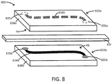
- an aerosol delivery device can comprise: a housing; an aerosol precursor liquid; a first heater having a heating surface; a second heater having a heating surface; and a liquid transport element having at least one end in a wicking arrangement with the aerosol precursor liquid; and the first heater and the second heater can be aligned in a substantially parallel arrangement with a portion of the fluid transport element positioned therebetween.
- the aerosol delivery device may be defined by one or more further characteristics, the following statements being exemplary thereof and being combinable in any manner.
- the aerosol precursor liquid can be physically separated from the first heater and the second heater by at least one wall.
- the at least one wall can at least partially define a chamber storing the aerosol precursor liquid.
- the chamber storing the aerosol precursor liquid can be substantially annularly arranged relative to the housing.
- the chamber storing the aerosol precursor liquid can be refillable.
- At least one wall physically separating the aerosol precursor liquid from the first heater and the second heater can include at least one aperture through which the at least one end of the liquid transport element extends.
- the at least one aperture can include a leak resistive gasket.
- the first heater and the second heater can be arranged apart so as to define an aerosol forming space therebetween.
- the device can include and airflow path through the housing, said airflow path extending through a space defined between the first heater and the second heater and to an aerosol outlet of the housing.
- the device further can comprise one or more of a controller, a power source, and a flow sensor.
- the aerosol delivery device further can comprise a second housing that is connectable with the housing, and wherein one or more of the controller, power source, and flow sensor is positioned in the second housing.
- the present disclosure can provide an atomizer for an aerosol delivery device.
- the atomizer can comprise a radiation-trapping chamber formed of a chamber wall, a radiation source positioned within the radiation-trapping chamber, and a wick, at least a portion of which is positioned within the radiation-trapping chamber so as to be in a vaporizing arrangement with the heater.
- the atomizer may be defined by one or more further characteristics, the following statements being exemplary thereof and being combinable in any manner.
- the radiation-trapping chamber can be substantially spherical.
- the radiation-trapping chamber can be substantially elongated (e.g., may be substantially tubular).
- An interior of the radiation-trapping chamber (e.g., an interior surface of the wall forming the chamber or a surface of a wall within the chamber) can be configured to one or more of absorb, emit, and reflect radiation from the radiation source.
- the interior of the radiation-trapping chamber can be configured as a black body.
- the interior of the radiation-trapping chamber can be configured as a white body.
- the radiation source can comprise a laser diode.
- the radiation source can comprise a resistive heating wire.
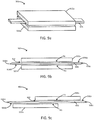
- an atomizer for an aerosol forming device can comprise: a first heater having a heating surface; a second heater having a heating surface; and a liquid transport element; and the first heater and the second heater can be aligned in a substantially parallel arrangement with the fluid transport element positioned therebetween.
- the atomizer may be defined by one or more further characteristics, the following statements being exemplary thereof and being combinable in any manner.
- the first heater and the second heater can be spaced apart with the respective heating surfaces facing each other.
- the liquid transport element may expressly not be in direct contact with either of the first heater and the second heater.
- the first heater and the second heater can have a substantially flattened shape.
- the first heater and the second heater each can comprise a substrate with a heating trace on a surface so as to define the heating surface. If desired, the heating surface of each of the first heater and the second heater further can comprises a passivating layer over the heater trace.
- the liquid transport element can comprise a ceramic material.
- the liquid transport element can comprise a fibrous material.
- the liquid transport element can comprise a rigid porous structure that contains an open pore network (i.e., porous glass, sintered porous glass beads, sintered porous ceramic beads, porous carbon, or graphite).
- an open pore network i.e., porous glass, sintered porous glass beads, sintered porous ceramic beads, porous carbon, or graphite.
- the liquid transport element can comprise opposing ends.
- at least one of the opposing ends of the liquid transport element can extend away from the first heater and the second heater so as to not be in a heating arrangement with the first heater and the second heater.
- the atomizer can further comprise an atomizer housing formed of at least one wall enclosing the first heater element and the second heater element.
- the atomizer housing can comprises at least one aperture through which the liquid transport element extends.
- the atomizer housing can include a leak resistive gasket at the at least one aperture.
- the atomizer housing can comprise an air inlet and an aerosol outlet.
- the present disclosure can relate to methods of forming an aerosol delivery device.
- such method can comprise inserting an atomizer into an outer shell, the atomizer comprising a radiation-trapping chamber and a heater configured to provide electromagnetic radiation.
- the atomizer further can comprise a wick, which may pass through an aperture into the radiation-trapping chamber and/or which may substantially line an interior surface of the chamber, such as an interior surface of the wall forming the radiation-trapping chamber.
- the method can comprise establishing an electrical connection between the heater and one or more electrical contacts.
- the electrical contacts may be configured to provide electrical connection between the heater and a power source, which may be positioned within the outer shell or may be positioned within a separate control body, which may be connectable to the outer shell so as to form the electrical connection.
- the method may comprise inserting a reservoir within the outer shell such that the wick is in fluid communication with an aerosol precursor composition stored within the reservoir.
- the disclosure can relate to methods of forming a vapor for inhalation.
- such method can comprise: supplying an aerosol precursor liquid along a liquid transport element, a portion of the liquid transport element being positioned between a first heater and a second heater that are aligned in a substantially parallel arrangement; and providing power to the first heating element and the second heating element sufficient to cause the first heater and the second heater to heat and vaporize at least a portion of the aerosol precursor liquid supplied along the liquid transport element.
- the method may be defined by one or more further characteristics, the following statements being exemplary thereof and being combinable in any manner.
- the first heater and the second heater can be spaced apart so as to define an aerosolization space therebetween, the liquid transport element being positioned within the aerosolization space, and wherein the liquid transport element is not in physical contact with either of the first heater and the second heater.
- the heating of the aerosol precursor liquid supplied along the liquid transport element can be substantially only by radiant heating from the first heater and the second heater.
- the invention includes, without limitation, the following embodiments:
- Aerosol delivery systems use electrical energy to heat a material (preferably without combusting the material to any significant degree and/or without significant chemical alteration of the material) to form an inhalable substance; and components of such systems have the form of articles that most preferably are sufficiently compact to be considered hand-held devices. That is, use of components of preferred aerosol delivery systems does not result in the production of smoke - i.e., from by-products of combustion or pyrolysis of tobacco, but rather, use of those preferred systems results in the production of vapors resulting from volatilization or vaporization of certain components incorporated therein.
- components of aerosol delivery systems may be characterized as electronic cigarettes, and those electronic cigarettes most preferably incorporate tobacco and/or components derived from tobacco, and hence deliver tobacco derived components in aerosol form.
- Aerosol generating pieces of certain preferred aerosol delivery systems may provide many of the sensations (e.g., inhalation and exhalation rituals, types of tastes or flavors, organoleptic effects, physical feel, use rituals, visual cues such as those provided by visible aerosol, and the like) of smoking a cigarette, cigar, or pipe that is employed by lighting and burning tobacco (and hence inhaling tobacco smoke), without any substantial degree of combustion of any component thereof.
- an aerosol generating piece of the present disclosure can be held and used much like a smoker employs a traditional type of smoking article, drawing on one end for inhalation of aerosol produced by that piece, taking or drawing puffs at selected intervals of time, and the like.
- Aerosol delivery devices of the present disclosure also can be characterized as being vapor-producing articles or medicament delivery articles.
- articles or devices can be adapted so as to provide one or more substances (e.g., flavors and/or pharmaceutical active ingredients) in an inhalable form or state.
- substances e.g., flavors and/or pharmaceutical active ingredients
- inhalable substances can be substantially in the form of a vapor (i.e., a substance that is in the gas phase at a temperature lower than its critical point).
- inhalable substances can be in the form of an aerosol (i.e., a suspension of fine solid particles or liquid droplets in a gas).
- aerosol as used herein is meant to include vapors, gases, and aerosols of a form or type suitable for human inhalation, whether or not visible, and whether or not of a form that might be considered to be smoke-like.
- Aerosol delivery devices of the present disclosure generally include a number of components provided within an outer body or shell, which may be referred to as a housing.
- the overall design of the outer body or shell can vary, and the format or configuration of the outer body that can define the overall size and shape of the aerosol delivery device can vary.
- an elongated body resembling the shape of a cigarette or cigar can be a formed from a single, unitary housing, or the elongated housing can be formed of two or more separable bodies.
- an aerosol delivery device can comprise an elongated shell or body that can be substantially tubular in shape and, as such, resemble the shape of a conventional cigarette or cigar. In one embodiment, all of the components of the aerosol delivery device are contained within one housing.
- an aerosol delivery device can comprise two or more housings that are joined and are separable.
- an aerosol delivery device can possess at one end a control body comprising a housing containing one or more components (e.g., a battery and various electronics for controlling the operation of that article), and at the other end and removably attached thereto an outer body or shell containing aerosol forming components (e.g., one or more aerosol precursor components, such as flavors and aerosol formers, one or more heaters, and/or one or more wicks).
- one or more components e.g., a battery and various electronics for controlling the operation of that article
- aerosol forming components e.g., one or more aerosol precursor components, such as flavors and aerosol formers, one or more heaters, and/or one or more wicks.
- Aerosol delivery devices of the present disclosure can be formed of an outer housing or shell that is not substantially tubular in shape but may be formed to substantially greater dimensions.
- the housing or shell can be configured to include a mouthpiece and/or may be configured to receive a separate shell (e.g., a cartridge) that can include consumable elements, such as a liquid aerosol former, and can include a vaporizer or atomizer.
- Aerosol delivery devices of the present disclosure most preferably comprise some combination of a power source (i.e., an electrical power source), at least one control component (e.g., means for actuating, controlling, regulating and ceasing power for heat generation, such as by controlling electrical current flow the power source to other components of the article - e.g., a microcontroller or microprocessor), a heater or heat generation member (e.g., an electrical resistance heating element or other component, which alone or in combination with one or more further elements may be commonly referred to as an "atomizer”), an aerosol precursor composition (e.g., commonly a liquid capable of yielding an aerosol upon application of sufficient heat, such as ingredients commonly referred to as "smoke juice,” “e-liquid” and “e-juice”), and a mouthpiece or mouth region for allowing draw upon the aerosol delivery device for aerosol inhalation (e.g., a defined airflow path through the article such that aerosol generated can be withdrawn therefrom upon draw).
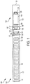
- the aerosol delivery device 100 can comprise a control body 102 and a cartridge 104 that can be permanently or detachably aligned in a functioning relationship. Engagement of the control body 102 and the cartridge 104 can be press fit (as illustrated), threaded, interference fit, magnetic, or the like.
- connection components such as further described herein may be used.
- the control body may include a coupler that is adapted to engage a connector on the cartridge.
- control body 102 and the cartridge 104 may be referred to as being disposable or as being reusable.
- the control body may have a replaceable battery or a rechargeable battery and thus may be combined with any type of recharging technology, including connection to a typical electrical outlet, connection to a car charger (i.e., cigarette lighter receptacle), and connection to a computer, such as through a universal serial bus (USB) cable.
- USB universal serial bus
- an adaptor including a USB connector at one end and a control body connector at an opposing end is disclosed in U.S. Pat. Pub. No. 2014/0261495 to Novak et al. , which is incorporated herein by reference in its entirety.
- the cartridge may comprise a single-use cartridge, as disclosed in U.S. Pat. No. 8,910,639 to Chang et al. , which is incorporated herein by reference in its entirety.
- a control body 102 can be formed of a control body shell 101 that can include a control component 106 (e.g., a printed circuit board (PCB), an integrated circuit, a memory component, a microcontroller, or the like), a flow sensor 108, a battery 110, and an LED 112, and such components can be variably aligned. Further indicators (e.g., a haptic feedback component, an audio feedback component, or the like) can be included in addition to or as an alternative to the LED. Additional representative types of components that yield visual cues or indicators, such as light emitting diode (LED) components, and the configurations and uses thereof, are described in U.S. Pat. Nos.
- LED light emitting diode
- a cartridge 104 can be formed of a cartridge shell 103 enclosing the reservoir 144 that is in fluid communication with a liquid transport element 136 adapted to wick or otherwise transport an aerosol precursor composition stored in the reservoir housing to a heater 134.
- a liquid transport element can be formed of one or more materials configured for transport of a liquid, such as by capillary action.
- a liquid transport element can be formed of, for example, fibrous materials (e.g., organic cotton, cellulose acetate, regenerated cellulose fabrics, glass fibers), porous ceramics, porous carbon, graphite, porous glass, sintered glass beads, sintered ceramic beads, capillary tubes, or the like.
- the liquid transport element thus can be any material that contains an open pore network (i.e., a plurality of pores that are interconnected so that fluid may flow from one pore to another in a plurality of direction through the element).
- an open pore network i.e., a plurality of pores that are interconnected so that fluid may flow from one pore to another in a plurality of direction through the element.
- materials configured to produce heat when electrical current is applied therethrough may be employed to form the resistive heating element 134.
- Example materials from which the wire coil may be formed include Kanthal (FeCrAl), Nichrome, Molybdenum disilicide (MoSi 2 ), molybdenum silicide (MoSi), Molybdenum disilicide doped with Aluminum (Mo(Si,Al) 2 ), titanium, platinum, silver, palladium, graphite and graphite-based materials (e.g., carbon-based foams and yarns) and ceramics (e.g., positive or negative temperature coefficient ceramics).
- a heater may comprise materials configured to provide electromagnetic radiation, including laser diodes.
- An opening 128 may be present in the cartridge shell 103 (e.g., at the mouthend) to allow for egress of formed aerosol from the cartridge 104.
- Such components are representative of the components that may be present in a cartridge and are not intended to limit the scope of cartridge components that are encompassed by the present disclosure.
- the cartridge 104 also may include one or more electronic components 150, which may include an integrated circuit, a memory component, a sensor, or the like.
- the electronic component 150 may be adapted to communicate with the control component 106 and/or with an external device by wired or wireless means.
- the electronic component 150 may be positioned anywhere within the cartridge 104 or its base 140.
- control component 106 and the flow sensor 108 are illustrated separately, it is understood that the control component and the flow sensor may be combined as an electronic circuit board with the air flow sensor attached directly thereto. Further, the electronic circuit board may be positioned horizontally relative the illustration of FIG. 1 in that the electronic circuit board can be lengthwise parallel to the central axis of the control body.
- the air flow sensor may comprise its own circuit board or other base element to which it can be attached.
- a flexible circuit board may be utilized. A flexible circuit board may be configured into a variety of shapes, include substantially tubular shapes.
- the control body 102 and the cartridge 104 may include components adapted to facilitate a fluid engagement therebetween.
- the control body 102 can include a coupler 124 having a cavity 125 therein.
- the cartridge 104 can include a base 140 adapted to engage the coupler 124 and can include a projection 141 adapted to fit within the cavity 125. Such engagement can facilitate a stable connection between the control body 102 and the cartridge 104 as well as establish an electrical connection between the battery 110 and control component 106 in the control body and the heater 134 in the cartridge.
- control body shell 101 can include an air intake 118, which may be a notch in the shell where it connects to the coupler 124 that allows for passage of ambient air around the coupler and into the shell where it then passes through the cavity 125 of the coupler and into the cartridge through the projection 141.
- an air intake 118 which may be a notch in the shell where it connects to the coupler 124 that allows for passage of ambient air around the coupler and into the shell where it then passes through the cavity 125 of the coupler and into the cartridge through the projection 141.
- a coupler as seen in FIG. 1 may define an outer periphery 126 configured to mate with an inner periphery 142 of the base 140.
- the inner periphery of the base may define a radius that is substantially equal to, or slightly greater than, a radius of the outer periphery of the coupler.
- the coupler 124 may define one or more protrusions 129 at the outer periphery 126 configured to engage one or more recesses 178 defined at the inner periphery of the base.
- connection between the base 140 of the cartridge 104 and the coupler 124 of the control body 102 may be substantially permanent, whereas in other embodiments the connection therebetween may be releasable such that, for example, the control body may be reused with one or more additional cartridges that may be disposable and/or refillable.
- the aerosol delivery device 100 may be substantially rod-like or substantially tubular shaped or substantially cylindrically shaped in some embodiments. In other embodiments, further shapes and dimensions are encompassed - e.g., a rectangular or triangular cross-section, multifaceted shapes, or the like.
- the reservoir 144 illustrated in FIG. 1 can be a container or can be a fibrous reservoir, as presently described.
- the reservoir 144 can comprise one or more layers of nonwoven fibers substantially formed into the shape of a tube encircling the interior of the cartridge shell 103, in this embodiment.
- An aerosol precursor composition can be retained in the reservoir 144.
- Liquid components for example, can be sorptively retained by the reservoir 144.
- the reservoir 144 can be in fluid connection with a liquid transport element 136.
- the liquid transport element 136 can transport the aerosol precursor composition stored in the reservoir 144 via capillary action to the heating element 134 that is in the form of a metal wire coil in this embodiment. As such, the heating element 134 is in a heating arrangement with the liquid transport element 136.
- the heating element 134 is activated, and the components for the aerosol precursor composition are vaporized by the heating element 134.
- Drawing upon the mouthend of the article 100 causes ambient air to enter the air intake 118 and pass through the cavity 125 in the coupler 124 and the central opening in the projection 141 of the base 140.
- the drawn air combines with the vapor to form an aerosol.
- the aerosol is whisked, aspirated, or otherwise drawn away from the heating element 134 and out the mouth opening 128 in the mouthend of the article 100.
- An input element may be included with the aerosol delivery device.
- the input may be included to allow a user to control functions of the device and/or for output of information to a user.
- Any component or combination of components may be utilized as an input for controlling the function of the device.
- one or more pushbuttons may be used as described in U.S. Pat. App. Ser. No. 14/193,961, filed February 28, 2014, to Worm et al. , which is incorporated herein by reference.
- a touchscreen may be used as described in U.S. Pat. App. Ser. No. 14/643,626, filed March 10, 2015, to Sears et al. , which is incorporated herein by reference.
- components adapted for gesture recognition based on specified movements of the aerosol delivery device may be used as an input. See U.S. Pat. App. Ser. No. 14/565,137, filed December 9, 2014, to Henry et al. , which is incorporated herein by reference.
- an input may comprise a computer or computing device, such as a smartphone or tablet.
- the aerosol delivery device may be wired to the computer or other device, such as via use of a USB cord or similar protocol.
- the aerosol delivery device also may communicate with a computer or other device acting as an input via wireless communication. See, for example, the systems and methods for controlling a device via a read request as described in U.S. Pat. App. Ser. No. 14/327,776, filed July 10, 2014, to Ampolini et al. , the disclosure of which is incorporated herein by reference.
- an APP or other computer program may be used in connection with a computer or other computing device to input control instructions to the aerosol delivery device, such control instructions including, for example, the ability to form an aerosol of specific composition by choosing the nicotine content and/or content of further flavors to be included.
- an aerosol delivery device can be chosen from components described in the art and commercially available.
- Examples of batteries that can be used are described in U.S. Pat. Pub. No. 2010/0028766 to Peckerar et al. , the disclosure of which is incorporated herein by reference in its entirety.
- the aerosol delivery device can incorporate a sensor or detector for control of supply of electric power to the heat generation element when aerosol generation is desired (e.g., upon draw during use).
- a sensor or detector for control of supply of electric power to the heat generation element when aerosol generation is desired (e.g., upon draw during use).
- Additional representative types of sensing or detection mechanisms, structure and configuration thereof, components thereof, and general methods of operation thereof, are described in U.S. Pat. Nos. 5,261,424 to Sprinkel, Jr. ; 5,372,148 to McCafferty et al. ; and PCT WO 2010/003480 to Flick ; which are incorporated herein by reference.
- the aerosol delivery device most preferably incorporates a control mechanism for controlling the amount of electric power to the heat generation element during draw.
- Representative electronic components, structure and configuration thereof, features thereof, and general methods of operation thereof, are described in U.S. Pat. Nos. 4,735,217 to Gerth et al. ; 4,947,874 to Brooks et al. ; 5,372,148 to McCafferty et al. ; 6,040,560 to Fleischhauer et al. ; 7,040,314 to Nguyen et al. and 8,205,622 to Pan ; U.S. Pat. Pub. Nos. 2009/0230117 to Fernando et al. , 2014/0060554 to Collet et al. , and 2014/0270727 to Ampolini et al. ; and U.S. Pat. App. Ser. No. 14/209,191, filed March 13, 2014, to Henry et al. ; which are incorporated herein by reference
- the aerosol precursor composition most preferably incorporates tobacco or components derived from tobacco.
- the tobacco may be provided as parts or pieces of tobacco, such as finely ground, milled or powdered tobacco lamina.
- the tobacco may be provided in the form of an extract, such as a spray dried extract that incorporates many of the water soluble components of tobacco.
- tobacco extracts may have the form of relatively high nicotine content extracts, which extracts also incorporate minor amounts of other extracted components derived from tobacco.
- components derived from tobacco may be provided in a relatively pure form, such as certain flavoring agents that are derived from tobacco.
- a component that is derived from tobacco, and that may be employed in a highly purified or essentially pure form is nicotine (e.g., pharmaceutical grade nicotine).
- the aerosol precursor composition also referred to as a vapor precursor composition, may comprise a variety of components including, by way of example, a polyhydric alcohol (e.g., glycerin, propylene glycol, or a mixture thereof), nicotine, tobacco, tobacco extract, and/or flavorants.
- a polyhydric alcohol e.g., glycerin, propylene glycol, or a mixture thereof
- nicotine tobacco, tobacco extract, and/or flavorants.
- Representative types of aerosol precursor components and formulations also are set forth and characterized in U.S. Pat. No. 7,217,320 to Robinson et al. and U.S. Pat. Pub. Nos. 2013/0008457 to Zheng et al. ; 2013/0213417 to Chong et al. ; 2014/0060554 to Collett et al. ; 2015/0020823 to Lipowicz et al.
- aerosol precursors that may be employed include the aerosol precursors that have been incorporated in the VUSE® product by R. J. Reynolds Vapor Company, the BLUTM product by Lorillard Technologies, the MISTIC MENTHOL product by Mistic Ecigs, and the VYPE product by CN Creative Ltd. Also desirable are the so-called "smoke juices" for electronic cigarettes that have been available from Johnson Creek Enterprises LLC.
- the amount of aerosol precursor that is incorporated within the aerosol delivery system is such that the aerosol generating piece provides acceptable sensory and desirable performance characteristics.
- sufficient amounts of aerosol forming material e.g., glycerin and/or propylene glycol
- the amount of aerosol precursor within the aerosol generating system may be dependent upon factors such as the number of puffs desired per aerosol generating piece.
- the amount of aerosol precursor incorporated within the aerosol delivery system, and particularly within the aerosol generating piece is less than about 2 g, generally less than about 1.5 g, often less than about 1 g and frequently less than about 0.5 g.
- the present disclosure can relate to atomizers and elements thereof that may be utilized in an aerosol delivery device.
- Such atomizers and elements thereof can be particularly beneficial for improved energy efficiency in an aerosol delivery device. For example, energy drain associated with achieving the desired heating temperature between puffs on a device can be minimized. More particularly, the atomizers and associated elements can achieve the desired heating temperature more rapidly and/or reduce heat losses that may hinder vaporization.
- the heater used in an atomizer can be a source of electromagnetic radiation.
- the heater can be configured to emit electromagnetic radiation of a specific wavelength or a specific range of wavelengths (i.e., a defined band).
- the heater can be configured to emit electromagnetic radiation having a wavelength that is within the range that encompasses violet light to far infrared light. More particularly, the wavelength can be within the range of about 390 nm to about 1 mm. As another example, the wavelength can be within the range that encompasses visible light (i.e., about 400 nm to about 700 nm).
- the radiation source may be configured to emit radiation with a focused band, and such focused band may be chosen based upon the substrate to be heated so as to maximize the heating of the specific substrate(s).
- the radiation source can be configured to emit electromagnetic radiation within a wavelength band having a bandwidth that is no greater than 100 ⁇ m, that is no greater than 10 ⁇ m, no greater than 1,000 nm, that is no greater than 500 nm, that is no greater than 250 nm, that is no greater than 100 nm, that is no greater than 50 nm, that is no greater than 10 nm, that is no greater than 5 nm, or that is no greater than 2 nm.
- the radiation source can be configured to emit electromagnetic radiation within a range corresponding to a particular absorption wavelength of a wick material, of an aerosol precursor composition, and/or of one or more specific components of an aerosol precursor composition.
- a particular absorption wavelength of a wick material, of an aerosol precursor composition can exhibit preferential absorption in a wavelength band of about 2 ⁇ m to about 12 ⁇ m.
- a heater according to the present disclosure may be configured to emit electromagnetic radiation within a wavelength band that is no greater than 10 ⁇ m (i.e., having specific wavelengths in the range of 2 ⁇ m to 12 ⁇ m). Other ranges, however, are encompassed.
- a wavelength band of about 700 nm to about 1 mm may be beneficial for specific absorbance of electromagnetic energy of visible by a material that is visibly clear but is opaque in relation to infrared light.
- a wavelength band of about 390 nm to about 790 nm may be beneficial for specific absorbance by a substrate that is visibly black.
- a laser diode may be used as the heater.
- Utilization of radiation of a specific wavelength or very narrow band can focus the energy spectrally so that less energy is spread out to various wavelengths.
- Radiation wavelength can be tuned to a specific absorption wavelength (or band) of a substrate, such as an aerosol precursor composition or component thereof and/or a wick from which the aerosol precursor composition may be vaporized.
- Use of a laser-based radiation source also can be advantageous for focusing the radiation energy into a smaller space-domain to minimize radiation losses.
- An atomizer according to the present disclosure can be defined in some embodiments by a chamber within which the radiation is emitted and from which vaporized aerosol precursor composition may be released.
- the chamber may be reduced in size because of the ability to focus the radiation energy and avoid energy losses.
- the desired amount of vapor may be produced from a smaller volume since less energy is wasted.
- a laser radiation source can provide direct heating of an aerosol precursor composition.
- a device may be configured such that aerosol precursor composition is delivered (including via wicking) to a specific location (i.e., a vaporization target) within a chamber, and one or more laser radiation sources can be focused directly at the specific location.
- the laser radiation band is focused to a preferred absorption wavelength of the target (i.e., the target substrate and/or the aerosol precursor material), such focused heating may be particularly beneficial for increasing vapor formation while reducing energy requirements.
- the chamber may take on a variety of shapes.
- the chamber may be substantially spherical. Multifaceted structures may also be utilized.
- the chamber may be substantially elongated (e.g., tubular). Chamber shape (optionally in combination with the airflow path through and/or around the chamber) can enhance not only the energy absorption but also vapor elution.
- the chamber can, in some embodiments, be a radiation-trapping chamber.
- the chamber preferentially is configured to maximize the capture and/or release of incident radiation on the chamber walls.
- the interior of the wall(s) forming the chamber can be configured to one or more of absorb, emit, and reflect radiation from the radiation source.
- the interior of the chamber wall(s) may be configured to absorb at least about 50%, at least about 60%, at least about 70%, or at least about 80% of all incident electromagnetic radiation; the interior of the chamber wall(s) may be configured to reflect at least about 50%, at least about 60%, at least about 70%, or at least about 80% of all incident electromagnetic radiation.
- the interior of the chamber wall can be configured as a black body.
- the black body construction can indicate that substantially all of the incident electromagnetic radiation is absorbed, regardless of frequency or angle of incidence.
- the ability of the black body construction to absorb substantially all of the incident electromagnetic radiation can mean that at least 98%, at least 99%, at least 99.5%, or at least 99.9% of all incident electromagnetic radiation is absorbed.
- the black body construction further can indicate that it is an ideal emitter (i.e., at every frequency, it emits as much (or more) energy as any other body at the same temperature) and/or that it is a diffuse emitter (i.e., the energy is radiated isotropically, independent of direction).
- a black body in thermal equilibrium can emit electromagnetic radiation - i.e., black-body radiation. Such radiation is emitted having a spectrum that is determined by temperature and not by the shape or composition of the black body structure.
- a radiation-trapping chamber thus may be constructed of a material having an emissivity that is close to 1.
- emissivity of a radiation trapping chamber configured substantially as a black body can be greater than 0.5, greater than 0.6, greater than 0.7, greater than 0.8, or greater than 0.9, such as, for example, about 0.6 to about 0.99, about 0.7 to about 0.98, or about 0.75 to about 0.95.
- the interior of the chamber wall can be configured as a white body.
- the interior of the chamber wall can be configured to reflect substantially all incident electromagnetic radiation completely and uniformly in all directions.
- the ability to reflect substantially all incident electromagnetic radiation can mean that at least 98%, at least 99%, at least 99.5%, or at least 99.9% of all incident electromagnetic radiation is reflected.
- Emissivity of a radiation trapping chamber configured substantially as a white body can be less than 0.5, less than 0.4, less than 0.3, less than 0.2, or less than 0.1, such as, for example, in the range of about 0.01 to about 0.4, about 0.02 to about 0.3, or about 0.05 to about 0.25.
- a radiation trapping chamber may be formed of any material that is sufficiently heat stable at the temperatures achieved within the chamber.
- the radiation-trapping chamber particularly may include an out, insulating layer so as to substantially prevent or reduce radiation of heat away from the chamber.
- materials that may be useful in forming a radiation-trapping chamber can include ceramics and silicon-based materials.
- a double-walled chamber may be utilized such that an insulating material (including air) may be present between the walls.
- the radiation source utilized as the heater can be configured to provide radiation within the chamber, particularly a radiation-trapping chamber.
- the radiation source may be positioned on the wall of the chamber (i.e., attached directly thereto or incorporated therein) so as to emit the radiation directly within the chamber.
- the radiation source can be positioned within the chamber and spaced apart from the chamber wall.
- one or more struts or supports may extend through or from the chamber wall so that the radiation source is substantially suspended within the chamber.
- the radiation source may be substantially centered within the chamber or may be off-set from the approximate center of the chamber.
- the radiation source can extend substantially along a longitudinal axis through the chamber and/or through the shell of the device in which the chamber and radiation source are positioned.
- the chamber can include at least one opening (or outlet) through which formed vapor may escape or be expelled.
- the chamber also can include an inlet into which air or another gas may pass so as to entrain or co-mingle with formed vapor and exit through the outlet.
- the inlet and the outlet can be in fluid communication.
- the chamber may include one or more further openings, apertures, or the like through which additional elements of an atomizer and/or aerosol delivery device may pass.
- the further openings may also allow for influx of air.
- the further openings may be substantially sealed.
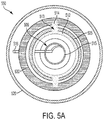
- an atomizer 201 comprises a chamber 203 (preferably a radiation-trapping chamber) that is substantially spherical (although other shapes are also encompassed).
- the chamber 203 is illustrated partially transparent for ease of description thereof.
- the chamber 203 is formed of a chamber wall 205 with an interior surface 205a and an exterior surface 205b.
- the interior surface 205a may be configured as a black body or a white body as otherwise described herein so as to enable configuration as a radiation-trapping chamber.
- the chamber 203 also includes apertures 211 through which a wick (not illustrated) may be inserted. Although two apertures 211 are illustrated, only a single aperture may be used, or more than two apertures may be used (i.e., for insertion of multiple wicks).
- Laser diodes 215 are also present and are positioned in the wall 205 of the chamber 203 so as to emit electromagnetic radiation into the interior 203a of the chamber 203.
- FIG. 2b A cross-section of the atomizer 201 from FIG. 2a is shown in FIG. 2b .
- a wick 212 is shown passing through the apertures 211 so that a portion of the wick is interior to the chamber 203 and a portion of the wick is exterior to the chamber.
- the wick 212 can transport an aerosol precursor composition to the interior 203a of the chamber 203 so that electromagnetic radiation from the laser diode 215 can be utilized to vaporize the aerosol precursor composition to pass out of the chamber, particularly combined with air entering the chamber through the inlet 207, through the outlet 209 (e.g., as an aerosol).
- FIG. 2c and FIG. 2d A further exemplary embodiment of an atomizer 201 is shown in FIG. 2c and FIG. 2d .
- a substantially spherical chamber 203 is formed of a chamber wall 205 having an interior surface 205a and an exterior surface 205b, and laser diodes 215 are positioned in the chamber wall along with an inlet 207 and an outlet 209.
- the wick 212 is present substantially in the form of a sheet lining the interior surface 205a of the chamber wall 205.
- the wick 212 in particular, is in a curved, planar form.
- the chamber 203 also includes a channel 213 passing therethrough from the interior of the chamber to the exterior of the chamber.
- the channel 213 is substantially at the "equator" of the sphere and extends around the entire circumference thereof so as to essentially divide the chamber 203 into two hemispheres.
- a wick extension 214 protrudes through the channel 213 so as to be in fluid communication with the exterior environment surrounding the chamber 203. As further illustrated herein, the wick extension 214 may contact a reservoir to transport the aerosol precursor composition therefrom into the interior of the chamber 203 to "wet" the wick lining. Electromagnetic radiation from the laser diodes 215 may penetrate the wick lining 212 to facilitate the radiation-trapping effect described herein and vaporize the aerosol precursor composition in the wick.
- the chamber can take on other configurations.
- the chamber may be substantially elongated.
- the electromagnetic radiation source can take on further configurations.
- a heating wire may be used.
- FIG. 3 An aerosol delivery device 350 including a chamber 303 and an electromagnetic radiation source 315 is shown in FIG. 3 .
- the chamber 303 is again substantially spherical; however, other chamber configurations are also encompassed, as described in greater detail below.
- the aerosol delivery device 350 comprises an outer shell 320 in which further portions of the device are positioned.
- the chamber 303 comprises a chamber wall 305 with an interior surface 305a and an exterior surface 305b.
- Laser diodes 315 are positioned in the chamber wall 305 and configured to emit radiation within the chamber 303.
- the interior surface 305a of the chamber wall 305 is configured to trap emitted radiation as otherwise described herein.
- a wick 312 is positioned such that a portion of the wick is interior to the chamber 303 and a portion of the wick is exterior to the chamber.
- one or more wick arm(s) 312a are exterior to the chamber 303 and are in contact with a reservoir 330 which, as illustrated, is a porous substrate, such as a fibrous mat (although other reservoir configurations and materials are also encompassed).
- the reservoir 330 wraps around the interior of the outer shell 320. Contact between the wick 312 and the reservoir 330 is sufficient such that an aerosol precursor composition held by the reservoir may pass to the wick for transport to the chamber 303.
- the chamber 303 includes an inlet 307 through which air may enter and an outlet 309 through which formed aerosol may exit.
- the aerosol delivery device 350 comprises an air entry 352 and an aerosol port 354 at opposing ends thereof. Air passing into the aerosol delivery device 350 through the air entry 352 is directed to the inlet 307 of the chamber by an air passage 353a defined by an air passage wall 353b that extends between the air entry and the inlet 307.
- the air passage wall 353b is configured such that the air passage 353a is substantially conical so as taper toward the inlet 307 of the chamber 303 and improve focusing of the incoming air into the chamber.
- aerosol formed in the chamber 303 through mixing of the air and vaporized aerosol precursor composition passes through the outlet 309 to the aerosol port 354.
- An aerosol passage 355a is defined by an aerosol passage wall 355b that extends between the outlet 309 and the aerosol port 354.
- the aerosol passage is substantially linear; however, other embodiments are also encompassed.
- the aerosol port 354 is positioned at a mouth end 360 of the aerosol delivery device 350, and the aerosol port 354 may particularly be defined in a mouth end cap 361.
- the aerosol delivery device 350 is shown in FIG. 3 relative to its x axis, y axis, and z axis. To further illustrate the device 350, FIG. 3a shows a cross-section thereof through the xy plane, and FIG. 3b shows a cross-section thereof through the xz plane.
- FIG. 4 A further example embodiment of an aerosol delivery device 450 is shown in FIG. 4 .
- the aerosol delivery device 450 again includes a chamber 403 and an electromagnetic radiation source 415.
- the chamber 403 is again substantially spherical; however, other chamber configurations are also encompassed.
- the aerosol delivery device 450 comprises an outer shell 420 in which further portions of the device are positioned.
- the chamber 403 comprises a chamber wall 405 with an interior surface (which is obscured in the illustration by the wick 412 that substantially lines the interior of the chamber wall) and an exterior surface 405b.
- Laser diodes 415 are positioned in the chamber wall 405 and configured to emit radiation within the chamber 403.
- a wick 412 is present in substantially the form of a sheet lining the interior surface of the chamber wall 405.
- the chamber 403 is formed so as to include a channel 413 passing through the wall 405 thereof from the interior of the chamber to the exterior of the chamber.
- the channel 413 is substantially at the "equator" of the sphere and extends around the entire circumference thereof so as to essentially divide the chamber 403 into two hemispheres.
- a wick extension 414 protrudes through the channel 413 so as to be in fluid communication with the exterior environment surrounding the chamber 403.
- the wick extension 414 is in fluid connection with the reservoir 430 in which the aerosol precursor composition is stored.
- the interior surface of the chamber wall 405 is configured to trap emitted radiation as otherwise described herein.
- the structure of the wick 412 is configured so that radiation may pass therethrough for interaction with the interior surface of the chamber wall 405.
- the chamber 403 includes an inlet 407 through which air may enter and an outlet 409 through which formed aerosol may exit.
- the aerosol delivery device 450 comprises an air entry 452 and an aerosol port 454 at opposing ends thereof. Air passing into the aerosol delivery device 450 through the air entry 452 is directed to the inlet 407 of the chamber 403 by an air passage 453a defined by an air passage wall 453b that extends between the air entry and the inlet 307. Aerosol formed in the chamber 403 passes through the outlet 409 to the aerosol port 454.
- An aerosol passage 455a is defined by an aerosol passage wall 455b that extends between the outlet 409 and the aerosol port 454.
- the aerosol port 454 is positioned at a mouth end 460 of the aerosol delivery device 450, and the aerosol port may particularly be defined in a mouth end cap 461.
- the aerosol delivery device 550 includes a chamber 503 that is elongated (i.e., substantially tubular) and includes an electromagnetic radiation source 515 positioned within the chamber.
- the electromagnetic radiation source 515 is a coiled wire that can provide resistive heating; however, the wire may be provided in different configurations, and other types of electromagnetic radiation sources may be used.
- the electromagnetic radiation source 515 has respective ends that are connected to electrical connectors 516 that provide electrical connection to a power source.
- the aerosol delivery device 550 comprises an outer shell 520 in which further portions of the device are positioned.
- the chamber 503 comprises a chamber wall 505 with an interior surface (which is obscured in the illustration by the wick 512 that substantially lines the interior of the chamber wall) and an exterior surface 505b.
- a wick 512 is present in substantially the form of a sheet lining the interior surface of the chamber wall 505.
- the chamber 503 is formed so as to include a channel 513 passing through the wall 505 thereof from the interior of the chamber to the exterior of the chamber. See particularly the cross-section in FIG. 5a through the yz plane at approximately a longitudinal midpoint of the chamber 503.
- the channel 513 may pass through the chamber wall 505 at any location and is not limited to the two locations illustrated in FIG. 5a .
- a wick extension 514 protrudes through the channel 513 so as to be in fluid communication with the exterior environment surrounding the chamber 503.
- the wick extension 514 is in fluid connection with the reservoir 530 in which the aerosol precursor composition is stored.
- Contact between the wick 514 and the reservoir 530 is sufficient such that the aerosol precursor composition held by the reservoir may pass via the wick extension 514 to the wick 512 for distribution around the interior of the chamber 503.
- the interior surface of the chamber wall 505 is configured to trap emitted radiation as otherwise described herein.
- the structure of the wick 512 is configured so that radiation may pass therethrough for interaction with the interior surface of the chamber wall 505.
- the elongated chamber 503 includes an inlet 507 through which air may enter and an outlet 509 through which formed aerosol may exit.
- the aerosol delivery device 550 comprises an air entry 552 and an aerosol port 554 at opposing ends thereof. Air passing into the aerosol delivery device 550 through the air entry 552 is directed to the inlet 507 of the chamber 503 by an air passage 553a defined by an air passage wall 553b that extends between the air entry and the inlet 507. Aerosol formed in the chamber 503 passes through the outlet 509 to the aerosol port 554.
- An aerosol passage 555a is defined by an aerosol passage wall 555b that extends between the outlet 509 and the aerosol port 554.
- the aerosol port 554 is positioned at a mouth end 560 of the aerosol delivery device 550, and the aerosol port may particularly be defined in a mouth end cap 561.
- the heater is aligned substantially parallel to the longitudinal axis of the aerosol delivery device.
- heating of the wick in the chamber is carried out in the absence of any direct physical contact between the wick and a heater.
- heating may be substantially or completely radiative.
- radiative heating can be sufficient to heat a substrate (e.g., a wick) and/or an aerosol precursor material to a temperature of about 100°C to about 400°C, about 125°C to about 350°C, or about 150°C to about 300°C.
- radiative heating can be in a range that is above the vaporization temperature of a liquid aerosol precursor material but less than 300°C, less than 250°C, or less than 200°C.
- heating may be carried out using a combination of thermal conduction (i.e., direct contact of a heating source and a wick) as well as radiative heating. Utilizing combination heating can particularly be useful for improving efficiency.
- thermal conduction i.e., direct contact of a heating source and a wick
- radiative heating can particularly be useful for improving efficiency.
- the heat source may need to be heated to a greater temperature to sufficiently overcome the radiative heat losses and still heat the wick to the required vapor forming temperature.
- the heat that radiates away from the heat source may be directed back to the wick. As such, less power may be required to achieve the required vapor forming temperature.
- an aerosol delivery device 650 can be configured such that a heater 615 in the form of a heating wire is positioned within a chamber 603 and is wrapped around a wick 612 having a portion within the chamber and having wick arms 612a that are exterior to the chamber.
- the wick arms 612a are in fluid connection with the reservoir 630 so that aerosol precursor composition stored in the reservoir may pass through the wick into the chamber 603 where the aerosol precursor composition is heated and vaporized through conductive heating by being in direct contact with the heater 615 and through radiative heating by receiving the additional heat that radiates away from the heater but is returned to the wick because of the nature of the interior surface 605a of the wall 605 of the chamber 603.
- the aerosol delivery device 650 includes an outer shell 620, an air entry 652 and an aerosol port 654.
- the air entry 652 is positioned at a connecting end 656 of the aerosol delivery device 650, which may be configured for connection to a control body (see FIG. 1 ).
- the aerosol port 654 is positioned at a mouth end 660 of the aerosol delivery device 650 and is particularly formed in a mouth end cap 661. Air passing into the aerosol delivery device 650 through the air entry 652 is directed to the inlet 607 of the chamber 603 by an air passage 653a defined by an air passage wall 653b that extends between the air entry and the inlet.
- Aerosol formed in the chamber 603 passes through the outlet 609 to the aerosol port 654.
- An aerosol passage 655a is defined by an aerosol passage wall 655b that extends between the outlet 609 and the aerosol port 654.
- the wick portion within the chamber and the heater are aligned substantially perpendicular to the longitudinal axis of the aerosol delivery device.
- the present disclosure further can provide for methods of preparing an aerosol delivery device.
- Such methods can include combining an outer shell with a radiation-trapping chamber and/or combining an outer shell with a laser diode.
- a method of assembling an aerosol delivery device can comprise at least the step of inserting a radiation-trapping chamber into an outer shell.
- the assembly method further can comprise one or more of the following steps: combining a heater with the radiation-trapping chamber so that the heater is configured for providing electromagnetic radiation within the chamber; establishing an electrical connection between the heater and one or more electrical connectors in step such that the power may be delivered from a power source to the heater; inserting a wick into the chamber; placing a reservoir into the outer shell such that the wick is in fluid connection with the reservoir; and adding an end cap to a mouth end of the outer shell such that the mouth end is configured for exit of aerosol from the aerosol delivery device.
- the wick may be inserted into the chamber before or after the chamber is combined with the heater and/or before or after the chamber is inserted into the outer shell.
- the reservoir may be placed into the outer shell before or after inserting the chamber into the outer shell.
- a heater used according to the present disclosure can be a microheater.
- a microheater 733 as shown in FIG. 7 can comprise a substrate 738, a heater trace 734 on the substrate, and electrical terminals 735 to which the heater trace connects for making an electrical connection with a power source.
- the microheater further can comprise a passivating layer 739 atop the substrate 738 and substantially or completely covering the heater trace 734 and the electrical connectors 735.
- the passivating layer 739 is substantially transparent; however, the passivating layer may otherwise be translucent or opaque.
- the passivating layer 739 preferably is chemically and thermally stable and will not significantly reduce heat transfer from the heater trace 734 away from the microheater 733.
- the microheater 733 can be substantially flattened in shape.
- a substantially flattened element will have a thickness that is less than the length and less than the width of the element.
- a substantially flattened element also can have a thickness that is about 70% or less, about 60% or less, about 50% or less, about 40% or less, about 30% or less, or about 20% or less of one or both of the length and width of the element.
- the length and width of the microheater can each independently be about 1.5 mm to about 20 mm, about 2 mm to about 15 mm, about 2.5 mm to about 10 mm, or about 3 mm to about 8 mm.
- the length of the microheater can be greater than the width, and a lengthwise axis of the microheater can be substantially parallel to the lengthwise axis of an aerosol forming device in which the microheater is used.
- a lengthwise axis of the microheater can be substantially perpendicular to the lengthwise axis of an aerosol forming device in which the microheater is used. The substantially flattened nature of the microheater is further evident in relation to FIG. 8 , FIG. 9a, and FIG. 9b .
- a pair of heaters can be utilized for heating an aerosol precursor liquid.
- Each of the heaters in the pair can include a heating surface, and such heating surface particularly can be a substantially flattened surface.
- the heating surface may be referred to as a heating face, and the heating surface or face can have a defined area such as, for example, an area of about 3 mm 2 to about 400 mm 2 , about 4 mm 2 to about 200 mm 2 , about 5 mm 2 to about 100 mm 2 , about 6 mm 2 to about 50 mm 2 , about 7 mm 2 to about 30 mm 2 , or about 8 mm 2 to about 20 mm 2 .
- the heaters having a heating surface can particularly be microheaters; however, the present disclosure is not limited to such embodiments, and the heaters can take on any structure or nature configured for providing heating to a liquid transport element as disclosed herein.
- the respective heaters When a pair of heaters is utilized, the respective heaters preferably can be aligned in a substantially parallel arrangement. In such parallel arrangement, it can be preferable for the heating surfaces of the respective heaters to overlap such that about 25% or greater, about 50% or greater, about 60% or greater, about 70% or greater, about 80% or greater, about 90% or greater, or about 95% or greater of the heating surface of each heater overlaps. In the substantially parallel arrangement, the heating surfaces of the respective heaters are facing one another.
- a liquid transport element can be positioned between the heaters in such arrangement. As such, heat can be applied to the liquid transport element from two directions.
- the two heaters combined with a liquid transport element can be characterized as an atomizer.
- the atomizer 801 comprises a first microheater 833a and a second microheater 833b.
- the heaters in the illustrated embodiment are microheaters, such configuration is for illustration purposes only, and it is understood that the heaters can take on other forms that are in conformity with the remaining disclosure provided herein in any number of combinations.
- the first microheater 833a comprises a substrate 838a with a heater trace 834b and electrical contacts 835a (the heater trace and electrical contacts being illustrated in dashed lines indicating that they are located on the underside of the substrate).
- the downward facing surface of the first microheater 833a functions as the heating surface "Ha" having the heater trace 834a thereon.
- the second microheater 833b likewise comprises a substrate 838b with a heater trace 834b and electrical contacts 835b, and the upward facing surface with the heater trace 834b thereon functions as the heating surface "Hb".
- a liquid transport element 836 is positioned between the first microheater 833a and the second microheater 833b. As illustrated, the liquid transport element 836 is substantially flattened. Such configuration can be particularly beneficial to maximize surface area for vaporization of the aerosol precursor liquid transported therein.
- a substantially flattened construction can also minimize the spacing between the first microheater 833a and the second microheater 833b. As illustrated in FIG. 8 , the respective microheaters are not in a final placement, and the elements are separated for ease of viewing. Once assembled, one or both of the first microheater 833a and the second microheater 833b may be in physical contact with the liquid transport element 836. In one or more embodiments, however, the first microheater 833a and the second microheater 833b can be separated so as to form a heating space therebetween, and the liquid transport element can be positioned within the heating space.
- the atomizer 801 can be characterized in that the liquid transport element 836 may specifically not be in direct contact with either of the first microheater 833a and the second microheater 833b (or other heaters that may be used in further embodiments).
- the atomizer 901 comprises a first heater 933a and a second heater 933b in a substantially parallel arrangement with the heating surface Ha of the first heater and the heating surface Hb of the second heater being in a facing arrangement.
- the first heater 933a and the second heater 933b are aligned so that substantially 100% of the heating surface Ha of the first heater is overlapping with substantially 100% of the heating surface Hb of the second heater.
- the first heater 933a and the second heater 933b are spaced apart so that a heating space 931 is present therebetween.
- the liquid transport element 936 is positioned within this heating space 931 and is substantially centrally located therein.
- the liquid transport element 936 does not make physical contact with either of the respective heaters. Rather, heating occurs substantially or completely via radiant heating.
- the heating space 931 allows for vapor formation at a top surface 936a and a bottom surface 936b of the liquid transport element 936, which is substantially flattened.
- the liquid transport element 936 has opposing ends 936c and 936d that extend beyond the dimensions of the heaters 933a and 933b.
- the opposing ends 936c and 936d of the liquid transport element 936 can be configured for contact with a reservoir wherein an aerosol precursor liquid is stored to effect wicking of the liquid to the heaters 933a and 933b.
- FIG. 9c An exemplary, alternative arrangement of an atomizer is illustrated in FIG. 9c .
- the first heater 933a and the second heater 933b remain in a substantially parallel arrangement; however, the overlap of the respective heaters is less than 100% of the respective heating surfaces. More particularly, approximately 50% of the heating surface Ha of the first heater 933a is in an overlapping arrangement with approximately 50% of the heating surface Hb of the second heater 933b.
- Heaters configured for radiant heating of a substrate, such as a liquid transport element with an aerosol precursor liquid transported thereby, can be included in an aerosol forming device in a variety of configurations.
- a combination of two heaters with a liquid transport element therebetween can be utilized in known aerosol forming devices in combination with, or as a replacement for, a heater and a liquid transport element used therein.
- a combination of a pair of heaters and a liquid transport element can be configured so that one or both ends of the liquid transport element are in a fluid transport arrangement with a reservoir or other storage element including an aerosol precursor liquid for transport to the heaters.
- the heaters can be separated from the aerosol precursor liquid in the reservoir by one or more walls.
- the one or more walls can comprise part of an atomizer that includes the heaters and/or the one or more walls can comprise part of the reservoir or other liquid storage chamber/element and/or the one or more walls can be a partition that is provided between the heaters and a separate liquid storage chamber/element.
- FIG. 10a shows an exterior view of an atomizer 1001 configured as a self-contained unit suitable for combination with a variety of aerosol forming devices
- FIG. 10b shows an interior view of the atomizer 1001 with one wall cut away.
- the atomizer 1001 comprises a chamber 1003 formed of a chamber wall 1005 with an interior surface 1005a and an exterior surface 1005b.
- the chamber 1003 is illustrated as having a substantially cuboid shape, it is understood that other shapes are encompassed, such as spherical shapes, cylindrical shapes, and the like.
- the wall 1005 can be a single wall or a plurality of walls and is/are configured to surround the heaters completely - i.e., the heaters are enclosed by the chamber 1003.
- the interior surface 1005a of the wall 1005 can be configured as a black body, as a white body, or neither.
- the chamber 1003 can include an inlet 1007 whereby air can pass into the chamber and can include an outlet 1009 whereby formed vapor and/or aerosol can pass out of the chamber.
- the inlet 1007 and outlet 1009 can be sized so as to optimize airflow through the chamber 1003. For example, the inlet 1007 may be larger (i.e., encompass a greater area) than the outlet 1009.
- the inlet 1007 and/or the outlet 1009 can include a mesh, screen, or other covering configured to allow passage of gasses therethrough (e.g., air and/or aerosol) while substantially prevent passage of liquid therethrough (e.g., water, aerosol precursor liquid, or the like that may condense within the chamber 1003 or leak from the liquid transport element 1036).
- a first heater 1033a and a second heater 1033b are provided within the chamber 1003 in a configuration as otherwise described above with a liquid transport element 1036 positioned between the heaters.
- the ends 1036c and 1036d of the liquid transport element 1036 extend through apertures 1011 in the wall 1005 of the chamber 1003.
- the apertures 1011 can include an element configured to substantially prevent fluid from leaking around the liquid transport element 1036.
- a gasket 1086 can be included; however, any suitable element that substantially seals the aperture 1011 around the liquid transport element 1036 can be used.
- the inlet 1007 and outlet 1009 are configured so that an airflow path through the chamber 1003 is substantially parallel with the horizontal axis of the first heater 1033a and second heater 1033b and/or the horizontal axis of the liquid transport element 1036.
- the airflow path may be in substantially the same plane as the heaters and/or the liquid transport element.
- One or both of the inlet and the outlet can be positioned off-axis relative to the horizontal axis of the heaters and/or the liquid transport element.
- One or both of the inlet and outlet may be substantially perpendicular to a longitudinal axis of the heaters and/or the liquid transport element.
- a cartridge 1104 is formed of a housing 1103 with a base 1140 configured for attaching the cartridge to a control body (see, e.g., control body 102 in FIG. 1 ).
- a reservoir 1144 that, in the illustrated embodiment, is a fibrous mat that substantially encircles the interior of the cartridge housing and has an aerosol precursor liquid stored therein.
- a flow tube 1113 is substantially centered along the central, longitudinal axis of the cartridge 1104 and is open at both ends to allow air to flow therethrough.
- the cartridge 1104 has a mouthend 1127 that includes a mouth opening 1128.
- An atomizer 1101 is positioned adjacent an end of the flow tube 1113 so that air flowing through the flow tube passes substantially directly into the chamber 1103, which includes a first heater 1133a and a second heater (no visible) with a liquid transport element 1136 positioned between the heaters.
- the ends of the liquid transport element 1136 extend through apertures (see element 1011 of FIG. 10a ) and make contact with the reservoir 1144.
- the heaters and the liquid transport element are substantially aligned along the longitudinal axis of the cartridge, and an air path 1192 through the cartridge passes through the projection 1141 in the base 1140, passes through the flow tube 1113, enters the chamber 1103 through the inlet 1107, passes at least in part between the heaters, exits the chamber through the outlet 1109, and passes out of the mouthend 1127 of the cartridge through the mouth opening 1128.
- a tank-style cartridge 1204 is formed of a housing 1203 with a base 1240 configured for attaching the cartridge to a control body.
- the housing 1203 includes a partition wall 1288 that separates a reservoir 1244, which is an open tank, and a vapor-forming chamber 1201.
- a first heater 1233a within the vapor-forming chamber 1201 is a first heater 1233a in a substantially parallel arrangement with a second heater 1233b, the two being spaced apart with a liquid transport element 1236 positioned therebetween.
- the liquid transport element 1236 extends beyond the ends of the heaters, and connecting wicks 1237 are in fluid connection with the liquid transport element and the reservoir 1244.
- a flow tube 1213 opens through the partition wall 1288 and a mouthend 1227 of the cartridge 1204.
- a mouthpiece 1223 is connected to the mouthend 1227 of the cartridge 1204 and is substantially open to allow aerosol to pass from the cartridge to a user.
- An aerosol precursor liquid 1245 is stored in the reservoir 1244 and passes along the connecting wicks 1237 to the liquid transport element 1236 for heating by the first heater 1233a and the second heater 1233b (such as by radiant heating) to form vapor.
- connecting wicks 1237 and the liquid transport element 1236 are illustrated as separate elements, it is understood that they may together form a single liquid transport element. Further, the heaters are illustrated as being substantially perpendicular to the flow of air through the cartridge, but it is understood that the heaters may be arranged in any configuration within the vapor-forming chamber.
Abstract
Description
- The present disclosure is a divisional application and relates to the subject matter disclosed in European patent application No.
16 745 329.9 of July 20, 2016 - The present disclosure relates to aerosol delivery devices such as smoking articles, and more particularly to aerosol delivery devices that may utilize electrically generated heat for the production of aerosol (e.g., smoking articles commonly referred to as electronic cigarettes). The smoking articles may be configured to heat an aerosol precursor, which may incorporate materials that may be made or derived from tobacco or otherwise incorporate tobacco, the precursor being capable of forming an inhalable substance for human consumption.
- Many smoking devices have been proposed through the years as improvements upon, or alternatives to, smoking products that require combusting tobacco for use. Many of those devices purportedly have been designed to provide the sensations associated with cigarette, cigar, or pipe smoking, but without delivering considerable quantities of incomplete combustion and pyrolysis products that result from the burning of tobacco. To this end, there have been proposed numerous smoking products, flavor generators, and medicinal inhalers that utilize electrical energy to vaporize or heat a volatile material, or attempt to provide the sensations of cigarette, cigar, or pipe smoking without burning tobacco to a significant degree. See, for example, the various alternative smoking articles, aerosol delivery devices, and heat generating sources set forth in the background art described in
U.S. Pat. No. 7,726,320 to Robinson et al. ,U.S. Pat. Pub. No. 2013/0255702 to Griffith Jr. et al. , andU.S. Pat. Pub. No. 2014/0096781 to Sears et al. , which are incorporated herein by reference. See also, for example, the various types of smoking articles, aerosol delivery devices, and electrically powered heat generating sources referenced by brand name and commercial source inU.S. Pat. App. Ser. No. 14/170,838 to Bless et al., filed February 3, 2014 - It would be desirable to provide a reservoir for an aerosol precursor composition for use in an aerosol delivery device, the reservoir being provided so as to improve formation of the aerosol delivery device. It would also be desirable to provide aerosol delivery devices that are prepared utilizing such reservoirs.
- The present disclosure relates to aerosol delivery devices, methods of forming such devices, and elements of such devices. The aerosol delivery devices can provide for improved heating of aerosol precursor compositions through utilization of radiant heating and/or through utilization of focused heating. Configurations of aerosol delivery devices that utilize radiant heating can be particularly beneficial in that there can be little to no charring of a wick that is being heated to vaporize a liquid transported thereby. Use of radiant heating also can significantly increase the usable lifetime of a heater and/or wick in an aerosol delivery device. Furthermore, radiant heating can be beneficial in reducing and/or eliminating any thermal degradation components formed by heating of an aerosol precursor liquid. Radiant heating likewise can mitigate or eliminate problems in known aerosol forming devices, such as pyrolysis and/or deposition of char at the interface between a wick and a heating wire wrapped around the wick.
- In some embodiments, the devices can include a chamber that is configured for trapping electromagnetic radiation that may be delivered therein. The chamber may provide for trapping of the radiation at least in part due to the configuration of an interior surface of a wall of the chamber. In some embodiments, the devices can include a heater that provides focused heating, such as a laser diode. Preferably, a laser diode can be configured to deliver electromagnetic radiation at a specific wavelength or band of wavelengths that can be tuned for vaporization of the aerosol precursor composition and/or tuned for heating a wick or similar element via which the aerosol precursor composition may be provided for vaporization. The laser diode can particularly be positioned so as to deliver the electromagnetic radiation within a chamber, and the chamber may be configured to be radiation-trapping. Although laser diodes may be preferred, other heat sources, including resistive heating wires, microheaters, or the like, may be utilized. Suitable microheaters are described in
U.S. Pat. No. 8,881,737 to Collett et al. , which is incorporated herein by reference. Microheaters, for example, can comprise a substrate (e.g., quartz, silica) with a heater trace thereon (e.g., a resistive element such as Ag, Pd, Ti, Pt, Pt/Ti, boron-doped silicon, or other metals or metal alloys), which may be printed or otherwise applied to the substrate. A passivating layer (e.g., aluminum oxide or silica) may be provided over the heater trace. The combination of a chamber and a heater, such as a laser diode, may form an atomizer, and the atomizer also may include a wick or like element. The atomizer may be positioned within an outer shell, which may define the aerosol delivery device. Such outer shell may include all elements necessary for forming the aerosol delivery device. In some embodiments, the outer shell may be combined with a control body, which itself may include a housing that includes elements, such as a power source, a microcontroller, a sensor, and an output (e.g., a light emitting diode (LED), haptic feedback element, or the like). - In some embodiments, an aerosol delivery device according to the present disclosure can comprise an outer shell, a radiation-trapping chamber positioned within the outer shell and comprising a chamber wall, and a radiation source configured to provide radiation within the radiation-trapping chamber. The aerosol delivery device may be defined by one or more further characteristics, the following statements being exemplary thereof and being combinable in any manner.
- The radiation-trapping chamber in the aerosol delivery device can be substantially spherical.
- The radiation-trapping chamber in the aerosol delivery device can be substantially elongated (e.g., substantially tubular).
- An interior of the radiation-trapping chamber (e.g., an interior surface of the wall forming the chamber or a surface of a wall within the chamber) can be configured to one or more of absorb, emit, and reflect radiation from the radiation source.
- The interior of the radiation-trapping chamber can be configured as a black body.
- The interior of the radiation-trapping chamber can be configured as a white body.
- The radiation-trapping chamber can comprise an inlet and an outlet in fluid communication.
- The radiation source can be positioned on the chamber wall of the radiation-trapping chamber.
- The radiation source can be positioned within the radiation-trapping chamber and spaced apart from the chamber wall.
- The radiation source can extend substantially along a longitudinal axis of the aerosol delivery device, particularly so as to be substantially parallel with the longitudinal axis.
- The radiation source can comprise a laser diode.
- The radiation source can be configured to emit electromagnetic radiation with a wavelength in the range of about 390 nm to about 1 mm.
- The radiation source can be configured to emit electromagnetic radiation with a wavelength in the range of visible light.
- The radiation source can be configured to emit electromagnetic radiation with a wavelength in the range of violet light to far infrared light.
- The radiation source can be configured to emit electromagnetic radiation within a wavelength band having a bandwidth that is no greater than 1,000 nm, that is no greater than 500 nm, that is no greater than 250 nm, that is no greater than 100 nm, that is no greater than 50 nm, that is no greater than 10 nm, that is no greater than 5 nm, or that is no greater than 2 nm.
- The aerosol delivery device can comprise a wick configured to deliver an aerosol precursor composition within the radiation-trapping chamber.
- The wick can pass through at least one aperture in the chamber wall of the radiation-trapping chamber such that a first section of the wick is positioned exterior to the radiation-trapping chamber and a second section of the wick is positioned interior to the radiation-trapping chamber. The second section of the wick can be a vaporization section, and the first section of the wick can be a transport section. The first section of the wick may define arms that extend away from the second section of the wick.
- The radiation source can be in contact with at least a portion of the second section of the wick.
- The second section of the wick can be positioned substantially perpendicular to a longitudinal axis of the outer shell.
- The wick can be configured as a layer lining at least a portion of an interior of the chamber wall of the radiation-trapping chamber.
- The chamber wall of the radiation-trapping chamber can comprise a channel extending therethrough, and a portion of the wick can be extending through the channel.
- The outer shell can comprise an air entry and can comprise a mouthend with an aerosol port.
- The aerosol delivery device can comprise an air path therethrough defined at one end by the air entry and at the opposing end by the aerosol port. The air path can extend through the radiation-trapping chamber. The air path can be substantially a straight line.
- The aerosol delivery device can comprise one or more of an electrical power source, a pressure sensor, and a microcontroller.
- One or more of the electrical power source, the pressure sensor, and the microcontroller can be positioned within a control housing that is connectable with the outer shell.
- In some embodiments, an aerosol delivery device according to the present disclosure can comprise an outer shell and a heater configured for vaporizing an aerosol precursor composition, the heater comprising a laser diode. The aerosol delivery device may be defined by one or more further characteristics, the following statements being exemplary thereof and being combinable in any manner.
- The aerosol delivery device can comprise one or more of an electrical power source, a pressure sensor, and a microcontroller.
- One or more of the electrical power source, the pressure sensor, and the microcontroller can be positioned within a control housing that is connectable with the outer shell.
- The outer shell can comprise an air entry and can comprise a mouthend with an aerosol port.
- The aerosol delivery device can comprise an air path therethrough defined at one end by the air entry and at the opposing end by the aerosol port. The air path can be substantially a straight line.
- The aerosol delivery device can comprise a wick configured to deliver the aerosol precursor composition from a reservoir to be in a vaporizing arrangement with the heater.
- The aerosol delivery device can comprise a radiation-trapping chamber with a chamber wall, wherein the heater is positioned within the radiation-trapping chamber. The heater can be positioned on or in the chamber wall. The heater can be positioned away from the chamber wall.
- The wick can pass through at least one aperture in the chamber wall of the radiation-trapping chamber such that a first section of the wick is positioned exterior to the radiation-trapping chamber and a second section of the wick is positioned interior to the radiation-trapping chamber.
- The wick can be configured as a layer lining at least a portion of an interior of the chamber wall of the radiation-trapping chamber.
- The radiation-trapping chamber can be substantially spherical.
- The radiation-trapping chamber can be substantially elongated (e.g., substantially tubular).
- An interior of the radiation-trapping chamber (e.g., an interior surface of the wall forming the chamber or a surface of a wall within the chamber) can be configured to one or more of absorb, emit, and reflect radiation from the radiation source.
- The interior of the radiation-trapping chamber can be configured as a black body.
- The interior of the radiation-trapping chamber can be configured as a white body.
- In one or more embodiments, an aerosol delivery device can comprise: a housing; an aerosol precursor liquid; a first heater having a heating surface; a second heater having a heating surface; and a liquid transport element having at least one end in a wicking arrangement with the aerosol precursor liquid; and the first heater and the second heater can be aligned in a substantially parallel arrangement with a portion of the fluid transport element positioned therebetween. The aerosol delivery device may be defined by one or more further characteristics, the following statements being exemplary thereof and being combinable in any manner.
- The aerosol precursor liquid can be physically separated from the first heater and the second heater by at least one wall. In particular, the at least one wall can at least partially define a chamber storing the aerosol precursor liquid. In some embodiments, the chamber storing the aerosol precursor liquid can be substantially annularly arranged relative to the housing.
- The chamber storing the aerosol precursor liquid can be refillable.
- There can be at least one wall physically separating the aerosol precursor liquid from the first heater and the second heater can include at least one aperture through which the at least one end of the liquid transport element extends. In particular, the at least one aperture can include a leak resistive gasket.
- The first heater and the second heater can be arranged apart so as to define an aerosol forming space therebetween.
- The can be first heater and the second heater can be arranged such that the aerosol forming space is substantially parallel to a longitudinal axis of the housing.
- The device can include and airflow path through the housing, said airflow path extending through a space defined between the first heater and the second heater and to an aerosol outlet of the housing.
- The device further can comprise one or more of a controller, a power source, and a flow sensor.
- The aerosol delivery device further can comprise a second housing that is connectable with the housing, and wherein one or more of the controller, power source, and flow sensor is positioned in the second housing.
- In some embodiments, the present disclosure can provide an atomizer for an aerosol delivery device. In particular, the atomizer can comprise a radiation-trapping chamber formed of a chamber wall, a radiation source positioned within the radiation-trapping chamber, and a wick, at least a portion of which is positioned within the radiation-trapping chamber so as to be in a vaporizing arrangement with the heater. The atomizer may be defined by one or more further characteristics, the following statements being exemplary thereof and being combinable in any manner.
- The radiation-trapping chamber can be substantially spherical.
- The radiation-trapping chamber can be substantially elongated (e.g., may be substantially tubular).
- An interior of the radiation-trapping chamber (e.g., an interior surface of the wall forming the chamber or a surface of a wall within the chamber) can be configured to one or more of absorb, emit, and reflect radiation from the radiation source.
- The interior of the radiation-trapping chamber can be configured as a black body.
- The interior of the radiation-trapping chamber can be configured as a white body.
- The radiation source can comprise a laser diode.
- The radiation source can comprise a resistive heating wire.
- In one or more embodiments, an atomizer for an aerosol forming device can comprise: a first heater having a heating surface; a second heater having a heating surface; and a liquid transport element; and the first heater and the second heater can be aligned in a substantially parallel arrangement with the fluid transport element positioned therebetween. The atomizer may be defined by one or more further characteristics, the following statements being exemplary thereof and being combinable in any manner.
- The first heater and the second heater can be spaced apart with the respective heating surfaces facing each other.
- The liquid transport element may expressly not be in direct contact with either of the first heater and the second heater.
- The first heater and the second heater can have a substantially flattened shape.
- The first heater and the second heater each can comprise a substrate with a heating trace on a surface so as to define the heating surface. If desired, the heating surface of each of the first heater and the second heater further can comprises a passivating layer over the heater trace.
- The liquid transport element can comprise a ceramic material.
- The liquid transport element can comprise a fibrous material.
- The liquid transport element can comprise a rigid porous structure that contains an open pore network (i.e., porous glass, sintered porous glass beads, sintered porous ceramic beads, porous carbon, or graphite).
- The liquid transport element can comprise opposing ends. In particular, at least one of the opposing ends of the liquid transport element can extend away from the first heater and the second heater so as to not be in a heating arrangement with the first heater and the second heater.
- The atomizer can further comprise an atomizer housing formed of at least one wall enclosing the first heater element and the second heater element.
- The atomizer housing can comprises at least one aperture through which the liquid transport element extends.
- The atomizer housing can include a leak resistive gasket at the at least one aperture.
- The atomizer housing can comprise an air inlet and an aerosol outlet.
- In some embodiments, the present disclosure can relate to methods of forming an aerosol delivery device. For example, such method can comprise inserting an atomizer into an outer shell, the atomizer comprising a radiation-trapping chamber and a heater configured to provide electromagnetic radiation. The atomizer further can comprise a wick, which may pass through an aperture into the radiation-trapping chamber and/or which may substantially line an interior surface of the chamber, such as an interior surface of the wall forming the radiation-trapping chamber. The method can comprise establishing an electrical connection between the heater and one or more electrical contacts. The electrical contacts may be configured to provide electrical connection between the heater and a power source, which may be positioned within the outer shell or may be positioned within a separate control body, which may be connectable to the outer shell so as to form the electrical connection. The method may comprise inserting a reservoir within the outer shell such that the wick is in fluid communication with an aerosol precursor composition stored within the reservoir.
- In one or more embodiments, the disclosure can relate to methods of forming a vapor for inhalation. For example, such method can comprise: supplying an aerosol precursor liquid along a liquid transport element, a portion of the liquid transport element being positioned between a first heater and a second heater that are aligned in a substantially parallel arrangement; and providing power to the first heating element and the second heating element sufficient to cause the first heater and the second heater to heat and vaporize at least a portion of the aerosol precursor liquid supplied along the liquid transport element. The method may be defined by one or more further characteristics, the following statements being exemplary thereof and being combinable in any manner.
- The first heater and the second heater can be spaced apart so as to define an aerosolization space therebetween, the liquid transport element being positioned within the aerosolization space, and wherein the liquid transport element is not in physical contact with either of the first heater and the second heater.
- The heating of the aerosol precursor liquid supplied along the liquid transport element can be substantially only by radiant heating from the first heater and the second heater.
- The invention includes, without limitation, the following embodiments:
- Embodiment 1: An aerosol delivery device comprising: an outer shell; a radiation-trapping chamber positioned within the outer shell and comprising a chamber wall; a radiation source configured to provide radiation within the radiation-trapping chamber.
- Embodiment 2: The aerosol delivery device of any preceding or subsequent embodiment, wherein the radiation-trapping chamber is substantially spherical.
- Embodiment 3: The aerosol delivery device of any preceding or subsequent embodiment, wherein the radiation-trapping chamber is elongated.
- Embodiment 4: The aerosol delivery device of any preceding or subsequent embodiment, wherein an interior of the chamber wall of the radiation-trapping chamber is configured to one or more of absorb, emit, and reflect radiation from the radiation source.
- Embodiment 5: The aerosol delivery device of any preceding or subsequent embodiment, wherein an interior of the chamber wall is configured as a black body.
- Embodiment 6: The aerosol delivery device of any preceding or subsequent embodiment, wherein an interior of the chamber wall is configured as a white body.
- Embodiment 7: The aerosol delivery device of any preceding or subsequent embodiment, wherein the radiation-trapping chamber comprises an inlet and an outlet in fluid communication.
- Embodiment 8: The aerosol delivery device of any preceding or subsequent embodiment, wherein the radiation source is positioned on the chamber wall of the radiation-trapping chamber.
- Embodiment 9: The aerosol delivery device of any preceding or subsequent embodiment, wherein the radiation source is positioned within the radiation-trapping chamber and spaced apart from the chamber wall.
- Embodiment 10: The aerosol delivery device of any preceding or subsequent embodiment, wherein the radiation source extends substantially along a longitudinal axis of the aerosol delivery device.
- Embodiment 11: The aerosol delivery device of any preceding or subsequent embodiment, wherein the radiation source comprises a laser diode.
- Embodiment 12: The aerosol delivery device of any preceding or subsequent embodiment, wherein the radiation source is configured to emit radiation with a wavelength in the range of about 390 nm to about 1 mm.
- Embodiment 13: The aerosol delivery device of any preceding or subsequent embodiment, further comprising a wick configured to deliver an aerosol precursor composition within the radiation-trapping chamber.
- Embodiment 14: The aerosol delivery device of any preceding or subsequent embodiment, wherein the wick passes through at least one aperture in the chamber wall of the radiation-trapping chamber such that a first section of the wick is positioned exterior to the radiation-trapping chamber and a second section of the wick is positioned interior to the radiation-trapping chamber.
- Embodiment 15: The aerosol delivery device of any preceding or subsequent embodiment, wherein the radiation source is in contact with at least a portion of the second section of the wick.
- Embodiment 16: The aerosol delivery device of any preceding or subsequent embodiment, wherein the second section of the wick is positioned substantially perpendicular to a longitudinal axis of the outer shell.
- Embodiment 17: The aerosol delivery device of any preceding or subsequent embodiment, wherein the wick is configured as a layer lining at least a portion of an interior of the chamber wall of the radiation-trapping chamber.
- Embodiment 18: The aerosol delivery device of any preceding or subsequent embodiment, wherein the chamber wall of the radiation-trapping chamber comprises a channel extending therethrough, and a portion of the wick is extending through the channel.
- Embodiment 19: The aerosol delivery device of any preceding or subsequent embodiment, wherein the outer shell comprises an air entry and comprises a mouthend with an aerosol port.
- Embodiment 20: The aerosol delivery device of any preceding or subsequent embodiment, wherein the device further comprises one or more of an electrical power source, a pressure sensor, and a microcontroller.
- Embodiment 21: The aerosol delivery device of any preceding or subsequent embodiment, wherein one or more of the electrical power source, the pressure sensor, and the microcontroller are positioned within a control housing that is connectable with the outer shell.
- Embodiment 22: An aerosol delivery device comprising: an outer shell; and a heater configured for vaporizing an aerosol precursor composition, the heater comprising a laser diode.
- Embodiment 23: The aerosol delivery device of any preceding or subsequent embodiment, wherein the device further comprises one or more of an electrical power source, a pressure sensor, and a microcontroller.
- Embodiment 24: The aerosol delivery device of any preceding or subsequent embodiment, wherein one or more of the electrical power source, the pressure sensor, and the microcontroller are positioned within a control housing that is connectable with the outer shell.
- Embodiment 25: The aerosol delivery device of any preceding or subsequent embodiment, wherein the outer shell comprises an air entry and comprises a mouthend with an aerosol port.
- Embodiment 26: The aerosol delivery device of any preceding or subsequent embodiment, further comprising a wick configured to deliver the aerosol precursor composition from a reservoir to be in a vaporizing arrangement with the heater.
- Embodiment 27: The aerosol delivery device of any preceding or subsequent embodiment, further comprising a radiation-trapping chamber with a chamber wall, wherein the heater is positioned within the radiation-trapping chamber.
- Embodiment 28: The aerosol delivery device of any preceding or subsequent embodiment, wherein the wick passes through at least one aperture in the chamber wall of the radiation-trapping chamber such that a first section of the wick is positioned exterior to the radiation-trapping chamber and a second section of the wick is positioned interior to the radiation-trapping chamber.
- Embodiment 29: The aerosol delivery device of any preceding or subsequent embodiment, wherein the wick is configured as a layer lining at least a portion of an interior of the chamber wall of the radiation-trapping chamber.
- Embodiment 30: The aerosol delivery device of any preceding or subsequent embodiment, wherein the radiation-trapping chamber is substantially spherical.
- Embodiment 31: The aerosol delivery device of any preceding or subsequent embodiment, wherein the radiation-trapping chamber is elongated.
- Embodiment 32: The aerosol delivery device of any preceding or subsequent embodiment, wherein an interior of the chamber wall of the radiation-trapping chamber is configured to one or more of absorb, emit, and reflect radiation from the radiation source.
- Embodiment 33: The aerosol delivery device of any preceding or subsequent embodiment, wherein an interior of the chamber wall is configured as a black body.
- Embodiment 34: The aerosol delivery device of any preceding or subsequent embodiment, wherein an interior of the chamber wall is configured as a white body.
- Embodiment 35: An atomizer for an aerosol delivery device, the atomizer comprising: a radiation-trapping chamber formed of a chamber wall; a radiation source positioned within the radiation-trapping chamber; and a wick, at least a portion of which is positioned within the radiation-trapping chamber so as to be in a vaporizing arrangement with the heater.
- Embodiment 36: The atomizer of any preceding or subsequent embodiment, wherein the radiation-trapping chamber is substantially spherical.
- Embodiment 37: The atomizer of any preceding or subsequent embodiment, wherein the radiation-trapping chamber is elongated.
- Embodiment 38: The atomizer of any preceding or subsequent embodiment, wherein an interior of the chamber wall of the radiation-trapping chamber is configured to one or more of absorb, emit, and reflect radiation from the radiation source.
- Embodiment 39: The atomizer of any preceding or subsequent embodiment, wherein an interior of the chamber wall is configured as a black body.
- Embodiment 40: The atomizer of any preceding or subsequent embodiment, wherein an interior of the chamber wall is configured as a white body.
- Embodiment 41: The atomizer of any preceding or subsequent embodiment, wherein the radiation source comprises a laser diode.
- Embodiment 42: An atomizer for an aerosol delivery device, the atomizer comprising: a first heater having a heating surface; a second heater having a heating
- Embodiment 43: The atomizer of any preceding or subsequent embodiment, wherein the first heater and the second heater are spaced apart with the respective heating surfaces facing each other.
- Embodiment 44: The atomizer of any preceding or subsequent embodiment, wherein the liquid transport element is not in direct contact with either of the first heater and the second heater.
- Embodiment 45: The atomizer of any preceding or subsequent embodiment, wherein the first heater and the second heater are substantially flattened.
- Embodiment 46: The atomizer of any preceding or subsequent embodiment, wherein the first heater and the second heater each comprise a substrate with a heating trace on a surface so as to define the heating surface.
- Embodiment 47: The atomizer of any preceding or subsequent embodiment, wherein the heating surface of each of the first heater and the second heater further comprises a passivating layer over the heater trace.
- Embodiment 48: The atomizer of any preceding or subsequent embodiment, wherein the liquid transport element comprises a material containing an open pore network.
- Embodiment 49: The atomizer of any preceding or subsequent embodiment, wherein the liquid transport element comprises opposing ends, and at least one of the opposing ends of the liquid transport element extends so as to not be in a heating arrangement with the first heater and the second heater.
- Embodiment 50: The atomizer of any preceding or subsequent embodiment, further comprising an atomizer housing formed of at least one wall enclosing the first heater element and the second heater element.
- Embodiment 51: The atomizer of any preceding or subsequent embodiment, wherein the atomizer housing comprises at least one aperture through which the liquid transport element extends.
- Embodiment 52: The atomizer of any preceding or subsequent embodiment, wherein the atomizer housing includes a leak resistive gasket at the at least one aperture.
- Embodiment 53: The atomizer of any preceding or subsequent embodiment, wherein the atomizer housing comprises an air inlet and an aerosol outlet.
- Embodiment 54: An aerosol delivery device comprising: a housing; an aerosol precursor liquid; a first heater having a heating surface; a second heater having a heating surface; and a liquid transport element having at least one end in a wicking arrangement with the aerosol precursor liquid; wherein the first heater and the second heater are aligned in a substantially parallel arrangement with a portion of the fluid transport element positioned therebetween.
- Embodiment 55: The aerosol delivery device of any preceding or subsequent embodiment, wherein the aerosol precursor liquid is physically separated from the first heater and the second heater by at least one wall.
- Embodiment 56: The aerosol delivery device of any preceding or subsequent embodiment, wherein the at least one wall at least partially defines a chamber storing the aerosol precursor liquid.
- Embodiment 57: The aerosol delivery device of any preceding or subsequent embodiment, wherein the chamber storing the aerosol precursor liquid is substantially annularly arranged relative to the housing.
- Embodiment 58: The aerosol delivery device of any preceding or subsequent embodiment, wherein the chamber storing the aerosol precursor liquid is refillable.
- Embodiment 59: The aerosol delivery device of any preceding or subsequent embodiment, wherein the at least one wall physically separating the aerosol precursor liquid from the first heater and the second heater includes at least one aperture through which the at least one end of the liquid transport element extends.
- Embodiment 60: The aerosol delivery device of any preceding or subsequent embodiment, wherein the at least one aperture includes a leak resistive gasket.
- Embodiment 61: The aerosol delivery device of any preceding or subsequent embodiment, wherein the first heater and the second heater are arranged apart so as to define an aerosol forming space therebetween.
- Embodiment 62: The aerosol delivery device of any preceding or subsequent embodiment, wherein the first heater and the second heater are arranged such that the aerosol forming space is substantially parallel to a longitudinal axis of the housing.
- Embodiment 63: The aerosol delivery device of any preceding or subsequent embodiment, wherein the device includes and airflow path through the housing, said airflow path extending through a space defined between the first heater and the second heater and to an aerosol outlet of the housing.
- Embodiment 64: The aerosol delivery device of any preceding or subsequent embodiment, wherein the device further comprises one or more of a controller, a power source, and a flow sensor.
- Embodiment 65: The aerosol delivery device of any preceding or subsequent embodiment, wherein the device further comprises a second housing that is connectable with the housing, and wherein one or more of the controller, power source, and flow sensor is positioned in the second housing.
- Embodiment 66: A method of forming a vapor for inhalation, the method comprising: supplying an aerosol precursor liquid along a liquid transport element, a portion of the liquid transport element being positioned between a first heater and a second heater that are aligned in a substantially parallel arrangement; and providing power to the first heating element and the second heating element sufficient to cause the first heater and the second heater to heat and vaporize at least a portion of the aerosol precursor liquid supplied along the liquid transport element.
- Embodiment 67: The method of any preceding or subsequent embodiment, wherein the first heater and the second heater are spaced apart so as to define an aerosolization space therebetween, the liquid transport element being positioned within the aerosolization space, and wherein the liquid transport element is not in physical contact with either of the first heater and the second heater.
- Embodiment 68: The method of any preceding or subsequent embodiment, wherein heating of the aerosol precursor liquid supplied along the liquid transport element is substantially only by radiant heating from the first heater and the second heater.
- These and other features, aspects, and advantages of the disclosure will be apparent from a reading of the following detailed description together with the accompanying drawings, which are briefly described below. The invention includes any combination of two, three, four, or more of the above-noted embodiments as well as combinations of any two, three, four, or more features or elements set forth in this disclosure, regardless of whether such features or elements are expressly combined in a specific embodiment description herein. This disclosure is intended to be read holistically such that any separable features or elements of the disclosed invention, in any of its various aspects and embodiments, should be viewed as intended to be combinable unless the context clearly dictates otherwise
- Having thus described the disclosure in the foregoing general terms, reference will now be made to the accompanying drawings, which are not necessarily drawn to scale, and wherein:
-
FIG. 1 is a partially cut-away view of an aerosol delivery device comprising a cartridge and a control body including a variety of elements that may be utilized in an aerosol delivery device according to various embodiments of the present disclosure; -
FIG. 2a is a partially transparent view of a radiation-trapping chamber with wick apertures for use as an atomizer according to example embodiments of the present disclosure; -
FIG. 2b is a cross-sectional view of an atomizer according to example embodiments of the present disclosure including a radiation-trapping chamber, a radiation source, and a wick; -
FIG. 2c is a partially transparent view of a radiation-trapping chamber with a channel therein for use as an atomizer according to example embodiments of the present disclosure; -
FIG. 2d is a cross-sectional view of an atomizer according to example embodiments of the present disclosure including a radiation-trapping chamber, a radiation source, and a wick; -
FIG. 3 is a partially cut away, perspective view of an aerosol delivery device according to an example embodiments of the present disclosure; -
FIG. 3a is a cross-sectional view through the xy plane of the aerosol delivery device illustrated inFIG. 3 ; -
FIG. 3b is a cross-sectional view through the xz plane of the aerosol delivery device illustrated inFIG. 3 ; -
FIG. 4 is a partially cut away, perspective view of a further aerosol delivery device according to example embodiments of the present disclosure; -
FIG. 5 is a partially cut away, perspective view of yet another aerosol delivery device according to example embodiments of the present disclosure; -
FIG. 5a is a cross-sectional view through the yz plane of the aerosol delivery device illustrate inFIG. 5 ; -
FIG. 6 is a partially cut away, perspective view of still another aerosol delivery device according to example embodiments of the present disclosure; -
FIG. 7a is a top view of a microheater suitable for use in a device according to example embodiments of the present disclosure; -
FIG. 7b is a side view of a microheater suitable for use in a device according to example embodiments of the present disclosure; -
FIG. 8 is a perspective, exploded view of an atomizer according to example embodiments of the present disclosure, the atomizer including a first heater, a second heater, and a liquid transport element therebetween; -
FIG. 9a is a perspective view of an atomizer according to example embodiments of the present disclosure, the atomizer including a first heater, a second heater, and a liquid transport element therebetween; -
FIG. 9b is a side view of the atomizer ofFIG 9a ; -
FIG. 9c is a side view of the atomizer ofFIG. 9a with the heaters adjusted positionally so as to be out of direct alignment; -
FIG. 10a is a perspective view of an atomizer according to example embodiments of the present disclosure, the atomizer including a chamber having two heaters therein and a liquid transport element positioned between the two heaters and extending out of the chamber; -
FIG. 10b is a partial cross-section of the atomizer ofFIG. 10a ; -
FIG. 11 is a partial cross-section of an aerosol delivery device according to example embodiments of the present disclosure, the device including a fibrous reservoir with an aerosol precursor liquid absorbed and/or adsorbed therein; and -
FIG. 12 is a partial cross-section of an aerosol delivery device according to example embodiments of the present disclosure, the device including a reservoir tank holding an aerosol precursor liquid. - The present disclosure will now be described more fully hereinafter with reference to exemplary embodiments thereof. These exemplary embodiments are described so that this disclosure will be thorough and complete, and will fully convey the scope of the disclosure to those skilled in the art. Indeed, the disclosure may be embodied in many different forms and should not be construed as limited to the embodiments set forth herein; rather, these embodiments are provided so that this disclosure will satisfy applicable legal requirements. As used in the specification, and in the appended claims, the singular forms "a", "an", "the", include plural referents unless the context clearly dictates otherwise.
- As described hereinafter, embodiments of the present disclosure relate to aerosol delivery systems. Aerosol delivery systems according to the present disclosure use electrical energy to heat a material (preferably without combusting the material to any significant degree and/or without significant chemical alteration of the material) to form an inhalable substance; and components of such systems have the form of articles that most preferably are sufficiently compact to be considered hand-held devices. That is, use of components of preferred aerosol delivery systems does not result in the production of smoke - i.e., from by-products of combustion or pyrolysis of tobacco, but rather, use of those preferred systems results in the production of vapors resulting from volatilization or vaporization of certain components incorporated therein. In preferred embodiments, components of aerosol delivery systems may be characterized as electronic cigarettes, and those electronic cigarettes most preferably incorporate tobacco and/or components derived from tobacco, and hence deliver tobacco derived components in aerosol form.
- Aerosol generating pieces of certain preferred aerosol delivery systems may provide many of the sensations (e.g., inhalation and exhalation rituals, types of tastes or flavors, organoleptic effects, physical feel, use rituals, visual cues such as those provided by visible aerosol, and the like) of smoking a cigarette, cigar, or pipe that is employed by lighting and burning tobacco (and hence inhaling tobacco smoke), without any substantial degree of combustion of any component thereof. For example, an aerosol generating piece of the present disclosure can be held and used much like a smoker employs a traditional type of smoking article, drawing on one end for inhalation of aerosol produced by that piece, taking or drawing puffs at selected intervals of time, and the like.
- Aerosol delivery devices of the present disclosure also can be characterized as being vapor-producing articles or medicament delivery articles. Thus, such articles or devices can be adapted so as to provide one or more substances (e.g., flavors and/or pharmaceutical active ingredients) in an inhalable form or state. For example, inhalable substances can be substantially in the form of a vapor (i.e., a substance that is in the gas phase at a temperature lower than its critical point). Alternatively, inhalable substances can be in the form of an aerosol (i.e., a suspension of fine solid particles or liquid droplets in a gas). For purposes of simplicity, the term "aerosol" as used herein is meant to include vapors, gases, and aerosols of a form or type suitable for human inhalation, whether or not visible, and whether or not of a form that might be considered to be smoke-like.
- Aerosol delivery devices of the present disclosure generally include a number of components provided within an outer body or shell, which may be referred to as a housing. The overall design of the outer body or shell can vary, and the format or configuration of the outer body that can define the overall size and shape of the aerosol delivery device can vary. Typically, an elongated body resembling the shape of a cigarette or cigar can be a formed from a single, unitary housing, or the elongated housing can be formed of two or more separable bodies. For example, an aerosol delivery device can comprise an elongated shell or body that can be substantially tubular in shape and, as such, resemble the shape of a conventional cigarette or cigar. In one embodiment, all of the components of the aerosol delivery device are contained within one housing. Alternatively, an aerosol delivery device can comprise two or more housings that are joined and are separable. For example, an aerosol delivery device can possess at one end a control body comprising a housing containing one or more components (e.g., a battery and various electronics for controlling the operation of that article), and at the other end and removably attached thereto an outer body or shell containing aerosol forming components (e.g., one or more aerosol precursor components, such as flavors and aerosol formers, one or more heaters, and/or one or more wicks).
- Aerosol delivery devices of the present disclosure can be formed of an outer housing or shell that is not substantially tubular in shape but may be formed to substantially greater dimensions. The housing or shell can be configured to include a mouthpiece and/or may be configured to receive a separate shell (e.g., a cartridge) that can include consumable elements, such as a liquid aerosol former, and can include a vaporizer or atomizer.
- Aerosol delivery devices of the present disclosure most preferably comprise some combination of a power source (i.e., an electrical power source), at least one control component (e.g., means for actuating, controlling, regulating and ceasing power for heat generation, such as by controlling electrical current flow the power source to other components of the article - e.g., a microcontroller or microprocessor), a heater or heat generation member (e.g., an electrical resistance heating element or other component, which alone or in combination with one or more further elements may be commonly referred to as an "atomizer"), an aerosol precursor composition (e.g., commonly a liquid capable of yielding an aerosol upon application of sufficient heat, such as ingredients commonly referred to as "smoke juice," "e-liquid" and "e-juice"), and a mouthpiece or mouth region for allowing draw upon the aerosol delivery device for aerosol inhalation (e.g., a defined airflow path through the article such that aerosol generated can be withdrawn therefrom upon draw).
- More specific formats, configurations and arrangements of components within the present aerosol delivery systems will be evident in light of the further disclosure provided hereinafter. Additionally, the selection and arrangement of various aerosol delivery system components can be appreciated upon consideration of the commercially available electronic aerosol delivery devices, such as those representative products referenced in background art section of the present disclosure.
- One example embodiment of an
aerosol delivery device 100 illustrating components that may be utilized in an aerosol delivery device according to the present disclosure is provided inFIG. 1 . As seen in the cut-away view illustrated therein, theaerosol delivery device 100 can comprise acontrol body 102 and acartridge 104 that can be permanently or detachably aligned in a functioning relationship. Engagement of thecontrol body 102 and thecartridge 104 can be press fit (as illustrated), threaded, interference fit, magnetic, or the like. In particular, connection components, such as further described herein may be used. For example, the control body may include a coupler that is adapted to engage a connector on the cartridge. - In specific embodiments, one or both of the
control body 102 and thecartridge 104 may be referred to as being disposable or as being reusable. For example, the control body may have a replaceable battery or a rechargeable battery and thus may be combined with any type of recharging technology, including connection to a typical electrical outlet, connection to a car charger (i.e., cigarette lighter receptacle), and connection to a computer, such as through a universal serial bus (USB) cable. For example, an adaptor including a USB connector at one end and a control body connector at an opposing end is disclosed inU.S. Pat. Pub. No. 2014/0261495 to Novak et al. , which is incorporated herein by reference in its entirety. Further, in some embodiments the cartridge may comprise a single-use cartridge, as disclosed inU.S. Pat. No. 8,910,639 to Chang et al. , which is incorporated herein by reference in its entirety. - As illustrated in
FIG. 1 , acontrol body 102 can be formed of acontrol body shell 101 that can include a control component 106 (e.g., a printed circuit board (PCB), an integrated circuit, a memory component, a microcontroller, or the like), aflow sensor 108, abattery 110, and anLED 112, and such components can be variably aligned. Further indicators (e.g., a haptic feedback component, an audio feedback component, or the like) can be included in addition to or as an alternative to the LED. Additional representative types of components that yield visual cues or indicators, such as light emitting diode (LED) components, and the configurations and uses thereof, are described inU.S. Pat. Nos. 5,154,192 to Sprinkel et al. ;8,499,766 to Newton and8,539,959 to Scatterday ; andU.S. Pat. App. Ser. No. 14/173,266, filed February 5, 2014, to Sears et al. - A
cartridge 104 can be formed of acartridge shell 103 enclosing thereservoir 144 that is in fluid communication with aliquid transport element 136 adapted to wick or otherwise transport an aerosol precursor composition stored in the reservoir housing to aheater 134. A liquid transport element can be formed of one or more materials configured for transport of a liquid, such as by capillary action. A liquid transport element can be formed of, for example, fibrous materials (e.g., organic cotton, cellulose acetate, regenerated cellulose fabrics, glass fibers), porous ceramics, porous carbon, graphite, porous glass, sintered glass beads, sintered ceramic beads, capillary tubes, or the like. The liquid transport element thus can be any material that contains an open pore network (i.e., a plurality of pores that are interconnected so that fluid may flow from one pore to another in a plurality of direction through the element). Various embodiments of materials configured to produce heat when electrical current is applied therethrough may be employed to form theresistive heating element 134. Example materials from which the wire coil may be formed include Kanthal (FeCrAl), Nichrome, Molybdenum disilicide (MoSi2), molybdenum silicide (MoSi), Molybdenum disilicide doped with Aluminum (Mo(Si,Al)2), titanium, platinum, silver, palladium, graphite and graphite-based materials (e.g., carbon-based foams and yarns) and ceramics (e.g., positive or negative temperature coefficient ceramics). As further described herein, a heater may comprise materials configured to provide electromagnetic radiation, including laser diodes. - An
opening 128 may be present in the cartridge shell 103 (e.g., at the mouthend) to allow for egress of formed aerosol from thecartridge 104. Such components are representative of the components that may be present in a cartridge and are not intended to limit the scope of cartridge components that are encompassed by the present disclosure. - The
cartridge 104 also may include one or moreelectronic components 150, which may include an integrated circuit, a memory component, a sensor, or the like. Theelectronic component 150 may be adapted to communicate with thecontrol component 106 and/or with an external device by wired or wireless means. Theelectronic component 150 may be positioned anywhere within thecartridge 104 or itsbase 140. - Although the
control component 106 and theflow sensor 108 are illustrated separately, it is understood that the control component and the flow sensor may be combined as an electronic circuit board with the air flow sensor attached directly thereto. Further, the electronic circuit board may be positioned horizontally relative the illustration ofFIG. 1 in that the electronic circuit board can be lengthwise parallel to the central axis of the control body. In some embodiments, the air flow sensor may comprise its own circuit board or other base element to which it can be attached. In some embodiments, a flexible circuit board may be utilized. A flexible circuit board may be configured into a variety of shapes, include substantially tubular shapes. - The
control body 102 and thecartridge 104 may include components adapted to facilitate a fluid engagement therebetween. As illustrated inFIG. 1 , thecontrol body 102 can include a coupler 124 having acavity 125 therein. Thecartridge 104 can include a base 140 adapted to engage the coupler 124 and can include aprojection 141 adapted to fit within thecavity 125. Such engagement can facilitate a stable connection between thecontrol body 102 and thecartridge 104 as well as establish an electrical connection between thebattery 110 andcontrol component 106 in the control body and theheater 134 in the cartridge. Further, thecontrol body shell 101 can include anair intake 118, which may be a notch in the shell where it connects to the coupler 124 that allows for passage of ambient air around the coupler and into the shell where it then passes through thecavity 125 of the coupler and into the cartridge through theprojection 141. - A coupler and a base useful according to the present disclosure are described in
U.S. Pat. Pub. No. 2014/0261495 to Novak et al. , the disclosure of which is incorporated herein by reference in its entirety. For example, a coupler as seen inFIG. 1 may define anouter periphery 126 configured to mate with aninner periphery 142 of thebase 140. In one embodiment the inner periphery of the base may define a radius that is substantially equal to, or slightly greater than, a radius of the outer periphery of the coupler. Further, the coupler 124 may define one or more protrusions 129 at theouter periphery 126 configured to engage one ormore recesses 178 defined at the inner periphery of the base. However, various other embodiments of structures, shapes, and components may be employed to couple the base to the coupler. In some embodiments the connection between the base 140 of thecartridge 104 and the coupler 124 of thecontrol body 102 may be substantially permanent, whereas in other embodiments the connection therebetween may be releasable such that, for example, the control body may be reused with one or more additional cartridges that may be disposable and/or refillable. - The
aerosol delivery device 100 may be substantially rod-like or substantially tubular shaped or substantially cylindrically shaped in some embodiments. In other embodiments, further shapes and dimensions are encompassed - e.g., a rectangular or triangular cross-section, multifaceted shapes, or the like. - The
reservoir 144 illustrated inFIG. 1 can be a container or can be a fibrous reservoir, as presently described. For example, thereservoir 144 can comprise one or more layers of nonwoven fibers substantially formed into the shape of a tube encircling the interior of thecartridge shell 103, in this embodiment. An aerosol precursor composition can be retained in thereservoir 144. Liquid components, for example, can be sorptively retained by thereservoir 144. Thereservoir 144 can be in fluid connection with aliquid transport element 136. Theliquid transport element 136 can transport the aerosol precursor composition stored in thereservoir 144 via capillary action to theheating element 134 that is in the form of a metal wire coil in this embodiment. As such, theheating element 134 is in a heating arrangement with theliquid transport element 136. - In use, when a user draws on the
article 100, airflow is detected by thesensor 108, theheating element 134 is activated, and the components for the aerosol precursor composition are vaporized by theheating element 134. Drawing upon the mouthend of thearticle 100 causes ambient air to enter theair intake 118 and pass through thecavity 125 in the coupler 124 and the central opening in theprojection 141 of thebase 140. In thecartridge 104, the drawn air combines with the vapor to form an aerosol. The aerosol is whisked, aspirated, or otherwise drawn away from theheating element 134 and out themouth opening 128 in the mouthend of thearticle 100. - An input element may be included with the aerosol delivery device. The input may be included to allow a user to control functions of the device and/or for output of information to a user. Any component or combination of components may be utilized as an input for controlling the function of the device. For example, one or more pushbuttons may be used as described in
U.S. Pat. App. Ser. No. 14/193,961, filed February 28, 2014, to Worm et al. U.S. Pat. App. Ser. No. 14/643,626, filed March 10, 2015, to Sears et al. U.S. Pat. App. Ser. No. 14/565,137, filed December 9, 2014, to Henry et al. - In some embodiments, an input may comprise a computer or computing device, such as a smartphone or tablet. In particular, the aerosol delivery device may be wired to the computer or other device, such as via use of a USB cord or similar protocol. The aerosol delivery device also may communicate with a computer or other device acting as an input via wireless communication. See, for example, the systems and methods for controlling a device via a read request as described in
U.S. Pat. App. Ser. No. 14/327,776, filed July 10, 2014, to Ampolini et al. - The various components of an aerosol delivery device according to the present disclosure can be chosen from components described in the art and commercially available. Examples of batteries that can be used are described in
U.S. Pat. Pub. No. 2010/0028766 to Peckerar et al. , the disclosure of which is incorporated herein by reference in its entirety. - The aerosol delivery device can incorporate a sensor or detector for control of supply of electric power to the heat generation element when aerosol generation is desired (e.g., upon draw during use). As such, for example, there is provided a manner or method for turning off the power supply to the heat generation element when the aerosol delivery device is not be drawn upon during use, and for turning on the power supply to actuate or trigger the generation of heat by the heat generation element during draw. Additional representative types of sensing or detection mechanisms, structure and configuration thereof, components thereof, and general methods of operation thereof, are described in
U.S. Pat. Nos. 5,261,424 to Sprinkel, Jr. ;5,372,148 to McCafferty et al. ; andPCT WO 2010/003480 to Flick ; which are incorporated herein by reference. - The aerosol delivery device most preferably incorporates a control mechanism for controlling the amount of electric power to the heat generation element during draw. Representative electronic components, structure and configuration thereof, features thereof, and general methods of operation thereof, are described in
U.S. Pat. Nos. 4,735,217 to Gerth et al. ;4,947,874 to Brooks et al. ;5,372,148 to McCafferty et al. ;6,040,560 to Fleischhauer et al. ;7,040,314 to Nguyen et al. and8,205,622 to Pan ;U.S. Pat. Pub. Nos. 2009/0230117 to Fernando et al. ,2014/0060554 to Collet et al. , and2014/0270727 to Ampolini et al. ; andU.S. Pat. App. Ser. No. 14/209,191, filed March 13, 2014, to Henry et al. - Representative types of substrates, reservoirs or other components for supporting the aerosol precursor are described in
U.S. Pat. No. 8,528,569 to Newton ;U.S. Pat. Pub. Nos. 2014/0261487 to Chapman et al. and2014/0059780 to Davis et al. ; andU.S. Pat. App. Ser. No. 14/170,838, filed February 3, 2014, to Bless et al. U.S. Pat. No. 8,910,640 to Sears et al. ; which is incorporated herein by reference. - For aerosol delivery systems that are characterized as electronic cigarettes, the aerosol precursor composition most preferably incorporates tobacco or components derived from tobacco. In one regard, the tobacco may be provided as parts or pieces of tobacco, such as finely ground, milled or powdered tobacco lamina. In another regard, the tobacco may be provided in the form of an extract, such as a spray dried extract that incorporates many of the water soluble components of tobacco. Alternatively, tobacco extracts may have the form of relatively high nicotine content extracts, which extracts also incorporate minor amounts of other extracted components derived from tobacco. In another regard, components derived from tobacco may be provided in a relatively pure form, such as certain flavoring agents that are derived from tobacco. In one regard, a component that is derived from tobacco, and that may be employed in a highly purified or essentially pure form, is nicotine (e.g., pharmaceutical grade nicotine).
- The aerosol precursor composition, also referred to as a vapor precursor composition, may comprise a variety of components including, by way of example, a polyhydric alcohol (e.g., glycerin, propylene glycol, or a mixture thereof), nicotine, tobacco, tobacco extract, and/or flavorants. Representative types of aerosol precursor components and formulations also are set forth and characterized in
U.S. Pat. No. 7,217,320 to Robinson et al. andU.S. Pat. Pub. Nos. 2013/0008457 to Zheng et al. ;2013/0213417 to Chong et al. ;2014/0060554 to Collett et al. ;2015/0020823 to Lipowicz et al. ; and2015/0020830 to Koller , as well asWO 2014/182736 to Bowen et al , the disclosures of which are incorporated herein by reference. Other aerosol precursors that may be employed include the aerosol precursors that have been incorporated in the VUSE® product by R. J. Reynolds Vapor Company, the BLU™ product by Lorillard Technologies, the MISTIC MENTHOL product by Mistic Ecigs, and the VYPE product by CN Creative Ltd. Also desirable are the so-called "smoke juices" for electronic cigarettes that have been available from Johnson Creek Enterprises LLC. - The amount of aerosol precursor that is incorporated within the aerosol delivery system is such that the aerosol generating piece provides acceptable sensory and desirable performance characteristics. For example, it is highly preferred that sufficient amounts of aerosol forming material (e.g., glycerin and/or propylene glycol), be employed in order to provide for the generation of a visible mainstream aerosol that in many regards resembles the appearance of tobacco smoke. The amount of aerosol precursor within the aerosol generating system may be dependent upon factors such as the number of puffs desired per aerosol generating piece. Typically, the amount of aerosol precursor incorporated within the aerosol delivery system, and particularly within the aerosol generating piece, is less than about 2 g, generally less than about 1.5 g, often less than about 1 g and frequently less than about 0.5 g.
- Yet other features, controls or components that can be incorporated into aerosol delivery systems of the present disclosure are described in
U.S. Pat. Nos. 5,967,148 to Harris et al. ;5,934,289 to Watkins et al. ;U.S. Pat. No. 5,954,979 to Counts et al. ;6,040,560 to Fleischhauer et al. ;8,365,742 to Hon ;8,402,976 to Fernando et al. ;U.S. Pat. Pub. Nos. 2010/0163063 to Fernando et al. ;2013/0192623 to Tucker et al. ;2013/0298905 to Leven et al. ;2013/0180553 to Kim et al. ,2014/0000638 to Sebastian et al. ,2014/0261495 to Novak et al. , and2014/0261408 to DePiano et al. ; which are incorporated herein by reference. - The foregoing description of use of the article can be applied to the various embodiments described herein through minor modifications, which can be apparent to the person of skill in the art in light of the further disclosure provided herein. The above description of use is not intended to limit the use of the article but is provided to comply with all necessary requirements of disclosure of the present disclosure. Any of the elements shown in the article illustrated in
FIG. 1 or as otherwise described above may be included in an aerosol delivery device of the present disclosure. - In some embodiments, the present disclosure can relate to atomizers and elements thereof that may be utilized in an aerosol delivery device. Such atomizers and elements thereof can be particularly beneficial for improved energy efficiency in an aerosol delivery device. For example, energy drain associated with achieving the desired heating temperature between puffs on a device can be minimized. More particularly, the atomizers and associated elements can achieve the desired heating temperature more rapidly and/or reduce heat losses that may hinder vaporization.
- In some embodiments, the heater used in an atomizer can be a source of electromagnetic radiation. In particular, the heater can be configured to emit electromagnetic radiation of a specific wavelength or a specific range of wavelengths (i.e., a defined band). For example, the heater can be configured to emit electromagnetic radiation having a wavelength that is within the range that encompasses violet light to far infrared light. More particularly, the wavelength can be within the range of about 390 nm to about 1 mm. As another example, the wavelength can be within the range that encompasses visible light (i.e., about 400 nm to about 700 nm).
- The radiation source may be configured to emit radiation with a focused band, and such focused band may be chosen based upon the substrate to be heated so as to maximize the heating of the specific substrate(s). For example, the radiation source can be configured to emit electromagnetic radiation within a wavelength band having a bandwidth that is no greater than 100 µm, that is no greater than 10 µm, no greater than 1,000 nm, that is no greater than 500 nm, that is no greater than 250 nm, that is no greater than 100 nm, that is no greater than 50 nm, that is no greater than 10 nm, that is no greater than 5 nm, or that is no greater than 2 nm. More particularly, the radiation source can be configured to emit electromagnetic radiation within a range corresponding to a particular absorption wavelength of a wick material, of an aerosol precursor composition, and/or of one or more specific components of an aerosol precursor composition. As a non-limiting example, many polyols that may be used in an aerosol precursor composition can exhibit preferential absorption in a wavelength band of about 2 µm to about 12 µm. Thus, a heater according to the present disclosure may be configured to emit electromagnetic radiation within a wavelength band that is no greater than 10 µm (i.e., having specific wavelengths in the range of 2 µm to 12 µm). Other ranges, however, are encompassed. For example a wavelength band of about 700 nm to about 1 mm may be beneficial for specific absorbance of electromagnetic energy of visible by a material that is visibly clear but is opaque in relation to infrared light. As yet a further example, a wavelength band of about 390 nm to about 790 nm may be beneficial for specific absorbance by a substrate that is visibly black.
- In some embodiments, a laser diode may be used as the heater. Utilization of radiation of a specific wavelength or very narrow band (such as is common in a laser) can focus the energy spectrally so that less energy is spread out to various wavelengths. Radiation wavelength can be tuned to a specific absorption wavelength (or band) of a substrate, such as an aerosol precursor composition or component thereof and/or a wick from which the aerosol precursor composition may be vaporized. Use of a laser-based radiation source also can be advantageous for focusing the radiation energy into a smaller space-domain to minimize radiation losses.
- An atomizer according to the present disclosure can be defined in some embodiments by a chamber within which the radiation is emitted and from which vaporized aerosol precursor composition may be released. When a laser radiation source in particular is utilized, the chamber may be reduced in size because of the ability to focus the radiation energy and avoid energy losses. Thus, the desired amount of vapor may be produced from a smaller volume since less energy is wasted. In some embodiments, a laser radiation source can provide direct heating of an aerosol precursor composition. For example, a device may be configured such that aerosol precursor composition is delivered (including via wicking) to a specific location (i.e., a vaporization target) within a chamber, and one or more laser radiation sources can be focused directly at the specific location. In this manner, less radiation is available for scattering within the chamber, but a majority of the radiation directly strikes the vaporization target. In embodiments wherein the laser radiation band is focused to a preferred absorption wavelength of the target (i.e., the target substrate and/or the aerosol precursor material), such focused heating may be particularly beneficial for increasing vapor formation while reducing energy requirements.
- The chamber may take on a variety of shapes. For example, the chamber may be substantially spherical. Multifaceted structures may also be utilized. In some embodiments, the chamber may be substantially elongated (e.g., tubular). Chamber shape (optionally in combination with the airflow path through and/or around the chamber) can enhance not only the energy absorption but also vapor elution.
- The chamber can, in some embodiments, be a radiation-trapping chamber. The chamber preferentially is configured to maximize the capture and/or release of incident radiation on the chamber walls. As such, the interior of the wall(s) forming the chamber can be configured to one or more of absorb, emit, and reflect radiation from the radiation source. For example: the interior of the chamber wall(s) may be configured to absorb at least about 50%, at least about 60%, at least about 70%, or at least about 80% of all incident electromagnetic radiation; the interior of the chamber wall(s) may be configured to reflect at least about 50%, at least about 60%, at least about 70%, or at least about 80% of all incident electromagnetic radiation.
- In some embodiments, the interior of the chamber wall can be configured as a black body. In other words, the black body construction can indicate that substantially all of the incident electromagnetic radiation is absorbed, regardless of frequency or angle of incidence. The ability of the black body construction to absorb substantially all of the incident electromagnetic radiation can mean that at least 98%, at least 99%, at least 99.5%, or at least 99.9% of all incident electromagnetic radiation is absorbed. The black body construction further can indicate that it is an ideal emitter (i.e., at every frequency, it emits as much (or more) energy as any other body at the same temperature) and/or that it is a diffuse emitter (i.e., the energy is radiated isotropically, independent of direction). A black body in thermal equilibrium can emit electromagnetic radiation - i.e., black-body radiation. Such radiation is emitted having a spectrum that is determined by temperature and not by the shape or composition of the black body structure. A radiation-trapping chamber thus may be constructed of a material having an emissivity that is close to 1. For example, emissivity of a radiation trapping chamber configured substantially as a black body can be greater than 0.5, greater than 0.6, greater than 0.7, greater than 0.8, or greater than 0.9, such as, for example, about 0.6 to about 0.99, about 0.7 to about 0.98, or about 0.75 to about 0.95.
- In other embodiments, the interior of the chamber wall can be configured as a white body. In other words, the interior of the chamber wall can be configured to reflect substantially all incident electromagnetic radiation completely and uniformly in all directions. The ability to reflect substantially all incident electromagnetic radiation can mean that at least 98%, at least 99%, at least 99.5%, or at least 99.9% of all incident electromagnetic radiation is reflected. Emissivity of a radiation trapping chamber configured substantially as a white body can be less than 0.5, less than 0.4, less than 0.3, less than 0.2, or less than 0.1, such as, for example, in the range of about 0.01 to about 0.4, about 0.02 to about 0.3, or about 0.05 to about 0.25.
- A radiation trapping chamber may be formed of any material that is sufficiently heat stable at the temperatures achieved within the chamber. The radiation-trapping chamber particularly may include an out, insulating layer so as to substantially prevent or reduce radiation of heat away from the chamber. As non-limiting examples, materials that may be useful in forming a radiation-trapping chamber can include ceramics and silicon-based materials. In some embodiments, a double-walled chamber may be utilized such that an insulating material (including air) may be present between the walls.
- The radiation source utilized as the heater can be configured to provide radiation within the chamber, particularly a radiation-trapping chamber. In some embodiments, the radiation source may be positioned on the wall of the chamber (i.e., attached directly thereto or incorporated therein) so as to emit the radiation directly within the chamber. In other embodiments, the radiation source can be positioned within the chamber and spaced apart from the chamber wall. For example, one or more struts or supports may extend through or from the chamber wall so that the radiation source is substantially suspended within the chamber. The radiation source may be substantially centered within the chamber or may be off-set from the approximate center of the chamber. In some embodiments, the radiation source can extend substantially along a longitudinal axis through the chamber and/or through the shell of the device in which the chamber and radiation source are positioned.
- The chamber can include at least one opening (or outlet) through which formed vapor may escape or be expelled. The chamber also can include an inlet into which air or another gas may pass so as to entrain or co-mingle with formed vapor and exit through the outlet. In particular, the inlet and the outlet can be in fluid communication. The chamber may include one or more further openings, apertures, or the like through which additional elements of an atomizer and/or aerosol delivery device may pass. The further openings may also allow for influx of air. Alternatively, the further openings may be substantially sealed. In some embodiments, for example, a wick or like liquid transport element may pass through one or more openings into and/or out of the chamber. Electrical contact further may pass through the chamber wall into the chamber for providing power to a heater that may be positioned therein.
- Exemplary chamber configurations are illustrated in
FIG. 2a through FIG. 2d . In the exemplary embodiment ofFIG. 2a , anatomizer 201 comprises a chamber 203 (preferably a radiation-trapping chamber) that is substantially spherical (although other shapes are also encompassed). Thechamber 203 is illustrated partially transparent for ease of description thereof. Thechamber 203 is formed of achamber wall 205 with aninterior surface 205a and anexterior surface 205b. Theinterior surface 205a, for example, may be configured as a black body or a white body as otherwise described herein so as to enable configuration as a radiation-trapping chamber. Aninlet 207 and anoutlet 209 are spaced apart so as to be substantially opposing; however, other configurations may be utilized to optimize movement of formed vapor out of thechamber 203. The positions of theinlet 207 andoutlet 209 may be reversed. Thechamber 203 also includesapertures 211 through which a wick (not illustrated) may be inserted. Although twoapertures 211 are illustrated, only a single aperture may be used, or more than two apertures may be used (i.e., for insertion of multiple wicks).Laser diodes 215 are also present and are positioned in thewall 205 of thechamber 203 so as to emit electromagnetic radiation into the interior 203a of thechamber 203. - A cross-section of the
atomizer 201 fromFIG. 2a is shown inFIG. 2b . InFIG. 2b , awick 212 is shown passing through theapertures 211 so that a portion of the wick is interior to thechamber 203 and a portion of the wick is exterior to the chamber. In use, thewick 212 can transport an aerosol precursor composition to the interior 203a of thechamber 203 so that electromagnetic radiation from thelaser diode 215 can be utilized to vaporize the aerosol precursor composition to pass out of the chamber, particularly combined with air entering the chamber through theinlet 207, through the outlet 209 (e.g., as an aerosol). - A further exemplary embodiment of an
atomizer 201 is shown inFIG. 2c and FIG. 2d . Again, a substantiallyspherical chamber 203 is formed of achamber wall 205 having aninterior surface 205a and anexterior surface 205b, andlaser diodes 215 are positioned in the chamber wall along with aninlet 207 and anoutlet 209. In this embodiment, thewick 212 is present substantially in the form of a sheet lining theinterior surface 205a of thechamber wall 205. Thewick 212, in particular, is in a curved, planar form. Thechamber 203 also includes achannel 213 passing therethrough from the interior of the chamber to the exterior of the chamber. In the illustrated embodiment, thechannel 213 is substantially at the "equator" of the sphere and extends around the entire circumference thereof so as to essentially divide thechamber 203 into two hemispheres. Awick extension 214 protrudes through thechannel 213 so as to be in fluid communication with the exterior environment surrounding thechamber 203. As further illustrated herein, thewick extension 214 may contact a reservoir to transport the aerosol precursor composition therefrom into the interior of thechamber 203 to "wet" the wick lining. Electromagnetic radiation from thelaser diodes 215 may penetrate the wick lining 212 to facilitate the radiation-trapping effect described herein and vaporize the aerosol precursor composition in the wick. - As further described below, the chamber can take on other configurations. For example, the chamber may be substantially elongated. Likewise, the electromagnetic radiation source can take on further configurations. For example, a heating wire may be used.
- An
aerosol delivery device 350 including achamber 303 and anelectromagnetic radiation source 315 is shown inFIG. 3 . In the illustrated embodiment, thechamber 303 is again substantially spherical; however, other chamber configurations are also encompassed, as described in greater detail below. Theaerosol delivery device 350 comprises anouter shell 320 in which further portions of the device are positioned. Thechamber 303 comprises achamber wall 305 with aninterior surface 305a and anexterior surface 305b.Laser diodes 315 are positioned in thechamber wall 305 and configured to emit radiation within thechamber 303. Theinterior surface 305a of thechamber wall 305 is configured to trap emitted radiation as otherwise described herein. Awick 312 is positioned such that a portion of the wick is interior to thechamber 303 and a portion of the wick is exterior to the chamber. In particular one or more wick arm(s) 312a are exterior to thechamber 303 and are in contact with areservoir 330 which, as illustrated, is a porous substrate, such as a fibrous mat (although other reservoir configurations and materials are also encompassed). Thereservoir 330, as illustrated, wraps around the interior of theouter shell 320. Contact between thewick 312 and thereservoir 330 is sufficient such that an aerosol precursor composition held by the reservoir may pass to the wick for transport to thechamber 303. - The
chamber 303 includes aninlet 307 through which air may enter and anoutlet 309 through which formed aerosol may exit. Theaerosol delivery device 350 comprises anair entry 352 and anaerosol port 354 at opposing ends thereof. Air passing into theaerosol delivery device 350 through theair entry 352 is directed to theinlet 307 of the chamber by anair passage 353a defined by anair passage wall 353b that extends between the air entry and theinlet 307. In the illustrated embodiment, theair passage wall 353b is configured such that theair passage 353a is substantially conical so as taper toward theinlet 307 of thechamber 303 and improve focusing of the incoming air into the chamber. While such configuration may be preferred, it is not required, and other configurations (including absence of theair passage wall 353b) are included. Similarly, aerosol formed in thechamber 303 through mixing of the air and vaporized aerosol precursor composition passes through theoutlet 309 to theaerosol port 354. Anaerosol passage 355a is defined by anaerosol passage wall 355b that extends between theoutlet 309 and theaerosol port 354. As illustrated, the aerosol passage is substantially linear; however, other embodiments are also encompassed. Theaerosol port 354 is positioned at amouth end 360 of theaerosol delivery device 350, and theaerosol port 354 may particularly be defined in amouth end cap 361. - The
aerosol delivery device 350 is shown inFIG. 3 relative to its x axis, y axis, and z axis. To further illustrate thedevice 350,FIG. 3a shows a cross-section thereof through the xy plane, andFIG. 3b shows a cross-section thereof through the xz plane. - A further example embodiment of an
aerosol delivery device 450 is shown inFIG. 4 . Theaerosol delivery device 450 again includes achamber 403 and anelectromagnetic radiation source 415. In the illustrated embodiment, thechamber 403 is again substantially spherical; however, other chamber configurations are also encompassed. Theaerosol delivery device 450 comprises anouter shell 420 in which further portions of the device are positioned. Thechamber 403 comprises achamber wall 405 with an interior surface (which is obscured in the illustration by thewick 412 that substantially lines the interior of the chamber wall) and anexterior surface 405b.Laser diodes 415 are positioned in thechamber wall 405 and configured to emit radiation within thechamber 403. Awick 412 is present in substantially the form of a sheet lining the interior surface of thechamber wall 405. Thechamber 403 is formed so as to include achannel 413 passing through thewall 405 thereof from the interior of the chamber to the exterior of the chamber. In the illustrated embodiment, thechannel 413 is substantially at the "equator" of the sphere and extends around the entire circumference thereof so as to essentially divide thechamber 403 into two hemispheres. Awick extension 414 protrudes through thechannel 413 so as to be in fluid communication with the exterior environment surrounding thechamber 403. In particular, thewick extension 414 is in fluid connection with thereservoir 430 in which the aerosol precursor composition is stored. Contact between thewick 414 and thereservoir 430 is sufficient such that the aerosol precursor composition held by the reservoir may pass via thewick extension 414 to thewick 412 for distribution around the interior of thechamber 403. The interior surface of thechamber wall 405 is configured to trap emitted radiation as otherwise described herein. Preferably, the structure of thewick 412 is configured so that radiation may pass therethrough for interaction with the interior surface of thechamber wall 405. - In
FIG. 4 , thechamber 403 includes aninlet 407 through which air may enter and anoutlet 409 through which formed aerosol may exit. Theaerosol delivery device 450 comprises anair entry 452 and anaerosol port 454 at opposing ends thereof. Air passing into theaerosol delivery device 450 through theair entry 452 is directed to theinlet 407 of thechamber 403 by anair passage 453a defined by anair passage wall 453b that extends between the air entry and theinlet 307. Aerosol formed in thechamber 403 passes through theoutlet 409 to theaerosol port 454. Anaerosol passage 455a is defined by anaerosol passage wall 455b that extends between theoutlet 409 and theaerosol port 454. Theaerosol port 454 is positioned at a mouth end 460 of theaerosol delivery device 450, and the aerosol port may particularly be defined in amouth end cap 461. - Another example embodiment of an
aerosol delivery device 550 is shown inFIG. 5 . Theaerosol delivery device 550 includes achamber 503 that is elongated (i.e., substantially tubular) and includes anelectromagnetic radiation source 515 positioned within the chamber. In the illustrated embodiment, theelectromagnetic radiation source 515 is a coiled wire that can provide resistive heating; however, the wire may be provided in different configurations, and other types of electromagnetic radiation sources may be used. Theelectromagnetic radiation source 515 has respective ends that are connected toelectrical connectors 516 that provide electrical connection to a power source. - The
aerosol delivery device 550 comprises anouter shell 520 in which further portions of the device are positioned. Thechamber 503 comprises achamber wall 505 with an interior surface (which is obscured in the illustration by thewick 512 that substantially lines the interior of the chamber wall) and anexterior surface 505b. Awick 512 is present in substantially the form of a sheet lining the interior surface of thechamber wall 505. Thechamber 503 is formed so as to include achannel 513 passing through thewall 505 thereof from the interior of the chamber to the exterior of the chamber. See particularly the cross-section inFIG. 5a through the yz plane at approximately a longitudinal midpoint of thechamber 503. Thechannel 513 may pass through thechamber wall 505 at any location and is not limited to the two locations illustrated inFIG. 5a . Awick extension 514 protrudes through thechannel 513 so as to be in fluid communication with the exterior environment surrounding thechamber 503. In particular, thewick extension 514 is in fluid connection with thereservoir 530 in which the aerosol precursor composition is stored. Contact between thewick 514 and thereservoir 530 is sufficient such that the aerosol precursor composition held by the reservoir may pass via thewick extension 514 to thewick 512 for distribution around the interior of thechamber 503. The interior surface of thechamber wall 505 is configured to trap emitted radiation as otherwise described herein. Preferably, the structure of thewick 512 is configured so that radiation may pass therethrough for interaction with the interior surface of thechamber wall 505. - In
FIG. 5 , theelongated chamber 503 includes aninlet 507 through which air may enter and anoutlet 509 through which formed aerosol may exit. Theaerosol delivery device 550 comprises anair entry 552 and anaerosol port 554 at opposing ends thereof. Air passing into theaerosol delivery device 550 through theair entry 552 is directed to theinlet 507 of thechamber 503 by anair passage 553a defined by anair passage wall 553b that extends between the air entry and theinlet 507. Aerosol formed in thechamber 503 passes through theoutlet 509 to theaerosol port 554. Anaerosol passage 555a is defined by anaerosol passage wall 555b that extends between theoutlet 509 and theaerosol port 554. Theaerosol port 554 is positioned at amouth end 560 of theaerosol delivery device 550, and the aerosol port may particularly be defined in amouth end cap 561. In this embodiment, the heater is aligned substantially parallel to the longitudinal axis of the aerosol delivery device. - In some embodiments, heating of the wick in the chamber is carried out in the absence of any direct physical contact between the wick and a heater. As such, heating may be substantially or completely radiative.
- The ability to achieve sufficient heating levels through radiative heating alone has been verified with computer models of heat flow within a substantially tube-shaped chamber (see, for example,
FIG. 5 ) and a heating rod substantially centrally located within the tube. The heating rod reaching temperatures up to 1,200°C resulted in radiative heating of the chamber walls within the range of 125°C to 350°C. Such model indicated that radiative heating alone can achieve suitable temperatures for vaporization of typical aerosol precursor materials as discussed herein. More particularly, in some embodiments, radiative heating can be sufficient to heat a substrate (e.g., a wick) and/or an aerosol precursor material to a temperature of about 100°C to about 400°C, about 125°C to about 350°C, or about 150°C to about 300°C. In some embodiments, radiative heating can be in a range that is above the vaporization temperature of a liquid aerosol precursor material but less than 300°C, less than 250°C, or less than 200°C. - In particular embodiments, heating may be carried out using a combination of thermal conduction (i.e., direct contact of a heating source and a wick) as well as radiative heating. Utilizing combination heating can particularly be useful for improving efficiency. When utilizing thermal conduction alone, while a portion of the heat from the heat source is conducted to the wick, a significant portion of the heat radiates away from the heat source. As such, the heat source may need to be heated to a greater temperature to sufficiently overcome the radiative heat losses and still heat the wick to the required vapor forming temperature. By enclosing a conductive heating construct in a radiation trapping chamber, however, the heat that radiates away from the heat source may be directed back to the wick. As such, less power may be required to achieve the required vapor forming temperature.
- For example, as illustrated in
FIG. 6 , anaerosol delivery device 650 can be configured such that aheater 615 in the form of a heating wire is positioned within achamber 603 and is wrapped around awick 612 having a portion within the chamber and havingwick arms 612a that are exterior to the chamber. Thewick arms 612a are in fluid connection with thereservoir 630 so that aerosol precursor composition stored in the reservoir may pass through the wick into thechamber 603 where the aerosol precursor composition is heated and vaporized through conductive heating by being in direct contact with theheater 615 and through radiative heating by receiving the additional heat that radiates away from the heater but is returned to the wick because of the nature of theinterior surface 605a of thewall 605 of thechamber 603. - In the embodiment illustrated in
FIG. 6 , theaerosol delivery device 650 includes anouter shell 620, anair entry 652 and anaerosol port 654. Theair entry 652 is positioned at a connectingend 656 of theaerosol delivery device 650, which may be configured for connection to a control body (seeFIG. 1 ). Theaerosol port 654 is positioned at amouth end 660 of theaerosol delivery device 650 and is particularly formed in amouth end cap 661. Air passing into theaerosol delivery device 650 through theair entry 652 is directed to theinlet 607 of thechamber 603 by anair passage 653a defined by anair passage wall 653b that extends between the air entry and the inlet. Aerosol formed in thechamber 603 passes through theoutlet 609 to theaerosol port 654. Anaerosol passage 655a is defined by anaerosol passage wall 655b that extends between theoutlet 609 and theaerosol port 654. In this embodiment, the wick portion within the chamber and the heater are aligned substantially perpendicular to the longitudinal axis of the aerosol delivery device. - In some embodiments, the present disclosure further can provide for methods of preparing an aerosol delivery device. Such methods can include combining an outer shell with a radiation-trapping chamber and/or combining an outer shell with a laser diode.
- In certain embodiments, a method of assembling an aerosol delivery device can comprise at least the step of inserting a radiation-trapping chamber into an outer shell. The assembly method further can comprise one or more of the following steps: combining a heater with the radiation-trapping chamber so that the heater is configured for providing electromagnetic radiation within the chamber; establishing an electrical connection between the heater and one or more electrical connectors in step such that the power may be delivered from a power source to the heater; inserting a wick into the chamber; placing a reservoir into the outer shell such that the wick is in fluid connection with the reservoir; and adding an end cap to a mouth end of the outer shell such that the mouth end is configured for exit of aerosol from the aerosol delivery device. In such methods, the wick may be inserted into the chamber before or after the chamber is combined with the heater and/or before or after the chamber is inserted into the outer shell. The reservoir may be placed into the outer shell before or after inserting the chamber into the outer shell.
- In one or more embodiments, a heater used according to the present disclosure can be a microheater. As a non-limiting example, a
microheater 733 as shown inFIG. 7 can comprise asubstrate 738, aheater trace 734 on the substrate, andelectrical terminals 735 to which the heater trace connects for making an electrical connection with a power source. As seen in the side view of themicroheater 733 inFIG. 7b , the microheater further can comprise apassivating layer 739 atop thesubstrate 738 and substantially or completely covering theheater trace 734 and theelectrical connectors 735. As illustrated, thepassivating layer 739 is substantially transparent; however, the passivating layer may otherwise be translucent or opaque. Thepassivating layer 739 preferably is chemically and thermally stable and will not significantly reduce heat transfer from theheater trace 734 away from themicroheater 733. - As can be seen in
FIG. 7b , themicroheater 733 can be substantially flattened in shape. As will be understood, a substantially flattened element will have a thickness that is less than the length and less than the width of the element. A substantially flattened element also can have a thickness that is about 70% or less, about 60% or less, about 50% or less, about 40% or less, about 30% or less, or about 20% or less of one or both of the length and width of the element. For example, the length and width of the microheater can each independently be about 1.5 mm to about 20 mm, about 2 mm to about 15 mm, about 2.5 mm to about 10 mm, or about 3 mm to about 8 mm. In some embodiments, the length of the microheater can be greater than the width, and a lengthwise axis of the microheater can be substantially parallel to the lengthwise axis of an aerosol forming device in which the microheater is used. Alternatively, a lengthwise axis of the microheater can be substantially perpendicular to the lengthwise axis of an aerosol forming device in which the microheater is used. The substantially flattened nature of the microheater is further evident in relation toFIG. 8 ,FIG. 9a, and FIG. 9b . - In one or more embodiments, a pair of heaters can be utilized for heating an aerosol precursor liquid. Each of the heaters in the pair can include a heating surface, and such heating surface particularly can be a substantially flattened surface. As such, the heating surface may be referred to as a heating face, and the heating surface or face can have a defined area such as, for example, an area of about 3 mm2 to about 400 mm2, about 4 mm2 to about 200 mm2, about 5 mm2 to about 100 mm2, about 6 mm2 to about 50 mm2, about 7 mm2 to about 30 mm2, or about 8 mm2 to about 20 mm2. The heaters having a heating surface can particularly be microheaters; however, the present disclosure is not limited to such embodiments, and the heaters can take on any structure or nature configured for providing heating to a liquid transport element as disclosed herein.
- When a pair of heaters is utilized, the respective heaters preferably can be aligned in a substantially parallel arrangement. In such parallel arrangement, it can be preferable for the heating surfaces of the respective heaters to overlap such that about 25% or greater, about 50% or greater, about 60% or greater, about 70% or greater, about 80% or greater, about 90% or greater, or about 95% or greater of the heating surface of each heater overlaps. In the substantially parallel arrangement, the heating surfaces of the respective heaters are facing one another. A liquid transport element can be positioned between the heaters in such arrangement. As such, heat can be applied to the liquid transport element from two directions. The two heaters combined with a liquid transport element can be characterized as an atomizer.
- One embodiment of an
atomizer 801 is shown inFIG. 8 . Theatomizer 801 comprises afirst microheater 833a and asecond microheater 833b. Although the heaters in the illustrated embodiment are microheaters, such configuration is for illustration purposes only, and it is understood that the heaters can take on other forms that are in conformity with the remaining disclosure provided herein in any number of combinations. Thefirst microheater 833a comprises asubstrate 838a with aheater trace 834b andelectrical contacts 835a (the heater trace and electrical contacts being illustrated in dashed lines indicating that they are located on the underside of the substrate). The downward facing surface of thefirst microheater 833a functions as the heating surface "Ha" having the heater trace 834a thereon. For ease of illustration, no passivating layer is provided, and it is understood that a passivating layer may be present on one or both of the microheaters 833a and 833b. Thesecond microheater 833b likewise comprises asubstrate 838b with aheater trace 834b andelectrical contacts 835b, and the upward facing surface with theheater trace 834b thereon functions as the heating surface "Hb". A liquid transport element 836 is positioned between thefirst microheater 833a and thesecond microheater 833b. As illustrated, the liquid transport element 836 is substantially flattened. Such configuration can be particularly beneficial to maximize surface area for vaporization of the aerosol precursor liquid transported therein. A substantially flattened construction can also minimize the spacing between thefirst microheater 833a and thesecond microheater 833b. As illustrated inFIG. 8 , the respective microheaters are not in a final placement, and the elements are separated for ease of viewing. Once assembled, one or both of thefirst microheater 833a and thesecond microheater 833b may be in physical contact with the liquid transport element 836. In one or more embodiments, however, thefirst microheater 833a and thesecond microheater 833b can be separated so as to form a heating space therebetween, and the liquid transport element can be positioned within the heating space. As such, theatomizer 801 can be characterized in that the liquid transport element 836 may specifically not be in direct contact with either of thefirst microheater 833a and thesecond microheater 833b (or other heaters that may be used in further embodiments). - An atomizer in an assembled configuration is illustrated in
FIG. 9a and FIG. 9b . In particular, theatomizer 901 comprises afirst heater 933a and asecond heater 933b in a substantially parallel arrangement with the heating surface Ha of the first heater and the heating surface Hb of the second heater being in a facing arrangement. Thefirst heater 933a and thesecond heater 933b are aligned so that substantially 100% of the heating surface Ha of the first heater is overlapping with substantially 100% of the heating surface Hb of the second heater. As can be seen particularly inFIG. 9b , thefirst heater 933a and thesecond heater 933b are spaced apart so that aheating space 931 is present therebetween. Theliquid transport element 936 is positioned within thisheating space 931 and is substantially centrally located therein. In this configuration, theliquid transport element 936 does not make physical contact with either of the respective heaters. Rather, heating occurs substantially or completely via radiant heating. Theheating space 931 allows for vapor formation at atop surface 936a and abottom surface 936b of theliquid transport element 936, which is substantially flattened. Theliquid transport element 936 has opposing ends 936c and 936d that extend beyond the dimensions of theheaters liquid transport element 936 can be configured for contact with a reservoir wherein an aerosol precursor liquid is stored to effect wicking of the liquid to theheaters - An exemplary, alternative arrangement of an atomizer is illustrated in
FIG. 9c . In the illustrated embodiment, thefirst heater 933a and thesecond heater 933b remain in a substantially parallel arrangement; however, the overlap of the respective heaters is less than 100% of the respective heating surfaces. More particularly, approximately 50% of the heating surface Ha of thefirst heater 933a is in an overlapping arrangement with approximately 50% of the heating surface Hb of thesecond heater 933b. - Heaters configured for radiant heating of a substrate, such as a liquid transport element with an aerosol precursor liquid transported thereby, can be included in an aerosol forming device in a variety of configurations. For example, a combination of two heaters with a liquid transport element therebetween, as otherwise described above, can be utilized in known aerosol forming devices in combination with, or as a replacement for, a heater and a liquid transport element used therein. In one or more embodiments, a combination of a pair of heaters and a liquid transport element can be configured so that one or both ends of the liquid transport element are in a fluid transport arrangement with a reservoir or other storage element including an aerosol precursor liquid for transport to the heaters. Accordingly, the heaters can be separated from the aerosol precursor liquid in the reservoir by one or more walls. The one or more walls can comprise part of an atomizer that includes the heaters and/or the one or more walls can comprise part of the reservoir or other liquid storage chamber/element and/or the one or more walls can be a partition that is provided between the heaters and a separate liquid storage chamber/element.
- Exemplary embodiments of an atomizer are illustrated in relation to
FIG. 10a , which shows an exterior view of anatomizer 1001 configured as a self-contained unit suitable for combination with a variety of aerosol forming devices, and in relation toFIG. 10b , which shows an interior view of theatomizer 1001 with one wall cut away. Theatomizer 1001 comprises achamber 1003 formed of achamber wall 1005 with aninterior surface 1005a and anexterior surface 1005b. Although thechamber 1003 is illustrated as having a substantially cuboid shape, it is understood that other shapes are encompassed, such as spherical shapes, cylindrical shapes, and the like. Thewall 1005 can be a single wall or a plurality of walls and is/are configured to surround the heaters completely - i.e., the heaters are enclosed by thechamber 1003. Theinterior surface 1005a of thewall 1005 can be configured as a black body, as a white body, or neither. Thechamber 1003 can include aninlet 1007 whereby air can pass into the chamber and can include anoutlet 1009 whereby formed vapor and/or aerosol can pass out of the chamber. Theinlet 1007 andoutlet 1009 can be sized so as to optimize airflow through thechamber 1003. For example, theinlet 1007 may be larger (i.e., encompass a greater area) than theoutlet 1009. If desired, theinlet 1007 and/or theoutlet 1009 can include a mesh, screen, or other covering configured to allow passage of gasses therethrough (e.g., air and/or aerosol) while substantially prevent passage of liquid therethrough (e.g., water, aerosol precursor liquid, or the like that may condense within thechamber 1003 or leak from the liquid transport element 1036). Afirst heater 1033a and asecond heater 1033b are provided within thechamber 1003 in a configuration as otherwise described above with aliquid transport element 1036 positioned between the heaters. The ends 1036c and 1036d of theliquid transport element 1036 extend throughapertures 1011 in thewall 1005 of thechamber 1003. Theapertures 1011 can include an element configured to substantially prevent fluid from leaking around theliquid transport element 1036. For example, agasket 1086 can be included; however, any suitable element that substantially seals theaperture 1011 around theliquid transport element 1036 can be used. As illustrated, theinlet 1007 andoutlet 1009 are configured so that an airflow path through thechamber 1003 is substantially parallel with the horizontal axis of thefirst heater 1033a andsecond heater 1033b and/or the horizontal axis of theliquid transport element 1036. The airflow path may be in substantially the same plane as the heaters and/or the liquid transport element. One or both of the inlet and the outlet can be positioned off-axis relative to the horizontal axis of the heaters and/or the liquid transport element. One or both of the inlet and outlet may be substantially perpendicular to a longitudinal axis of the heaters and/or the liquid transport element. - Exemplary embodiments relating to an atomizer positioned within an aerosol forming device are described in relation to
FIG. 11 . Therein, acartridge 1104 is formed of ahousing 1103 with a base 1140 configured for attaching the cartridge to a control body (see, e.g.,control body 102 inFIG. 1 ). Within thecartridge housing 1103 is areservoir 1144 that, in the illustrated embodiment, is a fibrous mat that substantially encircles the interior of the cartridge housing and has an aerosol precursor liquid stored therein. Aflow tube 1113 is substantially centered along the central, longitudinal axis of thecartridge 1104 and is open at both ends to allow air to flow therethrough. Thecartridge 1104 has amouthend 1127 that includes amouth opening 1128. Anatomizer 1101 is positioned adjacent an end of theflow tube 1113 so that air flowing through the flow tube passes substantially directly into thechamber 1103, which includes afirst heater 1133a and a second heater (no visible) with aliquid transport element 1136 positioned between the heaters. The ends of theliquid transport element 1136 extend through apertures (seeelement 1011 ofFIG. 10a ) and make contact with thereservoir 1144. As illustrated, the heaters and the liquid transport element are substantially aligned along the longitudinal axis of the cartridge, and anair path 1192 through the cartridge passes through theprojection 1141 in thebase 1140, passes through theflow tube 1113, enters thechamber 1103 through theinlet 1107, passes at least in part between the heaters, exits the chamber through theoutlet 1109, and passes out of themouthend 1127 of the cartridge through themouth opening 1128. - Exemplary embodiments relating to an atomizer positioned within an aerosol forming device are described in relation to
FIG. 12 . Therein, a tank-style cartridge 1204 is formed of ahousing 1203 with a base 1240 configured for attaching the cartridge to a control body. Thehousing 1203 includes apartition wall 1288 that separates areservoir 1244, which is an open tank, and a vapor-formingchamber 1201. Within the vapor-formingchamber 1201 is afirst heater 1233a in a substantially parallel arrangement with asecond heater 1233b, the two being spaced apart with aliquid transport element 1236 positioned therebetween. Theliquid transport element 1236 extends beyond the ends of the heaters, and connectingwicks 1237 are in fluid connection with the liquid transport element and thereservoir 1244. Aflow tube 1213 opens through thepartition wall 1288 and amouthend 1227 of thecartridge 1204. Amouthpiece 1223 is connected to themouthend 1227 of thecartridge 1204 and is substantially open to allow aerosol to pass from the cartridge to a user. Anaerosol precursor liquid 1245 is stored in thereservoir 1244 and passes along the connectingwicks 1237 to theliquid transport element 1236 for heating by thefirst heater 1233a and thesecond heater 1233b (such as by radiant heating) to form vapor. Air enters thebase 1240, passes through theprojection 1241, and mixes with vapor in the vapor-formingchamber 1201 to form an aerosol, which passes through theflow tube 1213 to themouthpiece 1223 and out themouth opening 1228. Although the connectingwicks 1237 and theliquid transport element 1236 are illustrated as separate elements, it is understood that they may together form a single liquid transport element. Further, the heaters are illustrated as being substantially perpendicular to the flow of air through the cartridge, but it is understood that the heaters may be arranged in any configuration within the vapor-forming chamber. - Many modifications and other embodiments of the disclosure will come to mind to one skilled in the art to which this disclosure pertains having the benefit of the teachings presented in the foregoing descriptions and the associated drawings. Therefore, it is to be understood that the disclosure is not to be limited to the specific embodiments disclosed herein and that modifications and other embodiments are intended to be included within the scope of the appended claims. Although specific terms are employed herein, they are used in a generic and descriptive sense only and not for purposes of limitation.
Claims (10)
- An atomizer (801; 901; 1001) for an aerosol delivery device, the atomizer (801; 901; 1001) comprising:a porous liquid transport element (836; 936; 1036; 1136; 1236) comprising a material containing an open pore network;a first heater (833a; 933a; 1033a; 1133a; 1233a) having a heating surface (Ha); anda second heater (833b; 933b; 1033b; 1233b) having a heating surface (Hb);wherein the first heater (833a; 933a; 1033a; 1133a; 1233a) and the second heater (833b; 933b; 1033b; 1233b) are aligned in a substantially parallel arrangement with the porous liquid transport element positioned therebetween, the first heater (833a; 933a; 1033a; 1133a; 1233a) and the second heater (833b; 933b; 1033b; 1233b) being spaced apart with the respective heating surfaces (Ha, Hb) facing each other such that the porous liquid transport element (836; 936; 1036; 1136; 1236) is in a radiant heating arrangement with the heating surface (Ha) of the first heater (833a; 933a; 1033a; 1133a; 1233a) and the heating surface (Hb) of the second heater (833b; 933b; 1033b; 1233b) and is not in direct physical contact with the heating surface (Ha) of the first heater (833a; 933a; 1033a; 1133a; 1233a) or the heating surface (Hb) of the second heater (833b; 933b; 1033b; 1233b).
- The atomizer of claim 1, wherein one or more of the following conditions is met:the first heater (833a; 933a; 1033a; 1133a; 1233a) and the second heater (833b; 933b; 1033b; 1233b) are substantially flattened;the liquid transport element (836; 936; 1036; 1136; 1236) comprises opposing ends, and at least one of the opposing ends of the liquid transport element (836; 936; 1036; 1136; 1236) extends so as to not be in a heating arrangement with the first heater (833a; 933a; 1033a; 1133a; 1233a) and the second heater (833b; 933b; 1033b; 1233b);the first heater (833a; 933a; 1033a; 1133a; 1233a) and the second heater (833b; 933b; 1033b; 1233b) are arranged apart so as to define an aerosol forming space therebetween.
- The atomizer of claim 1 or 2, wherein the first heater (833a; 933a; 1033a; 1133a; 1233a) and the second heater (833b; 933b; 1033b; 1233b) each comprise a substrate (738) with a heating trace (734) on a surface so as to define the heating surface, preferably wherein the heating surface of each of the first heater (833a; 933a; 1033a; 1133a; 1233a) and the second heater (833b; 933b; 1033b; 1233b) further comprises a passivating layer over the heater trace.
- The atomizer of any one of claims 1 to 3, further comprising an atomizer housing formed of at least one wall enclosing the first heater (833a; 933a; 1033a; 1133a; 1233a) and the second heater (833b; 933b; 1033b; 1233b).
- The atomizer of claim 4, wherein the atomizer housing comprises at least one aperture (1011) through which the liquid transport element (836; 936; 1036; 1136; 1236) extends, preferably wherein one or both of the following conditions is met:the atomizer housing includes a leak resistive gasket (1086) at the at least one aperture (1011);the atomizer housing comprises an air inlet (1007) and an aerosol outlet (1009).
- An aerosol delivery device comprising:a housing (1203);an aerosol precursor liquid (1245); andan atomizer according to any one of claim 1 to 5.
- The aerosol delivery device of claim 6, wherein one of both of the following conditions is met:the aerosol precursor liquid (1245) is physically separated from the first heater (833a; 933a; 1033a; 1133a; 1233a) and the second heater (833b; 933b; 1033b; 1233b) by at least one wall (1288);the device includes an airflow path through the housing (1203), said airflow path extending through a space defined between the first heater (833a; 933a; 1033a; 1133a; 1233a) and the second heater (833b; 933b; 1033b; 1233b) and to an aerosol outlet (1228) of the housing (1203).
- The aerosol delivery device of claim 7, wherein the at least one wall (1288) at least partially defines a chamber storing the aerosol precursor liquid, preferably wherein one or both of the following conditions is met:the chamber storing the aerosol precursor liquid (1245) is substantially annularly arranged relative to the housing;the chamber storing the aerosol precursor liquid (1245) is refillable.
- The aerosol delivery device of claim 7 or 8, wherein the at least one wall (1288) physically separating the aerosol precursor liquid (1245) from the first heater (833a; 933a; 1033a; 1133a; 1233a) and the second heater (833b; 933b; 1033b; 1233b) includes at least one aperture through which the at least one end of the liquid transport element (1237) extends, preferably wherein the at least one aperture includes a leak resistive gasket.
- The aerosol delivery device of any one of claims 6 to 9, wherein the device further comprises one or more of a controller (106), a power source (110), and a flow sensor (108), preferably wherein the device further comprises a second housing (101) that is connectable with the housing (1203), and wherein one or more of the controller (106), power source (110), and flow sensor (108) is positioned in the second housing (101).
Applications Claiming Priority (4)
| Application Number | Priority Date | Filing Date | Title |
|---|---|---|---|
| US14/808,450 US11134544B2 (en) | 2015-07-24 | 2015-07-24 | Aerosol delivery device with radiant heating |
| US14/958,651 US10206429B2 (en) | 2015-07-24 | 2015-12-03 | Aerosol delivery device with radiant heating |
| EP16745329.9A EP3325058B1 (en) | 2015-07-24 | 2016-07-20 | Aerosol delivery device with radiant heating |
| PCT/US2016/043114 WO2017019402A2 (en) | 2015-07-24 | 2016-07-20 | Aerosol delivery device with radiant heating |
Related Parent Applications (2)
| Application Number | Title | Priority Date | Filing Date |
|---|---|---|---|
| EP16745329.9A Division EP3325058B1 (en) | 2015-07-24 | 2016-07-20 | Aerosol delivery device with radiant heating |
| EP16745329.9A Division-Into EP3325058B1 (en) | 2015-07-24 | 2016-07-20 | Aerosol delivery device with radiant heating |
Publications (2)
| Publication Number | Publication Date |
|---|---|
| EP3628357A1 true EP3628357A1 (en) | 2020-04-01 |
| EP3628357B1 EP3628357B1 (en) | 2021-09-01 |
Family
ID=56555815
Family Applications (2)
| Application Number | Title | Priority Date | Filing Date |
|---|---|---|---|
| EP16745329.9A Active EP3325058B1 (en) | 2015-07-24 | 2016-07-20 | Aerosol delivery device with radiant heating |
| EP19210315.8A Active EP3628357B1 (en) | 2015-07-24 | 2016-07-20 | Aerosol delivery device with radiant heating |
Family Applications Before (1)
| Application Number | Title | Priority Date | Filing Date |
|---|---|---|---|
| EP16745329.9A Active EP3325058B1 (en) | 2015-07-24 | 2016-07-20 | Aerosol delivery device with radiant heating |
Country Status (15)
| Country | Link |
|---|---|
| US (1) | US10206429B2 (en) |
| EP (2) | EP3325058B1 (en) |
| JP (2) | JP6965236B2 (en) |
| KR (1) | KR102662133B1 (en) |
| CN (2) | CN111418902A (en) |
| BR (2) | BR112018001459B1 (en) |
| CA (2) | CA2993632C (en) |
| ES (1) | ES2846858T3 (en) |
| HK (1) | HK1250954A1 (en) |
| MY (1) | MY193823A (en) |
| PH (2) | PH12018500172B1 (en) |
| PL (1) | PL3325058T3 (en) |
| RU (1) | RU2741928C2 (en) |
| WO (1) | WO2017019402A2 (en) |
| ZA (1) | ZA201801192B (en) |
Families Citing this family (71)
| Publication number | Priority date | Publication date | Assignee | Title |
|---|---|---|---|---|
| US20160345631A1 (en) | 2005-07-19 | 2016-12-01 | James Monsees | Portable devices for generating an inhalable vapor |
| US10279934B2 (en) | 2013-03-15 | 2019-05-07 | Juul Labs, Inc. | Fillable vaporizer cartridge and method of filling |
| US20160366947A1 (en) | 2013-12-23 | 2016-12-22 | James Monsees | Vaporizer apparatus |
| USD825102S1 (en) | 2016-07-28 | 2018-08-07 | Juul Labs, Inc. | Vaporizer device with cartridge |
| US10058129B2 (en) | 2013-12-23 | 2018-08-28 | Juul Labs, Inc. | Vaporization device systems and methods |
| USD842536S1 (en) | 2016-07-28 | 2019-03-05 | Juul Labs, Inc. | Vaporizer cartridge |
| FI3491948T4 (en) | 2013-12-23 | 2024-05-06 | Juul Labs International Inc | Vaporization device systems |
| US10159282B2 (en) | 2013-12-23 | 2018-12-25 | Juul Labs, Inc. | Cartridge for use with a vaporizer device |
| US10076139B2 (en) | 2013-12-23 | 2018-09-18 | Juul Labs, Inc. | Vaporizer apparatus |
| EP3821735A1 (en) | 2014-12-05 | 2021-05-19 | Juul Labs, Inc. | Calibrated dose control |
| EP3262208B1 (en) * | 2015-02-25 | 2020-04-08 | Lumenary, Inc. | Handheld apparatus for vaporization of plant-based or synthetic compounds by laser |
| US10206429B2 (en) * | 2015-07-24 | 2019-02-19 | Rai Strategic Holdings, Inc. | Aerosol delivery device with radiant heating |
| EP3192381B1 (en) * | 2016-01-15 | 2021-07-14 | Fontem Holdings 1 B.V. | Electronic vaping device with a plurality of heating elements |
| EP3413960B1 (en) | 2016-02-11 | 2021-03-31 | Juul Labs, Inc. | Fillable vaporizer cartridge and method of filling |
| SG11201806801VA (en) | 2016-02-11 | 2018-09-27 | Juul Labs Inc | Securely attaching cartridges for vaporizer devices |
| US10405582B2 (en) | 2016-03-10 | 2019-09-10 | Pax Labs, Inc. | Vaporization device with lip sensing |
| CN108781156B (en) * | 2016-03-16 | 2021-11-09 | 瑞典爱立信有限公司 | Grid design for introducing gaps in transmission of DL NB-IOT |
| SG11201808879YA (en) * | 2016-04-22 | 2018-11-29 | Jt Int Sa | Aerosol generating device with a laser |
| USD849996S1 (en) | 2016-06-16 | 2019-05-28 | Pax Labs, Inc. | Vaporizer cartridge |
| USD836541S1 (en) | 2016-06-23 | 2018-12-25 | Pax Labs, Inc. | Charging device |
| USD851830S1 (en) | 2016-06-23 | 2019-06-18 | Pax Labs, Inc. | Combined vaporizer tamp and pick tool |
| US11660403B2 (en) | 2016-09-22 | 2023-05-30 | Juul Labs, Inc. | Leak-resistant vaporizer device |
| US11696368B2 (en) | 2017-02-24 | 2023-07-04 | Altria Client Services Llc | Aerosol-generating system and a cartridge for an aerosol-generating system having a two-part liquid storage compartment |
| KR102602870B1 (en) | 2017-02-24 | 2023-11-16 | 필립모리스 프로덕츠 에스.에이. | Molded mounting for aerosol-generating elements in aerosol-generating systems |
| AU2018224736B2 (en) * | 2017-02-24 | 2023-04-06 | Philip Morris Products S.A. | An aerosol-generating system and a cartridge for an aerosol generating system having a two-part liquid storage compartment |
| US10314340B2 (en) | 2017-04-21 | 2019-06-11 | Rai Strategic Holdings, Inc. | Refillable aerosol delivery device and related method |
| GB2561867B (en) * | 2017-04-25 | 2021-04-07 | Nerudia Ltd | Aerosol delivery system |
| US10285444B2 (en) * | 2017-04-27 | 2019-05-14 | Rai Strategic Holdings, Inc. | Aerosol delivery device including a ceramic wicking element |
| US10701977B2 (en) * | 2017-08-09 | 2020-07-07 | Vuber Technologies, Inc. | Permeable element based vaporization process and device |
| GB201714300D0 (en) * | 2017-09-06 | 2017-10-18 | British American Tobacco Investments Ltd | Vapour provision systems |
| USD887632S1 (en) | 2017-09-14 | 2020-06-16 | Pax Labs, Inc. | Vaporizer cartridge |
| CN109549253A (en) * | 2017-09-27 | 2019-04-02 | 常州市派腾电子技术服务有限公司 | Atomizer and its electronic cigarette |
| GB201720849D0 (en) * | 2017-12-17 | 2018-01-31 | Nicoventures Holdings Ltd | Vapour provision systems |
| DE102017130501B4 (en) * | 2017-12-19 | 2021-07-29 | Hauni Maschinenbau Gmbh | Vaporizer device for an inhaler, in particular for an electronic cigarette product, and manufacturing processes |
| US10555558B2 (en) | 2017-12-29 | 2020-02-11 | Rai Strategic Holdings, Inc. | Aerosol delivery device providing flavor control |
| US11206864B2 (en) | 2018-03-26 | 2021-12-28 | Rai Strategic Holdings, Inc. | Aerosol delivery device providing flavor control |
| US11957172B2 (en) | 2018-04-26 | 2024-04-16 | Philip Morris Products S.A. | Heater assembly having heater element isolated from liquid supply |
| WO2019222159A1 (en) | 2018-05-14 | 2019-11-21 | Covidien Lp | Systems and methods for ventilation humidification |
| WO2019222456A1 (en) * | 2018-05-16 | 2019-11-21 | Intrepid Brands, LLC | Radio-frequency heating medium |
| US10932490B2 (en) * | 2018-05-16 | 2021-03-02 | Rai Strategic Holdings, Inc. | Atomizer and aerosol delivery device |
| US11730199B2 (en) | 2018-06-07 | 2023-08-22 | Juul Labs, Inc. | Cartridges for vaporizer devices |
| KR20210022587A (en) * | 2018-06-26 | 2021-03-03 | 제이티 인터내셔널 소시에떼 아노님 | Electronic Cigarette with Optical Vaporization System |
| PL3817608T3 (en) * | 2018-07-06 | 2022-06-27 | Philip Morris Products S.A. | Aerosol-generating device with adaptable haptic feedback |
| CA3107413A1 (en) | 2018-07-23 | 2020-01-30 | Juul Labs, Inc. | Airflow management for vaporizer device |
| US11413409B2 (en) | 2018-09-12 | 2022-08-16 | Juul Labs, Inc. | Vaporizer including positive temperature coefficient of resistivity (PTCR) heating element |
| CN109123806A (en) * | 2018-09-21 | 2019-01-04 | 深圳麦克韦尔股份有限公司 | Toast smoking set |
| US11247005B2 (en) * | 2018-09-26 | 2022-02-15 | Rai Strategic Holdings, Inc. | Aerosol delivery device with conductive inserts |
| US20200113240A1 (en) * | 2018-10-12 | 2020-04-16 | Rai Strategic Holdings, Inc. | Vaporization system |
| KR20210087962A (en) | 2018-11-05 | 2021-07-13 | 쥴 랩스, 인크. | Cartridge for carburetor device |
| US11350664B2 (en) | 2018-11-08 | 2022-06-07 | Juul Labs, Inc. | Vaporizer device with more than one heating element |
| GB201818270D0 (en) | 2018-11-09 | 2018-12-26 | Nicoventures Trading Ltd | Component for a vapour provision system |
| KR102194730B1 (en) * | 2018-11-16 | 2020-12-23 | 주식회사 케이티앤지 | Aerosol generating apparatus comprising the first heater and the second heater, and method for controlling the first heater and the second heater of the aerosol generating apparatus |
| US11156766B2 (en) * | 2018-11-19 | 2021-10-26 | Rai Strategic Holdings, Inc. | Aerosol delivery device |
| CN113194761A (en) * | 2019-01-14 | 2021-07-30 | 菲利普莫里斯生产公司 | Infrared heated aerosol generating element |
| JP7297068B2 (en) * | 2019-01-14 | 2023-06-23 | フィリップ・モーリス・プロダクツ・ソシエテ・アノニム | Radiantly heated aerosol generating system, cartridge, aerosol generating element and method |
| US11523470B2 (en) * | 2019-01-18 | 2022-12-06 | Altria Client Services Llc | Non-combustible aerosol system and pre-aerosol formulation housing |
| US11253001B2 (en) | 2019-02-28 | 2022-02-22 | Juul Labs, Inc. | Vaporizer device with vaporizer cartridge |
| JP2022525090A (en) * | 2019-03-11 | 2022-05-11 | ニコベンチャーズ トレーディング リミテッド | Aerosol generation device |
| GB201903251D0 (en) * | 2019-03-11 | 2019-04-24 | Nicoventures Trading Ltd | Aerosol provision device |
| US11602164B2 (en) | 2019-03-14 | 2023-03-14 | Rai Strategic Holdings, Inc. | Aerosol delivery device with graded porosity from inner to outer wall surfaces |
| US11140918B2 (en) * | 2019-03-15 | 2021-10-12 | Flair Products Llc | Personal vaporizer |
| US11517688B2 (en) | 2019-05-10 | 2022-12-06 | Rai Strategic Holdings, Inc. | Flavor article for an aerosol delivery device |
| US11259569B2 (en) | 2019-12-10 | 2022-03-01 | Rai Strategic Holdings, Inc. | Aerosol delivery device with downstream flavor cartridge |
| DE102019135176A1 (en) * | 2019-12-19 | 2021-06-24 | Hauni Maschinenbau Gmbh | Modular vaporizer system for vaporizing a composition |
| JP6886056B1 (en) * | 2020-03-12 | 2021-06-16 | 日本たばこ産業株式会社 | Controller for aspirator |
| DE102020115783A1 (en) * | 2020-06-16 | 2021-12-16 | Hauni Maschinenbau Gmbh | Vaporizer cartridge, inhaler and method for vaporizing inhalation media |
| US11877358B2 (en) | 2020-08-25 | 2024-01-16 | Ignik Outdoors, Inc. | Portable electric warming systems and methods |
| WO2022133065A2 (en) * | 2020-12-16 | 2022-06-23 | Pax Labs, Inc. | Vaporizer device for highly viscous vaporizable materials |
| CN216674685U (en) * | 2021-02-24 | 2022-06-07 | 深圳麦克韦尔科技有限公司 | Atomization assembly, atomizer and electronic atomization device |
| KR102533113B1 (en) * | 2021-04-16 | 2023-05-15 | 주식회사 케이티앤지 | Aerosol-generating apparatus based on laser and heating control method thereof |
| WO2023272534A1 (en) * | 2021-06-29 | 2023-01-05 | 深圳麦克韦尔科技有限公司 | Electronic atomization device |
Citations (47)
| Publication number | Priority date | Publication date | Assignee | Title |
|---|---|---|---|---|
| US4735217A (en) | 1986-08-21 | 1988-04-05 | The Procter & Gamble Company | Dosing device to provide vaporized medicament to the lungs as a fine aerosol |
| US4947874A (en) | 1988-09-08 | 1990-08-14 | R. J. Reynolds Tobacco Company | Smoking articles utilizing electrical energy |
| US5154192A (en) | 1989-07-18 | 1992-10-13 | Philip Morris Incorporated | Thermal indicators for smoking articles and the method of application of the thermal indicators to the smoking article |
| US5261424A (en) | 1991-05-31 | 1993-11-16 | Philip Morris Incorporated | Control device for flavor-generating article |
| US5372148A (en) | 1993-02-24 | 1994-12-13 | Philip Morris Incorporated | Method and apparatus for controlling the supply of energy to a heating load in a smoking article |
| EP0893071A1 (en) * | 1997-07-23 | 1999-01-27 | Japan Tobacco Inc. | Flavor-generating device |
| US5934289A (en) | 1996-10-22 | 1999-08-10 | Philip Morris Incorporated | Electronic smoking system |
| US5954979A (en) | 1997-10-16 | 1999-09-21 | Philip Morris Incorporated | Heater fixture of an electrical smoking system |
| US5967148A (en) | 1997-10-16 | 1999-10-19 | Philip Morris Incorporated | Lighter actuation system |
| US6040560A (en) | 1996-10-22 | 2000-03-21 | Philip Morris Incorporated | Power controller and method of operating an electrical smoking system |
| US20020078946A1 (en) * | 2000-12-22 | 2002-06-27 | Sprinkel F. Murphy | Aerosol generator having heater in multilayered composite and method of use thereof |
| US20040170405A1 (en) * | 2001-12-06 | 2004-09-02 | Chrysalis Technologies Incorporated | Aerosol generator having heater arranged to vaporize fluid in fluid passage between bonded layers of laminate |
| US7040314B2 (en) | 2002-09-06 | 2006-05-09 | Philip Morris Usa Inc. | Aerosol generating devices and methods for generating aerosols suitable for forming propellant-free aerosols |
| US7217320B2 (en) | 2001-01-26 | 2007-05-15 | Memc Electronics Materials, Inc. | Low defect density silicon having a vacancy-dominated core substantially free of oxidation induced stacking faults |
| US20090230117A1 (en) | 2008-03-14 | 2009-09-17 | Philip Morris Usa Inc. | Electrically heated aerosol generating system and method |
| WO2010003480A1 (en) | 2008-07-08 | 2010-01-14 | Philip Morris Products S.A. | A flow sensor system |
| US20100028766A1 (en) | 2008-07-18 | 2010-02-04 | University Of Maryland | Thin flexible rechargeable electrochemical energy cell and method of fabrication |
| US7726320B2 (en) | 2006-10-18 | 2010-06-01 | R. J. Reynolds Tobacco Company | Tobacco-containing smoking article |
| US20100163063A1 (en) | 2008-12-24 | 2010-07-01 | Philip Morris Usa Inc. | Article Including Identification Information for Use in an Electrically Heated Smoking System |
| US8205622B2 (en) | 2009-03-24 | 2012-06-26 | Guocheng Pan | Electronic cigarette |
| US20130008457A1 (en) | 2011-07-04 | 2013-01-10 | Junxiang Zheng | Kind of preparation method of e-cigarette liquid |
| US8365742B2 (en) | 2006-05-16 | 2013-02-05 | Ruyan Investment (Holdings) Limited | Aerosol electronic cigarette |
| US8402976B2 (en) | 2008-04-17 | 2013-03-26 | Philip Morris Usa Inc. | Electrically heated smoking system |
| US20130180553A1 (en) | 2012-01-12 | 2013-07-18 | Meiko Maschinenbau Gmbh & Co. Kg | Dishwasher |
| US20130192623A1 (en) | 2012-01-31 | 2013-08-01 | Altria Client Services Inc. | Electronic cigarette |
| US8499766B1 (en) | 2010-09-15 | 2013-08-06 | Kyle D. Newton | Electronic cigarette with function illuminator |
| US20130213417A1 (en) | 2009-08-17 | 2013-08-22 | Chong Corporation | Tobacco Solution for Vaporized Inhalation |
| US8528569B1 (en) | 2011-06-28 | 2013-09-10 | Kyle D. Newton | Electronic cigarette with liquid reservoir |
| US8539959B1 (en) | 2012-03-23 | 2013-09-24 | Njoy, Inc. | Electronic cigarette configured to simulate the natural burn of a traditional cigarette |
| US20130255702A1 (en) | 2012-03-28 | 2013-10-03 | R.J. Reynolds Tobacco Company | Smoking article incorporating a conductive substrate |
| US20130298905A1 (en) | 2012-03-12 | 2013-11-14 | UpToke, LLC | Electronic vaporizing device and methods for use |
| US20140000638A1 (en) | 2012-06-28 | 2014-01-02 | R.J. Reynolds Tobacco Company | Reservoir and heater system for controllable delivery of multiple aerosolizable materials in an electronic smoking article |
| US20140060554A1 (en) | 2012-09-04 | 2014-03-06 | R.J. Reynolds Tobacco Company | Electronic smoking article comprising one or more microheaters |
| US20140059780A1 (en) | 2009-12-17 | 2014-03-06 | Stryker Corporation | Patient support |
| US20140096781A1 (en) | 2012-10-08 | 2014-04-10 | R. J. Reynolds Tobacco Company | Electronic smoking article and associated method |
| US20140238396A1 (en) * | 2011-02-11 | 2014-08-28 | Batmark Limited | Inhaler component |
| US20140270727A1 (en) | 2013-03-15 | 2014-09-18 | R. J. Reynolds Tobacco Company | Heating control arrangement for an electronic smoking article and associated system and method |
| US20140261495A1 (en) | 2013-03-15 | 2014-09-18 | R.J. Reynolds Tobacco Company | Cartridge and control body of an aerosol delivery device including anti-rotation mechanism and related method |
| US20140261408A1 (en) | 2013-03-15 | 2014-09-18 | R.J. Reynolds Tobacco Company | Cartridge for an aerosol delivery device and method for assembling a cartridge for a smoking article |
| US20140261487A1 (en) | 2013-03-14 | 2014-09-18 | R. J. Reynolds Tobacco Company | Electronic smoking article with improved storage and transport of aerosol precursor compositions |
| WO2014182736A1 (en) | 2013-05-06 | 2014-11-13 | Ploom, Inc. | Nicotine salt formulations for aerosol devices and methods thereof |
| US8910640B2 (en) | 2013-01-30 | 2014-12-16 | R.J. Reynolds Tobacco Company | Wick suitable for use in an electronic smoking article |
| US8910639B2 (en) | 2012-09-05 | 2014-12-16 | R. J. Reynolds Tobacco Company | Single-use connector and cartridge for a smoking article and related method |
| US20150020823A1 (en) | 2013-07-19 | 2015-01-22 | Altria Client Services Inc. | Liquid aerosol formulation of an electronic smoking article |
| US20150020830A1 (en) | 2013-07-22 | 2015-01-22 | Altria Client Services Inc. | Electronic smoking article |
| US20150090279A1 (en) * | 2013-09-29 | 2015-04-02 | Shenzhen Smoore Technology Limited | Electronic cigarette |
| CN204317492U (en) * | 2014-11-14 | 2015-05-13 | 深圳市合元科技有限公司 | Be applicable to atomising device and the electronic cigarette of fluid matrix |
Family Cites Families (176)
| Publication number | Priority date | Publication date | Assignee | Title |
|---|---|---|---|---|
| US2057353A (en) | 1936-10-13 | Vaporizing unit fob therapeutic | ||
| US1771366A (en) | 1926-10-30 | 1930-07-22 | R W Cramer & Company Inc | Medicating apparatus |
| US2104266A (en) | 1935-09-23 | 1938-01-04 | William J Mccormick | Means for the production and inhalation of tobacco fumes |
| US3200819A (en) | 1963-04-17 | 1965-08-17 | Herbert A Gilbert | Smokeless non-tobacco cigarette |
| US3651240A (en) * | 1969-01-31 | 1972-03-21 | Trw Inc | Heat transfer device |
| US4284089A (en) | 1978-10-02 | 1981-08-18 | Ray Jon P | Simulated smoking device |
| US4303083A (en) | 1980-10-10 | 1981-12-01 | Burruss Jr Robert P | Device for evaporation and inhalation of volatile compounds and medications |
| US4640233A (en) * | 1984-07-31 | 1987-02-03 | Westinghouse Electric Corp. | Model steam generator |
| SE8405479D0 (en) | 1984-11-01 | 1984-11-01 | Nilsson Sven Erik | WANT TO ADMINISTER VOCABULARY, PHYSIOLOGY, ACTIVE SUBJECTS AND DEVICE FOR THIS |
| GB8713645D0 (en) | 1987-06-11 | 1987-07-15 | Imp Tobacco Ltd | Smoking device |
| US5019122A (en) | 1987-08-21 | 1991-05-28 | R. J. Reynolds Tobacco Company | Smoking article with an enclosed heat conductive capsule containing an aerosol forming substance |
| US4922901A (en) | 1988-09-08 | 1990-05-08 | R. J. Reynolds Tobacco Company | Drug delivery articles utilizing electrical energy |
| US4947875A (en) | 1988-09-08 | 1990-08-14 | R. J. Reynolds Tobacco Company | Flavor delivery articles utilizing electrical energy |
| US4986286A (en) | 1989-05-02 | 1991-01-22 | R. J. Reynolds Tobacco Company | Tobacco treatment process |
| US4945931A (en) | 1989-07-14 | 1990-08-07 | Brown & Williamson Tobacco Corporation | Simulated smoking device |
| US5408574A (en) | 1989-12-01 | 1995-04-18 | Philip Morris Incorporated | Flat ceramic heater having discrete heating zones |
| US5093894A (en) | 1989-12-01 | 1992-03-03 | Philip Morris Incorporated | Electrically-powered linear heating element |
| US5144962A (en) | 1989-12-01 | 1992-09-08 | Philip Morris Incorporated | Flavor-delivery article |
| US5060671A (en) | 1989-12-01 | 1991-10-29 | Philip Morris Incorporated | Flavor generating article |
| US5042510A (en) | 1990-01-08 | 1991-08-27 | Curtiss Philip F | Simulated cigarette |
| US5264681A (en) * | 1991-02-14 | 1993-11-23 | Ngk Spark Plug Co., Ltd. | Ceramic heater |
| US5726421A (en) | 1991-03-11 | 1998-03-10 | Philip Morris Incorporated | Protective and cigarette ejection system for an electrical smoking system |
| US5505214A (en) | 1991-03-11 | 1996-04-09 | Philip Morris Incorporated | Electrical smoking article and method for making same |
| US5530225A (en) | 1991-03-11 | 1996-06-25 | Philip Morris Incorporated | Interdigitated cylindrical heater for use in an electrical smoking article |
| US5249586A (en) | 1991-03-11 | 1993-10-05 | Philip Morris Incorporated | Electrical smoking |
| CA2090918C (en) | 1992-03-25 | 2006-01-17 | Robert Leonard Meiring | Components for smoking articles and process for making same |
| US5353813A (en) | 1992-08-19 | 1994-10-11 | Philip Morris Incorporated | Reinforced carbon heater with discrete heating zones |
| US5322075A (en) | 1992-09-10 | 1994-06-21 | Philip Morris Incorporated | Heater for an electric flavor-generating article |
| US5498850A (en) | 1992-09-11 | 1996-03-12 | Philip Morris Incorporated | Semiconductor electrical heater and method for making same |
| US5369723A (en) * | 1992-09-11 | 1994-11-29 | Philip Morris Incorporated | Tobacco flavor unit for electrical smoking article comprising fibrous mat |
| US5441060A (en) | 1993-02-08 | 1995-08-15 | Duke University | Dry powder delivery system |
| US5468936A (en) | 1993-03-23 | 1995-11-21 | Philip Morris Incorporated | Heater having a multiple-layer ceramic substrate and method of fabrication |
| US5666977A (en) | 1993-06-10 | 1997-09-16 | Philip Morris Incorporated | Electrical smoking article using liquid tobacco flavor medium delivery system |
| WO1995001137A1 (en) | 1993-06-29 | 1995-01-12 | Voges Innovation Pty. Ltd. | Dispenser |
| US5388574A (en) | 1993-07-29 | 1995-02-14 | Ingebrethsen; Bradley J. | Aerosol delivery article |
| CH686872A5 (en) | 1993-08-09 | 1996-07-31 | Disetronic Ag | Medical Inhalationsgeraet. |
| DE4328243C1 (en) | 1993-08-19 | 1995-03-09 | Sven Mielordt | Smoke or inhalation device |
| IE72523B1 (en) | 1994-03-10 | 1997-04-23 | Elan Med Tech | Nicotine oral delivery device |
| US5649554A (en) | 1995-10-16 | 1997-07-22 | Philip Morris Incorporated | Electrical lighter with a rotatable tobacco supply |
| US5564442A (en) | 1995-11-22 | 1996-10-15 | Angus Collingwood MacDonald | Battery powered nicotine vaporizer |
| US5743251A (en) | 1996-05-15 | 1998-04-28 | Philip Morris Incorporated | Aerosol and a method and apparatus for generating an aerosol |
| EP0857431B1 (en) | 1996-06-17 | 2003-03-12 | Japan Tobacco Inc. | Flavor generating product and flavor generating tool |
| JP3325028B2 (en) | 1996-06-17 | 2002-09-17 | 日本たばこ産業株式会社 | Flavor producing products |
| US6089857A (en) | 1996-06-21 | 2000-07-18 | Japan Tobacco, Inc. | Heater for generating flavor and flavor generation appliance |
| US5878752A (en) | 1996-11-25 | 1999-03-09 | Philip Morris Incorporated | Method and apparatus for using, cleaning, and maintaining electrical heat sources and lighters useful in smoking systems and other apparatuses |
| US5865186A (en) | 1997-05-21 | 1999-02-02 | Volsey, Ii; Jack J | Simulated heated cigarette |
| DE1129741T1 (en) | 1997-11-19 | 2002-02-21 | Microflow Eng Sa | Spray device for an inhaler |
| CN1044314C (en) | 1997-12-01 | 1999-07-28 | 蒲邯名 | Healthy cigarette |
| US6164287A (en) | 1998-06-10 | 2000-12-26 | R. J. Reynolds Tobacco Company | Smoking method |
| US6095153A (en) | 1998-06-19 | 2000-08-01 | Kessler; Stephen B. | Vaporization of volatile materials |
| US6234167B1 (en) | 1998-10-14 | 2001-05-22 | Chrysalis Technologies, Incorporated | Aerosol generator and methods of making and using an aerosol generator |
| US6053176A (en) | 1999-02-23 | 2000-04-25 | Philip Morris Incorporated | Heater and method for efficiently generating an aerosol from an indexing substrate |
| US6196218B1 (en) | 1999-02-24 | 2001-03-06 | Ponwell Enterprises Ltd | Piezo inhaler |
| AU777249B2 (en) | 1999-09-22 | 2004-10-07 | Microcoating Technologies, Inc. | Liquid atomization methods and devices |
| GB2356815A (en) * | 1999-12-04 | 2001-06-06 | Reckitt & Colmann Prod Ltd | Device permitting controlled emission of volatile substances |
| US7194197B1 (en) * | 2000-03-16 | 2007-03-20 | Global Solar Energy, Inc. | Nozzle-based, vapor-phase, plume delivery structure for use in production of thin-film deposition layer |
| PT1265504E (en) | 2000-03-23 | 2009-09-04 | Pmpi Llc | Electrical smoking system and method |
| US7559324B2 (en) | 2000-06-21 | 2009-07-14 | Fisher & Paykel Healthcare Limited | Conduit with heated wick |
| ATE349889T1 (en) * | 2001-04-05 | 2007-01-15 | C T R Consultoria Tecnica E Re | DEVICE FOR VAPORIZING VOLATILE SUBSTANCES, IN PARTICULAR INSECTICIDES AND/OR FRAGRANCES |
| ES2230196T3 (en) | 2001-04-05 | 2005-05-01 | C.T.R., Consultoria, Tecnica E Representacoies Lda | DEVICE FOR VAPORZATION OF VOLATILE SUBSTANCES, ESPECIALLY INSECTICIDES AND / OR AROMATIC SUBSTANCES. |
| EP1249163A1 (en) * | 2001-04-09 | 2002-10-16 | Zelnova, S.A. | Thermal vaporizer for a liquid formulation comprising a volatile active |
| US6598607B2 (en) | 2001-10-24 | 2003-07-29 | Brown & Williamson Tobacco Corporation | Non-combustible smoking device and fuel element |
| CA2471732C (en) | 2001-12-28 | 2008-11-18 | Japan Tobacco Inc. | Smoking article |
| US6772756B2 (en) | 2002-02-09 | 2004-08-10 | Advanced Inhalation Revolutions Inc. | Method and system for vaporization of a substance |
| US6615840B1 (en) | 2002-02-15 | 2003-09-09 | Philip Morris Incorporated | Electrical smoking system and method |
| WO2003095005A1 (en) | 2002-05-10 | 2003-11-20 | Chrysalis Technologies Incorporated | Aerosol generator for drug formulation and methods of generating aerosol |
| US6803545B2 (en) | 2002-06-05 | 2004-10-12 | Philip Morris Incorporated | Electrically heated smoking system and methods for supplying electrical power from a lithium ion power source |
| JP4889218B2 (en) | 2002-10-31 | 2012-03-07 | フィリップ・モーリス・プロダクツ・ソシエテ・アノニム | Electrically heated cigarettes with controlled release flavors |
| US6810883B2 (en) | 2002-11-08 | 2004-11-02 | Philip Morris Usa Inc. | Electrically heated cigarette smoking system with internal manifolding for puff detection |
| CN100381082C (en) | 2003-03-14 | 2008-04-16 | 韩力 | Noncombustible electronic atomized cigarette |
| CN100381083C (en) | 2003-04-29 | 2008-04-16 | 韩力 | Electronic nonflammable spraying cigarette |
| US7293565B2 (en) | 2003-06-30 | 2007-11-13 | Philip Morris Usa Inc. | Electrically heated cigarette smoking system |
| JP2005034021A (en) | 2003-07-17 | 2005-02-10 | Seiko Epson Corp | Electronic cigarette |
| JP2007526796A (en) * | 2003-12-15 | 2007-09-20 | アレックザ ファーマシューティカルズ, インコーポレイテッド | Treatment of breakthrough pain by drug aerosol inhalation |
| CN2719043Y (en) | 2004-04-14 | 2005-08-24 | 韩力 | Atomized electronic cigarette |
| US7775459B2 (en) | 2004-06-17 | 2010-08-17 | S.C. Johnson & Son, Inc. | Liquid atomizing device with reduced settling of atomized liquid droplets |
| US20060016453A1 (en) | 2004-07-22 | 2006-01-26 | Kim In Y | Cigarette substitute device |
| WO2006013952A1 (en) | 2004-08-02 | 2006-02-09 | Canon Kabushiki Kaisha | Inhaling apparatus |
| DE102004061883A1 (en) | 2004-12-22 | 2006-07-06 | Vishay Electronic Gmbh | Heating device for inhalation device, inhaler and heating method |
| DE102005034169B4 (en) | 2005-07-21 | 2008-05-29 | NjoyNic Ltd., Glen Parva | Smoke-free cigarette |
| US20070215167A1 (en) | 2006-03-16 | 2007-09-20 | Evon Llewellyn Crooks | Smoking article |
| US20070074734A1 (en) | 2005-09-30 | 2007-04-05 | Philip Morris Usa Inc. | Smokeless cigarette system |
| US20070102013A1 (en) | 2005-09-30 | 2007-05-10 | Philip Morris Usa Inc. | Electrical smoking system |
| WO2007078273A1 (en) | 2005-12-22 | 2007-07-12 | Augite Incorporation | No-tar electronic smoking utensils |
| FR2895644B1 (en) | 2006-01-03 | 2008-05-16 | Didier Gerard Martzel | SUBSTITUTE OF CIGARETTE |
| DE102006004484A1 (en) | 2006-01-29 | 2007-08-09 | Karsten Schmidt | Re-usable part for smoke-free cigarette, has filament preheated by attaching filter, where filament is brought to operating temperature, when pulling on entire construction of cigarette |
| JP4895388B2 (en) | 2006-07-25 | 2012-03-14 | キヤノン株式会社 | Drug delivery device |
| US7734159B2 (en) | 2006-08-31 | 2010-06-08 | S.C. Johnson & Son, Inc. | Dispersion device for dispersing multiple volatile materials |
| DE102006041042B4 (en) | 2006-09-01 | 2009-06-25 | W + S Wagner + Söhne Mess- und Informationstechnik GmbH & Co.KG | Device for dispensing a nicotine-containing aerosol |
| DE102007026979A1 (en) | 2006-10-06 | 2008-04-10 | Friedrich Siller | inhalator |
| US8291918B2 (en) | 2006-11-06 | 2012-10-23 | Michael Magnon | Mechanically regulated vaporization pipe |
| CN200966824Y (en) | 2006-11-10 | 2007-10-31 | 韩力 | Absorbing atomization device |
| CN100536951C (en) | 2006-11-11 | 2009-09-09 | 达福堡国际有限公司 | Device for feeding drug into pulmones |
| CN200997909Y (en) | 2006-12-15 | 2008-01-02 | 王玉民 | Disposable electric purified cigarette |
| US7845359B2 (en) | 2007-03-22 | 2010-12-07 | Pierre Denain | Artificial smoke cigarette |
| US20080257367A1 (en) | 2007-04-23 | 2008-10-23 | Greg Paterno | Electronic evaporable substance delivery device and method |
| US20080271732A1 (en) * | 2007-05-01 | 2008-11-06 | Next Safety, Inc. | Pulmonary Drug Delivery Devices Configured to Control the Size of Administered Droplets |
| EP1989946A1 (en) | 2007-05-11 | 2008-11-12 | Rauchless Inc. | Smoking device, charging means and method of using it |
| WO2008148154A1 (en) * | 2007-06-05 | 2008-12-11 | Resmed Ltd | Electrical heater with particular application to humidification and fluid warming |
| WO2009001082A1 (en) | 2007-06-25 | 2008-12-31 | Kind Consumer Limited | A simulated cigarette device |
| CN100593982C (en) | 2007-09-07 | 2010-03-17 | 中国科学院理化技术研究所 | Electronic cigarette having nanometer sized hyperfine space warming atomizing functions |
| US8123082B2 (en) | 2008-01-22 | 2012-02-28 | McNeil-AB | Hand-held dispensing device |
| WO2009105919A1 (en) | 2008-02-29 | 2009-09-03 | Xiu Yunqiang | Electronic simulated cigarette and atomizing liquid thereof, smoking set for electronic simulated cigarette and smoking liquid capsule thereof |
| RU2360583C1 (en) | 2008-04-28 | 2009-07-10 | Владимир Николаевич Урцев | Tobacco pipe for smokeless smoking |
| EP2113178A1 (en) | 2008-04-30 | 2009-11-04 | Philip Morris Products S.A. | An electrically heated smoking system having a liquid storage portion |
| US20090283103A1 (en) | 2008-05-13 | 2009-11-19 | Nielsen Michael D | Electronic vaporizing devices and docking stations |
| WO2009155734A1 (en) | 2008-06-27 | 2009-12-30 | Maas Bernard | A substitute cigarette |
| GB0813686D0 (en) | 2008-07-25 | 2008-09-03 | Gamucci Ltd | A method and apparatus relating to electronic smoking-substitute devices |
| AT507187B1 (en) | 2008-10-23 | 2010-03-15 | Helmut Dr Buchberger | INHALER |
| CA2641869A1 (en) | 2008-11-06 | 2010-05-06 | Hao Ran Xia | Environmental friendly, non-combustible, atomizing electronic cigarette having the function of a cigarette substitute |
| CN201379072Y (en) | 2009-02-11 | 2010-01-13 | 韩力 | Improved atomizing electronic cigarette |
| WO2010118644A1 (en) | 2009-04-15 | 2010-10-21 | 中国科学院理化技术研究所 | Heating atomization electronic-cigarette adopting capacitor for power supply |
| GB2469850A (en) | 2009-04-30 | 2010-11-03 | British American Tobacco Co | Volatilization device |
| EP2253233A1 (en) | 2009-05-21 | 2010-11-24 | Philip Morris Products S.A. | An electrically heated smoking system |
| CN101606758B (en) | 2009-07-14 | 2011-04-13 | 方晓林 | Electronic cigarette |
| ITNA20090023U1 (en) | 2009-07-21 | 2011-01-22 | Rml S R L | ELECTRONIC CIGARETTE WITH ATOMISER INCORPORATED IN THE FAILED FILTER. |
| DE202009010400U1 (en) | 2009-07-31 | 2009-11-12 | Asch, Werner, Dipl.-Biol. | Control and control of electronic inhalation smoke machines |
| US20110036365A1 (en) | 2009-08-17 | 2011-02-17 | Chong Alexander Chinhak | Vaporized tobacco product and methods of use |
| MY183676A (en) | 2009-10-09 | 2021-03-08 | Philip Morris Products Sa | Aerosol generator including multi-component wick |
| EP2319334A1 (en) | 2009-10-27 | 2011-05-11 | Philip Morris Products S.A. | A smoking system having a liquid storage portion |
| EP2316286A1 (en) | 2009-10-29 | 2011-05-04 | Philip Morris Products S.A. | An electrically heated smoking system with improved heater |
| EP2327318A1 (en) | 2009-11-27 | 2011-06-01 | Philip Morris Products S.A. | An electrically heated smoking system with internal or external heater |
| EP2340730A1 (en) | 2009-12-30 | 2011-07-06 | Philip Morris Products S.A. | A shaped heater for an aerosol generating system |
| EP2340729A1 (en) * | 2009-12-30 | 2011-07-06 | Philip Morris Products S.A. | An improved heater for an electrically heated aerosol generating system |
| US20110226266A1 (en) * | 2010-03-12 | 2011-09-22 | Xiao Pei Tao | System and method for providing a laser-based lighting system for smokable material |
| CN104839892B (en) | 2010-04-30 | 2020-01-21 | 富特姆 4 有限公司 | Electronic smoking device |
| US20120042885A1 (en) | 2010-08-19 | 2012-02-23 | James Richard Stone | Segmented smoking article with monolithic substrate |
| US9259035B2 (en) | 2010-05-15 | 2016-02-16 | R. J. Reynolds Tobacco Company | Solderless personal vaporizing inhaler |
| US8314591B2 (en) | 2010-05-15 | 2012-11-20 | Nathan Andrew Terry | Charging case for a personal vaporizing inhaler |
| US20110290248A1 (en) | 2010-05-25 | 2011-12-01 | Steven Michael Schennum | Aerosol Generator |
| WO2012027350A2 (en) | 2010-08-24 | 2012-03-01 | Eli Alelov | Inhalation device including substance usage controls |
| RU103062U1 (en) * | 2010-11-16 | 2011-03-27 | Общество с ограниченной ответственностью "КОРОНА" | ELECTRONIC DEVICE FOR PREVENTION OF NICOTINE DEPENDENCE |
| EP2641490A4 (en) | 2010-11-19 | 2017-06-21 | Kimree Hi-Tech Inc | Electronic cigarette, electronic cigarette flare and atomizer thereof |
| KR20120058138A (en) | 2010-11-29 | 2012-06-07 | 삼성전자주식회사 | Micro heater and micro heater array |
| EP2460424A1 (en) | 2010-12-03 | 2012-06-06 | Philip Morris Products S.A. | An aerosol generating system with leakage prevention |
| EP2460423A1 (en) | 2010-12-03 | 2012-06-06 | Philip Morris Products S.A. | An electrically heated aerosol generating system having improved heater control |
| EP2468118A1 (en) | 2010-12-24 | 2012-06-27 | Philip Morris Products S.A. | An aerosol generating system with means for disabling a consumable |
| WO2012100523A1 (en) | 2011-01-27 | 2012-08-02 | Tu Martin | Multi-functional inhalation type electronic smoke generator with memory device |
| US20120231464A1 (en) | 2011-03-10 | 2012-09-13 | Instrument Technology Research Center, National Applied Research Laboratories | Heatable Droplet Device |
| US20120318882A1 (en) | 2011-06-16 | 2012-12-20 | Vapor Corp. | Vapor delivery devices |
| US9078473B2 (en) | 2011-08-09 | 2015-07-14 | R.J. Reynolds Tobacco Company | Smoking articles and use thereof for yielding inhalation materials |
| BR112013032558B1 (en) * | 2011-09-06 | 2021-01-12 | British American Tobacco (Investments) Limited | apparatus for heating smokable material |
| EP3892125A3 (en) * | 2011-09-06 | 2022-01-05 | Nicoventures Trading Limited | Heating smokable material |
| PL2574247T3 (en) * | 2011-09-28 | 2020-03-31 | Philip Morris Products S.A. | Permeable electric heat resistant foil for evaporating liquids out of disposable mouthpieces with evaporator nozzles |
| US9351522B2 (en) | 2011-09-29 | 2016-05-31 | Robert Safari | Cartomizer e-cigarette |
| US9205220B2 (en) | 2011-09-30 | 2015-12-08 | Carefusion 207, Inc. | Fluted heater wire |
| RU2489948C2 (en) * | 2011-11-17 | 2013-08-20 | Общество с ограниченной ответственностью "Научно-производственное объединение ЗДОРОВЬЕ" ("НПО ЗДОРОВЬЕ") | Smoke-generating composition for electronic devices imitating tobacco smoking, such composition production and application method |
| ES2688362T3 (en) * | 2011-12-08 | 2018-11-02 | Philip Morris Products S.A. | Aerosol generating device with air flow nozzle |
| MY154105A (en) | 2011-12-15 | 2015-04-30 | Foo Kit Seng | An electronic vaporisation cigarette |
| US11517042B2 (en) | 2012-04-25 | 2022-12-06 | Altria Client Services Llc | Digital marketing applications for electronic cigarette users |
| US20130340775A1 (en) | 2012-04-25 | 2013-12-26 | Bernard Juster | Application development for a network with an electronic cigarette |
| GB201217067D0 (en) * | 2012-09-25 | 2012-11-07 | British American Tobacco Co | Heating smokable material |
| CN103960781A (en) | 2013-09-29 | 2014-08-06 | 深圳市麦克韦尔科技有限公司 | Electronic cigarette |
| US9854841B2 (en) | 2012-10-08 | 2018-01-02 | Rai Strategic Holdings, Inc. | Electronic smoking article and associated method |
| US10058122B2 (en) | 2012-10-25 | 2018-08-28 | Matthew Steingraber | Electronic cigarette |
| US9210738B2 (en) | 2012-12-07 | 2015-12-08 | R.J. Reynolds Tobacco Company | Apparatus and method for winding a substantially continuous heating element about a substantially continuous wick |
| US20150351456A1 (en) | 2013-01-08 | 2015-12-10 | L. Perrigo Company | Electronic cigarette |
| US10031183B2 (en) | 2013-03-07 | 2018-07-24 | Rai Strategic Holdings, Inc. | Spent cartridge detection method and system for an electronic smoking article |
| US20140261486A1 (en) | 2013-03-12 | 2014-09-18 | R.J. Reynolds Tobacco Company | Electronic smoking article having a vapor-enhancing apparatus and associated method |
| US9277770B2 (en) | 2013-03-14 | 2016-03-08 | R. J. Reynolds Tobacco Company | Atomizer for an aerosol delivery device formed from a continuously extending wire and related input, cartridge, and method |
| US9491974B2 (en) | 2013-03-15 | 2016-11-15 | Rai Strategic Holdings, Inc. | Heating elements formed from a sheet of a material and inputs and methods for the production of atomizers |
| EP2779786A1 (en) * | 2013-03-15 | 2014-09-17 | Philip Morris Products S.A. | A method of manufacture for a heater assembly for use with a liquid filled cartridge |
| CN203646497U (en) | 2013-08-02 | 2014-06-18 | 湖北中烟工业有限责任公司 | Smoking system adopting light energy to heat cigarette |
| US20150078735A1 (en) * | 2013-09-16 | 2015-03-19 | Cameron Lanning Cormack | Electronic personal vaporizer |
| CA3041922C (en) * | 2013-10-29 | 2022-07-12 | British American Tobacco (Investments) Limited | Apparatus for heating smokable material |
| US20150305409A1 (en) * | 2013-11-12 | 2015-10-29 | VMR Products, LLC | Vaporizer |
| WO2015073854A2 (en) * | 2013-11-15 | 2015-05-21 | Jj 206, Llc | Systems and methods for a vaporization device and product usage control and documentation |
| CN104643290A (en) * | 2013-11-19 | 2015-05-27 | 王彦宸 | Laser atomization device |
| US20150164147A1 (en) | 2013-12-16 | 2015-06-18 | VMR Products, LLC | Cartridge for a vaporizor |
| US9744320B2 (en) * | 2014-02-04 | 2017-08-29 | George Wakalopulos | Electric wick and heater for portable vaporizer |
| CA3114677A1 (en) * | 2014-05-12 | 2015-11-19 | Loto Labs, Inc. | Improved vaporizer device |
| US20160089508A1 (en) * | 2014-09-25 | 2016-03-31 | ALTR, Inc. | Vapor inhalation device |
| CN104522892A (en) | 2015-01-14 | 2015-04-22 | 深圳市百康光电有限公司 | Light heating electronic cigarette |
| US10206429B2 (en) * | 2015-07-24 | 2019-02-19 | Rai Strategic Holdings, Inc. | Aerosol delivery device with radiant heating |
| US10028534B2 (en) * | 2016-04-20 | 2018-07-24 | Rai Strategic Holdings, Inc. | Aerosol delivery device, and associated apparatus and method of formation thereof |
| US10292427B2 (en) * | 2016-04-25 | 2019-05-21 | Lunatech, Llc | Electronic vaporizing device having lighting control functionality |
-
2015
- 2015-12-03 US US14/958,651 patent/US10206429B2/en active Active
-
2016
- 2016-07-20 RU RU2018106123A patent/RU2741928C2/en active
- 2016-07-20 WO PCT/US2016/043114 patent/WO2017019402A2/en active Application Filing
- 2016-07-20 CA CA2993632A patent/CA2993632C/en active Active
- 2016-07-20 EP EP16745329.9A patent/EP3325058B1/en active Active
- 2016-07-20 CN CN202010471209.1A patent/CN111418902A/en active Pending
- 2016-07-20 JP JP2018503534A patent/JP6965236B2/en active Active
- 2016-07-20 ES ES16745329T patent/ES2846858T3/en active Active
- 2016-07-20 EP EP19210315.8A patent/EP3628357B1/en active Active
- 2016-07-20 PL PL16745329T patent/PL3325058T3/en unknown
- 2016-07-20 CN CN201680054092.9A patent/CN108025149B/en active Active
- 2016-07-20 BR BR112018001459-1A patent/BR112018001459B1/en active IP Right Grant
- 2016-07-20 MY MYPI2018700311A patent/MY193823A/en unknown
- 2016-07-20 KR KR1020187005154A patent/KR102662133B1/en active IP Right Grant
- 2016-07-20 CA CA3213670A patent/CA3213670A1/en active Pending
- 2016-07-20 BR BR122022024816-0A patent/BR122022024816B1/en active IP Right Grant
-
2018
- 2018-01-23 PH PH12018500172A patent/PH12018500172B1/en unknown
- 2018-02-21 ZA ZA2018/01192A patent/ZA201801192B/en unknown
- 2018-08-13 HK HK18110349.7A patent/HK1250954A1/en unknown
-
2020
- 2020-10-27 PH PH12020551778A patent/PH12020551778A1/en unknown
- 2020-11-24 JP JP2020194078A patent/JP7039676B2/en active Active
Patent Citations (48)
| Publication number | Priority date | Publication date | Assignee | Title |
|---|---|---|---|---|
| US4735217A (en) | 1986-08-21 | 1988-04-05 | The Procter & Gamble Company | Dosing device to provide vaporized medicament to the lungs as a fine aerosol |
| US4947874A (en) | 1988-09-08 | 1990-08-14 | R. J. Reynolds Tobacco Company | Smoking articles utilizing electrical energy |
| US5154192A (en) | 1989-07-18 | 1992-10-13 | Philip Morris Incorporated | Thermal indicators for smoking articles and the method of application of the thermal indicators to the smoking article |
| US5261424A (en) | 1991-05-31 | 1993-11-16 | Philip Morris Incorporated | Control device for flavor-generating article |
| US5372148A (en) | 1993-02-24 | 1994-12-13 | Philip Morris Incorporated | Method and apparatus for controlling the supply of energy to a heating load in a smoking article |
| US5934289A (en) | 1996-10-22 | 1999-08-10 | Philip Morris Incorporated | Electronic smoking system |
| US6040560A (en) | 1996-10-22 | 2000-03-21 | Philip Morris Incorporated | Power controller and method of operating an electrical smoking system |
| EP0893071A1 (en) * | 1997-07-23 | 1999-01-27 | Japan Tobacco Inc. | Flavor-generating device |
| US5954979A (en) | 1997-10-16 | 1999-09-21 | Philip Morris Incorporated | Heater fixture of an electrical smoking system |
| US5967148A (en) | 1997-10-16 | 1999-10-19 | Philip Morris Incorporated | Lighter actuation system |
| US20020078946A1 (en) * | 2000-12-22 | 2002-06-27 | Sprinkel F. Murphy | Aerosol generator having heater in multilayered composite and method of use thereof |
| US7217320B2 (en) | 2001-01-26 | 2007-05-15 | Memc Electronics Materials, Inc. | Low defect density silicon having a vacancy-dominated core substantially free of oxidation induced stacking faults |
| US20040170405A1 (en) * | 2001-12-06 | 2004-09-02 | Chrysalis Technologies Incorporated | Aerosol generator having heater arranged to vaporize fluid in fluid passage between bonded layers of laminate |
| US7040314B2 (en) | 2002-09-06 | 2006-05-09 | Philip Morris Usa Inc. | Aerosol generating devices and methods for generating aerosols suitable for forming propellant-free aerosols |
| US8365742B2 (en) | 2006-05-16 | 2013-02-05 | Ruyan Investment (Holdings) Limited | Aerosol electronic cigarette |
| US7726320B2 (en) | 2006-10-18 | 2010-06-01 | R. J. Reynolds Tobacco Company | Tobacco-containing smoking article |
| US20090230117A1 (en) | 2008-03-14 | 2009-09-17 | Philip Morris Usa Inc. | Electrically heated aerosol generating system and method |
| US8402976B2 (en) | 2008-04-17 | 2013-03-26 | Philip Morris Usa Inc. | Electrically heated smoking system |
| WO2010003480A1 (en) | 2008-07-08 | 2010-01-14 | Philip Morris Products S.A. | A flow sensor system |
| US20100028766A1 (en) | 2008-07-18 | 2010-02-04 | University Of Maryland | Thin flexible rechargeable electrochemical energy cell and method of fabrication |
| US20100163063A1 (en) | 2008-12-24 | 2010-07-01 | Philip Morris Usa Inc. | Article Including Identification Information for Use in an Electrically Heated Smoking System |
| US8205622B2 (en) | 2009-03-24 | 2012-06-26 | Guocheng Pan | Electronic cigarette |
| US20130213417A1 (en) | 2009-08-17 | 2013-08-22 | Chong Corporation | Tobacco Solution for Vaporized Inhalation |
| US20140059780A1 (en) | 2009-12-17 | 2014-03-06 | Stryker Corporation | Patient support |
| US8499766B1 (en) | 2010-09-15 | 2013-08-06 | Kyle D. Newton | Electronic cigarette with function illuminator |
| US20140238396A1 (en) * | 2011-02-11 | 2014-08-28 | Batmark Limited | Inhaler component |
| US8528569B1 (en) | 2011-06-28 | 2013-09-10 | Kyle D. Newton | Electronic cigarette with liquid reservoir |
| US20130008457A1 (en) | 2011-07-04 | 2013-01-10 | Junxiang Zheng | Kind of preparation method of e-cigarette liquid |
| US20130180553A1 (en) | 2012-01-12 | 2013-07-18 | Meiko Maschinenbau Gmbh & Co. Kg | Dishwasher |
| US20130192623A1 (en) | 2012-01-31 | 2013-08-01 | Altria Client Services Inc. | Electronic cigarette |
| US20130298905A1 (en) | 2012-03-12 | 2013-11-14 | UpToke, LLC | Electronic vaporizing device and methods for use |
| US8539959B1 (en) | 2012-03-23 | 2013-09-24 | Njoy, Inc. | Electronic cigarette configured to simulate the natural burn of a traditional cigarette |
| US20130255702A1 (en) | 2012-03-28 | 2013-10-03 | R.J. Reynolds Tobacco Company | Smoking article incorporating a conductive substrate |
| US20140000638A1 (en) | 2012-06-28 | 2014-01-02 | R.J. Reynolds Tobacco Company | Reservoir and heater system for controllable delivery of multiple aerosolizable materials in an electronic smoking article |
| US8881737B2 (en) | 2012-09-04 | 2014-11-11 | R.J. Reynolds Tobacco Company | Electronic smoking article comprising one or more microheaters |
| US20140060554A1 (en) | 2012-09-04 | 2014-03-06 | R.J. Reynolds Tobacco Company | Electronic smoking article comprising one or more microheaters |
| US8910639B2 (en) | 2012-09-05 | 2014-12-16 | R. J. Reynolds Tobacco Company | Single-use connector and cartridge for a smoking article and related method |
| US20140096781A1 (en) | 2012-10-08 | 2014-04-10 | R. J. Reynolds Tobacco Company | Electronic smoking article and associated method |
| US8910640B2 (en) | 2013-01-30 | 2014-12-16 | R.J. Reynolds Tobacco Company | Wick suitable for use in an electronic smoking article |
| US20140261487A1 (en) | 2013-03-14 | 2014-09-18 | R. J. Reynolds Tobacco Company | Electronic smoking article with improved storage and transport of aerosol precursor compositions |
| US20140261408A1 (en) | 2013-03-15 | 2014-09-18 | R.J. Reynolds Tobacco Company | Cartridge for an aerosol delivery device and method for assembling a cartridge for a smoking article |
| US20140261495A1 (en) | 2013-03-15 | 2014-09-18 | R.J. Reynolds Tobacco Company | Cartridge and control body of an aerosol delivery device including anti-rotation mechanism and related method |
| US20140270727A1 (en) | 2013-03-15 | 2014-09-18 | R. J. Reynolds Tobacco Company | Heating control arrangement for an electronic smoking article and associated system and method |
| WO2014182736A1 (en) | 2013-05-06 | 2014-11-13 | Ploom, Inc. | Nicotine salt formulations for aerosol devices and methods thereof |
| US20150020823A1 (en) | 2013-07-19 | 2015-01-22 | Altria Client Services Inc. | Liquid aerosol formulation of an electronic smoking article |
| US20150020830A1 (en) | 2013-07-22 | 2015-01-22 | Altria Client Services Inc. | Electronic smoking article |
| US20150090279A1 (en) * | 2013-09-29 | 2015-04-02 | Shenzhen Smoore Technology Limited | Electronic cigarette |
| CN204317492U (en) * | 2014-11-14 | 2015-05-13 | 深圳市合元科技有限公司 | Be applicable to atomising device and the electronic cigarette of fluid matrix |
Also Published As
Similar Documents
| Publication | Publication Date | Title |
|---|---|---|
| EP3628357B1 (en) | Aerosol delivery device with radiant heating | |
| US20210385909A1 (en) | Aerosol delivery device with radiant heating | |
| US20200138102A1 (en) | Aerosol delivery device with improved fluid transport | |
| US11672930B2 (en) | Aerosol delivery device with improved atomizer | |
| RU2735406C2 (en) | Aerosol delivery device, corresponding apparatus and method of its production | |
| KR20240058209A (en) | Aerosol delivery device with radiant heating |
Legal Events
| Date | Code | Title | Description |
|---|---|---|---|
| PUAI | Public reference made under article 153(3) epc to a published international application that has entered the european phase |
Free format text: ORIGINAL CODE: 0009012 |
|
| STAA | Information on the status of an ep patent application or granted ep patent |
Free format text: STATUS: THE APPLICATION HAS BEEN PUBLISHED |
|
| AC | Divisional application: reference to earlier application |
Ref document number: 3325058 Country of ref document: EP Kind code of ref document: P |
|
| AK | Designated contracting states |
Kind code of ref document: A1 Designated state(s): AL AT BE BG CH CY CZ DE DK EE ES FI FR GB GR HR HU IE IS IT LI LT LU LV MC MK MT NL NO PL PT RO RS SE SI SK SM TR |
|
| RIN1 | Information on inventor provided before grant (corrected) |
Inventor name: PIKE, SUSAN K. Inventor name: WATSON, NICHOLAS HARRISON Inventor name: SEARS, STEPHEN BENSON Inventor name: DAVIS, MICHAEL F. Inventor name: REYNOLDS, STEPHEN C. Inventor name: CHANG, YI-PING Inventor name: TALUSKIE, KAREN V. |
|
| STAA | Information on the status of an ep patent application or granted ep patent |
Free format text: STATUS: REQUEST FOR EXAMINATION WAS MADE |
|
| GRAP | Despatch of communication of intention to grant a patent |
Free format text: ORIGINAL CODE: EPIDOSNIGR1 |
|
| STAA | Information on the status of an ep patent application or granted ep patent |
Free format text: STATUS: GRANT OF PATENT IS INTENDED |
|
| 17P | Request for examination filed |
Effective date: 20201001 |
|
| RBV | Designated contracting states (corrected) |
Designated state(s): AL AT BE BG CH CY CZ DE DK EE ES FI FR GB GR HR HU IE IS IT LI LT LU LV MC MK MT NL NO PL PT RO RS SE SI SK SM TR |
|
| RIC1 | Information provided on ipc code assigned before grant |
Ipc: A24F 40/00 20200101ALI20201019BHEP Ipc: A61M 11/04 20060101AFI20201019BHEP Ipc: H05B 3/00 20060101ALI20201019BHEP Ipc: A61M 15/06 20060101ALI20201019BHEP |
|
| INTG | Intention to grant announced |
Effective date: 20201102 |
|
| GRAJ | Information related to disapproval of communication of intention to grant by the applicant or resumption of examination proceedings by the epo deleted |
Free format text: ORIGINAL CODE: EPIDOSDIGR1 |
|
| STAA | Information on the status of an ep patent application or granted ep patent |
Free format text: STATUS: REQUEST FOR EXAMINATION WAS MADE |
|
| GRAP | Despatch of communication of intention to grant a patent |
Free format text: ORIGINAL CODE: EPIDOSNIGR1 |
|
| STAA | Information on the status of an ep patent application or granted ep patent |
Free format text: STATUS: GRANT OF PATENT IS INTENDED |
|
| INTC | Intention to grant announced (deleted) | ||
| INTG | Intention to grant announced |
Effective date: 20210326 |
|
| GRAS | Grant fee paid |
Free format text: ORIGINAL CODE: EPIDOSNIGR3 |
|
| GRAA | (expected) grant |
Free format text: ORIGINAL CODE: 0009210 |
|
| STAA | Information on the status of an ep patent application or granted ep patent |
Free format text: STATUS: THE PATENT HAS BEEN GRANTED |
|
| AC | Divisional application: reference to earlier application |
Ref document number: 3325058 Country of ref document: EP Kind code of ref document: P |
|
| AK | Designated contracting states |
Kind code of ref document: B1 Designated state(s): AL AT BE BG CH CY CZ DE DK EE ES FI FR GB GR HR HU IE IS IT LI LT LU LV MC MK MT NL NO PL PT RO RS SE SI SK SM TR |
|
| REG | Reference to a national code |
Ref country code: GB Ref legal event code: FG4D |
|
| REG | Reference to a national code |
Ref country code: CH Ref legal event code: EP Ref country code: AT Ref legal event code: REF Ref document number: 1425540 Country of ref document: AT Kind code of ref document: T Effective date: 20210915 |
|
| REG | Reference to a national code |
Ref country code: DE Ref legal event code: R096 Ref document number: 602016063339 Country of ref document: DE |
|
| REG | Reference to a national code |
Ref country code: IE Ref legal event code: FG4D |
|
| REG | Reference to a national code |
Ref country code: LT Ref legal event code: MG9D |
|
| REG | Reference to a national code |
Ref country code: NL Ref legal event code: MP Effective date: 20210901 |
|
| PG25 | Lapsed in a contracting state [announced via postgrant information from national office to epo] |
Ref country code: SE Free format text: LAPSE BECAUSE OF FAILURE TO SUBMIT A TRANSLATION OF THE DESCRIPTION OR TO PAY THE FEE WITHIN THE PRESCRIBED TIME-LIMIT Effective date: 20210901 Ref country code: RS Free format text: LAPSE BECAUSE OF FAILURE TO SUBMIT A TRANSLATION OF THE DESCRIPTION OR TO PAY THE FEE WITHIN THE PRESCRIBED TIME-LIMIT Effective date: 20210901 Ref country code: ES Free format text: LAPSE BECAUSE OF FAILURE TO SUBMIT A TRANSLATION OF THE DESCRIPTION OR TO PAY THE FEE WITHIN THE PRESCRIBED TIME-LIMIT Effective date: 20210901 Ref country code: NO Free format text: LAPSE BECAUSE OF FAILURE TO SUBMIT A TRANSLATION OF THE DESCRIPTION OR TO PAY THE FEE WITHIN THE PRESCRIBED TIME-LIMIT Effective date: 20211201 Ref country code: FI Free format text: LAPSE BECAUSE OF FAILURE TO SUBMIT A TRANSLATION OF THE DESCRIPTION OR TO PAY THE FEE WITHIN THE PRESCRIBED TIME-LIMIT Effective date: 20210901 Ref country code: HR Free format text: LAPSE BECAUSE OF FAILURE TO SUBMIT A TRANSLATION OF THE DESCRIPTION OR TO PAY THE FEE WITHIN THE PRESCRIBED TIME-LIMIT Effective date: 20210901 Ref country code: BG Free format text: LAPSE BECAUSE OF FAILURE TO SUBMIT A TRANSLATION OF THE DESCRIPTION OR TO PAY THE FEE WITHIN THE PRESCRIBED TIME-LIMIT Effective date: 20211201 Ref country code: LT Free format text: LAPSE BECAUSE OF FAILURE TO SUBMIT A TRANSLATION OF THE DESCRIPTION OR TO PAY THE FEE WITHIN THE PRESCRIBED TIME-LIMIT Effective date: 20210901 |
|
| REG | Reference to a national code |
Ref country code: AT Ref legal event code: MK05 Ref document number: 1425540 Country of ref document: AT Kind code of ref document: T Effective date: 20210901 |
|
| PG25 | Lapsed in a contracting state [announced via postgrant information from national office to epo] |
Ref country code: PL Free format text: LAPSE BECAUSE OF FAILURE TO SUBMIT A TRANSLATION OF THE DESCRIPTION OR TO PAY THE FEE WITHIN THE PRESCRIBED TIME-LIMIT Effective date: 20210901 Ref country code: LV Free format text: LAPSE BECAUSE OF FAILURE TO SUBMIT A TRANSLATION OF THE DESCRIPTION OR TO PAY THE FEE WITHIN THE PRESCRIBED TIME-LIMIT Effective date: 20210901 Ref country code: GR Free format text: LAPSE BECAUSE OF FAILURE TO SUBMIT A TRANSLATION OF THE DESCRIPTION OR TO PAY THE FEE WITHIN THE PRESCRIBED TIME-LIMIT Effective date: 20211202 |
|
| PG25 | Lapsed in a contracting state [announced via postgrant information from national office to epo] |
Ref country code: AT Free format text: LAPSE BECAUSE OF FAILURE TO SUBMIT A TRANSLATION OF THE DESCRIPTION OR TO PAY THE FEE WITHIN THE PRESCRIBED TIME-LIMIT Effective date: 20210901 |
|
| PG25 | Lapsed in a contracting state [announced via postgrant information from national office to epo] |
Ref country code: IS Free format text: LAPSE BECAUSE OF FAILURE TO SUBMIT A TRANSLATION OF THE DESCRIPTION OR TO PAY THE FEE WITHIN THE PRESCRIBED TIME-LIMIT Effective date: 20220101 Ref country code: SM Free format text: LAPSE BECAUSE OF FAILURE TO SUBMIT A TRANSLATION OF THE DESCRIPTION OR TO PAY THE FEE WITHIN THE PRESCRIBED TIME-LIMIT Effective date: 20210901 Ref country code: SK Free format text: LAPSE BECAUSE OF FAILURE TO SUBMIT A TRANSLATION OF THE DESCRIPTION OR TO PAY THE FEE WITHIN THE PRESCRIBED TIME-LIMIT Effective date: 20210901 Ref country code: RO Free format text: LAPSE BECAUSE OF FAILURE TO SUBMIT A TRANSLATION OF THE DESCRIPTION OR TO PAY THE FEE WITHIN THE PRESCRIBED TIME-LIMIT Effective date: 20210901 Ref country code: PT Free format text: LAPSE BECAUSE OF FAILURE TO SUBMIT A TRANSLATION OF THE DESCRIPTION OR TO PAY THE FEE WITHIN THE PRESCRIBED TIME-LIMIT Effective date: 20220103 Ref country code: NL Free format text: LAPSE BECAUSE OF FAILURE TO SUBMIT A TRANSLATION OF THE DESCRIPTION OR TO PAY THE FEE WITHIN THE PRESCRIBED TIME-LIMIT Effective date: 20210901 Ref country code: EE Free format text: LAPSE BECAUSE OF FAILURE TO SUBMIT A TRANSLATION OF THE DESCRIPTION OR TO PAY THE FEE WITHIN THE PRESCRIBED TIME-LIMIT Effective date: 20210901 Ref country code: CZ Free format text: LAPSE BECAUSE OF FAILURE TO SUBMIT A TRANSLATION OF THE DESCRIPTION OR TO PAY THE FEE WITHIN THE PRESCRIBED TIME-LIMIT Effective date: 20210901 Ref country code: AL Free format text: LAPSE BECAUSE OF FAILURE TO SUBMIT A TRANSLATION OF THE DESCRIPTION OR TO PAY THE FEE WITHIN THE PRESCRIBED TIME-LIMIT Effective date: 20210901 |
|
| REG | Reference to a national code |
Ref country code: DE Ref legal event code: R097 Ref document number: 602016063339 Country of ref document: DE |
|
| PLBE | No opposition filed within time limit |
Free format text: ORIGINAL CODE: 0009261 |
|
| STAA | Information on the status of an ep patent application or granted ep patent |
Free format text: STATUS: NO OPPOSITION FILED WITHIN TIME LIMIT |
|
| PG25 | Lapsed in a contracting state [announced via postgrant information from national office to epo] |
Ref country code: DK Free format text: LAPSE BECAUSE OF FAILURE TO SUBMIT A TRANSLATION OF THE DESCRIPTION OR TO PAY THE FEE WITHIN THE PRESCRIBED TIME-LIMIT Effective date: 20210901 |
|
| 26N | No opposition filed |
Effective date: 20220602 |
|
| PG25 | Lapsed in a contracting state [announced via postgrant information from national office to epo] |
Ref country code: SI Free format text: LAPSE BECAUSE OF FAILURE TO SUBMIT A TRANSLATION OF THE DESCRIPTION OR TO PAY THE FEE WITHIN THE PRESCRIBED TIME-LIMIT Effective date: 20210901 |
|
| PG25 | Lapsed in a contracting state [announced via postgrant information from national office to epo] |
Ref country code: MC Free format text: LAPSE BECAUSE OF FAILURE TO SUBMIT A TRANSLATION OF THE DESCRIPTION OR TO PAY THE FEE WITHIN THE PRESCRIBED TIME-LIMIT Effective date: 20210901 |
|
| REG | Reference to a national code |
Ref country code: CH Ref legal event code: PL |
|
| REG | Reference to a national code |
Ref country code: BE Ref legal event code: MM Effective date: 20220731 |
|
| PG25 | Lapsed in a contracting state [announced via postgrant information from national office to epo] |
Ref country code: LU Free format text: LAPSE BECAUSE OF NON-PAYMENT OF DUE FEES Effective date: 20220720 Ref country code: LI Free format text: LAPSE BECAUSE OF NON-PAYMENT OF DUE FEES Effective date: 20220731 Ref country code: CH Free format text: LAPSE BECAUSE OF NON-PAYMENT OF DUE FEES Effective date: 20220731 |
|
| PG25 | Lapsed in a contracting state [announced via postgrant information from national office to epo] |
Ref country code: BE Free format text: LAPSE BECAUSE OF NON-PAYMENT OF DUE FEES Effective date: 20220731 |
|
| P01 | Opt-out of the competence of the unified patent court (upc) registered |
Effective date: 20230504 |
|
| PG25 | Lapsed in a contracting state [announced via postgrant information from national office to epo] |
Ref country code: IE Free format text: LAPSE BECAUSE OF NON-PAYMENT OF DUE FEES Effective date: 20220720 |
|
| PGFP | Annual fee paid to national office [announced via postgrant information from national office to epo] |
Ref country code: IT Payment date: 20230612 Year of fee payment: 8 Ref country code: FR Payment date: 20230620 Year of fee payment: 8 |
|
| PGFP | Annual fee paid to national office [announced via postgrant information from national office to epo] |
Ref country code: GB Payment date: 20230601 Year of fee payment: 8 |
|
| PGFP | Annual fee paid to national office [announced via postgrant information from national office to epo] |
Ref country code: DE Payment date: 20230531 Year of fee payment: 8 |
|
| PG25 | Lapsed in a contracting state [announced via postgrant information from national office to epo] |
Ref country code: HU Free format text: LAPSE BECAUSE OF FAILURE TO SUBMIT A TRANSLATION OF THE DESCRIPTION OR TO PAY THE FEE WITHIN THE PRESCRIBED TIME-LIMIT; INVALID AB INITIO Effective date: 20160720 |
|
| PG25 | Lapsed in a contracting state [announced via postgrant information from national office to epo] |
Ref country code: MK Free format text: LAPSE BECAUSE OF FAILURE TO SUBMIT A TRANSLATION OF THE DESCRIPTION OR TO PAY THE FEE WITHIN THE PRESCRIBED TIME-LIMIT Effective date: 20210901 Ref country code: CY Free format text: LAPSE BECAUSE OF FAILURE TO SUBMIT A TRANSLATION OF THE DESCRIPTION OR TO PAY THE FEE WITHIN THE PRESCRIBED TIME-LIMIT Effective date: 20210901 |