EP3605192A1 - Virtual image display device - Google Patents
Virtual image display device Download PDFInfo
- Publication number
- EP3605192A1 EP3605192A1 EP18899500.5A EP18899500A EP3605192A1 EP 3605192 A1 EP3605192 A1 EP 3605192A1 EP 18899500 A EP18899500 A EP 18899500A EP 3605192 A1 EP3605192 A1 EP 3605192A1
- Authority
- EP
- European Patent Office
- Prior art keywords
- virtual image
- image display
- optical system
- light
- presentation plate
- Prior art date
- Legal status (The legal status is an assumption and is not a legal conclusion. Google has not performed a legal analysis and makes no representation as to the accuracy of the status listed.)
- Granted
Links
- 230000003287 optical effect Effects 0.000 claims abstract description 173
- 239000002131 composite material Substances 0.000 claims abstract description 71
- 230000005540 biological transmission Effects 0.000 claims abstract description 14
- 201000009310 astigmatism Diseases 0.000 description 80
- 238000005286 illumination Methods 0.000 description 29
- 238000003384 imaging method Methods 0.000 description 14
- 239000011521 glass Substances 0.000 description 12
- 230000000052 comparative effect Effects 0.000 description 6
- 239000004973 liquid crystal related substance Substances 0.000 description 3
- 230000000116 mitigating effect Effects 0.000 description 3
- 238000009792 diffusion process Methods 0.000 description 2
- 238000005516 engineering process Methods 0.000 description 2
- 230000005764 inhibitory process Effects 0.000 description 2
- 238000007789 sealing Methods 0.000 description 2
- XUIMIQQOPSSXEZ-UHFFFAOYSA-N Silicon Chemical compound [Si] XUIMIQQOPSSXEZ-UHFFFAOYSA-N 0.000 description 1
- 230000003750 conditioning effect Effects 0.000 description 1
- 230000001419 dependent effect Effects 0.000 description 1
- 239000000428 dust Substances 0.000 description 1
- 230000000694 effects Effects 0.000 description 1
- 230000009545 invasion Effects 0.000 description 1
- 238000004519 manufacturing process Methods 0.000 description 1
- 239000000463 material Substances 0.000 description 1
- 238000000034 method Methods 0.000 description 1
- 239000011347 resin Substances 0.000 description 1
- 229920005989 resin Polymers 0.000 description 1
- 229910052710 silicon Inorganic materials 0.000 description 1
- 239000010703 silicon Substances 0.000 description 1
- 238000006467 substitution reaction Methods 0.000 description 1
Images


Classifications
-
- G—PHYSICS
- G02—OPTICS
- G02B—OPTICAL ELEMENTS, SYSTEMS OR APPARATUS
- G02B27/00—Optical systems or apparatus not provided for by any of the groups G02B1/00 - G02B26/00, G02B30/00
- G02B27/01—Head-up displays
- G02B27/0179—Display position adjusting means not related to the information to be displayed
-
- B—PERFORMING OPERATIONS; TRANSPORTING
- B60—VEHICLES IN GENERAL
- B60K—ARRANGEMENT OR MOUNTING OF PROPULSION UNITS OR OF TRANSMISSIONS IN VEHICLES; ARRANGEMENT OR MOUNTING OF PLURAL DIVERSE PRIME-MOVERS IN VEHICLES; AUXILIARY DRIVES FOR VEHICLES; INSTRUMENTATION OR DASHBOARDS FOR VEHICLES; ARRANGEMENTS IN CONNECTION WITH COOLING, AIR INTAKE, GAS EXHAUST OR FUEL SUPPLY OF PROPULSION UNITS IN VEHICLES
- B60K35/00—Instruments specially adapted for vehicles; Arrangement of instruments in or on vehicles
-
- G—PHYSICS
- G02—OPTICS
- G02B—OPTICAL ELEMENTS, SYSTEMS OR APPARATUS
- G02B27/00—Optical systems or apparatus not provided for by any of the groups G02B1/00 - G02B26/00, G02B30/00
- G02B27/01—Head-up displays
- G02B27/0101—Head-up displays characterised by optical features
-
- G—PHYSICS
- G02—OPTICS
- G02B—OPTICAL ELEMENTS, SYSTEMS OR APPARATUS
- G02B3/00—Simple or compound lenses
- G02B3/02—Simple or compound lenses with non-spherical faces
- G02B3/08—Simple or compound lenses with non-spherical faces with discontinuous faces, e.g. Fresnel lens
-
- H—ELECTRICITY
- H04—ELECTRIC COMMUNICATION TECHNIQUE
- H04N—PICTORIAL COMMUNICATION, e.g. TELEVISION
- H04N5/00—Details of television systems
- H04N5/64—Constructional details of receivers, e.g. cabinets or dust covers
-
- H—ELECTRICITY
- H04—ELECTRIC COMMUNICATION TECHNIQUE
- H04N—PICTORIAL COMMUNICATION, e.g. TELEVISION
- H04N5/00—Details of television systems
- H04N5/74—Projection arrangements for image reproduction, e.g. using eidophor
-
- B—PERFORMING OPERATIONS; TRANSPORTING
- B60—VEHICLES IN GENERAL
- B60K—ARRANGEMENT OR MOUNTING OF PROPULSION UNITS OR OF TRANSMISSIONS IN VEHICLES; ARRANGEMENT OR MOUNTING OF PLURAL DIVERSE PRIME-MOVERS IN VEHICLES; AUXILIARY DRIVES FOR VEHICLES; INSTRUMENTATION OR DASHBOARDS FOR VEHICLES; ARRANGEMENTS IN CONNECTION WITH COOLING, AIR INTAKE, GAS EXHAUST OR FUEL SUPPLY OF PROPULSION UNITS IN VEHICLES
- B60K2360/00—Indexing scheme associated with groups B60K35/00 or B60K37/00 relating to details of instruments or dashboards
- B60K2360/20—Optical features of instruments
- B60K2360/33—Illumination features
- B60K2360/334—Projection means
-
- B—PERFORMING OPERATIONS; TRANSPORTING
- B60—VEHICLES IN GENERAL
- B60K—ARRANGEMENT OR MOUNTING OF PROPULSION UNITS OR OF TRANSMISSIONS IN VEHICLES; ARRANGEMENT OR MOUNTING OF PLURAL DIVERSE PRIME-MOVERS IN VEHICLES; AUXILIARY DRIVES FOR VEHICLES; INSTRUMENTATION OR DASHBOARDS FOR VEHICLES; ARRANGEMENTS IN CONNECTION WITH COOLING, AIR INTAKE, GAS EXHAUST OR FUEL SUPPLY OF PROPULSION UNITS IN VEHICLES
- B60K35/00—Instruments specially adapted for vehicles; Arrangement of instruments in or on vehicles
- B60K35/20—Output arrangements, i.e. from vehicle to user, associated with vehicle functions or specially adapted therefor
- B60K35/21—Output arrangements, i.e. from vehicle to user, associated with vehicle functions or specially adapted therefor using visual output, e.g. blinking lights or matrix displays
- B60K35/23—Head-up displays [HUD]
-
- G—PHYSICS
- G02—OPTICS
- G02B—OPTICAL ELEMENTS, SYSTEMS OR APPARATUS
- G02B27/00—Optical systems or apparatus not provided for by any of the groups G02B1/00 - G02B26/00, G02B30/00
- G02B27/01—Head-up displays
- G02B27/0101—Head-up displays characterised by optical features
- G02B2027/0118—Head-up displays characterised by optical features comprising devices for improving the contrast of the display / brillance control visibility
- G02B2027/012—Head-up displays characterised by optical features comprising devices for improving the contrast of the display / brillance control visibility comprising devices for attenuating parasitic image effects
- G02B2027/0121—Parasitic image effect attenuation by suitable positioning of the parasitic images
-
- G—PHYSICS
- G02—OPTICS
- G02B—OPTICAL ELEMENTS, SYSTEMS OR APPARATUS
- G02B27/00—Optical systems or apparatus not provided for by any of the groups G02B1/00 - G02B26/00, G02B30/00
- G02B27/01—Head-up displays
- G02B27/0179—Display position adjusting means not related to the information to be displayed
- G02B2027/0181—Adaptation to the pilot/driver
-
- G—PHYSICS
- G02—OPTICS
- G02B—OPTICAL ELEMENTS, SYSTEMS OR APPARATUS
- G02B27/00—Optical systems or apparatus not provided for by any of the groups G02B1/00 - G02B26/00, G02B30/00
- G02B27/01—Head-up displays
- G02B2027/0192—Supplementary details
- G02B2027/0196—Supplementary details having transparent supporting structure for display mounting, e.g. to a window or a windshield
Definitions
- the present invention relates to a virtual image display device.
- a head-up display projects an image display light toward, for example, a windshield of a vehicle, superimposes a virtual image based on the image display light on the scenery outside the vehicle, and displays the resultant image.
- a windshield has two interfaces inside and outside the vehicle. The image display lights reflected at the respective interfaces and visually perceived may be superimposed with a shift and viewed as double images.
- a mathematical expression for defining a viewing distance to contain the amount of shift between double images within the resolution of the human eyes and obtaining an optical arrangement that realizes the viewing distance (see, for example, patent document 1).
- the technology described above requires a large viewing distance to the position of presentation of a virtual image ahead of the user in order to reduce double images. It is preferred to reduce the occurrence of double images suitably, regardless of the viewing distance to a virtual image.
- the embodiments address the above-described issue, and a general purpose thereof is to provide a technology for improving the visibility of a virtual image presented.
- An embodiment of the present invention relates to a virtual image display device for presenting a virtual image to a user via a virtual image presentation plate, including: a display unit that generates an image display light; and a projection optical system that projects the image display light toward the virtual image presentation plate.
- the projection optical system includes a projection mirror that projects the image display light toward the virtual image presentation plate and an optical device of transmission type provided such that a light axis of the optical device intersects at an angle to a light path of the projection optical system.
- the display unit is provided at a focal point of a composite optical system within a meridional plane, the composite optical system being formed by the virtual image presentation plate and the projection optical system, and the focal point of the composite optical system within the meridional plane is a position of convergence of parallel beams assumed to be incident from the user toward the virtual image presentation plate along the meridional plane of the virtual image presentation plate.
- the occurrence of double images is reduced and the visibility of the virtual image is improved.
- Fig. 1 schematically shows a configuration of a virtual image display device 10 according to the embodiment.
- the virtual image display device 10 is installed in a dashboard of a vehicle 60, which exemplifies a moving object.
- the virtual image display device 10 is a so-called head-up display device.
- the virtual image display device 10 presents a virtual image 50 in front of the vehicle 60 in the direction of travel (rightward direction in Fig. 1 ) by projecting an image display light toward a windshield 62, which is a virtual image presentation plate.
- the user E e.g., the driver
- the driver E can see the virtual image 50 superimposed on the actual scenery via the windshield 62. Therefore, the driver E can access information shown in the virtual image 50 substantially without moving the line of sight while driving the vehicle.
- the direction of travel of the vehicle 60 (longitudinal direction) is defined as the z direction
- the vertical direction of the vehicle 60 (up/down direction) is defined as the y direction
- the transversal direction of the vehicle 60 is defined as the x direction.
- the virtual image display device 10 includes an illumination unit 11, a display unit 12, a projection optical system 14, and a control unit 40.
- the illumination unit 11 is a light source for generating a display light and generates an illumination light for illuminating the display unit 12.
- the illumination unit 11 includes a light emitting device such as a light emitting diode (LED) and a laser diode (LD), and an optical device for adjusting the light intensity distribution and angle distribution of the light output from the light emitting device.
- the illumination unit 11 provides the display unit 12 with a substantially uniform white light.
- the configuration of the illumination unit 11 is not limited to any particular type. For example, a light emitting device such as a light tunnel, a Fresnel lens, and a light diffusion plate may be used to condition the output light from the light emitting device.
- the display unit 12 modulates an illumination light from the illumination unit 11 to generate a display light and forms an intermediate image (real image) corresponding to the display content of the virtual image 50.
- the display unit 12 includes an image display device of transmission type for generating a display light.
- the display unit 12 includes a display device such as a liquid crystal panel of transmission type.
- the image display device receives an image signal transmitted from the control unit 40 and generates an image display light for the display content corresponding to the image signal.
- the display unit 12 may further include an optical device for conditioning the orientation and light distribution angle of the image display light.
- the display unit 12 may be configured by combining an element other than a liquid crystal panel of transmission type and a screen of transmission type such as a microlens array sheet and a light diffusion sheet.
- the element is exemplified by a projection unit such as a digital micromirror device (DMD), a liquid crystal on silicon (LOCS) laser scanning module (LSM), and a micro electro mechanical system (MEMS) LSM.
- the projection optical system 14 projects the image display light generated by the display unit 12 toward the windshield 62.
- the projection optical system 14 includes an optical device of transmission type such as a convex lens and an optical device of reflection type such as a concave mirror. The specific configuration of the projection optical system 14 will be described separately.
- the control unit 40 generates an image for display and causes the illumination unit 11 and the display unit 12 to operate to present the virtual image 50 corresponding to the image for display.
- the control unit 40 is connected to an external device 64 and generates the image for display based on the information from the external device 64.
- the external device 64 is a device for generating original data for an image displayed as the virtual image 50.
- the external device 64 may be an Electronic Control Unit (ECU) for the vehicle 60, a navigation device, or a mobile device such as a cell phone, smartphone, and tablet.
- the external device 64 transmits, to the control unit 40, image data necessary to display the virtual image 50, information indicating the content and type of the image data, and information related to the vehicle 60 such as the speed and current position of the vehicle 60.
- ECU Electronic Control Unit
- Fig. 2 schematically shows the occurrence of double images induced by the virtual image presentation plate 22.
- an optical device such as a concave mirror provided between the virtual image presentation plate 22 and a display unit 92 is omitted for simplify the description.
- the virtual image presentation plate 22 has a predetermined thickness t and has a first surface 23 and a second surface 24.
- the first surface 23 corresponds to the interface of the windshield 62 inside the vehicle
- the second surface 24 corresponds to the interface of the windshield 62 outside the vehicle.
- the image display light arriving at the user E from an arbitrary point E of the display unit 92 mainly travels on two light paths L1, L2.
- the first light path L1 is a light path in which the light is reflected by the first surface 23 and travels toward the user E.
- the second light path L2 is a light path in which the light is refracted by the first surface 23, reflected by the second surface 24, and then re-refracted by the first surface 23 and travels toward the user E. If there is an angular difference ⁇ between the first light path L1 and the second light path L2 leading toward the user E, the image display lights traveling on the two light paths L1, L2 respectively are visually perceived as being shifted from each other according to the angular difference ⁇ , producing double images in a virtual image 51.
- FIG. 3 schematically shows inhibition of double images effected by a wedge glass.
- a virtual image presentation plate 82 shown in Fig. 3 is a so-called "wedge glass” and is configured such that the thickness of the virtual image presentation plate 82 varies depending on the location. This results in a first surface 83 and a second surface 84 of the virtual image presentation plate 82 having mutually different angles of inclination relative to a direction of line of sight of the user E, and an angular difference ⁇ is provided between the surfaces.
- the angular difference ⁇ is provided between the two surfaces 83, 84, the angular difference ⁇ between the first light path L1 and the second light path L2 as shown in Fig. 2 is corrected, and a virtual image 52 in which double images are reduced is presented.
- a "wedge glass” like this need be formed by controlling the angular difference ⁇ with high precision and so is more expensive than an ordinary glass having a uniform thickness t.
- forming the windshield 62 of the vehicle 60 by using a wedge glass not only requires a dedicated wedge glass adapted to the shape of the vehicle 60 but also requires replacing the entirety of the windshield 62 so that a heavy cost will be incurred. It is therefore preferred to reduce the occurrence of double images without using a special wedge glass.
- Fig. 4 shows an optical arrangement in a virtual image display device 90 according to the comparative embodiment in detail.
- the comparative example differs from the configuration of Fig. 2 in that a convex lens 94 is provided between the virtual image presentation plate 22 and the display unit 92.
- the angular difference between the first light path L1, in which the light leaving an arbitrary point on the display unit 92 and reflected by the first surface 23 of the virtual image presentation plate 22, and the second light path L2, in which the light is reflected by the second surface 24 of the virtual image presentation plate 22, is reduced by providing the convex lens 94.
- the display unit 92 at the focal point of the composite optical system formed by the virtual image presentation plate 22 and the convex lens 94, the angular difference between the first light path L1 and the second light path L2 is removed and double images are eliminated.
- the image display light L is caused to be diagonally incident on the virtual image presentation plate 22 so that astigmatism could be produced if the virtual image presentation plate 22 includes a curved surface.
- the windshield 62 of automobiles in general includes a curved surface and is configured such that the first surface 23 is concavely curved so that diagonal incidence of the image display light L on the concavely curved surface produces astigmatism.
- "Astigmatism" is defined here as non-coincidence of the focal point of the composite optical system within the meridional plane and the focal point within the sagittal plane.
- Astigmatism produces a shift between the imaging position of the virtual image 53 in the horizontal direction (x direction) and the imaging position in the vertical direction (y direction) and results in reduction of the imaging performance.
- the term "meridional plane” refers to a plane that includes the light axis of the composite optical system and the principal ray of the image display light L.
- the yz plane in Fig. 4 represents the meridional plane.
- the term “sagittal plane” refers to a plane that includes the light axis of the composite optical system and is a plane perpendicular to the meridional plane.
- the xz plane in Fig. 4 represents the sagittal plane.
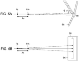
- Figs. 5A and 5B schematically show the astigmatism of parallel beams incident on a partial region 98 on a concavely curved surface 96 and show views from different points of view.
- Fig. 5A shows light beams within the meridional plane (yz plane) of the concavely curved surface 96
- Fig. 5B shows light beams within the sagittal plane (xz plane) of the concavely curved surface 96.
- the points of convergence Fm and Fs of the parallel beams differ between the meridional plane and the sagittal plane.
- the focal point Fs within the sagittal plane is located farther from the concavely curved surface 96 than the focal point Fm within the meridional plane.
- the focal distance of the concave mirror Denoting the focal distance of the concave mirror by f and the angle of incidence and reflection of light on the concave mirror by ⁇ , the focal distance of diagonally incident light is given by f ⁇ cos ⁇ .
- the focal distance within the meridional plane on which the light beam is diagonally incident will be shortened to f ⁇ cos ⁇ . Meanwhile, the focal distance within the sagittal plane will be enlarged to f/cos ⁇ .
- the angle of incidence and reflection ⁇ on the concavely curved surface 96 may be reduced.
- This is addressed in this embodiment by configuring the projection optical system 14 to reduce the astigmatism in the composite optical system formed by the virtual image presentation plate 22 and the projection optical system 14 as a whole. More specifically, mitigation of the occurrence of double images and reduction of the astigmatism in the composite optical system are both achieved by using one or more of the features listed in (1)-(5) below.
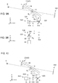
- Figs. 6A-6C show a configuration of the virtual image display device 10 according to the first embodiment in detail and show views from different points of view.
- Fig. 6A corresponds to Fig. 1 and shows a configuration viewed on the yz plane.
- Fig. 6B shows a configuration viewed on the xz plane, and
- Fig. 6C shows a configuration viewed on the xy plane.
- the embodiment uses the feature (1) above, the concave mirror 16 included in the projection optical system 14 is arranged at a position twisted with respect to the virtual image presentation plate 22.
- the virtual image display device 10 includes an illumination unit 11, a display unit 12, and a projection optical system 14.
- the projection optical system 14 includes a concave mirror 16 and a convex lens 18.
- the illumination unit 11, the display unit 12, the convex lens 18, and the concave mirror 16 are arranged on the light axis extending in the x direction.
- the concave mirror 16 reflects, toward the virtual image presentation plate 22 and in the y direction, the image display light L incident in the x direction.
- the virtual image presentation plate 22 reflects, toward the user E and in the z direction, the image display light L incident in the y direction.
- the virtual image presentation plate 22 is configured such that the first surface 23 is concavely curved.
- the first surface 23 of the virtual image presentation plate 22 is a first concavely curved surface on which the image display light L is incident and reflected diagonally.
- the virtual image presentation plate 22 is configured to have a uniform thickness t, and the curved surfaces of the first surface 23 and the second surface 24 are identically shaped.
- the virtual image presentation plate 22 is arranged such that the direction (axis A) orthogonal to both the direction of incidence and the direction of reflection of the image display light L on the first surface 23 (first concavely curved surface) is the x direction.
- the concave mirror 16 is a projection mirror that projects the image display light L toward the virtual image presentation plate 22.
- the convex lens 18 is provided between the display unit 12 and the concave mirror 16.
- the concave mirror 16 has a second concavely curved surface on which the image display light L is incident and reflected diagonally and is arranged such that the direction (axis B) orthogonal to both the direction of incidence and the direction of reflection of the image display light L on the second concavely curved surface is the z direction. Therefore, the orientation of the axis B of the concave mirror 16 is orthogonal to the orientation of the axis A of the virtual image presentation plate 22, and the concave mirror 16 and the virtual image presentation plate 22 are in a twisted arrangement.
- the virtual image presentation plate 22 and the concave mirror 16 are in a twisted arrangement so that the astigmatism produced in the virtual image presentation plate 22 and the astigmatism produced in the concave mirror 16 occur in the opposite directions.
- the parallel beams are incident on the meridional plane (yz plane) of the virtual image presentation plate 22
- the parallel beams are reflected by the virtual image presentation plate 22 and the concave mirror 16 and are transmitted through the convex lens 18, before being converged on the light axis of the display unit 12 in the x direction within the xz plane.
- the virtual image presentation plate 22 operates, on the light axis of the display unit 12, to shorten the focal distance of the light beam within the xz plane and enlarge the focal distance of the light beam within the xy plane.
- the concave mirror 16 operates to shorten the focal distance of the light beam within the xy plane and shorten the focal distance of the light beam within the xz plane. Therefore, by combining the virtual image presentation plate 22 and the concave mirror 16 in a twisted arrangement like this, the astigmatism is reduced as compared with a case where the concave mirror 16 in a twisted arrangement is not provided.
- the concave mirror 16 and the virtual image presentation plate 22 For reduction of the astigmatism in the composite optical system 20 in which the concave mirror 16 and the virtual image presentation plate 22 are combined, it will be necessary to ensure that the astigmatism in the concave mirror 16 and that of the virtual image presentation plate 22 are substantially equal. More specifically, this requires ensuring that the product f a .cos ⁇ a of the focal distance fa of the concave mirror 16 and the cosine cos ⁇ a of the angle of incidence and reflection of the image display light L on the concave mirror 16 is substantially equal to the product f b ⁇ cos ⁇ b of the focal distance fb of the virtual image presentation plate 22 and the cosine cos ⁇ b of the angle of incidence and reflection of the image display light L on the virtual image presentation plate 22.
- the focal distance f a ⁇ cos ⁇ a of the concave mirror 16 within the meridional pane is not less than 0.5 times and not more than twice the focal distance f b ⁇ cos ⁇ b of the virtual image presentation plate 22 within the meridional plane.
- the display unit 12 at the focal point within the meridional plane of the composite optical system 20 formed by the convex lens 18 and the virtual image presentation plate 22, the occurrence of double images caused by the virtual image presentation plate 22 having the two surfaces 23 and 24 is eliminated.
- the focal point of the composite optical system 20 within the meridional plane is the position of convergence of parallel beams assumed to be incident from the user E toward the virtual image presentation plate 22 along the meridional plane (yz plane) of the virtual image presentation plate 22.
- the occurrence of double images is mitigated without using a virtual presentation image of a customized specification such as a wedge glass, by providing the display unit 12 at the focal point of the composite optical system 20 within the meridional plane. Further, by providing the concave mirror 16 in a twisted arrangement with respect to the virtual image presentation plate 22, the astigmatism in the composite optical system 20 is reduced and reduction of the imaging performance caused by astigmatism is prevented. This can enhance the visibility of the virtual image 50 presented to the user E.
- Fig. 7 shows a configuration of a virtual image display device 110 according to the second embodiment in detail.
- This embodiment differs from the first embodiment in that the axis A of the virtual image presentation plate 22 and the axis B of a concave mirror 116 are aligned in the same direction (x direction), and the concave mirror 116 is not in a twisted arrangement with respect to the virtual image presentation plate 22.
- the virtual image display device 110 includes an illumination unit 11, a display unit 12, and a projection optical system 114.
- the projection optical system 114 includes a concave mirror 116 and a convex lens 18.
- the concave mirror 116 is a projection mirror having a concavely curved surface on which the image display light L is incident and reflected diagonally.
- the illumination unit 11, the display unit 12, the convex lens 18, and the concave mirror 116 are arranged on the light axis extending in the z direction.
- the concave mirror 116 reflects the image display light L incident in the z direction toward the virtual image presentation plate 22.
- the virtual image presentation plate 22 reflects the image display light L from the concave mirror 116 toward the user E.
- the concave mirror 116 is configured such that the curvature within the meridional plane (first cross section) and the curvature within the sagittal plane (second cross section) are different in order to reduce the astigmatism in the composite optical system 120 formed by the projection optical system 114 and the virtual image presentation plate 22.
- the meridional plane of the concave mirror 116 is a plane (yz plane) that includes both the direction of incidence and the direction of reflection of the image display light diagonally incident on the concave mirror 116 and that intersects the concavely curved surface of the concave mirror 116.
- the sagittal plane of the concave mirror 116 is a plane orthogonal to the meridional plane and is a plane that is along the direction (x direction) orthogonal to both the direction of incidence and the direction of reflection of the image display light and that intersects the concavely curved surface of the concave mirror 116.
- the curvature within the meridional plane is related to the focal distance of parallel beams incident along the meridional plane, i.e., related to the focal distance within the meridional plane.
- the curvature within the sagittal plane is related to the focal distance within the sagittal plane.
- the focal point of the composite optical system 120 within the meridional plane and the focal point within the sagittal plane are made to coincide by appropriately setting the curvature of the concave mirror 116 within the meridional plane and the curvature within the sagittal plane.
- the difference between the focal distance within the meridional plane and the focal distance within the sagittal plane is reduced by configuring the curvature of the concave mirror 116 within the meridional plane to be smaller than the curvature within the sagittal plane.
- the specific curvature of the concave mirror 116 in accordance with the curvature of the virtual image presentation plate 22 within the meridional plane and the curvature thereof within the sagittal plane, the angle of incidence and reflection ⁇ a of the image display light L on the virtual image presentation plate 22, and the angle of incidence and reflection ⁇ b of the image display light L on the concave mirror 116.
- the astigmatism in the composite optical system 120 is reduced and reduction of the imaging performance caused by astigmatism is prevented by configuring the curvature of the concave mirror 116 within the meridional plane and the curvature thereof within the sagittal plane to be different. Further, the occurrence of double images is inhibited by providing the display unit 12 at the focal point of the composite optical system 120 within the meridional plane. In this way, a highly visible virtual image 150 is presented to the user.
- this embodiment is applicable to a case where the first surface 23 of the virtual image presentation plate 22 is a flat surface. In this case, the astigmatism in the virtual image presentation plate 22 is negligible. It therefore suffices to set the curvature of the concave mirror 116 within the meridional plane and the curvature thereof within the sagittal plane to have different values so as to reduce the astigmatism in the concave mirror 116.
- Fig. 8 shows a configuration of a virtual image display device 210 according to the third embodiment in detail. This embodiment differs from the foregoing embodiments in that a plane parallel plate 219 provided at an angle between the display unit 12 and a convex lens 218 is added.
- the virtual image display device 210 includes an illumination unit 11, a display unit 12, and a projection optical system 214.
- the projection optical system 214 includes a concave mirror 216, a convex lens 218, and the plane parallel plate 219.
- the illumination unit 11, the display unit 12, the plane parallel plate 2149, the convex lens 218, and the concave mirror 216 are arranged on the light axis extending in the z direction.
- the plane parallel plate 219 is a transparent member having a uniform thickness and is made of glass or a resin material.
- the plane parallel plate 219 is provided at an angle to the light path of the projection optical system 214 such that the rotational axis C is aligned with the direction (x direction) orthogonal to the meridional plate (yz plane). Inserting the plane parallel plate 219 at an angle enlarges the focal distance of a composite optical system 220 formed by the virtual image presentation plate 22 and the projection optical system 214.
- configuring the direction of the rotational axis C of the plane parallel plate 219 to be orthogonal to the meridional plane enlarges the focal distance within the meridional plane as compared with the focal distance within the sagittal plane.
- the amount by which the focal distance increases by providing the plane parallel plate 219 depends on the angle of inclination ⁇ c of the plane parallel plate 2219 so that the astigmatism can be adjusted by changing the angle of inclination ⁇ c .
- the astigmatism in the composite optical system 220 is reduced by inserting the plane parallel plate 219. Further, the occurrence of double images is inhibited by providing the display unit 12 at the focal point of the composite optical system 220 within the meridional plane. This can enhance the visibility of a virtual image 250.
- Figs. 9A and 9B show a configuration of a virtual image display device 310 according to the fourth embodiment in detail and show views from different points of view.
- Fig. 9A corresponds to Fig. 1 and shows a configuration viewed on the yz plane
- Fig. 9B shows a configuration viewed on the xz plane.
- the projection optical system 314 includes two concave mirrors 316 and 318, and the two concave mirrors 316 and 318 are in a twisted arrangement.
- the virtual image display device 310 includes an illumination unit 11, a display unit 12, and a projection optical system 314.
- the projection optical system 314 includes a first concave mirror 316 and a second concave mirror 318.
- the illumination unit 11, the display unit 12, and the second concave mirror 318 are arranged on the light axis extending in the x direction.
- the second concave mirror 318 is arranged such that the direction (axis D) orthogonal to both the direction of incidence and the direction of reflection of the image display light L is the y direction and reflects, in the z direction, the image display light L incident in the x direction.
- the first concave mirror 316 is arranged such that the direction (axis B) orthogonal to both the direction of incidence and the direction of reflection of the image display light L is the x direction and reflects the image display light L incident in the z direction toward the virtual image presentation plate 22.
- the astigmatism produced in the respective concave mirrors is made to occur in the opposite directions.
- the mechanism to mitigate the astigmatism by combining two concavely curved surfaces is as described in the first embodiment. Therefore, this embodiment can also reduce the astigmatism in the composite optical system 320 formed by the virtual image presentation plate 22 and the projection optical system 314 and enhance the imaging performance. Further, the occurrence of double images is inhibited by providing the display unit 12 at the focal point of the composite optical system 320 within the meridional plane. This can enhance the visibility of the virtual image 350.
- this embodiment is applicable to a case where the first surface 23 of the virtual image presentation plate 22 is a flat surface. In this case, the astigmatism in the virtual image presentation plate 22 is negligible. It therefore suffices to set the curvature and the angles of incidence and reflection ⁇ b , ⁇ d of the two concave mirrors 316, 318 respectively so as to reduce the astigmatism in the combination of the first concave mirror 316 and the second concave mirror 318.
- the projection optical system 314 is not provided with a convex lens, but an additional convex lens may be provided in the projection optical system 314.
- an additional convex lens may be provided between the display unit 12 and the second concave mirror 318, or an additional convex lens may be provided between the second concave mirror 318 and the first concave mirror 316.
- Fig. 10 shows a configuration of a virtual image display device 410 according to the fifth embodiment in detail.
- This embodiment differs from the foregoing embodiments in that a convex mirror 416 is used to mitigate the astigmatism produced in the virtual image presentation plate 22.
- the concavo-convex shapes of the virtual image presentation plate 22 and the projection mirror are reversed to produce the astigmatism in the respective curved surfaces in the opposite directions, thereby reducing the astigmatism in the composite optical system as a whole.
- the virtual image display device 410 includes an illumination unit 11, a display unit 12, and a projection optical system 414.
- the projection optical system 414 includes a convex mirror 416 and a convex lens 418.
- the illumination unit 11, the display unit 12, the convex lens 418, and the convex mirror 416 are arranged on the light axis extending in the z direction.
- the convex mirror 416 is a projection mirror having a convexly curved surface of incidence and reflection of the image display light L.
- the convex mirror 416 is arranged such that the direction (axis B) orthogonal to both the direction of incidence and the direction of reflection of the image display light L is the x direction and reflects the image display light L incident in the z direction toward the virtual image presentation plate 22.
- the virtual image presentation plate 22 is configured such that the first surface 23, on which the image display light L is incident, is concavely curved and is arranged such that the direction (axis A) orthogonal to both the direction of incidence and the direction of reflection of the image display light L is the x direction.
- the virtual image presentation plate 22 reflects the image display light L from the convex mirror 416 toward the user E.
- the virtual image presentation plate 22 and the convex mirror 416 are arranged to face each other such that the respective curved surfaces have the opposite concavo-convex shapes. Therefore, the astigmatism produced in the respective curved surfaces is reduced or canceled. This reduces the astigmatism in a composite optical system 420 formed by the virtual image presentation plate 22 and the projection optical system 414 and enhances the imaging performance. Further, the occurrence of double images is inhibited by providing the display unit 12 at the focal point of the composite optical system 420 within the meridional plane. Thus, according to this embodiment, astigmatism and doubles images are both reduced, and the visibility of a virtual image 450 presented to the user E is enhanced.
- the embodiment described above shows that the astigmatism in the composite optical system is mitigated by using one of the features (1)-(5) described above.
- a plurality of features may be combined.
- the feature (2) or the feature (3) may be combined with the feature (1)
- the feature (3) or the feature (4) may be combined with the feature (2)
- the feature (4) or the feature (5) may be combined with the feature (3).
- the first surface 23 of the virtual image presentation plate 22 is formed by a concavely curved surface or a flat surface.
- the composite optical system may be configured to mitigate the astigmatism of the convexly curved first surface 23 of the virtual image presentation plate 22.
- the concave mirror 16 may be replaced by a convex mirror.
- curvature within the meridional plane may be larger than the curvature within the sagittal plane.
- the convex mirror 416 may be replaced by a concave mirror.
- a convex lens is included in the projection optical system.
- a convex lens may not be provided in the projection optical system.
- the convex lens 18 may not be included in the projection optical system 14, and the display unit 12 may be provided at the focal point within the meridional plane of the composite optical system 20 not including the convex lens 18.
- the convex lens 18 may not be included in the projection optical system 114 of the embodiment shown in Fig. 7
- the convex lens 218 may not be included in the projection optical system 214 of the embodiment shown in Fig. 8 .
- a virtual image display device for presenting a virtual image to a user via a virtual image presentation plate, comprising:
- the projection mirror is configured such that a curvature in a second cross section intersecting the second concavely curved surface is larger than a curvature in a first cross section intersecting the second concavely curved surface
- the first cross section is a plane that includes both the direction of incidence and the direction of reflection of the image display light incident on the second concavely curved surface diagonally
- the second cross section is a plane orthogonal to the first cross section and is a plane along a direction orthogonal to both the direction of incidence and the direction of reflection of the image display light incident on the second concavely curved surface diagonally.
- the virtual image display device according to item 1-1 or item 1-2, wherein the projection optical system further includes a plane parallel plate provided at an angle to a light path of the projection optical system.
- a virtual image display device for presenting a virtual image to a user via a virtual image presentation plate, comprising:
- the projection optical system further includes a plane parallel plate provided at an angle to a light path of the projection optical system.
- a virtual image display device for presenting a virtual image to a user via a virtual image presentation plate, comprising:
- a virtual image display device for presenting a virtual image to a user via a virtual image presentation plate, comprising:
- a curved surface of at least one of the first concave mirror and the second concave mirror is configured such that a curvature in a second cross section intersecting the curved surface is larger than a curvature in a first cross section intersecting the curved surface
- the first cross section is a plane that includes both the direction of incidence and the direction of reflection of the image display light incident on the curved surface diagonally
- the second cross section is a plane orthogonal to the first cross section and is a plane along a direction orthogonal to both the direction of incidence and the direction of reflection of the image display light incident on the curved surface diagonally.
- the projection optical system further includes a plane parallel plate provided at an angle to a light path of the projection optical system.
- a virtual image display device for presenting a virtual image to a user via a virtual image presentation plate, comprising:
- the projection optical system further includes a plane parallel plate provided at an angle to a light path of the projection optical system.
- a lens may be used as an optical device of transmission type provided at an angle to the light path of the projection optical system.
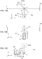
- Fig. 11 shows a configuration of a virtual image display device 510 according to the sixth embodiment in detail.
- the virtual image display device 510 includes an illumination unit 11, a display unit 12, and a projection optical system 14.
- the projection optical system 514 includes a concave mirror 16 and a convex lens 36.
- the illumination unit 11, the display unit 12, the convex lens 36, and the concave mirror 16 are arranged on the light axis extending in the z direction.
- the convex lens 36 is provided such that the light axis of the convex lens 36 intersects at an angle to the light path extending in the z direction.
- the concave mirror 16 reflects, toward the virtual image presentation plate 22 and in the y direction, the image display light L incident in the z direction.
- the virtual image presentation plate 22 reflects, toward the user E and in the z direction the image display light L incident in the y direction.
- the virtual image display device 510 includes a display light generation unit 30.
- the display light generation unit 30 is a module component in which the illumination unit 11, the display unit 12, and the convex lens 36 are integrated.
- the display light generation unit 30 has a housing 32, and the illumination unit 11 and the display unit 12 are housed in the housing 32.
- the convex lens 36 is fitted to the housing 32 to block an output port 34 of the housing 32 through which the image display light L is output.
- the convex lens 36 has a function of a duct control cover that seals the interior of the housing 32 and prevents invasion of dirt and dust into the housing 32. In the illustrated example, the convex lens 36 is fitted such that the convex lens 36 is in direct contact with the output port 34 of the housing 32.
- the convex lens 36 may be fitted to the output port 34 via a fixing member fitted to the outer circumference of the convex lens 36.
- a sealing member such as an O ring for improving the sealing capability may be provided between the output port 34 and the convex lens 36.
- the virtual image presentation plate 22 is configured such that the first surface 23 on which the image display light L is incident and reflected diagonally is concavely curved surface.
- the virtual image presentation plate 22 is configured to have a uniform thickness t, and the curved surfaces of the first surface 23 and the second surface 24 are identically shaped.
- the virtual image presentation plate 22 is provided such that the direction (axis A) orthogonal to both the direction of incidence and the direction of reflection of the image display light L on the first surface 23 is the x direction.
- the angle of incidence and reflection of the image display light on the virtual image presentation plate 22 is ⁇ a
- the focal distance of the concavely curved surface of the virtual image presentation plate 22 is f a .
- the concave mirror 16 is a projection mirror that projects the image display light L toward the virtual image presentation plate 22.
- the concave mirror 16 has a concavely curved surface on which the image display light L is incident and reflected diagonally and is arranged such that the direction (axis B) orthogonal to both the direction of incidence and the direction of reflection of the image display light L on the concavely curved surface is the x direction. Therefore, the orientation of the axis B of the concave mirror 16 is parallel to the orientation of the axis A of the virtual image presentation plate 22, and the concave mirror 16 and the virtual image presentation plate 22 are provided to face each other.
- the angle of incidence and reflection of the image display light on the concave mirror 16 is ⁇ b
- the focal distance of the concavely curved surface of the concave mirror 16 is f b .
- the convex lens 36 is provided between the display unit 12 and the concave mirror 16.
- the convex lens 36 is provided at an angle to the light path of the projection optical system 514 such that the rotational axis C is aligned with the direction (x direction) orthogonal to the meridional plate (yz plane).
- the curved surface of the convex lens 36 through which the image display light L is transmitted is shaped in rotational symmetry around the light axis of the lens.
- the convex lens 36 is comprised of a spherical surface.
- Providing the convex lens 36 at an angle and configuring the direction of the rotational axis C of the convex lens 36 to be orthogonal to the meridional plane makes the focal distance of the projection optical system 514 within the meridional plane larger than the focal distance within the sagittal plane. This reduces the difference between the focal distance of a composite optical system 520 within the meridional plane and the focal distance within the sagittal plane as compared with the case of not providing the convex lens 36 at an angle and mitigates the astigmatism in the composite optical system 520 as a whole.
- the amount by which the focal distance is adjusted by providing the convex lens 36 at an angle is dependent on the angle of inclination ⁇ c of the convex lens 36 and the focal distance f c of the convex lens 36. For this reason, the astigmatism in the composite optical system 520 can be adjusted by changing the angle of inclination ⁇ c and the focal distance f c of the convex lens 36.
- the astigmatism of an optical device is proportional to the product f ⁇ cos ⁇ of the focal distance f of the optical device and the cosine cos ⁇ of the angle of inclination ⁇ of the optical device with respect to the light path. Further, the astigmatism is produced in the opposite directions in the convex lens 36 and in the concave mirror 16/the virtual image presentation plate 22.
- the astigmatism in the composite optical system 520 as a whole can be reduced by balancing the astigmatism (f c ⁇ cos ⁇ c ) of the convex lens 36, the astigmatism (f b ⁇ cos ⁇ b ) of the concave mirror 16, and the astigmatism (f a ⁇ cos ⁇ a ) of the virtual image presentation plate 22. This can suitably prevent reduction of the imaging performance caused by the astigmatism.
- the display unit 12 at the focal point within the meridional plane of the composite optical system 520 formed by the concave mirror 16 and the virtual image presentation plate 22, the occurrence of double images caused by the virtual image presentation plate 22 having the two surfaces 23, 24 is eliminated.
- the focal point of the composite optical system 20 within the meridional plane is the position of convergence of parallel beams assumed to be incident from the user E toward the virtual image presentation plate 22 along the meridional plane (yz plane) of the virtual image presentation plate 22.
- the occurrence of double images is mitigated without using a virtual presentation image of a customized specification such as a wedge glass, by providing the display unit 12 at the focal point of the composite optical system 520 within the meridional plane. Further, by providing the concave mirror 36 at an angle, the astigmatism in the composite optical system 520 is reduced and reduction of the imaging performance caused by astigmatism is prevented. This can enhance the visibility of a virtual image 550 presented to the user E.
- the astigmatism can be reduced by using an ordinary, inexpensive lens such as a spherical lens instead of a special expensive aspherical lens, etc. for mitigating astigmatism. Therefore, the manufacturing cost is reduced.
- the embodiment is also applicable to a case where the virtual image presentation plate 22 is comprised of a flat surface.
- the astigmatism is not produced in the virtual image presentation plate 22 so that the astigmatism in the composite optical system 520 as a whole is reduced by configuring the astigmatism (f b ⁇ cos ⁇ b ) produced in the concave mirror 16 to be similar to the astigmatism (f c ⁇ cos ⁇ c ) produced in the convex lens 36.
- Fig. 12 shows a configuration of a virtual image display device 610 according to the seventh embodiment in detail.
- This embodiment differs from the foregoing embodiments in that a further convex lens (also referred to as a second convex lens) 618 is inserted between the concave mirror 16 and a convex lens (also referred to as a first convex lens) 36 provided at an angle.
- a further convex lens also referred to as a second convex lens
- a convex lens also referred to as a first convex lens
- the virtual image display device 610 includes an illumination unit 11, a display unit 12, and a projection optical system 614.
- the virtual image display device 610 includes a display light generation unit 30, and the display light generation unit 30 includes the illumination unit 11, the display unit 12, the housing 32, and the first convex lens 36.
- the projection optical system 614 includes the first convex lens 36, the second convex lens 618, and the concave mirror 16.
- the composite optical system 620 is comprised of the virtual image presentation plate 22 and the projection optical system 614.
- the first convex lens 36 is provided at an angle to the light path of the projection optical system 614.
- the second convex lens 618 is provided such that the light path of the projection optical system 614 and the light axis of the lens are parallel.
- the curved surface of the first convex lens 36 and the second convex lens 618 through which the image display light L is transmitted is shaped in rotational symmetry around the light axis of the lens.
- the convex lens 36 and the second concave lens 618 are comprised of a spherical surface.
- the astigmatism in the composite optical system 620 and the imaging performance can both be suitably adjusted by combining the first convex lens 36 provided at an angle to the light path and the second convex lens 618 provided perpendicular to the light path.
- the focal distance fc and the angle of inclination ⁇ c of the first convex lens 36 may be selected to reduce the astigmatism in the composite optical system 620, and the focal distance and arrangement of the second convex lens 618 may be determined to improve the imaging performance of the composite optical system 620.
- the visibility of the virtual image 650 presented to the user E is enhanced according to the embodiment.
- Figs. 12A-12C show a configuration of the virtual image display device according to the eighth embodiment in detail.
- Fig. 12A corresponds to Fig. 11 and shows a configuration viewed on the yz plane.
- Fig. 12B shows a configuration viewed on the xz plane, and
- Fig. 12C shows a configuration viewed on the xy plane.
- This embodiment differs from the sixth embodiment in that the virtual image presentation plate 22 and the concave mirror 16 are in a twisted arrangement.
- the virtual image display device 710 includes an illumination unit 11, a display unit 12, and a projection optical system 714.
- the virtual image display device 710 includes a display light generation unit 30, and the display light generation unit 30 includes the illumination unit 11, the display unit 12, the housing 32, and the convex lens 36.
- the projection optical system 714 includes the concave mirror 16 and the convex lens 36.
- the illumination unit 11, the display unit 12, the convex lens 36, and the concave mirror 16 are arranged on the light axis extending in the x direction.
- the concave mirror 16 reflects, toward the virtual image presentation plate 22 and in the y direction, the image display light L incident in the x direction.
- the virtual image presentation plate 22 reflects, toward the user E and in the z direction, the image display light L incident in the y direction.
- the virtual image presentation plate 22 is configured such that the first surface 23 on which the image display light L is incident and reflected diagonally is a concavely curved surface.
- the virtual image presentation plate 22 is arranged such that the direction (axis A) orthogonal to both the direction of incidence and the direction of reflection of the image display light L on the first surface 23 is the x direction.
- the concave mirror 16 is arranged such that the direction (axis B) orthogonal to both the direction of incidence and the direction of reflection of the image display light L is the z direction. Therefore, the orientation of the axis B of the concave mirror 16 is orthogonal to the orientation of the axis A of the virtual image presentation plate 22, and the concave mirror 16 and the virtual image presentation plate 22 are in a twisted arrangement.
- the virtual image presentation plate 22 and the concave mirror 16 are in a twisted arrangement so that the astigmatism produced in the virtual image presentation plate 22 and the astigmatism produced in the concave mirror 16 occur in the opposite directions.
- the parallel beams are incident on the meridional plane (yz plane) of the virtual image presentation plate 22
- the parallel beams are reflected by the virtual image presentation plate 22 and the concave mirror 16 and are transmitted through the convex lens 36, before being converged on the light axis of the display unit 12 in the x direction within the xz plane.
- the virtual image presentation plate 22 operates, on the light axis of the display unit 12, to shorten the focal distance of the light beam within the xz plane and enlarge the focal distance of the light beam within the xy plane.
- the concave mirror 16 operates to shorten the focal distance of the light beam within the xy plane and shorten the focal distance of the light beam within the xz plane. Therefore, by combining the virtual image presentation plate 22 and the concave mirror 16 in a twisted arrangement like this, the astigmatism is reduced as compared with a case where the concave mirror 16 in a twisted arrangement is not provided.
- the convex lens 36 is provided between the display unit 12 and the concave mirror 16 and is provided at an angle to the light path extending in the x axis direction.
- the convex lens 36 is provided such that the rotational axis C is aligned with the direction (z direction) orthogonal to the meridional plate (xy plane) of the concave mirror 16.
- the astigmatism in a composite optical system 720 is reduced by providing the concave mirror 16 in a twisted arrangement with respect to the virtual image presentation plate 22. Further, the astigmatism in the composite optical system 720 is further reduced by providing the convex lens 36 of the display light generation unit 30 at an angle. This can prevent reduction of the imaging performance caused by astigmatism and enhance the visibility of a virtual image 750 presented to the user E.
- the direction of rotation of the convex lens 36 may be changed. More specifically, the astigmatism produced by the virtual image presentation plate 22 is reduced by the convex lens 36 by providing the convex lens 36 at an angle such that the rotational axis C of the convex lens 36 is aligned with the y direction.
- a concave lens may be used instead pf the convex lens 36.
- the astigmatism produced by the virtual image presentation plate 22 is reduced by the convex lens by providing the concave lens at an angle such that the rotational axis C of the concave lens is aligned with the z direction.
- the curvature of the concave mirror 16 (projection mirror) within the meridional plane (first cross section) may be different from the curvature within the sagittal plane (second cross section).
- the meridional plane of the concave mirror 16 is a plane that includes both the direction of incidence and the direction of reflection of the image display light diagonally incident on the concave mirror 16 and that intersects the concavely curved surface of the concave mirror 16.
- the sagittal plane of the concave mirror 16 is a plane orthogonal to the meridional plane and is a plane that is along the direction orthogonal to both the direction of incidence and the direction of reflection of the image display light and that intersects the concavely curved surface of the concave mirror 116.
- the curvature within the meridional plane is related to the focal distance of parallel beams incident along the meridional plane, i.e., related to the focal distance within the meridional plane.
- the curvature within the sagittal plane is related to the focal distance within the sagittal plane. It is therefore ensured that the focal point of the composite optical system 120 within the meridional plane and the focal point within the sagittal plane are made to coincide by appropriately setting the curvature of the concave mirror 16 within the meridional plane and the curvature within the sagittal plane.
- the difference between the focal distance within the meridional plane and the focal distance within the sagittal plane is reduced by configuring the curvature of the concave mirror 16 within the meridional plane to be smaller than the curvature within the sagittal plane.
- the astigmatism in the composite optical system is reduced and reduction of the imaging performance caused by astigmatism is prevented.
- the first surface 23 of the virtual image presentation plate 22 is formed by a concavely curved surface or a flat surface.
- the composite optical system may be configured to mitigate the astigmatism of the convexly curved first surface 23 of the virtual image presentation plate 22.
- the concave mirror projection mirror
- the convex lens 36 of the display light generation unit 30 may be replaced by a concave lens.
- the illumination unit 11, the display unit 12, and the convex lens 36 are integrated as the display light generation unit 30. In one variation, these components may not be configured as an integrated module.
- the convex lens 36 provided in the display light generation unit 30 may be replaced by a plane parallel plate.
- E user, L ... image display light, 10 ... virtual image display device, 12 ... display unit, 14 ... projection optical system, 16 ... concave mirror (projection mirror), 20 ... composite optical system, 22 ... virtual image presentation plate, 50, 62 ... windshield
- the occurrence of double images is reduced and the visibility of the virtual image is improved.
Landscapes
- Physics & Mathematics (AREA)
- Engineering & Computer Science (AREA)
- General Physics & Mathematics (AREA)
- Optics & Photonics (AREA)
- Multimedia (AREA)
- Signal Processing (AREA)
- Chemical & Material Sciences (AREA)
- Combustion & Propulsion (AREA)
- Transportation (AREA)
- Mechanical Engineering (AREA)
- Instrument Panels (AREA)
Abstract
Description
- The present invention relates to a virtual image display device.
- Recently, head-up displays are available for use as display devices for vehicles. A head-up display projects an image display light toward, for example, a windshield of a vehicle, superimposes a virtual image based on the image display light on the scenery outside the vehicle, and displays the resultant image. A windshield has two interfaces inside and outside the vehicle. The image display lights reflected at the respective interfaces and visually perceived may be superimposed with a shift and viewed as double images. To inhibit double images from being produced, there is proposed a mathematical expression for defining a viewing distance to contain the amount of shift between double images within the resolution of the human eyes and obtaining an optical arrangement that realizes the viewing distance (see, for example, patent document 1).
- [patent document 1]
JP62-225429 - The technology described above requires a large viewing distance to the position of presentation of a virtual image ahead of the user in order to reduce double images. It is preferred to reduce the occurrence of double images suitably, regardless of the viewing distance to a virtual image.
- The embodiments address the above-described issue, and a general purpose thereof is to provide a technology for improving the visibility of a virtual image presented.
- An embodiment of the present invention relates to a virtual image display device for presenting a virtual image to a user via a virtual image presentation plate, including: a display unit that generates an image display light; and a projection optical system that projects the image display light toward the virtual image presentation plate. The projection optical system includes a projection mirror that projects the image display light toward the virtual image presentation plate and an optical device of transmission type provided such that a light axis of the optical device intersects at an angle to a light path of the projection optical system. The display unit is provided at a focal point of a composite optical system within a meridional plane, the composite optical system being formed by the virtual image presentation plate and the projection optical system, and the focal point of the composite optical system within the meridional plane is a position of convergence of parallel beams assumed to be incident from the user toward the virtual image presentation plate along the meridional plane of the virtual image presentation plate.
- Optional combinations of the aforementioned constituting elements, and mutual substitution of constituting elements and implementations of the present invention between methods, apparatuses, and systems may also be practiced as additional modes of the present invention.
- According to the invention, the occurrence of double images is reduced and the visibility of the virtual image is improved.
-
-
Fig. 1 schematically shows a configuration of a virtual image display device according to the embodiment; -
Fig. 2 schematically shows the occurrence of double images induced by the virtual image presentation plate; -
Fig. 3 schematically shows inhibition of double images effected by a wedge glass; -
Fig. 4 shows an optical arrangement in a virtual image display device according to the comparative embodiment in detail; -
Figs. 5A and 5B schematically show the astigmatism of parallel beams incident on a partial region on a concavely curved surface; -
Figs. 6A-6C show a configuration of the virtual image display device according to the first embodiment in detail; -
Fig. 7 shows a configuration of a virtual image display device according to the second embodiment in detail; -
Fig. 8 shows a configuration of a virtual image display device according to the third embodiment in detail; -
Figs. 9A and 9B show a configuration of a virtual image display device according to the fourth embodiment in detail; -
Fig. 10 shows a configuration of a virtual image display device according to the fifth embodiment in detail; -
Fig. 11 shows a configuration of a virtual image display device according to the sixth embodiment in detail; -
Fig. 12 shows a configuration of a virtual image display device according to the seventh embodiment in detail; and -
Fig. 13 shows a configuration of a virtual image display device according to the eighth embodiment in detail. - A description will be given of embodiments of the present invention with reference to the drawings. Specific numerical values are shown in the embodiments by way of example only to facilitate the understanding of the invention and should not be construed as limiting the scope of the invention unless specifically indicated as such. Those elements in the specification and drawings that have substantially the identical function and configuration are represented by the same reference symbols, and the description is not duplicated. Elements not directly relevant to the invention are omitted from the illustration.
-
Fig. 1 schematically shows a configuration of a virtualimage display device 10 according to the embodiment. In this embodiment, the virtualimage display device 10 is installed in a dashboard of avehicle 60, which exemplifies a moving object. The virtualimage display device 10 is a so-called head-up display device. The virtualimage display device 10 presents avirtual image 50 in front of thevehicle 60 in the direction of travel (rightward direction inFig. 1 ) by projecting an image display light toward awindshield 62, which is a virtual image presentation plate. The user E (e.g., the driver) can see thevirtual image 50 superimposed on the actual scenery via thewindshield 62. Therefore, the driver E can access information shown in thevirtual image 50 substantially without moving the line of sight while driving the vehicle. Referring to theFig. 1 , the direction of travel of the vehicle 60 (longitudinal direction) is defined as the z direction, the vertical direction of the vehicle 60 (up/down direction) is defined as the y direction, and the transversal direction of thevehicle 60 is defined as the x direction. - The virtual
image display device 10 includes anillumination unit 11, adisplay unit 12, a projectionoptical system 14, and acontrol unit 40. Theillumination unit 11 is a light source for generating a display light and generates an illumination light for illuminating thedisplay unit 12. Theillumination unit 11 includes a light emitting device such as a light emitting diode (LED) and a laser diode (LD), and an optical device for adjusting the light intensity distribution and angle distribution of the light output from the light emitting device. Theillumination unit 11 provides thedisplay unit 12 with a substantially uniform white light. The configuration of theillumination unit 11 is not limited to any particular type. For example, a light emitting device such as a light tunnel, a Fresnel lens, and a light diffusion plate may be used to condition the output light from the light emitting device. - The
display unit 12 modulates an illumination light from theillumination unit 11 to generate a display light and forms an intermediate image (real image) corresponding to the display content of thevirtual image 50. Thedisplay unit 12 includes an image display device of transmission type for generating a display light. For example, thedisplay unit 12 includes a display device such as a liquid crystal panel of transmission type. The image display device receives an image signal transmitted from thecontrol unit 40 and generates an image display light for the display content corresponding to the image signal. Thedisplay unit 12 may further include an optical device for conditioning the orientation and light distribution angle of the image display light. Further, thedisplay unit 12 may be configured by combining an element other than a liquid crystal panel of transmission type and a screen of transmission type such as a microlens array sheet and a light diffusion sheet. The element is exemplified by a projection unit such as a digital micromirror device (DMD), a liquid crystal on silicon (LOCS) laser scanning module (LSM), and a micro electro mechanical system (MEMS) LSM. - The projection
optical system 14 projects the image display light generated by thedisplay unit 12 toward thewindshield 62. The projectionoptical system 14 includes an optical device of transmission type such as a convex lens and an optical device of reflection type such as a concave mirror. The specific configuration of the projectionoptical system 14 will be described separately. - The
control unit 40 generates an image for display and causes theillumination unit 11 and thedisplay unit 12 to operate to present thevirtual image 50 corresponding to the image for display. Thecontrol unit 40 is connected to anexternal device 64 and generates the image for display based on the information from theexternal device 64. - The
external device 64 is a device for generating original data for an image displayed as thevirtual image 50. For example, theexternal device 64 may be an Electronic Control Unit (ECU) for thevehicle 60, a navigation device, or a mobile device such as a cell phone, smartphone, and tablet. Theexternal device 64 transmits, to thecontrol unit 40, image data necessary to display thevirtual image 50, information indicating the content and type of the image data, and information related to thevehicle 60 such as the speed and current position of thevehicle 60. - Before describing the optical arrangement according to the embodiment in detail, a description will be given of the occurrence of double images with reference to a comparative example. One factor that causes the
virtual image 50 to be viewed as double images is that the image display lights reflected at the two interfaces of thewindshield 62 inside and outside the vehicle and visually perceived are presented with a shift. -
Fig. 2 schematically shows the occurrence of double images induced by the virtualimage presentation plate 22. InFig. 2 , an optical device such as a concave mirror provided between the virtualimage presentation plate 22 and adisplay unit 92 is omitted for simplify the description. The virtualimage presentation plate 22 has a predetermined thickness t and has afirst surface 23 and asecond surface 24. Thefirst surface 23 corresponds to the interface of thewindshield 62 inside the vehicle, and thesecond surface 24 corresponds to the interface of thewindshield 62 outside the vehicle. - The image display light arriving at the user E from an arbitrary point E of the
display unit 92 mainly travels on two light paths L1, L2. The first light path L1 is a light path in which the light is reflected by thefirst surface 23 and travels toward the user E. The second light path L2 is a light path in which the light is refracted by thefirst surface 23, reflected by thesecond surface 24, and then re-refracted by thefirst surface 23 and travels toward the user E. If there is an angular difference Δθ between the first light path L1 and the second light path L2 leading toward the user E, the image display lights traveling on the two light paths L1, L2 respectively are visually perceived as being shifted from each other according to the angular difference Δθ, producing double images in avirtual image 51. While it is possible to assume a light path in which the light is reflected multiple times between thefirst surface 23 and thesecond surface 24 and travels toward the user E, the component of the image display light reflected multiple times and traveling toward the user E is small and can be neglected in a normal mode of usage. -
Fig. 3 schematically shows inhibition of double images effected by a wedge glass. A virtualimage presentation plate 82 shown inFig. 3 is a so-called "wedge glass" and is configured such that the thickness of the virtualimage presentation plate 82 varies depending on the location. This results in afirst surface 83 and asecond surface 84 of the virtualimage presentation plate 82 having mutually different angles of inclination relative to a direction of line of sight of the user E, and an angular difference δ is provided between the surfaces. By using a wedge glass in which the angular difference δ is provided between the twosurfaces Fig. 2 is corrected, and avirtual image 52 in which double images are reduced is presented. - However, a "wedge glass" like this need be formed by controlling the angular difference δ with high precision and so is more expensive than an ordinary glass having a uniform thickness t. Further, forming the
windshield 62 of thevehicle 60 by using a wedge glass not only requires a dedicated wedge glass adapted to the shape of thevehicle 60 but also requires replacing the entirety of thewindshield 62 so that a heavy cost will be incurred. It is therefore preferred to reduce the occurrence of double images without using a special wedge glass. -
Fig. 4 shows an optical arrangement in a virtualimage display device 90 according to the comparative embodiment in detail. The comparative example differs from the configuration ofFig. 2 in that a convex lens 94 is provided between the virtualimage presentation plate 22 and thedisplay unit 92. Thus, according to the comparative example, the angular difference between the first light path L1, in which the light leaving an arbitrary point on thedisplay unit 92 and reflected by thefirst surface 23 of the virtualimage presentation plate 22, and the second light path L2, in which the light is reflected by thesecond surface 24 of the virtualimage presentation plate 22, is reduced by providing the convex lens 94. In particular, by providing thedisplay unit 92 at the focal point of the composite optical system formed by the virtualimage presentation plate 22 and the convex lens 94, the angular difference between the first light path L1 and the second light path L2 is removed and double images are eliminated. - In the comparative example of
Fig. 4 , the image display light L is caused to be diagonally incident on the virtualimage presentation plate 22 so that astigmatism could be produced if the virtualimage presentation plate 22 includes a curved surface. Thewindshield 62 of automobiles in general includes a curved surface and is configured such that thefirst surface 23 is concavely curved so that diagonal incidence of the image display light L on the concavely curved surface produces astigmatism. "Astigmatism" is defined here as non-coincidence of the focal point of the composite optical system within the meridional plane and the focal point within the sagittal plane. Astigmatism produces a shift between the imaging position of thevirtual image 53 in the horizontal direction (x direction) and the imaging position in the vertical direction (y direction) and results in reduction of the imaging performance. The term "meridional plane" refers to a plane that includes the light axis of the composite optical system and the principal ray of the image display light L. The yz plane inFig. 4 represents the meridional plane. Meanwhile, the term "sagittal plane" refers to a plane that includes the light axis of the composite optical system and is a plane perpendicular to the meridional plane. The xz plane inFig. 4 represents the sagittal plane. -
Figs. 5A and 5B schematically show the astigmatism of parallel beams incident on apartial region 98 on a concavelycurved surface 96 and show views from different points of view.Fig. 5A shows light beams within the meridional plane (yz plane) of the concavelycurved surface 96, andFig. 5B shows light beams within the sagittal plane (xz plane) of the concavelycurved surface 96. As illustrated, the points of convergence Fm and Fs of the parallel beams differ between the meridional plane and the sagittal plane. The focal point Fs within the sagittal plane is located farther from the concavelycurved surface 96 than the focal point Fm within the meridional plane. This is because of the fact that, when parallel light beams are caused to be diagonally incident on a concave mirror, the distance to the position of convergence of light (i.e., the focal distance) could change in accordance with the angle of incidence. Denoting the focal distance of the concave mirror by f and the angle of incidence and reflection of light on the concave mirror by ϕ, the focal distance of diagonally incident light is given by f·cosϕ. The larger the angle of incidence and reflection ϕ, the smaller the focal distance f·cosϕ. In other words, the focal distance within the meridional plane on which the light beam is diagonally incident will be shortened to f·cosϕ. Meanwhile, the focal distance within the sagittal plane will be enlarged to f/cosϕ. - In order to reduce the astigmatism As defined as a shift between the focal point Fm within the meridional plane and the focal point Fs within the sagittal plane, the angle of incidence and reflection ϕ on the concavely
curved surface 96 may be reduced. However, it is not realistic to reduce the angle of incidence and reflection ϕ of the image display light L on the virtualimage presentation plate 22 significantly. This is addressed in this embodiment by configuring the projectionoptical system 14 to reduce the astigmatism in the composite optical system formed by the virtualimage presentation plate 22 and the projectionoptical system 14 as a whole. More specifically, mitigation of the occurrence of double images and reduction of the astigmatism in the composite optical system are both achieved by using one or more of the features listed in (1)-(5) below. - (1) Arrange the virtual image presentation plate and the concave mirror at twisted positions.
- (2) Arrange projection mirrors having different curvatures in the sagittal direction and in the meridional direction.
- (3) Insert a plane parallel plate (an optical device of transmission type) an angle to the light axis.
- (4) Combine two concave mirrors at mutually twisted positions.
- (5) Arrange a projection mirror having a surface oppositely curved (having the opposite concavo-convex shape) relative to the virtual image presentation plate.
-
Figs. 6A-6C show a configuration of the virtualimage display device 10 according to the first embodiment in detail and show views from different points of view.Fig. 6A corresponds toFig. 1 and shows a configuration viewed on the yz plane.Fig. 6B shows a configuration viewed on the xz plane, andFig. 6C shows a configuration viewed on the xy plane. The embodiment uses the feature (1) above, theconcave mirror 16 included in the projectionoptical system 14 is arranged at a position twisted with respect to the virtualimage presentation plate 22. - The virtual
image display device 10 includes anillumination unit 11, adisplay unit 12, and a projectionoptical system 14. The projectionoptical system 14 includes aconcave mirror 16 and aconvex lens 18. Theillumination unit 11, thedisplay unit 12, theconvex lens 18, and theconcave mirror 16 are arranged on the light axis extending in the x direction. Theconcave mirror 16 reflects, toward the virtualimage presentation plate 22 and in the y direction, the image display light L incident in the x direction. The virtualimage presentation plate 22 reflects, toward the user E and in the z direction, the image display light L incident in the y direction. - The virtual
image presentation plate 22 is configured such that thefirst surface 23 is concavely curved. Thefirst surface 23 of the virtualimage presentation plate 22 is a first concavely curved surface on which the image display light L is incident and reflected diagonally. The virtualimage presentation plate 22 is configured to have a uniform thickness t, and the curved surfaces of thefirst surface 23 and thesecond surface 24 are identically shaped. The virtualimage presentation plate 22 is arranged such that the direction (axis A) orthogonal to both the direction of incidence and the direction of reflection of the image display light L on the first surface 23 (first concavely curved surface) is the x direction. - The
concave mirror 16 is a projection mirror that projects the image display light L toward the virtualimage presentation plate 22. Theconvex lens 18 is provided between thedisplay unit 12 and theconcave mirror 16. Theconcave mirror 16 has a second concavely curved surface on which the image display light L is incident and reflected diagonally and is arranged such that the direction (axis B) orthogonal to both the direction of incidence and the direction of reflection of the image display light L on the second concavely curved surface is the z direction. Therefore, the orientation of the axis B of theconcave mirror 16 is orthogonal to the orientation of the axis A of the virtualimage presentation plate 22, and theconcave mirror 16 and the virtualimage presentation plate 22 are in a twisted arrangement. - In this embodiment, the virtual
image presentation plate 22 and theconcave mirror 16 are in a twisted arrangement so that the astigmatism produced in the virtualimage presentation plate 22 and the astigmatism produced in theconcave mirror 16 occur in the opposite directions. Assuming, for example, that parallel beams are incident on the meridional plane (yz plane) of the virtualimage presentation plate 22, the parallel beams are reflected by the virtualimage presentation plate 22 and theconcave mirror 16 and are transmitted through theconvex lens 18, before being converged on the light axis of thedisplay unit 12 in the x direction within the xz plane. Therefore, the virtualimage presentation plate 22 operates, on the light axis of thedisplay unit 12, to shorten the focal distance of the light beam within the xz plane and enlarge the focal distance of the light beam within the xy plane. Meanwhile, theconcave mirror 16 operates to shorten the focal distance of the light beam within the xy plane and shorten the focal distance of the light beam within the xz plane. Therefore, by combining the virtualimage presentation plate 22 and theconcave mirror 16 in a twisted arrangement like this, the astigmatism is reduced as compared with a case where theconcave mirror 16 in a twisted arrangement is not provided. - For reduction of the astigmatism in the composite
optical system 20 in which theconcave mirror 16 and the virtualimage presentation plate 22 are combined, it will be necessary to ensure that the astigmatism in theconcave mirror 16 and that of the virtualimage presentation plate 22 are substantially equal. More specifically, this requires ensuring that the product fa.cosϕa of the focal distance fa of theconcave mirror 16 and the cosine cosϕa of the angle of incidence and reflection of the image display light L on theconcave mirror 16 is substantially equal to the product fb·cosϕb of the focal distance fb of the virtualimage presentation plate 22 and the cosine cosϕb of the angle of incidence and reflection of the image display light L on the virtualimage presentation plate 22. For example, reduction of the imaging performance caused by astigmatism is suitably prevented by designing the device such that the focal distance fa·cosϕa of theconcave mirror 16 within the meridional pane is not less than 0.5 times and not more than twice the focal distance fb·cosϕb of the virtualimage presentation plate 22 within the meridional plane. - Further, by providing the
display unit 12 at the focal point within the meridional plane of the compositeoptical system 20 formed by theconvex lens 18 and the virtualimage presentation plate 22, the occurrence of double images caused by the virtualimage presentation plate 22 having the twosurfaces optical system 20 within the meridional plane is the position of convergence of parallel beams assumed to be incident from the user E toward the virtualimage presentation plate 22 along the meridional plane (yz plane) of the virtualimage presentation plate 22. - According to this embodiment, the occurrence of double images is mitigated without using a virtual presentation image of a customized specification such as a wedge glass, by providing the
display unit 12 at the focal point of the compositeoptical system 20 within the meridional plane. Further, by providing theconcave mirror 16 in a twisted arrangement with respect to the virtualimage presentation plate 22, the astigmatism in the compositeoptical system 20 is reduced and reduction of the imaging performance caused by astigmatism is prevented. This can enhance the visibility of thevirtual image 50 presented to the user E. -
Fig. 7 shows a configuration of a virtualimage display device 110 according to the second embodiment in detail. This embodiment differs from the first embodiment in that the axis A of the virtualimage presentation plate 22 and the axis B of aconcave mirror 116 are aligned in the same direction (x direction), and theconcave mirror 116 is not in a twisted arrangement with respect to the virtualimage presentation plate 22. - The virtual
image display device 110 includes anillumination unit 11, adisplay unit 12, and a projectionoptical system 114. The projectionoptical system 114 includes aconcave mirror 116 and aconvex lens 18. Theconcave mirror 116 is a projection mirror having a concavely curved surface on which the image display light L is incident and reflected diagonally. Theillumination unit 11, thedisplay unit 12, theconvex lens 18, and theconcave mirror 116 are arranged on the light axis extending in the z direction. Theconcave mirror 116 reflects the image display light L incident in the z direction toward the virtualimage presentation plate 22. The virtualimage presentation plate 22 reflects the image display light L from theconcave mirror 116 toward the user E. - The
concave mirror 116 is configured such that the curvature within the meridional plane (first cross section) and the curvature within the sagittal plane (second cross section) are different in order to reduce the astigmatism in the compositeoptical system 120 formed by the projectionoptical system 114 and the virtualimage presentation plate 22. The meridional plane of theconcave mirror 116 is a plane (yz plane) that includes both the direction of incidence and the direction of reflection of the image display light diagonally incident on theconcave mirror 116 and that intersects the concavely curved surface of theconcave mirror 116. Meanwhile, the sagittal plane of theconcave mirror 116 is a plane orthogonal to the meridional plane and is a plane that is along the direction (x direction) orthogonal to both the direction of incidence and the direction of reflection of the image display light and that intersects the concavely curved surface of theconcave mirror 116. The curvature within the meridional plane is related to the focal distance of parallel beams incident along the meridional plane, i.e., related to the focal distance within the meridional plane. Meanwhile, the curvature within the sagittal plane is related to the focal distance within the sagittal plane. - In this embodiment, the focal point of the composite
optical system 120 within the meridional plane and the focal point within the sagittal plane are made to coincide by appropriately setting the curvature of theconcave mirror 116 within the meridional plane and the curvature within the sagittal plane. For example, the difference between the focal distance within the meridional plane and the focal distance within the sagittal plane is reduced by configuring the curvature of theconcave mirror 116 within the meridional plane to be smaller than the curvature within the sagittal plane. It is preferred to set the specific curvature of theconcave mirror 116 in accordance with the curvature of the virtualimage presentation plate 22 within the meridional plane and the curvature thereof within the sagittal plane, the angle of incidence and reflection ϕa of the image display light L on the virtualimage presentation plate 22, and the angle of incidence and reflection ϕb of the image display light L on theconcave mirror 116. - According to this embodiment, the astigmatism in the composite
optical system 120 is reduced and reduction of the imaging performance caused by astigmatism is prevented by configuring the curvature of theconcave mirror 116 within the meridional plane and the curvature thereof within the sagittal plane to be different. Further, the occurrence of double images is inhibited by providing thedisplay unit 12 at the focal point of the compositeoptical system 120 within the meridional plane. In this way, a highly visiblevirtual image 150 is presented to the user. - It should be noted that this embodiment is applicable to a case where the
first surface 23 of the virtualimage presentation plate 22 is a flat surface. In this case, the astigmatism in the virtualimage presentation plate 22 is negligible. It therefore suffices to set the curvature of theconcave mirror 116 within the meridional plane and the curvature thereof within the sagittal plane to have different values so as to reduce the astigmatism in theconcave mirror 116. -
Fig. 8 shows a configuration of a virtualimage display device 210 according to the third embodiment in detail. This embodiment differs from the foregoing embodiments in that a planeparallel plate 219 provided at an angle between thedisplay unit 12 and aconvex lens 218 is added. - The virtual
image display device 210 includes anillumination unit 11, adisplay unit 12, and a projectionoptical system 214. The projectionoptical system 214 includes aconcave mirror 216, aconvex lens 218, and the planeparallel plate 219. Theillumination unit 11, thedisplay unit 12, the plane parallel plate 2149, theconvex lens 218, and theconcave mirror 216 are arranged on the light axis extending in the z direction. - The plane
parallel plate 219 is a transparent member having a uniform thickness and is made of glass or a resin material. The planeparallel plate 219 is provided at an angle to the light path of the projectionoptical system 214 such that the rotational axis C is aligned with the direction (x direction) orthogonal to the meridional plate (yz plane). Inserting the planeparallel plate 219 at an angle enlarges the focal distance of a compositeoptical system 220 formed by the virtualimage presentation plate 22 and the projectionoptical system 214. In particular, configuring the direction of the rotational axis C of the planeparallel plate 219 to be orthogonal to the meridional plane enlarges the focal distance within the meridional plane as compared with the focal distance within the sagittal plane. This reduces the difference between the focal distance within the meridional plane and the focal distance within the sagittal plane and mitigates the astigmatism as compared with a case where the planeparallel plate 219 is not inserted. The amount by which the focal distance increases by providing the planeparallel plate 219 depends on the angle of inclination ϕc of the plane parallel plate 2219 so that the astigmatism can be adjusted by changing the angle of inclination ϕc. - According to this embodiment, the astigmatism in the composite
optical system 220 is reduced by inserting the planeparallel plate 219. Further, the occurrence of double images is inhibited by providing thedisplay unit 12 at the focal point of the compositeoptical system 220 within the meridional plane. This can enhance the visibility of avirtual image 250. -
Figs. 9A and 9B show a configuration of a virtualimage display device 310 according to the fourth embodiment in detail and show views from different points of view.Fig. 9A corresponds toFig. 1 and shows a configuration viewed on the yz plane, andFig. 9B shows a configuration viewed on the xz plane. This embodiment differs from the foregoing embodiments in that the projectionoptical system 314 includes twoconcave mirrors concave mirrors - The virtual
image display device 310 includes anillumination unit 11, adisplay unit 12, and a projectionoptical system 314. The projectionoptical system 314 includes a firstconcave mirror 316 and a secondconcave mirror 318. Theillumination unit 11, thedisplay unit 12, and the secondconcave mirror 318 are arranged on the light axis extending in the x direction. The secondconcave mirror 318 is arranged such that the direction (axis D) orthogonal to both the direction of incidence and the direction of reflection of the image display light L is the y direction and reflects, in the z direction, the image display light L incident in the x direction. The firstconcave mirror 316 is arranged such that the direction (axis B) orthogonal to both the direction of incidence and the direction of reflection of the image display light L is the x direction and reflects the image display light L incident in the z direction toward the virtualimage presentation plate 22. - Since the first
concave mirror 316 and the secondconcave mirror 318 are in a twisted arrangement according to the embodiment, the astigmatism produced in the respective concave mirrors is made to occur in the opposite directions. The mechanism to mitigate the astigmatism by combining two concavely curved surfaces is as described in the first embodiment. Therefore, this embodiment can also reduce the astigmatism in the compositeoptical system 320 formed by the virtualimage presentation plate 22 and the projectionoptical system 314 and enhance the imaging performance. Further, the occurrence of double images is inhibited by providing thedisplay unit 12 at the focal point of the compositeoptical system 320 within the meridional plane. This can enhance the visibility of thevirtual image 350. - It should be noted that this embodiment is applicable to a case where the
first surface 23 of the virtualimage presentation plate 22 is a flat surface. In this case, the astigmatism in the virtualimage presentation plate 22 is negligible. It therefore suffices to set the curvature and the angles of incidence and reflection ϕb, ϕd of the twoconcave mirrors concave mirror 316 and the secondconcave mirror 318. - In this embodiment, the projection
optical system 314 is not provided with a convex lens, but an additional convex lens may be provided in the projectionoptical system 314. For example, an additional convex lens may be provided between thedisplay unit 12 and the secondconcave mirror 318, or an additional convex lens may be provided between the secondconcave mirror 318 and the firstconcave mirror 316. -
Fig. 10 shows a configuration of a virtualimage display device 410 according to the fifth embodiment in detail. This embodiment differs from the foregoing embodiments in that aconvex mirror 416 is used to mitigate the astigmatism produced in the virtualimage presentation plate 22. In other words, the concavo-convex shapes of the virtualimage presentation plate 22 and the projection mirror are reversed to produce the astigmatism in the respective curved surfaces in the opposite directions, thereby reducing the astigmatism in the composite optical system as a whole. - The virtual
image display device 410 includes anillumination unit 11, adisplay unit 12, and a projectionoptical system 414. The projectionoptical system 414 includes aconvex mirror 416 and aconvex lens 418. Theillumination unit 11, thedisplay unit 12, theconvex lens 418, and theconvex mirror 416 are arranged on the light axis extending in the z direction. Theconvex mirror 416 is a projection mirror having a convexly curved surface of incidence and reflection of the image display light L. Theconvex mirror 416 is arranged such that the direction (axis B) orthogonal to both the direction of incidence and the direction of reflection of the image display light L is the x direction and reflects the image display light L incident in the z direction toward the virtualimage presentation plate 22. - The virtual
image presentation plate 22 is configured such that thefirst surface 23, on which the image display light L is incident, is concavely curved and is arranged such that the direction (axis A) orthogonal to both the direction of incidence and the direction of reflection of the image display light L is the x direction. The virtualimage presentation plate 22 reflects the image display light L from theconvex mirror 416 toward the user E. - According to this embodiment, the virtual
image presentation plate 22 and theconvex mirror 416 are arranged to face each other such that the respective curved surfaces have the opposite concavo-convex shapes. Therefore, the astigmatism produced in the respective curved surfaces is reduced or canceled. This reduces the astigmatism in a compositeoptical system 420 formed by the virtualimage presentation plate 22 and the projectionoptical system 414 and enhances the imaging performance. Further, the occurrence of double images is inhibited by providing thedisplay unit 12 at the focal point of the compositeoptical system 420 within the meridional plane. Thus, according to this embodiment, astigmatism and doubles images are both reduced, and the visibility of avirtual image 450 presented to the user E is enhanced. - The present invention has been described above with reference to the embodiment but is not limited to the embodiment. Appropriate combinations or replacements of the features of the illustrated examples are also encompassed by the present invention.
- The embodiment described above shows that the astigmatism in the composite optical system is mitigated by using one of the features (1)-(5) described above. In one variation, a plurality of features may be combined. For example, the feature (2) or the feature (3) may be combined with the feature (1), or the feature (3) or the feature (4) may be combined with the feature (2). Also, the feature (4) or the feature (5) may be combined with the feature (3).
- The embodiment described above shows that the
first surface 23 of the virtualimage presentation plate 22 is formed by a concavely curved surface or a flat surface. In one variation, the composite optical system may be configured to mitigate the astigmatism of the convexly curvedfirst surface 23 of the virtualimage presentation plate 22. In the case of the feature (1), theconcave mirror 16 may be replaced by a convex mirror. In the case of the feature (2), curvature within the meridional plane may be larger than the curvature within the sagittal plane. In the case of the feature (5), theconvex mirror 416 may be replaced by a concave mirror. - The embodiment described above shows that a convex lens is included in the projection optical system. In one variation, a convex lens may not be provided in the projection optical system. In the case of the embodiment shown in
Figs. 6A-6C , for example, theconvex lens 18 may not be included in the projectionoptical system 14, and thedisplay unit 12 may be provided at the focal point within the meridional plane of the compositeoptical system 20 not including theconvex lens 18. Similarly, theconvex lens 18 may not be included in the projectionoptical system 114 of the embodiment shown inFig. 7 , and theconvex lens 218 may not be included in the projectionoptical system 214 of the embodiment shown inFig. 8 . - One embodiment of the disclosure is summarized below.
- A virtual image display device for presenting a virtual image to a user via a virtual image presentation plate, comprising:
- a display unit that generates an image display light; and
- a projection optical system that includes a projection mirror that projects the image display light toward the virtual image presentation plate such that the image display light is incident and reflected on a first concavely curved surface of the virtual image presentation plate diagonally, wherein
- the projection mirror has a second concavely curved surface on which the image display light is incident and reflected diagonally and is arranged such that a direction orthogonal to both a direction of incidence and a direction of reflection of the image display light on the first concavely curved surface and a direction orthogonal to both a direction of incidence and a direction of reflection of the image display light on the second concavely curved surface are orthogonal to each other, and
- the display unit is provided at a focal point of a composite optical system within a meridional plane, the composite optical system being formed by the virtual image presentation plate and the projection optical system, and the focal point of the composite optical system within the meridional plane is a position of convergence of parallel beams assumed to be incident from the user toward the virtual image presentation plate along the meridional plane of the virtual image presentation plate.
- The virtual image display device according to item 1-1, wherein the projection mirror is configured such that a curvature in a second cross section intersecting the second concavely curved surface is larger than a curvature in a first cross section intersecting the second concavely curved surface, the first cross section is a plane that includes both the direction of incidence and the direction of reflection of the image display light incident on the second concavely curved surface diagonally, and the second cross section is a plane orthogonal to the first cross section and is a plane along a direction orthogonal to both the direction of incidence and the direction of reflection of the image display light incident on the second concavely curved surface diagonally.
- The virtual image display device according to item 1-1 or item 1-2, wherein the projection optical system further includes a plane parallel plate provided at an angle to a light path of the projection optical system.
- A virtual image display device for presenting a virtual image to a user via a virtual image presentation plate, comprising:
- a display unit that generates an image display light; and
- a projection optical system that includes a projection mirror that projects the image display light toward the virtual image presentation plate, wherein
- the projection mirror has a concavely curved surface on which the image display light is incident and reflected diagonally and is arranged such that a curvature in a second cross section intersecting the concavely curved surface is larger than a curvature in a first cross section intersecting the concavely curved surface, the first cross section is a plane that includes both the direction of incidence and the direction of reflection of the image display light incident on the concavely curved surface diagonally, and the second cross section is a plane orthogonal to the first cross section and is a plane along a direction orthogonal to both the direction of incidence and the direction of reflection of the image display light incident on the concavely curved surface diagonally,
- the display unit is provided at a focal point of a composite optical system within a meridional plane, the composite optical system being formed by the virtual image presentation plate and the projection optical system, and
- the focal point of the composite optical system within the meridional plane is a position of convergence of parallel beams assumed to be incident from the user toward the virtual image presentation plate along the meridional plane of the virtual image presentation plate.
- The virtual image display device according to item 2-1, wherein the projection optical system further includes a plane parallel plate provided at an angle to a light path of the projection optical system.
- A virtual image display device for presenting a virtual image to a user via a virtual image presentation plate, comprising:
- a display unit that generates an image display light; and
- a projection optical system that includes a projection mirror that projects the image display light toward the virtual image presentation plate, wherein
- the projection optical system includes a projection mirror that projects the image display light toward the virtual image presentation plate and a plane parallel plate that is provided at an angle to a light path of the projection optical system,
- the display unit is provided at a focal point of a composite optical system within a meridional plane, the composite optical system being formed by the virtual image presentation plate and the projection optical system, and
- the focal point of the composite optical system within the meridional plane is a position of convergence of parallel beams assumed to be incident from the user toward the virtual image presentation plate along the meridional plane of the virtual image presentation plate.
- A virtual image display device for presenting a virtual image to a user via a virtual image presentation plate, comprising:
- a display unit that generates an image display light; and
- a projection optical system that projects the image display light toward the virtual image presentation plate, wherein
- the projection optical system includes a first concave mirror that reflects the image display light toward the virtual image presentation plate and a second concave mirror that reflects the image display light toward the first concave mirror,
- defining a plane along both a direction of incidence and a direction of output of the image display light on the virtual image presentation plate as a reference plane, the first concave mirror is oriented such that the image display light is incident on the first concave mirror in a direction along the reference plane, and the second concave mirror is oriented such that the image display light is incident on the second concave mirror in a direction intersecting the reference plane, and
- the display unit is provided at a focal point of a composite optical system within a meridional plane, the composite optical system being formed by the virtual image presentation plate and the projection optical system, and the focal point of the composite optical system within the meridional plane is a position of convergence of parallel beams assumed to be incident from the user toward the virtual image presentation plate along the meridional plane of the virtual image presentation plate.
- The virtual image display device according to item 4-1, wherein a curved surface of at least one of the first concave mirror and the second concave mirror is configured such that a curvature in a second cross section intersecting the curved surface is larger than a curvature in a first cross section intersecting the curved surface, the first cross section is a plane that includes both the direction of incidence and the direction of reflection of the image display light incident on the curved surface diagonally, and the second cross section is a plane orthogonal to the first cross section and is a plane along a direction orthogonal to both the direction of incidence and the direction of reflection of the image display light incident on the curved surface diagonally.
- The virtual image display device according to item 4-2, wherein the projection optical system further includes a plane parallel plate provided at an angle to a light path of the projection optical system.
- A virtual image display device for presenting a virtual image to a user via a virtual image presentation plate, comprising:
- a display unit that generates an image display light; and
- a projection optical system that includes a projection mirror that projects the image display light toward the virtual image presentation plate such that the image display light is incident and reflected on a concavely curved surface of the virtual image presentation plate diagonally, wherein
- the projection mirror has a convexly curved surface on which the image display light is incident and reflected diagonally and is arranged such that a direction orthogonal to both a direction of incidence and a direction of reflection of the image display light on the concavely curved surface and a direction orthogonal to both a direction of incidence and a direction of reflection of the image display light on the convexly curved surface are parallel to each other, and
- the display unit is provided at a focal point of a composite optical system within a meridional plane, the composite optical system being formed by the virtual image presentation plate and the projection optical system, and the focal point of the composite optical system within the meridional plane is a position of convergence of parallel beams assumed to be incident from the user toward the virtual image presentation plate along the meridional plane of the virtual image presentation plate.
- The virtual image display device according to item 5-1, wherein the projection optical system further includes a plane parallel plate provided at an angle to a light path of the projection optical system.
- In a further embodiment, a lens may be used as an optical device of transmission type provided at an angle to the light path of the projection optical system. By using the astigmatism produced by the lens provided at an angle, mitigation of the occurrence of double images and reduction of the astigmatism in the composite optical system are both achieved.
-
Fig. 11 shows a configuration of a virtualimage display device 510 according to the sixth embodiment in detail. The virtualimage display device 510 includes anillumination unit 11, adisplay unit 12, and a projectionoptical system 14. The projectionoptical system 514 includes aconcave mirror 16 and aconvex lens 36. Theillumination unit 11, thedisplay unit 12, theconvex lens 36, and theconcave mirror 16 are arranged on the light axis extending in the z direction. Theconvex lens 36 is provided such that the light axis of theconvex lens 36 intersects at an angle to the light path extending in the z direction. Theconcave mirror 16 reflects, toward the virtualimage presentation plate 22 and in the y direction, the image display light L incident in the z direction. The virtualimage presentation plate 22 reflects, toward the user E and in the z direction the image display light L incident in the y direction. - The virtual
image display device 510 includes a displaylight generation unit 30. The displaylight generation unit 30 is a module component in which theillumination unit 11, thedisplay unit 12, and theconvex lens 36 are integrated. The displaylight generation unit 30 has ahousing 32, and theillumination unit 11 and thedisplay unit 12 are housed in thehousing 32. Theconvex lens 36 is fitted to thehousing 32 to block anoutput port 34 of thehousing 32 through which the image display light L is output. Theconvex lens 36 has a function of a duct control cover that seals the interior of thehousing 32 and prevents invasion of dirt and dust into thehousing 32. In the illustrated example, theconvex lens 36 is fitted such that theconvex lens 36 is in direct contact with theoutput port 34 of thehousing 32. In a variation, theconvex lens 36 may be fitted to theoutput port 34 via a fixing member fitted to the outer circumference of theconvex lens 36. A sealing member such as an O ring for improving the sealing capability may be provided between theoutput port 34 and theconvex lens 36. - The virtual
image presentation plate 22 is configured such that thefirst surface 23 on which the image display light L is incident and reflected diagonally is concavely curved surface. The virtualimage presentation plate 22 is configured to have a uniform thickness t, and the curved surfaces of thefirst surface 23 and thesecond surface 24 are identically shaped. The virtualimage presentation plate 22 is provided such that the direction (axis A) orthogonal to both the direction of incidence and the direction of reflection of the image display light L on thefirst surface 23 is the x direction. The angle of incidence and reflection of the image display light on the virtualimage presentation plate 22 is ϕa, and the focal distance of the concavely curved surface of the virtualimage presentation plate 22 is fa. - The
concave mirror 16 is a projection mirror that projects the image display light L toward the virtualimage presentation plate 22. Theconcave mirror 16 has a concavely curved surface on which the image display light L is incident and reflected diagonally and is arranged such that the direction (axis B) orthogonal to both the direction of incidence and the direction of reflection of the image display light L on the concavely curved surface is the x direction. Therefore, the orientation of the axis B of theconcave mirror 16 is parallel to the orientation of the axis A of the virtualimage presentation plate 22, and theconcave mirror 16 and the virtualimage presentation plate 22 are provided to face each other. The angle of incidence and reflection of the image display light on theconcave mirror 16 is ϕb, and the focal distance of the concavely curved surface of theconcave mirror 16 is fb. - The
convex lens 36 is provided between thedisplay unit 12 and theconcave mirror 16. Theconvex lens 36 is provided at an angle to the light path of the projectionoptical system 514 such that the rotational axis C is aligned with the direction (x direction) orthogonal to the meridional plate (yz plane). The curved surface of theconvex lens 36 through which the image display light L is transmitted is shaped in rotational symmetry around the light axis of the lens. For example, theconvex lens 36 is comprised of a spherical surface. Providing theconvex lens 36 at an angle and configuring the direction of the rotational axis C of theconvex lens 36 to be orthogonal to the meridional plane makes the focal distance of the projectionoptical system 514 within the meridional plane larger than the focal distance within the sagittal plane. This reduces the difference between the focal distance of a compositeoptical system 520 within the meridional plane and the focal distance within the sagittal plane as compared with the case of not providing theconvex lens 36 at an angle and mitigates the astigmatism in the compositeoptical system 520 as a whole. The amount by which the focal distance is adjusted by providing theconvex lens 36 at an angle is dependent on the angle of inclination ϕc of theconvex lens 36 and the focal distance fc of theconvex lens 36. For this reason, the astigmatism in the compositeoptical system 520 can be adjusted by changing the angle of inclination ϕc and the focal distance fc of theconvex lens 36. - For reduction of the astigmatism in the composite
optical system 520 in which theconvex lens 36, theconcave mirror 16 and the virtualimage presentation plate 22 are combined, it is necessary to reduce the sum of the astigmatism produced in theconvex lens 36, theconcave mirror 16, and the virtualimage presentation plate 22. The astigmatism of an optical device is proportional to the product f·cosϕ of the focal distance f of the optical device and the cosine cosϕ of the angle of inclination ϕ of the optical device with respect to the light path. Further, the astigmatism is produced in the opposite directions in theconvex lens 36 and in theconcave mirror 16/the virtualimage presentation plate 22. Therefore, the astigmatism in the compositeoptical system 520 as a whole can be reduced by balancing the astigmatism (fc·cosϕc) of theconvex lens 36, the astigmatism (fb·cosϕb) of theconcave mirror 16, and the astigmatism (fa·cosϕa) of the virtualimage presentation plate 22. This can suitably prevent reduction of the imaging performance caused by the astigmatism. - Further, by providing the
display unit 12 at the focal point within the meridional plane of the compositeoptical system 520 formed by theconcave mirror 16 and the virtualimage presentation plate 22, the occurrence of double images caused by the virtualimage presentation plate 22 having the twosurfaces optical system 20 within the meridional plane is the position of convergence of parallel beams assumed to be incident from the user E toward the virtualimage presentation plate 22 along the meridional plane (yz plane) of the virtualimage presentation plate 22. - According to this embodiment, the occurrence of double images is mitigated without using a virtual presentation image of a customized specification such as a wedge glass, by providing the
display unit 12 at the focal point of the compositeoptical system 520 within the meridional plane. Further, by providing theconcave mirror 36 at an angle, the astigmatism in the compositeoptical system 520 is reduced and reduction of the imaging performance caused by astigmatism is prevented. This can enhance the visibility of avirtual image 550 presented to the user E. - According to this embodiment, the astigmatism can be reduced by using an ordinary, inexpensive lens such as a spherical lens instead of a special expensive aspherical lens, etc. for mitigating astigmatism. Therefore, the manufacturing cost is reduced.
- The embodiment is also applicable to a case where the virtual
image presentation plate 22 is comprised of a flat surface. In this case, the astigmatism is not produced in the virtualimage presentation plate 22 so that the astigmatism in the compositeoptical system 520 as a whole is reduced by configuring the astigmatism (fb·cosϕb) produced in theconcave mirror 16 to be similar to the astigmatism (fc·cosϕc) produced in theconvex lens 36. -
Fig. 12 shows a configuration of a virtualimage display device 610 according to the seventh embodiment in detail. This embodiment differs from the foregoing embodiments in that a further convex lens (also referred to as a second convex lens) 618 is inserted between theconcave mirror 16 and a convex lens (also referred to as a first convex lens) 36 provided at an angle. - The virtual
image display device 610 includes anillumination unit 11, adisplay unit 12, and a projectionoptical system 614. The virtualimage display device 610 includes a displaylight generation unit 30, and the displaylight generation unit 30 includes theillumination unit 11, thedisplay unit 12, thehousing 32, and the firstconvex lens 36. The projectionoptical system 614 includes the firstconvex lens 36, the secondconvex lens 618, and theconcave mirror 16. The compositeoptical system 620 is comprised of the virtualimage presentation plate 22 and the projectionoptical system 614. - The first
convex lens 36 is provided at an angle to the light path of the projectionoptical system 614. The secondconvex lens 618 is provided such that the light path of the projectionoptical system 614 and the light axis of the lens are parallel. The curved surface of the firstconvex lens 36 and the secondconvex lens 618 through which the image display light L is transmitted is shaped in rotational symmetry around the light axis of the lens. For example, theconvex lens 36 and the secondconcave lens 618 are comprised of a spherical surface. - According to this embodiment, the astigmatism in the composite
optical system 620 and the imaging performance can both be suitably adjusted by combining the firstconvex lens 36 provided at an angle to the light path and the secondconvex lens 618 provided perpendicular to the light path. For example, the focal distance fc and the angle of inclination ϕc of the firstconvex lens 36 may be selected to reduce the astigmatism in the compositeoptical system 620, and the focal distance and arrangement of the secondconvex lens 618 may be determined to improve the imaging performance of the compositeoptical system 620. Thus, the visibility of thevirtual image 650 presented to the user E is enhanced according to the embodiment. -
Figs. 12A-12C show a configuration of the virtual image display device according to the eighth embodiment in detail.Fig. 12A corresponds toFig. 11 and shows a configuration viewed on the yz plane.Fig. 12B shows a configuration viewed on the xz plane, andFig. 12C shows a configuration viewed on the xy plane. This embodiment differs from the sixth embodiment in that the virtualimage presentation plate 22 and theconcave mirror 16 are in a twisted arrangement. - The virtual
image display device 710 includes anillumination unit 11, adisplay unit 12, and a projectionoptical system 714. The virtualimage display device 710 includes a displaylight generation unit 30, and the displaylight generation unit 30 includes theillumination unit 11, thedisplay unit 12, thehousing 32, and theconvex lens 36. The projectionoptical system 714 includes theconcave mirror 16 and theconvex lens 36. Theillumination unit 11, thedisplay unit 12, theconvex lens 36, and theconcave mirror 16 are arranged on the light axis extending in the x direction. Theconcave mirror 16 reflects, toward the virtualimage presentation plate 22 and in the y direction, the image display light L incident in the x direction. The virtualimage presentation plate 22 reflects, toward the user E and in the z direction, the image display light L incident in the y direction. - The virtual
image presentation plate 22 is configured such that thefirst surface 23 on which the image display light L is incident and reflected diagonally is a concavely curved surface. The virtualimage presentation plate 22 is arranged such that the direction (axis A) orthogonal to both the direction of incidence and the direction of reflection of the image display light L on thefirst surface 23 is the x direction. Theconcave mirror 16 is arranged such that the direction (axis B) orthogonal to both the direction of incidence and the direction of reflection of the image display light L is the z direction. Therefore, the orientation of the axis B of theconcave mirror 16 is orthogonal to the orientation of the axis A of the virtualimage presentation plate 22, and theconcave mirror 16 and the virtualimage presentation plate 22 are in a twisted arrangement. - In this embodiment, the virtual
image presentation plate 22 and theconcave mirror 16 are in a twisted arrangement so that the astigmatism produced in the virtualimage presentation plate 22 and the astigmatism produced in theconcave mirror 16 occur in the opposite directions. Assuming, for example, that parallel beams are incident on the meridional plane (yz plane) of the virtualimage presentation plate 22, the parallel beams are reflected by the virtualimage presentation plate 22 and theconcave mirror 16 and are transmitted through theconvex lens 36, before being converged on the light axis of thedisplay unit 12 in the x direction within the xz plane. Therefore, the virtualimage presentation plate 22 operates, on the light axis of thedisplay unit 12, to shorten the focal distance of the light beam within the xz plane and enlarge the focal distance of the light beam within the xy plane. Meanwhile, theconcave mirror 16 operates to shorten the focal distance of the light beam within the xy plane and shorten the focal distance of the light beam within the xz plane. Therefore, by combining the virtualimage presentation plate 22 and theconcave mirror 16 in a twisted arrangement like this, the astigmatism is reduced as compared with a case where theconcave mirror 16 in a twisted arrangement is not provided. - The
convex lens 36 is provided between thedisplay unit 12 and theconcave mirror 16 and is provided at an angle to the light path extending in the x axis direction. Theconvex lens 36 is provided such that the rotational axis C is aligned with the direction (z direction) orthogonal to the meridional plate (xy plane) of theconcave mirror 16. By providing theconvex lens 36 in this way, the astigmatism caused by theconcave mirror 16 is reduced by theconvex lens 36. In the case that the astigmatism caused by theconcave mirror 16 is larger than the astigmatism caused by the virtualimage presentation plate 22, for example, the difference in the astigmatism is further reduced by theconcave mirror 16. - According to this embodiment, the astigmatism in a composite
optical system 720 is reduced by providing theconcave mirror 16 in a twisted arrangement with respect to the virtualimage presentation plate 22. Further, the astigmatism in the compositeoptical system 720 is further reduced by providing theconvex lens 36 of the displaylight generation unit 30 at an angle. This can prevent reduction of the imaging performance caused by astigmatism and enhance the visibility of avirtual image 750 presented to the user E. - In the case that the astigmatism caused by the virtual
image presentation plate 22 is larger than the astigmatism caused by theconcave mirror 16, the direction of rotation of theconvex lens 36 may be changed. More specifically, the astigmatism produced by the virtualimage presentation plate 22 is reduced by theconvex lens 36 by providing theconvex lens 36 at an angle such that the rotational axis C of theconvex lens 36 is aligned with the y direction. - In the case that the astigmatism caused by the virtual
image presentation plate 22 is larger than the astigmatism caused by theconcave mirror 16, a concave lens may be used instead pf theconvex lens 36. In this case, the astigmatism produced by the virtualimage presentation plate 22 is reduced by the convex lens by providing the concave lens at an angle such that the rotational axis C of the concave lens is aligned with the z direction. - In a variation, the curvature of the concave mirror 16 (projection mirror) within the meridional plane (first cross section) may be different from the curvature within the sagittal plane (second cross section). The meridional plane of the
concave mirror 16 is a plane that includes both the direction of incidence and the direction of reflection of the image display light diagonally incident on theconcave mirror 16 and that intersects the concavely curved surface of theconcave mirror 16. Meanwhile, the sagittal plane of theconcave mirror 16 is a plane orthogonal to the meridional plane and is a plane that is along the direction orthogonal to both the direction of incidence and the direction of reflection of the image display light and that intersects the concavely curved surface of theconcave mirror 116. The curvature within the meridional plane is related to the focal distance of parallel beams incident along the meridional plane, i.e., related to the focal distance within the meridional plane. Meanwhile, the curvature within the sagittal plane is related to the focal distance within the sagittal plane. It is therefore ensured that the focal point of the compositeoptical system 120 within the meridional plane and the focal point within the sagittal plane are made to coincide by appropriately setting the curvature of theconcave mirror 16 within the meridional plane and the curvature within the sagittal plane. For example, the difference between the focal distance within the meridional plane and the focal distance within the sagittal plane is reduced by configuring the curvature of theconcave mirror 16 within the meridional plane to be smaller than the curvature within the sagittal plane. According to this embodiment, the astigmatism in the composite optical system is reduced and reduction of the imaging performance caused by astigmatism is prevented. - The embodiment described above shows that the
first surface 23 of the virtualimage presentation plate 22 is formed by a concavely curved surface or a flat surface. In one variation, the composite optical system may be configured to mitigate the astigmatism of the convexly curvedfirst surface 23 of the virtualimage presentation plate 22. In this case, the concave mirror (projection mirror) may be replaced by a convex mirror, and theconvex lens 36 of the displaylight generation unit 30 may be replaced by a concave lens. - The embodiment described above shows that the
illumination unit 11, thedisplay unit 12, and theconvex lens 36 are integrated as the displaylight generation unit 30. In one variation, these components may not be configured as an integrated module. - In a further variation, the
convex lens 36 provided in the displaylight generation unit 30 may be replaced by a plane parallel plate. - The present invention has been described above with reference to the embodiment but is not limited to the embodiment. Appropriate combinations or replacements of the features of the illustrated examples are also encompassed by the present invention.
- E ... user, L ... image display light, 10 ... virtual image display device, 12 ... display unit, 14 ... projection optical system, 16 ... concave mirror (projection mirror), 20 ... composite optical system, 22 ... virtual image presentation plate, 50, 62 ... windshield
- According to the invention, the occurrence of double images is reduced and the visibility of the virtual image is improved.
Claims (10)
- A virtual image display device for presenting a virtual image to a user via a virtual image presentation plate, comprising:a display unit that generates an image display light; anda projection optical system that projects the image display light toward the virtual image presentation plate, whereinthe projection optical system includes a projection mirror that projects the image display light toward the virtual image presentation plate and an optical device of transmission type provided such that a light axis of the optical device intersects at an angle to a light path of the projection optical system,the display unit is provided at a focal point of a composite optical system within a meridional plane, the composite optical system being formed by the virtual image presentation plate and the projection optical system, andthe focal point of the composite optical system within the meridional plane is a position of convergence of parallel beams assumed to be incident from the user toward the virtual image presentation plate along the meridional plane of the virtual image presentation plate.
- The virtual image display device according to claim 1, further comprising:a housing that houses the display unit inside and includes an output port through which the image display light is output, andthe optical device of transmission type is fitted to the housing to block the output port, and an interior of the housing is sealed by the optical device of transmission type fitted.
- The virtual image display device according to claim 1 or 2, wherein
the optical device of transmission type is a plane parallel plate. - The virtual image display device according to claim 1 or 2, wherein
the optical device of transmission type is a lens. - The virtual image display device according to claim 4, wherein
a curved surface of the lens through which the image display light is transmitted is shaped in rotational symmetry around a light axis of the lens. - The virtual image display device according to claim 4 or 5, further comprising:
a further lens provided between the projection mirror and the lens such that the light path of the projection optical system and a light axis of the further lens are parallel. - The virtual image display device according to any one of claims 1 through 6, wherein
the projection optical system is provided such that the image display light is incident and reflected on a concavely curved surface of the virtual image presentation plate diagonally, and
the projection mirror has a concavely curved surface on which the image display light is incident and reflected diagonally and is arranged such that a direction orthogonal to both a direction of incidence and a direction of reflection of the image display light on the concavely curved surface of the virtual image presentation plate and a direction orthogonal to both a direction of incidence and a direction of reflection of the image display light on the concavely curved surface of the projection mirror are orthogonal to each other. - The virtual image display device according to any one of claims 1 through 6, wherein
the projection optical system is provided such that the image display light is incident and reflected on a concavely curved surface of the virtual image presentation plate diagonally, and
the projection mirror has a concavely curved surface on which the image display light is incident and reflected diagonally and is arranged such that a direction orthogonal to both a direction of incidence and a direction of reflection of the image display light on the concavely curved surface of the virtual image presentation plate and a direction orthogonal to both a direction of incidence and a direction of reflection of the image display light on the concavely curved surface of the projection mirror are parallel to each other. - The virtual image display device according to any one of claims 1 through 8, wherein
the projection mirror has a concavely curved surface on which the image display light is incident and reflected diagonally and is arranged such that a curvature in a second cross section intersecting the concavely curved surface is larger than a curvature in a first cross section intersecting the concavely curved surface, the first cross section is a plane that includes both the direction of incidence and the direction of reflection of the image display light incident on the concavely curved surface diagonally, and the second cross section is a plane orthogonal to the first cross section and is a plane along a direction orthogonal to both the direction of incidence and the direction of reflection of the image display light incident on the concavely curved surface diagonally. - The virtual image display device according to any one of claims 1 through 9, wherein
the virtual image presentation plate is a windshield provided in a vehicle and having a uniform thickness.
Applications Claiming Priority (3)
| Application Number | Priority Date | Filing Date | Title |
|---|---|---|---|
| JP2018003136A JP6593463B2 (en) | 2018-01-12 | 2018-01-12 | Virtual image display device |
| JP2018110134A JP6593494B1 (en) | 2018-06-08 | 2018-06-08 | Virtual image display device |
| PCT/JP2018/038345 WO2019138627A1 (en) | 2018-01-12 | 2018-10-15 | Virtual image display device |
Publications (3)
| Publication Number | Publication Date |
|---|---|
| EP3605192A1 true EP3605192A1 (en) | 2020-02-05 |
| EP3605192A4 EP3605192A4 (en) | 2020-04-08 |
| EP3605192B1 EP3605192B1 (en) | 2023-09-27 |
Family
ID=67218983
Family Applications (1)
| Application Number | Title | Priority Date | Filing Date |
|---|---|---|---|
| EP18899500.5A Active EP3605192B1 (en) | 2018-01-12 | 2018-10-15 | Virtual image display device |
Country Status (5)
| Country | Link |
|---|---|
| US (1) | US11402645B2 (en) |
| EP (1) | EP3605192B1 (en) |
| KR (1) | KR102077635B1 (en) |
| CN (1) | CN110300914B (en) |
| WO (1) | WO2019138627A1 (en) |
Families Citing this family (3)
| Publication number | Priority date | Publication date | Assignee | Title |
|---|---|---|---|---|
| JP6593465B2 (en) * | 2018-01-12 | 2019-10-23 | 株式会社Jvcケンウッド | Virtual image display device |
| CN111240030B (en) * | 2020-03-27 | 2022-06-21 | 歌尔光学科技有限公司 | Optical assembly and head-mounted display device |
| CN114397756A (en) * | 2020-05-15 | 2022-04-26 | 华为技术有限公司 | Display device and display system |
Family Cites Families (20)
| Publication number | Priority date | Publication date | Assignee | Title |
|---|---|---|---|---|
| JPH0659787B2 (en) | 1986-03-28 | 1994-08-10 | 矢崎総業株式会社 | Automotive heads-up display device |
| JPH0628993B2 (en) * | 1986-05-23 | 1994-04-20 | 日産自動車株式会社 | Vehicle display |
| US5013134A (en) * | 1989-09-28 | 1991-05-07 | Hughes Aircraft Company | Ghost-free automotive head-up display employing a wedged windshield |
| DE69333759T2 (en) * | 1992-12-14 | 2005-12-29 | Denso Corp., Kariya | IMAGE DISPLAY UNIT |
| JPH07101266A (en) * | 1993-10-04 | 1995-04-18 | Nippondenso Co Ltd | Head up display for vehicle |
| JPH1164779A (en) * | 1997-08-08 | 1999-03-05 | Shimadzu Corp | Headup display for automobile |
| JP2005156678A (en) * | 2003-11-21 | 2005-06-16 | Nippon Seiki Co Ltd | Combiner and head-up display using the combiner |
| DE202007019714U1 (en) * | 2006-09-29 | 2016-08-30 | Reald Inc. | Polarization conversion system for stereoscopic projections |
| GB2458898A (en) * | 2008-03-31 | 2009-10-07 | Semelab Plc | A head up display system with ghost image elimination means |
| JP5211982B2 (en) * | 2008-09-23 | 2013-06-12 | 株式会社デンソー | Method for manufacturing head-up display device |
| JP5802002B2 (en) * | 2010-09-13 | 2015-10-28 | 矢崎総業株式会社 | Head-up display |
| JP5999434B2 (en) * | 2013-03-27 | 2016-09-28 | 日本精機株式会社 | Head-up display device |
| JP5974987B2 (en) * | 2013-06-20 | 2016-08-23 | 株式会社デンソー | Head-up display device and lighting device used for head-up display device |
| JP6260345B2 (en) * | 2014-01-06 | 2018-01-17 | 株式会社Jvcケンウッド | Intermediate image forming unit and image display apparatus using the same |
| JP6432540B2 (en) * | 2016-02-16 | 2018-12-05 | 株式会社デンソー | Head-up display device |
| JP6748482B2 (en) * | 2016-05-25 | 2020-09-02 | キヤノン株式会社 | Exposure apparatus and method for manufacturing article |
| JP6593465B2 (en) * | 2018-01-12 | 2019-10-23 | 株式会社Jvcケンウッド | Virtual image display device |
| JP6593462B2 (en) * | 2018-01-12 | 2019-10-23 | 株式会社Jvcケンウッド | Virtual image display device |
| JP6593464B2 (en) * | 2018-01-12 | 2019-10-23 | 株式会社Jvcケンウッド | Virtual image display device |
| JP6593461B2 (en) * | 2018-01-12 | 2019-10-23 | 株式会社Jvcケンウッド | Virtual image display device |
-
2018
- 2018-10-15 KR KR1020197029696A patent/KR102077635B1/en active IP Right Grant
- 2018-10-15 WO PCT/JP2018/038345 patent/WO2019138627A1/en unknown
- 2018-10-15 EP EP18899500.5A patent/EP3605192B1/en active Active
- 2018-10-15 CN CN201880012430.1A patent/CN110300914B/en active Active
-
2019
- 2019-10-18 US US16/656,608 patent/US11402645B2/en active Active
Also Published As
| Publication number | Publication date |
|---|---|
| US20200050005A1 (en) | 2020-02-13 |
| CN110300914A (en) | 2019-10-01 |
| WO2019138627A1 (en) | 2019-07-18 |
| EP3605192B1 (en) | 2023-09-27 |
| EP3605192A4 (en) | 2020-04-08 |
| KR20190118683A (en) | 2019-10-18 |
| CN110300914B (en) | 2021-10-19 |
| KR102077635B1 (en) | 2020-02-14 |
| US11402645B2 (en) | 2022-08-02 |
Similar Documents
| Publication | Publication Date | Title |
|---|---|---|
| US11131851B2 (en) | Virtual image display device | |
| US11353713B2 (en) | Virtual image display device | |
| US11092804B2 (en) | Virtual image display device | |
| US11402645B2 (en) | Virtual image display device | |
| US11300796B2 (en) | Virtual image display device | |
| US11119317B2 (en) | Virtual image display device | |
| JP2020073963A (en) | Virtual image display device | |
| JP6593494B1 (en) | Virtual image display device | |
| US10725294B2 (en) | Virtual image display device | |
| JP6593463B2 (en) | Virtual image display device |
Legal Events
| Date | Code | Title | Description |
|---|---|---|---|
| STAA | Information on the status of an ep patent application or granted ep patent |
Free format text: STATUS: THE INTERNATIONAL PUBLICATION HAS BEEN MADE |
|
| PUAI | Public reference made under article 153(3) epc to a published international application that has entered the european phase |
Free format text: ORIGINAL CODE: 0009012 |
|
| STAA | Information on the status of an ep patent application or granted ep patent |
Free format text: STATUS: REQUEST FOR EXAMINATION WAS MADE |
|
| 17P | Request for examination filed |
Effective date: 20191031 |
|
| AK | Designated contracting states |
Kind code of ref document: A1 Designated state(s): AL AT BE BG CH CY CZ DE DK EE ES FI FR GB GR HR HU IE IS IT LI LT LU LV MC MK MT NL NO PL PT RO RS SE SI SK SM TR |
|
| AX | Request for extension of the european patent |
Extension state: BA ME |
|
| A4 | Supplementary search report drawn up and despatched |
Effective date: 20200309 |
|
| RIC1 | Information provided on ipc code assigned before grant |
Ipc: G02B 27/01 20060101AFI20200303BHEP Ipc: H04N 5/64 20060101ALI20200303BHEP Ipc: H04N 5/74 20060101ALI20200303BHEP Ipc: B60K 35/00 20060101ALI20200303BHEP |
|
| DAV | Request for validation of the european patent (deleted) | ||
| DAX | Request for extension of the european patent (deleted) | ||
| STAA | Information on the status of an ep patent application or granted ep patent |
Free format text: STATUS: EXAMINATION IS IN PROGRESS |
|
| 17Q | First examination report despatched |
Effective date: 20211220 |
|
| GRAP | Despatch of communication of intention to grant a patent |
Free format text: ORIGINAL CODE: EPIDOSNIGR1 |
|
| STAA | Information on the status of an ep patent application or granted ep patent |
Free format text: STATUS: GRANT OF PATENT IS INTENDED |
|
| INTG | Intention to grant announced |
Effective date: 20230418 |
|
| RIN1 | Information on inventor provided before grant (corrected) |
Inventor name: SHINZO, TORU Inventor name: KOJIMA, DAISUKE |
|
| GRAS | Grant fee paid |
Free format text: ORIGINAL CODE: EPIDOSNIGR3 |
|
| GRAA | (expected) grant |
Free format text: ORIGINAL CODE: 0009210 |
|
| STAA | Information on the status of an ep patent application or granted ep patent |
Free format text: STATUS: THE PATENT HAS BEEN GRANTED |
|
| AK | Designated contracting states |
Kind code of ref document: B1 Designated state(s): AL AT BE BG CH CY CZ DE DK EE ES FI FR GB GR HR HU IE IS IT LI LT LU LV MC MK MT NL NO PL PT RO RS SE SI SK SM TR |
|
| REG | Reference to a national code |
Ref country code: GB Ref legal event code: FG4D |
|
| REG | Reference to a national code |
Ref country code: CH Ref legal event code: EP |
|
| REG | Reference to a national code |
Ref country code: DE Ref legal event code: R096 Ref document number: 602018058462 Country of ref document: DE |
|
| REG | Reference to a national code |
Ref country code: IE Ref legal event code: FG4D |
|
| REG | Reference to a national code |
Ref country code: LT Ref legal event code: MG9D |
|
| PG25 | Lapsed in a contracting state [announced via postgrant information from national office to epo] |
Ref country code: GR Free format text: LAPSE BECAUSE OF FAILURE TO SUBMIT A TRANSLATION OF THE DESCRIPTION OR TO PAY THE FEE WITHIN THE PRESCRIBED TIME-LIMIT Effective date: 20231228 |
|
| PGFP | Annual fee paid to national office [announced via postgrant information from national office to epo] |
Ref country code: GB Payment date: 20231026 Year of fee payment: 6 |
|
| PG25 | Lapsed in a contracting state [announced via postgrant information from national office to epo] |
Ref country code: SE Free format text: LAPSE BECAUSE OF FAILURE TO SUBMIT A TRANSLATION OF THE DESCRIPTION OR TO PAY THE FEE WITHIN THE PRESCRIBED TIME-LIMIT Effective date: 20230927 Ref country code: RS Free format text: LAPSE BECAUSE OF FAILURE TO SUBMIT A TRANSLATION OF THE DESCRIPTION OR TO PAY THE FEE WITHIN THE PRESCRIBED TIME-LIMIT Effective date: 20230927 Ref country code: NO Free format text: LAPSE BECAUSE OF FAILURE TO SUBMIT A TRANSLATION OF THE DESCRIPTION OR TO PAY THE FEE WITHIN THE PRESCRIBED TIME-LIMIT Effective date: 20231227 Ref country code: LV Free format text: LAPSE BECAUSE OF FAILURE TO SUBMIT A TRANSLATION OF THE DESCRIPTION OR TO PAY THE FEE WITHIN THE PRESCRIBED TIME-LIMIT Effective date: 20230927 Ref country code: LT Free format text: LAPSE BECAUSE OF FAILURE TO SUBMIT A TRANSLATION OF THE DESCRIPTION OR TO PAY THE FEE WITHIN THE PRESCRIBED TIME-LIMIT Effective date: 20230927 Ref country code: HR Free format text: LAPSE BECAUSE OF FAILURE TO SUBMIT A TRANSLATION OF THE DESCRIPTION OR TO PAY THE FEE WITHIN THE PRESCRIBED TIME-LIMIT Effective date: 20230927 Ref country code: GR Free format text: LAPSE BECAUSE OF FAILURE TO SUBMIT A TRANSLATION OF THE DESCRIPTION OR TO PAY THE FEE WITHIN THE PRESCRIBED TIME-LIMIT Effective date: 20231228 Ref country code: FI Free format text: LAPSE BECAUSE OF FAILURE TO SUBMIT A TRANSLATION OF THE DESCRIPTION OR TO PAY THE FEE WITHIN THE PRESCRIBED TIME-LIMIT Effective date: 20230927 |
|
| PGFP | Annual fee paid to national office [announced via postgrant information from national office to epo] |
Ref country code: DE Payment date: 20231024 Year of fee payment: 6 |
|
| REG | Reference to a national code |
Ref country code: NL Ref legal event code: MP Effective date: 20230927 |
|
| REG | Reference to a national code |
Ref country code: AT Ref legal event code: MK05 Ref document number: 1615987 Country of ref document: AT Kind code of ref document: T Effective date: 20230927 |
|
| PG25 | Lapsed in a contracting state [announced via postgrant information from national office to epo] |
Ref country code: NL Free format text: LAPSE BECAUSE OF FAILURE TO SUBMIT A TRANSLATION OF THE DESCRIPTION OR TO PAY THE FEE WITHIN THE PRESCRIBED TIME-LIMIT Effective date: 20230927 |
|
| PG25 | Lapsed in a contracting state [announced via postgrant information from national office to epo] |
Ref country code: IS Free format text: LAPSE BECAUSE OF FAILURE TO SUBMIT A TRANSLATION OF THE DESCRIPTION OR TO PAY THE FEE WITHIN THE PRESCRIBED TIME-LIMIT Effective date: 20240127 |
|
| PG25 | Lapsed in a contracting state [announced via postgrant information from national office to epo] |
Ref country code: AT Free format text: LAPSE BECAUSE OF FAILURE TO SUBMIT A TRANSLATION OF THE DESCRIPTION OR TO PAY THE FEE WITHIN THE PRESCRIBED TIME-LIMIT Effective date: 20230927 |
|
| PG25 | Lapsed in a contracting state [announced via postgrant information from national office to epo] |
Ref country code: ES Free format text: LAPSE BECAUSE OF FAILURE TO SUBMIT A TRANSLATION OF THE DESCRIPTION OR TO PAY THE FEE WITHIN THE PRESCRIBED TIME-LIMIT Effective date: 20230927 |
|
| PG25 | Lapsed in a contracting state [announced via postgrant information from national office to epo] |
Ref country code: SM Free format text: LAPSE BECAUSE OF FAILURE TO SUBMIT A TRANSLATION OF THE DESCRIPTION OR TO PAY THE FEE WITHIN THE PRESCRIBED TIME-LIMIT Effective date: 20230927 Ref country code: RO Free format text: LAPSE BECAUSE OF FAILURE TO SUBMIT A TRANSLATION OF THE DESCRIPTION OR TO PAY THE FEE WITHIN THE PRESCRIBED TIME-LIMIT Effective date: 20230927 Ref country code: IS Free format text: LAPSE BECAUSE OF FAILURE TO SUBMIT A TRANSLATION OF THE DESCRIPTION OR TO PAY THE FEE WITHIN THE PRESCRIBED TIME-LIMIT Effective date: 20240127 Ref country code: ES Free format text: LAPSE BECAUSE OF FAILURE TO SUBMIT A TRANSLATION OF THE DESCRIPTION OR TO PAY THE FEE WITHIN THE PRESCRIBED TIME-LIMIT Effective date: 20230927 Ref country code: EE Free format text: LAPSE BECAUSE OF FAILURE TO SUBMIT A TRANSLATION OF THE DESCRIPTION OR TO PAY THE FEE WITHIN THE PRESCRIBED TIME-LIMIT Effective date: 20230927 Ref country code: CZ Free format text: LAPSE BECAUSE OF FAILURE TO SUBMIT A TRANSLATION OF THE DESCRIPTION OR TO PAY THE FEE WITHIN THE PRESCRIBED TIME-LIMIT Effective date: 20230927 Ref country code: AT Free format text: LAPSE BECAUSE OF FAILURE TO SUBMIT A TRANSLATION OF THE DESCRIPTION OR TO PAY THE FEE WITHIN THE PRESCRIBED TIME-LIMIT Effective date: 20230927 Ref country code: SK Free format text: LAPSE BECAUSE OF FAILURE TO SUBMIT A TRANSLATION OF THE DESCRIPTION OR TO PAY THE FEE WITHIN THE PRESCRIBED TIME-LIMIT Effective date: 20230927 Ref country code: PT Free format text: LAPSE BECAUSE OF FAILURE TO SUBMIT A TRANSLATION OF THE DESCRIPTION OR TO PAY THE FEE WITHIN THE PRESCRIBED TIME-LIMIT Effective date: 20240129 |