EP3592312B1 - Negative pressure wound therapy device control in presence of fault condition - Google Patents
Negative pressure wound therapy device control in presence of fault condition Download PDFInfo
- Publication number
- EP3592312B1 EP3592312B1 EP18710032.6A EP18710032A EP3592312B1 EP 3592312 B1 EP3592312 B1 EP 3592312B1 EP 18710032 A EP18710032 A EP 18710032A EP 3592312 B1 EP3592312 B1 EP 3592312B1
- Authority
- EP
- European Patent Office
- Prior art keywords
- negative pressure
- pressure source
- control circuitry
- user input
- supply
- Prior art date
- Legal status (The legal status is an assumption and is not a legal conclusion. Google has not performed a legal analysis and makes no representation as to the accuracy of the status listed.)
- Active
Links
- 238000009581 negative-pressure wound therapy Methods 0.000 title description 4
- 239000012530 fluid Substances 0.000 claims description 29
- 230000004044 response Effects 0.000 claims description 27
- 230000009849 deactivation Effects 0.000 claims description 17
- 230000008859 change Effects 0.000 claims description 4
- 206010052428 Wound Diseases 0.000 description 91
- 208000027418 Wounds and injury Diseases 0.000 description 90
- 238000002560 therapeutic procedure Methods 0.000 description 67
- 238000000034 method Methods 0.000 description 40
- 230000008569 process Effects 0.000 description 23
- 230000004913 activation Effects 0.000 description 16
- 230000007246 mechanism Effects 0.000 description 10
- 210000000416 exudates and transudate Anatomy 0.000 description 8
- 230000003213 activating effect Effects 0.000 description 6
- 230000035876 healing Effects 0.000 description 6
- 238000005259 measurement Methods 0.000 description 5
- 230000006870 function Effects 0.000 description 4
- 238000003780 insertion Methods 0.000 description 4
- 230000037431 insertion Effects 0.000 description 4
- 230000008901 benefit Effects 0.000 description 3
- 230000014759 maintenance of location Effects 0.000 description 3
- 230000002745 absorbent Effects 0.000 description 2
- 239000002250 absorbent Substances 0.000 description 2
- 239000007788 liquid Substances 0.000 description 2
- 238000004519 manufacturing process Methods 0.000 description 2
- 239000000463 material Substances 0.000 description 2
- 125000006850 spacer group Chemical group 0.000 description 2
- 230000000699 topical effect Effects 0.000 description 2
- 206010011906 Death Diseases 0.000 description 1
- 206010063560 Excessive granulation tissue Diseases 0.000 description 1
- 206010030113 Oedema Diseases 0.000 description 1
- 230000003187 abdominal effect Effects 0.000 description 1
- 239000000853 adhesive Substances 0.000 description 1
- 230000001070 adhesive effect Effects 0.000 description 1
- 239000003570 air Substances 0.000 description 1
- 230000001580 bacterial effect Effects 0.000 description 1
- 230000009286 beneficial effect Effects 0.000 description 1
- 230000015572 biosynthetic process Effects 0.000 description 1
- 230000000903 blocking effect Effects 0.000 description 1
- 230000017531 blood circulation Effects 0.000 description 1
- 230000003750 conditioning effect Effects 0.000 description 1
- 239000000356 contaminant Substances 0.000 description 1
- 230000001419 dependent effect Effects 0.000 description 1
- 238000001514 detection method Methods 0.000 description 1
- 230000000694 effects Effects 0.000 description 1
- 239000006260 foam Substances 0.000 description 1
- 210000001126 granulation tissue Anatomy 0.000 description 1
- 208000015181 infectious disease Diseases 0.000 description 1
- 230000004048 modification Effects 0.000 description 1
- 238000012986 modification Methods 0.000 description 1
- 230000003287 optical effect Effects 0.000 description 1
- 230000000737 periodic effect Effects 0.000 description 1
- 230000002572 peristaltic effect Effects 0.000 description 1
- 229920001296 polysiloxane Polymers 0.000 description 1
- 229910052710 silicon Inorganic materials 0.000 description 1
- 239000010703 silicon Substances 0.000 description 1
- 239000007787 solid Substances 0.000 description 1
- 230000004936 stimulating effect Effects 0.000 description 1
- 238000006467 substitution reaction Methods 0.000 description 1
- 210000001519 tissue Anatomy 0.000 description 1
Images


Classifications
-
- A—HUMAN NECESSITIES
- A61—MEDICAL OR VETERINARY SCIENCE; HYGIENE
- A61M—DEVICES FOR INTRODUCING MEDIA INTO, OR ONTO, THE BODY; DEVICES FOR TRANSDUCING BODY MEDIA OR FOR TAKING MEDIA FROM THE BODY; DEVICES FOR PRODUCING OR ENDING SLEEP OR STUPOR
- A61M1/00—Suction or pumping devices for medical purposes; Devices for carrying-off, for treatment of, or for carrying-over, body-liquids; Drainage systems
- A61M1/71—Suction drainage systems
- A61M1/74—Suction control
- A61M1/742—Suction control by changing the size of a vent
-
- A—HUMAN NECESSITIES
- A61—MEDICAL OR VETERINARY SCIENCE; HYGIENE
- A61F—FILTERS IMPLANTABLE INTO BLOOD VESSELS; PROSTHESES; DEVICES PROVIDING PATENCY TO, OR PREVENTING COLLAPSING OF, TUBULAR STRUCTURES OF THE BODY, e.g. STENTS; ORTHOPAEDIC, NURSING OR CONTRACEPTIVE DEVICES; FOMENTATION; TREATMENT OR PROTECTION OF EYES OR EARS; BANDAGES, DRESSINGS OR ABSORBENT PADS; FIRST-AID KITS
- A61F13/00—Bandages or dressings; Absorbent pads
- A61F13/05—Bandages or dressings; Absorbent pads specially adapted for use with sub-pressure or over-pressure therapy, wound drainage or wound irrigation, e.g. for use with negative-pressure wound therapy [NPWT]
-
- A—HUMAN NECESSITIES
- A61—MEDICAL OR VETERINARY SCIENCE; HYGIENE
- A61M—DEVICES FOR INTRODUCING MEDIA INTO, OR ONTO, THE BODY; DEVICES FOR TRANSDUCING BODY MEDIA OR FOR TAKING MEDIA FROM THE BODY; DEVICES FOR PRODUCING OR ENDING SLEEP OR STUPOR
- A61M1/00—Suction or pumping devices for medical purposes; Devices for carrying-off, for treatment of, or for carrying-over, body-liquids; Drainage systems
- A61M1/71—Suction drainage systems
- A61M1/74—Suction control
- A61M1/743—Suction control by changing the cross-section of the line, e.g. flow regulating valves
-
- A—HUMAN NECESSITIES
- A61—MEDICAL OR VETERINARY SCIENCE; HYGIENE
- A61M—DEVICES FOR INTRODUCING MEDIA INTO, OR ONTO, THE BODY; DEVICES FOR TRANSDUCING BODY MEDIA OR FOR TAKING MEDIA FROM THE BODY; DEVICES FOR PRODUCING OR ENDING SLEEP OR STUPOR
- A61M1/00—Suction or pumping devices for medical purposes; Devices for carrying-off, for treatment of, or for carrying-over, body-liquids; Drainage systems
- A61M1/90—Negative pressure wound therapy devices, i.e. devices for applying suction to a wound to promote healing, e.g. including a vacuum dressing
- A61M1/96—Suction control thereof
- A61M1/962—Suction control thereof having pumping means on the suction site, e.g. miniature pump on dressing or dressing capable of exerting suction
-
- A—HUMAN NECESSITIES
- A61—MEDICAL OR VETERINARY SCIENCE; HYGIENE
- A61M—DEVICES FOR INTRODUCING MEDIA INTO, OR ONTO, THE BODY; DEVICES FOR TRANSDUCING BODY MEDIA OR FOR TAKING MEDIA FROM THE BODY; DEVICES FOR PRODUCING OR ENDING SLEEP OR STUPOR
- A61M27/00—Drainage appliance for wounds or the like, i.e. wound drains, implanted drains
-
- A—HUMAN NECESSITIES
- A61—MEDICAL OR VETERINARY SCIENCE; HYGIENE
- A61M—DEVICES FOR INTRODUCING MEDIA INTO, OR ONTO, THE BODY; DEVICES FOR TRANSDUCING BODY MEDIA OR FOR TAKING MEDIA FROM THE BODY; DEVICES FOR PRODUCING OR ENDING SLEEP OR STUPOR
- A61M2205/00—General characteristics of the apparatus
- A61M2205/13—General characteristics of the apparatus with means for the detection of operative contact with patient, e.g. lip sensor
-
- A—HUMAN NECESSITIES
- A61—MEDICAL OR VETERINARY SCIENCE; HYGIENE
- A61M—DEVICES FOR INTRODUCING MEDIA INTO, OR ONTO, THE BODY; DEVICES FOR TRANSDUCING BODY MEDIA OR FOR TAKING MEDIA FROM THE BODY; DEVICES FOR PRODUCING OR ENDING SLEEP OR STUPOR
- A61M2205/00—General characteristics of the apparatus
- A61M2205/33—Controlling, regulating or measuring
- A61M2205/3331—Pressure; Flow
- A61M2205/3344—Measuring or controlling pressure at the body treatment site
-
- A—HUMAN NECESSITIES
- A61—MEDICAL OR VETERINARY SCIENCE; HYGIENE
- A61M—DEVICES FOR INTRODUCING MEDIA INTO, OR ONTO, THE BODY; DEVICES FOR TRANSDUCING BODY MEDIA OR FOR TAKING MEDIA FROM THE BODY; DEVICES FOR PRODUCING OR ENDING SLEEP OR STUPOR
- A61M2205/00—General characteristics of the apparatus
- A61M2205/50—General characteristics of the apparatus with microprocessors or computers
- A61M2205/502—User interfaces, e.g. screens or keyboards
Definitions
- Embodiments of the present disclosure relate to apparatuses for dressing and treating a wound with negative or reduced pressure therapy or topical negative pressure (TNP) therapy.
- embodiments disclosed herein relate to negative pressure therapy devices.
- WO2007030601 discloses a self contained wound dressing with micropump.
- an apparatus for applying negative pressure to a wound can include: a wound dressing configured to be placed over a wound of a patient; a negative pressure source disposed on or within the wound dressing, the negative pressure source configured to provide negative pressure to the wound dressing via a fluid flow path; a switch disposed on or within the wound dressing, the switch being configured to receive a first user input; an interface element disposed on or within the wound dressing, the interface element being configured to receive a second user input; and control circuitry.
- the control circuitry can be electrically coupled to the switch and the interface element.
- the control circuitry can: supply of negative pressure with the negative pressure source in response to receipt of the first user input while the negative pressure source is not supplying negative pressure, prevent supply of negative pressure with the negative pressure source in response to receipt of the first user input while the negative pressure source is supplying negative pressure, and change from the first mode to a second mode different from the first mode in response to receipt of the second user input.
- the control circuitry can disable supply of negative pressure with the negative pressure source.
- the apparatus of the preceding paragraph can include one or more of the following features:
- the control circuitry can prevent or disable supply of negative pressure with the negative pressure source in response to receipt of no user inputs other than the second user input.
- the control circuitry can supply of negative pressure with the negative pressure source in response to receipt of no user inputs other than the first user input. While the negative pressure source is supplying negative pressure, the control circuitry can prevent or disable supply of negative pressure with the negative pressure source in response to receipt of no user inputs other than the first user input and the second user input.
- control circuitry When the control circuitry is in the second mode, the control circuitry can, in response to receipt of the second user input, change from the second mode to the first mode, and supply of negative pressure with the negative pressure source.
- the control circuitry can disable supply of negative pressure with the negative pressure source by deactivation of operation of the negative pressure source or the control circuitry, opening of a vent positioned in the fluid flow path, or closing of a valve positioned in the fluid flow path.
- the control circuitry can deactivate operation of the negative pressure source or the control circuitry by (i) disconnection of power to the negative pressure source or the control circuitry or (ii) withdrawal of an enable signal provided to the negative pressure source or the control circuitry.
- the control circuitry can prevent supply of negative pressure with the negative pressure source by deactivation of operation of the negative pressure source, opening of a vent positioned in the fluid flow path, and closing of a valve positioned in the fluid flow path.
- the interface element can be molded in film coupled to the wound dressing.
- the interface element can include an electrical contact configured to receive the second user input.
- the switch can receive the first user input in response to depression of the switch for a period of time. The period of time can be between 0.5 seconds and 5 seconds.
- a method of operating a negative pressure wound therapy apparatus comprising a wound dressing.
- a negative pressure source can be disposed on or within the wound dressing, and a switch can be disposed on or within the wound dressing.
- An interface element can be disposed on or within the wound dressing, and the switch can receive a first user input and the interface element can receive a second user input.
- the method can include: supplying of negative pressure with the negative pressure source to the wound dressing via a fluid flow path in response to receipt of the first user input while the negative pressure source is not supplying negative pressure to the wound dressing; preventing supply of negative pressure with the negative pressure source to the wound dressing via the fluid flow path in response to receipt of the first user input while the negative pressure source is supplying negative pressure to the wound dressing; in response to receipt of the second user input, disabling supply of negative pressure with the negative pressure source to the wound dressing; and subsequent to said disabling supply of negative pressure, not supplying of negative pressure with the negative pressure source to the wound dressing via the fluid flow path in response to receipt of the first user input.
- the method of the preceding paragraph can include one or more of the following features:
- the method can further include, subsequent to the switch experiencing a fault and no longer being able to receive the first user input, preventing or disabling supply of negative pressure with the negative pressure source in response to receipt of no user inputs other than the second user input.
- the method can further include supplying of negative pressure with the negative pressure source in response to receipt of no user inputs other than the first user input.
- the method can further include, while the negative pressure source is supplying negative pressure, preventing or disabling supply of negative pressure with the negative pressure source in response to receipt of no user inputs other than the first user input and the second user input.
- the disabling supply of negative pressure can include deactivation of operation of the negative pressure source or the control circuitry, opening of a vent positioned in the fluid flow path, or closing of a valve positioned in the fluid flow path.
- the method can further include receiving the second user input via an electrical contact of the interface element.
- the method can further include receiving the first user input in response to depression of the switch for a period of time. The period of time can be between 0.5 seconds and 5 seconds.
- the present disclosure relates to methods and apparatuses for dressing and treating a wound with reduced pressure therapy or topical negative pressure (TNP) therapy.
- TNP topical negative pressure
- embodiments of this disclosure relate to negative pressure therapy apparatuses.
- the methods and apparatuses can incorporate or implement any combination of the features described below.
- TNP therapy sometimes referred to as vacuum assisted closure, negative pressure wound therapy, or reduced pressure wound therapy, can be a beneficial mechanism for improving the healing rate of a wound.
- Such therapy is applicable to a broad range of wounds such as incisional wounds, open wounds and abdominal wounds or the like.
- TNP therapy can assist in the closure and healing of wounds by reducing tissue oedema, encouraging blood flow, stimulating the formation of granulation tissue, removing excess exudates, and reducing bacterial load and thus, infection to the wound. Furthermore, TNP therapy can permit less outside disturbance of the wound and promote more rapid healing.
- reduced or negative pressure levels represent pressure levels that are below atmospheric pressure, which typically corresponds to 760 mmHg (or 1 atm, 29.93 inHg, 101.325 kPa, 14.696 psi, etc.).
- a negative pressure value of -X mmHg reflects pressure that is X mmHg below atmospheric pressure, such as a pressure of (760-X) mmHg.
- negative pressure that is "less” or "smaller” than -X mmHg corresponds to pressure that is closer to atmospheric pressure (e.g., -40 mmHg is less than -60 mmHg).
- Negative pressure that is "more” or “greater” than -X mmHg corresponds to pressure that is further from atmospheric pressure (e.g., -80 mmHg is more than -60 mmHg).
- the user interfaces of some TNP apparatuses may have a limited elements through which a user can provide user input.
- particular user interfaces may include just a single element usable by the user to stop and start delivery of negative pressure, and the user may not be able to replace or interchange the single element with another element.
- These particular user interfaces can desirably be easier to construct and operate than more complicated user interfaces having numerous elements.
- the particular user interfaces may present a problem if the single element experiences a fault (for example, a failure) and is no longer able to function to receive user input.
- the user of the particular user interfaces may undesirably be unable to start delivery of negative pressure if negative pressure is not already being provided and stop delivery of negative pressure if negative pressure is being provided.
- the situation of a user being unable to stop delivery of negative pressure can additionally introduce risks to the healing of a wound of a patient. If the patient experiences discomfort from the wound dressing during delivery of negative pressure and the single element experiences is no longer able to function to receive user input, the patient may be forced to remove the wound dressing to terminate delivery of negative pressure. The removal of the wound dressing can damage the wound of the patient and hinder any healing trajectory that was already progressed, as well as exposing the wound to external contaminants due to a loss of protection from the wound dressing.
- a TNP apparatus with the single element usable by the user to stop and start delivery of negative pressure can include another mechanism, such as another redundant mechanism, to stop delivery of negative pressure.
- a header circuit with four circuits could be used, and each pair of circuits could be used to deactivate operation by one or more means.
- One pair of the circuit could be used to connect to a power supply of the TNP apparatus, and the other pair of circuits could be used to connect to an enable signal (for example, a control circuitry enable signal).
- an enable signal for example, a control circuitry enable signal
- a surface mount technology (SMT) pin header could be used.
- the another mechanism can, for instance, be an activating part molded in a film that may be welded to the wound dressing so that the activating mechanism may not be easily lost. Additionally or alternatively, the locking mechanism of a zero insertion force (ZIF) connector may be used to improve retention.
- the activating mechanism can, in another example, be a printed circuit board (PCB), such as a flexible PCB, built into a film for insertion.
- the activating mechanism can, in yet another example, include a conductive label that completes the circuit when attached and is removable to stop delivery of negative pressure.
- a tab may additionally or alternatively be used, and the tab may, for instance, be pulled to disrupt a power supply for the TNP apparatus (such as to remove a battery) or pulled to rip an aperture in the wound dressing (such as by pulling a tab on an outside of the wound dressing) to force a gross leak that causes termination of delivery of negative pressure.
- FIG. 1 illustrates a negative pressure therapy system 100 that includes a TNP apparatus 11 and a wound 14.
- the TNP apparatus 11 can be used to treat the wound 14.
- the TNP apparatus 11 can include control circuitry 12A, memory 12B, a negative pressure source 12C, a user interface 12D, a power source 12E, a first pressure sensor 12F, a second pressure sensor 12G, and a skin detector 12H that are configured to electrically communicate with one another.
- the TNP apparatus 11 can include a wound dressing 13.
- the power source 12E can provide power to one or more components of the TNP apparatus 11.
- control circuitry 12A, memory device 12B, negative pressure source 12C, user interface 12D, power source 12E, first pressure sensor 12F, second pressure sensor 12G, and skin detector 12H can be integral with, incorporated as part of, attached to, or disposed in the wound dressing 13.
- the TNP apparatus 11 can accordingly be considered to have its control electronics and pump on-board the wound dressing 13 rather than separate from the wound dressing 13.
- the control circuitry 12A can include one or more controllers, activation circuits, boost converters, current limiters, feedback conditioning circuits, and H-bridge inverters.
- the one or more controllers can control the operations of one or more other components of the TNP apparatus 11 according at least to instructions stored in the memory device 12B.
- the one or more controllers can, for instance, control operations of the negative pressure source 12C via a signal input (for example, a pulse width modulation of the signal) to the one or more H-bridge inverters, which in turn drive power from the power source 12E to the negative pressure source 12C.
- the negative pressure source 12C can include a pump, such as, without limitation, a rotary diaphragm pump or other diaphragm pump, a piezoelectric pump, a peristaltic pump, a piston pump, a rotary vane pump, a liquid ring pump, a scroll pump, a pump operated by a piezoelectric transducer, a voice coil pump, or any other suitable pump or micropump or any combinations of the foregoing.
- a pump such as, without limitation, a rotary diaphragm pump or other diaphragm pump, a piezoelectric pump, a peristaltic pump, a piston pump, a rotary vane pump, a liquid ring pump, a scroll pump, a pump operated by a piezoelectric transducer, a voice coil pump, or any other suitable pump or micropump or any combinations of the foregoing.
- the user interface 12D can include one or more elements that receive user inputs or provide user outputs to a patient or caregiver.
- the one or more elements that receive user inputs can include buttons, switches, dials, touch screens, or the like, and the one or more elements that provide user outputs can include activation of a light emitting diode (LED) or one or more pixels of the display or activation of a speaker or the like.
- the user interface 12D can include a switch to receive a first user input (for instance, a negative pressure activation or deactivation input), an interface element to receive a second user input (for instance, a negative pressure disable input), and two LEDs to indicate an operating status (for example, functioning normally, under fault condition, or awaiting user input) of the TNP apparatus 11.
- the first pressure sensor 12F can be used to monitor pressure underneath the wound dressing 13, such as pressure in a fluid flow path connecting the negative pressure source 12C and the wound 14, pressure at the wound 14, or pressure in the negative pressure source 12C.
- the second pressure sensor 12G can be used to monitor pressure external to the wound dressing 13.
- the pressure external to the wound dressing can be atmospheric pressure; however, the atmospheric pressure can vary depending on, for instance, an altitude of use or pressurized environment in which the TNP apparatus 11 may be used.
- the control circuitry 12A can control the supply of negative pressure by the negative pressure source 12C according at least to a comparison between the pressure monitored by the first pressure sensor 12F and the pressure monitored by the second pressure sensor 12G.
- the control circuitry 12A can include a controller, such as a microcontroller or microprocessor.
- the skin detector 12H can be used to determine if the wound dressing 13 has been placed over the wound 14.
- the skin detector 12H can, for example, detect skin of a patient.
- the detection by the skin detector 12H can confirm whether the wound dressing 13 is coupled to skin of the patient next to the wound 14. When skin is detected, this may indicate that activation of the TNP apparatus 11 is intentional rather than unintentional and can thus be used to prevent unintentional activation of the TNP apparatus 11 or an end-of-life timer of the TNP apparatus 11, such as during transportation or manufacture of the TNP apparatus 11.
- the control circuitry 12A can activate the negative pressure source 12C to supply negative pressure in response to receiving an activation input via the user interface 12D. If the skin detector 12H, on the other hand, indicates to the control circuitry 12A that skin is not detected, the control circuitry 12A may not activate the negative pressure source 12C to supply negative pressure in response to receiving an activation input via the user interface 12D.
- the skin detector 12H can include one or more of a capacitive sensor, an impedance sensor, an optical sensor, a piezoresistive sensor, a piezoelectric sensor, an elastoresistive sensor, and an electrochemical sensor.
- the wound dressing 13 can include a wound contact layer, a spacer layer, and an absorbent layer.
- the wound contact layer can be in contact with the wound 14.
- the wound contact layer can include an adhesive on the patient facing side for securing the dressing to the skin surrounding the wound 14 or on the top side for securing the wound contact layer to a cover layer or other layer of the wound dressing 13.
- the wound contact layer can provide unidirectional flow so as to facilitate removal of exudate from the wound while blocking or substantially preventing exudate from returning to the wound 14.
- the spacer layer can assist in distributing negative pressure over the wound site and facilitating transport of wound exudate and fluids into the wound dressing 13.
- the absorbent layer can absorb and retain exudate aspirated from the wound 14.
- the control circuitry 12A can, in some instances, prevent supply of negative pressure with the negative pressure source 12C.
- the control circuitry 12A can prevent supply of negative pressure by deactivating operation of the negative pressure source, opening a vent positioned in the fluid flow path, and closing a valve positioned in the fluid flow path.
- the supply of negative pressure with the negative pressure source 12C can, in some instances, be disabled.
- supply of negative pressure can be disabled by deactivating operation of the negative pressure source 12C or the control circuitry 12A, opening a vent positioned in the fluid flow path, and closing a valve positioned in the fluid flow path.
- deactivating operation of the negative pressure source 12C or the control circuitry 12A can be performed by disconnection of power to the negative pressure source 12C or the control circuitry 12A or withdrawal of an enable signal provided to the negative pressure source 12C or the control circuitry 12A.
- the control circuitry 12A can monitor a duty cycle of the negative pressure source 12C.
- the "duty cycle” can reflect the amount of time the negative pressure source 12C is active or running over a period of time. In other words, the duty cycle can reflect time that the negative pressure source 12C is in an active state as a fraction of total time under consideration. Duty cycle measurements can reflect a level of activity of the negative pressure source 12C. For example, the duty cycle can indicate that the negative pressure source 12C is operating normally, working hard, working extremely hard, etc.
- the duty cycle measurements can reflect various operating conditions, such as presence or severity of leaks, rate of flow of fluid (for instance, air, liquid, or solid exudate, etc.) aspirated from a wound, or the like.
- the controller can execute or be programmed to execute algorithms or logic that control the operation of the system.
- duty cycle measurements can indicate presence of a high leak, and the control circuitry 12A can be programmed to indicate this condition to a user (for instance, patient, caregiver, or physician) or temporarily suspend or pause operation of the source of negative pressure in order to conserve power.
- the wound dressing 13 can create a substantially sealed or closed space around the wound 13 and under the wound dressing 13, and the first pressure sensor 12F can periodically or continuously measure or monitor a level of pressure in this space.
- the control circuitry 12A can control the level of pressure in the space between a first negative pressure set point limit and at least a second negative pressure set point limit.
- the first set point limit can be approximately -70 mmHg, or from approximately -60 mmHg or less to approximately -80 mmHg or more.
- the second set point limit can be approximately -90 mmHg, or from approximately -80 mmHg or less to approximately -100 mmHg or more.
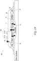
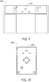
- FIG. 2A illustrates a side view of a negative pressure therapy system 200
- FIG. 2B illustrates a top view of the negative pressure therapy system 200
- the negative pressure therapy system 200 can be an example implementation of the negative pressure therapy system 100.
- the wound dressing 13 of the TNP apparatus 11 is shown as attached to the wound 14. Arrows depict the flow of air through the wound dressing 13 and wound exudate from the wound 14.
- the TNP apparatus 11 can include an air exhaust 26 and a component area 25, such as a components housing or storage area for components of the TNP apparatus 11 like one or more of the control circuitry 12A, memory device 12B, negative pressure source 12C, user interface 12D, power source 12E, first pressure sensor 12F, second pressure sensor 12G, and skin detector 12H.
- the user interface 12D of the negative pressure therapy system 200 can include a switch 21 (such as a dome switch), an interface element 22 (such as an electrical contact), a first indicator 23 (such as a first LED), and a second indicator 24 (such as a second LED).
- the switch 21 can receive a negative pressure activation or deactivation user input (for example, such as receiving the activation or deactivation user input in response to depression of the switch 21 for a period of time, like from between 0.5 seconds and 5 seconds).
- the interface element 22 can receive a negative pressure disable user input.
- the first indicator 23 and the second indicator 24 can indicate an operating status like functioning normally, under fault condition, or awaiting user input.
- the switch 21 or the interface element 22 can couple to a power supply connection of the negative pressure source 12C or the control circuitry 12A (such as a controller of the control circuitry 12A) or an enable signal of the negative pressure source 12C or the control circuitry 12A to activate or deactivate supply of negative pressure or disable supply of negative pressure.
- a SMT pin header may be used to activate or deactivate supply of negative pressure or disable supply of negative pressure.
- Component parts of the wound dressing 13 of the negative pressure therapy system 200 are illustrated to include an airlock layer 27, an absorbing layer 28, and a contact layer 29.
- the airlock layer 27 can enable air flow.
- the absorbing layer 28 can absorb wound exudate.
- the contact layer 29 can be soft and include silicon and be used to couple the TNP apparatus 11 to the patient.
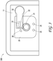
- FIG. 3 illustrates a top view of a negative pressure therapy system 300, which can be a more detailed example implementation of the negative pressure therapy system 200.
- the interface element 22 as shown can include an activating part 31 that may be molded in the film welded at position 32 to the wound dressing 13.
- the activating part 31 can be used to receive the user input for the interface element 22.
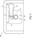
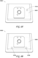
- FIG. 4 illustrates a top view of a negative pressure therapy system 400, which can be a more detailed example implementation of the negative pressure therapy system 200.
- the interface element 22 as shown can include a printed circuit board (PCB) 41 that may be flexible and built into a film for insertion and welded at position 42 to the wound dressing 13.
- the printed circuit board 41 can be used to receive the user input for the interface element 22.
- the locking mechanism of a zero insertion force (ZIF) connector may be used to improve retention.
- ZIF zero insertion force
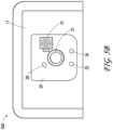
- FIGS. 5A and 5B illustrate a top view of a negative pressure therapy system 500, which can be a more detailed example implementation of the negative pressure therapy system 200.
- the interface element 22 as shown can include a conductive label 51 that can be used to complete an electrical contact when attached (see FIG. 5B ) and disconnect the electrical contact upon removal to receive the user input for the interface element 22.
- the locking mechanism of a ZIF connector may be used to improve retention.
- FIG. 6 illustrates a therapy control process 600 usable to control delivery of negative pressure therapy by an apparatus, such as the TNP apparatus 11.
- the therapy control process 600 is described in the context of the TNP apparatus 11, but may instead be implemented in other systems described herein or by other systems not shown.
- the therapy control process 600 can be performed, in some instances, by the control circuitry 12A of the TNP apparatus 11.
- the therapy control process 600 can determine whether a disable input was received from a user.
- the disable input may, for instance, be received from the user via the interface element 22. In some implementations, the disable input may not be provided by any user input to the TNP apparatus 11 other than via the interface element 22.
- the therapy control process 600 can disable supply of negative pressure.
- the supply of negative pressure can, for instance, be disabled by deactivation of operation of the negative pressure source 12C or the control circuitry 12A, opening of a vent positioned in the fluid flow path, and closing of a valve positioned in the fluid flow path.
- the therapy control process 600 can end.
- the TNP apparatus 11 may no longer be activated by user input to the switch 21, and the user may thus no longer be able to cause the TNP apparatus 11 to generate negative pressure.
- the therapy control process 600 can determine whether an activation input was received from the user.
- the activation input may, for instance, be received from the user via the switch 21. In some implementations, the activation input may not be provided by any user input to the TNP apparatus 11 other than via the switch 21.
- the therapy control process 600 can return to block 602 and again determine whether the disable input was received from the user.
- the therapy control process 600 can supply negative pressure.
- the supply of negative pressure can be performed by the negative pressure source 12C, and the negative pressure can be supplied to the wound dressing 13 via the fluid flow path.
- the therapy control process 600 can determine whether a deactivation input was received from the user.
- the deactivation input may, for instance, be received from the user via the switch 21. In some implementations, the deactivation input may not be provided by any user input to the TNP apparatus 11 other than via the switch 21.
- the therapy control process 600 can prevent the supply of negative pressure.
- the supply of negative pressure can, for instance, be prevented by one or more of deactivation of operation of the negative pressure source 12C, opening of a vent positioned in the fluid flow path, and closing of a valve positioned in the fluid flow path.
- the therapy control process 600 can return to block 602 and again determine whether the disable input was received from the user.
- the therapy control process 600 can determine whether the disable input was received from the user.
- the disable input may, for instance, be received from the user via the interface element 22. In some implementations, the disable input may not be provided by any user input to the TNP apparatus 11 other than via the interface element 22.
- block 614 is periodically executed while the TNP apparatus 11 provides negative pressure wound therapy in order to determine if supply of negative pressure should be disabled.
- the therapy control process 600 can return to block 608 and the supply of negative pressure can continue.
- the therapy control process 600 can disable supply of negative pressure.
- the supply of negative pressure can, for instance, be disabled by deactivation of operation of the negative pressure source 12C or the control circuitry 12A, opening of a vent positioned in the fluid flow path, and closing of a valve positioned in the fluid flow path.
- the therapy control process 600 can end.
- the TNP apparatus 11 may no longer be activated by user input to the switch 21, and the user may thus no longer be able to cause the TNP apparatus 11 to generate negative pressure.
- the TNP apparatus 11 may no longer be activated by user input to the switch 21 until an enable input is received, such as from the user via the interface element 22.
- the enable input may not be provided by any user input to the TNP apparatus 11 other than via the interface element 22.
- the supply of negative pressure may not stop by any user inputs other than the deactivation input or the disable input.
- FIGS. 7A, 7B, 7C illustrate connectors, which can be used with any of the embodiments of the negative pressure system described herein.
- FIG. 7A illustrates a header 700A with four circuits (or connectors) 70A, 70B, 70C, and 70D for connecting, for example, the switch 21 and the interface element 22 to each pair of circuits.
- FIG. 7B illustrates an SMT pin header 700B for connecting, for example, the switch 21 and the interface element 22.
- the switch 21 can be connected to the connector 72A and the interface element 22 can be connected to the connector 72B or vice versa.
- FIG. 7C illustrates a ZIF connector 700C having a terminal 74 to which the switch 21 or the interface element 22 can be connected. In some embodiments, two ZIF connectors 700C can be used for connecting each of the switch 21 and interface element 22.
- FIG. 8A illustrates a top view of a negative pressure therapy system 800A, which can be a more detailed example implementation of the negative pressure therapy system 200.
- a tab 810A can be pulled to rip an aperture in the wound dressing to force a gross leak along the dotted line 820A that causes termination of delivery of negative pressure.
- FIG. 8B illustrates a top view of a negative pressure therapy system 800B, which can be a more detailed example implementation of the negative pressure therapy system 200.
- Tabs 810B can be pulled to tear the wound dressing along the dotted line 820B to disrupt a power supply or electronics for the TNP apparatus (such as to remove a battery or electrical components) that causes termination of delivery of negative pressure.
- FIG. 9 illustrates components 900 of a negative pressure therapy system, which can be a more detailed example implementation of the negative pressure therapy system 200.
- the components 900 can illustrate that the batteries can be separated from control electronics, and the connection between the batteries and control electronics can be used as an activation function.
- the components 900 can include a surface mount connector 910 on an underside as illustrated.
- FIG. 10 illustrates components 1000 of a negative pressure therapy system, which can be a more detailed example implementation of the negative pressure therapy system 200.
- the components 1000 can include a surface mount connector 1010 on an upperside as illustrated.
- the components 1000 can illustrate that a main electric area can include a rigid PCB and have a connector on an uppermost surface to connect to a battery assembly.
- FIG. 11 illustrates components 1100 of a negative pressure therapy system, which can be a more detailed example implementation of the negative pressure therapy system 200.
- the components 1100 can illustrate an arrangement of repartitioned electronics relative to one or more other embodiments.
- the pump can be on one side, and batteries can be added as a pack.
- the pack could have silicone underside to adhere to the wound dressing.
- the components 1100 can include a surface mount connector on an underside as illustrated.
- FIG. 12 illustrates components 1200 of a negative pressure therapy system, which can be a more detailed example implementation of the negative pressure therapy system 200.
- the components 1200 can illustrate a top of a pump module with a surface mount connector 1210 still on an upperside.
- any value of a threshold, limit, duration, etc. provided herein is not intended to be absolute and, thereby, can be approximate.
- any threshold, limit, duration, etc. provided herein can be fixed or varied either automatically or by a user.
- relative terminology such as exceeds, greater than, less than, etc. in relation to a reference value is intended to also encompass being equal to the reference value. For example, exceeding a reference value that is positive can encompass being equal to or greater than the reference value.
- relative terminology such as exceeds, greater than, less than, etc. in relation to a reference value is intended to also encompass an inverse of the disclosed relationship, such as below, less than, greater than, etc. in relations to the reference value.
- blocks of the various processes may be described in terms of determining whether a value meets or does not meet a particular threshold, the blocks can be similarly understood, for example, in terms of a value (i) being below or above a threshold or (ii) satisfying or not satisfying a threshold.
- the various components illustrated in the figures may be implemented as software or firmware on a processor, controller, ASIC, FPGA, or dedicated hardware.
- Hardware components such as processors, ASICs, FPGAs, and the like, can include logic circuitry.
- User interface screens illustrated and described herein can include additional or alternative components. These components can include menus, lists, buttons, text boxes, labels, radio buttons, scroll bars, sliders, checkboxes, combo boxes, status bars, dialog boxes, windows, and the like. User interface screens can include additional or alternative information. Components can be arranged, grouped, displayed in any suitable order.
- the term "or” is used in its inclusive sense (and not in its exclusive sense) so that when used, for example, to connect a list of elements, the term “or” means one, some, or all of the elements in the list.
- the term “each,” as used herein, in addition to having its ordinary meaning, can mean any subset of a set of elements to which the term “each” is applied.
- the terms "generally parallel” and “substantially parallel” refer to a value, amount, or characteristic that departs from exactly parallel by less than or equal to 15 degrees, 10 degrees, 5 degrees, 3 degrees, 1 degree, or 0.1 degree.
- the language of the claims is to be interpreted broadly based on the language employed in the claims and not limited to the examples described in the present specification or during the prosecution of the application, which examples are to be construed as non-exclusive.
Landscapes
- Health & Medical Sciences (AREA)
- Heart & Thoracic Surgery (AREA)
- Veterinary Medicine (AREA)
- Engineering & Computer Science (AREA)
- Biomedical Technology (AREA)
- Life Sciences & Earth Sciences (AREA)
- Animal Behavior & Ethology (AREA)
- General Health & Medical Sciences (AREA)
- Public Health (AREA)
- Vascular Medicine (AREA)
- Anesthesiology (AREA)
- Hematology (AREA)
- Otolaryngology (AREA)
- Media Introduction/Drainage Providing Device (AREA)
- Surgical Instruments (AREA)
- External Artificial Organs (AREA)
Description
- This application claims the benefit of
U.S. Provisional Application No. 62/468,796, filed March 8, 2017 - Embodiments of the present disclosure relate to apparatuses for dressing and treating a wound with negative or reduced pressure therapy or topical negative pressure (TNP) therapy. In particular, but without limitation, embodiments disclosed herein relate to negative pressure therapy devices.
WO2007030601 discloses a self contained wound dressing with micropump. - The present invention is defined by the apparatus of
independent claim 1. Optional features of the invention are specified in the dependent claims. The methods described herein do not form part of the claimed invention. - In some embodiments, an apparatus for applying negative pressure to a wound is disclosed. The apparatus can include: a wound dressing configured to be placed over a wound of a patient; a negative pressure source disposed on or within the wound dressing, the negative pressure source configured to provide negative pressure to the wound dressing via a fluid flow path; a switch disposed on or within the wound dressing, the switch being configured to receive a first user input; an interface element disposed on or within the wound dressing, the interface element being configured to receive a second user input; and control circuitry. The control circuitry can be electrically coupled to the switch and the interface element. When in a first mode, the control circuitry can: supply of negative pressure with the negative pressure source in response to receipt of the first user input while the negative pressure source is not supplying negative pressure, prevent supply of negative pressure with the negative pressure source in response to receipt of the first user input while the negative pressure source is supplying negative pressure, and change from the first mode to a second mode different from the first mode in response to receipt of the second user input. When in a second mode, the control circuitry can disable supply of negative pressure with the negative pressure source.
- The apparatus of the preceding paragraph can include one or more of the following features: When the switch experiences a fault and is no longer able to receive the first user input, the control circuitry can prevent or disable supply of negative pressure with the negative pressure source in response to receipt of no user inputs other than the second user input. The control circuitry can supply of negative pressure with the negative pressure source in response to receipt of no user inputs other than the first user input. While the negative pressure source is supplying negative pressure, the control circuitry can prevent or disable supply of negative pressure with the negative pressure source in response to receipt of no user inputs other than the first user input and the second user input. When the control circuitry is in the second mode, the control circuitry can, in response to receipt of the second user input, change from the second mode to the first mode, and supply of negative pressure with the negative pressure source. The control circuitry can disable supply of negative pressure with the negative pressure source by deactivation of operation of the negative pressure source or the control circuitry, opening of a vent positioned in the fluid flow path, or closing of a valve positioned in the fluid flow path. The control circuitry can deactivate operation of the negative pressure source or the control circuitry by (i) disconnection of power to the negative pressure source or the control circuitry or (ii) withdrawal of an enable signal provided to the negative pressure source or the control circuitry. The control circuitry can prevent supply of negative pressure with the negative pressure source by deactivation of operation of the negative pressure source, opening of a vent positioned in the fluid flow path, and closing of a valve positioned in the fluid flow path. The interface element can be molded in film coupled to the wound dressing. The interface element can include an electrical contact configured to receive the second user input. The switch can receive the first user input in response to depression of the switch for a period of time. The period of time can be between 0.5 seconds and 5 seconds.
- A method of operating, using, or manufacturing the apparatus of the preceding two paragraphs is also disclosed.
- In some embodiments, a method of operating a negative pressure wound therapy apparatus comprising a wound dressing is disclosed. A negative pressure source can be disposed on or within the wound dressing, and a switch can be disposed on or within the wound dressing. An interface element can be disposed on or within the wound dressing, and the switch can receive a first user input and the interface element can receive a second user input. The method can include: supplying of negative pressure with the negative pressure source to the wound dressing via a fluid flow path in response to receipt of the first user input while the negative pressure source is not supplying negative pressure to the wound dressing; preventing supply of negative pressure with the negative pressure source to the wound dressing via the fluid flow path in response to receipt of the first user input while the negative pressure source is supplying negative pressure to the wound dressing; in response to receipt of the second user input, disabling supply of negative pressure with the negative pressure source to the wound dressing; and subsequent to said disabling supply of negative pressure, not supplying of negative pressure with the negative pressure source to the wound dressing via the fluid flow path in response to receipt of the first user input.
- The method of the preceding paragraph can include one or more of the following features: The method can further include, subsequent to the switch experiencing a fault and no longer being able to receive the first user input, preventing or disabling supply of negative pressure with the negative pressure source in response to receipt of no user inputs other than the second user input. The method can further include supplying of negative pressure with the negative pressure source in response to receipt of no user inputs other than the first user input. The method can further include, while the negative pressure source is supplying negative pressure, preventing or disabling supply of negative pressure with the negative pressure source in response to receipt of no user inputs other than the first user input and the second user input. The disabling supply of negative pressure can include deactivation of operation of the negative pressure source or the control circuitry, opening of a vent positioned in the fluid flow path, or closing of a valve positioned in the fluid flow path. The method can further include receiving the second user input via an electrical contact of the interface element. The method can further include receiving the first user input in response to depression of the switch for a period of time. The period of time can be between 0.5 seconds and 5 seconds.
- Features and advantages of the present disclosure will be apparent from the following detailed description, taken in conjunction with the accompanying drawings of which:
-
FIG. 1 illustrates a negative pressure therapy system according to some embodiments. -
FIGS. 2A and2B respectively illustrate a side view and top view of a negative pressure therapy system according to some embodiments, such as the negative pressure therapy system ofFIG. 1 . -
FIGS. 3 ,4 ,5A , and5B illustrate top views of negative pressure therapy systems according to some embodiments, such as the negative pressure therapy system ofFIGS. 2A and2B . -
FIG. 6 illustrates a therapy control process performable by a negative pressure therapy system according to some embodiments. -
FIGS. 7A, 7B, and 7C illustrate connectors according to some embodiments. -
FIGS. 8A and 8B illustrate top views of negative pressure therapy systems according to some embodiments, such as the negative pressure therapy system ofFIGS. 2A and2B . -
FIGS. 9, 10 ,11, and 12 illustrate components of negative pressure therapy systems according to some embodiments, such as the negative pressure therapy system ofFIGS. 2A and2B . - The present disclosure relates to methods and apparatuses for dressing and treating a wound with reduced pressure therapy or topical negative pressure (TNP) therapy. In particular, but without limitation, embodiments of this disclosure relate to negative pressure therapy apparatuses. The methods and apparatuses can incorporate or implement any combination of the features described below.
- Many different types of wound dressings are known for aiding in the healing process of a human or animal. These different types of wound dressings include many different types of materials and layers, for example, gauze, pads, foam pads or multi-layer wound dressings. TNP therapy, sometimes referred to as vacuum assisted closure, negative pressure wound therapy, or reduced pressure wound therapy, can be a beneficial mechanism for improving the healing rate of a wound. Such therapy is applicable to a broad range of wounds such as incisional wounds, open wounds and abdominal wounds or the like.
- TNP therapy can assist in the closure and healing of wounds by reducing tissue oedema, encouraging blood flow, stimulating the formation of granulation tissue, removing excess exudates, and reducing bacterial load and thus, infection to the wound. Furthermore, TNP therapy can permit less outside disturbance of the wound and promote more rapid healing.
- As is used herein, reduced or negative pressure levels, such as -X mmHg, represent pressure levels that are below atmospheric pressure, which typically corresponds to 760 mmHg (or 1 atm, 29.93 inHg, 101.325 kPa, 14.696 psi, etc.). Accordingly, a negative pressure value of -X mmHg reflects pressure that is X mmHg below atmospheric pressure, such as a pressure of (760-X) mmHg. In addition, negative pressure that is "less" or "smaller" than -X mmHg corresponds to pressure that is closer to atmospheric pressure (e.g., -40 mmHg is less than -60 mmHg). Negative pressure that is "more" or "greater" than -X mmHg corresponds to pressure that is further from atmospheric pressure (e.g., -80 mmHg is more than -60 mmHg).
- The user interfaces of some TNP apparatuses may have a limited elements through which a user can provide user input. In some instances, particular user interfaces may include just a single element usable by the user to stop and start delivery of negative pressure, and the user may not be able to replace or interchange the single element with another element. These particular user interfaces can desirably be easier to construct and operate than more complicated user interfaces having numerous elements. However, the particular user interfaces may present a problem if the single element experiences a fault (for example, a failure) and is no longer able to function to receive user input. The user of the particular user interfaces may undesirably be unable to start delivery of negative pressure if negative pressure is not already being provided and stop delivery of negative pressure if negative pressure is being provided.
- The situation of a user being unable to stop delivery of negative pressure can additionally introduce risks to the healing of a wound of a patient. If the patient experiences discomfort from the wound dressing during delivery of negative pressure and the single element experiences is no longer able to function to receive user input, the patient may be forced to remove the wound dressing to terminate delivery of negative pressure. The removal of the wound dressing can damage the wound of the patient and hinder any healing trajectory that was already progressed, as well as exposing the wound to external contaminants due to a loss of protection from the wound dressing.
- To address the situation of the user being unable to stop delivery of negative pressure, a TNP apparatus with the single element usable by the user to stop and start delivery of negative pressure can include another mechanism, such as another redundant mechanism, to stop delivery of negative pressure. In some implementations, a header circuit with four circuits could be used, and each pair of circuits could be used to deactivate operation by one or more means. One pair of the circuit could be used to connect to a power supply of the TNP apparatus, and the other pair of circuits could be used to connect to an enable signal (for example, a control circuitry enable signal). Additionally or alternatively, a surface mount technology (SMT) pin header could be used. The another mechanism can, for instance, be an activating part molded in a film that may be welded to the wound dressing so that the activating mechanism may not be easily lost. Additionally or alternatively, the locking mechanism of a zero insertion force (ZIF) connector may be used to improve retention. The activating mechanism can, in another example, be a printed circuit board (PCB), such as a flexible PCB, built into a film for insertion. The activating mechanism can, in yet another example, include a conductive label that completes the circuit when attached and is removable to stop delivery of negative pressure. In some implementations, a tab may additionally or alternatively be used, and the tab may, for instance, be pulled to disrupt a power supply for the TNP apparatus (such as to remove a battery) or pulled to rip an aperture in the wound dressing (such as by pulling a tab on an outside of the wound dressing) to force a gross leak that causes termination of delivery of negative pressure.
-
FIG. 1 illustrates a negativepressure therapy system 100 that includes aTNP apparatus 11 and awound 14. TheTNP apparatus 11 can be used to treat thewound 14. TheTNP apparatus 11 can includecontrol circuitry 12A,memory 12B, anegative pressure source 12C, auser interface 12D, apower source 12E, afirst pressure sensor 12F, asecond pressure sensor 12G, and askin detector 12H that are configured to electrically communicate with one another. In addition, theTNP apparatus 11 can include a wound dressing 13. Thepower source 12E can provide power to one or more components of theTNP apparatus 11. - One or more of the
control circuitry 12A,memory device 12B,negative pressure source 12C,user interface 12D,power source 12E,first pressure sensor 12F,second pressure sensor 12G, andskin detector 12H can be integral with, incorporated as part of, attached to, or disposed in the wound dressing 13. TheTNP apparatus 11 can accordingly be considered to have its control electronics and pump on-board the wound dressing 13 rather than separate from the wound dressing 13. - The
control circuitry 12A can include one or more controllers, activation circuits, boost converters, current limiters, feedback conditioning circuits, and H-bridge inverters. The one or more controllers can control the operations of one or more other components of theTNP apparatus 11 according at least to instructions stored in thememory device 12B. The one or more controllers can, for instance, control operations of thenegative pressure source 12C via a signal input (for example, a pulse width modulation of the signal) to the one or more H-bridge inverters, which in turn drive power from thepower source 12E to thenegative pressure source 12C. - The
negative pressure source 12C can include a pump, such as, without limitation, a rotary diaphragm pump or other diaphragm pump, a piezoelectric pump, a peristaltic pump, a piston pump, a rotary vane pump, a liquid ring pump, a scroll pump, a pump operated by a piezoelectric transducer, a voice coil pump, or any other suitable pump or micropump or any combinations of the foregoing. - The
user interface 12D can include one or more elements that receive user inputs or provide user outputs to a patient or caregiver. The one or more elements that receive user inputs can include buttons, switches, dials, touch screens, or the like, and the one or more elements that provide user outputs can include activation of a light emitting diode (LED) or one or more pixels of the display or activation of a speaker or the like. In one example, theuser interface 12D can include a switch to receive a first user input (for instance, a negative pressure activation or deactivation input), an interface element to receive a second user input (for instance, a negative pressure disable input), and two LEDs to indicate an operating status (for example, functioning normally, under fault condition, or awaiting user input) of theTNP apparatus 11. - The
first pressure sensor 12F can be used to monitor pressure underneath the wound dressing 13, such as pressure in a fluid flow path connecting thenegative pressure source 12C and thewound 14, pressure at thewound 14, or pressure in thenegative pressure source 12C. Thesecond pressure sensor 12G can be used to monitor pressure external to the wound dressing 13. The pressure external to the wound dressing can be atmospheric pressure; however, the atmospheric pressure can vary depending on, for instance, an altitude of use or pressurized environment in which theTNP apparatus 11 may be used. - The
control circuitry 12A can control the supply of negative pressure by thenegative pressure source 12C according at least to a comparison between the pressure monitored by thefirst pressure sensor 12F and the pressure monitored by thesecond pressure sensor 12G. Thecontrol circuitry 12A can include a controller, such as a microcontroller or microprocessor. - The
skin detector 12H can be used to determine if the wound dressing 13 has been placed over thewound 14. Theskin detector 12H can, for example, detect skin of a patient. The detection by theskin detector 12H can confirm whether the wound dressing 13 is coupled to skin of the patient next to thewound 14. When skin is detected, this may indicate that activation of theTNP apparatus 11 is intentional rather than unintentional and can thus be used to prevent unintentional activation of theTNP apparatus 11 or an end-of-life timer of theTNP apparatus 11, such as during transportation or manufacture of theTNP apparatus 11. In one example, if theskin detector 12H indicates to thecontrol circuitry 12A that skin is detected, thecontrol circuitry 12A can activate thenegative pressure source 12C to supply negative pressure in response to receiving an activation input via theuser interface 12D. If theskin detector 12H, on the other hand, indicates to thecontrol circuitry 12A that skin is not detected, thecontrol circuitry 12A may not activate thenegative pressure source 12C to supply negative pressure in response to receiving an activation input via theuser interface 12D. Theskin detector 12H can include one or more of a capacitive sensor, an impedance sensor, an optical sensor, a piezoresistive sensor, a piezoelectric sensor, an elastoresistive sensor, and an electrochemical sensor. - The wound dressing 13 can include a wound contact layer, a spacer layer, and an absorbent layer. The wound contact layer can be in contact with the
wound 14. The wound contact layer can include an adhesive on the patient facing side for securing the dressing to the skin surrounding thewound 14 or on the top side for securing the wound contact layer to a cover layer or other layer of the wound dressing 13. In operation, the wound contact layer can provide unidirectional flow so as to facilitate removal of exudate from the wound while blocking or substantially preventing exudate from returning to thewound 14. The spacer layer can assist in distributing negative pressure over the wound site and facilitating transport of wound exudate and fluids into the wound dressing 13. Further, the absorbent layer can absorb and retain exudate aspirated from thewound 14. - The
control circuitry 12A can, in some instances, prevent supply of negative pressure with thenegative pressure source 12C. For example, thecontrol circuitry 12A can prevent supply of negative pressure by deactivating operation of the negative pressure source, opening a vent positioned in the fluid flow path, and closing a valve positioned in the fluid flow path. - The supply of negative pressure with the
negative pressure source 12C can, in some instances, be disabled. For example, supply of negative pressure can be disabled by deactivating operation of thenegative pressure source 12C or thecontrol circuitry 12A, opening a vent positioned in the fluid flow path, and closing a valve positioned in the fluid flow path. In some implementations, deactivating operation of thenegative pressure source 12C or thecontrol circuitry 12A can be performed by disconnection of power to thenegative pressure source 12C or thecontrol circuitry 12A or withdrawal of an enable signal provided to thenegative pressure source 12C or thecontrol circuitry 12A. - The
control circuitry 12A can monitor a duty cycle of thenegative pressure source 12C. As is used herein, the "duty cycle" can reflect the amount of time thenegative pressure source 12C is active or running over a period of time. In other words, the duty cycle can reflect time that thenegative pressure source 12C is in an active state as a fraction of total time under consideration. Duty cycle measurements can reflect a level of activity of thenegative pressure source 12C. For example, the duty cycle can indicate that thenegative pressure source 12C is operating normally, working hard, working extremely hard, etc. Moreover, the duty cycle measurements, such as periodic duty cycle measurements, can reflect various operating conditions, such as presence or severity of leaks, rate of flow of fluid (for instance, air, liquid, or solid exudate, etc.) aspirated from a wound, or the like. Based on the duty cycle measurements, such as by comparing the measured duty cycle with a set of thresholds (for instance, determined in calibration), the controller can execute or be programmed to execute algorithms or logic that control the operation of the system. For example, duty cycle measurements can indicate presence of a high leak, and thecontrol circuitry 12A can be programmed to indicate this condition to a user (for instance, patient, caregiver, or physician) or temporarily suspend or pause operation of the source of negative pressure in order to conserve power. - When the
TNP apparatus 11 may be used to treat thewound 14, the wound dressing 13 can create a substantially sealed or closed space around thewound 13 and under the wound dressing 13, and thefirst pressure sensor 12F can periodically or continuously measure or monitor a level of pressure in this space. Thecontrol circuitry 12A can control the level of pressure in the space between a first negative pressure set point limit and at least a second negative pressure set point limit. In some instances, the first set point limit can be approximately -70 mmHg, or from approximately -60 mmHg or less to approximately -80 mmHg or more. In some instances, the second set point limit can be approximately -90 mmHg, or from approximately -80 mmHg or less to approximately -100 mmHg or more. -
FIG. 2A illustrates a side view of a negativepressure therapy system 200, andFIG. 2B illustrates a top view of the negativepressure therapy system 200. The negativepressure therapy system 200 can be an example implementation of the negativepressure therapy system 100. - In the negative
pressure therapy system 200, the wound dressing 13 of theTNP apparatus 11 is shown as attached to thewound 14. Arrows depict the flow of air through the wound dressing 13 and wound exudate from thewound 14. TheTNP apparatus 11 can include anair exhaust 26 and acomponent area 25, such as a components housing or storage area for components of theTNP apparatus 11 like one or more of thecontrol circuitry 12A,memory device 12B,negative pressure source 12C,user interface 12D,power source 12E,first pressure sensor 12F,second pressure sensor 12G, andskin detector 12H. - The
user interface 12D of the negativepressure therapy system 200 can include a switch 21 (such as a dome switch), an interface element 22 (such as an electrical contact), a first indicator 23 (such as a first LED), and a second indicator 24 (such as a second LED). Theswitch 21 can receive a negative pressure activation or deactivation user input (for example, such as receiving the activation or deactivation user input in response to depression of theswitch 21 for a period of time, like from between 0.5 seconds and 5 seconds). Theinterface element 22 can receive a negative pressure disable user input. Thefirst indicator 23 and thesecond indicator 24 can indicate an operating status like functioning normally, under fault condition, or awaiting user input. In some implementations, theswitch 21 or theinterface element 22 can couple to a power supply connection of thenegative pressure source 12C or thecontrol circuitry 12A (such as a controller of thecontrol circuitry 12A) or an enable signal of thenegative pressure source 12C or thecontrol circuitry 12A to activate or deactivate supply of negative pressure or disable supply of negative pressure. Additionally or alternatively, a SMT pin header may be used to activate or deactivate supply of negative pressure or disable supply of negative pressure. - Component parts of the wound dressing 13 of the negative
pressure therapy system 200 are illustrated to include anairlock layer 27, an absorbinglayer 28, and acontact layer 29. Theairlock layer 27 can enable air flow. The absorbinglayer 28 can absorb wound exudate. Thecontact layer 29 can be soft and include silicon and be used to couple theTNP apparatus 11 to the patient. -
FIG. 3 illustrates a top view of a negativepressure therapy system 300, which can be a more detailed example implementation of the negativepressure therapy system 200. Theinterface element 22 as shown can include an activatingpart 31 that may be molded in the film welded atposition 32 to the wound dressing 13. The activatingpart 31 can be used to receive the user input for theinterface element 22. -
FIG. 4 illustrates a top view of a negativepressure therapy system 400, which can be a more detailed example implementation of the negativepressure therapy system 200. Theinterface element 22 as shown can include a printed circuit board (PCB) 41 that may be flexible and built into a film for insertion and welded atposition 42 to the wound dressing 13. The printedcircuit board 41 can be used to receive the user input for theinterface element 22. Moreover, the locking mechanism of a zero insertion force (ZIF) connector may be used to improve retention. -
FIGS. 5A and5B illustrate a top view of a negativepressure therapy system 500, which can be a more detailed example implementation of the negativepressure therapy system 200. Theinterface element 22 as shown can include aconductive label 51 that can be used to complete an electrical contact when attached (seeFIG. 5B ) and disconnect the electrical contact upon removal to receive the user input for theinterface element 22. Moreover, the locking mechanism of a ZIF connector may be used to improve retention. -
FIG. 6 illustrates atherapy control process 600 usable to control delivery of negative pressure therapy by an apparatus, such as theTNP apparatus 11. For convenience, thetherapy control process 600 is described in the context of theTNP apparatus 11, but may instead be implemented in other systems described herein or by other systems not shown. Thetherapy control process 600 can be performed, in some instances, by thecontrol circuitry 12A of theTNP apparatus 11. - At
block 602, thetherapy control process 600 can determine whether a disable input was received from a user. The disable input may, for instance, be received from the user via theinterface element 22. In some implementations, the disable input may not be provided by any user input to theTNP apparatus 11 other than via theinterface element 22. - If the disable input was received, at
block 604, thetherapy control process 600 can disable supply of negative pressure. The supply of negative pressure can, for instance, be disabled by deactivation of operation of thenegative pressure source 12C or thecontrol circuitry 12A, opening of a vent positioned in the fluid flow path, and closing of a valve positioned in the fluid flow path. Afterblock 604, thetherapy control process 600 can end. In some implementations, afterblock 604, theTNP apparatus 11 may no longer be activated by user input to theswitch 21, and the user may thus no longer be able to cause theTNP apparatus 11 to generate negative pressure. - If the disable input was not received, at
block 606, thetherapy control process 600 can determine whether an activation input was received from the user. The activation input may, for instance, be received from the user via theswitch 21. In some implementations, the activation input may not be provided by any user input to theTNP apparatus 11 other than via theswitch 21. - If the activation input was not received, the
therapy control process 600 can return to block 602 and again determine whether the disable input was received from the user. - On the other hand, if the activation input was received, at
block 608, thetherapy control process 600 can supply negative pressure. The supply of negative pressure can be performed by thenegative pressure source 12C, and the negative pressure can be supplied to the wound dressing 13 via the fluid flow path. - At
block 610, thetherapy control process 600 can determine whether a deactivation input was received from the user. The deactivation input may, for instance, be received from the user via theswitch 21. In some implementations, the deactivation input may not be provided by any user input to theTNP apparatus 11 other than via theswitch 21. - If the deactivation input was received, at
block 612, thetherapy control process 600 can prevent the supply of negative pressure. The supply of negative pressure can, for instance, be prevented by one or more of deactivation of operation of thenegative pressure source 12C, opening of a vent positioned in the fluid flow path, and closing of a valve positioned in the fluid flow path. Afterblock 612, thetherapy control process 600 can return to block 602 and again determine whether the disable input was received from the user. - If the deactivation input was received, at
block 614, thetherapy control process 600 can determine whether the disable input was received from the user. The disable input may, for instance, be received from the user via theinterface element 22. In some implementations, the disable input may not be provided by any user input to theTNP apparatus 11 other than via theinterface element 22. In some embodiments, block 614 is periodically executed while theTNP apparatus 11 provides negative pressure wound therapy in order to determine if supply of negative pressure should be disabled. - If the disable input was not received, the
therapy control process 600 can return to block 608 and the supply of negative pressure can continue. - If the disable input was received, at
block 616, thetherapy control process 600 can disable supply of negative pressure. The supply of negative pressure can, for instance, be disabled by deactivation of operation of thenegative pressure source 12C or thecontrol circuitry 12A, opening of a vent positioned in the fluid flow path, and closing of a valve positioned in the fluid flow path. Afterblock 616, thetherapy control process 600 can end. In some implementations, afterblock 616, theTNP apparatus 11 may no longer be activated by user input to theswitch 21, and the user may thus no longer be able to cause theTNP apparatus 11 to generate negative pressure. Additionally or alternatively, theTNP apparatus 11 may no longer be activated by user input to theswitch 21 until an enable input is received, such as from the user via theinterface element 22. In some implementations, the enable input may not be provided by any user input to theTNP apparatus 11 other than via theinterface element 22. - In some implementations of the
therapy control process 600, the supply of negative pressure may not stop by any user inputs other than the deactivation input or the disable input. -
FIGS. 7A, 7B, 7C illustrate connectors, which can be used with any of the embodiments of the negative pressure system described herein.FIG. 7A illustrates aheader 700A with four circuits (or connectors) 70A, 70B, 70C, and 70D for connecting, for example, theswitch 21 and theinterface element 22 to each pair of circuits.FIG. 7B illustrates anSMT pin header 700B for connecting, for example, theswitch 21 and theinterface element 22. In some implementations, theswitch 21 can be connected to theconnector 72A and theinterface element 22 can be connected to theconnector 72B or vice versa.FIG. 7C illustrates aZIF connector 700C having a terminal 74 to which theswitch 21 or theinterface element 22 can be connected. In some embodiments, twoZIF connectors 700C can be used for connecting each of theswitch 21 andinterface element 22. -
FIG. 8A illustrates a top view of a negativepressure therapy system 800A, which can be a more detailed example implementation of the negativepressure therapy system 200. Atab 810A can be pulled to rip an aperture in the wound dressing to force a gross leak along the dottedline 820A that causes termination of delivery of negative pressure.FIG. 8B illustrates a top view of a negativepressure therapy system 800B, which can be a more detailed example implementation of the negativepressure therapy system 200.Tabs 810B can be pulled to tear the wound dressing along the dottedline 820B to disrupt a power supply or electronics for the TNP apparatus (such as to remove a battery or electrical components) that causes termination of delivery of negative pressure. -
FIG. 9 illustratescomponents 900 of a negative pressure therapy system, which can be a more detailed example implementation of the negativepressure therapy system 200. Thecomponents 900 can illustrate that the batteries can be separated from control electronics, and the connection between the batteries and control electronics can be used as an activation function. Thecomponents 900 can include asurface mount connector 910 on an underside as illustrated. -
FIG. 10 illustratescomponents 1000 of a negative pressure therapy system, which can be a more detailed example implementation of the negativepressure therapy system 200. Thecomponents 1000 can include asurface mount connector 1010 on an upperside as illustrated. Thecomponents 1000 can illustrate that a main electric area can include a rigid PCB and have a connector on an uppermost surface to connect to a battery assembly. -
FIG. 11 illustratescomponents 1100 of a negative pressure therapy system, which can be a more detailed example implementation of the negativepressure therapy system 200. Thecomponents 1100 can illustrate an arrangement of repartitioned electronics relative to one or more other embodiments. The pump can be on one side, and batteries can be added as a pack. The pack could have silicone underside to adhere to the wound dressing. Thecomponents 1100 can include a surface mount connector on an underside as illustrated. -
FIG. 12 illustratescomponents 1200 of a negative pressure therapy system, which can be a more detailed example implementation of the negativepressure therapy system 200. Thecomponents 1200 can illustrate a top of a pump module with asurface mount connector 1210 still on an upperside. - Any value of a threshold, limit, duration, etc. provided herein is not intended to be absolute and, thereby, can be approximate. In addition, any threshold, limit, duration, etc. provided herein can be fixed or varied either automatically or by a user. Furthermore, as is used herein relative terminology such as exceeds, greater than, less than, etc. in relation to a reference value is intended to also encompass being equal to the reference value. For example, exceeding a reference value that is positive can encompass being equal to or greater than the reference value. In addition, as is used herein relative terminology such as exceeds, greater than, less than, etc. in relation to a reference value is intended to also encompass an inverse of the disclosed relationship, such as below, less than, greater than, etc. in relations to the reference value. Moreover, although blocks of the various processes may be described in terms of determining whether a value meets or does not meet a particular threshold, the blocks can be similarly understood, for example, in terms of a value (i) being below or above a threshold or (ii) satisfying or not satisfying a threshold.
- Features, materials, characteristics, or groups described in conjunction with a particular aspect, embodiment, or example are to be understood to be applicable to any other aspect, embodiment or example described herein unless incompatible therewith. All of the features disclosed in this specification (including any accompanying claims, abstract, and drawings), or all of the steps of any method or process so disclosed, may be combined in any combination, except combinations where at least some of such features or steps are mutually exclusive. The protection is not restricted to the details of any foregoing embodiments. The protection extends to any novel one, or any novel combination, of the features disclosed in this specification (including any accompanying claims, abstract and drawings), or to any novel one, or any novel combination, of the steps of any method or process so disclosed.
- While certain embodiments have been described, these embodiments have been presented by way of example only, and are not intended to limit the scope of protection. Indeed, the novel methods and systems described herein may be embodied in a variety of other forms. Furthermore, various omissions, substitutions and changes in the form of the methods and systems described herein may be made. Those skilled in the art will appreciate that in some embodiments, the actual steps taken in the processes illustrated or disclosed may differ from those shown in the figures. Depending on the embodiment, certain of the steps described above may be removed, others may be added. For example, the actual steps or order of steps taken in the disclosed processes may differ from those shown in the figure. Depending on the embodiment, certain of the steps described above may be removed, others may be added. For instance, the various components illustrated in the figures may be implemented as software or firmware on a processor, controller, ASIC, FPGA, or dedicated hardware. Hardware components, such as processors, ASICs, FPGAs, and the like, can include logic circuitry. Furthermore, the features and attributes of the specific embodiments disclosed above may be combined in different ways to form additional embodiments, all of which fall within the scope of the present disclosure.
- User interface screens illustrated and described herein can include additional or alternative components. These components can include menus, lists, buttons, text boxes, labels, radio buttons, scroll bars, sliders, checkboxes, combo boxes, status bars, dialog boxes, windows, and the like. User interface screens can include additional or alternative information. Components can be arranged, grouped, displayed in any suitable order.
- Although the present disclosure includes certain embodiments, examples and applications, it will be understood by those skilled in the art that the present disclosure extends beyond the specifically disclosed embodiments to other alternative embodiments or uses and obvious modifications thereof, including embodiments which do not provide all of the features and advantages set forth herein. Accordingly, the scope of the present disclosure is not intended to be limited by the specific disclosures of preferred embodiments herein, and is defined by the claims.
- Conditional language, such as "can," "could," "might," or "may," unless specifically stated otherwise, or otherwise understood within the context as used, is generally intended to convey that certain embodiments include, while other embodiments do not include, certain features, elements, or steps. Thus, such conditional language is not generally intended to imply that features, elements, or steps are in any way required for one or more embodiments or that one or more embodiments necessarily include logic for deciding, with or without user input or prompting, whether these features, elements, or steps are included or are to be performed in any particular embodiment. The terms "comprising," "including," "having," and the like are synonymous and are used inclusively, in an open-ended fashion, and do not exclude additional elements, features, acts, operations, and so forth. Also, the term "or" is used in its inclusive sense (and not in its exclusive sense) so that when used, for example, to connect a list of elements, the term "or" means one, some, or all of the elements in the list. Further, the term "each," as used herein, in addition to having its ordinary meaning, can mean any subset of a set of elements to which the term "each" is applied.
- Conjunctive language such as the phrase "at least one of X, Y, and Z," unless specifically stated otherwise, is otherwise understood with the context as used in general to convey that an item, term, etc. may be either X, Y, or Z. Thus, such conjunctive language is not generally intended to imply that certain embodiments require the presence of at least one of X, at least one of Y, and at least one of Z.
- Language of degree used herein, such as the terms "approximately," "about," "generally," and "substantially" as used herein represent a value, amount, or characteristic close to the stated value, amount, or characteristic that still performs a desired function or achieves a desired result. For example, the terms "approximately", "about", "generally," and "substantially" may refer to an amount that is within less than 10% of, within less than 5% of, within less than 1% of, within less than 0.1% of, and within less than 0.01% of the stated amount. As another example, in certain embodiments, the terms "generally parallel" and "substantially parallel" refer to a value, amount, or characteristic that departs from exactly parallel by less than or equal to 15 degrees, 10 degrees, 5 degrees, 3 degrees, 1 degree, or 0.1 degree. The language of the claims is to be interpreted broadly based on the language employed in the claims and not limited to the examples described in the present specification or during the prosecution of the application, which examples are to be construed as non-exclusive.
Claims (12)
- An apparatus for applying negative pressure to a wound, the apparatus comprising:a wound dressing (13) configured to be placed over a wound of a patient;a negative pressure source (12C) disposed on or within the wound dressing, the negative pressure source configured to provide negative pressure to the wound dressing via a fluid flow path;a switch (21) disposed on or within the wound dressing, the switch being configured to receive a first user input;an interface element (22) disposed on or within the wound dressing, the interface element being configured to receive a second user input; andcontrol circuitry electrically coupled to the switch and the interface element, the control circuitry being configured to:when in a first mode,supply of negative pressure with the negative pressure source in response to receipt of the first user input while the negative pressure source is not supplying negative pressure, prevent supply of negative pressure with the negative pressure source in response to receipt of the first user input while the negative pressure source is supplying negative pressure, andchange from the first mode to a second mode different from the first mode in response to receipt of the second user input,when in the second mode, disable supply of negative pressure with the negative pressure source.
- The apparatus of claim 1, wherein when the switch experiences a fault and is no longer able to receive the first user input, the control circuitry is further configured to prevent or disable supply of negative pressure with the negative pressure source in response to receipt of no user inputs other than the second user input.
- The apparatus of claim 1, wherein the control circuitry is further configured to supply of negative pressure with the negative pressure source in response to receipt of no user inputs other than the first user input.
- The apparatus of claim 1, wherein while the negative pressure source is supplying negative pressure, the control circuitry is further configured to prevent or disable supply of negative pressure with the negative pressure source in response to receipt of no user inputs other than the first user input and the second user input.
- The apparatus of claim 1, wherein when the control circuitry is in the second mode, the control circuitry is, in response to receipt of the second user input, further configured to:change from the second mode to the first mode; andsupply of negative pressure with the negative pressure source.
- The apparatus of claim 1, wherein the control circuitry is configured to disable supply of negative pressure with the negative pressure source by: deactivation of operation of the negative pressure source or the control circuitry, opening of a vent positioned in the fluid flow path, or closing of a valve positioned in the fluid flow path.
- The apparatus of claim 6, wherein the control circuitry is configured to deactivate operation of the negative pressure source or the control circuitry by (i) disconnection of power to the negative pressure source or the control circuitry or (ii) withdrawal of an enable signal provided to the negative pressure source or the control circuitry.
- The apparatus of claim 1, wherein the control circuitry is configured to prevent supply of negative pressure with the negative pressure source by: deactivation of operation of the negative pressure source, opening of a vent positioned in the fluid flow path, or closing of a valve positioned in the fluid flow path.
- The apparatus of claim 1, wherein the interface element is molded in film coupled to the wound dressing.
- The apparatus of claim 1, wherein the interface element comprises an electrical contact configured to receive the second user input.
- The apparatus of claim 1, wherein the switch is configured to receive the first user input in response to depression of the switch for a period of time.
- The apparatus of claim 11, wherein the period of time is between 0.5 seconds and 5 seconds.
Applications Claiming Priority (2)
| Application Number | Priority Date | Filing Date | Title |
|---|---|---|---|
| US201762468796P | 2017-03-08 | 2017-03-08 | |
| PCT/EP2018/055698 WO2018162613A1 (en) | 2017-03-08 | 2018-03-08 | Negative pressure wound therapy device control in presence of fault condition |
Publications (2)
| Publication Number | Publication Date |
|---|---|
| EP3592312A1 EP3592312A1 (en) | 2020-01-15 |
| EP3592312B1 true EP3592312B1 (en) | 2024-01-10 |
Family
ID=61617018
Family Applications (1)
| Application Number | Title | Priority Date | Filing Date |
|---|---|---|---|
| EP18710032.6A Active EP3592312B1 (en) | 2017-03-08 | 2018-03-08 | Negative pressure wound therapy device control in presence of fault condition |
Country Status (8)
| Country | Link |
|---|---|
| US (2) | US11123471B2 (en) |
| EP (1) | EP3592312B1 (en) |
| JP (1) | JP7361606B2 (en) |
| CN (1) | CN110582257B (en) |
| AU (1) | AU2018229808B2 (en) |
| CA (1) | CA3055664A1 (en) |
| WO (1) | WO2018162613A1 (en) |
| ZA (1) | ZA201905812B (en) |
Families Citing this family (34)
| Publication number | Priority date | Publication date | Assignee | Title |
|---|---|---|---|---|
| GB0808376D0 (en) | 2008-05-08 | 2008-06-18 | Bristol Myers Squibb Co | Wound dressing |
| GB0817796D0 (en) | 2008-09-29 | 2008-11-05 | Convatec Inc | wound dressing |
| GB201020236D0 (en) | 2010-11-30 | 2011-01-12 | Convatec Technologies Inc | A composition for detecting biofilms on viable tissues |
| CA2819475C (en) | 2010-12-08 | 2019-02-12 | Convatec Technologies Inc. | Integrated system for assessing wound exudates |
| CA2819549C (en) | 2010-12-08 | 2019-09-10 | Convatec Technologies Inc. | Wound exudate system accessory |
| GB201115182D0 (en) | 2011-09-02 | 2011-10-19 | Trio Healthcare Ltd | Skin contact material |
| GB2497406A (en) | 2011-11-29 | 2013-06-12 | Webtec Converting Llc | Dressing with a perforated binder layer |
| CN105008611A (en) | 2012-12-20 | 2015-10-28 | 康沃特克科技公司 | Processing of chemically modified cellulosic fibres |
| CN109564213B (en) | 2016-03-30 | 2023-01-31 | 西诺福有限公司 | Detecting microbial wound infection |
| MX2018011801A (en) | 2016-03-30 | 2019-12-16 | Convatec Technologies Inc | Detecting microbial infections in wounds. |
| AU2017256692B2 (en) | 2016-04-26 | 2022-03-03 | Smith & Nephew Plc | Wound dressings and methods of use with integrated negative pressure source having a fluid ingress inhibition component |
| EP3452129B1 (en) | 2016-05-03 | 2022-03-23 | Smith & Nephew plc | Negative pressure wound therapy device activation and control |
| CA3038206A1 (en) | 2016-05-03 | 2017-11-09 | Smith & Nephew Plc | Optimizing power transfer to negative pressure sources in negative pressure therapy systems |
| WO2017191158A1 (en) | 2016-05-03 | 2017-11-09 | Smith & Nephew Plc | Systems and methods for driving negative pressure sources in negative pressure therapy systems |
| AU2017292881B2 (en) | 2016-07-08 | 2022-03-17 | Convatec Technologies Inc. | Flexible negative pressure system |
| EP3481348A4 (en) | 2016-07-08 | 2020-02-26 | ConvaTec Technologies Inc. | Fluid collection apparatus |
| PL3481360T3 (en) | 2016-07-08 | 2022-05-02 | Convatec Technologies Inc. | Fluid flow sensing |
| EP3503857B1 (en) | 2016-08-25 | 2024-04-17 | Smith & Nephew plc | Absorbent negative pressure wound therapy dressing |
| US11564847B2 (en) | 2016-09-30 | 2023-01-31 | Smith & Nephew Plc | Negative pressure wound treatment apparatuses and methods with integrated electronics |
| AU2018229808B2 (en) | 2017-03-08 | 2024-04-11 | Smith & Nephew Plc | Negative pressure wound therapy device control in presence of fault condition |
| WO2018206420A1 (en) | 2017-05-09 | 2018-11-15 | Smith & Nephew Plc | Redundant controls for negative pressure wound therapy systems |
| GB201718070D0 (en) | 2017-11-01 | 2017-12-13 | Smith & Nephew | Negative pressure wound treatment apparatuses and methods with integrated electronics |
| JP7394746B2 (en) | 2017-09-13 | 2023-12-08 | スミス アンド ネフュー ピーエルシー | Negative pressure wound therapy device and method with integrated electronics |
| GB201718072D0 (en) | 2017-11-01 | 2017-12-13 | Smith & Nephew | Negative pressure wound treatment apparatuses and methods with integrated electronics |
| US11497653B2 (en) | 2017-11-01 | 2022-11-15 | Smith & Nephew Plc | Negative pressure wound treatment apparatuses and methods with integrated electronics |
| GB201718054D0 (en) | 2017-11-01 | 2017-12-13 | Smith & Nephew | Sterilization of integrated negative pressure wound treatment apparatuses and sterilization methods |
| WO2019157466A1 (en) | 2018-02-12 | 2019-08-15 | Healyx Labs, Inc. | Negative pressure wound therapy systems, devices, and methods |
| USD898925S1 (en) | 2018-09-13 | 2020-10-13 | Smith & Nephew Plc | Medical dressing |
| US20220088288A1 (en) * | 2018-12-26 | 2022-03-24 | Kci Licensing, Inc. | Piezoelectric pump adapter for negative-pressure therapy |
| US11484640B2 (en) * | 2019-07-03 | 2022-11-01 | T.J.Smith And Nephew, Limited | Negative pressure wound therapy dressing recognition, wound status detection, and therapy adjustment |
| US11766822B2 (en) | 2019-08-20 | 2023-09-26 | 3M Innovative Properties Company | Microstructured surface with increased microorganism removal when cleaned, articles and methods |
| US11331221B2 (en) | 2019-12-27 | 2022-05-17 | Convatec Limited | Negative pressure wound dressing |
| US11771819B2 (en) | 2019-12-27 | 2023-10-03 | Convatec Limited | Low profile filter devices suitable for use in negative pressure wound therapy systems |
| CN114469518B (en) * | 2022-01-27 | 2023-02-21 | 长沙海润生物技术有限公司 | Dressing for negative-voltage electric field coupling strong-oxygen therapy |
Family Cites Families (354)
| Publication number | Priority date | Publication date | Assignee | Title |
|---|---|---|---|---|
| US3874387A (en) | 1972-07-05 | 1975-04-01 | Pasquale P Barbieri | Valved hemostatic pressure cap |
| US4224941A (en) | 1978-11-15 | 1980-09-30 | Stivala Oscar G | Hyperbaric treatment apparatus |
| US4398910A (en) | 1981-02-26 | 1983-08-16 | Blake L W | Wound drain catheter |
| US4534356A (en) | 1982-07-30 | 1985-08-13 | Diamond Shamrock Chemicals Company | Solid state transcutaneous blood gas sensors |
| US4569674A (en) | 1982-08-03 | 1986-02-11 | Stryker Corporation | Continuous vacuum wound drainage system |
| DE3323973A1 (en) | 1983-07-02 | 1985-01-03 | Boehringer Mannheim Gmbh, 6800 Mannheim | ERYTHROCYTE RETENTION SUBSTRATES |
| US4624656A (en) | 1983-07-25 | 1986-11-25 | Hospitak, Inc. | Hyperbaric gas treatment device |
| DE3441891A1 (en) | 1984-11-16 | 1986-05-28 | Walter Beck | METHOD AND DEVICE FOR SUCTIONING SECRETARY LIQUID FROM A Wound |
| DE3601363A1 (en) | 1986-01-18 | 1988-12-29 | Stierlen Maquet Ag | ELECTRICAL SWITCHING ELEMENT |
| US5527293A (en) | 1989-04-03 | 1996-06-18 | Kinetic Concepts, Inc. | Fastening system and method |
| US5056510A (en) | 1989-04-13 | 1991-10-15 | The Kendall Company | Vented wound dressing |
| US4979944A (en) | 1989-08-21 | 1990-12-25 | The Pullman Company | Surgical vacuum evacuation device |
| US5181905A (en) | 1989-11-28 | 1993-01-26 | Eric Flam | Method of monitoring the condition of the skin or wound |
| US5152757A (en) | 1989-12-14 | 1992-10-06 | Brigham And Women's Hospital | System for diagnosis and treatment of wounds |
| US5055198A (en) | 1990-03-07 | 1991-10-08 | Shettigar U Ramakrishna | Autologous blood recovery membrane system and method |
| US5340968A (en) | 1991-05-07 | 1994-08-23 | Nippondenso Company, Ltd. | Information storage medium with electronic and visual areas |
| JPH04354722A (en) | 1991-05-30 | 1992-12-09 | Nippondenso Co Ltd | Electronic tag |
| US5636643A (en) | 1991-11-14 | 1997-06-10 | Wake Forest University | Wound treatment employing reduced pressure |
| US5266928A (en) | 1992-05-29 | 1993-11-30 | Johnson Lonnie G | Wet diaper detector |
| US5964723A (en) | 1992-06-19 | 1999-10-12 | Augustine Medical, Inc. | Normothermic tissue heating wound covering |
| USD357743S (en) | 1992-12-31 | 1995-04-25 | Alza Corporation | Electrotransport drug delivery system |
| US5902256A (en) | 1993-02-12 | 1999-05-11 | Jb Research, Inc. | Massage unit with replaceable hot and cold packs |
| GB9400994D0 (en) | 1994-01-20 | 1994-03-16 | Bristol Myers Squibb Co | Wound dressing |
| US5549584A (en) | 1994-02-14 | 1996-08-27 | The Kendall Company | Apparatus for removing fluid from a wound |
| ZA956968B (en) | 1994-08-22 | 1996-03-29 | Kinetic Concepts Inc | Wound drainage equipment |
| US6599262B1 (en) | 1994-12-07 | 2003-07-29 | Masini Michael A | Bandage with thermal insert |
| US6225523B1 (en) | 1994-12-07 | 2001-05-01 | Masini Michael A | Invertible wound dressings and method of making the same |
| US5643189A (en) | 1994-12-07 | 1997-07-01 | Masini; Michael A. | Composite wound dressing including inversion means |
| US6261276B1 (en) | 1995-03-13 | 2001-07-17 | I.S.I. International, Inc. | Apparatus for draining surgical wounds |
| US5779657A (en) | 1995-07-21 | 1998-07-14 | Daneshvar; Yousef | Nonstretchable wound cover and protector |
| GB9523253D0 (en) | 1995-11-14 | 1996-01-17 | Mediscus Prod Ltd | Portable wound treatment apparatus |
| US6783328B2 (en) | 1996-09-30 | 2004-08-31 | Terumo Cardiovascular Systems Corporation | Method and apparatus for controlling fluid pumps |
| DE19722075C1 (en) | 1997-05-27 | 1998-10-01 | Wilhelm Dr Med Fleischmann | Medication supply to open wounds |
| US6071267A (en) | 1998-02-06 | 2000-06-06 | Kinetic Concepts, Inc. | Medical patient fluid management interface system and method |
| US6458109B1 (en) | 1998-08-07 | 2002-10-01 | Hill-Rom Services, Inc. | Wound treatment apparatus |
| US6168800B1 (en) | 1998-08-20 | 2001-01-02 | Medwrap Corporation | Antimcrobial multi-layer island dressing |
| DE19844355A1 (en) | 1998-09-28 | 2000-04-06 | Rainer E Sachse | Adhesive wound dressing of flexible, membrane like material penetrable by air comprises integrated device which drains wound secretions or produces reduced pressure, or can be connected to an external suction system |
| GB9822341D0 (en) | 1998-10-13 | 1998-12-09 | Kci Medical Ltd | Negative pressure therapy using wall suction |
| US6607495B1 (en) | 1999-06-18 | 2003-08-19 | University Of Virginia Patent Foundation | Apparatus for fluid transport and related method thereof |
| US6261283B1 (en) | 1999-08-31 | 2001-07-17 | Alcon Universal Ltd. | Liquid venting surgical system and cassette |
| JP4681185B2 (en) | 1999-11-29 | 2011-05-11 | ケーシーアイ メディカル リソーシーズ | Trauma treatment device |
| US6183438B1 (en) | 2000-01-04 | 2001-02-06 | Ramon Berguer | Catheter with centering wire |
| US20050119737A1 (en) | 2000-01-12 | 2005-06-02 | Bene Eric A. | Ocular implant and methods for making and using same |
| DE20000887U1 (en) | 2000-01-19 | 2001-06-07 | Riesinger Geb Dahlmann | Collection bag with suction device |
| US6794554B2 (en) | 2000-02-01 | 2004-09-21 | Ferris Pharmaceuticals, Inc. | Wound packing material |
| DE60135746D1 (en) | 2000-05-22 | 2008-10-23 | Arthur C Coffey | WOUND BRACELET WITH SIS LAYER AND VACUUM CHAMBER |
| US6685681B2 (en) | 2000-11-29 | 2004-02-03 | Hill-Rom Services, Inc. | Vacuum therapy and cleansing dressing for wounds |
| US6855135B2 (en) | 2000-11-29 | 2005-02-15 | Hill-Rom Services, Inc. | Vacuum therapy and cleansing dressing for wounds |
| US6976977B2 (en) | 2000-12-06 | 2005-12-20 | Sherwood Services Ag | Vacuum setting and indication system for a drainage device |
| JP4408018B2 (en) | 2001-01-18 | 2010-02-03 | ナワ−ハイルミッテル ゲーエムベーハー | Bandage and treatment solution used with the bandage |
| US7700819B2 (en) | 2001-02-16 | 2010-04-20 | Kci Licensing, Inc. | Biocompatible wound dressing |
| US7070584B2 (en) | 2001-02-20 | 2006-07-04 | Kci Licensing, Inc. | Biocompatible wound dressing |
| US7108683B2 (en) | 2001-04-30 | 2006-09-19 | Kci Licensing, Inc | Wound therapy and tissue management system and method with fluid differentiation |
| ATE530220T1 (en) | 2001-07-12 | 2011-11-15 | Kci Medical Resources | CONTROL OF VACUUM CHANGE RATE |
| US7004915B2 (en) | 2001-08-24 | 2006-02-28 | Kci Licensing, Inc. | Negative pressure assisted tissue treatment system |
| US6636010B1 (en) * | 2001-10-01 | 2003-10-21 | Zevex, Inc. | Precision dosage apparatus, system and method |
| US6787682B2 (en) | 2001-11-05 | 2004-09-07 | Hollister Incorporated | Absorbent foam wound dressing |
| US7645253B2 (en) | 2001-11-16 | 2010-01-12 | National Quality Care, Inc. | Wearable ultrafiltration device |
| US6648862B2 (en) | 2001-11-20 | 2003-11-18 | Spheric Products, Ltd. | Personally portable vacuum desiccator |
| GB2382305B (en) | 2001-11-23 | 2004-12-15 | Johnson & Johnson Medical Ltd | Absorbent wound dressings containing a hydrogel layer |
| EP1627662B1 (en) | 2004-06-10 | 2011-03-02 | Candela Corporation | Apparatus for vacuum-assisted light-based treatments of the skin |
| AU2002359828A1 (en) | 2001-12-26 | 2003-07-24 | Hill-Rom Services Inc. | Vented vacuum bandage and method |
| CA2468307A1 (en) | 2001-12-26 | 2003-07-17 | Hill-Rom Services, Inc. | Vacuum bandage packing |
| EP1487389B1 (en) | 2002-02-28 | 2011-10-05 | KCI Medical Resources | External catheter access to vacuum bandage |
| US6942633B2 (en) | 2002-03-22 | 2005-09-13 | Twin Star Medical, Inc. | System for treating tissue swelling |
| EP1496822B1 (en) | 2002-04-10 | 2018-08-29 | KCI Medical Resources | Access openings in vacuum bandage |
| DE20207356U1 (en) | 2002-05-08 | 2003-06-12 | Riesinger Birgit | Absorbent body for connection to skin and mucous membrane surfaces |
| US20030212357A1 (en) | 2002-05-10 | 2003-11-13 | Pace Edgar Alan | Method and apparatus for treating wounds with oxygen and reduced pressure |
| ES2644226T3 (en) | 2002-05-31 | 2017-11-28 | Kci Medical Resources | Device for wound treatment |
| AU2002359833A1 (en) | 2002-08-21 | 2004-03-11 | Hill-Rom Services, Inc. | Wound packing for preventing wound closure |
| US7846141B2 (en) | 2002-09-03 | 2010-12-07 | Bluesky Medical Group Incorporated | Reduced pressure treatment system |
| US6979324B2 (en) | 2002-09-13 | 2005-12-27 | Neogen Technologies, Inc. | Closed wound drainage system |
| US7520872B2 (en) | 2002-09-13 | 2009-04-21 | Neogen Technologies, Inc. | Closed wound drainage system |
| US7815616B2 (en) | 2002-09-16 | 2010-10-19 | Boehringer Technologies, L.P. | Device for treating a wound |
| GB0224986D0 (en) | 2002-10-28 | 2002-12-04 | Smith & Nephew | Apparatus |
| US20040087884A1 (en) | 2002-10-31 | 2004-05-06 | Haddock Teresa H. | Textured breathable films and their use as backing material for bandages |
| US7612248B2 (en) | 2002-12-19 | 2009-11-03 | 3M Innovative Properties Company | Absorbent medical articles |
| AU2003294366B2 (en) | 2002-12-31 | 2009-11-05 | Bsn Medical Gmbh | Wound dressing |
| US7976519B2 (en) | 2002-12-31 | 2011-07-12 | Kci Licensing, Inc. | Externally-applied patient interface system and method |
| US6951553B2 (en) | 2002-12-31 | 2005-10-04 | Kci Licensing, Inc | Tissue closure treatment system and method with externally-applied patient interface |
| EP2264650B1 (en) | 2003-07-07 | 2014-02-26 | Avery Dennison Corporation | RFID device with changeable characteristics |
| GB2419467C (en) | 2003-07-11 | 2007-01-09 | Tribotek Inc | Multiple-contact woven electrical switches |
| US20050033211A1 (en) | 2003-08-08 | 2005-02-10 | Samuel Scheinberg | Friction reducing bandage |
| US7942866B2 (en) | 2003-08-28 | 2011-05-17 | Boehringer Technologies, L.P. | Device for treating a wound |
| US7361184B2 (en) | 2003-09-08 | 2008-04-22 | Joshi Ashok V | Device and method for wound therapy |
| EP1673139A2 (en) | 2003-09-10 | 2006-06-28 | Power Paper Ltd. | Disposable electric bandage |
| US7531711B2 (en) | 2003-09-17 | 2009-05-12 | Ossur Hf | Wound dressing and method for manufacturing the same |
| US20050065471A1 (en) | 2003-09-23 | 2005-03-24 | Charles Kuntz | Continuous safe suction device |
| GB2406519B (en) | 2003-09-30 | 2007-04-25 | David John Chapman-Jones | Dressing for tissue treatment |
| GB0325129D0 (en) | 2003-10-28 | 2003-12-03 | Smith & Nephew | Apparatus in situ |
| JP4660171B2 (en) | 2004-02-05 | 2011-03-30 | 阿蘇製薬株式会社 | Emergency bandage |
| US7776028B2 (en) | 2004-04-05 | 2010-08-17 | Bluesky Medical Group Incorporated | Adjustable overlay reduced pressure wound treatment system |
| US8062272B2 (en) | 2004-05-21 | 2011-11-22 | Bluesky Medical Group Incorporated | Flexible reduced pressure treatment appliance |
| US8529548B2 (en) | 2004-04-27 | 2013-09-10 | Smith & Nephew Plc | Wound treatment apparatus and method |
| GB2415382A (en) | 2004-06-21 | 2005-12-28 | Johnson & Johnson Medical Ltd | Wound dressings for vacuum therapy |
| MY139135A (en) | 2004-06-30 | 2009-08-28 | Uni Charm Corp | Disposable wearing article |
| US7104767B2 (en) | 2004-07-19 | 2006-09-12 | Wilson Greatbatch Technologies, Inc. | Diaphragm pump for medical applications |
| ES2328266T3 (en) | 2004-09-20 | 2009-11-11 | Medela Holding Ag | MEMBRANE PUMP WITH VENTILATION VALVE. |
| US7030329B1 (en) | 2004-10-22 | 2006-04-18 | Solectron Invotronics | Switch contact |
| DE202004017052U1 (en) | 2004-11-02 | 2005-06-09 | Riesinger, Birgit | Device for wound treatment using negative pressure |
| US7371270B2 (en) | 2004-11-24 | 2008-05-13 | Welland Medical Limited | Odour absorbing filters |
| DE202004018245U1 (en) | 2004-11-24 | 2005-07-07 | Riesinger, Birgit | Drainage device for treating wounds using reduced pressure has absorption body with layer(s) of textile section enriched with super-absorbents enclosed by liquid transmissive sleeve; absorbed wound secretions remain in absorption body |
| US7161056B2 (en) | 2005-01-28 | 2007-01-09 | Ossur Hf | Wound dressing and method for manufacturing the same |
| DE102005007016A1 (en) | 2005-02-15 | 2006-08-24 | Fleischmann, Wilhelm, Dr.med. | Device for the treatment of wounds |
| GB0508194D0 (en) | 2005-04-22 | 2005-06-01 | The Technology Partnership Plc | Pump |
| US20080097291A1 (en) | 2006-08-23 | 2008-04-24 | Hanson Ian B | Infusion pumps and methods and delivery devices and methods with same |
| US7503910B2 (en) | 2006-02-01 | 2009-03-17 | Carmeli Adahan | Suctioning system, method and kit |
| US7837673B2 (en) | 2005-08-08 | 2010-11-23 | Innovative Therapies, Inc. | Wound irrigation device |
| AU2006287463A1 (en) | 2005-09-06 | 2007-03-15 | Tyco Healthcare Group Lp | Self contained wound dressing with micropump |
| MX2008002882A (en) | 2005-09-07 | 2008-03-27 | Tyco Healthcare | Wound dressing with vacuum reservoir. |
| EP2898908A1 (en) | 2005-09-07 | 2015-07-29 | Smith & Nephew, Inc. | Self contained wound dressing apparatus |
| AU2006310751A1 (en) | 2005-11-02 | 2007-05-10 | Birgit Riesinger | Absorptive element to be mounted on human or animal skin surfaces |
| DE602006014295D1 (en) | 2005-11-09 | 2010-06-24 | Hill Rom Services Inc | AIR VALVE ASSEMBLY FOR A PATIENT SUPPORT |
| EP3616669A1 (en) | 2006-01-23 | 2020-03-04 | KCI Licensing, Inc. | System for treating a wound using ultrasonic debribement |
| WO2007087808A1 (en) | 2006-02-02 | 2007-08-09 | Coloplast A/S | Pump and system for treatment of a wound |
| US20070255187A1 (en) | 2006-04-26 | 2007-11-01 | Branch Alan P | Vibrating therapy device |
| US7615036B2 (en) | 2006-05-11 | 2009-11-10 | Kalypto Medical, Inc. | Device and method for wound therapy |
| US7914611B2 (en) | 2006-05-11 | 2011-03-29 | Kci Licensing, Inc. | Multi-layered support system |
| US7779625B2 (en) | 2006-05-11 | 2010-08-24 | Kalypto Medical, Inc. | Device and method for wound therapy |
| USD574500S1 (en) | 2006-05-19 | 2008-08-05 | Altea Therapeutic Corporation | Disposable microporation porator |
| US8257245B2 (en) | 2006-07-21 | 2012-09-04 | Specialties Remeex International, S.L. | Adjustable sling as a support of internal organs or anatomical tissues |
| US8212100B2 (en) | 2006-08-04 | 2012-07-03 | Quandra Innovations International, LLC | Apparatus, system, and method for protecting and treating a traumatic wound |
| EP1884223A1 (en) | 2006-08-04 | 2008-02-06 | IP Randwyck B.V. | Wound-stimulating unit |
| US7858838B2 (en) | 2006-08-10 | 2010-12-28 | 3M Innovative Properties Company | Conformable wound dressing |
| ATE456383T1 (en) | 2006-09-28 | 2010-02-15 | Tyco Healthcare | PORTABLE WOUND THERAPY SYSTEM |
| WO2008048527A2 (en) | 2006-10-13 | 2008-04-24 | Kci Licensing Inc. | Reduced pressure delivery system having a manually-activated pump for providing treatment to low-severity wounds |
| JP5548454B2 (en) * | 2006-10-17 | 2014-07-16 | ブルースカイ・メディカル・グループ・インコーポレーテッド | Auxiliary power negative pressure wound treatment apparatus and method |
| JP5122586B2 (en) | 2007-02-09 | 2013-01-16 | ケーシーアイ ライセンシング インコーポレイテッド | System and method for managing decompression at a tissue site |
| CN103284843B (en) | 2007-02-09 | 2015-01-28 | 凯希特许有限公司 | Breathable interface system for topical reduced pressure |
| DE102008020553A1 (en) | 2007-04-29 | 2008-10-30 | Iskia Gmbh & Co.Kg | Flat drainage for wound treatment |
| US7687678B2 (en) | 2007-05-10 | 2010-03-30 | Cisco Technology, Inc. | Electronic bandage with flexible electronic controller |
| GB0710846D0 (en) | 2007-06-06 | 2007-07-18 | Bristol Myers Squibb Co | A wound dressing |
| SE531259C2 (en) | 2007-06-27 | 2009-02-03 | Moelnlycke Health Care Ab | Device for treating reduced pressure ulcers |
| DE102007029796A1 (en) | 2007-06-27 | 2009-01-08 | Paul Hartmann Ag | wound dressing |
| GB0715211D0 (en) | 2007-08-06 | 2007-09-12 | Smith & Nephew | Apparatus |
| WO2009026139A1 (en) | 2007-08-17 | 2009-02-26 | Isis Biopolymer Llc | Iontophoretic drug delivery system |
| GB2452720A (en) | 2007-09-11 | 2009-03-18 | Ethicon Inc | Wound dressing with an antimicrobial absorbent layer and an apertured cover sheet |
| WO2009049232A1 (en) | 2007-10-11 | 2009-04-16 | Spiracur, Inc. | Closed incision negative pressure wound therapy device and methods of use |
| GB0720373D0 (en) | 2007-10-18 | 2007-11-28 | Dallison Adam | Supports |
| MX2010003560A (en) | 2007-10-18 | 2010-04-21 | Convatec Technologies Inc | Aspiration system for removing liquid discharged by the human body, and liquid sensor therefor. |
| TWI340653B (en) | 2007-11-09 | 2011-04-21 | Ind Tech Res Inst | Detachable pump and the negative pressure wound therapy system using the same |
| JP5336508B2 (en) | 2007-11-21 | 2013-11-06 | スミス アンド ネフュー ピーエルシー | Wound dressing |
| CA2705896C (en) | 2007-11-21 | 2019-01-08 | Smith & Nephew Plc | Wound dressing |
| GB0723852D0 (en) | 2007-12-06 | 2008-01-16 | Smith & Nephew | Wound fillers |
| GB2455962A (en) | 2007-12-24 | 2009-07-01 | Ethicon Inc | Reinforced adhesive backing sheet, for plaster |
| US8377017B2 (en) | 2008-01-03 | 2013-02-19 | Kci Licensing, Inc. | Low-profile reduced pressure treatment system |
| EP2244678A4 (en) | 2008-02-10 | 2013-01-16 | Empire Bio Medical Devices Inc | Device and method for enhanced wound treatment |
| CN102015025A (en) | 2008-02-15 | 2011-04-13 | 压电共振概念有限公司 | Transdermal micro-patch |
| WO2009111655A2 (en) | 2008-03-05 | 2009-09-11 | Kcl Licensing Inc. | Dressing and method for applying reduced pressure to and collecting and storing fluid from a tissue site |
| US8449508B2 (en) | 2008-03-05 | 2013-05-28 | Kci Licensing, Inc. | Dressing and method for applying reduced pressure to and collecting and storing fluid from a tissue site |
| US8603013B2 (en) | 2008-03-13 | 2013-12-10 | Kci Licensing, Inc. | Pressure switches, transmitters, systems, and methods for monitoring a pressure at a tissue site |
| TW200946152A (en) | 2008-03-13 | 2009-11-16 | Kci Licensing Inc | System and method for reduced pressure charging |
| US20090240218A1 (en) | 2008-03-20 | 2009-09-24 | Tyco Healthcare Group Lp | Wound Therapy System |
| WO2009120951A2 (en) | 2008-03-28 | 2009-10-01 | Nordson Corporation | Automated conformal coating inspection system and methods of use |
| CN102046121A (en) | 2008-04-04 | 2011-05-04 | 3M创新有限公司 | Wound dressing with micropump |
| SE533170C2 (en) | 2008-04-09 | 2010-07-13 | Moelnlycke Health Care Ab | Device for treating wounds with suppression |
| EP2298368B2 (en) | 2008-05-02 | 2020-06-24 | KCI Licensing, Inc. | Reduced pressure pump having regulated pressure capabilities |
| US8007481B2 (en) | 2008-07-17 | 2011-08-30 | Tyco Healthcare Group Lp | Subatmospheric pressure mechanism for wound therapy system |
| US8414519B2 (en) | 2008-05-21 | 2013-04-09 | Covidien Lp | Wound therapy system with portable container apparatus |
| AU2009262875B2 (en) | 2008-05-30 | 2013-03-07 | Solventum Intellectual Properties Company | Reduced-pressure surgical wound treatment systems and methods |
| EP3556407B1 (en) | 2008-05-30 | 2023-03-15 | 3M Innovative Properties Company | Reduced-pressure, linear-wound treatment systems |
| GB2461048C (en) | 2008-06-18 | 2012-11-21 | Jake Timothy | Improved wound dressing |
| EP3219337B1 (en) | 2008-06-25 | 2021-03-03 | 3M Innovative Properties Company | Absorbable, reduced-pressure manifolds and systems |
| US20100022990A1 (en) | 2008-07-25 | 2010-01-28 | Boehringer Technologies, L.P. | Pump system for negative pressure wound therapy and improvements thereon |
| CA127437S (en) | 2008-08-06 | 2009-03-16 | Ray Arbesman | Adhesive carpal tunnel brace |
| EP2992912B1 (en) | 2008-08-08 | 2017-11-22 | KCI Licensing, Inc. | Reduced-pressure treatment systems with reservoir control |
| US9414968B2 (en) | 2008-09-05 | 2016-08-16 | Smith & Nephew, Inc. | Three-dimensional porous film contact layer with improved wound healing |
| JP5500602B2 (en) | 2008-09-18 | 2014-05-21 | ケーシーアイ ライセンシング インコーポレイテッド | Layered dressing, system and method for applying reduced pressure to a tissue site |
| EP2334349B1 (en) | 2008-09-18 | 2019-06-05 | KCI Licensing, Inc. | A system for delivering reduced pressure to subcutaneous tissue |
| KR20110058872A (en) | 2008-09-18 | 2011-06-01 | 케이씨아이 라이센싱 인코포레이티드 | Therapy delivery systems and methods |
| US8158844B2 (en) | 2008-10-08 | 2012-04-17 | Kci Licensing, Inc. | Limited-access, reduced-pressure systems and methods |
| US20100100160A1 (en) | 2008-10-16 | 2010-04-22 | Philometron, Inc. | Methods and devices for self adjusting phototherapeutic intervention |
| TW201021771A (en) | 2008-10-24 | 2010-06-16 | 3M Innovative Properties Co | Wound dressing |
| MX2011004464A (en) | 2008-10-29 | 2011-05-25 | Kci Licensing Inc | Reduced-pressure, abdominal treatment systems and methods. |
| EP2349155B1 (en) | 2008-11-14 | 2015-01-28 | KCI Licensing, Inc. | Fluid pouch, system, and method for storing fluid from a tissue site |
| EP2355762B1 (en) | 2008-11-18 | 2019-09-25 | KCI Licensing, Inc. | Reduced-pressure, composite manifolds |
| EP2346468B1 (en) | 2008-11-19 | 2018-09-26 | KCI Licensing, Inc. | Dynamic, reduced-pressure treatment systems |
| EP3614114A1 (en) | 2008-11-25 | 2020-02-26 | KCI Licensing, Inc. | Device for delivery of reduced pressure to body surfaces |
| FR2939320B1 (en) | 2008-12-05 | 2010-12-31 | Ind Tech Res Inst | DETACHABLE PUMP AND NEGATIVE PRESSURE WOUND TREATMENT SYSTEM USING THE SAME. |
| TWI396525B (en) | 2008-12-19 | 2013-05-21 | Ind Tech Res Inst | Apparatus for fluid collection |
| US8529528B2 (en) | 2008-12-24 | 2013-09-10 | Kci Licensing, Inc. | Reduced-pressure wound treatment systems and methods employing microstrain-inducing manifolds |
| CN102264416B (en) | 2008-12-30 | 2012-12-12 | 凯希特许有限公司 | Apparatuses, systems, and methods for managing liquid flow associated with a tissue site using the presence of reduced pressure |
| KR20110102921A (en) | 2008-12-31 | 2011-09-19 | 케이씨아이 라이센싱 인코포레이티드 | Tissue roll scaffolds |
| EP3590554B1 (en) | 2008-12-31 | 2023-04-19 | 3M Innovative Properties Company | Sleeves, manifolds, and systems for applying reduced pressure to a subcutaneous tissue site |
| AU2010204911B2 (en) | 2009-01-15 | 2015-10-22 | Convatec Technologies Inc. | Aspirated wound dressing |
| US8167869B2 (en) | 2009-02-10 | 2012-05-01 | Tyco Healthcare Group Lp | Wound therapy system with proportional valve mechanism |
| EP2395958B1 (en) | 2009-02-12 | 2017-12-13 | Perfuzia Medical, Inc. | Devices for manipulating circulation in the circulatory system of a patient |
| CA129778S (en) | 2009-02-18 | 2010-01-21 | Ray Arbesman | Adhesive elbow support brace |
| US9452088B2 (en) | 2009-03-26 | 2016-09-27 | Medical Devices, Inc. | Vented emergency wound dressings |
| GB0905290D0 (en) | 2009-03-27 | 2009-05-13 | First Water Ltd | Multilayer compositions and dressings |
| US8444614B2 (en) | 2009-04-10 | 2013-05-21 | Spiracur, Inc. | Methods and devices for applying closed incision negative pressure wound therapy |
| EP3235525B1 (en) | 2009-04-10 | 2018-11-07 | KCI Licensing, Inc. | Devices for applying closed incision negative pressure wound therapy |
| US8663132B2 (en) | 2009-04-14 | 2014-03-04 | Kci Licensing, Inc. | Reduced-pressure treatment systems and methods employing a variable cover |
| US8377015B2 (en) | 2009-04-24 | 2013-02-19 | Alcare Co., Ltd. | Wound dressing and method for producing it |
| AU2009347420B2 (en) | 2009-06-03 | 2016-02-11 | The Technology Partnership Plc | Fluid disc pump |
| AU2009347422B2 (en) | 2009-06-03 | 2015-11-26 | The Technology Partnership Plc | Pump with disc-shaped cavity |
| US8746246B2 (en) * | 2009-06-04 | 2014-06-10 | Inspyrd Products Corporation | Apparatus and method for retrieval of tubing |
| GB2470940A (en) | 2009-06-10 | 2010-12-15 | Systagenix Wound Man Ip Co Bv | Vacuum wound dressing with hydrogel layer |
| JP6001449B2 (en) | 2009-06-16 | 2016-10-05 | スリーエム イノベイティブ プロパティズ カンパニー | Flexible adhesive medical article comprising a self-supporting substrate |
| DE102009031992A1 (en) | 2009-07-06 | 2011-01-13 | Paul Hartmann Ag | Device for negative pressure therapy of wounds |
| US10092366B2 (en) | 2009-08-21 | 2018-10-09 | 3M Innovative Properties Company | Products for reducing tissue trauma using water-resistant stress-distributing materials |
| US20110054429A1 (en) | 2009-08-25 | 2011-03-03 | Sns Nano Fiber Technology, Llc | Textile Composite Material for Decontaminating the Skin |
| US8690844B2 (en) | 2009-08-27 | 2014-04-08 | Kci Licensing, Inc. | Re-epithelialization wound dressings and systems |
| US10071196B2 (en) | 2012-05-15 | 2018-09-11 | West Pharma. Services IL, Ltd. | Method for selectively powering a battery-operated drug-delivery device and device therefor |
| EP3272386A1 (en) | 2009-09-30 | 2018-01-24 | Lohmann & Rauscher GmbH & Co. KG | Vacuum sponge drainage |
| US8529526B2 (en) | 2009-10-20 | 2013-09-10 | Kci Licensing, Inc. | Dressing reduced-pressure indicators, systems, and methods |
| DE102009055951A1 (en) | 2009-11-27 | 2011-06-01 | Glatfelter Falkenhagen Gmbh | Absorbing structure |
| EP3569376B1 (en) | 2010-01-20 | 2022-12-14 | 3M Innovative Properties Company | Method for making foam wound insert with regions of higher and lower densities |
| AU2011207577B2 (en) | 2010-01-20 | 2015-11-26 | Solventum Intellectual Properties Company | Leak-resistant bandage systems and methods with hydrophilic foam wound insert for fluid-instillation and/or negative-pressure wound therapies |
| EP2525841B1 (en) | 2010-01-20 | 2019-07-17 | KCI Licensing, Inc. | Wound-connection pads for fluid instillation and negative pressure wound therapy |
| US8646479B2 (en) | 2010-02-03 | 2014-02-11 | Kci Licensing, Inc. | Singulation of valves |
| US8371829B2 (en) | 2010-02-03 | 2013-02-12 | Kci Licensing, Inc. | Fluid disc pump with square-wave driver |
| US8500776B2 (en) | 2010-02-08 | 2013-08-06 | Covidien Lp | Vacuum patch for rapid wound closure |
| US8721606B2 (en) | 2010-03-11 | 2014-05-13 | Kci Licensing, Inc. | Dressings, systems, and methods for treating a tissue site |
| US8430867B2 (en) | 2010-03-12 | 2013-04-30 | Kci Licensing, Inc. | Reduced-pressure dressing connection pads, systems, and methods |
| US8814842B2 (en) | 2010-03-16 | 2014-08-26 | Kci Licensing, Inc. | Delivery-and-fluid-storage bridges for use with reduced-pressure systems |
| CN201664463U (en) | 2010-04-08 | 2010-12-08 | 上海理工大学 | Hand-held negative pressure wound therapeutic apparatus of low power consumption |
| GB201006323D0 (en) | 2010-04-15 | 2010-06-02 | Systagenix Wound Man Ip Co Bv | Leakage-reducing dressing |
| US20190381222A9 (en) | 2010-04-16 | 2019-12-19 | Kci Licensing, Inc. | Reduced-Pressure Sources, Systems, And Methods Employing A Polymeric, Porous, Hydrophobic Material |
| US8821458B2 (en) | 2010-04-16 | 2014-09-02 | Kci Licensing, Inc. | Evaporative body-fluid containers and methods |
| US9475034B2 (en) | 2010-04-22 | 2016-10-25 | 3M Innovative Properties Company | Nonwoven fibrous webs containing chemically active particulates and methods of making and using same |
| US9061095B2 (en) | 2010-04-27 | 2015-06-23 | Smith & Nephew Plc | Wound dressing and method of use |
| GB201006983D0 (en) | 2010-04-27 | 2010-06-09 | Smith & Nephew | Wound dressing |
| GB201008347D0 (en) | 2010-05-19 | 2010-07-07 | Smith & Nephew | Wound protection |
| US8623047B2 (en) | 2010-04-30 | 2014-01-07 | Kci Licensing, Inc. | System and method for sealing an incisional wound |
| US20110288535A1 (en) | 2010-05-18 | 2011-11-24 | Christopher Brian Locke | Systems and methods for measuring reduced pressure employing an isolated fluid path |
| US8409160B2 (en) | 2010-05-18 | 2013-04-02 | Kci Licensing, Inc. | Reduced-pressure treatment systems and methods employing a fluidly isolated pump control unit |
| US9456508B2 (en) | 2010-05-28 | 2016-09-27 | Apple Inc. | Methods for assembling electronic devices by internally curing light-sensitive adhesive |
| EP2394617B1 (en) | 2010-06-10 | 2013-12-11 | MedSkin Solutions Dr. Suwelack AG | Layer-like perforated biomatrices |
| DE102010036371A1 (en) | 2010-07-13 | 2012-01-19 | Birgit Riesinger | Wound care article for wound treatment using negative pressure containing microfibers |
| AU2011278982B2 (en) | 2010-07-16 | 2016-05-05 | Solventum Intellectual Properties Company | System and method for interfacing with a reduced pressure dressing |
| US9265665B2 (en) | 2010-07-19 | 2016-02-23 | Kci Licensing, Inc. | Inflatable off-loading wound dressing assemblies, systems, and methods |
| US20120034109A1 (en) | 2010-08-09 | 2012-02-09 | Aidan Marcus Tout | System and method for measuring pressure applied by a piezo-electric pump |
| GB201015656D0 (en) | 2010-09-20 | 2010-10-27 | Smith & Nephew | Pressure control apparatus |
| CA140189S (en) | 2010-10-15 | 2011-11-07 | Smith & Nephew | Medical dressing |
| US8579872B2 (en) | 2010-10-27 | 2013-11-12 | Kci Licensing, Inc. | Reduced-pressure systems, dressings, and methods employing a wireless pump |
| CN103180059A (en) | 2010-10-28 | 2013-06-26 | 3M创新有限公司 | Engineered surfaces for reducing bacterial adhesion |
| AU2011329273B2 (en) | 2010-11-17 | 2016-04-28 | Solventum Intellectual Properties Company | Systems and methods for managing reduced pressure at a plurality of wound sites |
| JP6262531B2 (en) | 2010-12-29 | 2018-01-17 | スリーエム イノベイティブ プロパティズ カンパニー | Elastic strip |
| US9107990B2 (en) | 2011-02-14 | 2015-08-18 | Kci Licensing, Inc. | Reduced-pressure dressings, systems, and methods for use with linear wounds |
| US8439894B1 (en) | 2011-03-07 | 2013-05-14 | Larry W. Miller | Negative pressure bandage with internal storage chamber |
| WO2012123414A1 (en) | 2011-03-11 | 2012-09-20 | Gunnar Loske | Vacuum system and endoscopy arrangement for endoscopic vacuum therapy |
| CN103402469B (en) | 2011-04-12 | 2015-08-19 | 凯希特许有限公司 | For vapo(u)rability fluid pouch and the system of body fluid |
| EP2714121B1 (en) | 2011-05-25 | 2015-01-14 | KCI Licensing, Inc. | Wound healing system using positive pressure to promote granulation at a tissue site |
| JP6195826B2 (en) | 2011-05-27 | 2017-09-13 | ケーシーアイ ライセンシング インコーポレイテッド | System and method for supplying fluid to a wound treatment dressing |
| US9452087B2 (en) | 2011-07-12 | 2016-09-27 | 3M Innovative Properties Company | Wound dressing assembly |
| US8758328B2 (en) | 2011-07-26 | 2014-06-24 | Kci Licensing, Inc. | Systems and methods for treating a tissue site with reduced pressure involving a reduced-pressure interface having a cutting element |
| US10543303B2 (en) | 2013-11-08 | 2020-01-28 | Leviticus Cardio Ltd. | Batteries for use in implantable medical devices |
| AU2012309115B2 (en) | 2011-09-13 | 2016-10-13 | 3M Innovative Properties Company | Reduced-pressure canisters having hydrophobic pores |
| US9393354B2 (en) | 2011-11-01 | 2016-07-19 | J&M Shuler Medical, Inc. | Mechanical wound therapy for sub-atmospheric wound care system |
| US9084845B2 (en) | 2011-11-02 | 2015-07-21 | Smith & Nephew Plc | Reduced pressure therapy apparatuses and methods of using same |
| DE102011055782A1 (en) | 2011-11-28 | 2013-05-29 | Birgit Riesinger | WOUND CARE DEVICE FOR TREATING WOUNDS USING ATMOSPHERIC UNDERPRESSURE |
| WO2013090810A1 (en) | 2011-12-16 | 2013-06-20 | Kci Licensing, Inc. | Releasable medical drapes |
| WO2013106251A1 (en) | 2012-01-10 | 2013-07-18 | Kcl Licensing, Inc. | Systems and methods for delivering fluid to a wound therapy dressing |
| US8944659B2 (en) | 2012-02-21 | 2015-02-03 | Apple Inc. | Methods for assembling electronic devices using embedded light guide structures |
| EP2636417B1 (en) | 2012-03-05 | 2017-04-26 | Lohmann & Rauscher GmbH | Wound treatment assembly and covering device for same |
| EP3708196A1 (en) | 2012-03-12 | 2020-09-16 | Smith & Nephew PLC | Reduced pressure apparatus and methods |
| CN104507513B (en) * | 2012-03-20 | 2017-04-12 | 史密夫及内修公开有限公司 | Controlling operation of a reduced pressure therapy system based on dynamic duty cycle threshold determination |
| RU131622U1 (en) | 2012-03-21 | 2013-08-27 | Владимир Николаевич Оболенский | DEVICE FOR TREATMENT OF INFECTED AND PURULENT RAS |
| AU2013237989B2 (en) | 2012-03-28 | 2017-07-20 | 3M Innovative Properties Company | Reduced-pressure systems, dressings, and methods facilitating separation of electronic and clinical component parts |
| US20180021178A1 (en) | 2012-03-28 | 2018-01-25 | Kci Licensing, Inc. | Reduced-Pressure Systems, Dressings, Pump Assemblies And Methods |
| US9334858B2 (en) | 2012-04-19 | 2016-05-10 | Kci Licensing, Inc. | Disc pump with perimeter valve configuration |
| EP2861869B1 (en) | 2012-04-19 | 2016-07-06 | KCI Licensing, Inc. | Disc pump valve with performance enhancing valve flap |
| US9427505B2 (en) | 2012-05-15 | 2016-08-30 | Smith & Nephew Plc | Negative pressure wound therapy apparatus |
| EP3354293B1 (en) | 2012-05-23 | 2019-12-11 | Smith & Nephew plc | Apparatuses for negative pressure wound therapy |
| CN104994817B (en) | 2012-06-26 | 2020-02-18 | 3M创新有限公司 | Medical dressing with multiple adhesives |
| EP2866851B1 (en) | 2012-06-28 | 2019-09-11 | KCI Licensing, Inc. | Wound connection pad with rfid and integrated strain gauge pressure sensor |
| CN104541055A (en) | 2012-07-05 | 2015-04-22 | 凯希特许有限公司 | Systems and methods for regulating the resonant frequency of a disc pump cavity |
| EP3403624B1 (en) | 2012-07-30 | 2020-09-02 | KCI Licensing, Inc. | Reduced-pressure absorbent dressing, system for treating a tissue site, and method of manufacturing the dressing |
| US20150202354A1 (en) | 2012-09-04 | 2015-07-23 | Integrated Healing Technolgies, LLC | Wound Dressing |
| RU2641517C2 (en) | 2012-09-24 | 2018-01-17 | Конинклейке Филипс Н.В. | Breast pump system with drive |
| US9320840B2 (en) | 2012-10-05 | 2016-04-26 | Luis F. Angel | Catheter vacuum dressing apparatus and methods of use |
| KR20150085837A (en) | 2012-11-16 | 2015-07-24 | 케이씨아이 라이센싱 인코포레이티드 | Medical drafe with pattern adhesive layers and method of manufacturing same |
| AU2013363159B2 (en) | 2012-12-21 | 2016-09-15 | 3M Innovative Properties Company | Medical dressing comprising a flap |
| JP2016508056A (en) | 2013-01-03 | 2016-03-17 | ケーシーアイ ライセンシング インコーポレイテッド | Rechargeable negative pressure closure therapy |
| EP2945584B1 (en) | 2013-01-16 | 2016-07-20 | KCI Licensing, Inc. | Dressing with asymmetric absorbent core for negative pressure wound therapy |
| GB2511523B8 (en) | 2013-03-05 | 2016-06-22 | Jake Timothy | A vacuum Indicator |
| US10092682B2 (en) | 2013-03-13 | 2018-10-09 | Kci Licensing, Inc. | Expandable fluid collection canister |
| EP3289988A1 (en) | 2013-03-14 | 2018-03-07 | KCI Licensing, Inc. | Absorbent substrates for harvesting skin grafts |
| EP4018985A1 (en) | 2013-03-14 | 2022-06-29 | 3M Innovative Properties Co. | Absorbent dressing with hybrid drape |
| US9737649B2 (en) * | 2013-03-14 | 2017-08-22 | Smith & Nephew, Inc. | Systems and methods for applying reduced pressure therapy |
| AU2014236701B2 (en) * | 2013-03-14 | 2018-07-19 | Smith & Nephew Inc. | Systems and methods for applying reduced pressure therapy |
| EP2968871B8 (en) | 2013-03-15 | 2017-08-23 | KCI Licensing, Inc. | Topical vacuum-press surgical incisional dressings |
| DK3030286T3 (en) | 2013-08-05 | 2019-11-11 | Cam Med Llc | COMFORTABLE PATCH PUMP |
| EP3578209B1 (en) | 2013-08-26 | 2023-12-20 | 3M Innovative Properties Company | Dressing interface with moisture controlling feature and sealing function |
| CN203490495U (en) | 2013-09-26 | 2014-03-19 | 北汽福田汽车股份有限公司 | Automobile control system and automobile provided with same |
| WO2015051018A2 (en) | 2013-10-02 | 2015-04-09 | Kci Licensing, Inc. | Disposable reduced-pressure therapy system with mechanical feedback |
| EP3470030A1 (en) | 2013-10-28 | 2019-04-17 | KCI Licensing, Inc. | Hybrid sealing tape |
| WO2015065616A1 (en) | 2013-10-30 | 2015-05-07 | Kci Licensing, Inc. | Dressing with sealing and retention intereface |
| EP3744361A1 (en) | 2013-10-30 | 2020-12-02 | KCI Licensing, Inc. | Absorbent conduit and system |
| EP3257486B1 (en) | 2013-10-30 | 2019-06-05 | KCI Licensing, Inc. | Condensate absorbing and dissipating system |
| EP3821859A1 (en) | 2013-10-30 | 2021-05-19 | 3M Innovative Properties Co. | Dressing with differentially sized perforations |
| EP3068455B1 (en) | 2013-11-13 | 2017-10-18 | 3M Innovative Properties Company | Bag-shaped wound dressing system |
| DE102013113905A1 (en) | 2013-12-12 | 2015-06-18 | Reinhausen Plasma Gmbh | Arrangement for the treatment of wounds |
| EP3488880B1 (en) | 2014-01-30 | 2020-07-01 | Murata Manufacturing Co., Ltd. | Suction device |
| US9248221B2 (en) | 2014-04-08 | 2016-02-02 | Incuvate, Llc | Aspiration monitoring system and method |
| EP3527180B1 (en) | 2014-05-09 | 2021-01-06 | 3M Innovative Properties Company | Debriding dressing for use with negative pressure and fluid instillation |
| CN111134959B (en) | 2014-05-09 | 2022-08-16 | 3M创新知识产权公司 | Dressing with a shrink layer for a linear tissue site |
| CN106413594B (en) | 2014-05-09 | 2020-07-31 | 凯希特许有限公司 | Destructive dressing for use with negative pressure and fluid instillation |
| WO2015188003A1 (en) | 2014-06-05 | 2015-12-10 | Kci Licensing, Inc. | Dressing with fluid acquisition and distribution characteristics |
| US9579868B2 (en) | 2014-07-01 | 2017-02-28 | Isola Usa Corp. | Prepregs and laminates having a UV curable resin layer |
| WO2016006457A1 (en) | 2014-07-07 | 2016-01-14 | 株式会社村田製作所 | Negative-pressure closure therapy device |
| JP6455515B2 (en) | 2014-07-08 | 2019-01-23 | 株式会社村田製作所 | Negative pressure closure therapy device |
| US10124095B2 (en) | 2014-07-18 | 2018-11-13 | Kci Licensing, Inc. | Instillation cartridge for vacuum actuated fluid delivery |
| EP3960216A1 (en) | 2014-07-18 | 2022-03-02 | 3M Innovative Properties Co. | Instillation cartridge and therapy system for negative-pressure and instillation therapy |
| AU2015292343B2 (en) | 2014-07-24 | 2020-05-07 | Solventum Intellectual Properties Company | Combination fluid instillation and negative pressure dressing |
| USD787690S1 (en) | 2014-08-19 | 2017-05-23 | Kt Health, Llc | Kinesiology tape with an x-shaped configuration |
| CN106714858B (en) | 2014-09-10 | 2020-04-14 | 凯希特许有限公司 | Drip type dynamic negative pressure therapy |
| WO2016040520A1 (en) | 2014-09-10 | 2016-03-17 | Kci Licensing, Inc. | Therapy apparatus with integrated fluid conductors and noise attenuation |
| JP2017537670A (en) | 2014-10-06 | 2017-12-21 | ケーシーアイ ライセンシング インコーポレイテッド | Ion exchange absorption system, apparatus and method |
| US9483726B2 (en) | 2014-12-10 | 2016-11-01 | VivaLnk Inc. | Three dimensional electronic patch |
| EP3034054B1 (en) | 2014-12-16 | 2021-01-20 | Absorbest AB | Wound dressing with a sensor and method for manufacturing the same |
| WO2016103035A2 (en) | 2014-12-22 | 2016-06-30 | Smith & Nephew Plc | Negative pressure wound therapy apparatus and methods |
| CA2972314A1 (en) | 2014-12-29 | 2016-07-07 | Smith & Nephew Plc | Negative pressure wound therapy apparatus and method of operating the apparatus |
| TWM506601U (en) | 2015-01-08 | 2015-08-11 | Benq Materials Corp | Negative pressure wound dressing |
| WO2016114879A1 (en) | 2015-01-14 | 2016-07-21 | Kci Licensing, Inc. | Closed abdominal manifold dressing |
| CN107405433B (en) | 2015-02-02 | 2021-05-28 | 3M创新知识产权公司 | Pressure operated switch |
| CA2976909A1 (en) | 2015-02-17 | 2016-08-25 | Sommetrics, Inc. | Medical pump filtration device, and methods of manufacture and use thereof |
| US10285867B2 (en) | 2015-02-24 | 2019-05-14 | Scott Rapp | Pressure-sensing compression bandage |
| EP3597228B1 (en) | 2015-04-06 | 2023-05-03 | 3M Innovative Properties Company | Apparatus for controlling negative-pressure treatment |
| JP6743050B2 (en) | 2015-04-27 | 2020-08-19 | スミス アンド ネフュー ピーエルシーSmith & Nephew Public Limited Company | Pressure reducing device and method |
| US11246975B2 (en) | 2015-05-08 | 2022-02-15 | Kci Licensing, Inc. | Low acuity dressing with integral pump |
| CA2991403A1 (en) | 2015-07-07 | 2017-01-12 | Kci Licensing, Inc. | Multi-orientation fluid management |
| CN106510960B (en) | 2015-09-15 | 2020-02-28 | 华星科技股份有限公司 | Intelligent nursing consumable and physiological monitoring device with same |
| US20190336347A9 (en) | 2015-10-27 | 2019-11-07 | Hill-Rom Services, Inc. | Dressing and Dressing Assembly for Preventing Pressure Ulcers |
| CN108472159B (en) | 2015-10-30 | 2021-02-19 | 洛雷恩社区学院创新基金会 | Wound treatment devices and methods |
| US11241338B2 (en) | 2015-11-03 | 2022-02-08 | Kci Licensing, Inc. | Apparatus and methods for regulating negative pressure in a negative pressure wound therapy system |
| EP3370825A1 (en) | 2015-12-03 | 2018-09-12 | SABIC Global Technologies B.V. | Flexible phototherapy device for wound treatment |
| CA3016484A1 (en) | 2016-03-07 | 2017-09-14 | Smith & Nephew Plc | Wound treatment apparatuses and methods with negative pressure source integrated into wound dressing |
| AU2017256692B2 (en) | 2016-04-26 | 2022-03-03 | Smith & Nephew Plc | Wound dressings and methods of use with integrated negative pressure source having a fluid ingress inhibition component |
| WO2017191158A1 (en) | 2016-05-03 | 2017-11-09 | Smith & Nephew Plc | Systems and methods for driving negative pressure sources in negative pressure therapy systems |
| EP3452129B1 (en) | 2016-05-03 | 2022-03-23 | Smith & Nephew plc | Negative pressure wound therapy device activation and control |
| CA3038206A1 (en) | 2016-05-03 | 2017-11-09 | Smith & Nephew Plc | Optimizing power transfer to negative pressure sources in negative pressure therapy systems |
| GB201608099D0 (en) | 2016-05-09 | 2016-06-22 | Convatec Technologies Inc | Negative pressure wound dressing |
| TWI595902B (en) | 2016-05-10 | 2017-08-21 | 明基材料股份有限公司 | Portable negative-pressure device |
| EP3503857B1 (en) | 2016-08-25 | 2024-04-17 | Smith & Nephew plc | Absorbent negative pressure wound therapy dressing |
| WO2018056060A1 (en) | 2016-09-23 | 2018-03-29 | 株式会社村田製作所 | Negative pressure wound therapy instrument |
| US11564847B2 (en) | 2016-09-30 | 2023-01-31 | Smith & Nephew Plc | Negative pressure wound treatment apparatuses and methods with integrated electronics |
| EP3519000A1 (en) | 2016-09-30 | 2019-08-07 | Smith & Nephew PLC | Negative pressure wound treatment apparatuses and methods with integrated electronics |
| US20190365571A1 (en) | 2016-12-22 | 2019-12-05 | Fleming Medical Ltd. | A dressing system |
| JP7231227B2 (en) | 2017-02-22 | 2023-03-01 | コーネル ユニヴァーシティー | Mechanical vacuum dressing for mechanical management, protection and aspiration of small incisions |
| EP3589250A1 (en) | 2017-02-28 | 2020-01-08 | T J Smith & Nephew Limited | Multiple dressing negative pressure wound therapy system |
| CA3055629A1 (en) | 2017-03-06 | 2018-09-13 | Kci Licensing, Inc. | System and method for improving battery life of portable negative-pressure therapy through hysteresis control |
| AU2018229808B2 (en) | 2017-03-08 | 2024-04-11 | Smith & Nephew Plc | Negative pressure wound therapy device control in presence of fault condition |
| EP3606426A1 (en) | 2017-04-04 | 2020-02-12 | Roche Diabetes Care GmbH | Body-wearable medical device |
| US10046095B1 (en) | 2017-04-04 | 2018-08-14 | Aatru Medical, LLC | Wound therapy device and method |
| DE102017003826A1 (en) | 2017-04-20 | 2018-10-25 | Lohmann & Rauscher Gmbh | Wound treatment arrangement for the negative pressure therapy |
| WO2018206420A1 (en) | 2017-05-09 | 2018-11-15 | Smith & Nephew Plc | Redundant controls for negative pressure wound therapy systems |
| GB201718070D0 (en) | 2017-11-01 | 2017-12-13 | Smith & Nephew | Negative pressure wound treatment apparatuses and methods with integrated electronics |
| JP7394746B2 (en) | 2017-09-13 | 2023-12-08 | スミス アンド ネフュー ピーエルシー | Negative pressure wound therapy device and method with integrated electronics |
| GB201718054D0 (en) | 2017-11-01 | 2017-12-13 | Smith & Nephew | Sterilization of integrated negative pressure wound treatment apparatuses and sterilization methods |
| US11497653B2 (en) | 2017-11-01 | 2022-11-15 | Smith & Nephew Plc | Negative pressure wound treatment apparatuses and methods with integrated electronics |
| GB201718072D0 (en) | 2017-11-01 | 2017-12-13 | Smith & Nephew | Negative pressure wound treatment apparatuses and methods with integrated electronics |
| GB201805584D0 (en) | 2018-04-05 | 2018-05-23 | Smith & Nephew | Negative pressure wound treatment apparatuses and methods with integrated electronics |
-
2018
- 2018-03-08 AU AU2018229808A patent/AU2018229808B2/en active Active
- 2018-03-08 WO PCT/EP2018/055698 patent/WO2018162613A1/en unknown
- 2018-03-08 CN CN201880027550.9A patent/CN110582257B/en active Active
- 2018-03-08 US US16/491,742 patent/US11123471B2/en active Active
- 2018-03-08 EP EP18710032.6A patent/EP3592312B1/en active Active
- 2018-03-08 JP JP2019548398A patent/JP7361606B2/en active Active
- 2018-03-08 CA CA3055664A patent/CA3055664A1/en active Pending
-
2019
- 2019-09-03 ZA ZA2019/05812A patent/ZA201905812B/en unknown
-
2021
- 2021-09-17 US US17/478,632 patent/US20220072212A1/en active Pending
Also Published As
| Publication number | Publication date |
|---|---|
| EP3592312A1 (en) | 2020-01-15 |
| JP7361606B2 (en) | 2023-10-16 |
| US20220072212A1 (en) | 2022-03-10 |
| CN110582257B (en) | 2022-03-15 |
| US20210128799A1 (en) | 2021-05-06 |
| CN110582257A (en) | 2019-12-17 |
| US11123471B2 (en) | 2021-09-21 |
| CA3055664A1 (en) | 2018-09-13 |
| AU2018229808B2 (en) | 2024-04-11 |
| AU2018229808A1 (en) | 2019-09-19 |
| ZA201905812B (en) | 2021-02-24 |
| WO2018162613A1 (en) | 2018-09-13 |
| JP2020509822A (en) | 2020-04-02 |
Similar Documents
| Publication | Publication Date | Title |
|---|---|---|
| EP3592312B1 (en) | Negative pressure wound therapy device control in presence of fault condition | |
| AU2018265052B2 (en) | Redundant controls for negative pressure wound therapy systems | |
| US11896465B2 (en) | Negative pressure wound therapy device activation and control | |
| AU2017259906B2 (en) | Optimizing power transfer to negative pressure sources in negative pressure therapy systems | |
| AU2017259003B2 (en) | Systems and methods for driving negative pressure sources in negative pressure therapy systems | |
| EP4359028A1 (en) | Liquid ingress protection and design of electronic circutry for negative pressure wound therapy systems | |
| WO2023094393A1 (en) | Soft-start mechanism for wound monitoring and treatment devices |
Legal Events
| Date | Code | Title | Description |
|---|---|---|---|
| STAA | Information on the status of an ep patent application or granted ep patent |
Free format text: STATUS: UNKNOWN |
|
| STAA | Information on the status of an ep patent application or granted ep patent |
Free format text: STATUS: THE INTERNATIONAL PUBLICATION HAS BEEN MADE |
|
| PUAI | Public reference made under article 153(3) epc to a published international application that has entered the european phase |
Free format text: ORIGINAL CODE: 0009012 |
|
| STAA | Information on the status of an ep patent application or granted ep patent |
Free format text: STATUS: REQUEST FOR EXAMINATION WAS MADE |
|
| 17P | Request for examination filed |
Effective date: 20191008 |
|
| AK | Designated contracting states |
Kind code of ref document: A1 Designated state(s): AL AT BE BG CH CY CZ DE DK EE ES FI FR GB GR HR HU IE IS IT LI LT LU LV MC MK MT NL NO PL PT RO RS SE SI SK SM TR |
|
| AX | Request for extension of the european patent |
Extension state: BA ME |
|
| RIN1 | Information on inventor provided before grant (corrected) |
Inventor name: ASKEM, BEN, ALAN Inventor name: QUINTANAR, FELIX, CLARENCE Inventor name: KELBIE, WILLIAM Inventor name: GADDE, YESWANTH Inventor name: MUSGRAVE, DAMYN Inventor name: STEWARD, DANIEL, LEE |
|
| RAP1 | Party data changed (applicant data changed or rights of an application transferred) |
Owner name: SMITH & NEPHEW PLC |
|
| DAV | Request for validation of the european patent (deleted) | ||
| DAX | Request for extension of the european patent (deleted) | ||
| STAA | Information on the status of an ep patent application or granted ep patent |
Free format text: STATUS: EXAMINATION IS IN PROGRESS |
|
| 17Q | First examination report despatched |
Effective date: 20200924 |
|
| STAA | Information on the status of an ep patent application or granted ep patent |
Free format text: STATUS: EXAMINATION IS IN PROGRESS |
|
| STAA | Information on the status of an ep patent application or granted ep patent |
Free format text: STATUS: EXAMINATION IS IN PROGRESS |
|
| GRAP | Despatch of communication of intention to grant a patent |
Free format text: ORIGINAL CODE: EPIDOSNIGR1 |
|
| STAA | Information on the status of an ep patent application or granted ep patent |
Free format text: STATUS: GRANT OF PATENT IS INTENDED |
|
| INTG | Intention to grant announced |
Effective date: 20230803 |
|
| GRAS | Grant fee paid |
Free format text: ORIGINAL CODE: EPIDOSNIGR3 |
|
| GRAA | (expected) grant |
Free format text: ORIGINAL CODE: 0009210 |
|
| STAA | Information on the status of an ep patent application or granted ep patent |
Free format text: STATUS: THE PATENT HAS BEEN GRANTED |
|
| P01 | Opt-out of the competence of the unified patent court (upc) registered |
Effective date: 20231108 |
|
| AK | Designated contracting states |
Kind code of ref document: B1 Designated state(s): AL AT BE BG CH CY CZ DE DK EE ES FI FR GB GR HR HU IE IS IT LI LT LU LV MC MK MT NL NO PL PT RO RS SE SI SK SM TR |
|
| REG | Reference to a national code |
Ref country code: GB Ref legal event code: FG4D |
|
| REG | Reference to a national code |
Ref country code: CH Ref legal event code: EP |
|
| REG | Reference to a national code |
Ref country code: DE Ref legal event code: R096 Ref document number: 602018063932 Country of ref document: DE |
|
| REG | Reference to a national code |
Ref country code: IE Ref legal event code: FG4D |
|
| PGFP | Annual fee paid to national office [announced via postgrant information from national office to epo] |
Ref country code: DE Payment date: 20231229 Year of fee payment: 7 Ref country code: GB Payment date: 20240214 Year of fee payment: 7 |
|
| REG | Reference to a national code |
Ref country code: LT Ref legal event code: MG9D |
|
| REG | Reference to a national code |
Ref country code: NL Ref legal event code: MP Effective date: 20240110 |