EP3552913B1 - Apparatus and method for controlling to enable autonomous system in vehicle - Google Patents
Apparatus and method for controlling to enable autonomous system in vehicle Download PDFInfo
- Publication number
- EP3552913B1 EP3552913B1 EP19167265.8A EP19167265A EP3552913B1 EP 3552913 B1 EP3552913 B1 EP 3552913B1 EP 19167265 A EP19167265 A EP 19167265A EP 3552913 B1 EP3552913 B1 EP 3552913B1
- Authority
- EP
- European Patent Office
- Prior art keywords
- critical situation
- control
- vehicle
- driver
- autonomous
- Prior art date
- Legal status (The legal status is an assumption and is not a legal conclusion. Google has not performed a legal analysis and makes no representation as to the accuracy of the status listed.)
- Active
Links
- 238000000034 method Methods 0.000 title claims description 21
- 230000004044 response Effects 0.000 claims description 16
- 238000001514 detection method Methods 0.000 claims description 12
- 230000001133 acceleration Effects 0.000 claims description 10
- 238000012544 monitoring process Methods 0.000 claims description 10
- 238000013461 design Methods 0.000 claims description 3
- 230000003213 activating effect Effects 0.000 claims description 2
- 230000007704 transition Effects 0.000 description 12
- 238000010586 diagram Methods 0.000 description 6
- 230000008569 process Effects 0.000 description 3
- 238000012545 processing Methods 0.000 description 3
- 230000008901 benefit Effects 0.000 description 2
- 206010041349 Somnolence Diseases 0.000 description 1
- 230000006399 behavior Effects 0.000 description 1
- 230000008859 change Effects 0.000 description 1
- 238000004891 communication Methods 0.000 description 1
- 238000011161 development Methods 0.000 description 1
- 230000000694 effects Effects 0.000 description 1
- 230000006870 function Effects 0.000 description 1
- 239000004065 semiconductor Substances 0.000 description 1
- 239000000126 substance Substances 0.000 description 1
Images


Classifications
-
- B—PERFORMING OPERATIONS; TRANSPORTING
- B60—VEHICLES IN GENERAL
- B60W—CONJOINT CONTROL OF VEHICLE SUB-UNITS OF DIFFERENT TYPE OR DIFFERENT FUNCTION; CONTROL SYSTEMS SPECIALLY ADAPTED FOR HYBRID VEHICLES; ROAD VEHICLE DRIVE CONTROL SYSTEMS FOR PURPOSES NOT RELATED TO THE CONTROL OF A PARTICULAR SUB-UNIT
- B60W50/00—Details of control systems for road vehicle drive control not related to the control of a particular sub-unit, e.g. process diagnostic or vehicle driver interfaces
- B60W50/08—Interaction between the driver and the control system
- B60W50/10—Interpretation of driver requests or demands
-
- G—PHYSICS
- G05—CONTROLLING; REGULATING
- G05D—SYSTEMS FOR CONTROLLING OR REGULATING NON-ELECTRIC VARIABLES
- G05D1/00—Control of position, course or altitude of land, water, air, or space vehicles, e.g. automatic pilot
- G05D1/0055—Control of position, course or altitude of land, water, air, or space vehicles, e.g. automatic pilot with safety arrangements
- G05D1/0061—Control of position, course or altitude of land, water, air, or space vehicles, e.g. automatic pilot with safety arrangements for transition from automatic pilot to manual pilot and vice versa
-
- B—PERFORMING OPERATIONS; TRANSPORTING
- B60—VEHICLES IN GENERAL
- B60W—CONJOINT CONTROL OF VEHICLE SUB-UNITS OF DIFFERENT TYPE OR DIFFERENT FUNCTION; CONTROL SYSTEMS SPECIALLY ADAPTED FOR HYBRID VEHICLES; ROAD VEHICLE DRIVE CONTROL SYSTEMS FOR PURPOSES NOT RELATED TO THE CONTROL OF A PARTICULAR SUB-UNIT
- B60W50/00—Details of control systems for road vehicle drive control not related to the control of a particular sub-unit, e.g. process diagnostic or vehicle driver interfaces
- B60W50/08—Interaction between the driver and the control system
- B60W50/082—Selecting or switching between different modes of propelling
-
- B—PERFORMING OPERATIONS; TRANSPORTING
- B60—VEHICLES IN GENERAL
- B60W—CONJOINT CONTROL OF VEHICLE SUB-UNITS OF DIFFERENT TYPE OR DIFFERENT FUNCTION; CONTROL SYSTEMS SPECIALLY ADAPTED FOR HYBRID VEHICLES; ROAD VEHICLE DRIVE CONTROL SYSTEMS FOR PURPOSES NOT RELATED TO THE CONTROL OF A PARTICULAR SUB-UNIT
- B60W50/00—Details of control systems for road vehicle drive control not related to the control of a particular sub-unit, e.g. process diagnostic or vehicle driver interfaces
- B60W50/08—Interaction between the driver and the control system
- B60W50/14—Means for informing the driver, warning the driver or prompting a driver intervention
-
- B—PERFORMING OPERATIONS; TRANSPORTING
- B60—VEHICLES IN GENERAL
- B60W—CONJOINT CONTROL OF VEHICLE SUB-UNITS OF DIFFERENT TYPE OR DIFFERENT FUNCTION; CONTROL SYSTEMS SPECIALLY ADAPTED FOR HYBRID VEHICLES; ROAD VEHICLE DRIVE CONTROL SYSTEMS FOR PURPOSES NOT RELATED TO THE CONTROL OF A PARTICULAR SUB-UNIT
- B60W60/00—Drive control systems specially adapted for autonomous road vehicles
- B60W60/005—Handover processes
- B60W60/0051—Handover processes from occupants to vehicle
-
- B—PERFORMING OPERATIONS; TRANSPORTING
- B60—VEHICLES IN GENERAL
- B60W—CONJOINT CONTROL OF VEHICLE SUB-UNITS OF DIFFERENT TYPE OR DIFFERENT FUNCTION; CONTROL SYSTEMS SPECIALLY ADAPTED FOR HYBRID VEHICLES; ROAD VEHICLE DRIVE CONTROL SYSTEMS FOR PURPOSES NOT RELATED TO THE CONTROL OF A PARTICULAR SUB-UNIT
- B60W60/00—Drive control systems specially adapted for autonomous road vehicles
- B60W60/005—Handover processes
- B60W60/0053—Handover processes from vehicle to occupant
-
- B—PERFORMING OPERATIONS; TRANSPORTING
- B60—VEHICLES IN GENERAL
- B60W—CONJOINT CONTROL OF VEHICLE SUB-UNITS OF DIFFERENT TYPE OR DIFFERENT FUNCTION; CONTROL SYSTEMS SPECIALLY ADAPTED FOR HYBRID VEHICLES; ROAD VEHICLE DRIVE CONTROL SYSTEMS FOR PURPOSES NOT RELATED TO THE CONTROL OF A PARTICULAR SUB-UNIT
- B60W60/00—Drive control systems specially adapted for autonomous road vehicles
- B60W60/005—Handover processes
- B60W60/0059—Estimation of the risk associated with autonomous or manual driving, e.g. situation too complex, sensor failure or driver incapacity
-
- G—PHYSICS
- G05—CONTROLLING; REGULATING
- G05D—SYSTEMS FOR CONTROLLING OR REGULATING NON-ELECTRIC VARIABLES
- G05D1/00—Control of position, course or altitude of land, water, air, or space vehicles, e.g. automatic pilot
- G05D1/0088—Control of position, course or altitude of land, water, air, or space vehicles, e.g. automatic pilot characterized by the autonomous decision making process, e.g. artificial intelligence, predefined behaviours
-
- B—PERFORMING OPERATIONS; TRANSPORTING
- B60—VEHICLES IN GENERAL
- B60W—CONJOINT CONTROL OF VEHICLE SUB-UNITS OF DIFFERENT TYPE OR DIFFERENT FUNCTION; CONTROL SYSTEMS SPECIALLY ADAPTED FOR HYBRID VEHICLES; ROAD VEHICLE DRIVE CONTROL SYSTEMS FOR PURPOSES NOT RELATED TO THE CONTROL OF A PARTICULAR SUB-UNIT
- B60W50/00—Details of control systems for road vehicle drive control not related to the control of a particular sub-unit, e.g. process diagnostic or vehicle driver interfaces
- B60W50/08—Interaction between the driver and the control system
- B60W50/14—Means for informing the driver, warning the driver or prompting a driver intervention
- B60W2050/143—Alarm means
-
- B—PERFORMING OPERATIONS; TRANSPORTING
- B60—VEHICLES IN GENERAL
- B60W—CONJOINT CONTROL OF VEHICLE SUB-UNITS OF DIFFERENT TYPE OR DIFFERENT FUNCTION; CONTROL SYSTEMS SPECIALLY ADAPTED FOR HYBRID VEHICLES; ROAD VEHICLE DRIVE CONTROL SYSTEMS FOR PURPOSES NOT RELATED TO THE CONTROL OF A PARTICULAR SUB-UNIT
- B60W2540/00—Input parameters relating to occupants
- B60W2540/10—Accelerator pedal position
-
- B—PERFORMING OPERATIONS; TRANSPORTING
- B60—VEHICLES IN GENERAL
- B60W—CONJOINT CONTROL OF VEHICLE SUB-UNITS OF DIFFERENT TYPE OR DIFFERENT FUNCTION; CONTROL SYSTEMS SPECIALLY ADAPTED FOR HYBRID VEHICLES; ROAD VEHICLE DRIVE CONTROL SYSTEMS FOR PURPOSES NOT RELATED TO THE CONTROL OF A PARTICULAR SUB-UNIT
- B60W2540/00—Input parameters relating to occupants
- B60W2540/18—Steering angle
-
- B—PERFORMING OPERATIONS; TRANSPORTING
- B60—VEHICLES IN GENERAL
- B60W—CONJOINT CONTROL OF VEHICLE SUB-UNITS OF DIFFERENT TYPE OR DIFFERENT FUNCTION; CONTROL SYSTEMS SPECIALLY ADAPTED FOR HYBRID VEHICLES; ROAD VEHICLE DRIVE CONTROL SYSTEMS FOR PURPOSES NOT RELATED TO THE CONTROL OF A PARTICULAR SUB-UNIT
- B60W2540/00—Input parameters relating to occupants
- B60W2540/22—Psychological state; Stress level or workload
Definitions
- the present invention relates to an apparatus and method for controlling to enable an autonomous system included in an autonomous vehicle.
- the autonomous system may provide a variety of functions, for example, setting speed keeping, vehicle-to-vehicle distance keeping, lane keeping, and a lane change.
- the autonomous system may perform autonomous driving using various devices such as a sensor for sensing environments outside the vehicle, a sensor for sensing information about the vehicle, a global positioning system (GPS), a detailed map, a driver state monitoring system, a steering actuator, an acceleration/deceleration actuator, a communication circuit, and a control circuit (e.g., an electronic control unit (ECU)).
- the autonomous system may be enabled according to an input of a driver. When a problem occurs or when the occurrence of the problem is predicted, the autonomous system may provide a notification of control authority transition to the driver. When the driver takes over control authority, the autonomous system may be released.
- EP 3 264 211 A1 relates to a method for use by a driving assistance apparatus that assists a transition from an autonomous driving mode in which a vehicle is driven under autonomous control to a manual driving mode in which the vehicle is driven by a driver.
- US 2016/187879 A1 relates to an autonomous vehicle interface for a vehicle and a method of enabling and employing an autonomous vehicle interface for a vehicle.
- the autonomous vehicle interface may be configured to seamlessly transition driving modes or the vehicle's mode of operation from user controlled to an autonomous controlled driving without the user physically activating the autonomous controlled driving.
- An aspect of the present invention provides an apparatus and method for selectively restarting an autonomous system when a critical situation is solved after the autonomous system is released due to the critical situation.
- an apparatus for controlling to enable an autonomous system in a vehicle includes: a sensor configured to sense information about the outside and inside of the vehicle, an input device configured to receive an input from a driver of the vehicle, an output device configured to output a notification in the vehicle, and a control circuit configured to be electrically connected with the sensor, the input device, and the output device.
- the control circuit is configured to enable autonomous control in response to an input of the driver to the input device, detect a critical situation for the vehicle using the sensor, output a notification of control authority transition using the output device in response to the detecting of the critical situation, and automatically re-enable the autonomous control when the critical situation is solved after temporarily releasing the autonomous control, when the critical situation corresponds to a critical situation of a specified type.
- control circuit may be configured to output a fist type of notification using the output device, when the critical situation corresponds to the critical situation of the specified type and output a second type of notification using the output device, when the critical situation does not correspond to the critical situation of the specified type.
- critical situation of the specified type may include at least a portion of prediction of temporary departure from an operational design domain (ODD) of the autonomous control, detection of driver distraction, detection of steering control of less than or equal to a specified level by the driver, or detection of acceleration control of less than or equal to a specified level by the driver.
- ODD operational design domain
- control circuit may be configured to predict the temporary departure based on traveling route information and map information.
- control circuit may be configured to detect the driver distraction by monitoring whether the driver looks ahead of the vehicle using the sensor.
- control circuit may be configured to detect the steering control by monitoring movement of a steering wheel included in the vehicle.
- control circuit may be configured to detect the acceleration control by monitoring movement of an accelerator pedal included in the vehicle.
- control circuit may be configured to temporarily release the autonomous control, when the critical situation corresponds to the critical situation of the specified type and when control authority is handed over to the driver.
- control circuit may be configured to output a first type of notification in response to the detecting of the critical situation, when the critical situation corresponds to the critical situation of the specified type and output a second type of notification, when control authority is not handed over to the driver during a specified time after the first type of notification is output.
- control circuit may be configured to release the autonomous control, when the critical situation does not correspond to the critical situation of the specified type, maintain the state where the autonomous control is released, when the critical situation is solved, and re-enable the autonomous control only when an input of the driver to the input device is detected again.
- control circuit may be configured to release the autonomous control, when the critical situation does not correspond to the critical situation of the specified type and when control authority is handed over to the driver.
- control circuit may be configured to control the vehicle according to a predetermined minimum risk maneuver (MRM), when control authority is not handed over to the driver during a specified time after the notification of the control authority transition is output.
- MRM minimum risk maneuver
- a method for controlling to enable an autonomous system in a vehicle includes: enabling autonomous control in response to an input of a driver of the vehicle to an input device included in the vehicle, detecting a critical situation for the vehicle, outputting a notification of control authority transition in the vehicle in response to the detecting of the critical situation, and automatically re-enabling the autonomous control when the critical situation is solved after temporarily releasing the autonomous control, when the critical situation corresponds to a critical situation of a specified type.
- the re-enabling may include temporarily releasing the autonomous control, when the critical situation corresponds to the critical situation of the specified type and when control authority is handed over to the driver.
- the method may further include releasing the autonomous control, when the critical situation does not correspond to the critical situation of the specified type, maintaining the state where the autonomous control is released, when the critical situation is solved, and re-enabling the autonomous control only when an input of the driver to the input device is detected again.
- FIG. 1 is a block diagram illustrating a configuration of an apparatus for controlling to enable an autonomous system in a vehicle in some forms of the present invention.
- an apparatus 100 for controlling to enable an autonomous system in a vehicle in some forms of the present invention includes a sensor 110, an input device 120, an output device, and a control circuit 140.
- the apparatus 100 for controlling to enable the autonomous system in FIG. 1 may be a portion of the autonomous system and may be loaded into the vehicle.
- the sensor 110 is configured to sense information about the outside and inside of the vehicle.
- the sensor 110 may include a radar, a light detection and ranging (LiDAR), a camera, and the like for sensing an environment outside the vehicle, and may include a wheel speed sensor, a yaw rate sensor, an acceleration sensor, a torque sensor, and the like, which sense a state of the vehicle.
- LiDAR light detection and ranging
- the input device 120 is configured to receive an input from a driver of the vehicle.
- the input device 120 may be implemented as a button, a switch, a lever, a touch sensor, or the like.
- the output device 130 is configured to output a notification in the vehicle.
- the output device 130 may be implemented in a form, such as a speaker, a haptic module, and a display, which is capable of outputting a notification sensuously recognizable by the driver.
- the control circuit 140 is electrically connected with the sensor 110, the input device 120, and the output device 130.
- the control circuit 140 may control the sensor 110, the input device 120, and the output device 130 and may perform a variety of data processing and various arithmetic operations.
- the control circuit 140 may be, for example, an electronic control unit (ECU), a micro controller unit (MCU), or a sub-controller, which is loaded into the vehicle.
- ECU electronice control unit
- MCU micro controller unit
- sub-controller which is loaded into the vehicle.
- the control circuit 140 enables autonomous control in response to an input of the driver to the input device 120.
- the control circuit 140 initiates the autonomous control.
- the control circuit 140 detects a critical situation for the vehicle using the sensor 110.
- the critical situation may include situations, for example, departure from an operational design domain (ODD) of the autonomous control, driver distraction, steering control by the driver, acceleration control by the driver, deceleration control by the driver, collision risk detection, a system failure, and the like.
- ODD operational design domain
- the control circuit 140 outputs a notification of control authority transition using the output device 130 in response to the detecting of the critical situation.
- the control circuit 140 outputs a notification to hand over control authority to the driver in response to the critical situation.
- the control circuit 140 may output a first type of notification using the output device 130.
- the control circuit 140 may output a second type of notification using the output device 130.
- the critical situation of the specified type may be a situation with relatively low risk, and a critical situation of a type except for the specified type may be a situation with relatively high risk.
- the control circuit 140 may determine whether the critical situation corresponds to the critical situation of the specified type.
- the critical situation of the specified type may include at least a portion of prediction (e.g., a tollgate) of temporary departure from the ODD of the autonomous control, detection of driver distraction, detection of steering control of less than or equal to a specified level by the driver, or detection of acceleration control of less than or equal to a specified level by the driver.
- the control circuit 140 may predict the temporary departure based on information about a route where the vehicle is traveling and map information.
- the control circuit 140 may detect the driver distraction by monitoring whether the driver looks ahead of the vehicle using the sensor 110.
- control circuit 140 may detect the steering control by monitoring movement of a steering wheel included in the vehicle.
- control circuit 140 may detect the acceleration control by monitoring movement of an accelerator pedal included in the vehicle.
- the critical situation of the type except for the specified type may be another critical situation except for the critical situation of the specified type.
- the critical situation of the type except for the specified type may include when control authority is not handed over to the driver in response to a first-stage notification, when departure from the ODD of the autonomous control is predicted (e.g., when the vehicle enters a normal road), when drowsiness of the driver is detected, when steering control of greater than or equal to a specified level is performed by the driver, when acceleration control of greater than or equal to a specified level is performed by the driver, when deceleration control is performed by the driver, when accident (e.g., collision) risk is detected, when a system failure is detected, and the like.
- the control circuit 140 when the critical situation corresponds to the critical situation of the specified type, the control circuit 140 temporarily releases the autonomous control and automatically re-enables the autonomous control when the critical situation is solved.
- the control circuit 140 may output the first type of notification in response to the detecting of the critical situation.
- the control circuit 140 temporarily releases the autonomous control.
- the control circuit 140 automatically re-enables the autonomous control.
- the autonomous control may be automatically enabled without an input of the driver.
- control circuit 140 when control authority is not handed over to the driver during a specified time after the first type of notification is output, the control circuit 140 may output a second type of notification. When outputting the second type of notification, the control circuit 140 may proceed with a subsequent process to be the same as when the critical situation does not correspond to the critical situation of the specified type.
- the control circuit 140 may release the autonomous control and may maintain the state where the autonomous control is released when the critical situation is solved, thus re-enabling the autonomous control only when an input of the driver to the input device 120 is detected again.
- the control circuit 140 may output the second type of notification.
- the control circuit 140 may release the autonomous control.
- the control circuit 140 may maintain the state where the autonomous control is released, without enabling the autonomous control. Only when the driver requests the vehicle to enable the autonomous control depending on the will of the driver, the control circuit 140 may re-enable the autonomous control.
- control circuit 140 may control the vehicle according to a predetermined MRM.
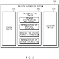
- FIG. 2 is a block diagram illustrating a configuration of an apparatus for controlling to enable an autonomous system in a vehicle in some forms of the present invention.
- a driving automation system 200 in some forms of the present invention may include a sensor device 210, a determination device 220, and an actuator device 230.
- the sensor device 210 may recognize a driving environment.
- the sensor device 210 may include a sensor (e.g., a radar, a light detection and ranging (LiDAR), a camera, and the like) which recognizes an environment around the vehicle and a vehicle sensor (e.g., a wheel speed sensor, a yaw rate sensor, and the like) which measures a state inside the vehicle.
- a sensor e.g., a radar, a light detection and ranging (LiDAR), a camera, and the like
- LiDAR light detection and ranging
- the sensor device 210 may include a detailed map or the like for performing a search for a destination and accurate position estimation.
- the determination device 220 may calculate various determination and control command values for operating the driving automation system 200.
- the determination device 220 may be, for example, an ECU.
- the determination device 220 may perform driving determination and control, determination of a critical situation, a warning for control authority transition, determination of driver intervention, and the like.
- the determination device 220 may determine a critical situation incapable of being avoided, based on the recognized situation around the vehicle and the calculated control command value.
- the determination device 220 may determine a stage of the warning for control authority transition.
- the warning may include a first-stage warning and a second-stage warning.
- the warning may be configured to be sensuously recognizable by the driver.
- the determination device 220 may recognize driver intervention and may determine whether to release the driving automation system 200.
- the actuator device 230 may control a behavior of the vehicle.
- the actuator device 230 may include an ECU for motor control, capable of automatically controlling a steering wheel of the vehicle, and an ECU for motor control, capable of automatically controlling a throttle and a brake of the vehicle.
- the actuator device 230 may include an actuator for controlling the steering wheel, the throttle, and the brake.
- FIG. 3 is a drawing illustrating an exemplary operation of an apparatus for controlling to enable an autonomous system in a vehicle in some forms of the present invention.
- a vehicle 310 may perform autonomous control. While the autonomous control is performed, the vehicle 310 may detect a first type of critical situation.
- the first type of critical situation may be a situation with relatively low risk.
- the vehicle 310 may output a notification (a first-stage notification) for handing over control authority to its driver.
- a notification a first-stage notification
- the vehicle 310 may determine that driver intervention is detected.
- the vehicle 310 may temporarily release the autonomous control. Subsequently, when the critical situation is released, the vehicle 310 may automatically re-enable the autonomous control.
- a vehicle 320 in some forms of the present invention may perform autonomous control. While the autonomous control is performed, the vehicle 320 may detect a second type of critical situation.
- the second type of critical situation may be a situation with relatively high risk.
- the vehicle 320 may output a notification (a second-stage notification) for handing over control authority to its driver.
- a notification a second-stage notification
- the vehicle 320 may determine that driver intervention is detected.
- the vehicle may release the autonomous control.
- the second-stage notification is output, although the critical situation is released at a later time, the vehicle 320 may maintain the state where the autonomous control is released. In this case, the autonomous control may be reenabled by only an input of the driver.
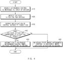
- FIG. 4 is a flowchart illustrating a method for controlling to enable an autonomous system in a vehicle in some forms of the present invention.
- a vehicle including an apparatus 100 for controlling to enable an autonomous system in FIG. 1 performs a process of FIG. 4 .
- an operation described as being performed by the vehicle may be understood as being controlled by a control circuit 140 of the apparatus 100 for controlling to enable the autonomous system.
- the vehicle may enable autonomous control in response to an input of its driver. For example, when an input of the driver to a button of the vehicle is received, the vehicle may initiate the autonomous control.
- the vehicle may detect a critical situation for the vehicle.
- the vehicle may detect the critical situation based on data generated by its sensor and information obtained from the inside of the vehicle.
- the vehicle may output a notification of control authority transition.
- the vehicle may output a sensuously sensible notification to hand over control authority to the driver.
- the vehicle may determine whether the critical situation corresponds to a critical situation of a specified type. For example, the vehicle may determine whether the critical situation corresponds to a specified situation with relative low risk.
- the vehicle may automatically re-enable the autonomous control when the critical situation is solved. For example, as control authority is handed over to the driver, after the autonomous control is released, when the critical situation is solved, the vehicle may automatically re-enable the autonomous control for convenience of the driver.
- the vehicle may maintain the state where the autonomous control is released, when the critical situation is solved. For example, as control authority is handed over to the driver, after the autonomous control is released, although the critical situation is solved, the vehicle may fail to enable the autonomous control for safety of the driver.
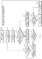
- FIG. 5 is a flowchart illustrating a method for controlling to enable an autonomous system in a vehicle in some forms of the present invention.
- a vehicle including an apparatus 100 for controlling to enable an autonomous system in FIG. 1 performs a process of FIG. 5 .
- an operation described as being performed by the vehicle may be understood as being controlled by a control circuit 140 of the apparatus 100 for controlling to enable the autonomous system.
- the vehicle may receive an input of its driver.
- the vehicle may receive an input of the driver to a button for enabling a driving automation system.
- the vehicle may enable an autonomous system.
- the autonomous system may be enabled in consideration of an enabling condition of a system (e.g., in case of a system available on a limited-access road, when the vehicle travels on the limited-access road).
- the vehicle may determine a critical situation.
- the vehicle may detect a situation incapable of being controlled by the autonomous system.
- the vehicle may determine whether the detected critical situation corresponds to a critical situation of a specified type.
- the vehicle may output a first-stage notification of control authority transition.
- the vehicle may detect driver intervention.
- the vehicle may temporarily release the autonomous system.
- the vehicle may determine whether the critical situation is solved. When the critical situation is solved, the vehicle may return to operation 510 to automatically enable the autonomous system.
- the vehicle may output a second-stage notification of control authority transition.
- the vehicle may detect driver intervention.
- the vehicle may execute an MRM.
- the vehicle may release the autonomous system. After operation 560, the vehicle may fail to automatically enable the autonomous system, and may enable the autonomous system only when an input of the driver to a button of the vehicle or the like is received.
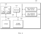
- FIG. 6 is a block diagram illustrating a configuration of a computing system in some forms of the present invention.
- a computing system 1000 may include at least one processor 1100, a memory 1300, a user interface input device 1400, a user interface output device 1500, a storage 1600, and a network interface 1700, which are connected with each other via a bus 1200.
- the processor 1100 may be a central processing unit (CPU) or a semiconductor device for performing processing of instructions stored in the memory 1300 and/or the storage 1600.
- CPU central processing unit
- Each of the memory 1300 and the storage 1600 may include various types of volatile or non-volatile storage media.
- the memory 1300 may include a read only memory (ROM) and a random access memory (RAM).
- the operations of the methods or algorithms described in some forms of the present invention disclosed in the specification may be directly implemented with a hardware module, a software module, or combinations thereof, executed by the processor 1100.
- the software module may reside on a storage medium (i.e., the memory 1300 and/or the storage 1600) such as a RAM, a flash memory, a ROM, an erasable and programmable ROM (EPROM), an electrically EPROM (EEPROM), a register, a hard disc, a removable disc, or a compact disc-ROM (CD-ROM).
- An exemplary storage medium may be coupled to the processor 1100.
- the processor 1100 may read out information from the storage medium and may write information in the storage medium.
- the storage medium may be integrated with the processor 1100.
- the processor and storage medium may reside in an application specific integrated circuit (ASIC).
- the ASIC may reside in a user terminal.
- the processor and storage medium may reside as a separate component of the user terminal.
- the apparatus and method in some forms of the present invention may reduce inconvenience of the driver due to the release of the autonomous system and may decrease risk due to automatically enabling the system by automatically re-enabling autonomous control in consideration of a type of a critical situation.
Description
- The present application claims priority to and the benefit of
Korean Patent Application No. 10-2018-0163249, filed on December 17, 2018 US Patent Application No. 62/655,831, filed on April 11, 2018 - The present invention relates to an apparatus and method for controlling to enable an autonomous system included in an autonomous vehicle.
- The statements in this section merely provide background information related to the present invention and may not constitute prior art.
- With the development of the auto industry, an autonomous system and a driving assistance system which facilitates partially autonomous driving (hereinafter, for convenience of description, both of autonomous driving and driving assistance are referred to as "autonomous driving") have been developed. The autonomous system may provide a variety of functions, for example, setting speed keeping, vehicle-to-vehicle distance keeping, lane keeping, and a lane change. The autonomous system may perform autonomous driving using various devices such as a sensor for sensing environments outside the vehicle, a sensor for sensing information about the vehicle, a global positioning system (GPS), a detailed map, a driver state monitoring system, a steering actuator, an acceleration/deceleration actuator, a communication circuit, and a control circuit (e.g., an electronic control unit (ECU)). The autonomous system may be enabled according to an input of a driver. When a problem occurs or when the occurrence of the problem is predicted, the autonomous system may provide a notification of control authority transition to the driver. When the driver takes over control authority, the autonomous system may be released.
- When the autonomous system is released due to the occurrence of a critical situation, after the critical situation is solved, the driver should provide an input for enabling the autonomous system again. There are various critical situations during autonomous driving. Whenever a critical situation occurs, after the autonomous system is released, when the vehicle requests the driver to provide an input for re-enabling the autonomous system, the driver may suffer from inconveniences. However, when the vehicle randomly enables the autonomous system without the input of the driver, the autonomous system may be enabled against the will of the driver.
EP 3 264 211 A1 relates to a method for use by a driving assistance apparatus that assists a transition from an autonomous driving mode in which a vehicle is driven under autonomous control to a manual driving mode in which the vehicle is driven by a driver.
US 2016/187879 A1 relates to an autonomous vehicle interface for a vehicle and a method of enabling and employing an autonomous vehicle interface for a vehicle. The autonomous vehicle interface may be configured to seamlessly transition driving modes or the vehicle's mode of operation from user controlled to an autonomous controlled driving without the user physically activating the autonomous controlled driving. - An aspect of the present invention provides an apparatus and method for selectively restarting an autonomous system when a critical situation is solved after the autonomous system is released due to the critical situation.
- The technical problems to be solved by the present inventive concept are not limited to the aforementioned problems, and any other technical problems not mentioned herein will be clearly understood from the following description by those skilled in the art to which the present invention pertains.
- In one aspect of the present invention, an apparatus for controlling to enable an autonomous system in a vehicle includes: a sensor configured to sense information about the outside and inside of the vehicle, an input device configured to receive an input from a driver of the vehicle, an output device configured to output a notification in the vehicle, and a control circuit configured to be electrically connected with the sensor, the input device, and the output device. The control circuit is configured to enable autonomous control in response to an input of the driver to the input device, detect a critical situation for the vehicle using the sensor, output a notification of control authority transition using the output device in response to the detecting of the critical situation, and automatically re-enable the autonomous control when the critical situation is solved after temporarily releasing the autonomous control, when the critical situation corresponds to a critical situation of a specified type.
- In some form of the present invention, the control circuit may be configured to output a fist type of notification using the output device, when the critical situation corresponds to the critical situation of the specified type and output a second type of notification using the output device, when the critical situation does not correspond to the critical situation of the specified type.
- In some form of the present invention, critical situation of the specified type may include at least a portion of prediction of temporary departure from an operational design domain (ODD) of the autonomous control, detection of driver distraction, detection of steering control of less than or equal to a specified level by the driver, or detection of acceleration control of less than or equal to a specified level by the driver.
- In some form of the present invention, the control circuit may be configured to predict the temporary departure based on traveling route information and map information.
- In some form of the present invention, the control circuit may be configured to detect the driver distraction by monitoring whether the driver looks ahead of the vehicle using the sensor.
- In some form of the present invention, the control circuit may be configured to detect the steering control by monitoring movement of a steering wheel included in the vehicle.
- In some form of the present invention, the control circuit may be configured to detect the acceleration control by monitoring movement of an accelerator pedal included in the vehicle.
- In some form of the present invention, the control circuit may be configured to temporarily release the autonomous control, when the critical situation corresponds to the critical situation of the specified type and when control authority is handed over to the driver.
- In some form of the present invention, the control circuit may be configured to output a first type of notification in response to the detecting of the critical situation, when the critical situation corresponds to the critical situation of the specified type and output a second type of notification, when control authority is not handed over to the driver during a specified time after the first type of notification is output.
- In some form of the present invention, the control circuit may be configured to release the autonomous control, when the critical situation does not correspond to the critical situation of the specified type, maintain the state where the autonomous control is released, when the critical situation is solved, and re-enable the autonomous control only when an input of the driver to the input device is detected again.
- In some form of the present invention, the control circuit may be configured to release the autonomous control, when the critical situation does not correspond to the critical situation of the specified type and when control authority is handed over to the driver.
- In some form of the present invention, the control circuit may be configured to control the vehicle according to a predetermined minimum risk maneuver (MRM), when control authority is not handed over to the driver during a specified time after the notification of the control authority transition is output.
- In some form of the present invention, a method for controlling to enable an autonomous system in a vehicle includes: enabling autonomous control in response to an input of a driver of the vehicle to an input device included in the vehicle, detecting a critical situation for the vehicle, outputting a notification of control authority transition in the vehicle in response to the detecting of the critical situation, and automatically re-enabling the autonomous control when the critical situation is solved after temporarily releasing the autonomous control, when the critical situation corresponds to a critical situation of a specified type.
- In some form of the present invention, the re-enabling may include temporarily releasing the autonomous control, when the critical situation corresponds to the critical situation of the specified type and when control authority is handed over to the driver.
- In some form of the present invention, the method may further include releasing the autonomous control, when the critical situation does not correspond to the critical situation of the specified type, maintaining the state where the autonomous control is released, when the critical situation is solved, and re-enabling the autonomous control only when an input of the driver to the input device is detected again.
- Further areas of applicability will become apparent from the description provided herein. It should be understood that the description and specific examples are intended for purposes of illustration only and are not intended to limit the scope of the present invention as defined by the appended claims.
- In order that the invention may be well understood, there will now be described various forms thereof, given by way of example, reference being made to the accompanying drawings, in which:
-
FIG. 1 is a block diagram illustrating a configuration of an apparatus for controlling to enable an autonomous system in a vehicle in one form of the present invention; -
FIG. 2 is a block diagram illustrating a configuration of an apparatus for controlling to enable an autonomous system in a vehicle in one form of the present invention; -
FIG. 3 is a drawing illustrating an exemplary operation of an apparatus for controlling to enable an autonomous system in a vehicle in one form of the present invention; -
FIG. 4 is a flowchart illustrating a method for controlling to enable an autonomous system in a vehicle in one form of the present invention; -
FIG. 5 is a flowchart illustrating a method for controlling to enable an autonomous system in a vehicle in one form of the present invention; and -
FIG. 6 is a block diagram illustrating a configuration of a computing system in one form of the present invention. - The drawings described herein are for illustration purposes only and are not intended to limit the scope of the present invention in any way.
- The following description is merely exemplary in nature and is not intended to limit the present invention, application, or uses. It should be understood that throughout the drawings, corresponding reference numerals indicate like or corresponding parts and features.
- In describing elements of forms of the present invention, the terms 1st, 2nd, first, second, A, B, (a), (b), and the like may be used herein. These terms are only used to distinguish one element from another element, but do not limit the corresponding elements irrespective of the nature, turn, or order of the corresponding elements. Unless otherwise defined, all terms used herein, including technical or scientific terms, have the same meanings as those generally understood by those skilled in the art to which the present invention pertains. Such terms as those defined in a generally used dictionary are to be interpreted as having meanings equal to the contextual meanings in the relevant field of art, and are not to be interpreted as having ideal or excessively formal meanings unless clearly defined as having such in the present application.
-
FIG. 1 is a block diagram illustrating a configuration of an apparatus for controlling to enable an autonomous system in a vehicle in some forms of the present invention. - Referring to
FIG. 1 , anapparatus 100 for controlling to enable an autonomous system in a vehicle in some forms of the present invention includes asensor 110, aninput device 120, an output device, and acontrol circuit 140. Theapparatus 100 for controlling to enable the autonomous system inFIG. 1 may be a portion of the autonomous system and may be loaded into the vehicle. - The
sensor 110 is configured to sense information about the outside and inside of the vehicle. For example, thesensor 110 may include a radar, a light detection and ranging (LiDAR), a camera, and the like for sensing an environment outside the vehicle, and may include a wheel speed sensor, a yaw rate sensor, an acceleration sensor, a torque sensor, and the like, which sense a state of the vehicle. - The
input device 120 is configured to receive an input from a driver of the vehicle. For example, theinput device 120 may be implemented as a button, a switch, a lever, a touch sensor, or the like. - The
output device 130 is configured to output a notification in the vehicle. For example, theoutput device 130 may be implemented in a form, such as a speaker, a haptic module, and a display, which is capable of outputting a notification sensuously recognizable by the driver. - The
control circuit 140 is electrically connected with thesensor 110, theinput device 120, and theoutput device 130. Thecontrol circuit 140 may control thesensor 110, theinput device 120, and theoutput device 130 and may perform a variety of data processing and various arithmetic operations. Thecontrol circuit 140 may be, for example, an electronic control unit (ECU), a micro controller unit (MCU), or a sub-controller, which is loaded into the vehicle. - According to the present invention, the
control circuit 140 enables autonomous control in response to an input of the driver to theinput device 120. When the driver provides an input to theinput device 120 to enable the autonomous control, thecontrol circuit 140 initiates the autonomous control. - In some forms of the present invention, the
control circuit 140 detects a critical situation for the vehicle using thesensor 110. The critical situation may include situations, for example, departure from an operational design domain (ODD) of the autonomous control, driver distraction, steering control by the driver, acceleration control by the driver, deceleration control by the driver, collision risk detection, a system failure, and the like. - According to the present invention, the
control circuit 140 outputs a notification of control authority transition using theoutput device 130 in response to the detecting of the critical situation. Thecontrol circuit 140 outputs a notification to hand over control authority to the driver in response to the critical situation. In some forms of the present invention, when the critical situation corresponds to a critical situation of a specified type, thecontrol circuit 140 may output a first type of notification using theoutput device 130. When the critical situation does not correspond to the critical situation of the specified type, thecontrol circuit 140 may output a second type of notification using theoutput device 130. The critical situation of the specified type may be a situation with relatively low risk, and a critical situation of a type except for the specified type may be a situation with relatively high risk. - In some forms of the present invention, the
control circuit 140 may determine whether the critical situation corresponds to the critical situation of the specified type. For example, the critical situation of the specified type may include at least a portion of prediction (e.g., a tollgate) of temporary departure from the ODD of the autonomous control, detection of driver distraction, detection of steering control of less than or equal to a specified level by the driver, or detection of acceleration control of less than or equal to a specified level by the driver. For example, thecontrol circuit 140 may predict the temporary departure based on information about a route where the vehicle is traveling and map information. For another example, thecontrol circuit 140 may detect the driver distraction by monitoring whether the driver looks ahead of the vehicle using thesensor 110. For another example, thecontrol circuit 140 may detect the steering control by monitoring movement of a steering wheel included in the vehicle. For another example, thecontrol circuit 140 may detect the acceleration control by monitoring movement of an accelerator pedal included in the vehicle. The critical situation of the type except for the specified type may be another critical situation except for the critical situation of the specified type. For example, the critical situation of the type except for the specified type may include when control authority is not handed over to the driver in response to a first-stage notification, when departure from the ODD of the autonomous control is predicted (e.g., when the vehicle enters a normal road), when drowsiness of the driver is detected, when steering control of greater than or equal to a specified level is performed by the driver, when acceleration control of greater than or equal to a specified level is performed by the driver, when deceleration control is performed by the driver, when accident (e.g., collision) risk is detected, when a system failure is detected, and the like. - According to the present invention, when the critical situation corresponds to the critical situation of the specified type, the
control circuit 140 temporarily releases the autonomous control and automatically re-enables the autonomous control when the critical situation is solved. In detail, when the critical situation corresponds to the critical situation of the specified type, thecontrol circuit 140 may output the first type of notification in response to the detecting of the critical situation. When control authority is handed over to the driver while the notification is output, thecontrol circuit 140 temporarily releases the autonomous control. After the autonomous control is released, when the critical situation is solved, thecontrol circuit 140 automatically re-enables the autonomous control. Thus, in a situation with relatively low risk, the autonomous control may be automatically enabled without an input of the driver. - In some forms of the present invention, when control authority is not handed over to the driver during a specified time after the first type of notification is output, the
control circuit 140 may output a second type of notification. When outputting the second type of notification, thecontrol circuit 140 may proceed with a subsequent process to be the same as when the critical situation does not correspond to the critical situation of the specified type. - In some forms of the present invention, when the critical situation does not correspond to the critical situation of the specified type, the
control circuit 140 may release the autonomous control and may maintain the state where the autonomous control is released when the critical situation is solved, thus re-enabling the autonomous control only when an input of the driver to theinput device 120 is detected again. In detail, when the critical situation does not correspond to the critical situation of the specified type, thecontrol circuit 140 may output the second type of notification. When control authority is handed over to the driver while the notification is output, thecontrol circuit 140 may release the autonomous control. After the autonomous control is released, although the critical situation is solved, thecontrol circuit 140 may maintain the state where the autonomous control is released, without enabling the autonomous control. Only when the driver requests the vehicle to enable the autonomous control depending on the will of the driver, thecontrol circuit 140 may re-enable the autonomous control. - In some forms of the present invention, when the critical situation does not correspond to the critical situation of the specified type and when control authority is not handed over to the driver during a specified time after the notification of control authority is output, the
control circuit 140 may control the vehicle according to a predetermined MRM. -
FIG. 2 is a block diagram illustrating a configuration of an apparatus for controlling to enable an autonomous system in a vehicle in some forms of the present invention. - Referring to
FIG. 2 , adriving automation system 200 in some forms of the present invention may include asensor device 210, adetermination device 220, and anactuator device 230. - The
sensor device 210 may recognize a driving environment. For example, thesensor device 210 may include a sensor (e.g., a radar, a light detection and ranging (LiDAR), a camera, and the like) which recognizes an environment around the vehicle and a vehicle sensor (e.g., a wheel speed sensor, a yaw rate sensor, and the like) which measures a state inside the vehicle. Thesensor device 210 may include a detailed map or the like for performing a search for a destination and accurate position estimation. - The
determination device 220 may calculate various determination and control command values for operating thedriving automation system 200. Thedetermination device 220 may be, for example, an ECU. Thedetermination device 220 may perform driving determination and control, determination of a critical situation, a warning for control authority transition, determination of driver intervention, and the like. For example, thedetermination device 220 may determine a critical situation incapable of being avoided, based on the recognized situation around the vehicle and the calculated control command value. For another example, thedetermination device 220 may determine a stage of the warning for control authority transition. The warning may include a first-stage warning and a second-stage warning. The warning may be configured to be sensuously recognizable by the driver. For another example, thedetermination device 220 may recognize driver intervention and may determine whether to release thedriving automation system 200. - The
actuator device 230 may control a behavior of the vehicle. Theactuator device 230 may include an ECU for motor control, capable of automatically controlling a steering wheel of the vehicle, and an ECU for motor control, capable of automatically controlling a throttle and a brake of the vehicle. Theactuator device 230 may include an actuator for controlling the steering wheel, the throttle, and the brake. -
FIG. 3 is a drawing illustrating an exemplary operation of an apparatus for controlling to enable an autonomous system in a vehicle in some forms of the present invention. - Referring to
FIG. 3 , avehicle 310 according to an form may perform autonomous control. While the autonomous control is performed, thevehicle 310 may detect a first type of critical situation. The first type of critical situation may be a situation with relatively low risk. Thevehicle 310 may output a notification (a first-stage notification) for handing over control authority to its driver. When a steering input, an accelerator pedal input, and a decelerator pedal input occur, thevehicle 310 may determine that driver intervention is detected. When the driver intervention is detected, thevehicle 310 may temporarily release the autonomous control. Subsequently, when the critical situation is released, thevehicle 310 may automatically re-enable the autonomous control. - A
vehicle 320 in some forms of the present invention may perform autonomous control. While the autonomous control is performed, thevehicle 320 may detect a second type of critical situation. The second type of critical situation may be a situation with relatively high risk. Thevehicle 320 may output a notification (a second-stage notification) for handing over control authority to its driver. When a steering input, an accelerator input, and a decelerator input occur, thevehicle 320 may determine that driver intervention is detected. When the driver intervention is detected, the vehicle may release the autonomous control. When the second-stage notification is output, although the critical situation is released at a later time, thevehicle 320 may maintain the state where the autonomous control is released. In this case, the autonomous control may be reenabled by only an input of the driver. -
FIG. 4 is a flowchart illustrating a method for controlling to enable an autonomous system in a vehicle in some forms of the present invention. - Hereinafter, it is assumed that a vehicle including an
apparatus 100 for controlling to enable an autonomous system inFIG. 1 performs a process ofFIG. 4 . Furthermore, in a description ofFIG. 4 , an operation described as being performed by the vehicle may be understood as being controlled by acontrol circuit 140 of theapparatus 100 for controlling to enable the autonomous system. - Referring to
FIG. 4 , inoperation 410, the vehicle may enable autonomous control in response to an input of its driver. For example, when an input of the driver to a button of the vehicle is received, the vehicle may initiate the autonomous control. - In
operation 420, the vehicle may detect a critical situation for the vehicle. For example, the vehicle may detect the critical situation based on data generated by its sensor and information obtained from the inside of the vehicle. - In
operation 430, the vehicle may output a notification of control authority transition. For example, the vehicle may output a sensuously sensible notification to hand over control authority to the driver. - In
operation 440, the vehicle may determine whether the critical situation corresponds to a critical situation of a specified type. For example, the vehicle may determine whether the critical situation corresponds to a specified situation with relative low risk. - When the critical situation corresponds to the critical situation of the specified type, in
operation 450, the vehicle may automatically re-enable the autonomous control when the critical situation is solved. For example, as control authority is handed over to the driver, after the autonomous control is released, when the critical situation is solved, the vehicle may automatically re-enable the autonomous control for convenience of the driver. - When the critical situation does not correspond to the critical situation of the specified type, in
operation 460, the vehicle may maintain the state where the autonomous control is released, when the critical situation is solved. For example, as control authority is handed over to the driver, after the autonomous control is released, although the critical situation is solved, the vehicle may fail to enable the autonomous control for safety of the driver. -
FIG. 5 is a flowchart illustrating a method for controlling to enable an autonomous system in a vehicle in some forms of the present invention. - Hereinafter, it is assumed that a vehicle including an
apparatus 100 for controlling to enable an autonomous system inFIG. 1 performs a process ofFIG. 5 . Furthermore, in a description ofFIG. 5 , an operation described as being performed by the vehicle may be understood as being controlled by acontrol circuit 140 of theapparatus 100 for controlling to enable the autonomous system. - Referring to
FIG. 5 , inoperation 505, the vehicle may receive an input of its driver. For example, the vehicle may receive an input of the driver to a button for enabling a driving automation system. Inoperation 510, the vehicle may enable an autonomous system. The autonomous system may be enabled in consideration of an enabling condition of a system (e.g., in case of a system available on a limited-access road, when the vehicle travels on the limited-access road). Inoperation 515, the vehicle may determine a critical situation. The vehicle may detect a situation incapable of being controlled by the autonomous system. Inoperation 520, the vehicle may determine whether the detected critical situation corresponds to a critical situation of a specified type. - When the detected critical situation corresponds to the critical situation of the specified type, in
operation 525, the vehicle may output a first-stage notification of control authority transition. Inoperation 530, the vehicle may detect driver intervention. When the driver intervention is detected, inoperation 535, the vehicle may temporarily release the autonomous system. Inoperation 540, the vehicle may determine whether the critical situation is solved. When the critical situation is solved, the vehicle may return tooperation 510 to automatically enable the autonomous system. - When the detected critical situation does not correspond to the critical situation of the specified type or when there is no driver intervention after the first-stage notification occurs, in
operation 545, the vehicle may output a second-stage notification of control authority transition. Inoperation 550, the vehicle may detect driver intervention. When the driver intervention is not detected, inoperation 555, the vehicle may execute an MRM. When the driver intervention is detected, inoperation 560, the vehicle may release the autonomous system. Afteroperation 560, the vehicle may fail to automatically enable the autonomous system, and may enable the autonomous system only when an input of the driver to a button of the vehicle or the like is received. -
FIG. 6 is a block diagram illustrating a configuration of a computing system in some forms of the present invention. - Referring to
FIG. 6 , acomputing system 1000 may include at least oneprocessor 1100, amemory 1300, a userinterface input device 1400, a userinterface output device 1500, astorage 1600, and anetwork interface 1700, which are connected with each other via abus 1200. - The
processor 1100 may be a central processing unit (CPU) or a semiconductor device for performing processing of instructions stored in thememory 1300 and/or thestorage 1600. Each of thememory 1300 and thestorage 1600 may include various types of volatile or non-volatile storage media. For example, thememory 1300 may include a read only memory (ROM) and a random access memory (RAM). - Thus, the operations of the methods or algorithms described in some forms of the present invention disclosed in the specification may be directly implemented with a hardware module, a software module, or combinations thereof, executed by the
processor 1100. The software module may reside on a storage medium (i.e., thememory 1300 and/or the storage 1600) such as a RAM, a flash memory, a ROM, an erasable and programmable ROM (EPROM), an electrically EPROM (EEPROM), a register, a hard disc, a removable disc, or a compact disc-ROM (CD-ROM). An exemplary storage medium may be coupled to theprocessor 1100. Theprocessor 1100 may read out information from the storage medium and may write information in the storage medium. Alternatively, the storage medium may be integrated with theprocessor 1100. The processor and storage medium may reside in an application specific integrated circuit (ASIC). The ASIC may reside in a user terminal. Alternatively, the processor and storage medium may reside as a separate component of the user terminal. - The apparatus and method in some forms of the present invention may reduce inconvenience of the driver due to the release of the autonomous system and may decrease risk due to automatically enabling the system by automatically re-enabling autonomous control in consideration of a type of a critical situation.
- In addition, various effects directly or indirectly ascertained through the present invention may be provided.
- The description of the invention is merely exemplary in nature and, thus, variations that do not depart from the substance of the invention as defined by the appended claims are intended to be within the scope of the invention.
Claims (15)
- An apparatus (100) for controlling to enable an autonomous system in a vehicle, the apparatus (100) comprising:a sensor (110) configured to sense information regarding an outside of the vehicle and an inside of the vehicle;an input device (120) configured to receive an input from a driver of the vehicle;an output device (130) configured to output a notification in the vehicle; anda control circuit (140) configured to be electrically connected with the sensor (110), the input device (120), and the output device (130),wherein the control circuit (140) is configured to:activate an autonomous control in response to the received input;detect a critical situation of the vehicle by the sensor (110);output a notification to transfer a control authority by the output device (130) in response to the detected critical situation; and is characterised in that itautomatically reactivates the autonomous control when the critical situation is solved after temporarily releasing the autonomous control, wherein the critical situation corresponds to a critical situation of a specified type.
- The apparatus (100) of claim 1, wherein the control circuit (140) is configured to:output a fist type of notification by the output device (130) when the critical situation corresponds to the critical situation of the specified type; andoutput a second type of notification by the output device (130) when the critical situation does not correspond to the critical situation of the specified type.
- The apparatus (100) of claim 1 or 2, wherein the critical situation of the specified type comprises at least one of:prediction of temporary departure from an operational design domain, ODD, of the autonomous control;detection of driver distraction;detection of steering control by the driver for less than or equal to a specified level; ordetection of acceleration control by the driver for less than or equal to the specified level.
- The apparatus (100) of claim 3, wherein the control circuit (140) is configured to:
predict the temporary departure based on traveling route information and map information. - The apparatus (100) of claim 3, wherein the control circuit (140) is configured to:
detect the driver distraction by monitoring whether the driver looks ahead of the vehicle using the sensor (110). - The apparatus (100) of claim 3, wherein the control circuit (140) is configured to:
detect the steering control by monitoring a movement of a steering wheel. - The apparatus (100) of claim 3, wherein the control circuit (140) is configured to:
detect the acceleration control by monitoring a movement of an accelerator pedal. - The apparatus (100) of one of claims 1 to 7, wherein the control circuit (140) is configured to:
temporarily release the autonomous control, when the critical situation corresponds to the critical situation of the specified type and when the control authority is transferred to the driver. - The apparatus (100) of one of claims 1 to 8, wherein the control circuit (140) is configured to:output a first type of notification in response to the detected critical situation when the critical situation corresponds to the critical situation of the specified type; andoutput a second type of notification when the control authority is not transferred to the driver for a predetermined amount of time after outputting the first type of notification.
- The apparatus (100) of one of claims 1 to 9, wherein the control circuit (140) is configured to:release the autonomous control when the critical situation does not correspond to the critical situation of the specified type;maintain releasing the autonomous control when the critical situation is solved; andreactivate the autonomous control only when the input is detected again.
- The apparatus (100) of claim 10, wherein the control circuit (140) is configured to:
release the autonomous control when the critical situation does not correspond to the critical situation of the specified type and when the control authority is transferred to the driver. - The apparatus (100) of claim 10, wherein the control circuit (140) is configured to:
control the vehicle based on a predetermined minimum risk maneuver (MRM) when the control authority is not transferred to the driver for the predetermined amount of time after outputting the notification to transfer the control authority. - A method for controlling to enable an autonomous system in a vehicle, the method comprising:activating, with a control circuit (140) included in the vehicle, an autonomous control in response to an input of a driver of the vehicle to an input device (120) included in the vehicle;detecting, with a sensor (110) included in the vehicle, a critical situation of the vehicle;outputting, with an output device (130) included in the vehicle, a notification to transfer a control authority in the vehicle in response to the detected critical situation;characterised inautomatically reactivating, with the control circuit (140), the autonomous control when the critical situation is solved after temporarily releasing the autonomous control, wherein the critical situation corresponds to a critical situation of a specified type.
- The method of claim 13, wherein reactivating the autonomous control further comprises:
when the critical situation corresponds to the critical situation of the specified type and when the control authority is transferred to the driver, temporarily releasing, with the control circuit (140), the autonomous control. - The method of claim 13 or 14, wherein the method further comprises:when the critical situation does not correspond to the critical situation of the specified type, releasing, with the control circuit (140), the autonomous control;when the critical situation is solved, maintaining, with the control circuit (140), releasing the autonomous control; andreactivating, with the control circuit (140), the autonomous control only when the input of the driver is detected again.
Applications Claiming Priority (2)
| Application Number | Priority Date | Filing Date | Title |
|---|---|---|---|
| US201862655831P | 2018-04-11 | 2018-04-11 | |
| KR1020180163249A KR20190124122A (en) | 2018-04-11 | 2018-12-17 | Apparatus and method for controlling activation of autonomous driving system of vehicle |
Publications (3)
| Publication Number | Publication Date |
|---|---|
| EP3552913A2 EP3552913A2 (en) | 2019-10-16 |
| EP3552913A3 EP3552913A3 (en) | 2020-06-10 |
| EP3552913B1 true EP3552913B1 (en) | 2021-08-18 |
Family
ID=66092154
Family Applications (1)
| Application Number | Title | Priority Date | Filing Date |
|---|---|---|---|
| EP19167265.8A Active EP3552913B1 (en) | 2018-04-11 | 2019-04-04 | Apparatus and method for controlling to enable autonomous system in vehicle |
Country Status (4)
| Country | Link |
|---|---|
| US (1) | US11550317B2 (en) |
| EP (1) | EP3552913B1 (en) |
| CN (1) | CN110371138A (en) |
| ES (1) | ES2889930T3 (en) |
Families Citing this family (16)
| Publication number | Priority date | Publication date | Assignee | Title |
|---|---|---|---|---|
| US11597403B2 (en) | 2018-04-11 | 2023-03-07 | Hyundai Motor Company | Apparatus for displaying driving state of vehicle, system including the same and method thereof |
| EP3552902A1 (en) | 2018-04-11 | 2019-10-16 | Hyundai Motor Company | Apparatus and method for providing a driving path to a vehicle |
| US11084490B2 (en) | 2018-04-11 | 2021-08-10 | Hyundai Motor Company | Apparatus and method for controlling drive of vehicle |
| US11077854B2 (en) | 2018-04-11 | 2021-08-03 | Hyundai Motor Company | Apparatus for controlling lane change of vehicle, system having the same and method thereof |
| ES2889930T3 (en) | 2018-04-11 | 2022-01-14 | Hyundai Motor Co Ltd | Apparatus and method for control to enable an autonomous system in a vehicle |
| US11084491B2 (en) | 2018-04-11 | 2021-08-10 | Hyundai Motor Company | Apparatus and method for providing safety strategy in vehicle |
| US10843710B2 (en) | 2018-04-11 | 2020-11-24 | Hyundai Motor Company | Apparatus and method for providing notification of control authority transition in vehicle |
| US11351989B2 (en) | 2018-04-11 | 2022-06-07 | Hyundai Motor Company | Vehicle driving controller, system including the same, and method thereof |
| EP3552901A3 (en) | 2018-04-11 | 2020-04-29 | Hyundai Motor Company | Apparatus and method for providing safety strategy in vehicle |
| US11173910B2 (en) | 2018-04-11 | 2021-11-16 | Hyundai Motor Company | Lane change controller for vehicle system including the same, and method thereof |
| US11334067B2 (en) | 2018-04-11 | 2022-05-17 | Hyundai Motor Company | Apparatus and method for providing safety strategy in vehicle |
| US11548509B2 (en) | 2018-04-11 | 2023-01-10 | Hyundai Motor Company | Apparatus and method for controlling lane change in vehicle |
| EP3569460B1 (en) | 2018-04-11 | 2024-03-20 | Hyundai Motor Company | Apparatus and method for controlling driving in vehicle |
| US10836394B2 (en) | 2018-04-11 | 2020-11-17 | Hyundai Motor Company | Apparatus and method for lane change control |
| JP7233537B2 (en) * | 2019-07-05 | 2023-03-06 | 三菱電機株式会社 | VEHICLE INFORMATION EQUIPMENT AND VEHICLE INFORMATION EQUIPMENT CONTROL METHOD |
| EP3838699A1 (en) | 2019-12-18 | 2021-06-23 | Hyundai Motor Company | Vehicle and method for controlling body thereof |
Family Cites Families (260)
| Publication number | Priority date | Publication date | Assignee | Title |
|---|---|---|---|---|
| US4361202A (en) | 1979-06-15 | 1982-11-30 | Michael Minovitch | Automated road transportation system |
| US5314037A (en) | 1993-01-22 | 1994-05-24 | Shaw David C H | Automobile collision avoidance system |
| DE4313568C1 (en) | 1993-04-26 | 1994-06-16 | Daimler Benz Ag | Guiding motor vehicle driver when changing traffic lanes - using radar devices to detect velocity and spacing of vehicles in next lane and indicate when lane changing is possible |
| DE19632929C1 (en) | 1996-08-16 | 1997-11-27 | Daimler Benz Ag | Automatic motor vehicle transverse guidance device |
| DE19821122A1 (en) | 1997-12-15 | 1999-06-17 | Volkswagen Ag | Procedure for controlling speed and distance in overtaking maneuvers |
| JP3824784B2 (en) | 1998-06-30 | 2006-09-20 | 富士通株式会社 | Driving support device, lane change permission determination device, method and recording medium |
| JP2000198458A (en) | 1999-01-08 | 2000-07-18 | Mazda Motor Corp | Control device of vehicle |
| JP3529037B2 (en) | 1999-08-02 | 2004-05-24 | 日産自動車株式会社 | Lane tracking device |
| DE10114187A1 (en) | 2001-03-23 | 2002-09-26 | Bosch Gmbh Robert | Overtaking maneuver assistance system for motor vehicle computes overtaking speed from distances of vehicle to be overtaken and immediately preceding vehicle in overtaking lane |
| JP2003025868A (en) | 2001-07-16 | 2003-01-29 | Nissan Motor Co Ltd | Lane-change supporting device for vehicle |
| DE10218010A1 (en) | 2002-04-23 | 2003-11-06 | Bosch Gmbh Robert | Method and device for lateral guidance support in motor vehicles |
| DE602004008541T2 (en) | 2003-07-07 | 2008-04-30 | Nissan Motor Co., Ltd., Yokohama | Control system for a vehicle for keeping the lane |
| CA2531662C (en) | 2003-07-07 | 2016-04-26 | Sensomatix Ltd. | Traffic information system |
| DE10350779A1 (en) | 2003-10-30 | 2005-06-02 | Robert Bosch Gmbh | Lane keeping system for a motor vehicle and operating method |
| JP4032253B2 (en) | 2003-12-17 | 2008-01-16 | ソニー株式会社 | Optical communication apparatus and vehicle control method |
| DE102004005815B3 (en) | 2004-02-06 | 2005-06-09 | Audi Ag | Automobile with selectively operated driver support systems and device for combined display of status of driver support systems via combined optical symbol |
| KR100578573B1 (en) | 2004-05-06 | 2006-05-12 | 기아자동차주식회사 | Limiting Speed indication and warning device |
| JP4379199B2 (en) | 2004-05-17 | 2009-12-09 | 日産自動車株式会社 | Lane change support apparatus and method |
| DE102004029369B4 (en) | 2004-06-17 | 2016-09-15 | Robert Bosch Gmbh | Lane change assistant for motor vehicles |
| DE102004048009A1 (en) | 2004-10-01 | 2006-04-06 | Robert Bosch Gmbh | Method and device for driver assistance |
| DE102004048468A1 (en) | 2004-10-05 | 2006-04-13 | Siemens Ag | System and method for setting the speed of a vehicle to a maximum permissible speed |
| EP1849669B1 (en) | 2006-04-28 | 2011-10-05 | Nissan Motor Co., Ltd. | Lane departure prevention apparatus and method for a motor vehicle |
| JP4582052B2 (en) | 2006-06-07 | 2010-11-17 | トヨタ自動車株式会社 | Driving support device |
| JP4449960B2 (en) | 2006-08-22 | 2010-04-14 | トヨタ自動車株式会社 | Steering support device |
| JP4525670B2 (en) | 2006-11-20 | 2010-08-18 | トヨタ自動車株式会社 | Travel control plan generation system |
| DE102007005245A1 (en) | 2007-02-02 | 2007-11-22 | Daimlerchrysler Ag | Method for operating a driver assistance system e.g. for motor vehicle, involves using display instrument to show relevant traffic information at given time point |
| JP4748122B2 (en) | 2007-06-28 | 2011-08-17 | 日産自動車株式会社 | Lane departure prevention device |
| JP4366419B2 (en) | 2007-09-27 | 2009-11-18 | 株式会社日立製作所 | Driving support device |
| EP2062796B1 (en) | 2007-11-20 | 2010-08-04 | Nissan Motor Co., Ltd. | Lane deviation prevention device and method |
| JP2009184554A (en) | 2008-02-07 | 2009-08-20 | Denso Corp | Safe travel assisting system |
| DE102008001677A1 (en) | 2008-05-09 | 2009-11-12 | Robert Bosch Gmbh | Assistance system for driver assistance in vehicles |
| US8392064B2 (en) | 2008-05-27 | 2013-03-05 | The Board Of Trustees Of The Leland Stanford Junior University | Systems, methods and devices for adaptive steering control of automotive vehicles |
| US8170739B2 (en) | 2008-06-20 | 2012-05-01 | GM Global Technology Operations LLC | Path generation algorithm for automated lane centering and lane changing control system |
| US9846049B2 (en) | 2008-07-09 | 2017-12-19 | Microsoft Technology Licensing, Llc | Route prediction |
| DE112010000085A5 (en) | 2009-02-03 | 2012-08-16 | Adc Automotive Distance Control Systems Gmbh | Speed preset for a vehicle with automatic longitudinal control |
| JP5523448B2 (en) | 2009-04-23 | 2014-06-18 | パナソニック株式会社 | Driving support system, information display device, and information display program |
| US8164543B2 (en) | 2009-05-18 | 2012-04-24 | GM Global Technology Operations LLC | Night vision on full windshield head-up display |
| KR101286377B1 (en) | 2009-12-09 | 2013-07-15 | 주식회사 만도 | Method and apparatus for contorlling transient state of lane change, and adaptive cruise control system using the same method |
| DE102010004625A1 (en) | 2010-01-14 | 2011-07-21 | Ford Global Technologies, LLC, Mich. | Method and device for assisting a driver in an overtaking process |
| US8384534B2 (en) | 2010-01-14 | 2013-02-26 | Toyota Motor Engineering & Manufacturing North America, Inc. | Combining driver and environment sensing for vehicular safety systems |
| WO2011111121A1 (en) | 2010-03-12 | 2011-09-15 | トヨタ自動車株式会社 | Steering support device |
| US8618922B2 (en) | 2010-03-30 | 2013-12-31 | GM Global Technology Operations LLC | Method and system for ensuring operation of limited-ability autonomous driving vehicles |
| JP2012051441A (en) * | 2010-08-31 | 2012-03-15 | Toyota Motor Corp | Automatic operation vehicle control device |
| DE102010049351A1 (en) | 2010-10-23 | 2012-04-26 | Daimler Ag | A method of operating a brake assist device and brake assist device for a vehicle |
| US8977419B2 (en) | 2010-12-23 | 2015-03-10 | GM Global Technology Operations LLC | Driving-based lane offset control for lane centering |
| WO2012131405A1 (en) | 2011-03-29 | 2012-10-04 | Josic Ante | Automatic control of maximum speed and automatic control system thereof |
| DE102011016771A1 (en) | 2011-04-12 | 2012-10-18 | Daimler Ag | Device for operating lane change assist in vehicle, has manual operating unit for driver-side activation of lane change, which is coupled to or integrated with direction sensor |
| DE102011016770B4 (en) | 2011-04-12 | 2021-02-04 | Daimler Ag | Method for assisting a driver of a vehicle when changing lanes and device for carrying out the method |
| JP2012226392A (en) | 2011-04-14 | 2012-11-15 | Honda Elesys Co Ltd | Drive support system |
| US8670903B2 (en) | 2011-05-05 | 2014-03-11 | GM Global Technology Operations LLC | Lane centering fail-safe control using differential braking |
| US8935071B2 (en) | 2011-05-05 | 2015-01-13 | GM Global Technology Operations LLC | Optimal fusion of electric park brake and hydraulic brake sub-system functions to control vehicle direction |
| EP2711908A4 (en) | 2011-05-20 | 2015-01-21 | Honda Motor Co Ltd | Lane change assistant system |
| DE102011109618A1 (en) | 2011-08-05 | 2013-02-07 | Daimler Ag | Method for operating vehicle, involves automatically determining driving impairment of driver while activating engagement to brake, steering or drive train function of vehicle, so that vehicle is decelerated to standstill |
| DE102011081892A1 (en) | 2011-08-31 | 2013-02-28 | Robert Bosch Gmbh | Method for lane monitoring and lane monitoring system for a vehicle |
| US8838325B2 (en) | 2011-09-12 | 2014-09-16 | Ford Global Technologies | Vehicle shut-down functionality for peps-equipped vehicles |
| DE102011086241B4 (en) | 2011-11-14 | 2018-04-05 | Robert Bosch Gmbh | Method for the safe parking of a vehicle |
| DE102012001405A1 (en) | 2012-01-26 | 2012-11-22 | Daimler Ag | Method for performing lane change of vehicle from current lane, involves determining whether lane change of vehicle is safely feasible along determined transition trajectory, based on movement of other road users |
| DE102012002304A1 (en) | 2012-02-06 | 2013-08-08 | Audi Ag | Apparatus for automated driving of a motor vehicle and method for operating a motor vehicle |
| JP5868218B2 (en) | 2012-02-28 | 2016-02-24 | 株式会社日本自動車部品総合研究所 | Vehicle control device |
| US8457827B1 (en) | 2012-03-15 | 2013-06-04 | Google Inc. | Modifying behavior of autonomous vehicle based on predicted behavior of other vehicles |
| JP5754544B2 (en) | 2012-03-22 | 2015-07-29 | トヨタ自動車株式会社 | Brake control device |
| US9315178B1 (en) | 2012-04-13 | 2016-04-19 | Google Inc. | Model checking for autonomous vehicles |
| DE102012008090A1 (en) | 2012-04-21 | 2013-10-24 | Volkswagen Aktiengesellschaft | Method and device for emergency stop of a motor vehicle |
| US8521352B1 (en) | 2012-05-07 | 2013-08-27 | Google Inc. | Controlling a vehicle having inadequate map data |
| KR101896720B1 (en) | 2012-12-24 | 2018-09-07 | 현대자동차주식회사 | Autonomous lane change control system |
| US8798841B1 (en) | 2013-03-14 | 2014-08-05 | GM Global Technology Operations LLC | System and method for improving sensor visibility of vehicle in autonomous driving mode |
| US9751534B2 (en) | 2013-03-15 | 2017-09-05 | Honda Motor Co., Ltd. | System and method for responding to driver state |
| GB2512317A (en) | 2013-03-26 | 2014-10-01 | Jaguar Land Rover Ltd | Vehicle control system and method |
| KR101439017B1 (en) | 2013-04-11 | 2014-10-30 | 현대자동차주식회사 | System for controlling change of lane |
| US20140309855A1 (en) | 2013-04-12 | 2014-10-16 | Bao Tran | Smart car with automatic signalling |
| US8874301B1 (en) | 2013-07-09 | 2014-10-28 | Ford Global Technologies, Llc | Autonomous vehicle with driver presence and physiological monitoring |
| US8930060B1 (en) | 2013-07-15 | 2015-01-06 | Ford Global Technologies | Post-impact path assist for vehicles |
| WO2015026352A1 (en) | 2013-08-22 | 2015-02-26 | Intel Corporation | Locality adapted computerized assisted or autonomous driving of vehicles |
| JP6337435B2 (en) | 2013-09-26 | 2018-06-06 | 日産自動車株式会社 | Driving assistance device |
| DE102013219887A1 (en) * | 2013-10-01 | 2015-04-02 | Volkswagen Aktiengesellschaft | Method for a driver assistance system of a vehicle |
| JP6257989B2 (en) | 2013-10-08 | 2018-01-10 | 日産自動車株式会社 | Driving assistance device |
| US9718473B2 (en) | 2013-10-11 | 2017-08-01 | Nissan Motor Co., Ltd. | Travel control device and travel control method |
| KR20150061752A (en) | 2013-11-28 | 2015-06-05 | 현대모비스 주식회사 | Device for driving assist and method for activating the function automatically by the device |
| US9988047B2 (en) | 2013-12-12 | 2018-06-05 | Magna Electronics Inc. | Vehicle control system with traffic driving control |
| DE102014200896A1 (en) | 2014-01-20 | 2015-07-23 | Volkswagen Aktiengesellschaft | Lane change assistance for a motor vehicle |
| JP6237256B2 (en) | 2014-01-21 | 2017-11-29 | 日産自動車株式会社 | Vehicle speed control device |
| KR20150087619A (en) | 2014-01-22 | 2015-07-30 | 한국전자통신연구원 | Apparatus and method for guiding lane change based on augmented reality |
| JP6213282B2 (en) * | 2014-02-12 | 2017-10-18 | 株式会社デンソー | Driving assistance device |
| US9457807B2 (en) | 2014-06-05 | 2016-10-04 | GM Global Technology Operations LLC | Unified motion planning algorithm for autonomous driving vehicle in obstacle avoidance maneuver |
| KR101551096B1 (en) | 2014-06-05 | 2015-09-21 | 현대자동차주식회사 | Lane changing apparatus and method of autonomous vehicle |
| JP2016000602A (en) | 2014-06-12 | 2016-01-07 | トヨタ自動車株式会社 | Lane change support apparatus |
| JP6031066B2 (en) | 2014-06-17 | 2016-11-24 | 富士重工業株式会社 | Vehicle travel control device |
| JP6348785B2 (en) | 2014-06-27 | 2018-06-27 | 株式会社Subaru | Vehicle driving support device |
| KR101611057B1 (en) | 2014-07-04 | 2016-04-08 | 고려대학교 산학협력단 | Vehicle collision avoidance apparatus and method |
| RU2659670C1 (en) | 2014-08-11 | 2018-07-03 | Ниссан Мотор Ко., Лтд. | Vehicle movement control device and method |
| EP3001272B1 (en) | 2014-09-26 | 2017-04-12 | Volvo Car Corporation | Method of trajectory planning for yielding manoeuvres |
| JP5970513B2 (en) | 2014-09-29 | 2016-08-17 | 富士重工業株式会社 | Driving support control device |
| JP6489632B2 (en) * | 2014-09-30 | 2019-03-27 | 株式会社Subaru | Vehicle travel support device |
| US9499197B2 (en) | 2014-10-15 | 2016-11-22 | Hua-Chuang Automobile Information Technical Center Co., Ltd. | System and method for vehicle steering control |
| JP6086106B2 (en) | 2014-10-16 | 2017-03-01 | トヨタ自動車株式会社 | Driving assistance device |
| DE102014225680A1 (en) * | 2014-12-12 | 2016-06-16 | Volkswagen Aktiengesellschaft | Method and device for the takeover request of a driving task to the driver of a vehicle as part of the automatic driving of the vehicle |
| JP6470039B2 (en) | 2014-12-26 | 2019-02-13 | 日立オートモティブシステムズ株式会社 | Vehicle control system |
| US10705521B2 (en) * | 2014-12-30 | 2020-07-07 | Visteon Global Technologies, Inc. | Autonomous driving interface |
| JP6176263B2 (en) * | 2015-01-19 | 2017-08-09 | トヨタ自動車株式会社 | Automatic driving device |
| JP6137212B2 (en) | 2015-02-02 | 2017-05-31 | トヨタ自動車株式会社 | Driving assistance device |
| JP6528690B2 (en) | 2015-02-10 | 2019-06-12 | 株式会社デンソー | Save control device, save control method |
| JP2016151815A (en) | 2015-02-16 | 2016-08-22 | 株式会社デンソー | Driving support device |
| JP6154411B2 (en) | 2015-02-27 | 2017-06-28 | 本田技研工業株式会社 | Vehicle warning device |
| JP2016168985A (en) | 2015-03-16 | 2016-09-23 | トヨタ自動車株式会社 | Traveling control device |
| DE102015205131A1 (en) | 2015-03-20 | 2016-09-22 | Bayerische Motoren Werke Aktiengesellschaft | Method for operating an at least partially automated moving vehicle within a route |
| JP6237685B2 (en) | 2015-04-01 | 2017-11-29 | トヨタ自動車株式会社 | Vehicle control device |
| JP6292218B2 (en) | 2015-04-03 | 2018-03-14 | 株式会社デンソー | Information presenting apparatus and information presenting method |
| JP2016196285A (en) | 2015-04-03 | 2016-11-24 | 株式会社デンソー | Travel controlling device and travel controlling method |
| DE102015206144B4 (en) | 2015-04-07 | 2022-10-06 | Volkswagen Aktiengesellschaft | Method and device for safely parking a vehicle |
| DE102015206969B4 (en) | 2015-04-17 | 2022-02-17 | Bayerische Motoren Werke Aktiengesellschaft | Driver assistance system in a motor vehicle |
| WO2016169585A1 (en) | 2015-04-20 | 2016-10-27 | Bayerische Motoren Werke Aktiengesellschaft | Apparatus and method for controlling a user situation awareness modification of a user of a vehicle, and a user situation awareness modification processing system |
| EP3272610B1 (en) | 2015-04-21 | 2019-07-17 | Panasonic Intellectual Property Management Co., Ltd. | Information processing system, information processing method, and program |
| JP6558733B2 (en) | 2015-04-21 | 2019-08-14 | パナソニックIpマネジメント株式会社 | Driving support method, driving support device, driving control device, vehicle, and driving support program using the same |
| JP6365390B2 (en) | 2015-04-27 | 2018-08-01 | トヨタ自動車株式会社 | Lane change support device |
| DE102015209476A1 (en) | 2015-05-22 | 2016-11-24 | Robert Bosch Gmbh | System limits of an automatic control |
| JP6252548B2 (en) | 2015-05-22 | 2017-12-27 | トヨタ自動車株式会社 | Vehicle speed limiting device and vehicle speed control device |
| KR101750876B1 (en) | 2015-05-28 | 2017-06-26 | 엘지전자 주식회사 | Display apparatus for vehicle and Vehicle |
| WO2016199799A1 (en) | 2015-06-11 | 2016-12-15 | 日本精工株式会社 | Electric power steering device |
| US9604641B2 (en) | 2015-06-16 | 2017-03-28 | Honda Motor Co., Ltd. | System and method for providing vehicle collision avoidance at an intersection |
| JP6332170B2 (en) | 2015-07-01 | 2018-05-30 | トヨタ自動車株式会社 | Automatic operation control device |
| JP6323402B2 (en) | 2015-07-01 | 2018-05-16 | 株式会社デンソー | In-lane travel control device, in-lane travel control method |
| MY190807A (en) | 2015-07-28 | 2022-05-12 | Nissan Motor | Method for controlling travel control device, and travel control device |
| KR101884159B1 (en) | 2015-07-28 | 2018-07-31 | 닛산 지도우샤 가부시키가이샤 | Driving control method and driving control device |
| MX365230B (en) | 2015-07-28 | 2019-05-27 | Nissan Motor | Method for controlling travel control device, and travel control device. |
| BR112018001589A2 (en) | 2015-07-28 | 2018-09-18 | Nissan Motor Co., Ltd. | The control method of a running control device, and a running control device |
| CN107924623B (en) | 2015-07-28 | 2019-08-09 | 日产自动车株式会社 | Travel control method and travel controlling system |
| JP6552316B2 (en) | 2015-07-29 | 2019-07-31 | 修一 田山 | Automatic vehicle driving system |
| JP5910904B1 (en) | 2015-07-31 | 2016-04-27 | パナソニックIpマネジメント株式会社 | Driving support device, driving support system, driving support method, driving support program, and autonomous driving vehicle |
| JP5957745B1 (en) | 2015-07-31 | 2016-07-27 | パナソニックIpマネジメント株式会社 | Driving support device, driving support system, driving support method, driving support program, and autonomous driving vehicle |
| JP2017047765A (en) | 2015-09-01 | 2017-03-09 | 本田技研工業株式会社 | Travel control device |
| JP6428546B2 (en) | 2015-09-25 | 2018-11-28 | トヨタ自動車株式会社 | Driving assistance device |
| JP6568759B2 (en) | 2015-09-30 | 2019-08-28 | 日立オートモティブシステムズ株式会社 | Lane change system |
| JP6654641B2 (en) | 2015-10-06 | 2020-02-26 | 株式会社日立製作所 | Automatic operation control device and automatic operation control method |
| DE102015219231A1 (en) | 2015-10-06 | 2017-04-06 | Robert Bosch Gmbh | Drive device and method for operating a driver assistance system |
| JP6519435B2 (en) | 2015-10-16 | 2019-05-29 | 株式会社デンソー | Notification management apparatus and notification management method |
| DE102015220360A1 (en) | 2015-10-20 | 2017-04-20 | Robert Bosch Gmbh | Method for selecting an optimized trajectory |
| US10217363B2 (en) | 2015-10-29 | 2019-02-26 | Faraday&Future Inc. | Methods and systems for electronically assisted lane entrance |
| DE112015006884T5 (en) | 2015-10-29 | 2018-05-30 | Ford Global Technologies, Llc | In-vehicle haptic output |
| JP6447468B2 (en) | 2015-11-17 | 2019-01-09 | 株式会社デンソー | Driving assistance device |
| KR102433791B1 (en) | 2015-11-20 | 2022-08-19 | 주식회사 에이치엘클레무브 | Lane Departure Warning Apparatus and Method |
| DE102015224244A1 (en) | 2015-12-03 | 2017-06-08 | Bayerische Motoren Werke Aktiengesellschaft | Control system for influencing automatic driving functions of a vehicle by a driver |
| JP2017100681A (en) | 2015-12-04 | 2017-06-08 | トヨタ自動車株式会社 | Travel control apparatus |
| US9699289B1 (en) | 2015-12-09 | 2017-07-04 | Toyota Motor Engineering & Manufacturing North America, Inc. | Dynamic vehicle automation level availability indication system and method |
| DE102016007187A1 (en) | 2015-12-19 | 2017-06-22 | Daimler Ag | Method for deactivating an automated driving function of a vehicle and driver assistance system for carrying out the method |
| KR101788183B1 (en) | 2015-12-28 | 2017-10-20 | 현대자동차주식회사 | Vehicle and controlling method for the vehicle |
| JP6787671B2 (en) | 2016-01-14 | 2020-11-18 | 株式会社デンソー | Merge support device |
| JP6515823B2 (en) | 2016-01-14 | 2019-05-22 | 株式会社デンソー | Lane change support device |
| JP6654907B2 (en) * | 2016-01-19 | 2020-02-26 | 株式会社Subaru | Vehicle travel control device |
| US10324463B1 (en) | 2016-01-22 | 2019-06-18 | State Farm Mutual Automobile Insurance Company | Autonomous vehicle operation adjustment based upon route |
| JP6659379B2 (en) | 2016-01-28 | 2020-03-04 | 日立オートモティブシステムズ株式会社 | Road information recognition system and road information recognition method |
| JP6323470B2 (en) | 2016-02-05 | 2018-05-16 | トヨタ自動車株式会社 | Vehicle control system |
| JP6517161B2 (en) | 2016-02-18 | 2019-05-22 | 本田技研工業株式会社 | Traveling control device |
| JP6246844B2 (en) | 2016-02-18 | 2017-12-13 | 本田技研工業株式会社 | Vehicle control system, vehicle control method, and vehicle control program |
| JP6209232B2 (en) | 2016-02-19 | 2017-10-04 | 本田技研工業株式会社 | Lane change support device |
| JP6838248B2 (en) | 2016-02-22 | 2021-03-03 | 日立Astemo株式会社 | Information processing device |
| DE102016203020A1 (en) | 2016-02-25 | 2017-08-31 | Bayerische Motoren Werke Aktiengesellschaft | Driver assistance system with emergency stop function that can be activated by the parking brake control element |
| JP6308233B2 (en) | 2016-02-29 | 2018-04-11 | トヨタ自動車株式会社 | Vehicle control apparatus and vehicle control method |
| JP6524943B2 (en) | 2016-03-17 | 2019-06-05 | 株式会社デンソー | Driving support device |
| FR3049560B1 (en) | 2016-04-01 | 2019-08-09 | Valeo Schalter Und Sensoren Gmbh | METHOD AND SYSTEM FOR ASSISTING THE CHANGE OF THE TRACK TRACK FOR A MOTOR VEHICLE |
| JP6485399B2 (en) | 2016-04-15 | 2019-03-20 | 株式会社デンソー | Support device |
| JP6291680B2 (en) | 2016-04-26 | 2018-03-14 | 本田技研工業株式会社 | Vehicle control system, vehicle control method, and vehicle control program |
| JP6275187B2 (en) | 2016-04-28 | 2018-02-07 | 本田技研工業株式会社 | Vehicle control system, vehicle control method, and vehicle control program |
| JP2017200786A (en) | 2016-05-02 | 2017-11-09 | 本田技研工業株式会社 | Vehicle control system, vehicle control method and vehicle control program |
| KR101779823B1 (en) | 2016-05-10 | 2017-10-10 | 재단법인대구경북과학기술원 | Method for switching the control mode in autonomous vehicle and apparatus thereof |
| JP6387369B2 (en) | 2016-05-23 | 2018-09-05 | 本田技研工業株式会社 | Travel control device |
| JP6535634B2 (en) | 2016-05-26 | 2019-06-26 | 本田技研工業株式会社 | Route guidance apparatus and route guidance method |
| EP3467438A4 (en) | 2016-06-02 | 2019-06-26 | Sony Corporation | Information processing device and information processing method |
| JP6449195B2 (en) | 2016-06-02 | 2019-01-09 | 本田技研工業株式会社 | Driving assistance device |
| JP6310503B2 (en) | 2016-06-06 | 2018-04-11 | 本田技研工業株式会社 | Vehicle and lane change timing determination method |
| JP6778872B2 (en) | 2016-06-28 | 2020-11-04 | パナソニックIpマネジメント株式会社 | Driving support device and driving support method |
| KR101844885B1 (en) | 2016-07-11 | 2018-05-18 | 엘지전자 주식회사 | Driver Assistance Apparatus and Vehicle Having The Same |
| JP6809020B2 (en) | 2016-07-27 | 2021-01-06 | いすゞ自動車株式会社 | Steering assistance device and steering assist method |
| CN107672584B (en) | 2016-07-29 | 2022-05-03 | 福特环球技术公司 | System and method for overtaking lane control |
| JP2018020682A (en) | 2016-08-04 | 2018-02-08 | トヨタ自動車株式会社 | Vehicle control device |
| JP6831190B2 (en) | 2016-08-15 | 2021-02-17 | トヨタ自動車株式会社 | Control system and control method for autonomous vehicles |
| DE102016215565A1 (en) | 2016-08-19 | 2018-02-22 | Continental Automotive Gmbh | Driver assistance system for overtaking |
| US20180050659A1 (en) | 2016-08-22 | 2018-02-22 | Faraday&Future Inc. | Electric seatbelt notification systems and methods |
| DE102016216134A1 (en) | 2016-08-29 | 2018-03-01 | Bayerische Motoren Werke Aktiengesellschaft | Shifting the lateral position of an automated lateral guide to inform the driver of a required lane change |
| US20180239352A1 (en) | 2016-08-31 | 2018-08-23 | Faraday&Future Inc. | System and method for operating vehicles at different degrees of automation |
| JP6609229B2 (en) | 2016-09-02 | 2019-11-20 | 株式会社デンソー | Object detection device |
| JP6305484B2 (en) * | 2016-09-12 | 2018-04-04 | 本田技研工業株式会社 | Vehicle control device |
| DE102016117438A1 (en) | 2016-09-16 | 2018-03-22 | Knorr-Bremse Systeme für Nutzfahrzeuge GmbH | Method and apparatus for controlling movement of a vehicle and vehicle motion control system |
| JP6696379B2 (en) | 2016-09-20 | 2020-05-20 | 日産自動車株式会社 | Driver intention specifying method and driver intention specifying device |
| US10496090B2 (en) | 2016-09-29 | 2019-12-03 | Magna Electronics Inc. | Handover procedure for driver of autonomous vehicle |
| JP6731619B2 (en) | 2016-10-26 | 2020-07-29 | パナソニックIpマネジメント株式会社 | Information processing system, information processing method, and program |
| US11119188B2 (en) | 2016-10-27 | 2021-09-14 | Hitachi Automotive Systems, Ltd. | Malfunction detecting device |
| US9874871B1 (en) | 2016-11-21 | 2018-01-23 | Baidu Usa Llc | Method to dynamically adjusting steering rates of autonomous vehicles |
| US20190279507A1 (en) | 2016-11-25 | 2019-09-12 | Honda Motor Co., Ltd. | Vehicle display control device, vehicle display control method, and vehicle display control program |
| JP6466899B2 (en) | 2016-12-01 | 2019-02-06 | 株式会社Subaru | Vehicle display device |
| JP6490044B2 (en) | 2016-12-09 | 2019-03-27 | 本田技研工業株式会社 | Vehicle control device |
| JP6642399B2 (en) | 2016-12-07 | 2020-02-05 | トヨタ自動車株式会社 | Vehicle travel control device |
| KR20180070401A (en) | 2016-12-16 | 2018-06-26 | 현대자동차주식회사 | System and Method for determining override of self-driving vehicle |
| JP6895634B2 (en) | 2016-12-16 | 2021-06-30 | パナソニックIpマネジメント株式会社 | Information processing systems, information processing methods, and programs |
| JP6919429B2 (en) | 2016-12-21 | 2021-08-18 | トヨタ自動車株式会社 | Driving support device |
| JP6579334B2 (en) | 2016-12-26 | 2019-09-25 | トヨタ自動車株式会社 | Vehicle lane change support device |
| JP6635023B2 (en) | 2016-12-26 | 2020-01-22 | トヨタ自動車株式会社 | Vehicle lane change support device |
| JP6547970B2 (en) | 2016-12-26 | 2019-07-24 | トヨタ自動車株式会社 | Vehicle lane change support device |
| JP6686871B2 (en) | 2016-12-26 | 2020-04-22 | トヨタ自動車株式会社 | Automatic driving system |
| JP2018103766A (en) | 2016-12-26 | 2018-07-05 | トヨタ自動車株式会社 | Lane change support device for vehicle |
| JP6572880B2 (en) | 2016-12-28 | 2019-09-11 | トヨタ自動車株式会社 | Driving assistance device |
| US10569782B2 (en) * | 2016-12-29 | 2020-02-25 | Automotive Research & Testing Center | Interactive autonomous safe driving system and deciding method thereof |
| US10254121B2 (en) | 2017-01-23 | 2019-04-09 | Uber Technologies, Inc. | Dynamic routing for self-driving vehicles |
| KR102406506B1 (en) | 2017-02-17 | 2022-06-10 | 현대자동차주식회사 | Apparatus for controlling competition of an autonomous vehicle, system having the same and method thereof |
| US10220857B2 (en) | 2017-02-23 | 2019-03-05 | Uber Technologies, Inc. | Vehicle control system |
| US10328973B2 (en) | 2017-03-06 | 2019-06-25 | Ford Global Technologies, Llc | Assisting drivers with roadway lane changes |
| US10145953B2 (en) | 2017-03-31 | 2018-12-04 | Ford Global Technologies, Llc | Virtual steerable path |
| JP2018176935A (en) | 2017-04-10 | 2018-11-15 | トヨタ自動車株式会社 | Automatic drive apparatus |
| DE102018108572B4 (en) | 2017-04-12 | 2023-05-04 | Toyota Jidosha Kabushiki Kaisha | LANE CHANGE ASSISTANT DEVICE FOR A VEHICLE |
| US11142246B2 (en) | 2017-04-12 | 2021-10-12 | Toyota Jidosha Kabushiki Kaisha | Lane change assist apparatus for vehicle |
| US10814913B2 (en) | 2017-04-12 | 2020-10-27 | Toyota Jidosha Kabushiki Kaisha | Lane change assist apparatus for vehicle |
| US10710588B2 (en) | 2017-05-23 | 2020-07-14 | Toyota Motor Engineering & Manufacturing North America, Inc. | Merging and lane change acceleration prediction energy management |
| CN110678912A (en) | 2017-05-26 | 2020-01-10 | 本田技研工业株式会社 | Vehicle control system and vehicle control method |
| JP6795457B2 (en) | 2017-06-02 | 2020-12-02 | 本田技研工業株式会社 | Vehicle control systems, vehicle control methods, and vehicle control programs |
| CN110709271B (en) | 2017-06-02 | 2023-02-21 | 本田技研工业株式会社 | Vehicle control system, vehicle control method, and storage medium |
| JP6627821B2 (en) | 2017-06-06 | 2020-01-08 | トヨタ自動車株式会社 | Lane change support device |
| JP6760204B2 (en) | 2017-06-06 | 2020-09-23 | トヨタ自動車株式会社 | Steering support device |
| JP6642522B2 (en) | 2017-06-06 | 2020-02-05 | トヨタ自動車株式会社 | Lane change support device |
| JP6627822B2 (en) | 2017-06-06 | 2020-01-08 | トヨタ自動車株式会社 | Lane change support device |
| JP6673299B2 (en) | 2017-06-06 | 2020-03-25 | トヨタ自動車株式会社 | Steering support device |
| JP2019003234A (en) | 2017-06-09 | 2019-01-10 | トヨタ自動車株式会社 | Driving support device |
| JP7074432B2 (en) | 2017-06-26 | 2022-05-24 | 本田技研工業株式会社 | Vehicle control systems, vehicle control methods, and vehicle control programs |
| JP6819787B2 (en) | 2017-07-28 | 2021-01-27 | 日産自動車株式会社 | Display control method and display control device |
| US10551838B2 (en) | 2017-08-08 | 2020-02-04 | Nio Usa, Inc. | Method and system for multiple sensor correlation diagnostic and sensor fusion/DNN monitor for autonomous driving application |
| JP6545760B2 (en) | 2017-08-14 | 2019-07-17 | 本田技研工業株式会社 | Vehicle control system and vehicle control method |
| JP6634637B2 (en) | 2017-08-14 | 2020-01-22 | 本田技研工業株式会社 | Vehicle control system and vehicle control method |
| JP6638178B2 (en) | 2017-08-29 | 2020-01-29 | 本田技研工業株式会社 | Vehicle control system, vehicle control method, and program |
| JP2019043432A (en) | 2017-09-05 | 2019-03-22 | 本田技研工業株式会社 | Vehicle control system, vehicle control method and program |
| JP6936325B2 (en) | 2017-09-07 | 2021-09-15 | 本田技研工業株式会社 | Vehicles and their control devices and control methods |
| JP2019053503A (en) | 2017-09-14 | 2019-04-04 | 本田技研工業株式会社 | Mobile object information acquisition system, mobile object information acquisition method, program, and mobile object |
| US11453393B2 (en) | 2017-10-09 | 2022-09-27 | Magna Electronics Inc. | Autonomous vehicle with path planning system |
| JP6573224B2 (en) | 2017-10-24 | 2019-09-11 | マツダ株式会社 | Vehicle control device |
| JP6573223B2 (en) | 2017-10-24 | 2019-09-11 | マツダ株式会社 | Vehicle control device |
| JP6573222B2 (en) | 2017-10-24 | 2019-09-11 | マツダ株式会社 | Vehicle control device |
| GB2568060B (en) | 2017-11-02 | 2020-02-12 | Jaguar Land Rover Ltd | Controller for a vehicle |
| JP6926957B2 (en) | 2017-11-02 | 2021-08-25 | トヨタ自動車株式会社 | Lane change support device |
| US10618519B2 (en) | 2017-11-06 | 2020-04-14 | Uatc Llc | Systems and methods for autonomous vehicle lane change control |
| US11163309B2 (en) | 2017-11-30 | 2021-11-02 | Direct Current Capital LLC | Method for autonomous navigation |
| US10597033B2 (en) | 2017-12-05 | 2020-03-24 | Ford Global Technologies, Llc | Monitoring and adjustment of gaps between vehicles |
| KR102014262B1 (en) | 2017-12-11 | 2019-08-26 | 엘지전자 주식회사 | Display device mounted on vehicle and method for controlling the display device |
| US20190197497A1 (en) | 2017-12-22 | 2019-06-27 | Lyft, Inc. | Responses to detected impairments |
| CN111565992A (en) | 2018-01-18 | 2020-08-21 | 本田技研工业株式会社 | Vehicle control device |
| US10761534B2 (en) | 2018-01-30 | 2020-09-01 | Uatc, Llc | Fused sensor view for self-driving truck |
| US10703340B2 (en) | 2018-02-02 | 2020-07-07 | Ford Global Technologies, Llc | Sensor cleaning system |
| US10838421B2 (en) | 2018-02-09 | 2020-11-17 | Denso Corporation | Autonomous drive system |
| JP7032170B2 (en) | 2018-02-23 | 2022-03-08 | 本田技研工業株式会社 | Vehicle control device |
| US11392131B2 (en) | 2018-02-27 | 2022-07-19 | Nauto, Inc. | Method for determining driving policy |
| JP6725568B2 (en) | 2018-03-13 | 2020-07-22 | 本田技研工業株式会社 | Vehicle control device, vehicle, vehicle control method, and program |
| KR102479471B1 (en) | 2018-03-20 | 2022-12-22 | 모빌아이 비젼 테크놀로지스 엘티디. | Systems and methods for navigating a vehicle |
| JP6866867B2 (en) | 2018-03-27 | 2021-04-28 | トヨタ自動車株式会社 | Vehicle control system |
| US11378956B2 (en) * | 2018-04-03 | 2022-07-05 | Baidu Usa Llc | Perception and planning collaboration framework for autonomous driving |
| ES2889930T3 (en) | 2018-04-11 | 2022-01-14 | Hyundai Motor Co Ltd | Apparatus and method for control to enable an autonomous system in a vehicle |
| US11077854B2 (en) | 2018-04-11 | 2021-08-03 | Hyundai Motor Company | Apparatus for controlling lane change of vehicle, system having the same and method thereof |
| US10618523B1 (en) | 2018-04-19 | 2020-04-14 | State Farm Mutual Automobile Insurance Company | Assessing driver ability to operate an autonomous vehicle |
| US10935974B1 (en) | 2018-04-19 | 2021-03-02 | State Farm Mutual Automobile Insurance Company | Manual control re-engagement in an autonomous vehicle |
| US11260849B2 (en) | 2018-05-23 | 2022-03-01 | Baidu Usa Llc | Method for determining lane changing trajectories for autonomous driving vehicles |
| US10860023B2 (en) | 2018-06-25 | 2020-12-08 | Mitsubishi Electric Research Laboratories, Inc. | Systems and methods for safe decision making of autonomous vehicles |
| US20200312155A1 (en) | 2018-07-31 | 2020-10-01 | Honda Motor Co., Ltd. | Systems and methods for swarm action |
| US20200049513A1 (en) | 2018-08-10 | 2020-02-13 | Delphi Technologies, Llc | Positioning system |
| US11181920B2 (en) | 2018-08-28 | 2021-11-23 | Denso Corporation | Travel assistance method and travel assistance apparatus |
| JP6931370B2 (en) | 2019-03-25 | 2021-09-01 | 本田技研工業株式会社 | Vehicle control devices, vehicle control methods, and programs |
-
2019
- 2019-04-04 ES ES19167265T patent/ES2889930T3/en active Active
- 2019-04-04 EP EP19167265.8A patent/EP3552913B1/en active Active
- 2019-04-05 US US16/376,576 patent/US11550317B2/en active Active
- 2019-04-11 CN CN201910289469.4A patent/CN110371138A/en active Pending
Also Published As
| Publication number | Publication date |
|---|---|
| ES2889930T3 (en) | 2022-01-14 |
| EP3552913A2 (en) | 2019-10-16 |
| US11550317B2 (en) | 2023-01-10 |
| EP3552913A3 (en) | 2020-06-10 |
| US20190317494A1 (en) | 2019-10-17 |
| CN110371138A (en) | 2019-10-25 |
Similar Documents
| Publication | Publication Date | Title |
|---|---|---|
| EP3552913B1 (en) | Apparatus and method for controlling to enable autonomous system in vehicle | |
| KR20190124122A (en) | Apparatus and method for controlling activation of autonomous driving system of vehicle | |
| US11173912B2 (en) | Apparatus and method for providing safety strategy in vehicle | |
| EP3552903B1 (en) | Apparatus and method for providing a safety strategy to a vehicle | |
| EP3552897B1 (en) | Apparatus and method for controlling drive of vehicle | |
| US10843710B2 (en) | Apparatus and method for providing notification of control authority transition in vehicle | |
| JP6228581B2 (en) | Stop control device | |
| US11541889B2 (en) | Apparatus and method for providing driving path in vehicle | |
| EP3552911B1 (en) | Apparatus and method for providing safety strategy in vehicle | |
| CN110758284A (en) | Driving control apparatus and method for vehicle | |
| EP3552909A1 (en) | Apparatus and method for managing control authority transition in vehicle | |
| US11548509B2 (en) | Apparatus and method for controlling lane change in vehicle | |
| US11529956B2 (en) | Apparatus and method for controlling driving in vehicle | |
| US20190315361A1 (en) | Apparatus and method for controlling lane change in vehicle | |
| CN113442944A (en) | Automatic driving control device and automatic driving control method for vehicle and system having the same | |
| EP3552910A2 (en) | Apparatus and method for controlling lane change in vehicle | |
| KR20230032866A (en) | Vehicle traveling control device, method, and storage medium |
Legal Events
| Date | Code | Title | Description |
|---|---|---|---|
| PUAI | Public reference made under article 153(3) epc to a published international application that has entered the european phase |
Free format text: ORIGINAL CODE: 0009012 |
|
| STAA | Information on the status of an ep patent application or granted ep patent |
Free format text: STATUS: THE APPLICATION HAS BEEN PUBLISHED |
|
| AK | Designated contracting states |
Kind code of ref document: A2 Designated state(s): AL AT BE BG CH CY CZ DE DK EE ES FI FR GB GR HR HU IE IS IT LI LT LU LV MC MK MT NL NO PL PT RO RS SE SI SK SM TR |
|
| AX | Request for extension of the european patent |
Extension state: BA ME |
|
| PUAL | Search report despatched |
Free format text: ORIGINAL CODE: 0009013 |
|
| AK | Designated contracting states |
Kind code of ref document: A3 Designated state(s): AL AT BE BG CH CY CZ DE DK EE ES FI FR GB GR HR HU IE IS IT LI LT LU LV MC MK MT NL NO PL PT RO RS SE SI SK SM TR |
|
| AX | Request for extension of the european patent |
Extension state: BA ME |
|
| RIC1 | Information provided on ipc code assigned before grant |
Ipc: B60W 50/14 20200101ALI20200504BHEP Ipc: B60W 50/10 20120101AFI20200504BHEP Ipc: B60W 50/08 20200101ALI20200504BHEP |
|
| STAA | Information on the status of an ep patent application or granted ep patent |
Free format text: STATUS: REQUEST FOR EXAMINATION WAS MADE |
|
| REG | Reference to a national code |
Ref country code: DE Ref legal event code: R079 Ref document number: 602019006897 Country of ref document: DE Free format text: PREVIOUS MAIN CLASS: B60W0050100000 Ipc: B60W0060000000 |
|
| 17P | Request for examination filed |
Effective date: 20201120 |
|
| RBV | Designated contracting states (corrected) |
Designated state(s): AL AT BE BG CH CY CZ DE DK EE ES FI FR GB GR HR HU IE IS IT LI LT LU LV MC MK MT NL NO PL PT RO RS SE SI SK SM TR |
|
| RIC1 | Information provided on ipc code assigned before grant |
Ipc: B60W 50/14 20200101ALI20201218BHEP Ipc: B60W 60/00 20200101AFI20201218BHEP Ipc: B60W 50/10 20120101ALI20201218BHEP Ipc: B60W 50/08 20200101ALI20201218BHEP |
|
| GRAP | Despatch of communication of intention to grant a patent |
Free format text: ORIGINAL CODE: EPIDOSNIGR1 |
|
| STAA | Information on the status of an ep patent application or granted ep patent |
Free format text: STATUS: GRANT OF PATENT IS INTENDED |
|
| INTG | Intention to grant announced |
Effective date: 20210311 |
|
| GRAS | Grant fee paid |
Free format text: ORIGINAL CODE: EPIDOSNIGR3 |
|
| GRAA | (expected) grant |
Free format text: ORIGINAL CODE: 0009210 |
|
| STAA | Information on the status of an ep patent application or granted ep patent |
Free format text: STATUS: THE PATENT HAS BEEN GRANTED |
|
| RAP3 | Party data changed (applicant data changed or rights of an application transferred) |
Owner name: KIA CORPORATION Owner name: HYUNDAI MOTOR COMPANY |
|
| AK | Designated contracting states |
Kind code of ref document: B1 Designated state(s): AL AT BE BG CH CY CZ DE DK EE ES FI FR GB GR HR HU IE IS IT LI LT LU LV MC MK MT NL NO PL PT RO RS SE SI SK SM TR |
|
| REG | Reference to a national code |
Ref country code: GB Ref legal event code: FG4D |
|
| REG | Reference to a national code |
Ref country code: CH Ref legal event code: EP |
|
| REG | Reference to a national code |
Ref country code: DE Ref legal event code: R096 Ref document number: 602019006897 Country of ref document: DE |
|
| REG | Reference to a national code |
Ref country code: IE Ref legal event code: FG4D Ref country code: AT Ref legal event code: REF Ref document number: 1421389 Country of ref document: AT Kind code of ref document: T Effective date: 20210915 |
|
| REG | Reference to a national code |
Ref country code: NL Ref legal event code: FP |
|
| REG | Reference to a national code |
Ref country code: SE Ref legal event code: TRGR |
|
| REG | Reference to a national code |
Ref country code: GR Ref legal event code: EP Ref document number: 20210402417 Country of ref document: GR Effective date: 20211013 |
|
| REG | Reference to a national code |
Ref country code: SK Ref legal event code: T3 Ref document number: E 38267 Country of ref document: SK |
|
| REG | Reference to a national code |
Ref country code: LT Ref legal event code: MG9D |
|
| REG | Reference to a national code |
Ref country code: ES Ref legal event code: FG2A Ref document number: 2889930 Country of ref document: ES Kind code of ref document: T3 Effective date: 20220114 |
|
| REG | Reference to a national code |
Ref country code: AT Ref legal event code: MK05 Ref document number: 1421389 Country of ref document: AT Kind code of ref document: T Effective date: 20210818 |
|
| PG25 | Lapsed in a contracting state [announced via postgrant information from national office to epo] |
Ref country code: RS Free format text: LAPSE BECAUSE OF FAILURE TO SUBMIT A TRANSLATION OF THE DESCRIPTION OR TO PAY THE FEE WITHIN THE PRESCRIBED TIME-LIMIT Effective date: 20210818 Ref country code: FI Free format text: LAPSE BECAUSE OF FAILURE TO SUBMIT A TRANSLATION OF THE DESCRIPTION OR TO PAY THE FEE WITHIN THE PRESCRIBED TIME-LIMIT Effective date: 20210818 Ref country code: HR Free format text: LAPSE BECAUSE OF FAILURE TO SUBMIT A TRANSLATION OF THE DESCRIPTION OR TO PAY THE FEE WITHIN THE PRESCRIBED TIME-LIMIT Effective date: 20210818 Ref country code: NO Free format text: LAPSE BECAUSE OF FAILURE TO SUBMIT A TRANSLATION OF THE DESCRIPTION OR TO PAY THE FEE WITHIN THE PRESCRIBED TIME-LIMIT Effective date: 20211118 Ref country code: PT Free format text: LAPSE BECAUSE OF FAILURE TO SUBMIT A TRANSLATION OF THE DESCRIPTION OR TO PAY THE FEE WITHIN THE PRESCRIBED TIME-LIMIT Effective date: 20211220 Ref country code: LT Free format text: LAPSE BECAUSE OF FAILURE TO SUBMIT A TRANSLATION OF THE DESCRIPTION OR TO PAY THE FEE WITHIN THE PRESCRIBED TIME-LIMIT Effective date: 20210818 Ref country code: AT Free format text: LAPSE BECAUSE OF FAILURE TO SUBMIT A TRANSLATION OF THE DESCRIPTION OR TO PAY THE FEE WITHIN THE PRESCRIBED TIME-LIMIT Effective date: 20210818 Ref country code: BG Free format text: LAPSE BECAUSE OF FAILURE TO SUBMIT A TRANSLATION OF THE DESCRIPTION OR TO PAY THE FEE WITHIN THE PRESCRIBED TIME-LIMIT Effective date: 20211118 |
|
| PG25 | Lapsed in a contracting state [announced via postgrant information from national office to epo] |
Ref country code: PL Free format text: LAPSE BECAUSE OF FAILURE TO SUBMIT A TRANSLATION OF THE DESCRIPTION OR TO PAY THE FEE WITHIN THE PRESCRIBED TIME-LIMIT Effective date: 20210818 Ref country code: LV Free format text: LAPSE BECAUSE OF FAILURE TO SUBMIT A TRANSLATION OF THE DESCRIPTION OR TO PAY THE FEE WITHIN THE PRESCRIBED TIME-LIMIT Effective date: 20210818 |
|
| PG25 | Lapsed in a contracting state [announced via postgrant information from national office to epo] |
Ref country code: DK Free format text: LAPSE BECAUSE OF FAILURE TO SUBMIT A TRANSLATION OF THE DESCRIPTION OR TO PAY THE FEE WITHIN THE PRESCRIBED TIME-LIMIT Effective date: 20210818 |
|
| REG | Reference to a national code |
Ref country code: DE Ref legal event code: R097 Ref document number: 602019006897 Country of ref document: DE |
|
| PG25 | Lapsed in a contracting state [announced via postgrant information from national office to epo] |
Ref country code: SM Free format text: LAPSE BECAUSE OF FAILURE TO SUBMIT A TRANSLATION OF THE DESCRIPTION OR TO PAY THE FEE WITHIN THE PRESCRIBED TIME-LIMIT Effective date: 20210818 Ref country code: RO Free format text: LAPSE BECAUSE OF FAILURE TO SUBMIT A TRANSLATION OF THE DESCRIPTION OR TO PAY THE FEE WITHIN THE PRESCRIBED TIME-LIMIT Effective date: 20210818 Ref country code: EE Free format text: LAPSE BECAUSE OF FAILURE TO SUBMIT A TRANSLATION OF THE DESCRIPTION OR TO PAY THE FEE WITHIN THE PRESCRIBED TIME-LIMIT Effective date: 20210818 Ref country code: AL Free format text: LAPSE BECAUSE OF FAILURE TO SUBMIT A TRANSLATION OF THE DESCRIPTION OR TO PAY THE FEE WITHIN THE PRESCRIBED TIME-LIMIT Effective date: 20210818 |
|
| PLBE | No opposition filed within time limit |
Free format text: ORIGINAL CODE: 0009261 |
|
| STAA | Information on the status of an ep patent application or granted ep patent |
Free format text: STATUS: NO OPPOSITION FILED WITHIN TIME LIMIT |
|
| 26N | No opposition filed |
Effective date: 20220519 |
|
| PG25 | Lapsed in a contracting state [announced via postgrant information from national office to epo] |
Ref country code: SI Free format text: LAPSE BECAUSE OF FAILURE TO SUBMIT A TRANSLATION OF THE DESCRIPTION OR TO PAY THE FEE WITHIN THE PRESCRIBED TIME-LIMIT Effective date: 20210818 |
|
| REG | Reference to a national code |
Ref country code: BE Ref legal event code: MM Effective date: 20220430 |
|
| PG25 | Lapsed in a contracting state [announced via postgrant information from national office to epo] |
Ref country code: MC Free format text: LAPSE BECAUSE OF FAILURE TO SUBMIT A TRANSLATION OF THE DESCRIPTION OR TO PAY THE FEE WITHIN THE PRESCRIBED TIME-LIMIT Effective date: 20210818 Ref country code: LU Free format text: LAPSE BECAUSE OF NON-PAYMENT OF DUE FEES Effective date: 20220404 |
|
| PG25 | Lapsed in a contracting state [announced via postgrant information from national office to epo] |
Ref country code: BE Free format text: LAPSE BECAUSE OF NON-PAYMENT OF DUE FEES Effective date: 20220430 |
|
| PG25 | Lapsed in a contracting state [announced via postgrant information from national office to epo] |
Ref country code: IE Free format text: LAPSE BECAUSE OF NON-PAYMENT OF DUE FEES Effective date: 20220404 |
|
| PGFP | Annual fee paid to national office [announced via postgrant information from national office to epo] |
Ref country code: TR Payment date: 20230323 Year of fee payment: 5 Ref country code: SK Payment date: 20230327 Year of fee payment: 5 |
|
| P01 | Opt-out of the competence of the unified patent court (upc) registered |
Effective date: 20230505 |
|
| PGFP | Annual fee paid to national office [announced via postgrant information from national office to epo] |
Ref country code: NL Payment date: 20230405 Year of fee payment: 5 |
|
| PGFP | Annual fee paid to national office [announced via postgrant information from national office to epo] |
Ref country code: IT Payment date: 20230406 Year of fee payment: 5 Ref country code: FR Payment date: 20230405 Year of fee payment: 5 Ref country code: ES Payment date: 20230531 Year of fee payment: 5 Ref country code: CZ Payment date: 20230403 Year of fee payment: 5 Ref country code: CH Payment date: 20230502 Year of fee payment: 5 Ref country code: DE Payment date: 20230405 Year of fee payment: 5 |
|
| PGFP | Annual fee paid to national office [announced via postgrant information from national office to epo] |
Ref country code: SE Payment date: 20230406 Year of fee payment: 5 Ref country code: GR Payment date: 20230405 Year of fee payment: 5 |
|
| PGFP | Annual fee paid to national office [announced via postgrant information from national office to epo] |
Ref country code: GB Payment date: 20230405 Year of fee payment: 5 |
|
| PG25 | Lapsed in a contracting state [announced via postgrant information from national office to epo] |
Ref country code: HU Free format text: LAPSE BECAUSE OF FAILURE TO SUBMIT A TRANSLATION OF THE DESCRIPTION OR TO PAY THE FEE WITHIN THE PRESCRIBED TIME-LIMIT; INVALID AB INITIO Effective date: 20190404 |
|
| PGFP | Annual fee paid to national office [announced via postgrant information from national office to epo] |
Ref country code: GR Payment date: 20240320 Year of fee payment: 6 |
|
| PGFP | Annual fee paid to national office [announced via postgrant information from national office to epo] |
Ref country code: NL Payment date: 20240321 Year of fee payment: 6 |