EP3552902A1 - Apparatus and method for providing a driving path to a vehicle - Google Patents
Apparatus and method for providing a driving path to a vehicle Download PDFInfo
- Publication number
- EP3552902A1 EP3552902A1 EP19167267.4A EP19167267A EP3552902A1 EP 3552902 A1 EP3552902 A1 EP 3552902A1 EP 19167267 A EP19167267 A EP 19167267A EP 3552902 A1 EP3552902 A1 EP 3552902A1
- Authority
- EP
- European Patent Office
- Prior art keywords
- vehicle
- lane
- path
- deviated
- driving
- Prior art date
- Legal status (The legal status is an assumption and is not a legal conclusion. Google has not performed a legal analysis and makes no representation as to the accuracy of the status listed.)
- Pending
Links
Images


Classifications
-
- B—PERFORMING OPERATIONS; TRANSPORTING
- B60—VEHICLES IN GENERAL
- B60W—CONJOINT CONTROL OF VEHICLE SUB-UNITS OF DIFFERENT TYPE OR DIFFERENT FUNCTION; CONTROL SYSTEMS SPECIALLY ADAPTED FOR HYBRID VEHICLES; ROAD VEHICLE DRIVE CONTROL SYSTEMS FOR PURPOSES NOT RELATED TO THE CONTROL OF A PARTICULAR SUB-UNIT
- B60W30/00—Purposes of road vehicle drive control systems not related to the control of a particular sub-unit, e.g. of systems using conjoint control of vehicle sub-units, or advanced driver assistance systems for ensuring comfort, stability and safety or drive control systems for propelling or retarding the vehicle
- B60W30/18—Propelling the vehicle
- B60W30/18009—Propelling the vehicle related to particular drive situations
- B60W30/18109—Braking
- B60W30/18118—Hill holding
-
- B—PERFORMING OPERATIONS; TRANSPORTING
- B60—VEHICLES IN GENERAL
- B60W—CONJOINT CONTROL OF VEHICLE SUB-UNITS OF DIFFERENT TYPE OR DIFFERENT FUNCTION; CONTROL SYSTEMS SPECIALLY ADAPTED FOR HYBRID VEHICLES; ROAD VEHICLE DRIVE CONTROL SYSTEMS FOR PURPOSES NOT RELATED TO THE CONTROL OF A PARTICULAR SUB-UNIT
- B60W30/00—Purposes of road vehicle drive control systems not related to the control of a particular sub-unit, e.g. of systems using conjoint control of vehicle sub-units, or advanced driver assistance systems for ensuring comfort, stability and safety or drive control systems for propelling or retarding the vehicle
- B60W30/18—Propelling the vehicle
- B60W30/18009—Propelling the vehicle related to particular drive situations
- B60W30/18163—Lane change; Overtaking manoeuvres
-
- B—PERFORMING OPERATIONS; TRANSPORTING
- B60—VEHICLES IN GENERAL
- B60W—CONJOINT CONTROL OF VEHICLE SUB-UNITS OF DIFFERENT TYPE OR DIFFERENT FUNCTION; CONTROL SYSTEMS SPECIALLY ADAPTED FOR HYBRID VEHICLES; ROAD VEHICLE DRIVE CONTROL SYSTEMS FOR PURPOSES NOT RELATED TO THE CONTROL OF A PARTICULAR SUB-UNIT
- B60W30/00—Purposes of road vehicle drive control systems not related to the control of a particular sub-unit, e.g. of systems using conjoint control of vehicle sub-units, or advanced driver assistance systems for ensuring comfort, stability and safety or drive control systems for propelling or retarding the vehicle
- B60W30/08—Active safety systems predicting or avoiding probable or impending collision or attempting to minimise its consequences
- B60W30/095—Predicting travel path or likelihood of collision
- B60W30/0956—Predicting travel path or likelihood of collision the prediction being responsive to traffic or environmental parameters
-
- B—PERFORMING OPERATIONS; TRANSPORTING
- B60—VEHICLES IN GENERAL
- B60W—CONJOINT CONTROL OF VEHICLE SUB-UNITS OF DIFFERENT TYPE OR DIFFERENT FUNCTION; CONTROL SYSTEMS SPECIALLY ADAPTED FOR HYBRID VEHICLES; ROAD VEHICLE DRIVE CONTROL SYSTEMS FOR PURPOSES NOT RELATED TO THE CONTROL OF A PARTICULAR SUB-UNIT
- B60W30/00—Purposes of road vehicle drive control systems not related to the control of a particular sub-unit, e.g. of systems using conjoint control of vehicle sub-units, or advanced driver assistance systems for ensuring comfort, stability and safety or drive control systems for propelling or retarding the vehicle
- B60W30/10—Path keeping
- B60W30/12—Lane keeping
-
- B—PERFORMING OPERATIONS; TRANSPORTING
- B60—VEHICLES IN GENERAL
- B60W—CONJOINT CONTROL OF VEHICLE SUB-UNITS OF DIFFERENT TYPE OR DIFFERENT FUNCTION; CONTROL SYSTEMS SPECIALLY ADAPTED FOR HYBRID VEHICLES; ROAD VEHICLE DRIVE CONTROL SYSTEMS FOR PURPOSES NOT RELATED TO THE CONTROL OF A PARTICULAR SUB-UNIT
- B60W50/00—Details of control systems for road vehicle drive control not related to the control of a particular sub-unit, e.g. process diagnostic or vehicle driver interfaces
- B60W50/08—Interaction between the driver and the control system
- B60W50/087—Interaction between the driver and the control system where the control system corrects or modifies a request from the driver
-
- B—PERFORMING OPERATIONS; TRANSPORTING
- B60—VEHICLES IN GENERAL
- B60W—CONJOINT CONTROL OF VEHICLE SUB-UNITS OF DIFFERENT TYPE OR DIFFERENT FUNCTION; CONTROL SYSTEMS SPECIALLY ADAPTED FOR HYBRID VEHICLES; ROAD VEHICLE DRIVE CONTROL SYSTEMS FOR PURPOSES NOT RELATED TO THE CONTROL OF A PARTICULAR SUB-UNIT
- B60W50/00—Details of control systems for road vehicle drive control not related to the control of a particular sub-unit, e.g. process diagnostic or vehicle driver interfaces
- B60W50/08—Interaction between the driver and the control system
- B60W50/10—Interpretation of driver requests or demands
-
- G—PHYSICS
- G08—SIGNALLING
- G08G—TRAFFIC CONTROL SYSTEMS
- G08G1/00—Traffic control systems for road vehicles
- G08G1/16—Anti-collision systems
- G08G1/167—Driving aids for lane monitoring, lane changing, e.g. blind spot detection
-
- B—PERFORMING OPERATIONS; TRANSPORTING
- B60—VEHICLES IN GENERAL
- B60W—CONJOINT CONTROL OF VEHICLE SUB-UNITS OF DIFFERENT TYPE OR DIFFERENT FUNCTION; CONTROL SYSTEMS SPECIALLY ADAPTED FOR HYBRID VEHICLES; ROAD VEHICLE DRIVE CONTROL SYSTEMS FOR PURPOSES NOT RELATED TO THE CONTROL OF A PARTICULAR SUB-UNIT
- B60W50/00—Details of control systems for road vehicle drive control not related to the control of a particular sub-unit, e.g. process diagnostic or vehicle driver interfaces
- B60W2050/0001—Details of the control system
- B60W2050/0043—Signal treatments, identification of variables or parameters, parameter estimation or state estimation
-
- B—PERFORMING OPERATIONS; TRANSPORTING
- B60—VEHICLES IN GENERAL
- B60W—CONJOINT CONTROL OF VEHICLE SUB-UNITS OF DIFFERENT TYPE OR DIFFERENT FUNCTION; CONTROL SYSTEMS SPECIALLY ADAPTED FOR HYBRID VEHICLES; ROAD VEHICLE DRIVE CONTROL SYSTEMS FOR PURPOSES NOT RELATED TO THE CONTROL OF A PARTICULAR SUB-UNIT
- B60W50/00—Details of control systems for road vehicle drive control not related to the control of a particular sub-unit, e.g. process diagnostic or vehicle driver interfaces
- B60W2050/0062—Adapting control system settings
- B60W2050/0063—Manual parameter input, manual setting means, manual initialising or calibrating means
- B60W2050/0068—Giving intention of direction, e.g. by indicator lights, steering input
-
- B—PERFORMING OPERATIONS; TRANSPORTING
- B60—VEHICLES IN GENERAL
- B60W—CONJOINT CONTROL OF VEHICLE SUB-UNITS OF DIFFERENT TYPE OR DIFFERENT FUNCTION; CONTROL SYSTEMS SPECIALLY ADAPTED FOR HYBRID VEHICLES; ROAD VEHICLE DRIVE CONTROL SYSTEMS FOR PURPOSES NOT RELATED TO THE CONTROL OF A PARTICULAR SUB-UNIT
- B60W2510/00—Input parameters relating to a particular sub-units
- B60W2510/20—Steering systems
- B60W2510/202—Steering torque
-
- B—PERFORMING OPERATIONS; TRANSPORTING
- B60—VEHICLES IN GENERAL
- B60W—CONJOINT CONTROL OF VEHICLE SUB-UNITS OF DIFFERENT TYPE OR DIFFERENT FUNCTION; CONTROL SYSTEMS SPECIALLY ADAPTED FOR HYBRID VEHICLES; ROAD VEHICLE DRIVE CONTROL SYSTEMS FOR PURPOSES NOT RELATED TO THE CONTROL OF A PARTICULAR SUB-UNIT
- B60W2510/00—Input parameters relating to a particular sub-units
- B60W2510/20—Steering systems
- B60W2510/205—Steering speed
-
- B—PERFORMING OPERATIONS; TRANSPORTING
- B60—VEHICLES IN GENERAL
- B60W—CONJOINT CONTROL OF VEHICLE SUB-UNITS OF DIFFERENT TYPE OR DIFFERENT FUNCTION; CONTROL SYSTEMS SPECIALLY ADAPTED FOR HYBRID VEHICLES; ROAD VEHICLE DRIVE CONTROL SYSTEMS FOR PURPOSES NOT RELATED TO THE CONTROL OF A PARTICULAR SUB-UNIT
- B60W2520/00—Input parameters relating to overall vehicle dynamics
- B60W2520/12—Lateral speed
- B60W2520/125—Lateral acceleration
-
- B—PERFORMING OPERATIONS; TRANSPORTING
- B60—VEHICLES IN GENERAL
- B60W—CONJOINT CONTROL OF VEHICLE SUB-UNITS OF DIFFERENT TYPE OR DIFFERENT FUNCTION; CONTROL SYSTEMS SPECIALLY ADAPTED FOR HYBRID VEHICLES; ROAD VEHICLE DRIVE CONTROL SYSTEMS FOR PURPOSES NOT RELATED TO THE CONTROL OF A PARTICULAR SUB-UNIT
- B60W2540/00—Input parameters relating to occupants
- B60W2540/18—Steering angle
-
- B—PERFORMING OPERATIONS; TRANSPORTING
- B60—VEHICLES IN GENERAL
- B60W—CONJOINT CONTROL OF VEHICLE SUB-UNITS OF DIFFERENT TYPE OR DIFFERENT FUNCTION; CONTROL SYSTEMS SPECIALLY ADAPTED FOR HYBRID VEHICLES; ROAD VEHICLE DRIVE CONTROL SYSTEMS FOR PURPOSES NOT RELATED TO THE CONTROL OF A PARTICULAR SUB-UNIT
- B60W2540/00—Input parameters relating to occupants
- B60W2540/20—Direction indicator values
-
- B—PERFORMING OPERATIONS; TRANSPORTING
- B60—VEHICLES IN GENERAL
- B60W—CONJOINT CONTROL OF VEHICLE SUB-UNITS OF DIFFERENT TYPE OR DIFFERENT FUNCTION; CONTROL SYSTEMS SPECIALLY ADAPTED FOR HYBRID VEHICLES; ROAD VEHICLE DRIVE CONTROL SYSTEMS FOR PURPOSES NOT RELATED TO THE CONTROL OF A PARTICULAR SUB-UNIT
- B60W2554/00—Input parameters relating to objects
Definitions
- the present disclosure relates to an apparatus and method for providing a driving path in a vehicle upon a lane change of the vehicle.
- the autonomous system may provide a variety of functions, for example, setting speed keeping, vehicle-to-vehicle distance keeping, lane keeping, and a lane change.
- the autonomous system may perform autonomous driving using various devices such as a sensor for sensing environments outside the vehicle, a sensor for sensing information about the vehicle, a global positioning system (GPS), a detailed map, a driver state monitoring system, a steering actuator, an acceleration/deceleration actuator, a communication circuit, and a control circuit (e.g., an electronic control unit (ECU)).
- the autonomous system may generate a path for the autonomous driving and may perform a lane change along the generated path.
- the vehicle While performing the autonomous driving, the vehicle may travel along a path following the center of a lane where it is traveling.
- the vehicle may travel along a deviated path which departs from the lane center in the lane by an intention of its driver.
- the vehicle performs an automatic lane change, in some cases, there is a need for reflecting the above-mentioned deviated driving to generate a path.
- An aspect of the present disclosure provides an apparatus and method for performing a lane change and generating and providing a deviated driving path in a target lane of the lane change.
- an apparatus for providing a driving path in a vehicle may include: one or more sensors configured to obtain information about the vehicle and information about an external object, a steering device, an input device configured to receive a lane change command from a driver of the vehicle, and a control circuit configured to be electrically connected with the one or more sensors, the steering device, and the input device.
- the control circuit may be configured to control the vehicle to travel along a deviated path in a driving path of the vehicle based on at least a portion of the information obtained by the one or more sensors or an operation of the steering device and control the vehicle to complete a lane change and travel along a deviated path in a target lane of the lane change, when the lane change command is received by the input device while the vehicle travels along the deviated path in the driving path.
- control circuit may be configured to determine an intention of a driver of the vehicle to perform deviated driving, based on the operation of the steering device and generate the deviated path in the target lane, when the lane change command is received while the driver intends to perform the deviated driving.
- control circuit may be configured to determine that the driver intends to perform the deviated driving, when a steering torque greater than a specified value is generated during a specified time and when the vehicle is away from the center of the driving lane over a specified distance.
- control circuit may be configured to determine an intention of a driver of the vehicle to perform deviated driving, based on the operation of the steering device and generate a lane centering path in the target lane, when the lane change command is received while the driver does not intend to perform the deviated driving.
- control circuit may be configured to determine that the driver does not intend to perform the deviated driving, when a steering torque less than or equal to a specified value is generated during a specified time and the vehicle is away from the center of the driving lane over a specified distance.
- control circuit may be configured to generate the deviated path in the target lane such that the vehicle is away from the external object, when the external object is detected in a specified area of a lane neighboring to the target lane.
- control circuit may be configured to determine whether to generate the deviated path in the target lane, after the vehicle enters the target lane.
- control circuit may be configured to control the vehicle to travel along a lane centering path in the target lane, when a lateral position error is greater than a specified value during a specified time.
- control circuit may be configured to control the vehicle to travel along a lane centering path in the target lane, when lateral acceleration of the vehicle is greater than a specified value.
- a method for providing a driving path in a vehicle may include: controlling the vehicle to travel along a deviated path in a driving path of the vehicle based on at least a portion of information about the vehicle, information about an external object, or an operation of a steering wheel of the vehicle and controlling the vehicle to complete a lane change and travel along a deviated path in a target lane of the lane change, when the lane change command is received from a driver of the vehicle while the vehicle travels along the deviated path in the driving path.
- the controlling the vehicle to travel along the deviated path in the driving lane may include determining an intention of the driver of the vehicle to perform deviated driving, based on the operation of the steering device.
- the controlling the vehicle to travel along the deviated path in the target lane may include generating the deviated path in the target lane, when the lane change command is received while the driver intends to perform the deviated driving.
- the method may further include generating a lane centering path in the target lane, when the lane change command is received while the driver does not intend to perform the deviated driving.
- controlling the vehicle to travel along the deviated path in the target lane may include generating the deviated path in the target lane such that the vehicle is away from the external object, when the external object is detected in a specified area of a lane neighboring to the target lane.
- the method may further include controlling the vehicle to travel along a lane centering path in the target lane, when a lateral position error is greater than a specified value during a specified time.
- the method may further include controlling the vehicle to travel along a lane centering path in the target lane, when lateral acceleration of the vehicle is greater than a specified value.
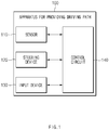
- FIG. 1 is a block diagram illustrating a configuration of an apparatus for providing a driving path in a vehicle in some forms of the present disclosure.
- an apparatus 100 for providing a driving path in a vehicle in some forms of the present disclosure may include a sensor 110, a steering device 120, an input device 130, and a control circuit 140.
- the apparatus 100 for providing a driving path in FIG. 1 may be a portion of an autonomous system and may be loaded into the vehicle.
- the sensor 110 may be configured to sense information about the vehicle loaded with the apparatus 100 for providing the driving path and information about an external object.
- the sensor 110 may sense a preceding vehicle, a following vehicle, a side vehicle, a line on a road, a median strip, a guide rail, another external object, and the like, and may sense a speed, a steering angle, a steering torque, a wheel speed, a yaw rate, and the like of the vehicle.
- the sensor 110 may include, for example, a camera, a radar, a light detection and ranging (LiDAR), a speed sensor, an angle sensor, a torque sensor, a wheel speed sensor, and/or a yaw rate sensor.
- LiDAR light detection and ranging
- the steering device 120 may adjust a driving direction of the vehicle.
- the steering device 120 may include a steering wheel or the like and may be controlled by a driver and/or an autonomous system of the vehicle.
- the input device 130 may be configured to receive a lane change command from the driver of the vehicle.
- the input device 130 may be, for example, a turn signal lever, a switch, and/or a button.
- the control circuit 140 may be electrically connected with the sensor 110, the steering device 120, and the input device 130.
- the control circuit 140 may control the sensor 110, the steering device 120, and the input device 130 and may perform a variety of data processing and various arithmetic operations.
- the control circuit 140 may be, for example, an electronic control unit (ECU), a micro controller unit (MCU), or a sub-controller, which is loaded into the vehicle.
- ECU electronice control unit
- MCU micro controller unit
- sub-controller which is loaded into the vehicle.
- control circuit 140 may control the vehicle to travel along a deviated path in a driving lane of the vehicle, based on at least a portion of the information obtained by the sensor 110 or an operation of the steering device 120.
- the control circuit 140 may determine an intention of the driver to perform deviated driving, based on information of the sensor 110 and/or an operation of the steering device 120.
- the control circuit 140 may perform deviated driving in the driving lane depending to an intention of the driver or a situation outside the vehicle.
- the control circuit 140 may control the vehicle to complete a lane change and travel along a deviated path in a target lane of the lane change. For example, when the vehicle performs the deviated driving before the lane change command is received, the control circuit 140 may control the vehicle to perform the deviated driving after completing the lane change. When the vehicle performs the deviated driving, the control circuit 140 may consider an intention of the driver to perform the deviated driving.
- the control circuit 140 may determine an intention of the driver to perform deviated driving, based on an operation of the steering device 120. While the driver intends to perform the deviated driving, when a lane change command is received, the control circuit 140 may generate a deviated path in a target lane of the lane change. For example, when a steering torque greater than a specified value is generated during a specified time and when the vehicle is away from the center of its driving lane over a specified distance, the control circuit 140 may determine that the driver intends to perform a deviated driving by controlling the steering vehicle 120.
- the control circuit 140 may generate a lane centering path in the target lane. For example, when a steering torque less than or equal to the specified value is generated during the specified time and when the vehicle is away from the center of the driving lane over the specified distance, since the driver does not control the steering device 120 to perform the deviated driving, the control circuit 140 may determine that the driver does not intend to perform the deviated driving.
- the control circuit 140 may generate a deviated path in the target lane such that the vehicle is away from the external object.
- the control circuit 140 may perform a deviated driving in a direction away from the external object. After the vehicle enters the target lane, the control circuit 140 may determine whether to generate a deviated path in the target lane in consideration of the external object located on the lane neighboring to the target lane.
- the control circuit 140 may control vehicle to perform lane centering. For example, when a lateral position error (e.g., a distance between a path generated by the system and a real driving path) is greater than a specified value during a specified time, the control circuit 140 may determine that path following performance of the vehicle is degraded and may control the vehicle to travel along a lane centering path in the target lane.
- a lateral position error e.g., a distance between a path generated by the system and a real driving path
- control circuit 140 may determine that there is a high probability that the path following performance of the vehicle will be degraded and may control the vehicle to travel along the lane centering path in the target lane.
- a specified value e.g., a curvature of a road is small
- the control circuit 140 may control the vehicle to travel along the lane centering path in the target lane until the following vehicle passes the vehicle.
- the control circuit 140 may detect the following vehicle on the lane neighboring to the target lane using the sensor 110.
- the control circuit 140 may determine whether the following vehicle approaches the vehicle, based on a relative speed between the vehicle and the following vehicle.
- the control circuit 140 may control the vehicle to travel along the lane centering path to avoid close proximity to the following vehicle.
- the control circuit 140 may control the vehicle to travel along a deviated path in the target lane after the following vehicle passes the vehicle.
- FIG. 2 is a block diagram illustrating a software module included in an apparatus for providing a driving path in a vehicle in some forms of the present disclosure.
- the apparatus for providing the driving path in some forms of the present disclosure may include a deviated path generator 210, a lane change path generator 220, a lane change completion determining device 230, an avoidance object determining device 240, and a conversion path determining device 250.
- the deviated path generator 210 may determine whether an external object exists within a distance capable of giving a driver of the vehicle uneasiness on a lane neighboring to a driving lane of the vehicle. For example, when the external object exists during a specified time in a specified area from the vehicle, the deviated path generator 210 may determine that there is an object to be avoided. The deviated path generator 210 may determine whether a deviation occurs in the driving lane by steering control of the driver, a lateral gradient of a driving road of the vehicle, or a curvature of the road. When there is the object to be avoided or when the deviation occurs in the driving lane, the deviated path generator 210 may generate a deviated path in the driving lane.
- the lane change path generator 220 may generate a path for a lane change.
- the lane change path generator 220 may determine whether there is a probability that collision will occur during the lane change. When there is no possibility of collision, the lane change path generator 220 may generate a lane change path.
- the lane change path generator 220 may determine that it is impossible to perform a lane change and may fail to generate a path for the lane change.
- the lane change path generator 220 may generate a lane change path.
- the lane change completion determining device 230 may determine whether the vehicle enters a target lane and whether a target vehicle is arranged on the center of a lane.
- the avoidance object determining device 240 may determine whether an object to be avoided exists on a lane neighboring to the target lane.
- the conversion path determining device 250 may generate a lane centering path or a deviated path and may control the vehicle to travel along the generated path.
- the conversion path determining device 250 may determine that path following performance is degraded by disturbance and may control the vehicle to follow the lane center.
- the conversion path determining device 250 may determine that there is a high probability that path following performance will be degraded and may control the vehicle to follow the lane center.
- the conversion path determining device 250 may generate a deviated path in a lane in a direction away from the object to be avoided and may control the vehicle to travel along the deviated path.
- the conversion path determining device 250 may control the vehicle to perform the deviated driving by reflecting the intention of the driver.
- FIG. 3 is a drawing illustrating an exemplary operation of an apparatus for providing a driving path in a vehicle in some forms of the present disclosure.
- a vehicle 310 may perform a lane change toward a target lane from its driving lane.
- the vehicle 310 may turn on/off a left turn signal.
- the vehicle 310 may be traveling along a deviated path.
- the vehicle 310 may perform lane keeping control during a specified time interval after the lane change command is received and may then initiate line approaching control.
- the vehicle 310 may perform the line approaching control toward a line between the driving lane and the target lane.
- the vehicle 310 may move toward the line in a lateral direction.
- the vehicle 310 may complete the line approaching control within a second time interval.
- the vehicle 310 may perform lane entering control. While the lane entering control is performed, a wheel of the vehicle 310 may pass the line. The vehicle 310 may move toward the target lane in the lateral direction. The lane entering control may continue until all wheels of the vehicle 310 pass the line from the wheel of the vehicle 310 starts to pass the line.
- the vehicle 310 may perform lane keeping control.
- the vehicle 310 may move toward the center of the target lane in the lateral direction.
- the vehicle 310 may turn off the left turn signal.
- the vehicle 310 may generate a deviated path in the lane in consideration of a deviated driving state, a location of an external object, and the like when receiving the lane change command and may travel along the deviated path.
- FIG. 4 is a drawing illustrating an exemplary operation of an apparatus for providing a driving path in a vehicle in some forms of the present disclosure.
- a vehicle 410 in some forms of the present disclosure may detect an external object 420 located on a lane neighboring to a lane where the vehicle 410 is traveling.
- the vehicle 410 may determine whether the external object 420 exists within a specified area.
- the vehicle 410 may determine whether the external object 420 exists within a specified distance Z2 (e.g., 5 m) in a longitudinal direction from a front bumper and a rear bumper of the vehicle 410 and within a specified distance Z3 (e.g., 30 cm) in a lateral direction from a line.
- a specified distance Z2 e.g., 5 m
- Z3 e.g. 30 cm
- the vehicle 410 may release the external object 420 from the object to be avoided.
- the vehicle 420 may generate a deviated path in a right direction in the lane and may perform deviated driving along the generated path.
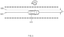
- FIG. 5 is a drawing illustrating an exemplary operation of an apparatus for providing a driving path in a vehicle in some forms of the present disclosure.
- a vehicle 510 in some forms of the present disclosure may travel along a centering path 520 in a lane where it is traveling.
- the vehicle 510 may perform deviated driving depending on an operation of a steering wheel of its driver.
- the vehicle 510 may generate a deviated path 530.
- the vehicle 510 may determine that the driver has an intention to perform deviated driving. While the vehicle 510 travels along the deviated path 530, when a lane change command is received, the vehicle 510 may generate a deviated path in a changed lane after the lane change and may travel along the deviated path.
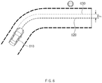
- FIG. 6 is a drawing illustrating an exemplary operation of an apparatus for providing a driving path in a vehicle in some forms of the present disclosure.
- a vehicle 610 in some forms of the present disclosure may travel along a centering path 620 in a lane where it is traveling.
- the vehicle 610 may travel in a state where it departs from the centering path 620 by a lateral gradient of a road where it is traveling or a curvature of the road.
- the vehicle 610 may generate a deviated path 630.
- the vehicle 610 may determine that its driver does not have an intention to perform deviated driving.
- the vehicle 610 While the vehicle 610 travels along the deviated path 630, when a lane change command is received, the vehicle 610 may generate a centering path after a lane change and may travel along the centering path. Although the lane change command is received, the vehicle 610 may fail to perform a lane change.
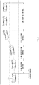
- FIG. 7 is a drawing illustrating an exemplary operation of an apparatus for providing a driving path in a vehicle in some forms of the present disclosure.
- the vehicle in some forms of the present disclosure may travel along a deviated path 720 in response to an external object or an operation of a steering wheel of its driver.
- the vehicle may generate a lane change path 730 including the deviated path 720 and a deviated path 740.
- a distance between the deviated path 740 and a lane centering path 750 may be set to correspond to a distance between the deviated path 720 and a lane centering path 710.
- the lane change path 730 may be generated in consideration of an intention of the driver to perform deviated driving.
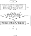
- FIG. 8 is a flowchart illustrating a method for providing a driving path in a vehicle in some forms of the present disclosure.
- a vehicle including an apparatus 100 for providing a driving path in FIG. 1 performs a process of FIG. 8 .
- an operation described as being by the vehicle may be understood as being controlled by a control circuit 140 of the apparatus 100 for providing the driving path.
- the vehicle may control itself to travel along a deviated path in its driving lane based on at least a portion of information about the vehicle, information about an external object, or an operation of a steering device of the vehicle.
- the vehicle may perform deviated driving depending on lateral acceleration of the vehicle, proximity of the external object, an operation of the steering wheel of the driver, and/or the like.
- the vehicle may receive a lane change command from its driver.
- the vehicle may receive an input of the driver to its turn signal lever.
- the vehicle may control itself to complete a lane change and travel along a deviated path in a target lane of the lane change. For example, when the vehicle performs deviated driving upon the reception of the lane change command, it may perform deviated driving after the lane change. The vehicle may consider an intention of the driver to perform deviated driving and may consider a surrounding object capable of giving the driver uneasiness.
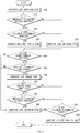
- FIG. 9 is a flowchart illustrating a method for providing a driving path in a vehicle in some forms of the present disclosure.
- a vehicle including an apparatus 100 for providing a driving path in FIG. 1 performs a process of FIG. 9 .
- an operation described as being by the vehicle may be understood as being controlled by a control circuit 140 of the apparatus 100 for providing the driving path.
- the vehicle may generate a lane centering path.
- the vehicle may travel along the lane centering path.
- the vehicle may determine whether it is necessary to perform deviated driving. For example, the vehicle may determine whether there is an external object capable of giving its driver uneasiness or whether the driver has an intention to perform deviated driving (e.g., an operation of the driver for its steering wheel).
- the vehicle may determine whether path following performance is degraded. For example, the vehicle may determine whether the path following performance is degraded with reference to a lateral gradient of a road where the vehicle is traveling, lateral acceleration of the vehicle, and/or the like.
- the vehicle may generate a deviated path in a lane where the vehicle is traveling.
- the vehicle may travel along the deviated path.
- the vehicle may generate a lane centering path.
- the vehicle may travel along the lane centering path.
- the vehicle may receive a lane change command.
- the vehicle may receive the lane change command from the driver through its turn signal lever.
- the vehicle may determine whether it is possible to perform a lane change. For example, the vehicle may determine whether it is possible to perform the lane change, based on a probability of collision, whether path following performance is degraded, a speed of the vehicle, a curvature of the road, and/or the like.
- the vehicle may generate a lane change path.
- the vehicle may travel along the lane change path.
- the vehicle may determine whether it enters a target lane.
- the vehicle may travel along the lane change path until it enters the target lane.
- the lane change may be ended.
- the vehicle may determine whether it is necessary to perform deviated driving. For example, the vehicle may determine whether an external object capable of giving the driver uneasiness exists within a specified area on the changed lane, whether the driver intends to performs deviated driving before the lane change, or whether the driver currently intends to perform deviated driving.
- the vehicle may determine whether path following performance is degraded.
- the vehicle may generate a deviated path in the lane.
- the vehicle may travel along the deviated path.
- the vehicle may generate a lane centering path.
- the vehicle may travel along the lane centering path.
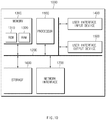
- FIG. 10 is a block diagram illustrating a configuration of a computing system in some forms of the present disclosure.
- a computing system 1000 may include at least one processor 1100, a memory 1300, a user interface input device 1400, a user interface output device 1500, a storage 1600, and a network interface 1700, which are connected with each other via a bus 1200.
- the processor 1100 may be a central processing unit (CPU) or a semiconductor device for performing processing of instructions stored in the memory 1300 and/or the storage 1600.
- CPU central processing unit
- Each of the memory 1300 and the storage 1600 may include various types of volatile or non-volatile storage media.
- the memory 1300 may include a read only memory (ROM) and a random access memory (RAM).
- the operations of the methods or algorithms described in some forms of the present disclosure disclosed in the specification may be directly implemented with a hardware module, a software module, or combinations thereof, executed by the processor 1100.
- the software module may reside on a storage medium (i.e., the memory 1300 and/or the storage 1600) such as a RAM, a flash memory, a ROM, an erasable and programmable ROM (EPROM), an electrically EPROM (EEPROM), a register, a hard disc, a removable disc, or a compact disc-ROM (CD-ROM).
- An exemplary storage medium may be coupled to the processor 1100.
- the processor 1100 may read out information from the storage medium and may write information in the storage medium.
- the storage medium may be integrated with the processor 1100.
- the processor and storage medium may reside in an application specific integrated circuit (ASIC).
- the ASIC may reside in a user terminal.
- the processor and storage medium may reside as a separate component of the user terminal.
- the apparatus for providing the driving path in the vehicle in some forms of the present disclosure may provide a path in which the intention of the driver is reflected upon an automatic lane change by determining the intention of the driver and providing a deviated driving path.
Abstract
Description
- The present application claims priority to and the benefit of Korean Patent Application No.
10-2018-0142013 US Patent Application No. 62/655,831, filed on April 11, 2018 - The present disclosure relates to an apparatus and method for providing a driving path in a vehicle upon a lane change of the vehicle.
- The statements in this section merely provide background information related to the present disclosure and may not constitute prior art.
- With the development of the auto industry, an autonomous system and a driving assistance system which facilitates partially autonomous driving (hereinafter, for convenience of description, both of autonomous driving and driving assistance are referred to as "autonomous driving") have been developed. The autonomous system may provide a variety of functions, for example, setting speed keeping, vehicle-to-vehicle distance keeping, lane keeping, and a lane change. The autonomous system may perform autonomous driving using various devices such as a sensor for sensing environments outside the vehicle, a sensor for sensing information about the vehicle, a global positioning system (GPS), a detailed map, a driver state monitoring system, a steering actuator, an acceleration/deceleration actuator, a communication circuit, and a control circuit (e.g., an electronic control unit (ECU)). The autonomous system may generate a path for the autonomous driving and may perform a lane change along the generated path.
- While performing the autonomous driving, the vehicle may travel along a path following the center of a lane where it is traveling. The vehicle may travel along a deviated path which departs from the lane center in the lane by an intention of its driver. When the vehicle performs an automatic lane change, in some cases, there is a need for reflecting the above-mentioned deviated driving to generate a path.
- An aspect of the present disclosure provides an apparatus and method for performing a lane change and generating and providing a deviated driving path in a target lane of the lane change.
- The technical problems to be solved by the present inventive concept are not limited to the aforementioned problems, and any other technical problems not mentioned herein will be clearly understood from the following description by those skilled in the art to which the present disclosure pertains.
- In one aspect of the present disclosure, an apparatus for providing a driving path in a vehicle may include: one or more sensors configured to obtain information about the vehicle and information about an external object, a steering device, an input device configured to receive a lane change command from a driver of the vehicle, and a control circuit configured to be electrically connected with the one or more sensors, the steering device, and the input device. The control circuit may be configured to control the vehicle to travel along a deviated path in a driving path of the vehicle based on at least a portion of the information obtained by the one or more sensors or an operation of the steering device and control the vehicle to complete a lane change and travel along a deviated path in a target lane of the lane change, when the lane change command is received by the input device while the vehicle travels along the deviated path in the driving path.
- In some forms of the present disclosure, the control circuit may be configured to determine an intention of a driver of the vehicle to perform deviated driving, based on the operation of the steering device and generate the deviated path in the target lane, when the lane change command is received while the driver intends to perform the deviated driving.
- In some forms of the present disclosure, the control circuit may be configured to determine that the driver intends to perform the deviated driving, when a steering torque greater than a specified value is generated during a specified time and when the vehicle is away from the center of the driving lane over a specified distance.
- In some forms of the present disclosure, the control circuit may be configured to determine an intention of a driver of the vehicle to perform deviated driving, based on the operation of the steering device and generate a lane centering path in the target lane, when the lane change command is received while the driver does not intend to perform the deviated driving.
- In some forms of the present disclosure, the control circuit may be configured to determine that the driver does not intend to perform the deviated driving, when a steering torque less than or equal to a specified value is generated during a specified time and the vehicle is away from the center of the driving lane over a specified distance.
- In some forms of the present disclosure, the control circuit may be configured to generate the deviated path in the target lane such that the vehicle is away from the external object, when the external object is detected in a specified area of a lane neighboring to the target lane.
- In some forms of the present disclosure, the control circuit may be configured to determine whether to generate the deviated path in the target lane, after the vehicle enters the target lane.
- In some forms of the present disclosure, the control circuit may be configured to control the vehicle to travel along a lane centering path in the target lane, when a lateral position error is greater than a specified value during a specified time.
- In some forms of the present disclosure, the control circuit may be configured to control the vehicle to travel along a lane centering path in the target lane, when lateral acceleration of the vehicle is greater than a specified value.
- In some forms of the present disclosure, a method for providing a driving path in a vehicle may include: controlling the vehicle to travel along a deviated path in a driving path of the vehicle based on at least a portion of information about the vehicle, information about an external object, or an operation of a steering wheel of the vehicle and controlling the vehicle to complete a lane change and travel along a deviated path in a target lane of the lane change, when the lane change command is received from a driver of the vehicle while the vehicle travels along the deviated path in the driving path.
- In some forms of the present disclosure, the controlling the vehicle to travel along the deviated path in the driving lane may include determining an intention of the driver of the vehicle to perform deviated driving, based on the operation of the steering device. The controlling the vehicle to travel along the deviated path in the target lane may include generating the deviated path in the target lane, when the lane change command is received while the driver intends to perform the deviated driving.
- In some forms of the present disclosure, the method may further include generating a lane centering path in the target lane, when the lane change command is received while the driver does not intend to perform the deviated driving.
- In some forms of the present disclosure, the controlling the vehicle to travel along the deviated path in the target lane may include generating the deviated path in the target lane such that the vehicle is away from the external object, when the external object is detected in a specified area of a lane neighboring to the target lane.
- In some forms of the present disclosure, the method may further include controlling the vehicle to travel along a lane centering path in the target lane, when a lateral position error is greater than a specified value during a specified time.
- In some forms of the present disclosure, the method may further include controlling the vehicle to travel along a lane centering path in the target lane, when lateral acceleration of the vehicle is greater than a specified value.
- Further areas of applicability will become apparent from the description provided herein. It should be understood that the description and specific examples are intended for purposes of illustration only and are not intended to limit the scope of the present disclosure.
- In order that the disclosure may be well understood, there will now be described various forms thereof, given by way of example, reference being made to the accompanying drawings, in which:
-
FIG. 1 is a block diagram illustrating a configuration of an apparatus for providing a driving path in a vehicle in one form of the present disclosure; -
FIG. 2 is a block diagram illustrating a software module included in an apparatus for providing a driving path in a vehicle in one form of the present disclosure; -
FIG. 3 is a drawing illustrating an exemplary operation of an apparatus for providing a driving path in a vehicle in one form of the present disclosure; -
FIG. 4 is a drawing illustrating an exemplary operation of an apparatus for providing a driving path in a vehicle in one form of the present disclosure; -
FIG. 5 is a drawing illustrating an exemplary operation of an apparatus for providing a driving path in a vehicle in one form of the present disclosure; -
FIG. 6 is a drawing illustrating an exemplary operation of an apparatus for providing a driving path in a vehicle in one form of the present disclosure; -
FIG. 7 is a drawing illustrating an exemplary operation of an apparatus for providing a driving path in a vehicle in one form of the present disclosure; -
FIG. 8 is a flowchart illustrating a method for providing a driving path in a vehicle in one form of the present disclosure; -
FIG. 9 is a flowchart illustrating a method for providing a driving path in a vehicle in one form of the present disclosure; and -
FIG. 10 is a block diagram illustrating a configuration of a computing system in one form of the present disclosure. - The drawings described herein are for illustration purposes only and are not intended to limit the scope of the present disclosure in any way.
- The following description is merely exemplary in nature and is not intended to limit the present disclosure, application, or uses. It should be understood that throughout the drawings, corresponding reference numerals indicate like or corresponding parts and features.
- In describing elements of some forms of the present disclosure, the terms 1st, 2nd, first, second, A, B, (a), (b), and the like may be used herein. These terms are only used to distinguish one element from another element, but do not limit the corresponding elements irrespective of the nature, turn, or order of the corresponding elements. Unless otherwise defined, all terms used herein, including technical or scientific terms, have the same meanings as those generally understood by those skilled in the art to which the present disclosure pertains. Such terms as those defined in a generally used dictionary are to be interpreted as having meanings equal to the contextual meanings in the relevant field of art, and are not to be interpreted as having ideal or excessively formal meanings unless clearly defined as having such in the present application.
-
FIG. 1 is a block diagram illustrating a configuration of an apparatus for providing a driving path in a vehicle in some forms of the present disclosure. - Referring to
FIG. 1 , anapparatus 100 for providing a driving path in a vehicle in some forms of the present disclosure may include asensor 110, asteering device 120, aninput device 130, and acontrol circuit 140. Theapparatus 100 for providing a driving path inFIG. 1 may be a portion of an autonomous system and may be loaded into the vehicle. - The
sensor 110 may be configured to sense information about the vehicle loaded with theapparatus 100 for providing the driving path and information about an external object. Thesensor 110 may sense a preceding vehicle, a following vehicle, a side vehicle, a line on a road, a median strip, a guide rail, another external object, and the like, and may sense a speed, a steering angle, a steering torque, a wheel speed, a yaw rate, and the like of the vehicle. Thesensor 110 may include, for example, a camera, a radar, a light detection and ranging (LiDAR), a speed sensor, an angle sensor, a torque sensor, a wheel speed sensor, and/or a yaw rate sensor. - The
steering device 120 may adjust a driving direction of the vehicle. Thesteering device 120 may include a steering wheel or the like and may be controlled by a driver and/or an autonomous system of the vehicle. - The
input device 130 may be configured to receive a lane change command from the driver of the vehicle. Theinput device 130 may be, for example, a turn signal lever, a switch, and/or a button. - The
control circuit 140 may be electrically connected with thesensor 110, thesteering device 120, and theinput device 130. Thecontrol circuit 140 may control thesensor 110, thesteering device 120, and theinput device 130 and may perform a variety of data processing and various arithmetic operations. Thecontrol circuit 140 may be, for example, an electronic control unit (ECU), a micro controller unit (MCU), or a sub-controller, which is loaded into the vehicle. - In some forms of the present disclosure, the
control circuit 140 may control the vehicle to travel along a deviated path in a driving lane of the vehicle, based on at least a portion of the information obtained by thesensor 110 or an operation of thesteering device 120. Thecontrol circuit 140 may determine an intention of the driver to perform deviated driving, based on information of thesensor 110 and/or an operation of thesteering device 120. Thecontrol circuit 140 may perform deviated driving in the driving lane depending to an intention of the driver or a situation outside the vehicle. - In some forms of the present disclosure, while the vehicle travels along the deviated path in the driving lane, when a lane change command is received by the
input device 130, thecontrol circuit 140 may control the vehicle to complete a lane change and travel along a deviated path in a target lane of the lane change. For example, when the vehicle performs the deviated driving before the lane change command is received, thecontrol circuit 140 may control the vehicle to perform the deviated driving after completing the lane change. When the vehicle performs the deviated driving, thecontrol circuit 140 may consider an intention of the driver to perform the deviated driving. - In some forms of the present disclosure, the
control circuit 140 may determine an intention of the driver to perform deviated driving, based on an operation of thesteering device 120. While the driver intends to perform the deviated driving, when a lane change command is received, thecontrol circuit 140 may generate a deviated path in a target lane of the lane change. For example, when a steering torque greater than a specified value is generated during a specified time and when the vehicle is away from the center of its driving lane over a specified distance, thecontrol circuit 140 may determine that the driver intends to perform a deviated driving by controlling thesteering vehicle 120. - In some forms of the present disclosure, while the driver does not intend to perform a deviated driving, when a lane change command is received, the
control circuit 140 may generate a lane centering path in the target lane. For example, when a steering torque less than or equal to the specified value is generated during the specified time and when the vehicle is away from the center of the driving lane over the specified distance, since the driver does not control thesteering device 120 to perform the deviated driving, thecontrol circuit 140 may determine that the driver does not intend to perform the deviated driving. - In some forms of the present disclosure, when an external object is detected in a specified area of a lane neighboring to the target lane, the
control circuit 140 may generate a deviated path in the target lane such that the vehicle is away from the external object. When the external object on the lane neighboring to the target lane is adjacent to the vehicle, the driver may feel anxious. When the external object on the lane neighboring to the target lane is located within a specified area from the vehicle, thecontrol circuit 140 may perform a deviated driving in a direction away from the external object. After the vehicle enters the target lane, thecontrol circuit 140 may determine whether to generate a deviated path in the target lane in consideration of the external object located on the lane neighboring to the target lane. - In some forms of the present disclosure, when it is not safe to perform the deviated driving, the
control circuit 140 may control vehicle to perform lane centering. For example, when a lateral position error (e.g., a distance between a path generated by the system and a real driving path) is greater than a specified value during a specified time, thecontrol circuit 140 may determine that path following performance of the vehicle is degraded and may control the vehicle to travel along a lane centering path in the target lane. For another example, when lateral acceleration of the vehicle is greater than a specified value (e.g., a curvature of a road is small), thecontrol circuit 140 may determine that there is a high probability that the path following performance of the vehicle will be degraded and may control the vehicle to travel along the lane centering path in the target lane. - In some forms of the present disclosure, when a following vehicle approaches the vehicle from a lane neighboring to the target lane, the
control circuit 140 may control the vehicle to travel along the lane centering path in the target lane until the following vehicle passes the vehicle. When the vehicle enters the target lane, thecontrol circuit 140 may detect the following vehicle on the lane neighboring to the target lane using thesensor 110. Thecontrol circuit 140 may determine whether the following vehicle approaches the vehicle, based on a relative speed between the vehicle and the following vehicle. When the following vehicle approaches the vehicle, thecontrol circuit 140 may control the vehicle to travel along the lane centering path to avoid close proximity to the following vehicle. Thecontrol circuit 140 may control the vehicle to travel along a deviated path in the target lane after the following vehicle passes the vehicle. -
FIG. 2 is a block diagram illustrating a software module included in an apparatus for providing a driving path in a vehicle in some forms of the present disclosure. - Referring to
FIG. 2 , the apparatus for providing the driving path in some forms of the present disclosure may include a deviatedpath generator 210, a lanechange path generator 220, a lane changecompletion determining device 230, an avoidanceobject determining device 240, and a conversionpath determining device 250. - The deviated
path generator 210 may determine whether an external object exists within a distance capable of giving a driver of the vehicle uneasiness on a lane neighboring to a driving lane of the vehicle. For example, when the external object exists during a specified time in a specified area from the vehicle, the deviatedpath generator 210 may determine that there is an object to be avoided. The deviatedpath generator 210 may determine whether a deviation occurs in the driving lane by steering control of the driver, a lateral gradient of a driving road of the vehicle, or a curvature of the road. When there is the object to be avoided or when the deviation occurs in the driving lane, the deviatedpath generator 210 may generate a deviated path in the driving lane. - When a lane change command of the driver is received, the lane
change path generator 220 may generate a path for a lane change. The lanechange path generator 220 may determine whether there is a probability that collision will occur during the lane change. When there is no possibility of collision, the lanechange path generator 220 may generate a lane change path. When a deviation the driver does not intend occurs (e.g., when a deviation occurs by a lateral gradient of the road or a curvature of the road), the lanechange path generator 220 may determine that it is impossible to perform a lane change and may fail to generate a path for the lane change. When a lane change command of the driver is received, when there is no possibility of collision, and when there is no deviation by a control limit, the lanechange path generator 220 may generate a lane change path. - The lane change
completion determining device 230 may determine whether the vehicle enters a target lane and whether a target vehicle is arranged on the center of a lane. - When the vehicle enters the target lane, the avoidance
object determining device 240 may determine whether an object to be avoided exists on a lane neighboring to the target lane. - When the lane change is completed, the conversion
path determining device 250 may generate a lane centering path or a deviated path and may control the vehicle to travel along the generated path. When a lateral position error greater than or equal to a reference value is maintained over a reference time, the conversionpath determining device 250 may determine that path following performance is degraded by disturbance and may control the vehicle to follow the lane center. Similarly, when lateral acceleration is greater than or equal to a reference value, the conversionpath determining device 250 may determine that there is a high probability that path following performance will be degraded and may control the vehicle to follow the lane center. When an object to be avoided exists on a lane neighboring to the target lane, the conversionpath determining device 250 may generate a deviated path in a lane in a direction away from the object to be avoided and may control the vehicle to travel along the deviated path. When deviated driving is performed according to an intention of the driver before a lane change, the conversionpath determining device 250 may control the vehicle to perform the deviated driving by reflecting the intention of the driver. -
FIG. 3 is a drawing illustrating an exemplary operation of an apparatus for providing a driving path in a vehicle in some forms of the present disclosure. - Referring to
FIG. 3 , avehicle 310 may perform a lane change toward a target lane from its driving lane. When a lane change command is received, thevehicle 310 may turn on/off a left turn signal. When the lane change command is received, thevehicle 310 may be traveling along a deviated path. Thevehicle 310 may perform lane keeping control during a specified time interval after the lane change command is received and may then initiate line approaching control. - The
vehicle 310 may perform the line approaching control toward a line between the driving lane and the target lane. Thevehicle 310 may move toward the line in a lateral direction. Thevehicle 310 may complete the line approaching control within a second time interval. - When the line approaching control is completed, the
vehicle 310 may perform lane entering control. While the lane entering control is performed, a wheel of thevehicle 310 may pass the line. Thevehicle 310 may move toward the target lane in the lateral direction. The lane entering control may continue until all wheels of thevehicle 310 pass the line from the wheel of thevehicle 310 starts to pass the line. - When the lane entering control is completed, the
vehicle 310 may perform lane keeping control. Thevehicle 310 may move toward the center of the target lane in the lateral direction. When moving to the center of the target lane, thevehicle 310 may turn off the left turn signal. Thevehicle 310 may generate a deviated path in the lane in consideration of a deviated driving state, a location of an external object, and the like when receiving the lane change command and may travel along the deviated path. -
FIG. 4 is a drawing illustrating an exemplary operation of an apparatus for providing a driving path in a vehicle in some forms of the present disclosure. - Referring to
FIG. 4 , avehicle 410 in some forms of the present disclosure may detect anexternal object 420 located on a lane neighboring to a lane where thevehicle 410 is traveling. Thevehicle 410 may determine whether theexternal object 420 exists within a specified area. For example, thevehicle 410 may determine whether theexternal object 420 exists within a specified distance Z2 (e.g., 5 m) in a longitudinal direction from a front bumper and a rear bumper of thevehicle 410 and within a specified distance Z3 (e.g., 30 cm) in a lateral direction from a line. When theexternal object 420 exists within area Z1-Z3, thevehicle 410 may determine theexternal object 420 as an object to be avoided. When theexternal object 420 moves from area Z1-Z3 to area Z2-Z3, thevehicle 410 may release theexternal object 420 from the object to be avoided. When theexternal object 420 exists within a specified area in a left direction of thevehicle 410, thevehicle 420 may generate a deviated path in a right direction in the lane and may perform deviated driving along the generated path. -
FIG. 5 is a drawing illustrating an exemplary operation of an apparatus for providing a driving path in a vehicle in some forms of the present disclosure. - Referring to
FIG. 5 , avehicle 510 in some forms of the present disclosure may travel along a centeringpath 520 in a lane where it is traveling. Thevehicle 510 may perform deviated driving depending on an operation of a steering wheel of its driver. When thevehicle 510 travels in a state where it deviates from the centeringpath 520 over a specified distance Dth by an operation of the steering wheel during a specified time, it may generate a deviatedpath 530. In this case, thevehicle 510 may determine that the driver has an intention to perform deviated driving. While thevehicle 510 travels along the deviatedpath 530, when a lane change command is received, thevehicle 510 may generate a deviated path in a changed lane after the lane change and may travel along the deviated path. -
FIG. 6 is a drawing illustrating an exemplary operation of an apparatus for providing a driving path in a vehicle in some forms of the present disclosure. - Referring to
FIG. 6 , avehicle 610 in some forms of the present disclosure may travel along a centeringpath 620 in a lane where it is traveling. Thevehicle 610 may travel in a state where it departs from the centeringpath 620 by a lateral gradient of a road where it is traveling or a curvature of the road. When thevehicle 610 travels in a state where it deviates from the centeringpath 620 over a specified distance Dth by disturbance (e.g., when a steering torque is less than or equal to a specified value) rather than an operation of a steering wheel of thevehicle 610, it may generate a deviatedpath 630. In this case, thevehicle 610 may determine that its driver does not have an intention to perform deviated driving. While thevehicle 610 travels along the deviatedpath 630, when a lane change command is received, thevehicle 610 may generate a centering path after a lane change and may travel along the centering path. Although the lane change command is received, thevehicle 610 may fail to perform a lane change. -
FIG. 7 is a drawing illustrating an exemplary operation of an apparatus for providing a driving path in a vehicle in some forms of the present disclosure. - Referring to
FIG. 7 , the vehicle in some forms of the present disclosure may travel along a deviatedpath 720 in response to an external object or an operation of a steering wheel of its driver. When a lane change command is received from the driver, the vehicle may generate alane change path 730 including the deviatedpath 720 and a deviatedpath 740. A distance between the deviatedpath 740 and alane centering path 750 may be set to correspond to a distance between the deviatedpath 720 and alane centering path 710. Thus, thelane change path 730 may be generated in consideration of an intention of the driver to perform deviated driving. -
FIG. 8 is a flowchart illustrating a method for providing a driving path in a vehicle in some forms of the present disclosure. - Hereinafter, it is assumed that a vehicle including an
apparatus 100 for providing a driving path inFIG. 1 performs a process ofFIG. 8 . Furthermore, in a description ofFIG. 8 , an operation described as being by the vehicle may be understood as being controlled by acontrol circuit 140 of theapparatus 100 for providing the driving path. - Referring to
FIG. 8 , inoperation 810, the vehicle may control itself to travel along a deviated path in its driving lane based on at least a portion of information about the vehicle, information about an external object, or an operation of a steering device of the vehicle. For example, the vehicle may perform deviated driving depending on lateral acceleration of the vehicle, proximity of the external object, an operation of the steering wheel of the driver, and/or the like. - In
operation 820, while the vehicle travels along the deviated path in the driving lane, it may receive a lane change command from its driver. For example, the vehicle may receive an input of the driver to its turn signal lever. - When the lane change command is received, in
operation 830, the vehicle may control itself to complete a lane change and travel along a deviated path in a target lane of the lane change. For example, when the vehicle performs deviated driving upon the reception of the lane change command, it may perform deviated driving after the lane change. The vehicle may consider an intention of the driver to perform deviated driving and may consider a surrounding object capable of giving the driver uneasiness. -
FIG. 9 is a flowchart illustrating a method for providing a driving path in a vehicle in some forms of the present disclosure. - Hereinafter, it is assumed that a vehicle including an
apparatus 100 for providing a driving path inFIG. 1 performs a process ofFIG. 9 . Furthermore, in a description ofFIG. 9 , an operation described as being by the vehicle may be understood as being controlled by acontrol circuit 140 of theapparatus 100 for providing the driving path. - Referring to
FIG. 9 , inoperation 905, the vehicle may generate a lane centering path. The vehicle may travel along the lane centering path. - In
operation 910, the vehicle may determine whether it is necessary to perform deviated driving. For example, the vehicle may determine whether there is an external object capable of giving its driver uneasiness or whether the driver has an intention to perform deviated driving (e.g., an operation of the driver for its steering wheel). - When it is determined that it is necessary to perform the deviated driving, in
operation 915, the vehicle may determine whether path following performance is degraded. For example, the vehicle may determine whether the path following performance is degraded with reference to a lateral gradient of a road where the vehicle is traveling, lateral acceleration of the vehicle, and/or the like. - When the path following performance is not degraded, in
operation 920, the vehicle may generate a deviated path in a lane where the vehicle is traveling. The vehicle may travel along the deviated path. - When it is determined that it is unnecessary to perform the deviated driving or when the path following performance is degraded, in
operation 925, the vehicle may generate a lane centering path. The vehicle may travel along the lane centering path. - In
operation 930, the vehicle may receive a lane change command. For example, the vehicle may receive the lane change command from the driver through its turn signal lever. - When the lane change command is received, in
operation 935, the vehicle may determine whether it is possible to perform a lane change. For example, the vehicle may determine whether it is possible to perform the lane change, based on a probability of collision, whether path following performance is degraded, a speed of the vehicle, a curvature of the road, and/or the like. - When it is determined that it is possible to perform the lane change, in
operation 940, the vehicle may generate a lane change path. The vehicle may travel along the lane change path. - In
operation 945, the vehicle may determine whether it enters a target lane. The vehicle may travel along the lane change path until it enters the target lane. When the vehicle enters the target lane, the lane change may be ended. - When the vehicle enters the target lane, in
operation 950, the vehicle may determine whether it is necessary to perform deviated driving. For example, the vehicle may determine whether an external object capable of giving the driver uneasiness exists within a specified area on the changed lane, whether the driver intends to performs deviated driving before the lane change, or whether the driver currently intends to perform deviated driving. - When it is determined that it is necessary to perform the deviated driving, in
operation 955, the vehicle may determine whether path following performance is degraded. - When the path following performance is not degraded, in
operation 960, the vehicle may generate a deviated path in the lane. The vehicle may travel along the deviated path. - When it is determined that it is unnecessary to perform the deviated driving or when the path following performance is degraded, in
operation 965, the vehicle may generate a lane centering path. The vehicle may travel along the lane centering path. -
FIG. 10 is a block diagram illustrating a configuration of a computing system in some forms of the present disclosure. - Referring to
FIG. 10 , acomputing system 1000 may include at least oneprocessor 1100, amemory 1300, a userinterface input device 1400, a userinterface output device 1500, astorage 1600, and anetwork interface 1700, which are connected with each other via abus 1200. - The
processor 1100 may be a central processing unit (CPU) or a semiconductor device for performing processing of instructions stored in thememory 1300 and/or thestorage 1600. Each of thememory 1300 and thestorage 1600 may include various types of volatile or non-volatile storage media. For example, thememory 1300 may include a read only memory (ROM) and a random access memory (RAM). - Thus, the operations of the methods or algorithms described in some forms of the present disclosure disclosed in the specification may be directly implemented with a hardware module, a software module, or combinations thereof, executed by the
processor 1100. The software module may reside on a storage medium (i.e., thememory 1300 and/or the storage 1600) such as a RAM, a flash memory, a ROM, an erasable and programmable ROM (EPROM), an electrically EPROM (EEPROM), a register, a hard disc, a removable disc, or a compact disc-ROM (CD-ROM). An exemplary storage medium may be coupled to theprocessor 1100. Theprocessor 1100 may read out information from the storage medium and may write information in the storage medium. Alternatively, the storage medium may be integrated with theprocessor 1100. The processor and storage medium may reside in an application specific integrated circuit (ASIC). The ASIC may reside in a user terminal. Alternatively, the processor and storage medium may reside as a separate component of the user terminal. - The apparatus for providing the driving path in the vehicle in some forms of the present disclosure may provide a path in which the intention of the driver is reflected upon an automatic lane change by determining the intention of the driver and providing a deviated driving path.
- In addition, various effects directly or indirectly ascertained through the present disclosure may be provided.
- The description of the disclosure is merely exemplary in nature and, thus, variations that do not depart from the substance of the disclosure are intended to be within the scope of the disclosure. Such variations are not to be regarded as a departure from the spirit and scope of the disclosure.
Claims (15)
- An apparatus for providing a driving path in a vehicle, the apparatus comprising:a plurality of sensors configured to obtain information regarding the vehicle and information regarding an external object;a steering device;an input device configured to receive a lane change command from a driver of the vehicle; anda control circuit electrically connected with the plurality of sensors, the steering device, and the input device and configured to:control the vehicle to travel along a deviated path in a driving path of the vehicle based on at least one of the information regarding the vehicle, the information regarding the external object, or an operation of the steering device; andcontrol the vehicle to complete a lane change and travel along the deviated path in a target lane of the changed lane in response to the received lane change command when the vehicle travels along the deviated path in the driving path.
- The apparatus of claim 1, wherein the control circuit is further configured to:determine an intention of the driver to perform a deviated driving based on the operation of the steering device; andgenerate the deviated path in the target lane in response to the received lane change command when the driver is determined to intend to perform the deviated driving.
- The apparatus of claim 1 or 2, wherein the control circuit is configured to determine that the driver intends to perform the deviated driving when:a steering torque greater than a first predetermined value is generated at a first predetermined time; andthe vehicle is away from a center of the driving lane at a distance greater than a predetermined distance.
- The apparatus of one of claims 1 to 3, wherein the control circuit is further configured to:determine the intention of the driver to perform the deviated driving based on the operation of the steering device; andgenerate a lane center path in the target lane in response to the received lane change command when the driver is determined not to intend to perform the deviated driving.
- The apparatus of claim 4, wherein the control circuit is configured to determine that the driver does not intend to perform the deviated driving when:the steering torque less than or equal to the first predetermined value is generated at the first predetermined time; andthe vehicle is away from the center of the driving lane at the distance greater than the predetermined distance.
- The apparatus of one of claims 1 to 5, wherein the control circuit is further configured to:
generate the deviated path in the target lane such that the vehicle is away from the external object when the external object is detected in a specified area of a lane adjoining to the target lane. - The apparatus of claim 6, wherein the control circuit is configured to:
determine whether to generate the deviated path in the target lane after the vehicle enters the target lane. - The apparatus of one of claims 1 to 7, wherein the control circuit is further configured to:
control the vehicle to travel along the lane center path in the target lane when a lateral position error is greater than a second predetermined value at a second predetermined time. - The apparatus of one of claims 1 to 8, wherein the control circuit is further configured to:
control the vehicle to travel along the lane center path in the target lane when a lateral acceleration of the vehicle is greater than a third predetermined value. - The apparatus of one of claims 1 to 9, wherein the control circuit is further configured to:when a following vehicle approaches the vehicle from the lane adjoining to the target lane, control the vehicle to travel along the lane center path in the target lane until the following vehicle passes the vehicle; andcontrol the vehicle to travel along the deviated path in the target lane after the following vehicle passes the vehicle.
- A method for providing a driving path in a vehicle, the method comprising:controlling, with a control circuit, the vehicle to travel along a deviated path in a driving path of the vehicle based on at least one of information regarding the vehicle, information regarding an external object, or an operation of a steering device of the vehicle; andcontrolling, with the control circuit, the vehicle to complete a lane change and travel along the deviated path in a target lane of the changed lane in response to a lane change command received from a driver of the vehicle when the vehicle travels along the deviated path in the driving path.
- The method of claim 11, wherein the method further comprises:determining, with the control circuit, an intention of the driver to perform a deviated driving based on the operation of the steering device; andwhen it is determined that the driver intends to perform the deviated driving, generating, with the control circuit, the deviated path in the target lane in response to the received lane change command.
- The method of claim 11 or 12, wherein controlling the vehicle to travel along the deviated path in the target lane comprises:
when the external object is detected in a specified area of a lane adjoining to the target lane, generating, with the control circuit, the deviated path in the target lane such that the vehicle is away from the external object,. - The method of one of claims 11 to 13, wherein the method further comprises:
when a lateral position error is greater than a first predetermined value at a first predetermined time, controlling, with the control circuit, the vehicle to travel along the lane center path in the target lane. - The method of one of claims 11 to 14, wherein the method further comprises:
when a lateral acceleration of the vehicle is greater than a second predetermined value, controlling, with the control circuit, the vehicle to travel along the lane center path in the target lane.
Applications Claiming Priority (2)
| Application Number | Priority Date | Filing Date | Title |
|---|---|---|---|
| US201862655831P | 2018-04-11 | 2018-04-11 | |
| KR1020180142013A KR20190123663A (en) | 2018-04-11 | 2018-11-16 | Apparatus and method for providing drive path of vehicle |
Publications (1)
| Publication Number | Publication Date |
|---|---|
| EP3552902A1 true EP3552902A1 (en) | 2019-10-16 |
Family
ID=66092156
Family Applications (1)
| Application Number | Title | Priority Date | Filing Date |
|---|---|---|---|
| EP19167267.4A Pending EP3552902A1 (en) | 2018-04-11 | 2019-04-04 | Apparatus and method for providing a driving path to a vehicle |
Country Status (3)
| Country | Link |
|---|---|
| US (1) | US11541889B2 (en) |
| EP (1) | EP3552902A1 (en) |
| CN (1) | CN110371125A (en) |
Cited By (2)
| Publication number | Priority date | Publication date | Assignee | Title |
|---|---|---|---|---|
| CN113954834A (en) * | 2020-07-15 | 2022-01-21 | 荷兰移动驱动器公司 | Lane changing planning method and vehicle-mounted device |
| CN115662186A (en) * | 2022-10-13 | 2023-01-31 | 安徽信息工程学院 | Vehicle obstacle avoidance method and system based on artificial intelligence |
Families Citing this family (7)
| Publication number | Priority date | Publication date | Assignee | Title |
|---|---|---|---|---|
| JP7233537B2 (en) * | 2019-07-05 | 2023-03-06 | 三菱電機株式会社 | VEHICLE INFORMATION EQUIPMENT AND VEHICLE INFORMATION EQUIPMENT CONTROL METHOD |
| DE102019213185A1 (en) * | 2019-09-02 | 2021-03-04 | Volkswagen Aktiengesellschaft | Lateral guidance of a vehicle using environmental data recorded from other vehicles |
| AU2020366019A1 (en) * | 2019-10-16 | 2022-05-05 | Locomation, Inc. | Behaviors that reduce demand on autonomous follower vehicles |
| US11407419B2 (en) * | 2019-12-30 | 2022-08-09 | Baidu Usa Llc | Central line shifting based pre-change lane path planning |
| US11858509B2 (en) * | 2020-03-02 | 2024-01-02 | GM Global Technology Operations LLC | Driver offset request for automated lane following |
| US10814885B1 (en) * | 2020-05-06 | 2020-10-27 | Southern Taiwan University Of Science And Technology | Car and neighboring vehicle lane departure warning system and method |
| WO2022213373A1 (en) * | 2021-04-09 | 2022-10-13 | 华为技术有限公司 | Trajectory planning method and related device |
Citations (4)
| Publication number | Priority date | Publication date | Assignee | Title |
|---|---|---|---|---|
| US6055467A (en) * | 1996-08-16 | 2000-04-25 | Daimlerchrysler Ag | Apparatus for automatic transverse vehicle guidance along a traffic lane |
| EP1074904A1 (en) * | 1999-08-02 | 2001-02-07 | Nissan Motor Company, Limited | Lateral control of vehicle for lane following |
| US20090299573A1 (en) * | 2008-05-27 | 2009-12-03 | Sebastian Thrun | Systems, methods and devices for adaptive steering control of automotive vehicles |
| DE102016216134A1 (en) * | 2016-08-29 | 2018-03-01 | Bayerische Motoren Werke Aktiengesellschaft | Shifting the lateral position of an automated lateral guide to inform the driver of a required lane change |
Family Cites Families (247)
| Publication number | Priority date | Publication date | Assignee | Title |
|---|---|---|---|---|
| US4361202A (en) | 1979-06-15 | 1982-11-30 | Michael Minovitch | Automated road transportation system |
| US5314037A (en) | 1993-01-22 | 1994-05-24 | Shaw David C H | Automobile collision avoidance system |
| DE4313568C1 (en) | 1993-04-26 | 1994-06-16 | Daimler Benz Ag | Guiding motor vehicle driver when changing traffic lanes - using radar devices to detect velocity and spacing of vehicles in next lane and indicate when lane changing is possible |
| DE19821122A1 (en) | 1997-12-15 | 1999-06-17 | Volkswagen Ag | Procedure for controlling speed and distance in overtaking maneuvers |
| JP3824784B2 (en) | 1998-06-30 | 2006-09-20 | 富士通株式会社 | Driving support device, lane change permission determination device, method and recording medium |
| JP2000198458A (en) | 1999-01-08 | 2000-07-18 | Mazda Motor Corp | Control device of vehicle |
| DE10114187A1 (en) | 2001-03-23 | 2002-09-26 | Bosch Gmbh Robert | Overtaking maneuver assistance system for motor vehicle computes overtaking speed from distances of vehicle to be overtaken and immediately preceding vehicle in overtaking lane |
| JP2003025868A (en) | 2001-07-16 | 2003-01-29 | Nissan Motor Co Ltd | Lane-change supporting device for vehicle |
| DE10218010A1 (en) * | 2002-04-23 | 2003-11-06 | Bosch Gmbh Robert | Method and device for lateral guidance support in motor vehicles |
| CA2531662C (en) | 2003-07-07 | 2016-04-26 | Sensomatix Ltd. | Traffic information system |
| DE602004008541T2 (en) | 2003-07-07 | 2008-04-30 | Nissan Motor Co., Ltd., Yokohama | Control system for a vehicle for keeping the lane |
| DE10350779A1 (en) * | 2003-10-30 | 2005-06-02 | Robert Bosch Gmbh | Lane keeping system for a motor vehicle and operating method |
| JP4032253B2 (en) | 2003-12-17 | 2008-01-16 | ソニー株式会社 | Optical communication apparatus and vehicle control method |
| DE102004005815B3 (en) | 2004-02-06 | 2005-06-09 | Audi Ag | Automobile with selectively operated driver support systems and device for combined display of status of driver support systems via combined optical symbol |
| KR100578573B1 (en) | 2004-05-06 | 2006-05-12 | 기아자동차주식회사 | Limiting Speed indication and warning device |
| JP4379199B2 (en) | 2004-05-17 | 2009-12-09 | 日産自動車株式会社 | Lane change support apparatus and method |
| DE102004029369B4 (en) | 2004-06-17 | 2016-09-15 | Robert Bosch Gmbh | Lane change assistant for motor vehicles |
| DE102004048009A1 (en) | 2004-10-01 | 2006-04-06 | Robert Bosch Gmbh | Method and device for driver assistance |
| DE102004048468A1 (en) | 2004-10-05 | 2006-04-13 | Siemens Ag | System and method for setting the speed of a vehicle to a maximum permissible speed |
| EP1849669B1 (en) | 2006-04-28 | 2011-10-05 | Nissan Motor Co., Ltd. | Lane departure prevention apparatus and method for a motor vehicle |
| JP4582052B2 (en) * | 2006-06-07 | 2010-11-17 | トヨタ自動車株式会社 | Driving support device |
| JP4449960B2 (en) * | 2006-08-22 | 2010-04-14 | トヨタ自動車株式会社 | Steering support device |
| JP4525670B2 (en) | 2006-11-20 | 2010-08-18 | トヨタ自動車株式会社 | Travel control plan generation system |
| DE102007005245A1 (en) | 2007-02-02 | 2007-11-22 | Daimlerchrysler Ag | Method for operating a driver assistance system e.g. for motor vehicle, involves using display instrument to show relevant traffic information at given time point |
| JP4748122B2 (en) | 2007-06-28 | 2011-08-17 | 日産自動車株式会社 | Lane departure prevention device |
| JP4366419B2 (en) | 2007-09-27 | 2009-11-18 | 株式会社日立製作所 | Driving support device |
| EP2062796B1 (en) | 2007-11-20 | 2010-08-04 | Nissan Motor Co., Ltd. | Lane deviation prevention device and method |
| JP2009184554A (en) | 2008-02-07 | 2009-08-20 | Denso Corp | Safe travel assisting system |
| DE102008001677A1 (en) | 2008-05-09 | 2009-11-12 | Robert Bosch Gmbh | Assistance system for driver assistance in vehicles |
| US8170739B2 (en) * | 2008-06-20 | 2012-05-01 | GM Global Technology Operations LLC | Path generation algorithm for automated lane centering and lane changing control system |
| US9846049B2 (en) | 2008-07-09 | 2017-12-19 | Microsoft Technology Licensing, Llc | Route prediction |
| DE112010000085A5 (en) | 2009-02-03 | 2012-08-16 | Adc Automotive Distance Control Systems Gmbh | Speed preset for a vehicle with automatic longitudinal control |
| JP5523448B2 (en) | 2009-04-23 | 2014-06-18 | パナソニック株式会社 | Driving support system, information display device, and information display program |
| US8164543B2 (en) | 2009-05-18 | 2012-04-24 | GM Global Technology Operations LLC | Night vision on full windshield head-up display |
| KR101286377B1 (en) | 2009-12-09 | 2013-07-15 | 주식회사 만도 | Method and apparatus for contorlling transient state of lane change, and adaptive cruise control system using the same method |
| DE102010004625A1 (en) | 2010-01-14 | 2011-07-21 | Ford Global Technologies, LLC, Mich. | Method and device for assisting a driver in an overtaking process |
| US8384534B2 (en) | 2010-01-14 | 2013-02-26 | Toyota Motor Engineering & Manufacturing North America, Inc. | Combining driver and environment sensing for vehicular safety systems |
| WO2011111121A1 (en) * | 2010-03-12 | 2011-09-15 | トヨタ自動車株式会社 | Steering support device |
| US8618922B2 (en) | 2010-03-30 | 2013-12-31 | GM Global Technology Operations LLC | Method and system for ensuring operation of limited-ability autonomous driving vehicles |
| DE102010049351A1 (en) | 2010-10-23 | 2012-04-26 | Daimler Ag | A method of operating a brake assist device and brake assist device for a vehicle |
| US8977419B2 (en) * | 2010-12-23 | 2015-03-10 | GM Global Technology Operations LLC | Driving-based lane offset control for lane centering |
| WO2012131405A1 (en) | 2011-03-29 | 2012-10-04 | Josic Ante | Automatic control of maximum speed and automatic control system thereof |
| DE102011016771A1 (en) | 2011-04-12 | 2012-10-18 | Daimler Ag | Device for operating lane change assist in vehicle, has manual operating unit for driver-side activation of lane change, which is coupled to or integrated with direction sensor |
| DE102011016770B4 (en) | 2011-04-12 | 2021-02-04 | Daimler Ag | Method for assisting a driver of a vehicle when changing lanes and device for carrying out the method |
| JP2012226392A (en) * | 2011-04-14 | 2012-11-15 | Honda Elesys Co Ltd | Drive support system |
| US8935071B2 (en) * | 2011-05-05 | 2015-01-13 | GM Global Technology Operations LLC | Optimal fusion of electric park brake and hydraulic brake sub-system functions to control vehicle direction |
| US8670903B2 (en) * | 2011-05-05 | 2014-03-11 | GM Global Technology Operations LLC | Lane centering fail-safe control using differential braking |
| EP2711908A4 (en) | 2011-05-20 | 2015-01-21 | Honda Motor Co Ltd | Lane change assistant system |
| DE102011109618A1 (en) | 2011-08-05 | 2013-02-07 | Daimler Ag | Method for operating vehicle, involves automatically determining driving impairment of driver while activating engagement to brake, steering or drive train function of vehicle, so that vehicle is decelerated to standstill |
| DE102011081892A1 (en) | 2011-08-31 | 2013-02-28 | Robert Bosch Gmbh | Method for lane monitoring and lane monitoring system for a vehicle |
| US8838325B2 (en) | 2011-09-12 | 2014-09-16 | Ford Global Technologies | Vehicle shut-down functionality for peps-equipped vehicles |
| DE102011086241B4 (en) | 2011-11-14 | 2018-04-05 | Robert Bosch Gmbh | Method for the safe parking of a vehicle |
| DE102012001405A1 (en) | 2012-01-26 | 2012-11-22 | Daimler Ag | Method for performing lane change of vehicle from current lane, involves determining whether lane change of vehicle is safely feasible along determined transition trajectory, based on movement of other road users |
| DE102012002304A1 (en) | 2012-02-06 | 2013-08-08 | Audi Ag | Apparatus for automated driving of a motor vehicle and method for operating a motor vehicle |
| JP5868218B2 (en) * | 2012-02-28 | 2016-02-24 | 株式会社日本自動車部品総合研究所 | Vehicle control device |
| US8457827B1 (en) | 2012-03-15 | 2013-06-04 | Google Inc. | Modifying behavior of autonomous vehicle based on predicted behavior of other vehicles |
| JP5754544B2 (en) | 2012-03-22 | 2015-07-29 | トヨタ自動車株式会社 | Brake control device |
| US9315178B1 (en) | 2012-04-13 | 2016-04-19 | Google Inc. | Model checking for autonomous vehicles |
| DE102012008090A1 (en) | 2012-04-21 | 2013-10-24 | Volkswagen Aktiengesellschaft | Method and device for emergency stop of a motor vehicle |
| US8521352B1 (en) | 2012-05-07 | 2013-08-27 | Google Inc. | Controlling a vehicle having inadequate map data |
| KR101896720B1 (en) | 2012-12-24 | 2018-09-07 | 현대자동차주식회사 | Autonomous lane change control system |
| US8798841B1 (en) | 2013-03-14 | 2014-08-05 | GM Global Technology Operations LLC | System and method for improving sensor visibility of vehicle in autonomous driving mode |
| US9751534B2 (en) | 2013-03-15 | 2017-09-05 | Honda Motor Co., Ltd. | System and method for responding to driver state |
| GB2512317A (en) | 2013-03-26 | 2014-10-01 | Jaguar Land Rover Ltd | Vehicle control system and method |
| KR101439017B1 (en) | 2013-04-11 | 2014-10-30 | 현대자동차주식회사 | System for controlling change of lane |
| US20140309855A1 (en) | 2013-04-12 | 2014-10-16 | Bao Tran | Smart car with automatic signalling |
| US8874301B1 (en) | 2013-07-09 | 2014-10-28 | Ford Global Technologies, Llc | Autonomous vehicle with driver presence and physiological monitoring |
| US8930060B1 (en) | 2013-07-15 | 2015-01-06 | Ford Global Technologies | Post-impact path assist for vehicles |
| WO2015026352A1 (en) | 2013-08-22 | 2015-02-26 | Intel Corporation | Locality adapted computerized assisted or autonomous driving of vehicles |
| JP6337435B2 (en) | 2013-09-26 | 2018-06-06 | 日産自動車株式会社 | Driving assistance device |
| DE102013219887A1 (en) | 2013-10-01 | 2015-04-02 | Volkswagen Aktiengesellschaft | Method for a driver assistance system of a vehicle |
| JP6257989B2 (en) | 2013-10-08 | 2018-01-10 | 日産自動車株式会社 | Driving assistance device |
| US9718473B2 (en) | 2013-10-11 | 2017-08-01 | Nissan Motor Co., Ltd. | Travel control device and travel control method |
| KR20150061752A (en) | 2013-11-28 | 2015-06-05 | 현대모비스 주식회사 | Device for driving assist and method for activating the function automatically by the device |
| US9988047B2 (en) | 2013-12-12 | 2018-06-05 | Magna Electronics Inc. | Vehicle control system with traffic driving control |
| JP6237256B2 (en) | 2014-01-21 | 2017-11-29 | 日産自動車株式会社 | Vehicle speed control device |
| KR20150087619A (en) | 2014-01-22 | 2015-07-30 | 한국전자통신연구원 | Apparatus and method for guiding lane change based on augmented reality |
| US9457807B2 (en) | 2014-06-05 | 2016-10-04 | GM Global Technology Operations LLC | Unified motion planning algorithm for autonomous driving vehicle in obstacle avoidance maneuver |
| KR101551096B1 (en) * | 2014-06-05 | 2015-09-21 | 현대자동차주식회사 | Lane changing apparatus and method of autonomous vehicle |
| JP2016000602A (en) | 2014-06-12 | 2016-01-07 | トヨタ自動車株式会社 | Lane change support apparatus |
| JP6031066B2 (en) | 2014-06-17 | 2016-11-24 | 富士重工業株式会社 | Vehicle travel control device |
| JP6348785B2 (en) | 2014-06-27 | 2018-06-27 | 株式会社Subaru | Vehicle driving support device |
| KR101611057B1 (en) | 2014-07-04 | 2016-04-08 | 고려대학교 산학협력단 | Vehicle collision avoidance apparatus and method |
| RU2659670C1 (en) | 2014-08-11 | 2018-07-03 | Ниссан Мотор Ко., Лтд. | Vehicle movement control device and method |
| EP3001272B1 (en) | 2014-09-26 | 2017-04-12 | Volvo Car Corporation | Method of trajectory planning for yielding manoeuvres |
| JP5970513B2 (en) | 2014-09-29 | 2016-08-17 | 富士重工業株式会社 | Driving support control device |
| US9499197B2 (en) * | 2014-10-15 | 2016-11-22 | Hua-Chuang Automobile Information Technical Center Co., Ltd. | System and method for vehicle steering control |
| JP6086106B2 (en) * | 2014-10-16 | 2017-03-01 | トヨタ自動車株式会社 | Driving assistance device |
| DE102014225680A1 (en) | 2014-12-12 | 2016-06-16 | Volkswagen Aktiengesellschaft | Method and device for the takeover request of a driving task to the driver of a vehicle as part of the automatic driving of the vehicle |
| JP6470039B2 (en) | 2014-12-26 | 2019-02-13 | 日立オートモティブシステムズ株式会社 | Vehicle control system |
| US10705521B2 (en) | 2014-12-30 | 2020-07-07 | Visteon Global Technologies, Inc. | Autonomous driving interface |
| JP6137212B2 (en) | 2015-02-02 | 2017-05-31 | トヨタ自動車株式会社 | Driving assistance device |
| JP6528690B2 (en) | 2015-02-10 | 2019-06-12 | 株式会社デンソー | Save control device, save control method |
| JP2016151815A (en) | 2015-02-16 | 2016-08-22 | 株式会社デンソー | Driving support device |
| JP6154411B2 (en) | 2015-02-27 | 2017-06-28 | 本田技研工業株式会社 | Vehicle warning device |
| JP2016168985A (en) | 2015-03-16 | 2016-09-23 | トヨタ自動車株式会社 | Traveling control device |
| DE102015205131A1 (en) | 2015-03-20 | 2016-09-22 | Bayerische Motoren Werke Aktiengesellschaft | Method for operating an at least partially automated moving vehicle within a route |
| JP6237685B2 (en) | 2015-04-01 | 2017-11-29 | トヨタ自動車株式会社 | Vehicle control device |
| JP6292218B2 (en) | 2015-04-03 | 2018-03-14 | 株式会社デンソー | Information presenting apparatus and information presenting method |
| JP2016196285A (en) | 2015-04-03 | 2016-11-24 | 株式会社デンソー | Travel controlling device and travel controlling method |
| DE102015206144B4 (en) | 2015-04-07 | 2022-10-06 | Volkswagen Aktiengesellschaft | Method and device for safely parking a vehicle |
| DE102015206969B4 (en) | 2015-04-17 | 2022-02-17 | Bayerische Motoren Werke Aktiengesellschaft | Driver assistance system in a motor vehicle |
| WO2016169585A1 (en) | 2015-04-20 | 2016-10-27 | Bayerische Motoren Werke Aktiengesellschaft | Apparatus and method for controlling a user situation awareness modification of a user of a vehicle, and a user situation awareness modification processing system |
| JP6558733B2 (en) | 2015-04-21 | 2019-08-14 | パナソニックIpマネジメント株式会社 | Driving support method, driving support device, driving control device, vehicle, and driving support program using the same |
| EP3272610B1 (en) | 2015-04-21 | 2019-07-17 | Panasonic Intellectual Property Management Co., Ltd. | Information processing system, information processing method, and program |
| JP6365390B2 (en) | 2015-04-27 | 2018-08-01 | トヨタ自動車株式会社 | Lane change support device |
| JP6252548B2 (en) | 2015-05-22 | 2017-12-27 | トヨタ自動車株式会社 | Vehicle speed limiting device and vehicle speed control device |
| DE102015209476A1 (en) | 2015-05-22 | 2016-11-24 | Robert Bosch Gmbh | System limits of an automatic control |
| KR101750876B1 (en) | 2015-05-28 | 2017-06-26 | 엘지전자 주식회사 | Display apparatus for vehicle and Vehicle |
| WO2016199799A1 (en) | 2015-06-11 | 2016-12-15 | 日本精工株式会社 | Electric power steering device |
| US9604641B2 (en) | 2015-06-16 | 2017-03-28 | Honda Motor Co., Ltd. | System and method for providing vehicle collision avoidance at an intersection |
| JP6332170B2 (en) * | 2015-07-01 | 2018-05-30 | トヨタ自動車株式会社 | Automatic operation control device |
| JP6323402B2 (en) | 2015-07-01 | 2018-05-16 | 株式会社デンソー | In-lane travel control device, in-lane travel control method |
| MX365230B (en) | 2015-07-28 | 2019-05-27 | Nissan Motor | Method for controlling travel control device, and travel control device. |
| MY190807A (en) | 2015-07-28 | 2022-05-12 | Nissan Motor | Method for controlling travel control device, and travel control device |
| KR101884159B1 (en) | 2015-07-28 | 2018-07-31 | 닛산 지도우샤 가부시키가이샤 | Driving control method and driving control device |
| CN107924623B (en) | 2015-07-28 | 2019-08-09 | 日产自动车株式会社 | Travel control method and travel controlling system |
| BR112018001589A2 (en) | 2015-07-28 | 2018-09-18 | Nissan Motor Co., Ltd. | The control method of a running control device, and a running control device |
| JP6552316B2 (en) | 2015-07-29 | 2019-07-31 | 修一 田山 | Automatic vehicle driving system |
| JP5910904B1 (en) | 2015-07-31 | 2016-04-27 | パナソニックIpマネジメント株式会社 | Driving support device, driving support system, driving support method, driving support program, and autonomous driving vehicle |
| JP5957745B1 (en) | 2015-07-31 | 2016-07-27 | パナソニックIpマネジメント株式会社 | Driving support device, driving support system, driving support method, driving support program, and autonomous driving vehicle |
| JP2017047765A (en) * | 2015-09-01 | 2017-03-09 | 本田技研工業株式会社 | Travel control device |
| JP6428546B2 (en) | 2015-09-25 | 2018-11-28 | トヨタ自動車株式会社 | Driving assistance device |
| JP6568759B2 (en) | 2015-09-30 | 2019-08-28 | 日立オートモティブシステムズ株式会社 | Lane change system |
| DE102015219231A1 (en) | 2015-10-06 | 2017-04-06 | Robert Bosch Gmbh | Drive device and method for operating a driver assistance system |
| JP6654641B2 (en) | 2015-10-06 | 2020-02-26 | 株式会社日立製作所 | Automatic operation control device and automatic operation control method |
| JP6519435B2 (en) | 2015-10-16 | 2019-05-29 | 株式会社デンソー | Notification management apparatus and notification management method |
| DE102015220360A1 (en) | 2015-10-20 | 2017-04-20 | Robert Bosch Gmbh | Method for selecting an optimized trajectory |
| US10217363B2 (en) | 2015-10-29 | 2019-02-26 | Faraday&Future Inc. | Methods and systems for electronically assisted lane entrance |
| DE112015006884T5 (en) | 2015-10-29 | 2018-05-30 | Ford Global Technologies, Llc | In-vehicle haptic output |
| JP6447468B2 (en) | 2015-11-17 | 2019-01-09 | 株式会社デンソー | Driving assistance device |
| KR102433791B1 (en) * | 2015-11-20 | 2022-08-19 | 주식회사 에이치엘클레무브 | Lane Departure Warning Apparatus and Method |
| DE102015224244A1 (en) | 2015-12-03 | 2017-06-08 | Bayerische Motoren Werke Aktiengesellschaft | Control system for influencing automatic driving functions of a vehicle by a driver |
| JP2017100681A (en) | 2015-12-04 | 2017-06-08 | トヨタ自動車株式会社 | Travel control apparatus |
| US9699289B1 (en) | 2015-12-09 | 2017-07-04 | Toyota Motor Engineering & Manufacturing North America, Inc. | Dynamic vehicle automation level availability indication system and method |
| DE102016007187A1 (en) | 2015-12-19 | 2017-06-22 | Daimler Ag | Method for deactivating an automated driving function of a vehicle and driver assistance system for carrying out the method |
| KR101788183B1 (en) * | 2015-12-28 | 2017-10-20 | 현대자동차주식회사 | Vehicle and controlling method for the vehicle |
| JP6787671B2 (en) | 2016-01-14 | 2020-11-18 | 株式会社デンソー | Merge support device |
| JP6515823B2 (en) * | 2016-01-14 | 2019-05-22 | 株式会社デンソー | Lane change support device |
| US10324463B1 (en) | 2016-01-22 | 2019-06-18 | State Farm Mutual Automobile Insurance Company | Autonomous vehicle operation adjustment based upon route |
| JP6323470B2 (en) | 2016-02-05 | 2018-05-16 | トヨタ自動車株式会社 | Vehicle control system |
| JP6517161B2 (en) | 2016-02-18 | 2019-05-22 | 本田技研工業株式会社 | Traveling control device |
| JP6246844B2 (en) | 2016-02-18 | 2017-12-13 | 本田技研工業株式会社 | Vehicle control system, vehicle control method, and vehicle control program |
| JP6209232B2 (en) | 2016-02-19 | 2017-10-04 | 本田技研工業株式会社 | Lane change support device |
| JP6838248B2 (en) | 2016-02-22 | 2021-03-03 | 日立Astemo株式会社 | Information processing device |
| DE102016203020A1 (en) | 2016-02-25 | 2017-08-31 | Bayerische Motoren Werke Aktiengesellschaft | Driver assistance system with emergency stop function that can be activated by the parking brake control element |
| JP6308233B2 (en) | 2016-02-29 | 2018-04-11 | トヨタ自動車株式会社 | Vehicle control apparatus and vehicle control method |
| JP6524943B2 (en) | 2016-03-17 | 2019-06-05 | 株式会社デンソー | Driving support device |
| FR3049560B1 (en) | 2016-04-01 | 2019-08-09 | Valeo Schalter Und Sensoren Gmbh | METHOD AND SYSTEM FOR ASSISTING THE CHANGE OF THE TRACK TRACK FOR A MOTOR VEHICLE |
| JP6485399B2 (en) | 2016-04-15 | 2019-03-20 | 株式会社デンソー | Support device |
| JP6291680B2 (en) | 2016-04-26 | 2018-03-14 | 本田技研工業株式会社 | Vehicle control system, vehicle control method, and vehicle control program |
| JP6275187B2 (en) | 2016-04-28 | 2018-02-07 | 本田技研工業株式会社 | Vehicle control system, vehicle control method, and vehicle control program |
| JP2017200786A (en) | 2016-05-02 | 2017-11-09 | 本田技研工業株式会社 | Vehicle control system, vehicle control method and vehicle control program |
| KR101779823B1 (en) | 2016-05-10 | 2017-10-10 | 재단법인대구경북과학기술원 | Method for switching the control mode in autonomous vehicle and apparatus thereof |
| JP6387369B2 (en) | 2016-05-23 | 2018-09-05 | 本田技研工業株式会社 | Travel control device |
| JP6535634B2 (en) | 2016-05-26 | 2019-06-26 | 本田技研工業株式会社 | Route guidance apparatus and route guidance method |
| JP6449195B2 (en) | 2016-06-02 | 2019-01-09 | 本田技研工業株式会社 | Driving assistance device |
| EP3467438A4 (en) | 2016-06-02 | 2019-06-26 | Sony Corporation | Information processing device and information processing method |
| JP6310503B2 (en) | 2016-06-06 | 2018-04-11 | 本田技研工業株式会社 | Vehicle and lane change timing determination method |
| JP6778872B2 (en) | 2016-06-28 | 2020-11-04 | パナソニックIpマネジメント株式会社 | Driving support device and driving support method |
| KR101844885B1 (en) | 2016-07-11 | 2018-05-18 | 엘지전자 주식회사 | Driver Assistance Apparatus and Vehicle Having The Same |
| JP6809020B2 (en) * | 2016-07-27 | 2021-01-06 | いすゞ自動車株式会社 | Steering assistance device and steering assist method |
| CN107672584B (en) | 2016-07-29 | 2022-05-03 | 福特环球技术公司 | System and method for overtaking lane control |
| JP2018020682A (en) * | 2016-08-04 | 2018-02-08 | トヨタ自動車株式会社 | Vehicle control device |
| JP6831190B2 (en) | 2016-08-15 | 2021-02-17 | トヨタ自動車株式会社 | Control system and control method for autonomous vehicles |
| DE102016215565A1 (en) | 2016-08-19 | 2018-02-22 | Continental Automotive Gmbh | Driver assistance system for overtaking |
| US20180050659A1 (en) | 2016-08-22 | 2018-02-22 | Faraday&Future Inc. | Electric seatbelt notification systems and methods |
| US20180239352A1 (en) | 2016-08-31 | 2018-08-23 | Faraday&Future Inc. | System and method for operating vehicles at different degrees of automation |
| JP6609229B2 (en) | 2016-09-02 | 2019-11-20 | 株式会社デンソー | Object detection device |
| DE102016117438A1 (en) | 2016-09-16 | 2018-03-22 | Knorr-Bremse Systeme für Nutzfahrzeuge GmbH | Method and apparatus for controlling movement of a vehicle and vehicle motion control system |
| JP6696379B2 (en) | 2016-09-20 | 2020-05-20 | 日産自動車株式会社 | Driver intention specifying method and driver intention specifying device |
| US10496090B2 (en) | 2016-09-29 | 2019-12-03 | Magna Electronics Inc. | Handover procedure for driver of autonomous vehicle |
| JP6731619B2 (en) | 2016-10-26 | 2020-07-29 | パナソニックIpマネジメント株式会社 | Information processing system, information processing method, and program |
| US11119188B2 (en) | 2016-10-27 | 2021-09-14 | Hitachi Automotive Systems, Ltd. | Malfunction detecting device |
| US9874871B1 (en) | 2016-11-21 | 2018-01-23 | Baidu Usa Llc | Method to dynamically adjusting steering rates of autonomous vehicles |
| US20190279507A1 (en) | 2016-11-25 | 2019-09-12 | Honda Motor Co., Ltd. | Vehicle display control device, vehicle display control method, and vehicle display control program |
| JP6466899B2 (en) | 2016-12-01 | 2019-02-06 | 株式会社Subaru | Vehicle display device |
| JP6490044B2 (en) | 2016-12-09 | 2019-03-27 | 本田技研工業株式会社 | Vehicle control device |
| JP6642399B2 (en) | 2016-12-07 | 2020-02-05 | トヨタ自動車株式会社 | Vehicle travel control device |
| JP6895634B2 (en) | 2016-12-16 | 2021-06-30 | パナソニックIpマネジメント株式会社 | Information processing systems, information processing methods, and programs |
| KR20180070401A (en) | 2016-12-16 | 2018-06-26 | 현대자동차주식회사 | System and Method for determining override of self-driving vehicle |
| JP6919429B2 (en) * | 2016-12-21 | 2021-08-18 | トヨタ自動車株式会社 | Driving support device |
| JP6579334B2 (en) | 2016-12-26 | 2019-09-25 | トヨタ自動車株式会社 | Vehicle lane change support device |
| JP6686871B2 (en) | 2016-12-26 | 2020-04-22 | トヨタ自動車株式会社 | Automatic driving system |
| JP2018103766A (en) | 2016-12-26 | 2018-07-05 | トヨタ自動車株式会社 | Lane change support device for vehicle |
| JP6635023B2 (en) | 2016-12-26 | 2020-01-22 | トヨタ自動車株式会社 | Vehicle lane change support device |
| JP6547970B2 (en) | 2016-12-26 | 2019-07-24 | トヨタ自動車株式会社 | Vehicle lane change support device |
| JP6572880B2 (en) | 2016-12-28 | 2019-09-11 | トヨタ自動車株式会社 | Driving assistance device |
| US10569782B2 (en) | 2016-12-29 | 2020-02-25 | Automotive Research & Testing Center | Interactive autonomous safe driving system and deciding method thereof |
| US10254121B2 (en) | 2017-01-23 | 2019-04-09 | Uber Technologies, Inc. | Dynamic routing for self-driving vehicles |
| KR102406506B1 (en) | 2017-02-17 | 2022-06-10 | 현대자동차주식회사 | Apparatus for controlling competition of an autonomous vehicle, system having the same and method thereof |
| US10220857B2 (en) | 2017-02-23 | 2019-03-05 | Uber Technologies, Inc. | Vehicle control system |
| US10328973B2 (en) | 2017-03-06 | 2019-06-25 | Ford Global Technologies, Llc | Assisting drivers with roadway lane changes |
| US10145953B2 (en) | 2017-03-31 | 2018-12-04 | Ford Global Technologies, Llc | Virtual steerable path |
| JP2018176935A (en) * | 2017-04-10 | 2018-11-15 | トヨタ自動車株式会社 | Automatic drive apparatus |
| US11142246B2 (en) | 2017-04-12 | 2021-10-12 | Toyota Jidosha Kabushiki Kaisha | Lane change assist apparatus for vehicle |
| DE102018108572B4 (en) | 2017-04-12 | 2023-05-04 | Toyota Jidosha Kabushiki Kaisha | LANE CHANGE ASSISTANT DEVICE FOR A VEHICLE |
| US10814913B2 (en) | 2017-04-12 | 2020-10-27 | Toyota Jidosha Kabushiki Kaisha | Lane change assist apparatus for vehicle |
| US10710588B2 (en) | 2017-05-23 | 2020-07-14 | Toyota Motor Engineering & Manufacturing North America, Inc. | Merging and lane change acceleration prediction energy management |
| CN110678912A (en) | 2017-05-26 | 2020-01-10 | 本田技研工业株式会社 | Vehicle control system and vehicle control method |
| JP6795457B2 (en) | 2017-06-02 | 2020-12-02 | 本田技研工業株式会社 | Vehicle control systems, vehicle control methods, and vehicle control programs |
| CN110709271B (en) | 2017-06-02 | 2023-02-21 | 本田技研工业株式会社 | Vehicle control system, vehicle control method, and storage medium |
| JP6760204B2 (en) | 2017-06-06 | 2020-09-23 | トヨタ自動車株式会社 | Steering support device |
| JP6673299B2 (en) | 2017-06-06 | 2020-03-25 | トヨタ自動車株式会社 | Steering support device |
| JP6642522B2 (en) | 2017-06-06 | 2020-02-05 | トヨタ自動車株式会社 | Lane change support device |
| JP6627821B2 (en) * | 2017-06-06 | 2020-01-08 | トヨタ自動車株式会社 | Lane change support device |
| JP6627822B2 (en) * | 2017-06-06 | 2020-01-08 | トヨタ自動車株式会社 | Lane change support device |
| JP2019003234A (en) * | 2017-06-09 | 2019-01-10 | トヨタ自動車株式会社 | Driving support device |
| JP7074432B2 (en) | 2017-06-26 | 2022-05-24 | 本田技研工業株式会社 | Vehicle control systems, vehicle control methods, and vehicle control programs |
| JP6819787B2 (en) | 2017-07-28 | 2021-01-27 | 日産自動車株式会社 | Display control method and display control device |
| US10551838B2 (en) | 2017-08-08 | 2020-02-04 | Nio Usa, Inc. | Method and system for multiple sensor correlation diagnostic and sensor fusion/DNN monitor for autonomous driving application |
| JP6634637B2 (en) | 2017-08-14 | 2020-01-22 | 本田技研工業株式会社 | Vehicle control system and vehicle control method |
| JP6545760B2 (en) | 2017-08-14 | 2019-07-17 | 本田技研工業株式会社 | Vehicle control system and vehicle control method |
| JP6638178B2 (en) * | 2017-08-29 | 2020-01-29 | 本田技研工業株式会社 | Vehicle control system, vehicle control method, and program |
| JP2019043432A (en) | 2017-09-05 | 2019-03-22 | 本田技研工業株式会社 | Vehicle control system, vehicle control method and program |
| JP6936325B2 (en) * | 2017-09-07 | 2021-09-15 | 本田技研工業株式会社 | Vehicles and their control devices and control methods |
| JP2019053503A (en) | 2017-09-14 | 2019-04-04 | 本田技研工業株式会社 | Mobile object information acquisition system, mobile object information acquisition method, program, and mobile object |
| US11453393B2 (en) | 2017-10-09 | 2022-09-27 | Magna Electronics Inc. | Autonomous vehicle with path planning system |
| JP6573224B2 (en) * | 2017-10-24 | 2019-09-11 | マツダ株式会社 | Vehicle control device |
| JP6573222B2 (en) * | 2017-10-24 | 2019-09-11 | マツダ株式会社 | Vehicle control device |
| JP6573223B2 (en) * | 2017-10-24 | 2019-09-11 | マツダ株式会社 | Vehicle control device |
| GB2568060B (en) | 2017-11-02 | 2020-02-12 | Jaguar Land Rover Ltd | Controller for a vehicle |
| JP6926957B2 (en) | 2017-11-02 | 2021-08-25 | トヨタ自動車株式会社 | Lane change support device |
| US10618519B2 (en) | 2017-11-06 | 2020-04-14 | Uatc Llc | Systems and methods for autonomous vehicle lane change control |
| US11163309B2 (en) | 2017-11-30 | 2021-11-02 | Direct Current Capital LLC | Method for autonomous navigation |
| US10597033B2 (en) | 2017-12-05 | 2020-03-24 | Ford Global Technologies, Llc | Monitoring and adjustment of gaps between vehicles |
| KR102014262B1 (en) | 2017-12-11 | 2019-08-26 | 엘지전자 주식회사 | Display device mounted on vehicle and method for controlling the display device |
| US20190197497A1 (en) | 2017-12-22 | 2019-06-27 | Lyft, Inc. | Responses to detected impairments |
| US10761534B2 (en) | 2018-01-30 | 2020-09-01 | Uatc, Llc | Fused sensor view for self-driving truck |
| US10703340B2 (en) | 2018-02-02 | 2020-07-07 | Ford Global Technologies, Llc | Sensor cleaning system |
| US10838421B2 (en) | 2018-02-09 | 2020-11-17 | Denso Corporation | Autonomous drive system |
| JP7032170B2 (en) * | 2018-02-23 | 2022-03-08 | 本田技研工業株式会社 | Vehicle control device |
| US11392131B2 (en) | 2018-02-27 | 2022-07-19 | Nauto, Inc. | Method for determining driving policy |
| JP6725568B2 (en) | 2018-03-13 | 2020-07-22 | 本田技研工業株式会社 | Vehicle control device, vehicle, vehicle control method, and program |
| KR102479471B1 (en) | 2018-03-20 | 2022-12-22 | 모빌아이 비젼 테크놀로지스 엘티디. | Systems and methods for navigating a vehicle |
| JP6866867B2 (en) * | 2018-03-27 | 2021-04-28 | トヨタ自動車株式会社 | Vehicle control system |
| US11378956B2 (en) | 2018-04-03 | 2022-07-05 | Baidu Usa Llc | Perception and planning collaboration framework for autonomous driving |
| ES2889930T3 (en) | 2018-04-11 | 2022-01-14 | Hyundai Motor Co Ltd | Apparatus and method for control to enable an autonomous system in a vehicle |
| US11077854B2 (en) | 2018-04-11 | 2021-08-03 | Hyundai Motor Company | Apparatus for controlling lane change of vehicle, system having the same and method thereof |
| US10935974B1 (en) | 2018-04-19 | 2021-03-02 | State Farm Mutual Automobile Insurance Company | Manual control re-engagement in an autonomous vehicle |
| US10618523B1 (en) | 2018-04-19 | 2020-04-14 | State Farm Mutual Automobile Insurance Company | Assessing driver ability to operate an autonomous vehicle |
| US11260849B2 (en) * | 2018-05-23 | 2022-03-01 | Baidu Usa Llc | Method for determining lane changing trajectories for autonomous driving vehicles |
| US10860023B2 (en) | 2018-06-25 | 2020-12-08 | Mitsubishi Electric Research Laboratories, Inc. | Systems and methods for safe decision making of autonomous vehicles |
| US20200312155A1 (en) | 2018-07-31 | 2020-10-01 | Honda Motor Co., Ltd. | Systems and methods for swarm action |
| US20200049513A1 (en) * | 2018-08-10 | 2020-02-13 | Delphi Technologies, Llc | Positioning system |
| US11181920B2 (en) | 2018-08-28 | 2021-11-23 | Denso Corporation | Travel assistance method and travel assistance apparatus |
| JP6931370B2 (en) | 2019-03-25 | 2021-09-01 | 本田技研工業株式会社 | Vehicle control devices, vehicle control methods, and programs |
-
2019
- 2019-04-04 EP EP19167267.4A patent/EP3552902A1/en active Pending
- 2019-04-08 US US16/378,203 patent/US11541889B2/en active Active
- 2019-04-09 CN CN201910279596.6A patent/CN110371125A/en active Pending
Patent Citations (4)
| Publication number | Priority date | Publication date | Assignee | Title |
|---|---|---|---|---|
| US6055467A (en) * | 1996-08-16 | 2000-04-25 | Daimlerchrysler Ag | Apparatus for automatic transverse vehicle guidance along a traffic lane |
| EP1074904A1 (en) * | 1999-08-02 | 2001-02-07 | Nissan Motor Company, Limited | Lateral control of vehicle for lane following |
| US20090299573A1 (en) * | 2008-05-27 | 2009-12-03 | Sebastian Thrun | Systems, methods and devices for adaptive steering control of automotive vehicles |
| DE102016216134A1 (en) * | 2016-08-29 | 2018-03-01 | Bayerische Motoren Werke Aktiengesellschaft | Shifting the lateral position of an automated lateral guide to inform the driver of a required lane change |
Cited By (3)
| Publication number | Priority date | Publication date | Assignee | Title |
|---|---|---|---|---|
| CN113954834A (en) * | 2020-07-15 | 2022-01-21 | 荷兰移动驱动器公司 | Lane changing planning method and vehicle-mounted device |
| CN115662186A (en) * | 2022-10-13 | 2023-01-31 | 安徽信息工程学院 | Vehicle obstacle avoidance method and system based on artificial intelligence |
| CN115662186B (en) * | 2022-10-13 | 2023-09-15 | 安徽信息工程学院 | Vehicle obstacle avoidance method and system based on artificial intelligence |
Also Published As
| Publication number | Publication date |
|---|---|
| US20190315367A1 (en) | 2019-10-17 |
| US11541889B2 (en) | 2023-01-03 |
| CN110371125A (en) | 2019-10-25 |
Similar Documents
| Publication | Publication Date | Title |
|---|---|---|
| US11541889B2 (en) | Apparatus and method for providing driving path in vehicle | |
| US10759422B2 (en) | Device for controlling vehicle at intersection | |
| US9896129B2 (en) | Driving assistant system of vehicle and method for controlling the same | |
| EP3552913B1 (en) | Apparatus and method for controlling to enable autonomous system in vehicle | |
| US10933883B2 (en) | Driving control apparatus and method for vehicle | |
| US10661790B2 (en) | Apparatus and method for controlling driving of vehicle | |
| EP3552897B1 (en) | Apparatus and method for controlling drive of vehicle | |
| KR20190123663A (en) | Apparatus and method for providing drive path of vehicle | |
| US11173912B2 (en) | Apparatus and method for providing safety strategy in vehicle | |
| CN109895774B (en) | Device and method for controlling lane change of vehicle | |
| EP3552903B1 (en) | Apparatus and method for providing a safety strategy to a vehicle | |
| EP3552911B1 (en) | Apparatus and method for providing safety strategy in vehicle | |
| US11548509B2 (en) | Apparatus and method for controlling lane change in vehicle | |
| JP6304011B2 (en) | Vehicle travel control device | |
| US11529956B2 (en) | Apparatus and method for controlling driving in vehicle | |
| US11334067B2 (en) | Apparatus and method for providing safety strategy in vehicle | |
| EP3552898A1 (en) | Apparatus and method for controlling lane change in vehicle | |
| US11794781B2 (en) | Autonomous controller for detecting a low-speed target object in a congested traffic situation, a system including the same, and a method thereof | |
| CN112092808B (en) | Device and method for preventing collision of vehicles | |
| CN108725316B (en) | Lane guide system and control method thereof | |
| KR20230174784A (en) | Method and Apparatus for Assisting Forward Collision Avoidance Based on Driving Environment |
Legal Events
| Date | Code | Title | Description |
|---|---|---|---|
| PUAI | Public reference made under article 153(3) epc to a published international application that has entered the european phase |
Free format text: ORIGINAL CODE: 0009012 |
|
| STAA | Information on the status of an ep patent application or granted ep patent |
Free format text: STATUS: THE APPLICATION HAS BEEN PUBLISHED |
|
| AK | Designated contracting states |
Kind code of ref document: A1 Designated state(s): AL AT BE BG CH CY CZ DE DK EE ES FI FR GB GR HR HU IE IS IT LI LT LU LV MC MK MT NL NO PL PT RO RS SE SI SK SM TR |
|
| AX | Request for extension of the european patent |
Extension state: BA ME |
|
| STAA | Information on the status of an ep patent application or granted ep patent |
Free format text: STATUS: REQUEST FOR EXAMINATION WAS MADE |
|
| 17P | Request for examination filed |
Effective date: 20200407 |
|
| RBV | Designated contracting states (corrected) |
Designated state(s): AL AT BE BG CH CY CZ DE DK EE ES FI FR GB GR HR HU IE IS IT LI LT LU LV MC MK MT NL NO PL PT RO RS SE SI SK SM TR |
|
| STAA | Information on the status of an ep patent application or granted ep patent |
Free format text: STATUS: EXAMINATION IS IN PROGRESS |
|
| RAP3 | Party data changed (applicant data changed or rights of an application transferred) |
Owner name: HYUNDAI MOTOR COMPANY Owner name: KIA CORPORATION |
|
| 17Q | First examination report despatched |
Effective date: 20210803 |
|
| P01 | Opt-out of the competence of the unified patent court (upc) registered |
Effective date: 20230505 |