EP3535010B1 - Vorrichtung zur einführung und manipulation von mehreren teleskopischen kathetern - Google Patents
Vorrichtung zur einführung und manipulation von mehreren teleskopischen kathetern Download PDFInfo
- Publication number
- EP3535010B1 EP3535010B1 EP17866608.7A EP17866608A EP3535010B1 EP 3535010 B1 EP3535010 B1 EP 3535010B1 EP 17866608 A EP17866608 A EP 17866608A EP 3535010 B1 EP3535010 B1 EP 3535010B1
- Authority
- EP
- European Patent Office
- Prior art keywords
- pull
- layer
- shaft
- wire
- compression
- Prior art date
- Legal status (The legal status is an assumption and is not a legal conclusion. Google has not performed a legal analysis and makes no representation as to the accuracy of the status listed.)
- Active
Links
- 239000007943 implant Substances 0.000 claims description 15
- 230000007246 mechanism Effects 0.000 claims description 4
- 238000000034 method Methods 0.000 description 20
- 239000000463 material Substances 0.000 description 17
- 230000008878 coupling Effects 0.000 description 12
- 238000010168 coupling process Methods 0.000 description 12
- 238000005859 coupling reaction Methods 0.000 description 12
- 210000004115 mitral valve Anatomy 0.000 description 9
- 210000003709 heart valve Anatomy 0.000 description 8
- 229920002614 Polyether block amide Polymers 0.000 description 7
- 210000005166 vasculature Anatomy 0.000 description 7
- 210000001765 aortic valve Anatomy 0.000 description 5
- 229920001343 polytetrafluoroethylene Polymers 0.000 description 4
- 239000004810 polytetrafluoroethylene Substances 0.000 description 4
- 208000002847 Surgical Wound Diseases 0.000 description 3
- RTAQQCXQSZGOHL-UHFFFAOYSA-N Titanium Chemical compound [Ti] RTAQQCXQSZGOHL-UHFFFAOYSA-N 0.000 description 3
- 230000006835 compression Effects 0.000 description 3
- 238000007906 compression Methods 0.000 description 3
- 238000002513 implantation Methods 0.000 description 3
- 229910001000 nickel titanium Inorganic materials 0.000 description 3
- 239000010935 stainless steel Substances 0.000 description 3
- 229910001220 stainless steel Inorganic materials 0.000 description 3
- 229910052719 titanium Inorganic materials 0.000 description 3
- 239000010936 titanium Substances 0.000 description 3
- 230000007704 transition Effects 0.000 description 3
- 239000004952 Polyamide Substances 0.000 description 2
- 229920006099 Vestamid® Polymers 0.000 description 2
- 206010052428 Wound Diseases 0.000 description 2
- 208000027418 Wounds and injury Diseases 0.000 description 2
- 210000000709 aorta Anatomy 0.000 description 2
- 238000013459 approach Methods 0.000 description 2
- 239000003795 chemical substances by application Substances 0.000 description 2
- 238000010276 construction Methods 0.000 description 2
- 238000005516 engineering process Methods 0.000 description 2
- 210000001105 femoral artery Anatomy 0.000 description 2
- 229910052751 metal Inorganic materials 0.000 description 2
- 239000002184 metal Substances 0.000 description 2
- HLXZNVUGXRDIFK-UHFFFAOYSA-N nickel titanium Chemical compound [Ti].[Ti].[Ti].[Ti].[Ti].[Ti].[Ti].[Ti].[Ti].[Ti].[Ti].[Ni].[Ni].[Ni].[Ni].[Ni].[Ni].[Ni].[Ni].[Ni].[Ni].[Ni].[Ni].[Ni].[Ni] HLXZNVUGXRDIFK-UHFFFAOYSA-N 0.000 description 2
- 230000037361 pathway Effects 0.000 description 2
- 229920002647 polyamide Polymers 0.000 description 2
- 229920000642 polymer Polymers 0.000 description 2
- 210000005245 right atrium Anatomy 0.000 description 2
- 238000001356 surgical procedure Methods 0.000 description 2
- 238000002560 therapeutic procedure Methods 0.000 description 2
- 238000002604 ultrasonography Methods 0.000 description 2
- 229910000684 Cobalt-chrome Inorganic materials 0.000 description 1
- 239000004677 Nylon Substances 0.000 description 1
- WAIPAZQMEIHHTJ-UHFFFAOYSA-N [Cr].[Co] Chemical compound [Cr].[Co] WAIPAZQMEIHHTJ-UHFFFAOYSA-N 0.000 description 1
- HZEWFHLRYVTOIW-UHFFFAOYSA-N [Ti].[Ni] Chemical compound [Ti].[Ni] HZEWFHLRYVTOIW-UHFFFAOYSA-N 0.000 description 1
- 229910045601 alloy Inorganic materials 0.000 description 1
- 239000000956 alloy Substances 0.000 description 1
- 210000002376 aorta thoracic Anatomy 0.000 description 1
- 229920000249 biocompatible polymer Polymers 0.000 description 1
- 210000004204 blood vessel Anatomy 0.000 description 1
- 239000010952 cobalt-chrome Substances 0.000 description 1
- 239000000470 constituent Substances 0.000 description 1
- 238000001514 detection method Methods 0.000 description 1
- 238000002405 diagnostic procedure Methods 0.000 description 1
- 239000003814 drug Substances 0.000 description 1
- 229940079593 drug Drugs 0.000 description 1
- 230000003073 embolic effect Effects 0.000 description 1
- 230000002708 enhancing effect Effects 0.000 description 1
- 210000003238 esophagus Anatomy 0.000 description 1
- 230000001747 exhibiting effect Effects 0.000 description 1
- 210000003191 femoral vein Anatomy 0.000 description 1
- 230000035558 fertility Effects 0.000 description 1
- 230000004720 fertilization Effects 0.000 description 1
- 238000001914 filtration Methods 0.000 description 1
- 239000012530 fluid Substances 0.000 description 1
- 210000001035 gastrointestinal tract Anatomy 0.000 description 1
- 238000003384 imaging method Methods 0.000 description 1
- 238000000338 in vitro Methods 0.000 description 1
- 230000000977 initiatory effect Effects 0.000 description 1
- 230000009027 insemination Effects 0.000 description 1
- 238000013152 interventional procedure Methods 0.000 description 1
- 238000002955 isolation Methods 0.000 description 1
- 210000005246 left atrium Anatomy 0.000 description 1
- 210000005240 left ventricle Anatomy 0.000 description 1
- 210000001365 lymphatic vessel Anatomy 0.000 description 1
- 238000004519 manufacturing process Methods 0.000 description 1
- 150000002739 metals Chemical class 0.000 description 1
- 238000003032 molecular docking Methods 0.000 description 1
- 230000000926 neurological effect Effects 0.000 description 1
- 229920001778 nylon Polymers 0.000 description 1
- 235000012771 pancakes Nutrition 0.000 description 1
- -1 polytetrafluoroethylene Polymers 0.000 description 1
- 230000002685 pulmonary effect Effects 0.000 description 1
- 210000003102 pulmonary valve Anatomy 0.000 description 1
- 230000008707 rearrangement Effects 0.000 description 1
- 210000005241 right ventricle Anatomy 0.000 description 1
- 239000012781 shape memory material Substances 0.000 description 1
- 230000002195 synergetic effect Effects 0.000 description 1
- 230000001225 therapeutic effect Effects 0.000 description 1
- 210000003437 trachea Anatomy 0.000 description 1
- 210000000591 tricuspid valve Anatomy 0.000 description 1
- 210000001631 vena cava inferior Anatomy 0.000 description 1
Images


Classifications
-
- A—HUMAN NECESSITIES
- A61—MEDICAL OR VETERINARY SCIENCE; HYGIENE
- A61M—DEVICES FOR INTRODUCING MEDIA INTO, OR ONTO, THE BODY; DEVICES FOR TRANSDUCING BODY MEDIA OR FOR TAKING MEDIA FROM THE BODY; DEVICES FOR PRODUCING OR ENDING SLEEP OR STUPOR
- A61M25/00—Catheters; Hollow probes
- A61M25/01—Introducing, guiding, advancing, emplacing or holding catheters
- A61M25/0105—Steering means as part of the catheter or advancing means; Markers for positioning
- A61M25/0133—Tip steering devices
- A61M25/0147—Tip steering devices with movable mechanical means, e.g. pull wires
-
- A—HUMAN NECESSITIES
- A61—MEDICAL OR VETERINARY SCIENCE; HYGIENE
- A61F—FILTERS IMPLANTABLE INTO BLOOD VESSELS; PROSTHESES; DEVICES PROVIDING PATENCY TO, OR PREVENTING COLLAPSING OF, TUBULAR STRUCTURES OF THE BODY, e.g. STENTS; ORTHOPAEDIC, NURSING OR CONTRACEPTIVE DEVICES; FOMENTATION; TREATMENT OR PROTECTION OF EYES OR EARS; BANDAGES, DRESSINGS OR ABSORBENT PADS; FIRST-AID KITS
- A61F2/00—Filters implantable into blood vessels; Prostheses, i.e. artificial substitutes or replacements for parts of the body; Appliances for connecting them with the body; Devices providing patency to, or preventing collapsing of, tubular structures of the body, e.g. stents
- A61F2/02—Prostheses implantable into the body
- A61F2/24—Heart valves ; Vascular valves, e.g. venous valves; Heart implants, e.g. passive devices for improving the function of the native valve or the heart muscle; Transmyocardial revascularisation [TMR] devices; Valves implantable in the body
- A61F2/2427—Devices for manipulating or deploying heart valves during implantation
- A61F2/2436—Deployment by retracting a sheath
-
- A—HUMAN NECESSITIES
- A61—MEDICAL OR VETERINARY SCIENCE; HYGIENE
- A61M—DEVICES FOR INTRODUCING MEDIA INTO, OR ONTO, THE BODY; DEVICES FOR TRANSDUCING BODY MEDIA OR FOR TAKING MEDIA FROM THE BODY; DEVICES FOR PRODUCING OR ENDING SLEEP OR STUPOR
- A61M25/00—Catheters; Hollow probes
- A61M25/0043—Catheters; Hollow probes characterised by structural features
- A61M25/005—Catheters; Hollow probes characterised by structural features with embedded materials for reinforcement, e.g. wires, coils, braids
- A61M25/0052—Localized reinforcement, e.g. where only a specific part of the catheter is reinforced, for rapid exchange guidewire port
-
- A—HUMAN NECESSITIES
- A61—MEDICAL OR VETERINARY SCIENCE; HYGIENE
- A61M—DEVICES FOR INTRODUCING MEDIA INTO, OR ONTO, THE BODY; DEVICES FOR TRANSDUCING BODY MEDIA OR FOR TAKING MEDIA FROM THE BODY; DEVICES FOR PRODUCING OR ENDING SLEEP OR STUPOR
- A61M25/00—Catheters; Hollow probes
- A61M25/01—Introducing, guiding, advancing, emplacing or holding catheters
- A61M25/0105—Steering means as part of the catheter or advancing means; Markers for positioning
- A61M25/0133—Tip steering devices
-
- A—HUMAN NECESSITIES
- A61—MEDICAL OR VETERINARY SCIENCE; HYGIENE
- A61M—DEVICES FOR INTRODUCING MEDIA INTO, OR ONTO, THE BODY; DEVICES FOR TRANSDUCING BODY MEDIA OR FOR TAKING MEDIA FROM THE BODY; DEVICES FOR PRODUCING OR ENDING SLEEP OR STUPOR
- A61M25/00—Catheters; Hollow probes
- A61M25/01—Introducing, guiding, advancing, emplacing or holding catheters
- A61M25/06—Body-piercing guide needles or the like
- A61M25/0662—Guide tubes
-
- A—HUMAN NECESSITIES
- A61—MEDICAL OR VETERINARY SCIENCE; HYGIENE
- A61F—FILTERS IMPLANTABLE INTO BLOOD VESSELS; PROSTHESES; DEVICES PROVIDING PATENCY TO, OR PREVENTING COLLAPSING OF, TUBULAR STRUCTURES OF THE BODY, e.g. STENTS; ORTHOPAEDIC, NURSING OR CONTRACEPTIVE DEVICES; FOMENTATION; TREATMENT OR PROTECTION OF EYES OR EARS; BANDAGES, DRESSINGS OR ABSORBENT PADS; FIRST-AID KITS
- A61F2/00—Filters implantable into blood vessels; Prostheses, i.e. artificial substitutes or replacements for parts of the body; Appliances for connecting them with the body; Devices providing patency to, or preventing collapsing of, tubular structures of the body, e.g. stents
- A61F2/02—Prostheses implantable into the body
- A61F2/24—Heart valves ; Vascular valves, e.g. venous valves; Heart implants, e.g. passive devices for improving the function of the native valve or the heart muscle; Transmyocardial revascularisation [TMR] devices; Valves implantable in the body
- A61F2/2427—Devices for manipulating or deploying heart valves during implantation
- A61F2/243—Deployment by mechanical expansion
- A61F2/2433—Deployment by mechanical expansion using balloon catheter
-
- A—HUMAN NECESSITIES
- A61—MEDICAL OR VETERINARY SCIENCE; HYGIENE
- A61M—DEVICES FOR INTRODUCING MEDIA INTO, OR ONTO, THE BODY; DEVICES FOR TRANSDUCING BODY MEDIA OR FOR TAKING MEDIA FROM THE BODY; DEVICES FOR PRODUCING OR ENDING SLEEP OR STUPOR
- A61M25/00—Catheters; Hollow probes
- A61M25/0043—Catheters; Hollow probes characterised by structural features
- A61M2025/0059—Catheters; Hollow probes characterised by structural features having means for preventing the catheter, sheath or lumens from collapsing due to outer forces, e.g. compressing forces, or caused by twisting or kinking
-
- A—HUMAN NECESSITIES
- A61—MEDICAL OR VETERINARY SCIENCE; HYGIENE
- A61M—DEVICES FOR INTRODUCING MEDIA INTO, OR ONTO, THE BODY; DEVICES FOR TRANSDUCING BODY MEDIA OR FOR TAKING MEDIA FROM THE BODY; DEVICES FOR PRODUCING OR ENDING SLEEP OR STUPOR
- A61M25/00—Catheters; Hollow probes
- A61M25/01—Introducing, guiding, advancing, emplacing or holding catheters
- A61M25/0105—Steering means as part of the catheter or advancing means; Markers for positioning
- A61M25/0133—Tip steering devices
- A61M25/0147—Tip steering devices with movable mechanical means, e.g. pull wires
- A61M2025/015—Details of the distal fixation of the movable mechanical means
-
- A—HUMAN NECESSITIES
- A61—MEDICAL OR VETERINARY SCIENCE; HYGIENE
- A61M—DEVICES FOR INTRODUCING MEDIA INTO, OR ONTO, THE BODY; DEVICES FOR TRANSDUCING BODY MEDIA OR FOR TAKING MEDIA FROM THE BODY; DEVICES FOR PRODUCING OR ENDING SLEEP OR STUPOR
- A61M25/00—Catheters; Hollow probes
- A61M25/0043—Catheters; Hollow probes characterised by structural features
- A61M25/005—Catheters; Hollow probes characterised by structural features with embedded materials for reinforcement, e.g. wires, coils, braids
Definitions
- the present application pertains to steerable endovascular delivery devices.
- Endovascular delivery devices are used in various procedures to deliver prosthetic medical devices or instruments to locations inside the body that are not readily accessible by surgery or where access without surgery is desirable. Access to a target location inside the body can be achieved by inserting and guiding the delivery device through a pathway or lumen in the body, including, but not limited to, a blood vessel, an esophagus, a trachea, any portion of the gastrointestinal tract, a lymphatic vessel, to name a few.
- a prosthetic heart valve can be mounted in a crimped state on the distal end of a delivery device and advanced through the patient's vasculature (e.g.
- the prosthetic valve is then expanded to its functional size such as by inflating a balloon on which the prosthetic valve is mounted, or by deploying the prosthetic valve from a sheath of the delivery device so that the prosthetic valve can self-expand to its functional size.
- a delivery device employs a pull wire having a distal end fixedly secured to the steerable section and a proximal end operatively connected to an adjustment knob located on a handle of the delivery device outside the body.
- the pull wire is typically disposed in a pull-wire lumen that extends longitudinally in or adjacent to a wall of the delivery device, for example, a sheath or catheter. Adjusting the adjustment knob, for example, rotating the knob, applies a pulling force on the pull wire, which in turn causes the steerable section to bend.
- a drawback of many guide sheaths is that they are prone to undesirable deformation when deflected or flexed.
- a guide sheath subject to significant curvature such as when accessing the mitral valve in a transseptal approach, may kink at one or more locations along the radius of curvature, dramatically reducing the inner diameter of the guide sheath and resulting in unpredictable movement of the distal end of the guide sheath.
- a flexed guide sheath may also "pancake," in which the cross-section of the catheter is ovalized due to a lack of adherence between the materials of adjacent layers of the sheath.
- a flexed guide sheath may be reduced in length, or foreshortened, due to axial compression of the shaft as it is flexed. Such deformation of the guide sheath, especially at the distal end, can interfere with the precise positioning of an implant at the treatment site. Thus, a need exists for improved steerable shaft devices.
- WO 2012/061657 A2 discloses a steerable endoluminal device adapted for delivery into a patient's vasculature.
- the device includes a tubular member having a distal deflection portion that extends to the distal end and a main body portion that extends from the deflectable portion to the proximal end, the tubular member further including a stiff portion extending along the distal deflection portion, and being formed of polymeric material, which is disposed circumferentially adjacent to the stiff portion.
- the stiff portion is made of a material that has an elastic modulus greater than the elastic modulus of the polymeric material.
- a pull wire extends between the proximal end and the distal end of the tubular member and is attached to the distal deflection portion to control deflection of the distal deflection portion of the tubular member.
- US 2011/0282379 A1 discloses systems for filtering fluids within the body.
- a delivery apparatus comprises a steerable shaft having a proximal portion, a distal portion, and a pull-wire conduit that extends at least partially through the proximal and distal portions of the shaft.
- the delivery apparatus further includes a pull wire extending through the pull-wire conduit and having a proximal end portion and a distal end portion. The distal end portion of the pull wire is fixed to the distal portion of the shaft.
- the delivery apparatus further comprises an adjustment mechanism operatively connected to the proximal end portion of the pull wire and configured to increase and decrease tension in the pull wire to adjust the curvature of the distal portion of the shaft.
- the distal portion of the shaft comprises a steerable portion having one or more layers.
- the steerable portion includes a compression-resistance portion incorporated into a respective layer of the steerable portion, and extending angularly along a portion of a cross-section of the layer.
- the layer of the steerable portion into which the compression-resistance portion is incorporated has a first hardness, and the compression-resistance portion has a second hardness that is greater than the first hardness.
- An illustrative method (not forming part of the present invention) comprises inserting a shaft of a delivery apparatus into the body of a patient, the shaft having a proximal portion, a distal portion, and a pull-wire conduit that extends at least partially through the proximal and distal portions.
- a pull wire extends through the pull-wire conduit, and the distal portion of the shaft comprises a steerable portion having one or more layers.
- the steerable portion includes a compression-resistance portion incorporated into a respective layer of the steerable portion and extending angularly along a portion of a cross-section of the layer.
- the layer of the steerable portion into which the compression-resistance portion is incorporated has a first hardness, and the compression-resistance portion has a second hardness that is greater than the first hardness.
- the method further comprises applying tension to the pull wire to adjust the curvature of the distal portion of the shaft.
- a delivery apparatus comprises a steerable shaft having a proximal portion, a distal portion, and a pull-wire conduit that extends at least partially through the proximal and distal portions of the shaft.
- the delivery apparatus further includes a pull wire extending through the pull-wire conduit and having a proximal end portion and a distal end portion. The distal end portion of the pull wire is fixed to the distal portion of the shaft.
- the delivery apparatus further comprises an adjustment mechanism operatively connected to the proximal end portion of the pull wire and configured to increase and decrease tension in the pull wire to adjust the curvature of the distal portion of the shaft.
- the distal portion of the shaft comprises one or more layers and a compression-resistance portion incorporated into a respective layer of the distal portion.
- the compression-resistance portion extends angularly along a portion of a cross-section of the layer and has a hardness that is greater than a hardness of the layer into which the compression-resistance portion is incorporated.
- the compression-resistance portion is angularly offset from the pull-wire conduit along the cross-section of the layer.
- procedures in which steerable catheters and sheaths are useful include neurological, urological, gynecological, fertility (e.g., in vitro fertilization, artificial insemination), laparoscopic, arthroscopic, transesophageal, transvaginal, transvesical, transrectal, and procedures including access in any body duct or cavity.
- implants including stents, grafts, embolic coils, and the like
- positioning imaging devices or components thereof including ultrasound transducers
- positioning energy sources for example, for performing lithotripsy, RF sources, ultrasound emitters, electromagnetic sources, laser sources, thermal sources, and the like.
- the delivery apparatus includes a steerable shaft such as a guide sheath having one or more delivery catheters coaxially disposed within the guide sheath.
- the delivery catheters can comprise one or more balloons at or near a distal end portion of the catheter.
- the delivery apparatus can be used to deliver a medical device through the vasculature, such as to a heart of the subject. These devices may comprise one or more eccentrically positioned pull wires configured to cause the steerable shaft to curve in a given direction, or to straighten.
- the steerable shaft can further comprise a steerable portion located near the distal end of the shaft including a compression-resistance portion that reduces foreshortening of the shaft and increases the degree of curvature attainable for a given pulling force applied to the shaft by the pull wires, thereby enhancing the steerability of the delivery apparatus.
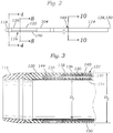
- FIG. 1 illustrates a representative embodiment of a delivery apparatus 100 including a handle portion 102 and a shaft configured as a steerable guide sheath 104.
- the delivery apparatus 100 can be used to perform any diagnostic, therapeutic, or interventional procedure where access to a target location inside the body of a patient is desired.
- the delivery apparatus 100 can be used to deliver and deploy a prosthetic device in the body, to deliver tools to a target location in the body, or to deliver or introduce drugs or other agents, to name a few exemplary uses.
- the delivery apparatus can include one or more catheters coaxially disposed within and movable relative to the guide sheath 104.
- the delivery apparatus includes an intermediate catheter configured as a steerable catheter 106 disposed within the guide sheath 104, and an inner catheter configured as a delivery or implant catheter 108 coaxially disposed within the steerable catheter 106.
- the implant catheter 108 can have a prosthetic device 110 mounted on a distal end of the implant catheter in a radially compressed state.
- the prosthetic device 110 is a prosthetic heart valve mounted on an inflatable balloon 112 at the distal end of the implant catheter, and the delivery apparatus can be configured to deliver the prosthetic heart valve 110 to one of the native valves of the heart (the aortic, mitral, pulmonary, or tricuspid valves).
- the native valves of the heart the aortic, mitral, pulmonary, or tricuspid valves.
- the prosthetic heart valve 110 can be a plastically-expandable prosthetic heart valve, and the inflatable balloon 112 can be configured to expand and deploy the valve 110 at a treatment site.
- Exemplary configurations of the balloon 112 and implant catheter 108 are further disclosed in U.S. Patent Application Publication Nos. 2013/0030519 , 2009/0281619 , 2008/0065011 , and 2007/0005131 .
- Exemplary plastically-expandable prosthetic heart valves are disclosed in U.S. Patent Application Publication Nos. 2010/0036484 and 2012/0123529 .
- the delivery apparatus 100 can be used to deliver and deploy a self-expandable prosthetic heart valve (e.g., a prosthetic valve having a frame formed from a shape-memory material, such as nitinol).
- a self-expandable prosthetic heart valve e.g., a prosthetic valve having a frame formed from a shape-memory material, such as nitinol.
- the prosthetic valve can be loaded into a delivery sheath or sleeve in a radially compressed state and advanced from the distal open end of the sheath at the target location to allow the prosthetic valve to expand to its functional size.
- the delivery sheath can be the distal end portion of the implant catheter 108, or the distal end portion of another shaft that extends through the guide sheath 104.
- the steerable guide sheath 104 can include a proximal portion 114 coupled to the handle portion 102, and a distal portion 116.
- the distal portion 116 can include low durometer atraumatic tip portion 118 coupled to a coupling portion 120 positioned proximally of the atraumatic tip 118.
- the atraumatic tip 118 can be radiopaque.
- the distal portion 114 of the guide sheath 104 can include a steerable portion 122 located proximally of the coupling portion 120 and configured to flex and unflex to adjust the curvature of the distal portion of the guide sheath, as described in detail below.
- FIGS. 3-10 illustrate the construction of the guide sheath 104, and particularly of the distal portion 116, in greater detail.
- the curvature of the guide sheath 104 can be controlled by one or more eccentrically-positioned pull wires (see, e.g., FIGS. 3 , 5 , and 8 ).
- the guide sheath 104 includes two pull wires 124, 126 extending longitudinally through respective pull-wire lumens or conduits 128, 130.
- the assembled pull wires 124, 126 and conduits 128, 130 can be disposed in a pull-wire conduit portion 154 of the guide sheath.
- the pull-wire conduit portion 154 is at least partially defined by a recess 142 of an inner layer 134 of the guide sheath.
- the recess 142 can extend into an inner diameter Di of the guide sheath 104, although other configurations are possible.
- the pull-wire conduits 128, 130 can be made from a lubricious material, such as polytetrafluoroethylene (PTFE) to reduce friction between the pull wires 124, 126 and the respective conduits 128, 130 as the pull wires move within the conduits.
- PTFE polytetrafluoroethylene
- the pull wires 124, 126 can be coupled at one end to a pull ring 144 embedded in the coupling portion 120, and coupled at the opposite end to a control mechanism configured as a rotatable knob 132 of the handle 102 (see FIG. 1 ). Rotation of the knob 132 can increase and decrease tension in the pull wires 124, 126 which, in turn, can cause the distal portion 116, and particularly the steerable portion 122, to flex and unflex to control the curvature of the guide sheath.
- a cross-sectional view of the coupling portion 122 illustrating the pull ring 144 encapsulated in the coupling portion is shown in FIG. 4 .
- the pull ring 144 and the distal portions of the pull wires 124, 126 are shown in isolation in FIG. 5 .
- the pull ring 144 can define a plurality of openings 156 about its circumference.
- the polymeric material of the coupling portion 120 can be reflowed over the pull ring 144, and the material can flow through the openings 156 to encapsulate the pull ring in the coupling portion, as shown in FIG. 3 .
- the illustrated embodiment includes two pull wires 124, 126, it should be understood that other configurations are possible (not claimed).
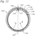
- the guide sheath 104 can include any suitable number of pull wires having any suitable size or layout, including a single pull wire (see FIG. 12 ), or more than two pull wires, depending upon the requirements of the device.
- the particular embodiment illustrated herein includes two pull wires because, in some configurations, two pull wires can occupy a smaller cross-sectional area than that of a single larger pull wire for transmitting a given force to the pull ring 144, particularly when relatively large forces are required (such as when flexing the guide sheath loaded with the steerable catheter 106 and the implant catheter 108).
- the guide sheath 104 can include a plurality of layers comprising a variety of different materials at different locations along the length of the guide sheath and configured to impart various properties to the guide sheath.
- the steerable portion 122 of the guide sheath 104 comprises a first inner layer 134 defining an inner diameter Di of the guide sheath 104, and a second pull-wire conduit encapsulating layer 135 disposed radially outward of the inner layer 134.
- a third helically coiled layer 136 extends over the pull-wire conduit encapsulating layer 135.
- a fourth braided layer 138 is disposed over the helically coiled layer 136, and a fifth outer layer 140 is disposed over the braided layer, and defines an outer diameter D 2 of the guide sheath.
- FIG. 6 illustrates a plan view of the distal portion 116 of the guide sheath 104 with each of the outer layer 140, the braided layer 138, the helically coiled layer 136, and the pull-wire conduit encapsulating layer 135 shown partially removed to illustrate the construction of the guide sheath.
- the first layer 134 extends along the full length of the guide sheath 104, and can be made from (or coated with) a lubricious material (e.g., PTFE) to allow the steerable intermediate catheter 106 to slide relative to the guide sheath 104 within the guide sheath's lumen. As stated above, the first layer 134 can also define the recess 142 of the pull-wire conduit portion 154 in which the pull wires 124, 126 and conduits 128, 130 are received.
- a lubricious material e.g., PTFE
- the pull-wire conduit encapsulating layer 135 can be disposed between the first inner layer 134 and the helically coiled layer 136, and can have a thickness that varies angularly around the circumference of the guide sheath.
- the portion of the pull-wire conduit encapsulating layer 135 proximate the pull-wire conduit portion 154 can be sufficiently thick such that the layer 135 encapsulates the pull-wire conduits 128, 130 in the pull-wire conduit portion. Meanwhile, the portion of the pull-wire conduit encapsulating layer 135 opposite the pull-wire conduit portion 154 can be relatively thin.
- the pull-wire conduit encapsulating layer 135 can extend around only a portion of the cross-section of the guide sheath, such as around the portion (e.g., half) including the pull-wire conduits 128, 130.
- the helically coiled layer 136 can directly contact the inner layer 134 along the portion of the inner layer's cross-section that is opposite the pull-wire conduits, and can transition over the pull-wire conduit encapsulating layer 135 at the location along the circumference of the inner layer 134 where the pull-wire conduit encapsulating layer originates.
- the pull-wire conduit encapsulating layer 135 can be made from any suitable polymer, such as any of various polyether block amides (e.g., Pebax®). In certain configurations, the pull-wire conduit encapsulating layer 135 can extend from the proximal end of the coupling portion 120, through the steerable portion 122, to the pull wire exit 148 ( FIG. 2 ).
- any suitable polymer such as any of various polyether block amides (e.g., Pebax®).
- the pull-wire conduit encapsulating layer 135 can extend from the proximal end of the coupling portion 120, through the steerable portion 122, to the pull wire exit 148 ( FIG. 2 ).
- the helically coiled layer 136 can be formed from, for example, a wire helically wrapped or wound about the pull-wire conduit encapsulating layer 135 or the first layer 134.
- the helically coiled layer 136 can extend from adjacent the pull ring 144 proximally through the coupling portion 120 and the steerable portion 122 to a transition region 146 ( FIG. 1 ) located between the proximal and distal portions 114, 116.
- the transition region 146 where the helically coiled layer 136 ends can be the location at which the outer layer 140 changes from a material having a relatively higher durometer or hardness (e.g., 63D Pebax®) to a material having a relatively lower durometer (e.g., a polyamide such as VESTAMID®).
- a material having a relatively higher durometer or hardness e.g., 63D Pebax®
- a material having a relatively lower durometer e.g., a polyamide such as VESTAMID®
- gradually varying (e.g., stepwise) the hardness of the outer layer 140 or the other layers of the shaft along their length can reduce the likelihood of kinking, fracture, or warping of the shaft during flexing, or when traversing vessels of the body.
- the helically coiled layer 136 can be made from stainless steel or titanium flat wire wound at, for example, 50 coils per 2,54 cm (1 inch) with a pitch of 0,0508 cm (0.020 inch), and can be configured to resist kinking or crushing of the guide shaft 104, and particularly of the steerable portion 122, when it is flexed.
- the braided layer 138 can extend over the helically coiled layer 136.
- the braided layer 138 can extend from the coupling portion 120 proximate the pull ring 144 proximally to, for example, the pull wire exit 148.
- the braided layer 138 can be, for example, metal wires braided together in a pattern to form a tubular layer over the helically coiled layer 136.
- the braided layer 138 is made from stainless steel or titanium flat wires braided in an over 1 under 1 pattern, although any suitable braid pattern can be used.
- the wires of the braided layer 138 can be braided in a 1 over 2, under 2 pattern with a pick count of 60 picks per 2,54 cm (1 inch) (PPI).
- the braided layer 138 can be configured to, for example, resist undesirable torsional deformation of the guide sheath 104 to allow the guide sheath to transmit torque, which can aid in positioning the implant at the treatment site.
- the braided layer 138 can also provide crush or kink-resistance properties to the guide sheath 104.
- the coupling portion 120 can also include a braided layer 158 disposed beneath the pull ring 144, as shown in FIGS. 3 and 4 .
- the outer layer 140 can comprise, for example, any of a variety of polymeric materials such as polyamides (e.g., VESTAMID®), polyether block amides (e.g., Pebax®), nylon, or any other suitable biocompatible polymer or combinations thereof along its length.
- polyamides e.g., VESTAMID®
- polyether block amides e.g., Pebax®
- nylon or any other suitable biocompatible polymer or combinations thereof along its length.
- the pull-wire conduit encapsulating layer 135, the helically coiled layer 136, and the braided layer 138 can terminate distally of the proximal end of the guide sheath 104.
- these layers can terminate at the pull wire exit 148.
- the outer layer 140 can increase in thickness to maintain a substantially uniform outer diameter along the length of the guide sheath, as illustrated in FIG. 10 .
- the distal portion 116 of the guide sheath 104 can include a compression-resistance portion 150.
- the compression-resistance portion 150 is incorporated into the outer layer 140, and forms a respective part of the steerable section 122.
- the compression-resistance portion 150 can extend along a length L of the steerable portion 122.
- the compression-resistance portion 150 can also extend circumferentially or angularly along, or occupy a respective portion of, the cross-section of the outer layer 140. For example, with reference to FIG.
- the angular extent of the compression-resistance portion 150 along the cross-section of the outer layer 140 is denoted by the angle ⁇ .
- the angle ⁇ can be from 10 degrees to 180 degrees (or half of the circumference of the cross-section). In some embodiments, the angle ⁇ can be from 10 degrees to 90 degrees. In the embodiment of FIG. 8 , the angle ⁇ is 60 degrees.
- the compression-resistance portion 150 can be disposed opposite the pull wire conduits 128, 130.
- the compression-resistance portion 150 is angularly offset from the pull wire conduit portion 154 by 180 degrees such that it is located diametrically opposite the pull wire conduits 128, 130.
- a plane 152 that bisects the pull wire conduit portion 154 also bisects the compression-resistance portion 150, as shown in FIG. 8 .
- the plane 152 bisecting the pull-wire conduit portion 154 passes between the respective conduits 128, 130.
- configurations including a single pull wire such as the alternative configuration illustrated in FIG.
- a single pull wire 160 and conduit 162 can be coaxially aligned with the pull-wire conduit portion 154 such that the plane 152 bisecting the pull-wire conduit portion 154 and the compression-resistance portion 150 also bisects the pull wire 160 and the conduit 162.
- the compression-resistance portion 150 can be angularly offset from the pull-wire conduit portion 154 along the cross-section of the outer layer 140 by, for example, from 90 degrees to 180 degrees, as desired.
- the compression-resistance portion 150 can be made from a material having a relatively higher hardness or durometer than the remainder of the outer layer 140 in the steerable portion 122 in which the compression-resistance portion is incorporated.
- the compression-resistance portion 150 can have a durometer that is from 1.5 times to 5 times greater than a durometer of the remainder of the outer layer 140 in the steerable portion 122.
- the durometer of the compression-resistance portion 150 can be from 2 times to 3 times greater than the durometer of the remainder of the outer layer 140 in the steerable portion 122.
- the compression-resistance portion 150 can be made from PEBAX® having a durometer of 72D, and the remainder of the outer layer 140 of the steerable portion 122 can be made from PEBAX® having a durometer of 25D, such that a ratio of the durometer of the compression-resistance portion 150 and the durometer of the remainder of the outer layer 140 in the steerable portion 122 is 2.9:1. In some embodiments, the ratio of the durometer of the compression-resistance portion 150 to the durometer of the remainder of the outer layer 140 in the steerable portion 122 can be 3:1.
- the compression-resistance portion 150 can be made of any of various materials exhibiting suitable hardness properties, including metals such as stainless steel, titanium, nickel titanium alloys such as nitinol, cobalt chromium, or other polymers.
- the compression-resistance portion need not have a thickness equal to the overall thickness of the outer layer 140.
- the compression-resistance portion 150 can have a thickness that is less than the overall thickness of the outer layer, and may be encapsulated within the outer layer, as desired.
- the durometer of the compression-resistance portion 150 can also vary along its length.
- the proximal portion of the compression-resistance portion 150 can have a relatively lower durometer than the distal portion, or vice versa.
- the compression-resistance portion 150 can provide a variety of advantageous characteristics to the steerable portion 122 of the guide sheath 104.
- the relatively higher durometer of the compression-resistance portion 150 can provide axial strength to the steerable portion 122. This can significantly reduce or prevent undesirable foreshortening of the guide sheath 104, and particularly of the steerable portion 122, when the guide catheter is flexed.
- the compression-resistance portion 150 can reduce axial compression of the guide sheath and associated wrinkling of the material when the guide sheath is flexed compared to when it is in a non-deflected state.
- Such axial compression and wrinkling of the material can decrease the length of the guide sheath 104 as the material is deformed, and can damage the guide sheath.
- the compression-resistance portion 150 can reduce the need for the operator to longitudinally reposition the delivery apparatus (e.g., by advancing or retracting the delivery apparatus through the patient's vasculature) in order to obtain or regain a desired position of the implant at the treatment site after flexing the guide sheath.
- the location of the compression-resistance portion 150 angularly offset from the pull wire conduits 128, 130 can aid in initiating deformation of the steerable portion 122 of the guide sheath in a specified direction.
- the axial stiffness of the compression-resistance portion can induce deflection of the steerable portion 122 in a direction away from the compression-resistance portion when the guide sheath is flexed, as illustrated in FIG. 11 .
- the compression-resistance portion 150 can also reduce or prevent ovalizing (also referred to as "pancaking") of the guide sheath by reducing longitudinal movement of the different layers of the sheath relative to one another when the sheath is flexed, especially in cases in which one or more constituent layers (e.g., PTFE layers such as inner layer 134) are not strongly adhered to the surrounding layer(s).
- ovalizing also referred to as "pancaking”
- the compression-resistance portion 150 can also increase the degree of flexion of the distal portion 116 attainable for a given force applied to the distal portion by the pull wires 124, 126, without damaging the guide sheath.
- the angle of flexion of the distal portion 116 is denoted ⁇ , and is illustrated in FIG. 11 .
- ⁇ The angle of flexion of the distal portion 116
- a greater proportion of the force applied by the pull wires 124, 126 is available to flex the guide sheath instead of elastically compressing the guide sheath.
- the compression-resistance portion 150 can reduce or prevent slackening of the pull wires 124, 126 attendant to foreshortening of the guide sheath 104 when it is flexed, resulting in a greater degree of curvature attainable for a given pull wire travel as compared to typical guide sheaths.
- pull wire travel refers to the linear distance that a given point along the length of a pull wire moves with respect to a stationary reference (e.g., a pull wire conduit) when tension is applied to the pull wire.
- the compression-resistance portion 150 can provide significant synergistic advantages that improve the performance of the guide sheath 104 over known steerable sheaths and catheters.
- the distal portion of an unloaded guide sheath e.g., a guide sheath without a delivery catheter or other shaft extending through its lumen
- having an inner diameter of 22 Fr having an inner diameter of 22 Fr and including the compression-resistance portion, helically coiled layer, and braided layer features is capable of flexing nearly 355 degrees without kinking, and without significant foreshortening, under a force of 175 N applied by the pull wires.
- the distal portion of a guide sheath having an inner diameter of 22 Fr and including the above compression-resistance portion, helically coiled layer, and braided layer features, and loaded with a delivery catheter and an implant catheter extending coaxially within the lumen of the guide sheath was capable of flexing 270 degrees without kinking, and without significant foreshortening, under a force of 250 N applied by the pull wires.
- 40 mm of pull wire travel were required to apply a force of 250 N to the distal portion of the guide sheath.
- a force of 250 N produces 180 degrees of flexure and requires 70 mm of pull wire travel, and the guide sheath can be expected to foreshorten by 6 mm to 10 mm.
- the delivery apparatus 100 can be introduced and advanced through the patient's vasculature using any known delivery technique.
- the delivery apparatus can be inserted through a femoral artery and the aorta to access the heart (typically, but not exclusively used for aortic valve replacement).
- the delivery device can be advanced to the right atrium, such as via a femoral vein, and through the septum separating the right and left ventricles.
- the disclosed delivery apparatuses can be particularly useful for delivering a prosthetic valve to the native mitral valve, as the torqueability of the guide sheath 104 and the relatively high degree of curvature achievable with the distal portion 116 allows for precise positioning of the prosthetic valve at the target site despite the tortuous pathway the delivery apparatus must follow to access the mitral valve in some approaches.
- the delivery apparatus can be inserted through a surgical incision made on the bare spot on the lower anterior ventricle wall (typically, but not exclusively used for aortic or mitral valve replacement).
- the delivery apparatus In a transatrial procedure, the delivery apparatus can be inserted through a surgical incision made in the wall of the left or right atrium.
- the delivery apparatus In a transaortic procedure, the delivery apparatus can be inserted through a surgical incision made in the ascending aorta and advanced toward the heart (typically, but not exclusively used for aortic valve replacement).
- the combination of the compression-resistance portion 150, the helically coiled layer 136, and the braided layer 138 can aid in precisely positioning a prosthetic device, such as the heart valve 110, at a treatment site.
- a prosthetic device such as the heart valve 110
- the distal portion 116 of the guide sheath 104 can be flexed to axially align the prosthetic valve 110 with the mitral valve (e.g., 180 degrees or more, in certain examples).
- the guide sheath 104 can also be torqued to radially position the prosthetic valve 110 with respect to the mitral valve.
- the combination of the compression-resistance portion 150, the helically coiled layer 136, and the braided layer 138 can allow the guide sheath to flex without significant foreshortening or kinking, and to be torqued without undesirable torsional deformation of the shaft or associated unpredictable rotational motion of the guide sheath.
- the components of the disclosed delivery apparatuses can be rearranged.
- the locations of the helically coiled layer 136 and the braided layer 138 can be reversed such that the helically coiled layer is on top of the braided layer.
- the helically coiled layer 136 and the braided layer 138 can be separated from one another by one or more intermediate layers.
- the compression-resistance portion 150 need not be a respective portion of the outer layer 140, but can be incorporated into any suitable layer in the guide sheath 104.
- the compression-resistance portion 150 also need not extend along the entire length of the steerable portion 122, but can extend along any suitable portion of the steerable portion.
- the disclosed compression-resistance portion, helically coiled layer, and braided layer features described herein can also be applicable to other types of steerable catheter devices, such as delivery catheters.
- the singular forms “a,” “an,” and “the” include the plural forms unless the context clearly dictates otherwise. Additionally, the term “includes” means “comprises.” Further, the terms “coupled” and “associated” generally mean electrically, electromagnetically, or physically ( e.g ., mechanically or chemically) coupled or linked and does not exclude the presence of intermediate elements between the coupled or associated items absent specific contrary language.
- the terms “lower” and “upper” are used interchangeably with the terms “inflow” and “outflow”, respectively.
- the lower end of the valve is its inflow end and the upper end of the valve is its outflow end.
- proximal refers to a position, direction, or portion of a device that is closer to the user and further away from the implantation site.
- distal refers to a position, direction, or portion of a device that is further away from the user and closer to the implantation site.
- proximal motion of a device is motion of the device toward the user
- distal motion of the device is motion of the device away from the user.
- longitudinal and axial refer to an axis extending in the proximal and distal directions, unless otherwise expressly defined.
Claims (9)
- Zuführvorrichtung (100), umfassend:einen lenkbaren Schaft (104) mit einem proximalen Abschnitt (114), einem distalen Abschnitt (116) und einem ersten Zugdrahtkanal (128) und einem zweiten Zugdrahtkanal (130), die sich jeweils zumindest teilweise durch den proximalen und den distalen Abschnitt des Schafts (104) erstrecken, wobei der zweite Zugdrahtkanal (130) benachbart zu dem ersten Zugdrahtkanal (128) angeordnet ist;einen ersten Zugdraht (124), der sich durch den ersten Zugdrahtkanal (128) erstreckt, und einen zweiten Zugdraht (126), der sich durch den zweiten Zugdrahtkanal (130) erstreckt, wobei der erste und der zweite Zugdraht (124, 126) jeweils einen distalen Endabschnitt, der an dem distalen Abschnitt des Schafts (104) befestigt ist, und einen proximalen Endabschnitt aufweisen;einen Einstellmechanismus (132), der wirksam mit dem proximalen Endabschnitt des ersten und des zweiten Zugdrahts (124, 126) verbunden ist und dafür konfiguriert ist, die Spannung im ersten und zweiten Zugdraht (124, 126) zu erhöhen und zu verringern, um die Krümmung des distalen Abschnitts (116) des Schafts (104) einzustellen;wobei der Schaft (104) eine erste innere Schicht (134), die einen Innendurchmesser des Schafts (104) definiert, und eine zweite äußere Schicht (140), die einen Außendurchmesser des Schafts (104) definiert, umfasst, wobei der distale Abschnitt des Schafts(104) einen lenkbaren Abschnitt (122) umfasst, der einen druckfesten Abschnitt (150) enthält, der sich gegenüber dem ersten und zweiten Zugdrahtkanal (128, 130) befindet und in die zweite äußere Schicht (140) des lenkbaren Abschnitts (122) integriert ist, wobei die erste innere Schicht (134) eine Aussparung (154) definiert, die dafür konfiguriert ist, den ersten und zweiten Zugdrahtkanal (128, 130) aufzunehmen, wobei sich der druckfeste Abschnitt (150) winkelmäßig entlang eines Abschnitts eines Querschnitts der zweiten äußeren Schicht (140) erstreckt, wobei die zweite äußere Schicht (140) des lenkbaren Abschnitts (122) eine erste Härte aufweist, und wobei der druckfeste Abschnitt (150) eine zweite Härte aufweist, die größer ist als die erste Härte.
- Zuführvorrichtung (100) nach Anspruch 1, wobei sich der druckfeste Abschnitt (150) von 10 Grad bis 180 Grad entlang des Querschnitts der zweiten äußeren Schicht (140) erstreckt.
- Zuführvorrichtung (100) nach Anspruch 2, wobei sich der druckfeste Abschnitt (150) über 60 Grad entlang des Querschnitts der zweiten äußeren Schicht (140) erstreckt.
- Zuführvorrichtung (100) nach einem der Ansprüche 1 bis 3, wobei der Schaft (104) ferner eine dritte schraubenlinienförmig gewundene Schicht (136) zwischen der ersten inneren Schicht (134) und der zweiten äußeren Schicht (140) umfasst.
- Zuführvorrichtung (100) nach Anspruch 4, wobei der Schaft (104) ferner eine vierte geflochtene Schicht (138) umfasst, die über mindestens einen Abschnitt der schraubenlinienförmig gewundenen Schicht (136) geflochten ist.
- Zuführvorrichtung (100) nach Anspruch 5, wobei der Schaft (104) ferner eine Zugdrahtkanal-Einkapselungsschicht (135) zwischen der ersten inneren Schicht (134) und der schraubenlinienförmig gewundenen Schicht (136) umfasst, die den ersten und zweiten Zugdrahtkanal (128, 130) einkapselt.
- Zuführvorrichtung (100) nach einem der Ansprüche 1 bis 6, wobei ein Verhältnis der zweiten Härte zur ersten Härte im Bereich 1,5:1 bis 5:1 liegt.
- Zuführvorrichtung (100) nach Anspruch 7, wobei das Verhältnis 3:1 beträgt.
- Zuführvorrichtung (100) nach einem der Ansprüche 1 bis 8, wobei der Schaft (104) eine Führungshülse ist, und die Zuführvorrichtung (100) ferner einen Implantatkatheter enthält, der koaxial innerhalb der Führungshülse angeordnet ist und eine prothetische Klappe aufweist, die an einem distalen Ende des Implantatkatheters angebracht ist.
Priority Applications (1)
| Application Number | Priority Date | Filing Date | Title |
|---|---|---|---|
| EP21163841.6A EP3871729A1 (de) | 2016-11-07 | 2017-11-07 | Vorrichtung zur einführung und manipulation von mehreren teleskopischen kathetern |
Applications Claiming Priority (3)
| Application Number | Priority Date | Filing Date | Title |
|---|---|---|---|
| US201662418528P | 2016-11-07 | 2016-11-07 | |
| US15/796,436 US10653862B2 (en) | 2016-11-07 | 2017-10-27 | Apparatus for the introduction and manipulation of multiple telescoping catheters |
| PCT/US2017/060336 WO2018085812A1 (en) | 2016-11-07 | 2017-11-07 | Apparatus for the introduction and manipulation of multiple telescoping catheters |
Related Child Applications (1)
| Application Number | Title | Priority Date | Filing Date |
|---|---|---|---|
| EP21163841.6A Division EP3871729A1 (de) | 2016-11-07 | 2017-11-07 | Vorrichtung zur einführung und manipulation von mehreren teleskopischen kathetern |
Publications (3)
| Publication Number | Publication Date |
|---|---|
| EP3535010A1 EP3535010A1 (de) | 2019-09-11 |
| EP3535010A4 EP3535010A4 (de) | 2019-12-04 |
| EP3535010B1 true EP3535010B1 (de) | 2021-03-24 |
Family
ID=62065913
Family Applications (2)
| Application Number | Title | Priority Date | Filing Date |
|---|---|---|---|
| EP17866608.7A Active EP3535010B1 (de) | 2016-11-07 | 2017-11-07 | Vorrichtung zur einführung und manipulation von mehreren teleskopischen kathetern |
| EP21163841.6A Pending EP3871729A1 (de) | 2016-11-07 | 2017-11-07 | Vorrichtung zur einführung und manipulation von mehreren teleskopischen kathetern |
Family Applications After (1)
| Application Number | Title | Priority Date | Filing Date |
|---|---|---|---|
| EP21163841.6A Pending EP3871729A1 (de) | 2016-11-07 | 2017-11-07 | Vorrichtung zur einführung und manipulation von mehreren teleskopischen kathetern |
Country Status (5)
| Country | Link |
|---|---|
| US (3) | US10653862B2 (de) |
| EP (2) | EP3535010B1 (de) |
| JP (2) | JP7015831B2 (de) |
| CN (1) | CN109906099A (de) |
| WO (1) | WO2018085812A1 (de) |
Families Citing this family (66)
| Publication number | Priority date | Publication date | Assignee | Title |
|---|---|---|---|---|
| US8652202B2 (en) | 2008-08-22 | 2014-02-18 | Edwards Lifesciences Corporation | Prosthetic heart valve and delivery apparatus |
| US8449599B2 (en) | 2009-12-04 | 2013-05-28 | Edwards Lifesciences Corporation | Prosthetic valve for replacing mitral valve |
| US8579964B2 (en) | 2010-05-05 | 2013-11-12 | Neovasc Inc. | Transcatheter mitral valve prosthesis |
| US9308087B2 (en) | 2011-04-28 | 2016-04-12 | Neovasc Tiara Inc. | Sequentially deployed transcatheter mitral valve prosthesis |
| US9554897B2 (en) | 2011-04-28 | 2017-01-31 | Neovasc Tiara Inc. | Methods and apparatus for engaging a valve prosthesis with tissue |
| US9345573B2 (en) | 2012-05-30 | 2016-05-24 | Neovasc Tiara Inc. | Methods and apparatus for loading a prosthesis onto a delivery system |
| US9572665B2 (en) | 2013-04-04 | 2017-02-21 | Neovasc Tiara Inc. | Methods and apparatus for delivering a prosthetic valve to a beating heart |
| WO2016090308A1 (en) | 2014-12-04 | 2016-06-09 | Edwards Lifesciences Corporation | Percutaneous clip for repairing a heart valve |
| CN110433010A (zh) | 2015-05-14 | 2019-11-12 | 爱德华兹生命科学公司 | 心脏瓣膜密封装置及其递送装置 |
| CN113633435A (zh) | 2016-01-29 | 2021-11-12 | 内奥瓦斯克迪亚拉公司 | 用于防止流出阻塞的假体瓣膜 |
| US10799676B2 (en) | 2016-03-21 | 2020-10-13 | Edwards Lifesciences Corporation | Multi-direction steerable handles for steering catheters |
| US11219746B2 (en) | 2016-03-21 | 2022-01-11 | Edwards Lifesciences Corporation | Multi-direction steerable handles for steering catheters |
| US10799677B2 (en) | 2016-03-21 | 2020-10-13 | Edwards Lifesciences Corporation | Multi-direction steerable handles for steering catheters |
| US10835714B2 (en) | 2016-03-21 | 2020-11-17 | Edwards Lifesciences Corporation | Multi-direction steerable handles for steering catheters |
| US10799675B2 (en) | 2016-03-21 | 2020-10-13 | Edwards Lifesciences Corporation | Cam controlled multi-direction steerable handles |
| US10973638B2 (en) | 2016-07-07 | 2021-04-13 | Edwards Lifesciences Corporation | Device and method for treating vascular insufficiency |
| US10653862B2 (en) * | 2016-11-07 | 2020-05-19 | Edwards Lifesciences Corporation | Apparatus for the introduction and manipulation of multiple telescoping catheters |
| CN113893064A (zh) | 2016-11-21 | 2022-01-07 | 内奥瓦斯克迪亚拉公司 | 用于快速收回经导管心脏瓣膜递送系统的方法和系统 |
| US10905554B2 (en) | 2017-01-05 | 2021-02-02 | Edwards Lifesciences Corporation | Heart valve coaptation device |
| LT3558169T (lt) | 2017-04-18 | 2022-02-10 | Edwards Lifesciences Corporation | Širdies vožtuvo sandarinimo įrenginiai ir jų perdavimo įtaisai |
| US11224511B2 (en) | 2017-04-18 | 2022-01-18 | Edwards Lifesciences Corporation | Heart valve sealing devices and delivery devices therefor |
| US10799312B2 (en) | 2017-04-28 | 2020-10-13 | Edwards Lifesciences Corporation | Medical device stabilizing apparatus and method of use |
| US10959846B2 (en) | 2017-05-10 | 2021-03-30 | Edwards Lifesciences Corporation | Mitral valve spacer device |
| CA3073834A1 (en) | 2017-08-25 | 2019-02-28 | Neovasc Tiara Inc. | Sequentially deployed transcatheter mitral valve prosthesis |
| US11051940B2 (en) | 2017-09-07 | 2021-07-06 | Edwards Lifesciences Corporation | Prosthetic spacer device for heart valve |
| US11065117B2 (en) | 2017-09-08 | 2021-07-20 | Edwards Lifesciences Corporation | Axisymmetric adjustable device for treating mitral regurgitation |
| US11040174B2 (en) | 2017-09-19 | 2021-06-22 | Edwards Lifesciences Corporation | Multi-direction steerable handles for steering catheters |
| US10973639B2 (en) | 2018-01-09 | 2021-04-13 | Edwards Lifesciences Corporation | Native valve repair devices and procedures |
| US10245144B1 (en) | 2018-01-09 | 2019-04-02 | Edwards Lifesciences Corporation | Native valve repair devices and procedures |
| US10076415B1 (en) | 2018-01-09 | 2018-09-18 | Edwards Lifesciences Corporation | Native valve repair devices and procedures |
| US10238493B1 (en) | 2018-01-09 | 2019-03-26 | Edwards Lifesciences Corporation | Native valve repair devices and procedures |
| US10111751B1 (en) | 2018-01-09 | 2018-10-30 | Edwards Lifesciences Corporation | Native valve repair devices and procedures |
| US10123873B1 (en) | 2018-01-09 | 2018-11-13 | Edwards Lifesciences Corporation | Native valve repair devices and procedures |
| US10231837B1 (en) | 2018-01-09 | 2019-03-19 | Edwards Lifesciences Corporation | Native valve repair devices and procedures |
| US10136993B1 (en) | 2018-01-09 | 2018-11-27 | Edwards Lifesciences Corporation | Native valve repair devices and procedures |
| US10507109B2 (en) | 2018-01-09 | 2019-12-17 | Edwards Lifesciences Corporation | Native valve repair devices and procedures |
| US10159570B1 (en) | 2018-01-09 | 2018-12-25 | Edwards Lifesciences Corporation | Native valve repair devices and procedures |
| SG11202006509SA (en) | 2018-01-09 | 2020-08-28 | Edwards Lifesciences Corp | Native valve repair devices and procedures |
| WO2019147504A1 (en) * | 2018-01-25 | 2019-08-01 | Cephea Valve Technologies, Inc. | Cardiac valve delivery devices and systems |
| US11389297B2 (en) | 2018-04-12 | 2022-07-19 | Edwards Lifesciences Corporation | Mitral valve spacer device |
| US11207181B2 (en) | 2018-04-18 | 2021-12-28 | Edwards Lifesciences Corporation | Heart valve sealing devices and delivery devices therefor |
| US10953195B2 (en) | 2018-06-01 | 2021-03-23 | Covidien Lp | Flexible tip catheter |
| CN110575285A (zh) * | 2018-06-08 | 2019-12-17 | 上海微创心通医疗科技有限公司 | 植入物输送管件和植入物输送系统 |
| US10945844B2 (en) | 2018-10-10 | 2021-03-16 | Edwards Lifesciences Corporation | Heart valve sealing devices and delivery devices therefor |
| AU2019374743B2 (en) | 2018-11-08 | 2022-03-03 | Neovasc Tiara Inc. | Ventricular deployment of a transcatheter mitral valve prosthesis |
| EP4223258A1 (de) | 2019-02-14 | 2023-08-09 | Edwards Lifesciences Corporation | Herzklappenverschlussvorrichtungen und freisetzungsvorrichtungen dafür |
| US11602429B2 (en) | 2019-04-01 | 2023-03-14 | Neovasc Tiara Inc. | Controllably deployable prosthetic valve |
| WO2020210652A1 (en) | 2019-04-10 | 2020-10-15 | Neovasc Tiara Inc. | Prosthetic valve with natural blood flow |
| CA3140925A1 (en) | 2019-05-20 | 2020-11-26 | Neovasc Tiara Inc. | Introducer with hemostasis mechanism |
| AU2020295566B2 (en) | 2019-06-20 | 2023-07-20 | Neovasc Tiara Inc. | Low profile prosthetic mitral valve |
| EP3993736B1 (de) | 2019-07-02 | 2023-11-15 | Edwards Lifesciences Corporation | Herzklappenprothese und freisetzungsvorrichtung dafür |
| US11524139B2 (en) | 2019-07-15 | 2022-12-13 | Medtronic, Inc. | Catheter with active return curve |
| US11524143B2 (en) * | 2019-07-15 | 2022-12-13 | Medtronic, Inc. | Catheter with distal and proximal fixation members |
| CN113473946A (zh) * | 2019-08-13 | 2021-10-01 | 美利奴生命科学有限公司 | 人工心脏瓣膜组件 |
| US20210220626A1 (en) | 2019-08-14 | 2021-07-22 | Vasoinnovations, Inc. | Apparatus and method for advancing catheters or other medical devices through a lumen |
| US10828470B1 (en) | 2019-08-14 | 2020-11-10 | Vasoinnovations Inc. | Apparatus and method for advancing catheters or other medical devices through a lumen |
| US10792469B1 (en) | 2019-08-14 | 2020-10-06 | Vasoinnovations Inc. | Devices, systems, and methods for delivering catheters or other medical devices to locations within a patients body |
| USD940306S1 (en) * | 2020-06-11 | 2022-01-04 | Oscor Inc. | Steerable catheter handle |
| USD940307S1 (en) * | 2020-06-11 | 2022-01-04 | Oscor Inc. | Steerable catheter handle |
| WO2021258113A1 (en) | 2020-06-19 | 2021-12-23 | Remedy Robotics, Inc. | Systems and methods for guidance of intraluminal devices within the vasculature |
| US11969343B2 (en) | 2020-12-07 | 2024-04-30 | Medtronic, Inc. | Transcatheter heart valve prosthesis systems and methods for rotational alignment |
| CA3217020A1 (en) | 2021-04-28 | 2022-11-03 | Edwards Lifesciences Corporation | Delivery devices for heart valve treatment devices |
| US11707332B2 (en) | 2021-07-01 | 2023-07-25 | Remedy Robotics, Inc. | Image space control for endovascular tools |
| CA3222522A1 (en) | 2021-07-01 | 2023-01-05 | David James Bell | Vision-based position and orientation determination for endovascular tools |
| WO2023146859A1 (en) | 2022-01-26 | 2023-08-03 | Edwards Lifesciences Corporation | Delivery devices for heart valve repair and replacement devices |
| WO2023167825A1 (en) | 2022-03-02 | 2023-09-07 | Edwards Lifesciences Corporation | Heart valve repair devices and delivery devices therefor |
Family Cites Families (426)
| Publication number | Priority date | Publication date | Assignee | Title |
|---|---|---|---|---|
| FR971600A (fr) | 1948-09-13 | 1951-01-18 | Bande de couverture pour toits et de revêtement mural, et machine pour l'exécution de cette bande | |
| DE2232914A1 (de) | 1971-07-12 | 1973-02-08 | Jeanette Lois Rubricius | Chirurgische klemme |
| US3874388A (en) | 1973-02-12 | 1975-04-01 | Ochsner Med Found Alton | Shunt defect closure system |
| US4340091A (en) | 1975-05-07 | 1982-07-20 | Albany International Corp. | Elastomeric sheet materials for heart valve and other prosthetic implants |
| JPS5936A (ja) | 1982-06-24 | 1984-01-05 | オリンパス光学工業株式会社 | 内視鏡の可撓管 |
| US4506669A (en) | 1982-09-22 | 1985-03-26 | Blake Joseph W Iii | Skin approximator |
| US4693248A (en) | 1983-06-20 | 1987-09-15 | Ethicon, Inc. | Two-piece tissue fastener with deformable retaining receiver |
| US4590937A (en) | 1985-01-07 | 1986-05-27 | American Cyanamid Company | Nonmetallic surgical clip |
| US5125895A (en) | 1986-07-22 | 1992-06-30 | Medtronic Versaflex, Inc. | Steerable catheter |
| US4803983A (en) | 1987-03-23 | 1989-02-14 | Siegel Irwin M | Muscle biopsy clamp |
| US5478353A (en) | 1987-05-14 | 1995-12-26 | Yoon; Inbae | Suture tie device system and method for suturing anatomical tissue proximate an opening |
| CA1330285C (en) | 1987-12-22 | 1994-06-21 | Geoffrey S. Martin | Triple lumen catheter |
| US5411552A (en) | 1990-05-18 | 1995-05-02 | Andersen; Henning R. | Valve prothesis for implantation in the body and a catheter for implanting such valve prothesis |
| CA2049123C (en) | 1990-09-13 | 2002-01-15 | David T. Green | Apparatus and method for subcuticular stapling of body tissue |
| US5611794A (en) | 1990-10-11 | 1997-03-18 | Lasersurge, Inc. | Clamp for approximating tissue sections |
| US5171252A (en) | 1991-02-05 | 1992-12-15 | Friedland Thomas W | Surgical fastening clip formed of a shape memory alloy, a method of making such a clip and a method of using such a clip |
| US5231989A (en) * | 1991-02-15 | 1993-08-03 | Raychem Corporation | Steerable cannula |
| US5370685A (en) | 1991-07-16 | 1994-12-06 | Stanford Surgical Technologies, Inc. | Endovascular aortic valve replacement |
| US5363861A (en) | 1991-11-08 | 1994-11-15 | Ep Technologies, Inc. | Electrode tip assembly with variable resistance to bending |
| US5327905A (en) | 1992-02-14 | 1994-07-12 | Boaz Avitall | Biplanar deflectable catheter for arrhythmogenic tissue ablation |
| US5368564A (en) | 1992-12-23 | 1994-11-29 | Angeion Corporation | Steerable catheter |
| US6010531A (en) | 1993-02-22 | 2000-01-04 | Heartport, Inc. | Less-invasive devices and methods for cardiac valve surgery |
| US5797960A (en) | 1993-02-22 | 1998-08-25 | Stevens; John H. | Method and apparatus for thoracoscopic intracardiac procedures |
| EP0684789A1 (de) | 1993-02-22 | 1995-12-06 | Valleylab, Inc. | Verfahren und vorrichtung zum spannen von gewebe bei laparoskopischen dissektionen |
| US5389077A (en) | 1993-03-03 | 1995-02-14 | Uresil Corporation | Minimally invasive body cavity penetrating instruments |
| NL9300572A (nl) | 1993-03-31 | 1994-10-17 | Cordis Europ | Werkwijze voor het vervaardigen van een extrusieprofiel met over de lengte varierende eigenschappen en daarmee vervaardigde catheter. |
| US5450860A (en) | 1993-08-31 | 1995-09-19 | W. L. Gore & Associates, Inc. | Device for tissue repair and method for employing same |
| US5607462A (en) | 1993-09-24 | 1997-03-04 | Cardiac Pathways Corporation | Catheter assembly, catheter and multi-catheter introducer for use therewith |
| US5487746A (en) | 1994-11-23 | 1996-01-30 | Yu; George W. | Surgical clip having a longitudinal opening through which clamped tissue protrudes |
| US5609598A (en) | 1994-12-30 | 1997-03-11 | Vnus Medical Technologies, Inc. | Method and apparatus for minimally invasive treatment of chronic venous insufficiency |
| US5695504A (en) | 1995-02-24 | 1997-12-09 | Heartport, Inc. | Devices and methods for performing a vascular anastomosis |
| US5626607A (en) | 1995-04-03 | 1997-05-06 | Heartport, Inc. | Clamp assembly and method of use |
| US5888247A (en) | 1995-04-10 | 1999-03-30 | Cardiothoracic Systems, Inc | Method for coronary artery bypass |
| US5891112A (en) | 1995-04-28 | 1999-04-06 | Target Therapeutics, Inc. | High performance superelastic alloy braid reinforced catheter |
| US5565004A (en) | 1995-05-30 | 1996-10-15 | Christoudias; George C. | Christoudias twin forceps approximator |
| US5716417A (en) | 1995-06-07 | 1998-02-10 | St. Jude Medical, Inc. | Integral supporting structure for bioprosthetic heart valve |
| EP0879069B1 (de) | 1995-06-12 | 2003-08-20 | Cordis Webster, Inc. | Katheter mit einem elektrischen führungssensor |
| US5836311A (en) | 1995-09-20 | 1998-11-17 | Medtronic, Inc. | Method and apparatus for temporarily immobilizing a local area of tissue |
| CN1142351A (zh) | 1996-01-09 | 1997-02-12 | 郑宏 | 房间隔缺损闭合器 |
| US5782746A (en) | 1996-02-15 | 1998-07-21 | Wright; John T. M. | Local cardiac immobilization surgical device |
| US6182664B1 (en) | 1996-02-19 | 2001-02-06 | Edwards Lifesciences Corporation | Minimally invasive cardiac valve surgery procedure |
| US5894843A (en) | 1996-02-20 | 1999-04-20 | Cardiothoracic Systems, Inc. | Surgical method for stabilizing the beating heart during coronary artery bypass graft surgery |
| US5727569A (en) | 1996-02-20 | 1998-03-17 | Cardiothoracic Systems, Inc. | Surgical devices for imposing a negative pressure to fix the position of cardiac tissue during surgery |
| US6132370A (en) | 1996-04-26 | 2000-10-17 | Genzyme Corporation | Retractor-mounted coronary stabilizer |
| DE19627992A1 (de) | 1996-07-11 | 1998-01-22 | Storz Karl Gmbh & Co | Instrument mit zwei voneinander unabhängigen Zangenmäulern |
| US5741297A (en) | 1996-08-28 | 1998-04-21 | Simon; Morris | Daisy occluder and method for septal defect repair |
| US5921979A (en) | 1996-12-18 | 1999-07-13 | Guidant Corporation | Apparatus and method for tissue and organ stabilization |
| US5938616A (en) | 1997-01-31 | 1999-08-17 | Acuson Corporation | Steering mechanism and steering line for a catheter-mounted ultrasonic transducer |
| US5891017A (en) | 1997-01-31 | 1999-04-06 | Baxter Research Medical, Inc. | Surgical stabilizer and method for isolating and immobilizing cardiac tissue |
| US5972020A (en) | 1997-02-14 | 1999-10-26 | Cardiothoracic Systems, Inc. | Surgical instrument for cardiac valve repair on the beating heart |
| US6508825B1 (en) | 1997-02-28 | 2003-01-21 | Lumend, Inc. | Apparatus for treating vascular occlusions |
| US5885271A (en) | 1997-03-14 | 1999-03-23 | Millennium Cardiac Strategies, Inc. | Device for regional immobilization of a compliant body |
| US6017358A (en) | 1997-05-01 | 2000-01-25 | Inbae Yoon | Surgical instrument with multiple rotatably mounted offset end effectors |
| US5957835A (en) | 1997-05-16 | 1999-09-28 | Guidant Corporation | Apparatus and method for cardiac stabilization and arterial occlusion |
| US6004329A (en) | 1997-05-29 | 1999-12-21 | Baxter International Inc. | Shape-adjustable surgical implement handle |
| DE69841237D1 (de) | 1997-06-27 | 2009-11-26 | Univ Columbia | Vorrichtung zum Reparieren von Kreislaufklappen |
| FR2768324B1 (fr) | 1997-09-12 | 1999-12-10 | Jacques Seguin | Instrument chirurgical permettant, par voie percutanee, de fixer l'une a l'autre deux zones de tissu mou, normalement mutuellement distantes |
| US6120496A (en) | 1998-05-05 | 2000-09-19 | Scimed Life Systems, Inc. | Surgical method and apparatus for positioning a diagnostic or therapeutic element within the body and coupling device for use with same |
| US6086600A (en) | 1997-11-03 | 2000-07-11 | Symbiosis Corporation | Flexible endoscopic surgical instrument for invagination and fundoplication |
| US6200315B1 (en) | 1997-12-18 | 2001-03-13 | Medtronic, Inc. | Left atrium ablation catheter |
| US6193734B1 (en) | 1998-01-23 | 2001-02-27 | Heartport, Inc. | System for performing vascular anastomoses |
| US5944738A (en) | 1998-02-06 | 1999-08-31 | Aga Medical Corporation | Percutaneous catheter directed constricting occlusion device |
| US7371210B2 (en) | 1998-02-24 | 2008-05-13 | Hansen Medical, Inc. | Flexible instrument |
| US7569062B1 (en) | 1998-07-15 | 2009-08-04 | St. Jude Medical, Inc. | Mitral and tricuspid valve repair |
| US6165183A (en) | 1998-07-15 | 2000-12-26 | St. Jude Medical, Inc. | Mitral and tricuspid valve repair |
| US6468285B1 (en) | 1998-09-03 | 2002-10-22 | The Cleveland Clinic Foundation | Surgical instruments and procedures |
| US6544215B1 (en) | 1998-10-02 | 2003-04-08 | Scimed Life Systems, Inc. | Steerable device for introducing diagnostic and therapeutic apparatus into the body |
| US5980534A (en) | 1998-10-07 | 1999-11-09 | Gimpelson; Richard J. | Cervical clamp |
| WO2000040159A1 (en) | 1998-12-31 | 2000-07-13 | Yeung Teresa T | Tissue fastening devices and delivery means |
| US6193732B1 (en) | 1999-01-08 | 2001-02-27 | Cardiothoracic System | Surgical clips and apparatus and method for clip placement |
| US6709429B1 (en) * | 2000-01-19 | 2004-03-23 | Scimed Life Systems, Inc. | Intravascular catheter with multiple axial fibers |
| US6942654B1 (en) * | 2000-01-19 | 2005-09-13 | Scimed Life Systems, Inc. | Intravascular catheter with axial member |
| US6171295B1 (en) * | 1999-01-20 | 2001-01-09 | Scimed Life Systems, Inc. | Intravascular catheter with composite reinforcement |
| US7563267B2 (en) | 1999-04-09 | 2009-07-21 | Evalve, Inc. | Fixation device and methods for engaging tissue |
| US20040044350A1 (en) | 1999-04-09 | 2004-03-04 | Evalve, Inc. | Steerable access sheath and methods of use |
| US8216256B2 (en) | 1999-04-09 | 2012-07-10 | Evalve, Inc. | Detachment mechanism for implantable fixation devices |
| US7811296B2 (en) | 1999-04-09 | 2010-10-12 | Evalve, Inc. | Fixation devices for variation in engagement of tissue |
| ATE492219T1 (de) | 1999-04-09 | 2011-01-15 | Evalve Inc | Vorrichtung zur herzklappenoperation |
| US6752813B2 (en) | 1999-04-09 | 2004-06-22 | Evalve, Inc. | Methods and devices for capturing and fixing leaflets in valve repair |
| WO2000067641A1 (en) | 1999-05-11 | 2000-11-16 | Williamson Warren P Iv | Surgical clamp devices and methods especially useful in cardiac surgery |
| US6241743B1 (en) | 1999-05-13 | 2001-06-05 | Intellicardia, Inc. | Anastomosis device and method |
| US6312447B1 (en) | 1999-10-13 | 2001-11-06 | The General Hospital Corporation | Devices and methods for percutaneous mitral valve repair |
| US6626930B1 (en) | 1999-10-21 | 2003-09-30 | Edwards Lifesciences Corporation | Minimally invasive mitral valve repair method and apparatus |
| US7083628B2 (en) | 2002-09-03 | 2006-08-01 | Edwards Lifesciences Corporation | Single catheter mitral valve repair device and method for use |
| JP4940390B2 (ja) | 2000-07-14 | 2012-05-30 | クック メディカル テクノロジーズ エルエルシー | 編構造体およびコイルを有する医療装置 |
| SE0002878D0 (sv) | 2000-08-11 | 2000-08-11 | Kimblad Ola | Device and method for treatment of atrioventricular regurgitation |
| US7510572B2 (en) | 2000-09-12 | 2009-03-31 | Shlomo Gabbay | Implantation system for delivery of a heart valve prosthesis |
| US7527646B2 (en) | 2000-09-20 | 2009-05-05 | Ample Medical, Inc. | Devices, systems, and methods for retaining a native heart valve leaflet |
| WO2004030568A2 (en) | 2002-10-01 | 2004-04-15 | Ample Medical, Inc. | Device and method for repairing a native heart valve leaflet |
| US6269829B1 (en) | 2000-09-29 | 2001-08-07 | Industrial Technology Research Institute | Integrated gas meter |
| US6723038B1 (en) | 2000-10-06 | 2004-04-20 | Myocor, Inc. | Methods and devices for improving mitral valve function |
| US6508806B1 (en) | 2000-12-13 | 2003-01-21 | Advanced Cardiovascular Systems, Inc. | Catheter with multi-layer wire reinforced wall construction |
| US20020107531A1 (en) | 2001-02-06 | 2002-08-08 | Schreck Stefan G. | Method and system for tissue repair using dual catheters |
| US6537290B2 (en) | 2001-03-05 | 2003-03-25 | Edwards Lifesciences Corporation | Sealing access cannula system |
| US6837867B2 (en) | 2001-04-30 | 2005-01-04 | Biosense Webster, Inc. | Steerable catheter with reinforced tip |
| US20020173811A1 (en) | 2001-05-21 | 2002-11-21 | Hosheng Tu | Apparatus and methods for valve removal |
| US7338514B2 (en) | 2001-06-01 | 2008-03-04 | St. Jude Medical, Cardiology Division, Inc. | Closure devices, related delivery methods and tools, and related methods of use |
| FR2828263B1 (fr) | 2001-08-03 | 2007-05-11 | Philipp Bonhoeffer | Dispositif d'implantation d'un implant et procede d'implantation du dispositif |
| ATE387160T1 (de) | 2001-08-31 | 2008-03-15 | Mitral Interventions | Vorrichtung für eine herzklappenreperatur |
| US20070198038A1 (en) | 2001-12-03 | 2007-08-23 | Cohen Adam L | Microdevices for Tissue Approximation and Retention, Methods for Using, and Methods for Making |
| US7357805B2 (en) | 2001-12-13 | 2008-04-15 | Sumitomo Bakelite Company | Clip device for endoscope and clip for endoscope for use therein |
| US20030144573A1 (en) | 2001-12-19 | 2003-07-31 | Heilman Marlin S. | Back-flow limiting valve member |
| US6764510B2 (en) | 2002-01-09 | 2004-07-20 | Myocor, Inc. | Devices and methods for heart valve treatment |
| US7048754B2 (en) | 2002-03-01 | 2006-05-23 | Evalve, Inc. | Suture fasteners and methods of use |
| US6855137B2 (en) | 2002-03-07 | 2005-02-15 | Visionary Biomedical, Inc. | Catheter shaft with coextruded stiffener |
| US20070185376A1 (en) | 2002-03-11 | 2007-08-09 | Wilson Roger F | System and method for positioning a laparoscopic device |
| US7094244B2 (en) | 2002-03-26 | 2006-08-22 | Edwards Lifesciences Corporation | Sequential heart valve leaflet repair device and method of use |
| WO2003105667A2 (en) | 2002-06-12 | 2003-12-24 | Mitral Interventions, Inc. | Method and apparatus for tissue connection |
| US8348963B2 (en) | 2002-07-03 | 2013-01-08 | Hlt, Inc. | Leaflet reinforcement for regurgitant valves |
| US6969098B2 (en) | 2002-07-03 | 2005-11-29 | Illinois Tool Works Inc. | Non-elevating handle for center lift carrier |
| US8172856B2 (en) | 2002-08-02 | 2012-05-08 | Cedars-Sinai Medical Center | Methods and apparatus for atrioventricular valve repair |
| EP2319427A2 (de) | 2002-08-13 | 2011-05-11 | The General Hospital Corporation | Kardiovorrichtungen und Verfahren zur perkutanen Reparatur atrioventrikulärer Klappen |
| US20040034365A1 (en) | 2002-08-16 | 2004-02-19 | Lentz David J. | Catheter having articulation system |
| US7727247B2 (en) | 2002-08-21 | 2010-06-01 | Olympus Corporation | Living tissue ligation device |
| WO2004023976A2 (en) | 2002-09-13 | 2004-03-25 | Damage Control Surgical Technologies, Inc. | Method and apparatus for vascular and visceral clipping |
| US8454628B2 (en) | 2002-09-20 | 2013-06-04 | Syntheon, Llc | Surgical fastener aligning instrument particularly for transoral treatment of gastroesophageal reflux disease |
| DE60325634D1 (de) | 2002-10-01 | 2009-02-12 | Ample Medical Inc | Vorrichtungen und systeme zur umformung eines herzklappen-annulus |
| AU2003290979A1 (en) | 2002-11-15 | 2004-06-15 | The Government Of The United States Of America As Represented By The Secretary Of Health And Human Services | Method and device for catheter-based repair of cardiac valves |
| JP2006510457A (ja) | 2002-12-17 | 2006-03-30 | アプライド メディカル リソーシーズ コーポレイション | 外科用ステープル/クリップおよびアプライヤ |
| US6945956B2 (en) | 2002-12-23 | 2005-09-20 | Medtronic, Inc. | Steerable catheter |
| US20070156197A1 (en) | 2005-12-15 | 2007-07-05 | Cardiac Pacemakers, Inc. | Method and apparatus for improved medical device profile |
| JP4145149B2 (ja) | 2003-01-17 | 2008-09-03 | オリンパス株式会社 | 生体組織のクリップ装置 |
| US7250041B2 (en) | 2003-03-12 | 2007-07-31 | Abbott Cardiovascular Systems Inc. | Retrograde pressure regulated infusion |
| US6987995B2 (en) | 2003-03-12 | 2006-01-17 | Biosense Webster, Inc. | Multifunctional catheter handle |
| US7381210B2 (en) | 2003-03-14 | 2008-06-03 | Edwards Lifesciences Corporation | Mitral valve repair system and method for use |
| US7175656B2 (en) | 2003-04-18 | 2007-02-13 | Alexander Khairkhahan | Percutaneous transcatheter heart valve replacement |
| US20040220593A1 (en) | 2003-05-01 | 2004-11-04 | Secant Medical, Llc | Restraining clip for mitral valve repair |
| US6913614B2 (en) | 2003-05-08 | 2005-07-05 | Cardia, Inc. | Delivery system with safety tether |
| US10667823B2 (en) | 2003-05-19 | 2020-06-02 | Evalve, Inc. | Fixation devices, systems and methods for engaging tissue |
| US7972347B2 (en) | 2003-06-27 | 2011-07-05 | Surgical Security, Llc | Device for surgical repair, closure, and reconstruction |
| CA2533353A1 (en) | 2003-07-21 | 2005-02-03 | The Trustees Of The University Of Pennsylvania | Percutaneous heart valve |
| US7452363B2 (en) | 2003-09-30 | 2008-11-18 | Ethicon Endo-Surgery, Inc. | Applier for fastener for single lumen access anastomosis |
| US7824443B2 (en) | 2003-12-23 | 2010-11-02 | Sadra Medical, Inc. | Medical implant delivery and deployment tool |
| US7959666B2 (en) | 2003-12-23 | 2011-06-14 | Sadra Medical, Inc. | Methods and apparatus for endovascularly replacing a heart valve |
| US7748389B2 (en) | 2003-12-23 | 2010-07-06 | Sadra Medical, Inc. | Leaflet engagement elements and methods for use thereof |
| US7381219B2 (en) | 2003-12-23 | 2008-06-03 | Sadra Medical, Inc. | Low profile heart valve and delivery system |
| US7780725B2 (en) | 2004-06-16 | 2010-08-24 | Sadra Medical, Inc. | Everting heart valve |
| US8840663B2 (en) | 2003-12-23 | 2014-09-23 | Sadra Medical, Inc. | Repositionable heart valve method |
| US7988724B2 (en) | 2003-12-23 | 2011-08-02 | Sadra Medical, Inc. | Systems and methods for delivering a medical implant |
| US20050165429A1 (en) | 2004-01-23 | 2005-07-28 | Peter Douglas | Surgical clamp possessing a combined parallel and scissor style clamp head |
| US8337545B2 (en) | 2004-02-09 | 2012-12-25 | Cook Medical Technologies Llc | Woven implantable device |
| US7753932B2 (en) | 2004-03-25 | 2010-07-13 | Boston Scientific Scimed, Inc. | Medical device and related methods of packaging |
| NL1025830C2 (nl) | 2004-03-26 | 2005-02-22 | Eric Berreklouw | Samenstel omvattende een ring voor bevestiging in een door lichaamsweefsel omgeven doorgang alsmede een applicator voor het in de doorgang plaatsen van de ring. |
| US7704268B2 (en) | 2004-05-07 | 2010-04-27 | Nmt Medical, Inc. | Closure device with hinges |
| JP4774048B2 (ja) | 2004-05-14 | 2011-09-14 | エヴァルヴ インコーポレイテッド | 組織と係合する固定装置のロック機構および組織係合方法 |
| US9061120B2 (en) | 2004-08-05 | 2015-06-23 | Oscor Inc. | Catheter control mechanism and steerable catheter |
| CN101001660A (zh) | 2004-08-05 | 2007-07-18 | 导管治疗有限公司 | 可操纵导管 |
| US7704277B2 (en) | 2004-09-14 | 2010-04-27 | Edwards Lifesciences Ag | Device and method for treatment of heart valve regurgitation |
| CA2581677C (en) | 2004-09-24 | 2014-07-29 | Nmt Medical, Inc. | Occluder device double securement system for delivery/recovery of such occluder device |
| US8052592B2 (en) | 2005-09-27 | 2011-11-08 | Evalve, Inc. | Methods and devices for tissue grasping and assessment |
| AU2005289474B2 (en) | 2004-09-27 | 2010-12-09 | Evalve, Inc. | Methods and devices for tissue grasping and assessment |
| IE20050841A1 (en) | 2004-12-15 | 2006-10-04 | Mednua Ltd | A medical device suitable for use in treatment of a valve |
| JP4758173B2 (ja) | 2004-12-24 | 2011-08-24 | オリンパス株式会社 | 結紮装置 |
| US7691095B2 (en) | 2004-12-28 | 2010-04-06 | St. Jude Medical, Atrial Fibrillation Division, Inc. | Bi-directional steerable catheter control handle |
| CA2597066C (en) | 2005-02-07 | 2014-04-15 | Evalve, Inc. | Methods, systems and devices for cardiac valve repair |
| US20100298929A1 (en) | 2005-02-07 | 2010-11-25 | Thornton Troy L | Methods, systems and devices for cardiac valve repair |
| WO2011034628A1 (en) | 2005-02-07 | 2011-03-24 | Evalve, Inc. | Methods, systems and devices for cardiac valve repair |
| US7585308B2 (en) | 2005-03-30 | 2009-09-08 | Ethicon Endo-Surgery, Inc. | Handle system and method for use in anastomotic procedures |
| WO2006127509A2 (en) | 2005-05-20 | 2006-11-30 | Mayo Foundation For Medical Education And Research | Devices and methods for reducing cardiac valve regurgitation |
| US7780723B2 (en) | 2005-06-13 | 2010-08-24 | Edwards Lifesciences Corporation | Heart valve delivery system |
| US7618413B2 (en) | 2005-06-22 | 2009-11-17 | Boston Scientific Scimed, Inc. | Medical device control system |
| US8147506B2 (en) | 2005-08-05 | 2012-04-03 | Ethicon Endo-Surgery, Inc. | Method and clamp for gastric reduction surgery |
| US8449606B2 (en) | 2005-10-26 | 2013-05-28 | Cardiosolutions, Inc. | Balloon mitral spacer |
| US8778017B2 (en) | 2005-10-26 | 2014-07-15 | Cardiosolutions, Inc. | Safety for mitral valve implant |
| AU2006306391A1 (en) | 2005-10-26 | 2007-05-03 | The Brigham And Women's Hospital, Inc. | Devices and methods for treating mitral valve regurgitation |
| US8092525B2 (en) | 2005-10-26 | 2012-01-10 | Cardiosolutions, Inc. | Heart valve implant |
| US9259317B2 (en) | 2008-06-13 | 2016-02-16 | Cardiosolutions, Inc. | System and method for implanting a heart implant |
| WO2007083288A2 (en) | 2006-01-23 | 2007-07-26 | Atria Medical Inc. | Heart anchor device |
| US20070191154A1 (en) | 2006-02-10 | 2007-08-16 | Genereux Dana A | Racquet sport apparatus & method |
| EP1991168B1 (de) | 2006-02-16 | 2016-01-27 | Transcatheter Technologies GmbH | Minimalinvasiver herzklappenersatz |
| US20140066736A1 (en) | 2006-03-31 | 2014-03-06 | Abbott Diabetes Care Inc. | Analyte Sensor Calibration Management |
| US8518024B2 (en) | 2006-04-24 | 2013-08-27 | Transenterix, Inc. | System and method for multi-instrument surgical access using a single access port |
| US20080091169A1 (en) | 2006-05-16 | 2008-04-17 | Wayne Heideman | Steerable catheter using flat pull wires and having torque transfer layer made of braided flat wires |
| US20080234660A2 (en) | 2006-05-16 | 2008-09-25 | Sarah Cumming | Steerable Catheter Using Flat Pull Wires and Method of Making Same |
| US8052731B2 (en) | 2006-06-02 | 2011-11-08 | Cardiac Pacemakers, Inc. | Medical electrical lead with expandable fixation features |
| WO2007144865A1 (en) | 2006-06-15 | 2007-12-21 | Mednua Limited | A medical device suitable for use in treatment of a valve |
| US9138208B2 (en) | 2006-08-09 | 2015-09-22 | Coherex Medical, Inc. | Devices for reducing the size of an internal tissue opening |
| US8529597B2 (en) | 2006-08-09 | 2013-09-10 | Coherex Medical, Inc. | Devices for reducing the size of an internal tissue opening |
| US20080039743A1 (en) | 2006-08-09 | 2008-02-14 | Coherex Medical, Inc. | Methods for determining characteristics of an internal tissue opening |
| EP1978895B1 (de) | 2006-09-08 | 2010-06-09 | Edwards Lifesciences Corporation | Integriertes system zum einsatz eines herzventils |
| US8894682B2 (en) | 2006-09-11 | 2014-11-25 | Boston Scientific Scimed, Inc. | PFO clip |
| US7713284B2 (en) | 2006-09-13 | 2010-05-11 | Crofford Theodore W | Self-opening skin staple |
| US8834564B2 (en) | 2006-09-19 | 2014-09-16 | Medtronic, Inc. | Sinus-engaging valve fixation member |
| US8414643B2 (en) | 2006-09-19 | 2013-04-09 | Medtronic Ventor Technologies Ltd. | Sinus-engaging valve fixation member |
| US7749235B2 (en) | 2006-10-20 | 2010-07-06 | Ethicon Endo-Surgery, Inc. | Stomach invagination method and apparatus |
| JP2010508093A (ja) | 2006-11-07 | 2010-03-18 | セラマジャー,デイヴィッド,スティーヴン | 心不全を治療するための装置及び方法 |
| US20110257723A1 (en) | 2006-11-07 | 2011-10-20 | Dc Devices, Inc. | Devices and methods for coronary sinus pressure relief |
| US8585716B2 (en) | 2006-12-13 | 2013-11-19 | Boston Scientific Scimed, Inc. | Apparatus for applying hemostatic clips |
| US20080177389A1 (en) | 2006-12-21 | 2008-07-24 | Rob Gene Parrish | Intervertebral disc spacer |
| US7731706B2 (en) | 2006-12-29 | 2010-06-08 | St. Jude Medical, Atrial Fibrillation Division, Inc. | True angular catheter shaft deflection apparatus |
| US9192471B2 (en) | 2007-01-08 | 2015-11-24 | Millipede, Inc. | Device for translumenal reshaping of a mitral valve annulus |
| US7552853B2 (en) | 2007-01-24 | 2009-06-30 | Medtronic Vascular, Inc. | Low-profile vascular closure systems and methods of using same |
| WO2008090978A1 (ja) | 2007-01-26 | 2008-07-31 | Olympus Medical Systems Corp. | 把持装置および把持具 |
| US8070802B2 (en) | 2007-02-23 | 2011-12-06 | The Trustees Of The University Of Pennsylvania | Mitral valve system |
| US20080208328A1 (en) | 2007-02-23 | 2008-08-28 | Endovalve, Inc. | Systems and Methods For Placement of Valve Prosthesis System |
| US8979872B2 (en) | 2007-03-13 | 2015-03-17 | Longevity Surgical, Inc. | Devices for engaging, approximating and fastening tissue |
| US8480730B2 (en) | 2007-05-14 | 2013-07-09 | Cardiosolutions, Inc. | Solid construct mitral spacer |
| US9533122B2 (en) | 2007-05-18 | 2017-01-03 | Boston Scientific Scimed, Inc. | Catheter drive system with control handle rotatable about two axes separated from housing by shaft |
| US20080294247A1 (en) | 2007-05-25 | 2008-11-27 | Medical Entrepreneurs Ii, Inc. | Prosthetic Heart Valve |
| EP2155114B8 (de) | 2007-06-04 | 2020-05-20 | St. Jude Medical, LLC | Herzklappenprothesen |
| US7771416B2 (en) | 2007-06-14 | 2010-08-10 | Ethicon Endo-Surgery, Inc. | Control mechanism for flexible endoscopic device and method of use |
| US7914515B2 (en) | 2007-07-18 | 2011-03-29 | St. Jude Medical, Atrial Fibrillation Division, Inc. | Catheter and introducer catheter having torque transfer layer and method of manufacture |
| WO2009026563A2 (en) | 2007-08-23 | 2009-02-26 | Direct Flow Medical, Inc. | Translumenally implantable heart valve with formed in place support |
| US8431057B2 (en) | 2007-12-30 | 2013-04-30 | St. Jude Medical, Atrial Fibrillation Division, Inc. | Catheter shaft and method of its manufacture |
| US8968393B2 (en) | 2008-02-28 | 2015-03-03 | Medtronic, Inc. | System and method for percutaneous mitral valve repair |
| US8460368B2 (en) | 2008-02-29 | 2013-06-11 | Edwards Lifesciences Corporation | Expandable member for deploying a prosthetic device |
| US8048024B2 (en) | 2008-03-17 | 2011-11-01 | Boston Scientific Scimed, Inc. | Steering mechanism |
| US8313525B2 (en) | 2008-03-18 | 2012-11-20 | Medtronic Ventor Technologies, Ltd. | Valve suturing and implantation procedures |
| US8128642B2 (en) | 2008-05-02 | 2012-03-06 | Tyco Healthcare Group Lp | Fluid delivery system for surgical instruments |
| CA2723810C (en) | 2008-05-07 | 2015-06-30 | Guided Delivery Systems, Inc. | Deflectable guide |
| US9061119B2 (en) | 2008-05-09 | 2015-06-23 | Edwards Lifesciences Corporation | Low profile delivery system for transcatheter heart valve |
| US20090287304A1 (en) | 2008-05-13 | 2009-11-19 | Kardium Inc. | Medical Device for Constricting Tissue or a Bodily Orifice, for example a mitral valve |
| ES2775444T3 (es) | 2008-06-06 | 2020-07-27 | Edwards Lifesciences Corp | Válvula cardíaca transcatéter de perfil bajo |
| US8652202B2 (en) | 2008-08-22 | 2014-02-18 | Edwards Lifesciences Corporation | Prosthetic heart valve and delivery apparatus |
| US8172831B2 (en) | 2008-09-02 | 2012-05-08 | Abbott Cardiovascular Systems Inc. | Catheter configured for incremental rotation |
| US8137308B2 (en) | 2008-09-16 | 2012-03-20 | Biosense Webster, Inc. | Catheter with adjustable deflection sensitivity |
| CN102245256B (zh) | 2008-10-10 | 2014-07-23 | 萨德拉医学公司 | 医疗装置以及用于输送医疗装置的输送系统 |
| JP2010125200A (ja) | 2008-11-28 | 2010-06-10 | Mizutec:Kk | 医療用把持装置 |
| US8147542B2 (en) | 2008-12-22 | 2012-04-03 | Valtech Cardio, Ltd. | Adjustable repair chords and spool mechanism therefor |
| US9326843B2 (en) | 2009-01-16 | 2016-05-03 | Claret Medical, Inc. | Intravascular blood filters and methods of use |
| CN101919753A (zh) | 2009-03-30 | 2010-12-22 | 卡迪万蒂奇医药公司 | 人工主动脉瓣膜或二尖瓣膜的无缝合移植方法和装置 |
| US20100249497A1 (en) | 2009-03-30 | 2010-09-30 | Peine William J | Surgical instrument |
| CN104548316B (zh) * | 2009-06-24 | 2018-01-26 | 施菲姆德控股有限责任公司 | 可转向医疗输送装置及使用方法 |
| JP5814243B2 (ja) | 2009-09-25 | 2015-11-17 | ボストン サイエンティフィック サイムド,インコーポレイテッドBoston Scientific Scimed,Inc. | 組織を接近させるデバイス |
| US20110082538A1 (en) | 2009-10-01 | 2011-04-07 | Jonathan Dahlgren | Medical device, kit and method for constricting tissue or a bodily orifice, for example, a mitral valve |
| US8449599B2 (en) | 2009-12-04 | 2013-05-28 | Edwards Lifesciences Corporation | Prosthetic valve for replacing mitral valve |
| US20130190861A1 (en) | 2012-01-23 | 2013-07-25 | Tendyne Holdings, Inc. | Prosthetic Valve for Replacing Mitral Valve |
| US8870950B2 (en) | 2009-12-08 | 2014-10-28 | Mitral Tech Ltd. | Rotation-based anchoring of an implant |
| JP5588711B2 (ja) | 2010-03-30 | 2014-09-10 | 富士フイルム株式会社 | 結紮装置 |
| EP2595569A4 (de) | 2010-07-23 | 2016-02-24 | Edwards Lifesciences Corp | Haltemechanismen für klappenprothesen |
| US10076327B2 (en) | 2010-09-14 | 2018-09-18 | Evalve, Inc. | Flexible actuator mandrel for tissue apposition systems |
| US8104149B1 (en) | 2010-09-22 | 2012-01-31 | Geraghty, Llc | Money clip |
| DE202011111126U1 (de) | 2010-10-05 | 2020-05-27 | Edwards Lifesciences Corporation | Prothetische Herzklappe |
| US9149607B2 (en) | 2010-10-08 | 2015-10-06 | Greatbatch Ltd. | Bi-directional catheter steering handle |
| EP2627264B1 (de) | 2010-10-11 | 2015-06-17 | Cook Medical Technologies LLC | Medizinische vorrichtungen mit lösbaren schwenkbaren backen |
| JP5989653B2 (ja) * | 2010-11-03 | 2016-09-07 | バイオカーディア,インコーポレイテッドBiocardia,Inc. | 操縦可能な導入シースシステム |
| EP2637577B1 (de) | 2010-11-09 | 2017-10-18 | Cook Medical Technologies LLC | Klemmensystem mit gurtsegmenten für verschluss |
| US9072517B2 (en) | 2010-11-15 | 2015-07-07 | Wake Forest University Health Sciences | Natural orifice transluminal endoscopic devices for closure of luminal perforations and associated methods |
| WO2012078067A1 (en) | 2010-12-07 | 2012-06-14 | Globetek 2000 Pty Ltd | Method of a hemostasis creation with restoration possibility of blood- flow in tubular elastic structures of an organism and device for its realization |
| US10398445B2 (en) | 2011-01-11 | 2019-09-03 | Amsel Medical Corporation | Method and apparatus for clamping tissue layers and occluding tubular body structures |
| EP2478868A1 (de) | 2011-01-25 | 2012-07-25 | The Provost, Fellows, Foundation Scholars, and the other Members of Board, of the College of the Holy and Undivided Trinity of Queen Elizabeth | Implantationsvorrichtung |
| US9155619B2 (en) | 2011-02-25 | 2015-10-13 | Edwards Lifesciences Corporation | Prosthetic heart valve delivery apparatus |
| US9554897B2 (en) | 2011-04-28 | 2017-01-31 | Neovasc Tiara Inc. | Methods and apparatus for engaging a valve prosthesis with tissue |
| US20140107623A1 (en) * | 2012-09-11 | 2014-04-17 | Amr Salahieh | Steerable Delivery Sheaths |
| CA2833387A1 (en) * | 2011-05-03 | 2012-11-08 | Shifamed Holdings, Llc | Steerable delivery sheaths |
| US20150094656A1 (en) * | 2011-05-03 | 2015-04-02 | Amr Salahieh | Steerable medical devices, systems, and methods of use |
| AU2012259464B2 (en) | 2011-05-23 | 2017-01-05 | California Institute Of Technology | Accommodating intraocular lens |
| CN103997990A (zh) | 2011-06-21 | 2014-08-20 | 托尔福公司 | 人工心脏瓣膜装置及相关系统和方法 |
| WO2013016618A2 (en) | 2011-07-27 | 2013-01-31 | The Cleveland Clinic Foundation | Apparatus, system, and method for treating a regurgitant heart valve |
| US9339384B2 (en) | 2011-07-27 | 2016-05-17 | Edwards Lifesciences Corporation | Delivery systems for prosthetic heart valve |
| WO2013016722A2 (en) | 2011-07-28 | 2013-01-31 | Vascomed Gmbh | Steerable catheters and methods for making them |
| US8852272B2 (en) | 2011-08-05 | 2014-10-07 | Mitraltech Ltd. | Techniques for percutaneous mitral valve replacement and sealing |
| US20140324164A1 (en) | 2011-08-05 | 2014-10-30 | Mitraltech Ltd. | Techniques for percutaneous mitral valve replacement and sealing |
| WO2013021374A2 (en) | 2011-08-05 | 2013-02-14 | Mitraltech Ltd. | Techniques for percutaneous mitral valve replacement and sealing |
| EP2739214B1 (de) | 2011-08-05 | 2018-10-10 | Cardiovalve Ltd | Perkutaner mitralklappenersatz und versiegelung |
| WO2013022727A1 (en) | 2011-08-11 | 2013-02-14 | Cook Medical Technologies Llc | Steerable catheters |
| US9510948B2 (en) | 2011-09-09 | 2016-12-06 | Emory University | Systems, devices and methods for repair of heart valve lesions |
| US9387075B2 (en) | 2011-09-12 | 2016-07-12 | Highlife Sas | Transcatheter valve prosthesis |
| US8945177B2 (en) | 2011-09-13 | 2015-02-03 | Abbott Cardiovascular Systems Inc. | Gripper pusher mechanism for tissue apposition systems |
| US9011468B2 (en) | 2011-09-13 | 2015-04-21 | Abbott Cardiovascular Systems Inc. | Independent gripper |
| JP5343113B2 (ja) | 2011-09-15 | 2013-11-13 | 富士フイルム株式会社 | クリップユニット及びこれを用いる結紮装置 |
| US9039757B2 (en) | 2011-10-19 | 2015-05-26 | Twelve, Inc. | Prosthetic heart valve devices, prosthetic mitral valves and associated systems and methods |
| WO2013085934A1 (en) | 2011-12-05 | 2013-06-13 | Pi-R-Squared Ltd. | Fracturing calcifications in heart valves |
| US20150094802A1 (en) | 2012-02-28 | 2015-04-02 | Mvalve Technologies Ltd. | Single-ring cardiac valve support |
| US20130304197A1 (en) | 2012-02-28 | 2013-11-14 | Mvalve Technologies Ltd. | Cardiac valve modification device |
| EP3508173A1 (de) | 2012-05-16 | 2019-07-10 | Edwards Lifesciences Corporation | Systeme und verfahren zur platzierung eines koaptationselements zwischen herzklappensegeln |
| US9474605B2 (en) | 2012-05-16 | 2016-10-25 | Edwards Lifesciences Corporation | Devices and methods for reducing cardiac valve regurgitation |
| US20150157268A1 (en) | 2012-07-04 | 2015-06-11 | Vectorious Medical Technologies Ltd | Organ wall retention mechanism for implants |
| EP2695586B1 (de) | 2012-08-10 | 2019-05-08 | Sorin Group Italia S.r.l. | Klappenprothese und Kit |
| US9468525B2 (en) | 2012-08-13 | 2016-10-18 | Medtronic, Inc. | Heart valve prosthesis |
| JP5576998B1 (ja) | 2012-08-30 | 2014-08-20 | オリンパスメディカルシステムズ株式会社 | 閉孔器 |
| US9510946B2 (en) | 2012-09-06 | 2016-12-06 | Edwards Lifesciences Corporation | Heart valve sealing devices |
| US9220507B1 (en) | 2012-10-14 | 2015-12-29 | Manoj B. Patel | Tissue spreading vascular clips with locking mechanism and non-slip clamping surfaces |
| US9282972B1 (en) | 2012-10-14 | 2016-03-15 | Innovative Urololy, Llc | Surgical clips with penetrating locking mechanism and non-slip clamping surfaces |
| US10029073B2 (en) | 2012-11-13 | 2018-07-24 | Abbott Cardiovascular Systems, Inc. | Steerable assembly for surgical catheter |
| FR2999069B1 (fr) | 2012-12-06 | 2016-03-11 | In2Bones | Agrafe de compression a jambes convergentes |
| US8986371B2 (en) | 2013-01-08 | 2015-03-24 | Medtronic CV Luxembourg S.a.r.l. | Method of treating paravalvular leakage after prosthetic valve implantation |
| US20140200662A1 (en) | 2013-01-16 | 2014-07-17 | Mvalve Technologies Ltd. | Anchoring elements for intracardiac devices |
| EP4166111A1 (de) | 2013-01-24 | 2023-04-19 | Cardiovalve Ltd. | Herzventrikelverankerte prothesenventile |
| CN103071230B (zh) | 2013-01-28 | 2014-12-03 | 湖南埃普特医疗器械有限公司 | 可控弯导引导管及其制备方法 |
| US9439763B2 (en) | 2013-02-04 | 2016-09-13 | Edwards Lifesciences Corporation | Prosthetic valve for replacing mitral valve |
| US9926719B2 (en) | 2013-02-13 | 2018-03-27 | Nabors Drilling Technologies Usa, Inc. | Slingshot side saddle substructure |
| US10369328B2 (en) * | 2013-02-19 | 2019-08-06 | Beth Israel Deaconess Medical Center, Inc. | Adjustable stiffness catheter |
| WO2014138482A1 (en) | 2013-03-07 | 2014-09-12 | Cedars-Sinai Medical Center | Method and apparatus for percutaneous delivery and deployment of a cardiovascular prosthesis |
| WO2014164208A1 (en) | 2013-03-11 | 2014-10-09 | Boston Scientific Scimed, Inc. | Deflection mechanism |
| US20140277427A1 (en) | 2013-03-14 | 2014-09-18 | Cardiaq Valve Technologies, Inc. | Prosthesis for atraumatically grasping intralumenal tissue and methods of delivery |
| US9232998B2 (en) | 2013-03-15 | 2016-01-12 | Cardiosolutions Inc. | Trans-apical implant systems, implants and methods |
| JP6221300B2 (ja) | 2013-03-28 | 2017-11-01 | 住友ベークライト株式会社 | カテーテルおよびカテーテル操作部 |
| WO2014179763A1 (en) | 2013-05-03 | 2014-11-06 | Medtronic Inc. | Valve delivery tool |
| US9763781B2 (en) | 2013-05-07 | 2017-09-19 | George Kramer | Inflatable transcatheter intracardiac devices and methods for treating incompetent atrioventricular valves |
| JP2016523606A (ja) | 2013-05-29 | 2016-08-12 | ムバルブ・テクノロジーズ・リミテッド | 弁葉を取り付けた心臓弁支持装置 |
| CN105473107B (zh) | 2013-06-14 | 2018-05-11 | 心脏解决方案有限公司 | 二尖瓣隔离物及其植入系统和方法 |
| KR101622023B1 (ko) | 2013-06-19 | 2016-05-17 | 주식회사 엘지화학 | 봉지재 필름의 신뢰 수명을 평가하는 방법 및 상기 필름의 신뢰도 평가 장치 |
| US9393111B2 (en) | 2014-01-15 | 2016-07-19 | Sino Medical Sciences Technology Inc. | Device and method for mitral valve regurgitation treatment |
| US20150100116A1 (en) | 2013-10-07 | 2015-04-09 | Medizinische Universitat Wien | Implant and method for improving coaptation of an atrioventricular valve |
| ES2773255T3 (es) | 2013-10-28 | 2020-07-10 | Tendyne Holdings Inc | Válvula cardiaca protésica y sistemas para suministrar la misma |
| US9622863B2 (en) | 2013-11-22 | 2017-04-18 | Edwards Lifesciences Corporation | Aortic insufficiency repair device and method |
| EP3073965A1 (de) | 2013-11-28 | 2016-10-05 | Mvalve Technologies Ltd. | Intrakardiale vorrichtungen mit stabilisierungselementen mit verbesserter ermüdungsfestigkeit |
| CN203663213U (zh) | 2013-12-27 | 2014-06-25 | 先健科技(深圳)有限公司 | 可调弯鞘管 |
| EP4324405A3 (de) | 2014-02-14 | 2024-04-24 | Edwards Lifesciences Corporation | Perkutane augmentation eines segels |
| SG11201606230YA (en) | 2014-02-21 | 2016-08-30 | Mitral Valve Technologies Sarl | Devices, systems and methods for delivering a prosthetic mitral valve and anchoring device |
| WO2015138890A1 (en) | 2014-03-14 | 2015-09-17 | Boston Scientific Scimed, Inc. | Methods and apparatus for clipping tissue |
| US10390943B2 (en) | 2014-03-17 | 2019-08-27 | Evalve, Inc. | Double orifice device for transcatheter mitral valve replacement |
| US9572666B2 (en) | 2014-03-17 | 2017-02-21 | Evalve, Inc. | Mitral valve fixation device removal devices and methods |
| US9532870B2 (en) | 2014-06-06 | 2017-01-03 | Edwards Lifesciences Corporation | Prosthetic valve for replacing a mitral valve |
| US10111749B2 (en) | 2014-06-11 | 2018-10-30 | Medtronic Vascular, Inc. | Prosthetic valve with flow director |
| JP6714518B2 (ja) | 2014-06-18 | 2020-06-24 | ポラレス・メディカル・インコーポレイテッド | 弁膜逆流の治療のための僧帽弁インプラント |
| JP6799526B2 (ja) | 2014-07-23 | 2020-12-16 | コルヴィア メディカル インコーポレイテッド | 心不全の治療のための装置及び方法 |
| US10105225B2 (en) | 2014-10-22 | 2018-10-23 | Medtronic, Inc. | Devices, systems and methods for tissue approximation, including approximating mitral valve leaflets |
| US9750605B2 (en) | 2014-10-23 | 2017-09-05 | Caisson Interventional, LLC | Systems and methods for heart valve therapy |
| US9700445B2 (en) | 2014-11-04 | 2017-07-11 | Abbott Cardiovascular Systems, Inc. | One-way actuator knob |
| CR20170245A (es) | 2014-12-05 | 2017-09-14 | Edwards Lifesciences Corp | Cateter dirigible con cable de tracción |
| CN106102599B (zh) | 2014-12-12 | 2020-04-17 | 阿特瑞克尔公司 | 封堵夹 |
| US10188392B2 (en) | 2014-12-19 | 2019-01-29 | Abbott Cardiovascular Systems, Inc. | Grasping for tissue repair |
| RU2708222C2 (ru) | 2015-01-05 | 2019-12-04 | Стрейт Эксесс Текнолоджиз Холдингз (Пти) Лтд | Устройство захвата створки клапана сердца |
| US10188833B2 (en) | 2015-01-21 | 2019-01-29 | Medtronic Vascular, Inc. | Guide catheter with steering mechanisms |
| US10524912B2 (en) | 2015-04-02 | 2020-01-07 | Abbott Cardiovascular Systems, Inc. | Tissue fixation devices and methods |
| CN110433010A (zh) | 2015-05-14 | 2019-11-12 | 爱德华兹生命科学公司 | 心脏瓣膜密封装置及其递送装置 |
| US10376673B2 (en) | 2015-06-19 | 2019-08-13 | Evalve, Inc. | Catheter guiding system and methods |
| US10238494B2 (en) | 2015-06-29 | 2019-03-26 | Evalve, Inc. | Self-aligning radiopaque ring |
| US10667815B2 (en) | 2015-07-21 | 2020-06-02 | Evalve, Inc. | Tissue grasping devices and related methods |
| EP3324855B1 (de) | 2015-07-23 | 2024-03-20 | Cedars-Sinai Medical Center | Vorrichtung zur sicherung von herzklappensegeln |
| US10413408B2 (en) | 2015-08-06 | 2019-09-17 | Evalve, Inc. | Delivery catheter systems, methods, and devices |
| US10213301B2 (en) | 2015-08-14 | 2019-02-26 | Caisson Interventional, LLC | Systems and methods for heart valve therapy |
| CN106491245B (zh) | 2015-09-06 | 2018-08-07 | 先健科技(深圳)有限公司 | 瓣膜夹持装置 |
| USD809139S1 (en) | 2015-10-09 | 2018-01-30 | Evalve, Inc. | Handle for a medical device |
| US10456243B2 (en) | 2015-10-09 | 2019-10-29 | Medtronic Vascular, Inc. | Heart valves prostheses and methods for percutaneous heart valve replacement |
| US10238495B2 (en) | 2015-10-09 | 2019-03-26 | Evalve, Inc. | Delivery catheter handle and methods of use |
| US10226309B2 (en) | 2015-10-09 | 2019-03-12 | Evalve, Inc. | Devices, systems, and methods to support, stabilize, and position a medical device |
| FR3043907A1 (fr) | 2015-11-23 | 2017-05-26 | Alain Dibie | Assemblage pour le remplacement de la valve atrio-ventriculaire tricuspide |
| US10099050B2 (en) | 2016-01-21 | 2018-10-16 | Medtronic, Inc. | Interventional medical devices, device systems, and fixation components thereof |
| US10675442B2 (en) | 2016-02-08 | 2020-06-09 | Nextern, Inc. | Robotically augmented catheter manipulation handle |
| US10299924B2 (en) | 2016-02-10 | 2019-05-28 | Abbott Cardiovascular Systems Inc. | System and method for implant delivery |
| CN113171150A (zh) | 2016-03-11 | 2021-07-27 | Cerus血管内设备有限公司 | 封堵装置 |
| US10307243B2 (en) | 2016-03-29 | 2019-06-04 | Spiration, Inc. | Dual membrane airway valve |
| CN105726072B (zh) | 2016-04-14 | 2018-02-27 | 江苏大学 | 一种经心尖植入的二尖瓣气囊闭合板阻塞体及植入方法 |
| US10327810B2 (en) | 2016-07-05 | 2019-06-25 | Mainstay Medical Limited | Systems and methods for enhanced implantation of electrode leads between tissue layers |
| WO2018013856A1 (en) | 2016-07-13 | 2018-01-18 | Medfree, Inc. | Tissue grasping devices and related methods |
| US11185413B2 (en) | 2016-07-13 | 2021-11-30 | Medfree, Inc. | Tissue grasping devices and related methods |
| US10478304B2 (en) | 2016-07-20 | 2019-11-19 | Abbott Cardiovascular Systems Inc. | Independent system for tricuspid valve repair |
| US10350062B2 (en) | 2016-07-21 | 2019-07-16 | Edwards Lifesciences Corporation | Replacement heart valve prosthesis |
| CN106175986B (zh) | 2016-07-26 | 2017-12-01 | 复旦大学附属中山医院 | 一种瓣膜夹合器 |
| WO2018022919A1 (en) | 2016-07-28 | 2018-02-01 | Evalve, Inc. | Systems and methods for intra-procedural cardiac pressure monitoring |
| CN106175845B (zh) | 2016-08-01 | 2019-01-15 | 上海纽脉医疗科技有限公司 | 一种二尖瓣瓣叶修复用闭合装置 |
| CN107789017B (zh) | 2016-08-31 | 2020-12-01 | 上海锦葵医疗器械股份有限公司 | 二尖瓣夹 |
| WO2018050203A1 (en) | 2016-09-16 | 2018-03-22 | Coramaze Technologies Gmbh | Heart implant |
| WO2018050200A1 (en) | 2016-09-16 | 2018-03-22 | Coramaze Technologies Gmbh | Heart implant |
| US10420574B2 (en) | 2016-09-19 | 2019-09-24 | Richard Devere Thrasher, III | Double forceps |
| US10653862B2 (en) * | 2016-11-07 | 2020-05-19 | Edwards Lifesciences Corporation | Apparatus for the introduction and manipulation of multiple telescoping catheters |
| US10420565B2 (en) | 2016-11-29 | 2019-09-24 | Abbott Cardiovascular Systems Inc. | Cinch and post for tricuspid valve repair |
| US10575841B1 (en) | 2016-11-29 | 2020-03-03 | The Lonnie and Shannon Paulos Trust | Soft locking suture anchor assembly and methods of use |
| US10548614B2 (en) | 2016-11-29 | 2020-02-04 | Evalve, Inc. | Tricuspid valve repair system |
| JP2019528884A (ja) | 2016-12-06 | 2019-10-17 | ボストン サイエンティフィック サイムド,インコーポレイテッドBoston Scientific Scimed,Inc. | 再装填可能な止血クリップ止め装置用圧縮カプラ |
| US10779837B2 (en) | 2016-12-08 | 2020-09-22 | Evalve, Inc. | Adjustable arm device for grasping tissues |
| EP3558164A1 (de) | 2016-12-21 | 2019-10-30 | Triflo Cardiovascular Inc. | Herzklappenhaltevorrichtung und verfahren zur herstellung und verwendung davon |
| US11013600B2 (en) | 2017-01-23 | 2021-05-25 | Edwards Lifesciences Corporation | Covered prosthetic heart valve |
| EP3576670A4 (de) | 2017-02-06 | 2020-12-30 | Caisson Interventional LLC | Systeme und verfahren für herzklappentherapie |
| US10675439B2 (en) | 2017-02-21 | 2020-06-09 | Abbott Cardiovascular Systems Inc. | High torsion delivery catheter element |
| US10952852B2 (en) | 2017-02-24 | 2021-03-23 | Abbott Cardiovascular Systems Inc. | Double basket assembly for valve repair |
| LT3558169T (lt) | 2017-04-18 | 2022-02-10 | Edwards Lifesciences Corporation | Širdies vožtuvo sandarinimo įrenginiai ir jų perdavimo įtaisai |
| US11224511B2 (en) | 2017-04-18 | 2022-01-18 | Edwards Lifesciences Corporation | Heart valve sealing devices and delivery devices therefor |
| US10959846B2 (en) | 2017-05-10 | 2021-03-30 | Edwards Lifesciences Corporation | Mitral valve spacer device |
| US11065119B2 (en) | 2017-05-12 | 2021-07-20 | Evalve, Inc. | Long arm valve repair clip |
| US10779829B2 (en) | 2017-06-07 | 2020-09-22 | Evalve, Inc. | Tissue compression device for cardiac valve repair |
| EP3417831B2 (de) | 2017-06-19 | 2023-05-24 | HVR Cardio Oy | Vorrichtung zum einführen eines annuloplastieimplantats |
| CN111050668A (zh) | 2017-07-06 | 2020-04-21 | 拉古维尔·巴苏德 | 组织抓取装置及相关方法 |
| US20190030285A1 (en) | 2017-07-27 | 2019-01-31 | Evalve, Inc. | Intravascular delivery system with centralized steering |
| PL422397A1 (pl) | 2017-07-29 | 2019-02-11 | Endoscope Spółka Z Ograniczoną Odpowiedzialnością | Układ do sterowania końcówką sondy medycznej, zwłaszcza sondy endoskopu oraz uchwyt endoskopu |
| US11173032B2 (en) | 2017-08-28 | 2021-11-16 | Edwards Lifesciences Corporation | Transcatheter device for treating mitral regurgitation |
| US11051940B2 (en) | 2017-09-07 | 2021-07-06 | Edwards Lifesciences Corporation | Prosthetic spacer device for heart valve |
| JP6761120B2 (ja) | 2017-10-19 | 2020-09-23 | シャンハイ ヘーニュー メディカル テクノロジー カンパニー リミティドShanghai Hanyu Medical Technology Co., Ltd | 弁膜留め具 |
| US20190159782A1 (en) | 2017-11-28 | 2019-05-30 | Covidien Lp | Surgical ligation clip with tissue stop member |
| CN109953779B (zh) | 2017-12-26 | 2021-08-31 | 先健科技(深圳)有限公司 | 夹合装置及固定组织的系统 |
| US10130475B1 (en) | 2018-01-09 | 2018-11-20 | Edwards Lifesciences Corporation | Native valve repair devices and procedures |
| US10136993B1 (en) | 2018-01-09 | 2018-11-27 | Edwards Lifesciences Corporation | Native valve repair devices and procedures |
| US10123873B1 (en) | 2018-01-09 | 2018-11-13 | Edwards Lifesciences Corporation | Native valve repair devices and procedures |
| SG11202006509SA (en) | 2018-01-09 | 2020-08-28 | Edwards Lifesciences Corp | Native valve repair devices and procedures |
| US10231837B1 (en) | 2018-01-09 | 2019-03-19 | Edwards Lifesciences Corporation | Native valve repair devices and procedures |
| US10159570B1 (en) | 2018-01-09 | 2018-12-25 | Edwards Lifesciences Corporation | Native valve repair devices and procedures |
| US10076415B1 (en) | 2018-01-09 | 2018-09-18 | Edwards Lifesciences Corporation | Native valve repair devices and procedures |
| US10238493B1 (en) | 2018-01-09 | 2019-03-26 | Edwards Lifesciences Corporation | Native valve repair devices and procedures |
| US10105222B1 (en) | 2018-01-09 | 2018-10-23 | Edwards Lifesciences Corporation | Native valve repair devices and procedures |
| US10111751B1 (en) | 2018-01-09 | 2018-10-30 | Edwards Lifesciences Corporation | Native valve repair devices and procedures |
| US10507109B2 (en) | 2018-01-09 | 2019-12-17 | Edwards Lifesciences Corporation | Native valve repair devices and procedures |
| EP3749255A4 (de) | 2018-02-08 | 2022-02-23 | Invalve Therapeutics, Inc. | Verfahren, gerät und vorrichtungen zur behandlung von herzklappen |
| US11389297B2 (en) | 2018-04-12 | 2022-07-19 | Edwards Lifesciences Corporation | Mitral valve spacer device |
| EP3784173A4 (de) | 2018-04-24 | 2021-12-15 | Raghuveer Basude | Rückholbare gewebegreifvorrichtungen, abstandshalter, künstliche klappen und zugehörige verfahren |
| CN110495972A (zh) | 2018-05-17 | 2019-11-26 | 杭州德晋医疗科技有限公司 | 瓣膜夹合器及瓣膜夹合系统 |
| US10945844B2 (en) | 2018-10-10 | 2021-03-16 | Edwards Lifesciences Corporation | Heart valve sealing devices and delivery devices therefor |
| US11364117B2 (en) | 2018-10-15 | 2022-06-21 | St. Jude Medical, Cardiology Division, Inc. | Braid connections for prosthetic heart valves |
| CN209996540U (zh) | 2018-11-04 | 2020-01-31 | 上海汇挚医疗科技有限公司 | 夹具、瓣膜瓣环夹具组件及瓣膜瓣环修复系统 |
| CN113226223A (zh) | 2018-11-20 | 2021-08-06 | 爱德华兹生命科学公司 | 用于将装置递送至天然心脏瓣膜的部署工具和方法 |
| CA3118988A1 (en) | 2018-11-21 | 2020-05-28 | Edwards Lifesciences Corporation | Heart valve sealing devices, delivery devices therefor, and retrieval devices |
| KR20210096173A (ko) | 2018-11-29 | 2021-08-04 | 에드워즈 라이프사이언시스 코포레이션 | 카테터 삽입 방법 및 장치 |
| EP3923866A1 (de) | 2019-02-11 | 2021-12-22 | Edwards Lifesciences Corporation | Herzklappendichtungsvorrichtungen und einführungsvorrichtungen dafür |
| EP4223258A1 (de) | 2019-02-14 | 2023-08-09 | Edwards Lifesciences Corporation | Herzklappenverschlussvorrichtungen und freisetzungsvorrichtungen dafür |
| JP2022521252A (ja) | 2019-02-20 | 2022-04-06 | エドワーズ ライフサイエンシーズ コーポレイション | 経カテーテル心臓弁療法のための相反撓曲型操縦可能カテーテル |
| WO2020176410A1 (en) | 2019-02-25 | 2020-09-03 | Edwards Lifesciences Corporation | Heart valve sealing devices |
| WO2020236594A1 (en) | 2019-05-17 | 2020-11-26 | Boston Scientific Scimed, Inc. | Devices to access peripheral regions of the lung for direct visualization with tool attachment |
| CN113873971A (zh) | 2019-05-22 | 2021-12-31 | 特里弗洛心血管公司 | 心脏瓣膜支撑设备 |
| EP4005532A4 (de) | 2019-07-31 | 2022-09-28 | Hangzhou Valgen Medtech Co., Ltd. | Ventilklemme mit membran und ventilklemmvorrichtung |
| CN110338857B (zh) | 2019-08-02 | 2024-03-29 | 上海纽脉医疗科技有限公司 | 一种瓣叶修复用夹持器 |
| CN211723546U (zh) | 2019-08-06 | 2020-10-23 | 上海捍宇医疗科技有限公司 | 一种瓣膜夹合器及其夹合系统 |
| CN211243911U (zh) | 2019-08-12 | 2020-08-14 | 杭州德晋医疗科技有限公司 | 可回收的瓣膜夹合器及瓣膜夹合器回收系统 |
| WO2021027588A1 (zh) | 2019-08-13 | 2021-02-18 | 杭州德晋医疗科技有限公司 | 可调式瓣膜夹合器及瓣膜夹合系统 |
| US11497506B2 (en) | 2019-08-28 | 2022-11-15 | Shanghai Huihe Healthcare Technology Co., Ltd. | Clamping instrument and clamping assembly |
| CN110537946A (zh) | 2019-09-26 | 2019-12-06 | 上海纽脉医疗科技有限公司 | 一种组织夹持装置及其使用方法 |
| CN110664515A (zh) | 2019-10-15 | 2020-01-10 | 北京航天卡迪技术开发研究所 | 横竖夹合的二尖瓣夹及输送系统 |
| CN212346813U (zh) | 2019-10-31 | 2021-01-15 | 杭州德晋医疗科技有限公司 | 可探测瓣膜夹持状态的瓣膜夹合器及瓣膜夹合系统 |
| EP4062873A4 (de) | 2019-11-19 | 2023-01-04 | Hangzhou Valgen Medtech Co., Ltd. | Unabhängig steuerbares ventilklemmsystem |
| US20210186698A1 (en) | 2019-12-18 | 2021-06-24 | Evalve, Inc. | Wide clip with deformable width |
| CN116211543A (zh) | 2020-03-18 | 2023-06-06 | 杭州德晋医疗科技有限公司 | 瓣膜夹合装置及瓣膜夹合系统 |
| WO2021196580A1 (en) | 2020-03-31 | 2021-10-07 | Shanghai Newmed Medical Co., Ltd. | Tissue clamping devices |
| CN212415988U (zh) | 2020-04-02 | 2021-01-29 | 科凯(南通)生命科学有限公司 | 一种瓣膜修复夹具 |
| EP4125723A4 (de) | 2020-05-11 | 2023-08-16 | Shanghai Newmed Medical Co., Ltd. | Mitralklappenreparaturvorrichtung und steuergriff dafür |
| US20210401434A1 (en) | 2020-06-24 | 2021-12-30 | Medtronic Vascular, Inc. | Apparatus and methods for removal of heart valve ligation clip |
| CN212490263U (zh) | 2020-08-17 | 2021-02-09 | 杭州德晋医疗科技有限公司 | 承托力可调的瓣膜夹合装置和瓣膜夹合系统 |
| CN111870399A (zh) | 2020-09-07 | 2020-11-03 | 上海捍宇医疗科技有限公司 | 一种带有封堵功能的瓣膜夹合器 |
| CN111870398A (zh) | 2020-09-07 | 2020-11-03 | 上海捍宇医疗科技有限公司 | 一种瓣膜夹合器 |
| CN111920549A (zh) | 2020-09-10 | 2020-11-13 | 上海纽脉医疗科技有限公司 | 二尖瓣夹持装置的夹子主体、二尖瓣夹持装置和修复设备 |
| CN112120831A (zh) | 2020-09-25 | 2020-12-25 | 上海捍宇医疗科技有限公司 | 一种带可扩张臂的夹合器 |
| JP7432796B2 (ja) | 2020-09-29 | 2024-02-16 | 上海捍宇医療科技股▲ふん▼有限公司 | 挟持装置 |
| CN112168427A (zh) | 2020-11-02 | 2021-01-05 | 上海竑宇医疗科技有限公司 | 一种心尖植入尖瓣夹合装置及心尖植入尖瓣夹合方法 |
| CN215019733U (zh) | 2021-04-02 | 2021-12-07 | 上海汇禾医疗科技有限公司 | 夹合器械 |
| CN113476182B (zh) | 2021-09-06 | 2021-11-19 | 上海汇禾医疗器械有限公司 | 一种人体心脏植入器械输送接口及使用方法 |
| CN113855328A (zh) | 2021-09-30 | 2021-12-31 | 宁波健世科技股份有限公司 | 一种经导管心脏瓣膜置换系统 |
-
2017
- 2017-10-27 US US15/796,436 patent/US10653862B2/en active Active
- 2017-11-07 EP EP17866608.7A patent/EP3535010B1/de active Active
- 2017-11-07 JP JP2019522998A patent/JP7015831B2/ja active Active
- 2017-11-07 CN CN201780067818.7A patent/CN109906099A/zh active Pending
- 2017-11-07 WO PCT/US2017/060336 patent/WO2018085812A1/en unknown
- 2017-11-07 EP EP21163841.6A patent/EP3871729A1/de active Pending
-
2020
- 2020-05-08 US US16/870,790 patent/US11517718B2/en active Active
-
2022
- 2022-01-21 JP JP2022007892A patent/JP7278437B2/ja active Active
- 2022-11-22 US US17/992,427 patent/US20230080273A1/en active Pending
Non-Patent Citations (1)
| Title |
|---|
| None * |
Also Published As
| Publication number | Publication date |
|---|---|
| WO2018085812A1 (en) | 2018-05-11 |
| EP3871729A1 (de) | 2021-09-01 |
| US10653862B2 (en) | 2020-05-19 |
| EP3535010A4 (de) | 2019-12-04 |
| JP7015831B2 (ja) | 2022-02-03 |
| JP2022058716A (ja) | 2022-04-12 |
| JP7278437B2 (ja) | 2023-05-19 |
| CN109906099A (zh) | 2019-06-18 |
| US20180126124A1 (en) | 2018-05-10 |
| JP2019532767A (ja) | 2019-11-14 |
| US20200269017A1 (en) | 2020-08-27 |
| EP3535010A1 (de) | 2019-09-11 |
| US11517718B2 (en) | 2022-12-06 |
| US20230080273A1 (en) | 2023-03-16 |
Similar Documents
| Publication | Publication Date | Title |
|---|---|---|
| US11517718B2 (en) | Apparatus for the introduction and manipulation of multiple telescoping catheters | |
| JP7472096B2 (ja) | プルワイヤを有する操向可能なカテーテル | |
| CN111246908B (zh) | 可操纵的导管 | |
| JP2023540342A (ja) | 動的剛性付与ガイドレールおよび使用方法 | |
| US11857416B2 (en) | Catheter assembly |
Legal Events
| Date | Code | Title | Description |
|---|---|---|---|
| STAA | Information on the status of an ep patent application or granted ep patent |
Free format text: STATUS: THE INTERNATIONAL PUBLICATION HAS BEEN MADE |
|
| PUAI | Public reference made under article 153(3) epc to a published international application that has entered the european phase |
Free format text: ORIGINAL CODE: 0009012 |
|
| STAA | Information on the status of an ep patent application or granted ep patent |
Free format text: STATUS: REQUEST FOR EXAMINATION WAS MADE |
|
| 17P | Request for examination filed |
Effective date: 20190607 |
|
| AK | Designated contracting states |
Kind code of ref document: A1 Designated state(s): AL AT BE BG CH CY CZ DE DK EE ES FI FR GB GR HR HU IE IS IT LI LT LU LV MC MK MT NL NO PL PT RO RS SE SI SK SM TR |
|
| AX | Request for extension of the european patent |
Extension state: BA ME |
|
| A4 | Supplementary search report drawn up and despatched |
Effective date: 20191031 |
|
| RIC1 | Information provided on ipc code assigned before grant |
Ipc: A61F 2/24 20060101ALI20191025BHEP Ipc: A61M 25/00 20060101ALI20191025BHEP Ipc: A61M 25/06 20060101ALI20191025BHEP Ipc: A61M 25/01 20060101AFI20191025BHEP |
|
| DAV | Request for validation of the european patent (deleted) | ||
| DAX | Request for extension of the european patent (deleted) | ||
| GRAP | Despatch of communication of intention to grant a patent |
Free format text: ORIGINAL CODE: EPIDOSNIGR1 |
|
| STAA | Information on the status of an ep patent application or granted ep patent |
Free format text: STATUS: GRANT OF PATENT IS INTENDED |
|
| INTG | Intention to grant announced |
Effective date: 20201002 |
|
| RIN1 | Information on inventor provided before grant (corrected) |
Inventor name: WINSTON, MATTHEW, T. Inventor name: OLSON, CHRISTOPHER, J. Inventor name: TRAN, TRI, D. Inventor name: METCHIK, ASHER, L. Inventor name: SIEGEL, ALEXANDER, J. |
|
| GRAS | Grant fee paid |
Free format text: ORIGINAL CODE: EPIDOSNIGR3 |
|
| GRAA | (expected) grant |
Free format text: ORIGINAL CODE: 0009210 |
|
| STAA | Information on the status of an ep patent application or granted ep patent |
Free format text: STATUS: THE PATENT HAS BEEN GRANTED |
|
| AK | Designated contracting states |
Kind code of ref document: B1 Designated state(s): AL AT BE BG CH CY CZ DE DK EE ES FI FR GB GR HR HU IE IS IT LI LT LU LV MC MK MT NL NO PL PT RO RS SE SI SK SM TR |
|
| REG | Reference to a national code |
Ref country code: GB Ref legal event code: FG4D |
|
| REG | Reference to a national code |
Ref country code: CH Ref legal event code: EP |
|
| REG | Reference to a national code |
Ref country code: IE Ref legal event code: FG4D |
|
| REG | Reference to a national code |
Ref country code: AT Ref legal event code: REF Ref document number: 1373855 Country of ref document: AT Kind code of ref document: T Effective date: 20210415 Ref country code: DE Ref legal event code: R096 Ref document number: 602017035448 Country of ref document: DE |
|
| REG | Reference to a national code |
Ref country code: LT Ref legal event code: MG9D |
|
| PG25 | Lapsed in a contracting state [announced via postgrant information from national office to epo] |
Ref country code: HR Free format text: LAPSE BECAUSE OF FAILURE TO SUBMIT A TRANSLATION OF THE DESCRIPTION OR TO PAY THE FEE WITHIN THE PRESCRIBED TIME-LIMIT Effective date: 20210324 Ref country code: FI Free format text: LAPSE BECAUSE OF FAILURE TO SUBMIT A TRANSLATION OF THE DESCRIPTION OR TO PAY THE FEE WITHIN THE PRESCRIBED TIME-LIMIT Effective date: 20210324 Ref country code: GR Free format text: LAPSE BECAUSE OF FAILURE TO SUBMIT A TRANSLATION OF THE DESCRIPTION OR TO PAY THE FEE WITHIN THE PRESCRIBED TIME-LIMIT Effective date: 20210625 Ref country code: NO Free format text: LAPSE BECAUSE OF FAILURE TO SUBMIT A TRANSLATION OF THE DESCRIPTION OR TO PAY THE FEE WITHIN THE PRESCRIBED TIME-LIMIT Effective date: 20210624 Ref country code: BG Free format text: LAPSE BECAUSE OF FAILURE TO SUBMIT A TRANSLATION OF THE DESCRIPTION OR TO PAY THE FEE WITHIN THE PRESCRIBED TIME-LIMIT Effective date: 20210624 |
|
| PG25 | Lapsed in a contracting state [announced via postgrant information from national office to epo] |
Ref country code: LV Free format text: LAPSE BECAUSE OF FAILURE TO SUBMIT A TRANSLATION OF THE DESCRIPTION OR TO PAY THE FEE WITHIN THE PRESCRIBED TIME-LIMIT Effective date: 20210324 Ref country code: RS Free format text: LAPSE BECAUSE OF FAILURE TO SUBMIT A TRANSLATION OF THE DESCRIPTION OR TO PAY THE FEE WITHIN THE PRESCRIBED TIME-LIMIT Effective date: 20210324 Ref country code: SE Free format text: LAPSE BECAUSE OF FAILURE TO SUBMIT A TRANSLATION OF THE DESCRIPTION OR TO PAY THE FEE WITHIN THE PRESCRIBED TIME-LIMIT Effective date: 20210324 |
|
| REG | Reference to a national code |
Ref country code: NL Ref legal event code: MP Effective date: 20210324 |
|
| REG | Reference to a national code |
Ref country code: AT Ref legal event code: MK05 Ref document number: 1373855 Country of ref document: AT Kind code of ref document: T Effective date: 20210324 |
|
| PG25 | Lapsed in a contracting state [announced via postgrant information from national office to epo] |
Ref country code: NL Free format text: LAPSE BECAUSE OF FAILURE TO SUBMIT A TRANSLATION OF THE DESCRIPTION OR TO PAY THE FEE WITHIN THE PRESCRIBED TIME-LIMIT Effective date: 20210324 |
|
| PG25 | Lapsed in a contracting state [announced via postgrant information from national office to epo] |
Ref country code: AT Free format text: LAPSE BECAUSE OF FAILURE TO SUBMIT A TRANSLATION OF THE DESCRIPTION OR TO PAY THE FEE WITHIN THE PRESCRIBED TIME-LIMIT Effective date: 20210324 Ref country code: SM Free format text: LAPSE BECAUSE OF FAILURE TO SUBMIT A TRANSLATION OF THE DESCRIPTION OR TO PAY THE FEE WITHIN THE PRESCRIBED TIME-LIMIT Effective date: 20210324 Ref country code: EE Free format text: LAPSE BECAUSE OF FAILURE TO SUBMIT A TRANSLATION OF THE DESCRIPTION OR TO PAY THE FEE WITHIN THE PRESCRIBED TIME-LIMIT Effective date: 20210324 Ref country code: CZ Free format text: LAPSE BECAUSE OF FAILURE TO SUBMIT A TRANSLATION OF THE DESCRIPTION OR TO PAY THE FEE WITHIN THE PRESCRIBED TIME-LIMIT Effective date: 20210324 Ref country code: LT Free format text: LAPSE BECAUSE OF FAILURE TO SUBMIT A TRANSLATION OF THE DESCRIPTION OR TO PAY THE FEE WITHIN THE PRESCRIBED TIME-LIMIT Effective date: 20210324 |
|
| PG25 | Lapsed in a contracting state [announced via postgrant information from national office to epo] |
Ref country code: IS Free format text: LAPSE BECAUSE OF FAILURE TO SUBMIT A TRANSLATION OF THE DESCRIPTION OR TO PAY THE FEE WITHIN THE PRESCRIBED TIME-LIMIT Effective date: 20210724 Ref country code: SK Free format text: LAPSE BECAUSE OF FAILURE TO SUBMIT A TRANSLATION OF THE DESCRIPTION OR TO PAY THE FEE WITHIN THE PRESCRIBED TIME-LIMIT Effective date: 20210324 Ref country code: RO Free format text: LAPSE BECAUSE OF FAILURE TO SUBMIT A TRANSLATION OF THE DESCRIPTION OR TO PAY THE FEE WITHIN THE PRESCRIBED TIME-LIMIT Effective date: 20210324 Ref country code: PL Free format text: LAPSE BECAUSE OF FAILURE TO SUBMIT A TRANSLATION OF THE DESCRIPTION OR TO PAY THE FEE WITHIN THE PRESCRIBED TIME-LIMIT Effective date: 20210324 Ref country code: PT Free format text: LAPSE BECAUSE OF FAILURE TO SUBMIT A TRANSLATION OF THE DESCRIPTION OR TO PAY THE FEE WITHIN THE PRESCRIBED TIME-LIMIT Effective date: 20210726 |
|
| REG | Reference to a national code |
Ref country code: DE Ref legal event code: R097 Ref document number: 602017035448 Country of ref document: DE |
|
| PG25 | Lapsed in a contracting state [announced via postgrant information from national office to epo] |
Ref country code: DK Free format text: LAPSE BECAUSE OF FAILURE TO SUBMIT A TRANSLATION OF THE DESCRIPTION OR TO PAY THE FEE WITHIN THE PRESCRIBED TIME-LIMIT Effective date: 20210324 Ref country code: AL Free format text: LAPSE BECAUSE OF FAILURE TO SUBMIT A TRANSLATION OF THE DESCRIPTION OR TO PAY THE FEE WITHIN THE PRESCRIBED TIME-LIMIT Effective date: 20210324 Ref country code: ES Free format text: LAPSE BECAUSE OF FAILURE TO SUBMIT A TRANSLATION OF THE DESCRIPTION OR TO PAY THE FEE WITHIN THE PRESCRIBED TIME-LIMIT Effective date: 20210324 |
|
| PLBE | No opposition filed within time limit |
Free format text: ORIGINAL CODE: 0009261 |
|
| STAA | Information on the status of an ep patent application or granted ep patent |
Free format text: STATUS: NO OPPOSITION FILED WITHIN TIME LIMIT |
|
| PG25 | Lapsed in a contracting state [announced via postgrant information from national office to epo] |
Ref country code: SI Free format text: LAPSE BECAUSE OF FAILURE TO SUBMIT A TRANSLATION OF THE DESCRIPTION OR TO PAY THE FEE WITHIN THE PRESCRIBED TIME-LIMIT Effective date: 20210324 |
|
| 26N | No opposition filed |
Effective date: 20220104 |
|
| PG25 | Lapsed in a contracting state [announced via postgrant information from national office to epo] |
Ref country code: IS Free format text: LAPSE BECAUSE OF FAILURE TO SUBMIT A TRANSLATION OF THE DESCRIPTION OR TO PAY THE FEE WITHIN THE PRESCRIBED TIME-LIMIT Effective date: 20210724 |
|
| PG25 | Lapsed in a contracting state [announced via postgrant information from national office to epo] |
Ref country code: MC Free format text: LAPSE BECAUSE OF FAILURE TO SUBMIT A TRANSLATION OF THE DESCRIPTION OR TO PAY THE FEE WITHIN THE PRESCRIBED TIME-LIMIT Effective date: 20210324 |
|
| PG25 | Lapsed in a contracting state [announced via postgrant information from national office to epo] |
Ref country code: LU Free format text: LAPSE BECAUSE OF NON-PAYMENT OF DUE FEES Effective date: 20211107 Ref country code: BE Free format text: LAPSE BECAUSE OF NON-PAYMENT OF DUE FEES Effective date: 20211130 |
|
| REG | Reference to a national code |
Ref country code: BE Ref legal event code: MM Effective date: 20211130 |
|
| PG25 | Lapsed in a contracting state [announced via postgrant information from national office to epo] |
Ref country code: IT Free format text: LAPSE BECAUSE OF FAILURE TO SUBMIT A TRANSLATION OF THE DESCRIPTION OR TO PAY THE FEE WITHIN THE PRESCRIBED TIME-LIMIT Effective date: 20210324 |
|
| P01 | Opt-out of the competence of the unified patent court (upc) registered |
Effective date: 20230524 |
|
| PG25 | Lapsed in a contracting state [announced via postgrant information from national office to epo] |
Ref country code: CY Free format text: LAPSE BECAUSE OF FAILURE TO SUBMIT A TRANSLATION OF THE DESCRIPTION OR TO PAY THE FEE WITHIN THE PRESCRIBED TIME-LIMIT Effective date: 20210324 |
|
| PG25 | Lapsed in a contracting state [announced via postgrant information from national office to epo] |
Ref country code: HU Free format text: LAPSE BECAUSE OF FAILURE TO SUBMIT A TRANSLATION OF THE DESCRIPTION OR TO PAY THE FEE WITHIN THE PRESCRIBED TIME-LIMIT; INVALID AB INITIO Effective date: 20171107 |
|
| PGFP | Annual fee paid to national office [announced via postgrant information from national office to epo] |
Ref country code: IE Payment date: 20230912 Year of fee payment: 7 Ref country code: GB Payment date: 20230914 Year of fee payment: 7 |
|
| PGFP | Annual fee paid to national office [announced via postgrant information from national office to epo] |
Ref country code: FR Payment date: 20230911 Year of fee payment: 7 |
|
| PGFP | Annual fee paid to national office [announced via postgrant information from national office to epo] |
Ref country code: DE Payment date: 20230912 Year of fee payment: 7 |
|
| PG25 | Lapsed in a contracting state [announced via postgrant information from national office to epo] |
Ref country code: MK Free format text: LAPSE BECAUSE OF FAILURE TO SUBMIT A TRANSLATION OF THE DESCRIPTION OR TO PAY THE FEE WITHIN THE PRESCRIBED TIME-LIMIT Effective date: 20210324 |
|
| PGFP | Annual fee paid to national office [announced via postgrant information from national office to epo] |
Ref country code: CH Payment date: 20240127 Year of fee payment: 7 |