EP3530099A1 - Self-propelled harvester - Google Patents
Self-propelled harvester Download PDFInfo
- Publication number
- EP3530099A1 EP3530099A1 EP18211549.3A EP18211549A EP3530099A1 EP 3530099 A1 EP3530099 A1 EP 3530099A1 EP 18211549 A EP18211549 A EP 18211549A EP 3530099 A1 EP3530099 A1 EP 3530099A1
- Authority
- EP
- European Patent Office
- Prior art keywords
- determined
- pulse
- transmission
- self
- density
- Prior art date
- Legal status (The legal status is an assumption and is not a legal conclusion. Google has not performed a legal analysis and makes no representation as to the accuracy of the status listed.)
- Granted
Links
- 230000005540 biological transmission Effects 0.000 claims abstract description 65
- 238000003306 harvesting Methods 0.000 claims abstract description 28
- 230000002123 temporal effect Effects 0.000 claims abstract description 7
- 230000035515 penetration Effects 0.000 claims description 11
- 238000004364 calculation method Methods 0.000 claims description 10
- 210000005069 ears Anatomy 0.000 claims description 8
- 238000010606 normalization Methods 0.000 claims description 8
- XOFYZVNMUHMLCC-ZPOLXVRWSA-N prednisone Chemical compound O=C1C=C[C@]2(C)[C@H]3C(=O)C[C@](C)([C@@](CC4)(O)C(=O)CO)[C@@H]4[C@@H]3CCC2=C1 XOFYZVNMUHMLCC-ZPOLXVRWSA-N 0.000 claims description 6
- 238000012935 Averaging Methods 0.000 claims description 4
- 230000003287 optical effect Effects 0.000 claims description 4
- 238000007619 statistical method Methods 0.000 claims description 3
- 230000000630 rising effect Effects 0.000 claims description 2
- 230000004913 activation Effects 0.000 claims 1
- 241001124569 Lycaenidae Species 0.000 description 3
- 238000012937 correction Methods 0.000 description 3
- 238000013461 design Methods 0.000 description 3
- 238000005259 measurement Methods 0.000 description 3
- 238000012545 processing Methods 0.000 description 3
- 238000001514 detection method Methods 0.000 description 2
- 244000037666 field crops Species 0.000 description 2
- 238000000034 method Methods 0.000 description 2
- 230000006978 adaptation Effects 0.000 description 1
- 238000004140 cleaning Methods 0.000 description 1
- 230000001427 coherent effect Effects 0.000 description 1
- 230000000295 complement effect Effects 0.000 description 1
- 239000000470 constituent Substances 0.000 description 1
- 238000001739 density measurement Methods 0.000 description 1
- 230000007613 environmental effect Effects 0.000 description 1
- 239000000463 material Substances 0.000 description 1
- 238000012544 monitoring process Methods 0.000 description 1
- 230000035699 permeability Effects 0.000 description 1
- 230000005855 radiation Effects 0.000 description 1
- 239000002689 soil Substances 0.000 description 1
Images


Classifications
-
- A—HUMAN NECESSITIES
- A01—AGRICULTURE; FORESTRY; ANIMAL HUSBANDRY; HUNTING; TRAPPING; FISHING
- A01D—HARVESTING; MOWING
- A01D41/00—Combines, i.e. harvesters or mowers combined with threshing devices
- A01D41/12—Details of combines
- A01D41/127—Control or measuring arrangements specially adapted for combines
-
- A—HUMAN NECESSITIES
- A01—AGRICULTURE; FORESTRY; ANIMAL HUSBANDRY; HUNTING; TRAPPING; FISHING
- A01D—HARVESTING; MOWING
- A01D65/00—Grain-crop lifters
- A01D65/06—Lifting devices arranged on the inner side of the cutter-bar
-
- A—HUMAN NECESSITIES
- A01—AGRICULTURE; FORESTRY; ANIMAL HUSBANDRY; HUNTING; TRAPPING; FISHING
- A01D—HARVESTING; MOWING
- A01D75/00—Accessories for harvesters or mowers
- A01D75/28—Control mechanisms for harvesters or mowers when moving on slopes; Devices preventing lateral pull
-
- G—PHYSICS
- G01—MEASURING; TESTING
- G01S—RADIO DIRECTION-FINDING; RADIO NAVIGATION; DETERMINING DISTANCE OR VELOCITY BY USE OF RADIO WAVES; LOCATING OR PRESENCE-DETECTING BY USE OF THE REFLECTION OR RERADIATION OF RADIO WAVES; ANALOGOUS ARRANGEMENTS USING OTHER WAVES
- G01S17/00—Systems using the reflection or reradiation of electromagnetic waves other than radio waves, e.g. lidar systems
- G01S17/02—Systems using the reflection of electromagnetic waves other than radio waves
- G01S17/06—Systems determining position data of a target
- G01S17/42—Simultaneous measurement of distance and other co-ordinates
-
- G—PHYSICS
- G01—MEASURING; TESTING
- G01S—RADIO DIRECTION-FINDING; RADIO NAVIGATION; DETERMINING DISTANCE OR VELOCITY BY USE OF RADIO WAVES; LOCATING OR PRESENCE-DETECTING BY USE OF THE REFLECTION OR RERADIATION OF RADIO WAVES; ANALOGOUS ARRANGEMENTS USING OTHER WAVES
- G01S17/00—Systems using the reflection or reradiation of electromagnetic waves other than radio waves, e.g. lidar systems
- G01S17/88—Lidar systems specially adapted for specific applications
-
- G—PHYSICS
- G01—MEASURING; TESTING
- G01S—RADIO DIRECTION-FINDING; RADIO NAVIGATION; DETERMINING DISTANCE OR VELOCITY BY USE OF RADIO WAVES; LOCATING OR PRESENCE-DETECTING BY USE OF THE REFLECTION OR RERADIATION OF RADIO WAVES; ANALOGOUS ARRANGEMENTS USING OTHER WAVES
- G01S7/00—Details of systems according to groups G01S13/00, G01S15/00, G01S17/00
- G01S7/48—Details of systems according to groups G01S13/00, G01S15/00, G01S17/00 of systems according to group G01S17/00
- G01S7/4802—Details of systems according to groups G01S13/00, G01S15/00, G01S17/00 of systems according to group G01S17/00 using analysis of echo signal for target characterisation; Target signature; Target cross-section
-
- G—PHYSICS
- G01—MEASURING; TESTING
- G01S—RADIO DIRECTION-FINDING; RADIO NAVIGATION; DETERMINING DISTANCE OR VELOCITY BY USE OF RADIO WAVES; LOCATING OR PRESENCE-DETECTING BY USE OF THE REFLECTION OR RERADIATION OF RADIO WAVES; ANALOGOUS ARRANGEMENTS USING OTHER WAVES
- G01S7/00—Details of systems according to groups G01S13/00, G01S15/00, G01S17/00
- G01S7/48—Details of systems according to groups G01S13/00, G01S15/00, G01S17/00 of systems according to group G01S17/00
- G01S7/4808—Evaluating distance, position or velocity data
-
- A—HUMAN NECESSITIES
- A01—AGRICULTURE; FORESTRY; ANIMAL HUSBANDRY; HUNTING; TRAPPING; FISHING
- A01D—HARVESTING; MOWING
- A01D91/00—Methods for harvesting agricultural products
- A01D91/02—Products growing in the soil
Definitions
- the present invention relates to a self-propelled harvester for field crop harvesting according to the preamble of claim 1.
- Agricultural harvesters which include in particular self-propelled harvesters such as combine harvesters, regularly have various working aggregates that can be operated when processing crops with varying parameters. For optimal operation, it is advisable to set the control of the working units depending on various boundary conditions, including in particular the population density of the field crop to be harvested.
- the sensor-based determination of a reference variable, such as the population density of the field crop to be harvested, is presently in the foreground.
- the known self-propelled harvester ( DE 10 2008 043 716 A1 ), from which the invention proceeds, has a sensor arrangement serving to determine the stock density of a field stock to be harvested by a harvester.
- the sensor arrangement periodically transmits transmission pulses from electromagnetic transmission beams in different transmission directions to the field inventory.
- the transmit pulses are reflected on the field inventory and received as echo pulses from the sensor array. Due to the fact that the beam divergence of the transmission beams is low, a correspondingly smaller beam cross-section results in the area of the plants. From the transit time of the transmission pulses to the echo pulses, the distance between the sensor arrangement and the reflecting plant results.
- a disadvantage of the known harvesting machine is the need to carry out a large number of measurements, before any value for the stock density can be estimated with acceptable accuracy. Reliable information on the stocking density is thus available at a relatively late point in time, which can be critical in terms of setting the machine parameters in real time.
- EP 1 271 139 A2 disclosed self-propelled harvesting machine, in which the intensity of the echo signals, ie the beam power of the echo signals to provide an indication of the stock density of the field stock.
- the invention is based on the problem to design the known self-propelled harvester and continue to form such that the inventory density used to set the machine parameters is present at an earlier time.
- the harvesting machine has a traction drive and / or a plurality of working units which can be controlled by means of the control arrangement.
- a plurality of partial echo pulses can be generated with a single transmit beam, from which the resulting echo pulse is composed.
- This is due to a multiple reflection of the respective transmission beam, namely on the one hand on a front plant and on the other hand on at least one plant-internal plant.
- the transmission beam is to be equipped with a relatively large beam divergence, so that the transmission beam can be divided into different partial beams.
- the partial beams complement each other here to the beam cross section of the transmission beam.
- the different sub-beams are reflected with respect to one another in time at successive plants of the field population, so that the respective resulting echo pulse is composed of corresponding time-offset sub-echo pulses.
- this time-shifted reflection which is reflected in the time course of the resulting echo pulse, can provide information about the population density. Accordingly, according to the proposal, it is generally proposed in the first place that a value for the population density is determined by means of the control arrangement based on a temporal relationship within the resulting echo pulse, which value is present in an extremely short time, as will be explained.
- control arrangement controls the travel drive and / or the work aggregates based on the determined stock density.
- a value for the population density can already be determined from a single measurement, ie by means of a single transmission pulse. This is because the multiple reflection of the transmit pulse provides information about the penetration length of the transmit beam into the field component, from which a value for the inventory density of the field inventory can be derived.
- the number of necessary for the determination of the stock density measurements and the cost of further data processing, in particular for averaging o. The like., Can be reduced, so that the determination of the stock density in a relatively short time is possible and thus an optimal control of Harvesting machine in real time based on the determined stock density is possible.
- echo pulse in the present case is to be understood broadly. This includes not only a coherent echo pulse, but also an echo pulse composed of several subpulses.
- the preferred embodiment according to claim 2 relates to a predictive control of the traction drive and / or the working units based on the determined stocking density by the control arrangement performs at least a portion of the drive before the determination of the inventory density underlying field inventory enters the harvester. This allows the machine parameters to be adjusted in good time for pending field stock changes.
- the sensor arrangement to a laser scanner which is arranged on the harvester.
- the transmission direction can be adjusted by means of the control arrangement.
- the temporal relationship underlying the determination of the value for the population density a time offset between two partial echo pulses, which go back to one and the same transmission pulse.
- the time offset may, for example, be the pulse width of the resulting echo pulse, which according to claim 6 preferably represents the total width of the resulting echo pulse in the time domain.
- the time offset is determined by a normalization width is subtracted from the pulse width of the resulting echo pulse, which represents the width of the echo pulse in the time domain in the case of a one-time reflection.
- This corresponds to the time offset of the respective penetration depth of the transmission beam into the field inventory.
- the penetration depth can be calculated from the time offset thus obtained by multiplying the time offset by the propagation velocity of the transmitted beams. The reciprocal of the penetration depth is then proportional to the stock density, which is the subject of claim 8.
- the further preferred embodiments according to claims 9 and 10 relate to the design of the transmission beam with a comparatively large Beam cross section, so that a multiple reflection of the transmission pulse is supported on different plants of the field inventory. According to claim 10, the resulting measuring spot of the transmission beam is so large that partial beams can pass on a plant reflecting the transmission beam on a downstream plant.
- the sensor arrangement is designed as an optical distance sensor, wherein the sensor arrangement is set up to determine a distance from the transit time of a transmission beam to the reception of the respective echo pulse.
- Such sensor arrangements are also referred to as time-of-flight sensor arrangements.
- a total value for the stocking density is generated from a plurality of determined values in a statistical method, in particular by averaging.
- the determination of the stock density value is based on a calculation rule that takes into account characteristic values for the plants of the field stock under consideration.
- Substantially according to claim 13 is the fact that the calculation rule is selected or modified depending on the type of field crop to be harvested on a number of stored calculation rules.
- the harvester can be set by a simple software measure to a new type of Abzuerntenden field inventory, without any mechanical changes are made.
- a stock level From the distance values and / or the values for the stock density can be determined according to claim 14, a stock level. This is possible, for example, in that the distance values suddenly increase with a continuous increase in the lines to be scanned as soon as the ridge line of the field inventory is reached. In a similar way, the position of a stock edge or the position of an obstacle can be determined from the determined values.
- the term "population density” is to be understood in the present case. It includes any information that indicates the amount of plants per area in the field stock. This can be, for example, the number of plant stems per area, the plant volume per area, or the like.
- area here refers to the area of the field population in a vertical plan view.
- proposed harvester 1 is used for harvesting a field crop 2, which consists of a plurality of plants 3.
- the plants 3 of field crop 2 are located on a field ground 4, as also shown in FIG Fig. 1 can be seen.
- the field stock 2 is in the direction of travel 5 of the harvester 1 seen in front of the harvester 1. From the harvester 1 seen from there exist the foremost plants 3a and the inventory inner plants 3b.
- the illustrated agricultural harvesting machine 1 is a self-propelled harvesting machine for the processing of picked crop in grain.
- the illustrated harvester 1 has a traction drive 1a, an input unit 1b, which is equipped with an exchangeable header 1c.
- the crop header 1c is adjoined by a non-replaceable feederhouse 1d which receives the material picked up by the input unit 1b
- Downstream of the threshing unit 1e are a separating device 1f, a cleaning device 1g and a distributor 1h for distributing the non-grain constituents in the field.
- the harvesting machine 1 has a control arrangement 6 and a sensor arrangement 7, wherein by means of the sensor arrangement 7 periodically transmission pulses 8 from electromagnetic transmission beams are emitted in at least one transmission direction 10 onto the field inventory 2.
- the transmission pulses 8 are reflected at field inventory 2 and received as echo pulses 11 from the sensor arrangement 7.
- a synopsis of Fig. 1 and 2 shows that for at least a portion of the transmission pulses 8 different sub-beams 12, 13 of successively in the respective transmission direction 10 consecutive plants 3a, 3b of field crop 2 are reflected to each other with a time delay.
- the reason for this is that the partial beam 13 in Fig. 1a ) compared to the sub-beam 12 has to go through an additional path, namely twice the distance .DELTA.E.
- the time offset results accordingly from the division of the additional path by the propagation speed of the transmission beam 9.
- Fig. 2 shows that the transmission beam 9 is assigned to the plant 3a a measuring spot, which is defined by the beam cross section of the transmission beam 9.
- the plants 3 of the field crop 2 are here and preferably equipped with ears 14, with the ear 14a of the front plant 3a causing the reflection of the first sub-beam 12, while the ear 14b of the rear plant 3b causing the reflection of a second sub-beam 13.
- the respectively resulting echo pulse 11 is composed of correspondingly time-shifted partial echo pulses 11a, 11b, as shown in FIG Fig. 3 can be seen. It shows Fig. 3a ) First, the transmission pulse 8, which is emitted from the sensor array 7 in a transmission direction 11 to the field inventory 2. In Fig. 3a ), the transmission pulse is represented by its beam power I over time t.
- FIG Fig. 3b A corresponding representation of the resulting echo pulse 11 can be found in FIG Fig. 3b ).
- the respectively resulting echo pulse 11 is composed of correspondingly time-offset partial echo pulses 11a, 11b.
- the time offset .DELTA.Tv corresponds to the above-mentioned time, which the transmit beam 9 requires for twice the passage ⁇ E.
- From the in Fig. 3b ) shows that the two partial echo pulses 11a, 11b merge into each other in the time domain.
- the partial echo pulses 11a, 11b are separated from one another in the time domain.
- a synopsis of Fig. 1 . 2 and 3 shows that the distance .DELTA.E, which in the present case is also referred to as "penetration depth", can provide information about the stock density.
- the penetration depth ⁇ E can be derived from the time offset ⁇ Tv. Therefore, it is first of all proposed in general that a value for the population density is determined by means of the control arrangement 6 based on a temporal relationship within the resulting echo pulse 11.
- the travel drive 1a and / or the working units 1b are controlled by means of the control arrangement 6 based on the determined stocking density.
- a particular advantage of this type of control of the components involved is that the control is carried out in a forward-looking manner, such that first measures for the control can already be made before the field crop 2 is drawn into the harvester 1.
- the determined stocking density serves to optimize a sensor-supported process monitoring within the harvester 1.
- the harvesting machine 1 has a throughput measuring arrangement 25, in particular a layer height measuring arrangement for determining a throughput, and that the determined throughput is matched with the determined stocking density by means of the control arrangement 6. This means that a value for the expected throughput is calculated from the determined value for the crop density taking into account the travel speed of the harvester 1 and that this calculated throughput is adjusted with the throughput measured by the throughput measuring device 25.
- adjustment here means that a deviation of the opposing throughputs results in a corresponding correction of the throughput measuring arrangement 25 or the sensor arrangement 7.
- a correction may, for example, be implemented by a correction factor with which the respective determined throughput is multiplied in order to arrive at the corrected throughput.
- the sensor arrangement 6 preferably has a laser scanner which is arranged on the harvesting machine 1 and which directs the transmission beams 9 onto the field inventory 2 at an angle of inclination ⁇ with respect to the horizontal and at a scanning angle ⁇ with respect to the direction of travel 5 about the vertical.
- the above temporal relationship is the above-mentioned time offset ⁇ Tv between two partial echo pulses 11a, 11b, here and preferably between the first partial echo pulse 11a and the last partial echo pulse 11b, which are assigned to a transmission pulse 9 are.
- Fig. 3b shows that the time offset ⁇ Tv can be derived from the resulting echo pulse 11 to a certain extent.
- the time offset .DELTA.Tv is determined from the pulse width 15 of the resulting echo pulse 11, the pulse width 15 being defined by the time interval between the first rising pulse edge 16 and the last falling pulse edge 17 of the echo pulse 11.
- the time offset .DELTA.Tv is determined by a normalization width 18 is subtracted from the pulse width 15, wherein the normalization width 18 is preferably defined by the pulse width 15a of the resulting echo pulse 11a, which in an imputed single reflection of the transmission beam 9 at plant 3a of field crop 2.
- the normalization width 18 is thus the pulse width 15a of the first partial echo pulse 11a.
- the pulse widths 15a, 15b of the two partial echo pulses 11a, 11b are identical to one another.
- the value for the stock density can basically be determined from the penetration depth ⁇ E.
- the value for the crop density is determined by the reciprocal of the penetration depth .DELTA.E of the transmission beam 9 is formed in the field inventory 2 and that the penetration depth .DELTA.E determined from the product of the time offset .DELTA.Tv with the propagation velocity and possibly with a normalization factor becomes.
- This reciprocal value must then be multiplied by a proportionality factor in order to arrive at the respectively desired value for the population density, depending on the definition of stock density.
- Fig. 2 shows that the beam cross section of the transmission beam 9 must have a certain minimum extent in order to enable the proposed multiple reflection of the transmission beam 9.
- the transmitting beam 9 forms a roundish beam cross-section at the first plants 3 a with respect to the respective transmitting direction, which has a diameter of more than 10 mm, preferably more than 20 mm, more preferably more than 30 mm, having.
- the term "diameter” is to be understood in an expanded sense as meaning that, in the case of an elliptical beam cross-section, it corresponds to the length of the main axis of the cross section.
- the measuring spot is preferably designed so that the transmitting beam 9 can radiate past the relevant ear 14.
- the plants 3 form elongated ears 14 with a mean width extension 19, wherein the transmitting beam 9 at the ears 14 of the foremost plants relative to the respective transmission direction 10 3a is assigned a measuring spot M on the basis of its beam cross-section, the diameter 20 of which is greater at least in one direction, in particular at least twice greater than the width extension 19 of the ears 14.
- Fig. 2 indicated schematically.
- Fig. 2 further shows that the measuring spot M 'in the area of the plant-internal plant 3b forms a recessed area 21, which results from the reflection of the partial beam 12, that is, by the resulting radiation.
- the electromagnetic beams are optical beams, in particular laser beams, whose transmission direction 10 is adjustable by means of the control arrangement 6.
- the sensor arrangement 7 as described above is a laser scanner which scans the field inventory 2 in horizontally aligned lines.
- the sensor arrangement 7 is configured quite generally as an optical distance sensor, wherein a distance value 22 between the sensor arrangement 7 and the respectively reflective plant 3a is determined by means of the sensor arrangement 7 from the time interval of the transmission time Ts of a transmission pulse 8 to the reception time T E of the associated echo pulse 11 becomes.
- the sensor arrangement 7 is preferably a time-of-flight sensor arrangement.
- the proposed method relates to the determination of a value for the crop density of the field crop 2.
- a plurality of values for the crop density are determined, in particular that the value for the crop density for each transmit pulse 8 or for each transmit pulse 8 a group of transmit pulses 8 is determined.
- the values determined for the stocking density are converted into a total value for the stocking density in a statistical method, in particular by averaging.
- a particularly high flexibility for the harvesting machine 1 with regard to the harvesting of field crops 2 of different types is achieved by determining the value for the crop density according to a calculation rule and that the control arrangement 6 is set up to select or modify, based on the type of field stock 2 to be harvested, the calculation rule on which the determination of the stocking density is based, from a number of stored calculation rules. As mentioned above, this makes it possible to convert the harvester 1 to different types of field crops 2 without the need for mechanical adaptation.
- the sensor arrangement 7 is preferably a laser scanner. Then, it is preferably such that the transmission direction 10 of the sensor arrangement 7 is continuously modified by means of the control arrangement 6 in the horizontal direction and / or in the vertical direction. In this case, a line-wise "scanning" of the field crop 2, which is also already mentioned, is preferred.
- a stock level 23 is determined by means of the control arrangement 6 from the distance values and / or the values for the stock density.
- the inclination angle ⁇ is chosen to be increasingly flat.
- the position of a lateral stock edge 24 is determined by means of the control arrangement 6 from the distance values and / or the stock density values. Again, this can be done by automating the detection of a sudden change in the values involved.
- the position of an obstacle is determined by means of the control arrangement 6 from the distance values and / or the values for the stock density. This determination can also be attributed to the automated detection of a sudden change in the values concerned.
Landscapes
- Engineering & Computer Science (AREA)
- Physics & Mathematics (AREA)
- Computer Networks & Wireless Communication (AREA)
- General Physics & Mathematics (AREA)
- Radar, Positioning & Navigation (AREA)
- Remote Sensing (AREA)
- Electromagnetism (AREA)
- Life Sciences & Earth Sciences (AREA)
- Environmental Sciences (AREA)
- Guiding Agricultural Machines (AREA)
- Control Of Position, Course, Altitude, Or Attitude Of Moving Bodies (AREA)
Abstract
Die Erfindung betrifft eine selbstfahrende Erntemaschine zum Abernten eines Feldbestands (2) aus einer Mehrzahl von Pflanzen (3), mit einem Fahrantrieb (1a), mit mehreren Arbeitsaggregaten (1b-h), mit einer Steuerungsanordnung (6) und mit einer Sensoranordnung (7), wobei die Sensoranordnung (7) periodisch Sendepulse (8) aus elektromagnetischen Sendestrahlen (9) in mindestens einer Senderichtung (10) auf den Feldbestand (2) aussendet, wobei die Sendepulse (8) am Feldbestand (2) reflektiert und als Echopulse (11) von der Sensoranordnung (7) empfangen werden. Es wird vorgeschlagen, dass für zumindest einen Teil der Sendepulse (8) unterschiedliche Teilstrahlen (12, 13) ein und desselben Sendestrahls (9) von in der jeweiligen Senderichtung (10) hintereinanderliegenden Pflanzen (3) des Feldbestands (2) zueinander zeitversetzt reflektiert werden, so dass sich der jeweils resultierende Echopuls (11) aus entsprechend zeitversetzten Teil-Echopulsen (11a, 11b) zusammensetzt, dass die Steuerungsanordnung (6) basierend auf einem zeitlichen Zusammenhang innerhalb des resultierenden Echopulses (11) einen Wert für die Bestandsdichte ermittelt und dass die Steuerungsanordnung (6) den Fahrantrieb (1a) und/oder die Arbeitsaggregate (11b-h) basierend auf der ermittelten Bestandsdichte ansteuert.The invention relates to a self-propelled harvesting machine for harvesting a field crop (2) from a plurality of plants (3), with a traction drive (1a), with several working aggregates (1b-h), with a control arrangement (6) and with a sensor arrangement (7 ), wherein the sensor arrangement (7) periodically transmits transmission pulses (8) from electromagnetic transmission beams (9) in at least one transmission direction (10) to the field inventory (2), the transmission pulses (8) reflecting on the field inventory (2) and being transmitted as echo pulses ( 11) are received by the sensor arrangement (7). It is proposed that for at least part of the transmission pulses (8) different partial beams (12, 13) of one and the same transmission beam (9) of plants (3) of the field inventory (2) lying behind each other in the respective transmission direction (10) be reflected with a time offset to one another such that the respectively resulting echo pulse (11) is composed of corresponding time-shifted partial echo pulses (11a, 11b), that the control arrangement (6) determines a value for the population density based on a temporal relationship within the resulting echo pulse (11) and the control arrangement (6) controls the travel drive (1a) and / or the work aggregates (11b-h) on the basis of the ascertained inventory density.
Description
Die vorliegende Erfindung betrifft eine selbstfahrende Erntemaschine zum Abernten eines Feldbestands gemäß dem Oberbegriff von Anspruch 1.The present invention relates to a self-propelled harvester for field crop harvesting according to the preamble of
Landwirtschaftliche Erntemaschinen, zu denen insbesondere selbstfahrende Erntemaschinen wie Mähdrescher zählen, weisen regelmäßig verschiedene Arbeitsaggregate auf, die bei der Verarbeitung von Erntegut mit wechselnden Parametern betrieben werden können. Für einen optimalen Betrieb empfiehlt es sich, die Ansteuerung der Arbeitsaggregate in Abhängigkeit von verschiedenen Randbedingungen einzustellen, wozu insbesondere die Bestandsdichte des abzuerntenden Feldbestands zählt. Die sensorgestützte Ermittlung einer Führungsgröße, wie etwa der Bestandsdichte des abzuerntenden Feldbestands steht vorliegend im Vordergrund.Agricultural harvesters, which include in particular self-propelled harvesters such as combine harvesters, regularly have various working aggregates that can be operated when processing crops with varying parameters. For optimal operation, it is advisable to set the control of the working units depending on various boundary conditions, including in particular the population density of the field crop to be harvested. The sensor-based determination of a reference variable, such as the population density of the field crop to be harvested, is presently in the foreground.
Die bekannte selbstfahrende Erntemaschine (
Nachteilig bei der bekannten Erntemaschine ist die Notwendigkeit der Durchführung einer Vielzahl von Messungen, bevor überhaupt ein Wert für die Bestandsdichte mit akzeptabler Genauigkeit geschätzt werden kann. Verlässliche Informationen zu der Bestandsdichte liegen damit erst zu einem relativ späten Zeitpunkt vor, was im Hinblick auf eine Einstellung der Maschinenparameter in Echtzeit kritisch sein kann.A disadvantage of the known harvesting machine is the need to carry out a large number of measurements, before any value for the stock density can be estimated with acceptable accuracy. Reliable information on the stocking density is thus available at a relatively late point in time, which can be critical in terms of setting the machine parameters in real time.
Ähnlich ist es bei der in der
Der Erfindung liegt das Problem zu Grunde, die bekannte selbstfahrende Erntemaschine derart auszugestalten und weiter zu bilden, dass die zur Einstellung der Maschinenparameter genutzte Bestandsdichte zu einem früheren Zeitpunkt vorliegt.The invention is based on the problem to design the known self-propelled harvester and continue to form such that the inventory density used to set the machine parameters is present at an earlier time.
Das obige Problem wird bei einer selbstfahrenden Erntemaschine gemäß dem Oberbegriff von Anspruch 1 durch die Merkmale des kennzeichnenden Teils von Anspruch 1 gelöst.The above problem is solved in a self-propelled harvester according to the preamble of
Vorschlagsgemäß wird zunächst einmal davon ausgegangen, dass die Erntemaschine einen Fahrantrieb und/oder mehrere Arbeitsaggregate aufweist, der bzw. die mittels der Steuerungsanordnung ansteuerbar sind.According to the proposal, it is first of all assumed that the harvesting machine has a traction drive and / or a plurality of working units which can be controlled by means of the control arrangement.
Wesentlich ist nun die grundsätzliche Erkenntnis, dass mit einem einzigen Sendestrahl mehrere Teil-Echopulse erzeugbar sind, aus denen sich der resultierende Echopuls zusammensetzt. Dies geht auf eine Mehrfachreflexion des jeweiligen Sendestrahls zurück, nämlich einerseits an einer vorderen Pflanze und andererseits an mindestens einer bestandsinneren Pflanze. Hierfür ist der Sendestrahl mit einer relativ großen Strahldivergenz auszustatten, so dass sich der Sendestrahl in unterschiedliche Teilstrahlen aufteilen kann. Die Teilstrahlen ergänzen sich hier zu dem Strahlquerschnitt des Sendestrahls.What is essential now is the fundamental realization that a plurality of partial echo pulses can be generated with a single transmit beam, from which the resulting echo pulse is composed. This is due to a multiple reflection of the respective transmission beam, namely on the one hand on a front plant and on the other hand on at least one plant-internal plant. For this purpose, the transmission beam is to be equipped with a relatively large beam divergence, so that the transmission beam can be divided into different partial beams. The partial beams complement each other here to the beam cross section of the transmission beam.
Die unterschiedlichen Teilstrahlen werden zueinander zeitversetzt an hintereinanderliegenden Pflanzen des Feldbestands reflektiert, so dass sich der jeweils resultierende Echopuls aus entsprechend zeitversetzten Teil-Echopulsen zusammensetzt.The different sub-beams are reflected with respect to one another in time at successive plants of the field population, so that the respective resulting echo pulse is composed of corresponding time-offset sub-echo pulses.
Vorschlagsgemäß ist weiter erkannt worden, dass diese zeitversetzte Reflexion, die sich in dem zeitlichen Verlauf des resultierenden Echopulses niederschlägt, Aufschluss über die Bestandsdichte geben kann. Entsprechend wird vorschlagsgemäß zunächst ganz allgemein vorgeschlagen, dass mittels der Steuerungsanordnung basierend auf einem zeitlichen Zusammenhang innerhalb des resultierenden Echopulses ein Wert für die Bestandsdichte ermittelt wird, der in außerordentlich kurzer Zeit vorliegt, wie noch erläutert wird.According to the proposal, it has further been recognized that this time-shifted reflection, which is reflected in the time course of the resulting echo pulse, can provide information about the population density. Accordingly, according to the proposal, it is generally proposed in the first place that a value for the population density is determined by means of the control arrangement based on a temporal relationship within the resulting echo pulse, which value is present in an extremely short time, as will be explained.
Wesentlich für die vorschlagsgemäße Lösung ist schließlich, dass die Steuerungsanordnung den Fahrantrieb und/oder die Arbeitsaggregate basierend auf der ermittelten Bestandsdichte ansteuert.Finally, it is essential for the proposed solution that the control arrangement controls the travel drive and / or the work aggregates based on the determined stock density.
Mit der vorschlagsgemäßen Lösung lässt sich ein Wert für die Bestandsdichte bereits aus einer einzigen Messung, also mittels eines einzigen Sendepulses, ermitteln. Dies liegt daran, dass die Mehrfachreflexion des Sendepulses Aufschluss über die Eindringlänge des Sendestrahls in den Feldbestandteil liefert, von der sich ein Wert für die Bestandsdichte des Feldbestands ableiten lässt. Damit kann die Anzahl der für die Ermittlung der Bestandsdichte notwendigen Messungen und der Aufwand für die weitere Datenverarbeitung, insbesondere für eine Mittelwertbildung o. dgl., reduziert werden, so dass die Ermittlung der Bestandsdichte in relativ kurzer Zeit möglich ist und damit eine optimale Ansteuerung der Erntemaschine in Echtzeit basierend auf der ermittelten Bestandsdichte möglich ist.With the proposed solution, a value for the population density can already be determined from a single measurement, ie by means of a single transmission pulse. This is because the multiple reflection of the transmit pulse provides information about the penetration length of the transmit beam into the field component, from which a value for the inventory density of the field inventory can be derived. Thus, the number of necessary for the determination of the stock density measurements and the cost of further data processing, in particular for averaging o. The like., Can be reduced, so that the determination of the stock density in a relatively short time is possible and thus an optimal control of Harvesting machine in real time based on the determined stock density is possible.
Es darf darauf hingewiesen werden, dass der Begriff "Echopuls" vorliegend weit zu verstehen ist. Darunter ist nicht nur ein zusammenhängender Echopuls, sondern auch ein sich aus mehreren Teilpulsen zusammensetzender Echopuls zu verstehen.It should be noted that the term "echo pulse" in the present case is to be understood broadly. This includes not only a coherent echo pulse, but also an echo pulse composed of several subpulses.
Die bevorzugte Ausgestaltung gemäß Anspruch 2 betrifft eine vorausschauende Ansteuerung des Fahrantriebs und/oder der Arbeitsaggregate basierend auf der ermittelten Bestandsdichte, indem die Steuerungsanordnung zumindest einen Teil der Ansteuerung vornimmt, bevor der der Ermittlung der Bestandsdichte zugrundeliegende Feldbestand in die Erntemaschine einläuft. Dadurch können die Maschinenparameter rechtzeitig auf anstehende Änderungen im Feldbestand hin eingestellt werden.The preferred embodiment according to
Bei der weiter bevorzugten Ausgestaltung gemäß Anspruch 3 weist die Sensoranordnung einen Laserscanner auf, der an der Erntemaschine angeordnet ist. Vorzugsweise lässt sich die Senderichtung mittels der Steuerungsanordnung einstellen.In the further preferred embodiment according to
Eine besonders vorteilhafte Verwendung der ermittelten Werte für die Bestandsdichte ergibt sich gemäß Anspruch 4 dadurch, dass die ermittelten Werte für die Bestandsdichte mit den von einer Durchsatzmessanordnung ermittelten Werten abgeglichen werden können. Dadurch lässt sich die Genauigkeit der Durchsatzmessanordnung auf besonders einfache Weise steigern.A particularly advantageous use of the determined values for the crop density results, according to
Bei der besonders bevorzugten Ausgestaltung gemäß Anspruch 5 ist der zeitliche Zusammenhang, der der Ermittlung des Wertes für die Bestandsdichte zu Grunde liegt, ein Zeitversatz zwischen zwei Teil-Echopulsen, die auf ein und demselben Sendepuls zurückgehen. Bei dem Zeitversatz kann es sich beispielsweise um die Pulsbreite des resultierenden Echopulses handeln, die gemäß Anspruch 6 vorzugsweise die Gesamtbreite des resultierenden Echopulses im Zeitbereich repräsentiert.In the particularly preferred embodiment according to claim 5, the temporal relationship underlying the determination of the value for the population density, a time offset between two partial echo pulses, which go back to one and the same transmission pulse. The time offset may, for example, be the pulse width of the resulting echo pulse, which according to claim 6 preferably represents the total width of the resulting echo pulse in the time domain.
Bei der weiter bevorzugten Ausgestaltung gemäß Anspruch 7 wird der Zeitversatz ermittelt, indem von der Pulsbreite des resultierenden Echopulses eine Normierungsbreite subtrahiert wird, die die Breite des Echopulses im Zeitbereich im Falle einer Einmalreflexion repräsentiert. Damit entspricht der Zeitversatz der jeweiligen Eindringtiefe des Sendestrahls in den Feldbestand hinein. Die Eindringtiefe lässt sich aus dem so ermittelten Zeitversatz nämlich berechnen, indem der Zeitversatz mit der Ausbreitungsgeschwindigkeit der Sendestrahlen multipliziert wird. Der Kehrwert der Eindringtiefe ist dann proportional zu der Bestandsdichte, was Gegenstand von Anspruch 8 ist.In the further preferred embodiment according to
Die weiter bevorzugten Ausgestaltungen gemäß den Ansprüchen 9 und 10 betreffen die Auslegung des Sendestrahls mit einem vergleichsweise großen Strahlquerschnitt, so dass eine Mehrfachreflexion des Sendepulses an unterschiedlichen Pflanzen des Feldbestandes unterstützt wird. Gemäß Anspruch 10 ist der resultierende Messfleck des Sendestrahls so groß, dass Teilstrahlen an einer den Sendestrahl reflektierenden Pflanze vorbei auf eine nachgelagerte Pflanze treffen können.The further preferred embodiments according to
Bei der ebenfalls bevorzugten Ausgestaltung gemäß Anspruch 11 ist die Sensoranordnung als optischer Abstandssensor ausgestaltet, wobei die Sensoranordnung eingerichtet ist, aus der Laufzeit eines Sendestrahls bis zum Empfang des jeweiligen Echopulses einen Abstand zu ermitteln. Solche Sensoranordnungen werden auch als Time-of-Flight-Sensoranordnungen bezeichnet.In the likewise preferred embodiment according to
Um die statistische Belastbarkeit der ermittelten Bestandsdichte zu erhöhen, wird gemäß Anspruch 12 vorgeschlagen, dass in einem statistischen Verfahren, insbesondere durch Mittelwertbildung, aus mehreren ermittelten Werten ein Gesamtwert für die Bestandsdichte erzeugt wird.In order to increase the statistical capacity of the determined stocking density, it is proposed according to claim 12 that a total value for the stocking density is generated from a plurality of determined values in a statistical method, in particular by averaging.
Die Ermittlung des Wertes für die Bestandsdichte erfolgt nach einer Berechnungsvorschrift, die charakteristische Werte für die Pflanzen des betrachteten Feldbestands berücksichtigt. Darunter fallen insbesondere das Volumen der Pflanzen, die Reflektivität der Pflanzen o. dgl.. Wesentlich nach Anspruch 13 ist die Tatsache, dass die Berechnungsvorschrift in Abhängigkeit vom Typ des abzuerntenden Feldbestands auf einer Anzahl gespeicherter Berechnungsvorschriften ausgewählt oder modifiziert wird. Damit lässt sich die Erntemaschine durch eine einfache softwaremäßige Maßnahme auf einen neuen Typ des Abzuerntenden Feldbestands einstellen, ohne dass irgendwelche mechanische Änderungen vorzunehmen sind.The determination of the stock density value is based on a calculation rule that takes into account characteristic values for the plants of the field stock under consideration. Substantially according to
Aus den Abstandswerten und/oder den Werten für die Bestandsdichte lässt sich gemäß Anspruch 14 eine Bestandshöhe ermitteln. Dies ist beispielweise dadurch möglich, dass die Abstandswerte bei einem stetigen Anheben der zu scannenden Zeilen sprungartig ansteigen, sobald die Kammlinie des Feldbestands erreicht ist. Auf ähnliche Weise kann aus den ermittelten Werten die Lage einer Bestandskante oder die Lage eines Hindernisses ermittelt werden.From the distance values and / or the values for the stock density can be determined according to
Es darf noch darauf hingewiesen werden, dass der Begriff "Bestandsdichte" vorliegend weit zu verstehen ist. Er umfasst jede Angabe, die Aufschluss darüber gibt, welche Pflanzenmenge pro Fläche im Feldbestand vorhanden ist. Dies kann beispielsweise die Anzahl der Pflanzenstängel pro Fläche, das Pflanzenvolumen pro Fläche o. dgl. sein. Der Begriff "Fläche" bezeichnet hier die Fläche des Feldbestands bei einer Draufsicht in vertikaler Richtung.It should also be noted that the term "population density" is to be understood in the present case. It includes any information that indicates the amount of plants per area in the field stock. This can be, for example, the number of plant stems per area, the plant volume per area, or the like. The term "area" here refers to the area of the field population in a vertical plan view.
Im Folgenden wird die Erfindung anhand einer lediglich ein Ausführungsbeispiel darstellenden Zeichnung näher erläutert. In der Zeichnung zeigt
- Fig. 1
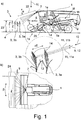
- eine vorschlagsgemäße Erntemaschine mit einer Sensoranordnung während des Aberntens eines Feldbestands a) in einer Seitenansicht und b) in einer Draufsicht,
- Fig. 2
- den Feldbestand gemäß
Fig. 1 in einer Ansicht entlang der Fahrtrichtung der Erntemaschine und - Fig. 3
- a) einen Sendepuls der Sensoranordnung gemäß
Fig. 1 und b ) der dem Sendepuls zugeordnete, resultierende Echopuls.
- Fig. 1
- a proposed harvesting machine with a sensor arrangement during the harvesting of a field crop a) in a side view and b) in a plan view,
- Fig. 2
- the field inventory according to
Fig. 1 in a view along the direction of travel of the harvester and - Fig. 3
- a) a transmission pulse of the sensor arrangement according to
Fig. 1 and b ) of the transmit pulse associated, resulting echo pulse.
Die in
Während des Erntebetriebs befindet sich der Feldbestand 2 in Fahrtrichtung 5 der Erntemaschine 1 gesehen vor der Erntemaschine 1. Von der Erntemaschine 1 aus gesehen existieren die vordersten Pflanzen 3a und die bestandsinneren Pflanzen 3b.During the harvesting operation, the
Bei der dargestellten landwirtschaftlichen Erntemaschine 1 handelt es sich um eine selbstfahrende Erntemaschine für die Verarbeitung von aufgenommenem Erntegut in Korngut. Die dargestellte Erntemaschine 1 weist einen Fahrantrieb 1a, ein Eingangsaggregat 1b auf, das mit einem austauschbaren Erntevorsatz 1c ausgestattet ist. An den Erntevorsatz 1c schließt sich ein nicht austauschbarer Schrägförderer 1d an, der das über das Eingangsaggregat 1b aufgenommene Erntegut einem Dreschwerk 1e zuführt. Dem Dreschwerk 1e nachgelagert sind eine Abscheidevorrichtung 1f, eine Reinigungsvorrichtung 1g sowie eine Verteileinrichtung 1h zur Verteilung der Nichtkornbestandteile auf dem Feld.In the illustrated
Die Erntemaschine 1 weist eine Steuerungsanordnung 6 und eine Sensoranordnung 7 auf, wobei mittels der Sensoranordnung 7 periodisch Sendepulse 8 aus elektromagnetischen Sendestrahlen in mindestens einer Senderichtung 10 auf den Feldbestand 2 ausgesendet werden. Die Sendepulse 8 werden am Feldbestand 2 reflektiert und als Echopulse 11 von der Sensoranordnung 7 empfangen.The harvesting
Eine Zusammenschau der
Es darf darauf hingewiesen werden, dass es sich bei der Darstellung des Sendestrahls 9 sowie der Teilstrahlen 12, 13 in der Zeichnung um einen idealisierten Zustand handelt. In einer realen Umgebung ergeben sich meist eine Vielzahl von Teilstrahlen 12, 13 aus ein und demselben Sendestrahl 9, auf die das vorschlagsgemäße Grundprinzip jeweils analog anwendbar ist. Insoweit gelten alle Ausführungen zu den Teilstrahlen 12, 13 für alle anderen, eventuell auftretenden Teilstrahlen entsprechend.It may be pointed out that the representation of the transmission beam 9 and of the
Aus der zeitversetzten Reflexion der Teilstrahlen 12, 13 ergibt sich, dass sich der jeweils resultierende Echopuls 11 aus entsprechend zeitversetzten Teil-Echopulsen 11a, 11b zusammensetzt, wie der Darstellung gemäß
Eine entsprechende Darstellung des resultierenden Echopulses 11 findet sich in
Eine Zusammenschau der
Der Fahrantrieb 1a und/oder die Arbeitsaggregate 1b werden mittels der Steuerungsanordnung 6 basierend auf der ermittelten Bestandsdichte angesteuert. Ein besonderer Vorteil dieser Art der Ansteuerung der beteiligten Komponenten besteht darin, dass die Ansteuerung vorausschauend vorgenommen wird, derart, dass erste Maßnahmen zur Ansteuerung bereits getroffen werden können, noch bevor der Feldbestand 2 in die Erntemaschine 1 eingezogen wird.The
Neben dem Einsatz des vorschlagsgemäßen Wertes für die Bestandsdichte des Feldbestands 2 für eine vorausschauende Ansteuerung der Erntemaschine 1 ist es grundsätzlich auch denkbar, dass die ermittelte Bestandsdichte dazu dient, eine sensorgestützte Prozessüberwachung innerhalb der Erntemaschine 1 zu optimieren. In diesem Zusammenhang wird vorgeschlagen, dass die Erntemaschine 1 eine Durchsatzmessanordnung 25, insbesondere eine Schichthöhenmessanordnung zur Ermittlung eines Durchsatzes, aufweist und dass mittels der Steuerungsanordnung 6 der ermittelte Durchsatz mit der ermittelten Bestandsdichte abgeglichen wird. Dies bedeutet, dass von dem ermittelten Wert für die Bestandsdichte unter Berücksichtigung der Fahrgeschwindigkeit der Erntemaschine 1 ein Wert für den zu erwartenden Durchsatz berechnet wird und dass dieser berechnete Durchsatz mit dem von der Durchsatzmessanordnung 25 gemessenem Durchsatz abgeglichen wird. Der Begriff "Abgleich" bedeutet hier, dass eine Abweichung der sich gegenüberstehenden Durchsätze in einer entsprechenden Korrektur der Durchsatzmessanordnung 25 oder der Sensoranordnung 7 resultiert. Eine solche Korrektur kann beispielsweise durch einen Korrekturfaktor umgesetzt sein, mit dem der jeweils ermittelte Durchsatz multipliziert wird, um zu dem korrigierten Durchsatz zu gelangen.In addition to the use of the proposed value for the stock density of
Die Sensoranordnung 6 weist vorzugsweise einen Laserscanner auf, der an der Erntemaschine 1 angeordnet ist und der in einem Neigungswinkel α gegenüber der Horizontalen und in einem Scanwinkel β gegenüber der Fahrtrichtung 5 um die Vertikale die Sendestrahlen 9 auf den Feldbestand 2 richtet.The sensor arrangement 6 preferably has a laser scanner which is arranged on the harvesting
In besonders bevorzugter Ausgestaltung handelt es sich bei dem obigen zeitlichen Zusammenhang um den oben angesprochenen Zeitversatz ΔTv zwischen zwei Teil-Echopulsen 11a, 11b, hier und vorzugsweise zwischen dem ersten Teil-Echopuls 11a und dem letzten Teil-Echopuls 11b, die einem Sendepuls 9 zugeordnet sind.In a particularly preferred embodiment, the above temporal relationship is the above-mentioned time offset ΔTv between two
Weiter vorzugsweise ist es vorgesehen, dass der Zeitversatz ΔTv ermittelt wird, indem von der Pulsbreite 15 eine Normierungsbreite 18 subtrahiert wird, wobei die Normierungsbreite 18 vorzugsweise definiert ist durch die Pulsbreite 15a des resultierenden Echopulses 11a, die sich bei einer unterstellten Einfachreflexion des Sendestrahls 9 an einer Pflanze 3a des Feldbestands 2 ergeben würde. Bei dem dargestellten und insoweit bevorzugten Ausführungsbeispiel handelt es sich bei der Normierungsbreite 18 also um die Pulsbreite 15a des ersten Teil-Echopulses 11a. Dabei wird der Einfachheit halber unterstellt, dass die Pulsbreiten 15a, 15b der beiden Teil-Echopulse 11a, 11b zueinander identisch sind.Further preferably, it is provided that the time offset .DELTA.Tv is determined by a
Wie oben angesprochen, lässt sich der Wert für die Bestandsdichte grundsätzlich aus der Eindringtiefe ΔE ermitteln. Vorzugsweise ist es vorgesehen, dass der Wert für die Bestandsdichte ermittelt wird, indem der Kehrwert der Eindringtiefe ΔE des Sendestrahls 9 in den Feldbestand 2 gebildet wird und dass die Eindringtiefe ΔE aus dem Produkt des Zeitversatzes ΔTv mit der Ausbreitungsgeschwindigkeit und ggf. mit einem Normierungsfaktor ermittelt wird. Dieser Kehrwert ist dann noch mit einem Proportionalitätsfaktor zu multiplizieren, um je nach Definition der Bestandsdichte zu dem jeweils gewünschten Wert für die Bestandsdichte zu gelangen.As mentioned above, the value for the stock density can basically be determined from the penetration depth ΔE. Preferably, it is provided that the value for the crop density is determined by the reciprocal of the penetration depth .DELTA.E of the transmission beam 9 is formed in the
Bei Pflanzen 3 mit länglichen Ähren 14 ist der Messfleck vorzugsweise so ausgelegt, dass der Sendestrahl 9 an der betreffenden Ähre 14 vorbeistrahlen kann. Im Einzelnen ist es vorzugsweise so, dass die Pflanzen 3 längliche Ähren 14 mit einer mittleren Breitenerstreckung 19 ausbilden, wobei dem Sendestrahl 9 an den Ähren 14 der bezogen auf die jeweilige Senderichtung 10 vordersten Pflanzen 3a auf Grund seines Strahlquerschnitts ein Messfleck M zugeordnet ist, dessen Durchmesser 20 zumindest in einer Richtung größer, insbesondere um das mindestens zweifache größer, als die Breitenerstreckung 19 der Ähren 14 ist. Dieser Zusammenhang ist in
Für die Auslegung der Sensoranordnung 7 sind verschiedene vorteilhafte Varianten denkbar. Hier und vorzugsweise ist es so, dass die elektromagnetischen Strahlen optische Strahlen, insbesondere Laserstrahlen, sind, deren Senderichtung 10 mittels der Steuerungsanordnung 6 einstellbar ist. In besonders bevorzugter Ausgestaltung handelt es sich bei der Sensoranordnung 7 wie oben angesprochen um einen Laserscanner, der den Feldbestand 2 in horizontal ausgerichteten Zeilen abscannt.For the design of the
Vorzugsweise ist die Sensoranordnung 7 ganz allgemein als optischer Abstandssensor ausgestaltet, wobei mittels der Sensoranordnung 7 aus dem zeitlichen Abstand des Sendezeitpunkts Ts eines Sendepulses 8 zu dem Empfangszeitpunkt TE des zugeordneten Echopulses 11 ein Abstandswert 22 zwischen der Sensoranordnung 7 und der jeweils reflektierenden Pflanze 3a ermittelt wird. Wie weiter oben angesprochen, handelt es sich bei der Sensoranordnung 7 vorzugsweise um eine Time-of-Flight-Sensoranordnung.Preferably, the
Bis hierhin betrifft das vorschlagsgemäße Verfahren die Ermittlung eines Wertes für die Bestandsdichte des Feldbestands 2. Vorzugsweise ist es allerdings so, dass eine Vielzahl von Werten für die Bestandsdichte ermittelt werden, insbesondere dass der Wert für die Bestandsdichte für jeden Sendepuls 8 oder für jeden Sendepuls 8 einer Gruppe von Sendepulsen 8 ermittelt wird. Hier und vorzugsweise ist es dabei vorgesehen, dass die ermittelten Werte für die Bestandsdichte in einem statistischen Verfahren, insbesondere durch Mittelwertbildung, in einen Gesamtwert für die Bestandsdichte überführt werden.Up to this point, the proposed method relates to the determination of a value for the crop density of the
Eine besonders hohe Flexibilität für die Erntemaschine 1 im Hinblick auf das Abernten von Feldbeständen 2 unterschiedlichen Typs wird dadurch erreicht, dass der Wert für die Bestandsdichte nach einer Berechnungsvorschrift ermittelt wird und dass die Steuerungsanordnung 6 eingerichtet ist, in Abhängigkeit vom Typ des abzuerntenden Feldbestands 2 die der Ermittlung der Bestandsdichte zu Grunde liegende Berechnungsvorschrift aus einer Anzahl gespeicherter Berechnungsvorschriften auszuwählen oder zu modifizieren. Wie weiter oben angesprochen, ist damit eine Umstellung der Erntemaschine 1 auf unterschiedliche Typen von Feldbeständen 2 möglich, ohne dass eine mechanische Anpassung vorgenommen werden muss.A particularly high flexibility for the harvesting
Es wurde bereits darauf hingewiesen, dass es sich bei der Sensoranordnung 7 vorzugsweise um einen Laserscanner handelt. Dann ist es vorzugsweise so, dass die Senderichtung 10 der Sensoranordnung 7 mittels der Steuerungsanordnung 6 fortlaufend in horizontaler Richtung und/oder in vertikaler Richtung modifiziert wird. Bevorzugt ist dabei ein ebenfalls bereits angesprochenes, zeilenweises "Abtasten" des Feldbestands 2.It has already been pointed out that the
In besonders bevorzugter Ausgestaltung ist es vorgesehen, dass mittels der Steuerungsanordnung 6 aus den Abstandswerten und/oder den Werten für die Bestandsdichte eine Bestandshöhe 23 ermittelt wird. Im Falle des oben angesprochenen Laserscanners ist dabei ein zeilenweises Abtasten des Feldbestands 2 vorgesehen, wobei der Neigungswinkel α zunehmend flacher gewählt wird. Beim Erreichen der oberen Kammlinie des Feldbestands 2 ändern sich nicht nur die oben angesprochenen Abstandswerte, sondern auch die Werte für die Bestandsdichte sprunghaft, woraus sich die Lage der Kammlinie automatisiert erfassen lässt.In a particularly preferred embodiment, it is provided that a
Alternativ oder zusätzlich kann es vorgesehen sein, dass mittels der Steuerungsanordnung 6 aus den Abstandswerten und/oder den Werten für die Bestandsdichte die Lage einer seitlichen Bestandskante 24 ermittelt wird. Auch dies lässt sich durch die automatisierte Erfassung einer sprunghaften Änderung in den betreffenden Werten bewerkstelligen.Alternatively or additionally, it can be provided that the position of a
Alternativ oder zusätzlich ist es weiter vorgesehen, dass mittels der Steuerungsanordnung 6 aus den Abstandswerten und/oder den Werten für die Bestandsdichte die Lage eines Hindernisses ermittelt wird. Auch diese Ermittlung lässt sich auf die automatisierte Erfassung einer sprunghaften Änderung der betreffenden Werte zurückführen.Alternatively or additionally, it is further provided that the position of an obstacle is determined by means of the control arrangement 6 from the distance values and / or the values for the stock density. This determination can also be attributed to the automated detection of a sudden change in the values concerned.
Es darf abschließend noch darauf hingewiesen werden, dass mit der vorschlagsgemäßen Lösung neben der Bestandsdichte auch andere Umgebungsbedingungen ermittelt werden können, beispielsweise die Struktur des Feldbestands 2, die Kontur des Feldbestands 2, die Permeabilität der Pflanzen 3 o. dgl.Finally, it should be pointed out that with the proposed solution in addition to the stocking density other environmental conditions can be determined, for example, the structure of the
- 11
- Erntemaschineharvester
- 1a1a
- FahrantriebTravel drive
- 1b-h1b-h
- Arbeitsaggregateworking units
- 22
- Pflanzenplants
- 33
- Feldbestandcrop
- 3a3a
- vordere Pflanzenfront plants
- 3b3b
- hinteren Pflanzenrear plants
- 44
- Feldbodenfield soil
- 55
- Fahrtrichtungdirection of travel
- 66
- Steuerungsanordnungcontrol arrangement
- 77
- Sensoranordnungsensor arrangement
- 88th
- Sendepulsetransmission pulses
- 99
- Sendestrahltransmission beam
- 1010
- Senderichtungsend direction
- 1111
- Echopulsecho pulse
- 11a11a
- Teil-EchopulsPart-echo pulse
- 11b11b
- TeilechopulsPart echo pulse
- 12, 1312, 13
- Teilstrahlenpartial beams
- MM
- Messfleck vorneMeasuring spot in front
- M'M '
- Messfleck hintenMeasuring spot behind
- 1414
- Ähreear
- 14a14a
- vordere Ährefront ear
- 14b14b
- hintere Ährerear ear
- 1515
- Pulsbreitepulse width
- 15a15a
- Pulsbreitepulse width
- 15b15b
- Pulsbreitepulse width
- 1616
- Pulsflankepulse edge
- 1717
- letzte abfallende Pulsflankelast falling pulse edge
- 1818
- Normierungsbreitestandardization width
- 1919
- Breitenerstreckungwidth extension
- 2020
- Durchmesserdiameter
- 2121
- ausgenommener Bereichexempt area
- 2222
- Abstandswertdistance value
- 2323
- Bestandshöheinventory level
- 2424
- Bestandskantecrop edge
- 2525
- DurchsatzmessanordnungThroughput measurement arrangement
Claims (14)
dadurch gekennzeichnet,
dass für zumindest einen Teil der Sendepulse (8) unterschiedliche Teilstrahlen (12, 13) ein und desselben Sendestrahls (9) von in derjeweiligen Senderichtung (10) hintereinanderliegenden Pflanzen (3) des Feldbestands (2) zueinander zeitversetzt reflektiert werden, so dass sich der jeweils resultierende Echopuls (11) aus entsprechend zeitversetzten Teil-Echopulsen (11a, 11b) zusammensetzt, dass die Steuerungsanordnung (6) basierend auf einem zeitlichen Zusammenhang innerhalb des resultierenden Echopulses (11) einen Wert für die Bestandsdichte ermittelt und dass die Steuerungsanordnung (6) den Fahrantrieb (1a) und/oder die Arbeitsaggregate (11b-h) basierend auf der ermittelten Bestandsdichte ansteuert.Self-propelled harvesting machine for harvesting a field crop (2) from a plurality of plants (3), with a traction drive (1a), with several working units (1b-h), with a control arrangement (6) and with a sensor arrangement (7), wherein the Sensor arrangement (7) periodically emitting transmission pulses (8) from electromagnetic transmission beams (9) in at least one transmission direction (10) on the field inventory (2), wherein the transmission pulses (8) on field inventory (2) reflected and echo pulses (11) from the Sensor arrangement (7) are received,
characterized,
that different sub-beams (12, 13) of one and the same transmitting beam (9) are successively reflected in time relative to one another by plants (3) of the field crop (2) lying one behind the other in the respective transmitting direction (10), so that the each resulting echo pulse (11) composed of correspondingly time-offset partial echo pulses (11a, 11b) that the control arrangement (6) determines a value for the population density based on a temporal relationship within the resulting echo pulse (11) and that the control arrangement (6) controls the travel drive (1a) and / or the work units (11b-h) based on the determined stocking density.
Applications Claiming Priority (1)
| Application Number | Priority Date | Filing Date | Title |
|---|---|---|---|
| DE102018104207.8A DE102018104207A1 (en) | 2018-02-23 | 2018-02-23 | Self-propelled harvester |
Publications (2)
| Publication Number | Publication Date |
|---|---|
| EP3530099A1 true EP3530099A1 (en) | 2019-08-28 |
| EP3530099B1 EP3530099B1 (en) | 2021-09-15 |
Family
ID=64664651
Family Applications (1)
| Application Number | Title | Priority Date | Filing Date |
|---|---|---|---|
| EP18211549.3A Active EP3530099B1 (en) | 2018-02-23 | 2018-12-11 | Self-propelled harvester |
Country Status (3)
| Country | Link |
|---|---|
| US (1) | US11116132B2 (en) |
| EP (1) | EP3530099B1 (en) |
| DE (1) | DE102018104207A1 (en) |
Cited By (3)
| Publication number | Priority date | Publication date | Assignee | Title |
|---|---|---|---|---|
| US20210000010A1 (en) * | 2018-01-29 | 2021-01-07 | Deere & Company | Harvester crop mapping |
| EP4154698A1 (en) * | 2021-09-22 | 2023-03-29 | CLAAS E-Systems GmbH | Method for detecting ground level on an area to be processed by an agricultural working machine |
| US11812694B2 (en) | 2018-01-29 | 2023-11-14 | Deere & Company | Monitor system for a harvester |
Citations (6)
| Publication number | Priority date | Publication date | Assignee | Title |
|---|---|---|---|---|
| EP1271139A2 (en) | 2001-06-28 | 2003-01-02 | Deere & Company | Apparatus for measuring the quantity of standing plants in a field |
| DE102008043716A1 (en) | 2008-11-13 | 2010-05-20 | Deere & Company, Moline | Plants population density detecting device for use in harvester, has evaluation device determining population density of plants based on variation of duration of electromagnetic wave from transmitter to receiver in measurement direction |
| DE102011017621A1 (en) * | 2011-04-27 | 2012-10-31 | Deere & Company | Arrangement and method for detecting the amount of plants in a field |
| DE102011085380A1 (en) * | 2011-10-28 | 2013-05-02 | Deere & Company | Arrangement and method for the prospective investigation of plants to be picked up with a harvester |
| EP2591654A1 (en) * | 2011-11-09 | 2013-05-15 | Deere & Company | Assembly and method for automatic documentation of situations in outdoor work |
| DE102015118767A1 (en) * | 2015-11-03 | 2017-05-04 | Claas Selbstfahrende Erntemaschinen Gmbh | Environment detection device for agricultural machine |
Family Cites Families (4)
| Publication number | Priority date | Publication date | Assignee | Title |
|---|---|---|---|---|
| US20160366821A1 (en) * | 2012-12-14 | 2016-12-22 | Agco Corporation | Crop mat measurement through stereo imaging |
| DE102014205233A1 (en) * | 2014-03-20 | 2015-09-24 | Deere & Company | Harvester with predictive propulsion speed specification |
| US20190110394A1 (en) * | 2017-10-17 | 2019-04-18 | Kopper Kutter, LLC | Crop yield and obstruction detection system for a harvesting header |
| US11006577B2 (en) * | 2018-02-26 | 2021-05-18 | Cnh Industrial America Llc | System and method for adjusting operating parameters of an agricultural harvester based on estimated crop volume |
-
2018
- 2018-02-23 DE DE102018104207.8A patent/DE102018104207A1/en not_active Withdrawn
- 2018-12-11 EP EP18211549.3A patent/EP3530099B1/en active Active
-
2019
- 2019-02-22 US US16/282,900 patent/US11116132B2/en active Active
Patent Citations (6)
| Publication number | Priority date | Publication date | Assignee | Title |
|---|---|---|---|---|
| EP1271139A2 (en) | 2001-06-28 | 2003-01-02 | Deere & Company | Apparatus for measuring the quantity of standing plants in a field |
| DE102008043716A1 (en) | 2008-11-13 | 2010-05-20 | Deere & Company, Moline | Plants population density detecting device for use in harvester, has evaluation device determining population density of plants based on variation of duration of electromagnetic wave from transmitter to receiver in measurement direction |
| DE102011017621A1 (en) * | 2011-04-27 | 2012-10-31 | Deere & Company | Arrangement and method for detecting the amount of plants in a field |
| DE102011085380A1 (en) * | 2011-10-28 | 2013-05-02 | Deere & Company | Arrangement and method for the prospective investigation of plants to be picked up with a harvester |
| EP2591654A1 (en) * | 2011-11-09 | 2013-05-15 | Deere & Company | Assembly and method for automatic documentation of situations in outdoor work |
| DE102015118767A1 (en) * | 2015-11-03 | 2017-05-04 | Claas Selbstfahrende Erntemaschinen Gmbh | Environment detection device for agricultural machine |
Cited By (4)
| Publication number | Priority date | Publication date | Assignee | Title |
|---|---|---|---|---|
| US20210000010A1 (en) * | 2018-01-29 | 2021-01-07 | Deere & Company | Harvester crop mapping |
| US11744180B2 (en) * | 2018-01-29 | 2023-09-05 | Deere & Company | Harvester crop mapping |
| US11812694B2 (en) | 2018-01-29 | 2023-11-14 | Deere & Company | Monitor system for a harvester |
| EP4154698A1 (en) * | 2021-09-22 | 2023-03-29 | CLAAS E-Systems GmbH | Method for detecting ground level on an area to be processed by an agricultural working machine |
Also Published As
| Publication number | Publication date |
|---|---|
| US20190261569A1 (en) | 2019-08-29 |
| DE102018104207A1 (en) | 2019-08-29 |
| US11116132B2 (en) | 2021-09-14 |
| EP3530099B1 (en) | 2021-09-15 |
Similar Documents
| Publication | Publication Date | Title |
|---|---|---|
| EP3569049B1 (en) | Agricultural machine | |
| EP3165062B1 (en) | Agricultural vehicle with an environment detection device | |
| DE19743884C2 (en) | Device and method for the contactless detection of processing limits or corresponding guide variables | |
| DE19528663A1 (en) | Mobile agricultural or construction machine setting - using measured position for setting machine in dependence on calculated process parameter and/or surface characteristic data for each position | |
| EP3530099B1 (en) | Self-propelled harvester | |
| EP3300579A1 (en) | Self-propelled agricultural machine | |
| EP3530098B1 (en) | Method for determining the density of a crop | |
| EP2272312B1 (en) | Agricultural device | |
| EP0732045B1 (en) | Reflex-orientation device | |
| EP3300561B1 (en) | Self-propelled agricultural machine | |
| EP3766329A1 (en) | Agricultural harvesting machine | |
| EP2859787B1 (en) | Method for operating a picking device with deck plates with adjustable distance | |
| EP3738420B1 (en) | Method for operating a self-propelled agricultural working machine | |
| EP0992185B1 (en) | Ultra-sound locating automatic steering system | |
| DE2455836B2 (en) | Device for the automatic guidance of agricultural machinery | |
| EP3556209B1 (en) | Method and device for measuring distance on an agricultural distribution machine | |
| DE102018204301B4 (en) | Method for determining a stand height of field plants | |
| EP4154698A1 (en) | Method for detecting ground level on an area to be processed by an agricultural working machine | |
| DE102021124478A1 (en) | Method for distinguishing crop types from plants within a field stand | |
| EP4155775A1 (en) | Method for identifying objects and agricultural working machine | |
| EP3556210B1 (en) | Agricultural device with control device and method |
Legal Events
| Date | Code | Title | Description |
|---|---|---|---|
| PUAI | Public reference made under article 153(3) epc to a published international application that has entered the european phase |
Free format text: ORIGINAL CODE: 0009012 |
|
| STAA | Information on the status of an ep patent application or granted ep patent |
Free format text: STATUS: THE APPLICATION HAS BEEN PUBLISHED |
|
| AK | Designated contracting states |
Kind code of ref document: A1 Designated state(s): AL AT BE BG CH CY CZ DE DK EE ES FI FR GB GR HR HU IE IS IT LI LT LU LV MC MK MT NL NO PL PT RO RS SE SI SK SM TR |
|
| AX | Request for extension of the european patent |
Extension state: BA ME |
|
| STAA | Information on the status of an ep patent application or granted ep patent |
Free format text: STATUS: REQUEST FOR EXAMINATION WAS MADE |
|
| 17P | Request for examination filed |
Effective date: 20200228 |
|
| RBV | Designated contracting states (corrected) |
Designated state(s): AL AT BE BG CH CY CZ DE DK EE ES FI FR GB GR HR HU IE IS IT LI LT LU LV MC MK MT NL NO PL PT RO RS SE SI SK SM TR |
|
| STAA | Information on the status of an ep patent application or granted ep patent |
Free format text: STATUS: EXAMINATION IS IN PROGRESS |
|
| 17Q | First examination report despatched |
Effective date: 20200921 |
|
| STAA | Information on the status of an ep patent application or granted ep patent |
Free format text: STATUS: EXAMINATION IS IN PROGRESS |
|
| GRAP | Despatch of communication of intention to grant a patent |
Free format text: ORIGINAL CODE: EPIDOSNIGR1 |
|
| STAA | Information on the status of an ep patent application or granted ep patent |
Free format text: STATUS: GRANT OF PATENT IS INTENDED |
|
| RIC1 | Information provided on ipc code assigned before grant |
Ipc: G01S 7/48 20060101ALI20210325BHEP Ipc: G01S 17/88 20060101ALI20210325BHEP Ipc: G01S 17/02 20200101ALI20210325BHEP Ipc: G01S 17/42 20060101ALI20210325BHEP Ipc: A01D 41/127 20060101AFI20210325BHEP |
|
| INTG | Intention to grant announced |
Effective date: 20210421 |
|
| GRAS | Grant fee paid |
Free format text: ORIGINAL CODE: EPIDOSNIGR3 |
|
| GRAA | (expected) grant |
Free format text: ORIGINAL CODE: 0009210 |
|
| STAA | Information on the status of an ep patent application or granted ep patent |
Free format text: STATUS: THE PATENT HAS BEEN GRANTED |
|
| AK | Designated contracting states |
Kind code of ref document: B1 Designated state(s): AL AT BE BG CH CY CZ DE DK EE ES FI FR GB GR HR HU IE IS IT LI LT LU LV MC MK MT NL NO PL PT RO RS SE SI SK SM TR |
|
| REG | Reference to a national code |
Ref country code: CH Ref legal event code: EP |
|
| REG | Reference to a national code |
Ref country code: DE Ref legal event code: R096 Ref document number: 502018007068 Country of ref document: DE |
|
| REG | Reference to a national code |
Ref country code: IE Ref legal event code: FG4D Free format text: LANGUAGE OF EP DOCUMENT: GERMAN |
|
| REG | Reference to a national code |
Ref country code: AT Ref legal event code: REF Ref document number: 1429779 Country of ref document: AT Kind code of ref document: T Effective date: 20211015 |
|
| REG | Reference to a national code |
Ref country code: LT Ref legal event code: MG9D |
|
| REG | Reference to a national code |
Ref country code: NL Ref legal event code: MP Effective date: 20210915 |
|
| PG25 | Lapsed in a contracting state [announced via postgrant information from national office to epo] |
Ref country code: HR Free format text: LAPSE BECAUSE OF FAILURE TO SUBMIT A TRANSLATION OF THE DESCRIPTION OR TO PAY THE FEE WITHIN THE PRESCRIBED TIME-LIMIT Effective date: 20210915 Ref country code: FI Free format text: LAPSE BECAUSE OF FAILURE TO SUBMIT A TRANSLATION OF THE DESCRIPTION OR TO PAY THE FEE WITHIN THE PRESCRIBED TIME-LIMIT Effective date: 20210915 Ref country code: SE Free format text: LAPSE BECAUSE OF FAILURE TO SUBMIT A TRANSLATION OF THE DESCRIPTION OR TO PAY THE FEE WITHIN THE PRESCRIBED TIME-LIMIT Effective date: 20210915 Ref country code: RS Free format text: LAPSE BECAUSE OF FAILURE TO SUBMIT A TRANSLATION OF THE DESCRIPTION OR TO PAY THE FEE WITHIN THE PRESCRIBED TIME-LIMIT Effective date: 20210915 Ref country code: BG Free format text: LAPSE BECAUSE OF FAILURE TO SUBMIT A TRANSLATION OF THE DESCRIPTION OR TO PAY THE FEE WITHIN THE PRESCRIBED TIME-LIMIT Effective date: 20211215 Ref country code: LT Free format text: LAPSE BECAUSE OF FAILURE TO SUBMIT A TRANSLATION OF THE DESCRIPTION OR TO PAY THE FEE WITHIN THE PRESCRIBED TIME-LIMIT Effective date: 20210915 Ref country code: NO Free format text: LAPSE BECAUSE OF FAILURE TO SUBMIT A TRANSLATION OF THE DESCRIPTION OR TO PAY THE FEE WITHIN THE PRESCRIBED TIME-LIMIT Effective date: 20211215 |
|
| PG25 | Lapsed in a contracting state [announced via postgrant information from national office to epo] |
Ref country code: LV Free format text: LAPSE BECAUSE OF FAILURE TO SUBMIT A TRANSLATION OF THE DESCRIPTION OR TO PAY THE FEE WITHIN THE PRESCRIBED TIME-LIMIT Effective date: 20210915 Ref country code: GR Free format text: LAPSE BECAUSE OF FAILURE TO SUBMIT A TRANSLATION OF THE DESCRIPTION OR TO PAY THE FEE WITHIN THE PRESCRIBED TIME-LIMIT Effective date: 20211216 |
|
| PG25 | Lapsed in a contracting state [announced via postgrant information from national office to epo] |
Ref country code: IS Free format text: LAPSE BECAUSE OF FAILURE TO SUBMIT A TRANSLATION OF THE DESCRIPTION OR TO PAY THE FEE WITHIN THE PRESCRIBED TIME-LIMIT Effective date: 20220115 Ref country code: SM Free format text: LAPSE BECAUSE OF FAILURE TO SUBMIT A TRANSLATION OF THE DESCRIPTION OR TO PAY THE FEE WITHIN THE PRESCRIBED TIME-LIMIT Effective date: 20210915 Ref country code: SK Free format text: LAPSE BECAUSE OF FAILURE TO SUBMIT A TRANSLATION OF THE DESCRIPTION OR TO PAY THE FEE WITHIN THE PRESCRIBED TIME-LIMIT Effective date: 20210915 Ref country code: RO Free format text: LAPSE BECAUSE OF FAILURE TO SUBMIT A TRANSLATION OF THE DESCRIPTION OR TO PAY THE FEE WITHIN THE PRESCRIBED TIME-LIMIT Effective date: 20210915 Ref country code: PT Free format text: LAPSE BECAUSE OF FAILURE TO SUBMIT A TRANSLATION OF THE DESCRIPTION OR TO PAY THE FEE WITHIN THE PRESCRIBED TIME-LIMIT Effective date: 20220117 Ref country code: PL Free format text: LAPSE BECAUSE OF FAILURE TO SUBMIT A TRANSLATION OF THE DESCRIPTION OR TO PAY THE FEE WITHIN THE PRESCRIBED TIME-LIMIT Effective date: 20210915 Ref country code: NL Free format text: LAPSE BECAUSE OF FAILURE TO SUBMIT A TRANSLATION OF THE DESCRIPTION OR TO PAY THE FEE WITHIN THE PRESCRIBED TIME-LIMIT Effective date: 20210915 Ref country code: ES Free format text: LAPSE BECAUSE OF FAILURE TO SUBMIT A TRANSLATION OF THE DESCRIPTION OR TO PAY THE FEE WITHIN THE PRESCRIBED TIME-LIMIT Effective date: 20210915 Ref country code: EE Free format text: LAPSE BECAUSE OF FAILURE TO SUBMIT A TRANSLATION OF THE DESCRIPTION OR TO PAY THE FEE WITHIN THE PRESCRIBED TIME-LIMIT Effective date: 20210915 Ref country code: CZ Free format text: LAPSE BECAUSE OF FAILURE TO SUBMIT A TRANSLATION OF THE DESCRIPTION OR TO PAY THE FEE WITHIN THE PRESCRIBED TIME-LIMIT Effective date: 20210915 Ref country code: AL Free format text: LAPSE BECAUSE OF FAILURE TO SUBMIT A TRANSLATION OF THE DESCRIPTION OR TO PAY THE FEE WITHIN THE PRESCRIBED TIME-LIMIT Effective date: 20210915 |
|
| REG | Reference to a national code |
Ref country code: DE Ref legal event code: R097 Ref document number: 502018007068 Country of ref document: DE |
|
| PLBE | No opposition filed within time limit |
Free format text: ORIGINAL CODE: 0009261 |
|
| STAA | Information on the status of an ep patent application or granted ep patent |
Free format text: STATUS: NO OPPOSITION FILED WITHIN TIME LIMIT |
|
| PG25 | Lapsed in a contracting state [announced via postgrant information from national office to epo] |
Ref country code: MC Free format text: LAPSE BECAUSE OF FAILURE TO SUBMIT A TRANSLATION OF THE DESCRIPTION OR TO PAY THE FEE WITHIN THE PRESCRIBED TIME-LIMIT Effective date: 20210915 Ref country code: DK Free format text: LAPSE BECAUSE OF FAILURE TO SUBMIT A TRANSLATION OF THE DESCRIPTION OR TO PAY THE FEE WITHIN THE PRESCRIBED TIME-LIMIT Effective date: 20210915 |
|
| REG | Reference to a national code |
Ref country code: CH Ref legal event code: PL |
|
| 26N | No opposition filed |
Effective date: 20220616 |
|
| PG25 | Lapsed in a contracting state [announced via postgrant information from national office to epo] |
Ref country code: SI Free format text: LAPSE BECAUSE OF FAILURE TO SUBMIT A TRANSLATION OF THE DESCRIPTION OR TO PAY THE FEE WITHIN THE PRESCRIBED TIME-LIMIT Effective date: 20210915 |
|
| PG25 | Lapsed in a contracting state [announced via postgrant information from national office to epo] |
Ref country code: LU Free format text: LAPSE BECAUSE OF NON-PAYMENT OF DUE FEES Effective date: 20211211 Ref country code: IE Free format text: LAPSE BECAUSE OF NON-PAYMENT OF DUE FEES Effective date: 20211211 |
|
| PG25 | Lapsed in a contracting state [announced via postgrant information from national office to epo] |
Ref country code: LI Free format text: LAPSE BECAUSE OF NON-PAYMENT OF DUE FEES Effective date: 20211231 Ref country code: CH Free format text: LAPSE BECAUSE OF NON-PAYMENT OF DUE FEES Effective date: 20211231 |
|
| PG25 | Lapsed in a contracting state [announced via postgrant information from national office to epo] |
Ref country code: IT Free format text: LAPSE BECAUSE OF FAILURE TO SUBMIT A TRANSLATION OF THE DESCRIPTION OR TO PAY THE FEE WITHIN THE PRESCRIBED TIME-LIMIT Effective date: 20210915 |
|
| P01 | Opt-out of the competence of the unified patent court (upc) registered |
Effective date: 20230516 |
|
| PG25 | Lapsed in a contracting state [announced via postgrant information from national office to epo] |
Ref country code: CY Free format text: LAPSE BECAUSE OF FAILURE TO SUBMIT A TRANSLATION OF THE DESCRIPTION OR TO PAY THE FEE WITHIN THE PRESCRIBED TIME-LIMIT Effective date: 20210915 |
|
| PG25 | Lapsed in a contracting state [announced via postgrant information from national office to epo] |
Ref country code: HU Free format text: LAPSE BECAUSE OF FAILURE TO SUBMIT A TRANSLATION OF THE DESCRIPTION OR TO PAY THE FEE WITHIN THE PRESCRIBED TIME-LIMIT; INVALID AB INITIO Effective date: 20181211 |
|
| GBPC | Gb: european patent ceased through non-payment of renewal fee |
Effective date: 20221211 |
|
| PG25 | Lapsed in a contracting state [announced via postgrant information from national office to epo] |
Ref country code: GB Free format text: LAPSE BECAUSE OF NON-PAYMENT OF DUE FEES Effective date: 20221211 |
|
| PGFP | Annual fee paid to national office [announced via postgrant information from national office to epo] |
Ref country code: FR Payment date: 20231222 Year of fee payment: 6 Ref country code: DE Payment date: 20231214 Year of fee payment: 6 |
|
| PGFP | Annual fee paid to national office [announced via postgrant information from national office to epo] |
Ref country code: BE Payment date: 20231220 Year of fee payment: 6 |
|
| PG25 | Lapsed in a contracting state [announced via postgrant information from national office to epo] |
Ref country code: MK Free format text: LAPSE BECAUSE OF FAILURE TO SUBMIT A TRANSLATION OF THE DESCRIPTION OR TO PAY THE FEE WITHIN THE PRESCRIBED TIME-LIMIT Effective date: 20210915 |