EP3519702B1 - Hydraulic system with selector control valve - Google Patents
Hydraulic system with selector control valve Download PDFInfo
- Publication number
- EP3519702B1 EP3519702B1 EP17787286.8A EP17787286A EP3519702B1 EP 3519702 B1 EP3519702 B1 EP 3519702B1 EP 17787286 A EP17787286 A EP 17787286A EP 3519702 B1 EP3519702 B1 EP 3519702B1
- Authority
- EP
- European Patent Office
- Prior art keywords
- detent
- control valve
- selector
- valve
- main control
- Prior art date
- Legal status (The legal status is an assumption and is not a legal conclusion. Google has not performed a legal analysis and makes no representation as to the accuracy of the status listed.)
- Active
Links
- 239000012530 fluid Substances 0.000 claims description 112
- 230000007246 mechanism Effects 0.000 claims description 70
- 238000000034 method Methods 0.000 claims description 8
- 230000000712 assembly Effects 0.000 claims description 3
- 238000000429 assembly Methods 0.000 claims description 3
- 230000003213 activating effect Effects 0.000 description 5
- 238000010276 construction Methods 0.000 description 4
- 230000004913 activation Effects 0.000 description 3
- 230000008878 coupling Effects 0.000 description 3
- 238000010168 coupling process Methods 0.000 description 3
- 238000005859 coupling reaction Methods 0.000 description 3
- 230000004044 response Effects 0.000 description 3
- 230000008901 benefit Effects 0.000 description 2
- 230000001419 dependent effect Effects 0.000 description 2
- 238000010586 diagram Methods 0.000 description 2
- 230000000694 effects Effects 0.000 description 2
- 238000012423 maintenance Methods 0.000 description 2
- 230000008439 repair process Effects 0.000 description 2
- 230000002441 reversible effect Effects 0.000 description 2
- 230000009849 deactivation Effects 0.000 description 1
- 230000003028 elevating effect Effects 0.000 description 1
- 238000007373 indentation Methods 0.000 description 1
- 230000002401 inhibitory effect Effects 0.000 description 1
- 230000001681 protective effect Effects 0.000 description 1
- 230000000717 retained effect Effects 0.000 description 1
Images


Classifications
-
- F—MECHANICAL ENGINEERING; LIGHTING; HEATING; WEAPONS; BLASTING
- F15—FLUID-PRESSURE ACTUATORS; HYDRAULICS OR PNEUMATICS IN GENERAL
- F15B—SYSTEMS ACTING BY MEANS OF FLUIDS IN GENERAL; FLUID-PRESSURE ACTUATORS, e.g. SERVOMOTORS; DETAILS OF FLUID-PRESSURE SYSTEMS, NOT OTHERWISE PROVIDED FOR
- F15B13/00—Details of servomotor systems ; Valves for servomotor systems
- F15B13/02—Fluid distribution or supply devices characterised by their adaptation to the control of servomotors
- F15B13/04—Fluid distribution or supply devices characterised by their adaptation to the control of servomotors for use with a single servomotor
- F15B13/0401—Valve members; Fluid interconnections therefor
- F15B13/0402—Valve members; Fluid interconnections therefor for linearly sliding valves, e.g. spool valves
-
- F—MECHANICAL ENGINEERING; LIGHTING; HEATING; WEAPONS; BLASTING
- F16—ENGINEERING ELEMENTS AND UNITS; GENERAL MEASURES FOR PRODUCING AND MAINTAINING EFFECTIVE FUNCTIONING OF MACHINES OR INSTALLATIONS; THERMAL INSULATION IN GENERAL
- F16K—VALVES; TAPS; COCKS; ACTUATING-FLOATS; DEVICES FOR VENTING OR AERATING
- F16K11/00—Multiple-way valves, e.g. mixing valves; Pipe fittings incorporating such valves
- F16K11/02—Multiple-way valves, e.g. mixing valves; Pipe fittings incorporating such valves with all movable sealing faces moving as one unit
- F16K11/06—Multiple-way valves, e.g. mixing valves; Pipe fittings incorporating such valves with all movable sealing faces moving as one unit comprising only sliding valves, i.e. sliding closure elements
- F16K11/065—Multiple-way valves, e.g. mixing valves; Pipe fittings incorporating such valves with all movable sealing faces moving as one unit comprising only sliding valves, i.e. sliding closure elements with linearly sliding closure members
- F16K11/07—Multiple-way valves, e.g. mixing valves; Pipe fittings incorporating such valves with all movable sealing faces moving as one unit comprising only sliding valves, i.e. sliding closure elements with linearly sliding closure members with cylindrical slides
- F16K11/0704—Multiple-way valves, e.g. mixing valves; Pipe fittings incorporating such valves with all movable sealing faces moving as one unit comprising only sliding valves, i.e. sliding closure elements with linearly sliding closure members with cylindrical slides comprising locking elements
-
- B—PERFORMING OPERATIONS; TRANSPORTING
- B66—HOISTING; LIFTING; HAULING
- B66F—HOISTING, LIFTING, HAULING OR PUSHING, NOT OTHERWISE PROVIDED FOR, e.g. DEVICES WHICH APPLY A LIFTING OR PUSHING FORCE DIRECTLY TO THE SURFACE OF A LOAD
- B66F11/00—Lifting devices specially adapted for particular uses not otherwise provided for
- B66F11/04—Lifting devices specially adapted for particular uses not otherwise provided for for movable platforms or cabins, e.g. on vehicles, permitting workmen to place themselves in any desired position for carrying out required operations
- B66F11/044—Working platforms suspended from booms
-
- F—MECHANICAL ENGINEERING; LIGHTING; HEATING; WEAPONS; BLASTING
- F15—FLUID-PRESSURE ACTUATORS; HYDRAULICS OR PNEUMATICS IN GENERAL
- F15B—SYSTEMS ACTING BY MEANS OF FLUIDS IN GENERAL; FLUID-PRESSURE ACTUATORS, e.g. SERVOMOTORS; DETAILS OF FLUID-PRESSURE SYSTEMS, NOT OTHERWISE PROVIDED FOR
- F15B11/00—Servomotor systems without provision for follow-up action; Circuits therefor
- F15B11/16—Servomotor systems without provision for follow-up action; Circuits therefor with two or more servomotors
-
- F—MECHANICAL ENGINEERING; LIGHTING; HEATING; WEAPONS; BLASTING
- F15—FLUID-PRESSURE ACTUATORS; HYDRAULICS OR PNEUMATICS IN GENERAL
- F15B—SYSTEMS ACTING BY MEANS OF FLUIDS IN GENERAL; FLUID-PRESSURE ACTUATORS, e.g. SERVOMOTORS; DETAILS OF FLUID-PRESSURE SYSTEMS, NOT OTHERWISE PROVIDED FOR
- F15B20/00—Safety arrangements for fluid actuator systems; Applications of safety devices in fluid actuator systems; Emergency measures for fluid actuator systems
- F15B20/001—Double valve requiring the use of both hands simultaneously
-
- F—MECHANICAL ENGINEERING; LIGHTING; HEATING; WEAPONS; BLASTING
- F16—ENGINEERING ELEMENTS AND UNITS; GENERAL MEASURES FOR PRODUCING AND MAINTAINING EFFECTIVE FUNCTIONING OF MACHINES OR INSTALLATIONS; THERMAL INSULATION IN GENERAL
- F16K—VALVES; TAPS; COCKS; ACTUATING-FLOATS; DEVICES FOR VENTING OR AERATING
- F16K35/00—Means to prevent accidental or unauthorised actuation
- F16K35/04—Means to prevent accidental or unauthorised actuation yieldingly resisting the actuation
-
- F—MECHANICAL ENGINEERING; LIGHTING; HEATING; WEAPONS; BLASTING
- F15—FLUID-PRESSURE ACTUATORS; HYDRAULICS OR PNEUMATICS IN GENERAL
- F15B—SYSTEMS ACTING BY MEANS OF FLUIDS IN GENERAL; FLUID-PRESSURE ACTUATORS, e.g. SERVOMOTORS; DETAILS OF FLUID-PRESSURE SYSTEMS, NOT OTHERWISE PROVIDED FOR
- F15B13/00—Details of servomotor systems ; Valves for servomotor systems
- F15B13/14—Special measures for giving the operating person a "feeling" of the response of the actuated device
-
- F—MECHANICAL ENGINEERING; LIGHTING; HEATING; WEAPONS; BLASTING
- F15—FLUID-PRESSURE ACTUATORS; HYDRAULICS OR PNEUMATICS IN GENERAL
- F15B—SYSTEMS ACTING BY MEANS OF FLUIDS IN GENERAL; FLUID-PRESSURE ACTUATORS, e.g. SERVOMOTORS; DETAILS OF FLUID-PRESSURE SYSTEMS, NOT OTHERWISE PROVIDED FOR
- F15B13/00—Details of servomotor systems ; Valves for servomotor systems
- F15B13/02—Fluid distribution or supply devices characterised by their adaptation to the control of servomotors
- F15B13/04—Fluid distribution or supply devices characterised by their adaptation to the control of servomotors for use with a single servomotor
- F15B13/0401—Valve members; Fluid interconnections therefor
- F15B2013/0412—Valve members; Fluid interconnections therefor with three positions
-
- F—MECHANICAL ENGINEERING; LIGHTING; HEATING; WEAPONS; BLASTING
- F15—FLUID-PRESSURE ACTUATORS; HYDRAULICS OR PNEUMATICS IN GENERAL
- F15B—SYSTEMS ACTING BY MEANS OF FLUIDS IN GENERAL; FLUID-PRESSURE ACTUATORS, e.g. SERVOMOTORS; DETAILS OF FLUID-PRESSURE SYSTEMS, NOT OTHERWISE PROVIDED FOR
- F15B2211/00—Circuits for servomotor systems
- F15B2211/30—Directional control
- F15B2211/305—Directional control characterised by the type of valves
- F15B2211/3056—Assemblies of multiple valves
- F15B2211/3059—Assemblies of multiple valves having multiple valves for multiple output members
- F15B2211/30595—Assemblies of multiple valves having multiple valves for multiple output members with additional valves between the groups of valves for multiple output members
-
- F—MECHANICAL ENGINEERING; LIGHTING; HEATING; WEAPONS; BLASTING
- F15—FLUID-PRESSURE ACTUATORS; HYDRAULICS OR PNEUMATICS IN GENERAL
- F15B—SYSTEMS ACTING BY MEANS OF FLUIDS IN GENERAL; FLUID-PRESSURE ACTUATORS, e.g. SERVOMOTORS; DETAILS OF FLUID-PRESSURE SYSTEMS, NOT OTHERWISE PROVIDED FOR
- F15B2211/00—Circuits for servomotor systems
- F15B2211/30—Directional control
- F15B2211/32—Directional control characterised by the type of actuation
- F15B2211/321—Directional control characterised by the type of actuation mechanically
- F15B2211/324—Directional control characterised by the type of actuation mechanically manually, e.g. by using a lever or pedal
-
- F—MECHANICAL ENGINEERING; LIGHTING; HEATING; WEAPONS; BLASTING
- F15—FLUID-PRESSURE ACTUATORS; HYDRAULICS OR PNEUMATICS IN GENERAL
- F15B—SYSTEMS ACTING BY MEANS OF FLUIDS IN GENERAL; FLUID-PRESSURE ACTUATORS, e.g. SERVOMOTORS; DETAILS OF FLUID-PRESSURE SYSTEMS, NOT OTHERWISE PROVIDED FOR
- F15B2211/00—Circuits for servomotor systems
- F15B2211/80—Other types of control related to particular problems or conditions
- F15B2211/875—Control measures for coping with failures
- F15B2211/8752—Emergency operation mode, e.g. fail-safe operation mode
Definitions
- the present invention relates generally to a fluid flow control device, and more particularly to a selector control that directs fluid flow in response to an input command, particularly for use in operating a boom of a work vehicle.
- a boom-type apparatus such as an aerial work platform or mobile elevating work platform, is commonly used in industrial, construction, maintenance, repair, emergency, and other applications.
- a boom-type apparatus typically includes a lower boom mounted on a vehicle for swinging about one or more axes, and an upper boom that is extendable from the lower boom or which is pivotally connected to the lower boom for also swinging about one or more axes.
- the upper boom typically has a bucket or platform connected at its distal end for enabling a worker to perform one or more tasks at a normally inaccessible area, which is usually at an elevated position.
- Such a boom-type apparatus typically includes at least two working control valves for controlling one or more functions of the boom.
- a primary working control valve is usually disposed at the proximal end of the boom, such as in a cab of the vehicle, and may be used to control the boom from the ground.
- a secondary working control valve is usually disposed at the distal end of the boom, such as in the aerial bucket, and may be used to control the boom from the elevated position.
- a selector control valve is also typically disposed at the proximal end of the boom, and is used to operably couple either the primary working control valve or the secondary control valve for enabling operation of the boom.
- Such control valves may be hydraulic directional control valves, which are well-known in the art, and which may be operated by an external input command, such as a lever or joy stick that is operable by a human operator.
- selector control valves of the type described above typically prevent such accidental operation of the primary control valve by providing an emergency or failsafe state that must be actively selected by the operator to decouple the primary control.
- selector control valves typically include a detent mechanism having detent positions that correspond to activation of each of the primary control, the secondary control, and the failsafe state.
- requiring the user to actively select the failsafe detent position among the various detent positions may lead to mistakes or user error, which may allow the primary control to remain activated, and which may lead to undesirable results if the primary control functions are accidentally engaged.
- US Patent Publication No. US-2015/0013804A1 discloses a valve including a body with a spool bore, a supply passage, a tank passage, and a workport.
- a spool, in the spool bore has a first position providing a first path between the supply passage and the workport, a second position providing a second path between the tank passage and the workport, and a closed position.
- a latch assembly includes a cam that moves in response to pressure, a sphere engaged by the cam, and a notch.
- US Patent No. US-3128677A discloses a hydraulic system for a loader such as a hydraulically operated front end loader having a shovel mounted on the outer end of a boom for pivotal motion between carry and dump positions, and to an intermediate dig position at which the shovel is at a predetermined angle to the boom.
- a control valve has a detent device for a spool of a shovel tilt cylinder, to hold the spool in an operating position at which it causes tilting of the shovel away from its dump position and toward its carry position during the time the operator is occupied with manoeuvering the loader back to a digging location.
- a means to cancel automatically the effect of the biasing means, that is to disable the detent, can be activated as a consequence of the shovel reaching a position that bears a predetermined angular relation to the boom.
- the detent is for an operating element that is movable back and forth relative to a support.
- the detent device comprises two telescopic members mounted in telescoping relation, means for securing a first one of the telescopic memibers to the support and the second telescopic member to the operating element for movement therewith relative to the first telescopic member.
- Detent means is carried by one of the telescopic members for radial movement towards and from engagement in a recess in the other telescopic member to releasably hold the movable telescopic member in a detent defined position.
- Biasing means for the detent means yieldingly urges the same into engagement with the recess, and detent controlling positions at which it can be part carried by either the first or the second telescopic member and axially movable relative to the detent means toward and from detent controlling positions at which it can act on the biasing means to modify or cancel the effect thereof upon the detent means.
- Actuating means is operable to move the movable part towards and from its detent controlling position.
- a hydraulic system as claimed in claim 1 the hydraulic system comprising a selector control valve assembly.
- the present invention provides, inter alia, an improved selector control that automatically selects a failsafe state for deactivating a working control. More particularly, the selector control may be configured to activate the working control while continuous user input is applied to the selector control, and the selector control automatically selects the failsafe state when the user discontinues applying the input for maintaining activation of the working control.
- the invention has particular application for controlling a boom of a work vehicle.
- Such a configuration of the selector control to automatically select the failsafe state is advantageous in that the operator actively selects and continuously maintains input to the selector control before allowing operation of the machinery with the working control.
- a selector control may help to prevent the working control from being accidentally activated and engaged, which could interfere with a worker on a platform at the distal end of the boom.
- a selector control is also disclosed in this document, the selector control being manually operable by a user for activating or deactivating a primary working control or a secondary working control.
- the selector control may include a first state for activating the primary control and deactivating the secondary control, a second state for activating the secondary control and deactivating the primary control, and a failsafe state for deactivating both the primary control and the secondary control.
- the selector control may be configured to maintain the first state when continuous user input is applied to the selector control.
- the selector control is normally biased toward the failsafe state such that the selector control automatically selects the failsafe state when the user discontinues applying the user input for maintaining the first state.
- selector control is disclosed in this document, the selector control being operable by a user for selectively fluidly coupling a fluid flow source with a primary control or a secondary control, where the selector control includes: (i) a first state for selectively fluidly coupling the primary control with the fluid flow source and decoupling the secondary control from the fluid flow source, (ii) a second state for selectively fluidly coupling the secondary control with the fluid flow source and decoupling the primary control from the fluid flow source, and (iii) a failsafe state for decoupling both the primary control and the secondary control from the fluid flow source.
- the selector control may be manually operable by applying a user input to select the first state or the second state.
- the selector control may be configured to maintain the second state independent of continuous user input being applied to the selector control, and may be configured to maintain the first state when continuous user input is applied to the selector control.
- the selector control is normally biased toward the failsafe state such that the selector control automatically selects the failsafe state when the user discontinues applying the user input for maintaining the first state.
- the secondary control may be remote from the primary control.
- the secondary control may be disposed at a distal end of a boom, and the primary control may be disposed at a proximal end of the boom, the primary and secondary controls being coupleable to the fluid flow source to control one or more functions of the boom.
- the selector control may be disposed proximal the primary control, such that the user is capable of continuously applying an input to the selector control with one hand to maintain the first state for enabling operation of the primary control, and the user is capable of applying an input to the primary control with the other hand to control one or more functions of the boom.
- the selector control may be normally biased toward the failsafe state such that the selector control may automatically select the failsafe state when the user applies an input to exit the second state.
- the selector control may be a selector control valve assembly
- the primary control may be a primary working valve assembly
- the secondary control may be a secondary working valve assembly
- the selector control valve assembly may include a valve body having a fluid flow path for enabling fluid to flow to the primary working valve assembly, the secondary working valve assembly, or a fluid return line.
- the selector control valve assembly may also include a main control valve extending through at least a portion of the valve body and being manually movable in the fluid flow path relative to the valve body for directing fluid flow based on a position of the main control valve within the valve body.
- the first state may correspond to a first position of the main control valve for directing fluid flow to the primary working valve assembly.
- the second state may correspond to a second position of the main control valve for directing fluid flow to the secondary working valve assembly.
- the failsafe state may correspond to a failsafe position of the main control valve for directing fluid flow to the fluid return line.
- the selector control valve assembly may further include a selector mechanism operatively coupled to the main control valve, the selector mechanism being configured to maintain the main control valve in the second position independent of the user continuously applying user input to the main control valve, and being configured to maintain the first position when the user continuously applies user input to the main control valve.
- the selector mechanism may be configured to bias the main control valve toward the failsafe position such that the main control valve automatically moves to the failsafe position when the user discontinues applying the user input to maintain the first position.
- the selector mechanism may be configured to bias the main control valve toward the failsafe position such that the main control valve automatically moves to the failsafe position when the user applies an input to exit the second position.
- the selector mechanism may include a detent mechanism, the detent mechanism including a detent sleeve having at least one detent groove, the at least one detent groove being configured to receive a corresponding detent member.
- the at least one detent groove may include a first detent groove, and the detent mechanism may be configured to maintain the main control valve in the second position when the detent member is received in the first detent groove.
- the detent sleeve may include an abutment surface configured to engage the detent member when the main control valve is in the first position, the abutment surface being configured to enable the user to sense the main control valve being positioned in the first position.
- the abutment surface may be interposed between the at least one detent groove corresponding to the second position and a position along the detent sleeve corresponding to the failsafe position.
- the detent sleeve may be devoid of a detent groove interposed between the abutment surface and the position along the detent sleeve corresponding to the failsafe position for enabling the main control valve to move freely to the failsafe position.
- the detent sleeve may have a radially inner surface forming an internal bore, and the radially inner surface may define the at least one detent groove and the abutment surface within the internal bore.
- the detent mechanism may include a detent holder slidably movable in the internal bore.
- the detent holder may be operatively connected to an axial end of the main control valve for common movement therewith.
- the detent holder may include a detent biasing member and a cam, wherein the detent biasing member may be configured to urge the cam against the detent member for urging the detent member radially outwardly toward the sleeve inner surface.
- the detent member may include a pair of spherical balls, wherein the cam is a spherical ball or a cone-shaped poppet.
- the selector mechanism may further include a main biasing spring configured to bias the main control valve toward the failsafe position.
- the user input is applied through a lever operatively coupled to the main control valve.
- the main control valve may be a main valve spool slidably disposed in the valve body, the main valve spool having a plurality of spool lands configured to cooperate with corresponding valve body lands for selectively directing fluid flow through the valve body.
- the valve body may have one or more flow passages for directing fluid flow to the primary working valve assembly, and one or more work ports for directing fluid flow to the secondary working valve assembly.
- the main control valve may be a valve spool slidably disposed within a spool bore of the valve housing, and wherein the one or more flow passages and the one or more work ports are fluidly connected to the spool bore.
- the valve body may have a bridge passage fluidly connecting the spool bore on opposite sides of the one or more flow passages that fluidly connect to the primary working valve assembly.
- a selector control valve assembly is provided that is operable by a user for selectively directing pressurized fluid to a primary working valve assembly, a secondary working valve assembly, or a fluid return line
- the selector control valve assembly comprising: a valve body having a fluid flow path for enabling fluid to flow to the primary working valve assembly, the secondary working valve assembly, or the fluid return line; a main control valve extending through at least a portion of the valve body and being movable in the fluid flow path relative to the valve body for directing fluid flow based on a position of the main control valve within the valve body, the main control valve being manually movable by applying a user input to select a first position for directing fluid flow to the primary working valve assembly, or to select a second position for directing fluid flow to the secondary working valve assembly; and a selector mechanism operatively coupled to the main control valve, the selector mechanism being configured to maintain the main control valve in the second position independent of the user continuously applying user input to the main control valve, and being configured
- the selector mechanism may be configured to bias the main control valve toward the failsafe position such that the main control valve automatically moves to the failsafe position when the user applies an input to disengage from the second position.
- selector control valve assembly being for selectively directing pressurized fluid to at least one working valve assembly and including: a valve body having a fluid flow path for enabling fluid to flow to the at least one working valve assembly; a main control valve extending through at least a portion of the valve body and being movable in the fluid flow path relative to the valve body for directing fluid flow based on a position of the main control valve within the valve body, the main control valve being operable to select a working position for directing fluid flow to the at least one working valve assembly; and a selector mechanism operatively coupled to the main control valve, the selector mechanism including a detent sleeve having at least one detent groove that is configured to securably receive a detent member when the main control valve is in the working position; wherein the selector mechanism includes a biasing device configured to move the main control valve toward a failsafe position for decoupling the at least one working valve assembly from fluid flow when the detent member is not securably received in
- a hydraulic system comprising: a source of fluid pressure; a primary control; a secondary control; and a selector control as defined in any of the relevant preceding clauses.
- a vehicle is disclosed, the vehicle having a boom that is controllable by the primary control or the secondary control according to any of the relevant preceding clauses.
- a vehicle may be provided, the vehicle having a boom that is controllable by the primary working valve assembly or the secondary working valve assembly according to any of the relevant preceding clauses.
- the method is a method of operating a boom having a primary control at a proximal end of the boom and a secondary control at a distal end of the boom, the method including: (i) operating the primary control, including: (a) manually selecting a first state of a selector control by continuously applying a user input such that the selector control fluidly couples a fluid flow source with the primary control, the selector control being biased toward a failsafe state for decoupling both the primary control and the secondary control, whereby the selector control automatically selects the failsafe state when the user discontinues applying the user input for selecting the first state; and (b) while the user continuously applies the user input to select the first state, manually controlling the primary control to operate one or more functions of the boom; or (ii) operating the secondary control, including: (a) manually selecting a second state of the selector control by applying a user input such that the selector control fluidly couples a fluid flow source with the secondary control, the selector control being configured to
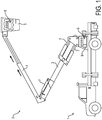
- the boom assembly 2 may include a lower boom 3 and an upper boom 4.
- the lower boom 3 may be mounted to the vehicle 1 about a pivot point for swinging about one or more axes, and the upper boom 4 may be extendable from the lower boom 3 and/or may be pivotally connected to the lower boom 3 for also swinging about one or more axes.
- the upper boom 4 may include a bucket 5 or platform connected at its distal end for enabling a worker to perform one or more tasks at a normally inaccessible area, such as at an elevated position.
- the boom assembly 2 may be operable by controlling one or more working controls, such as a primary control 6, which may direct fluid flow from a fluid flow source or fluid pressure source (shown in Fig. 3 ) to one or more actuators 7 or other fluid receiving devices so as to control one or more functions of the boom.
- a primary control 6 may direct fluid flow from a fluid flow source or fluid pressure source (shown in Fig. 3 ) to one or more actuators 7 or other fluid receiving devices so as to control one or more functions of the boom.
- the primary working control 6 may be disposed at the proximal end of the boom 2, such as in a bed or cab of the vehicle 1, and may be used to control the boom from the ground.
- a secondary working control 8 also may be provided to control one more functions of the boom 2.
- the secondary working control 8 may be substantially similar to the primary working control 6, but is usually disposed at the distal end of the boom 2, such as in the aerial bucket 5, so as to enable control of the boom from the elevated position.
- an exemplary selector control 9 is provided to operably couple either the primary working control 6 or the secondary working control 8 for enabling operation of the boom.
- the selector control 9 may be disposed at the proximal end of the boom and may be used simultaneously in conjunction with primary control 6, as will be discussed in further detail below.
- vehicle 1 and boom 2 are shown and described to facilitate an understanding of the invention and not by way of limitation.
- vehicle with boom are just one example of a work machine that may benefit from the present invention.
- Other types of work machines may include without limitation such work machines for use in industrial, construction, maintenance, repair, emergency, and other such applications, where the work machines may have multiple actuation functions, such as lifting arms, booms, buckets, as well as various other auxiliary functions.
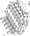
- valve section assembly 10 includes individual sections that are coupled together by bolts or other attachment in a known manner to provide an integral assembly.
- integral assembly means of a single piece construction or of a multi-piece construction assembled such that the multiple pieces function as a single piece without external fluid hoses or other external fluid pressure lines.
- the sections of the valve section assembly 10 may include an inlet section 12 adjacent a first end of the assembly of valve sections 10 and an outlet section 14 adjacent a second, opposite, end of the valve section assembly 10.
- the exemplary valve section assembly 10 may also include one or more working valve sections 16, 17, 18, 19 that are interposed between the inlet section 12 and the outlet section 14.
- the working valve sections 16, 17, 18, 19 may together form a primary working valve assembly 20, or primary control, which may be used to control one or more functions of a boom, for example.
- the primary working valve assembly 20 may correspond with the primary working control 6 shown in Fig. 1 .
- Each of the working sections 16, 17, 18, 19 may include a main flow control valve that is manually operable by applying a user input to a lever or joystick to control one or more functions of the boom, such as tilting, rotating, extending, lowering, or raising the boom.
- the valve section assembly 10 also includes an exemplary selector control valve assembly 22 interposed between the inlet section 12 and the primary working valve assembly 20.
- the selector control valve assembly 22 is configured to enable activation or deactivation of the primary control valve assembly 20 and/or a secondary control valve assembly 24 (or secondary control, shown schematically in Fig. 3 ). In this manner, the selector control valve assembly 22 may correspond with the selector control 9 shown in Fig. 1 .
- the selector control valve assembly 22 is an integral part of the valve section assembly 10 adjacent to the primary control 20, which may enable simultaneous operation of both the selector control valve assembly 22 and the primary control valve assembly 20.
- the selector control valve assembly 22 could be separate and apart from the primary working valve assembly 20 depending on the system requirements, as would be appreciated by those having skill in the art.
- a schematic hydraulic circuit diagram showing an exemplary configuration of a hydraulic system including the assembly of valve sections 10 is shown.
- the hydraulic system includes a fluid flow source 26 (or fluid pressure source), such as a pump, that provides flow of pressurized fluid (e.g., hydraulic fluid) to the inlet section 12.
- the outlet section 14 may receive fluid flow from any of the sections 14, 22, 16, 17, 18, 19, and the outlet section 14 may have an outlet passage that enables the fluid to exit the assembly 10 to a reservoir 28.
- each working valve assembly section 16, 17, 18, 19 of the primary control assembly 20 may have a valve body (shown schematically as an envelope border), a fluid inlet passage 30, one or more outlet passages or work ports 32 and 34, and a fluid flow path fluidly connecting the inlet passage 30 and/or the one or more work ports 32, 34.
- the one or more working valve sections 16, 17, 18, 19 may be configured substantially the same as one another (as shown in the illustrated embodiment), or the working sections may be different from one another, and any number of the same or different working sections may be included in the assembly of valve sections depending on the system requirements.
- each working valve section 16, 17, 18, 19 of the primary control valve assembly 20 may include a main control valve 36 configured to control fluid flow and pressure from the inlet passage 30 to the one or more work ports 32, 34.
- the work ports 32, 34 may be fluidly connected to one or more associated hydraulic fluid receiving devices of the machinery to be controlled.
- the hydraulic fluid receiving devices may include one or more hydraulic storage devices such as tanks or accumulators, hydraulic linear or rotary actuators, such as hydraulic cylinders, rotary motors, such as gerotor or gear motors, other hydraulic valves or subsystems, and/or any other devices that receive hydraulic fluid.
- the primary control valve assembly 20 is disposed at a proximal end of a boom, such as within a bed of a vehicle carrying the boom, and the work ports 32, 34 are fluidly connected to actuators or other fluid receiving devices for enabling operation of the boom from ground level.
- the secondary control valve assembly 24 may be constructed substantially the same as or similar to the primary control valve assembly 20. As shown in the schematic illustration, the secondary control valve assembly 24 may be remote from the primary control valve assembly 20. In exemplary embodiments the secondary control valve assembly 24 is disposed at a distal end of a boom, such as within a bucket supported by the boom, which enables operation of the boom from an elevated position. In this manner, the secondary control valve assembly 24 may correspond with the secondary working control 8 shown in Fig. 1 .
- the selector control valve assembly 22 may have a valve body 40 (shown schematically as an envelope border), a fluid inlet passage 42, one or more outlet passages 44, 46, 48, including work ports 50 and 52, and a fluid flow path fluidly connecting the inlet passage 42 and/or the one or more outlet passages 44, 46, 48, 50, 52.
- the outlet passage 44 of the selector control valve assembly 22 may be fluidly connected to the inlet 30 of the primary control valve assembly 20, and the outlet passage(s) 50 and/or 52 may be fluidly connected to the secondary control valve assembly 24.
- the outlet passage 48 may be fluidly connected to a fluid return line 53 that is connected to the reservoir 28.
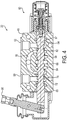
- the selector control valve assembly 22 may also include a main control valve 54 that is manually operable by a lever 56 for directing fluid flow based on a position of the main control valve 54 within the valve body 40.
- the main control valve 54 is a three-position, four-way valve that may enable three states of operation of the selector control 22.
- the main control valve 54 may be shifted to a first position 57 representing a first state in which the selector control 22 fluidly couples the primary control 20 with the fluid flow source 26 via outlet passage 44, and decouples the secondary control 24 from the fluid flow source 26.
- the main control valve 54 also may be shifted to a second position 58 representing a second state in which the selector control 22 fluidly couples the secondary control 24 with the fluid flow source 26 via work port 50 and/or 52, and in which the primary control 20 is decoupled from the fluid flow source 26.
- the main control valve 54 also may shift to a third position 59, or failsafe position, representing a failsafe state in which the selector control 22 directs fluid flow to the fluid return line 53 via outlet passage 48, such that both the primary control 20 and the secondary control 24 are decoupled from the fluid flow source 26, thereby preventing operation of the boom or other such machinery.
- the main control valve may be a three-position, three-way valve in which one of the workports is blocked.
- the selector control valve assembly 22 also includes a selector mechanism 60, or valve positioning assembly, that is operatively coupled to the main control valve 54.
- the selector mechanism 60 may be configured to maintain the above-described second state for activating the secondary control 24 independent of continuous user input being applied to the selector control 22.
- the operator on the ground may selectively activate the secondary control 24 by manually shifting the main control valve 54 to the second position 58 so as to allow a worker in the elevated bucket to control the boom with the secondary control 24 independent of input from the operator on the ground.
- the selector mechanism 60 also may be configured to maintain the above-described first state for activating the primary control 20 when continuous external input is applied to the selector control 22.
- the operator on the ground may activate the primary control 20 by manually shifting the main control valve 54 to the first position 57 so as to allow the operator on the ground to control the boom with the primary control 20 only while the operator is operatively holding the main control valve 54 and maintaining the selector control 22 in the first state.
- the selector mechanism 60 is further configured to normally bias the selector control 22 toward the failsafe state so as to automatically decouple the primary control 20 and secondary control 24 when the operator discontinues applying the user input to the selector control 22 for maintaining the first state.
- the selector mechanism 60 is configured to automatically shift the main control valve 54 to the failsafe position 59.
- Such a configuration of the selector control 22 to automatically select the failsafe state in this way improves the operation of the boom by ensuring that the operator actively selects and continuously maintains the selector control 22 in the first state before being able to control the boom with the primary control 20. This helps to prevent the primary control 20 from being accidentally activated and engaged, which otherwise could interfere with a worker in the bucket at the distal end of the boom.
- Fig. 3 the hydraulic system exemplified in Fig. 3 is provided for illustration purposes to show some of the possible options with exemplary valve assemblies or work sections. It is further understood that the illustrated system may not necessarily be used, as illustrated, for any particular job or on any particular hydraulic machine. For example, in other exemplary embodiments, less than four work sections are utilized. In other embodiments, more than four work sections are utilized. In one example, only one exemplary work section may be provided, while in another, every hydraulic function of a boom, for example, may have an associated exemplary work section.
- the valve body 40 is a unitary valve body having a fluid flow path for enabling fluid to flow to the primary working valve assembly 20, the secondary working valve assembly 24, or the fluid return line 53 (shown in Fig. 3 ).
- the main control valve 54 may be configured as a valve spool slidably disposed within a spool bore 62 of the valve housing 40.
- One or more flow passages 64, 65, 66, 67, 68 and/or the work ports 50, 52 may be fluidly connected to the spool bore 62.
- a bridge passage 70 also may be provided to fluidly connect to the spool bore 62 on opposite sides of the one or more passages 64, 66, 68.
- the main control valve 54 may be configured to extend through at least a portion of the valve body 40 and may be movable in the fluid flow path relative to the valve body for directing fluid flow based on a position of the main control valve within the valve body.
- the main control valve 54 may have a plurality of spool lands (e.g., 72) configured to cooperate with corresponding valve body lands (e.g., 74) for selectively directing fluid flow through the flow passages and/or work ports of the valve body.
- the main control valve 54 is operably connected to the lever 56 and may be manually movable by applying a user input to select a working position, such as the previously described first position or second position.
- the above-described selector mechanism 60 may be attached to the side of the valve body 40, for example toward an axial end of the main control valve 54.
- the selector mechanism 60 may include a bonnet assembly 76, or protective cap, that encloses a detent mechanism 78 and a main biasing spring 79.
- the detent mechanism 78 may include a detent sleeve 80 having a radially inner surface 81 that forms an internal bore, and a detent holder 82 configured to be slidably movable in the internal bore.
- the detent holder 82 may be operatively coupled to an axial end portion of the main control valve 54 for common movement therewith.
- the detent holder may have a radial shoulder 83 that engages the main biasing spring 79 for enabling the detent holder 82 and main valve 54 to shift in response to the spring force of the main spring 79.
- the main biasing spring 79 is retained by a spring collar 77, and the main spring is configured to urge the detent holder 82 inwardly toward the valve body 40.
- the detent holder 82 may also include one or more detent members 84, such as spherical detent balls.
- the detent members 84 may be disposed within channels 85 of the detent holder for enabling the detent members 84 to be carried by the detent holder 82 during sliding movement within the detent sleeve 80.
- the detent holder 82 may define an internal bore that contains a detent biasing spring 86, which may be contained by a spring collar 87.
- the biasing spring 86 may be configured to urge a cam 88, such as a camming ball or cone-shaped poppet, against the one or more detent members 84 for urging the detent members 84 radially outwardly toward the detent sleeve 80.
- the radially inner surface 81 of the detent sleeve may be configured to define at least one detent groove 89 that is configured to receive the one or more detent members 84.
- the detent groove 89 may be configured to secure the detent members 84 such that the spring force of the main spring 79 is insufficient to allow the detent members 84 to be extracted from the detent groove 89 without additional external input from the user.
- the term detent groove as used herein may include any indentation, ridge, recess, radial notch, or other such structure that is configured to retain the detent member.
- such a detent position in which the detent members 84 are securably received in the detent groove 89 may correspond with the main control valve 54 being shifted to the second position, in which the secondary control valve assembly 24 may be activated to allow a remote worker to control the functions of the boom, for example, independently of input from the operator on the ground.
- the radially inner surface 81 of the detent sleeve also may be configured to define an abutment surface 90 which may be interposed between the detent groove 89 and a position along the detent sleeve 80 that corresponds to the failsafe position.
- the abutment surface 90 may be configured to engage the one or more detent members 84 as the main control valve 54 is moved between the failsafe position and the first position so that the user may sense or feel this engagement. In exemplary embodiments, such a feel position in which the detent members 84 engage the abutment surface 90 corresponds with the main control valve 54 being shifted to the first position.
- abutment surface as used herein may include any ridge, bulge, protuberance, notch, or other such structure that is configured to provide an alert the user.
- a feel position may be provided by the abutment surface, it is understood that such a feel position may also be provided by a stop, such as a collar or a stroke limit of the main spool, or other such means that alert the user that the first state has been selected.
- the main biasing spring 79 biases the detent holder 82 away from the abutment surface 90 toward a position 91 along the detent sleeve 80 corresponding with the main valve 54 being shifted to the failsafe position.
- the radially inner surface 81 of the detent sleeve is essentially uniform and/or free of abutments or recesses between the sleeve position 91 and the abutment surface 90, which enables the detent holder 82 and main control valve 54 to freely move automatically toward the failsafe position when the operator discontinues applying user input to maintain the first position.
- Figs. 6A-6C an exemplary operation of the selector control valve assembly 22 will now be discussed.
- the selector control valve assembly 22 is shown in a failsafe state in which both the primary control 20 and the secondary control 24 are decoupled from the fluid flow source 26 (shown schematically in Fig. 3 ).
- the operator or user is not applying an external or user input to the lever 56, and the main spring 79 of the selector mechanism 60 biases the detent holder 82 fixed to the main valve 54 toward the failsafe position.
- fluid may flow from the fluid flow source 26 via the inlet section 12 (shown in Fig.
- the main control valve 54 being in its failsafe position blocks fluid flow to the outlet passages 64, 66, 68 and opens a flow path (shown with arrows) to the outlet passage 65 which is fluidly connected to fluid return line 53 connected to tank or reservoir 28 (shown in Fig. 3 ).
- the selector control valve assembly 22 is shown in a first state in which the primary control 20 is fluidly coupled to the fluid flow source 26 (shown in Fig. 3 ), which thereby enables operation of the boom, for example, with the primary control 20.
- the operator applies a user input (F) to the lever 56 to move the main control valve 54 from the failsafe position to the first position.
- the detent holder 82 fixed to the main valve 54 carries the detent members 84 along the detent sleeve 80 until the detent members 84 engage the abutment surface 90.
- the operator may feel the resistance of the detent members 84 engaging the abutment surface 90, which alerts the user that the main valve 54 is in the first position.
- fluid may flow from the fluid flow source 26 via the inlet section 12 (shown in Fig. 3 ) and through the passages 64, 66 and/or 68 downstream to one or more of the working sections 16, 17, 18, 19 of the primary control 20 (shown in Fig. 3 ).
- the main control valve 54 in this first position may block fluid flow to the outlet passage 65 and the work ports 50, 52.
- the main control valve 54 is maintained in the first position as long as the operator continues to apply input to the lever 56 to maintain the position of the main valve 54.
- the operator is capable of continuously applying such input with one hand to maintain the first state for enabling operation of the primary control 20, while using the other hand to apply input to the primary control to operate one or more functions of the boom, for example. If the operator were to release the lever 56 and discontinue such input to maintain the first position, then the main spring 79 of the selector mechanism 60 would automatically shift the main control valve 54 to the failsafe position, as illustrated in Fig. 6A .
- the selector control valve assembly 22 is shown in a second state in which the secondary control 24 is fluidly coupled to the fluid flow source 26 (shown in Fig. 3 ), which thereby enables operation of the boom, for example, with the secondary control 24.
- the operator may apply a user input to the lever 56 to move the main control valve 54 from the first position to the second position.
- the detent holder 82 fixed to the main valve 54 carries the detent members 84 over the abutment surface 90 until the detent members 84 are received in the detent groove 89 which alerts the user that the main valve 54 is in the second position.
- fluid may flow from the fluid flow source 26 via the inlet section 12 (shown in Fig. 3 ) to the inlet passage 93.
- the main control valve 54 being in the second position may block fluid flow to outlet passages 64, 66, 68 and 65, and may open a flow path (shown with arrows) to the work port 50 which is fluidly connected to the secondary control valve 24 (shown schematically in Fig. 3 ).
- the detent members 84 may be received in the detent groove 89, and the detent groove 89 may be configured to secure the detent members 84 such that the spring force of the main spring 79 is insufficient to allow the detent members 84 to be extracted from the detent groove 89 without additional input from the user.
- the user may release the lever 56 when the main valve 54 has been shifted to the second position so as to maintain the second operational state of the selector control 22 independent of continuous input from the operator. This may allow a worker in an elevated bucket to control the boom, for example, with the secondary control 24 independent of input from the operator on the ground.
- the selector mechanism 60 would automatically shift the main control valve 54 to the failsafe position (as illustrated in Fig. 6A ) when the operator discontinued such input after exiting the second position.
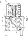
- Fig. 7 another exemplary embodiment of a selector mechanism 160 is shown.
- the selector mechanism 160 is substantially similar to the above-referenced selector mechanism 60, and consequently the same reference numerals but indexed by 100 are used to denote structures corresponding to similar structures.
- the foregoing description of the selector mechanism 60 is equally applicable to the selector mechanism 160 except as understood by the description below. It is also understood that aspects of the selector mechanisms 60, 160 may be substituted for one another or used in conjunction with one another where applicable.
- the selector mechanism 160 is essentially configured in reverse of the selector mechanism 60.
- the selector mechanism 160 may be attached to the side of a selector control valve body similarly to the selector mechanism 60, however, with the selector mechanism 160, the main biasing spring 179 is configured to bias the detent holder 182 outwardly away from the valve body.
- the configuration of the selector mechanism 160 would cause the main control valve to be shifted further to the right when compared to the main control valve 54 shown in Fig. 3
- the main control valve used with the selector mechanism 160 also may be configured essentially in reverse of the main control valve 54 to direct flow as desired, as would be understood by those with skill in the art.
- the selector mechanism 160 normally biases the detent holder 182 and detent mechanisms 184 toward position 191 along the detent sleeve 180, which corresponds with the failsafe position.
- the operator would then operatively shift the main control valve toward the left to engage the abutment surface 190 so as to alert the user that the main valve is in the first position. If the operator discontinued such input for maintaining the first position, the holder 182 fixed to the main control valve would shift back to the failsafe position.
- the operator could further operatively shift the main control valve toward the left such that the detent members 184 would be securably received in the detent groove 189 to maintain the main control valve in this position, which corresponds with the second operative position.
- the selector mechanism 160 could automatically shift the main control valve 54 to the failsafe position when the operator discontinued such input after exiting the second position.
- FIG. 8 another exemplary embodiment of a selector mechanism 260 is shown.
- the selector mechanism 260 is substantially similar to the above-referenced selector mechanism 60, and consequently the same reference numerals but indexed by 200 are used to denote structures corresponding to similar structures.
- the foregoing description of the selector mechanism 60 is equally applicable to the selector mechanism 260 except as understood by the description below. It is also understood that aspects of the selector mechanisms 60, 260 may be substituted for one another or used in conjunction with one another where applicable.
- the selector mechanism 260 is configured such that the main biasing spring 279 biases the detent holder 282 toward a center position 291 within the detent sleeve 270, which corresponds to the failsafe position.
- the operator would then operatively shift the main control valve toward the right to a stop position 296 in which the main spring 279 becomes fully compressed, or in which the spring collars 297 are engaged, so as to provide the operator with the feeling that the main control valve is in the first position. If the operator discontinued such input for maintaining the first position, which corresponds to position 296, then the holder 282 fixed to the main control valve would shift back toward the left to the failsafe position.
- the operator could further operatively shift the main control valve toward the left such that the detent members 284 would be securably received in the detent groove 289 to maintain the main control valve in this position, which corresponds with the second operative position.
- the selector mechanism 260 could automatically shift the main control valve to the failsafe position when the operator discontinued such input after exiting the second position.
Landscapes
- Engineering & Computer Science (AREA)
- General Engineering & Computer Science (AREA)
- Mechanical Engineering (AREA)
- Physics & Mathematics (AREA)
- Fluid Mechanics (AREA)
- Structural Engineering (AREA)
- Geology (AREA)
- Analytical Chemistry (AREA)
- Chemical & Material Sciences (AREA)
- Life Sciences & Earth Sciences (AREA)
- Mechanically-Actuated Valves (AREA)
- Preventing Unauthorised Actuation Of Valves (AREA)
- Operation Control Of Excavators (AREA)
Description
- The present invention relates generally to a fluid flow control device, and more particularly to a selector control that directs fluid flow in response to an input command, particularly for use in operating a boom of a work vehicle.
- A boom-type apparatus, such as an aerial work platform or mobile elevating work platform, is commonly used in industrial, construction, maintenance, repair, emergency, and other applications. Such a boom-type apparatus typically includes a lower boom mounted on a vehicle for swinging about one or more axes, and an upper boom that is extendable from the lower boom or which is pivotally connected to the lower boom for also swinging about one or more axes. The upper boom typically has a bucket or platform connected at its distal end for enabling a worker to perform one or more tasks at a normally inaccessible area, which is usually at an elevated position.
- Such a boom-type apparatus typically includes at least two working control valves for controlling one or more functions of the boom. A primary working control valve is usually disposed at the proximal end of the boom, such as in a cab of the vehicle, and may be used to control the boom from the ground. A secondary working control valve is usually disposed at the distal end of the boom, such as in the aerial bucket, and may be used to control the boom from the elevated position. In addition, a selector control valve is also typically disposed at the proximal end of the boom, and is used to operably couple either the primary working control valve or the secondary control valve for enabling operation of the boom. Such control valves may be hydraulic directional control valves, which are well-known in the art, and which may be operated by an external input command, such as a lever or joy stick that is operable by a human operator.
- The ability to control the boom from the ground enhances the utility of the boom-type apparatus, however, the worker supported by the aerial platform may be hindered if the primary control functions remain active and are accidentally engaged to allow the platform to rotate, tilt, lift, or the like. Known selector control valves of the type described above typically prevent such accidental operation of the primary control valve by providing an emergency or failsafe state that must be actively selected by the operator to decouple the primary control. For example, such known selector control valves typically include a detent mechanism having detent positions that correspond to activation of each of the primary control, the secondary control, and the failsafe state. However, requiring the user to actively select the failsafe detent position among the various detent positions may lead to mistakes or user error, which may allow the primary control to remain activated, and which may lead to undesirable results if the primary control functions are accidentally engaged.
- US Patent Publication No.
US-2015/0013804A1 discloses a valve including a body with a spool bore, a supply passage, a tank passage, and a workport. A spool, in the spool bore, has a first position providing a first path between the supply passage and the workport, a second position providing a second path between the tank passage and the workport, and a closed position. A latch assembly includes a cam that moves in response to pressure, a sphere engaged by the cam, and a notch. While the spool is in the second position, fluid flowing from the workport to the tank passage produces a first pressure, which causes the cam to hold the sphere in the notch, thereby inhibiting spool movement; and when the fluid flow from the workport to the tank passage terminates, a second pressure is produced causing the cam to allow the sphere to move out of the notch, thereby enabling the spool movement. - US Patent No.
US-3128677A discloses a hydraulic system for a loader such as a hydraulically operated front end loader having a shovel mounted on the outer end of a boom for pivotal motion between carry and dump positions, and to an intermediate dig position at which the shovel is at a predetermined angle to the boom. A control valve has a detent device for a spool of a shovel tilt cylinder, to hold the spool in an operating position at which it causes tilting of the shovel away from its dump position and toward its carry position during the time the operator is occupied with manoeuvering the loader back to a digging location. A means to cancel automatically the effect of the biasing means, that is to disable the detent, can be activated as a consequence of the shovel reaching a position that bears a predetermined angular relation to the boom. The detent is for an operating element that is movable back and forth relative to a support. The detent device comprises two telescopic members mounted in telescoping relation, means for securing a first one of the telescopic memibers to the support and the second telescopic member to the operating element for movement therewith relative to the first telescopic member. Detent means is carried by one of the telescopic members for radial movement towards and from engagement in a recess in the other telescopic member to releasably hold the movable telescopic member in a detent defined position. Biasing means for the detent means yieldingly urges the same into engagement with the recess, and detent controlling positions at which it can be part carried by either the first or the second telescopic member and axially movable relative to the detent means toward and from detent controlling positions at which it can act on the biasing means to modify or cancel the effect thereof upon the detent means. Actuating means is operable to move the movable part towards and from its detent controlling position. - According to an aspect of the present invention, there is provided a hydraulic system as claimed in claim 1, the hydraulic system comprising a selector control valve assembly.
- Optional further features of the hydraulic system are defined in the dependent claims.
- According to a second aspect of the present invention, there is provided a method of operating a boom as claimed in
claim 14. - Optional further features of the method are defined in a dependent claim.
- The present invention provides, inter alia, an improved selector control that automatically selects a failsafe state for deactivating a working control. More particularly, the selector control may be configured to activate the working control while continuous user input is applied to the selector control, and the selector control automatically selects the failsafe state when the user discontinues applying the input for maintaining activation of the working control. The invention has particular application for controlling a boom of a work vehicle.
- Such a configuration of the selector control to automatically select the failsafe state is advantageous in that the operator actively selects and continuously maintains input to the selector control before allowing operation of the machinery with the working control. For example, in the context of operating a boom, such a selector control may help to prevent the working control from being accidentally activated and engaged, which could interfere with a worker on a platform at the distal end of the boom.
- A selector control is also disclosed in this document, the selector control being manually operable by a user for activating or deactivating a primary working control or a secondary working control. The selector control may include a first state for activating the primary control and deactivating the secondary control, a second state for activating the secondary control and deactivating the primary control, and a failsafe state for deactivating both the primary control and the secondary control. The selector control may be configured to maintain the first state when continuous user input is applied to the selector control. The selector control is normally biased toward the failsafe state such that the selector control automatically selects the failsafe state when the user discontinues applying the user input for maintaining the first state.
- Another selector control is disclosed in this document, the selector control being operable by a user for selectively fluidly coupling a fluid flow source with a primary control or a secondary control, where the selector control includes: (i) a first state for selectively fluidly coupling the primary control with the fluid flow source and decoupling the secondary control from the fluid flow source, (ii) a second state for selectively fluidly coupling the secondary control with the fluid flow source and decoupling the primary control from the fluid flow source, and (iii) a failsafe state for decoupling both the primary control and the secondary control from the fluid flow source.
- The selector control may be manually operable by applying a user input to select the first state or the second state. The selector control may be configured to maintain the second state independent of continuous user input being applied to the selector control, and may be configured to maintain the first state when continuous user input is applied to the selector control. The selector control is normally biased toward the failsafe state such that the selector control automatically selects the failsafe state when the user discontinues applying the user input for maintaining the first state.
- For example, the secondary control may be remote from the primary control.
- The secondary control may be disposed at a distal end of a boom, and the primary control may be disposed at a proximal end of the boom, the primary and secondary controls being coupleable to the fluid flow source to control one or more functions of the boom.
- The selector control may be disposed proximal the primary control, such that the user is capable of continuously applying an input to the selector control with one hand to maintain the first state for enabling operation of the primary control, and the user is capable of applying an input to the primary control with the other hand to control one or more functions of the boom.
- The selector control may be normally biased toward the failsafe state such that the selector control may automatically select the failsafe state when the user applies an input to exit the second state.
- The selector control may be a selector control valve assembly, the primary control may be a primary working valve assembly, and the secondary control may be a secondary working valve assembly.
- The selector control valve assembly may include a valve body having a fluid flow path for enabling fluid to flow to the primary working valve assembly, the secondary working valve assembly, or a fluid return line. The selector control valve assembly may also include a main control valve extending through at least a portion of the valve body and being manually movable in the fluid flow path relative to the valve body for directing fluid flow based on a position of the main control valve within the valve body.
- The first state may correspond to a first position of the main control valve for directing fluid flow to the primary working valve assembly.
- The second state may correspond to a second position of the main control valve for directing fluid flow to the secondary working valve assembly.
- The failsafe state may correspond to a failsafe position of the main control valve for directing fluid flow to the fluid return line.
- The selector control valve assembly may further include a selector mechanism operatively coupled to the main control valve, the selector mechanism being configured to maintain the main control valve in the second position independent of the user continuously applying user input to the main control valve, and being configured to maintain the first position when the user continuously applies user input to the main control valve.
- The selector mechanism may be configured to bias the main control valve toward the failsafe position such that the main control valve automatically moves to the failsafe position when the user discontinues applying the user input to maintain the first position.
- The selector mechanism may be configured to bias the main control valve toward the failsafe position such that the main control valve automatically moves to the failsafe position when the user applies an input to exit the second position.
- The selector mechanism may include a detent mechanism, the detent mechanism including a detent sleeve having at least one detent groove, the at least one detent groove being configured to receive a corresponding detent member.
- The at least one detent groove may include a first detent groove, and the detent mechanism may be configured to maintain the main control valve in the second position when the detent member is received in the first detent groove.
- The detent sleeve may include an abutment surface configured to engage the detent member when the main control valve is in the first position, the abutment surface being configured to enable the user to sense the main control valve being positioned in the first position.
- The abutment surface may be interposed between the at least one detent groove corresponding to the second position and a position along the detent sleeve corresponding to the failsafe position.
- The detent sleeve may be devoid of a detent groove interposed between the abutment surface and the position along the detent sleeve corresponding to the failsafe position for enabling the main control valve to move freely to the failsafe position.
- The detent sleeve may have a radially inner surface forming an internal bore, and the radially inner surface may define the at least one detent groove and the abutment surface within the internal bore.
- The detent mechanism may include a detent holder slidably movable in the internal bore.
- The detent holder may be operatively connected to an axial end of the main control valve for common movement therewith.
- The detent holder may include a detent biasing member and a cam, wherein the detent biasing member may be configured to urge the cam against the detent member for urging the detent member radially outwardly toward the sleeve inner surface. The detent member may include a pair of spherical balls, wherein the cam is a spherical ball or a cone-shaped poppet.
- The selector mechanism may further include a main biasing spring configured to bias the main control valve toward the failsafe position.
- The user input is applied through a lever operatively coupled to the main control valve.
- The main control valve may be a main valve spool slidably disposed in the valve body, the main valve spool having a plurality of spool lands configured to cooperate with corresponding valve body lands for selectively directing fluid flow through the valve body.
- The valve body may have one or more flow passages for directing fluid flow to the primary working valve assembly, and one or more work ports for directing fluid flow to the secondary working valve assembly. The main control valve may be a valve spool slidably disposed within a spool bore of the valve housing, and wherein the one or more flow passages and the one or more work ports are fluidly connected to the spool bore. The valve body may have a bridge passage fluidly connecting the spool bore on opposite sides of the one or more flow passages that fluidly connect to the primary working valve assembly.
- In the hydraulic system according to the invention, a selector control valve assembly is provided that is operable by a user for selectively directing pressurized fluid to a primary working valve assembly, a secondary working valve assembly, or a fluid return line, the selector control valve assembly comprising: a valve body having a fluid flow path for enabling fluid to flow to the primary working valve assembly, the secondary working valve assembly, or the fluid return line; a main control valve extending through at least a portion of the valve body and being movable in the fluid flow path relative to the valve body for directing fluid flow based on a position of the main control valve within the valve body, the main control valve being manually movable by applying a user input to select a first position for directing fluid flow to the primary working valve assembly, or to select a second position for directing fluid flow to the secondary working valve assembly; and a selector mechanism operatively coupled to the main control valve, the selector mechanism being configured to maintain the main control valve in the second position independent of the user continuously applying user input to the main control valve, and being configured to maintain the first position when the user continuously applies user input to the main control valve; wherein the selector mechanism is configured to bias the main control valve toward a failsafe position for directing fluid flow to the fluid return line and decoupling both the primary and secondary working valve assemblies, the selector mechanism being configured to automatically move the main control valve to the failsafe position when the user discontinues applying the user input to maintain the first position.
- In some embodiments, the selector mechanism may be configured to bias the main control valve toward the failsafe position such that the main control valve automatically moves to the failsafe position when the user applies an input to disengage from the second position.
- Another selector control valve assembly is disclosed in this document, the selector control valve assembly being for selectively directing pressurized fluid to at least one working valve assembly and including: a valve body having a fluid flow path for enabling fluid to flow to the at least one working valve assembly; a main control valve extending through at least a portion of the valve body and being movable in the fluid flow path relative to the valve body for directing fluid flow based on a position of the main control valve within the valve body, the main control valve being operable to select a working position for directing fluid flow to the at least one working valve assembly; and a selector mechanism operatively coupled to the main control valve, the selector mechanism including a detent sleeve having at least one detent groove that is configured to securably receive a detent member when the main control valve is in the working position; wherein the selector mechanism includes a biasing device configured to move the main control valve toward a failsafe position for decoupling the at least one working valve assembly from fluid flow when the detent member is not securably received in the detent groove.
- A hydraulic system is disclosed in this document, the hydraulic system comprising: a source of fluid pressure; a primary control; a secondary control; and a selector control as defined in any of the relevant preceding clauses.
- A vehicle is disclosed, the vehicle having a boom that is controllable by the primary control or the secondary control according to any of the relevant preceding clauses.
- A vehicle may be provided, the vehicle having a boom that is controllable by the primary working valve assembly or the secondary working valve assembly according to any of the relevant preceding clauses.
- In the method of operating a boom according to the invention, the method is a method of operating a boom having a primary control at a proximal end of the boom and a secondary control at a distal end of the boom, the method including: (i) operating the primary control, including: (a) manually selecting a first state of a selector control by continuously applying a user input such that the selector control fluidly couples a fluid flow source with the primary control, the selector control being biased toward a failsafe state for decoupling both the primary control and the secondary control, whereby the selector control automatically selects the failsafe state when the user discontinues applying the user input for selecting the first state; and (b) while the user continuously applies the user input to select the first state, manually controlling the primary control to operate one or more functions of the boom; or (ii) operating the secondary control, including: (a) manually selecting a second state of the selector control by applying a user input such that the selector control fluidly couples a fluid flow source with the secondary control, the selector control being configured to maintain the second state independent of the user input being continuously applied to the selector control; and (b) manually controlling the secondary control to operate one or more functions of the boom.
- The following description and the annexed drawings set forth certain illustrative embodiments of the invention. These embodiments are indicative, however, of but a few of the various ways in which the principles of the invention may be employed. Other objects, advantages and novel features according to aspects of the invention will become apparent from the following detailed description when considered in conjunction with the drawings.
- The annexed drawings, which are not necessarily to scale, show various aspects of the invention.
-
Fig. 1 is a perspective view of a vehicle having a boom mounted thereon, including an exemplary primary control, a secondary control, and a selector control in accordance with an embodiment of the invention. -
Fig. 2 is a perspective view of an exemplary assembly of valve sections including an exemplary selector control valve assembly according to an embodiment of the invention. -
Fig. 3 is an exemplary hydraulic circuit diagram including a schematic depiction of the valve section assembly inFig. 2 . -
Fig. 4 is a cross-sectional view of the selector control valve assembly inFig. 2 , including an exemplary selector mechanism. -
Fig. 5 is an enlarged cross-sectional view of the selector mechanism inFig. 4 . -
Figs. 6A-6C are cross-sectional views of the selector control valve assembly inFig. 4 at various states of operation. -
Fig. 7 is another exemplary selector mechanism according to an embodiment of the invention. -
Fig. 8 is another exemplary selector mechanism according to an embodiment of the invention. - The principles of the present invention have particular application to hydraulic control valves for controlling one or more functions of a boom, and thus will be described below chiefly in this context. It is also understood, however, that the principles of this invention may be applicable to other fluid circuits in other applications where it is desirable to selectively control fluid flow while providing a failsafe state that may be automatically selected to deactivate a working control, such as when an operator is no longer applying an input to maintain operation of the working control.
- Turning to
Fig. 1 , an exemplary vehicle 1 having aboom assembly 2, or boom, mounted thereon is shown. Theboom assembly 2 may include alower boom 3 and an upper boom 4. Thelower boom 3 may be mounted to the vehicle 1 about a pivot point for swinging about one or more axes, and the upper boom 4 may be extendable from thelower boom 3 and/or may be pivotally connected to thelower boom 3 for also swinging about one or more axes. The upper boom 4 may include abucket 5 or platform connected at its distal end for enabling a worker to perform one or more tasks at a normally inaccessible area, such as at an elevated position. - The
boom assembly 2 may be operable by controlling one or more working controls, such as aprimary control 6, which may direct fluid flow from a fluid flow source or fluid pressure source (shown inFig. 3 ) to one or more actuators 7 or other fluid receiving devices so as to control one or more functions of the boom. As shown, theprimary working control 6 may be disposed at the proximal end of theboom 2, such as in a bed or cab of the vehicle 1, and may be used to control the boom from the ground. A secondary working control 8 also may be provided to control one more functions of theboom 2. The secondary working control 8 may be substantially similar to theprimary working control 6, but is usually disposed at the distal end of theboom 2, such as in theaerial bucket 5, so as to enable control of the boom from the elevated position. In addition, anexemplary selector control 9 is provided to operably couple either theprimary working control 6 or the secondary working control 8 for enabling operation of the boom. As shown, theselector control 9 may be disposed at the proximal end of the boom and may be used simultaneously in conjunction withprimary control 6, as will be discussed in further detail below. - It is understood that the vehicle 1 and
boom 2 are shown and described to facilitate an understanding of the invention and not by way of limitation. As will be appreciated, the vehicle with boom are just one example of a work machine that may benefit from the present invention. Other types of work machines (including work vehicles) may include without limitation such work machines for use in industrial, construction, maintenance, repair, emergency, and other such applications, where the work machines may have multiple actuation functions, such as lifting arms, booms, buckets, as well as various other auxiliary functions. - Turning to
Fig. 2 , a perspective view of an exemplary assembly ofvalve sections 10 according to one embodiment is shown. In the illustrated embodiment, thevalve section assembly 10 includes individual sections that are coupled together by bolts or other attachment in a known manner to provide an integral assembly. As used herein, the term integral assembly means of a single piece construction or of a multi-piece construction assembled such that the multiple pieces function as a single piece without external fluid hoses or other external fluid pressure lines. - Generally, the sections of the
valve section assembly 10 may include aninlet section 12 adjacent a first end of the assembly ofvalve sections 10 and anoutlet section 14 adjacent a second, opposite, end of thevalve section assembly 10. The exemplaryvalve section assembly 10 may also include one or more workingvalve sections inlet section 12 and theoutlet section 14. The workingvalve sections valve assembly 20, or primary control, which may be used to control one or more functions of a boom, for example. In this manner, the primary workingvalve assembly 20 may correspond with theprimary working control 6 shown inFig. 1 . Each of the workingsections - As shown, the
valve section assembly 10 also includes an exemplary selectorcontrol valve assembly 22 interposed between theinlet section 12 and the primary workingvalve assembly 20. The selectorcontrol valve assembly 22 is configured to enable activation or deactivation of the primarycontrol valve assembly 20 and/or a secondary control valve assembly 24 (or secondary control, shown schematically inFig. 3 ). In this manner, the selectorcontrol valve assembly 22 may correspond with theselector control 9 shown inFig. 1 . In exemplary embodiments the selectorcontrol valve assembly 22 is an integral part of thevalve section assembly 10 adjacent to theprimary control 20, which may enable simultaneous operation of both the selectorcontrol valve assembly 22 and the primarycontrol valve assembly 20. However, it is also understood that the selectorcontrol valve assembly 22 could be separate and apart from the primary workingvalve assembly 20 depending on the system requirements, as would be appreciated by those having skill in the art. - Turning to
Fig. 3 , a schematic hydraulic circuit diagram showing an exemplary configuration of a hydraulic system including the assembly ofvalve sections 10 is shown. The hydraulic system includes a fluid flow source 26 (or fluid pressure source), such as a pump, that provides flow of pressurized fluid (e.g., hydraulic fluid) to theinlet section 12. Theoutlet section 14 may receive fluid flow from any of thesections outlet section 14 may have an outlet passage that enables the fluid to exit theassembly 10 to areservoir 28. - Generally, each working
valve assembly section primary control assembly 20 may have a valve body (shown schematically as an envelope border), afluid inlet passage 30, one or more outlet passages orwork ports inlet passage 30 and/or the one ormore work ports valve sections - In a known manner, each working
valve section control valve assembly 20 may include amain control valve 36 configured to control fluid flow and pressure from theinlet passage 30 to the one ormore work ports work ports control valve assembly 20 is disposed at a proximal end of a boom, such as within a bed of a vehicle carrying the boom, and thework ports - The secondary
control valve assembly 24 may be constructed substantially the same as or similar to the primarycontrol valve assembly 20. As shown in the schematic illustration, the secondarycontrol valve assembly 24 may be remote from the primarycontrol valve assembly 20. In exemplary embodiments the secondarycontrol valve assembly 24 is disposed at a distal end of a boom, such as within a bucket supported by the boom, which enables operation of the boom from an elevated position. In this manner, the secondarycontrol valve assembly 24 may correspond with the secondary working control 8 shown inFig. 1 . - The selector
control valve assembly 22 may have a valve body 40 (shown schematically as an envelope border), afluid inlet passage 42, one ormore outlet passages work ports inlet passage 42 and/or the one ormore outlet passages control valve assembly 22 may be fluidly connected to theinlet 30 of the primarycontrol valve assembly 20, and the outlet passage(s) 50 and/or 52 may be fluidly connected to the secondarycontrol valve assembly 24. In addition, theoutlet passage 48 may be fluidly connected to afluid return line 53 that is connected to thereservoir 28. - The selector
control valve assembly 22 may also include amain control valve 54 that is manually operable by alever 56 for directing fluid flow based on a position of themain control valve 54 within thevalve body 40. As shown, themain control valve 54 is a three-position, four-way valve that may enable three states of operation of theselector control 22. For example, in the exemplary embodiment themain control valve 54 may be shifted to afirst position 57 representing a first state in which theselector control 22 fluidly couples theprimary control 20 with thefluid flow source 26 via outlet passage 44, and decouples thesecondary control 24 from thefluid flow source 26. Themain control valve 54 also may be shifted to asecond position 58 representing a second state in which theselector control 22 fluidly couples thesecondary control 24 with thefluid flow source 26 viawork port 50 and/or 52, and in which theprimary control 20 is decoupled from thefluid flow source 26. Themain control valve 54 also may shift to athird position 59, or failsafe position, representing a failsafe state in which theselector control 22 directs fluid flow to thefluid return line 53 viaoutlet passage 48, such that both theprimary control 20 and thesecondary control 24 are decoupled from thefluid flow source 26, thereby preventing operation of the boom or other such machinery. It is understood that although a three-position, four-way valve is shown, other embodiments may include more or fewer positions or paths depending on the application, as understood by those having skill in the art. For example, in other embodiments, the main control valve may be a three-position, three-way valve in which one of the workports is blocked. - The selector
control valve assembly 22 also includes aselector mechanism 60, or valve positioning assembly, that is operatively coupled to themain control valve 54. Theselector mechanism 60 may be configured to maintain the above-described second state for activating thesecondary control 24 independent of continuous user input being applied to theselector control 22. For example, where the secondarycontrol valve assembly 24 is disposed at the distal end of a boom, for example, the operator on the ground may selectively activate thesecondary control 24 by manually shifting themain control valve 54 to thesecond position 58 so as to allow a worker in the elevated bucket to control the boom with thesecondary control 24 independent of input from the operator on the ground. - The
selector mechanism 60 also may be configured to maintain the above-described first state for activating theprimary control 20 when continuous external input is applied to theselector control 22. For example, in the example of operating a boom, the operator on the ground may activate theprimary control 20 by manually shifting themain control valve 54 to thefirst position 57 so as to allow the operator on the ground to control the boom with theprimary control 20 only while the operator is operatively holding themain control valve 54 and maintaining theselector control 22 in the first state. - The
selector mechanism 60 is further configured to normally bias theselector control 22 toward the failsafe state so as to automatically decouple theprimary control 20 andsecondary control 24 when the operator discontinues applying the user input to theselector control 22 for maintaining the first state. For example, in the example of operating a boom, where the operator on the ground stops holding themain control valve 54 of theselector control 22 in thefirst positon 57, theselector mechanism 60 is configured to automatically shift themain control valve 54 to thefailsafe position 59. Such a configuration of theselector control 22 to automatically select the failsafe state in this way improves the operation of the boom by ensuring that the operator actively selects and continuously maintains theselector control 22 in the first state before being able to control the boom with theprimary control 20. This helps to prevent theprimary control 20 from being accidentally activated and engaged, which otherwise could interfere with a worker in the bucket at the distal end of the boom. - It is understood that the hydraulic system exemplified in
Fig. 3 is provided for illustration purposes to show some of the possible options with exemplary valve assemblies or work sections. It is further understood that the illustrated system may not necessarily be used, as illustrated, for any particular job or on any particular hydraulic machine. For example, in other exemplary embodiments, less than four work sections are utilized. In other embodiments, more than four work sections are utilized. In one example, only one exemplary work section may be provided, while in another, every hydraulic function of a boom, for example, may have an associated exemplary work section. - Turning to
Fig. 4 , a cross-sectional view of an exemplary embodiment of the selectorcontrol valve section 22 is shown. In the illustrated embodiment, thevalve body 40 is a unitary valve body having a fluid flow path for enabling fluid to flow to the primary workingvalve assembly 20, the secondary workingvalve assembly 24, or the fluid return line 53 (shown inFig. 3 ). As shown, themain control valve 54 may be configured as a valve spool slidably disposed within a spool bore 62 of thevalve housing 40. One ormore flow passages work ports bridge passage 70 also may be provided to fluidly connect to the spool bore 62 on opposite sides of the one ormore passages - The
main control valve 54 may be configured to extend through at least a portion of thevalve body 40 and may be movable in the fluid flow path relative to the valve body for directing fluid flow based on a position of the main control valve within the valve body. Themain control valve 54 may have a plurality of spool lands (e.g., 72) configured to cooperate with corresponding valve body lands (e.g., 74) for selectively directing fluid flow through the flow passages and/or work ports of the valve body. As shown, themain control valve 54 is operably connected to thelever 56 and may be manually movable by applying a user input to select a working position, such as the previously described first position or second position. - Referring to
Figs. 4 and5 , the above-describedselector mechanism 60 may be attached to the side of thevalve body 40, for example toward an axial end of themain control valve 54. Theselector mechanism 60 may include abonnet assembly 76, or protective cap, that encloses adetent mechanism 78 and amain biasing spring 79. - The
detent mechanism 78 may include adetent sleeve 80 having a radiallyinner surface 81 that forms an internal bore, and adetent holder 82 configured to be slidably movable in the internal bore. Thedetent holder 82 may be operatively coupled to an axial end portion of themain control valve 54 for common movement therewith. The detent holder may have aradial shoulder 83 that engages themain biasing spring 79 for enabling thedetent holder 82 andmain valve 54 to shift in response to the spring force of themain spring 79. In the exemplary embodiment, themain biasing spring 79 is retained by aspring collar 77, and the main spring is configured to urge thedetent holder 82 inwardly toward thevalve body 40. - The
detent holder 82 may also include one ormore detent members 84, such as spherical detent balls. Thedetent members 84 may be disposed withinchannels 85 of the detent holder for enabling thedetent members 84 to be carried by thedetent holder 82 during sliding movement within thedetent sleeve 80. Thedetent holder 82 may define an internal bore that contains adetent biasing spring 86, which may be contained by aspring collar 87. The biasingspring 86 may be configured to urge acam 88, such as a camming ball or cone-shaped poppet, against the one ormore detent members 84 for urging thedetent members 84 radially outwardly toward thedetent sleeve 80. - The radially
inner surface 81 of the detent sleeve may be configured to define at least onedetent groove 89 that is configured to receive the one ormore detent members 84. Thedetent groove 89 may be configured to secure thedetent members 84 such that the spring force of themain spring 79 is insufficient to allow thedetent members 84 to be extracted from thedetent groove 89 without additional external input from the user. In this manner, it is understood that the term detent groove as used herein may include any indentation, ridge, recess, radial notch, or other such structure that is configured to retain the detent member. In exemplary embodiments, such a detent position in which thedetent members 84 are securably received in thedetent groove 89 may correspond with themain control valve 54 being shifted to the second position, in which the secondarycontrol valve assembly 24 may be activated to allow a remote worker to control the functions of the boom, for example, independently of input from the operator on the ground. - The radially
inner surface 81 of the detent sleeve also may be configured to define anabutment surface 90 which may be interposed between thedetent groove 89 and a position along thedetent sleeve 80 that corresponds to the failsafe position. Theabutment surface 90 may be configured to engage the one ormore detent members 84 as themain control valve 54 is moved between the failsafe position and the first position so that the user may sense or feel this engagement. In exemplary embodiments, such a feel position in which thedetent members 84 engage theabutment surface 90 corresponds with themain control valve 54 being shifted to the first position. In this manner, the operator may feel when themain control valve 54 has been shifted to the first position so as to alert the operator that theprimary controls 20 are activated. It is understood that the term abutment surface as used herein may include any ridge, bulge, protuberance, notch, or other such structure that is configured to provide an alert the user. In addition, although such a feel position may be provided by the abutment surface, it is understood that such a feel position may also be provided by a stop, such as a collar or a stroke limit of the main spool, or other such means that alert the user that the first state has been selected. - As shown, the
main biasing spring 79 biases thedetent holder 82 away from theabutment surface 90 toward aposition 91 along thedetent sleeve 80 corresponding with themain valve 54 being shifted to the failsafe position. In exemplary embodiments, the radiallyinner surface 81 of the detent sleeve is essentially uniform and/or free of abutments or recesses between thesleeve position 91 and theabutment surface 90, which enables thedetent holder 82 andmain control valve 54 to freely move automatically toward the failsafe position when the operator discontinues applying user input to maintain the first position. - Turning to
Figs. 6A-6C , an exemplary operation of the selectorcontrol valve assembly 22 will now be discussed. Referring toFig. 6A , the selectorcontrol valve assembly 22 is shown in a failsafe state in which both theprimary control 20 and thesecondary control 24 are decoupled from the fluid flow source 26 (shown schematically inFig. 3 ). In the illustrated state, the operator or user is not applying an external or user input to thelever 56, and themain spring 79 of theselector mechanism 60 biases thedetent holder 82 fixed to themain valve 54 toward the failsafe position. In this failsafe state, fluid may flow from thefluid flow source 26 via the inlet section 12 (shown inFig. 3 ) to aninlet passage 93 fluidly coupled to thebridge passage 70 of theselector valve body 40. Themain control valve 54 being in its failsafe position blocks fluid flow to theoutlet passages outlet passage 65 which is fluidly connected tofluid return line 53 connected to tank or reservoir 28 (shown inFig. 3 ). - Referring to
Fig. 6B , the selectorcontrol valve assembly 22 is shown in a first state in which theprimary control 20 is fluidly coupled to the fluid flow source 26 (shown inFig. 3 ), which thereby enables operation of the boom, for example, with theprimary control 20. Going fromFig. 6A to Fig. 6B , the operator applies a user input (F) to thelever 56 to move themain control valve 54 from the failsafe position to the first position. As themain control valve 54 moves toward the first position, thedetent holder 82 fixed to themain valve 54 carries thedetent members 84 along thedetent sleeve 80 until thedetent members 84 engage theabutment surface 90. The operator may feel the resistance of thedetent members 84 engaging theabutment surface 90, which alerts the user that themain valve 54 is in the first position. - In this first position, fluid may flow from the
fluid flow source 26 via the inlet section 12 (shown inFig. 3 ) and through thepassages sections Fig. 3 ). Themain control valve 54 in this first position may block fluid flow to theoutlet passage 65 and thework ports main control valve 54 is maintained in the first position as long as the operator continues to apply input to thelever 56 to maintain the position of themain valve 54. In this manner, the operator is capable of continuously applying such input with one hand to maintain the first state for enabling operation of theprimary control 20, while using the other hand to apply input to the primary control to operate one or more functions of the boom, for example. If the operator were to release thelever 56 and discontinue such input to maintain the first position, then themain spring 79 of theselector mechanism 60 would automatically shift themain control valve 54 to the failsafe position, as illustrated inFig. 6A . - Referring to
Fig. 6C , the selectorcontrol valve assembly 22 is shown in a second state in which thesecondary control 24 is fluidly coupled to the fluid flow source 26 (shown inFig. 3 ), which thereby enables operation of the boom, for example, with thesecondary control 24. Going fromFig. 6B to Fig. 6C , the operator may apply a user input to thelever 56 to move themain control valve 54 from the first position to the second position. As themain control valve 54 moves toward the second position, thedetent holder 82 fixed to themain valve 54 carries thedetent members 84 over theabutment surface 90 until thedetent members 84 are received in thedetent groove 89 which alerts the user that themain valve 54 is in the second position. In this second position, fluid may flow from thefluid flow source 26 via the inlet section 12 (shown inFig. 3 ) to theinlet passage 93. Themain control valve 54 being in the second position may block fluid flow tooutlet passages work port 50 which is fluidly connected to the secondary control valve 24 (shown schematically inFig. 3 ). - As discussed above, when the
main control valve 54 has been shifted to the second position, thedetent members 84 may be received in thedetent groove 89, and thedetent groove 89 may be configured to secure thedetent members 84 such that the spring force of themain spring 79 is insufficient to allow thedetent members 84 to be extracted from thedetent groove 89 without additional input from the user. In this manner, the user may release thelever 56 when themain valve 54 has been shifted to the second position so as to maintain the second operational state of theselector control 22 independent of continuous input from the operator. This may allow a worker in an elevated bucket to control the boom, for example, with thesecondary control 24 independent of input from the operator on the ground. In addition, if the operator on the ground applied an input to exit the second position (e.g., applied sufficient force enabling thedetent members 84 to be extracted or disengaged from the detent groove 89), then theselector mechanism 60 would automatically shift themain control valve 54 to the failsafe position (as illustrated inFig. 6A ) when the operator discontinued such input after exiting the second position. - Turning to
Fig. 7 , another exemplary embodiment of aselector mechanism 160 is shown. Theselector mechanism 160 is substantially similar to the above-referencedselector mechanism 60, and consequently the same reference numerals but indexed by 100 are used to denote structures corresponding to similar structures. In addition, the foregoing description of theselector mechanism 60 is equally applicable to theselector mechanism 160 except as understood by the description below. It is also understood that aspects of theselector mechanisms - As shown in the exemplary embodiment, the
selector mechanism 160 is essentially configured in reverse of theselector mechanism 60. Theselector mechanism 160 may be attached to the side of a selector control valve body similarly to theselector mechanism 60, however, with theselector mechanism 160, themain biasing spring 179 is configured to bias thedetent holder 182 outwardly away from the valve body. As such, the configuration of theselector mechanism 160 would cause the main control valve to be shifted further to the right when compared to themain control valve 54 shown inFig. 3 , and the main control valve used with theselector mechanism 160 also may be configured essentially in reverse of themain control valve 54 to direct flow as desired, as would be understood by those with skill in the art. - In the illustrated embodiment, the
selector mechanism 160 normally biases thedetent holder 182 anddetent mechanisms 184 towardposition 191 along thedetent sleeve 180, which corresponds with the failsafe position. The operator would then operatively shift the main control valve toward the left to engage theabutment surface 190 so as to alert the user that the main valve is in the first position. If the operator discontinued such input for maintaining the first position, theholder 182 fixed to the main control valve would shift back to the failsafe position. The operator could further operatively shift the main control valve toward the left such that thedetent members 184 would be securably received in thedetent groove 189 to maintain the main control valve in this position, which corresponds with the second operative position. In addition, if the operator applied an input to exit the second position (e.g., applied sufficient force to extract or disengage the detent members from the detent groove), then theselector mechanism 160 could automatically shift themain control valve 54 to the failsafe position when the operator discontinued such input after exiting the second position. - Turning to
Fig. 8 , another exemplary embodiment of aselector mechanism 260 is shown. Theselector mechanism 260 is substantially similar to the above-referencedselector mechanism 60, and consequently the same reference numerals but indexed by 200 are used to denote structures corresponding to similar structures. In addition, the foregoing description of theselector mechanism 60 is equally applicable to theselector mechanism 260 except as understood by the description below. It is also understood that aspects of theselector mechanisms - As shown in the exemplary embodiment, the
selector mechanism 260 is configured such that themain biasing spring 279 biases thedetent holder 282 toward acenter position 291 within the detent sleeve 270, which corresponds to the failsafe position. The operator would then operatively shift the main control valve toward the right to astop position 296 in which themain spring 279 becomes fully compressed, or in which thespring collars 297 are engaged, so as to provide the operator with the feeling that the main control valve is in the first position. If the operator discontinued such input for maintaining the first position, which corresponds to position 296, then theholder 282 fixed to the main control valve would shift back toward the left to the failsafe position. The operator could further operatively shift the main control valve toward the left such that thedetent members 284 would be securably received in thedetent groove 289 to maintain the main control valve in this position, which corresponds with the second operative position. In addition, if the operator applied an input to exit the second position (e.g., applied sufficient force to extract or disengage the detent members from the detent groove), then theselector mechanism 260 could automatically shift the main control valve to the failsafe position when the operator discontinued such input after exiting the second position.
Claims (15)
- A hydraulic system comprising,
a source of fluid pressure (26);
a primary working valve assembly (20);
a secondary working valve assembly (24); and
a selector control valve assembly (22) that is operable by a user for selectively directing pressurized fluid to the primary working valve assembly, the secondary working valve assembly, or a fluid return line (53), the selector control valve assembly comprising:a valve body (40) having a fluid flow path for enabling fluid to flow to the primary working valve assembly, the secondary working valve assembly, or the fluid return line;a main control valve (54) extending through at least a portion of the valve body and being movable in the fluid flow path relative to the valve body for directing fluid flow based on a position of the main control valve within the valve body, the main control valve being manually movable by applying a user input to select a first position for directing fluid flow to the primary working valve assembly, or to select a second position for directing fluid flow to the secondary working valve assembly; anda selector mechanism (60, 160, 260) operatively coupled to the main control valve, the selector mechanism being configured to maintain the main control valve in the second position independent of the user continuously applying user input to the main control valve, and being configured to maintain the first position when the user continuously applies user input to the main control valve;wherein the selector mechanism is configured to bias the main control valve toward a failsafe position for directing fluid flow to the fluid return line and decoupling both the primary and secondary working valve assemblies, the selector mechanism being configured to automatically move the main control valve to the failsafe position when the user discontinues applying the user input to maintain the first position. - The hydraulic system according to claim 1, wherein the selector mechanism is configured to bias the main control valve toward the failsafe position such that the main control valve automatically moves to the failsafe position when the user applies an input to disengage from the second position.
- The hydraulic system according to claim 1, or any other preceding claim, wherein the selector mechanism includes a detent mechanism (78, 184), the detent mechanism including a detent sleeve (80, 180, 270) having at least one detent groove (89, 189, 289), the at least one detent groove being configured to receive a corresponding detent member (84, 184, 284).
- The hydraulic system according to claim 3, wherein the at least one detent groove includes a first detent groove, and wherein the detent mechanism is configured to maintain the main control valve in the second position when the detent member is received in the first detent groove.
- The hydraulic system according to claim 3 or 4, wherein the detent sleeve includes an abutment surface (90, 190) configured to engage the detent member when the main control valve is in the first position, the abutment surface being configured to enable the user to sense the main control valve being positioned in the first position; optionally wherein the abutment surface is interposed between the at least one detent groove corresponding to the second position and a position along the detent sleeve corresponding to the failsafe position; optionally wherein the detent sleeve does not have a detent groove interposed between the abutment surface and the position along the detent sleeve corresponding to the failsafe position for enabling the main control valve to move freely to the failsafe position.
- The hydraulic system according to claim 5, wherein the detent sleeve has a radially inner surface (81) forming an internal bore, and wherein the radially inner surface defines the at least one detent groove and the abutment surface within the internal bore; wherein the detent mechanism includes a detent holder (82, 182, 282) slidably movable in the internal bore.
- The hydraulic system according to claim 6, wherein the detent holder is operatively connected to an axial end of the main control valve for common movement therewith.
- The hydraulic system according to claim 6, claim, wherein the detent holder includes a detent biasing member (86) and a cam (88), wherein the detent biasing member is configured to urge the cam against the detent member for urging the detent member radially outwardly toward the sleeve inner surface; optionally wherein the detent member includes a pair of spherical balls, and wherein the cam is a spherical ball or a cone-shaped poppet.
- The hydraulic system according to any of the preceding claims, wherein the selector mechanism further includes a main biasing spring (79, 179, 279) configured to bias the main control valve toward the failsafe position.
- The hydraulic system according to any of claims 1-9, wherein the user input is applied through a lever (56) operatively coupled to the main control valve.
- The hydraulic system according to any of the preceding claims, wherein the main control valve is a main valve spool slidably disposed in the valve body, the main valve spool having a plurality of spool lands (72) configured to cooperate with corresponding valve body lands (74) for selectively directing fluid flow through the valve body.
- The hydraulic system according to any of the preceding claims, wherein the valve body has one or more flow passages (64, 65, 66, 67, 68) for directing fluid flow to the primary working valve assembly, and one or more work ports (50, 52) for directing fluid flow to the secondary working valve assembly; optionally wherein the main control valve is a valve spool slidably disposed within a spool bore (62) of the valve housing, and wherein the one or more flow passages and the one or more work ports are fluidly connected to the spool bore; optionally wherein the valve body has a bridge passage (70) fluidly connecting the spool bore on opposite sides of the one or more flow passages that fluidly connect to the primary working valve assembly.
- The hydraulic system according to any of the preceding claims, wherein the second working valve assembly is disposable at a distal end of a boom (2), and the first working valve assembly is disposable at a proximal end of a boom.
- A method of operating a boom (2) having a primary control (6, 20) at a proximal end of the boom and a secondary control (8, 24) at a distal end of the boom, comprising:(i) operating the primary control, including:(a) manually selecting a first state of a selector control (9, 24) by continuously applying a user input such that the selector control fluidly couples a fluid flow source (26) with the primary control, the selector control being biased toward a failsafe state for decoupling both the primary control and the secondary control, whereby the selector control automatically selects the failsafe state when the user discontinues applying the user input for selecting the first state; and(b) while the user continuously applies the user input to select the first state, manually controlling the primary control to operate one or more functions of the boom; or(ii) operating the secondary control, including:(a) manually selecting a second state of the selector control by applying a user input such that the selector control fluidly couples the fluid flow source with the secondary control, the selector control being configured to maintain the second state independent of the user input being continuously applied to the selector control; and(b) manually controlling the secondary control to operate one or more functions of the boom.
- The method according to claim 14, wherein, when operating the primary control, one hand of the user applies the user input to the selector control to select the first state of the selector control, and the other hand of the user applies a user input to the primary control to control the one or more functions of the boom.
Applications Claiming Priority (2)
| Application Number | Priority Date | Filing Date | Title |
|---|---|---|---|
| US201662400877P | 2016-09-28 | 2016-09-28 | |
| PCT/US2017/053686 WO2018064148A1 (en) | 2016-09-28 | 2017-09-27 | Selector control valve |
Publications (2)
| Publication Number | Publication Date |
|---|---|
| EP3519702A1 EP3519702A1 (en) | 2019-08-07 |
| EP3519702B1 true EP3519702B1 (en) | 2020-11-04 |
Family
ID=60143759
Family Applications (1)
| Application Number | Title | Priority Date | Filing Date |
|---|---|---|---|
| EP17787286.8A Active EP3519702B1 (en) | 2016-09-28 | 2017-09-27 | Hydraulic system with selector control valve |
Country Status (3)
| Country | Link |
|---|---|
| US (1) | US11543039B2 (en) |
| EP (1) | EP3519702B1 (en) |
| WO (1) | WO2018064148A1 (en) |
Families Citing this family (1)
| Publication number | Priority date | Publication date | Assignee | Title |
|---|---|---|---|---|
| US11919756B2 (en) * | 2020-02-04 | 2024-03-05 | Xtreme Manufacturing, Llc | Aerial work vehicle boom auxiliary control panel |
Family Cites Families (9)
| Publication number | Priority date | Publication date | Assignee | Title |
|---|---|---|---|---|
| US3128677A (en) * | 1962-04-30 | 1964-04-14 | Hydraulic Unit Specialities Co | Control instrumentality having detent mechanism |
| US3373843A (en) | 1966-04-04 | 1968-03-19 | Parker Hannifin Corp | Flow and pressure control valve |
| US3790129A (en) * | 1971-07-15 | 1974-02-05 | Cessna Aircraft Co | Valve detent mechanism |
| US3866880A (en) * | 1973-10-09 | 1975-02-18 | Caterpillar Tractor Co | Valve assembly having a pressure responsive detent mechanism |
| US4098371A (en) | 1976-12-20 | 1978-07-04 | Fmc Corporation | Mobile scaffold |
| US4185427A (en) | 1978-06-01 | 1980-01-29 | Reach-All Manufacturing & Engineering Co. | Double cylinder over-center aerial device |
| US4265144A (en) * | 1978-12-26 | 1981-05-05 | Allis-Chalmers Corporation | Detent release for power shift transmission selector valve |
| US20150013804A1 (en) | 2013-07-10 | 2015-01-15 | Husco International, Inc. | Flow responsive latch for holding a spool valve in an open position |
| US10029897B2 (en) | 2014-04-30 | 2018-07-24 | Parker-Hannifin Corporation | Control valve and system with primary and auxiliary function control |
-
2017
- 2017-09-27 WO PCT/US2017/053686 patent/WO2018064148A1/en unknown
- 2017-09-27 US US16/332,595 patent/US11543039B2/en active Active
- 2017-09-27 EP EP17787286.8A patent/EP3519702B1/en active Active
Non-Patent Citations (1)
| Title |
|---|
| None * |
Also Published As
| Publication number | Publication date |
|---|---|
| EP3519702A1 (en) | 2019-08-07 |
| WO2018064148A1 (en) | 2018-04-05 |
| US11543039B2 (en) | 2023-01-03 |
| US20210285467A1 (en) | 2021-09-16 |
Similar Documents
| Publication | Publication Date | Title |
|---|---|---|
| US7409828B2 (en) | Control device | |
| CA2433120C (en) | Hydraulic control arrangement for a mobile operating machine | |
| EP2683879B1 (en) | Implement coupling system for a power machine | |
| EP0668407B1 (en) | Hydraulic interlock system with override capatility for skid steer loader | |
| US9689139B2 (en) | Quick coupler | |
| US7448208B2 (en) | Hydraulic arrangement for a lifting arm pivotably mounted on a vehicle | |
| JP2004301214A (en) | Hydraulic driving device for work vehicle | |
| US6260357B1 (en) | Quick coupler control system | |
| JPH03189407A (en) | Automatic pressure release device for hydraulic motor | |
| EP2189666B1 (en) | A hydraulic device for controlling an actuator. | |
| EP3519702B1 (en) | Hydraulic system with selector control valve | |
| US3978998A (en) | Fast hoist control system | |
| US8621860B2 (en) | Control system for work vehicle | |
| JP2013517437A (en) | Proportional valve assembly | |
| JP2004301215A (en) | Hydraulic driving device for work vehicle | |
| US5794511A (en) | Apparatus and method for controlling multiple fluid cylinders | |
| JP2020063788A (en) | Descent preventive valve device, blade device and work machine | |
| CN100371841C (en) | Selectable detent relief valve | |
| US10947996B2 (en) | Systems and methods for selective enablement of hydraulic operation | |
| JP5885787B2 (en) | Hydraulic control device | |
| JP6502813B2 (en) | Fluid pressure control device | |
| US20160145834A1 (en) | Vent for load sense valves | |
| EP3821136B1 (en) | Hydraulic machine comprising a hydraulic circuit | |
| GB2433551A (en) | Fluid circuit for remote consumer unit | |
| JP3026736U (en) | Jib hoisting device for truck crane |
Legal Events
| Date | Code | Title | Description |
|---|---|---|---|
| STAA | Information on the status of an ep patent application or granted ep patent |
Free format text: STATUS: UNKNOWN |
|
| STAA | Information on the status of an ep patent application or granted ep patent |
Free format text: STATUS: THE INTERNATIONAL PUBLICATION HAS BEEN MADE |
|
| PUAI | Public reference made under article 153(3) epc to a published international application that has entered the european phase |
Free format text: ORIGINAL CODE: 0009012 |
|
| STAA | Information on the status of an ep patent application or granted ep patent |
Free format text: STATUS: REQUEST FOR EXAMINATION WAS MADE |
|
| 17P | Request for examination filed |
Effective date: 20190319 |
|
| AK | Designated contracting states |
Kind code of ref document: A1 Designated state(s): AL AT BE BG CH CY CZ DE DK EE ES FI FR GB GR HR HU IE IS IT LI LT LU LV MC MK MT NL NO PL PT RO RS SE SI SK SM TR |
|
| AX | Request for extension of the european patent |
Extension state: BA ME |
|
| DAV | Request for validation of the european patent (deleted) | ||
| DAX | Request for extension of the european patent (deleted) | ||
| GRAP | Despatch of communication of intention to grant a patent |
Free format text: ORIGINAL CODE: EPIDOSNIGR1 |
|
| STAA | Information on the status of an ep patent application or granted ep patent |
Free format text: STATUS: GRANT OF PATENT IS INTENDED |
|
| INTG | Intention to grant announced |
Effective date: 20200602 |
|
| GRAS | Grant fee paid |
Free format text: ORIGINAL CODE: EPIDOSNIGR3 |
|
| GRAA | (expected) grant |
Free format text: ORIGINAL CODE: 0009210 |
|
| STAA | Information on the status of an ep patent application or granted ep patent |
Free format text: STATUS: THE PATENT HAS BEEN GRANTED |
|
| AK | Designated contracting states |
Kind code of ref document: B1 Designated state(s): AL AT BE BG CH CY CZ DE DK EE ES FI FR GB GR HR HU IE IS IT LI LT LU LV MC MK MT NL NO PL PT RO RS SE SI SK SM TR |
|
| REG | Reference to a national code |
Ref country code: GB Ref legal event code: FG4D |
|
| REG | Reference to a national code |
Ref country code: CH Ref legal event code: EP |
|
| REG | Reference to a national code |
Ref country code: AT Ref legal event code: REF Ref document number: 1331188 Country of ref document: AT Kind code of ref document: T Effective date: 20201115 |
|
| REG | Reference to a national code |
Ref country code: IE Ref legal event code: FG4D |
|
| REG | Reference to a national code |
Ref country code: DE Ref legal event code: R096 Ref document number: 602017027008 Country of ref document: DE |
|
| REG | Reference to a national code |
Ref country code: NL Ref legal event code: MP Effective date: 20201104 |
|
| REG | Reference to a national code |
Ref country code: AT Ref legal event code: MK05 Ref document number: 1331188 Country of ref document: AT Kind code of ref document: T Effective date: 20201104 |
|
| PG25 | Lapsed in a contracting state [announced via postgrant information from national office to epo] |
Ref country code: NO Free format text: LAPSE BECAUSE OF FAILURE TO SUBMIT A TRANSLATION OF THE DESCRIPTION OR TO PAY THE FEE WITHIN THE PRESCRIBED TIME-LIMIT Effective date: 20210204 Ref country code: GR Free format text: LAPSE BECAUSE OF FAILURE TO SUBMIT A TRANSLATION OF THE DESCRIPTION OR TO PAY THE FEE WITHIN THE PRESCRIBED TIME-LIMIT Effective date: 20210205 Ref country code: FI Free format text: LAPSE BECAUSE OF FAILURE TO SUBMIT A TRANSLATION OF THE DESCRIPTION OR TO PAY THE FEE WITHIN THE PRESCRIBED TIME-LIMIT Effective date: 20201104 Ref country code: PT Free format text: LAPSE BECAUSE OF FAILURE TO SUBMIT A TRANSLATION OF THE DESCRIPTION OR TO PAY THE FEE WITHIN THE PRESCRIBED TIME-LIMIT Effective date: 20210304 Ref country code: RS Free format text: LAPSE BECAUSE OF FAILURE TO SUBMIT A TRANSLATION OF THE DESCRIPTION OR TO PAY THE FEE WITHIN THE PRESCRIBED TIME-LIMIT Effective date: 20201104 |
|
| PG25 | Lapsed in a contracting state [announced via postgrant information from national office to epo] |
Ref country code: BG Free format text: LAPSE BECAUSE OF FAILURE TO SUBMIT A TRANSLATION OF THE DESCRIPTION OR TO PAY THE FEE WITHIN THE PRESCRIBED TIME-LIMIT Effective date: 20210204 Ref country code: SE Free format text: LAPSE BECAUSE OF FAILURE TO SUBMIT A TRANSLATION OF THE DESCRIPTION OR TO PAY THE FEE WITHIN THE PRESCRIBED TIME-LIMIT Effective date: 20201104 Ref country code: PL Free format text: LAPSE BECAUSE OF FAILURE TO SUBMIT A TRANSLATION OF THE DESCRIPTION OR TO PAY THE FEE WITHIN THE PRESCRIBED TIME-LIMIT Effective date: 20201104 Ref country code: IS Free format text: LAPSE BECAUSE OF FAILURE TO SUBMIT A TRANSLATION OF THE DESCRIPTION OR TO PAY THE FEE WITHIN THE PRESCRIBED TIME-LIMIT Effective date: 20210304 Ref country code: LV Free format text: LAPSE BECAUSE OF FAILURE TO SUBMIT A TRANSLATION OF THE DESCRIPTION OR TO PAY THE FEE WITHIN THE PRESCRIBED TIME-LIMIT Effective date: 20201104 Ref country code: ES Free format text: LAPSE BECAUSE OF FAILURE TO SUBMIT A TRANSLATION OF THE DESCRIPTION OR TO PAY THE FEE WITHIN THE PRESCRIBED TIME-LIMIT Effective date: 20201104 Ref country code: AT Free format text: LAPSE BECAUSE OF FAILURE TO SUBMIT A TRANSLATION OF THE DESCRIPTION OR TO PAY THE FEE WITHIN THE PRESCRIBED TIME-LIMIT Effective date: 20201104 |
|
| REG | Reference to a national code |
Ref country code: LT Ref legal event code: MG9D |
|
| PG25 | Lapsed in a contracting state [announced via postgrant information from national office to epo] |
Ref country code: HR Free format text: LAPSE BECAUSE OF FAILURE TO SUBMIT A TRANSLATION OF THE DESCRIPTION OR TO PAY THE FEE WITHIN THE PRESCRIBED TIME-LIMIT Effective date: 20201104 |
|
| PG25 | Lapsed in a contracting state [announced via postgrant information from national office to epo] |
Ref country code: SM Free format text: LAPSE BECAUSE OF FAILURE TO SUBMIT A TRANSLATION OF THE DESCRIPTION OR TO PAY THE FEE WITHIN THE PRESCRIBED TIME-LIMIT Effective date: 20201104 Ref country code: LT Free format text: LAPSE BECAUSE OF FAILURE TO SUBMIT A TRANSLATION OF THE DESCRIPTION OR TO PAY THE FEE WITHIN THE PRESCRIBED TIME-LIMIT Effective date: 20201104 Ref country code: EE Free format text: LAPSE BECAUSE OF FAILURE TO SUBMIT A TRANSLATION OF THE DESCRIPTION OR TO PAY THE FEE WITHIN THE PRESCRIBED TIME-LIMIT Effective date: 20201104 Ref country code: CZ Free format text: LAPSE BECAUSE OF FAILURE TO SUBMIT A TRANSLATION OF THE DESCRIPTION OR TO PAY THE FEE WITHIN THE PRESCRIBED TIME-LIMIT Effective date: 20201104 Ref country code: RO Free format text: LAPSE BECAUSE OF FAILURE TO SUBMIT A TRANSLATION OF THE DESCRIPTION OR TO PAY THE FEE WITHIN THE PRESCRIBED TIME-LIMIT Effective date: 20201104 Ref country code: SK Free format text: LAPSE BECAUSE OF FAILURE TO SUBMIT A TRANSLATION OF THE DESCRIPTION OR TO PAY THE FEE WITHIN THE PRESCRIBED TIME-LIMIT Effective date: 20201104 |
|
| REG | Reference to a national code |
Ref country code: DE Ref legal event code: R097 Ref document number: 602017027008 Country of ref document: DE |
|
| PG25 | Lapsed in a contracting state [announced via postgrant information from national office to epo] |
Ref country code: DK Free format text: LAPSE BECAUSE OF FAILURE TO SUBMIT A TRANSLATION OF THE DESCRIPTION OR TO PAY THE FEE WITHIN THE PRESCRIBED TIME-LIMIT Effective date: 20201104 |
|
| PLBE | No opposition filed within time limit |
Free format text: ORIGINAL CODE: 0009261 |
|
| STAA | Information on the status of an ep patent application or granted ep patent |
Free format text: STATUS: NO OPPOSITION FILED WITHIN TIME LIMIT |
|
| 26N | No opposition filed |
Effective date: 20210805 |
|
| PG25 | Lapsed in a contracting state [announced via postgrant information from national office to epo] |
Ref country code: AL Free format text: LAPSE BECAUSE OF FAILURE TO SUBMIT A TRANSLATION OF THE DESCRIPTION OR TO PAY THE FEE WITHIN THE PRESCRIBED TIME-LIMIT Effective date: 20201104 Ref country code: NL Free format text: LAPSE BECAUSE OF FAILURE TO SUBMIT A TRANSLATION OF THE DESCRIPTION OR TO PAY THE FEE WITHIN THE PRESCRIBED TIME-LIMIT Effective date: 20201104 |
|
| PG25 | Lapsed in a contracting state [announced via postgrant information from national office to epo] |
Ref country code: SI Free format text: LAPSE BECAUSE OF FAILURE TO SUBMIT A TRANSLATION OF THE DESCRIPTION OR TO PAY THE FEE WITHIN THE PRESCRIBED TIME-LIMIT Effective date: 20201104 |
|
| REG | Reference to a national code |
Ref country code: CH Ref legal event code: PL |
|
| REG | Reference to a national code |
Ref country code: BE Ref legal event code: MM Effective date: 20210930 |
|
| PG25 | Lapsed in a contracting state [announced via postgrant information from national office to epo] |
Ref country code: IS Free format text: LAPSE BECAUSE OF FAILURE TO SUBMIT A TRANSLATION OF THE DESCRIPTION OR TO PAY THE FEE WITHIN THE PRESCRIBED TIME-LIMIT Effective date: 20210304 Ref country code: MC Free format text: LAPSE BECAUSE OF FAILURE TO SUBMIT A TRANSLATION OF THE DESCRIPTION OR TO PAY THE FEE WITHIN THE PRESCRIBED TIME-LIMIT Effective date: 20201104 |
|
| PG25 | Lapsed in a contracting state [announced via postgrant information from national office to epo] |
Ref country code: LU Free format text: LAPSE BECAUSE OF NON-PAYMENT OF DUE FEES Effective date: 20210927 Ref country code: IE Free format text: LAPSE BECAUSE OF NON-PAYMENT OF DUE FEES Effective date: 20210927 Ref country code: FR Free format text: LAPSE BECAUSE OF NON-PAYMENT OF DUE FEES Effective date: 20210930 Ref country code: BE Free format text: LAPSE BECAUSE OF NON-PAYMENT OF DUE FEES Effective date: 20210930 |
|
| PG25 | Lapsed in a contracting state [announced via postgrant information from national office to epo] |
Ref country code: LI Free format text: LAPSE BECAUSE OF NON-PAYMENT OF DUE FEES Effective date: 20210930 Ref country code: CH Free format text: LAPSE BECAUSE OF NON-PAYMENT OF DUE FEES Effective date: 20210930 |
|
| P01 | Opt-out of the competence of the unified patent court (upc) registered |
Effective date: 20230524 |
|
| PG25 | Lapsed in a contracting state [announced via postgrant information from national office to epo] |
Ref country code: CY Free format text: LAPSE BECAUSE OF FAILURE TO SUBMIT A TRANSLATION OF THE DESCRIPTION OR TO PAY THE FEE WITHIN THE PRESCRIBED TIME-LIMIT Effective date: 20201104 |
|
| PG25 | Lapsed in a contracting state [announced via postgrant information from national office to epo] |
Ref country code: HU Free format text: LAPSE BECAUSE OF FAILURE TO SUBMIT A TRANSLATION OF THE DESCRIPTION OR TO PAY THE FEE WITHIN THE PRESCRIBED TIME-LIMIT; INVALID AB INITIO Effective date: 20170927 |
|
| PGFP | Annual fee paid to national office [announced via postgrant information from national office to epo] |
Ref country code: IT Payment date: 20230921 Year of fee payment: 7 Ref country code: GB Payment date: 20230927 Year of fee payment: 7 |
|
| PGFP | Annual fee paid to national office [announced via postgrant information from national office to epo] |
Ref country code: DE Payment date: 20230927 Year of fee payment: 7 |
|
| PG25 | Lapsed in a contracting state [announced via postgrant information from national office to epo] |
Ref country code: MK Free format text: LAPSE BECAUSE OF FAILURE TO SUBMIT A TRANSLATION OF THE DESCRIPTION OR TO PAY THE FEE WITHIN THE PRESCRIBED TIME-LIMIT Effective date: 20201104 |