EP3494316B1 - Bearing - Google Patents
Bearing Download PDFInfo
- Publication number
- EP3494316B1 EP3494316B1 EP17837500.2A EP17837500A EP3494316B1 EP 3494316 B1 EP3494316 B1 EP 3494316B1 EP 17837500 A EP17837500 A EP 17837500A EP 3494316 B1 EP3494316 B1 EP 3494316B1
- Authority
- EP
- European Patent Office
- Prior art keywords
- bearing
- flange
- feature
- generally cylindrical
- cylindrical sidewall
- Prior art date
- Legal status (The legal status is an assumption and is not a legal conclusion. Google has not performed a legal analysis and makes no representation as to the accuracy of the status listed.)
- Active
Links
- 239000002783 friction material Substances 0.000 claims description 19
- 238000000034 method Methods 0.000 claims description 19
- 229910052796 boron Inorganic materials 0.000 claims description 17
- 239000000758 substrate Substances 0.000 claims description 9
- 230000000295 complement effect Effects 0.000 description 9
- 239000000463 material Substances 0.000 description 8
- 230000000694 effects Effects 0.000 description 4
- 239000000945 filler Substances 0.000 description 4
- 229920002313 fluoropolymer Polymers 0.000 description 4
- 239000004811 fluoropolymer Substances 0.000 description 4
- 229920002312 polyamide-imide Polymers 0.000 description 4
- OKTJSMMVPCPJKN-UHFFFAOYSA-N Carbon Chemical compound [C] OKTJSMMVPCPJKN-UHFFFAOYSA-N 0.000 description 3
- 239000004696 Poly ether ether ketone Substances 0.000 description 3
- 239000004734 Polyphenylene sulfide Substances 0.000 description 3
- -1 ether ketone Chemical class 0.000 description 3
- 229920002530 polyetherether ketone Polymers 0.000 description 3
- 229920001470 polyketone Polymers 0.000 description 3
- 229920000069 polyphenylene sulfide Polymers 0.000 description 3
- 229920012287 polyphenylene sulfone Polymers 0.000 description 3
- 229920001780 ECTFE Polymers 0.000 description 2
- 239000004812 Fluorinated ethylene propylene Substances 0.000 description 2
- 239000002033 PVDF binder Substances 0.000 description 2
- 229920001774 Perfluoroether Polymers 0.000 description 2
- 239000004962 Polyamide-imide Substances 0.000 description 2
- 239000004697 Polyetherimide Substances 0.000 description 2
- VYPSYNLAJGMNEJ-UHFFFAOYSA-N Silicium dioxide Chemical compound O=[Si]=O VYPSYNLAJGMNEJ-UHFFFAOYSA-N 0.000 description 2
- GWEVSGVZZGPLCZ-UHFFFAOYSA-N Titan oxide Chemical compound O=[Ti]=O GWEVSGVZZGPLCZ-UHFFFAOYSA-N 0.000 description 2
- MCMNRKCIXSYSNV-UHFFFAOYSA-N Zirconium dioxide Chemical compound O=[Zr]=O MCMNRKCIXSYSNV-UHFFFAOYSA-N 0.000 description 2
- 239000000853 adhesive Substances 0.000 description 2
- 230000001070 adhesive effect Effects 0.000 description 2
- 125000003118 aryl group Chemical group 0.000 description 2
- WUKWITHWXAAZEY-UHFFFAOYSA-L calcium difluoride Chemical compound [F-].[F-].[Ca+2] WUKWITHWXAAZEY-UHFFFAOYSA-L 0.000 description 2
- 229910001634 calcium fluoride Inorganic materials 0.000 description 2
- 229910002091 carbon monoxide Inorganic materials 0.000 description 2
- 229920000840 ethylene tetrafluoroethylene copolymer Polymers 0.000 description 2
- 239000010439 graphite Substances 0.000 description 2
- 229910002804 graphite Inorganic materials 0.000 description 2
- 238000003475 lamination Methods 0.000 description 2
- 229920009441 perflouroethylene propylene Polymers 0.000 description 2
- 229920002493 poly(chlorotrifluoroethylene) Polymers 0.000 description 2
- 229920001643 poly(ether ketone) Polymers 0.000 description 2
- 239000005023 polychlorotrifluoroethylene (PCTFE) polymer Substances 0.000 description 2
- 229920000728 polyester Polymers 0.000 description 2
- 229920001601 polyetherimide Polymers 0.000 description 2
- 229920000642 polymer Polymers 0.000 description 2
- 229920001343 polytetrafluoroethylene Polymers 0.000 description 2
- 239000004810 polytetrafluoroethylene Substances 0.000 description 2
- 229920002981 polyvinylidene fluoride Polymers 0.000 description 2
- BQCIDUSAKPWEOX-UHFFFAOYSA-N 1,1-Difluoroethene Chemical compound FC(F)=C BQCIDUSAKPWEOX-UHFFFAOYSA-N 0.000 description 1
- CHJAYYWUZLWNSQ-UHFFFAOYSA-N 1-chloro-1,2,2-trifluoroethene;ethene Chemical group C=C.FC(F)=C(F)Cl CHJAYYWUZLWNSQ-UHFFFAOYSA-N 0.000 description 1
- 229910052582 BN Inorganic materials 0.000 description 1
- ZOXJGFHDIHLPTG-UHFFFAOYSA-N Boron Chemical compound [B] ZOXJGFHDIHLPTG-UHFFFAOYSA-N 0.000 description 1
- PZNSFCLAULLKQX-UHFFFAOYSA-N Boron nitride Chemical compound N#B PZNSFCLAULLKQX-UHFFFAOYSA-N 0.000 description 1
- 229910000906 Bronze Inorganic materials 0.000 description 1
- 229920000049 Carbon (fiber) Polymers 0.000 description 1
- 239000004693 Polybenzimidazole Substances 0.000 description 1
- 239000004695 Polyether sulfone Substances 0.000 description 1
- 239000004642 Polyimide Substances 0.000 description 1
- 229910052581 Si3N4 Inorganic materials 0.000 description 1
- 229910000831 Steel Inorganic materials 0.000 description 1
- 239000000956 alloy Substances 0.000 description 1
- 229910045601 alloy Inorganic materials 0.000 description 1
- PNEYBMLMFCGWSK-UHFFFAOYSA-N aluminium oxide Inorganic materials [O-2].[O-2].[O-2].[Al+3].[Al+3] PNEYBMLMFCGWSK-UHFFFAOYSA-N 0.000 description 1
- 229920003235 aromatic polyamide Polymers 0.000 description 1
- 239000010974 bronze Substances 0.000 description 1
- 229910052799 carbon Inorganic materials 0.000 description 1
- 239000006229 carbon black Substances 0.000 description 1
- 239000004917 carbon fiber Substances 0.000 description 1
- 238000004891 communication Methods 0.000 description 1
- KUNSUQLRTQLHQQ-UHFFFAOYSA-N copper tin Chemical compound [Cu].[Sn] KUNSUQLRTQLHQQ-UHFFFAOYSA-N 0.000 description 1
- 230000008021 deposition Effects 0.000 description 1
- 238000009795 derivation Methods 0.000 description 1
- HQQADJVZYDDRJT-UHFFFAOYSA-N ethene;prop-1-ene Chemical group C=C.CC=C HQQADJVZYDDRJT-UHFFFAOYSA-N 0.000 description 1
- RTZKZFJDLAIYFH-UHFFFAOYSA-N ether Substances CCOCC RTZKZFJDLAIYFH-UHFFFAOYSA-N 0.000 description 1
- 239000003365 glass fiber Substances 0.000 description 1
- 238000000227 grinding Methods 0.000 description 1
- HCDGVLDPFQMKDK-UHFFFAOYSA-N hexafluoropropylene Chemical group FC(F)=C(F)C(F)(F)F HCDGVLDPFQMKDK-UHFFFAOYSA-N 0.000 description 1
- 238000009434 installation Methods 0.000 description 1
- 238000003754 machining Methods 0.000 description 1
- 229910052751 metal Inorganic materials 0.000 description 1
- 239000002184 metal Substances 0.000 description 1
- 239000010445 mica Substances 0.000 description 1
- 229910052618 mica group Inorganic materials 0.000 description 1
- 238000003801 milling Methods 0.000 description 1
- CWQXQMHSOZUFJS-UHFFFAOYSA-N molybdenum disulfide Chemical compound S=[Mo]=S CWQXQMHSOZUFJS-UHFFFAOYSA-N 0.000 description 1
- 229910052982 molybdenum disulfide Inorganic materials 0.000 description 1
- 238000011017 operating method Methods 0.000 description 1
- TWNQGVIAIRXVLR-UHFFFAOYSA-N oxo(oxoalumanyloxy)alumane Chemical compound O=[Al]O[Al]=O TWNQGVIAIRXVLR-UHFFFAOYSA-N 0.000 description 1
- 239000002245 particle Substances 0.000 description 1
- 239000000049 pigment Substances 0.000 description 1
- 229920001652 poly(etherketoneketone) Polymers 0.000 description 1
- 229920002492 poly(sulfone) Polymers 0.000 description 1
- 229920002480 polybenzimidazole Polymers 0.000 description 1
- 229920006393 polyether sulfone Polymers 0.000 description 1
- 229920001721 polyimide Polymers 0.000 description 1
- 238000003825 pressing Methods 0.000 description 1
- 239000012858 resilient material Substances 0.000 description 1
- 238000005096 rolling process Methods 0.000 description 1
- 239000010703 silicon Substances 0.000 description 1
- 229910052710 silicon Inorganic materials 0.000 description 1
- HBMJWWWQQXIZIP-UHFFFAOYSA-N silicon carbide Chemical compound [Si+]#[C-] HBMJWWWQQXIZIP-UHFFFAOYSA-N 0.000 description 1
- 229910010271 silicon carbide Inorganic materials 0.000 description 1
- 239000000377 silicon dioxide Substances 0.000 description 1
- HQVNEWCFYHHQES-UHFFFAOYSA-N silicon nitride Chemical compound N12[Si]34N5[Si]62N3[Si]51N64 HQVNEWCFYHHQES-UHFFFAOYSA-N 0.000 description 1
- 239000010959 steel Substances 0.000 description 1
- 239000000454 talc Substances 0.000 description 1
- 229910052623 talc Inorganic materials 0.000 description 1
- 229920001897 terpolymer Polymers 0.000 description 1
- BFKJFAAPBSQJPD-UHFFFAOYSA-N tetrafluoroethene Chemical group FC(F)=C(F)F BFKJFAAPBSQJPD-UHFFFAOYSA-N 0.000 description 1
- 229920001169 thermoplastic Polymers 0.000 description 1
- 229920006259 thermoplastic polyimide Polymers 0.000 description 1
- 239000004416 thermosoftening plastic Substances 0.000 description 1
- 239000004408 titanium dioxide Substances 0.000 description 1
- ITRNXVSDJBHYNJ-UHFFFAOYSA-N tungsten disulfide Chemical compound S=[W]=S ITRNXVSDJBHYNJ-UHFFFAOYSA-N 0.000 description 1
- 229910052882 wollastonite Inorganic materials 0.000 description 1
- 239000010456 wollastonite Substances 0.000 description 1
Images


Classifications
-
- F—MECHANICAL ENGINEERING; LIGHTING; HEATING; WEAPONS; BLASTING
- F16—ENGINEERING ELEMENTS AND UNITS; GENERAL MEASURES FOR PRODUCING AND MAINTAINING EFFECTIVE FUNCTIONING OF MACHINES OR INSTALLATIONS; THERMAL INSULATION IN GENERAL
- F16C—SHAFTS; FLEXIBLE SHAFTS; ELEMENTS OR CRANKSHAFT MECHANISMS; ROTARY BODIES OTHER THAN GEARING ELEMENTS; BEARINGS
- F16C33/00—Parts of bearings; Special methods for making bearings or parts thereof
- F16C33/02—Parts of sliding-contact bearings
- F16C33/04—Brasses; Bushes; Linings
- F16C33/06—Sliding surface mainly made of metal
- F16C33/08—Attachment of brasses, bushes or linings to the bearing housing
-
- F—MECHANICAL ENGINEERING; LIGHTING; HEATING; WEAPONS; BLASTING
- F16—ENGINEERING ELEMENTS AND UNITS; GENERAL MEASURES FOR PRODUCING AND MAINTAINING EFFECTIVE FUNCTIONING OF MACHINES OR INSTALLATIONS; THERMAL INSULATION IN GENERAL
- F16C—SHAFTS; FLEXIBLE SHAFTS; ELEMENTS OR CRANKSHAFT MECHANISMS; ROTARY BODIES OTHER THAN GEARING ELEMENTS; BEARINGS
- F16C35/00—Rigid support of bearing units; Housings, e.g. caps, covers
- F16C35/02—Rigid support of bearing units; Housings, e.g. caps, covers in the case of sliding-contact bearings
-
- F—MECHANICAL ENGINEERING; LIGHTING; HEATING; WEAPONS; BLASTING
- F16—ENGINEERING ELEMENTS AND UNITS; GENERAL MEASURES FOR PRODUCING AND MAINTAINING EFFECTIVE FUNCTIONING OF MACHINES OR INSTALLATIONS; THERMAL INSULATION IN GENERAL
- F16C—SHAFTS; FLEXIBLE SHAFTS; ELEMENTS OR CRANKSHAFT MECHANISMS; ROTARY BODIES OTHER THAN GEARING ELEMENTS; BEARINGS
- F16C43/00—Assembling bearings
- F16C43/02—Assembling sliding-contact bearings
-
- B—PERFORMING OPERATIONS; TRANSPORTING
- B21—MECHANICAL METAL-WORKING WITHOUT ESSENTIALLY REMOVING MATERIAL; PUNCHING METAL
- B21D—WORKING OR PROCESSING OF SHEET METAL OR METAL TUBES, RODS OR PROFILES WITHOUT ESSENTIALLY REMOVING MATERIAL; PUNCHING METAL
- B21D53/00—Making other particular articles
- B21D53/10—Making other particular articles parts of bearings; sleeves; valve seats or the like
-
- F—MECHANICAL ENGINEERING; LIGHTING; HEATING; WEAPONS; BLASTING
- F16—ENGINEERING ELEMENTS AND UNITS; GENERAL MEASURES FOR PRODUCING AND MAINTAINING EFFECTIVE FUNCTIONING OF MACHINES OR INSTALLATIONS; THERMAL INSULATION IN GENERAL
- F16C—SHAFTS; FLEXIBLE SHAFTS; ELEMENTS OR CRANKSHAFT MECHANISMS; ROTARY BODIES OTHER THAN GEARING ELEMENTS; BEARINGS
- F16C17/00—Sliding-contact bearings for exclusively rotary movement
- F16C17/02—Sliding-contact bearings for exclusively rotary movement for radial load only
-
- F—MECHANICAL ENGINEERING; LIGHTING; HEATING; WEAPONS; BLASTING
- F16—ENGINEERING ELEMENTS AND UNITS; GENERAL MEASURES FOR PRODUCING AND MAINTAINING EFFECTIVE FUNCTIONING OF MACHINES OR INSTALLATIONS; THERMAL INSULATION IN GENERAL
- F16C—SHAFTS; FLEXIBLE SHAFTS; ELEMENTS OR CRANKSHAFT MECHANISMS; ROTARY BODIES OTHER THAN GEARING ELEMENTS; BEARINGS
- F16C17/00—Sliding-contact bearings for exclusively rotary movement
- F16C17/10—Sliding-contact bearings for exclusively rotary movement for both radial and axial load
-
- F—MECHANICAL ENGINEERING; LIGHTING; HEATING; WEAPONS; BLASTING
- F16—ENGINEERING ELEMENTS AND UNITS; GENERAL MEASURES FOR PRODUCING AND MAINTAINING EFFECTIVE FUNCTIONING OF MACHINES OR INSTALLATIONS; THERMAL INSULATION IN GENERAL
- F16C—SHAFTS; FLEXIBLE SHAFTS; ELEMENTS OR CRANKSHAFT MECHANISMS; ROTARY BODIES OTHER THAN GEARING ELEMENTS; BEARINGS
- F16C2208/00—Plastics; Synthetic resins, e.g. rubbers
- F16C2208/20—Thermoplastic resins
-
- F—MECHANICAL ENGINEERING; LIGHTING; HEATING; WEAPONS; BLASTING
- F16—ENGINEERING ELEMENTS AND UNITS; GENERAL MEASURES FOR PRODUCING AND MAINTAINING EFFECTIVE FUNCTIONING OF MACHINES OR INSTALLATIONS; THERMAL INSULATION IN GENERAL
- F16C—SHAFTS; FLEXIBLE SHAFTS; ELEMENTS OR CRANKSHAFT MECHANISMS; ROTARY BODIES OTHER THAN GEARING ELEMENTS; BEARINGS
- F16C2226/00—Joining parts; Fastening; Assembling or mounting parts
- F16C2226/50—Positive connections
- F16C2226/70—Positive connections with complementary interlocking parts
-
- F—MECHANICAL ENGINEERING; LIGHTING; HEATING; WEAPONS; BLASTING
- F16—ENGINEERING ELEMENTS AND UNITS; GENERAL MEASURES FOR PRODUCING AND MAINTAINING EFFECTIVE FUNCTIONING OF MACHINES OR INSTALLATIONS; THERMAL INSULATION IN GENERAL
- F16C—SHAFTS; FLEXIBLE SHAFTS; ELEMENTS OR CRANKSHAFT MECHANISMS; ROTARY BODIES OTHER THAN GEARING ELEMENTS; BEARINGS
- F16C2240/00—Specified values or numerical ranges of parameters; Relations between them
- F16C2240/90—Surface areas
-
- Y—GENERAL TAGGING OF NEW TECHNOLOGICAL DEVELOPMENTS; GENERAL TAGGING OF CROSS-SECTIONAL TECHNOLOGIES SPANNING OVER SEVERAL SECTIONS OF THE IPC; TECHNICAL SUBJECTS COVERED BY FORMER USPC CROSS-REFERENCE ART COLLECTIONS [XRACs] AND DIGESTS
- Y10—TECHNICAL SUBJECTS COVERED BY FORMER USPC
- Y10T—TECHNICAL SUBJECTS COVERED BY FORMER US CLASSIFICATION
- Y10T29/00—Metal working
- Y10T29/49—Method of mechanical manufacture
- Y10T29/49636—Process for making bearing or component thereof
- Y10T29/49643—Rotary bearing
- Y10T29/49647—Plain bearing
- Y10T29/49668—Sleeve or bushing making
- Y10T29/49671—Strip or blank material shaping
Definitions
- the present disclosure relates to bearings.
- Bearings generally provide a low friction slip interface between mated components.
- a bearing can include a low friction material interfacing between two or more components which are movable with respect to one another.
- the low friction material can have a relatively low coefficient of friction, thus facilitating easier movement between the two or more movable components.
- Plain bearings typically include a low friction surface material that does not require rolling elements. In this regard, they are simple and cost effective to produce.
- Embodiments are illustrated by way of examples.
- the invention is defined by a bearing according to claim 1 and a method of installing a bearing according to claim 3.
- the generally cylindrical sidewall can include a substrate coupled to the low friction material.
- a bearing 100 in accordance with one or more of the embodiments described herein includes a generally cylindrical sidewall 102 defining a first axial end 104 and a second axial end 106.
- An aperture 108 extends at least partially, such as entirely, between the first and second axial ends 104 and 106.
- the bearing 100 includes a gap 110 extending between the first and second axial ends 104 and 106.
- the gap 110 can be open such that circumferential ends of the bearing 100 are spaced apart from one another.
- the gap 110 can be closed such as, for example, by an adhesive, a weld, a mechanical fastener or deformation, or any other suitable method recognized by skilled artisans.
- a flange 112 extends radially from the generally cylindrical sidewall 102. In an embodiment, the flange 112 extends radially inward. In another embodiment, the flange 112 extends radially outward. In yet a further embodiment, the flange 112 can extend both radially inward and radially outward. In an embodiment, the flange 112 is disposed at a location proximate the first axial end 104 of the bearing 100. In a more particular embodiment, the flange 112 is disposed at the first axial end 104 such that no portion of the bearing 100 extends beyond the flange 112. In an embodiment, the flange 112 has a surface 116 and a surface 118 opposite the surface 116. The surface 116 can be disposed closer to the first axial end 104 of the bearing 100 than the surface 118.
- a feature 114 extends radially from the generally cylindrical sidewall 102 at a location between the flange 112 and the second axial end 106 of the bearing 100.
- the feature 114 can be a projection, a tine, an elongated wave structure, a dimple, a ridge, a corrugation, or another suitable element extending from the generally cylindrical sidewall 102.
- the feature 114 can be formed by stamping, pressing, milling, machining, grinding, ablating, deposition, lamination, adhesion, another operating procedure, or any combination thereof.
- the feature 114 is unitary with the generally cylindrical sidewall 102. In another embodiment, the feature 114 is not unitary with the generally cylindrical sidewall 102.
- the feature 114 can be fixedly coupled to the generally cylindrical sidewall 102.
- an artifact (not illustrated) can occur where the feature 114 is located along the generally cylindrical sidewall 102.
- features 114 that are pressed radially outward into the generally cylindrical sidewall 102 may form a corresponding recess along the radially inner side of the generally cylindrical sidewall 102.
- the feature 114 can have an arcuate profile, as viewed in cross section.
- the feature 114 can have a polygonal profile, as viewed in cross section.
- the feature 114 can have a square profile, as viewed in cross section.
- the feature 114 can include arcuate segments and polygonal segments, as viewed in cross section.
- the feature 114 can extend from the generally cylindrical sidewall 102 in a direction generally perpendicular thereto.
- the feature 114 can have a side surface which is perpendicular, or generally perpendicular, to the generally cylindrical sidewall 102 at the location from which the feature 114 extends from.
- the feature 114 can have a side surface canted relative to the generally cylindrical sidewall 102.
- the feature sidewall can be disposed at an angle, as measured with respect to the generally cylindrical sidewall 102, greater than 90°, greater than 100°, greater than 110°, greater than 120°, greater than 130°, greater than 140°, or greater than 150°.
- the feature 114 includes a plurality of features.
- the plurality of features 114 can include at least 2 features 114, at least 5 features 114, at least 10 features 114, at least 25 features 114, or at least 50 features 114.
- the plurality of features 114 includes no greater than 100 features.
- the plurality of features 114 can be spaced apart from one another. In an embodiment, the plurality of features 114 are equally spaced apart from one another as measured around a circumference of the generally cylindrical sidewall 102.
- the feature or features 114 extends in a same radial direction as the flange 112.
- the flange 112 and feature 114 can both extend radially inward or can both extend radially outward.
- the feature 114 extends in a different radial direction as compared to the flange 112.
- the flange 112 can extend radially inward and the feature can extend radially outward.
- the flange 112 and feature 114 both extend radially outward.
- the feature 114 may be particularly suitable for securing the bearing 100 to a structure.
- the flange 112 is spaced apart from the feature 114 by a distance, D, less than an axial height, H B , of the generally cylindrical sidewall 102.
- the distance, D is measured from the surface 118 of the flange 112 to a nearest point of the feature 114.
- D is less than H B , such as no greater than 0.99 H B , no greater than 0.95 H B , no greater than 0.9 H B , no greater than 0.85 H B , no greater than 0.8 H B , no greater than 0.75 H B , or no greater than 0.5 H B .
- D is no less than 0.01 H B , no less than 0.05 H B , or no less than 0.1 H B .
- the flange 112 can extend a maximum radial dimension, R F , as measured from an outermost surface of the generally cylindrical sidewall 102 to an outermost location of the flange 112.
- the feature 114 can extend a distance, D F , as measured from an outermost surface of the generally cylindrical sidewall 102.
- R F is different than D F .
- R F is greater than D F , such as wherein R F is at least 1.01 D F , at least 1.05 D F , at least 1.1 D F , at least 1.2 D F , at least 1.3 D F , at least 1.4 D F , at least 1.5 D F , or at least 1.75 D F .
- R F is less than D F , such as wherein R F is no greater than 0.99 D F , no greater than 0.95 D F , no greater than 0.9 D F , no greater than 0.75 D F , no greater than 0.5 D F , or no greater than 0.25 D F .
- R F is uniform as measured around the circumference of the flange 112.
- the flange 112 can have a non uniform radial dimension.
- an engagement feature 120 is formed in the flange 112.
- the engagement feature 120 can include a cutout 122 extending from the outermost surface of the flange 112 toward a central axis of the generally cylindrical sidewall 102.
- cutout 122 can extend at least 0.01 R F , at least 0.1 R F , at least 0.5 R F , or at least 0.9 R F as measured in a direction parallel with RF.
- the cutout 122 has a polygonal shape, when viewed parallel with the central axis of the generally cylindrical sidewall 102. In another embodiment, the cutout 122 has an arcuate shape when viewed parallel with the central axis of the generally cylindrical sidewall 102. In yet a further embodiment, the cutout 122 has a combination of polygonal portions and arcuate portions.
- the flange 112 has a thickness, T F , or average thickness in the case of a flange with varying thickness, which is no greater than the thickness of the cutout 122.
- the cutout extends at least 0.01 T F , at least 0.1 T F , at least 0.25 T F , at least 0.5 T F , at least 0.75 T F , or at least 0.9 T F .
- the cutout 122 extends through the entire thickness, T F , of the flange 112.
- the cutout 122 can have a first circumferential dimension, as measured from a top view at a radially innermost portion of the cutout 122, and a second circumferential dimension, as measured from a top view at a radially outermost portion of the cutout 122.
- the first circumferential dimension is different than the second circumferential dimension.
- the second circumferential dimension is greater than the first circumferential dimension.
- the second circumferential dimension can be at least 1.01 times greater than the first circumferential dimension, at least 1.1 times greater than the first circumferential dimension, at least 1.2 times greater than the first circumferential dimension, at least 1.3 times greater than the first circumferential direction, at least 1.4 times greater than the first circumferential dimension, at least 1.5 times greater than the first circumferential direction, or at least 2 times greater than the first circumferential dimension.
- the second circumferential dimension is no greater than 1000 times greater than the first circumferential dimension, no greater than 100 times greater than the first circumferential dimension, or no greater than 10 times greater than the first circumferential dimension.
- the engagement feature 120 comprises a projecting element, a corrugation, a ridge, a dimple, or a tine projecting from the flange (112).
- the engagement feature can also be another element projecting from the flange 112, or any combination thereof.
- the engagement feature 120 includes a plurality of features, such as at least two engagement features, at least three engagement features, at least four engagement features, at least five engagement features, at least ten engagement features, or at least fifty engagement features.
- the plurality of engagement features 120 includes no greater than 1000 engagement features, no greater than 500 engagement features, or no greater than 100 engagement features.
- at least two of the plurality of engagement features 120 have a generally same size, a generally same shape, or a generally same size and a generally same shape, as compared to one another.
- the plurality of engagement features can be spaced apart around the circumference of the flange 112.
- the engagement features 120 are equally spaced apart from one another around a circumference of the flange 120.
- at least one of the engagement features 120 can be circumferentially aligned with the gap 110.
- the generally cylindrical sidewall (102) comprises a low friction material (126).
- the generally cylindrical sidewall 102 can include a substrate 124 and a low friction material 126 coupled to the substrate 124.
- the substrate 124 can be coupled to the low friction material 126 by an adhesive, a primer layer, mechanical deformation, lamination, or any other suitable method.
- the substrate 124 can include a resilient material.
- the low friction material 126 is disposed along an inner surface of the generally cylindrical sidewall 102.
- the low friction material 126 can extend onto at least a portion, such as all, of the surface 116 of the flange 112.
- the low friction material 126 can be disposed along an outer surface of the generally cylindrical sidewall 102.
- the low friction material 126 can extend onto at least a portion, such as all, of the surface 118 of the flange 118.
- the substrate 124 can include a metal or an alloy such as steel.
- the low friction material 126 can include a material having a relatively low coefficient of friction.
- Exemplary materials include polymers, such as for example, a polyketone, a polyaramid, a polyimide, a polyetherimide, a polyamideimide, a polyphenylene sulfide, a polyphenylene sulfone, a fluoropolymer, a polybenzimidazole, a derivation thereof, or even a combination thereof.
- the low friction material 126 can at least partially include, or consist essentially of a polymer, such as a polyketone, a thermoplastic polyimide, a polyetherimide, a polyphenylene sulfide, a polyether sulfone, a polysulfone, a polyamideimide, a derivative thereof, or even a combination thereof.
- the low friction material 126 can include a polyketone, such as polyether ether ketone (PEEK), polyether ketone, polyether ketone ketone, polyether ketone ether ketone, a derivative thereof, or even a combination thereof.
- PEEK polyether ether ketone
- Fluoropolymers are used according to a particular embodiment.
- exemplary fluoropolymers include fluorinated ethylene propylene (FEP), polytetrafluoroethylene (PTFE), polyvinylidene fluoride (PVDF), perfluoroalkoxy (PFA), a terpolymer of tetrafluoroethylene, hexafluoropropylene, and vinylidene fluoride (THV), polychlorotrifluoroethylene (PCTFE), ethylene tetrafluoroethylene copolymer (ETFE), ethylene chlorotrifluoroethylene copolymer (ECTFE), or any combination thereof.
- FEP fluorinated ethylene propylene
- PTFE polytetrafluoroethylene
- PVDF polyvinylidene fluoride
- PFA perfluoroalkoxy
- THV vinylidene fluoride
- PCTFE polychlorotrifluoroethylene
- ETFE ethylene t
- the low friction material 126 can include one or more filler materials.
- Exemplary filler materials include glass fibers, carbon fibers, silicon, PEEK, aromatic polyester, carbon particles, bronze, fluoropolymers, thermoplastic fillers, aluminum oxide, polyamidimide (PAI), PPS, polyphenylene sulfone (PPSO2), LCP, aromatic polyesters, molybdenum disulfide, tungsten disulfide, graphite, grapheme, expanded graphite, boron nitrade, talc, calcium fluoride, or any combination thereof.
- the filler material can include alumina, silica, titanium dioxide, calcium fluoride, boron nitride, mica, Wollastonite, silicon carbide, silicon nitride, zirconia, carbon black, pigments, or any combination thereof.
- FIGs. 4 and 5 illustrate a structure 300 including an opening 302 defining a relief portion 304.
- the structure 300 can include a substrate, a tubular, a wall, or a sheet.
- the structure 300 can have a thickness, TS that is slightly less than the distance, D, between the feature 114 and the flange 112.
- TS is no less than 0.85 D, no less than 0.9 D, no less than 0.95 D, no less than 0.96 D, no less than 0.97 D, no less than 0.98 D, or no less than 0.99 D.
- TS is no greater than 1.5 D, no greater than 1.3 D, no greater than 1.1 D, no greater than 1.05 D, or no greater than 1.01 D.
- the structure 300 can have varying thickness.
- a thickness at first location along the circumference of the opening 302 can be greater than a thickness at a second location along the circumference of the opening 302.
- the bearing 100 can have multiple features 114 each having a different spatial arrangement with respect to the flange 112.
- the bearing 100 can include a plurality of features 114 at different distances, D, from the flange to permit engagement of the bearing 100 with structures of different thicknesses.
- the bearing 100 can include a first feature 114 spaced apart from the flange by a first distance and a second feature 114 spaced apart from the flange by a second distance.
- the first feature 114 can secure the bearing 100 to a structure 300 with a first thickness and the second feature 114 can secure the bearing 100 to a structure 300 with a second thickness.
- one sized bearing 100 can be used in a range of applications having different dimensional requirements.
- At least one feature 114 may secure the bearing 100 to the structure 300 by providing a matching interface with a relief portion 304 of the structure 300.
- the at least one feature 114 may be a square notch that matches a relief portion 304 in the form of a cylindrical projection or opening.
- at least one engagement feature 120 may secure the bearing 100 to the structure 300 by providing a matching interface with a relief portion 304 of the structure 300.
- the at least one engagement feature 120 may be a dimple located on a surface 116, 118 of the flange 112 that matches a relief portion 304 in the form of a cylindrical projection or opening.
- turning the bearing 100 while sitting in a relief portion 304 may create axial pressure between the engagement feature 120 and the feature 114 such that the bearing 100 may be locked without a second flange 112 on the bearing 100 required.
- the relief portion 304 can be in open communication with the opening 302 and extend radially outward therefrom.
- the relief portion 304 can be adapted to receive the feature 114.
- at least one relief portion 304 can have an arcuate shape, from a plan view.
- at least one relief portion 304 can have an polygonal shape, from a plan view.
- the relief portion 304 includes a plurality of relief portions spaced apart around a circumference of the opening 302.
- the relief portions 304 can be spaced apart equally around the circumference of the flange 112.
- the plurality of relief portions 304 can include at least 2 relief portions, at least 3 relief portions, at least 4 relief portions, at least 5 relief portions, or at least 10 relief portions. In another embodiment, the plurality of relief portions 304 includes no greater than 100 relief portions, no greater than 50 relief portions, or no greater than 25 relief portions.
- the relief portion 304 can include a first relief portion 306 and a second relief portion 308.
- the first and second relief portions 306 and 308 are diametrically opposite one another.
- the opening 302 has a first diameter, D1, as measured between opposite ends of the opening 302 and a second diameter, D2 measured by a distance between two radially outermost surfaces of the first and second relief portions 306 and 308.
- D2 is greater than D1.
- D 2 is at least 1.01 D 1 , at least 1.05 D 1 , at least 1.1 D 1 , or at least 1.2 D 1 .
- D2 is no greater than 3.0 D1, no greater than 2.5 D1, no greater than 2.0 D1, or no greater than 1.5 D1.
- the opening 302 can define a circumference, Co, and the relief portion can define a circumferential width, C RP , as measured along the circumference of the opening, that is less than C O .
- C RP is in a range of 0.1 C O to 0.99 C O , in a range of 0.2 C O to 0.9 C O , or in a range of 0.3 C O to 0.8 C O .
- FIG. 6 illustrates an alignment tool 400 including a body 402 and a complementary engagement feature 404 disposed on the body 402.
- the alignment tool 400 can engage with the engagement features 120 on the bearing 100 such that a user can rotate the bearing 100 through the alignment tool 400.
- the complementary engagement feature 404 has a shape similar to the engagement feature 120.
- the complementary engagement feature 404 can include a generally triangular projection adapted to be received in the triangular cutouts of the bearing 100.
- the body 402 can extend away from the complementary engagement feature 404, permitting a user to grasp the alignment tool 400 to rotate the bearing 100.
- the body 402 has a generally cylindrical sidewall 406 and opposite axial ends 408 and 410.
- the complementary engagement feature 404 can be disposed proximate to one of the opposite axial ends 408 or 410.
- a projection 412 can extend from the body 402 and fit within the aperture 108 of the bearing 100. In an embodiment, the projection 412 is disposed between the complementary engagement features 404.
- the projection 412 can have a diameter less than or generally equal to the diameter of the aperture 108. The projection 412 permits smoother engagement between the alignment tool 400 and the bearing 100 by allowing a user to more easily position and align the alignment tool 400 relative to the aperture 108 and engagement features 120.
- the alignment tool 400 can be powered. That is, the alignment tool 400 can include an urging element adapted to rotate the complementary engagement feature 404. In another embodiment, the alignment tool 400 can be adapted to be connected to a power tool. In a further embodiment, the alignment tool 400 is adapted to be manually operated.
- the alignment tool 400 can include an encoding element (not illustrated) adapted to determine the relative rotational position of the alignment tool 400 (e.g., the complementary engagement features 404).
- the encoding element or another sensor can sense a rotational position of the alignment tool before application of torque on the bearing 100 and after application of torque on the bearing 100.
- the bearing 100 can be positioned on the structure 300 at a location adjacent to the opening 302.
- the bearing 100 can then be at least partially inserted into the opening 302 such that the second axial end 106 extends at least partially into the opening 302.
- the bearing 100 can be inserted into the opening 302 until the surface 118 of the bearing 100 contacts a surface of the structure 300.
- the alignment tool 400 can then be aligned with the bearing 100 such that the complementary engagement feature 404 of the alignment tool 400 is aligned with the engagement feature 120 of the bearing.
- the alignment tool 400 can then be used to rotate the bearing 100 within the opening 302 until the feature 114 is not disposed in axial alignment with the relief portion 304.
- the bearing 100 is adapted to be installed in the opening 302 in a first rotational orientation.
- the feature 114 of the bearing 100 is aligned with the relief portion 304.
- the bearing can be rotated to a second rotational orientation different from the first rotational orientation.
- the second rotational orientation of the bearing 100 puts the feature 114 at a location spaced apart from the relief portion 304 such that the bearing 100 cannot be pulled axially from the opening 302 without at least partially rotating the bearing 100.
- the first rotational orientation is different from the second rotational orientation by at least 1°, at least 5°, at least 10°, at least 20°, at least 30°, at least 40°, at least 50°, at least 60°, at least 70°, at least 80°, or at least 90°.
- the first rotational orientation is different from the second rotational orientation by less than 360°, less than 270°, less than 180°, or less than 91°.
- the rotational difference between the first rotational orientation and second rotational orientation is largely determined by the arrangement of relief portions 304. A greater number of relief portions 304 may result in a lesser difference in rotational orientation between the first and second rotational orientations.
Landscapes
- Engineering & Computer Science (AREA)
- General Engineering & Computer Science (AREA)
- Mechanical Engineering (AREA)
- Sliding-Contact Bearings (AREA)
- Rolling Contact Bearings (AREA)
- Mounting Of Bearings Or Others (AREA)
- Glass Compositions (AREA)
Description
- The present disclosure relates to bearings.
- Bearings generally provide a low friction slip interface between mated components. At a basic level, a bearing can include a low friction material interfacing between two or more components which are movable with respect to one another. The low friction material can have a relatively low coefficient of friction, thus facilitating easier movement between the two or more movable components. Plain bearings typically include a low friction surface material that does not require rolling elements. In this regard, they are simple and cost effective to produce.
- Industries which require the use of bearings continue to demand improved bearings capable of performing in improved ways.
- Embodiments are illustrated by way of examples.
-
FIG. 1 includes a perspective view of a tool, a bearing, and a structure in accordance with an embodiment. -
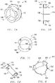
FIG. 2 includes a perspective view of a bearing in accordance with an embodiment. -
FIG. 3 includes a top view of the bearing in accordance with an embodiment. -
FIG. 4 includes a plan view of a structure having an opening including arcuate relief portions adapted to receive the bearing in accordance with an embodiment. -
FIG. 5 includes a plan view of a structure having an opening including polygonal relief portions adapted to receive the bearing in accordance with an embodiment. -
FIG. 6 includes a perspective view of an alignment tool adapted to rotate the bearing in accordance with an embodiment. -
FIG. 7A includes a perspective view of a bearing in accordance with an embodiment. -
FIG. 7B includes a side cross-sectional view of a bearing in accordance with an embodiment. -
FIG. 7C includes a top view of a bearing in accordance with an embodiment. -
FIG. 7D includes a side cross-sectional view of a bearing in accordance with an embodiment. -
FIG. 8 includes a perspective view of a structure having an opening including arcuate relief portions adapted to receive the bearing in accordance with an embodiment. - Skilled artisans appreciate that elements in the figures are illustrated for simplicity and clarity and have not necessarily been drawn to scale. For example, the dimensions of some of the elements in the figures may be exaggerated relative to other elements to help to improve understanding of embodiments of the invention.
- The following description in combination with the figures is provided to assist in understanding the teachings disclosed herein. The following discussion will focus on specific implementations and embodiments of the teachings. This focus is provided to assist in describing the teachings and should not be interpreted as a limitation on the scope or applicability of the teachings. However, other embodiments can be used based on the teachings as disclosed in this application.
- The terms "comprises," "comprising," "includes," "including," "has," "having" or any other variation thereof, are intended to cover a non-exclusive inclusion. For example, a method, article, or apparatus that comprises a list of features is not necessarily limited only to those features but may include other features not expressly listed or inherent to such method, article, or apparatus. Further, unless expressly stated to the contrary, "or" refers to an inclusive-or and not to an exclusive-or. For example, a condition A or B is satisfied by any one of the following: A is true (or present) and B is false (or not present), A is false (or not present) and B is true (or present), and both A and B are true (or present).
- Also, the use of "a" or "an" is employed to describe elements and components described herein. This is done merely for convenience and to give a general sense of the scope of the invention. This description should be read to include one, at least one, or the singular as also including the plural, or vice versa, unless it is clear that it is meant otherwise. For example, when a single item is described herein, more than one item may be used in place of a single item. Similarly, where more than one item is described herein, a single item may be substituted for that more than one item.
- Unless otherwise defined, all technical and scientific terms used herein have the same meaning as commonly understood by one of ordinary skill in the art to which this invention belongs. The materials, methods, and examples are illustrative only and not intended to be limiting. To the extent not described herein, many details regarding specific materials and processing acts are conventional and may be found in textbooks and other sources within the bearing arts.
- The invention is defined by a bearing according to claim 1 and a method of installing a bearing according to claim 3. In a particular embodiment, the generally cylindrical sidewall can include a substrate coupled to the low friction material.
- Referring initially to
FIGs. 1 to 3 , abearing 100 in accordance with one or more of the embodiments described herein includes a generallycylindrical sidewall 102 defining a firstaxial end 104 and a secondaxial end 106. Anaperture 108 extends at least partially, such as entirely, between the first and secondaxial ends bearing 100 includes agap 110 extending between the first and secondaxial ends gap 110 can be open such that circumferential ends of thebearing 100 are spaced apart from one another. In another embodiment, thegap 110 can be closed such as, for example, by an adhesive, a weld, a mechanical fastener or deformation, or any other suitable method recognized by skilled artisans. - A
flange 112 extends radially from the generallycylindrical sidewall 102. In an embodiment, theflange 112 extends radially inward. In another embodiment, theflange 112 extends radially outward. In yet a further embodiment, theflange 112 can extend both radially inward and radially outward. In an embodiment, theflange 112 is disposed at a location proximate the firstaxial end 104 of thebearing 100. In a more particular embodiment, theflange 112 is disposed at the firstaxial end 104 such that no portion of thebearing 100 extends beyond theflange 112. In an embodiment, theflange 112 has asurface 116 and asurface 118 opposite thesurface 116. Thesurface 116 can be disposed closer to the firstaxial end 104 of thebearing 100 than thesurface 118. - A
feature 114 extends radially from the generallycylindrical sidewall 102 at a location between theflange 112 and the secondaxial end 106 of thebearing 100. Thefeature 114 can be a projection, a tine, an elongated wave structure, a dimple, a ridge, a corrugation, or another suitable element extending from the generallycylindrical sidewall 102. By way of non-limiting example, thefeature 114 can be formed by stamping, pressing, milling, machining, grinding, ablating, deposition, lamination, adhesion, another operating procedure, or any combination thereof. In an embodiment, thefeature 114 is unitary with the generallycylindrical sidewall 102. In another embodiment, thefeature 114 is not unitary with the generallycylindrical sidewall 102. For example, thefeature 114 can be fixedly coupled to the generallycylindrical sidewall 102. In a particular embodiment, an artifact (not illustrated) can occur where thefeature 114 is located along the generallycylindrical sidewall 102. For example, features 114 that are pressed radially outward into the generallycylindrical sidewall 102 may form a corresponding recess along the radially inner side of the generallycylindrical sidewall 102. In an embodiment, as illustrated inFIG. 1 , thefeature 114 can have an arcuate profile, as viewed in cross section. In another embodiment, as illustrated inFIG. 2 , thefeature 114 can have a polygonal profile, as viewed in cross section. In a particular embodiment, thefeature 114 can have a square profile, as viewed in cross section. In yet a further embodiment, thefeature 114 can include arcuate segments and polygonal segments, as viewed in cross section. - In an embodiment, the
feature 114 can extend from the generallycylindrical sidewall 102 in a direction generally perpendicular thereto. For example, thefeature 114 can have a side surface which is perpendicular, or generally perpendicular, to the generallycylindrical sidewall 102 at the location from which thefeature 114 extends from. In another embodiment, thefeature 114 can have a side surface canted relative to the generallycylindrical sidewall 102. For example, the feature sidewall can be disposed at an angle, as measured with respect to the generallycylindrical sidewall 102, greater than 90°, greater than 100°, greater than 110°, greater than 120°, greater than 130°, greater than 140°, or greater than 150°. - In an embodiment, the
feature 114 includes a plurality of features. For example, the plurality offeatures 114 can include at least 2 features 114, at least 5 features 114, at least 10features 114, at least 25features 114, or at least 50 features 114. In another embodiment the plurality offeatures 114 includes no greater than 100 features. The plurality offeatures 114 can be spaced apart from one another. In an embodiment, the plurality offeatures 114 are equally spaced apart from one another as measured around a circumference of the generallycylindrical sidewall 102. - In an embodiment, the feature or features 114 extends in a same radial direction as the
flange 112. For example, theflange 112 and feature 114 can both extend radially inward or can both extend radially outward. In another embodiment, thefeature 114 extends in a different radial direction as compared to theflange 112. For example, theflange 112 can extend radially inward and the feature can extend radially outward. As illustrated inFIG. 1 , theflange 112 and feature 114 both extend radially outward. As described in greater detail below, thefeature 114 may be particularly suitable for securing thebearing 100 to a structure. - In a particular instance, the
flange 112 is spaced apart from thefeature 114 by a distance, D, less than an axial height, HB, of the generallycylindrical sidewall 102. The distance, D, is measured from thesurface 118 of theflange 112 to a nearest point of thefeature 114. In an embodiment, D is less than HB, such as no greater than 0.99 HB, no greater than 0.95 HB, no greater than 0.9 HB, no greater than 0.85 HB, no greater than 0.8 HB, no greater than 0.75 HB, or no greater than 0.5 HB. In another embodiment, D is no less than 0.01 HB, no less than 0.05 HB, or no less than 0.1 HB. - The
flange 112 can extend a maximum radial dimension, RF, as measured from an outermost surface of the generallycylindrical sidewall 102 to an outermost location of theflange 112. Thefeature 114 can extend a distance, DF, as measured from an outermost surface of the generallycylindrical sidewall 102. In an embodiment, RF is different than DF. For example, in an embodiment, RF is greater than DF, such as wherein RF is at least 1.01 DF, at least 1.05 DF, at least 1.1 DF, at least 1.2 DF, at least 1.3 DF, at least 1.4 DF, at least 1.5 DF, or at least 1.75 DF. In another embodiment, RF is less than DF, such as wherein RF is no greater than 0.99 DF, no greater than 0.95 DF, no greater than 0.9 DF, no greater than 0.75 DF, no greater than 0.5 DF, or no greater than 0.25 DF. In a particular embodiment, RF is uniform as measured around the circumference of theflange 112. In another embodiment, theflange 112 can have a non uniform radial dimension. - According to the claimed invention, an
engagement feature 120 is formed in theflange 112. In an embodiment, theengagement feature 120 can include acutout 122 extending from the outermost surface of theflange 112 toward a central axis of the generallycylindrical sidewall 102. In a more particular embodiment,cutout 122 can extend at least 0.01 RF, at least 0.1 RF, at least 0.5 RF, or at least 0.9 RF as measured in a direction parallel with RF. - In an embodiment, the
cutout 122 has a polygonal shape, when viewed parallel with the central axis of the generallycylindrical sidewall 102. In another embodiment, thecutout 122 has an arcuate shape when viewed parallel with the central axis of the generallycylindrical sidewall 102. In yet a further embodiment, thecutout 122 has a combination of polygonal portions and arcuate portions. - In an embodiment, the
flange 112 has a thickness, TF, or average thickness in the case of a flange with varying thickness, which is no greater than the thickness of thecutout 122. In another embodiment, the cutout extends at least 0.01 TF, at least 0.1 TF, at least 0.25 TF, at least 0.5 TF, at least 0.75 TF, or at least 0.9 TF. In a further embodiment, thecutout 122 extends through the entire thickness, TF, of theflange 112. - The
cutout 122 can have a first circumferential dimension, as measured from a top view at a radially innermost portion of thecutout 122, and a second circumferential dimension, as measured from a top view at a radially outermost portion of thecutout 122. In an embodiment, the first circumferential dimension is different than the second circumferential dimension. In a more particularly embodiment, the second circumferential dimension is greater than the first circumferential dimension. For example, the second circumferential dimension can be at least 1.01 times greater than the first circumferential dimension, at least 1.1 times greater than the first circumferential dimension, at least 1.2 times greater than the first circumferential dimension, at least 1.3 times greater than the first circumferential direction, at least 1.4 times greater than the first circumferential dimension, at least 1.5 times greater than the first circumferential direction, or at least 2 times greater than the first circumferential dimension. In an embodiment, the second circumferential dimension is no greater than 1000 times greater than the first circumferential dimension, no greater than 100 times greater than the first circumferential dimension, or no greater than 10 times greater than the first circumferential dimension. - According to the claimed invention, the
engagement feature 120 comprises a projecting element, a corrugation, a ridge, a dimple, or a tine projecting from the flange (112). The engagement feature can also be another element projecting from theflange 112, or any combination thereof. - In a particular embodiment, the
engagement feature 120 includes a plurality of features, such as at least two engagement features, at least three engagement features, at least four engagement features, at least five engagement features, at least ten engagement features, or at least fifty engagement features. In another embodiment, the plurality of engagement features 120 includes no greater than 1000 engagement features, no greater than 500 engagement features, or no greater than 100 engagement features. In a particular embodiment, at least two of the plurality of engagement features 120 have a generally same size, a generally same shape, or a generally same size and a generally same shape, as compared to one another. The plurality of engagement features can be spaced apart around the circumference of theflange 112. In an embodiment, the engagement features 120 are equally spaced apart from one another around a circumference of theflange 120. In a particular embodiment, at least one of the engagement features 120 can be circumferentially aligned with thegap 110. - According to the claimed invention, the generally cylindrical sidewall (102) comprises a low friction material (126). In an embodiment, the generally
cylindrical sidewall 102 can include asubstrate 124 and alow friction material 126 coupled to thesubstrate 124. Thesubstrate 124 can be coupled to thelow friction material 126 by an adhesive, a primer layer, mechanical deformation, lamination, or any other suitable method. In an embodiment, thesubstrate 124 can include a resilient material. In a particular embodiment, thelow friction material 126 is disposed along an inner surface of the generallycylindrical sidewall 102. Thelow friction material 126 can extend onto at least a portion, such as all, of thesurface 116 of theflange 112. In another particular embodiment, thelow friction material 126 can be disposed along an outer surface of the generallycylindrical sidewall 102. Thelow friction material 126 can extend onto at least a portion, such as all, of thesurface 118 of theflange 118. - By way of a non-limiting example, the
substrate 124 can include a metal or an alloy such as steel. - The
low friction material 126 can include a material having a relatively low coefficient of friction. Exemplary materials include polymers, such as for example, a polyketone, a polyaramid, a polyimide, a polyetherimide, a polyamideimide, a polyphenylene sulfide, a polyphenylene sulfone, a fluoropolymer, a polybenzimidazole, a derivation thereof, or even a combination thereof. In a particular embodiment, thelow friction material 126 can at least partially include, or consist essentially of a polymer, such as a polyketone, a thermoplastic polyimide, a polyetherimide, a polyphenylene sulfide, a polyether sulfone, a polysulfone, a polyamideimide, a derivative thereof, or even a combination thereof. In a further embodiment, thelow friction material 126 can include a polyketone, such as polyether ether ketone (PEEK), polyether ketone, polyether ketone ketone, polyether ketone ether ketone, a derivative thereof, or even a combination thereof. - Fluoropolymers are used according to a particular embodiment. Exemplary fluoropolymers include fluorinated ethylene propylene (FEP), polytetrafluoroethylene (PTFE), polyvinylidene fluoride (PVDF), perfluoroalkoxy (PFA), a terpolymer of tetrafluoroethylene, hexafluoropropylene, and vinylidene fluoride (THV), polychlorotrifluoroethylene (PCTFE), ethylene tetrafluoroethylene copolymer (ETFE), ethylene chlorotrifluoroethylene copolymer (ECTFE), or any combination thereof.
- In certain embodiments, the
low friction material 126 can include one or more filler materials. Exemplary filler materials include glass fibers, carbon fibers, silicon, PEEK, aromatic polyester, carbon particles, bronze, fluoropolymers, thermoplastic fillers, aluminum oxide, polyamidimide (PAI), PPS, polyphenylene sulfone (PPSO2), LCP, aromatic polyesters, molybdenum disulfide, tungsten disulfide, graphite, grapheme, expanded graphite, boron nitrade, talc, calcium fluoride, or any combination thereof. Additionally, the filler material can include alumina, silica, titanium dioxide, calcium fluoride, boron nitride, mica, Wollastonite, silicon carbide, silicon nitride, zirconia, carbon black, pigments, or any combination thereof. -
FIGs. 4 and5 illustrate astructure 300 including anopening 302 defining arelief portion 304. By way of non-limiting example, thestructure 300 can include a substrate, a tubular, a wall, or a sheet. Thestructure 300 can have a thickness, TS that is slightly less than the distance, D, between thefeature 114 and theflange 112. In an embodiment, TS is no less than 0.85 D, no less than 0.9 D, no less than 0.95 D, no less than 0.96 D, no less than 0.97 D, no less than 0.98 D, or no less than 0.99 D. In another embodiment, TS is no greater than 1.5 D, no greater than 1.3 D, no greater than 1.1 D, no greater than 1.05 D, or no greater than 1.01 D. - In an embodiment, the
structure 300 can have varying thickness. For example, a thickness at first location along the circumference of theopening 302 can be greater than a thickness at a second location along the circumference of theopening 302. To compensate for variable thickness, the bearing 100 can havemultiple features 114 each having a different spatial arrangement with respect to theflange 112. - In another embodiment, the bearing 100 can include a plurality of
features 114 at different distances, D, from the flange to permit engagement of the bearing 100 with structures of different thicknesses. For example, the bearing 100 can include afirst feature 114 spaced apart from the flange by a first distance and asecond feature 114 spaced apart from the flange by a second distance. Thefirst feature 114 can secure thebearing 100 to astructure 300 with a first thickness and thesecond feature 114 can secure thebearing 100 to astructure 300 with a second thickness. In such a manner, onesized bearing 100 can be used in a range of applications having different dimensional requirements. In a number of embodiments, as shown inFigs. 7A-8 , at least onefeature 114 may secure thebearing 100 to thestructure 300 by providing a matching interface with arelief portion 304 of thestructure 300. In a number of embodiments, the at least onefeature 114 may be a square notch that matches arelief portion 304 in the form of a cylindrical projection or opening. In a number of embodiments, at least oneengagement feature 120 may secure thebearing 100 to thestructure 300 by providing a matching interface with arelief portion 304 of thestructure 300. In a number of embodiments, the at least oneengagement feature 120 may be a dimple located on asurface flange 112 that matches arelief portion 304 in the form of a cylindrical projection or opening. In a number of embodiments, turning thebearing 100 while sitting in arelief portion 304 may create axial pressure between theengagement feature 120 and thefeature 114 such that thebearing 100 may be locked without asecond flange 112 on thebearing 100 required. - The
relief portion 304 can be in open communication with theopening 302 and extend radially outward therefrom. Therelief portion 304 can be adapted to receive thefeature 114. As illustrated inFIG. 4 , at least onerelief portion 304 can have an arcuate shape, from a plan view. As illustrated inFIG. 5 , at least onerelief portion 304 can have an polygonal shape, from a plan view. In an embodiment, therelief portion 304 includes a plurality of relief portions spaced apart around a circumference of theopening 302. In an embodiment, therelief portions 304 can be spaced apart equally around the circumference of theflange 112. In a particular embodiment, the plurality ofrelief portions 304 can include at least 2 relief portions, at least 3 relief portions, at least 4 relief portions, at least 5 relief portions, or at least 10 relief portions. In another embodiment, the plurality ofrelief portions 304 includes no greater than 100 relief portions, no greater than 50 relief portions, or no greater than 25 relief portions. - As illustrated in
FIGs. 4 and5 , therelief portion 304 can include afirst relief portion 306 and asecond relief portion 308. The first andsecond relief portions opening 302 has a first diameter, D1, as measured between opposite ends of theopening 302 and a second diameter, D2 measured by a distance between two radially outermost surfaces of the first andsecond relief portions - The
opening 302 can define a circumference, Co, and the relief portion can define a circumferential width, CRP, as measured along the circumference of the opening, that is less than CO. In an embodiment, CRP is in a range of 0.1 CO to 0.99 CO, in a range of 0.2 CO to 0.9 CO, or in a range of 0.3 CO to 0.8 CO. -
FIG. 6 illustrates analignment tool 400 including abody 402 and acomplementary engagement feature 404 disposed on thebody 402. Thealignment tool 400 can engage with the engagement features 120 on thebearing 100 such that a user can rotate thebearing 100 through thealignment tool 400. In an embodiment, thecomplementary engagement feature 404 has a shape similar to theengagement feature 120. For example, as illustrated, thecomplementary engagement feature 404 can include a generally triangular projection adapted to be received in the triangular cutouts of thebearing 100. Thebody 402 can extend away from thecomplementary engagement feature 404, permitting a user to grasp thealignment tool 400 to rotate thebearing 100. - In an embodiment, the
body 402 has a generallycylindrical sidewall 406 and opposite axial ends 408 and 410. Thecomplementary engagement feature 404 can be disposed proximate to one of the opposite axial ends 408 or 410. Aprojection 412 can extend from thebody 402 and fit within theaperture 108 of thebearing 100. In an embodiment, theprojection 412 is disposed between the complementary engagement features 404. Theprojection 412 can have a diameter less than or generally equal to the diameter of theaperture 108. Theprojection 412 permits smoother engagement between thealignment tool 400 and thebearing 100 by allowing a user to more easily position and align thealignment tool 400 relative to theaperture 108 and engagement features 120. - In an embodiment, the
alignment tool 400 can be powered. That is, thealignment tool 400 can include an urging element adapted to rotate thecomplementary engagement feature 404. In another embodiment, thealignment tool 400 can be adapted to be connected to a power tool. In a further embodiment, thealignment tool 400 is adapted to be manually operated. - In certain embodiments, the
alignment tool 400 can include an encoding element (not illustrated) adapted to determine the relative rotational position of the alignment tool 400 (e.g., the complementary engagement features 404). In a particular embodiment, the encoding element or another sensor can sense a rotational position of the alignment tool before application of torque on thebearing 100 and after application of torque on thebearing 100. - Referring again to
FIG. 1 , the bearing 100 can be positioned on thestructure 300 at a location adjacent to theopening 302. The bearing 100 can then be at least partially inserted into theopening 302 such that the secondaxial end 106 extends at least partially into theopening 302. After aligning thefeature 114 with therelief portion 304, the bearing 100 can be inserted into theopening 302 until thesurface 118 of the bearing 100 contacts a surface of thestructure 300. Thealignment tool 400 can then be aligned with the bearing 100 such that thecomplementary engagement feature 404 of thealignment tool 400 is aligned with theengagement feature 120 of the bearing. Thealignment tool 400 can then be used to rotate thebearing 100 within theopening 302 until thefeature 114 is not disposed in axial alignment with therelief portion 304. - In an embodiment, the
bearing 100 is adapted to be installed in theopening 302 in a first rotational orientation. In the first rotational orientation thefeature 114 of thebearing 100 is aligned with therelief portion 304. After initial installation within theopening 302, the bearing can be rotated to a second rotational orientation different from the first rotational orientation. The second rotational orientation of thebearing 100 puts thefeature 114 at a location spaced apart from therelief portion 304 such that the bearing 100 cannot be pulled axially from theopening 302 without at least partially rotating thebearing 100. In an embodiment, the first rotational orientation is different from the second rotational orientation by at least 1°, at least 5°, at least 10°, at least 20°, at least 30°, at least 40°, at least 50°, at least 60°, at least 70°, at least 80°, or at least 90°. In another embodiment, the first rotational orientation is different from the second rotational orientation by less than 360°, less than 270°, less than 180°, or less than 91°. The rotational difference between the first rotational orientation and second rotational orientation is largely determined by the arrangement ofrelief portions 304. A greater number ofrelief portions 304 may result in a lesser difference in rotational orientation between the first and second rotational orientations. - Note that not all of the activities described above in the general description or in the examples are required, that a portion of a specific activity may not be required, and that one or more further activities may be performed in addition to those described. Still further, the order in which activities are listed is not necessarily the order in which they are performed.
- Certain features that are, for clarity, described herein in the context of separate embodiments, may also be provided in combination in a single embodiment. Conversely, various features that are, for brevity, described in the context of a single embodiment, may also be provided separately or in any subcombination. Further, reference to values stated in ranges includes each and every value within that range.
- Benefits, other advantages, and solutions to problems have been described above with regard to specific embodiments. However, the benefits, advantages, solutions to problems, and any feature(s) that may cause any benefit, advantage, or solution to occur or become more pronounced are not to be construed as a critical, required, or essential feature of any or all the embodiments.
- The specification and illustrations of the embodiments described herein are intended to provide a general understanding of the structure of the various embodiments. The specification and illustrations are not intended to serve as an exhaustive and comprehensive description of all of the elements and features of apparatus and systems that use the structures or methods described herein. Separate embodiments may also be provided in combination in a single embodiment, and conversely, various features that are, for brevity, described in the context of a single embodiment, may also be provided separately or in any subcombination. Further, reference to values stated in ranges includes each and every value within that range. Many other embodiments may be apparent to skilled artisans only after reading this specification. Other embodiments may be used and derived from the disclosure within the scope of the appended claims.
Claims (14)
- A bearing (100) comprising:a generally cylindrical sidewall (102) defining first and second axial ends (104, 106) and an aperture (108) extending between the first and second axial ends (104, 106), and a gap (110) extending between the first and the second axial ends (104, 106);a flange (112) extending radially from the generally cylindrical sidewall (102) at a location proximate the first axial end (104); anda feature (114) extending radially from the generally cylindrical sidewall (102) at a location disposed between the flange (112) and the second axial end (106),wherein the generally cylindrical sidewall (102) comprises a low friction material (126), andwherein the flange (112) comprises an engagement feature (120) circumferentially offset from the gap (110),wherein the engagement feature (120) comprises a projecting element, a corrugation, a ridge, a dimple, or a tine projecting from the flange (112).
- An assembly comprising:a structure (300) having an opening (302) with a relief portion (304); anda bearing (100) according to claim 1.
- A method of installing a bearing (100) comprising:providing a bearing (100) according to claim 1;aligning the bearing (100) with a surface having an opening (302) with a relief portion (304) at a circumferential location corresponding to the feature (114);inserting the bearing (100) into the opening such that the feature (114) passes through the relief portion (304);urging the bearing (100) into the opening until the flange (112) contacts the surface; androtating the bearing (100) until the feature (114) is angularly offset from the relief portion (304).
- The bearing (100), assembly, or method of any of claims 1-3, wherein the generally cylindrical sidewall (102) comprises a substrate (124) and a low friction material (126), and wherein the low friction material (126) is coupled to the substrate (124).
- The bearing (100) , assembly, or method of claim 4, wherein the feature (114) extends radially outward from the generally cylindrical sidewall (102), and wherein the low friction material (126) is disposed along an inner surface of the generally cylindrical sidewall (102).
- The bearing (100), assembly, or method of any of claims 1-3, wherein the flange (112) is disposed at the first axial end (104) of the bearing (100).
- The bearing (100), assembly, or method of any of claims 1-3, wherein the flange (112) is spaced apart from the feature (114) by a distance, D, wherein the generally cylindrical sidewall (102) has an axial height, HB, and wherein D is less than HB, such as wherein D is no greater than 0.99 HB, no greater than 0.95 HB, no greater than 0.9 HB, no greater than 0.85 HB, no greater than 0.8 HB, no greater than 0.75 HB, or no greater than 0.5 HB, and wherein D is no less than 0.01 HB, no less than 0.05 HB, or no less than 0.1 HB.
- The bearing (100), assembly, or method of any of claims 1-3, wherein the flange (112) and feature (114) extend in a same radial direction as one another, such as wherein the flange (112) and feature (114) both extend radially outward from the generally cylindrical sidewall (102).
- The bearing (100), assembly, or method of any of claims 1-3, wherein the flange (112) has a first surface and a second surface opposite the first surface, wherein the first surface is closer to the first axial end (104) than the second surface, and wherein the first surface comprises a low friction material (126).
- The bearing (100), assembly, or method of any of claims 1-3, wherein the flange (112) extends a maximum radial dimension, RF, as measured from an outermost surface of the generally cylindrical sidewall (102), wherein the feature (114) extends a distance, DF, as measured from an outermost surface of the generally cylindrical sidewall (102), and wherein RF and DF are different from one another.
- The bearing (100), assembly, or method of claim 10, wherein RF is greater than DF, such as wherein RF is at least 1.01 DF, at least 1.05 DF, at least 1.1 DF, at least 1.2 DF, at least 1.3 DF, at least 1.4 DF, at least 1.5 DF, or at least 1.75 DF.
- The bearing (100), assembly, or method of claim 10, wherein RF is less than DF, such as wherein RF is no greater than 0.99 DF, no greater than 0.95 DF, no greater than 0.9 DF, no greater than 0.75 DF, no greater than 0.5 DF, or no greater than 0.25 DF.
- The bearing (100), assembly, or method of any one of claims 10-12, wherein RF is uniform around the circumference of the flange (112).
- The bearing (100), assembly, or method of any of claims 1-3, wherein the engagement feature (120) comprises a cutout (122) extending from an outermost surface of the flange (112) toward a central axis of the generally cylindrical sidewall (102).
Applications Claiming Priority (2)
| Application Number | Priority Date | Filing Date | Title |
|---|---|---|---|
| US201662370021P | 2016-08-02 | 2016-08-02 | |
| PCT/US2017/044800 WO2018026756A1 (en) | 2016-08-02 | 2017-08-01 | Bearing |
Publications (3)
| Publication Number | Publication Date |
|---|---|
| EP3494316A1 EP3494316A1 (en) | 2019-06-12 |
| EP3494316A4 EP3494316A4 (en) | 2020-07-01 |
| EP3494316B1 true EP3494316B1 (en) | 2022-06-01 |
Family
ID=61069036
Family Applications (1)
| Application Number | Title | Priority Date | Filing Date |
|---|---|---|---|
| EP17837500.2A Active EP3494316B1 (en) | 2016-08-02 | 2017-08-01 | Bearing |
Country Status (10)
| Country | Link |
|---|---|
| US (1) | US10309456B2 (en) |
| EP (1) | EP3494316B1 (en) |
| JP (1) | JP6802898B2 (en) |
| KR (4) | KR20190019217A (en) |
| CN (1) | CN109477519B (en) |
| CA (1) | CA3032659C (en) |
| ES (1) | ES2924258T3 (en) |
| MX (1) | MX2019000876A (en) |
| PL (1) | PL3494316T3 (en) |
| WO (1) | WO2018026756A1 (en) |
Families Citing this family (9)
| Publication number | Priority date | Publication date | Assignee | Title |
|---|---|---|---|---|
| USD864691S1 (en) * | 2016-06-14 | 2019-10-29 | Christian Campos | Front and rear engine cover alignment tool and seal installer |
| US10309456B2 (en) | 2016-08-02 | 2019-06-04 | Saint-Gobain Performance Plastics Corporation | Bearing |
| MX2021006720A (en) * | 2018-12-22 | 2021-07-15 | Saint Gobain Performance Plastics Corp | Bearing assembly for tracker assembly and methods of making and using the same. |
| TWI764109B (en) * | 2019-03-22 | 2022-05-11 | 美商聖高拜塑膠製品公司 | Composite bearing and method of making and using the same |
| DE102019209027A1 (en) * | 2019-06-21 | 2020-12-24 | Siemens Aktiengesellschaft | Bearing arrangement |
| MX2022005331A (en) * | 2019-11-08 | 2022-05-26 | Saint Gobain Performance Plastics Corp | Split bearing, assembly, and method of making and using the same. |
| CN114761695B (en) * | 2019-12-06 | 2024-04-09 | 美国圣戈班性能塑料公司 | Flanged bearing, assembly, and methods of making and using the same |
| DE102020208107A1 (en) | 2020-06-30 | 2021-12-30 | Robert Bosch Gesellschaft mit beschränkter Haftung | Rotary bearing device and material analysis device with rotary bearing device |
| WO2022221868A1 (en) | 2021-04-16 | 2022-10-20 | Saint-Gobain Performance Plastics Corporation | Bearing assembly for tracker assembly and methods of making and using the same |
Citations (3)
| Publication number | Priority date | Publication date | Assignee | Title |
|---|---|---|---|---|
| US20120240350A1 (en) * | 2011-03-22 | 2012-09-27 | Saint-Gobain Performance Plastics Pampus Gmbh | Bushing with transfigurable electrical conduction state |
| US20140246266A1 (en) * | 2011-10-18 | 2014-09-04 | Nsk Ltd. | Steering column support apparatus |
| CN204458837U (en) * | 2014-10-28 | 2015-07-08 | 安徽汉升新金属技术有限公司 | A kind of lining |
Family Cites Families (227)
| Publication number | Priority date | Publication date | Assignee | Title |
|---|---|---|---|---|
| US259948A (en) | 1882-06-20 | Tille | ||
| US503609A (en) | 1893-08-22 | Peder lobben | ||
| US413525A (en) | 1889-10-22 | Anti-friction bearing for vehicle-wheels | ||
| US590322A (en) | 1897-09-21 | Spindle-bearing | ||
| US231866A (en) | 1880-08-31 | taylor | ||
| US2761202A (en) * | 1956-09-04 | R beare | ||
| US447531A (en) | 1891-03-03 | andrews | ||
| US548651A (en) | 1895-10-29 | Spindle-bearing for spinning-machines | ||
| US616094A (en) | 1898-12-20 | The norp | ||
| US389819A (en) | 1888-09-18 | Roller-bearing for axles and shafts | ||
| US1325849A (en) | 1919-12-23 | hoover | ||
| US664946A (en) | 1900-03-21 | 1901-01-01 | Adolph Haenichen | Shaft-bearing. |
| US917522A (en) | 1907-10-03 | 1909-04-06 | Alstyne Loucks Van | Car-bearing. |
| US1151847A (en) | 1909-08-27 | 1915-08-31 | Werner Ahrens | Antifriction-bearing. |
| US1091830A (en) | 1910-02-14 | 1914-03-31 | Isaac A George | Bearing. |
| US1182188A (en) | 1911-07-17 | 1916-05-09 | James J Mcgowan | Bearing for pin-cylinders. |
| US1029075A (en) | 1911-08-10 | 1912-06-11 | Hyatt Roller Bearing Co | Collared spirally-wound roll. |
| US1197006A (en) | 1916-04-26 | 1916-09-05 | New Britain Machine Co | Buffing-machine. |
| US1346121A (en) | 1916-05-09 | 1920-07-13 | Andrew Albright Jr | Bearing |
| US1327301A (en) | 1918-10-09 | 1920-01-06 | James B Watson | Bearing |
| US1648441A (en) | 1920-08-18 | 1927-11-08 | Elbert O Brower | Machine element |
| US1526632A (en) | 1922-08-21 | 1925-02-17 | Fischbach Paul | Shackle |
| US1615499A (en) | 1926-05-11 | 1927-01-25 | Charlie J Angell | One-way disk plow |
| US1759149A (en) | 1926-09-27 | 1930-05-20 | Delta Star Electric Co | Rotary insulator |
| US1790253A (en) | 1927-02-09 | 1931-01-27 | Harold J Clark | Crank-shaft and bearing assembly |
| US1904203A (en) | 1928-04-11 | 1933-04-18 | Celanese Corp | Bearing and application thereof |
| US1910300A (en) * | 1928-05-07 | 1933-05-23 | Gemmer Mfg Co | Bushing for motor car steering columns |
| US1738037A (en) * | 1928-05-21 | 1929-12-03 | Warner Corp | Spring bushing |
| US1882102A (en) | 1929-04-27 | 1932-10-11 | Nomy Ab | Shaft bearing |
| US1998888A (en) | 1930-03-05 | 1935-04-23 | Nomy Ab | Bearing |
| US2016757A (en) | 1931-05-14 | 1935-10-08 | Trayer Bolt Company Inc | Wear compensating bearing |
| US2043790A (en) | 1932-01-08 | 1936-06-09 | Wagner Electric Corp | Thrust washer assembly |
| US2019564A (en) | 1932-05-27 | 1935-11-05 | Apex Electrical Mfg Co | Laundry machine mechanism |
| US2074203A (en) | 1932-11-28 | 1937-03-16 | Benedek Elek | Pump |
| US1947066A (en) | 1932-12-14 | 1934-02-13 | Samuel M Langston Co | Corrugator |
| US2103895A (en) | 1933-03-13 | 1937-12-28 | Herbert S Simpson | Muller |
| US2006404A (en) | 1934-01-10 | 1935-07-02 | Western Electric Co | Material handling apparatus |
| US2145864A (en) | 1934-07-12 | 1939-02-07 | Ohio Crankshaft Co | Method of making hardened surface articles |
| US2088937A (en) | 1934-09-21 | 1937-08-03 | Walworth Patents Inc | Valve |
| US2174261A (en) | 1935-03-20 | 1939-09-26 | Packard Motor Car Co | Gear mounting |
| US2113167A (en) | 1935-09-09 | 1938-04-05 | B B B Corp | Water pump seal |
| US2124132A (en) * | 1936-03-24 | 1938-07-19 | Glacier Co Ltd | Manufacture of bearings |
| US2182012A (en) | 1937-01-07 | 1939-12-05 | Baird Machine Co | Spindle |
| US2182247A (en) | 1937-01-19 | 1939-12-05 | Globe Oil Tools Co | Well bit construction |
| US2126039A (en) | 1937-03-08 | 1938-08-09 | Chicago Pneumatic Tool Co | Earth boring drill |
| US2266140A (en) | 1939-04-15 | 1941-12-16 | Singer Mfg Co | Chain-stitch sewing machine |
| US2259447A (en) | 1939-06-05 | 1941-10-21 | Symington Gould Corp | Journal box assembly |
| US2283939A (en) | 1939-10-19 | 1942-05-26 | Rudolph W Miller | Journal lubricator |
| US2306048A (en) | 1939-11-17 | 1942-12-22 | Fast Bearing Company | Combined radial and thrust bearing unit |
| US2226524A (en) | 1939-11-21 | 1940-12-24 | S K F Ind Inc | Means for securing a bearing to a shaft |
| US2350272A (en) | 1940-06-22 | 1944-05-30 | Gen Motors Corp | Spindle |
| US2440890A (en) | 1941-01-03 | 1948-05-04 | Turbo Engineering Corp | Turbine bearing |
| US2331652A (en) | 1941-04-30 | 1943-10-12 | Timken Axle Co Detroit | Brake mechanism |
| US2309397A (en) | 1941-05-21 | 1943-01-26 | Illmer Louis | Protective journal bearing means |
| US2358510A (en) * | 1942-01-09 | 1944-09-19 | Holland Co | Spring snubber unit |
| US2369684A (en) | 1942-01-13 | 1945-02-20 | Bliss E W Co | Rolling mill construction |
| US2404429A (en) | 1943-01-02 | 1946-07-23 | Gen Motors Corp | Railway journal box |
| US2424757A (en) | 1945-06-06 | 1947-07-29 | Jr Ferdinand Klumpp | Self-locking bushing |
| US2474489A (en) | 1946-02-07 | 1949-06-28 | Beloit Iron Works | Rocker mounting for rotary bearings |
| US2608448A (en) | 1946-03-29 | 1952-08-26 | Toledo Scale Co | Knife edge pivot construction |
| US2631905A (en) | 1946-08-06 | 1953-03-17 | Nat Lead Co | Bearing surface |
| US2436274A (en) | 1946-09-14 | 1948-02-17 | Colin S Watt | Bearing |
| US2530520A (en) | 1946-09-17 | 1950-11-21 | Everel Propeller Corp | Propeller hub |
| US2575830A (en) | 1947-03-20 | 1951-11-20 | Morgan Construction Co | Thrust bearing |
| US2652296A (en) | 1948-09-03 | 1953-09-15 | Skf Ind Inc | Multirow cylindrical roller bearing |
| US2693965A (en) | 1948-10-28 | 1954-11-09 | James W Briney | Adjustable coupling |
| US2557813A (en) | 1948-12-07 | 1951-06-19 | Edward F Burton | Method and apparatus for preparing frozen confections |
| US2638388A (en) | 1949-04-11 | 1953-05-12 | Baker Perkins Ltd | Adjustment means for the rolls of multiroll chocolate and like refining machines |
| US2614897A (en) | 1950-03-11 | 1952-10-21 | West Bend Aluminum Co | Main bearing for multicrank engines |
| US2668316A (en) * | 1950-08-29 | 1954-02-09 | Chrysler Corp | Bushing |
| US2665176A (en) | 1951-10-26 | 1954-01-05 | Int Harvester Co | Bearing |
| US2685483A (en) | 1952-09-03 | 1954-08-03 | Joseph E Morra | Shaft bearing |
| US2719064A (en) | 1952-12-11 | 1955-09-27 | John R Barnard | Conical self-adjusting bearing |
| US2765657A (en) | 1953-01-28 | 1956-10-09 | Karl L Schaus | Drive shaft journaling mechanism for gas meters |
| US3058786A (en) | 1956-02-03 | 1962-10-16 | Aerojet General Co | Composite bearing |
| US2861850A (en) | 1956-03-16 | 1958-11-25 | Abell Howe Company | Wheel and axle assembly |
| LU35574A1 (en) | 1956-09-12 | |||
| US3159045A (en) | 1957-04-19 | 1964-12-01 | Gen Motors Corp | Drive mechanism |
| US2991134A (en) | 1957-07-17 | 1961-07-04 | Miller Lubricator Company | Journal box packing |
| US2897022A (en) | 1957-09-05 | 1959-07-28 | Torrington Co | Mounting for roller bearings |
| US3035878A (en) | 1959-02-09 | 1962-05-22 | Havilland Engine Co Ltd | Flexible supporting arrangement for rotating members |
| US2980472A (en) | 1959-04-10 | 1961-04-18 | Miller Gladys Davis | Lubricator for traction motor suspension bearings |
| US3095770A (en) | 1959-10-26 | 1963-07-02 | Jack N Binns | Contour roll-turning lathe |
| US3001007A (en) | 1959-11-13 | 1961-09-19 | Heyman Mfg Company | Self-locking bushing |
| US3005324A (en) | 1960-01-11 | 1961-10-24 | Zeller Corp | Universal joint |
| US3061385A (en) | 1960-02-23 | 1962-10-30 | Timken Roller Bearing Co | Railway journal box stop means |
| US3053580A (en) | 1960-03-16 | 1962-09-11 | Bullard Co | Slide bearing |
| US3116957A (en) | 1961-08-08 | 1964-01-07 | Tyman H Fikse | Self-oiling elastic journal bearing |
| US3101222A (en) | 1962-02-02 | 1963-08-20 | Gen Motors Corp | Bearing assembly |
| US3156507A (en) | 1962-07-30 | 1964-11-10 | American Brake Shoe Co | Journal lubricators |
| US3283189A (en) | 1963-08-13 | 1966-11-01 | Bendix Corp | Timer and distributor for ignition systems and the like |
| US3351394A (en) | 1965-01-07 | 1967-11-07 | Mechanical Tech Inc | Hydrostatic bearings for a rotatable element |
| US3372960A (en) | 1965-10-21 | 1968-03-12 | Illinois Tool Works | Self-locking bushing |
| US3369852A (en) | 1965-12-06 | 1968-02-20 | Arthur F. Emmerson | Journal lubricator |
| US3350148A (en) | 1966-02-11 | 1967-10-31 | Gen Bearing Co | Ball bearing seal assembly |
| US3411335A (en) | 1966-02-16 | 1968-11-19 | Wilson Eng Co Inc Lee | Thrust bearing assembly |
| US3438686A (en) * | 1967-01-23 | 1969-04-15 | Murray Co Inc | Bearing support bushing |
| US3413046A (en) | 1967-03-14 | 1968-11-26 | Int Research & Dev Co Ltd | Balancing support stand |
| US3441288A (en) | 1967-04-27 | 1969-04-29 | Rockwell Standard Co | Steering knuckle sealing means |
| US3510178A (en) | 1968-06-06 | 1970-05-05 | Rex Chainbelt Inc | Spherical bearing with integral rotation limiting means |
| US3618443A (en) * | 1969-07-15 | 1971-11-09 | Donald F Fitzner | Snap-in gasket holder |
| US3574492A (en) | 1969-09-26 | 1971-04-13 | Gen Signal Corp | Bushing arrangement for rotary shafts |
| US3677613A (en) | 1971-05-21 | 1972-07-18 | Int Harvester Co | Self aligning and self adjusting thrust bushing assembly |
| US3804479A (en) | 1972-12-21 | 1974-04-16 | Rexnord Inc | Low friction fabric-lined bearings and improved fabric therefor |
| US3881791A (en) | 1973-03-02 | 1975-05-06 | Skf Ind Trading & Dev | Dry journal bearing |
| US3874752A (en) * | 1974-01-18 | 1975-04-01 | Yasutaka Imazaike | Synthetic resin-made bearing |
| US3893734A (en) | 1974-04-01 | 1975-07-08 | Ford Motor Co | Thrust bearing |
| US4048703A (en) * | 1975-02-14 | 1977-09-20 | Glyco-Metall-Werke Daelen & Loos Gmbh | Collar sleeves and process and tool for the manufacture thereof |
| NL179154C (en) | 1975-02-17 | 1986-07-16 | Skf Ind Trading & Dev | ROTARY DRILL CHUCK. |
| US4211453A (en) | 1976-04-12 | 1980-07-08 | Skf Industrial Trading And Development Co. B.V. | Rock drill bit lubrication system |
| US4056293A (en) | 1976-04-20 | 1977-11-01 | The Torrington Company | Segmented retainers |
| US4090749A (en) | 1976-12-06 | 1978-05-23 | Emerson Electric Co. | Twist lock self-aligning bearing system |
| US4136748A (en) | 1977-11-07 | 1979-01-30 | The Timken Company | Roller-type rock bit and bearing arrangement therefor |
| GB2047327B (en) * | 1978-11-27 | 1982-10-06 | Scharwaechter Gmbh Co Kg | Leaf hinge having maintenance free hinge-eye bushes |
| US4277113A (en) | 1979-10-01 | 1981-07-07 | Mechanical Technology Incorporated | Composite material compliant bearing element |
| US4341426A (en) | 1980-10-22 | 1982-07-27 | The Timken Company | Clamp-up device for roll neck bearings |
| US4403814A (en) | 1982-01-25 | 1983-09-13 | Mcgill Manufacturing Company, Inc. | Method for locking an anti-friction bearing to a shaft and apparatus for accomplishing the same |
| US4514098A (en) | 1982-09-01 | 1985-04-30 | Dresser Industries, Inc. | Wound wire bearing |
| US4535196A (en) * | 1982-11-04 | 1985-08-13 | Milne John D | Electrical anti-short bushing |
| US4487379A (en) * | 1982-12-07 | 1984-12-11 | The Stanley Works | Coilable tape rule with shifting hub, reel assembly therefor, and method of assembling |
| US4598603A (en) | 1983-08-29 | 1986-07-08 | Toyoda Gosei Co., Ltd. | Steering wheel |
| DE3346843A1 (en) | 1983-12-23 | 1985-07-11 | Schubert & Salzer Maschinenfabrik Ag, 8070 Ingolstadt | OPEN-END ROTOR SPIDER |
| GB8511529D0 (en) | 1985-05-07 | 1985-06-12 | Data Recording Instr Co | Bush elements |
| GB8526834D0 (en) | 1985-10-31 | 1985-12-04 | Black & Decker Inc | Electric motors & components |
| US4884899A (en) | 1987-04-03 | 1989-12-05 | Schwartzman Everett H | Resiliently mounted fluid bearing assembly |
| US4828403A (en) | 1987-04-03 | 1989-05-09 | Schwartzman Everett H | Resiliently mounted fluid bearing assembly |
| JP2616922B2 (en) | 1987-05-22 | 1997-06-04 | 株式会社日立製作所 | Screw compressor |
| US5393145A (en) | 1987-05-29 | 1995-02-28 | Ide; Russell D. | Pad type hydrodynamic thrust bearings having a modular construction |
| US5564836A (en) | 1987-05-29 | 1996-10-15 | Kmc, Inc. | Multi-deflection pad hydrodynamic thrust bearings having a multimode construction |
| US5125754A (en) | 1987-05-29 | 1992-06-30 | Ide Russell D | Multi-deflection pad hydrodynamic thrust and journal bearings having a modular construction |
| GB8805124D0 (en) | 1988-03-03 | 1988-03-30 | Blair George Plc | Improved self-adjusting bearing |
| US4965965A (en) | 1988-07-06 | 1990-10-30 | Wallin Sven E | Grinding head for surfacing and polishing stone, marbles and other hard materials |
| US5128574A (en) | 1989-04-11 | 1992-07-07 | Canon Kabushiki Kaisha | Brushless motor |
| US5056965A (en) | 1989-11-03 | 1991-10-15 | Cbc Industries, Inc. | Method of controlled inventory for bushings |
| DE3943273C2 (en) | 1989-12-29 | 1996-07-18 | Klaus Union Armaturen | Horizontal centrifugal pump with canned magnetic coupling |
| FR2669691A1 (en) | 1990-11-28 | 1992-05-29 | Ecia Equip Composants Ind Auto | FLEXIBLE SMOOTH BEARING AND ITS APPLICATION TO AUTOMOTIVE DIRECTIONS. |
| GB9127191D0 (en) | 1991-12-21 | 1992-02-19 | T & N Technology Ltd | Flanged bearings |
| FR2685675B1 (en) | 1991-12-26 | 1994-04-01 | Aerospatiale Ste Nationale Indle | CYLINDRICAL ELASTOMERIC BEARING DEVICE WITH LARGE ANGLE TRAVEL. |
| GB9204769D0 (en) | 1992-03-05 | 1992-04-15 | Black & Decker Inc | Workcentre and supports |
| US5190450A (en) | 1992-03-06 | 1993-03-02 | Eastman Kodak Company | Gear pump for high viscosity materials |
| DE4213831C2 (en) * | 1992-04-28 | 1996-06-20 | Glyco Metall Werke | Rolled bearing bush and pin or shaft connection with such a bearing bush |
| US5332329A (en) | 1992-05-14 | 1994-07-26 | Hill Thomas R | Anti-twist bushing |
| US5228787A (en) | 1992-06-29 | 1993-07-20 | The Torrington Company | Bearing assembly with locking device |
| US5269607A (en) | 1992-06-29 | 1993-12-14 | The Torrington Company | Bearing assembly with locking device |
| US5471859A (en) | 1992-07-20 | 1995-12-05 | T. Sendzimir, Inc. | Cluster mill crown adjustment system |
| FR2697301B1 (en) * | 1992-10-23 | 1995-01-13 | Socapex Amphenol | Rivet device with zero insertion force. |
| US5501473A (en) | 1993-08-13 | 1996-03-26 | Power Tool Holders Incorporated | Chuck |
| JPH09508692A (en) | 1994-02-08 | 1997-09-02 | プラスチック ベアリングズ アンド ハウジングズ オーストラレーシア プロプライエタリー リミテッド | Plain bearing |
| US5511885A (en) | 1994-02-18 | 1996-04-30 | Xerox Corporation | Composite flanged bearing having anti-rotation feature |
| US5549394A (en) | 1994-11-10 | 1996-08-27 | Hycomp, Inc. | Bearing arrangement having a polyimide graphite-fiber reinforced composite embedded therein |
| USD373069S (en) * | 1994-12-19 | 1996-08-27 | Mccarthy John | Insert for mounting a decorative figure onto an antenna |
| KR100257051B1 (en) | 1995-03-27 | 2000-06-01 | 시가 히로무 | Wiper device |
| DE19531278C1 (en) * | 1995-08-25 | 1997-01-30 | Daimler Benz Ag | Joint for the pivot mounting of a tubular casing of an inclinable steering column on a tubular casing suspension of a vehicle |
| AU704808B2 (en) | 1995-10-02 | 1999-05-06 | A.W. Chesterton Company | Rotary seal and/or bearing |
| GB9623126D0 (en) | 1996-11-06 | 1997-01-08 | Timken Co | Bearing assembly |
| JPH10159836A (en) * | 1996-11-29 | 1998-06-16 | Nec Corp | Bearing structure |
| DE19651176B4 (en) | 1996-12-10 | 2004-02-12 | Skf Gmbh | Removable axial locking |
| US5906029A (en) * | 1997-03-25 | 1999-05-25 | Fox; Larry | Hinge repair kit and installation method |
| DE19739929A1 (en) | 1997-09-11 | 1999-04-01 | Glyco Metall Werke | Extremely thin-walled plain bearing |
| DE19753111A1 (en) | 1997-11-29 | 1999-06-10 | Federal Mogul Wiesbaden Gmbh | Bearing bush with a central collar and its use and manufacturing process |
| JPH11303857A (en) * | 1998-04-14 | 1999-11-02 | Zexel:Kk | Planer plate for flanged wrapping bushing and flanged wrapping bushing |
| US6036370A (en) | 1998-08-31 | 2000-03-14 | General Motors Corporation | Wheel bearing with self-aligning wheel speed sensor ring |
| WO2001059314A1 (en) * | 2000-02-09 | 2001-08-16 | Seagate Technology Llc | Tolerance ring with high hoop strength to resist deformation |
| US6637827B2 (en) | 2000-02-28 | 2003-10-28 | Myron Stuart Hurwitz | Generation of in-line skates and skate-boards wtih safety “edging friction control™” |
| US6447166B1 (en) | 2000-05-24 | 2002-09-10 | Illinois Tool Works Inc. | Linear bushing |
| US6804872B2 (en) * | 2000-07-05 | 2004-10-19 | Siemens Vdo Automotive Inc. | Method of forming a roll pin compression limiter |
| DE10032590A1 (en) | 2000-07-07 | 2002-01-17 | Skf Gmbh | Lockable storage unit |
| US6431755B1 (en) | 2000-08-11 | 2002-08-13 | Loren T. Schneider | Drive train for use with a kneader apparatus |
| DE10043048C2 (en) | 2000-09-01 | 2002-10-31 | Zf Boge Gmbh | Front bearing arrangement for a tilting cab of a truck |
| US6559633B1 (en) | 2000-09-18 | 2003-05-06 | Freudenberg-Nok General Partnership | Speed sensor with a seal |
| US6467965B1 (en) | 2000-09-29 | 2002-10-22 | Xerox Corporation | Bearing |
| US6936951B1 (en) | 2000-11-27 | 2005-08-30 | Grq Instruments, Inc. | Smart sonic bearings and method for frictional force reduction and switching |
| US6634616B2 (en) | 2000-12-01 | 2003-10-21 | General Electric Company | Twist lock fixture attachment system |
| DE10061382C1 (en) * | 2000-12-09 | 2002-09-05 | Ks Gleitlager Gmbh | Method of making a collar bushing |
| US6498475B2 (en) | 2001-03-06 | 2002-12-24 | Delphi Technologies, Inc. | Performance sensor ring with reduced mass |
| DE10121769A1 (en) * | 2001-05-04 | 2002-12-05 | Bosch Gmbh Robert | machine housing |
| US20030063824A1 (en) | 2001-09-28 | 2003-04-03 | Aldridge C. Kent | Method and apparatus for installing bearing seals and bearing incorporating same |
| US6648514B2 (en) | 2001-09-28 | 2003-11-18 | Reliance Electric Technologies, Llc | Sleeve bearing assembly system and method |
| US6682299B2 (en) * | 2001-11-15 | 2004-01-27 | General Electric Company | Variable stator vane support arrangement |
| DE20200241U1 (en) | 2002-01-09 | 2003-05-22 | Skf Ab | roller bearing |
| US6868810B2 (en) | 2002-02-06 | 2005-03-22 | Honda Giken Kogyo Kabushiki Kaisha | Bearing device |
| DE50305347D1 (en) | 2002-02-15 | 2006-11-23 | Brueninghaus Hydromatik Gmbh | ROTARY BEARING |
| JP3918603B2 (en) | 2002-03-27 | 2007-05-23 | 株式会社デンソー | Fuel pump bearing, manufacturing method thereof, and fuel pump |
| CN1176305C (en) * | 2002-12-09 | 2004-11-17 | 胡长安 | Method for making edge-folding breachles steel-copper alloy thrust bearing |
| GB2405678B (en) | 2003-09-03 | 2007-03-07 | Nsk Europ Ltd | A bearing assembly |
| US7028641B1 (en) * | 2004-02-18 | 2006-04-18 | Martin James D | Spring-loaded animal tether assembly |
| US7270481B1 (en) | 2004-08-24 | 2007-09-18 | Chang Ching T | Plain bearing feeding mechanism for food slicer |
| EP1836429B1 (en) | 2005-01-13 | 2009-07-29 | Oerlikon Textile GmbH & Co. KG | Guide of a molten polymeric mass and tubular rotary joint |
| DE102005009092A1 (en) * | 2005-02-22 | 2006-08-31 | Federal-Mogul Wiesbaden Gmbh & Co. Kg | Plain bearing bush for use in e.g. diesel fuel injector, has abutment disk, which is die-cut from steel layer and fixed at front surface of bush by laser welding, in which sliding layers are provided on inner surface of steel layer and disk |
| US20070292062A1 (en) | 2006-01-26 | 2007-12-20 | Roller Bearing Company Of America, Inc. | Spherical bearing assembly and hinge mechanism for same |
| US20080095481A1 (en) | 2006-02-22 | 2008-04-24 | John Kummings | Differential wheel mounting for a railroad car |
| US20070223849A1 (en) | 2006-03-21 | 2007-09-27 | Roller Bearing Company Of America, Inc. | Spherical plain bearing and a housing in combination with a spherical plain bearing |
| DE202007004692U1 (en) | 2007-03-30 | 2008-08-14 | Robert Bosch Gmbh | Floating bearing and screw drive with such a floating bearing |
| JP2008267483A (en) | 2007-04-19 | 2008-11-06 | Ricoh Co Ltd | Hydrodynamic bearing unit, and light deflector, light scanning device and image forming device using the same |
| GB0708823D0 (en) * | 2007-05-05 | 2007-06-13 | Short Brothers Plc | Grommet |
| US8443490B2 (en) * | 2007-06-05 | 2013-05-21 | Liberty Hardware Mfg. Corp. | Universal reversible gate hinges and method of assembly |
| EP2294325B1 (en) | 2008-05-20 | 2012-10-10 | Mahle Metal Leve S/A | Flange for a flanged bearing |
| FR2936767B1 (en) | 2008-10-02 | 2011-08-26 | Skf Ab | BEARING BEARING, IN PARTICULAR FOR STEERING COLUMN. |
| WO2010064145A2 (en) | 2008-12-04 | 2010-06-10 | Corts, Jochen | Compound steel bearings and methods of manufacturing |
| US9234390B2 (en) | 2009-06-30 | 2016-01-12 | Aktiebolaget Skf | Bearing assembly for rotary drills |
| US8757890B2 (en) | 2009-07-30 | 2014-06-24 | The Timken Company | Method and apparatus for setting rolling element bearings in rolling mills |
| US8944690B2 (en) * | 2009-08-28 | 2015-02-03 | Saint-Gobain Performance Plastics Pampus Gmbh | Corrosion resistant bushing |
| GB0916189D0 (en) | 2009-09-15 | 2009-10-28 | Ricardo Uk Ltd | Bearing for wind turbine |
| KR101388949B1 (en) | 2009-11-10 | 2014-05-27 | 생-고뱅 퍼포먼스 플라스틱스 코포레이션 | Closed end bearing cup |
| US8534989B2 (en) | 2010-01-19 | 2013-09-17 | Honeywell International Inc. | Multi-piece turbocharger bearing |
| US8807112B2 (en) | 2010-02-03 | 2014-08-19 | Achates Power, Inc. | Rolling thrust bearing constructions |
| WO2011095349A1 (en) | 2010-02-05 | 2011-08-11 | Aktiebolaget Skf | Hybrid wind turbine blade bearing |
| US8075190B1 (en) | 2010-09-16 | 2011-12-13 | Vestas Wind Systems A/S | Spherical plain bearing pocket arrangement and wind turbine having such a spherical plain bearing |
| US8727630B2 (en) | 2010-12-23 | 2014-05-20 | Spyraflo, Inc. | Self-aligning miniature ball bearings with press-fit and self-clinching capabilities |
| DE102010064298A1 (en) | 2010-12-29 | 2012-07-05 | Robert Bosch Gmbh | Device for supporting a shaft in a housing and unit with a device according to the invention |
| US8172531B2 (en) | 2011-01-10 | 2012-05-08 | Vestas Wind Systems A/S | Plain bearing for a wind turbine blade and method of operating a wind turbine having such a plain bearing |
| US8439573B2 (en) | 2011-02-21 | 2013-05-14 | Peter Zuiko | Replaceable bearing for a conveyor roller |
| EP2682620B1 (en) | 2011-03-01 | 2018-07-04 | NTN Corporation | Sliding bearing |
| DE102011007250A1 (en) | 2011-04-13 | 2012-10-18 | Schaeffler Technologies AG & Co. KG | Turbocharger cartridge with plain bearing supported rolling bearing |
| US20130061423A1 (en) * | 2011-09-12 | 2013-03-14 | Rebecca Elizabeth Ahern | Bushing assembly and method of assembling same |
| CN102444672A (en) * | 2011-12-12 | 2012-05-09 | 柳盛春 | Barrel-type elastic metal plastic bearing bush and preparation method thereof |
| WO2013090758A1 (en) | 2011-12-14 | 2013-06-20 | Roller Bearing Company Of America, Inc. | Slotted bearings with wear-resistant treatments for gearbox mounting in a geared turbofan engine |
| JP2013194754A (en) * | 2012-03-15 | 2013-09-30 | Taiho Kogyo Co Ltd | Bearing structure and method of manufacturing the bearing structure |
| US20130285518A1 (en) | 2012-04-27 | 2013-10-31 | Gregory A. Stelmasik | Panel sliding hardware system and method |
| WO2014021958A1 (en) | 2012-04-30 | 2014-02-06 | Roller Bearing Company Of America, Inc. | Hybrid bearing assembly with rolling elements and plain bearing |
| US8992089B2 (en) | 2012-07-31 | 2015-03-31 | IMS Solutions | Layshaft end bearing retrofit with external positive oil pressure delivery |
| CN202756452U (en) * | 2012-08-15 | 2013-02-27 | 航天科工深圳(集团)有限公司 | Shaft sleeve assembly |
| DE102012108973A1 (en) | 2012-09-24 | 2014-03-27 | Firma IHI Charging Systems International GmbH | Bearing device and exhaust gas turbocharger |
| US8967868B2 (en) | 2012-09-27 | 2015-03-03 | Caterpillar Inc. | Threaded bearing retainer |
| US8978201B2 (en) * | 2013-08-08 | 2015-03-17 | Delphi Technologies, Inc. | Anti-rattle sleeve for a hinge joint |
| JP6570650B2 (en) * | 2015-03-31 | 2019-09-04 | サン−ゴバン パフォーマンス プラスチックス パンプス ゲゼルシャフト ミット ベシュレンクテル ハフツング | Bearing with flange segment |
| US10309456B2 (en) | 2016-08-02 | 2019-06-04 | Saint-Gobain Performance Plastics Corporation | Bearing |
-
2017
- 2017-08-01 US US15/665,586 patent/US10309456B2/en active Active
- 2017-08-01 KR KR1020197004539A patent/KR20190019217A/en not_active IP Right Cessation
- 2017-08-01 KR KR1020217038179A patent/KR102468433B1/en active IP Right Grant
- 2017-08-01 CN CN201780045734.3A patent/CN109477519B/en active Active
- 2017-08-01 ES ES17837500T patent/ES2924258T3/en active Active
- 2017-08-01 JP JP2019502761A patent/JP6802898B2/en active Active
- 2017-08-01 WO PCT/US2017/044800 patent/WO2018026756A1/en unknown
- 2017-08-01 KR KR1020207032572A patent/KR20200133275A/en not_active IP Right Cessation
- 2017-08-01 EP EP17837500.2A patent/EP3494316B1/en active Active
- 2017-08-01 KR KR1020217016291A patent/KR20210068142A/en active Application Filing
- 2017-08-01 CA CA3032659A patent/CA3032659C/en active Active
- 2017-08-01 MX MX2019000876A patent/MX2019000876A/en unknown
- 2017-08-01 PL PL17837500.2T patent/PL3494316T3/en unknown
Patent Citations (3)
| Publication number | Priority date | Publication date | Assignee | Title |
|---|---|---|---|---|
| US20120240350A1 (en) * | 2011-03-22 | 2012-09-27 | Saint-Gobain Performance Plastics Pampus Gmbh | Bushing with transfigurable electrical conduction state |
| US20140246266A1 (en) * | 2011-10-18 | 2014-09-04 | Nsk Ltd. | Steering column support apparatus |
| CN204458837U (en) * | 2014-10-28 | 2015-07-08 | 安徽汉升新金属技术有限公司 | A kind of lining |
Also Published As
| Publication number | Publication date |
|---|---|
| US20180038415A1 (en) | 2018-02-08 |
| CN109477519A (en) | 2019-03-15 |
| ES2924258T3 (en) | 2022-10-05 |
| KR20190019217A (en) | 2019-02-26 |
| PL3494316T3 (en) | 2022-09-19 |
| WO2018026756A1 (en) | 2018-02-08 |
| US10309456B2 (en) | 2019-06-04 |
| CA3032659C (en) | 2021-08-31 |
| KR102468433B1 (en) | 2022-11-22 |
| JP2019522159A (en) | 2019-08-08 |
| KR20210145320A (en) | 2021-12-01 |
| KR20200133275A (en) | 2020-11-26 |
| EP3494316A4 (en) | 2020-07-01 |
| CA3032659A1 (en) | 2018-02-08 |
| EP3494316A1 (en) | 2019-06-12 |
| KR20210068142A (en) | 2021-06-08 |
| MX2019000876A (en) | 2019-05-15 |
| CN109477519B (en) | 2021-06-04 |
| JP6802898B2 (en) | 2020-12-23 |
Similar Documents
| Publication | Publication Date | Title |
|---|---|---|
| EP3494316B1 (en) | Bearing | |
| CN106605074B (en) | Tolerance ring | |
| EP3821152B1 (en) | Torque assembly and method of making and using the same | |
| US11859670B2 (en) | Tolerance ring | |
| US10228016B2 (en) | Bearings | |
| US20200173485A1 (en) | Push-on fastener, assembly, and method of making and using the same | |
| US10087984B2 (en) | Plain bearing | |
| WO2015185735A1 (en) | Tolerance ring |
Legal Events
| Date | Code | Title | Description |
|---|---|---|---|
| STAA | Information on the status of an ep patent application or granted ep patent |
Free format text: STATUS: THE INTERNATIONAL PUBLICATION HAS BEEN MADE |
|
| PUAI | Public reference made under article 153(3) epc to a published international application that has entered the european phase |
Free format text: ORIGINAL CODE: 0009012 |
|
| STAA | Information on the status of an ep patent application or granted ep patent |
Free format text: STATUS: REQUEST FOR EXAMINATION WAS MADE |
|
| 17P | Request for examination filed |
Effective date: 20190301 |
|
| AK | Designated contracting states |
Kind code of ref document: A1 Designated state(s): AL AT BE BG CH CY CZ DE DK EE ES FI FR GB GR HR HU IE IS IT LI LT LU LV MC MK MT NL NO PL PT RO RS SE SI SK SM TR |
|
| AX | Request for extension of the european patent |
Extension state: BA ME |
|
| DAV | Request for validation of the european patent (deleted) | ||
| DAX | Request for extension of the european patent (deleted) | ||
| A4 | Supplementary search report drawn up and despatched |
Effective date: 20200529 |
|
| RIC1 | Information provided on ipc code assigned before grant |
Ipc: F16C 33/08 20060101ALI20200525BHEP Ipc: F16C 33/04 20060101AFI20200525BHEP Ipc: F16C 43/02 20060101ALI20200525BHEP Ipc: F16C 17/10 20060101ALI20200525BHEP Ipc: F16C 35/02 20060101ALI20200525BHEP Ipc: F16C 17/02 20060101ALI20200525BHEP |
|
| STAA | Information on the status of an ep patent application or granted ep patent |
Free format text: STATUS: EXAMINATION IS IN PROGRESS |
|
| 17Q | First examination report despatched |
Effective date: 20210422 |
|
| STAA | Information on the status of an ep patent application or granted ep patent |
Free format text: STATUS: EXAMINATION IS IN PROGRESS |
|
| GRAP | Despatch of communication of intention to grant a patent |
Free format text: ORIGINAL CODE: EPIDOSNIGR1 |
|
| STAA | Information on the status of an ep patent application or granted ep patent |
Free format text: STATUS: GRANT OF PATENT IS INTENDED |
|
| INTG | Intention to grant announced |
Effective date: 20220114 |
|
| GRAS | Grant fee paid |
Free format text: ORIGINAL CODE: EPIDOSNIGR3 |
|
| GRAA | (expected) grant |
Free format text: ORIGINAL CODE: 0009210 |
|
| STAA | Information on the status of an ep patent application or granted ep patent |
Free format text: STATUS: THE PATENT HAS BEEN GRANTED |
|
| AK | Designated contracting states |
Kind code of ref document: B1 Designated state(s): AL AT BE BG CH CY CZ DE DK EE ES FI FR GB GR HR HU IE IS IT LI LT LU LV MC MK MT NL NO PL PT RO RS SE SI SK SM TR |
|
| REG | Reference to a national code |
Ref country code: GB Ref legal event code: FG4D |
|
| REG | Reference to a national code |
Ref country code: AT Ref legal event code: REF Ref document number: 1495547 Country of ref document: AT Kind code of ref document: T Effective date: 20220615 Ref country code: CH Ref legal event code: EP |
|
| REG | Reference to a national code |
Ref country code: IE Ref legal event code: FG4D |
|
| REG | Reference to a national code |
Ref country code: DE Ref legal event code: R096 Ref document number: 602017058112 Country of ref document: DE |
|
| REG | Reference to a national code |
Ref country code: LT Ref legal event code: MG9D |
|
| REG | Reference to a national code |
Ref country code: NL Ref legal event code: MP Effective date: 20220601 Ref country code: ES Ref legal event code: FG2A Ref document number: 2924258 Country of ref document: ES Kind code of ref document: T3 Effective date: 20221005 |
|
| PG25 | Lapsed in a contracting state [announced via postgrant information from national office to epo] |
Ref country code: SE Free format text: LAPSE BECAUSE OF FAILURE TO SUBMIT A TRANSLATION OF THE DESCRIPTION OR TO PAY THE FEE WITHIN THE PRESCRIBED TIME-LIMIT Effective date: 20220601 Ref country code: NO Free format text: LAPSE BECAUSE OF FAILURE TO SUBMIT A TRANSLATION OF THE DESCRIPTION OR TO PAY THE FEE WITHIN THE PRESCRIBED TIME-LIMIT Effective date: 20220901 Ref country code: LT Free format text: LAPSE BECAUSE OF FAILURE TO SUBMIT A TRANSLATION OF THE DESCRIPTION OR TO PAY THE FEE WITHIN THE PRESCRIBED TIME-LIMIT Effective date: 20220601 Ref country code: HR Free format text: LAPSE BECAUSE OF FAILURE TO SUBMIT A TRANSLATION OF THE DESCRIPTION OR TO PAY THE FEE WITHIN THE PRESCRIBED TIME-LIMIT Effective date: 20220601 Ref country code: GR Free format text: LAPSE BECAUSE OF FAILURE TO SUBMIT A TRANSLATION OF THE DESCRIPTION OR TO PAY THE FEE WITHIN THE PRESCRIBED TIME-LIMIT Effective date: 20220902 Ref country code: FI Free format text: LAPSE BECAUSE OF FAILURE TO SUBMIT A TRANSLATION OF THE DESCRIPTION OR TO PAY THE FEE WITHIN THE PRESCRIBED TIME-LIMIT Effective date: 20220601 Ref country code: BG Free format text: LAPSE BECAUSE OF FAILURE TO SUBMIT A TRANSLATION OF THE DESCRIPTION OR TO PAY THE FEE WITHIN THE PRESCRIBED TIME-LIMIT Effective date: 20220901 |
|
| REG | Reference to a national code |
Ref country code: AT Ref legal event code: MK05 Ref document number: 1495547 Country of ref document: AT Kind code of ref document: T Effective date: 20220601 |
|
| PG25 | Lapsed in a contracting state [announced via postgrant information from national office to epo] |
Ref country code: RS Free format text: LAPSE BECAUSE OF FAILURE TO SUBMIT A TRANSLATION OF THE DESCRIPTION OR TO PAY THE FEE WITHIN THE PRESCRIBED TIME-LIMIT Effective date: 20220601 Ref country code: LV Free format text: LAPSE BECAUSE OF FAILURE TO SUBMIT A TRANSLATION OF THE DESCRIPTION OR TO PAY THE FEE WITHIN THE PRESCRIBED TIME-LIMIT Effective date: 20220601 |
|
| PG25 | Lapsed in a contracting state [announced via postgrant information from national office to epo] |
Ref country code: NL Free format text: LAPSE BECAUSE OF FAILURE TO SUBMIT A TRANSLATION OF THE DESCRIPTION OR TO PAY THE FEE WITHIN THE PRESCRIBED TIME-LIMIT Effective date: 20220601 |
|
| PG25 | Lapsed in a contracting state [announced via postgrant information from national office to epo] |
Ref country code: SM Free format text: LAPSE BECAUSE OF FAILURE TO SUBMIT A TRANSLATION OF THE DESCRIPTION OR TO PAY THE FEE WITHIN THE PRESCRIBED TIME-LIMIT Effective date: 20220601 Ref country code: SK Free format text: LAPSE BECAUSE OF FAILURE TO SUBMIT A TRANSLATION OF THE DESCRIPTION OR TO PAY THE FEE WITHIN THE PRESCRIBED TIME-LIMIT Effective date: 20220601 Ref country code: RO Free format text: LAPSE BECAUSE OF FAILURE TO SUBMIT A TRANSLATION OF THE DESCRIPTION OR TO PAY THE FEE WITHIN THE PRESCRIBED TIME-LIMIT Effective date: 20220601 Ref country code: PT Free format text: LAPSE BECAUSE OF FAILURE TO SUBMIT A TRANSLATION OF THE DESCRIPTION OR TO PAY THE FEE WITHIN THE PRESCRIBED TIME-LIMIT Effective date: 20221003 Ref country code: EE Free format text: LAPSE BECAUSE OF FAILURE TO SUBMIT A TRANSLATION OF THE DESCRIPTION OR TO PAY THE FEE WITHIN THE PRESCRIBED TIME-LIMIT Effective date: 20220601 Ref country code: AT Free format text: LAPSE BECAUSE OF FAILURE TO SUBMIT A TRANSLATION OF THE DESCRIPTION OR TO PAY THE FEE WITHIN THE PRESCRIBED TIME-LIMIT Effective date: 20220601 |
|
| PG25 | Lapsed in a contracting state [announced via postgrant information from national office to epo] |
Ref country code: IS Free format text: LAPSE BECAUSE OF FAILURE TO SUBMIT A TRANSLATION OF THE DESCRIPTION OR TO PAY THE FEE WITHIN THE PRESCRIBED TIME-LIMIT Effective date: 20221001 |
|
| REG | Reference to a national code |
Ref country code: DE Ref legal event code: R097 Ref document number: 602017058112 Country of ref document: DE |
|
| PG25 | Lapsed in a contracting state [announced via postgrant information from national office to epo] |
Ref country code: MC Free format text: LAPSE BECAUSE OF FAILURE TO SUBMIT A TRANSLATION OF THE DESCRIPTION OR TO PAY THE FEE WITHIN THE PRESCRIBED TIME-LIMIT Effective date: 20220601 Ref country code: AL Free format text: LAPSE BECAUSE OF FAILURE TO SUBMIT A TRANSLATION OF THE DESCRIPTION OR TO PAY THE FEE WITHIN THE PRESCRIBED TIME-LIMIT Effective date: 20220601 |
|
| REG | Reference to a national code |
Ref country code: CH Ref legal event code: PL |
|
| PLBE | No opposition filed within time limit |
Free format text: ORIGINAL CODE: 0009261 |
|
| STAA | Information on the status of an ep patent application or granted ep patent |
Free format text: STATUS: NO OPPOSITION FILED WITHIN TIME LIMIT |
|
| PG25 | Lapsed in a contracting state [announced via postgrant information from national office to epo] |
Ref country code: LU Free format text: LAPSE BECAUSE OF NON-PAYMENT OF DUE FEES Effective date: 20220801 Ref country code: LI Free format text: LAPSE BECAUSE OF NON-PAYMENT OF DUE FEES Effective date: 20220831 Ref country code: DK Free format text: LAPSE BECAUSE OF FAILURE TO SUBMIT A TRANSLATION OF THE DESCRIPTION OR TO PAY THE FEE WITHIN THE PRESCRIBED TIME-LIMIT Effective date: 20220601 Ref country code: CH Free format text: LAPSE BECAUSE OF NON-PAYMENT OF DUE FEES Effective date: 20220831 |
|
| REG | Reference to a national code |
Ref country code: BE Ref legal event code: MM Effective date: 20220831 |
|
| 26N | No opposition filed |
Effective date: 20230302 |
|
| GBPC | Gb: european patent ceased through non-payment of renewal fee |
Effective date: 20220901 |
|
| PG25 | Lapsed in a contracting state [announced via postgrant information from national office to epo] |
Ref country code: SI Free format text: LAPSE BECAUSE OF FAILURE TO SUBMIT A TRANSLATION OF THE DESCRIPTION OR TO PAY THE FEE WITHIN THE PRESCRIBED TIME-LIMIT Effective date: 20220601 |
|
| P01 | Opt-out of the competence of the unified patent court (upc) registered |
Effective date: 20230530 |
|
| PG25 | Lapsed in a contracting state [announced via postgrant information from national office to epo] |
Ref country code: IE Free format text: LAPSE BECAUSE OF NON-PAYMENT OF DUE FEES Effective date: 20220801 |
|
| PG25 | Lapsed in a contracting state [announced via postgrant information from national office to epo] |
Ref country code: BE Free format text: LAPSE BECAUSE OF NON-PAYMENT OF DUE FEES Effective date: 20220831 |
|
| PG25 | Lapsed in a contracting state [announced via postgrant information from national office to epo] |
Ref country code: GB Free format text: LAPSE BECAUSE OF NON-PAYMENT OF DUE FEES Effective date: 20220901 |
|
| PGFP | Annual fee paid to national office [announced via postgrant information from national office to epo] |
Ref country code: TR Payment date: 20230728 Year of fee payment: 7 Ref country code: IT Payment date: 20230720 Year of fee payment: 7 Ref country code: ES Payment date: 20230901 Year of fee payment: 7 Ref country code: CZ Payment date: 20230724 Year of fee payment: 7 |
|
| PGFP | Annual fee paid to national office [announced via postgrant information from national office to epo] |
Ref country code: PL Payment date: 20230724 Year of fee payment: 7 Ref country code: FR Payment date: 20230720 Year of fee payment: 7 Ref country code: DE Payment date: 20230720 Year of fee payment: 7 |
|
| REG | Reference to a national code |
Ref country code: DE Ref legal event code: R082 Ref document number: 602017058112 Country of ref document: DE Representative=s name: KRAUS & LEDERER PARTGMBB, DE |
|
| PG25 | Lapsed in a contracting state [announced via postgrant information from national office to epo] |
Ref country code: HU Free format text: LAPSE BECAUSE OF FAILURE TO SUBMIT A TRANSLATION OF THE DESCRIPTION OR TO PAY THE FEE WITHIN THE PRESCRIBED TIME-LIMIT; INVALID AB INITIO Effective date: 20170801 |
|
| PG25 | Lapsed in a contracting state [announced via postgrant information from national office to epo] |
Ref country code: MK Free format text: LAPSE BECAUSE OF FAILURE TO SUBMIT A TRANSLATION OF THE DESCRIPTION OR TO PAY THE FEE WITHIN THE PRESCRIBED TIME-LIMIT Effective date: 20220601 Ref country code: CY Free format text: LAPSE BECAUSE OF FAILURE TO SUBMIT A TRANSLATION OF THE DESCRIPTION OR TO PAY THE FEE WITHIN THE PRESCRIBED TIME-LIMIT Effective date: 20220601 |