EP3451311A1 - Method and device for parking assistance - Google Patents
Method and device for parking assistance Download PDFInfo
- Publication number
- EP3451311A1 EP3451311A1 EP16900462.9A EP16900462A EP3451311A1 EP 3451311 A1 EP3451311 A1 EP 3451311A1 EP 16900462 A EP16900462 A EP 16900462A EP 3451311 A1 EP3451311 A1 EP 3451311A1
- Authority
- EP
- European Patent Office
- Prior art keywords
- vehicles
- parking
- vehicle
- parked
- space
- Prior art date
- Legal status (The legal status is an assumption and is not a legal conclusion. Google has not performed a legal analysis and makes no representation as to the accuracy of the status listed.)
- Granted
Links
- 238000000034 method Methods 0.000 title claims description 110
- 230000037361 pathway Effects 0.000 claims abstract description 69
- 239000000284 extract Substances 0.000 claims description 2
- 238000010586 diagram Methods 0.000 description 8
- 230000007704 transition Effects 0.000 description 7
- 238000001514 detection method Methods 0.000 description 3
- 230000000694 effects Effects 0.000 description 2
- 230000001133 acceleration Effects 0.000 description 1
- 238000006243 chemical reaction Methods 0.000 description 1
- 230000005484 gravity Effects 0.000 description 1
- 238000003384 imaging method Methods 0.000 description 1
- 230000010354 integration Effects 0.000 description 1
Images


Classifications
-
- B—PERFORMING OPERATIONS; TRANSPORTING
- B60—VEHICLES IN GENERAL
- B60R—VEHICLES, VEHICLE FITTINGS, OR VEHICLE PARTS, NOT OTHERWISE PROVIDED FOR
- B60R21/00—Arrangements or fittings on vehicles for protecting or preventing injuries to occupants or pedestrians in case of accidents or other traffic risks
-
- B—PERFORMING OPERATIONS; TRANSPORTING
- B60—VEHICLES IN GENERAL
- B60W—CONJOINT CONTROL OF VEHICLE SUB-UNITS OF DIFFERENT TYPE OR DIFFERENT FUNCTION; CONTROL SYSTEMS SPECIALLY ADAPTED FOR HYBRID VEHICLES; ROAD VEHICLE DRIVE CONTROL SYSTEMS FOR PURPOSES NOT RELATED TO THE CONTROL OF A PARTICULAR SUB-UNIT
- B60W30/00—Purposes of road vehicle drive control systems not related to the control of a particular sub-unit, e.g. of systems using conjoint control of vehicle sub-units
- B60W30/06—Automatic manoeuvring for parking
-
- B—PERFORMING OPERATIONS; TRANSPORTING
- B60—VEHICLES IN GENERAL
- B60W—CONJOINT CONTROL OF VEHICLE SUB-UNITS OF DIFFERENT TYPE OR DIFFERENT FUNCTION; CONTROL SYSTEMS SPECIALLY ADAPTED FOR HYBRID VEHICLES; ROAD VEHICLE DRIVE CONTROL SYSTEMS FOR PURPOSES NOT RELATED TO THE CONTROL OF A PARTICULAR SUB-UNIT
- B60W40/00—Estimation or calculation of non-directly measurable driving parameters for road vehicle drive control systems not related to the control of a particular sub unit, e.g. by using mathematical models
- B60W40/02—Estimation or calculation of non-directly measurable driving parameters for road vehicle drive control systems not related to the control of a particular sub unit, e.g. by using mathematical models related to ambient conditions
- B60W40/04—Traffic conditions
-
- B—PERFORMING OPERATIONS; TRANSPORTING
- B60—VEHICLES IN GENERAL
- B60W—CONJOINT CONTROL OF VEHICLE SUB-UNITS OF DIFFERENT TYPE OR DIFFERENT FUNCTION; CONTROL SYSTEMS SPECIALLY ADAPTED FOR HYBRID VEHICLES; ROAD VEHICLE DRIVE CONTROL SYSTEMS FOR PURPOSES NOT RELATED TO THE CONTROL OF A PARTICULAR SUB-UNIT
- B60W50/00—Details of control systems for road vehicle drive control not related to the control of a particular sub-unit, e.g. process diagnostic or vehicle driver interfaces
-
- B—PERFORMING OPERATIONS; TRANSPORTING
- B62—LAND VEHICLES FOR TRAVELLING OTHERWISE THAN ON RAILS
- B62D—MOTOR VEHICLES; TRAILERS
- B62D15/00—Steering not otherwise provided for
- B62D15/02—Steering position indicators ; Steering position determination; Steering aids
- B62D15/027—Parking aids, e.g. instruction means
- B62D15/0285—Parking performed automatically
-
- G—PHYSICS
- G01—MEASURING; TESTING
- G01S—RADIO DIRECTION-FINDING; RADIO NAVIGATION; DETERMINING DISTANCE OR VELOCITY BY USE OF RADIO WAVES; LOCATING OR PRESENCE-DETECTING BY USE OF THE REFLECTION OR RERADIATION OF RADIO WAVES; ANALOGOUS ARRANGEMENTS USING OTHER WAVES
- G01S13/00—Systems using the reflection or reradiation of radio waves, e.g. radar systems; Analogous systems using reflection or reradiation of waves whose nature or wavelength is irrelevant or unspecified
- G01S13/88—Radar or analogous systems specially adapted for specific applications
- G01S13/93—Radar or analogous systems specially adapted for specific applications for anti-collision purposes
- G01S13/931—Radar or analogous systems specially adapted for specific applications for anti-collision purposes of land vehicles
-
- G—PHYSICS
- G06—COMPUTING; CALCULATING OR COUNTING
- G06V—IMAGE OR VIDEO RECOGNITION OR UNDERSTANDING
- G06V20/00—Scenes; Scene-specific elements
- G06V20/50—Context or environment of the image
- G06V20/56—Context or environment of the image exterior to a vehicle by using sensors mounted on the vehicle
- G06V20/58—Recognition of moving objects or obstacles, e.g. vehicles or pedestrians; Recognition of traffic objects, e.g. traffic signs, traffic lights or roads
- G06V20/586—Recognition of moving objects or obstacles, e.g. vehicles or pedestrians; Recognition of traffic objects, e.g. traffic signs, traffic lights or roads of parking space
-
- G—PHYSICS
- G08—SIGNALLING
- G08G—TRAFFIC CONTROL SYSTEMS
- G08G1/00—Traffic control systems for road vehicles
- G08G1/01—Detecting movement of traffic to be counted or controlled
- G08G1/017—Detecting movement of traffic to be counted or controlled identifying vehicles
-
- G—PHYSICS
- G08—SIGNALLING
- G08G—TRAFFIC CONTROL SYSTEMS
- G08G1/00—Traffic control systems for road vehicles
- G08G1/14—Traffic control systems for road vehicles indicating individual free spaces in parking areas
- G08G1/141—Traffic control systems for road vehicles indicating individual free spaces in parking areas with means giving the indication of available parking spaces
- G08G1/143—Traffic control systems for road vehicles indicating individual free spaces in parking areas with means giving the indication of available parking spaces inside the vehicles
-
- G—PHYSICS
- G08—SIGNALLING
- G08G—TRAFFIC CONTROL SYSTEMS
- G08G1/00—Traffic control systems for road vehicles
- G08G1/16—Anti-collision systems
- G08G1/168—Driving aids for parking, e.g. acoustic or visual feedback on parking space
-
- B—PERFORMING OPERATIONS; TRANSPORTING
- B60—VEHICLES IN GENERAL
- B60W—CONJOINT CONTROL OF VEHICLE SUB-UNITS OF DIFFERENT TYPE OR DIFFERENT FUNCTION; CONTROL SYSTEMS SPECIALLY ADAPTED FOR HYBRID VEHICLES; ROAD VEHICLE DRIVE CONTROL SYSTEMS FOR PURPOSES NOT RELATED TO THE CONTROL OF A PARTICULAR SUB-UNIT
- B60W10/00—Conjoint control of vehicle sub-units of different type or different function
- B60W10/04—Conjoint control of vehicle sub-units of different type or different function including control of propulsion units
-
- B—PERFORMING OPERATIONS; TRANSPORTING
- B60—VEHICLES IN GENERAL
- B60W—CONJOINT CONTROL OF VEHICLE SUB-UNITS OF DIFFERENT TYPE OR DIFFERENT FUNCTION; CONTROL SYSTEMS SPECIALLY ADAPTED FOR HYBRID VEHICLES; ROAD VEHICLE DRIVE CONTROL SYSTEMS FOR PURPOSES NOT RELATED TO THE CONTROL OF A PARTICULAR SUB-UNIT
- B60W10/00—Conjoint control of vehicle sub-units of different type or different function
- B60W10/20—Conjoint control of vehicle sub-units of different type or different function including control of steering systems
-
- B—PERFORMING OPERATIONS; TRANSPORTING
- B60—VEHICLES IN GENERAL
- B60W—CONJOINT CONTROL OF VEHICLE SUB-UNITS OF DIFFERENT TYPE OR DIFFERENT FUNCTION; CONTROL SYSTEMS SPECIALLY ADAPTED FOR HYBRID VEHICLES; ROAD VEHICLE DRIVE CONTROL SYSTEMS FOR PURPOSES NOT RELATED TO THE CONTROL OF A PARTICULAR SUB-UNIT
- B60W2400/00—Indexing codes relating to detected, measured or calculated conditions or factors
-
- B—PERFORMING OPERATIONS; TRANSPORTING
- B60—VEHICLES IN GENERAL
- B60W—CONJOINT CONTROL OF VEHICLE SUB-UNITS OF DIFFERENT TYPE OR DIFFERENT FUNCTION; CONTROL SYSTEMS SPECIALLY ADAPTED FOR HYBRID VEHICLES; ROAD VEHICLE DRIVE CONTROL SYSTEMS FOR PURPOSES NOT RELATED TO THE CONTROL OF A PARTICULAR SUB-UNIT
- B60W2710/00—Output or target parameters relating to a particular sub-units
- B60W2710/20—Steering systems
-
- B—PERFORMING OPERATIONS; TRANSPORTING
- B60—VEHICLES IN GENERAL
- B60W—CONJOINT CONTROL OF VEHICLE SUB-UNITS OF DIFFERENT TYPE OR DIFFERENT FUNCTION; CONTROL SYSTEMS SPECIALLY ADAPTED FOR HYBRID VEHICLES; ROAD VEHICLE DRIVE CONTROL SYSTEMS FOR PURPOSES NOT RELATED TO THE CONTROL OF A PARTICULAR SUB-UNIT
- B60W2720/00—Output or target parameters relating to overall vehicle dynamics
- B60W2720/10—Longitudinal speed
- B60W2720/106—Longitudinal acceleration
-
- G—PHYSICS
- G01—MEASURING; TESTING
- G01S—RADIO DIRECTION-FINDING; RADIO NAVIGATION; DETERMINING DISTANCE OR VELOCITY BY USE OF RADIO WAVES; LOCATING OR PRESENCE-DETECTING BY USE OF THE REFLECTION OR RERADIATION OF RADIO WAVES; ANALOGOUS ARRANGEMENTS USING OTHER WAVES
- G01S13/00—Systems using the reflection or reradiation of radio waves, e.g. radar systems; Analogous systems using reflection or reradiation of waves whose nature or wavelength is irrelevant or unspecified
- G01S13/88—Radar or analogous systems specially adapted for specific applications
- G01S13/93—Radar or analogous systems specially adapted for specific applications for anti-collision purposes
- G01S13/931—Radar or analogous systems specially adapted for specific applications for anti-collision purposes of land vehicles
- G01S2013/9314—Parking operations
-
- G—PHYSICS
- G01—MEASURING; TESTING
- G01S—RADIO DIRECTION-FINDING; RADIO NAVIGATION; DETERMINING DISTANCE OR VELOCITY BY USE OF RADIO WAVES; LOCATING OR PRESENCE-DETECTING BY USE OF THE REFLECTION OR RERADIATION OF RADIO WAVES; ANALOGOUS ARRANGEMENTS USING OTHER WAVES
- G01S13/00—Systems using the reflection or reradiation of radio waves, e.g. radar systems; Analogous systems using reflection or reradiation of waves whose nature or wavelength is irrelevant or unspecified
- G01S13/88—Radar or analogous systems specially adapted for specific applications
- G01S13/93—Radar or analogous systems specially adapted for specific applications for anti-collision purposes
- G01S13/931—Radar or analogous systems specially adapted for specific applications for anti-collision purposes of land vehicles
- G01S2013/9323—Alternative operation using light waves
-
- G—PHYSICS
- G01—MEASURING; TESTING
- G01S—RADIO DIRECTION-FINDING; RADIO NAVIGATION; DETERMINING DISTANCE OR VELOCITY BY USE OF RADIO WAVES; LOCATING OR PRESENCE-DETECTING BY USE OF THE REFLECTION OR RERADIATION OF RADIO WAVES; ANALOGOUS ARRANGEMENTS USING OTHER WAVES
- G01S13/00—Systems using the reflection or reradiation of radio waves, e.g. radar systems; Analogous systems using reflection or reradiation of waves whose nature or wavelength is irrelevant or unspecified
- G01S13/88—Radar or analogous systems specially adapted for specific applications
- G01S13/93—Radar or analogous systems specially adapted for specific applications for anti-collision purposes
- G01S13/931—Radar or analogous systems specially adapted for specific applications for anti-collision purposes of land vehicles
- G01S2013/9327—Sensor installation details
- G01S2013/93271—Sensor installation details in the front of the vehicles
-
- G—PHYSICS
- G01—MEASURING; TESTING
- G01S—RADIO DIRECTION-FINDING; RADIO NAVIGATION; DETERMINING DISTANCE OR VELOCITY BY USE OF RADIO WAVES; LOCATING OR PRESENCE-DETECTING BY USE OF THE REFLECTION OR RERADIATION OF RADIO WAVES; ANALOGOUS ARRANGEMENTS USING OTHER WAVES
- G01S13/00—Systems using the reflection or reradiation of radio waves, e.g. radar systems; Analogous systems using reflection or reradiation of waves whose nature or wavelength is irrelevant or unspecified
- G01S13/88—Radar or analogous systems specially adapted for specific applications
- G01S13/93—Radar or analogous systems specially adapted for specific applications for anti-collision purposes
- G01S13/931—Radar or analogous systems specially adapted for specific applications for anti-collision purposes of land vehicles
- G01S2013/9327—Sensor installation details
- G01S2013/93274—Sensor installation details on the side of the vehicles
Definitions
- the present invention relates to a parking assist method and a parking assist device.
- a parking lot guidance method which include performing a white line recognition process on the image data, obtained by an onboard camera imaging a parking area, and recognizing a parking frame on the basis of the recognition result (see Patent Document 1, for example).
- a problem to be solved by the present invention is to provide a parking assist method and a parking assist device with which an available parking space can be estimated regardless of whether or not a white line representing a parking frame can be recognized.
- the present invention solves the above problem through extracting two or more vehicles parked side by side from recognition information on parked vehicles existing in a parking lot, grouping the two or more vehicles into a set of vehicles, and estimating an available parking space between the parked vehicles included in the set of vehicles.
- an effect can be obtained that an available parking space can be estimated by using the grouping result of the recognized set of vehicles regardless of whether or not a white line representing a parking frame can be recognized.
- FIG. 1 is a block diagram illustrating the configuration of a parking assist device 100 according to an embodiment of the present invention.
- the parking assist device 100 which is equipped in a vehicle, assists an operation of moving (parking) the vehicle into a parking space.
- the parking assist device 100 comprises a set of ranging sensors 10, a travel distance sensor 20, a steering angle sensor 30, a main switch 40, a parking assist electronic control unit (ECU) 50, and a vehicle control ECU 60.
- the parking assist device 100 further comprises hardware modules, such as an engine control ECU and a power assist ECU (not illustrated), which are usually equipped in the vehicle. These components are connected to one another via a controller area network (CAN) or other in-vehicle LAN to mutually exchange information.
- CAN controller area network
- the set of ranging sensors 10 includes, for example, a front ranging sensor 11, a right-side ranging sensor 12, and a left side-ranging sensor 13.
- the right-side ranging sensor 12 which is provided on the right side of the vehicle (e.g. at the front right part of the subject vehicle), detects the polar coordinates of a cloud of reflection points of an object existing on the right side of the subject vehicle and outputs them to the parking assist ECU 50.
- the left-side ranging sensor 13 which is provided on the left side of the vehicle (e.g. at the front left part of the subject vehicle), detects the polar coordinates of a cloud of reflection points of an object existing on the left side of the subject vehicle and outputs them to the parking assist ECU 50.
- Examples of the ranging sensors 10 include laser scanners, radars, and stereo cameras. Any sensor can be employed as each ranging sensor, provided that it can detect the polar coordinates of a cloud of reflection points of an object.
- the detection area of the set of ranging sensors 10 is set so as to be able to detect the polar coordinates of clouds of reflection points of two or more parked vehicles that exist on at least the right and left of a pathway for the subject vehicle.
- the travel distance sensor 20 calculates the movement amount of the subject vehicle and outputs it to the parking assist ECU 50.
- the travel distance sensor 20 can be configured, for example, using an appropriate sensor such as a rotation speed sensor that detects the rotation speed of one or more wheels of the subject vehicle.
- the steering angle sensor 30, which is equipped inside the steering column, for example, detects the rotation angle of the steering wheel and outputs it to the parking assist ECU 50.
- the main switch 40 which is a switch for a user to operate to input the start of parking assist, outputs an OFF signal to the parking assist ECU 50 when not operated and outputs an ON signal to the parking assist ECU 50 when operated.
- the main switch 40 is disposed, for example, on any position at which the driver can operate it, such as a position around the instrument panel or steering wheel of the subject vehicle.
- Examples of the main switch 40 also include a software switch presented on the screen of a navigation devise and a software switch presented on the screen of a portable terminal, such as a smartphone, which can communicate with the vehicle via a network.
- the parking assist ECU 50 is a controller that comprehensively controls the parking assist device 100.
- the parking assist ECU 50 comprises a ROM 52 that stores a parking assist program, a CPU 51 as an operation circuit that executes the program stored in the ROM 52 to serve as the parking assist device 100 according to the present embodiment, and a RAM 53 that serves as an accessible storage device.
- the parking assist ECU 50 to which the detection information is input from the set of ranging sensors 10, the travel distance sensor 20, the steering angle sensor 30, and the main switch 40, executes an available parking space estimation process to be described later, then calculates a target vehicle speed and a target steering angle of the subject vehicle, and outputs them to the vehicle control ECU 60.
- the vehicle control ECU 60 is a controller that performs drive control of the vehicle.
- the vehicle control ECU 60 comprises a ROM 62 that stores a vehicle drive control program, a CPU 61 as an operation circuit that executes the program stored in the ROM 62 to serve as a vehicle control device, and a RAM 63 that serves as an accessible storage device.
- the vehicle control ECU 60 to which the target vehicle speed and target steering angle of the vehicle are input from the parking assist ECU 50, performs the drive control of the vehicle in cooperation with the engine control ECU, the power assist ECU of the steering, etc.
- FIG. 2 is a block diagram for describing the functions of the parking assist ECU 50.
- the parking assist ECU 50 comprises a vehicle recognition unit 501, a pathway direction reference line setting unit 502, a reference distance calculation unit 503, a vehicle set division unit 504, an available parking space estimation unit 505, an available parking space division unit 506, a parking route calculation unit 507, and a vehicle control unit 508.
- the vehicle recognition unit 501 recognizes parked vehicles 2 (see FIG. 3 , etc.) on the basis of reflection point positional information groups (referred to as "point clouds,” hereinafter) that are input as clouds of polar coordinates from the set of ranging sensors 10.
- the vehicle recognition unit 501 first performs coordinate conversion on the point clouds, which are input from the front ranging sensor 11, the right-side ranging sensor 12, and the left side-ranging sensor 13, from the polar coordinates to the xy-plane coordinates for integration and then performs clustering to extract point clouds of close points.
- FIG. 3 is a plan view for describing a recognition process for the parked vehicles 2.
- the parked vehicles 2 existing in the parking lot are each extracted as an L-shaped point cloud by the vehicle recognition unit 501.
- the method of recognizing the parked vehicles 2 is not limited to the above-described method, and other known methods can also be used.
- FIG. 4 is a plan view for describing a calculation process for the positions and directions of the parked vehicles 2.
- the vehicle recognition unit 501 calculates the positions and directions of the parked vehicles 2 on the basis of the information on the L-shaped point clouds which are extracted by clustering. For example, the vehicle recognition unit 501 calculates a representative point P (see FIG. 3 ) of each parked vehicle 2 on the basis of the information on the corresponding L-shaped point cloud and outputs the position of the calculated representative point P and the direction to the reference distance calculation unit 503 as the position and direction of the parked vehicle 2.
- one of the L-shaped pair of straight lines is a straight line representing the front face of a parked vehicle 2 parked in the backward direction or the rear face of a parked vehicle 2 parked in the forward direction while the other straight line is a straight line representing a side surface of the parked vehicle 2.
- the front face of a parked vehicle 2 parked in the backward direction or the rear face of a parked vehicle 2 parked in the forward direction falls within a range from 45° on the left side to 45° on the right side with respect to the vector indicating the direction of the subject vehicle 1.
- the vehicle recognition unit 501 therefore extracts a straight line that falls within the range from 45° on the left side to 45° on the right side with respect to the vector indicating the direction of the subject vehicle 1 as a straight line representing the front face of a parked vehicle 2 parked in the backward direction or the rear face of a parked vehicle 2 parked in the forward direction. Then, the vehicle recognition unit 501 calculates the center point of the extracted straight line as the representative point P of the parked vehicle 2.
- the vehicle recognition unit 501 calculates not only the position of the representative point P of a parked vehicle 2 but also the direction of the parked vehicle 2 on the basis of the direction of the straight line representing the front face or rear face of the parked vehicle 2 and the direction of the straight line representing the side surface of the parked vehicle 2 and outputs the information on the position of the representative point P of the parked vehicle 2 and the direction of the parked vehicle 2 to the reference distance calculation unit 503. It is not essential to set the representative point P of a parked vehicle 2 to the center of the front face or rear face of the parked vehicle 2, and the representative point P may be set to the same position for a plurality of parked vehicles 2. For example, the representative point P may be set to the right or left end of the front of a parked vehicle 2 or may also be set to the center (center of gravity) or the like of the parked vehicle 2.
- FIG. 5 is a plan view for describing a setting process for a pathway direction reference line L.
- the pathway direction reference line setting unit 502 sets a pathway direction for the subject vehicle, sets the pathway direction reference line L, which is a straight line along the pathway direction, to the pathway for the subject vehicle 1, and outputs the pathway direction reference line L to the reference distance calculation unit 503.
- the pathway direction reference line L is a straight line that passes through an arbitrary point of the subject vehicle 1 (e.g. the above-described center of the front face of the subject vehicle 1).
- An exemplary method of setting the pathway direction for the subject vehicle 1 may include making a histogram of a distribution of directions of the parked vehicles 2 recognized by the vehicle recognition unit 501 and determining a direction of a predetermined angle with respect to the direction which provides a peak among the above directions, as the pathway direction.
- This method can be applied to a case of preliminarily acquiring information on the angle between the pathway direction for the subject vehicle 1 and the direction of a parking frame. For example, in a case of preliminarily acquiring information indicating that the angle between the pathway direction for the subject vehicle 1 and the direction of a parking frame is 90°, the pathway direction to be set is a direction of 90° with respect to the direction which provides the peak among the directions of the parked vehicles 2.
- Another exemplary method of setting the pathway direction for the subject vehicle 1 may include using a navigation system to acquire map data that includes the parking lot and performing the matching between the map data and the position of the subject vehicle 1 to detect the pathway direction for the subject vehicle 1.
- information on the pathway direction for the subject vehicle 1 may be acquired through infrastructure systems such as a vehicle-infrastructure cooperative road traffic system and a vehicle-infrastructure cooperative safe driving assist system.
- FIG. 6 is a plan view for describing a calculation process for reference distances X.
- the reference distance calculation unit 503 calculates the reference distances X, which are distances between the positions of the representative points P of the parked vehicles 2 and the pathway direction reference line L, and relative positions of the parked vehicles 2 with respect to the pathway direction reference line L and outputs the calculated reference distances X and relative positions to the vehicle set division unit 504.
- the reference distance calculation unit 503 calculates whether each parked vehicle 2 is located on the right side or left side of the pathway direction reference line L.
- FIG. 7 is a plan view for describing a grouping process for a set of vehicles 3.
- the vehicle set division unit 504 groups two or more parked vehicles 2 that have comparable reference distances X and the same relative positions of the parked vehicles 2 with respect to the pathway direction reference line L into a set of vehicles 3 and outputs information on the set of vehicles 3 and the two or more parked vehicles 2 included in the set of vehicles 3 to the available parking space estimation unit 505.
- FIG. 8 is a plan view for describing an estimation process for an available parking space 5.
- the available parking space estimation unit 505 selects one or more sets of vehicles 3 that are closest to the subject vehicle 1, from among the two or more sets of vehicles 3.
- the available parking space estimation unit 505 consequently selects the one set of vehicles 3.
- the available parking space estimation unit 505 calculates an inter-vehicle distance W1 of adjacent parked vehicles 2 in the selected one or more sets of vehicles 3.
- the inter-vehicle distance W1 and a width W0 of the subject vehicle 1 satisfy the relationship of Expression (1) as below (i.e. a relationship in which the inter-vehicle distance W1 is larger than the width W0 of the subject vehicle 1). Accordingly, when the calculated inter-vehicle distance W1 and the width W0 of the subject vehicle 1 satisfy the relationship of Expression (1), the available parking space estimation unit 505 estimates a space in which the inter-vehicle distance W1 satisfies the relationship of Expression (1) as the available parking space 5 and outputs the estimation result to the available parking space division unit 506.
- the method of estimating the available parking space 5 may be carried out on the basis of the point cloud information acquired by radar or may also be carried out on the basis of the recognition result obtained by a camera.
- the available parking space estimation unit 505 sets the available parking space 5 so that the available parking space 5 includes at least an area onto which one of the parked vehicles 2 located on both sides of the available parking space 5 (for example, a parked vehicle 2 having a longer total length) is projected in the vehicle width direction.
- FIG. 9 is a plan view for describing a division process for the available parking space 5.
- n W 1 / W 2
- the available parking space division unit 506 divides the available parking space 5 in the width direction (direction parallel to the pathway direction) by the integer n represented by the above Expression (2) and outputs information on the divided available parking space 5 to the parking route calculation unit 507.
- the n available parking spaces included in the available parking space 5 are referred to as available parking subspaces 6.
- the parking route calculation unit 507 calculates a parking route to each available parking subspace 6.
- the method of calculating the parking route is not particularly limited, and various known methods can be used.
- the n available parking subspaces 6 include an available parking subspace 6 that is set to be unselected by the user of the subject vehicle 1, the parking route to the available parking subspace 6 is not calculated. This can reduce the calculation load.
- the parking route calculation unit 507 When calculating the parking route, the parking route calculation unit 507 first sets a parking target position in each available parking subspace 6.
- the parking target position may be set to a position at which the center points in the longitudinal direction and width direction of the selected available parking subspace 6 coincide with the center points in the longitudinal direction and width direction of the subject vehicle 1. Then, the parking route calculation unit 507 calculates a parking route to the parking target position in each available parking subspace 6.
- the parking route calculation unit 507 may select one available parking subspace 6 from among the n available parking subspaces 6 included in the available parking space 5 and calculate the parking route to the selected available parking subspace 6.
- an available parking subspace 6 closest to the subject vehicle 1 may be selected.
- the vehicle control unit 508 calculates a vehicle control command value for traveling along the parking route input from the parking route calculation unit 507 and outputs the vehicle control command value to the vehicle control ECU 60.
- vehicle control command value examples include the target vehicle speed and the target steering angle, for example, but other command values such as the acceleration of the subject vehicle may be included in the vehicle control command value.
- the method of calculating the vehicle control command value is not particularly limited, and various known methods can be used.
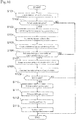
- FIG. 10 is a flowchart illustrating the control procedure of a parking assist process executed by the parking assist device 100 according to the present embodiment.
- the parking assist process is started, which is followed by step S101.
- step S101 detection information from the set of ranging sensors 10, the travel distance sensor 20, and the steering angle sensor 30 is input to the parking assist ECU 50.
- step S102 the vehicle recognition unit 501 executes a process of recognizing the parked vehicles on the basis of the information on the point clouds which is input as clouds of polar coordinates from the set of ranging sensors 10 (see FIG. 3 ).
- step S102 the routine transitions to step S103, while when no parked vehicles 2 are recognized in step S102, the parking assist process is concluded.
- step S103 the vehicle recognition unit 501 calculates the positions and directions of the parked vehicles 2 on the basis of the information on the L-shaped point clouds extracted by clustering and outputs the positions and directions of the parked vehicles 2 to the reference distance calculation unit 503 (see FIG. 4 ).
- step S104 the pathway direction reference line setting unit 502 sets the pathway direction reference line L on the pathway for the subject vehicle 1 and outputs the pathway direction reference line L to the reference distance calculation unit 503 (see FIG. 5 ).
- step S105 the reference distance calculation unit 503 calculates the above reference distances X and the relative positions of the parked vehicles 2 with respect to the pathway direction reference line L and outputs the calculated reference distances X and relative positions of the parked vehicles 2 to the vehicle set division unit 504 (see FIG. 6 ).
- step S106 and step S107 the vehicle set division unit 504 executes a process of grouping two or more parked vehicles 2 into a set of vehicles 3 (see FIG. 7 ).
- step S106 the vehicle set division unit 504 determines whether or not there are two or more parked vehicles 2 that have comparable reference distances X and the same relative positions of the parked vehicles 2 with respect to the pathway direction reference line L.
- the routine transitions to step S107, while when a negative determination is made in step S106, the parking assist process is concluded.
- step S107 the vehicle set division unit 504 groups the two or more parked vehicles 2 that have comparable reference distances X and the same relative positions of the parked vehicles 2 with respect to the pathway direction reference line L into a set of vehicles 3 and outputs information on the set of vehicles 3 and the two or more parked vehicles 2 included in the set of vehicles 3 to the available parking space estimation unit 505.
- step S108 and step S109 the available parking space estimation unit 505 executes the estimation process for an available parking space 5 (see FIG. 8 ).
- the available parking space estimation unit 505 selects one or more sets of vehicles 3 that are closest to the subject vehicle 1 and calculates an inter-vehicle distance W1 of adjacent parked vehicles 2 in the selected one or more sets of vehicles 3.
- step S109 the available parking space estimation unit 505 determines whether or not the calculated inter-vehicle distance W1 and the width W0 of the subject vehicle 1 satisfy the relationship of the above Expression (1).
- the routine transitions to step S110, while when a negative determination is made in step S109, the parking assist process is concluded.
- step S112 the parking route calculation unit 507 calculates a parking route to each available parking subspace 6.
- step S113 the vehicle control unit 508 calculates a vehicle control command value for traveling along the parking route, which is input from the parking route calculation unit 507, and outputs the vehicle control command value to the vehicle control ECU 60.
- the vehicle control ECU 60 executes the drive control for the subject vehicle 1 in accordance with the vehicle control command value which is input from the vehicle control unit 508. The parking assist process is thus completed.
- the parking operation is executed to complete the parking assist process, but the present invention is not limited to this, and the routine may return from step S113 to step S102 to sequentially correct the parking route.
- the available parking space 5 is estimated between the parked vehicles 2.
- the available parking space 5 may be estimated between the parked vehicles 2.
- the position in the longitudinal direction of the subject vehicle 1 parked in the available parking space 5 can be aligned with the positions in the longitudinal direction of other parked vehicles 2, and the subject vehicle 1 parked in the available parking space 5 can be prevented from protruding out of the parking frame.
- the recognition information on the parked vehicles 2 existing in the parking lot is acquired from the set of ranging sensors 10, two or more vehicles parked side by side are extracted from the above recognition information and grouped into a set of vehicles 3, and the available parking space 5 is estimated between the parked vehicles 2 included in the set of vehicles 3.
- This allows the available parking space to be estimated even when a white line representing a parking frame cannot be recognized for some reasons, such as that no white line exists or the white line is unclear.
- the pathway direction reference line L extending along the pathway of the parking lot is set, the reference distances X between the pathway direction reference line L and the parked vehicles 2 included in the recognition information acquired from the set of ranging sensors 10 are calculated, and two or more vehicles are grouped into a set of vehicles 3 on the basis of the reference distances X.
- two or more parked vehicles 2 parked side by side along the pathway of the parking lot can be grouped into a set of vehicles 3.
- the space when a space in which the inter-vehicle distance W1 is larger than the width W0 of one vehicle exists between the parked vehicles 2 included in the grouped set of vehicles 3, the space is estimated as an available parking space 5. This allows at least one vehicle to be parked in the available parking space 5 existing in an area of the grouped set of vehicles 3.
- the available parking space 5 is divided by the integer n in the arrangement direction of the parked vehicles 2 in the set of vehicles 3. This allows at least n vehicles to be parked in the available parking space 5 existing in an area of the grouped set of vehicles 3.
- the parking route to the available parking space 5 is generated and the subject vehicle 1 is controlled to travel along the parking route. This allows execution of the automated parking without requiring the operation by the driver.
- FIG. 11 is a block diagram for describing the functions of a parking assist ECU 150 according to another embodiment of the present invention.
- the parking assist ECU 150 comprises a vehicle recognition unit 501, a vehicle set division unit 151, an available parking space estimation unit 505, an available parking space division unit 506, a parking route calculation unit 507, and a vehicle control unit 508. Description of the same functions as those of the parking assist ECU 50 according to the above embodiment will be omitted, and the description of the above embodiment is borrowed herein.
- FIG. 12 is a plan view for describing a grouping process for a set of vehicles 3.
- the vehicle set division unit 151 groups two or more parked vehicles 2 that have comparable directions (for example, the angle difference is within ⁇ 0-10°) into a set of vehicles 3 and outputs information on the set of vehicles 3 and the two or more parked vehicles 2 included in the set of vehicles 3 to the available parking space estimation unit 505.
- FIG. 13 is a plan view for describing an estimation process for an available parking space 5.
- the available parking space estimation unit 505 selects one or more sets of vehicles 3 that are closest to the subject vehicle 1, from among the two or more sets of vehicles 3. Then, the available parking space estimation unit 505 calculates an inter-vehicle distance W1 of adjacent parked vehicles 2 in the selected one or more sets of vehicles 3.
- the available parking space estimation unit 505 estimates an area in which the inter-vehicle distance W1 satisfies the relationship of Expression (3) as the available parking space 5 and outputs the estimation result to the available parking space division unit 506.
- the available parking space estimation unit 505 estimates the available parking space 5 in a situation in which the inter-vehicle distance W1 and the width W0 of the subject vehicle 1 satisfy the above Expression (1).
- the available parking space estimation unit 505 estimates the available parking space 5 in a situation in which the inter-vehicle distance W1 and the width W0 of the subject vehicle 1 satisfy the above Expression (3).
- the available parking space 5 is set so as to include at least an area onto which one of the parked vehicles 2 located on both sides of the available parking space 5 (for example, a parked vehicle 2 having a longer total length) is projected in the vehicle width direction.
- FIG. 14 is a plan view for describing a division process for the available parking space 5.
- the available parking space division unit 506 calculates whether the width W1 of the estimated available parking space 5 corresponds to n times (n is an integer) the preliminarily set width W2 of a parking frame, as represented by the above Expression (2).
- the available parking space division unit 506 calculates whether the width W1 of the estimated available parking space 5 corresponds to n times (n is an integer) the value W2/cos ⁇ , as represented by the above Expression (4).
- the available parking space division unit 506 divides the available parking space 5 in the width direction (direction parallel to the pathway direction) by the integer n represented by the above Expression (4) and outputs information on the divided available parking space 5 to the parking route calculation unit 507.
- FIG. 15 is a flowchart illustrating the control procedure of a parking assist process according to the present embodiment.
- the parking assist process is started, which is followed by step S101.
- Steps S101 and S102 are executed in the same manner as in the parking assist process of the above-described embodiment.
- the vehicle recognition unit 501 calculates the positions and directions of the parked vehicles 2 on the basis of the information on the L-shaped point clouds extracted by clustering and outputs the positions and directions of the parked vehicles 2 to the vehicle set division unit 151 (see FIG. 4 ).
- step S204 and step S205 the vehicle set division unit 151 executes a process of grouping two or more parked vehicles 2 into a set of vehicles 3 (see FIG. 13 ).
- step S204 the vehicle set division unit 151 determines whether or not there are two or more parked vehicles 2 of which the angle ⁇ between the straight line perpendicular to the longitudinal direction of the parked vehicles 2 and the straight line parallel to the pathway direction is comparable.
- the routine transitions to step S205, while when a negative determination is made in step S204, the parking assist process is concluded.
- step S205 the vehicle set division unit 151 groups the two or more parked vehicles 2 of which the above angle ⁇ is comparable into a set of vehicles 3 and outputs information on the set of vehicles 3 and the two or more parked vehicles 2 included in the set of vehicles 3 to the available parking space estimation unit 505.
- step S206 and step S207 the available parking space estimation unit 505 executes the estimation process for an available parking space 5 (see FIG. 14 ).
- the available parking space estimation unit 505 selects one or more sets of vehicles 3 that are closest to the subject vehicle 1 and calculates an inter-vehicle distance W1 of adjacent parked vehicles 2 of the selected one or more sets of vehicles 3.
- step S207 the available parking space estimation unit 505 determines whether or not the calculated inter-vehicle distance W1 and the width W0 of the subject vehicle 1 satisfy the relationship of the above Expression (3).
- the routine transitions to step S208, while when a negative determination is made in step S207, the parking assist process is concluded.
- steps S112 and S113 are executed in the same manner as in the parking assist process of the above-described embodiment.
- the parking assist process in the present embodiment is thus completed.
- the parking operation is executed to complete the parking assist process, but the present invention is not limited to this, and the routine may return from step S113 to step S102 to sequentially correct the parking route.
- directions of the parked vehicles 2 included in the recognition information from the set of ranging sensors 10 are detected, and two or more vehicles are grouped into a set of vehicles 3 on the basis of the detected directions of the parked vehicles 2.
- two or more parked vehicles 2 parked side by side along the pathway of the parking lot can be grouped into a set of vehicles 3 both in the parking lot of a right-angle parking scheme and in the parking lot of an angle parking scheme.
- FIG. 16 is a block diagram for describing the functions of a parking assist ECU 250 according to another embodiment of the present invention.
- the parking assist ECU 250 comprises a vehicle recognition unit 501, a vehicle set division unit 151, a pathway direction reference line setting unit 502, a reference distance calculation unit 503, a vehicle set division unit 504, an available parking space estimation unit 505, an available parking space division unit 506, a parking route calculation unit 507, and a vehicle control unit 508.
- Description of the same functions as those of the parking assist ECUs 50 and 150 according to the above embodiments will be omitted, and the description of the above embodiments is borrowed herein.
- FIG. 17 is a plan view for describing a grouping process for a set of vehicles 3.
- the vehicle set division unit 151 groups two or more parked vehicles 2 that have comparable directions (for example, the angle difference is within ⁇ 0-10°) into a set of vehicles 3 and outputs information on the set of vehicles 3 and the two or more parked vehicles 2 included in the set of vehicles 3 to the available parking space estimation unit 505.
- parked vehicles 2 having different reference distances X may be mixed.
- FIG. 18 is a plan view for describing a setting process for a pathway direction reference line L and a calculation process for reference distances X.
- the pathway direction reference line setting unit 502 sets the pathway direction reference line L on the pathway for the subject vehicle 1 and outputs the pathway direction reference line L to the reference distance calculation unit 503. Then, the reference distance calculation unit 503 calculates the reference distances X and relative positions of the parked vehicles 2 with respect to the pathway direction reference line L and outputs the calculated reference distances X and relative positions to the vehicle set division unit 504.
- the reference distance calculation unit 503 specifies whether each parked vehicle 2 is located on the right side or left side of the pathway direction reference line L.
- FIG. 19 is a plan view for describing a division process for a set of vehicles 3.
- the vehicle set division unit 504 divides a set of vehicles 3 in which parked vehicles 2 having different reference distances X are mixed, further into two or more sets of vehicles 3A on the basis of the reference distances X. In this case, the reference distances X of the parked vehicles 2 included in each set of vehicles 3A are comparable. Then, the vehicle set division unit 504 outputs information on the two or more sets of vehicles 3A and the parked vehicles 2 included in each set of vehicles 3A to the available parking space estimation unit 505.
- FIG. 20 is a plan view for describing an estimation process for an available parking space 5.
- the available parking space estimation unit 505 selects one or more sets of vehicles 3 that are closest to the subject vehicle 1, from among the two or more sets of vehicles 3. Then, the available parking space estimation unit 505 calculates an inter-vehicle distance W1 of adjacent parked vehicles 2 in the selected one or more sets of vehicles 3.
- the available parking space estimation unit 505 estimates a space in which the inter-vehicle distance W1 satisfies the relationship of Expression (3) as the available parking space 5 and outputs the estimation result to the available parking space division unit 506.
- FIG. 21 is a plan view for describing a division process for the available parking space 5.
- the available parking space division unit 506 calculates whether the width W1 of the estimated available parking space 5 corresponds to n times (n is an integer) the value W2/cos ⁇ , as represented by the above Expression (4). Then, the available parking space division unit 506 divides the available parking space 5 in the width direction (direction parallel to the pathway direction) by the integer n represented by the above Expression (4) and outputs information on the divided available parking space 5 to the parking route calculation unit 507.
- FIG. 22 is a flowchart illustrating the control procedure of a parking assist process according to the present embodiment.
- the parking assist process is started, which is followed by step S101.
- Steps S101, S102, S203, S204, and S205 are executed in the same manner as in the parking assist process of the above-described embodiments.
- step S104 is executed in the same manner as in the parking assist process of the above-described embodiment.
- the pathway direction reference line setting unit 502 sets the pathway direction reference line L on the pathway for the subject vehicle 1 and outputs the pathway direction reference line L to the reference distance calculation unit 503 (see FIG. 18 ).
- the reference distance calculation unit 503 calculates the above reference distances X and the relative positions of the parked vehicles 2 with respect to the pathway direction reference line L and outputs the calculated reference distances X and relative positions to the vehicle set division unit 504.
- step S306 and step S307 the vehicle set division unit 504 executes a process of dividing a set of vehicles 3 (see FIG. 19 ).
- step S306 the vehicle set division unit 504 determines whether or not there is a set of vehicles 3 in which parked vehicles 2 having different reference distances X are mixed.
- step S307 the routine transitions to step S307, while when a negative determination is made in step S306, the routine transitions to step S206.
- step S307 the vehicle set division unit 504 divides the set of vehicles 3 in which parked vehicles 2 having different reference distances X are mixed, further into two or more sets of vehicles 3A on the basis of the reference distances X. Then, the vehicle set division unit 504 outputs information on the sets of vehicles 3 and 3A and the parked vehicles 2 included therein to the available parking space estimation unit 505.
- steps S206, S207, S208, S209, S112, and S113 are executed.
- the parking assist process in the present embodiment is thus completed.
- the parking operation is executed to complete the parking assist process, but the present invention is not limited to this, and the routine may return from step S113 to step S102 to sequentially correct the parking route.
- directions of the parked vehicles 2 included in the recognition information from the set of ranging sensors 10 are detected, and two or more vehicles are grouped into a set of vehicles 3 on the basis of the detected directions of the parked vehicles 2.
- the pathway direction reference line L extending along the pathway of the parking lot is set, the reference distances X between the pathway direction reference line L and the parked vehicles 2 included in the recognition information acquired from the set of ranging sensors 10 are calculated, and the set of vehicles 3 is divided on the basis of the reference distances X.
- the set of vehicles 3 in which parked vehicles 2 having different distances from the pathway are mixed can be divided into two or more sets of vehicles 3A in each of which the distances from the pathway are substantially the same.
- the above embodiments have been described on the assumption that the ranging sensors are equipped in the subject vehicle, but the present invention is not limited to this, and one or more embodiments of the present invention may be carried out on the assumption that a sensor provided at a parking lot, a sensor provided on another vehicle, and/or a camera carried by the user are used.
- information on the set of parking frames may be acquired from external to perceive the parking state in the set of parking frames.
- the space when a space in which the inter-vehicle distance of the parked vehicles 2 is larger than the width of one vehicle exists between the parked vehicles 2 included in the set of vehicles 3, the space is estimated as the available parking space 5. In an alternative embodiment, when a space in which the inter-vehicle distance of the parked vehicles 2 is larger than a predetermined width of a parking frame exists between the parked vehicles 2 included in the set of vehicles 3, the space may be estimated as the available parking space 5.
- the inter-vehicle distance of the parked vehicles 2 located on both sides of the available parking space 5 is larger than a value obtained by multiplying the predetermined width of a parking frame by an integer n larger than one, the available parking space 5 is divided by the integer n in the arrangement direction of the parked vehicles 2 in the set of vehicles 3.
- the available parking space 5 when in the grouped set of vehicles 3 the inter-vehicle distance of the parked vehicles 2 located on both sides of the available parking space 5 is larger than a value obtained by multiplying a predetermined width of a vehicle by an integer n larger than one, the available parking space 5 may be divided by the integer n in the arrangement direction of the parked vehicles 2 in the set of vehicles 3.
Landscapes
- Engineering & Computer Science (AREA)
- Physics & Mathematics (AREA)
- General Physics & Mathematics (AREA)
- Mechanical Engineering (AREA)
- Radar, Positioning & Navigation (AREA)
- Remote Sensing (AREA)
- Transportation (AREA)
- Automation & Control Theory (AREA)
- Theoretical Computer Science (AREA)
- Multimedia (AREA)
- Computer Networks & Wireless Communication (AREA)
- Combustion & Propulsion (AREA)
- Chemical & Material Sciences (AREA)
- Electromagnetism (AREA)
- Mathematical Physics (AREA)
- Human Computer Interaction (AREA)
- Traffic Control Systems (AREA)
Abstract
Description
- The present invention relates to a parking assist method and a parking assist device.
- A parking lot guidance method is known which include performing a white line recognition process on the image data, obtained by an onboard camera imaging a parking area, and recognizing a parking frame on the basis of the recognition result (see Patent Document 1, for example).
- [Patent Document 1]
JP2007-315956A - In the parking lot guidance method as described in Patent Document 1, when a white line representing a parking frame cannot be recognized for some reasons, such as that no white line exists or the white line is unclear, the parking frame cannot be recognized and an available parking space cannot be estimated.
- A problem to be solved by the present invention is to provide a parking assist method and a parking assist device with which an available parking space can be estimated regardless of whether or not a white line representing a parking frame can be recognized.
- The present invention solves the above problem through extracting two or more vehicles parked side by side from recognition information on parked vehicles existing in a parking lot, grouping the two or more vehicles into a set of vehicles, and estimating an available parking space between the parked vehicles included in the set of vehicles.
- According to the present invention, an effect can be obtained that an available parking space can be estimated by using the grouping result of the recognized set of vehicles regardless of whether or not a white line representing a parking frame can be recognized.
-
-
FIG. 1 is a block diagram illustrating the configuration of a parking assist device according to an embodiment of the present invention. -
FIG. 2 is a block diagram for describing functions of a parking assist ECU ofFIG. 1 . -
FIG. 3 is a plan view for describing a recognition process for parked vehicles according to an embodiment of the present invention. -
FIG. 4 is a plan view for describing a calculation process for the positions and directions of parked vehicles according to an embodiment of the present invention. -
FIG. 5 is a plan view for describing a setting process for a pathway direction reference line according to an embodiment of the present invention. -
FIG. 6 is a plan view for describing a calculation process for reference distances according to an embodiment of the present invention. -
FIG. 7 is a plan view for describing a grouping process for a set of vehicles according to an embodiment of the present invention. -
FIG. 8 is a plan view for describing an estimation process for an available parking space according to an embodiment of the present invention. -
FIG. 9 is a plan view for describing a division process for an available parking space according to an embodiment of the present invention. -
FIG. 10 is a flowchart illustrating the control procedure of a parking assist process executed by the parking assist device according to an embodiment of the present invention. -
FIG. 11 is a block diagram for describing functions of a parking assist ECU according to another embodiment of the present invention. -
FIG. 12 is a plan view for describing a grouping process for a set of vehicles according to another embodiment of the present invention. -
FIG. 13 is a plan view for describing an estimation process for an available parking space according to another embodiment of the present invention. -
FIG. 14 is a plan view for describing a division process for an available parking space according to another embodiment of the present invention. -
FIG. 15 is a flowchart illustrating the control procedure of a parking assist process according to another embodiment of the present invention. -
FIG. 16 is a block diagram for describing functions of a parking assist ECU according to another embodiment of the present invention. -
FIG. 17 is a plan view for describing a grouping process for a set of vehicles according to another embodiment of the present invention. -
FIG 18 is plan vie for describing a setting process for a pathway direction reference line and a calculation process for reference distances X according to another embodiment of the present invention. -
FIG. 19 is a plan view for describing a division process for a set of vehicles according to another embodiment of the present invention. -
FIG. 20 is a plan view for describing an estimation process for an available parking space according to another embodiment of the present invention. -
FIG. 21 is a plan view for describing a division process for an available parking space according to another embodiment of the present invention. -
FIG. 22 is a flowchart illustrating the control procedure of a parking assist process according to another embodiment of the present invention. - Hereinafter, one or more embodiments of the present invention will be described with reference to the drawings.
FIG. 1 is a block diagram illustrating the configuration of aparking assist device 100 according to an embodiment of the present invention. Theparking assist device 100 according to the present embodiment, which is equipped in a vehicle, assists an operation of moving (parking) the vehicle into a parking space. Theparking assist device 100 according to the present embodiment comprises a set of rangingsensors 10, atravel distance sensor 20, asteering angle sensor 30, amain switch 40, a parking assist electronic control unit (ECU) 50, and avehicle control ECU 60. Theparking assist device 100 further comprises hardware modules, such as an engine control ECU and a power assist ECU (not illustrated), which are usually equipped in the vehicle. These components are connected to one another via a controller area network (CAN) or other in-vehicle LAN to mutually exchange information. - As illustrated in the figure, the set of ranging
sensors 10 includes, for example, afront ranging sensor 11, a right-side ranging sensor 12, and a left side-rangingsensor 13. Thefront ranging sensor 11, which is provided at or in the vicinity of the front bumper of the vehicle, detects the polar coordinates (distances and orientations) of a cloud of reflection points (seeFIG. 3 ) of an object existing ahead of the subject vehicle and outputs them to theparking assist ECU 50. The right-side ranging sensor 12, which is provided on the right side of the vehicle (e.g. at the front right part of the subject vehicle), detects the polar coordinates of a cloud of reflection points of an object existing on the right side of the subject vehicle and outputs them to the parking assist ECU 50. The left-side ranging sensor 13, which is provided on the left side of the vehicle (e.g. at the front left part of the subject vehicle), detects the polar coordinates of a cloud of reflection points of an object existing on the left side of the subject vehicle and outputs them to the parking assist ECU 50. - Examples of the ranging
sensors 10 include laser scanners, radars, and stereo cameras. Any sensor can be employed as each ranging sensor, provided that it can detect the polar coordinates of a cloud of reflection points of an object. The detection area of the set of rangingsensors 10 is set so as to be able to detect the polar coordinates of clouds of reflection points of two or more parked vehicles that exist on at least the right and left of a pathway for the subject vehicle. - The
travel distance sensor 20 calculates the movement amount of the subject vehicle and outputs it to theparking assist ECU 50. Thetravel distance sensor 20 can be configured, for example, using an appropriate sensor such as a rotation speed sensor that detects the rotation speed of one or more wheels of the subject vehicle. - The
steering angle sensor 30, which is equipped inside the steering column, for example, detects the rotation angle of the steering wheel and outputs it to theparking assist ECU 50. - The
main switch 40, which is a switch for a user to operate to input the start of parking assist, outputs an OFF signal to the parking assist ECU 50 when not operated and outputs an ON signal to the parking assist ECU 50 when operated. Themain switch 40 is disposed, for example, on any position at which the driver can operate it, such as a position around the instrument panel or steering wheel of the subject vehicle. Examples of themain switch 40 also include a software switch presented on the screen of a navigation devise and a software switch presented on the screen of a portable terminal, such as a smartphone, which can communicate with the vehicle via a network. - The parking assist ECU 50 is a controller that comprehensively controls the
parking assist device 100. The parking assist ECU 50 comprises aROM 52 that stores a parking assist program, aCPU 51 as an operation circuit that executes the program stored in theROM 52 to serve as theparking assist device 100 according to the present embodiment, and aRAM 53 that serves as an accessible storage device. Theparking assist ECU 50, to which the detection information is input from the set of rangingsensors 10, thetravel distance sensor 20, thesteering angle sensor 30, and themain switch 40, executes an available parking space estimation process to be described later, then calculates a target vehicle speed and a target steering angle of the subject vehicle, and outputs them to thevehicle control ECU 60. - The vehicle control ECU 60 is a controller that performs drive control of the vehicle. The vehicle control ECU 60 comprises a
ROM 62 that stores a vehicle drive control program, aCPU 61 as an operation circuit that executes the program stored in theROM 62 to serve as a vehicle control device, and aRAM 63 that serves as an accessible storage device. Thevehicle control ECU 60, to which the target vehicle speed and target steering angle of the vehicle are input from the parking assist ECU 50, performs the drive control of the vehicle in cooperation with the engine control ECU, the power assist ECU of the steering, etc. -
FIG. 2 is a block diagram for describing the functions of the parking assist ECU 50. As illustrated in the figure, the parking assist ECU 50 comprises avehicle recognition unit 501, a pathway direction referenceline setting unit 502, a referencedistance calculation unit 503, a vehicleset division unit 504, an available parkingspace estimation unit 505, an available parkingspace division unit 506, a parkingroute calculation unit 507, and avehicle control unit 508. - The
vehicle recognition unit 501 recognizes parked vehicles 2 (seeFIG. 3 , etc.) on the basis of reflection point positional information groups (referred to as "point clouds," hereinafter) that are input as clouds of polar coordinates from the set of rangingsensors 10. Thevehicle recognition unit 501 first performs coordinate conversion on the point clouds, which are input from thefront ranging sensor 11, the right-side ranging sensor 12, and the left side-rangingsensor 13, from the polar coordinates to the xy-plane coordinates for integration and then performs clustering to extract point clouds of close points. -
FIG. 3 is a plan view for describing a recognition process for the parkedvehicles 2. As illustrated in the figure, the parkedvehicles 2 existing in the parking lot are each extracted as an L-shaped point cloud by thevehicle recognition unit 501. The method of recognizing the parkedvehicles 2 is not limited to the above-described method, and other known methods can also be used. -
FIG. 4 is a plan view for describing a calculation process for the positions and directions of the parkedvehicles 2. Thevehicle recognition unit 501 calculates the positions and directions of the parkedvehicles 2 on the basis of the information on the L-shaped point clouds which are extracted by clustering. For example, thevehicle recognition unit 501 calculates a representative point P (seeFIG. 3 ) of each parkedvehicle 2 on the basis of the information on the corresponding L-shaped point cloud and outputs the position of the calculated representative point P and the direction to the referencedistance calculation unit 503 as the position and direction of the parkedvehicle 2. - Here, one of the L-shaped pair of straight lines is a straight line representing the front face of a parked
vehicle 2 parked in the backward direction or the rear face of a parkedvehicle 2 parked in the forward direction while the other straight line is a straight line representing a side surface of the parkedvehicle 2. As illustrated inFIG. 3 , in a situation in which the vector indicating the direction of the subject vehicle 1 and the vector indicating the direction of a parkedvehicle 2 are at a right angle, the front face of a parkedvehicle 2 parked in the backward direction or the rear face of a parkedvehicle 2 parked in the forward direction falls within a range from 45° on the left side to 45° on the right side with respect to the vector indicating the direction of the subject vehicle 1. Thevehicle recognition unit 501 therefore extracts a straight line that falls within the range from 45° on the left side to 45° on the right side with respect to the vector indicating the direction of the subject vehicle 1 as a straight line representing the front face of a parkedvehicle 2 parked in the backward direction or the rear face of a parkedvehicle 2 parked in the forward direction. Then, thevehicle recognition unit 501 calculates the center point of the extracted straight line as the representative point P of the parkedvehicle 2. - The
vehicle recognition unit 501 calculates not only the position of the representative point P of a parkedvehicle 2 but also the direction of the parkedvehicle 2 on the basis of the direction of the straight line representing the front face or rear face of the parkedvehicle 2 and the direction of the straight line representing the side surface of the parkedvehicle 2 and outputs the information on the position of the representative point P of the parkedvehicle 2 and the direction of the parkedvehicle 2 to the referencedistance calculation unit 503. It is not essential to set the representative point P of a parkedvehicle 2 to the center of the front face or rear face of the parkedvehicle 2, and the representative point P may be set to the same position for a plurality of parkedvehicles 2. For example, the representative point P may be set to the right or left end of the front of a parkedvehicle 2 or may also be set to the center (center of gravity) or the like of the parkedvehicle 2. -
FIG. 5 is a plan view for describing a setting process for a pathway direction reference line L. The pathway direction referenceline setting unit 502 sets a pathway direction for the subject vehicle, sets the pathway direction reference line L, which is a straight line along the pathway direction, to the pathway for the subject vehicle 1, and outputs the pathway direction reference line L to the referencedistance calculation unit 503. The pathway direction reference line L is a straight line that passes through an arbitrary point of the subject vehicle 1 (e.g. the above-described center of the front face of the subject vehicle 1). - An exemplary method of setting the pathway direction for the subject vehicle 1 may include making a histogram of a distribution of directions of the parked
vehicles 2 recognized by thevehicle recognition unit 501 and determining a direction of a predetermined angle with respect to the direction which provides a peak among the above directions, as the pathway direction. This method can be applied to a case of preliminarily acquiring information on the angle between the pathway direction for the subject vehicle 1 and the direction of a parking frame. For example, in a case of preliminarily acquiring information indicating that the angle between the pathway direction for the subject vehicle 1 and the direction of a parking frame is 90°, the pathway direction to be set is a direction of 90° with respect to the direction which provides the peak among the directions of the parkedvehicles 2. - Another exemplary method of setting the pathway direction for the subject vehicle 1 may include using a navigation system to acquire map data that includes the parking lot and performing the matching between the map data and the position of the subject vehicle 1 to detect the pathway direction for the subject vehicle 1. In addition or alternatively, information on the pathway direction for the subject vehicle 1 may be acquired through infrastructure systems such as a vehicle-infrastructure cooperative road traffic system and a vehicle-infrastructure cooperative safe driving assist system.
-
FIG. 6 is a plan view for describing a calculation process for reference distances X. The referencedistance calculation unit 503 calculates the reference distances X, which are distances between the positions of the representative points P of the parkedvehicles 2 and the pathway direction reference line L, and relative positions of the parkedvehicles 2 with respect to the pathway direction reference line L and outputs the calculated reference distances X and relative positions to the vehicle setdivision unit 504. When calculating the relative positions of the parkedvehicles 2 with respect to the pathway direction reference line L, the referencedistance calculation unit 503 calculates whether each parkedvehicle 2 is located on the right side or left side of the pathway direction reference line L. -
FIG. 7 is a plan view for describing a grouping process for a set ofvehicles 3. The vehicle setdivision unit 504 groups two or more parkedvehicles 2 that have comparable reference distances X and the same relative positions of the parkedvehicles 2 with respect to the pathway direction reference line L into a set ofvehicles 3 and outputs information on the set ofvehicles 3 and the two or more parkedvehicles 2 included in the set ofvehicles 3 to the available parkingspace estimation unit 505. -
FIG. 8 is a plan view for describing an estimation process for anavailable parking space 5. First, when there are two or more sets ofvehicles 3, the available parkingspace estimation unit 505 selects one or more sets ofvehicles 3 that are closest to the subject vehicle 1, from among the two or more sets ofvehicles 3. As will be understood, when there is only one set ofvehicles 3, the available parkingspace estimation unit 505 consequently selects the one set ofvehicles 3. Then, the available parkingspace estimation unit 505 calculates an inter-vehicle distance W1 of adjacent parkedvehicles 2 in the selected one or more sets ofvehicles 3. - Here, in the case of a right-angle parking scheme as illustrated in
FIG. 8 rather than an angle parking scheme, the inter-vehicle distance W1 and a width W0 of the subject vehicle 1 satisfy the relationship of Expression (1) as below (i.e. a relationship in which the inter-vehicle distance W1 is larger than the width W0 of the subject vehicle 1). Accordingly, when the calculated inter-vehicle distance W1 and the width W0 of the subject vehicle 1 satisfy the relationship of Expression (1), the available parkingspace estimation unit 505 estimates a space in which the inter-vehicle distance W1 satisfies the relationship of Expression (1) as theavailable parking space 5 and outputs the estimation result to the available parkingspace division unit 506. The method of estimating theavailable parking space 5 may be carried out on the basis of the point cloud information acquired by radar or may also be carried out on the basis of the recognition result obtained by a camera.
- The available parking
space estimation unit 505 sets theavailable parking space 5 so that theavailable parking space 5 includes at least an area onto which one of the parkedvehicles 2 located on both sides of the available parking space 5 (for example, a parkedvehicle 2 having a longer total length) is projected in the vehicle width direction. -
FIG. 9 is a plan view for describing a division process for theavailable parking space 5. The available parkingspace division unit 506 calculates whether the width W1 of the estimatedavailable parking space 5 corresponds to n times (n is an integer) a preliminarily set width W2 of a parking frame, as represented by Expression (2) as below. For example, when the width W1 of the estimatedavailable parking space 5 is 6 m and the preliminarily set width W2 of a parking frame is 2.5 m, the width W1 of theavailable parking space 5 corresponds to twice (n=2) the width W2 of the parking frame.
- Then, the available parking
space division unit 506 divides theavailable parking space 5 in the width direction (direction parallel to the pathway direction) by the integer n represented by the above Expression (2) and outputs information on the dividedavailable parking space 5 to the parkingroute calculation unit 507. In the following description, the n available parking spaces included in theavailable parking space 5 are referred to asavailable parking subspaces 6. - When the information on the
available parking space 5 is input from the available parkingspace division unit 506, the parkingroute calculation unit 507 calculates a parking route to eachavailable parking subspace 6. The method of calculating the parking route is not particularly limited, and various known methods can be used. When the navailable parking subspaces 6 include anavailable parking subspace 6 that is set to be unselected by the user of the subject vehicle 1, the parking route to theavailable parking subspace 6 is not calculated. This can reduce the calculation load. - When calculating the parking route, the parking
route calculation unit 507 first sets a parking target position in eachavailable parking subspace 6. In an exemplary method of setting the parking target position, the parking target position may be set to a position at which the center points in the longitudinal direction and width direction of the selectedavailable parking subspace 6 coincide with the center points in the longitudinal direction and width direction of the subject vehicle 1. Then, the parkingroute calculation unit 507 calculates a parking route to the parking target position in eachavailable parking subspace 6. - When calculating the parking route, the parking
route calculation unit 507 may select oneavailable parking subspace 6 from among the navailable parking subspaces 6 included in theavailable parking space 5 and calculate the parking route to the selectedavailable parking subspace 6. In an exemplary method of selecting oneavailable parking subspace 6 from among the navailable parking subspaces 6, anavailable parking subspace 6 closest to the subject vehicle 1 may be selected. - The
vehicle control unit 508 calculates a vehicle control command value for traveling along the parking route input from the parkingroute calculation unit 507 and outputs the vehicle control command value to thevehicle control ECU 60. Examples of the vehicle control command value include the target vehicle speed and the target steering angle, for example, but other command values such as the acceleration of the subject vehicle may be included in the vehicle control command value. The method of calculating the vehicle control command value is not particularly limited, and various known methods can be used. -
FIG. 10 is a flowchart illustrating the control procedure of a parking assist process executed by the parking assistdevice 100 according to the present embodiment. In the present embodiment, when an ON signal is input from themain switch 40 to the parking assistECU 50, the parking assist process is started, which is followed by step S101. - In step S101, detection information from the set of ranging
sensors 10, thetravel distance sensor 20, and thesteering angle sensor 30 is input to the parking assistECU 50. Then, in step S102, thevehicle recognition unit 501 executes a process of recognizing the parked vehicles on the basis of the information on the point clouds which is input as clouds of polar coordinates from the set of ranging sensors 10 (seeFIG. 3 ). When the parkedvehicles 2 are recognized in step S102, the routine transitions to step S103, while when no parkedvehicles 2 are recognized in step S102, the parking assist process is concluded. - In step S103, the
vehicle recognition unit 501 calculates the positions and directions of the parkedvehicles 2 on the basis of the information on the L-shaped point clouds extracted by clustering and outputs the positions and directions of the parkedvehicles 2 to the reference distance calculation unit 503 (seeFIG. 4 ). Then, in step S104, the pathway direction referenceline setting unit 502 sets the pathway direction reference line L on the pathway for the subject vehicle 1 and outputs the pathway direction reference line L to the reference distance calculation unit 503 (seeFIG. 5 ). Then, in step S105, the referencedistance calculation unit 503 calculates the above reference distances X and the relative positions of the parkedvehicles 2 with respect to the pathway direction reference line L and outputs the calculated reference distances X and relative positions of the parkedvehicles 2 to the vehicle set division unit 504 (seeFIG. 6 ). - Then, in step S106 and step S107, the vehicle set
division unit 504 executes a process of grouping two or more parkedvehicles 2 into a set of vehicles 3 (seeFIG. 7 ). First, in step S106, the vehicle setdivision unit 504 determines whether or not there are two or more parkedvehicles 2 that have comparable reference distances X and the same relative positions of the parkedvehicles 2 with respect to the pathway direction reference line L. When an affirmative determination is made in step S106, the routine transitions to step S107, while when a negative determination is made in step S106, the parking assist process is concluded. In step S107, the vehicle setdivision unit 504 groups the two or more parkedvehicles 2 that have comparable reference distances X and the same relative positions of the parkedvehicles 2 with respect to the pathway direction reference line L into a set ofvehicles 3 and outputs information on the set ofvehicles 3 and the two or more parkedvehicles 2 included in the set ofvehicles 3 to the available parkingspace estimation unit 505. - Then, in step S108 and step S109, the available parking
space estimation unit 505 executes the estimation process for an available parking space 5 (seeFIG. 8 ). First, in step S108, the available parkingspace estimation unit 505 selects one or more sets ofvehicles 3 that are closest to the subject vehicle 1 and calculates an inter-vehicle distance W1 of adjacent parkedvehicles 2 in the selected one or more sets ofvehicles 3. Then, in step S109, the available parkingspace estimation unit 505 determines whether or not the calculated inter-vehicle distance W1 and the width W0 of the subject vehicle 1 satisfy the relationship of the above Expression (1). When an affirmative determination is made in step S109, the routine transitions to step S110, while when a negative determination is made in step S109, the parking assist process is concluded. - In step S110, the available parking
space estimation unit 505 estimates an area in which the inter-vehicle distance W1 and the width W0 of the subject vehicle 1 satisfy the relationship of the above Expression (1) as theavailable parking space 5 and outputs the estimation result to the available parkingspace division unit 506. Then, in step Sill, the available parkingspace division unit 506 divides theavailable parking space 5 in the width direction by the integer n represented by the above Expression (2) and outputs information on the dividedavailable parking space 5 to the parking route calculation unit 507 (seeFIG. 9 ). In the case of n=1, division of theavailable parking space 5 is consequently not executed. - Then, in step S112, the parking
route calculation unit 507 calculates a parking route to eachavailable parking subspace 6. Then, in step S113, thevehicle control unit 508 calculates a vehicle control command value for traveling along the parking route, which is input from the parkingroute calculation unit 507, and outputs the vehicle control command value to thevehicle control ECU 60. Thevehicle control ECU 60 executes the drive control for the subject vehicle 1 in accordance with the vehicle control command value which is input from thevehicle control unit 508. The parking assist process is thus completed. - In the above-described control procedure of the parking assist process, after the parking route to the
available parking subspace 6 is calculated, the parking operation is executed to complete the parking assist process, but the present invention is not limited to this, and the routine may return from step S113 to step S102 to sequentially correct the parking route. - In the above-described control procedure of the parking assist process, when the inter-vehicle distance W1 of the parked
vehicles 2 in the grouped set ofvehicles 3 is larger than the width W0 of one vehicle, theavailable parking space 5 is estimated between the parkedvehicles 2. In an alternative embodiment, when the inter-vehicle distance W1 of the parkedvehicles 2 in the set ofvehicles 3 is larger than the width W0 of one vehicle and a space having a longitudinal length longer than the length of one vehicle exists between the parkedvehicles 2 in the set ofvehicles 3, theavailable parking space 5 may be estimated between the parkedvehicles 2. In this case, the position in the longitudinal direction of the subject vehicle 1 parked in theavailable parking space 5 can be aligned with the positions in the longitudinal direction of other parkedvehicles 2, and the subject vehicle 1 parked in theavailable parking space 5 can be prevented from protruding out of the parking frame. - As described above, in the parking assist method and parking assist
device 100 according to the present embodiment, the recognition information on the parkedvehicles 2 existing in the parking lot is acquired from the set of rangingsensors 10, two or more vehicles parked side by side are extracted from the above recognition information and grouped into a set ofvehicles 3, and theavailable parking space 5 is estimated between the parkedvehicles 2 included in the set ofvehicles 3. This allows the available parking space to be estimated even when a white line representing a parking frame cannot be recognized for some reasons, such as that no white line exists or the white line is unclear. - In the parking assist method and parking assist
device 100 according to the present embodiment, the pathway direction reference line L extending along the pathway of the parking lot is set, the reference distances X between the pathway direction reference line L and the parkedvehicles 2 included in the recognition information acquired from the set of rangingsensors 10 are calculated, and two or more vehicles are grouped into a set ofvehicles 3 on the basis of the reference distances X. Through this operation, two or more parkedvehicles 2 parked side by side along the pathway of the parking lot can be grouped into a set ofvehicles 3. - In the parking assist method and parking assist
device 100 according to the present embodiment, when a space in which the inter-vehicle distance W1 is larger than the width W0 of one vehicle exists between the parkedvehicles 2 included in the grouped set ofvehicles 3, the space is estimated as anavailable parking space 5. This allows at least one vehicle to be parked in theavailable parking space 5 existing in an area of the grouped set ofvehicles 3. - In the parking assist method and parking assist
device 100 according to the present embodiment, when the inter-vehicle distance W1 of the parkedvehicles 2 located on both sides of theavailable parking space 5 is larger than a value obtained by multiplying the predetermined width W2 of a parking frame by an integer n larger than one, theavailable parking space 5 is divided by the integer n in the arrangement direction of the parkedvehicles 2 in the set ofvehicles 3. This allows at least n vehicles to be parked in theavailable parking space 5 existing in an area of the grouped set ofvehicles 3. - In the parking assist method and parking assist
device 100 according to the present embodiment, the parking route to theavailable parking space 5 is generated and the subject vehicle 1 is controlled to travel along the parking route. This allows execution of the automated parking without requiring the operation by the driver. -
FIG. 11 is a block diagram for describing the functions of a parking assistECU 150 according to another embodiment of the present invention. As illustrated in the figure, the parking assistECU 150 comprises avehicle recognition unit 501, a vehicle setdivision unit 151, an available parkingspace estimation unit 505, an available parkingspace division unit 506, a parkingroute calculation unit 507, and avehicle control unit 508. Description of the same functions as those of the parking assistECU 50 according to the above embodiment will be omitted, and the description of the above embodiment is borrowed herein. -
FIG. 12 is a plan view for describing a grouping process for a set ofvehicles 3. The vehicle setdivision unit 151 groups two or more parkedvehicles 2 that have comparable directions (for example, the angle difference is within ±0-10°) into a set ofvehicles 3 and outputs information on the set ofvehicles 3 and the two or more parkedvehicles 2 included in the set ofvehicles 3 to the available parkingspace estimation unit 505. -
FIG. 13 is a plan view for describing an estimation process for anavailable parking space 5. First, when there are two or more sets ofvehicles 3, the available parkingspace estimation unit 505 selects one or more sets ofvehicles 3 that are closest to the subject vehicle 1, from among the two or more sets ofvehicles 3. Then, the available parkingspace estimation unit 505 calculates an inter-vehicle distance W1 of adjacent parkedvehicles 2 in the selected one or more sets ofvehicles 3. - Then, when the calculated inter-vehicle distance W1 and the width W0 of the subject vehicle 1 satisfy the relationship of Expression (3) as below, the available parking
space estimation unit 505 estimates an area in which the inter-vehicle distance W1 satisfies the relationship of Expression (3) as theavailable parking space 5 and outputs the estimation result to the available parkingspace division unit 506.
vehicles 2 and a straight line parallel to the pathway direction. - Here, in the case of a right-angle parking scheme as illustrated in
FIG. 8 rather than an angle parking scheme, the angle α between the straight line perpendicular to the longitudinal direction of the parkedvehicles 2 and the straight line parallel to the pathway direction is 0° because the width direction of a parking frame and the arrangement direction of the parking frames are parallel to each other. In such a case, therefore, the available parkingspace estimation unit 505 estimates theavailable parking space 5 in a situation in which the inter-vehicle distance W1 and the width W0 of the subject vehicle 1 satisfy the above Expression (1). - On the other hand, in the case of an angle parking scheme as illustrated in
FIG. 13 , the angle between the width direction of a parking frame and the arrangement direction of the parking frames is a certain angle α (0°<α<90°). In such a case, therefore, the available parkingspace estimation unit 505 estimates theavailable parking space 5 in a situation in which the inter-vehicle distance W1 and the width W0 of the subject vehicle 1 satisfy the above Expression (3). - The
available parking space 5 is set so as to include at least an area onto which one of the parkedvehicles 2 located on both sides of the available parking space 5 (for example, a parkedvehicle 2 having a longer total length) is projected in the vehicle width direction. -
FIG. 14 is a plan view for describing a division process for theavailable parking space 5. The available parkingspace division unit 506 calculates whether the width W1 of the estimatedavailable parking space 5 corresponds to n times (n is an integer) the value W2/cos α, as represented by Expression (4) as below:
vehicles 2 and a straight line parallel to the pathway direction, and W2 represents a preliminarily set width of a parking frame. - In the case of a right-angle parking scheme as illustrated in
FIG. 9 rather than an angle parking scheme, the angle α between the straight line perpendicular to the longitudinal direction of the parkedvehicles 2 and the straight line parallel to the pathway direction is 0° because the width direction of a parking frame and the arrangement direction of the parking frames are parallel to each other. In such a case, therefore, the available parkingspace division unit 506 calculates whether the width W1 of the estimatedavailable parking space 5 corresponds to n times (n is an integer) the preliminarily set width W2 of a parking frame, as represented by the above Expression (2). - On the other hand, in the case of an angle parking scheme as illustrated in
FIG. 14 , the angle between the width direction of a parking frame and the arrangement direction of the parking frames is a certain angle α (0°<α<90°). In such a case, therefore, the available parkingspace division unit 506 calculates whether the width W1 of the estimatedavailable parking space 5 corresponds to n times (n is an integer) the value W2/cos α, as represented by the above Expression (4). - Then, the available parking
space division unit 506 divides theavailable parking space 5 in the width direction (direction parallel to the pathway direction) by the integer n represented by the above Expression (4) and outputs information on the dividedavailable parking space 5 to the parkingroute calculation unit 507. -
FIG. 15 is a flowchart illustrating the control procedure of a parking assist process according to the present embodiment. In the present embodiment, when an ON signal is input from themain switch 40 to the parking assistECU 150, the parking assist process is started, which is followed by step S101. - Steps S101 and S102 are executed in the same manner as in the parking assist process of the above-described embodiment. Then, in step S203, the
vehicle recognition unit 501 calculates the positions and directions of the parkedvehicles 2 on the basis of the information on the L-shaped point clouds extracted by clustering and outputs the positions and directions of the parkedvehicles 2 to the vehicle set division unit 151 (seeFIG. 4 ). - Then, in step S204 and step S205, the vehicle set
division unit 151 executes a process of grouping two or more parkedvehicles 2 into a set of vehicles 3 (seeFIG. 13 ). First, in step S204, the vehicle setdivision unit 151 determines whether or not there are two or more parkedvehicles 2 of which the angle α between the straight line perpendicular to the longitudinal direction of the parkedvehicles 2 and the straight line parallel to the pathway direction is comparable. When an affirmative determination is made in step S204, the routine transitions to step S205, while when a negative determination is made in step S204, the parking assist process is concluded. In step S205, the vehicle setdivision unit 151 groups the two or more parkedvehicles 2 of which the above angle α is comparable into a set ofvehicles 3 and outputs information on the set ofvehicles 3 and the two or more parkedvehicles 2 included in the set ofvehicles 3 to the available parkingspace estimation unit 505. - Then, in step S206 and step S207, the available parking
space estimation unit 505 executes the estimation process for an available parking space 5 (seeFIG. 14 ). First, in step S206, the available parkingspace estimation unit 505 selects one or more sets ofvehicles 3 that are closest to the subject vehicle 1 and calculates an inter-vehicle distance W1 of adjacent parkedvehicles 2 of the selected one or more sets ofvehicles 3. Then, in step S207, the available parkingspace estimation unit 505 determines whether or not the calculated inter-vehicle distance W1 and the width W0 of the subject vehicle 1 satisfy the relationship of the above Expression (3). When an affirmative determination is made in step S207, the routine transitions to step S208, while when a negative determination is made in step S207, the parking assist process is concluded. - In step S208, the available parking
space estimation unit 505 estimates a space in which the inter-vehicle distance W1 and the width W0 of the subject vehicle 1 satisfy the relationship of the above Expression (3) as theavailable parking space 5 and outputs the estimation result to the available parkingspace division unit 506. Then, in step S209, the available parkingspace division unit 506 divides theavailable parking space 5 in the width direction by the integer n represented by the above Expression (4) and outputs information on the dividedavailable parking space 5 to the parking route calculation unit 507 (seeFIG. 14 ). In the case of n=1, division of theavailable parking space 5 is consequently not executed. - Then, steps S112 and S113 are executed in the same manner as in the parking assist process of the above-described embodiment. The parking assist process in the present embodiment is thus completed.
- In the above-described control procedure of the parking assist process, after the parking route to the
available parking subspace 6 is calculated, the parking operation is executed to complete the parking assist process, but the present invention is not limited to this, and the routine may return from step S113 to step S102 to sequentially correct the parking route. - As described above, in the parking assist method and parking assist device according to the present embodiment, directions of the parked
vehicles 2 included in the recognition information from the set of rangingsensors 10 are detected, and two or more vehicles are grouped into a set ofvehicles 3 on the basis of the detected directions of the parkedvehicles 2. Through this operation, two or more parkedvehicles 2 parked side by side along the pathway of the parking lot can be grouped into a set ofvehicles 3 both in the parking lot of a right-angle parking scheme and in the parking lot of an angle parking scheme. -
FIG. 16 is a block diagram for describing the functions of a parking assistECU 250 according to another embodiment of the present invention. As illustrated in the figure, the parking assistECU 250 comprises avehicle recognition unit 501, a vehicle setdivision unit 151, a pathway direction referenceline setting unit 502, a referencedistance calculation unit 503, a vehicle setdivision unit 504, an available parkingspace estimation unit 505, an available parkingspace division unit 506, a parkingroute calculation unit 507, and avehicle control unit 508. Description of the same functions as those of the parking assistECUs -
FIG. 17 is a plan view for describing a grouping process for a set ofvehicles 3. As illustrated in the figure, the vehicle setdivision unit 151 groups two or more parkedvehicles 2 that have comparable directions (for example, the angle difference is within ±0-10°) into a set ofvehicles 3 and outputs information on the set ofvehicles 3 and the two or more parkedvehicles 2 included in the set ofvehicles 3 to the available parkingspace estimation unit 505. Here, as illustrated inFIG. 18 , parkedvehicles 2 having different reference distances X may be mixed. -
FIG. 18 is a plan view for describing a setting process for a pathway direction reference line L and a calculation process for reference distances X. The pathway direction referenceline setting unit 502 sets the pathway direction reference line L on the pathway for the subject vehicle 1 and outputs the pathway direction reference line L to the referencedistance calculation unit 503. Then, the referencedistance calculation unit 503 calculates the reference distances X and relative positions of the parkedvehicles 2 with respect to the pathway direction reference line L and outputs the calculated reference distances X and relative positions to the vehicle setdivision unit 504. When calculating the relative positions of the parkedvehicles 2 with respect to the pathway direction reference line L, the referencedistance calculation unit 503 specifies whether each parkedvehicle 2 is located on the right side or left side of the pathway direction reference line L. -
FIG. 19 is a plan view for describing a division process for a set ofvehicles 3. The vehicle setdivision unit 504 divides a set ofvehicles 3 in which parkedvehicles 2 having different reference distances X are mixed, further into two or more sets ofvehicles 3A on the basis of the reference distances X. In this case, the reference distances X of the parkedvehicles 2 included in each set ofvehicles 3A are comparable. Then, the vehicle setdivision unit 504 outputs information on the two or more sets ofvehicles 3A and the parkedvehicles 2 included in each set ofvehicles 3A to the available parkingspace estimation unit 505. -
FIG. 20 is a plan view for describing an estimation process for anavailable parking space 5. First, when there are two or more sets ofvehicles 3, the available parkingspace estimation unit 505 selects one or more sets ofvehicles 3 that are closest to the subject vehicle 1, from among the two or more sets ofvehicles 3. Then, the available parkingspace estimation unit 505 calculates an inter-vehicle distance W1 of adjacent parkedvehicles 2 in the selected one or more sets ofvehicles 3. Then, when the calculated inter-vehicle distance W1 and the width W0 of the subject vehicle 1 satisfy the relationship of the above Expression (3), the available parkingspace estimation unit 505 estimates a space in which the inter-vehicle distance W1 satisfies the relationship of Expression (3) as theavailable parking space 5 and outputs the estimation result to the available parkingspace division unit 506. -
FIG. 21 is a plan view for describing a division process for theavailable parking space 5. The available parkingspace division unit 506 calculates whether the width W1 of the estimatedavailable parking space 5 corresponds to n times (n is an integer) the value W2/cos α, as represented by the above Expression (4). Then, the available parkingspace division unit 506 divides theavailable parking space 5 in the width direction (direction parallel to the pathway direction) by the integer n represented by the above Expression (4) and outputs information on the dividedavailable parking space 5 to the parkingroute calculation unit 507. -
FIG. 22 is a flowchart illustrating the control procedure of a parking assist process according to the present embodiment. In the present embodiment, when an ON signal is input from themain switch 40 to the parking assistECU 250, the parking assist process is started, which is followed by step S101. - Steps S101, S102, S203, S204, and S205 are executed in the same manner as in the parking assist process of the above-described embodiments. Then, step S104 is executed in the same manner as in the parking assist process of the above-described embodiment. In this step, the pathway direction reference
line setting unit 502 sets the pathway direction reference line L on the pathway for the subject vehicle 1 and outputs the pathway direction reference line L to the reference distance calculation unit 503 (seeFIG. 18 ). Then, in step S305, the referencedistance calculation unit 503 calculates the above reference distances X and the relative positions of the parkedvehicles 2 with respect to the pathway direction reference line L and outputs the calculated reference distances X and relative positions to the vehicle setdivision unit 504. - Then, in step S306 and step S307, the vehicle set
division unit 504 executes a process of dividing a set of vehicles 3 (seeFIG. 19 ). First, in step S306, the vehicle setdivision unit 504 determines whether or not there is a set ofvehicles 3 in which parkedvehicles 2 having different reference distances X are mixed. When an affirmative determination is made in step S306, the routine transitions to step S307, while when a negative determination is made in step S306, the routine transitions to step S206. - In step S307, the vehicle set
division unit 504 divides the set ofvehicles 3 in which parkedvehicles 2 having different reference distances X are mixed, further into two or more sets ofvehicles 3A on the basis of the reference distances X. Then, the vehicle setdivision unit 504 outputs information on the sets ofvehicles vehicles 2 included therein to the available parkingspace estimation unit 505. - Then, steps S206, S207, S208, S209, S112, and S113 are executed. The parking assist process in the present embodiment is thus completed.
- In the above-described control procedure of the parking assist process, after the parking route to the
available parking subspace 6 is calculated, the parking operation is executed to complete the parking assist process, but the present invention is not limited to this, and the routine may return from step S113 to step S102 to sequentially correct the parking route. - As described above, in the parking assist method and parking assist device according to the present embodiment, directions of the parked
vehicles 2 included in the recognition information from the set of rangingsensors 10 are detected, and two or more vehicles are grouped into a set ofvehicles 3 on the basis of the detected directions of the parkedvehicles 2. Moreover, the pathway direction reference line L extending along the pathway of the parking lot is set, the reference distances X between the pathway direction reference line L and the parkedvehicles 2 included in the recognition information acquired from the set of rangingsensors 10 are calculated, and the set ofvehicles 3 is divided on the basis of the reference distances X. Through this operation, both in the parking lot of a right-angle parking scheme and in the parking lot of an angle parking scheme, the set ofvehicles 3 in which parkedvehicles 2 having different distances from the pathway are mixed can be divided into two or more sets ofvehicles 3A in each of which the distances from the pathway are substantially the same. - Embodiments heretofore explained are described to facilitate understanding of the present invention and are not described to limit the present invention. It is therefore intended that the elements disclosed in the above embodiments include all design changes and equivalents to fall within the technical scope of the present invention.
- For example, the above embodiments have been described on the assumption that the ranging sensors are equipped in the subject vehicle, but the present invention is not limited to this, and one or more embodiments of the present invention may be carried out on the assumption that a sensor provided at a parking lot, a sensor provided on another vehicle, and/or a camera carried by the user are used. In such cases, information on the set of parking frames may be acquired from external to perceive the parking state in the set of parking frames.
- In the above-described embodiments, when a space in which the inter-vehicle distance of the parked
vehicles 2 is larger than the width of one vehicle exists between the parkedvehicles 2 included in the set ofvehicles 3, the space is estimated as theavailable parking space 5. In an alternative embodiment, when a space in which the inter-vehicle distance of the parkedvehicles 2 is larger than a predetermined width of a parking frame exists between the parkedvehicles 2 included in the set ofvehicles 3, the space may be estimated as theavailable parking space 5. - In the above-described embodiments, when in the grouped set of
vehicles 3 the inter-vehicle distance of the parkedvehicles 2 located on both sides of theavailable parking space 5 is larger than a value obtained by multiplying the predetermined width of a parking frame by an integer n larger than one, theavailable parking space 5 is divided by the integer n in the arrangement direction of the parkedvehicles 2 in the set ofvehicles 3. In an alternative embodiment, when in the grouped set ofvehicles 3 the inter-vehicle distance of the parkedvehicles 2 located on both sides of theavailable parking space 5 is larger than a value obtained by multiplying a predetermined width of a vehicle by an integer n larger than one, theavailable parking space 5 may be divided by the integer n in the arrangement direction of the parkedvehicles 2 in the set ofvehicles 3. -
- 1
- Subject vehicle
- 2
- Parked vehicle
- 3
- Set of vehicles
- 5
- Available parking space
- 6
- Available parking subspace
- 50
- Parking assist ECU
- 60
- Vehicle control ECU
- 100
- Parking assist device
- L
- Pathway direction reference line
- X
- Reference distance
Claims (8)
- A parking assist method comprising:acquiring recognition information on parked vehicles existing in a parking lot;extracting two or more vehicles parked side by side from the recognition information and grouping the two or more vehicles into a set of vehicles; andwhen a space into which parking is possible exists between the parked vehicles included in the grouped set of vehicles, estimating the space as an available parking space.
- The parking assist method according to claim 1, comprising
setting a reference line extending along a pathway of the parking lot;
calculating distances between the reference line and the parked vehicles included in the recognition information; and
extracting the two or more vehicles from the recognition information and grouping the two or more vehicles into the set of vehicles on a basis of the calculated distances. - The parking assist method according to claim 1 or 2, comprising
detecting directions of the parked vehicles included in the recognition information; and
extracting the two or more vehicles from the recognition information and grouping the two or more vehicles into the set of vehicles on a basis of the detected directions. - The parking assist method according to any one of claims 1 to 3, wherein when the space in which an inter-vehicle distance of the parked vehicles is larger than a width of one vehicle or a predetermined width of a parking frame exists between the parked vehicles included in the set of vehicles, the space is estimated as the available parking space.
- The parking assist method according to claim 4, wherein when the space in which a length in a longitudinal direction of the parked vehicles is larger than a length of one vehicle exists between the parked vehicles included in the set of vehicles, the space is estimated as the available parking space.
- The parking assist method according to claim 4 or 5, wherein when the inter-vehicle distance of the parked vehicles located on both sides of the available parking space is larger than a value obtained by multiplying the predetermined width of the parking frame or the width of the one vehicle by an integer n larger than one, the available parking space is divided by the integer n in an arrangement direction of the parked vehicles in the set of vehicles.
- The parking assist method according to any one of claims 1 to 6, comprising
generating a parking route to the available parking space; and
controlling a subject vehicle to travel along the parking route. - A parking assist device comprising a parking assist controller having a parking assist function, the parking assist controller being configured to:acquire recognition information on parked vehicles existing in a parking lot;extract two or more vehicles parked side by side from the recognition information and group the two or more vehicles into a set of vehicles; andwhen a space into which parking is possible exists between the parked vehicles included in the grouped set of vehicles, estimate the space as an available parking space.
Applications Claiming Priority (1)
| Application Number | Priority Date | Filing Date | Title |
|---|---|---|---|
| PCT/JP2016/063331 WO2017187592A1 (en) | 2016-04-28 | 2016-04-28 | Method and device for parking assistance |
Publications (3)
| Publication Number | Publication Date |
|---|---|
| EP3451311A1 true EP3451311A1 (en) | 2019-03-06 |
| EP3451311A4 EP3451311A4 (en) | 2019-05-15 |
| EP3451311B1 EP3451311B1 (en) | 2021-06-16 |
Family
ID=60160341
Family Applications (1)
| Application Number | Title | Priority Date | Filing Date |
|---|---|---|---|
| EP16900462.9A Active EP3451311B1 (en) | 2016-04-28 | 2016-04-28 | Method and device for parking assistance |
Country Status (9)
| Country | Link |
|---|---|
| US (1) | US10733889B2 (en) |
| EP (1) | EP3451311B1 (en) |
| JP (1) | JP6665929B2 (en) |
| KR (1) | KR102076439B1 (en) |
| CN (1) | CN109074743A (en) |
| BR (1) | BR112018072028A2 (en) |
| CA (1) | CA3022346A1 (en) |
| RU (1) | RU2707409C1 (en) |
| WO (1) | WO2017187592A1 (en) |
Families Citing this family (10)
| Publication number | Priority date | Publication date | Assignee | Title |
|---|---|---|---|---|
| KR102264395B1 (en) * | 2014-08-18 | 2021-06-14 | 현대모비스 주식회사 | Apparatus and method for guiding parking zone |
| DE102017204271A1 (en) * | 2017-03-15 | 2018-09-20 | Bayerische Motoren Werke Aktiengesellschaft | Optimal climate conditioning when parking |
| DE102017208385A1 (en) * | 2017-05-18 | 2018-11-22 | Ford Global Technologies, Llc | A method for supporting a parking operation of a motor vehicle, electronic parking assistance system and motor vehicle |
| US10967851B2 (en) * | 2018-09-24 | 2021-04-06 | Ford Global Technologies, Llc | Vehicle system and method for setting variable virtual boundary |
| JP7229804B2 (en) * | 2019-02-14 | 2023-02-28 | フォルシアクラリオン・エレクトロニクス株式会社 | Image processing device and image processing method |
| DE102019209482B3 (en) * | 2019-06-28 | 2020-08-27 | Volkswagen Aktiengesellschaft | Method for recognizing a parking space that is becoming vacant by an assistance system with a radar sensor, as well as assistance system and motor vehicle |
| CN113670305A (en) * | 2020-05-13 | 2021-11-19 | 长沙智能驾驶研究院有限公司 | Parking trajectory generation method and device, computer equipment and storage medium |
| CN112435500B (en) * | 2020-12-01 | 2022-03-08 | 深圳市顺易通信息科技有限公司 | Method and device for counting remaining parking spaces of parking lot and terminal equipment |
| WO2023171401A1 (en) * | 2022-03-11 | 2023-09-14 | ソニーセミコンダクタソリューションズ株式会社 | Signal processing device, signal processing method, and recording medium |
| US20230311854A1 (en) * | 2022-03-29 | 2023-10-05 | Continental Autonomous Mobility US, LLC | Autonomous vehicle garage parking |
Family Cites Families (19)
| Publication number | Priority date | Publication date | Assignee | Title |
|---|---|---|---|---|
| KR100908421B1 (en) | 2004-08-19 | 2009-07-21 | 아이신세이끼가부시끼가이샤 | Car parking assistance device and method |
| KR100894530B1 (en) | 2004-08-19 | 2009-04-24 | 아이신세이끼가부시끼가이샤 | Parking assist apparatus and parking assist method for vehicle |
| JP4543983B2 (en) * | 2005-03-22 | 2010-09-15 | 株式会社豊田自動織機 | Parking assistance device |
| JP4432930B2 (en) * | 2006-04-25 | 2010-03-17 | トヨタ自動車株式会社 | Parking assistance device and parking assistance method |
| JP2007315956A (en) | 2006-05-26 | 2007-12-06 | Aisin Aw Co Ltd | Map creation method, guiding method and navigation device for parking lot |
| JP2009096306A (en) * | 2007-10-16 | 2009-05-07 | Hiroshima Industrial Promotion Organization | Parking assist method |
| JP4706711B2 (en) | 2008-03-25 | 2011-06-22 | パナソニック電工株式会社 | Parking space monitoring device |
| JP2010012908A (en) * | 2008-07-03 | 2010-01-21 | Nikon Corp | Parking assist range finding system |
| KR101465905B1 (en) * | 2010-06-11 | 2014-11-26 | 닛산 지도우샤 가부시키가이샤 | Parking assistance device and method |
| JP2013116698A (en) * | 2011-12-05 | 2013-06-13 | Denso Corp | Control system |
| KR20140144470A (en) * | 2013-06-11 | 2014-12-19 | 주식회사 만도 | Parking control method, device and system |
| DE102014111011A1 (en) | 2014-08-04 | 2016-02-04 | Valeo Schalter Und Sensoren Gmbh | Method for determining a parking area for parking a motor vehicle, driver assistance system and motor vehicle |
| JP6067635B2 (en) | 2014-09-12 | 2017-01-25 | アイシン精機株式会社 | Parking assistance device |
| JP6517561B2 (en) * | 2015-03-27 | 2019-05-22 | クラリオン株式会社 | Vehicle control device |
| US10703360B2 (en) | 2015-12-17 | 2020-07-07 | Nissan Motor Co., Ltd. | Parking support method and device |
| MX2018007134A (en) | 2015-12-17 | 2018-08-15 | Nissan Motor | Parking support method and device. |
| US20170186317A1 (en) * | 2015-12-29 | 2017-06-29 | Tannery Creek Systems Inc. | System and Method for Determining Parking Infraction |
| JP6656359B2 (en) | 2016-04-15 | 2020-03-04 | 三菱電機株式会社 | Parking assist display control device and parking assist display control method |
| US10852153B2 (en) * | 2017-05-12 | 2020-12-01 | Lg Electronics Inc. | Autonomous vehicle and method of controlling the same |
-
2016
- 2016-04-28 RU RU2018139286A patent/RU2707409C1/en active
- 2016-04-28 WO PCT/JP2016/063331 patent/WO2017187592A1/en active Application Filing
- 2016-04-28 JP JP2018514047A patent/JP6665929B2/en active Active
- 2016-04-28 KR KR1020187030851A patent/KR102076439B1/en active IP Right Grant
- 2016-04-28 BR BR112018072028-3A patent/BR112018072028A2/en not_active Application Discontinuation
- 2016-04-28 CN CN201680084963.1A patent/CN109074743A/en active Pending
- 2016-04-28 CA CA3022346A patent/CA3022346A1/en not_active Abandoned
- 2016-04-28 EP EP16900462.9A patent/EP3451311B1/en active Active
- 2016-04-28 US US16/096,445 patent/US10733889B2/en active Active
Also Published As
| Publication number | Publication date |
|---|---|
| KR102076439B1 (en) | 2020-02-11 |
| WO2017187592A1 (en) | 2017-11-02 |
| CA3022346A1 (en) | 2017-11-02 |
| JPWO2017187592A1 (en) | 2019-03-14 |
| EP3451311B1 (en) | 2021-06-16 |
| CN109074743A (en) | 2018-12-21 |
| KR20180128030A (en) | 2018-11-30 |
| JP6665929B2 (en) | 2020-03-13 |
| EP3451311A4 (en) | 2019-05-15 |
| BR112018072028A2 (en) | 2019-02-12 |
| US20190130747A1 (en) | 2019-05-02 |
| RU2707409C1 (en) | 2019-11-26 |
| US10733889B2 (en) | 2020-08-04 |
Similar Documents
| Publication | Publication Date | Title |
|---|---|---|
| EP3451311B1 (en) | Method and device for parking assistance | |
| EP3392109B1 (en) | Parking support method and device | |
| CN108238056B (en) | Vehicle-mounted warning device | |
| EP3392093B1 (en) | Parking support method and device | |
| CN107848534B (en) | Vehicle control device, vehicle control method, and medium storing vehicle control program | |
| US20170008531A1 (en) | Driving assistant for vehicles | |
| EP3644294A1 (en) | Vehicle information storage method, vehicle travel control method, and vehicle information storage device | |
| US10787172B2 (en) | Driving assistance device and driving assistance method | |
| EP3511222B1 (en) | Obstacle determination method, parking support method, dispatch support method, and obstacle determination device | |
| RU2735720C1 (en) | Method of estimating a vehicle, a method for correcting a route, a vehicle evaluation device and a route correction device | |
| US11120277B2 (en) | Apparatus and method for recognizing road shapes | |
| EP3486132A1 (en) | Vehicle control device | |
| CN112208533A (en) | Vehicle control system, vehicle control method, and storage medium | |
| CN110341621B (en) | Obstacle detection method and device | |
| CN111746531A (en) | Vehicle control device, vehicle control method, and storage medium | |
| EP3626570B1 (en) | Driving assistance method and driving assistance apparatus | |
| CN111746530A (en) | Vehicle control device, vehicle control method, and storage medium | |
| CN114537386A (en) | Vehicle control device, vehicle control method, and computer-readable storage medium | |
| US20230294702A1 (en) | Control device, control method, and storage medium |
Legal Events
| Date | Code | Title | Description |
|---|---|---|---|
| STAA | Information on the status of an ep patent application or granted ep patent |
Free format text: STATUS: THE INTERNATIONAL PUBLICATION HAS BEEN MADE |
|
| PUAI | Public reference made under article 153(3) epc to a published international application that has entered the european phase |
Free format text: ORIGINAL CODE: 0009012 |
|
| STAA | Information on the status of an ep patent application or granted ep patent |
Free format text: STATUS: REQUEST FOR EXAMINATION WAS MADE |
|
| 17P | Request for examination filed |
Effective date: 20181120 |
|
| AK | Designated contracting states |
Kind code of ref document: A1 Designated state(s): AL AT BE BG CH CY CZ DE DK EE ES FI FR GB GR HR HU IE IS IT LI LT LU LV MC MK MT NL NO PL PT RO RS SE SI SK SM TR |
|
| AX | Request for extension of the european patent |
Extension state: BA ME |
|
| A4 | Supplementary search report drawn up and despatched |
Effective date: 20190411 |
|
| RIC1 | Information provided on ipc code assigned before grant |
Ipc: B60R 21/00 20060101ALI20190405BHEP Ipc: G08G 1/16 20060101AFI20190405BHEP |
|
| DAV | Request for validation of the european patent (deleted) | ||
| DAX | Request for extension of the european patent (deleted) | ||
| STAA | Information on the status of an ep patent application or granted ep patent |
Free format text: STATUS: EXAMINATION IS IN PROGRESS |
|
| 17Q | First examination report despatched |
Effective date: 20200130 |
|
| STAA | Information on the status of an ep patent application or granted ep patent |
Free format text: STATUS: EXAMINATION IS IN PROGRESS |
|
| GRAP | Despatch of communication of intention to grant a patent |
Free format text: ORIGINAL CODE: EPIDOSNIGR1 |
|
| STAA | Information on the status of an ep patent application or granted ep patent |
Free format text: STATUS: GRANT OF PATENT IS INTENDED |
|
| RIC1 | Information provided on ipc code assigned before grant |
Ipc: B62D 15/02 20060101ALI20210303BHEP Ipc: B60R 21/00 20060101ALI20210303BHEP Ipc: G01S 13/931 20200101ALI20210303BHEP Ipc: G08G 1/16 20060101AFI20210303BHEP Ipc: G06K 9/00 20060101ALI20210303BHEP Ipc: G08G 1/14 20060101ALI20210303BHEP Ipc: G01S 13/00 20060101ALI20210303BHEP |
|
| INTG | Intention to grant announced |
Effective date: 20210316 |
|
| GRAS | Grant fee paid |
Free format text: ORIGINAL CODE: EPIDOSNIGR3 |
|
| GRAA | (expected) grant |
Free format text: ORIGINAL CODE: 0009210 |
|
| STAA | Information on the status of an ep patent application or granted ep patent |
Free format text: STATUS: THE PATENT HAS BEEN GRANTED |
|
| AK | Designated contracting states |
Kind code of ref document: B1 Designated state(s): AL AT BE BG CH CY CZ DE DK EE ES FI FR GB GR HR HU IE IS IT LI LT LU LV MC MK MT NL NO PL PT RO RS SE SI SK SM TR |
|
| REG | Reference to a national code |
Ref country code: GB Ref legal event code: FG4D |
|
| REG | Reference to a national code |
Ref country code: CH Ref legal event code: EP |
|
| REG | Reference to a national code |
Ref country code: DE Ref legal event code: R096 Ref document number: 602016059538 Country of ref document: DE |
|
| REG | Reference to a national code |
Ref country code: AT Ref legal event code: REF Ref document number: 1402972 Country of ref document: AT Kind code of ref document: T Effective date: 20210715 |
|
| REG | Reference to a national code |
Ref country code: IE Ref legal event code: FG4D |
|
| REG | Reference to a national code |
Ref country code: LT Ref legal event code: MG9D |
|
| PG25 | Lapsed in a contracting state [announced via postgrant information from national office to epo] |
Ref country code: HR Free format text: LAPSE BECAUSE OF FAILURE TO SUBMIT A TRANSLATION OF THE DESCRIPTION OR TO PAY THE FEE WITHIN THE PRESCRIBED TIME-LIMIT Effective date: 20210616 Ref country code: BG Free format text: LAPSE BECAUSE OF FAILURE TO SUBMIT A TRANSLATION OF THE DESCRIPTION OR TO PAY THE FEE WITHIN THE PRESCRIBED TIME-LIMIT Effective date: 20210916 Ref country code: FI Free format text: LAPSE BECAUSE OF FAILURE TO SUBMIT A TRANSLATION OF THE DESCRIPTION OR TO PAY THE FEE WITHIN THE PRESCRIBED TIME-LIMIT Effective date: 20210616 Ref country code: LT Free format text: LAPSE BECAUSE OF FAILURE TO SUBMIT A TRANSLATION OF THE DESCRIPTION OR TO PAY THE FEE WITHIN THE PRESCRIBED TIME-LIMIT Effective date: 20210616 |
|
| REG | Reference to a national code |
Ref country code: AT Ref legal event code: MK05 Ref document number: 1402972 Country of ref document: AT Kind code of ref document: T Effective date: 20210616 |
|
| REG | Reference to a national code |
Ref country code: NL Ref legal event code: MP Effective date: 20210616 |
|
| PG25 | Lapsed in a contracting state [announced via postgrant information from national office to epo] |
Ref country code: GR Free format text: LAPSE BECAUSE OF FAILURE TO SUBMIT A TRANSLATION OF THE DESCRIPTION OR TO PAY THE FEE WITHIN THE PRESCRIBED TIME-LIMIT Effective date: 20210917 Ref country code: LV Free format text: LAPSE BECAUSE OF FAILURE TO SUBMIT A TRANSLATION OF THE DESCRIPTION OR TO PAY THE FEE WITHIN THE PRESCRIBED TIME-LIMIT Effective date: 20210616 Ref country code: NO Free format text: LAPSE BECAUSE OF FAILURE TO SUBMIT A TRANSLATION OF THE DESCRIPTION OR TO PAY THE FEE WITHIN THE PRESCRIBED TIME-LIMIT Effective date: 20210916 Ref country code: RS Free format text: LAPSE BECAUSE OF FAILURE TO SUBMIT A TRANSLATION OF THE DESCRIPTION OR TO PAY THE FEE WITHIN THE PRESCRIBED TIME-LIMIT Effective date: 20210616 Ref country code: SE Free format text: LAPSE BECAUSE OF FAILURE TO SUBMIT A TRANSLATION OF THE DESCRIPTION OR TO PAY THE FEE WITHIN THE PRESCRIBED TIME-LIMIT Effective date: 20210616 |
|
| PG25 | Lapsed in a contracting state [announced via postgrant information from national office to epo] |
Ref country code: SM Free format text: LAPSE BECAUSE OF FAILURE TO SUBMIT A TRANSLATION OF THE DESCRIPTION OR TO PAY THE FEE WITHIN THE PRESCRIBED TIME-LIMIT Effective date: 20210616 Ref country code: SK Free format text: LAPSE BECAUSE OF FAILURE TO SUBMIT A TRANSLATION OF THE DESCRIPTION OR TO PAY THE FEE WITHIN THE PRESCRIBED TIME-LIMIT Effective date: 20210616 Ref country code: RO Free format text: LAPSE BECAUSE OF FAILURE TO SUBMIT A TRANSLATION OF THE DESCRIPTION OR TO PAY THE FEE WITHIN THE PRESCRIBED TIME-LIMIT Effective date: 20210616 Ref country code: NL Free format text: LAPSE BECAUSE OF FAILURE TO SUBMIT A TRANSLATION OF THE DESCRIPTION OR TO PAY THE FEE WITHIN THE PRESCRIBED TIME-LIMIT Effective date: 20210616 Ref country code: PT Free format text: LAPSE BECAUSE OF FAILURE TO SUBMIT A TRANSLATION OF THE DESCRIPTION OR TO PAY THE FEE WITHIN THE PRESCRIBED TIME-LIMIT Effective date: 20211018 Ref country code: ES Free format text: LAPSE BECAUSE OF FAILURE TO SUBMIT A TRANSLATION OF THE DESCRIPTION OR TO PAY THE FEE WITHIN THE PRESCRIBED TIME-LIMIT Effective date: 20210616 Ref country code: EE Free format text: LAPSE BECAUSE OF FAILURE TO SUBMIT A TRANSLATION OF THE DESCRIPTION OR TO PAY THE FEE WITHIN THE PRESCRIBED TIME-LIMIT Effective date: 20210616 Ref country code: CZ Free format text: LAPSE BECAUSE OF FAILURE TO SUBMIT A TRANSLATION OF THE DESCRIPTION OR TO PAY THE FEE WITHIN THE PRESCRIBED TIME-LIMIT Effective date: 20210616 Ref country code: AT Free format text: LAPSE BECAUSE OF FAILURE TO SUBMIT A TRANSLATION OF THE DESCRIPTION OR TO PAY THE FEE WITHIN THE PRESCRIBED TIME-LIMIT Effective date: 20210616 |
|
| PG25 | Lapsed in a contracting state [announced via postgrant information from national office to epo] |
Ref country code: PL Free format text: LAPSE BECAUSE OF FAILURE TO SUBMIT A TRANSLATION OF THE DESCRIPTION OR TO PAY THE FEE WITHIN THE PRESCRIBED TIME-LIMIT Effective date: 20210616 |
|
| REG | Reference to a national code |
Ref country code: DE Ref legal event code: R097 Ref document number: 602016059538 Country of ref document: DE |
|
| PLBE | No opposition filed within time limit |
Free format text: ORIGINAL CODE: 0009261 |
|
| STAA | Information on the status of an ep patent application or granted ep patent |
Free format text: STATUS: NO OPPOSITION FILED WITHIN TIME LIMIT |
|
| PG25 | Lapsed in a contracting state [announced via postgrant information from national office to epo] |
Ref country code: DK Free format text: LAPSE BECAUSE OF FAILURE TO SUBMIT A TRANSLATION OF THE DESCRIPTION OR TO PAY THE FEE WITHIN THE PRESCRIBED TIME-LIMIT Effective date: 20210616 |
|
| PGFP | Annual fee paid to national office [announced via postgrant information from national office to epo] |
Ref country code: GB Payment date: 20220310 Year of fee payment: 7 |
|
| 26N | No opposition filed |
Effective date: 20220317 |
|
| PG25 | Lapsed in a contracting state [announced via postgrant information from national office to epo] |
Ref country code: AL Free format text: LAPSE BECAUSE OF FAILURE TO SUBMIT A TRANSLATION OF THE DESCRIPTION OR TO PAY THE FEE WITHIN THE PRESCRIBED TIME-LIMIT Effective date: 20210616 |
|
| PGFP | Annual fee paid to national office [announced via postgrant information from national office to epo] |
Ref country code: FR Payment date: 20220308 Year of fee payment: 7 |
|
| PG25 | Lapsed in a contracting state [announced via postgrant information from national office to epo] |
Ref country code: IT Free format text: LAPSE BECAUSE OF FAILURE TO SUBMIT A TRANSLATION OF THE DESCRIPTION OR TO PAY THE FEE WITHIN THE PRESCRIBED TIME-LIMIT Effective date: 20210616 |
|
| PGFP | Annual fee paid to national office [announced via postgrant information from national office to epo] |
Ref country code: DE Payment date: 20220302 Year of fee payment: 7 |
|
| REG | Reference to a national code |
Ref country code: CH Ref legal event code: PL |
|
| REG | Reference to a national code |
Ref country code: BE Ref legal event code: MM Effective date: 20220430 |
|
| PG25 | Lapsed in a contracting state [announced via postgrant information from national office to epo] |
Ref country code: MC Free format text: LAPSE BECAUSE OF FAILURE TO SUBMIT A TRANSLATION OF THE DESCRIPTION OR TO PAY THE FEE WITHIN THE PRESCRIBED TIME-LIMIT Effective date: 20210616 Ref country code: LU Free format text: LAPSE BECAUSE OF NON-PAYMENT OF DUE FEES Effective date: 20220428 Ref country code: LI Free format text: LAPSE BECAUSE OF NON-PAYMENT OF DUE FEES Effective date: 20220430 Ref country code: CH Free format text: LAPSE BECAUSE OF NON-PAYMENT OF DUE FEES Effective date: 20220430 |
|
| PG25 | Lapsed in a contracting state [announced via postgrant information from national office to epo] |
Ref country code: BE Free format text: LAPSE BECAUSE OF NON-PAYMENT OF DUE FEES Effective date: 20220430 |
|
| PG25 | Lapsed in a contracting state [announced via postgrant information from national office to epo] |
Ref country code: IE Free format text: LAPSE BECAUSE OF NON-PAYMENT OF DUE FEES Effective date: 20220428 |
|
| REG | Reference to a national code |
Ref country code: DE Ref legal event code: R119 Ref document number: 602016059538 Country of ref document: DE |
|
| GBPC | Gb: european patent ceased through non-payment of renewal fee |
Effective date: 20230428 |
|
| PG25 | Lapsed in a contracting state [announced via postgrant information from national office to epo] |
Ref country code: GB Free format text: LAPSE BECAUSE OF NON-PAYMENT OF DUE FEES Effective date: 20230428 |
|
| PG25 | Lapsed in a contracting state [announced via postgrant information from national office to epo] |
Ref country code: GB Free format text: LAPSE BECAUSE OF NON-PAYMENT OF DUE FEES Effective date: 20230428 Ref country code: FR Free format text: LAPSE BECAUSE OF NON-PAYMENT OF DUE FEES Effective date: 20230430 Ref country code: DE Free format text: LAPSE BECAUSE OF NON-PAYMENT OF DUE FEES Effective date: 20231103 |
|
| PG25 | Lapsed in a contracting state [announced via postgrant information from national office to epo] |
Ref country code: HU Free format text: LAPSE BECAUSE OF FAILURE TO SUBMIT A TRANSLATION OF THE DESCRIPTION OR TO PAY THE FEE WITHIN THE PRESCRIBED TIME-LIMIT; INVALID AB INITIO Effective date: 20160428 |
|
| PG25 | Lapsed in a contracting state [announced via postgrant information from national office to epo] |
Ref country code: MK Free format text: LAPSE BECAUSE OF FAILURE TO SUBMIT A TRANSLATION OF THE DESCRIPTION OR TO PAY THE FEE WITHIN THE PRESCRIBED TIME-LIMIT Effective date: 20210616 Ref country code: CY Free format text: LAPSE BECAUSE OF FAILURE TO SUBMIT A TRANSLATION OF THE DESCRIPTION OR TO PAY THE FEE WITHIN THE PRESCRIBED TIME-LIMIT Effective date: 20210616 |