EP3449714B1 - Series of forage harvesters and method for the production thereof - Google Patents
Series of forage harvesters and method for the production thereof Download PDFInfo
- Publication number
- EP3449714B1 EP3449714B1 EP18174855.9A EP18174855A EP3449714B1 EP 3449714 B1 EP3449714 B1 EP 3449714B1 EP 18174855 A EP18174855 A EP 18174855A EP 3449714 B1 EP3449714 B1 EP 3449714B1
- Authority
- EP
- European Patent Office
- Prior art keywords
- series
- forage
- forage harvester
- short
- long
- Prior art date
- Legal status (The legal status is an assumption and is not a legal conclusion. Google has not performed a legal analysis and makes no representation as to the accuracy of the status listed.)
- Active
Links
- 239000004459 forage Substances 0.000 title claims description 133
- 241001124569 Lycaenidae Species 0.000 title claims description 54
- 238000004519 manufacturing process Methods 0.000 title claims description 19
- 238000000034 method Methods 0.000 title claims description 11
- 239000000969 carrier Substances 0.000 description 11
- 210000000056 organ Anatomy 0.000 description 7
- 238000006243 chemical reaction Methods 0.000 description 5
- 230000004323 axial length Effects 0.000 description 2
- 230000001133 acceleration Effects 0.000 description 1
- 238000002485 combustion reaction Methods 0.000 description 1
- 238000010276 construction Methods 0.000 description 1
- 230000009365 direct transmission Effects 0.000 description 1
- 238000005516 engineering process Methods 0.000 description 1
- 238000003306 harvesting Methods 0.000 description 1
- 238000003780 insertion Methods 0.000 description 1
- 230000037431 insertion Effects 0.000 description 1
- 238000005096 rolling process Methods 0.000 description 1
Images


Classifications
-
- B—PERFORMING OPERATIONS; TRANSPORTING
- B62—LAND VEHICLES FOR TRAVELLING OTHERWISE THAN ON RAILS
- B62D—MOTOR VEHICLES; TRAILERS
- B62D55/00—Endless track vehicles
- B62D55/04—Endless track vehicles with tracks and alternative ground wheels, e.g. changeable from endless track vehicle into wheeled vehicle and vice versa
-
- A—HUMAN NECESSITIES
- A01—AGRICULTURE; FORESTRY; ANIMAL HUSBANDRY; HUNTING; TRAPPING; FISHING
- A01D—HARVESTING; MOWING
- A01D43/00—Mowers combined with apparatus performing additional operations while mowing
- A01D43/08—Mowers combined with apparatus performing additional operations while mowing with means for cutting up the mown crop, e.g. forage harvesters
-
- A—HUMAN NECESSITIES
- A01—AGRICULTURE; FORESTRY; ANIMAL HUSBANDRY; HUNTING; TRAPPING; FISHING
- A01D—HARVESTING; MOWING
- A01D67/00—Undercarriages or frames specially adapted for harvesters or mowers; Mechanisms for adjusting the frame; Platforms
Definitions
- the present invention relates to a series of forage harvesters, which is formed by a plurality of forage harvesters.
- the present application also relates to a method for producing a series of forage harvesters.
- propulsion elements are understood to mean those elements by means of which a respective forage harvester can perform a relative movement with respect to a subsurface, in particular by means of rolling.
- propulsion elements are formed by typical single wheels in the form of round wheels or caterpillar tracks. The latter typically include several wheels that are spanned by a running belt, the running belt carrying out the direct transmission of a driving force to the ground.
- caterpillars have a certain axial length in relation to a longitudinal axis of the respective forage harvester, which typically clearly exceeds the diameter of a “normal” individual wheel.
- a crawler track system generally requires a greater amount of space on a forage harvester in relation to its axial length.
- the present invention is now based on the object of producing a series of forage harvesters that make forage harvesters with caterpillar tracks and forage harvesters with individual wheels compatible within the series.
- This series includes at least one forage harvester, which includes a main beam in the form of a long beam.
- This solebar has a length which exceeds a length of a main girder in the form of a short girder of another forage harvester in the series.
- a respective long girder is longer than a respective short girder, so that these have a difference in length.
- Both a respective long girder and a respective short girder which are used for the series according to the invention have at least essentially identically designed front sections and rear sections.
- the solebars also each have a central section that the short girders do not have.
- the series of forage harvesters includes “long forage harvesters” and “short forage harvesters", the long forage harvesters being equipped with main carriers in the form of long carriers and the short forage harvesters with main carriers in the form of short carriers.
- This also means that a conversion from a long forage harvester to a short forage harvester or vice versa, as is possible in the above-mentioned prior art document, cannot be carried out with the forage harvesters of the series according to the invention. Instead, the forage harvesters of the series, once equipped with their respective main carriers, are permanently either long or short.
- a “series of forage harvesters” is understood to mean a plurality of forage harvesters which are basically of the same design and differ from one another only in terms of singular features.
- all forage harvesters in a series have a large number of identical parts, with typically at least 90% of the components used, which are used across all forage harvesters in the series, being identical. It goes without saying that all forage harvesters in a series generally come from one and the same manufacturer.
- the forage harvesters of the series according to the invention each comprise at least one drive device, such as in the context of the present application generally being understood to mean an internal combustion engine which is suitable for driving at least one of the propulsion elements and the typical working elements of a respective forage harvester.
- the chopping organ is to be mentioned in particular, by means of which the respective crop can be chopped.
- the working members and the drive device are each arranged on at least one continuous main carrier, typically two main carriers running parallel to one another and spaced apart from one another are used.
- the latter are designed as a long beam in at least one forage harvester of the series and as a short beam in at least one other forage harvester of the series.
- the main girder or girders serve to carry the components mounted on it, that is to say to dissipate the weight forces of these components. In particular, the weight forces are introduced into the ground in the direction of the propulsion elements and finally by means of the propulsion elements.
- propulsion elements in the sense of the present application are understood to mean those elements by means of which a respective forage harvester can execute a movement relative to the ground.
- the propulsion elements can be in the form of individual wheels or round wheels or caterpillar tracks.
- at least one, preferably several, of the propulsion elements is at least indirectly connected to the drive device, so that the respective propulsion element - and therefore the entire forage harvester - can be driven.
- a “caterpillar drive” is understood to mean a propulsion element that has two opposing main wheels that are spanned by a running belt, with at least one auxiliary wheel being arranged between the main wheels, the diameter of which is generally the diameter of the main wheels falls below.
- the main wheels of a crawler drive typically have the same diameter, so that the running belt extends in an area between the main wheels at least substantially parallel to a contact surface of the crawler drive.
- the at least one auxiliary wheel is used to "hold down" the running belt in the area between the main wheels.
- the auxiliary wheel interacts with a lower section of the running belt, with forces acting on the crawler track system in addition to the main wheels also being able to be introduced into the ground by means of the auxiliary wheel, and thus an overall introduction of force from the crawler belt unit into the ground over a comparatively large area of the running belt distributed.
- the force introduction surface of which is very small compared to a crawler track, so that such a single wheel exerts a comparatively high surface pressure on the respective ground.
- the series of the invention has many advantages.
- it makes it possible to equip different forage harvesters of the same series with different propulsion elements, with those forage harvesters of the series that are designed with at least one main beam in the form of a longitudinal beam, advantageously cooperating with propulsion elements in the form of caterpillars at least on both sides of their front axle.
- those forage harvesters which are designed with at least one short carrier advantageously interact with individual wheels on their respective front axle.
- the various forage harvesters of the series according to the invention must therefore differ at least essentially only in the scope of the differently designed main girders and the various (front) propulsion elements, while the forage harvesters can otherwise be designed at least essentially, preferably completely, identically over the entire series.
- attachments of this type can be arranged on a respective forage harvester regardless of whether this is equipped with a main beam in the form of a long beam or one in the form of a short beam.
- the series according to the invention consequently offers the particular advantage that in the course of the manufacture of the individual forage harvesters it is easy to switch between those that are to be made long and those that are to be made short. Basically the only difference is when Main beam to use either a long beam or a short beam.
- Main beam to use either a long beam or a short beam.
- a length of the central section of a respective solebar corresponds at least substantially, preferably completely, to the difference in length between the solebar and a respective short bearer.
- the solebars are exactly longer than the short bearers by the amount that corresponds to a length of a central section of a respective solebar.
- such an embodiment of the series according to the invention is advantageous in which the main carriers are formed in one piece across the series.
- a conversion for example in the form of a modular design as is known from the prior art, is therefore not possible.
- this is also not necessary or desired, since the effort to convert an individual forage harvester from a long forage harvester to a short forage harvester or vice versa is simply too great.
- the components required for this cannot be produced economically in the same way as the main girders used for the series according to the invention. The same applies to the manufacture of such forage harvesters.
- the underlying object is achieved by means of a method for producing a series of forage harvesters with the method steps according to claim 4.
- This method provides that in the course of the production of a respective forage harvester of the series, either at least one main beam in the form of a short beam or at least one main beam in the form of a long beam is selected and then used further.
- a respective forage harvester either all of the main girders are formed by long girders or all of the main girders are formed by short girders.
- those forage harvesters whose main girder is or are formed by at least one longitudinal girder are equipped with propulsion elements in the form of crawler tracks during manufacture.
- those forage harvesters of the series that are equipped with short beams are equipped with propulsion elements in the form of individual wheels.
- the series of forage harvesters according to the invention can be manufactured particularly easily.
- the method offers the advantages already explained above, namely the particularly simple handling of the production, whereby in order to distinguish between a long forage harvester and a short forage harvester essentially only one has to choose between the various main carriers.
- the front sections and the rear sections of these main girders are designed to be at least substantially, preferably completely, identical regardless of their length, i.e. regardless of the presence of a middle section in the long girder, so that the production of a long forage harvester can run almost completely concurrently with that of a short forage harvester.
- the embodiment shown in Figures 1 to 4 is shown describes two forage harvesters 1 , 1 'of a series of forage harvesters according to the invention.
- the first forage harvester 1 is shown in a side view in FIG Figure 1 and the second forage harvester 1 ' in a side view in FIG Figure 2 shown.
- the first forage harvester 1 of the series according to the invention describes a "long forage harvester" whose in Figure 1 Main girders (not shown) are designed in the form of long girders 10 .
- This forage harvester 1 is equipped with crawler tracks 7 on both sides of its front axle 27. These each comprise two opposing main wheels 19 which are spanned by a running belt 20. the Main wheels 19 have the same diameter.
- An auxiliary wheel 21 is arranged between the main wheels 19 and cooperates with a lower section of the running belt 20 .
- the forage harvester 1 is equipped with a conveying element 3 , a chopping element 4 , an acceleration element 18 and an exclamation element 5 .
- These organs together form the working organs of the forage harvester 1 , by means of which the latter is suitable for harvesting and processing crop 2.
- the forage harvester 1 is equipped with a rear wheel 17 on both sides of its rear axle 28 .
- the rear wheels 17 are designed here in the form of customary single wheels.
- the front axle 27 and the rear axle 28 of the forage harvester 1 are located at a center distance 24 measured parallel to a longitudinal axis 29 of the forage harvester 1.
- the crawler tracks 7 and the rear wheels 17 each form propulsion elements of the forage harvester 1 , by means of which the forage harvester 1 stands directly on a ground 16 .
- the propulsion elements enable the forage harvester 1 to move relative to the ground 16 .
- the caterpillars 7 take up more space in the longitudinal direction of the forage harvester 1 than the rear wheels 17.
- a length of a respective crawler drive 7 is significantly greater than the diameter of a rear wheel 17. This ratio applies in principle when comparing caterpillars to single wheels which is simply due to the construction of caterpillars and ultimately also brings the advantages of gentle underground treatment with it.
- a difference area 22 is already shown schematically, which shows a length difference between the forage harvester 1 according to FIG Figure 1 and according to that Figure 2 describes. This is discussed separately below.
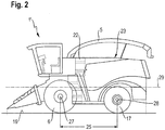
- Figure 2 describes a further forage harvester 1 ′ of the series of forage harvesters according to the invention which, in contrast to the forage harvester 1 , is equipped with individual wheels 6 on its front axle 27. Furthermore, the forage harvester 1 'is designed with main beams in the form of short beams 11 , which are shown in FIG Figure 2 are not shown. Regardless of the different shaped main beams, as well as various driving elements on the front axle 27 are the forage harvester 1, 1 'according to the Figures 1 and 2 at least substantially the same.
- the differences are limited to the different lengths of the forage harvester 1, 1 ′, with a center distance 25 between the front axle 27 and the rear axle 28 of the forage harvester 1 ′ falling below the center distance 24 of the forage harvester 1.
- the individual wheels 6 on the forage harvester 1 ′ take up a significantly smaller space in relation to a longitudinal extent in comparison to the crawler tracks 7 parallel to the longitudinal axis 29 of the forage harvester 1 '. Accordingly, it is not necessary to keep a length that would allow crawler tracks 7 to be installed on the forage harvester 1 '.
- the series according to the invention therefore has the particular advantage that the various forage harvesters 1, 1 ' differ from one another only in terms of a very small number of components, namely in particular with regard to the main girders used and those components which, due to a difference in length between the longitudinal girders 10 and the short beams 11 must be designed differently.
- This concerns for example, a housing 23 of a respective forage harvester 1, 1 '.
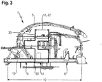
- the various main carriers of the variously designed forage harvesters 1, 1 'of the series according to the invention can be seen particularly well on the basis of the representations according to FIGS Figures 3 and 4th .
- These each show a support frame of a respective forage harvester 1 , 1 '.
- the forage harvester 1 according to the Figures 1 and 3rd is equipped with two main beams in the form of long beams 10 oriented in the longitudinal direction of the forage harvester 1 .
- These longitudinal beams 10 comprise a front section 8, a rear section 9 and a central section 14.
- the working elements of the forage harvester 1 are arranged in the front section 8.
- a drive device that is used in Figure 3 is not shown, is arranged in the rear section 9 .
- the middle section 14 as such has no technical significance, but serves solely to raise a length 12 of the longitudinal beam 10 to such a level that the forage harvester 1 can be equipped with crawler tracks 7 on its front axle 27.
- the middle section 14, which in turn has a length 15 serves to create space for crawler tracks 7.
- the main girders of such a forage harvester 1 ′ of the series according to the invention are formed in the form of short girders 11 .
- These include, comparable to the longitudinal girders 10, a front section 8 and a rear section 9, with the working organs in the front section 8 and in the rear section 9 the working organs in the rear section 9 also being comparable to the longitudinal girders 10 in FIG Figure 4 Not shown drive device of the forage harvester 1 ' are arranged.
- the long support 11 and the short member 10 only through the central portion 14 and the length of which differ 15.
Landscapes
- Life Sciences & Earth Sciences (AREA)
- Environmental Sciences (AREA)
- Engineering & Computer Science (AREA)
- Chemical & Material Sciences (AREA)
- Combustion & Propulsion (AREA)
- Transportation (AREA)
- Mechanical Engineering (AREA)
- Harvesting Machines For Specific Crops (AREA)
- Harvester Elements (AREA)
Description
Die vorliegende Erfindung betrifft eine Serie von Feldhäckslern, die von einer Vielzahl von Feldhäckslern gebildet ist. Weiterhin betrifft die vorliegende Anmeldung ein Verfahren zur Herstellung einer Serie von Feldhäckslern.The present invention relates to a series of forage harvesters, which is formed by a plurality of forage harvesters. The present application also relates to a method for producing a series of forage harvesters.
Serien von Feldhäckslern sind im Stand der Technik bereits bekannt. Diese umfassen jeweils eine Vielzahl von Feldhäckslern, die sich typischerweise durch eine hohe Anzahl von Gleichteilen auszeichnen. Unterschiede zwischen Feldhäckslern derselben Serie können beispielsweise in bestimmten Ausstattungsmerkmalen oder Leistungsabstufungen der jeweiligen Antriebseinrichtung bestehen.Series of forage harvesters are already known in the prior art. These each include a large number of forage harvesters, which are typically characterized by a large number of identical parts. Differences between forage harvesters of the same series can exist, for example, in certain equipment features or performance levels of the respective drive device.
Insbesondere ist es vorstellbar, dass verschiedene Feldhäcksler derselben Serie mit unterschiedlichen "Vortriebselementen" ausgestattet werden. Unter solchen werden im Sinne der vorliegenden Anmeldung diejenigen Elemente verstanden, mittels derer ein jeweiliger Feldhäcksler eine Relativbewegung gegenüber einem Untergrund ausführen kann, insbesondere mittels Abrollen. In aller Regel sind solche Vortriebselemente von typischen Einzelrädern in Form von Rundrädern oder von Raupenlaufwerken gebildet. Letztere umfassen typischerweise mehrere Räder, die von einem Laufgurt umspannt sind, wobei der Laufgurt die unmittelbare Übertragung einer Antriebskraft auf den Untergrund vornimmt. Dabei versteht es sich, dass Raupenlaufwerke eine gewisse axiale Länge bezogen auf eine Längsachse des jeweiligen Feldhäckslers aufweisen, die typischerweise einen Durchmesser eines "normalen" Einzelrades deutlich übersteigt. Mit anderen Worten weist ein Raupenlaufwerk in aller Regel an einem Feldhäcksler einen größeren Platzbedarf in Bezug auf dessen axiale Länge auf.In particular, it is conceivable that different forage harvesters of the same series are equipped with different "propulsion elements". In the context of the present application, such elements are understood to mean those elements by means of which a respective forage harvester can perform a relative movement with respect to a subsurface, in particular by means of rolling. As a rule, such propulsion elements are formed by typical single wheels in the form of round wheels or caterpillar tracks. The latter typically include several wheels that are spanned by a running belt, the running belt carrying out the direct transmission of a driving force to the ground. It goes without saying that caterpillars have a certain axial length in relation to a longitudinal axis of the respective forage harvester, which typically clearly exceeds the diameter of a “normal” individual wheel. In other words, a crawler track system generally requires a greater amount of space on a forage harvester in relation to its axial length.
Dies hat wiederum zur Folge, dass sowohl Raupenlaufwerke als auch Einzelräder nicht ohne Weiteres an Feldhäckslern ein und derselben Serie von Feldhäckslern angeordnet werden können. Abhilfe hierzu schafft beispielsweise die deutsche Offenlegungsschrift
Wenngleich die in der genannten Schrift beschriebene Technik eine maximale Flexibilität hinsichtlich der Verwendung verschiedener Vortriebselemente an ein und demselben Feldhäcksler verleiht, ist eine Umrüstung in der Praxis doch zumindest derart aufwendig, dass diese in vielen Fällen als zu komplex angesehen wird. Gleichzeitig wird die Notwendigkeit einer Umrüstung von Einzelrädern auf Raupenlaufwerke oder umgekehrt je nach Einzelfall oftmals für nicht ausreichend dringend angesehen als der notwendige Arbeitsaufwand zur Durchführung der Umrüstung auf sich genommen würde.Although the technology described in the cited document provides maximum flexibility with regard to the use of different propulsion elements on one and the same forage harvester, conversion is at least so expensive in practice that it is viewed as too complex in many cases. At the same time, the need to convert individual wheels to crawler tracks or vice versa, depending on the individual case, is often not viewed as urgently sufficient as the work required to carry out the conversion would be undertaken.
Der vorliegenden Erfindung liegt nunmehr die Aufgabe zugrunde, eine Serie von Feldhäckslern hervorzubringen, die eine Vereinbarkeit von Feldhäckslern mit Raupenlaufwerken und Feldhäckslern mit Einzelrädern innerhalb der Serie schafft.The present invention is now based on the object of producing a series of forage harvesters that make forage harvesters with caterpillar tracks and forage harvesters with individual wheels compatible within the series.
Die zugrunde liegende Aufgabe wird mittels einer Serie von Feldhäckslern mit den Merkmalen des Anspruchs 1 gelöst. Diese Serie umfasst mindestens einen Feldhäcksler, der einen Hauptträger in Form eines Langträgers umfasst. Dieser Langträger weist eine Länge auf, die eine Länge eines in Form eines Kurzträgers ausgebildeten Hauptträgers eines anderen Feldhäckslers der Serie übersteigt. Mit anderen Worten ist ein jeweiliger Langträger länger als ein jeweiliger Kurzträger, sodass diese einen Längenunterschied aufweisen. Sowohl ein jeweiliger Langträger als auch ein jeweiliger Kurzträger, die für die erfindungsgemäße Serie verwendet werden, weisen zumindest im Wesentlichen identisch ausgebildete Frontabschnitte und Heckabschnitte auf. Die Langträger verfügen zudem jeweils über einen Mittelabschnitt, den die Kurzträger nicht aufweisen. Im Ergebnis umfasst die Serie von Feldhäckslern mithin "lange Feldhäcksler" und "kurze Feldhäcksler", wobei die langen Feldhäcksler mit Hauptträgern in Form der Langträger und die kurzen Feldhäcksler mit Hauptträgern in Form der Kurzträger ausgestattet sind. Dies bedeutet auch, dass ein Umbau von einem langen Feldhäcksler hin zu einem kurzen Feldhäcksler oder umgekehrt, wie es in dem oben genannten Dokument zum Stand der Technik möglich ist, bei den Feldhäckslern der erfindungsgemäßen Serie nicht durchgeführt werden kann. Stattdessen sind die einmal mit ihren jeweiligen Hauptträgern ausgestatteten Feldhäcksler der Serie dauerhaft entweder lang oder kurz.The underlying object is achieved by means of a series of forage harvesters having the features of claim 1. This series includes at least one forage harvester, which includes a main beam in the form of a long beam. This solebar has a length which exceeds a length of a main girder in the form of a short girder of another forage harvester in the series. In other words, a respective long girder is longer than a respective short girder, so that these have a difference in length. Both a respective long girder and a respective short girder which are used for the series according to the invention have at least essentially identically designed front sections and rear sections. The solebars also each have a central section that the short girders do not have. As a result, the series of forage harvesters includes "long forage harvesters" and "short forage harvesters", the long forage harvesters being equipped with main carriers in the form of long carriers and the short forage harvesters with main carriers in the form of short carriers. This also means that a conversion from a long forage harvester to a short forage harvester or vice versa, as is possible in the above-mentioned prior art document, cannot be carried out with the forage harvesters of the series according to the invention. Instead, the forage harvesters of the series, once equipped with their respective main carriers, are permanently either long or short.
Unter einer "Serie von Feldhäckslern" wird im Sinne der vorliegenden Anmeldung eine Vielzahl von Feldhäckslern grundsätzlich gleichen Aufbaus verstanden, die sich lediglich durch singuläre Merkmale voneinander unterscheiden. Insbesondere weisen sämtliche Feldhäcksler einer Serie eine Vielzahl von Gleichteilen auf, wobei typischerweise mindestens 90 % der verwendeten Bauteile, die übergreifend über alle Feldhäcksler der Serie verwendet werden, identisch sind. Es versteht sich, dass sämtliche Feldhäcksler einer Serie in aller Regel von ein und demselben Hersteller stammen.In the context of the present application, a “series of forage harvesters” is understood to mean a plurality of forage harvesters which are basically of the same design and differ from one another only in terms of singular features. In particular, all forage harvesters in a series have a large number of identical parts, with typically at least 90% of the components used, which are used across all forage harvesters in the series, being identical. It goes without saying that all forage harvesters in a series generally come from one and the same manufacturer.
Die Feldhäcksler der erfindungsgemäßen Serie umfassen jeweils mindestens eine Antriebseinrichtung, wobei unter einer solchen im Sinne der vorliegenden Anmeldung in aller Regel ein Verbrennungsmotor verstanden wird, der dazu geeignet ist, mindestens eines der Vortriebselemente sowie die typischen Arbeitsorgane eines jeweiligen Feldhäckslers anzutreiben. Als solches ist insbesondere das Häckselorgan zu nennen, mittels dessen jeweiliges Erntegut gehäckselt werden kann.The forage harvesters of the series according to the invention each comprise at least one drive device, such as in the context of the present application generally being understood to mean an internal combustion engine which is suitable for driving at least one of the propulsion elements and the typical working elements of a respective forage harvester. As such, the chopping organ is to be mentioned in particular, by means of which the respective crop can be chopped.
Die Arbeitsorgane und die Antriebseinrichtung sind jeweils auf mindestens einem durchlaufenden Hauptträger angeordnet, typischerweise werden zwei parallel zueinander verlaufende sowie voneinander beabstandete Hauptträger verwendet. Letztere sind in der erfindungsgemäßen Weise bei mindestens einem Feldhäcksler der Serie als Langträger sowie bei mindestens einem anderen Feldhäcksler der Serie als Kurzträger ausgebildet. Der bzw. die Hauptträger dienen dazu, die an ihm montierten Bauteile zu tragen, das heißt Gewichtskräfte dieser Bauteile abzuleiten. Insbesondere werden die Gewichtskräfte in Richtung der Vortriebselemente und schließlich mittels der Vortriebselemente in den Untergrund eingeleitet.The working members and the drive device are each arranged on at least one continuous main carrier, typically two main carriers running parallel to one another and spaced apart from one another are used. In the manner according to the invention, the latter are designed as a long beam in at least one forage harvester of the series and as a short beam in at least one other forage harvester of the series. The main girder or girders serve to carry the components mounted on it, that is to say to dissipate the weight forces of these components. In particular, the weight forces are introduced into the ground in the direction of the propulsion elements and finally by means of the propulsion elements.
Wie eingangs bereits beschrieben, werden unter "Vortriebselementen" im Sinne der vorliegenden Anmeldung diejenigen Elemente verstanden, mittels derer ein jeweiliger Feldhäcksler eine Bewegung relativ zu dem Untergrund ausführen kann. Insbesondere können die Vortriebselemente in Form von Einzelrädern bzw. Rundrädern oder von Raupenlaufwerken gebildet sein. Weiterhin ist mindestens eines, vorzugsweise mehrere, der Vortriebselemente zumindest mittelbar mit der Antriebseinrichtung verbunden, sodass das jeweilige Vortriebselement - und mithin der gesamte Feldhäcksler - antreibbar ist.As already described at the beginning, “propulsion elements” in the sense of the present application are understood to mean those elements by means of which a respective forage harvester can execute a movement relative to the ground. In particular, the propulsion elements can be in the form of individual wheels or round wheels or caterpillar tracks. Furthermore, at least one, preferably several, of the propulsion elements is at least indirectly connected to the drive device, so that the respective propulsion element - and therefore the entire forage harvester - can be driven.
Unter einem "Raupenlaufwerk" wird dabei im Sinne der vorliegenden Anmeldung ein Vortriebselement verstanden, dass zwei einander gegenüberliegende Haupträder aufweist, die von einem Laufgurt umspannt sind, wobei zwischen den Haupträdern mindestens ein Hilfsrad angeordnet ist, dessen Durchmesser in aller Regel die Durchmesser der Haupträder deutlich unterschreitet. Die Haupträder eines Raupenlaufwerks weisen typischerweise denselben Durchmesser auf, sodass sich der Laufgurt in einem Bereich zwischen den Haupträdern zumindest im Wesentlichen parallel zu einer Aufstandsfläche des Raupenlaufwerks erstreckt. Das mindestens eine Hilfsrad dient dazu, den Laufgurt im Bereich zwischen den Haupträdern "niederzuhalten". Hierzu wirkt das Hilfsrads mit einem unteren Abschnitt des Laufgurts zusammen, wobei auf das Raupenlaufwerk wirkende Kräfte zusätzlich zu den Haupträdern auch mittels des Hilfsrades in den Untergrund einleitbar sind und somit insgesamt eine Krafteinleitung von dem Raupenlaufwerk in den Untergrund sich über eine vergleichsweise große Fläche des Laufgurts verteilt. Hierin ist der wesentliche Unterschied zur Kraftableitung eines Einzelrades zu sehen, dessen Krafteinleitungsfläche im Vergleich zu einem Raupenlaufwerk sehr gering ist, sodass ein solches Einzelrad eine vergleichsweise hohe Flächenpressung auf den jeweiligen Untergrund ausübt.In the context of the present application, a "caterpillar drive" is understood to mean a propulsion element that has two opposing main wheels that are spanned by a running belt, with at least one auxiliary wheel being arranged between the main wheels, the diameter of which is generally the diameter of the main wheels falls below. The main wheels of a crawler drive typically have the same diameter, so that the running belt extends in an area between the main wheels at least substantially parallel to a contact surface of the crawler drive. The at least one auxiliary wheel is used to "hold down" the running belt in the area between the main wheels. For this purpose, the auxiliary wheel interacts with a lower section of the running belt, with forces acting on the crawler track system in addition to the main wheels also being able to be introduced into the ground by means of the auxiliary wheel, and thus an overall introduction of force from the crawler belt unit into the ground over a comparatively large area of the running belt distributed. Herein is the essential The difference to the force dissipation of a single wheel can be seen, the force introduction surface of which is very small compared to a crawler track, so that such a single wheel exerts a comparatively high surface pressure on the respective ground.
Die erfindungsgemäße Serie hat viele Vorteile. Insbesondere ermöglicht sie es, verschiedene Feldhäcksler derselben Serie mit verschiedenen Vortriebselementen auszustatten, wobei diejenigen Feldhäcksler der Serie, die mit mindestens einem Hauptträger in Form eines Langträgers ausgebildet sind, vorteilhafterweise zumindest beidseits ihrer Vorderachse mit Vortriebselementen in Form von Raupenlaufwerken zusammenwirken. Gleichzeitig wirken diejenigen Feldhäcksler, die mit mindestens einem Kurzträger ausgebildet sind, vorteilhafterweise an ihrer jeweiligen Vorderachse mit Einzelrädern zusammen. Mithin müssen sich die verschiedenen Feldhäcksler der erfindungsgemäßen Serie zumindest im Wesentlichen lediglich im Umfang der verschieden ausgeführten Hauptträger sowie der verschiedenen (vorderen) Vortriebselemente unterscheiden, während die Feldhäcksler über die gesamte Serie hinweg im Übrigen zumindest im Wesentlichen, vorzugsweise vollständig, identisch ausgebildet sein können.The series of the invention has many advantages. In particular, it makes it possible to equip different forage harvesters of the same series with different propulsion elements, with those forage harvesters of the series that are designed with at least one main beam in the form of a longitudinal beam, advantageously cooperating with propulsion elements in the form of caterpillars at least on both sides of their front axle. At the same time, those forage harvesters which are designed with at least one short carrier advantageously interact with individual wheels on their respective front axle. The various forage harvesters of the series according to the invention must therefore differ at least essentially only in the scope of the differently designed main girders and the various (front) propulsion elements, while the forage harvesters can otherwise be designed at least essentially, preferably completely, identically over the entire series.
Hierbei versteht es sich, dass kleinere Unterschiede, die einzig und allein auf den Längenunterschied zwischen den verschiedenen Feldhäckslern zurückzuführen sind, im Sinne der vorliegenden Anmeldung nicht als "wesentliche Unterschiede" angesehen werden. Insbesondere ist es denkbar, dass Bauteilträger, an denen innerhalb eines jeweiligen Feldhäckslers verschiedene funktionale Einheiten angeordnet sind, bei Verwendung eines Langträgers als Hauptträger ebenfalls innerhalb des Feldhäckslers länger ausgebildet sein müssen als ein entsprechender Bauteilträger bei einem kurzen Feldhäcksler. Gleichwohl sind jedoch zumindest die Antriebseinrichtung sowie sämtliche Arbeitsorgane sämtlicher Feldhäcksler der erfindungsgemäßen Serie unabhängig davon, welche Hauptträger jeweils verwendet werden, identisch. Dasselbe gilt beispielsweise für die Fahrerkabine und eine Reihe weiterer Bauteile, beispielsweise des Antriebsstrangs. Dies schließt somit auch Fälle mit ein, bei denen beispielsweise verschiedene Feldhäcksler der Serie mit verschiedenen Vorsatzgeräten, beispielsweise mit solchen unterschiedlicher Breite, ausgestattet sind. Es versteht sich, dass derartig verschiedene Vorsatzgeräte unabhängig davon an einem jeweiligen Feldhäcksler angeordnet werden können, ob dieser mit einem Hauptträger in Form eines Langträgers oder einen solchen in Form eines Kurzträgers ausgestattet ist.It goes without saying that minor differences, which are solely due to the difference in length between the various forage harvesters, are not regarded as "essential differences" in the context of the present application. In particular, it is conceivable that component carriers on which various functional units are arranged within a respective forage harvester must also be longer within the forage harvester than a corresponding component carrier in a short forage harvester when using a longitudinal carrier as the main carrier. At the same time, however, at least the drive device and all working elements of all forage harvesters of the series according to the invention are identical regardless of which main carrier is used in each case. The same applies, for example, to the driver's cab and a number of other components, such as the drive train. This also includes cases in which, for example, different forage harvesters of the series are equipped with different attachments, for example with those of different widths. It goes without saying that attachments of this type can be arranged on a respective forage harvester regardless of whether this is equipped with a main beam in the form of a long beam or one in the form of a short beam.
Die erfindungsgemäße Serie bietet folglich den besonderen Vorteil, dass im Zuge der Herstellung der einzelnen Feldhäcksler ohne Weiteres zwischen solchen, die lang ausgebildet werden sollen, und solchen, die kurz ausgebildet werden sollen, gewechselt werden kann. Der im Wesentlichen einzige Unterschied besteht nämlich darin, als Hauptträger entweder einen Langträger oder einen Kurzträger zu verwenden. Bezogen auf die gewünschte Auswahl der Vortriebselemente kann in der Praxis mithin zwischen langen "Raupenhäckslern" und kurzen "Radhäckslern" unterschieden werden, ohne dass hierfür in der Produktion irgendeine Umstellung oder sonstiger Aufwand notwendig ist.The series according to the invention consequently offers the particular advantage that in the course of the manufacture of the individual forage harvesters it is easy to switch between those that are to be made long and those that are to be made short. Basically the only difference is when Main beam to use either a long beam or a short beam. With regard to the desired selection of the propulsion elements, a distinction can be made in practice between long "caterpillar choppers" and short "wheel choppers" without any conversion or other effort being necessary for this in production.
In einer vorteilhaften Ausgestaltung der erfindungsgemäßen Serie entspricht eine Länge des Mittelabschnitts eines jeweiligen Langträgers zumindest im Wesentlichen, vorzugsweise vollständig, dem Längenunterschied zwischen dem Langträger und einen jeweiligen Kurzträger. Mit anderen Worten sind die Langträger genau um das Maß länger als die Kurzträger, das einer Länge eines Mittelabschnitts eines jeweiligen Langträgers entspricht. Bei entsprechend ausgebildeten Hauptträgern ist es besonders einfach möglich, die Frontabschnitte und die Heckabschnitte unabhängig von der Länge des jeweiligen Hauptträger identisch auszubilden.In an advantageous embodiment of the series according to the invention, a length of the central section of a respective solebar corresponds at least substantially, preferably completely, to the difference in length between the solebar and a respective short bearer. In other words, the solebars are exactly longer than the short bearers by the amount that corresponds to a length of a central section of a respective solebar. With appropriately designed main girders, it is particularly easy to design the front sections and the rear sections identically regardless of the length of the respective main girder.
Weiterhin ist eine solche Ausgestaltung der erfindungsgemäßen Serie von Vorteil, bei der die Hauptträger serienübergreifend einstückig ausgebildet sind. Eine Umrüstung, beispielsweise in Form einer modularen Gestaltung wie sie aus dem Stand der Technik bekannt ist, ist mithin nicht möglich. Diese ist jedoch auch nicht erforderlich bzw. gewünscht, da der Aufwand zur Umrüstung eines einzelnen Feldhäckslers von einem langen Feldhäcksler hin zu einem kurzen Feldhäcksler oder umgekehrt schlicht zu groß ist. Auch sind die hierfür erforderlichen Bauteile nicht in derselben Weise wirtschaftlich herstellbar, wie die für die erfindungsgemäße Serie verwendeten Hauptträger. Dasselbe gilt für die Fertigung derartiger Feldhäcksler.Furthermore, such an embodiment of the series according to the invention is advantageous in which the main carriers are formed in one piece across the series. A conversion, for example in the form of a modular design as is known from the prior art, is therefore not possible. However, this is also not necessary or desired, since the effort to convert an individual forage harvester from a long forage harvester to a short forage harvester or vice versa is simply too great. The components required for this cannot be produced economically in the same way as the main girders used for the series according to the invention. The same applies to the manufacture of such forage harvesters.
In verfahrenstechnischer Hinsicht wird die zugrunde liegende Aufgabe mittels eines Verfahrens zur Herstellung einer Serie von Feldhäckslern mit den Verfahrensschritten gemäß Anspruch 4 gelöst. Dieses Verfahren sieht vor, dass im Zuge der Herstellung eines jeweiligen Feldhäckslers der Serie entweder mindestens ein Hauptträger in Form eines Kurzträgers oder mindestens ein Hauptträger in Form eines Langträgers ausgewählt und sodann im Weiteren verwendet wird. Dabei versteht es sich, dass bei einem jeweiligen Feldhäcksler entweder sämtliche Hauptträger von Langträgern oder sämtliche Hauptträger von Kurzträgern gebildet sind. Weiterhin werden im Rahmen der Herstellung diejenigen Feldhäcksler, deren Hauptträger von mindestens einem Langträger gebildet ist bzw. sind, mit Vortriebselementen in Form von Raupenlaufwerken ausgestattet. Umgekehrt werden diejenigen Feldhäcksler der Serie, die mit Kurzträgern ausgestattet sind, mit Vortriebselementen in Form von Einzelrädern ausgestattet.From a procedural point of view, the underlying object is achieved by means of a method for producing a series of forage harvesters with the method steps according to
Mittels des erfindungsgemäßen Verfahrens die erfindungsgemäße Serie von Feldhäckslern besonders einfach herstellbar. Dabei bietet das Verfahren die vorstehend bereits erläuterten Vorteile, nämlich die besonders einfache Handhabung der Produktion, wobei zur Unterscheidung zwischen einem langen Feldhäcksler und einem kurzen Feldhäcksler im Wesentlichen lediglich zwischen den verschiedenen Hauptträgern gewählt werden muss. Die Frontabschnitte und die Heckabschnitte dieser Hauptträger sind unabhängig von deren Länge, das heißt unabhängig von der Anwesenheit eines Mittelabschnitts beim Langträger, zumindest im Wesentlichen, vorzugsweise vollständig, identisch ausgebildet sodass die Herstellung eines langen Feldhäckslers fast vollständig gleichlaufend einer solchen eines kurzen Feldhäckslers ablaufen kann. Dies ist sowohl im Hinblick auf besonders wirtschaftliche Produktionsbedingungen wie auch eine niedrige Fehleranfälligkeit der Produktion der Serie insgesamt von erheblichem Vorteil. Insbesondere sind die Arbeitsschritte und Arbeitsabläufe fast vollständig unabhängig davon, welche Art von Hauptträger letztlich für einen jeweiligen Feldhäcksler der Serie verbaut wird. Ferner ist das Umschalten der Produktion von "Raupenhäckslern" zu "Radhäckslern" oder umgekehrt besonders einfach möglich, ohne dass die Produktionsstraße umfassend verändert oder angepasst werden muss.By means of the method according to the invention, the series of forage harvesters according to the invention can be manufactured particularly easily. The method offers the advantages already explained above, namely the particularly simple handling of the production, whereby in order to distinguish between a long forage harvester and a short forage harvester essentially only one has to choose between the various main carriers. The front sections and the rear sections of these main girders are designed to be at least substantially, preferably completely, identical regardless of their length, i.e. regardless of the presence of a middle section in the long girder, so that the production of a long forage harvester can run almost completely concurrently with that of a short forage harvester. This is of considerable advantage both in terms of particularly economical production conditions and a low susceptibility to errors in the production of the series as a whole. In particular, the work steps and workflows are almost completely independent of which type of main beam is ultimately installed for a particular forage harvester in the series. Furthermore, it is particularly easy to switch the production from “caterpillar choppers” to “wheel choppers” or vice versa, without the production line having to be comprehensively changed or adapted.
Die erfindungsgemäße Serie sowie das erfindungsgemäße Verfahren werden nachstehend anhand eines Ausführungsbeispiels, das in den Figuren dargestellt ist, näher erläutert. Es zeigt:
- Fig. 1:
- Eine Seitenansicht einen "Raupenhäckslers" einer erfindungsgemäßen Serie von Feldhäckslern,
- Fig. 2:
- Eine Seitenansicht eines "Radhäckslers" der erfindungsgemäßen Serie,
- Fig. 3:
- Eine Seitenansicht eines Skeletts des Raupenhäckslers gemäß
Figur 1 und - Fig. 4:
- Eine Seitenansicht eines Skeletts des Radhäckslers gemäß
Figur 2
- Fig. 1:
- A side view of a "caterpillar chopper" of a series of forage harvesters according to the invention,
- Fig. 2:
- A side view of a "wheel chopper" of the series according to the invention,
- Fig. 3:
- A side view of a skeleton of the caterpillar chopper according to FIG
Figure 1 and - Fig. 4:
- A side view of a skeleton of the wheel chopper according to FIG
Figure 2 .
Das Ausführungsbeispiel, das in den
Im Übrigen ist der Feldhäcksler 1 mit einem Förderorgan 3, einem Häckselorgan 4, einem Beschleunigungsorgans 18 und einem Ausruforgan 5 ausgestattet. Diese Organe bilden gemeinsam die Arbeitsorgane des Feldhäckslers 1, mittels derer letzterer dazu geeignet ist, Erntegut 2 zu ernten und zu verarbeiten. An seiner Hinterachse 28 ist der Feldhäcksler 1 beidseits jeweils mit einem Hinterrad 17 ausgestattet. Die Hinterräder 17 sind hier in Form üblicher Einzelräder ausgebildet. Die Vorderachse 27 und die Hinterachse 28 des Feldhäckslers 1 befinden sich in einem parallel zu einer Längsachse 29 des Feldhäckslers 1 gemessenen Achsabstand 24. In addition, the forage harvester 1 is equipped with a conveying
Die Raupenlaufwerke 7 sowie die Hinterräder 17 bilden jeweils Vortriebselemente des Feldhäckslers 1, mittels derer der Feldhäcksler 1 unmittelbar auf einem Untergrund 16 aufsteht. Die Vortriebselemente befähigen den Feldhäcksler 1 dazu, sich relativ zu dem Untergrund 16 zu bewegen. Wie sich anhand der Darstellung gemäß
Genannte
Die erfindungsgemäße Serie hat mithin den besonderen Vorteil, dass sich die verschiedenen Feldhäcksler 1, 1' nur im Umfang einer sehr geringen Anzahl von Bauteilen voneinander unterscheiden, nämlich insbesondere im Hinblick auf die verwendeten Hauptträger sowie solche Bauteile, die aufgrund einer Längendifferenz zwischen den Langträgern 10 und den Kurzträgern 11 unterschiedlich ausgebildet werden müssen. Dies betrifft beispielsweise ein Gehäuse 23 eines jeweiligen Feldhäckslers 1, 1'. The series according to the invention therefore has the particular advantage that the various forage harvesters 1, 1 ' differ from one another only in terms of a very small number of components, namely in particular with regard to the main girders used and those components which, due to a difference in length between the
Die verschiedenen Hauptträger der verschiedenartig ausgebildeten Feldhäcksler 1, 1' der erfindungsgemäßen Serie ergeben sich besonders gut anhand der Darstellungen gemäß den
Entsprechend versteht es sich, dass ein solcher Raum an einem Feldhäcksler 1', der an seiner Vorderachse 27 mit Einzelrädern 6 ausgestattet werden soll, nicht erforderlich ist. Entsprechend sind Hauptträger eines solchen Feldhäckslers 1' der erfindungsgemäßen Serie in Form von Kurzträgern 11 gebildet. Diese umfassen vergleichbar zu den Langträgern 10 einen Frontabschnitt 8 sowie einen Heckabschnitt 9, wobei ebenfalls in gleicher Weise vergleichbar zu den Langträgern 10 in dem Frontabschnitt 8 die Arbeitsorgane und in dem Heckabschnitt 9 die in
Anhand der Darstellungen gemäß den
- 1, 1'1, 1 '
- FeldhäckslerForage harvester
- 22
- ErntegutCrop
- 33
- FörderorganFunding body
- 44th
- HäckselorganChopping organ
- 55
- AuswurforganEjection organ
- 66th
- EinzelradSingle wheel
- 77th
- RaupenlaufwerkCaterpillar drive
- 88th
- FrontabschnittFront section
- 99
- HeckabschnittStern section
- 1010
- LangträgerLong beams
- 1111
- KurzträgerShort beam
- 1212th
- Länge des LangträgersLength of the solebar
- 1313th
- Länge des KurzträgersLength of the short beam
- 1414th
- MittelabschnittMiddle section
- 1515th
- Länge des MittelabschnittsLength of the middle section
- 1616
- UntergrundUnderground
- 1717th
- HinterradRear wheel
- 1818th
- BeschleunigungsorganAccelerator
- 1919th
- HauptradMain wheel
- 2020th
- LaufgurtRunning belt
- 2121
- HilfsradAuxiliary wheel
- 2222nd
- DifferenzbereichDifference range
- 2323
- Gehäusecasing
- 2424
- AchsabstandCenter distance
- 2525th
- AchsabstandCenter distance
- 2626th
- TrennebeneParting plane
- 2727
- VorderachseFront axle
- 2828
- HinterachseRear axle
- 2929
- LängsachseLongitudinal axis
- 3030th
- Linieline
Claims (4)
- A series of forage harvesters (1, 1') comprising a plurality of forage harvesters (1, 1') for chopping crop (2) located on a working field, each of the forage harvesters (1, 1') comprising- at least one operating unit in the form of a conveyor unit (3) for conveying cut crop (2) in the direction of a chopping unit (4),- at least one operating unit in the form of a chopping unit (4) for chopping the cut crop (2),- at least one drive device for driving at least one propulsion element, in particular an independent wheel (6) or a track roller unit (7), as well as the operating unit, and also- at least one continuous main beam for receiving the operating units as well as the drive device,wherein, by means of the main beam, at least a proportion of the weight forces of the operating units and of the drive device can be dissipated,
wherein the operating units are at least indirectly connected in a front section (8) and the drive device is at least indirectly connected in a rear section (9) of the main beam in the same force-transmitting manner,
characterized in that
a main beam of a forage harvester (1) of the series constructed in the form of a long beam (10) has a length (12) which exceeds a length (13) of a main beam of another forage harvester (1') of the series constructed in the form of a short beam (11), so that the long beam (10) and the short beam (11) are different in length,
wherein both the long beam (10) as well as the short beam (11) have at least substantially identically constructed front sections (8) and rear sections (9), and
wherein the long beam (10) has an additional central section (14) compared to the short beam (11),
wherein all of the forage harvesters (1) of the series which are equipped with long beams (10) are equipped with propulsion elements in the form of track roller units (7) on at least their front axles, and wherein all of the forage harvesters of the series which are equipped with a short beam (11) are equipped with propulsion elements in the form of independent wheels (6) on their front axles. - The series according to claim 1, characterized in that a length (15) of the central section (14) substantially corresponds, preferably completely corresponds, to the difference in length between the long beam (10) and the short beam (11).
- The series according to claim 1 or claim 2, characterized in that the long beam (10) and the short beam (11) are constructed as single pieces.
- A method for the manufacture of a series of forage harvesters (1, 1'), comprising the following steps of the method:a) operating units of the respective forage harvester (1, 1') are at least indirectly mounted in or on a front section (8) of a main beam,b) a drive device of a respective forage harvester (1, 1') of the series is mounted in a rear section (9) of the main beam,c) propulsion elements, in particular independent wheels (6) and/or track roller units (7), by means of which the completed forage harvester (1, 1') can come into direct contact with the ground (16), are at least indirectly connected to the main beam so that forces acting on the forage harvester (1, 1') can be transmitted onto the propulsion elements and eventually onto the ground (16) by means of the main beam,characterized by the following steps of the method:d) during the manufacture of at least one forage harvester (1') of the series, a main beam in the form of a short beam (11) is selected and used in the further method wherein the forage harvester (1') produced in this manner is provided with propulsion elements in the form of independent wheels (6), at least on its front axle,e) during the manufacture of at least one other forage harvester (1) of the series, a main beam in the form of a long beam (10) is selected and used in the further method wherein the forage harvester (1) produced in this manner is provided with propulsion elements in the form of track roller units (7), at least on its front axle,wherein a length (12) of the long beam (10) exceeds a length (13) of the short beam (11),
wherein both the long beam (10) as well as the short beam (11) have at least substantially identically constructed front sections (8) and rear sections (9), and
wherein the long beam (10) has an additional central section (14) compared to the short beam (11).
Applications Claiming Priority (1)
| Application Number | Priority Date | Filing Date | Title |
|---|---|---|---|
| DE102017119792.3A DE102017119792A1 (en) | 2017-08-29 | 2017-08-29 | Series of forage harvesters and methods for their production |
Publications (2)
| Publication Number | Publication Date |
|---|---|
| EP3449714A1 EP3449714A1 (en) | 2019-03-06 |
| EP3449714B1 true EP3449714B1 (en) | 2021-07-21 |
Family
ID=62486474
Family Applications (1)
| Application Number | Title | Priority Date | Filing Date |
|---|---|---|---|
| EP18174855.9A Active EP3449714B1 (en) | 2017-08-29 | 2018-05-29 | Series of forage harvesters and method for the production thereof |
Country Status (2)
| Country | Link |
|---|---|
| EP (1) | EP3449714B1 (en) |
| DE (1) | DE102017119792A1 (en) |
Families Citing this family (1)
| Publication number | Priority date | Publication date | Assignee | Title |
|---|---|---|---|---|
| DE102019215146A1 (en) | 2019-10-01 | 2021-04-01 | Deere & Company | Forage harvester with a supporting frame |
Family Cites Families (5)
| Publication number | Priority date | Publication date | Assignee | Title |
|---|---|---|---|---|
| US5290201A (en) * | 1992-06-11 | 1994-03-01 | Tesker Henry L | Combine with mmoveable body and tandem drive wheels |
| DE10150052B4 (en) * | 2001-10-10 | 2005-07-14 | Daimlerchrysler Ag | Chassis for commercial vehicles |
| DE10327478A1 (en) * | 2003-06-18 | 2005-02-03 | Deere & Company, Moline | Self-propelled harvester |
| DE102008033067A1 (en) | 2008-07-15 | 2010-01-21 | Claas Selbstfahrende Erntemaschinen Gmbh | Agricultural harvester |
| DE102008059467A1 (en) * | 2008-11-28 | 2010-06-10 | Claas Selbstfahrende Erntemaschinen Gmbh | Agricultural tractor |
-
2017
- 2017-08-29 DE DE102017119792.3A patent/DE102017119792A1/en not_active Withdrawn
-
2018
- 2018-05-29 EP EP18174855.9A patent/EP3449714B1/en active Active
Also Published As
| Publication number | Publication date |
|---|---|
| EP3449714A1 (en) | 2019-03-06 |
| DE102017119792A1 (en) | 2019-02-28 |
Similar Documents
| Publication | Publication Date | Title |
|---|---|---|
| EP1789299B1 (en) | Maintenance vehicle | |
| DD156685A5 (en) | HYDRAULIC ENGINE DRIVEN TWO-PIECE UNILOGRAPHIC VEHICLE | |
| DE102009009097A1 (en) | walking beam conveyor | |
| EP2392524A1 (en) | Channel storage with rails for guiding a satellite car | |
| EP1942065A1 (en) | Lifting bar conveyor | |
| DE102014004681B4 (en) | Conveyor train with roll suppressor | |
| EP3464019B1 (en) | Verification of the integrity of a train of vehicles | |
| EP3449714B1 (en) | Series of forage harvesters and method for the production thereof | |
| DE4322263C5 (en) | A method of preparing a ground vehicle traveling work vehicle with a road operation implement and implement for placement on such a work vehicle | |
| DE102015014861A1 (en) | Automated felling process for forestry and working machine therefor | |
| DE2047400A1 (en) | Transportation facility | |
| DE102011112180A1 (en) | Floor structure for body of e.g. small passenger car, has reinforced structure comprising strut pairs with reinforcement struts arranged next to each other in vehicle transverse directions, where struts are fixed at structure components | |
| DE2837191A1 (en) | CHASSIS FOR ATTRACTION MAGNETIC LIFT VEHICLES | |
| EP2639354B1 (en) | Tracked piste preparation vehicle for snow surface processing | |
| DE102014008086A1 (en) | Supporting device for supporting a drive unit on a passenger car body | |
| DE202009006630U1 (en) | lifting device | |
| DE102018117214A1 (en) | Reach truck with a monitoring sensor and a method for operating such | |
| EP3449713A1 (en) | Field chopper and method for retrofitting the same | |
| DE102019203758B4 (en) | Structural component for a body of a vehicle and vehicle body | |
| DE202012004683U1 (en) | agricultural machinery | |
| DE1756629A1 (en) | Loading device | |
| EP3221518B1 (en) | Sectional lane-supporting bridge, and method for laying a sectional lane-supporting bridge | |
| EP3293097B1 (en) | Reinforcement for a wheel set for a self-propelled harvester | |
| DE102015215507A1 (en) | Motor vehicle body with a longitudinal beam receiving, adhesive technically joined console | |
| DE102016201467A1 (en) | Motor vehicle with deformable vehicle front |
Legal Events
| Date | Code | Title | Description |
|---|---|---|---|
| PUAI | Public reference made under article 153(3) epc to a published international application that has entered the european phase |
Free format text: ORIGINAL CODE: 0009012 |
|
| STAA | Information on the status of an ep patent application or granted ep patent |
Free format text: STATUS: THE APPLICATION HAS BEEN PUBLISHED |
|
| AK | Designated contracting states |
Kind code of ref document: A1 Designated state(s): AL AT BE BG CH CY CZ DE DK EE ES FI FR GB GR HR HU IE IS IT LI LT LU LV MC MK MT NL NO PL PT RO RS SE SI SK SM TR |
|
| AX | Request for extension of the european patent |
Extension state: BA ME |
|
| STAA | Information on the status of an ep patent application or granted ep patent |
Free format text: STATUS: REQUEST FOR EXAMINATION WAS MADE |
|
| 17P | Request for examination filed |
Effective date: 20190906 |
|
| RBV | Designated contracting states (corrected) |
Designated state(s): AL AT BE BG CH CY CZ DE DK EE ES FI FR GB GR HR HU IE IS IT LI LT LU LV MC MK MT NL NO PL PT RO RS SE SI SK SM TR |
|
| RIC1 | Information provided on ipc code assigned before grant |
Ipc: A01D 67/00 20060101AFI20201210BHEP Ipc: A01D 43/08 20060101ALI20201210BHEP Ipc: B62D 55/04 20060101ALI20201210BHEP |
|
| GRAP | Despatch of communication of intention to grant a patent |
Free format text: ORIGINAL CODE: EPIDOSNIGR1 |
|
| STAA | Information on the status of an ep patent application or granted ep patent |
Free format text: STATUS: GRANT OF PATENT IS INTENDED |
|
| INTG | Intention to grant announced |
Effective date: 20210205 |
|
| GRAS | Grant fee paid |
Free format text: ORIGINAL CODE: EPIDOSNIGR3 |
|
| GRAA | (expected) grant |
Free format text: ORIGINAL CODE: 0009210 |
|
| STAA | Information on the status of an ep patent application or granted ep patent |
Free format text: STATUS: THE PATENT HAS BEEN GRANTED |
|
| AK | Designated contracting states |
Kind code of ref document: B1 Designated state(s): AL AT BE BG CH CY CZ DE DK EE ES FI FR GB GR HR HU IE IS IT LI LT LU LV MC MK MT NL NO PL PT RO RS SE SI SK SM TR |
|
| REG | Reference to a national code |
Ref country code: GB Ref legal event code: FG4D Free format text: NOT ENGLISH |
|
| REG | Reference to a national code |
Ref country code: CH Ref legal event code: EP |
|
| REG | Reference to a national code |
Ref country code: DE Ref legal event code: R096 Ref document number: 502018006186 Country of ref document: DE |
|
| REG | Reference to a national code |
Ref country code: AT Ref legal event code: REF Ref document number: 1411715 Country of ref document: AT Kind code of ref document: T Effective date: 20210815 |
|
| REG | Reference to a national code |
Ref country code: IE Ref legal event code: FG4D Free format text: LANGUAGE OF EP DOCUMENT: GERMAN |
|
| REG | Reference to a national code |
Ref country code: LT Ref legal event code: MG9D |
|
| REG | Reference to a national code |
Ref country code: NL Ref legal event code: MP Effective date: 20210721 |
|
| PG25 | Lapsed in a contracting state [announced via postgrant information from national office to epo] |
Ref country code: ES Free format text: LAPSE BECAUSE OF FAILURE TO SUBMIT A TRANSLATION OF THE DESCRIPTION OR TO PAY THE FEE WITHIN THE PRESCRIBED TIME-LIMIT Effective date: 20210721 Ref country code: FI Free format text: LAPSE BECAUSE OF FAILURE TO SUBMIT A TRANSLATION OF THE DESCRIPTION OR TO PAY THE FEE WITHIN THE PRESCRIBED TIME-LIMIT Effective date: 20210721 Ref country code: HR Free format text: LAPSE BECAUSE OF FAILURE TO SUBMIT A TRANSLATION OF THE DESCRIPTION OR TO PAY THE FEE WITHIN THE PRESCRIBED TIME-LIMIT Effective date: 20210721 Ref country code: RS Free format text: LAPSE BECAUSE OF FAILURE TO SUBMIT A TRANSLATION OF THE DESCRIPTION OR TO PAY THE FEE WITHIN THE PRESCRIBED TIME-LIMIT Effective date: 20210721 Ref country code: SE Free format text: LAPSE BECAUSE OF FAILURE TO SUBMIT A TRANSLATION OF THE DESCRIPTION OR TO PAY THE FEE WITHIN THE PRESCRIBED TIME-LIMIT Effective date: 20210721 Ref country code: PT Free format text: LAPSE BECAUSE OF FAILURE TO SUBMIT A TRANSLATION OF THE DESCRIPTION OR TO PAY THE FEE WITHIN THE PRESCRIBED TIME-LIMIT Effective date: 20211122 Ref country code: NL Free format text: LAPSE BECAUSE OF FAILURE TO SUBMIT A TRANSLATION OF THE DESCRIPTION OR TO PAY THE FEE WITHIN THE PRESCRIBED TIME-LIMIT Effective date: 20210721 Ref country code: NO Free format text: LAPSE BECAUSE OF FAILURE TO SUBMIT A TRANSLATION OF THE DESCRIPTION OR TO PAY THE FEE WITHIN THE PRESCRIBED TIME-LIMIT Effective date: 20211021 Ref country code: LT Free format text: LAPSE BECAUSE OF FAILURE TO SUBMIT A TRANSLATION OF THE DESCRIPTION OR TO PAY THE FEE WITHIN THE PRESCRIBED TIME-LIMIT Effective date: 20210721 Ref country code: BG Free format text: LAPSE BECAUSE OF FAILURE TO SUBMIT A TRANSLATION OF THE DESCRIPTION OR TO PAY THE FEE WITHIN THE PRESCRIBED TIME-LIMIT Effective date: 20211021 |
|
| PG25 | Lapsed in a contracting state [announced via postgrant information from national office to epo] |
Ref country code: PL Free format text: LAPSE BECAUSE OF FAILURE TO SUBMIT A TRANSLATION OF THE DESCRIPTION OR TO PAY THE FEE WITHIN THE PRESCRIBED TIME-LIMIT Effective date: 20210721 Ref country code: LV Free format text: LAPSE BECAUSE OF FAILURE TO SUBMIT A TRANSLATION OF THE DESCRIPTION OR TO PAY THE FEE WITHIN THE PRESCRIBED TIME-LIMIT Effective date: 20210721 Ref country code: GR Free format text: LAPSE BECAUSE OF FAILURE TO SUBMIT A TRANSLATION OF THE DESCRIPTION OR TO PAY THE FEE WITHIN THE PRESCRIBED TIME-LIMIT Effective date: 20211022 |
|
| REG | Reference to a national code |
Ref country code: DE Ref legal event code: R097 Ref document number: 502018006186 Country of ref document: DE |
|
| PG25 | Lapsed in a contracting state [announced via postgrant information from national office to epo] |
Ref country code: DK Free format text: LAPSE BECAUSE OF FAILURE TO SUBMIT A TRANSLATION OF THE DESCRIPTION OR TO PAY THE FEE WITHIN THE PRESCRIBED TIME-LIMIT Effective date: 20210721 |
|
| PLBE | No opposition filed within time limit |
Free format text: ORIGINAL CODE: 0009261 |
|
| STAA | Information on the status of an ep patent application or granted ep patent |
Free format text: STATUS: NO OPPOSITION FILED WITHIN TIME LIMIT |
|
| PG25 | Lapsed in a contracting state [announced via postgrant information from national office to epo] |
Ref country code: SM Free format text: LAPSE BECAUSE OF FAILURE TO SUBMIT A TRANSLATION OF THE DESCRIPTION OR TO PAY THE FEE WITHIN THE PRESCRIBED TIME-LIMIT Effective date: 20210721 Ref country code: SK Free format text: LAPSE BECAUSE OF FAILURE TO SUBMIT A TRANSLATION OF THE DESCRIPTION OR TO PAY THE FEE WITHIN THE PRESCRIBED TIME-LIMIT Effective date: 20210721 Ref country code: RO Free format text: LAPSE BECAUSE OF FAILURE TO SUBMIT A TRANSLATION OF THE DESCRIPTION OR TO PAY THE FEE WITHIN THE PRESCRIBED TIME-LIMIT Effective date: 20210721 Ref country code: EE Free format text: LAPSE BECAUSE OF FAILURE TO SUBMIT A TRANSLATION OF THE DESCRIPTION OR TO PAY THE FEE WITHIN THE PRESCRIBED TIME-LIMIT Effective date: 20210721 Ref country code: CZ Free format text: LAPSE BECAUSE OF FAILURE TO SUBMIT A TRANSLATION OF THE DESCRIPTION OR TO PAY THE FEE WITHIN THE PRESCRIBED TIME-LIMIT Effective date: 20210721 Ref country code: AL Free format text: LAPSE BECAUSE OF FAILURE TO SUBMIT A TRANSLATION OF THE DESCRIPTION OR TO PAY THE FEE WITHIN THE PRESCRIBED TIME-LIMIT Effective date: 20210721 |
|
| 26N | No opposition filed |
Effective date: 20220422 |
|
| PG25 | Lapsed in a contracting state [announced via postgrant information from national office to epo] |
Ref country code: IT Free format text: LAPSE BECAUSE OF FAILURE TO SUBMIT A TRANSLATION OF THE DESCRIPTION OR TO PAY THE FEE WITHIN THE PRESCRIBED TIME-LIMIT Effective date: 20210721 |
|
| REG | Reference to a national code |
Ref country code: CH Ref legal event code: PL |
|
| GBPC | Gb: european patent ceased through non-payment of renewal fee |
Effective date: 20220529 |
|
| PG25 | Lapsed in a contracting state [announced via postgrant information from national office to epo] |
Ref country code: MC Free format text: LAPSE BECAUSE OF FAILURE TO SUBMIT A TRANSLATION OF THE DESCRIPTION OR TO PAY THE FEE WITHIN THE PRESCRIBED TIME-LIMIT Effective date: 20210721 Ref country code: LU Free format text: LAPSE BECAUSE OF NON-PAYMENT OF DUE FEES Effective date: 20220529 Ref country code: CH Free format text: LAPSE BECAUSE OF NON-PAYMENT OF DUE FEES Effective date: 20220531 Ref country code: LI Free format text: LAPSE BECAUSE OF NON-PAYMENT OF DUE FEES Effective date: 20220531 |
|
| PG25 | Lapsed in a contracting state [announced via postgrant information from national office to epo] |
Ref country code: IE Free format text: LAPSE BECAUSE OF NON-PAYMENT OF DUE FEES Effective date: 20220529 Ref country code: FR Free format text: LAPSE BECAUSE OF NON-PAYMENT OF DUE FEES Effective date: 20220531 |
|
| PG25 | Lapsed in a contracting state [announced via postgrant information from national office to epo] |
Ref country code: GB Free format text: LAPSE BECAUSE OF NON-PAYMENT OF DUE FEES Effective date: 20220529 |
|
| P01 | Opt-out of the competence of the unified patent court (upc) registered |
Effective date: 20230516 |
|
| PGFP | Annual fee paid to national office [announced via postgrant information from national office to epo] |
Ref country code: DE Payment date: 20230519 Year of fee payment: 6 |
|
| PGFP | Annual fee paid to national office [announced via postgrant information from national office to epo] |
Ref country code: BE Payment date: 20230519 Year of fee payment: 6 |
|
| PG25 | Lapsed in a contracting state [announced via postgrant information from national office to epo] |
Ref country code: HU Free format text: LAPSE BECAUSE OF FAILURE TO SUBMIT A TRANSLATION OF THE DESCRIPTION OR TO PAY THE FEE WITHIN THE PRESCRIBED TIME-LIMIT; INVALID AB INITIO Effective date: 20180529 |
|
| PG25 | Lapsed in a contracting state [announced via postgrant information from national office to epo] |
Ref country code: MK Free format text: LAPSE BECAUSE OF FAILURE TO SUBMIT A TRANSLATION OF THE DESCRIPTION OR TO PAY THE FEE WITHIN THE PRESCRIBED TIME-LIMIT Effective date: 20210721 Ref country code: CY Free format text: LAPSE BECAUSE OF FAILURE TO SUBMIT A TRANSLATION OF THE DESCRIPTION OR TO PAY THE FEE WITHIN THE PRESCRIBED TIME-LIMIT Effective date: 20210721 |