EP3419190A1 - Transmission diversity method, device and system - Google Patents
Transmission diversity method, device and system Download PDFInfo
- Publication number
- EP3419190A1 EP3419190A1 EP16893056.8A EP16893056A EP3419190A1 EP 3419190 A1 EP3419190 A1 EP 3419190A1 EP 16893056 A EP16893056 A EP 16893056A EP 3419190 A1 EP3419190 A1 EP 3419190A1
- Authority
- EP
- European Patent Office
- Prior art keywords
- data
- network device
- coding scheme
- precoding matrix
- symbol
- Prior art date
- Legal status (The legal status is an assumption and is not a legal conclusion. Google has not performed a legal analysis and makes no representation as to the accuracy of the status listed.)
- Pending
Links
Images


Classifications
-
- H—ELECTRICITY
- H04—ELECTRIC COMMUNICATION TECHNIQUE
- H04B—TRANSMISSION
- H04B7/00—Radio transmission systems, i.e. using radiation field
- H04B7/02—Diversity systems; Multi-antenna system, i.e. transmission or reception using multiple antennas
- H04B7/04—Diversity systems; Multi-antenna system, i.e. transmission or reception using multiple antennas using two or more spaced independent antennas
- H04B7/0413—MIMO systems
- H04B7/0456—Selection of precoding matrices or codebooks, e.g. using matrices antenna weighting
- H04B7/0486—Selection of precoding matrices or codebooks, e.g. using matrices antenna weighting taking channel rank into account
-
- H—ELECTRICITY
- H04—ELECTRIC COMMUNICATION TECHNIQUE
- H04B—TRANSMISSION
- H04B7/00—Radio transmission systems, i.e. using radiation field
- H04B7/02—Diversity systems; Multi-antenna system, i.e. transmission or reception using multiple antennas
- H04B7/04—Diversity systems; Multi-antenna system, i.e. transmission or reception using multiple antennas using two or more spaced independent antennas
- H04B7/0413—MIMO systems
- H04B7/0417—Feedback systems
-
- H—ELECTRICITY
- H04—ELECTRIC COMMUNICATION TECHNIQUE
- H04B—TRANSMISSION
- H04B7/00—Radio transmission systems, i.e. using radiation field
- H04B7/02—Diversity systems; Multi-antenna system, i.e. transmission or reception using multiple antennas
- H04B7/04—Diversity systems; Multi-antenna system, i.e. transmission or reception using multiple antennas using two or more spaced independent antennas
- H04B7/06—Diversity systems; Multi-antenna system, i.e. transmission or reception using multiple antennas using two or more spaced independent antennas at the transmitting station
- H04B7/0686—Hybrid systems, i.e. switching and simultaneous transmission
- H04B7/0689—Hybrid systems, i.e. switching and simultaneous transmission using different transmission schemes, at least one of them being a diversity transmission scheme
-
- H—ELECTRICITY
- H04—ELECTRIC COMMUNICATION TECHNIQUE
- H04L—TRANSMISSION OF DIGITAL INFORMATION, e.g. TELEGRAPHIC COMMUNICATION
- H04L5/00—Arrangements affording multiple use of the transmission path
- H04L5/0001—Arrangements for dividing the transmission path
- H04L5/0026—Division using four or more dimensions
-
- H—ELECTRICITY
- H04—ELECTRIC COMMUNICATION TECHNIQUE
- H04B—TRANSMISSION
- H04B7/00—Radio transmission systems, i.e. using radiation field
- H04B7/02—Diversity systems; Multi-antenna system, i.e. transmission or reception using multiple antennas
- H04B7/04—Diversity systems; Multi-antenna system, i.e. transmission or reception using multiple antennas using two or more spaced independent antennas
- H04B7/06—Diversity systems; Multi-antenna system, i.e. transmission or reception using multiple antennas using two or more spaced independent antennas at the transmitting station
- H04B7/0613—Diversity systems; Multi-antenna system, i.e. transmission or reception using multiple antennas using two or more spaced independent antennas at the transmitting station using simultaneous transmission
- H04B7/0615—Diversity systems; Multi-antenna system, i.e. transmission or reception using multiple antennas using two or more spaced independent antennas at the transmitting station using simultaneous transmission of weighted versions of same signal
- H04B7/0619—Diversity systems; Multi-antenna system, i.e. transmission or reception using multiple antennas using two or more spaced independent antennas at the transmitting station using simultaneous transmission of weighted versions of same signal using feedback from receiving side
- H04B7/0621—Feedback content
- H04B7/0626—Channel coefficients, e.g. channel state information [CSI]
-
- H—ELECTRICITY
- H04—ELECTRIC COMMUNICATION TECHNIQUE
- H04B—TRANSMISSION
- H04B7/00—Radio transmission systems, i.e. using radiation field
- H04B7/02—Diversity systems; Multi-antenna system, i.e. transmission or reception using multiple antennas
- H04B7/04—Diversity systems; Multi-antenna system, i.e. transmission or reception using multiple antennas using two or more spaced independent antennas
- H04B7/06—Diversity systems; Multi-antenna system, i.e. transmission or reception using multiple antennas using two or more spaced independent antennas at the transmitting station
- H04B7/0613—Diversity systems; Multi-antenna system, i.e. transmission or reception using multiple antennas using two or more spaced independent antennas at the transmitting station using simultaneous transmission
- H04B7/0667—Diversity systems; Multi-antenna system, i.e. transmission or reception using multiple antennas using two or more spaced independent antennas at the transmitting station using simultaneous transmission of delayed versions of same signal
- H04B7/0669—Diversity systems; Multi-antenna system, i.e. transmission or reception using multiple antennas using two or more spaced independent antennas at the transmitting station using simultaneous transmission of delayed versions of same signal using different channel coding between antennas
-
- H—ELECTRICITY
- H04—ELECTRIC COMMUNICATION TECHNIQUE
- H04B—TRANSMISSION
- H04B7/00—Radio transmission systems, i.e. using radiation field
- H04B7/02—Diversity systems; Multi-antenna system, i.e. transmission or reception using multiple antennas
- H04B7/04—Diversity systems; Multi-antenna system, i.e. transmission or reception using multiple antennas using two or more spaced independent antennas
- H04B7/06—Diversity systems; Multi-antenna system, i.e. transmission or reception using multiple antennas using two or more spaced independent antennas at the transmitting station
- H04B7/0613—Diversity systems; Multi-antenna system, i.e. transmission or reception using multiple antennas using two or more spaced independent antennas at the transmitting station using simultaneous transmission
- H04B7/0667—Diversity systems; Multi-antenna system, i.e. transmission or reception using multiple antennas using two or more spaced independent antennas at the transmitting station using simultaneous transmission of delayed versions of same signal
- H04B7/0671—Diversity systems; Multi-antenna system, i.e. transmission or reception using multiple antennas using two or more spaced independent antennas at the transmitting station using simultaneous transmission of delayed versions of same signal using different delays between antennas
-
- H—ELECTRICITY
- H04—ELECTRIC COMMUNICATION TECHNIQUE
- H04B—TRANSMISSION
- H04B7/00—Radio transmission systems, i.e. using radiation field
- H04B7/02—Diversity systems; Multi-antenna system, i.e. transmission or reception using multiple antennas
- H04B7/04—Diversity systems; Multi-antenna system, i.e. transmission or reception using multiple antennas using two or more spaced independent antennas
- H04B7/06—Diversity systems; Multi-antenna system, i.e. transmission or reception using multiple antennas using two or more spaced independent antennas at the transmitting station
- H04B7/0613—Diversity systems; Multi-antenna system, i.e. transmission or reception using multiple antennas using two or more spaced independent antennas at the transmitting station using simultaneous transmission
- H04B7/068—Diversity systems; Multi-antenna system, i.e. transmission or reception using multiple antennas using two or more spaced independent antennas at the transmitting station using simultaneous transmission using space frequency diversity
Definitions
- the present invention relates to the field of communications technologies, and in particular, to a transmit diversity method, a device, and a system.
- Backhaul refers to a network from a base station controller to a serving gateway or a mobility management entity
- fronthaul refers to a network from a baseband processing unit (Building Base band Unit, BBU) of an antenna to the base station controller.
- BBU Building Base band Unit
- Backhaul and fronthaul impose very high requirements on reliability. For example, a packet error rate (Packet Error Rate, PER) of backhaul needs to be 10 -6 , and a packet error rate of fronthaul needs to be 10 -8 .
- PER Packet Error Rate
- the backhaul link communication and the fronthaul link communication are usually deployed in a high frequency, and a space loss of the high frequency is very large. Therefore, a higher requirement is imposed on reliability of transmission in a high-frequency environment.
- a basic idea of diversity is: If a plurality of independently fading signals can be transmitted, from the perspective of statistics, fading of a combined signal is much lower than fading of each signal. Under the assumption of independent fading, when some signals fade deeply, fading of some other signals may be relatively slight, and a probability that signals deeply fade simultaneously is very low. Therefore, a probability that a combined signal deeply fades is greatly reduced.
- the diversity solution includes space time coding (Space Time Coding, STC), cyclic delay diversity (Cyclic Delay Diversity, CDD), antenna switching diversity, and the like.
- FIG. 1 shows an SFBC diversity solution in LTE.
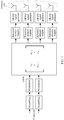
- scrambling processing, modulation processing, processing of an SFBC encoder, processing of a resource element mapper, and processing of an orthogonal frequency division multiplexing (Orthogonal Frequency Division Multiplexing, OFDM) signal generator are sequentially performed on a to-be-sent signal, and finally, the data is sent by using antenna ports.
- OFDM Orthogonal Frequency Division Multiplexing
- Embodiments of the present invention provide a transmit diversity method and a device, so that diversity coding similar to space frequency block coding is combined with precoding, thereby increasing an antenna gain, further reducing a space loss, and improving data transmission reliability.
- a first aspect of the embodiments of the present invention provides a transmit diversity method, including:
- diversity coding similar to space frequency block coding is combined with precoding, so that an antenna gain can be increased, further a space loss can be reduced, and data transmission reliability can be improved.
- the first network device determines the diversity coding scheme as a first diversity coding scheme; and/or if the rank index information is a second preset rank 4, the first network device determines the diversity coding scheme as a second diversity coding scheme.
- the first possible implementation of the first aspect of the embodiments of the present invention provides two ranks and two diversity coding schemes, and different diversity coding schemes are determined based on different ranks.
- a specific process of continuing, by the first network device, to perform transmission processing on to-be-transmitted data based on the diversity coding scheme and the precoding matrix is:
- the second possible implementation of the first aspect of the embodiments of the present invention is a complete process of transmission processing.
- the diversity coding similar to the space frequency block coding is combined with the precoding, so that not only an SFBC diversity gain can be obtained, but also a precoding gain can be obtained, thereby increasing an antenna gain.
- M symb -1, and M symb represents a quantity of data symbols of the to-be-transmitted data
- X 2 k ,1 represents a data symbol to which first-layer data is mapped on a 2 k th subcarrier, and corresponds to a data symbol d (2 k ) of the first data
- X 2 k +1,2 represents a data symbol to which the first-layer data is
- the third possible implementation and the fourth possible implementation of the first aspect of the embodiments of the present invention are specific processing processes performed by using two diversity coding schemes, so that the SFBC diversity gain can be obtained.
- a fifth possible implementation of the first aspect of the embodiments of the present invention if d (2 k ) and d (2 k +2) are same data, and d (2 k +1) and d (2 k +3) are same data, repeated data exists in the second data, helping to improve the data transmission reliability; or if d (2 k ) and d (2 k +2) are different data, and d (2 k +1) and d (2 k +3) are different data, no repeated data exists in the second data, helping to improve the data transmission reliability.
- the sixth possible implementation of the first aspect of the embodiments of the present invention is a specific precoding processing process, to obtain the precoding gain.
- a second aspect of the embodiments of the present invention provides another transmit diversity method, including:
- the rank index information and the precoding matrix index information are sent to the first network device, so that the first network device determines the diversity coding scheme and the precoding matrix, and further, the first network device combines space frequency block coding with precoding.
- a specific process of sending, by the second network device, rank index information and precoding matrix index information to a first network device is:
- a third aspect of the embodiments of the present invention provides a first network device, including:
- the first network device provided in the third aspect of the embodiments of the present invention is configured to implement the transmit diversity method provided in the first aspect of the embodiments of the present invention, and details are not described herein again.
- a fourth aspect of the embodiments of the present invention provides a second network device, including:
- the second network device provided in the fourth aspect of the embodiments of the present invention is configured to implement the transmit diversity method provided in the second aspect of the embodiments of the present invention, and details are not described herein again.
- a fifth aspect of the embodiments of the present invention provides another first network device.
- the first network device includes a receiver, a transmitter, a memory, and a processor, where the memory stores a group of program code, and the processor is configured to invoke the program code stored in the memory, so that the first network device performs the transmit diversity method provided in Embodiment 1 of the present invention.
- a sixth aspect of the embodiments of the present invention provides another second network device.
- the second network device includes an input module, an output module, a memory, and a processor, where the memory stores a group of program code, and the processor is configured to invoke the program code stored in the memory, so that the second network device performs the transmit diversity method provided in Embodiment 2 of the present invention.
- a seventh aspect of the embodiments of the present invention provides a transmit diversity system, including the first network device provided in the third aspect of the embodiments of the present invention and the second network device provided in the fourth aspect, or the first network device provided in the fifth aspect of the embodiments of the present invention and the second network device provided in the sixth aspect.
- the second network device measures the channel state information based on the pilot signal, and sends the rank index information and the precoding matrix index information to the first network device.
- the first network device receives the rank index information and the precoding matrix information that are sent by the second network device, determines the diversity coding scheme based on the rank index information, determines the precoding matrix based on the precoding matrix index information, and performs transmission processing on the to-be-transmitted data based on the determined diversity coding scheme and the precoding matrix index information. Therefore, the diversity coding similar to the space frequency block coding is combined with the precoding, so that the antenna gain is increased, further, the space loss is reduced, and the data transmission reliability is improved.
- the embodiments of the present invention provide a transmit diversity method, a device, and a system that may be applied to a scenario in which data is transmitted in a high-frequency environment, for example, a scenario in which a second network device measures channel state information based on a pilot signal, and sends rank index information and precoding matrix index information to a first network device based on the channel state information; the first network device receives the rank index information and the precoding matrix index information that are sent by the second network device based on the channel state information; the first network device determines a diversity coding scheme based on the rank index information; the first network device determines a precoding matrix based on the precoding matrix index information; and the first network device performs transmit diversity processing on to-be-transmitted data based on the diversity coding scheme and the precoding matrix.
- space frequency block coding is improved, precoding is added, and diversity coding similar to the space frequency block coding is combined with the precoding, so that both an SFBC diversity gain and a precoding gain can be obtained, thereby increasing an antenna gain, further reducing a space loss, and improving data transmission reliability.
- the first network device in the embodiments of the present invention is a part or all of a base station, and the base station may be a base station in any network scenario.
- the second network device in the embodiments of the present invention is user equipment, and may include but is not limited to an electronic device having a communication function, for example, a mobile phone, a tablet computer, a hand ring, a watch, or an intelligent wearable device.
- a precondition of implementing the embodiments of the present invention is that the base station configures a new transmission mode for the second network device, namely, a transmission mode in which the diversity coding similar to the space frequency block coding is combined with the precoding.
- the transmit diversity system in the embodiments of the present invention includes a first network device and a second network device.
- One second network device in the system is described in the embodiments of the present invention, and an implementation of the other second network device is the same as that of the second network device in the embodiments of the present invention.
- the second network device in the embodiments of the present invention is located in network coverage of a base station corresponding to the first network device.
- a communication process of the second network device is controlled by the base station.
- the base station may allocate a transmission resource, a channel, and the like to the second network device, and send information to the second network device by using an antenna port of the base station.
- FIG. 2 is a schematic flowchart of a transmit diversity method according to Embodiment 1 of the present invention. As shown in FIG. 2 , the method provided in Embodiment 1 of the present invention may include content of 101 to 106.
- a second network device measures channel state information based on a pilot signal.
- a first network device sends the pilot signal to the second network device by using an air interface between the first network device and the second network device, so that the second network device measures the channel state information based on the pilot signal, and sends rank index information and precoding matrix index information to the first network device.
- the pilot signal is a signal sent for the purpose of measurement or monitoring in a telecommunications network, and is transmitted by using a physical channel.
- the pilot signal may be sent by the first network device, or may be sent by a base station of the first network device.
- the pilot signal may be a channel state information-reference signal (Channel State Indication Reference Signal, CSI-RS), and the CSI-RS is a periodically sent pilot signal.
- CSI-RS Channel State Indication Reference Signal
- the second network device receives, by using the air interface between the first network device and the second network device, the pilot signal sent by the first network device, and measures the channel state information based on the pilot signal when receiving the pilot signal.
- the channel state information may include information such as a channel quality indicator (Channel Quality Indicator, CQI), a precoding matrix index (Precoding Matrix Index, PMI), and a rank index (Rank Index, RI).
- CQI Channel Quality Indicator
- PMI Precoding Matrix Index
- RI rank index
- the CQI is a standard of measuring communication quality of a radio channel.
- the CQI may be one value (or a plurality of values) capable of representing a channel measurement standard of a given channel.
- a high-value CQI may represent that a channel has high quality, and vice versa.
- the PMI is used to indicate a precoding matrix.
- Precoding is an adaptive technology of a multiple-antenna system.
- the second network device determines the PMI based on the channel state information, and further determines the precoding matrix based on the PMI.
- a set of codebook including several precoding matrices is stored in each of the first network device and the second network device. In this way, the second network device may select one precoding matrix based on an estimated channel matrix and a criterion, and send an index value of the precoding matrix and quantized channel state information to the first network device.
- the second network device re-measures the channel state information, determines a new PMI and a new precoding matrix, and sends the new PMI to the first network device.
- the first network device re-determines a precoding matrix based on the new PMI.
- RI represents a rank in an antenna matrix in a multiple-input multiple-output (Multiple-Input Multiple-Output, MIMO) system. If the RI is N, it represents N concurrent valid data streams. A data stream used for actual transmission in the MIMO system is referred to as a quantity of layers.
- the RI may represent relevancy between a plurality of transmission channels between the first network device and the second network device. If the RI is 1, it represents that the plurality of transmission channels are completely relevant, and transmitted signals possibly may interfere with each other. As a result, the second network device can hardly accurately receive the signals. If the RI is greater than 1, it represents that the plurality of channels are independent and irrelevant.
- the second network device may receive signals on different channels, and perform independent or joint decoding according to a precoding rule, thereby improving transmission reliability and increasing a channel capacity.
- the second network device sends rank index information and precoding matrix index information to the first network device based on the channel state information.
- the second network device extracts the rank index information and the precoding matrix index information in the measured channel state information, and sends the rank index information and the precoding matrix index information to the first network device by using the air interface between the second network device and the first network device.
- the second network device may perform sending to the first network device periodically or non-periodically. This depends on a specific case, and a specific sending period is not limited herein.
- the second network device sends all measured channel state information to the first network device, and in this embodiment of the present invention, the second network device needs to send only the rank index information and the precoding matrix index information in the channel state information.
- the rank index information is in this embodiment of the present invention is a first preset rank 2 or a second preset rank 4.
- current rank index information not only may be the first preset rank 2 or the second preset rank 4, but also may be another rank, and as a result, a plurality of ranks need to be traversed before a rank to be sent to the first network device is determined. In this embodiment of the present invention, there are only two ranks, thereby reducing an operation time to some extent.
- the second network device selects a precoding matrix from a preset precoding codebook based on the channel state information, and the second network device determines the precoding matrix index information based on the precoding matrix, and sends the precoding matrix index information to the first network device.
- the preset precoding codebook is stored in each of the second network device and the first network device. The second network device determines the precoding matrix index information based on the preset precoding codebook, and the first network device determines, based on the preset precoding codebook, a precoding codebook corresponding to the precoding matrix index information.
- the first network device receives the rank index information and the precoding matrix index information that are sent by the second network device based on the channel state information.
- the first network device receives, by using the air interface between the second network device and the first network device, the rank index information and the precoding matrix index information that are sent by the second network device based on the channel state information.
- the first network device determines a diversity coding scheme based on the rank index information.
- the first network device determines whether the received rank index information is the first preset rank 2 or the second preset rank 4, and determines the diversity coding scheme based on a determining result.
- the diversity coding scheme is similar to SFBC coding shown in FIG. 1 .
- the diversity coding scheme is two space frequency block coding matrices in FIG. 3 .
- Data symbols in the first row of the first matrix are x 2 k and x 2 k +1
- data symbols in the first row of the second matrix are x 2 k +2 and x 2 k +3 .
- x 2 k and x 2 k +2 may represent data symbols of same data, or may represent different data symbols of different data.
- x 2 k +1 and x 2 k +3 may represent data symbols of same data, or may represent different data symbols of different data.
- the first network device controls the switch to be disconnected, so that a quantity of layers of data flowing into the space frequency block coding matrices is two.
- the rank index information is the second preset rank 4
- the first network device controls the switch to be connected, so that a quantity of layers of data flowing into the space frequency block coding matrices is four. It may be understood that the first network device controls, based on the rank index information, the switch to be disconnected or connected, to further determine the diversity coding scheme.
- the first network device determines the diversity coding scheme as a first diversity coding scheme, and the first diversity coding scheme is a diversity coding scheme for two layers of data.
- the first network device determines the transmit diversity manner as a second diversity coding scheme, and the second diversity coding scheme is a diversity coding scheme for four layers of data.
- the first network device determines a precoding matrix based on the precoding matrix index information.
- the first network device determines the precoding matrix based on the precoding matrix index information sent by the second network device, in other words, determines the precoding matrix used for precoding in FIG. 3 .
- Precoding may be classified into linear precoding and non-linear precoding.
- linear precoding a side receiving channel state information can perform decoding only by using some linear detection means.
- the linear detection means mainly include linear zero forcing (including a beamforming method and the like), channel inversion, and the like.
- Design of non-linear precoding is complex. Common non-linear precoding is dirty-paper coding, and generally, N relevant non-linear equations need to be processed.
- the linear precoding operation may be classified into two categories of precoding schemes based on locations of obtaining precoding matrices thereof: a non-codebook-based precoding operation and a codebook-based precoding operation.
- a precoding matrix is obtained on a base station side.
- the base station side calculates a precoding matrix by using predicted channel state information CSI.
- a common precoding matrix calculation method includes singular value decomposition, uniform channel decomposition, and the like.
- a dedicated pilot needs to be used. In other words, a data symbol and a pilot symbol are used together for a precoding operation. In this way, a user side can obtain, only through channel estimation, an equivalent channel after precoding, facilitating data demodulation.
- a precoding matrix is obtained on a user side.
- the second network device selects a precoding matrix from a predetermined precoding codebook by using measured channel state information, and sends a sequence number (PMI) of the selected precoding matrix to a base station.
- the precoding matrix codebook is constructed in a plurality of manners, for example, a codebook based on antenna selection, a codebook based on an adaptive array transmit mode, a codebook based on discrete Fourier transform, or a random codebook.
- the precoding matrix may be selected from the predetermined precoding matrix codebook based on performance indicator-based selection and quantization-based selection.
- the first network device selects the precoding matrix from the preset precoding codebook based on the precoding index information, to determine the precoding matrix.
- the first network device performs transmission processing on to-be-transmitted data based on the diversity coding scheme and the precoding matrix.
- the first network device performs transmission processing on the to-be-transmitted data based on the determined diversity coding scheme and precoding matrix.
- the first network device performs coding, scrambling, and modulation processing on the to-be-transmitted data, to obtain first data.
- Data symbols of the to-be-transmitted data are represented as a (0),..., a ( M symb -1), in other words, code words in FIG. 3 .
- the code words are coded, and then, scrambling and modulation processing in FIG. 3 are performed on the code words, to obtain the first data.
- Data symbols of the first data are represented as d (0),..., d ( M symb -1), and M symb represents a quantity of data symbols of the to-be-transmitted data.
- M symb is a quantity of data symbols of the code word, to be specific, a quantity of the code words included in the to-be-transmitted data.
- M symb is a sum of quantities of data symbols of the two code words, and includes a quantity M symb (0) of data symbols of the first code word and a quantity M symb (1) of data symbols of the second code word.
- a specific coding scheme and a specific scrambling manner are not limited in this embodiment of the present invention.
- modulation schemes are different.
- a modulation scheme is quadrature phase shift keying (Quadrature Phase Shift Keying, QPSK), 16 quadrature amplitude modulation (Quadrature Amplitude Modulation, QAM), or 64 QAM.
- QPSK Quadrature Phase Shift Keying
- QAM Quadrature Amplitude Modulation
- Each code word of the to-be-transmitted data is coded, and the coded data is scrambled, so that the data is transmitted on one physical channel.
- the scrambled data is modulated, to generate complex modulation data symbols.
- the first network device processes the first data based on the diversity coding scheme, to obtain second data.
- the complex modulation data symbols are mapped to one or more transport layers. If the diversity coding scheme is determined as the first diversity coding scheme, the first network device processes the first data by using the first diversity coding scheme, to obtain the second data.
- X 2 k ,1 represents a data symbol to which first-layer data is mapped on a 2 k th subcarrier, and corresponds to a data symbol d (2 k ) of the first data
- X 2 k +1,1 represents a data symbol to which the first-layer data is mapped on a 2 k +1 th subcarrier, and corresponds to a data symbol -( d (2 k +1))* of the first data
- X 2 k ,2 represents a data symbol to which second-layer data is mapped on the 2 k th subcarrier, and corresponds to a data symbol d (2 k +1) of the first data
- X 2 k ,1 represents a data symbol to which first-layer data is mapped on a 2 k th subcarrier, and corresponds to a data symbol d (2 k ) of the first data
- X 2 k +1,1 represents a data symbol to which the first-layer data is mapped on a 2 k +1 th subcarrier, and corresponds to a data symbol d (2 k +1) of the first data
- X 2 k ,2 represents a data symbol to which second-layer data is mapped on the 2 k th subcarrier, and corresponds to a data symbol -( d (2 k +1))* of the first data
- X 2 k ,1 represents a data symbol to which first-layer data is mapped on a 2 k th subcarrier, and corresponds to a data symbol d (2 k +1) of the first data
- X 2k +1,1 represents a data symbol to which the first-layer data is mapped on a 2 k +1 th subcarrier, and corresponds to a data symbol -( d (2 k ))* of the first data
- X 2 k ,2 represents a data symbol to which second-layer data is mapped on the 2 k th subcarrier, and corresponds to a data symbol d (2 k ) of the first data
- X 2 k ,1 represents a data symbol to which first-layer data is mapped on a 2 k th subcarrier, and corresponds to a data symbol d (2 k +1) of the first data
- X 2 k +1,1 represents a data symbol to which the first-layer data is mapped on a 2 k +1 th subcarrier, and corresponds to a data symbol d (2 k ) of the first data
- X 2 k ,2 represents a data symbol to which second-layer data is mapped on the 2 k th subcarrier, and corresponds to a data symbol -( d (2 k ))* of the first data
- X 2 k ,1 represents a data symbol to which first-layer data is mapped on a 2 k th subcarrier, and corresponds to a data symbol d (2 k ) of the first data
- X 2 k +1,2 represents a data symbol to which the first-layer data is mapped on a 2 k +1 th subcarrier, and corresponds to a data symbol d (2 k +1) of
- the first network device performs precoding processing on the second data based on the determined precoding matrix, to obtain third data, in other words, performs precoding processing on each layer of complex modulation data symbols, to obtain the third data.
- a quantity of rows of the precoding matrix is a quantity of antenna ports, and a quantity of columns is a rank.
- the first network device After performing precoding processing, the first network device performs resource block mapping and OFDM signal generation processing on the third data, and sends the third data.
- Resource block mapping processing is performed by a resource element mapper in FIG. 3
- OFDM signal generation processing is performed by an OFDM signal generator in FIG. 3 .
- the resource element mapper maps each layer of complex modulation data symbols on which precoding is performed to a resource element ( k,l ) in a physical resource block.
- the OFDM signal generator modulates, into time-domain OFDM data symbols, each layer of complex modulation data symbols processed by the resource element mapper.
- the first network device sends, by using antenna ports in FIG. 3 , the data symbols processed by the OFDM signal generator.
- the first network device may send the processed data to the second network device, or may send the processed data to another network device.
- the second network device performs OFDM demodulation on the data when receiving the data that is sent by the first network device by using the antenna ports.
- the second network device measures the channel state information based on the pilot signal, and sends the rank index information and the precoding matrix index information to the first network device based on the channel state information.
- the first network device receives the rank index information and the precoding matrix index information that are sent by the second network device based on the channel state information, determines the diversity coding scheme based on the rank index information, determines the precoding matrix based on the precoding matrix index information, and performs transmission processing on the to-be-transmitted data based on the determined diversity coding scheme and precoding matrix. Therefore, diversity coding similar to space frequency block coding is combined with precoding, so that an antenna gain is increased, further a space loss is reduced, and the data transmission reliability is improved.
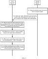
- FIG. 5 is a schematic flowchart of a transmit diversity method according to Embodiment 2 of the present invention. As shown in FIG. 5 , the method provided in Embodiment 2 of the present invention may include content of 201 to 204.
- a first network device receives rank index information and precoding matrix index information that are sent by a second network device.
- the first network device before the first network device receives the rank index information and the precoding matrix index information that are sent by the second network device, the first network device sends a pilot signal to the second network device by using an air interface between the first network device and the second network device, so that the second network device measures channel state information based on the pilot signal, and sends the rank index information and the precoding matrix index information to the first network device.
- the first network device may send different pilot signals to the plurality of network devices.
- the first network device receives, by using the air interface between the second network device and the first network device, the rank index information and the precoding matrix index information that are sent by the second network device based on the channel state information.
- the first network device determines a diversity coding scheme based on the rank index information.
- the first network device determines whether the received rank index information is the first preset rank 2 or the second preset rank 4, and determines the diversity coding scheme based on a determining result.
- the diversity coding scheme is similar to SFBC coding shown in FIG. 1 .
- the diversity coding scheme is two space frequency block coding matrices in FIG. 3 .
- Data symbols in the first row of the first matrix are x 2 k and x 2 k +1
- data symbols in the first row of the second matrix are x 2 k +2 and x 2 k +3 .
- x 2 k and x 2 k +2 may represent data symbols of same data, or may represent different data symbols of different data.
- x 2 k +1 and x 2 k +3 may represent data symbols of same data, or may represent different data symbols of different data.
- the first network device controls the switch to be disconnected, so that a quantity of layers of data flowing into the space frequency block coding matrices is two.
- the rank index information is the second preset rank 4
- the first network device controls the switch to be connected, so that a quantity of layers of data flowing into the space frequency block coding matrices is four. It may be understood that the first network device controls, based on the rank index information, the switch to be disconnected or connected, to further determine the diversity coding scheme.
- the first network device determines the diversity coding scheme as a first diversity coding scheme, and the first diversity coding scheme is a diversity coding scheme for two layers of data.
- the first network device determines the transmit diversity manner as a second diversity coding scheme, and the second diversity coding scheme is a diversity coding scheme for four layers of data.
- the first network device determines a precoding matrix based on the precoding matrix index information.
- the first network device determines the precoding matrix based on the precoding matrix index information sent by the second network device, in other words, determines the precoding matrix used for precoding in FIG. 3 .
- Precoding may be classified into linear precoding and non-linear precoding.
- linear precoding a side receiving channel state information can perform decoding only by using some linear detection means.
- the linear detection means mainly include linear zero forcing (including a beamforming method and the like), channel inversion, and the like.
- Design of non-linear precoding is complex. Common non-linear precoding is dirty-paper coding, and generally, N relevant non-linear equations need to be processed.
- the linear precoding operation may be classified into two categories of precoding schemes based on locations of obtaining precoding matrices thereof: a non-codebook-based precoding operation and a codebook-based precoding operation.
- a precoding matrix is obtained on a base station side.
- the base station side calculates a precoding matrix by using predicted channel state information CSI.
- a common precoding matrix calculation method includes singular value decomposition, uniform channel decomposition, and the like.
- a dedicated pilot needs to be used. In other words, a data symbol and a pilot symbol are used together for a precoding operation. In this way, a user side can obtain, only through channel estimation, an equivalent channel after precoding, facilitating data demodulation.
- a precoding matrix is obtained on a user side.
- the second network device selects a precoding matrix from a predetermined precoding codebook by using measured channel state information, and sends a sequence number (PMI) of the selected precoding matrix to a base station.
- the precoding matrix codebook is constructed in a plurality of manners, for example, a codebook based on antenna selection, a codebook based on an adaptive array transmit mode, a codebook based on discrete Fourier transform, or a random codebook.
- the precoding matrix may be selected from the predetermined precoding matrix codebook based on performance indicator-based selection and quantization-based selection.
- the first network device selects the precoding matrix from the preset precoding codebook based on the precoding index information, to determine the precoding matrix.
- the first network device performs transmission processing on to-be-transmitted data based on the diversity coding scheme and the precoding matrix.
- the first network device performs transmission processing on the to-be-transmitted data based on the determined diversity coding scheme and precoding matrix.
- the first network device performs coding, scrambling, and modulation processing on the to-be-transmitted data, to obtain first data.
- Data symbols of the to-be-transmitted data are represented as a (0),..., a ( M symb -1), in other words, code words in FIG. 3 .
- the code words are coded, and then, scrambling and modulation processing in FIG. 3 are performed on the code words, to obtain the first data.
- Data symbols of the first data are represented as d (0),..., d ( M symb -1) , and M symb represents a quantity of data symbols of the to-be-transmitted data.
- M symb is a quantity of data symbols of the code word, to be specific, a quantity of the code words included in the to-be-transmitted data.
- M symb is a sum of quantities of data symbols of the two code words, and includes a quantity M symb of data symbols of the first code word and a quantity M symb of data symbols of the second code word.
- a specific coding scheme and a specific scrambling manner are not limited in this embodiment of the present invention.
- modulation schemes are different.
- a modulation scheme is quadrature phase shift keying (Quadrature Phase Shift Keying, QPSK), 16 quadrature amplitude modulation (Quadrature Amplitude Modulation, QAM), or 64 QAM.
- QPSK Quadrature Phase Shift Keying
- QAM Quadrature Amplitude Modulation
- Each code word of the to-be-transmitted data is coded, and the coded data is scrambled, so that the data is transmitted on one physical channel.
- the scrambled data is modulated, to generate complex modulation data symbols.
- the first network device processes the first data based on the determined diversity coding scheme, to obtain second data.
- X 2 k ,1 represents a data symbol to which first-layer data is mapped on a 2 k th subcarrier, and corresponds to a data symbol d (2 k ) of the first data
- X 2 k +1,1 represents a data symbol to which the first-layer data is mapped on a 2 k +1 th subcarrier, and corresponds to a data symbol -( d (2 k +1))* of the first data
- X 2 k ,2 represents a data symbol to which second-layer data is mapped on the 2 k th subcarrier, and corresponds to a data symbol d (2 k +1) of the first data
- X 2 k ,1 represents a data symbol to which first-layer data is mapped on a 2 k th subcarrier, and corresponds to a data symbol d (2 k ) of the first data
- X 2 k +1,1 represents a data symbol to which the first-layer data is mapped on a 2 k +1 th subcarrier, and corresponds to a data symbol d (2 k +1) of the first data
- X 2 k ,2 represents a data symbol to which second-layer data is mapped on the 2 k th subcarrier, and corresponds to a data symbol -( d (2 k +1))* of the first data
- X 2 k ,1 represents a data symbol to which first-layer data is mapped on a 2 k th subcarrier, and corresponds to a data symbol d (2 k +1) of the first data
- X 2 k +1,1 represents a data symbol to which the first-layer data is mapped on a 2 k +1 th subcarrier, and corresponds to a data symbol -( d (2 k ))* of the first data
- X 2 k ,2 represents a data symbol to which second-layer data is mapped on the 2 k th subcarrier, and corresponds to a data symbol d (2 k ) of the first data
- X 2 k ,1 represents a data symbol to which first-layer data is mapped on a 2 k th subcarrier, and corresponds to a data symbol d (2 k +1) of the first data
- X 2 k +1,1 represents a data symbol to which the first-layer data is mapped on a 2 k +1 th subcarrier, and corresponds to a data symbol d (2 k ) of the first data
- X 2 k ,2 represents a data symbol to which second-layer data is mapped on the 2 k th subcarrier, and corresponds to a data symbol -( d (2 k ))* of the first data
- X 2 k ,1 represents a data symbol to which first-layer data is mapped on a 2 k th subcarrier, and corresponds to a data symbol d (2 k ) of the first data
- X 2 k +1,2 represents a data symbol to which the first-layer data is mapped on a 2 k +1 th subcarrier, and corresponds to a data symbol d (2 k +1) of
- the first network device performs precoding processing on the second data based on the determined precoding matrix, to obtain third data, in other words, performs precoding processing on each layer of complex modulation data symbols, to obtain the third data.
- a quantity of rows of the precoding matrix is a quantity of antenna ports, and a quantity of columns is a rank.
- the first network device After performing precoding processing, the first network device performs resource block mapping and OFDM signal generation processing on the third data, and sends the third data.
- Resource block mapping processing is performed by a resource element mapper in FIG. 3
- OFDM signal generation processing is performed by an OFDM signal generator in FIG. 3 .
- the resource element mapper maps each layer of complex modulation data symbols on which precoding is performed to a resource element ( k , l ) in a physical resource block.
- the OFDM signal generator modulates, into time-domain OFDM data symbols, each layer of complex modulation data symbols processed by the resource element mapper.
- the first network device sends, by using antenna ports in FIG. 3 , the data symbols processed by the OFDM signal generator.
- the first network device may send the processed data to the second network device, or may send the processed data to another network device.
- the second network device performs OFDM demodulation on the data when receiving the data that is sent by the first network device by using the antenna ports.
- the first network receives the rank index information and the precoding matrix index information that are sent by the second network device, determines the diversity coding scheme based on the rank index information, determines the precoding matrix based on the precoding matrix index information, and performs transmission processing on the to-be-transmitted data based on the determined diversity coding scheme and precoding matrix. Therefore, the first network device combines diversity coding similar to space frequency block coding with precoding, so that not only an SFBC diversity gain can be obtained, but also a precoding gain can be obtained, thereby increasing an antenna gain, further, reducing a space loss, and improving the data transmission reliability
- FIG. 6 is a schematic flowchart of a transmit diversity method according to Embodiment 3 of the present invention. As shown in FIG. 6 , the method provided in Embodiment 3 of the present invention may include content of 301 and 302.
- a second network device measures channel state information based on a pilot signal.
- the second network device receives, by using an air interface between a first network device and the second network device, the pilot signal sent by the first network device, and measures the channel state information based on the pilot signal when receiving the pilot signal.
- the second network device sends rank index information and precoding matrix index information to a first network device based on the channel state information.
- the second network device extracts the rank index information and the precoding matrix index information in the measured channel state information, and sends the rank index information and the precoding matrix index information to the first network device by using the air interface between the second network device and the first network device.
- the second network device may perform sending to the first network device periodically or non-periodically. This depends on a specific case, and a specific sending period is not limited herein.
- the second network device sends all measured channel state information to the first network device, and in this embodiment of the present invention, the second network device needs to send only the rank index information and the precoding matrix index information in the channel state information.
- the rank index information is in this embodiment of the present invention is a first preset rank 2 or a second preset rank 4.
- current rank index information not only may be the first preset rank 2 or the second preset rank 4, but also may be another rank, and as a result, a plurality of ranks need to be traversed before a rank to be sent to the first network device is determined. In this embodiment of the present invention, there are only two ranks, thereby reducing an operation time to some extent.
- the second network device selects a precoding matrix from a preset precoding codebook based on the channel state information, and the second network device determines the precoding matrix index information based on the precoding matrix, and sends the precoding matrix index information to the first network device.
- the preset precoding codebook is stored in each of the second network device and the first network device. The second network device determines the precoding matrix index information based on the preset precoding codebook, and the first network device determines, based on the preset precoding codebook, a precoding codebook corresponding to the precoding matrix index information.
- the first network device determines a diversity coding scheme based on the rank index information sent by the second network device, determines the precoding matrix based on the precoding matrix index information, and further performs transmission processing on to-be-transmitted data based on the determined diversity coding scheme and precoding matrix. For a specific processing process, refer to FIG. 3 .
- the second network device may receive the processed data sent by the first network device. Because OFDM modulation is performed on the data on which transmission processing is performed, the second network device performs OFDM demodulation processing on the processed data when receiving the processed data sent by the first network device.
- the second network device receives the pilot signal sent by the first network device, measures the channel state information based on the pilot signal, and sends the rank index information and the precoding matrix index information to the first network device based on the channel state information, so that the first network device determines the diversity coding scheme and the precoding matrix, and the first network device combines space frequency block coding with precoding.
- FIG. 6 is a schematic structural diagram of a first network device according to an embodiment of the present invention.
- the first network device 60 includes an information receiving unit 601, a manner determining unit 602, a matrix determining unit 603, and a transmission processing unit 604.
- the information receiving unit 601 is configured to receive rank index information and precoding matrix index information that are sent by a second network device.
- the manner determining unit 602 is configured to determine a diversity coding scheme based on the rank index information.
- the matrix determining unit 603 is configured to determine a precoding matrix based on the precoding matrix index information.
- the data processing unit 604 is configured to perform transmission processing on to-be-transmitted data based on the diversity coding scheme and the precoding matrix.
- the first network device shown in FIG. 6 is configured to implement the embodiment shown in FIG. 4 .
- a basic idea and a beneficial effect of the first network device are the same as those of FIG. 4 , and details are not described herein again.
- FIG. 7 is a schematic structural diagram of a second network device according to an embodiment of the present invention.
- the second network device 70 includes an information measurement unit 701 and an information sending unit 702.
- the information measurement unit 701 is configured to measure channel state information based on a pilot signal.
- the information sending unit 702 is configured to send rank index information and precoding matrix index information to a first network device based on the channel state information, so that the first network device determines a diversity coding scheme based on the rank index information, determines a precoding matrix based on the precoding matrix index information, and performs transmission processing on to-be-transmitted data based on the diversity coding scheme and the precoding matrix.
- the first network device shown in FIG. 7 is configured to implement the embodiment shown in FIG. 5 .
- a basic idea and a beneficial effect of the first network device are the same as those of FIG. 5 , and details are not described herein again.
- the first network device shown in FIG. 6 and the second network device shown in FIG. 7 are combined, to implement the embodiment shown in FIG. 2 .
- FIG. 8 is a schematic structural diagram of another first network device according to an embodiment of the present invention.
- the first network device includes at least one processor 801, at least one communications bus 802, a receiver 803, a transmitter 804, and a memory 805.
- the communications bus 802 is configured to implement connection and communication between the components.
- the receiver 803 and the transmitter 804 are collectively referred to as a transceiver station.
- the transceiver station implements, under the control of the processor 801, control of a base station and switching between radio channels, to implement transmission and reception of a communication signal of user equipment, wireless transmission performed between mobile stations through an air interface, and a related control function.
- the processor 801 is responsible for management of all mobile communications interface, and is mainly responsible for radio channel allocation, release, and management.
- the processor 801 invokes program code stored in the memory 805, to perform a corresponding operation and implement a corresponding function.
- the processor 801 in this embodiment of the present invention is configured to control data transmission.
- the processor 801 includes a scrambling module, a modulation module, a diversity module, a precoding module, a resource block module, and an OFDM module, respectively corresponding to scrambling, modulation, two matrices, precoding, a resource element mapper, and an OFDM signal generator in FIG. 3 .
- the processor 801 is configured to implement the manner determining unit, the matrix determining unit, and the data processing unit in the embodiment shown in FIG. 6 . For a specific implementation process, refer to specific descriptions of the embodiment shown in FIG. 4 , and details are not described herein again.
- the receiver 803 is configured to: implement the information receiving unit in the embodiment shown in FIG. 6 , and receive rank index information and precoding matrix index information that are sent by a second network device.
- the transmitter is configured to transmit data processed by the processor 801 to user equipment in coverage of the first network device by using an antenna port, where the user equipment includes the second network device.
- the antenna port of the first network device is not marked in FIG. 8 .
- FIG. 9 is a schematic structural diagram of another second network device according to an embodiment of the present invention.
- the second network device includes at least one processor 901 such as a CPU, at least one communications bus 902, an input device 903, an output device 904, a memory 905, a power supply module 906, and a wireless communications module 907.
- the communications bus 902 is configured to implement connection and communication between the components.
- the input device 903 is configured to receive an audio or video signal, and is further configured to: receive an input command of a user, and generate key input data based on the input command, to control various operations of the second network device.
- the output device 904 is constructed to provide an output signal (for example, an audio signal, a video signal, an alarm signal, or a vibration signal) in a visual, audio, and/or tactile manner.
- the output device 904 may include a display unit, an audio output module, an alarm unit, and the like, and these are not marked in FIG. 9 .
- the power module 906 receives, under the control of the processor 901, external power or internal power, and supply needed power to a device, a module, the memory 905, the processor 901, and the like on the communications bus 902.
- the memory 905 may include at least one type of storage medium.
- the storage medium includes a flash memory, a hard disk, a multimedia card, a card memory (for example, an SD memory or a DX memory), a random access memory (RAM), a static random access memory (SRAM), a read-only memory (ROM), an electrically erasable programmable read-only memory (EEPROM), a programmable read-only memory (PROM), a magnetic memory, a magnetic disk, an optical disc, and the like.
- the processor 901 usually controls an overall operation of the second network device. For example, the processor 901 performs controlling and processing related to a voice call, data communication, a video call, and the like.
- the processor 901 is configured to: implement the information measurement unit in the embodiment shown in FIG. 7 , and measure channel state information based on a pilot signal.
- the wireless communications module 907 is configured to send a radio signal to at least one of a base station (for example, an access point, a NodeB, and the like), an external terminal, and a server, and/or an apparatus receiving a radio signal from the wireless communications module.
- the radio signal may be a voice call signal, a video call signal, or various types of data sent and/or received based on a text and/or multimedia message.
- the wireless communications unit 907 is configured to: implement the information sending unit in the embodiment shown in FIG. 7 , send rank index information and precoding matrix index information to a first network device, so that the first network device determines a diversity coding scheme based on the rank index information, determines a precoding matrix based on the precoding matrix index information, and performs transmission processing on to-be-transmitted data based on the diversity coding scheme and the precoding matrix.
- the wireless communications module 907 further includes an air interface, and this is not marked in FIG. 9 .
- the air interface is configured to perform communication between the second network device and another user equipment or the first network device.
- An embodiment of the present invention further provides a transmit diversity system, including the first network device shown in FIG. 6 and the second network device shown in FIG. 7 , or including the first network device shown in FIG. 8 and the second network device shown in FIG. 9 .
- a sequence of the steps of the method in the embodiments of the present invention may be adjusted, and certain steps may also be merged or removed according to an actual need.
- the present invention may be implemented by hardware, firmware or a combination thereof.
- the foregoing functions may be stored in a computer-readable medium or transmitted as one or more instructions or code in the computer-readable medium.
- the computer-readable medium includes a computer storage medium and a communications medium, where the communications medium includes any medium that enables a computer program to be transmitted from one place to another.
- the storage medium may be any available medium accessible to a computer.
- the computer readable medium may include a random access memory (Random Access Memory, RAM), a read-only memory (Read-Only Memory, ROM), an electrically erasable programmable read-only memory (Electrically Erasable Programmable Read-Only Memory, EEPROM), a compact disc read-only memory (Compact Disc Read-Only Memory, CD-ROM) or other optical disk storage, a disk storage medium or other disk storage, or any other medium that can be used to carry or store expected program code in a command or data structure form and can be accessed by a computer.
- any connection may be appropriately defined as a computer-readable medium.
- the coaxial cable, optical fiber/cable, twisted pair, DSL or wireless technologies such as infrared ray, radio and microwave
- the coaxial cable, optical fiber/cable, twisted pair, DSL or wireless technologies such as infrared ray, radio and microwave are included in fixation of a medium to which they belong.
- a disk (Disk) and disc (disc) used by the present invention includes a compact disc CD, a laser disc, an optical disc, a digital versatile disc (DVD), a floppy disk and a Blu-ray disc, where the disk generally copies data by a magnetic means, and the disc copies data optically by a laser means.
- DVD digital versatile disc
- a floppy disk and a Blu-ray disc, where the disk generally copies data by a magnetic means, and the disc copies data optically by a laser means.
- the foregoing combination should also be included in the protection scope of the computer-readable medium.
Landscapes
- Engineering & Computer Science (AREA)
- Signal Processing (AREA)
- Computer Networks & Wireless Communication (AREA)
- Radio Transmission System (AREA)
- Mobile Radio Communication Systems (AREA)
Abstract
Description
- The present invention relates to the field of communications technologies, and in particular, to a transmit diversity method, a device, and a system.
- Communication between base stations includes backhaul (back haul) link communication and fronthaul (front haul) link communication. Backhaul refers to a network from a base station controller to a serving gateway or a mobility management entity, and fronthaul refers to a network from a baseband processing unit (Building Base band Unit, BBU) of an antenna to the base station controller. Backhaul and fronthaul impose very high requirements on reliability. For example, a packet error rate (Packet Error Rate, PER) of backhaul needs to be 10-6, and a packet error rate of fronthaul needs to be 10-8. In addition, the backhaul link communication and the fronthaul link communication are usually deployed in a high frequency, and a space loss of the high frequency is very large. Therefore, a higher requirement is imposed on reliability of transmission in a high-frequency environment.
- Currently, transmission reliability is improved mainly by using a diversity solution. A basic idea of diversity is: If a plurality of independently fading signals can be transmitted, from the perspective of statistics, fading of a combined signal is much lower than fading of each signal. Under the assumption of independent fading, when some signals fade deeply, fading of some other signals may be relatively slight, and a probability that signals deeply fade simultaneously is very low. Therefore, a probability that a combined signal deeply fades is greatly reduced. The diversity solution includes space time coding (Space Time Coding, STC), cyclic delay diversity (Cyclic Delay Diversity, CDD), antenna switching diversity, and the like. A diversity solution combining space frequency block coding (Space Frequency Block Code, SFBC) and frequency switched transmit diversity (Frequency Switch Transmit Diversity, FSTD) is often used in Long Term Evolution (Long Term Evolution, LTE). As shown in
FIG. 1, FIG. 1 shows an SFBC diversity solution in LTE. First, scrambling processing, modulation processing, processing of an SFBC encoder, processing of a resource element mapper, and processing of an orthogonal frequency division multiplexing (Orthogonal Frequency Division Multiplexing, OFDM) signal generator are sequentially performed on a to-be-sent signal, and finally, the data is sent by using antenna ports. For an SFBC encoder with two transmit antennas, assuming that data symbols flowing to the SFBC encoder are x 2k and x 2k+1, x 2k is transmitted on a first subcarrier onantenna 1, and x 2k+1 is transmitted on a second subcarrier, while -x 2k+1* is transmitted on a first subcarrier onantenna 2, and x 2k * is transmitted on a second subcarrier. ()* represents conjugate of a complex number. In the diversity solution, repeated data is sent in a frequency and space, to improve transmission reliability, thereby improving reliability of receiving information by user equipment. However, for a high-frequency environment having a very great space loss, an antenna gain of the diversity solution is relatively low, the space loss cannot be overcome, and as a result, transmission reliability is severely affected. - Embodiments of the present invention provide a transmit diversity method and a device, so that diversity coding similar to space frequency block coding is combined with precoding, thereby increasing an antenna gain, further reducing a space loss, and improving data transmission reliability.
- A first aspect of the embodiments of the present invention provides a transmit diversity method, including:
- receiving, by a first network device, rank index information and precoding matrix index information that are sent by a second network device;
- determining, by the first network device, a diversity coding scheme based on the rank index information;
- determining, by the first network device, a precoding matrix based on the precoding matrix index information; and
- performing, by the first network device, transmission processing on to-be-transmitted data based on the diversity coding scheme and the precoding matrix.
- In the first aspect of the embodiments of the present invention, diversity coding similar to space frequency block coding is combined with precoding, so that an antenna gain can be increased, further a space loss can be reduced, and data transmission reliability can be improved.
- Based on the first aspect of the embodiments of the present invention, in a first possible implementation of the first aspect of the embodiments of the present invention, if the rank index information is a
first preset rank 2, the first network device determines the diversity coding scheme as a first diversity coding scheme; and/or if the rank index information is a second preset rank 4, the first network device determines the diversity coding scheme as a second diversity coding scheme. - The first possible implementation of the first aspect of the embodiments of the present invention provides two ranks and two diversity coding schemes, and different diversity coding schemes are determined based on different ranks.
- Based on the first possible implementation of the first aspect of the embodiments of the present invention, in a second possible implementation of the first aspect of the embodiments of the present invention, a specific process of continuing, by the first network device, to perform transmission processing on to-be-transmitted data based on the diversity coding scheme and the precoding matrix is:
- performing, by the first network device, coding, scrambling, and modulation processing on the to-be-transmitted data, to obtain first data;
- processing, by the first network device, the first data based on the diversity coding scheme, to obtain second data;
- performing, by the first network device, precoding processing on the second data based on the precoding matrix, to obtain third data; and
- performing, by the first network device, resource block mapping and OFDM signal generation processing on the third data, and sending the third data.
- The second possible implementation of the first aspect of the embodiments of the present invention is a complete process of transmission processing. The diversity coding similar to the space frequency block coding is combined with the precoding, so that not only an SFBC diversity gain can be obtained, but also a precoding gain can be obtained, thereby increasing an antenna gain.
- Based on the second possible implementation of the first aspect of the embodiments of the present invention, in a third possible implementation of the first aspect of the embodiments of the present invention, if the diversity coding scheme is the first diversity coding scheme, the first network device processes the first data by using the first diversity coding scheme, to obtain the second data, where data symbols of the first data are d(2k), 2k=0,1,...,Msymb -1, and Msymb represents a quantity of data symbols of the to-be-transmitted data, where
the first diversity coding scheme is:

the first diversity coding scheme is:

- Based on the second possible implementation of the first aspect of the embodiments of the present invention, in a fourth possible implementation of the first aspect of the embodiments of the present invention, if the diversity coding scheme is the second diversity coding scheme, the first network device processes the first data by using the second diversity coding scheme, to obtain the second data, where data symbols of the first data are d(2k),2k=0,1,...Msymb -1, and Msymb represents a quantity of data symbols of the to-be-transmitted data, where
the second diversity coding scheme is:


- The third possible implementation and the fourth possible implementation of the first aspect of the embodiments of the present invention are specific processing processes performed by using two diversity coding schemes, so that the SFBC diversity gain can be obtained.
- Based on the fourth possible implementation of the first aspect of the embodiments of the present invention, in a fifth possible implementation of the first aspect of the embodiments of the present invention, if d(2k) and d(2k+2) are same data, and d(2k+1) and d(2k+3) are same data, repeated data exists in the second data, helping to improve the data transmission reliability; or if d(2k) and d(2k+2) are different data, and d(2k+1) and d(2k+3) are different data, no repeated data exists in the second data, helping to improve the data transmission reliability.
- Based on the third to the fifth possible implementations of the first aspect of the embodiments of the present invention, in a sixth possible implementation of the first aspect of the embodiments of the present invention, the first network device performs precoding processing on the second data in a precoding scheme based on the precoding matrix, to obtain the third data, where
the precoding scheme is Y = WX , where W is the precoding matrix, X is the data symbol of the second data, and Y is a data symbol of the third data. - The sixth possible implementation of the first aspect of the embodiments of the present invention is a specific precoding processing process, to obtain the precoding gain.
- A second aspect of the embodiments of the present invention provides another transmit diversity method, including:
- measuring, by a second network device, channel state information based on a pilot signal; and
- sending, by the second network device, rank index information and precoding matrix index information to a first network device based on the channel state information, so that the first network device determines a diversity coding scheme based on the rank index information, determines a precoding matrix based on the precoding matrix index information, and performs transmission processing on to-be-transmitted data based on the diversity coding scheme and the precoding matrix.
- In the second aspect of the embodiments of the present invention, the rank index information and the precoding matrix index information are sent to the first network device, so that the first network device determines the diversity coding scheme and the precoding matrix, and further, the first network device combines space frequency block coding with precoding.
- Based on the second aspect of the embodiments of the present invention, in a first possible implementation of the second aspect of the embodiments of the present invention, a specific process of sending, by the second network device, rank index information and precoding matrix index information to a first network device is:
- sending, by the second network device, the rank index information to the first network device based on the channel state information;
- selecting, by the second network device, the precoding matrix from a preset precoding codebook based on the channel state information; and
- determining, by the second network device, the precoding matrix index information based on the precoding matrix, and sending the precoding matrix index information to the first network device.
- A third aspect of the embodiments of the present invention provides a first network device, including:
- an information receiving unit, configured to receive rank index information and precoding matrix index information that are sent by a second network device;
- a manner determining unit, configured to determine a diversity coding scheme based on the rank index information;
- a matrix determining unit, configured to determine a precoding matrix based on the precoding matrix index information; and
- a transmission processing unit, configured to perform transmission processing on to-be-transmitted data based on the diversity coding scheme and the precoding matrix.
- The first network device provided in the third aspect of the embodiments of the present invention is configured to implement the transmit diversity method provided in the first aspect of the embodiments of the present invention, and details are not described herein again.
- A fourth aspect of the embodiments of the present invention provides a second network device, including:
- an information measurement unit, configured to measure channel state information based on a pilot signal; and
- an information sending unit, configured to send rank index information and precoding matrix index information to a first network device based on the channel state information, so that the first network device determines a diversity coding scheme based on the rank index information, determines a precoding matrix based on the precoding matrix index information, and performs transmission processing on to-be-transmitted data based on the diversity coding scheme and the precoding matrix.
- The second network device provided in the fourth aspect of the embodiments of the present invention is configured to implement the transmit diversity method provided in the second aspect of the embodiments of the present invention, and details are not described herein again.
- A fifth aspect of the embodiments of the present invention provides another first network device. The first network device includes a receiver, a transmitter, a memory, and a processor, where the memory stores a group of program code, and the processor is configured to invoke the program code stored in the memory, so that the first network device performs the transmit diversity method provided in
Embodiment 1 of the present invention. - A sixth aspect of the embodiments of the present invention provides another second network device. The second network device includes an input module, an output module, a memory, and a processor, where the memory stores a group of program code, and the processor is configured to invoke the program code stored in the memory, so that the second network device performs the transmit diversity method provided in
Embodiment 2 of the present invention. - A seventh aspect of the embodiments of the present invention provides a transmit diversity system, including the first network device provided in the third aspect of the embodiments of the present invention and the second network device provided in the fourth aspect, or the first network device provided in the fifth aspect of the embodiments of the present invention and the second network device provided in the sixth aspect.
- In the embodiments of the present invention, the second network device measures the channel state information based on the pilot signal, and sends the rank index information and the precoding matrix index information to the first network device. The first network device receives the rank index information and the precoding matrix information that are sent by the second network device, determines the diversity coding scheme based on the rank index information, determines the precoding matrix based on the precoding matrix index information, and performs transmission processing on the to-be-transmitted data based on the determined diversity coding scheme and the precoding matrix index information. Therefore, the diversity coding similar to the space frequency block coding is combined with the precoding, so that the antenna gain is increased, further, the space loss is reduced, and the data transmission reliability is improved.
- To describe the technical solutions in the embodiments of the present invention or in the prior art more clearly, the following briefly describes the accompanying drawings required for describing the embodiments. Apparently, the accompanying drawings in the following description show merely some embodiments of the present invention, and a person of ordinary skill in the art may still derive other drawings from these accompanying drawings without creative efforts.
-
FIG. 1 is a schematic flowchart of a transmit diversity solution used in existing LTE; -
FIG. 2 is a schematic flowchart of a transmit diversity method according toEmbodiment 1 of the present invention; -
FIG. 3 is a schematic flowchart of a transmit diversity solution according to an embodiment of the present invention; -
FIG. 4 is a schematic flowchart of a transmit diversity method according toEmbodiment 2 of the present invention; -
FIG. 5 is a schematic flowchart of a transmit diversity method according toEmbodiment 3 of the present invention; -
FIG. 6 is a schematic structural diagram of a first network device according to an embodiment of the present invention; -
FIG. 7 is a schematic structural diagram of a second network device according to an embodiment of the present invention; -
FIG. 8 is a schematic structural diagram of another first network device according to an embodiment of the present invention; and -
FIG. 9 is a schematic structural diagram of another second network device according to an embodiment of the present invention. - The following clearly and completely describes the technical solutions in the embodiments of the present invention with reference to the accompanying drawings in the embodiments of the present invention. Apparently, the described embodiments are merely some but not all of the embodiments of the present invention. All other embodiments obtained by a person of ordinary skill in the art based on the embodiments of the present invention without creative efforts shall fall within the protection scope of the present invention.
- The embodiments of the present invention provide a transmit diversity method, a device, and a system that may be applied to a scenario in which data is transmitted in a high-frequency environment, for example, a scenario in which a second network device measures channel state information based on a pilot signal, and sends rank index information and precoding matrix index information to a first network device based on the channel state information; the first network device receives the rank index information and the precoding matrix index information that are sent by the second network device based on the channel state information; the first network device determines a diversity coding scheme based on the rank index information; the first network device determines a precoding matrix based on the precoding matrix index information; and the first network device performs transmit diversity processing on to-be-transmitted data based on the diversity coding scheme and the precoding matrix. Based on an existing diversity solution, in the embodiments of the present invention, space frequency block coding is improved, precoding is added, and diversity coding similar to the space frequency block coding is combined with the precoding, so that both an SFBC diversity gain and a precoding gain can be obtained, thereby increasing an antenna gain, further reducing a space loss, and improving data transmission reliability.
- The first network device in the embodiments of the present invention is a part or all of a base station, and the base station may be a base station in any network scenario. The second network device in the embodiments of the present invention is user equipment, and may include but is not limited to an electronic device having a communication function, for example, a mobile phone, a tablet computer, a hand ring, a watch, or an intelligent wearable device. A precondition of implementing the embodiments of the present invention is that the base station configures a new transmission mode for the second network device, namely, a transmission mode in which the diversity coding similar to the space frequency block coding is combined with the precoding.
- The transmit diversity system in the embodiments of the present invention includes a first network device and a second network device. In this system, there may be more than one second network device. One second network device in the system is described in the embodiments of the present invention, and an implementation of the other second network device is the same as that of the second network device in the embodiments of the present invention. The second network device in the embodiments of the present invention is located in network coverage of a base station corresponding to the first network device. A communication process of the second network device is controlled by the base station. The base station may allocate a transmission resource, a channel, and the like to the second network device, and send information to the second network device by using an antenna port of the base station.
- The following describes, in detail with reference to
FIG. 2 to FIG. 6 , the transmit diversity method provided in the embodiments of the present invention. - Referring to
FIG. 2, FIG. 2 is a schematic flowchart of a transmit diversity method according toEmbodiment 1 of the present invention. As shown inFIG. 2 , the method provided inEmbodiment 1 of the present invention may include content of 101 to 106. - 101. A second network device measures channel state information based on a pilot signal.
- Specifically, before the second network device measures the channel state information based on the pilot signal, a first network device sends the pilot signal to the second network device by using an air interface between the first network device and the second network device, so that the second network device measures the channel state information based on the pilot signal, and sends rank index information and precoding matrix index information to the first network device. The pilot signal is a signal sent for the purpose of measurement or monitoring in a telecommunications network, and is transmitted by using a physical channel. The pilot signal may be sent by the first network device, or may be sent by a base station of the first network device. The pilot signal may be a channel state information-reference signal (Channel State Indication Reference Signal, CSI-RS), and the CSI-RS is a periodically sent pilot signal.
- The second network device receives, by using the air interface between the first network device and the second network device, the pilot signal sent by the first network device, and measures the channel state information based on the pilot signal when receiving the pilot signal. The channel state information may include information such as a channel quality indicator (Channel Quality Indicator, CQI), a precoding matrix index (Precoding Matrix Index, PMI), and a rank index (Rank Index, RI).
- The CQI is a standard of measuring communication quality of a radio channel. The CQI may be one value (or a plurality of values) capable of representing a channel measurement standard of a given channel. Usually, a high-value CQI may represent that a channel has high quality, and vice versa.
- The PMI is used to indicate a precoding matrix. Precoding is an adaptive technology of a multiple-antenna system. In other words, the second network device determines the PMI based on the channel state information, and further determines the precoding matrix based on the PMI. A set of codebook including several precoding matrices is stored in each of the first network device and the second network device. In this way, the second network device may select one precoding matrix based on an estimated channel matrix and a criterion, and send an index value of the precoding matrix and quantized channel state information to the first network device. If the first network device sends the pilot signal to the second network device again after receiving the PMI sent by the second network device, the second network device re-measures the channel state information, determines a new PMI and a new precoding matrix, and sends the new PMI to the first network device. The first network device re-determines a precoding matrix based on the new PMI.
- RI represents a rank in an antenna matrix in a multiple-input multiple-output (Multiple-Input Multiple-Output, MIMO) system. If the RI is N, it represents N concurrent valid data streams. A data stream used for actual transmission in the MIMO system is referred to as a quantity of layers. The RI may represent relevancy between a plurality of transmission channels between the first network device and the second network device. If the RI is 1, it represents that the plurality of transmission channels are completely relevant, and transmitted signals possibly may interfere with each other. As a result, the second network device can hardly accurately receive the signals. If the RI is greater than 1, it represents that the plurality of channels are independent and irrelevant. The second network device may receive signals on different channels, and perform independent or joint decoding according to a precoding rule, thereby improving transmission reliability and increasing a channel capacity.
- 102. The second network device sends rank index information and precoding matrix index information to the first network device based on the channel state information.
- Specifically, the second network device extracts the rank index information and the precoding matrix index information in the measured channel state information, and sends the rank index information and the precoding matrix index information to the first network device by using the air interface between the second network device and the first network device. The second network device may perform sending to the first network device periodically or non-periodically. This depends on a specific case, and a specific sending period is not limited herein. Currently, the second network device sends all measured channel state information to the first network device, and in this embodiment of the present invention, the second network device needs to send only the rank index information and the precoding matrix index information in the channel state information. In addition, the rank index information is in this embodiment of the present invention is a first
preset rank 2 or a second preset rank 4. However, current rank index information not only may be the firstpreset rank 2 or the second preset rank 4, but also may be another rank, and as a result, a plurality of ranks need to be traversed before a rank to be sent to the first network device is determined. In this embodiment of the present invention, there are only two ranks, thereby reducing an operation time to some extent. - Optionally, the second network device selects a precoding matrix from a preset precoding codebook based on the channel state information, and the second network device determines the precoding matrix index information based on the precoding matrix, and sends the precoding matrix index information to the first network device. The preset precoding codebook is stored in each of the second network device and the first network device. The second network device determines the precoding matrix index information based on the preset precoding codebook, and the first network device determines, based on the preset precoding codebook, a precoding codebook corresponding to the precoding matrix index information.
- 103. The first network device receives the rank index information and the precoding matrix index information that are sent by the second network device based on the channel state information.
- Specifically, the first network device receives, by using the air interface between the second network device and the first network device, the rank index information and the precoding matrix index information that are sent by the second network device based on the channel state information.
- 104. The first network device determines a diversity coding scheme based on the rank index information.
- Specifically, because orthogonality between data paths on different MIMO channels is different, interference between data streams needs to be considered in an actual application. When a plurality of code words are transmitted by using a plurality of antennas, a quantity of data streams, in other words, a quantity of layers, that can be sent at the same time needs to be determined based on a rank of a space channel, to reduce interference between information, improve receiving accuracy, and increase an information transmission capacity. The first network device determines whether the received rank index information is the first
preset rank 2 or the second preset rank 4, and determines the diversity coding scheme based on a determining result. Referring toFIG. 3 , the diversity coding scheme is similar to SFBC coding shown inFIG. 1 . However, the SFBC coding inFIG. 1 is coding of only two layers of data, while diversity coding in this embodiment of the present invention is applied to coding of two layers of data or coding of four layers of data. The diversity coding scheme is two space frequency block coding matrices inFIG. 3 . Data symbols in the first row of the first matrix are x 2k and x 2k+1, and data symbols in the first row of the second matrix are x 2k+2 and x 2k+3. x 2k and x 2k+2 may represent data symbols of same data, or may represent different data symbols of different data. x 2k+1 and x 2k+3 may represent data symbols of same data, or may represent different data symbols of different data. There is a switch between modulation and the space frequency block coding matrices. When the rank index information is the firstpreset rank 2, the first network device controls the switch to be disconnected, so that a quantity of layers of data flowing into the space frequency block coding matrices is two. When the rank index information is the second preset rank 4, the first network device controls the switch to be connected, so that a quantity of layers of data flowing into the space frequency block coding matrices is four. It may be understood that the first network device controls, based on the rank index information, the switch to be disconnected or connected, to further determine the diversity coding scheme. - Optionally, if the rank index information is the first
preset rank 2, the first network device determines the diversity coding scheme as a first diversity coding scheme, and the first diversity coding scheme is a diversity coding scheme for two layers of data. - Optionally, if the rank index information is the second preset rank 4, the first network device determines the transmit diversity manner as a second diversity coding scheme, and the second diversity coding scheme is a diversity coding scheme for four layers of data.
- 105. The first network device determines a precoding matrix based on the precoding matrix index information.
- Specifically, the first network device determines the precoding matrix based on the precoding matrix index information sent by the second network device, in other words, determines the precoding matrix used for precoding in
FIG. 3 . Precoding may be classified into linear precoding and non-linear precoding. For linear precoding, a side receiving channel state information can perform decoding only by using some linear detection means. The linear detection means mainly include linear zero forcing (including a beamforming method and the like), channel inversion, and the like. Design of non-linear precoding is complex. Common non-linear precoding is dirty-paper coding, and generally, N relevant non-linear equations need to be processed. Because non-linear precoding has high complexity and a decoding algorithm is complex, a linear precoding technology is used in LTE, and the linear precoding technology is also used in this embodiment of the present invention. A linear precoding operation may be expressed as:
- The linear precoding operation may be classified into two categories of precoding schemes based on locations of obtaining precoding matrices thereof: a non-codebook-based precoding operation and a codebook-based precoding operation.
- In the non-codebook-based precoding scheme, a precoding matrix is obtained on a base station side. The base station side calculates a precoding matrix by using predicted channel state information CSI. A common precoding matrix calculation method includes singular value decomposition, uniform channel decomposition, and the like. In the non-codebook-based precoding scheme, a dedicated pilot needs to be used. In other words, a data symbol and a pilot symbol are used together for a precoding operation. In this way, a user side can obtain, only through channel estimation, an equivalent channel after precoding, facilitating data demodulation.
- In the codebook-based precoding scheme, a precoding matrix is obtained on a user side. The second network device selects a precoding matrix from a predetermined precoding codebook by using measured channel state information, and sends a sequence number (PMI) of the selected precoding matrix to a base station. The precoding matrix codebook is constructed in a plurality of manners, for example, a codebook based on antenna selection, a codebook based on an adaptive array transmit mode, a codebook based on discrete Fourier transform, or a random codebook. The precoding matrix may be selected from the predetermined precoding matrix codebook based on performance indicator-based selection and quantization-based selection.
- In this embodiment of the present invention, the first network device selects the precoding matrix from the preset precoding codebook based on the precoding index information, to determine the precoding matrix.
- 106. The first network device performs transmission processing on to-be-transmitted data based on the diversity coding scheme and the precoding matrix.
- Specifically, after the diversity coding scheme and the precoding matrix are determined, the first network device performs transmission processing on the to-be-transmitted data based on the determined diversity coding scheme and precoding matrix. The first network device performs coding, scrambling, and modulation processing on the to-be-transmitted data, to obtain first data. Data symbols of the to-be-transmitted data are represented as a(0),...,a(Msymb -1), in other words, code words in
FIG. 3 . The code words are coded, and then, scrambling and modulation processing inFIG. 3 are performed on the code words, to obtain the first data. Data symbols of the first data are represented as d(0),...,d(Msymb -1), and Msymb represents a quantity of data symbols of the to-be-transmitted data. There may be one or two code words. If there is one code word, Msymb is a quantity of data symbols of the code word, to be specific, a quantity of the code words included in the to-be-transmitted data. If there are two code words, Msymb is a sum of quantities of data symbols of the two code words, and includes a quantity M symb (0) of data symbols of the first code word and a quantity Msymb (1) of data symbols of the second code word. Data symbols of the first code word are represented as d (0)(i), i = 0,1,...,Msymb (0) , and data symbols of the second code word are represented as d (1)(i), i = 0,1,...,Msymb (1). A specific coding scheme and a specific scrambling manner are not limited in this embodiment of the present invention. For different downlink channels, modulation schemes are different. For example, for a physical downlink shared channel (Physical Downlink Shared Channel, PDSCH), a modulation scheme is quadrature phase shift keying (Quadrature Phase Shift Keying, QPSK), 16 quadrature amplitude modulation (Quadrature Amplitude Modulation, QAM), or 64 QAM. Each code word of the to-be-transmitted data is coded, and the coded data is scrambled, so that the data is transmitted on one physical channel. The scrambled data is modulated, to generate complex modulation data symbols. - The first network device processes the first data based on the diversity coding scheme, to obtain second data. During diversity coding, the complex modulation data symbols are mapped to one or more transport layers. If the diversity coding scheme is determined as the first diversity coding scheme, the first network device processes the first data by using the first diversity coding scheme, to obtain the second data.
- The first diversity coding scheme is:


- Alternatively, the first diversity coding scheme is:


- Optionally, the first diversity coding scheme is:


- Alternatively, the first diversity coding scheme is:


- If the diversity coding scheme is determined as the second diversity coding scheme, the first network device processes d(2k),2k=0,1,...,Msymb -1 by using the second diversity coding scheme, to obtain the second data.
- The second diversity coding scheme is as follows:


- If d(2k) and d(2k+2) are same data, and d(2k+1) and d(2k+3) are same data, repeated data exists in the second data, helping to improve data transmission reliability. If d(2k) and d(2k+2) are different data, and d(2k+1) and d(2k+3) are different data, no repeated data exists in the second data, helping to improve data transmission efficiency.
- The first network device performs precoding processing on the second data based on the determined precoding matrix, to obtain third data, in other words, performs precoding processing on each layer of complex modulation data symbols, to obtain the third data. The precoding scheme is Y = WX , where W is the determined precoding matrix, X is the data symbol of the second data, and Y is a data symbol of the third data. Precoding processing is performed on each layer of data. A quantity of rows of the precoding matrix is a quantity of antenna ports, and a quantity of columns is a rank.
- After performing precoding processing, the first network device performs resource block mapping and OFDM signal generation processing on the third data, and sends the third data. Resource block mapping processing is performed by a resource element mapper in
FIG. 3 , and OFDM signal generation processing is performed by an OFDM signal generator inFIG. 3 . The resource element mapper maps each layer of complex modulation data symbols on which precoding is performed to a resource element (k,l) in a physical resource block. The OFDM signal generator modulates, into time-domain OFDM data symbols, each layer of complex modulation data symbols processed by the resource element mapper. The first network device sends, by using antenna ports inFIG. 3 , the data symbols processed by the OFDM signal generator. The first network device may send the processed data to the second network device, or may send the processed data to another network device. The second network device performs OFDM demodulation on the data when receiving the data that is sent by the first network device by using the antenna ports. - In this embodiment of the present invention, the second network device measures the channel state information based on the pilot signal, and sends the rank index information and the precoding matrix index information to the first network device based on the channel state information. The first network device receives the rank index information and the precoding matrix index information that are sent by the second network device based on the channel state information, determines the diversity coding scheme based on the rank index information, determines the precoding matrix based on the precoding matrix index information, and performs transmission processing on the to-be-transmitted data based on the determined diversity coding scheme and precoding matrix. Therefore, diversity coding similar to space frequency block coding is combined with precoding, so that an antenna gain is increased, further a space loss is reduced, and the data transmission reliability is improved.
- Referring to
FIG. 5, FIG. 5 is a schematic flowchart of a transmit diversity method according toEmbodiment 2 of the present invention. As shown inFIG. 5 , the method provided inEmbodiment 2 of the present invention may include content of 201 to 204. - 202. A first network device receives rank index information and precoding matrix index information that are sent by a second network device.
- Specifically, before the first network device receives the rank index information and the precoding matrix index information that are sent by the second network device, the first network device sends a pilot signal to the second network device by using an air interface between the first network device and the second network device, so that the second network device measures channel state information based on the pilot signal, and sends the rank index information and the precoding matrix index information to the first network device. There are a plurality of second network devices in coverage of a base station of the first network device, and the first network device may send different pilot signals to the plurality of network devices.
- The first network device receives, by using the air interface between the second network device and the first network device, the rank index information and the precoding matrix index information that are sent by the second network device based on the channel state information.
- 202. The first network device determines a diversity coding scheme based on the rank index information.
- Specifically, because orthogonality between data paths on different MIMO channels is different, interference between data streams needs to be considered in an actual application. When a plurality of code words are transmitted by using a plurality of antennas, a quantity of data streams, in other words, a quantity of layers, that can be sent at the same time needs to be determined based on a rank of a space channel, to reduce interference between information, improve receiving accuracy, and increase an information transmission capacity. The first network device determines whether the received rank index information is the first
preset rank 2 or the second preset rank 4, and determines the diversity coding scheme based on a determining result. Referring toFIG. 3 , the diversity coding scheme is similar to SFBC coding shown inFIG. 1 . However, the SFBC coding inFIG. 1 is coding of only two layers of data, while diversity coding in this embodiment of the present invention is applied to coding of two layers of data or coding of four layers of data. The diversity coding scheme is two space frequency block coding matrices inFIG. 3 . Data symbols in the first row of the first matrix are x2k and x 2k+1, and data symbols in the first row of the second matrix are x 2k+2 and x 2k+3 . x 2k and x 2k+2 may represent data symbols of same data, or may represent different data symbols of different data. x 2k+1 and x 2k+3 may represent data symbols of same data, or may represent different data symbols of different data. There is a switch between modulation and the space frequency block coding matrices. When the rank index information is the firstpreset rank 2, the first network device controls the switch to be disconnected, so that a quantity of layers of data flowing into the space frequency block coding matrices is two. When the rank index information is the second preset rank 4, the first network device controls the switch to be connected, so that a quantity of layers of data flowing into the space frequency block coding matrices is four. It may be understood that the first network device controls, based on the rank index information, the switch to be disconnected or connected, to further determine the diversity coding scheme. - Optionally, if the rank index information is the first
preset rank 2, the first network device determines the diversity coding scheme as a first diversity coding scheme, and the first diversity coding scheme is a diversity coding scheme for two layers of data. - Optionally, if the rank index information is the second preset rank 4, the first network device determines the transmit diversity manner as a second diversity coding scheme, and the second diversity coding scheme is a diversity coding scheme for four layers of data.
- 203. The first network device determines a precoding matrix based on the precoding matrix index information.
- Specifically, the first network device determines the precoding matrix based on the precoding matrix index information sent by the second network device, in other words, determines the precoding matrix used for precoding in
FIG. 3 . Precoding may be classified into linear precoding and non-linear precoding. For linear precoding, a side receiving channel state information can perform decoding only by using some linear detection means. The linear detection means mainly include linear zero forcing (including a beamforming method and the like), channel inversion, and the like. Design of non-linear precoding is complex. Common non-linear precoding is dirty-paper coding, and generally, N relevant non-linear equations need to be processed. Because non-linear precoding has high complexity and a decoding algorithm is complex, a linear precoding technology is used in LTE, and the linear precoding technology is also used in this embodiment of the present invention. A linear precoding operation may be expressed as:
- The linear precoding operation may be classified into two categories of precoding schemes based on locations of obtaining precoding matrices thereof: a non-codebook-based precoding operation and a codebook-based precoding operation.
- In the non-codebook-based precoding scheme, a precoding matrix is obtained on a base station side. The base station side calculates a precoding matrix by using predicted channel state information CSI. A common precoding matrix calculation method includes singular value decomposition, uniform channel decomposition, and the like. In the non-codebook-based precoding scheme, a dedicated pilot needs to be used. In other words, a data symbol and a pilot symbol are used together for a precoding operation. In this way, a user side can obtain, only through channel estimation, an equivalent channel after precoding, facilitating data demodulation.
- In the codebook-based precoding scheme, a precoding matrix is obtained on a user side. The second network device selects a precoding matrix from a predetermined precoding codebook by using measured channel state information, and sends a sequence number (PMI) of the selected precoding matrix to a base station. The precoding matrix codebook is constructed in a plurality of manners, for example, a codebook based on antenna selection, a codebook based on an adaptive array transmit mode, a codebook based on discrete Fourier transform, or a random codebook. The precoding matrix may be selected from the predetermined precoding matrix codebook based on performance indicator-based selection and quantization-based selection.
- In this embodiment of the present invention, the first network device selects the precoding matrix from the preset precoding codebook based on the precoding index information, to determine the precoding matrix.
- 204. The first network device performs transmission processing on to-be-transmitted data based on the diversity coding scheme and the precoding matrix.
- Specifically, after the diversity coding scheme and the precoding matrix are determined, the first network device performs transmission processing on the to-be-transmitted data based on the determined diversity coding scheme and precoding matrix. The first network device performs coding, scrambling, and modulation processing on the to-be-transmitted data, to obtain first data. Data symbols of the to-be-transmitted data are represented as a(0),...,a(Msymb -1), in other words, code words in
FIG. 3 . The code words are coded, and then, scrambling and modulation processing inFIG. 3 are performed on the code words, to obtain the first data. Data symbols of the first data are represented as d(0),...,d(Msymb -1) , and Msymb represents a quantity of data symbols of the to-be-transmitted data. There may be one or two code words. If there is one code word, Msymb is a quantity of data symbols of the code word, to be specific, a quantity of the code words included in the to-be-transmitted data. If there are two code words, Msymb is a sum of quantities of data symbols of the two code words, and includes a quantity Msymb of data symbols of the first code word and a quantity Msymb of data symbols of the second code word. Data symbols of the first code word are represented as d (0)(i),i=0,1,...,Msymb (0), and data symbols of the second code word are represented as d (1)(i),i=0,...,Msymb (1). A specific coding scheme and a specific scrambling manner are not limited in this embodiment of the present invention. For different downlink channels, modulation schemes are different. For example, for a physical downlink shared channel (Physical Downlink Shared Channel, PDSCH), a modulation scheme is quadrature phase shift keying (Quadrature Phase Shift Keying, QPSK), 16 quadrature amplitude modulation (Quadrature Amplitude Modulation, QAM), or 64 QAM. Each code word of the to-be-transmitted data is coded, and the coded data is scrambled, so that the data is transmitted on one physical channel. The scrambled data is modulated, to generate complex modulation data symbols. - The first network device processes the first data based on the determined diversity coding scheme, to obtain second data. During diversity coding, the complex modulation data symbols are mapped to one or more transport layers. If the diversity coding scheme is determined as the first diversity coding scheme, the first network device processes d(2k),2k=0,1,...,Msymb -1 by using the first diversity coding scheme, to obtain the second data.
- The first diversity coding scheme is:


- Alternatively, the first diversity coding scheme is:


- Optionally, the first diversity coding scheme is:


- Alternatively, the first diversity coding scheme is:


- If the diversity coding scheme is determined as the second diversity coding scheme, the first network device processes d(2k), 2k=0,1,...,Msymb -1 by using the second diversity coding scheme, to obtain the second data.
- The second diversity coding scheme is as follows:


- If d(2k) and d(2k+2) are same data, and d(2k+1) and d(2k*+3) are same data, repeated data exists in the second data, helping to improve data transmission reliability. If d(2k) and d(2k+2) are different data, and d(2k+1) and d(2k+3) are different data, no repeated data exists in the second data, helping to improve data transmission efficiency.
- The first network device performs precoding processing on the second data based on the determined precoding matrix, to obtain third data, in other words, performs precoding processing on each layer of complex modulation data symbols, to obtain the third data. The precoding scheme is Y = WX , where W is the determined precoding matrix, X is the data symbol of the second data, and Y is a data symbol of the third data. Precoding processing is performed on each layer of data. A quantity of rows of the precoding matrix is a quantity of antenna ports, and a quantity of columns is a rank.
- After performing precoding processing, the first network device performs resource block mapping and OFDM signal generation processing on the third data, and sends the third data. Resource block mapping processing is performed by a resource element mapper in
FIG. 3 , and OFDM signal generation processing is performed by an OFDM signal generator inFIG. 3 . The resource element mapper maps each layer of complex modulation data symbols on which precoding is performed to a resource element (k,l) in a physical resource block. The OFDM signal generator modulates, into time-domain OFDM data symbols, each layer of complex modulation data symbols processed by the resource element mapper. The first network device sends, by using antenna ports inFIG. 3 , the data symbols processed by the OFDM signal generator. The first network device may send the processed data to the second network device, or may send the processed data to another network device. The second network device performs OFDM demodulation on the data when receiving the data that is sent by the first network device by using the antenna ports. - In this embodiment of the present invention, the first network receives the rank index information and the precoding matrix index information that are sent by the second network device, determines the diversity coding scheme based on the rank index information, determines the precoding matrix based on the precoding matrix index information, and performs transmission processing on the to-be-transmitted data based on the determined diversity coding scheme and precoding matrix. Therefore, the first network device combines diversity coding similar to space frequency block coding with precoding, so that not only an SFBC diversity gain can be obtained, but also a precoding gain can be obtained, thereby increasing an antenna gain, further, reducing a space loss, and improving the data transmission reliability
- Referring to
FIG. 6, FIG. 6 is a schematic flowchart of a transmit diversity method according toEmbodiment 3 of the present invention. As shown inFIG. 6 , the method provided inEmbodiment 3 of the present invention may include content of 301 and 302. - 301. A second network device measures channel state information based on a pilot signal.
- Specifically, the second network device receives, by using an air interface between a first network device and the second network device, the pilot signal sent by the first network device, and measures the channel state information based on the pilot signal when receiving the pilot signal.
- 302. The second network device sends rank index information and precoding matrix index information to a first network device based on the channel state information.
- Specifically, the second network device extracts the rank index information and the precoding matrix index information in the measured channel state information, and sends the rank index information and the precoding matrix index information to the first network device by using the air interface between the second network device and the first network device. The second network device may perform sending to the first network device periodically or non-periodically. This depends on a specific case, and a specific sending period is not limited herein. Currently, the second network device sends all measured channel state information to the first network device, and in this embodiment of the present invention, the second network device needs to send only the rank index information and the precoding matrix index information in the channel state information. In addition, the rank index information is in this embodiment of the present invention is a first
preset rank 2 or a second preset rank 4. However, current rank index information not only may be the firstpreset rank 2 or the second preset rank 4, but also may be another rank, and as a result, a plurality of ranks need to be traversed before a rank to be sent to the first network device is determined. In this embodiment of the present invention, there are only two ranks, thereby reducing an operation time to some extent. - Optionally, the second network device selects a precoding matrix from a preset precoding codebook based on the channel state information, and the second network device determines the precoding matrix index information based on the precoding matrix, and sends the precoding matrix index information to the first network device. The preset precoding codebook is stored in each of the second network device and the first network device. The second network device determines the precoding matrix index information based on the preset precoding codebook, and the first network device determines, based on the preset precoding codebook, a precoding codebook corresponding to the precoding matrix index information.
- The first network device determines a diversity coding scheme based on the rank index information sent by the second network device, determines the precoding matrix based on the precoding matrix index information, and further performs transmission processing on to-be-transmitted data based on the determined diversity coding scheme and precoding matrix. For a specific processing process, refer to
FIG. 3 . - The second network device may receive the processed data sent by the first network device. Because OFDM modulation is performed on the data on which transmission processing is performed, the second network device performs OFDM demodulation processing on the processed data when receiving the processed data sent by the first network device.
- In this embodiment of the present invention, the second network device receives the pilot signal sent by the first network device, measures the channel state information based on the pilot signal, and sends the rank index information and the precoding matrix index information to the first network device based on the channel state information, so that the first network device determines the diversity coding scheme and the precoding matrix, and the first network device combines space frequency block coding with precoding.
- Referring to
FIG. 6, FIG. 6 is a schematic structural diagram of a first network device according to an embodiment of the present invention. Thefirst network device 60 includes aninformation receiving unit 601, amanner determining unit 602, amatrix determining unit 603, and atransmission processing unit 604. - The
information receiving unit 601 is configured to receive rank index information and precoding matrix index information that are sent by a second network device. - The
manner determining unit 602 is configured to determine a diversity coding scheme based on the rank index information. - The
matrix determining unit 603 is configured to determine a precoding matrix based on the precoding matrix index information. - The
data processing unit 604 is configured to perform transmission processing on to-be-transmitted data based on the diversity coding scheme and the precoding matrix. - The first network device shown in
FIG. 6 is configured to implement the embodiment shown inFIG. 4 . A basic idea and a beneficial effect of the first network device are the same as those ofFIG. 4 , and details are not described herein again. - Referring to
FIG. 7, FIG. 7 is a schematic structural diagram of a second network device according to an embodiment of the present invention. Thesecond network device 70 includes aninformation measurement unit 701 and aninformation sending unit 702. - The
information measurement unit 701 is configured to measure channel state information based on a pilot signal. - The
information sending unit 702 is configured to send rank index information and precoding matrix index information to a first network device based on the channel state information, so that the first network device determines a diversity coding scheme based on the rank index information, determines a precoding matrix based on the precoding matrix index information, and performs transmission processing on to-be-transmitted data based on the diversity coding scheme and the precoding matrix. - The first network device shown in
FIG. 7 is configured to implement the embodiment shown inFIG. 5 . A basic idea and a beneficial effect of the first network device are the same as those ofFIG. 5 , and details are not described herein again. - The first network device shown in
FIG. 6 and the second network device shown inFIG. 7 are combined, to implement the embodiment shown inFIG. 2 . - Referring to
FIG. 8, FIG. 8 is a schematic structural diagram of another first network device according to an embodiment of the present invention. As shown inFIG. 8 , the first network device includes at least oneprocessor 801, at least onecommunications bus 802, areceiver 803, atransmitter 804, and amemory 805. Thecommunications bus 802 is configured to implement connection and communication between the components. Thereceiver 803 and thetransmitter 804 are collectively referred to as a transceiver station. The transceiver station implements, under the control of theprocessor 801, control of a base station and switching between radio channels, to implement transmission and reception of a communication signal of user equipment, wireless transmission performed between mobile stations through an air interface, and a related control function. Theprocessor 801 is responsible for management of all mobile communications interface, and is mainly responsible for radio channel allocation, release, and management. Theprocessor 801 invokes program code stored in thememory 805, to perform a corresponding operation and implement a corresponding function. - The
processor 801 in this embodiment of the present invention is configured to control data transmission. As shown inFIG. 8 , theprocessor 801 includes a scrambling module, a modulation module, a diversity module, a precoding module, a resource block module, and an OFDM module, respectively corresponding to scrambling, modulation, two matrices, precoding, a resource element mapper, and an OFDM signal generator inFIG. 3 . Theprocessor 801 is configured to implement the manner determining unit, the matrix determining unit, and the data processing unit in the embodiment shown inFIG. 6 . For a specific implementation process, refer to specific descriptions of the embodiment shown inFIG. 4 , and details are not described herein again. - The
receiver 803 is configured to: implement the information receiving unit in the embodiment shown inFIG. 6 , and receive rank index information and precoding matrix index information that are sent by a second network device. The transmitter is configured to transmit data processed by theprocessor 801 to user equipment in coverage of the first network device by using an antenna port, where the user equipment includes the second network device. The antenna port of the first network device is not marked inFIG. 8 . - Referring to
FIG. 9, FIG. 9 is a schematic structural diagram of another second network device according to an embodiment of the present invention. As shown inFIG. 9 , the second network device includes at least oneprocessor 901 such as a CPU, at least onecommunications bus 902, aninput device 903, anoutput device 904, amemory 905, apower supply module 906, and awireless communications module 907. Thecommunications bus 902 is configured to implement connection and communication between the components. Theinput device 903 is configured to receive an audio or video signal, and is further configured to: receive an input command of a user, and generate key input data based on the input command, to control various operations of the second network device. Theoutput device 904 is constructed to provide an output signal (for example, an audio signal, a video signal, an alarm signal, or a vibration signal) in a visual, audio, and/or tactile manner. Theoutput device 904 may include a display unit, an audio output module, an alarm unit, and the like, and these are not marked inFIG. 9 . Thepower module 906 receives, under the control of theprocessor 901, external power or internal power, and supply needed power to a device, a module, thememory 905, theprocessor 901, and the like on thecommunications bus 902. - The
memory 905 may include at least one type of storage medium. The storage medium includes a flash memory, a hard disk, a multimedia card, a card memory (for example, an SD memory or a DX memory), a random access memory (RAM), a static random access memory (SRAM), a read-only memory (ROM), an electrically erasable programmable read-only memory (EEPROM), a programmable read-only memory (PROM), a magnetic memory, a magnetic disk, an optical disc, and the like. Theprocessor 901 usually controls an overall operation of the second network device. For example, theprocessor 901 performs controlling and processing related to a voice call, data communication, a video call, and the like. - The
processor 901 is configured to: implement the information measurement unit in the embodiment shown inFIG. 7 , and measure channel state information based on a pilot signal. - The
wireless communications module 907 is configured to send a radio signal to at least one of a base station (for example, an access point, a NodeB, and the like), an external terminal, and a server, and/or an apparatus receiving a radio signal from the wireless communications module. The radio signal may be a voice call signal, a video call signal, or various types of data sent and/or received based on a text and/or multimedia message. - The
wireless communications unit 907 is configured to: implement the information sending unit in the embodiment shown inFIG. 7 , send rank index information and precoding matrix index information to a first network device, so that the first network device determines a diversity coding scheme based on the rank index information, determines a precoding matrix based on the precoding matrix index information, and performs transmission processing on to-be-transmitted data based on the diversity coding scheme and the precoding matrix. Thewireless communications module 907 further includes an air interface, and this is not marked inFIG. 9 . The air interface is configured to perform communication between the second network device and another user equipment or the first network device. - An embodiment of the present invention further provides a transmit diversity system, including the first network device shown in
FIG. 6 and the second network device shown inFIG. 7 , or including the first network device shown inFIG. 8 and the second network device shown inFIG. 9 . - It should be noted that, for brief description, the foregoing method embodiments are represented as a series of actions. However, a person skilled in the art should appreciate that the present invention is not limited to the described order of the actions, because according to the present invention, some steps may be performed in other orders or simultaneously. In addition, a person skilled in the art should also appreciate that all the embodiments described in the specification are example embodiments, and the related actions and modules are not necessarily mandatory to the present invention.
- In the foregoing embodiments, the description of each embodiment has respective focuses. For a part that is not described in detail in an embodiment, reference may be made to related descriptions in other embodiments.
- A sequence of the steps of the method in the embodiments of the present invention may be adjusted, and certain steps may also be merged or removed according to an actual need.
- The units in the apparatus in the embodiments of the present invention may be combined, divided, and deleted according to an actual requirement. A person skilled in the art may combine different embodiments or features of different embodiments described in this specification.
- With descriptions of the foregoing embodiments, a person skilled in the art may clearly understand that the present invention may be implemented by hardware, firmware or a combination thereof. When the present invention is implemented by software, the foregoing functions may be stored in a computer-readable medium or transmitted as one or more instructions or code in the computer-readable medium. The computer-readable medium includes a computer storage medium and a communications medium, where the communications medium includes any medium that enables a computer program to be transmitted from one place to another. The storage medium may be any available medium accessible to a computer. The following is taken as an example but is not limited: The computer readable medium may include a random access memory (Random Access Memory, RAM), a read-only memory (Read-Only Memory, ROM), an electrically erasable programmable read-only memory (Electrically Erasable Programmable Read-Only Memory, EEPROM), a compact disc read-only memory (Compact Disc Read-Only Memory, CD-ROM) or other optical disk storage, a disk storage medium or other disk storage, or any other medium that can be used to carry or store expected program code in a command or data structure form and can be accessed by a computer. In addition, any connection may be appropriately defined as a computer-readable medium. For example, if software is transmitted from a website, a server or another remote source by using a coaxial cable, an optical fiber/cable, a twisted pair, a digital subscriber line (Digital Subscriber Line, DSL) or wireless technologies such as infrared ray, radio and microwave, the coaxial cable, optical fiber/cable, twisted pair, DSL or wireless technologies such as infrared ray, radio and microwave are included in fixation of a medium to which they belong. For example, a disk (Disk) and disc (disc) used by the present invention includes a compact disc CD, a laser disc, an optical disc, a digital versatile disc (DVD), a floppy disk and a Blu-ray disc, where the disk generally copies data by a magnetic means, and the disc copies data optically by a laser means. The foregoing combination should also be included in the protection scope of the computer-readable medium.
- In summary, what is described above is merely example embodiments of the technical solutions of the present invention, but is not intended to limit the protection scope of the present invention. Any modification, equivalent replacement, or improvement made without departing from the spirit and principle of the present invention shall fall within the protection scope of the present invention.
Claims (21)
- A transmit diversity method, comprising:receiving, by a first network device, rank index information and precoding matrix index information that are sent by a second network device;determining, by the first network device, a diversity coding scheme based on the rank index information;determining, by the first network device, a precoding matrix based on the precoding matrix index information; andperforming, by the first network device, transmission processing on to-be-transmitted data based on the diversity coding scheme and the precoding matrix.
- The method according to claim 1, wherein the determining, by the first network device, a diversity coding scheme based on the rank index information comprises:if the rank index information is a first preset rank 2, determining, by the first network device, the diversity coding scheme as a first diversity coding scheme; and/orif the rank index information is a second preset rank 4, determining, by the first network device, the diversity coding scheme as a second diversity coding scheme.
- The method according to claim 2, wherein the performing, by the first network device, transmission processing on to-be-transmitted data based on the diversity coding scheme and the precoding matrix comprises:performing, by the first network device, coding, scrambling, and modulation processing on the to-be-transmitted data, to obtain first data;processing, by the first network device, the first data based on the diversity coding scheme, to obtain second data;performing, by the first network device, precoding processing on the second data based on the precoding matrix, to obtain third data; andperforming, by the first network device, resource block mapping and OFDM signal generation processing on the third data, and sending the third data.
- The method according to claim 3, wherein the processing, by the first network device, the first data based on the diversity coding scheme, to obtain second data comprises:if the diversity coding scheme is the first diversity coding scheme, processing, by the first network device, the first data by using the first diversity coding scheme, to obtain the second data, wherein data symbols of the first data are d(2k), 2k=0,1,...Msymb -1, and Msymb represents a quantity of data symbols of the to-be-transmitted data, whereinthe first diversity coding scheme is:

 the first diversity coding scheme is:
 wherein X 2k,1 represents a data symbol to which first-layer data is mapped on a 2k th subcarrier, and corresponds to a data symbol d(2k) of the first data; X 2k+1,1 represents a data symbol to which the first-layer data is mapped on a 2k+1th subcarrier, and corresponds to a data symbol d(2k+1) of the first data; X 2k,2 represents a data symbol to which second-layer data is mapped on the 2k th subcarrier, and corresponds to a data symbol -(d(2k+1))* of the first data; X 2k+1,2 represents a data symbol to which the second-layer data is mapped on the 2k+1 th subcarrier, and corresponds to a data symbol (d(2k))* of the first data; and data symbols of the second data are represented as X .
 - The method according to claim 3, wherein the processing, by the first network device, the first data based on the diversity coding scheme, to obtain second data comprises:if the diversity coding scheme is the second diversity coding scheme, processing, by the first network device, the first data by using the second diversity coding scheme, to obtain the second data, wherein data symbols of the first data are d(2k),2k=0,1,...Msymb -1, and Msymb represents a quantity of data symbols of the to-be-transmitted data, whereinthe second diversity coding scheme is:


- The method according to claim 5, wherein d(2k) and d(2k+2) are same data, and d(2k+1) and d(2k+3) are same data; or d(2k) and d(2k+2) are different data, and d(2k+1) and d(2k+3) are different data.
- The method according to any one of claims 4 to 6, wherein the performing, by the first network device, precoding processing on the second data based on the precoding matrix, to obtain third data comprises:performing, by the first network device, precoding processing on the second data in a precoding scheme based on the precoding matrix, to obtain the third data, whereinthe precoding scheme is Y = WX , wherein W is the precoding matrix, X is the data symbol of the second data, and Y is a data symbol of the third data.
- A transmit diversity method, comprising:measuring, by a second network device, channel state information based on a pilot signal; andsending, by the second network device, rank index information and precoding matrix index information to a first network device based on the channel state information, so that the first network device determines a diversity coding scheme based on the rank index information, determines a precoding matrix based on the precoding matrix index information, and performs transmission processing on to-be-transmitted data based on the diversity coding scheme and the precoding matrix.
- The method according to claim 8, wherein the sending, by the second network device, rank index information and precoding matrix index information to a first network device based on the channel state information comprises:sending, by the second network device, the rank index information to the first network device based on the channel state information;selecting, by the second network device, the precoding matrix from a preset precoding codebook based on the channel state information; anddetermining, by the second network device, the precoding matrix index information based on the precoding matrix, and sending the precoding matrix index information to the first network device.
- A first network device, comprising:an information receiving unit, configured to receive rank index information and precoding matrix index information that are sent by a second network device;a manner determining unit, configured to determine a diversity coding scheme based on the rank index information;a matrix determining unit, configured to determine a precoding matrix based on the precoding matrix index information; anda transmission processing unit, configured to perform transmission processing on to-be-transmitted data based on the diversity coding scheme and the precoding matrix.
- The first network device according to claim 10, wherein the manner determining unit is configured to: if the rank index information is a first preset rank 2, determine that the diversity coding scheme is a first diversity coding scheme; and/or
the manner determining unit is configured to: if the rank index information is a second preset rank 4, determine that the diversity coding scheme is a second diversity coding scheme. - The first network device according to claim 11, wherein the transmission processing unit comprises:a first processing unit, configured to perform coding, scrambling, and modulation processing on the to-be-transmitted data, to obtain first data;a second processing unit, configured to process the first data based on the diversity coding scheme, to obtain second data;a third processing unit, configured to perform precoding processing on the second data based on the precoding matrix, to obtain third data; anda fourth processing unit, configured to: perform resource block mapping and OFDM signal generation processing on the third data, and send the third data.
- The first network device according to claim 12, wherein the second processing unit is configured to: if the diversity coding scheme is the first diversity coding scheme, process, by the first network device, the first data by using the first diversity coding scheme, to obtain the second data, wherein data symbols of the first data are d(2k),2k=0,1,...Msymb -1, and Msymb represents a quantity of data symbols of the to-be-transmitted data, wherein
the first diversity coding scheme is:

the first diversity coding scheme is:

- The first network device according to claim 12, wherein the second processing unit is configured to: if the diversity coding scheme is the second diversity coding scheme, process, by the first network device, the first data by using the second diversity coding scheme, to obtain the second data, wherein data symbols of the first data are d(2k),2k=0,1,...,Msymb -1, and Msymb represents a quantity of data symbols of the to-be-transmitted data, wherein
the second diversity coding scheme is:


- The first network device according to claim 14, wherein d(2k) and d(2k+2) are same data, and d(2k+1) and d(2k+3) are same data; or d(2k) and d(2k+2) are different data, and d(2k+1) and d(2k+3) are different data.
- The first network device according to any one of claims 13 to 15, wherein the third processing unit is configured to perform precoding processing on the second data in a precoding scheme based on the precoding matrix, to obtain the third data, wherein
the precoding scheme is Y = WX , wherein W is the precoding matrix, X is the data symbol of the second data, and Y is a data symbol of the third data. - A second network device, comprising:an information measurement unit, configured to measure channel state information based on a pilot signal; andan information sending unit, configured to send rank index information and precoding matrix index information to a first network device based on the channel state information, so that the first network device determines a diversity coding scheme based on the rank index information, determines a precoding matrix based on the precoding matrix index information, and performs transmission processing on to-be-transmitted data based on the diversity coding scheme and the precoding matrix.
- The second network device according to claim 17, wherein the information sending unit comprises:a rank information sending unit, configured to send the rank index information to the first network device based on the channel state information;a matrix selection unit, configured to select the precoding matrix from a preset precoding codebook based on the channel state information; anda matrix information sending unit, configured to: determine the precoding matrix index information based on the precoding matrix, and send the precoding matrix index information to the first network device.
- A first network device, wherein the first network device comprises a receiver, a transmitter, a memory, and a processor, wherein the memory stores a group of program code, and the processor is configured to invoke the program code stored in the memory, so that the first network device performs the method according to any one of claims 1 to 7.
- A second network device, wherein the second network device comprises an input module, an output module, a memory, and a processor, wherein the memory stores a group of program code, and the processor is configured to invoke the program code stored in the memory, so that the second network device performs the method according to claim 8 or 9.
- A transmit diversity system, comprising the first network device according to any one of claims 10 to 16 and the second network device according to claim 17 or 18, or comprising the first network device according to claim 19 and the second network device according to claim 20.
Applications Claiming Priority (1)
| Application Number | Priority Date | Filing Date | Title |
|---|---|---|---|
| PCT/CN2016/076044 WO2017152405A1 (en) | 2016-03-10 | 2016-03-10 | Transmission diversity method, device and system |
Publications (2)
| Publication Number | Publication Date |
|---|---|
| EP3419190A1 true EP3419190A1 (en) | 2018-12-26 |
| EP3419190A4 EP3419190A4 (en) | 2019-01-02 |
Family
ID=59788962
Family Applications (1)
| Application Number | Title | Priority Date | Filing Date |
|---|---|---|---|
| EP16893056.8A Pending EP3419190A4 (en) | 2016-03-10 | 2016-03-10 | Transmission diversity method, device and system |
Country Status (4)
| Country | Link |
|---|---|
| US (1) | US10560162B2 (en) |
| EP (1) | EP3419190A4 (en) |
| CN (1) | CN108781100B (en) |
| WO (1) | WO2017152405A1 (en) |
Families Citing this family (4)
| Publication number | Priority date | Publication date | Assignee | Title |
|---|---|---|---|---|
| CN108781100B (en) * | 2016-03-10 | 2021-06-22 | 华为技术有限公司 | Transmission diversity method, equipment and system |
| CN107733592B (en) | 2016-08-10 | 2020-11-27 | 华为技术有限公司 | Transmission scheme indication method, data transmission method, device and system |
| CN111464260B (en) * | 2019-01-21 | 2023-07-11 | 华为技术有限公司 | Signal transmitting and receiving method and device |
| EP4017125A4 (en) * | 2019-08-16 | 2023-01-25 | Huawei Technologies Co., Ltd. | Method and apparatus for sending signal and method and apparatus for receiving signal |
Family Cites Families (69)
| Publication number | Priority date | Publication date | Assignee | Title |
|---|---|---|---|---|
| US7042956B2 (en) * | 2000-11-06 | 2006-05-09 | Hesham El-Gamal | Method and system for utilizing space-time codes for block fading channels |
| US7336746B2 (en) * | 2004-12-09 | 2008-02-26 | Qualcomm Incorporated | Data transmission with spatial spreading in a MIMO communication system |
| CN1969473B (en) * | 2004-06-14 | 2011-02-09 | 三星电子株式会社 | Device and method for controlling transfer mode in multi-input and multi-output mobile communication system |
| KR100754795B1 (en) * | 2004-06-18 | 2007-09-03 | 삼성전자주식회사 | Apparatus and method for encoding/decoding space frequency block code for orthogonal frequency division multiplexing system |
| US8116262B2 (en) | 2004-06-22 | 2012-02-14 | Rockstar Bidco Lp | Methods and systems for enabling feedback in wireless communication networks |
| CN101053174B (en) | 2004-09-03 | 2012-06-20 | 高通股份有限公司 | Method and device for data processing in wireless communication system |
| KR100909539B1 (en) | 2004-11-09 | 2009-07-27 | 삼성전자주식회사 | Apparatus and method for supporting various multi-antenna technologies in a broadband wireless access system using multiple antennas |
| HUE037372T2 (en) * | 2004-11-16 | 2018-08-28 | Qualcomm Inc | Closed-loop rate control for a mimo communication system |
| US20060198460A1 (en) * | 2005-03-03 | 2006-09-07 | Texas Instruments Incorporated | Link adaptation for high throughput multiple antenna WLAN systems |
| US8345732B2 (en) * | 2005-06-28 | 2013-01-01 | Broadcom Corporation | Feedback of channel information in a closed loop beamforming wireless communication system |
| WO2007089875A2 (en) * | 2006-01-31 | 2007-08-09 | Beceem Communications, Inc. | Selecting modulation and coding level and spatial rate for orthogonal frequency domain modulation systems |
| TWI440330B (en) * | 2006-04-25 | 2014-06-01 | Lg Electronics Inc | A method of transmitting data by utilizing resources in hybrid automatic request operations |
| US7944985B2 (en) * | 2006-08-24 | 2011-05-17 | Interdigital Technology Corporation | MIMO transmitter and receiver for supporting downlink communication of single channel codewords |
| US8379738B2 (en) * | 2007-03-16 | 2013-02-19 | Samsung Electronics Co., Ltd. | Methods and apparatus to improve performance and enable fast decoding of transmissions with multiple code blocks |
| KR100913090B1 (en) * | 2007-06-13 | 2009-08-21 | 엘지전자 주식회사 | A method for transmitting spread-signal in a communication system |
| US8009758B2 (en) * | 2007-06-20 | 2011-08-30 | Samsung Electronics Co., Ltd | Apparatus and method for channel-interleaving and channel-deinterleaving data in a wireless communication system |
| US8160177B2 (en) * | 2007-06-25 | 2012-04-17 | Samsung Electronics Co., Ltd. | Transmit methods with delay diversity and space-frequency diversity |
| CN101378299B (en) * | 2007-08-28 | 2012-05-09 | 中兴通讯股份有限公司 | Transmission diversity method base on null-frequency encoding |
| US8320486B2 (en) * | 2007-09-28 | 2012-11-27 | Apple Inc. | Retransmission method for HARQ in MIMO systems |
| US8553624B2 (en) * | 2007-10-10 | 2013-10-08 | Samsung Electronics Co., Ltd. | Asynchronous hybrid ARQ process indication in a MIMO wireless communication system |
| US8144797B2 (en) * | 2008-03-25 | 2012-03-27 | Intel Mobile Communications GmbH | CQI table for wireless MIMO networks |
| KR101507835B1 (en) * | 2008-05-08 | 2015-04-06 | 엘지전자 주식회사 | Method for transmission diversity in multiple antenna system |
| EP2319219B1 (en) * | 2008-08-07 | 2018-03-21 | Huawei Technologies Co., Ltd. | Method for transmit diversity encoding |
| WO2010018690A1 (en) * | 2008-08-12 | 2010-02-18 | パナソニック株式会社 | Base station device and terminal device |
| US8451932B2 (en) * | 2009-02-23 | 2013-05-28 | Texas Instruments Incorporated | Precoding codebook design for single user MIMO |
| US8886138B2 (en) * | 2009-03-10 | 2014-11-11 | Sharp Kabushiki Kaisha | Wireless communication system, wireless transmitter, and control program for wireless transmitter |
| CN101860948B (en) * | 2009-04-13 | 2014-07-30 | 华为技术有限公司 | Method, equipment and system for regulating power consumption |
| US9178658B2 (en) * | 2009-05-06 | 2015-11-03 | Futurewei Technologies, Inc. | System and method for channel interleaver and layer mapping in a communications system |
| WO2010137866A2 (en) * | 2009-05-26 | 2010-12-02 | 엘지전자 주식회사 | Method and apparatus for acquiring antenna information in a wireless communication system |
| JP2011004161A (en) * | 2009-06-18 | 2011-01-06 | Sharp Corp | Communication system, communication equipment and communication method |
| US8923143B2 (en) * | 2009-06-29 | 2014-12-30 | Qualcomm Incorporated | Open loop channel reporting in a wireless communication system |
| CN101997655A (en) * | 2009-08-20 | 2011-03-30 | 富士通株式会社 | Method and device for realizing downlink multiple input multiple output (MIMO) |
| CN101997649B (en) | 2009-08-21 | 2014-12-10 | 中兴通讯股份有限公司 | Method and device for processing MU-MIMO (Multiuser Multiple-Input Multiple-Output) based on orthogonal diversity |
| US20120202545A1 (en) * | 2009-10-09 | 2012-08-09 | Kyocera Corporation | Communication system, radio base station, and communication control method |
| US8675794B1 (en) * | 2009-10-13 | 2014-03-18 | Marvell International Ltd. | Efficient estimation of feedback for modulation and coding scheme (MCS) selection |
| US8917796B1 (en) * | 2009-10-19 | 2014-12-23 | Marvell International Ltd. | Transmission-mode-aware rate matching in MIMO signal generation |
| KR101627393B1 (en) * | 2009-11-02 | 2016-06-03 | 주식회사 팬택자산관리 | Method and transmitter for transmitting for transmitting signal and receiver thereof in wireless communication system |
| KR101053635B1 (en) * | 2010-01-28 | 2011-08-03 | 엘지전자 주식회사 | Method for transmitting control signal to relay node at base station in mimo communication system and apparatus therefor |
| KR101782647B1 (en) * | 2010-01-28 | 2017-09-28 | 엘지전자 주식회사 | Method and apparatus for encoding uplink conrtol information in wireless communication system |
| US8213873B2 (en) * | 2010-04-09 | 2012-07-03 | Telefonaktiebolaget Lm Ericsson (Publ) | Method and apparatus for channel quality reporting in a wireless communication system |
| KR101703864B1 (en) * | 2010-04-29 | 2017-02-22 | 엘지전자 주식회사 | A method and a base station for transmitting control information, and a method and a user equipment for receiving control information |
| JP5707398B2 (en) * | 2010-06-21 | 2015-04-30 | パナソニック インテレクチュアル プロパティ コーポレーション オブアメリカPanasonic Intellectual Property Corporation of America | Terminal apparatus, base station apparatus, retransmission method, and resource allocation method |
| JP2012010205A (en) * | 2010-06-25 | 2012-01-12 | Sharp Corp | Communication system, communication apparatus, and communication method |
| KR101875609B1 (en) * | 2010-09-26 | 2018-08-02 | 엘지전자 주식회사 | Method and apparatus for efficient feedback in a wireless communication system supporting multiple antenna |
| KR101752824B1 (en) * | 2010-09-29 | 2017-06-30 | 삼성전자주식회사 | Method and apparatus for feedback in multi user-multiple input multiple output system |
| US8675558B2 (en) * | 2011-01-07 | 2014-03-18 | Intel Corporation | CQI definition for transmission mode 9 in LTE-advanced |
| CN102595469B (en) * | 2011-01-12 | 2016-11-16 | 中兴通讯股份有限公司 | A kind of determination method of channel quality indication (CQI) information |
| CN103782560B (en) * | 2011-03-30 | 2017-10-24 | 华为技术有限公司 | The method and apparatus of open-loop transmission in multi-aerial radio communication system |
| CN102843209B (en) * | 2011-06-22 | 2015-09-30 | 华为技术有限公司 | The method and apparatus of control channel |
| WO2013003973A1 (en) * | 2011-07-01 | 2013-01-10 | Telefonaktiebolaget L M Ericsson (Publ) | Node and method for transmission mode switching for downlink transmission in downlink channel |
| JP2013038666A (en) * | 2011-08-10 | 2013-02-21 | Sharp Corp | Terminal device, base station device, program and integrated circuit |
| US20130083681A1 (en) * | 2011-09-30 | 2013-04-04 | Research In Motion Limited | Methods of Channel State Information Feedback and Transmission in Coordinated Multi-Point Wireless Communications System |
| US20130064216A1 (en) * | 2011-09-12 | 2013-03-14 | Research In Motion Limited | DMRS Association and Signaling for Enhanced PDCCH in LTE Systems |
| WO2013058685A1 (en) * | 2011-10-18 | 2013-04-25 | Telefonaktiebolaget L M Ericsson (Publ) | Methods and devices for determining a transmission rank |
| US9723496B2 (en) * | 2011-11-04 | 2017-08-01 | Qualcomm Incorporated | Method and apparatus for interference cancellation by a user equipment using blind detection |
| CN108055109B (en) * | 2012-01-17 | 2021-02-02 | Lg 电子株式会社 | Method and apparatus for transmitting uplink control information in wireless communication system |
| US8908784B2 (en) * | 2012-01-30 | 2014-12-09 | Telefonaktiebolaget L M Ericsson (Publ) | Methods of communicating data including symbol mapping/demapping and related devices |
| US9526091B2 (en) * | 2012-03-16 | 2016-12-20 | Intel Corporation | Method and apparatus for coordination of self-optimization functions in a wireless network |
| WO2013168958A1 (en) * | 2012-05-07 | 2013-11-14 | 엘지전자 주식회사 | Method and user device for receiving downlink data, and method and base station for transmitting downlink data |
| CN103973409A (en) * | 2013-01-31 | 2014-08-06 | 富士通株式会社 | Pre-coding device and transmitter with same |
| US9143212B2 (en) * | 2013-02-25 | 2015-09-22 | Texas Instruments Incorporated | Codebook sub-sampling for CSI feedback on PUCCH for 4Tx MIMO |
| EP3029868B1 (en) * | 2013-09-04 | 2019-12-04 | Huawei Technologies Co., Ltd. | Channel measurement terminal device |
| US9923666B2 (en) | 2014-10-01 | 2018-03-20 | Qualcomm, Incorporated | Encoding in uplink multi-user MIMO and OFDMA transmissions |
| KR102381442B1 (en) * | 2015-01-23 | 2022-04-01 | 삼성전자주식회사 | Scheme for blind detecting transmission mode for interference cancellation |
| US20160295426A1 (en) * | 2015-03-30 | 2016-10-06 | Nokia Solutions And Networks Oy | Method and system for communication networks |
| US10200999B2 (en) * | 2016-02-18 | 2019-02-05 | Samsung Electronics Co., Ltd. | Method and apparatus for blind detection of interference parameters in LTE system |
| CN108781100B (en) * | 2016-03-10 | 2021-06-22 | 华为技术有限公司 | Transmission diversity method, equipment and system |
| CN107733492B (en) | 2016-08-10 | 2020-09-04 | 华为技术有限公司 | Data transmitting and receiving method and device |
| CN110176949A (en) * | 2016-08-12 | 2019-08-27 | 华为技术有限公司 | Data transmission method for uplink, signaling method, apparatus and system |
-
2016
- 2016-03-10 CN CN201680083366.7A patent/CN108781100B/en active Active
- 2016-03-10 EP EP16893056.8A patent/EP3419190A4/en active Pending
- 2016-03-10 WO PCT/CN2016/076044 patent/WO2017152405A1/en active Application Filing
-
2018
- 2018-09-07 US US16/125,276 patent/US10560162B2/en active Active
Also Published As
| Publication number | Publication date |
|---|---|
| CN108781100A (en) | 2018-11-09 |
| US20190020389A1 (en) | 2019-01-17 |
| EP3419190A4 (en) | 2019-01-02 |
| WO2017152405A1 (en) | 2017-09-14 |
| US10560162B2 (en) | 2020-02-11 |
| CN108781100B (en) | 2021-06-22 |
Similar Documents
| Publication | Publication Date | Title |
|---|---|---|
| US10952240B2 (en) | Partial port hybrid CSI feedback for MIMO wireless communication systems | |
| US20220352954A1 (en) | Information transmission method and device | |
| US10396866B2 (en) | Advanced CSI reporting in advanced wireless communication systems | |
| US10897291B2 (en) | Method for precoding matrix indicator feedback and apparatus | |
| US9936410B2 (en) | Method and device for reporting channel quality information | |
| US10560162B2 (en) | Transmit diversity method, device, and system | |
| EP3641452B1 (en) | Method and apparatus for transmitting downlink control information (dci) | |
| CN109495149B (en) | Communication method, network equipment, terminal equipment and system | |
| CN108288985B (en) | Data transmission control method, network side equipment and terminal | |
| CN102084629A (en) | Methods and apparatus using precoding matrices in a MIMO telecommunications system | |
| CN107113643B (en) | Resource selection method and device and electronic equipment | |
| CN102291229B (en) | Channel state information feedback method, receiving method and equipment | |
| WO2017167156A1 (en) | Dmrs transmission method and device | |
| US10581497B2 (en) | Transmit diversity method, terminal, and base station | |
| JP5950029B2 (en) | Mobile station, base station, and communication control method | |
| KR20230118186A (en) | High-resolution codebook for distributed MIMO transmission | |
| CN110557348B (en) | Method and communication device for demodulating data | |
| CN108809392A (en) | Data transmission method for uplink, data receiver method, the network equipment and terminal device | |
| WO2022236586A1 (en) | Methods and apparatus for configuring w1, w2, and wf for port selection codebook enhancement | |
| CN107294570A (en) | The processing method and processing device of channel information | |
| CN117459104A (en) | Transmission method, communication node and storage medium |
Legal Events
| Date | Code | Title | Description |
|---|---|---|---|
| STAA | Information on the status of an ep patent application or granted ep patent |
Free format text: STATUS: THE INTERNATIONAL PUBLICATION HAS BEEN MADE |
|
| PUAI | Public reference made under article 153(3) epc to a published international application that has entered the european phase |
Free format text: ORIGINAL CODE: 0009012 |
|
| STAA | Information on the status of an ep patent application or granted ep patent |
Free format text: STATUS: REQUEST FOR EXAMINATION WAS MADE |
|
| 17P | Request for examination filed |
Effective date: 20180917 |
|
| AK | Designated contracting states |
Kind code of ref document: A1 Designated state(s): AL AT BE BG CH CY CZ DE DK EE ES FI FR GB GR HR HU IE IS IT LI LT LU LV MC MK MT NL NO PL PT RO RS SE SI SK SM TR |
|
| AX | Request for extension of the european patent |
Extension state: BA ME |
|
| A4 | Supplementary search report drawn up and despatched |
Effective date: 20181129 |
|
| RIC1 | Information provided on ipc code assigned before grant |
Ipc: H04B 7/06 20060101AFI20181123BHEP |
|
| DAV | Request for validation of the european patent (deleted) | ||
| DAX | Request for extension of the european patent (deleted) | ||
| STAA | Information on the status of an ep patent application or granted ep patent |
Free format text: STATUS: EXAMINATION IS IN PROGRESS |
|
| 17Q | First examination report despatched |
Effective date: 20200422 |
|
| STAA | Information on the status of an ep patent application or granted ep patent |
Free format text: STATUS: EXAMINATION IS IN PROGRESS |
|
| STAA | Information on the status of an ep patent application or granted ep patent |
Free format text: STATUS: EXAMINATION IS IN PROGRESS |