EP3416701B1 - Equipment for extra-corporeal treatment of blood, comprising an evaluation- and control unit - Google Patents
Equipment for extra-corporeal treatment of blood, comprising an evaluation- and control unit Download PDFInfo
- Publication number
- EP3416701B1 EP3416701B1 EP17705314.7A EP17705314A EP3416701B1 EP 3416701 B1 EP3416701 B1 EP 3416701B1 EP 17705314 A EP17705314 A EP 17705314A EP 3416701 B1 EP3416701 B1 EP 3416701B1
- Authority
- EP
- European Patent Office
- Prior art keywords
- blood
- recirculation
- evaluation
- control unit
- treatment device
- Prior art date
- Legal status (The legal status is an assumption and is not a legal conclusion. Google has not performed a legal analysis and makes no representation as to the accuracy of the status listed.)
- Active
Links
- 239000008280 blood Substances 0.000 title claims description 102
- 210000004369 blood Anatomy 0.000 title claims description 102
- 238000011156 evaluation Methods 0.000 claims description 41
- 230000017531 blood circulation Effects 0.000 claims description 38
- 230000000747 cardiac effect Effects 0.000 claims description 28
- 210000004204 blood vessel Anatomy 0.000 claims description 17
- 230000036772 blood pressure Effects 0.000 claims description 8
- 239000012530 fluid Substances 0.000 claims 1
- 230000002792 vascular Effects 0.000 description 15
- 238000005259 measurement Methods 0.000 description 13
- 238000000034 method Methods 0.000 description 13
- 238000000502 dialysis Methods 0.000 description 10
- 239000000385 dialysis solution Substances 0.000 description 7
- 238000009530 blood pressure measurement Methods 0.000 description 4
- 230000002612 cardiopulmonary effect Effects 0.000 description 3
- 239000007788 liquid Substances 0.000 description 3
- 230000036581 peripheral resistance Effects 0.000 description 3
- 238000000108 ultra-filtration Methods 0.000 description 3
- 206010016717 Fistula Diseases 0.000 description 2
- 230000004872 arterial blood pressure Effects 0.000 description 2
- 238000009795 derivation Methods 0.000 description 2
- 230000003890 fistula Effects 0.000 description 2
- 238000001631 haemodialysis Methods 0.000 description 2
- 230000000322 hemodialysis Effects 0.000 description 2
- 210000003462 vein Anatomy 0.000 description 2
- 230000000007 visual effect Effects 0.000 description 2
- 210000000707 wrist Anatomy 0.000 description 2
- 206010003226 Arteriovenous fistula Diseases 0.000 description 1
- 206010063900 Steal syndrome Diseases 0.000 description 1
- 238000002617 apheresis Methods 0.000 description 1
- 238000013459 approach Methods 0.000 description 1
- 210000001367 artery Anatomy 0.000 description 1
- 238000004422 calculation algorithm Methods 0.000 description 1
- 238000004364 calculation method Methods 0.000 description 1
- 238000004891 communication Methods 0.000 description 1
- 238000013480 data collection Methods 0.000 description 1
- 230000006735 deficit Effects 0.000 description 1
- 238000013461 design Methods 0.000 description 1
- 238000010790 dilution Methods 0.000 description 1
- 239000012895 dilution Substances 0.000 description 1
- 210000003414 extremity Anatomy 0.000 description 1
- 210000000245 forearm Anatomy 0.000 description 1
- 238000001802 infusion Methods 0.000 description 1
- 239000012528 membrane Substances 0.000 description 1
- 238000002360 preparation method Methods 0.000 description 1
- 230000035485 pulse pressure Effects 0.000 description 1
- 210000002321 radial artery Anatomy 0.000 description 1
- 238000012216 screening Methods 0.000 description 1
- 230000002123 temporal effect Effects 0.000 description 1
Images


Classifications
-
- A—HUMAN NECESSITIES
- A61—MEDICAL OR VETERINARY SCIENCE; HYGIENE
- A61M—DEVICES FOR INTRODUCING MEDIA INTO, OR ONTO, THE BODY; DEVICES FOR TRANSDUCING BODY MEDIA OR FOR TAKING MEDIA FROM THE BODY; DEVICES FOR PRODUCING OR ENDING SLEEP OR STUPOR
- A61M1/00—Suction or pumping devices for medical purposes; Devices for carrying-off, for treatment of, or for carrying-over, body-liquids; Drainage systems
- A61M1/36—Other treatment of blood in a by-pass of the natural circulatory system, e.g. temperature adaptation, irradiation ; Extra-corporeal blood circuits
- A61M1/3621—Extra-corporeal blood circuits
- A61M1/3653—Interfaces between patient blood circulation and extra-corporal blood circuit
- A61M1/3656—Monitoring patency or flow at connection sites; Detecting disconnections
- A61M1/3658—Indicating the amount of purified blood recirculating in the fistula or shunt
-
- A—HUMAN NECESSITIES
- A61—MEDICAL OR VETERINARY SCIENCE; HYGIENE
- A61M—DEVICES FOR INTRODUCING MEDIA INTO, OR ONTO, THE BODY; DEVICES FOR TRANSDUCING BODY MEDIA OR FOR TAKING MEDIA FROM THE BODY; DEVICES FOR PRODUCING OR ENDING SLEEP OR STUPOR
- A61M1/00—Suction or pumping devices for medical purposes; Devices for carrying-off, for treatment of, or for carrying-over, body-liquids; Drainage systems
- A61M1/36—Other treatment of blood in a by-pass of the natural circulatory system, e.g. temperature adaptation, irradiation ; Extra-corporeal blood circuits
- A61M1/3621—Extra-corporeal blood circuits
- A61M1/3623—Means for actively controlling temperature of blood
-
- A—HUMAN NECESSITIES
- A61—MEDICAL OR VETERINARY SCIENCE; HYGIENE
- A61M—DEVICES FOR INTRODUCING MEDIA INTO, OR ONTO, THE BODY; DEVICES FOR TRANSDUCING BODY MEDIA OR FOR TAKING MEDIA FROM THE BODY; DEVICES FOR PRODUCING OR ENDING SLEEP OR STUPOR
- A61M2205/00—General characteristics of the apparatus
- A61M2205/33—Controlling, regulating or measuring
- A61M2205/3331—Pressure; Flow
- A61M2205/3334—Measuring or controlling the flow rate
-
- A—HUMAN NECESSITIES
- A61—MEDICAL OR VETERINARY SCIENCE; HYGIENE
- A61M—DEVICES FOR INTRODUCING MEDIA INTO, OR ONTO, THE BODY; DEVICES FOR TRANSDUCING BODY MEDIA OR FOR TAKING MEDIA FROM THE BODY; DEVICES FOR PRODUCING OR ENDING SLEEP OR STUPOR
- A61M2205/00—General characteristics of the apparatus
- A61M2205/33—Controlling, regulating or measuring
- A61M2205/3379—Masses, volumes, levels of fluids in reservoirs, flow rates
- A61M2205/3382—Upper level detectors
-
- A—HUMAN NECESSITIES
- A61—MEDICAL OR VETERINARY SCIENCE; HYGIENE
- A61M—DEVICES FOR INTRODUCING MEDIA INTO, OR ONTO, THE BODY; DEVICES FOR TRANSDUCING BODY MEDIA OR FOR TAKING MEDIA FROM THE BODY; DEVICES FOR PRODUCING OR ENDING SLEEP OR STUPOR
- A61M2205/00—General characteristics of the apparatus
- A61M2205/33—Controlling, regulating or measuring
- A61M2205/3379—Masses, volumes, levels of fluids in reservoirs, flow rates
- A61M2205/3386—Low level detectors
-
- A—HUMAN NECESSITIES
- A61—MEDICAL OR VETERINARY SCIENCE; HYGIENE
- A61M—DEVICES FOR INTRODUCING MEDIA INTO, OR ONTO, THE BODY; DEVICES FOR TRANSDUCING BODY MEDIA OR FOR TAKING MEDIA FROM THE BODY; DEVICES FOR PRODUCING OR ENDING SLEEP OR STUPOR
- A61M2230/00—Measuring parameters of the user
- A61M2230/30—Blood pressure
-
- A—HUMAN NECESSITIES
- A61—MEDICAL OR VETERINARY SCIENCE; HYGIENE
- A61M—DEVICES FOR INTRODUCING MEDIA INTO, OR ONTO, THE BODY; DEVICES FOR TRANSDUCING BODY MEDIA OR FOR TAKING MEDIA FROM THE BODY; DEVICES FOR PRODUCING OR ENDING SLEEP OR STUPOR
- A61M2230/00—Measuring parameters of the user
- A61M2230/50—Temperature
Definitions
- the invention relates to a blood treatment device with an extracorporeal blood circuit, which comprises an arterial line, a blood pump, a blood treatment unit and a venous line, wherein the arterial and venous line can be connected to a blood vessel of a patient and wherein the blood treatment device is an evaluation and control unit Determination of blood flow in the patient's stressed vessel.
- an arteriovenous fistula is often created artificially, usually in the forearm between the radial artery and the cephalic vein.
- This short circuit of the artery and vein increases the vascular pressure, which is due to a reduced tissue resistance. In this way, a high blood flow is achieved in the stressed vessel.
- An object of the invention is to provide a device for extracorporeal blood treatment, which enables simple and reliable measurement of the blood flow in the vascular access.
- the invention relates to a blood treatment device with an extracorporeal blood circuit, which comprises an arterial line, a blood pump, a blood treatment unit and a venous line, wherein the arterial and venous line can be connected to a patient's blood vessel, and wherein the blood treatment device can be used for an evaluation. and control unit.
- the blood treatment device is characterized in that the evaluation and control unit is designed to carry out the following steps: (a1) determining the blood recirculation in a blood vessel of the patient connected to the extracorporeal blood circuit; and (b) calculating blood flow in the blood vessel using the method of (a1) determined blood recirculation and a provided or also previously determined value for the cardiac output of the patient.
- the blood treatment device can be, for example, a dialysis device or an apheresis device.
- the blood treatment unit can be, for example, a dialyzer or a plasma filter.
- the blood treatment device also has a blood pressure sensor and the evaluation and control unit is designed to carry out the following step before step (b): (a2) determining the patient's cardiac output by evaluating the time profile of a pressure pulse measured using the blood pressure sensor .
- the blood pressure sensor can be suitable for measuring the blood pressure directly on the patient, for example on the patient's arm or wrist. Suitable pressure sensors include piezoelectric pressure sensors.
- the cardiac output (the cardiac output) is determined from oscillometric blood pressure measurements.
- the evaluation of such oscillometric blood pressure measurements is known, for example, for determining blood pressure (cf. DE 10 2012 007 081 A1 ).
- Pulse analysis-based methods for determining cardiac output are known in the prior art. All of these methods use pulse curves to determine cardiac output.
- the evaluation and control unit of the blood treatment device according to the invention can be designed to determine the cardiac output using such a pulse analysis-based method and then to use it in step (b).
- Suitable pulse analysis-based methods include the impulse response method, which is described, for example, in US 2011/0034813 A1 is described in more detail, or the model flow method described in the EP 0 569 506 B1 is written in more detail.
- cardiac output from the mean arterial blood pressure, the central venous pressure and the peripheral resistance, as is used, for example, in the commercially available "Vicorder" device from SMT medical GmbH.
- the blood treatment device also has a bolus sensor arranged in the arterial line of the extracorporeal blood circuit, and the evaluation and control unit is designed to carry out step (a1) in the following manner: (a1) determining the blood recirculation in a patient's blood vessel connected to the extracorporeal blood circuit using the signal from the bolus sensor.
- the blood treatment device has a control unit and an actuator, the actuator being designed such that a bolus and / or the blood treatment unit arranged in the extracorporeal blood circuit and / or the blood treatment unit can be administered, and wherein the control unit is designed such that using the The actuator is bolused one or more times during a measurement interval.
- the actuator can be a heater, for example, with which a temperature bolus can be generated.
- the actuator can be a metering system which opens into the extracorporeal blood circuit and with which a concentration bolus or temperature bolus can be generated.
- the blood treatment device preferably also has a bolus sensor arranged in the venous line of the extracorporeal blood circuit, the evaluation and control unit being designed to determine the blood recirculation in the vascular section of the patient using the signals from the arterial and venous bolus sensor .
- the evaluation and control unit in this case the similarity of the signal profiles and the temporal offset of the signals received from the different sensors is taken into account.
- the bolus sensor (s) can be temperature sensors in order to detect a temperature bolus.
- thermodilution The measurement of the recirculation between venous and arterial needle by means of thermodilution is described, for example, in Schneditz el al (2003), "Surveillance of Access Function by the Blood Temperature Monitor", Seminars in Dialysis 16, pp. 483ff . described.
- a temperature bolus is generated on the blood side downstream of the dialyzer, which is detected by sensors on the venous and arterial tube system.
- the recirculation is calculated by comparing the temperature boluses measured venously and arterially.
- the specified measurement accuracy is ⁇ 2%.
- the values are interpreted without taking into account the patient's vital parameters or treatment parameters. Values of less than 10% are considered as normal cardiopulmonary recirculation, whereas larger values are considered as an indication of the presence of recirculation in the vascular access, for example, by swapping arterial and venous needles.
- the evaluation and control unit is designed to take into account the extracorporeal blood flow and the outflow of liquid in the blood treatment device in addition to the blood recirculation and the cardiac output when determining the blood flow in step (b).
- the extracorporeal blood flow Q b can be set, for example, by adjusting the delivery rate of a blood pump present in the arterial line.
- the outflow of liquid in the blood treatment device can in particular be the ultrafiltration rate. This can be set, for example, using a UF pump which is arranged in a dialysis fluid system which is also connected to the dialyzer.
- the evaluation and control unit is designed to assume critical values for the recirculation for a normal and / or inverse connection of the arterial and venous line on the assumption that the blood flow in the affected vessel can reach a maximum proportion of the cardiac output
- the maximum proportion of the cardiac output that the blood flow in the affected vessel can reach can be, for example, 50%.
- Critical values for the recirculation with normal and inverse needle positions can be defined. The critical values differ depending on the flow in the extracorporeal blood circulation.
- the evaluation and control unit is designed to compare the determined recirculation with these critical values and to group it on the basis of the comparison.
- the device also has an output unit which is connected to the evaluation and control unit, the output unit and the evaluation and control unit being designed to output a different signal to the user depending on the group membership of the determined recirculation.
- the output unit can output acoustic and / or visual signals to the user, for example.
- three groups are distinguished: (1) the recirculation determined is below the critical value for normal connection; (2) the recirculation determined is above the critical value for normal connection but below the critical value for inverse connection; and (3) the recirculation determined is above the critical value for inverse connection.
- a signal can be output that indicates correct connection of the extracorporeal blood circuit to the vessel, and / or if the determined recirculation can be assigned to group (3 ) can be assigned, a signal can be output that indicates that the arterial and venous connections have been swapped.
- the evaluation and control unit is designed in such a way that when the determined recirculation has been assigned to group (2), the delivery rate of the blood pump is reduced and the steps (a1) and (b) are repeated.
- the evaluation and control unit is designed to output a warning signal when the blood flow determined in the affected vessel exceeds an upper threshold value or falls below a lower threshold value.
- the lower threshold value can be, for example, 300 or 500 ml / min and the upper threshold value, for example, 2000 or 1500 ml / min.
- the evaluation and control unit can preferably initiate the interventions in the dialysis machine necessary for data collection (e.g. operation of the blood pump at a specific rate or administration of a temperature bolus). It can be designed so that the determined data or conclusions (e.g. blood flow in the affected vessel, correct or inverse connection of the needles, signals regarding correct access, etc.) are automatically used to control the device.
- data or conclusions e.g. blood flow in the affected vessel, correct or inverse connection of the needles, signals regarding correct access, etc.
- the blood treatment device has an acoustic and / or visual output unit with which the data or conclusions (see above) determined by the evaluation and control unit are output to a user.
- the invention comprises a method for determining the blood flow in a patient's blood vessel connected to the extracorporeal blood circuit of a blood treatment device preferably according to the invention. It is provided to determine the recirculation in the vessel and to determine the blood flow in the affected blood vessel of the patient on the basis of this recirculation and a likewise determined or otherwise estimated value for the cardiac output.
- the invention relates to a blood treatment device with an extracorporeal blood circuit, which comprises an arterial line, a blood pump, a blood treatment unit and a venous line, wherein the arterial and venous line can be connected to a blood vessel of a patient, and wherein the blood treatment device can be used for evaluation. and control unit.
- the evaluation and control unit is designed to determine the blood recirculation in a blood vessel of the patient connected to the extracorporeal blood circuit and to compare the determined recirculation with likewise determined or predetermined critical values and on the basis of the comparison group.
- the recirculation values are grouped, if necessary without determining the blood flow in the blood vessel.
- the blood recirculation can be determined as described above.
- the device can furthermore have an output unit which is connected to the evaluation and control unit, the output unit and the evaluation and control unit being designed in such a way that, depending on the group membership to output a different signal to the user of the determined recirculation.
- the output can be done as described above.
- a reaction of the blood treatment device can be initiated.
- three groups can also be distinguished here: (1) the recirculation determined is below the critical value for normal connection; (2) the recirculation determined is above the critical value for normal connection but below the critical value for inverse connection; and (3) the recirculation determined is above the critical value for inverse connection.
- the evaluation and control unit can be designed such that when the determined recirculation has been assigned to group (2), the delivery rate of the blood pump is reduced and the determination of the blood recirculation is repeated.
- the invention comprises a method for determining the quality of the vascular access in a patient's blood vessel connected to the extracorporeal blood circuit of a blood treatment device preferably according to the invention. It is intended to determine the recirculation in the vessel, to compare the determined recirculation with likewise determined or predefined critical values and to group it on the basis of the comparison.
- the algorithm stored in the control unit of the inventive dialysis machine according to the exemplary embodiment is based on the theoretical background explained below.
- Q a CO - Q ⁇ f n
- Q a CO 2nd - CO 2nd 2nd - Q ⁇ 2nd Q b CO f x
- the error in determining Q a from CO and R n can be estimated as follows.
- R is the recirculation fraction and Q b is the extracorporeal blood flow.
- Cardiac output CO and recirculation are determined experimentally.
- Dangerously high shunt flows can thus be identified without disposables and without user intervention.
- the concept does not require the introduction of a bolus. With swapped needles, a more precise determination is also conceivable, even with low shunt flows, because of the higher recirculation.
- CO MAP - CVP / R P
- MAP mean arterial blood pressure
- CVP central venous pressure
- Rp peripheral resistance.
- the central venous pressure can be measured or estimated, for example, using a central venous catheter and entered manually, and the peripheral resistance can be determined from the falling flank of a pulse curve.
- FIG. 1 A schematic representation of an embodiment of a dialysis machine according to the invention is shown in Figure 1 shown.
- the dialysis machine is generally identified in the figure by the reference number 1. It has an extracorporeal blood circuit 2, which in known manner comprises an arterial line 3 with a blood pump 4, a dialyzer 5 and a venous line 6.
- the arterial line 3 and the venous line 6 are connected to a vessel 9 of a patient 10 by means of an arterial needle 7 and a venous needle 8, respectively.
- a semipermeable membrane 11 is arranged in the dialyzer 5 and separates the blood chamber 12 from the dialysis fluid chamber 13 within the dialyzer 5.
- the arterial and venous lines 3 and 6 of the extracorporeal blood circuit 2 are connected to the blood chamber 12.
- a dialysis fluid system 14 is connected to the dialysis fluid chamber 13, which comprises a device 15 for the preparation of dialysis fluid, a feed line 16 to the dialyzer 5 and a drain 17 from the dialyzer 5.
- An ultrafiltration pump can be arranged in the discharge line 17.
- the dialysis machine 1 further comprises an evaluation and control unit 18 and an output unit 19.
- temperature sensors 20 and 21 are arranged near the respective needles.
- the device 1 further comprises means not shown in the figure for changing the blood temperature in the venous blood line.
- These means can consist, for example, in that the temperature of the dialysis liquid generated in the device 15 is varied in accordance with the specification of the evaluation and control unit 18 with the aim of changing the blood temperature.
- the blood temperature can also be changed, for example, by Peltier elements attached to the blood tube system.
- the device 1 comprises a sensor 22 in order to measure a pulse pressure curve profile of the patient, which is suitable for determining CO, e.g. through a cuff on the upper arm.
- the sensor is connected to the evaluation and control unit 18 in a manner not shown in the figure.
- the blood pump 4 sucks blood from the vessel 9 of the patient 10 into the arterial line 3 of the extracorporeal blood circuit 2 via the arterial needle 7 and then pumps the blood back through the dialyzer 5, the venous line 6 and the venous needle 8 into the vessel 9 of the patient 10.
- the temperature profile of the blood drawn and returned is measured at the sensors 20 and 21 and the measured values are transmitted to the evaluation and control unit 18.
- the recirculation R is then determined from the temperature profile in the evaluation and control unit 18 as described in Schneditz (2003).
- the cardiac output is determined by means of oscillometric blood pressure measurements on the blood pressure sensor.
- the calculations and control unit 18 for the determination of the blood flow in the vessel 9 of the patient 10 are carried out in the evaluation and control unit 18.
- the results can be output, for example, at the output unit 19, transmitted via any type of communication, for example via the network, and / or used automatically for controlling the device 1.
- critical values R n, crit and R x, crit for the recirculations R n and R x in can be taken together with the known values for the extracorporeal blood flow and UF rate according to formula 9 normal or inverse needle position are calculated and R are compared with these values.
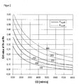
- Figure 2 shows the critical values for R n and R x calculated according to formula 9 as a function of the cardiac output CO for extracorporeal blood flows of 200, 300 and 400 ml / min.
- the critical values can also be determined or specified in some other way.
- Formula 4 can also be used to estimate the shunt flow Q a .
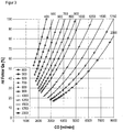
- Figure 3 shows the relative error calculated according to formula 6 in the determination of Q a at a blood flow of 300 ml / min assuming an error of the recirculation measurement of ⁇ 1% and the determination of CO and Q b of ⁇ 10% for values of Q a from 400 to 2000 ml / min. From this it becomes clear that the measurement accuracy is severely restricted at low Q a . Nevertheless, it is ensured that Q a > Q b in any case. Because the relative error for high If shunt flows decrease, the determination of Q a can be used to detect dangerously high shunt flows. Shunt flows> 2000 ml / min strain the patient's heart, which leads to increased mortality.
- a warning of excessive shunt flow can be generated based on a shunt flow determined from R n and CO. If a shunt flow of ⁇ 600 ml / min that is too low or a shunt flow that is too high is detected using the described method, the user can be asked to swap the needles for a more precise determination of the shunt flow, which is advantageously possible if one is already present Disposable for this is available. From the determination of R x , Q a can then be determined more precisely according to formula 3, the determination from R n and CO would then only serve as a preliminary screening.
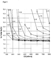
- Figure 4 shows a plot of the shunt flow Q a as a function of CO at different values of R x according to formula 5 with an extracorporeal blood flow of 300 ml / min. From this it can be seen that, especially at low shunt flows ( ⁇ 800 ml / min), the shunt flow can be determined solely from the measured recirculation R x with exchanged needles and that the value of the CO only slightly influences the value of the shunt flow if Q a ⁇ Is 1 ⁇ 4 CO. This is also in Figure 5 to recognize where the relative error in the determination of Q a according to formula 7 was applied with an extracorporeal blood flow of 300 ml / min.
- the shunt flow can be measured simply by measuring the recirculation with exchanged needles can be determined without the need for a recirculation measurement in normal needle orientation. This can significantly reduce the time required to determine the shunt flow. Needle swapping must generally be done manually by the user using an appropriate disposable. In the case of an incorrectly exchanged needle after the needle has been recognized from the measurement of the recirculation and the CO, the shunt flow can be specified immediately using Formula 5.
- R n, crit ⁇ R ⁇ R x, crit there is a partial recirculation between arterial and venous needles, which can result from an unfavorable positioning of the needles (eg too close to each other).
- the extracorporeal blood flow can exceed the shunt flow.
- the evaluation and control unit 18 is designed to distinguish between these two scenarios in such a way that a recirculation measurement is automatically carried out with reduced blood flow Q b ′ and the values are determined again. If the then determined value R 'lies below R' n, crit , Q a lies between Q b 'and Q b .
- the present invention provides a possibility of recognizing an above all excessively high shunt flow.
- a very high shunt flow is medically undesirable.
- the recirculation is determined, for example, using a temperature bolus, and the cardiac output is determined, for example, using an oscillometric blood pressure measurement.
- the shunt flow is calculated from both using formula 4. This can be determined especially with very high rivers with a relatively small error.
- the invention allows the determination of two limit values of the recirculation and the derivation of corresponding conclusions. Another aspect of the invention is particularly concerned with the comparison of the recirculation with limit values and the derivation of conclusions, detached from how the limit values are determined.
Landscapes
- Health & Medical Sciences (AREA)
- Heart & Thoracic Surgery (AREA)
- Vascular Medicine (AREA)
- Biomedical Technology (AREA)
- Engineering & Computer Science (AREA)
- Anesthesiology (AREA)
- Cardiology (AREA)
- Hematology (AREA)
- Life Sciences & Earth Sciences (AREA)
- Animal Behavior & Ethology (AREA)
- General Health & Medical Sciences (AREA)
- Public Health (AREA)
- Veterinary Medicine (AREA)
- External Artificial Organs (AREA)
- Measuring Pulse, Heart Rate, Blood Pressure Or Blood Flow (AREA)
Description
Die Erfindung betrifft ein Blutbehandlungsgerät mit einem extrakorporalen Blutkreislauf, der eine arterielle Leitung, eine Blutpumpe, eine Blutbehandlungseinheit und eine venöse Leitung umfasst, wobei die arterielle und venöse Leitung mit einem Blutgefäß eines Patienten verbunden werden können und wobei das Blutbehandlungsgerät eine Auswerte- und Steuereinheit zur Bestimmung des Blutflusses im beanspruchten Gefäß des Patienten aufweist.The invention relates to a blood treatment device with an extracorporeal blood circuit, which comprises an arterial line, a blood pump, a blood treatment unit and a venous line, wherein the arterial and venous line can be connected to a blood vessel of a patient and wherein the blood treatment device is an evaluation and control unit Determination of blood flow in the patient's stressed vessel.
Die Voraussetzung für eine effiziente extrakorporale Blutbehandlung, beispielsweise eine effiziente Dialyse ist das Vorhandensein eines funktionierenden Gefäßzugangs.The prerequisite for efficient extracorporeal blood treatment, for example efficient dialysis, is the presence of a functioning vascular access.
Für die extrakorporale Blutbehandlung wird daher oftmals künstlich eine arteriovenöse Fistel hergestellt, meist im Unterarm zwischen der Arteria Radialis und der Vena Cephalica. Durch diesen Kurzschluss von Arterie und Vene wird der Gefäßdruck erhöht, was durch einen verringerten Gewebewiderstand bedingt ist. So wird ein hoher Blutfluss im beanspruchten Gefäß erreicht.For extracorporeal blood treatment, an arteriovenous fistula is often created artificially, usually in the forearm between the radial artery and the cephalic vein. This short circuit of the artery and vein increases the vascular pressure, which is due to a reduced tissue resistance. In this way, a high blood flow is achieved in the stressed vessel.
Um einen funktionierenden Gefäßzugang überdies sicherzustellen, werden in einschlägigen Richtlinien verschiedene Methoden empfohlen. Hierzu gehören die Messung der Rezirkulation bei der Entnahme aus dem Gefäßzugang und die Bestimmung des Flusses im Gefäßzugang, wie dies beispielsweise aus
Im Stand der Technik ist es beispielsweise aus der
Eine Aufgabe der Erfindung ist es, ein Gerät für die extrakorporale Blutbehandlung bereitzustellen, das eine einfache und verlässliche Messung des Blutflusses im Gefäßzugang ermöglicht.An object of the invention is to provide a device for extracorporeal blood treatment, which enables simple and reliable measurement of the blood flow in the vascular access.
Die Erfindung wird durch die Merkmale des unabhängigen Anspruchs 1 definiert.The invention is defined by the features of independent claim 1.
Vor diesem Hintergrund betrifft die Erfindung ein Blutbehandlungsgerät mit einem extrakorporalen Blutkreislauf, der eine arterielle Leitung, eine Blutpumpe, eine Blutbehandlungseinheit und eine venöse Leitung umfasst, wobei die arterielle und venöse Leitung mit einem Blutgefäß eines Patienten verbunden werden können und wobei das Blutbehandlungsgerät eine Auswerte- und Steuereinheit aufweist. Erfindungsgemäß ist das Blutbehandlungsgerät dadurch gekennzeichnet, dass die Auswerte- und Steuereinheit ausgebildet ist, um die folgenden Schritte auszuführen: (a1) Ermittlung der Blut-Rezirkulation in einem mit dem extrakorporalen Blutkreislauf verbundenen Blutgefäß des Patienten; und (b) Berechnung des Blutflusses in dem Blutgefäß unter Verwendung der nach (a1) ermittelten Blut-Rezirkulation und eines bereitgestellten oder ebenfalls zuvor ermittelten Wertes für das Herzzeitvolumen des Patienten.Against this background, the invention relates to a blood treatment device with an extracorporeal blood circuit, which comprises an arterial line, a blood pump, a blood treatment unit and a venous line, wherein the arterial and venous line can be connected to a patient's blood vessel, and wherein the blood treatment device can be used for an evaluation. and control unit. According to the invention, the blood treatment device is characterized in that the evaluation and control unit is designed to carry out the following steps: (a1) determining the blood recirculation in a blood vessel of the patient connected to the extracorporeal blood circuit; and (b) calculating blood flow in the blood vessel using the method of (a1) determined blood recirculation and a provided or also previously determined value for the cardiac output of the patient.
Bei dem Blutbehandlungsgerät kann es sich beispielsweise um ein Dialysegerät oder ein Apheresegerät handeln. Bei der Blutbehandlungseinheit kann es sich beispielsweise um einen Dialysator oder einen Plasmafilter handeln.The blood treatment device can be, for example, a dialysis device or an apheresis device. The blood treatment unit can be, for example, a dialyzer or a plasma filter.
In einer Ausführungsform weist das Blutbehandlungsgerät ferner einen Blutdrucksensor auf und die Auswerte- und Steuereinheit ist ausgebildet, um vor Schritt (b) ferner den folgenden Schritt durchzuführen: (a2) Ermittlung des Herzzeitvolumens des Patienten durch Auswertung des zeitlichen Verlaufs eines anhand des Blutdrucksensors gemessenen Druckpulses. Ferner kann der Blutdrucksensor geeignet sein, um den Blutdruck direkt am Patienten zu messen, beispielsweise am Arm oder Handgelenk des Patienten. Geeignete Drucksensoren umfassen piezoelektrische Drucksensoren.In one embodiment, the blood treatment device also has a blood pressure sensor and the evaluation and control unit is designed to carry out the following step before step (b): (a2) determining the patient's cardiac output by evaluating the time profile of a pressure pulse measured using the blood pressure sensor . Furthermore, the blood pressure sensor can be suitable for measuring the blood pressure directly on the patient, for example on the patient's arm or wrist. Suitable pressure sensors include piezoelectric pressure sensors.
Im Rahmen der Erfindung kann also vorgesehen sein, dass aus oszillometrischen Blutdruckmessungen der Cardiac Output (das Herzzeitvolumen) bestimmt wird. Die Auswertung derartiger oszillometrischer Blutdruckmessungen ist beispielsweise zur Bestimmung des Blutdrucks bekannt (vgl.
Pulsanalysebasierte Verfahren zur Bestimmung des Herzzeitvolumens sind im Stand der Technik bekannt. All diese Verfahren benutzen Pulskurven, um das Herzzeitvolumen zu bestimmen. Die Auswerte- und Steuereinheit des erfindungsgemäßen Blutbehandlungsgeräts kann ausgebildet sein, um das Herzzeitvolumen anhand eines derartigen pulsanalysebasierten Verfahrens zu ermitteln und sodann in Schritt (b) zu verwenden.Pulse analysis-based methods for determining cardiac output are known in the prior art. All of these methods use pulse curves to determine cardiac output. The evaluation and control unit of the blood treatment device according to the invention can be designed to determine the cardiac output using such a pulse analysis-based method and then to use it in step (b).
Geeignete pulsanalysebasierte Verfahren umfassen die Impulsantwortmethode, die beispielsweise in der
Bevorzugt ist die Ermittlung des Herzzeitvolumens aus dem mittleren arteriellen Blutdruck, dem zentralvenösen Druck und dem peripheren Widerstand, wie dies beispielsweise im kommerziell verfügbaren Gerät "Vicorder" der Fa. SMT medical GmbH zum Einsatz kommt.It is preferred to determine the cardiac output from the mean arterial blood pressure, the central venous pressure and the peripheral resistance, as is used, for example, in the commercially available "Vicorder" device from SMT medical GmbH.
In einer Ausführungsform weist das Blutbehandlungsgerät ferner einen in der arteriellen Leitung des extrakorporalen Blutkreislaufs angeordneten Bolus-Sensor auf und die Auswerte- und Steuereinheit ist ausgebildet, um den Schritt (a1) in der folgenden Weise durchzuführen: (a1) Ermittlung der Blut-Rezirkulation in einem mit dem extrakorporalen Blutkreislauf verbundenen Blutgefäß des Patienten unter Verwendung des Signals des Bolus-Sensors.In one embodiment, the blood treatment device also has a bolus sensor arranged in the arterial line of the extracorporeal blood circuit, and the evaluation and control unit is designed to carry out step (a1) in the following manner: (a1) determining the blood recirculation in a patient's blood vessel connected to the extracorporeal blood circuit using the signal from the bolus sensor.
In einer Ausführungsform weist das Blutbehandlungsgerät eine Steuereinheit und einen Aktor auf, wobei der Aktor derart ausgebildet ist, dass stromabwärts einer im extrakorporalen Blutkreislauf angeordneten Blutpumpe und/oder der Blutbehandlungseinheit eine Bolusgabe erfolgen kann, und wobei die Steuereinheit so ausgebildet ist, dass unter Verwendung des Aktors während eines Messintervalls ein oder mehrmals eine Bolusgabe erfolgt. Bei dem Aktor kann es sich beispielsweise um eine Heizung handeln, mit der ein Temperaturbolus erzeugt werden kann. Ferner kann es sich bei dem Aktor um ein in den extrakorporalen Blutkreislauf mündendes Zudosiersystem handeln, mit dem ein Konzentrationsbolus oder Temperaturbolus erzeugt werden kann.In one embodiment, the blood treatment device has a control unit and an actuator, the actuator being designed such that a bolus and / or the blood treatment unit arranged in the extracorporeal blood circuit and / or the blood treatment unit can be administered, and wherein the control unit is designed such that using the The actuator is bolused one or more times during a measurement interval. The actuator can be a heater, for example, with which a temperature bolus can be generated. Furthermore, the actuator can be a metering system which opens into the extracorporeal blood circuit and with which a concentration bolus or temperature bolus can be generated.
Vorzugsweise weist das Blutbehandlungsgerät ferner einen in der venösen Leitung des extrakorporalen Blutkreislaufs angeordneten Bolus-Sensor auf, wobei die Auswerte- und Steuereinheit ausgebildet ist, um die Blut-Rezirkulation im Gefäßabschnitt des Patienten unter Verwendung der Signale des arteriellen und venösen Bolus-Sensors zu bestimmen. Insbesondere kann vorgesehen sein, dass die Auswerte- und Steuereinheit hierbei die Ähnlichkeit der Signalverläufe und den zeitlichen Versatz der von den unterschiedlichen Sensoren erhaltenen Signale berücksichtigt.The blood treatment device preferably also has a bolus sensor arranged in the venous line of the extracorporeal blood circuit, the evaluation and control unit being designed to determine the blood recirculation in the vascular section of the patient using the signals from the arterial and venous bolus sensor . In particular, it can be provided that the evaluation and control unit in this case the similarity of the signal profiles and the temporal offset of the signals received from the different sensors is taken into account.
Bei dem oder den Bolussensoren kann es sich um Temperatursensoren handeln, um einen Temperaturbolus zu erkennen.The bolus sensor (s) can be temperature sensors in order to detect a temperature bolus.
Die Messung der Rezirkulation zwischen venöser und arterieller Nadel mittels Thermodilution wird beispielsweise in
In einer Ausführungsform ist die Auswerte- und Steuereinheit ausgebildet, um bei der Ermittlung des Blutflusses in Schritt (b) neben der Blut-Rezirkulation und dem Herzzeitvolumen ferner den extrakorporalen Blutfluss und den Abfluss von Flüssigkeit in der Blutbehandlungseinrichtung zu berücksichtigen. Der extrakorporale Blutfluss Qb kann beispielsweise durch Einstellung der Förderrate einer in der arteriellen Leitung vorhandenen Blutpumpe eingestellt werden. Bei dem Abfluss von Flüssigkeit in der Blutbehandlungseinrichtung kann es sich insbesondere um die Ultrafiltrationsrate handeln. Diese kann beispielsweise anhand einer UF-Pumpe eingestellt werden, die in einem ebenfalls an den Dialysator angeschlossenen Dialysierflüssigkeitssystem angeordnet ist.In one embodiment, the evaluation and control unit is designed to take into account the extracorporeal blood flow and the outflow of liquid in the blood treatment device in addition to the blood recirculation and the cardiac output when determining the blood flow in step (b). The extracorporeal blood flow Q b can be set, for example, by adjusting the delivery rate of a blood pump present in the arterial line. The outflow of liquid in the blood treatment device can in particular be the ultrafiltration rate. This can be set, for example, using a UF pump which is arranged in a dialysis fluid system which is also connected to the dialyzer.
In einer Ausführungsform ist die Auswerte- und Steuereinheit ausgebildet, um unter der Annahme, dass der Blutfluss im betroffenen Gefäß maximal einen bestimmten Anteil des Herzzeitvolumens erreichen kann, kritische Werte für die Rezirkulation für einen normalen und/oder inversen Anschluss der arteriellen und venösen Leitung am Blutgefäß zu definieren. Der maximale Anteil am Herzzeitvolumen, den der Blutfluss im betroffenen Gefäß maximal erreichen kann, kann beispielsweise bei 50% liegen. So können kritische Werte für die Rezirkulation bei normaler und inverser Nadelposition definiert werden. Die kritischen Werte unterscheiden sich je nach Fluss im extrakorporalen Blutkreislauf.In one embodiment, the evaluation and control unit is designed to assume critical values for the recirculation for a normal and / or inverse connection of the arterial and venous line on the assumption that the blood flow in the affected vessel can reach a maximum proportion of the cardiac output Define blood vessel. The maximum proportion of the cardiac output that the blood flow in the affected vessel can reach can be, for example, 50%. Critical values for the recirculation with normal and inverse needle positions can be defined. The critical values differ depending on the flow in the extracorporeal blood circulation.
In einer Ausführungsform ist die Auswerte- und Steuereinheit ausgebildet, um die ermittelte Rezirkulation mit diesen kritischen Werten zu vergleichen und auf der Grundlage des Vergleichs zu gruppieren.In one embodiment, the evaluation and control unit is designed to compare the determined recirculation with these critical values and to group it on the basis of the comparison.
In einer Ausführungsform weist das Gerät ferner eine Ausgabeeinheit auf, die mit der Auswerte- und Steuereinheit in Verbindung steht, wobei die Ausgabeeinheit und die Auswerte- und Steuereinheit so ausgebildet sind, um je nach Gruppenzugehörigkeit der ermittelten Rezirkulation ein unterschiedliches Signal an den Benutzer auszugeben. Die Ausgabeeinheit kann beispielsweise akustische und/oder visuelle Signale an den Benutzer ausgeben.In one embodiment, the device also has an output unit which is connected to the evaluation and control unit, the output unit and the evaluation and control unit being designed to output a different signal to the user depending on the group membership of the determined recirculation. The output unit can output acoustic and / or visual signals to the user, for example.
In einer Ausführungsform werden drei Gruppen unterschieden: (1) die ermittelte Rezirkulation liegt unterhalb des kritischen Werts für normalen Anschluss; (2) die ermittelte Rezirkulation liegt oberhalb des kritischen Werts für normalen Anschluss aber unterhalb des kritischen Werts für inversen Anschluss; und (3) die ermittelte Rezirkulation liegt oberhalb des kritischen Werts für inversen Anschluss.In one embodiment, three groups are distinguished: (1) the recirculation determined is below the critical value for normal connection; (2) the recirculation determined is above the critical value for normal connection but below the critical value for inverse connection; and (3) the recirculation determined is above the critical value for inverse connection.
Hinsichtlich der Signalausgabe kann beispielsweise dann, wenn die ermittelte Rezirkulation der Gruppe (1) zugeordnet werden kann, ein Signal ausgegeben werden, das auf einen korrekten Anschluss des extrakorporalen Blutkreislaufs am Gefäß hinweist, und/oder dann, wenn die ermittelte Rezirkulation der Gruppe (3) zugeordnet werden kann, ein Signal ausgegeben werden, das auf eine Vertauschung der arteriellen und venösen Anschlüsse hinweist.With regard to the signal output, for example, if the determined recirculation can be assigned to group (1), a signal can be output that indicates correct connection of the extracorporeal blood circuit to the vessel, and / or if the determined recirculation can be assigned to group (3 ) can be assigned, a signal can be output that indicates that the arterial and venous connections have been swapped.
In einer Ausführungsform ist die Auswerte- und Steuereinheit so ausgebildet, dass dann, wenn die ermittelte Rezirkulation der Gruppe (2) zugeordnet wurde, die Förderleistung der Blutpumpe verringert wird und die Durchführung der Schritte (a1) und (b) wiederholt wird.In one embodiment, the evaluation and control unit is designed in such a way that when the determined recirculation has been assigned to group (2), the delivery rate of the blood pump is reduced and the steps (a1) and (b) are repeated.
In einer Ausführungsform ist die Auswerte- und Steuereinheit ausgebildet, um ein Warnsignal auszugeben, wenn der ermittelte Blutfluss im betroffenen Gefäß einen oberen Schwellenwert übersteigt oder einen unteren Schwellenwert unterschreitet.In one embodiment, the evaluation and control unit is designed to output a warning signal when the blood flow determined in the affected vessel exceeds an upper threshold value or falls below a lower threshold value.
In diesem Fall kann eine Überprüfung des erfindungsgemäß ermittelten Wertes durch Vertauschen der arteriellen und venösen Nadeln und Anwendung eines vorbekannten Verfahrens angezeigt sein. Der untere Schwellenwert kann beispielsweise bei 300 oder 500 ml/min liegen und der obere Schwellenwert beispielsweise bei 2000 oder 1500 ml/min.In this case, a check of the value determined according to the invention by swapping the arterial and venous needles and using a previously known method can be indicated. The lower threshold value can be, for example, 300 or 500 ml / min and the upper threshold value, for example, 2000 or 1500 ml / min.
Die Auswerte- und Steuereinheit kann vorzugsweise die für die Datensammlung notwendigen Eingriffe im Dialysegerät (z.B. Betrieb der Blutpumpe bei einer bestimmten Rate oder Gabe eines Temperaturbolus) einleiten. Sie kann so ausgebildet sein, dass die ermittelten Daten oder Schlussfolgerungen (z.B. der Blutfluss im betroffenen Gefäß, korrekter oder inverser Anschluss der Nadeln, Signale hinsichtlich eines korrekten Zugangs, etc.) automatisch zur Steuerung des Gerätes verwendet werden.The evaluation and control unit can preferably initiate the interventions in the dialysis machine necessary for data collection (e.g. operation of the blood pump at a specific rate or administration of a temperature bolus). It can be designed so that the determined data or conclusions (e.g. blood flow in the affected vessel, correct or inverse connection of the needles, signals regarding correct access, etc.) are automatically used to control the device.
In einer Ausführungsform weist das Blutbehandlungsgerät eine akustische und/oder visuelle Ausgabeeinheit auf, mit welcher die von der Auswerte- und Steuereinheit ermittelten Daten oder Schlussfolgerungen (s.o.) an einen Benutzer ausgibt.In one embodiment, the blood treatment device has an acoustic and / or visual output unit with which the data or conclusions (see above) determined by the evaluation and control unit are output to a user.
Ferner umfasst die Erfindung ein Verfahren zur Bestimmung des Blutflusses in einem mit dem extrakorporalen Blutkreislauf einer vorzugsweise erfindungsgemäßen Blutbehandlungseinrichtung verbundenen Blutgefäß eines Patienten. Dabei ist vorgesehen, die Rezirkulation im Gefäß zu bestimmen und unter Zugrundelegung dieser Rezirkulation sowie eines ebenfalls bestimmten oder anderweitig abgeschätzten Wertes für das Herzzeitvolumen den Blutfluss im betroffenen Blutgefäß des Patienten zu bestimmen.Furthermore, the invention comprises a method for determining the blood flow in a patient's blood vessel connected to the extracorporeal blood circuit of a blood treatment device preferably according to the invention. It is provided to determine the recirculation in the vessel and to determine the blood flow in the affected blood vessel of the patient on the basis of this recirculation and a likewise determined or otherwise estimated value for the cardiac output.
Neben der eingangs genannten Aufgabe ist es ferner eine Aufgabe der Erfindung, ein Gerät für die extrakorporale Blutbehandlung bereitzustellen, das eine Feststellung der Qualität des Gefäßzugangs ermöglicht.In addition to the object mentioned at the outset, it is also an object of the invention to provide a device for extracorporeal blood treatment which enables the quality of the vascular access to be determined.
In diesem Zusammenhang betrifft die Erfindung ein Blutbehandlungsgerät mit einem extrakorporalen Blutkreislauf, der eine arterielle Leitung, eine Blutpumpe, eine Blutbehandlungseinheit und eine venöse Leitung umfasst, wobei die arterielle und venöse Leitung mit einem Blutgefäß eines Patienten verbunden werden können und wobei das Blutbehandlungsgerät eine Auswerte- und Steuereinheit aufweist. Erfindungsgemäß ist vorgesehen, dass die Auswerte- und Steuereinheit ausgebildet ist, um die Blut-Rezirkulation in einem mit dem extrakorporalen Blutkreislauf verbundenen Blutgefäß des Patienten zu ermitteln und die ermittelte Rezirkulation mit ebenfalls ermittelten oder vorgegebenen kritischen Werten zu vergleichen und auf der Grundlage des Vergleichs zu gruppieren. Hier erfolgt eine Gruppierung der Rezirkulationswerte also gegebenenfalls ohne Ermittlung des Blutflusses im Blutgefäß.In this context, the invention relates to a blood treatment device with an extracorporeal blood circuit, which comprises an arterial line, a blood pump, a blood treatment unit and a venous line, wherein the arterial and venous line can be connected to a blood vessel of a patient, and wherein the blood treatment device can be used for evaluation. and control unit. It is provided according to the invention that the evaluation and control unit is designed to determine the blood recirculation in a blood vessel of the patient connected to the extracorporeal blood circuit and to compare the determined recirculation with likewise determined or predetermined critical values and on the basis of the comparison group. Here, the recirculation values are grouped, if necessary without determining the blood flow in the blood vessel.
Die Ermittlung der Blut-Rezirkulation kann dabei wie oben beschrieben erfolgen.The blood recirculation can be determined as described above.
Auch hier kann das Gerät ferner eine Ausgabeeinheit aufweisen, die mit der Auswerte- und Steuereinheit in Verbindung steht, wobei die Ausgabeeinheit und die Auswerte- und Steuereinheit so ausgebildet sind, um je nach Gruppenzugehörigkeit der ermittelten Rezirkulation ein unterschiedliches Signal an den Benutzer auszugeben. Die Ausgabe kann dabei wie oben beschrieben erfolgen.Here, too, the device can furthermore have an output unit which is connected to the evaluation and control unit, the output unit and the evaluation and control unit being designed in such a way that, depending on the group membership to output a different signal to the user of the determined recirculation. The output can be done as described above.
Alternativ oder zusätzlich zur Ausgabe an den Benutzer kann eine Reaktion des Blutbehandlungsgeräts initiiert werden.As an alternative or in addition to the output to the user, a reaction of the blood treatment device can be initiated.
Analog der ersten Ausgestaltung der Erfindung können auch hier drei Gruppen unterschieden werden: (1) die ermittelte Rezirkulation liegt unterhalb des kritischen Werts für normalen Anschluss; (2) die ermittelte Rezirkulation liegt oberhalb des kritischen Werts für normalen Anschluss aber unterhalb des kritischen Werts für inversen Anschluss; und (3) die ermittelte Rezirkulation liegt oberhalb des kritischen Werts für inversen Anschluss.Analogously to the first embodiment of the invention, three groups can also be distinguished here: (1) the recirculation determined is below the critical value for normal connection; (2) the recirculation determined is above the critical value for normal connection but below the critical value for inverse connection; and (3) the recirculation determined is above the critical value for inverse connection.
Ebenfalls analog der ersten Ausgestaltung der Erfindung kann die Auswerte- und Steuereinheit so ausgebildet sein, dass dann, wenn die ermittelte Rezirkulation der Gruppe (2) zugeordnet wurde, die Förderleistung der Blutpumpe verringert wird und die Ermittlung der Blut-Rezirkulation wiederholt wird.Similarly to the first embodiment of the invention, the evaluation and control unit can be designed such that when the determined recirculation has been assigned to group (2), the delivery rate of the blood pump is reduced and the determination of the blood recirculation is repeated.
Letztlich umfasst die Erfindung ein Verfahren zur Bestimmung der Qualität des Gefäßzugangs in einem mit dem extrakorporalen Blutkreislauf einer vorzugsweise erfindungsgemäßen Blutbehandlungseinrichtung verbundenen Blutgefäß eines Patienten. Dabei ist vorgesehen, die Rezirkulation im Gefäß zu bestimmen, die ermittelte Rezirkulation mit ebenfalls ermittelten oder vorgegebenen kritischen Werten zu vergleichen und auf der Grundlage des Vergleichs zu gruppieren.Ultimately, the invention comprises a method for determining the quality of the vascular access in a patient's blood vessel connected to the extracorporeal blood circuit of a blood treatment device preferably according to the invention. It is intended to determine the recirculation in the vessel, to compare the determined recirculation with likewise determined or predefined critical values and to group it on the basis of the comparison.
Weitere Einzelheiten und Vorteile der Erfindung ergeben sich aus dem nachfolgend anhand der Figuren dargestellten Ausführungsbeispiel. In den Figuren zeigen:
- Figur 1:
- eine schematische Darstellung einer Ausführungsform eines erfindungsgemäßen Dialysegeräts;
- Figur 2:
- eine Auftragung von erfindungsgemäß ermittelten kritischen Werten für den Anteil der Rezirkulationen Rn und Rx in normaler bzw. inverser Nadelposition in Abhängigkeit des Herzzeitvolumens CO für extrakorporale Blutflüsse
von und 400 ml/min; - Figur 3:
- eine Auftragung des relativen Fehlers bei der erfindungsgemäßen Bestimmung des Shuntflusses Qa bei
einem Blutfluss von 300 ml/min für Werte von Qa von 400bis 2000 ml/min; - Figur 4:
- eine Auftragung des Shuntflusses Qa in Abhängigkeit von CO bei verschiedenen Werten der Rezirkulation Rx in inverser Nadelpostition bei einem extrakorporalen
Blutfluss von 300 ml/min; und - Figur 5:
- eine Auftragung des relativen Fehlers bei der Bestimmung des Shuntflusses Qa bei vertauschten Nadeln und einem extrakorporalen
Blutfluss von 300 ml/min.
- Figure 1:
- a schematic representation of an embodiment of a dialysis machine according to the invention;
- Figure 2:
- plotting critical values determined according to the invention for the proportion of the recirculations R n and R x in normal or inverse needle position depending on the cardiac output CO for extracorporeal blood flows of 200, 300 and 400 ml / min;
- Figure 3:
- a plot of the relative error in the inventive determination of the shunt flow Q a with a blood flow of 300 ml / min for values of Q a from 400 to 2000 ml / min;
- Figure 4:
- plotting the shunt flow Q a as a function of CO at different values of the recirculation R x in an inverse needle position with an extracorporeal blood flow of 300 ml / min; and
- Figure 5:
- a plot of the relative error in determining the shunt flow Q a with exchanged needles and an extracorporeal blood flow of 300 ml / min.
Der in der Steuereinheit des erfindungsgemäßen Dialysegeräts gemäß Ausführungsbeispiel hinterlegte Algorithmus basiert auf dem nachfolgend erläuterten theoretischen Hintergrund.The algorithm stored in the control unit of the inventive dialysis machine according to the exemplary embodiment is based on the theoretical background explained below.
Die cardiopulmonare Rezirkulation bei Hämodialysepatienten mit einem Herzzeitvolumen CO, die über einen Gefäßzugang mit einem Shuntfluss Qa behandelt werden, ist definiert als 
Gemäß Schneditz (1998) kann durch Messung des Anteils der Rezirkulationen Rn und Rx in normaler bzw. inverser Nadelpostition der Shuntfluss Qa bei bekanntem extrakorporalem Blutfluss Qb und UF-Rate Of bestimmt werden. Hierfür werden folgende Größen definiert. 
Hiermit lautet die von Schneditz (1998) angegebene Formel. 
Ist der Cardiac Output bekannt, so kann Qa bei Kenntnis von nur einer der Größen Rn oder Rx berechnet werden. 

Nach dem Fehlerfortpflanzungsgesetz lässt sich der Fehler der Bestimmung von Qa aus CO und Rn wie folgt abschätzen.


Aus Formel 4 bzw. Formel 5 folgt.

Unter der physiologisch begründeten Annahme, dass der Shuntfluss Qa maximal 50% des Cardiac Output CO erreichen kann, ergeben sich für Rn und Rx kritische Werte, die bei einer Messung der Rezirkulation nicht über bzw. unterschritten werden können.

Die Messung des Shunt-Flusses ist aus verschiedenen Gründen gewünscht. Neben niedrigen sind auch gefährlich hohe Shunt-Flüsse wichtig zu erkennen (Steal-Syndrom). Gemäß der vorliegenden Idee berechnet sich der Shuntfluss Qa also zu Qa = CO-Qb/fn mit fn = Rn/1-Rn. Dabei ist R die Rezirkulationsfraktion und Qb der extrakorporale Blutfluss. Das Herzminutenvolumen CO und die Rezirkulation werden experimentell bestimmt. Somit lassen sich ohne Disposables und ohne Eingriff des Anwenders gefährlich hohe Shunt-Flüsse erkennen. Das Konzept kommt in einer Ausführungsform auch ohne die Einführung eines Bolus aus. Bei vertauschten Nadeln ist wegen der höheren Rezirkulation eine genauere Bestimmung auch bei niedrigen Shunt-Flüssen denkbar.Measuring the shunt flow is desired for several reasons. In addition to low, dangerously high shunt flows are also important to recognize (steal syndrome). According to the present idea, the shunt flow Q a is thus calculated as Q a = CO-Q b / f n with f n = R n / 1-R n . R is the recirculation fraction and Q b is the extracorporeal blood flow. Cardiac output CO and recirculation are determined experimentally. Dangerously high shunt flows can thus be identified without disposables and without user intervention. In one embodiment, the concept does not require the introduction of a bolus. With swapped needles, a more precise determination is also conceivable, even with low shunt flows, because of the higher recirculation.
Die Ermittlung des Herzzeitvolumens kann beispielsweise anhand der Formel ![]()
![]()
Eine schematische Darstellung einer Ausführungsform eines erfindungsgemäßen Dialysegeräts ist in
Das Dialysegerät ist in der Figur allgemein mit dem Bezugszeichen 1 gekennzeichnet. Es weist einen extrakorporalen Blutkreislauf 2 auf, der in bekannter Weise eine arterielle Leitung 3 mit einer Blutpumpe 4, einen Dialysator 5 und eine venöse Leitung 6 umfasst. Die arterielle Leitung 3 und die venöse Leitung 6 sind anhand einer arteriellen Nadel 7 bzw. einer venösen Nadel 8 mit einem Gefäß 9 eines Patienten 10 verbunden.The dialysis machine is generally identified in the figure by the reference number 1. It has an
Im Dialysator 5 ist eine semipermeable Membran 11 angeordnet, die innerhalb des Dialysators 5 die Blutkammer 12 von der Dialysierflüssigkeitskammer 13 trennt. An der Blutkammer 12 sind die arterielle und venöse Leitung 3 bzw. 6 des extrakorporalen Blutkreislaufs 2 angeschlossen. An der Dialysierflüssigkeitskammer 13 ist ein Dialysierflüssigkeitssystem 14 angeschlossen, welches eine Vorrichtung 15 zur Aufbereitung von Dialysierflüssigkeit, eine Zuleitung 16 zum Dialysator 5 und eine Ableitung 17 vom Dialysator 5 umfasst. In der Ableitung 17 kann eine in der Figur nicht dargestellte Ultrafiltrationspumpe angeordnet sein.A
Die Flussrichtungen des Blutes im extrakorporalen Blutkreislauf 2 und der Dialsysierflüssigkeit im Dialysierflüssigkeitssystem 14 sind in der Figur anhand von Pfeilen dargestellt.The directions of flow of the blood in the
Ferner umfasst das Dialysegerät 1 eine Auswerte- und Steuereinheit 18 sowie eine Ausgabeeinheit 19.The dialysis machine 1 further comprises an evaluation and
Sowohl an der arteriellen Leitung 3 als auch an der venösen Leitung 6 sind nahe der jeweiligen Nadeln Temperatursensoren 20 bzw. 21 angeordnet.Both on the
Das Gerät 1 umfasst ferner in der Figur nicht dargestellt Mittel zur Änderung der Bluttemperatur in der venösen Blutleitung. Diese Mittel können beispielsweise darin bestehen, dass die Temperatur der in der Vorrichtung 15 erzeugten Dialysierflüssigkeit nach Vorgabe der Auswerte- und Steuereinheit 18 mit dem Ziel einer Änderung der Bluttemperatur variiert werden. Alternativ kann die Änderung der Bluttemperatur z.B. auch durch am Blutschlauchsystem angebrachte Peltierelemente erfolgen.The device 1 further comprises means not shown in the figure for changing the blood temperature in the venous blood line. These means can consist, for example, in that the temperature of the dialysis liquid generated in the
Letztlich umfasst das Gerät 1 einen Sensor 22, um einen Pulsdruckkurvenverlauf des Patienten zu messen, der geeignet ist, CO zu bestimmen, z.B. durch einen Manschette am Oberarm. Der Sensor ist in einer in der Figur nicht dargestellten Weise mit der Auswerte- und Steuereinheit 18 verbunden.Ultimately, the device 1 comprises a
Im Betrieb der Vorrichtung saugt die Blutpumpe 4 über die arterielle Nadel 7 Blut aus dem Gefäß 9 des Patienten 10 in die arterielle Leitung 3 des extrakorporalen Blutkreislaufs 2 und pumpt das Blut anschließend durch den Dialysator 5, die venöse Leitung 6 und die venöse Nadel 8 zurück in das Gefäß 9 des Patienten 10. Nach Gabe eines Temperaturbolus wird der zeitliche Temperaturverlauf des entnommenen und zurückgegebenen Blutes an den Sensoren 20 und 21 gemessen und die Messwerte werden an die Auswerte- und Steuereinheit 18 übermittelt. Aus dem Temperaturverlauf wird dann in der Auswerte- und Steuereinheit 18 die Rezirkulation R wie in Schneditz (2003) beschrieben bestimmt. Ferner wird mittels oszillometrischer Blutdruckmessungen am Blutdrucksensor das Herzzeitvolumen bestimmt.During operation of the device, the blood pump 4 sucks blood from the
Alternativ kann der Cardiac Output bei bekanntem, beispielsweise aus echocardiographischen Untersuchungen stammendem oder als typischer Wert von 70 ml abgeschätztem Herz-Schlagvolumen VCO, durch Messung der Herzrate v, mittel CO = v·VCO abgeschätzt werden.Alternatively, the cardiac output can be estimated by measuring the heart rate v, mean CO = v · V CO, if the cardiac output V CO is known, for example comes from echocardiographic examinations or is estimated as a typical value of 70 ml.
Nach Bestimmung von R und CO und bei bekannter Förderrate der Blutpumpe 4 und Ultrafiltrationsrate werden in der Auswerte- und Steuereinheit 18 nun die oben näher dargestellten Berechnungen zur Ermittlung des Blutflusses im Gefäß 9 des Patienten 10 durchgeführt. Die Ergebnisse können beispielsweise an der Ausgabeeinheit 19 ausgegeben werden, über eine beliebige Art der Kommunikation wie beispielsweise über Netzwerk übermittelt werden und/oder automatisch für die Steuerung des Gerätes 1 verwendet werden.After determination of R and CO and with a known delivery rate of the blood pump 4 and ultrafiltration rate, the calculations and
Die Ergebnisse können in der nachfolgend beschriebenen Weise interpretiert bzw. genützt werden.The results can be interpreted or used in the manner described below.
Wird zeitnah zur Messung der Rezirkulation R das Herzzeitvolumen CO gemessen oder abgeschätzt, können zusammen mit den bekannten Werten für den extrakorporalen Blutfluss und UF Rate gemäß Formel 9 kritische Werte Rn,crit und Rx,crit für die Rezirkulationen Rn und Rx in normaler bzw. inverser Nadelposition berechnet und R mit diesen Werten verglichen werden.
Die kritischen Werte können in einer weiteren Ausgestaltung der Erfindung aber auch anderweitig bestimmt oder vorgegeben werden.In a further embodiment of the invention, however, the critical values can also be determined or specified in some other way.
Es lassen sich unterschiedliche Fälle unterscheiden, die unterschiedliche Schlussfolgerungen zulassen.Different cases can be distinguished, which allow different conclusions.
Ist R < Rn,crit, so liegt nur cardiopulmonare Rezirkulation vor. Der Shuntfluss ist daher größer als der extrakorporale Blutfluss, arterielle und venöse Nadel sind korrekt punktiert und an das Schlauchsystem konnektiert. Hierüber kann der Anwender mittels der Ausgabeeinheit 19 auf beliebige Weise informiert werden.If R <R n, crit , there is only cardiopulmonary recirculation. The shunt flow is therefore greater than the extracorporeal blood flow, arterial and venous needles are correctly punctured and connected to the tube system. The user can be informed about this in any way by means of the
Ferner kann mittels Formel 4 der Shuntfluss Qa abgeschätzt werden.
Ist R > Rx,crit, so ist die Gefäß-Rezirkulation so hoch, dass mit hoher Wahrscheinlichkeit eine Vertauschung von arterieller und venöser Nadel vorliegt. Auch hierüber kann der Anwender mittels der Ausgabeeinheit 19 auf beliebige Weise informiert werden.If R> R x, crit , the vascular recirculation is so high that there is a high probability that the arterial and venous needles have been swapped. The user can be informed about this in any way by means of the
Ist Rn,crit < R < Rx,crit, so liegt eine teilweise Rezirkulation zwischen arterieller und venöser Nadel vor, was durch eine ungünstige Positionierung der Nadeln (z.B. zu dicht nebeneinander) entstehen kann. Alternativ kann der extrakorporale Blutfluss den Shuntfluss überschreiten. Es kann vorgesehen sein, dass die Auswerte- und Steuereinheit 18 zur Unterscheidung dieser beiden Szenarien so ausgebildet ist, dass automatisch eine Rezirkulationsmessung bei reduziertem Blutfluss Qb' durchgeführt wird und die Werte erneut ermittelt werden. Liegt der dann bestimmte Wert R' unterhalb von R'n,crit, so liegt Qa zwischen Qb' und Qb.If R n, crit <R <R x, crit , there is a partial recirculation between arterial and venous needles, which can result from an unfavorable positioning of the needles (eg too close to each other). Alternatively, the extracorporeal blood flow can exceed the shunt flow. It can be provided that the evaluation and
Zusammenfassend ergibt sich, dass die vorliegende Erfindung eine Möglichkeit zur Erkennung eines vor allem übermäßig hohen Shuntflusses an die Hand gibt. Ein sehr hoher Shuntfluss ist medizinisch unerwünscht. Gemäß der Erfindung wird beispielsweise anhand Gabe eines Temperaturbolus die Rezirkulation und beispielsweise anhand einer oszillometrischen Blutdruckmessung das Herzzeitvolumen bestimmt. Aus beiden wird anhand der Formel 4 der Shuntfluss berechnet. Dieser lässt sich vor allem bei sehr hohen Flüssen mit relativ geringem Fehler bestimmen. Ferner erlaubt die Erfindung die Bestimmung zweier Grenzwerte der Rezirkulation und die Ableitung entsprechender Schlussfolgerungen. Ein weiterer Aspekt der Erfindung beschäftigt sich insbesondere mit dem Vergleich der Rezirkulation mit Grenzwerten und der Ableitung von Schlussfolgerungen, losgelöst davon, wie die Grenzwerte ermittelt werden.In summary, it can be seen that the present invention provides a possibility of recognizing an above all excessively high shunt flow. A very high shunt flow is medically undesirable. According to the invention, the recirculation is determined, for example, using a temperature bolus, and the cardiac output is determined, for example, using an oscillometric blood pressure measurement. The shunt flow is calculated from both using formula 4. This can be determined especially with very high rivers with a relatively small error. Furthermore, the invention allows the determination of two limit values of the recirculation and the derivation of corresponding conclusions. Another aspect of the invention is particularly concerned with the comparison of the recirculation with limit values and the derivation of conclusions, detached from how the limit values are determined.
Claims (9)
- A blood treatment device (1) having an extracorporeal blood circuit which comprises an arterial line, a blood pump, a blood treatment unit and a venous line, wherein the arterial and venous lines can be connected to a blood vessel of a patient, and wherein the blood treatment device has an evaluation and control unit,
wherein the evaluation and control unit is configured to carry out the following steps:(a1) determining the blood recirculation in a blood vessel of the patient connected to the extracorporeal blood circuit; and(b) calculating the blood flow in the blood vessel using the blood recirculation determined in accordance with (a1) and using a provided value or a value likewise previously determined for the cardiac output of the patientand characterized in that
the evaluation and control unit is configured furthermore to take account of the extracorporeal blood flow and the outflow of fluid in the blood treatment apparatus, in addition to the blood recirculation and the cardiac output, when determining the blood flow in step (b). - A blood treatment device in accordance with claim 1, characterized in that the blood treatment device furthermore has a blood pressure sensor; and in that the evaluation and control unit is configured furthermore to carry out the following step:
(a2) determining the cardiac output of the patient by evaluating the time progression of a pressure pulse measured using the blood pressure sensor. - A blood treatment device in accordance with one of the preceding claims, characterized in that the blood treatment device furthermore has a bolus sensor arranged in the arterial line of the extracorporeal blood circuit; and in that the evaluation and control unit is configured to carry out step (a1) in the following manner:
(a1) determining the blood recirculation in a blood vessel of the patient connected to the extracorporeal blood circuit using the signal of the bolus sensor. - A blood treatment device in accordance with one of the preceding claims, characterized in that the evaluation and control unit is configured to define critical values for the recirculation for a normal and/or inverse connection of the arterial and venous lines to the blood vessel under the assumption that the blood flow in the corresponding vessel can achieve a specific portion of the cardiac output as a maximum.
- A blood treatment device in accordance with claim 4, characterized in that the evaluation and control unit is configured to compare the determined recirculation with these critical values and to group it on the basis of the comparison.
- A blood treatment device in accordance with claim 5, characterized in that the device furthermore has an output unit which communicates with the evaluation and control unit, wherein the output unit and the evaluation and control unit are configured to output a different signal to the user depending on the group association of the determined recirculation.
- A blood treatment device in accordance with claim 5 or claim 6, characterized in that three groups are distinguished:(1) the determined recirculation is below the critical value for a normal connection;(2) the determined recirculation is above the critical value for a normal connection, but below the critical value for an inverse connection; and(3) the determined recirculation is above the critical value for an inverse connection.
- A blood treatment device in accordance with claim 7, characterized in that the evaluation and control unit is configured such that, when the determined recirculation has been associated with group (2), the conveying performance of the blood pump is reduced and the carrying out of steps (a1) and (b) is repeated.
- A blood treatment device in accordance with one of the preceding claims, characterized in that the evaluation and control unit is configured to output a warning signal when the determined blood flow in the respective vessel exceeds an upper threshold value or falls below a lower threshold value.
Applications Claiming Priority (2)
| Application Number | Priority Date | Filing Date | Title |
|---|---|---|---|
| DE102016001710.4A DE102016001710B4 (en) | 2016-02-15 | 2016-02-15 | Device for extracorporeal blood treatment with an evaluation and control unit |
| PCT/EP2017/000214 WO2017140424A2 (en) | 2016-02-15 | 2017-02-15 | Equipment for extra-corporeal treatment of blood, comprising an evaluation- and control unit |
Publications (2)
| Publication Number | Publication Date |
|---|---|
| EP3416701A2 EP3416701A2 (en) | 2018-12-26 |
| EP3416701B1 true EP3416701B1 (en) | 2020-04-01 |
Family
ID=58046619
Family Applications (1)
| Application Number | Title | Priority Date | Filing Date |
|---|---|---|---|
| EP17705314.7A Active EP3416701B1 (en) | 2016-02-15 | 2017-02-15 | Equipment for extra-corporeal treatment of blood, comprising an evaluation- and control unit |
Country Status (7)
| Country | Link |
|---|---|
| US (1) | US11529450B2 (en) |
| EP (1) | EP3416701B1 (en) |
| JP (1) | JP7082577B2 (en) |
| CN (1) | CN108697841B (en) |
| CA (1) | CA3014542A1 (en) |
| DE (1) | DE102016001710B4 (en) |
| WO (1) | WO2017140424A2 (en) |
Families Citing this family (10)
| Publication number | Priority date | Publication date | Assignee | Title |
|---|---|---|---|---|
| DE102016119259A1 (en) | 2016-10-10 | 2018-04-12 | B. Braun Avitum Ag | Apparatus and method for recirculation measurement |
| US11253205B2 (en) * | 2017-08-16 | 2022-02-22 | Seiko Epson Corporation | Pulse pressure and blood pressure analysis device, pulse pressure and blood pressure analysis method, and program |
| US11317873B2 (en) | 2017-08-16 | 2022-05-03 | Seiko Epson Corporation | Biological analysis device, biological analysis method, and program |
| US11116414B2 (en) | 2017-08-16 | 2021-09-14 | Seiko Epson Corporation | Biological analysis device, biological analysis method, and program |
| JP7061509B2 (en) * | 2018-04-26 | 2022-04-28 | 日機装株式会社 | Blood purification device |
| CN109394200B (en) * | 2018-12-16 | 2021-10-19 | 冯兴怀 | Microcirculation pulse blood flow monitoring system and method for liquid treatment and volume management |
| CN113678207A (en) * | 2019-01-31 | 2021-11-19 | 普尔松医疗系统公司 | System, computer system and computer program for determining cardiovascular parameters |
| CN110215548B (en) * | 2019-06-17 | 2021-10-01 | 湖州市妇幼保健院 | Blood recovery unit based on thrombus filtration |
| CN110251116A (en) * | 2019-07-15 | 2019-09-20 | 河北医科大学第一医院 | A kind of vascular access flow detector and its calculation method |
| JP7435017B2 (en) | 2020-02-26 | 2024-02-21 | ニプロ株式会社 | Dialysis equipment, method for measuring cardiac output of dialysis patients, calculation device and computer program |
Family Cites Families (17)
| Publication number | Priority date | Publication date | Assignee | Title |
|---|---|---|---|---|
| NL9100150A (en) | 1991-01-29 | 1992-08-17 | Tno | METHOD FOR DETERMINING THE BATTLE VOLUME AND THE HEART MINUTE VOLUME OF THE HUMAN HEART. |
| US6153109A (en) * | 1994-09-16 | 2000-11-28 | Transonic Systmes, Inc. | Method and apparatus to measure blood flow rate in hemodialysis shunts |
| US5687733A (en) * | 1995-10-26 | 1997-11-18 | Baxter International Inc. | System and method for estimating cardiac output |
| DE19541783C1 (en) | 1995-11-09 | 1997-03-27 | Fresenius Ag | Method for operating a blood treatment device for determining hemodynamic parameters during an extracorporeal blood treatment and device for determining hemodynamic parameters during an extracorporeal blood treatment |
| DE19702441C1 (en) * | 1997-01-24 | 1998-02-26 | Fresenius Medical Care De Gmbh | Dialysis recirculation monitoring |
| DE19917197C1 (en) | 1999-04-16 | 2000-07-27 | Fresenius Medical Care De Gmbh | Method to determine blood flow in vessel entrance of haemodialysis unit; involves measuring arterial and venous pressures when vessel entrance is open to allow blood flow and closed to prevent blood flow |
| DE10259437B3 (en) | 2002-12-19 | 2004-09-16 | Fresenius Medical Care Deutschland Gmbh | Method and device for determining blood flow in a blood-carrying line |
| US7815578B2 (en) | 2003-02-10 | 2010-10-19 | Massachusetts Institute Of Technology | Methods and apparatus for determining cardiac output |
| DE102005001051B4 (en) * | 2005-01-07 | 2007-10-31 | Fresenius Medical Care Deutschland Gmbh | Apparatus and method for detecting complications during extracorporeal blood treatment |
| US8905939B2 (en) * | 2006-07-13 | 2014-12-09 | Edwards Lifesciences Corporation | Method and apparatus for continuous assessment of a cardiovascular parameter using the arterial pulse pressure propagation time and waveform |
| JP4573860B2 (en) * | 2007-08-22 | 2010-11-04 | 日機装株式会社 | Blood purification equipment |
| DE102007056475A1 (en) | 2007-11-22 | 2009-06-04 | Fresenius Medical Care Deutschland Gmbh | A method and apparatus for determining recirculation in a fistula or cardiopulmonary recirculation, and a blood treatment apparatus having means for determining fistula recirculation or cardiopulmonary recirculation percentage |
| CN101176663B (en) * | 2007-12-06 | 2010-10-27 | 山东大学 | Non-invasive cardiac output detecting methods and apparatus based on sphygmus wave |
| EP2519279B1 (en) * | 2009-12-28 | 2015-04-22 | Gambro Lundia AB | Device and method for monitoring a fluid flow rate in a cardiovascular system |
| DE102010015664A1 (en) | 2010-04-20 | 2011-10-20 | Up-Med Gmbh | Method and device for determining the fistula flow of a fistula for dialysis treatment |
| DE102012007081B4 (en) | 2012-04-11 | 2015-04-02 | Fresenius Medical Care Deutschland Gmbh | Method and measuring and calculating unit for long-term monitoring of the arterial vascular stiffness and vascular calcification of a patient |
| DE102013103218A1 (en) * | 2013-03-28 | 2014-10-02 | B. Braun Avitum Ag | Method and device for detecting recirculation in a shunt |
-
2016
- 2016-02-15 DE DE102016001710.4A patent/DE102016001710B4/en active Active
-
2017
- 2017-02-15 CA CA3014542A patent/CA3014542A1/en active Pending
- 2017-02-15 CN CN201780011559.6A patent/CN108697841B/en active Active
- 2017-02-15 EP EP17705314.7A patent/EP3416701B1/en active Active
- 2017-02-15 US US15/998,566 patent/US11529450B2/en active Active
- 2017-02-15 JP JP2018561302A patent/JP7082577B2/en active Active
- 2017-02-15 WO PCT/EP2017/000214 patent/WO2017140424A2/en active Application Filing
Non-Patent Citations (1)
| Title |
|---|
| None * |
Also Published As
| Publication number | Publication date |
|---|---|
| US11529450B2 (en) | 2022-12-20 |
| CN108697841A (en) | 2018-10-23 |
| JP7082577B2 (en) | 2022-06-08 |
| CA3014542A1 (en) | 2017-08-24 |
| EP3416701A2 (en) | 2018-12-26 |
| DE102016001710A1 (en) | 2017-08-17 |
| WO2017140424A2 (en) | 2017-08-24 |
| JP2019510598A (en) | 2019-04-18 |
| DE102016001710B4 (en) | 2022-08-25 |
| WO2017140424A3 (en) | 2017-10-12 |
| CN108697841B (en) | 2021-12-10 |
| US20200276380A1 (en) | 2020-09-03 |
Similar Documents
| Publication | Publication Date | Title |
|---|---|---|
| EP3416701B1 (en) | Equipment for extra-corporeal treatment of blood, comprising an evaluation- and control unit | |
| EP2263717B1 (en) | Method and device for recognition of stenoses in extra-corporal blood treatment | |
| DE19746377C1 (en) | Blood treatment device with a device for continuous monitoring of the patient's blood pressure | |
| EP2040776B1 (en) | Method and device for monitoring an extracorporeal blood circuit | |
| EP2384138B1 (en) | Device for determining and/or monitoring fistula patency on the basis of an amplitude of the heart pressure signal during a blood treatment | |
| DE69634546T2 (en) | METHOD AND DEVICE FOR RECORDING THE CONDITION OF BLOOD BATTERY ACCESS | |
| EP2259812B1 (en) | Method and device for monitoring a vascular access and extracorporeal blood treatment device comprising a device for monitoring a vascular access | |
| EP3019211B1 (en) | Blood treatment device | |
| EP2533827B1 (en) | Device and method for monitoring a vascular access for an extracorporeal blood treatment | |
| EP2913073B1 (en) | Device for detecting a venous needle disconnection | |
| EP1480695B1 (en) | Device for determining the hematocrit and/or blood volume | |
| WO2014044365A1 (en) | Device and method for detecting recirculation during an extracorporeal blood treatment | |
| EP2714133B1 (en) | Blood treatment device | |
| EP2999498B1 (en) | Device for monitoring an extracorporeal blood circuit | |
| DE10033192B4 (en) | Method for detecting arterial enema problems during extracorporeal blood treatment and extracorporeal blood treatment device | |
| EP3393547B1 (en) | Dialysis device with means for detecting a shunt recirculation | |
| EP4297817A1 (en) | Method for analyzing a measured pressure value, and devices | |
| EP3131603B1 (en) | Device for withdrawing blood from an extracorporeal blood circuit while pressure control is performed | |
| EP2988661B1 (en) | Control unit and method for determining a pressure in a blood vessel, especially in an arteriovenous fistula | |
| EP3305345B1 (en) | Device for recirculation measurement | |
| DE10254988A1 (en) | Monitoring pressure in vessel entrance during extracorporal blood treatment involves computing change in pressure in vessel entrance from measured arterial or venous pressure, comparing with threshold |
Legal Events
| Date | Code | Title | Description |
|---|---|---|---|
| STAA | Information on the status of an ep patent application or granted ep patent |
Free format text: STATUS: UNKNOWN |
|
| STAA | Information on the status of an ep patent application or granted ep patent |
Free format text: STATUS: THE INTERNATIONAL PUBLICATION HAS BEEN MADE |
|
| PUAI | Public reference made under article 153(3) epc to a published international application that has entered the european phase |
Free format text: ORIGINAL CODE: 0009012 |
|
| STAA | Information on the status of an ep patent application or granted ep patent |
Free format text: STATUS: REQUEST FOR EXAMINATION WAS MADE |
|
| 17P | Request for examination filed |
Effective date: 20180911 |
|
| AK | Designated contracting states |
Kind code of ref document: A2 Designated state(s): AL AT BE BG CH CY CZ DE DK EE ES FI FR GB GR HR HU IE IS IT LI LT LU LV MC MK MT NL NO PL PT RO RS SE SI SK SM TR |
|
| AX | Request for extension of the european patent |
Extension state: BA ME |
|
| DAV | Request for validation of the european patent (deleted) | ||
| DAX | Request for extension of the european patent (deleted) | ||
| GRAP | Despatch of communication of intention to grant a patent |
Free format text: ORIGINAL CODE: EPIDOSNIGR1 |
|
| STAA | Information on the status of an ep patent application or granted ep patent |
Free format text: STATUS: GRANT OF PATENT IS INTENDED |
|
| INTG | Intention to grant announced |
Effective date: 20191017 |
|
| GRAS | Grant fee paid |
Free format text: ORIGINAL CODE: EPIDOSNIGR3 |
|
| GRAA | (expected) grant |
Free format text: ORIGINAL CODE: 0009210 |
|
| STAA | Information on the status of an ep patent application or granted ep patent |
Free format text: STATUS: THE PATENT HAS BEEN GRANTED |
|
| AK | Designated contracting states |
Kind code of ref document: B1 Designated state(s): AL AT BE BG CH CY CZ DE DK EE ES FI FR GB GR HR HU IE IS IT LI LT LU LV MC MK MT NL NO PL PT RO RS SE SI SK SM TR |
|
| REG | Reference to a national code |
Ref country code: GB Ref legal event code: FG4D Free format text: NOT ENGLISH |
|
| REG | Reference to a national code |
Ref country code: AT Ref legal event code: REF Ref document number: 1250546 Country of ref document: AT Kind code of ref document: T Effective date: 20200415 Ref country code: CH Ref legal event code: EP |
|
| REG | Reference to a national code |
Ref country code: DE Ref legal event code: R096 Ref document number: 502017004488 Country of ref document: DE |
|
| REG | Reference to a national code |
Ref country code: IE Ref legal event code: FG4D Free format text: LANGUAGE OF EP DOCUMENT: GERMAN |
|
| REG | Reference to a national code |
Ref country code: SE Ref legal event code: TRGR |
|
| PG25 | Lapsed in a contracting state [announced via postgrant information from national office to epo] |
Ref country code: BG Free format text: LAPSE BECAUSE OF FAILURE TO SUBMIT A TRANSLATION OF THE DESCRIPTION OR TO PAY THE FEE WITHIN THE PRESCRIBED TIME-LIMIT Effective date: 20200701 |
|
| REG | Reference to a national code |
Ref country code: NL Ref legal event code: MP Effective date: 20200401 |
|
| REG | Reference to a national code |
Ref country code: LT Ref legal event code: MG4D |
|
| PG25 | Lapsed in a contracting state [announced via postgrant information from national office to epo] |
Ref country code: CZ Free format text: LAPSE BECAUSE OF FAILURE TO SUBMIT A TRANSLATION OF THE DESCRIPTION OR TO PAY THE FEE WITHIN THE PRESCRIBED TIME-LIMIT Effective date: 20200401 Ref country code: PT Free format text: LAPSE BECAUSE OF FAILURE TO SUBMIT A TRANSLATION OF THE DESCRIPTION OR TO PAY THE FEE WITHIN THE PRESCRIBED TIME-LIMIT Effective date: 20200817 Ref country code: LT Free format text: LAPSE BECAUSE OF FAILURE TO SUBMIT A TRANSLATION OF THE DESCRIPTION OR TO PAY THE FEE WITHIN THE PRESCRIBED TIME-LIMIT Effective date: 20200401 Ref country code: FI Free format text: LAPSE BECAUSE OF FAILURE TO SUBMIT A TRANSLATION OF THE DESCRIPTION OR TO PAY THE FEE WITHIN THE PRESCRIBED TIME-LIMIT Effective date: 20200401 Ref country code: GR Free format text: LAPSE BECAUSE OF FAILURE TO SUBMIT A TRANSLATION OF THE DESCRIPTION OR TO PAY THE FEE WITHIN THE PRESCRIBED TIME-LIMIT Effective date: 20200702 Ref country code: NO Free format text: LAPSE BECAUSE OF FAILURE TO SUBMIT A TRANSLATION OF THE DESCRIPTION OR TO PAY THE FEE WITHIN THE PRESCRIBED TIME-LIMIT Effective date: 20200701 Ref country code: IS Free format text: LAPSE BECAUSE OF FAILURE TO SUBMIT A TRANSLATION OF THE DESCRIPTION OR TO PAY THE FEE WITHIN THE PRESCRIBED TIME-LIMIT Effective date: 20200801 Ref country code: NL Free format text: LAPSE BECAUSE OF FAILURE TO SUBMIT A TRANSLATION OF THE DESCRIPTION OR TO PAY THE FEE WITHIN THE PRESCRIBED TIME-LIMIT Effective date: 20200401 |
|
| PG25 | Lapsed in a contracting state [announced via postgrant information from national office to epo] |
Ref country code: RS Free format text: LAPSE BECAUSE OF FAILURE TO SUBMIT A TRANSLATION OF THE DESCRIPTION OR TO PAY THE FEE WITHIN THE PRESCRIBED TIME-LIMIT Effective date: 20200401 Ref country code: LV Free format text: LAPSE BECAUSE OF FAILURE TO SUBMIT A TRANSLATION OF THE DESCRIPTION OR TO PAY THE FEE WITHIN THE PRESCRIBED TIME-LIMIT Effective date: 20200401 Ref country code: HR Free format text: LAPSE BECAUSE OF FAILURE TO SUBMIT A TRANSLATION OF THE DESCRIPTION OR TO PAY THE FEE WITHIN THE PRESCRIBED TIME-LIMIT Effective date: 20200401 |
|
| PG25 | Lapsed in a contracting state [announced via postgrant information from national office to epo] |
Ref country code: AL Free format text: LAPSE BECAUSE OF FAILURE TO SUBMIT A TRANSLATION OF THE DESCRIPTION OR TO PAY THE FEE WITHIN THE PRESCRIBED TIME-LIMIT Effective date: 20200401 |
|
| REG | Reference to a national code |
Ref country code: DE Ref legal event code: R097 Ref document number: 502017004488 Country of ref document: DE |
|
| PG25 | Lapsed in a contracting state [announced via postgrant information from national office to epo] |
Ref country code: RO Free format text: LAPSE BECAUSE OF FAILURE TO SUBMIT A TRANSLATION OF THE DESCRIPTION OR TO PAY THE FEE WITHIN THE PRESCRIBED TIME-LIMIT Effective date: 20200401 Ref country code: SM Free format text: LAPSE BECAUSE OF FAILURE TO SUBMIT A TRANSLATION OF THE DESCRIPTION OR TO PAY THE FEE WITHIN THE PRESCRIBED TIME-LIMIT Effective date: 20200401 Ref country code: EE Free format text: LAPSE BECAUSE OF FAILURE TO SUBMIT A TRANSLATION OF THE DESCRIPTION OR TO PAY THE FEE WITHIN THE PRESCRIBED TIME-LIMIT Effective date: 20200401 Ref country code: DK Free format text: LAPSE BECAUSE OF FAILURE TO SUBMIT A TRANSLATION OF THE DESCRIPTION OR TO PAY THE FEE WITHIN THE PRESCRIBED TIME-LIMIT Effective date: 20200401 Ref country code: ES Free format text: LAPSE BECAUSE OF FAILURE TO SUBMIT A TRANSLATION OF THE DESCRIPTION OR TO PAY THE FEE WITHIN THE PRESCRIBED TIME-LIMIT Effective date: 20200401 |
|
| PLBE | No opposition filed within time limit |
Free format text: ORIGINAL CODE: 0009261 |
|
| STAA | Information on the status of an ep patent application or granted ep patent |
Free format text: STATUS: NO OPPOSITION FILED WITHIN TIME LIMIT |
|
| PG25 | Lapsed in a contracting state [announced via postgrant information from national office to epo] |
Ref country code: PL Free format text: LAPSE BECAUSE OF FAILURE TO SUBMIT A TRANSLATION OF THE DESCRIPTION OR TO PAY THE FEE WITHIN THE PRESCRIBED TIME-LIMIT Effective date: 20200401 Ref country code: SK Free format text: LAPSE BECAUSE OF FAILURE TO SUBMIT A TRANSLATION OF THE DESCRIPTION OR TO PAY THE FEE WITHIN THE PRESCRIBED TIME-LIMIT Effective date: 20200401 |
|
| 26N | No opposition filed |
Effective date: 20210112 |
|
| PG25 | Lapsed in a contracting state [announced via postgrant information from national office to epo] |
Ref country code: SI Free format text: LAPSE BECAUSE OF FAILURE TO SUBMIT A TRANSLATION OF THE DESCRIPTION OR TO PAY THE FEE WITHIN THE PRESCRIBED TIME-LIMIT Effective date: 20200401 |
|
| PG25 | Lapsed in a contracting state [announced via postgrant information from national office to epo] |
Ref country code: MC Free format text: LAPSE BECAUSE OF FAILURE TO SUBMIT A TRANSLATION OF THE DESCRIPTION OR TO PAY THE FEE WITHIN THE PRESCRIBED TIME-LIMIT Effective date: 20200401 |
|
| REG | Reference to a national code |
Ref country code: BE Ref legal event code: MM Effective date: 20210228 |
|
| PG25 | Lapsed in a contracting state [announced via postgrant information from national office to epo] |
Ref country code: CH Free format text: LAPSE BECAUSE OF NON-PAYMENT OF DUE FEES Effective date: 20210228 Ref country code: LI Free format text: LAPSE BECAUSE OF NON-PAYMENT OF DUE FEES Effective date: 20210228 Ref country code: LU Free format text: LAPSE BECAUSE OF NON-PAYMENT OF DUE FEES Effective date: 20210215 |
|
| PG25 | Lapsed in a contracting state [announced via postgrant information from national office to epo] |
Ref country code: IE Free format text: LAPSE BECAUSE OF NON-PAYMENT OF DUE FEES Effective date: 20210215 |
|
| PG25 | Lapsed in a contracting state [announced via postgrant information from national office to epo] |
Ref country code: BE Free format text: LAPSE BECAUSE OF NON-PAYMENT OF DUE FEES Effective date: 20210228 |
|
| REG | Reference to a national code |
Ref country code: AT Ref legal event code: MM01 Ref document number: 1250546 Country of ref document: AT Kind code of ref document: T Effective date: 20220215 |
|
| PG25 | Lapsed in a contracting state [announced via postgrant information from national office to epo] |
Ref country code: AT Free format text: LAPSE BECAUSE OF NON-PAYMENT OF DUE FEES Effective date: 20220215 |
|
| PGFP | Annual fee paid to national office [announced via postgrant information from national office to epo] |
Ref country code: FR Payment date: 20230119 Year of fee payment: 7 |
|
| PGFP | Annual fee paid to national office [announced via postgrant information from national office to epo] |
Ref country code: SE Payment date: 20230119 Year of fee payment: 7 Ref country code: IT Payment date: 20230120 Year of fee payment: 7 |
|
| PG25 | Lapsed in a contracting state [announced via postgrant information from national office to epo] |
Ref country code: CY Free format text: LAPSE BECAUSE OF FAILURE TO SUBMIT A TRANSLATION OF THE DESCRIPTION OR TO PAY THE FEE WITHIN THE PRESCRIBED TIME-LIMIT Effective date: 20200401 |
|
| P01 | Opt-out of the competence of the unified patent court (upc) registered |
Effective date: 20230602 |
|
| PG25 | Lapsed in a contracting state [announced via postgrant information from national office to epo] |
Ref country code: HU Free format text: LAPSE BECAUSE OF FAILURE TO SUBMIT A TRANSLATION OF THE DESCRIPTION OR TO PAY THE FEE WITHIN THE PRESCRIBED TIME-LIMIT; INVALID AB INITIO Effective date: 20170215 |
|
| PG25 | Lapsed in a contracting state [announced via postgrant information from national office to epo] |
Ref country code: MK Free format text: LAPSE BECAUSE OF FAILURE TO SUBMIT A TRANSLATION OF THE DESCRIPTION OR TO PAY THE FEE WITHIN THE PRESCRIBED TIME-LIMIT Effective date: 20200401 |
|
| PGFP | Annual fee paid to national office [announced via postgrant information from national office to epo] |
Ref country code: DE Payment date: 20240123 Year of fee payment: 8 Ref country code: GB Payment date: 20240123 Year of fee payment: 8 |