EP3396409B1 - Method for calibrating a camera and a laser scanner - Google Patents
Method for calibrating a camera and a laser scanner Download PDFInfo
- Publication number
- EP3396409B1 EP3396409B1 EP18166937.5A EP18166937A EP3396409B1 EP 3396409 B1 EP3396409 B1 EP 3396409B1 EP 18166937 A EP18166937 A EP 18166937A EP 3396409 B1 EP3396409 B1 EP 3396409B1
- Authority
- EP
- European Patent Office
- Prior art keywords
- camera
- laser scanner
- features
- image
- accordance
- Prior art date
- Legal status (The legal status is an assumption and is not a legal conclusion. Google has not performed a legal analysis and makes no representation as to the accuracy of the status listed.)
- Active
Links
Images

Classifications
-
- G—PHYSICS
- G06—COMPUTING; CALCULATING OR COUNTING
- G06T—IMAGE DATA PROCESSING OR GENERATION, IN GENERAL
- G06T7/00—Image analysis
- G06T7/80—Analysis of captured images to determine intrinsic or extrinsic camera parameters, i.e. camera calibration
-
- G—PHYSICS
- G01—MEASURING; TESTING
- G01S—RADIO DIRECTION-FINDING; RADIO NAVIGATION; DETERMINING DISTANCE OR VELOCITY BY USE OF RADIO WAVES; LOCATING OR PRESENCE-DETECTING BY USE OF THE REFLECTION OR RERADIATION OF RADIO WAVES; ANALOGOUS ARRANGEMENTS USING OTHER WAVES
- G01S17/00—Systems using the reflection or reradiation of electromagnetic waves other than radio waves, e.g. lidar systems
- G01S17/02—Systems using the reflection of electromagnetic waves other than radio waves
- G01S17/06—Systems determining position data of a target
- G01S17/42—Simultaneous measurement of distance and other co-ordinates
-
- G—PHYSICS
- G01—MEASURING; TESTING
- G01S—RADIO DIRECTION-FINDING; RADIO NAVIGATION; DETERMINING DISTANCE OR VELOCITY BY USE OF RADIO WAVES; LOCATING OR PRESENCE-DETECTING BY USE OF THE REFLECTION OR RERADIATION OF RADIO WAVES; ANALOGOUS ARRANGEMENTS USING OTHER WAVES
- G01S17/00—Systems using the reflection or reradiation of electromagnetic waves other than radio waves, e.g. lidar systems
- G01S17/86—Combinations of lidar systems with systems other than lidar, radar or sonar, e.g. with direction finders
-
- G—PHYSICS
- G01—MEASURING; TESTING
- G01S—RADIO DIRECTION-FINDING; RADIO NAVIGATION; DETERMINING DISTANCE OR VELOCITY BY USE OF RADIO WAVES; LOCATING OR PRESENCE-DETECTING BY USE OF THE REFLECTION OR RERADIATION OF RADIO WAVES; ANALOGOUS ARRANGEMENTS USING OTHER WAVES
- G01S17/00—Systems using the reflection or reradiation of electromagnetic waves other than radio waves, e.g. lidar systems
- G01S17/88—Lidar systems specially adapted for specific applications
- G01S17/89—Lidar systems specially adapted for specific applications for mapping or imaging
-
- G—PHYSICS
- G01—MEASURING; TESTING
- G01S—RADIO DIRECTION-FINDING; RADIO NAVIGATION; DETERMINING DISTANCE OR VELOCITY BY USE OF RADIO WAVES; LOCATING OR PRESENCE-DETECTING BY USE OF THE REFLECTION OR RERADIATION OF RADIO WAVES; ANALOGOUS ARRANGEMENTS USING OTHER WAVES
- G01S7/00—Details of systems according to groups G01S13/00, G01S15/00, G01S17/00
- G01S7/48—Details of systems according to groups G01S13/00, G01S15/00, G01S17/00 of systems according to group G01S17/00
- G01S7/4808—Evaluating distance, position or velocity data
-
- G—PHYSICS
- G01—MEASURING; TESTING
- G01S—RADIO DIRECTION-FINDING; RADIO NAVIGATION; DETERMINING DISTANCE OR VELOCITY BY USE OF RADIO WAVES; LOCATING OR PRESENCE-DETECTING BY USE OF THE REFLECTION OR RERADIATION OF RADIO WAVES; ANALOGOUS ARRANGEMENTS USING OTHER WAVES
- G01S7/00—Details of systems according to groups G01S13/00, G01S15/00, G01S17/00
- G01S7/48—Details of systems according to groups G01S13/00, G01S15/00, G01S17/00 of systems according to group G01S17/00
- G01S7/497—Means for monitoring or calibrating
- G01S7/4972—Alignment of sensor
-
- G—PHYSICS
- G06—COMPUTING; CALCULATING OR COUNTING
- G06T—IMAGE DATA PROCESSING OR GENERATION, IN GENERAL
- G06T7/00—Image analysis
- G06T7/70—Determining position or orientation of objects or cameras
- G06T7/73—Determining position or orientation of objects or cameras using feature-based methods
- G06T7/74—Determining position or orientation of objects or cameras using feature-based methods involving reference images or patches
-
- G—PHYSICS
- G06—COMPUTING; CALCULATING OR COUNTING
- G06T—IMAGE DATA PROCESSING OR GENERATION, IN GENERAL
- G06T2207/00—Indexing scheme for image analysis or image enhancement
- G06T2207/30—Subject of image; Context of image processing
- G06T2207/30244—Camera pose
Definitions
- the invention relates to a method for calibrating a camera and a laser scanner according to the preamble of claim 1 and to a corresponding system according to claim 14.
- a scanning beam scans an area and evaluates the reflected or reflected light.
- Such distance-measuring laser scanners operate according to a light transit time principle in which the transit time is measured by the scanner in the scenery and back and distance data are calculated on the basis of the speed of light.
- Two types of the light transit time method are widely used.
- phase-based methods the light emitter modulates the scan beam and determines the phase between a reference and the received scan beam.
- Pulse based methods impose a significant pattern on the scan beam, such as a narrow pulse of only a few nanoseconds duration, and determine the time of reception of that pattern.
- the pulse averaging process a plurality of pulses or a pulse sequence are emitted and the received pulses are statistically evaluated.
- Known laser scanners have a rotating mirror or a polygon mirror wheel in order to periodically scan a monitoring plane or a segment of a monitoring plane.
- an active measuring head with light transmitter and light receiver rotates.
- 3D laser scanners capture a three-dimensional space area and not just an area. This can be realized by moving around another axis, be it in a pan or a complete rotary motion.
- the entire scanning unit including transmitter, receiver and rotating mirror arranged on a Ablenkkteller.
- the EP 1 965 225 A2 discloses various possibilities to combine the rotational movement of a laser scanner with an additional tilting movement.
- Camera and laser scanners are sensors that complement each other very well. While the laser scanner is used to scan the geometry of a scene, the camera can capture the visual impression of the scene and thus characteristics such as lighting, materials or textures. Often, it is desirable to combine and fuse both sensor data sources to faithfully digitize the environment. As a result, optical impression and geometry can be reproduced on computers, for example, to no longer have to carry out planning tasks on site.
- extrinsics For a correct sensor fusion, the so-called extrinsics must be known, ie the transformation between the optical center of the laser scanner and the camera. This transformation generally involves translation in three dimensions of space and the three angles of rotation in space, and therefore has six degrees of freedom.
- the determination of the transformation is called extrinsic calibration. This can also be described as a determination of the conversion rule between the respective local coordinate systems or into a global coordinate system for which the term registration is also customary.
- a conceptually very simple procedure consists in a simple manual trial and error of the six translation and rotation parameters, until the geometrical data of the laser scanner and the camera data are optically congruent. However, this is usually very inaccurate and difficult to reproduce, which is why the estimated transformation has a low repeatability and the accuracy is not quantifiable.
- the WO 2013/155564 A1 discloses an interconnected system of a 3D laser scanner and an image sensor. Although it is pointed out the need to calibrate both to each other, for the concrete procedure but then resorted only to the already discussed academic literature.
- the US 2016/0070981 A1 discloses a method for calibrating a camera on a vehicle.
- the vehicle carries a laser scanner and an inertial measuring system, whereby the inertial measuring system is already calibrated to the vehicle and the laser scanner to the inertial measuring system.
- Only the camera is initially movable and should be calibrated in its chosen position to the laser scanner.
- the laser scanner data not only contains three-dimensional coordinates, but also Intensity information of the reflected laser light. A bright pixel image generated therefrom is compared with images taken by the camera to find matches, from which the laser scanner to camera transformation is calculated, knowing the vehicle's interim motion.
- the GB 2 507 560 A deals with the extrinsic calibration of a camera and a 2D lidar in motion.
- a 3D point cloud is generated from the laser points on the basis of the movement path, these are projected into the camera coordinates and a remission image is generated therefrom.
- a metric is calculated which evaluates the correspondence between the camera and the remission image, and this metric is then iteratively maximized with each interference of the preliminary calibration.
- the DE 10 2004 033 114 A1 describes a method for calibrating a distance image sensor, for example a laser scanner.
- a distance image sensor for example a laser scanner.
- both the laser scanner and a video camera are provided. After calibration of the laser scanner with the aid of a calibration target, calibration features of the calibration target are searched for in the video image, with which the camera is also calibrated.
- the object of the invention is to improve the explained calibration.
- This object is achieved by a method for calibrating a camera and a laser scanner according to claim 1 and a corresponding system according to claim 14.
- the camera takes a camera picture of a scene.
- the Laser scanner scans the scene and measures the respective intensity of the remitted or reflected scanning beam.
- an image which is referred to as a remission image can thus also be assembled.
- an offset or an orientation of camera and laser scanner are determined to each other. This determination of a transformation law between the local coordinate systems is also called registration or extrinsic calibration.
- the invention is based on the basic idea of performing a calibration in spite of the only two-dimensional output data in the camera and remission image on the basis of a correspondence search in three-dimensional space. There are distance values for the remission image due to the measurement of the laser scanner. Distances are reconstructed for the camera image. Thus, 3D-3D correspondences can then be found, i. Matching features such as pixel groups, edges or corners, special contrasts and the like. However, a supplementary or preliminary two-dimensional correspondence search in 2D is not excluded.
- the invention has the advantage that a simple, largely automatic extrinsic calibration is made possible. It provides reproducible results, whereby the solution can also be assessed by a quality measure. A calibration object is not required for this. It is sufficient in each case a static camera and remission image, the process is possible without moving the camera and laser scanner. It is important to point out that especially with large fields of view camera image and remission image are not very similar. That supports the statements of the above cited US 8,290,305 in that a calibration on the basis of camera image and remission image is initially unsatisfactory. In addition to the visible differences in the source images, this is due to the fact that 2D-2D correspondence pairs only make weak contributions to the correspondence estimation. The invention shows that very well 3D-3D correspondences can be found, which leads to significantly better results, and thus a stable transformation estimate is possible.
- the camera is preferably a 2D camera. With a 3D camera correspondences could be searched directly in the three-dimensional space with the respective point clouds of camera and laser scanner.
- the distances in the camera image are preferably reconstructed using the distances of the remission image. Since the camera and laser scanner have at least partially taken up the same scene, the distances are known in principle by the measurement with the laser scanner. They can therefore be transferred to the camera image as soon as it is known, for example in the context of a correspondence search, which distance belongs to which area or feature of the camera image.
- first features in the camera image are determined and predetermined distances are projected.
- This projection preferably uses the intrinsic or intrinsic parameters of the camera, which in turn are known or determined by a per se known intrinsic calibration. More preferably, the unit sphere is projected.
- the distances thus obtained are not the actual distances, but at least suitable for a first step of a correspondence search in three-dimensional space. It is not excluded to use a different radius or even another surface embedded in three-dimensional space instead of the unit sphere, but distortions rather than better results are to be expected of them.
- second features in the remission image are determined and projected to predetermined distances, in particular to the unit sphere.
- the actual distances are known due to the measurement of the laser scanner. However, they are ignored here for the time being and set to predetermined distances.
- the projection onto the unit sphere is computationally very simple, because the distances on radial rays are measured and can be set directly on one.
- a different radius or even a different area may be used instead of the unit sphere, however, first and second features should be projected onto the same area.
- the measured distances are preferably not discarded, but stored for later steps.
- a first correspondence search is performed in the three-dimensional space between the first features and the second features.
- the first correspondence search takes place on the basis of artificial distances created by the projection, but is also already a correspondence search in three-dimensional space.
- correspondences found are thus still filtered to calibrate only on the basis of particularly reliable correspondence. Therefore, correspondences should be recognized in both directions, and in order to reduce misallocations, no further features should be found in the direct environment.
- the first features of a correspondence pair are preferably assigned the distance of the associated second feature measured by the laser scanner in order to obtain corrected first features.
- the correspondence means that the camera has assumed the same characteristics as the laser scanner. Therefore, the measured distance of the laser scanner is the better estimate than the fixed initial distance on the unit sphere.
- the corrected first features are therefore true 3D features that are no longer based only on artificial distances.
- a second correspondence search is performed in the three-dimensional space between the corrected first features and the second features.
- the features are no longer projected to a given distance, but use the measured distance.
- this distance was measured directly by the laser scanner.
- the corrected first features have taken the distance from the corresponding second feature. It is therefore a true 3D correspondence search, in which the neighborhood relationships also come in the distance direction to full effect.
- the first features and the second features of the correspondence pairs found are preferably stacked as best as possible by a particularly non-linear optimization of offset and / or orientation. Powerful algorithms are available for this, and misalignment and orientation with optimal match are the sought-after transformation parameters for calibration or sensor fusion.
- a quality of the match is calculated.
- the optimization methods usually provide such a quality, for example in the form of a covariance matrix. It can also be specified and, for example, as a termination criterion for nonlinear optimization be used. It is thus known how large, for example, the accumulated residual error of the superimposed features is still. It is also possible to assess how good the underlying correspondence was.
- the laser scanner is preferably a 3D laser scanner.
- the laser scanner thus not only scans through a swivel or rotation movement of a plane, but also varies the pitch angle.
- the concrete space curve of the scanning movement is not relevant to the invention.
- a 2D remission image is captured in this way, which is particularly well comparable to the 2D camera image.
- the scenery for the calibration is preferably left as it is.
- the calibration is thus based on natural features that are present in the scenery from the beginning. This further simplifies the procedure for the user. In particular, no calibration object needs to be placed in the scene, and accordingly, no exact specifications in terms of dimensions and shape are to be kept or specified for the process.
- At least one object with a desired reflectance behavior in the scene is arranged to increase the contrast.
- This still does not mean a calibration object with special properties or patterns.
- the point is, in a structureless scene, such as an empty room with white walls, to provide sufficient contrast and thus potential features with which correspondences can be formed. Simple and universally available everyday items, such as cardboard or photo carton, are all you need. Furthermore, neither special dimensions must be maintained nor the calibration parameterized.
- FIG. 1 shows a schematic representation of an arrangement of a camera 10 and a laser scanner 12.
- the camera 10 is a color or monochrome camera, possibly also outside the visible spectrum as in an IR camera, which receives a two-dimensional camera image of a scene 14.
- the operating principle of the laser scanner 12 is known per se and described in the introduction. For the invention is not relevant, which concrete structure for the laser scanner 12 is selected. However, the laser scanner 12 is preferably a 3D laser scanner to obtain a detection range comparable to the field of view of the camera 10.
- the laser scanner 12 also detects the scene 14. There is an overlap between the field of view of the camera 10 and detection range of the laser scanner 14, which is preferably large or even complete, because only there, the data can be used for calibration and later diversified in operation contribute to a merger. In non-overlapping areas, however, data fusion is also possible in the sense that at least the camera 10 or the laser scanner 12 still contributes data at the edges. Typically, the laser scanner 12 has the wider coverage area, but the camera 10 can also capture a wide field of view through panoramic optics and the like.
- the laser scanner 12 measures distances as explained in the introduction. At the same time, however, the laser scanner 12 is also able to determine, in addition to the distance measurement, the intensity of the re-received scanning beam. As a result, a remission image can gradually build up in the course of the scanning movement. Since the respective S4 angular positions are known, the measured intensities can be used as pixels of the Remission image to be put in the right place.
- the remission image is a two-dimensional image. The recording of the camera and remission image is carried out as simultaneously as possible for the calibration explained below, at least in such a way that the scene can be regarded as quasi-static, otherwise calibration errors result.
- the camera 10 and a laser scanner interface 18 of the laser scanner 12 Via a camera interface 16, the camera 10 and a laser scanner interface 18 of the laser scanner 12 to an evaluation unit 20 is connected. It may be a higher-level control, a notebook or the like.
- the evaluation unit 20 external here may alternatively be provided at least partially internally in the camera 10 and / or laser scanner 12.
- the evaluation unit 20 receives the camera image, the remission image as well as the 3D point cloud of the distances measured by the laser scanner 12 or corresponding raw data in any processing stage in order to obtain this data itself. This then results in a calibration of camera 10 and laser scanner 12 as described below. In operation, it is thus known how the data of the camera 10 and the laser scanner 12 can be fused together taking into account mutual offset and / or tilting.
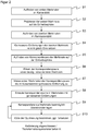
- FIG. 2 shows a flow chart of the calibration of camera 10 and laser scanner 12. This is an example. In particular, by no means all steps need to be implemented; rather, several of the steps mentioned are purely optional.
- a step S1 the camera image is examined for prominent locations, for example high-contrast locations.
- Harris corner detection and other feature detectors such as SIFT (Scale-Invariant Feature Transform), SURF (Speeded Up Robust Features), Orb (Oritented FAST and rotated LETTER) or the like.
- SIFT Scale-Invariant Feature Transform
- SURF Speeded Up Robust Features
- Orb Ortented FAST and rotated LETTER
- a step S2 the first features of the two-dimensional camera image are projected into the three-dimensional space. This is possible if the intrinsics of Camera 10 is known or determined in a corresponding calibration, ie in particular the position of the optical center within the camera 10. Without knowledge of the distance can be projected only in fixed, non-actual distances, preferably on the unit sphere.
- step S3 distinctive points are also searched for in the remission image.
- the procedure corresponds to step S1, and the result is a set of second features of the remission image.
- the second features are set to distances corresponding to the first features.
- the actual distance that the laser scanner 12 has measured would also be known for the second features.
- first and second features should be comparable, preferably both on the unit sphere.
- a step S5 now matches between the first features and the second features are searched. Correspondence pairs can be determined in a manner known per se, for example by a next-neighbor search. This step leads to a considerable improvement, because the original camera and remission pictures by no means correspond to each other visually. This is especially true at large viewing angles, such as when it is a rotating about the optical axis structure and camera 10 and laser scanner 12 each have a field of view of up to 180 ° or even more.
- a step S6 the correspondence pairs found are still filtered so that only very high-quality correspondence remains. Possible requirements are one-to-one correspondence pairs or that the features used have no further features in their respective immediate vicinity. If the features within an image are far enough apart, then the association between camera 10 and laser scanner 12 is one-to-one. The spacing of the features in the image is related to the size of the object in the calibration space, and therefore uniqueness may sometimes be forced manually by introducing larger objects into the scene 14.
- a step S7 the removal of the associated second feature of the remission image is in each case assigned from correspondence pairs to the first features of the camera image.
- the distance is known by measuring the laser scanner 12, the artificial fixing in step S4 now no longer takes place.
- the features no longer reside on the unit sphere, but according to the measurement and assignment in three-dimensional space.
- a renewed correspondence search preferably with a narrower distance criterion, is carried out on this basis. This results in an improved correspondence list and is easier to understand in a visualization than the neighborhood on the unit sphere.
- a step S9 the found correspondences in three-dimensional space are used to estimate the extrinsic transformation with a non-linear optimization method.
- An exemplary option is an iterative closest point method. But also a formulation as a linearized balance problem is conceivable, which is solved via Gauss-Newton on manifolds. This avoids problems with Euclidean angles ("gimbal lock"). Robust, correspondence-error-tolerant optimization techniques such as "Robust Kernels" or M-Estimators are also conceivable.
- a quality measure for the determined solution for example via a covariance matrix. It is also conceivable to repeat step S9 or earlier steps if the quality measure is still unsatisfactory. At least false solutions can be recognized as such and avoided in the field.
- the transformation rule obtained as a result generally comprises displacement and orientation with three degrees of freedom of translation and three degrees of freedom of rotation, ie the full mutual 6D position.
- the common origin for the transformation at the camera 10, the laser scanner 12 or at another position can be freely selected. It's also equivalent, a conversion between the two local coordinate systems of camera 10 and laser scanner 12 or to determine a global coordinate system.
- the scene 14 can already have enough contrast without any measure to find features in the camera image and the remission image and thus carry out the calibration, so that the introduction of further objects is unnecessary.
- the scene 14 is low in contrast, which is already recognized initially or possibly only due to an insufficient quality measure in step S10, simple objects such as white, black or colored cardboard can be arranged in the scene 14.
- a larger white under a black cardboard provides a reliable strong contrast.
- the camera records 10 in the IR spectrum the contrast should also exist there, but this would also be ensured by the example mentioned.
- the object (s) are visibly located in scene 14 for camera 10 and laser scanner 12. Calibration objects with special patterns and dimensions are in no case necessary, even if they would of course also be suitable with their contrasts.
Landscapes
- Engineering & Computer Science (AREA)
- Physics & Mathematics (AREA)
- General Physics & Mathematics (AREA)
- Radar, Positioning & Navigation (AREA)
- Remote Sensing (AREA)
- Computer Networks & Wireless Communication (AREA)
- Electromagnetism (AREA)
- Computer Vision & Pattern Recognition (AREA)
- Theoretical Computer Science (AREA)
- Length Measuring Devices By Optical Means (AREA)
Description
Die Erfindung betrifft ein Verfahren zur Kalibrierung einer Kamera und eines Laserscanners nach dem Oberbegriff von Anspruch 1 sowie ein entsprechendes System gemäß Anspruch 14.The invention relates to a method for calibrating a camera and a laser scanner according to the preamble of claim 1 and to a corresponding system according to
In einem Laserscanner tastet ein Abtast- oder Scanstrahl einen Bereich ab und wertet das remittierte oder reflektierte Licht aus. Um auch Informationen über Objektabstände, Konturen oder Profile zu gewinnen, wird meist nicht nur die Anwesenheit von Objekten, sondern zugleich auch deren Entfernung bestimmt. Derartige entfernungsmessende Laserscanner arbeiten nach einem Lichtlaufzeitprinzip, bei dem die Laufzeit vom Scanner in die Szenerie und zurück gemessen wird und anhand der Lichtgeschwindigkeit Entfernungsdaten berechnet werden. Zwei Arten des Lichtlaufzeitverfahrens sind weit verbreitet. Bei phasenbasierten Verfahren moduliert der Lichtsender den Scanstrahl, und es wird die Phase zwischen einer Referenz und dem empfangenen Scanstrahl ermittelt. Pulsbasierte Verfahren prägen dem Scanstrahl ein signifikantes Muster auf, beispielsweise einen schmalen Puls von nur wenigen Nanosekunden Dauer, und bestimmen den Empfangszeitpunkt dieses Musters. In einer als Pulsmittelungsverfahren bezeichneten Verallgemeinerung werden mehrere Pulse oder eine Pulsfolge ausgesandt und die empfangenen Pulse statistisch ausgewertet.In a laser scanner, a scanning beam scans an area and evaluates the reflected or reflected light. In order to obtain information about object distances, contours or profiles, not only the presence of objects but also their distance is determined. Such distance-measuring laser scanners operate according to a light transit time principle in which the transit time is measured by the scanner in the scenery and back and distance data are calculated on the basis of the speed of light. Two types of the light transit time method are widely used. In phase-based methods, the light emitter modulates the scan beam and determines the phase between a reference and the received scan beam. Pulse based methods impose a significant pattern on the scan beam, such as a narrow pulse of only a few nanoseconds duration, and determine the time of reception of that pattern. In a generalization referred to as the pulse averaging process, a plurality of pulses or a pulse sequence are emitted and the received pulses are statistically evaluated.
Bekannte Laserscanner weisen einen Drehspiegel oder ein Polygonspiegelrad auf, um periodisch eine Überwachungsebene oder ein Segment einer Überwachungsebene abzutasten. Alternativ rotiert ein aktiver Messkopf mit Lichtsender und Lichtempfänger. 3D-Laserscanner erfassen einen dreidimensionalen Raumbereich und nicht lediglich eine Fläche. Das kann durch Bewegung um eine weitere Achse realisiert werden, sei es in einer Schwenk- oder einer vollständigen Drehbewegung. In der
Kamera und Laserscanner sind Sensoren, die einander sehr gut ergänzen. Während der Laserscanner genutzt wird, um die Geometrie einer Szene abzutasten, kann die Kamera den visuellen Eindruck der Szene und damit Eigenschaften wie Beleuchtung, Materialen oder Texturen erfassen. Oftmals ist es wünschenswert, beide Sensordatenquellen zu kombinieren beziehungsweise zu fusionieren, um so die Umgebung naturgetreu zu digitalisieren. Dadurch können optischer Eindruck und Geometrie auf Computern reproduziert werden, um beispielsweise Planungsaufgaben nicht mehr vor Ort durchführen zu müssen.Camera and laser scanners are sensors that complement each other very well. While the laser scanner is used to scan the geometry of a scene, the camera can capture the visual impression of the scene and thus characteristics such as lighting, materials or textures. Often, it is desirable to combine and fuse both sensor data sources to faithfully digitize the environment. As a result, optical impression and geometry can be reproduced on computers, for example, to no longer have to carry out planning tasks on site.
Für eine korrekte Sensorfusion muss die sogenannte Extrinsik bekannt sein, also die Transformation zwischen dem optischen Zentrum des Laserscanners und der Kamera. Diese Transformation umfasst im Allgemeinen die Translation in drei Raumdimensionen und die drei Drehwinkel im Raum und hat daher sechs Freiheitsgrade. Die Bestimmung der Transformation wird extrinsische Kalibrierung genannt. Man kann dies auch als Bestimmung der Umrechnungsvorschrift zwischen den jeweiligen lokalen Koordinatensystemen beziehungsweise in ein globales Koordinatensystem beschreiben, wofür auch der Begriff Registrierung üblich ist.For a correct sensor fusion, the so-called extrinsics must be known, ie the transformation between the optical center of the laser scanner and the camera. This transformation generally involves translation in three dimensions of space and the three angles of rotation in space, and therefore has six degrees of freedom. The determination of the transformation is called extrinsic calibration. This can also be described as a determination of the conversion rule between the respective local coordinate systems or into a global coordinate system for which the term registration is also customary.
Die akademische Literatur zu extrinsischer Kalibrierung beschreibt Techniken, die von einem definiertem Kalibrierobjekt ausgehen beziehungsweise das Objekt aus mehreren Perspektiven erfassen müssen, um die Transformation zu schätzen.The academic literature on extrinsic calibration describes techniques that must start with a defined calibration object or capture the object from multiple perspectives in order to estimate the transformation.
In der
Nach
Ein konzeptionell sehr einfaches Vorgehen besteht in einem einfachen manuellen Durchprobieren der sechs Translations-und Rotationsparameter, bis die geometrischen Daten des Laserscanners und die Kameradaten optisch deckungsgleich werden. Das ist aber meist sehr ungenau und schwer zu reproduzieren, weshalb die geschätzte Transformation eine geringe Wiederholgenauigkeit hat und die Genauigkeit auch nicht quantifizierbar ist.A conceptually very simple procedure consists in a simple manual trial and error of the six translation and rotation parameters, until the geometrical data of the laser scanner and the camera data are optically congruent. However, this is usually very inaccurate and difficult to reproduce, which is why the estimated transformation has a low repeatability and the accuracy is not quantifiable.
Die
In der
Die
Die
Die
Vor diesem Hintergrund ist Aufgabe der Erfindung, die erläuterte Kalibrierung zu verbessern.Against this background, the object of the invention is to improve the explained calibration.
Diese Aufgabe wird durch ein Verfahren zur Kalibrierung einer Kamera und eines Laserscanners nach Anspruch 1 sowie ein entsprechendes System nach Anspruch 14 gelöst. Als Ausgangspunkt nimmt die Kamera ein Kamerabild einer Szenerie auf. Der Laserscanner tastet die Szenerie ab und misst die jeweilige Intensität des remittierten oder reflektierten Abtaststrahls. Im Laufe der Abtastbewegung kann so ebenfalls ein Bild zusammengesetzt werden, das als Remissionsbild bezeichnet wird. Aus einem Vergleich von Kamerabild und Remissionsbild werden dann ein Versatz beziehungsweise eine Orientierung von Kamera und Laserscanner zueinander bestimmt. Diese Bestimmung einer Transformationsvorschrift zwischen den lokalen Koordinatensystemen wird auch Registrierung oder extrinsische Kalibrierung genannt.This object is achieved by a method for calibrating a camera and a laser scanner according to claim 1 and a corresponding system according to
Die Erfindung geht nun von dem Grundgedanken aus, eine Kalibrierung trotz der nur zweidimensionalen Ausgangsdaten in Kamera- und Remissionsbild auf Basis einer Korrespondenzsuche im dreidimensionalen Raum durchzuführen. Zu dem Remissionsbild gibt es Entfernungswerte aufgrund der Messung des Laserscanners. Für das Kamerabild werden Entfernungen rekonstruiert. Damit können dann 3D-3D-Korrespondenzen gefunden werden, d.h. übereinstimmende Merkmale wie beispielsweise Pixelgruppen, Kanten oder Ecken, besondere Kontraste und dergleichen. Eine ergänzende oder vorausgehende zweidimensionale Korrespondenzsuche in 2D ist aber nicht ausgeschlossen.The invention is based on the basic idea of performing a calibration in spite of the only two-dimensional output data in the camera and remission image on the basis of a correspondence search in three-dimensional space. There are distance values for the remission image due to the measurement of the laser scanner. Distances are reconstructed for the camera image. Thus, 3D-3D correspondences can then be found, i. Matching features such as pixel groups, edges or corners, special contrasts and the like. However, a supplementary or preliminary two-dimensional correspondence search in 2D is not excluded.
Die Erfindung hat den Vorteil, dass eine einfache, weitestgehend automatische extrinsische Kalibrierung ermöglicht wird. Sie liefert reproduzierbare Ergebnisse, wobei die Lösung auch durch ein Gütemaß bewertbar ist. Ein Kalibrierobjekt ist dafür nicht erforderlich. Es genügt jeweils ein statisches Kamera- und Remissionsbild, das Verfahren kommt ohne Bewegung von Kamera und Laserscanner aus. Dabei ist wichtig darauf hinzuweisen, dass sich gerade bei großen Sichtfeldern Kamerabild und Remissionsbild erst einmal nicht besonders ähnlich sind. Das stützt die Aussagen der oben zitierten
Die Kamera ist vorzugsweise eine 2D-Kamera. Mit einer 3D-Kamera könnten Korrespondenzen direkt im dreidimensionalen Raum mit den jeweiligen Punktwolken von Kamera und Laserscanner gesucht werden.The camera is preferably a 2D camera. With a 3D camera correspondences could be searched directly in the three-dimensional space with the respective point clouds of camera and laser scanner.
Die Entfernungen in dem Kamerabild werden vorzugsweise mit Hilfe der Entfernungen des Remissionsbildes rekonstruiert. Da Kamera und Laserscanner zumindest teilweise die gleiche Szenerie aufgenommen haben, sind die Entfernungen durch die Messung mit dem Laserscanner prinzipiell bekannt. Sie können daher auf das Kamerabild übertragen werden, sobald beispielsweise im Rahmen einer Korrespondenzsuche bekannt ist, welche Entfernung zu welchem Bereich oder welchem Merkmal des Kamerabildes gehört.The distances in the camera image are preferably reconstructed using the distances of the remission image. Since the camera and laser scanner have at least partially taken up the same scene, the distances are known in principle by the measurement with the laser scanner. They can therefore be transferred to the camera image as soon as it is known, for example in the context of a correspondence search, which distance belongs to which area or feature of the camera image.
Vorzugsweise werden erste Merkmale in dem Kamerabild bestimmt und vorgegebene Entfernungen projiziert. Diese Projektion nutzt vorzugsweise die Intrinsik oder die intrinsischen Parameter der Kamera, die wiederum bekannt oder durch eine an sich bekannte intrinsische Kalibrierung bestimmt sind. Noch bevorzugter wird auf die Einheitssphäre projiziert. Die dadurch gewonnenen Entfernungen sind nicht die tatsächlichen Entfernungen, zumindest für einen ersten Schritt einer Korrespondenzsuche im dreidimensionalen Raum jedoch geeignet. Es ist nicht ausgeschlossen, anstelle der Einheitssphäre einen anderen Radius oder sogar eine andere in den dreidimensionalen Raum eingebettete Fläche zu nutzen, aber davon sind eher Verzerrungen als bessere Ergebnisse zu erwarten.Preferably, first features in the camera image are determined and predetermined distances are projected. This projection preferably uses the intrinsic or intrinsic parameters of the camera, which in turn are known or determined by a per se known intrinsic calibration. More preferably, the unit sphere is projected. The distances thus obtained are not the actual distances, but at least suitable for a first step of a correspondence search in three-dimensional space. It is not excluded to use a different radius or even another surface embedded in three-dimensional space instead of the unit sphere, but distortions rather than better results are to be expected of them.
Vorzugsweise werden zweite Merkmale in dem Remissionsbild bestimmt und auf vorgegebene Entfernungen projiziert, insbesondere auf die Einheitssphäre. Für die zweiten Merkmale sind die tatsächlichen Entfernungen aufgrund der Messung des Laserscanners bekannt. Sie werden aber hier vorerst ignoriert und auf vorgegebene Entfernungen gesetzt. Die Projektion auf die Einheitssphäre ist rechnerisch sehr einfach, weil die Entfernungen auf radialen Strahlen gemessen werden und direkt auf Eins gesetzt werden können. Wie schon bei den ersten Merkmalen kann anstelle der Einheitssphäre ein anderer Radius oder sogar eine andere Fläche verwendet werden, jedoch sollten erste und zweite Merkmale auf die gleiche Fläche projiziert werden. Die gemessenen Entfernungen werden vorzugsweise nicht verworfen, sondern für spätere Schritte gespeichert.Preferably, second features in the remission image are determined and projected to predetermined distances, in particular to the unit sphere. For the second features, the actual distances are known due to the measurement of the laser scanner. However, they are ignored here for the time being and set to predetermined distances. The projection onto the unit sphere is computationally very simple, because the distances on radial rays are measured and can be set directly on one. As with the first features, a different radius or even a different area may be used instead of the unit sphere, however, first and second features should be projected onto the same area. The measured distances are preferably not discarded, but stored for later steps.
Vorteilhafterweise wird eine erste Korrespondenzsuche im dreidimensionalen Raum zwischen den ersten Merkmalen und den zweiten Merkmalen durchgeführt. Die erste Korrespondenzsuche findet auf Basis von durch die Projektion entstandenen künstlichen Entfernungen statt, ist jedoch auch schon eine Korrespondenzsuche im dreidimensionalen Raum.Advantageously, a first correspondence search is performed in the three-dimensional space between the first features and the second features. The first correspondence search takes place on the basis of artificial distances created by the projection, but is also already a correspondence search in three-dimensional space.
Vorzugsweise werden nur eineindeutige Korrespondenzpaare zugelassen und/oder in einer Umgebung eines Korrespondenzpaares keine weiteren Merkmale vorhanden sein dürfen. Die gefundenen Korrespondenzen werden also noch gefiltert, um nur anhand von besonders zuverlässigen Korrespondenzen zu kalibrieren. Dazu sollten also Korrespondenzen in beide Richtungen erkannt sein, und um Fehlzuordnungen zu reduzieren, sollten in der direkten Umgebung keine weiteren Merkmale zu finden sein.Preferably, only one-to-one correspondence pairs are permitted and / or no further features may be present in an environment of a correspondence pair. The correspondences found are thus still filtered to calibrate only on the basis of particularly reliable correspondence. Therefore, correspondences should be recognized in both directions, and in order to reduce misallocations, no further features should be found in the direct environment.
Den ersten Merkmalen eines Korrespondenzpaares wird vorzugsweise die mit dem Laserscanner gemessene Entfernung des zugehörigen zweiten Merkmals zugewiesen, um korrigierte erste Merkmale zu gewinnen. Die Korrespondenz bedeutet, dass nach bisheriger Annahme die Kamera dasselbe Merkmal aufgenommen hat wie der Laserscanner. Daher ist die gemessene Entfernung des Laserscanners die bessere Schätzung als die festgelegte anfängliche Entfernung auf der Einheitssphäre. Die korrigierten ersten Merkmale sind folglich echte 3D-Merkmale, die nicht länger nur auf künstlichen Entfernungen basieren.The first features of a correspondence pair are preferably assigned the distance of the associated second feature measured by the laser scanner in order to obtain corrected first features. The correspondence means that the camera has assumed the same characteristics as the laser scanner. Therefore, the measured distance of the laser scanner is the better estimate than the fixed initial distance on the unit sphere. The corrected first features are therefore true 3D features that are no longer based only on artificial distances.
Vorzugsweise wird eine zweite Korrespondenzsuche im dreidimensionalen Raum zwischen den korrigierten ersten Merkmalen und den zweiten Merkmalen durchgeführt. Bei dieser erneuten Korrespondenzsuche sind die Merkmale nicht mehr auf eine vorgegebene Entfernung projiziert, sondern verwenden die gemessene Entfernung. Im Falle der zweiten Merkmale wurde diese Entfernung direkt durch den Laserscanner gemessen. Die korrigierten ersten Merkmale haben die Entfernung von dem korrespondierenden zweiten Merkmal übernommen. Es handelt sich folglich um eine echte 3D-Korrespondenzsuche, in der die Nachbarschaftsbeziehungen auch in Entfernungsrichtung voll zum Tragen kommen.Preferably, a second correspondence search is performed in the three-dimensional space between the corrected first features and the second features. In this re-correspondence search, the features are no longer projected to a given distance, but use the measured distance. In the case of the second features, this distance was measured directly by the laser scanner. The corrected first features have taken the distance from the corresponding second feature. It is therefore a true 3D correspondence search, in which the neighborhood relationships also come in the distance direction to full effect.
Die ersten Merkmale und die zweiten Merkmale der gefundenen Korrespondenzpaare werden vorzugsweise durch eine insbesondere nichtlineare Optimierung von Versatz und/oder Orientierung bestmöglich übereinander gelegt. Dafür stehen mächtige Algorithmen zur Verfügung, und Versatz und Orientierung bei optimaler Übereinstimmung sind die gesuchten Transformationsparameter für die Kalibrierung beziehungsweise Sensorfusion.The first features and the second features of the correspondence pairs found are preferably stacked as best as possible by a particularly non-linear optimization of offset and / or orientation. Powerful algorithms are available for this, and misalignment and orientation with optimal match are the sought-after transformation parameters for calibration or sensor fusion.
Vorteilhafterweise wird eine Güte der Übereinstimmung berechnet. Die Optimierungsverfahren liefern eine derartige Güte meist mit, etwa in Form einer Kovarianzmatrix. Sie kann auch vorgegeben und beispielsweise als Abbruchkriterium der nichtlinearen Optimierung genutzt werden. Damit ist bekannt, wie groß beispielsweise der kumulierte Restfehler der übereinander gelegten Merkmale noch ist. Bewertet werden kann auch, wie gut die zugrunde gelegten Korrespondenzen waren.Advantageously, a quality of the match is calculated. The optimization methods usually provide such a quality, for example in the form of a covariance matrix. It can also be specified and, for example, as a termination criterion for nonlinear optimization be used. It is thus known how large, for example, the accumulated residual error of the superimposed features is still. It is also possible to assess how good the underlying correspondence was.
Der Laserscanner ist bevorzugt ein 3D-Laserscanner. Der Laserscanner tastet also nicht nur durch eine Schwenk- oder Rotationsbewegung einer Ebene ab, sondern variiert auch den Nickwinkel. Die konkrete Raumkurve der Abtastbewegung ist für die Erfindung nicht von Belang. Jedenfalls wird auf diese Weise ein 2D-Remissionsbild erfasst, das mit dem 2D-Kamerabild besonders gut vergleichbar ist.The laser scanner is preferably a 3D laser scanner. The laser scanner thus not only scans through a swivel or rotation movement of a plane, but also varies the pitch angle. The concrete space curve of the scanning movement is not relevant to the invention. In any case, a 2D remission image is captured in this way, which is particularly well comparable to the 2D camera image.
Die Szenerie für die Kalibrierung wird bevorzugt belassen, wie sie ist. Die Kalibrierung erfolgt also anhand natürlicher Merkmale, die in der Szenerie von Anfang an vorhanden sind. Das vereinfacht das Verfahren für den Anwender weiter. Insbesondere muss kein Kalibrierobjekt in der Szenerie angeordnet werden, und dementsprechend sind auch keine genauen Spezifikationen hinsichtlich Abmessungen und Form einzuhalten oder für das Verfahren vorzugeben.The scenery for the calibration is preferably left as it is. The calibration is thus based on natural features that are present in the scenery from the beginning. This further simplifies the procedure for the user. In particular, no calibration object needs to be placed in the scene, and accordingly, no exact specifications in terms of dimensions and shape are to be kept or specified for the process.
Für die Kalibrierung wird alternativ mindestens ein Gegenstand mit einem gewünschten Remissionsverhalten in der Szenerie angeordnet, um den Kontrast zu erhöhen. Damit ist immer noch kein Kalibrierobjekt mit speziellen Eigenschaften oder Mustern gemeint. Es geht lediglich darum, in einer strukturlosen Szenerie, etwa einem leeren Raum mit weißen Wänden, für ausreichend Kontrast und damit potentielle Merkmale zu sorgen, mit denen Korrespondenzen gebildet werden können. Dafür genügen einfache und überall verfügbare Alltagsgegenstände, beispielsweise Pappe oder Fotokarton. Weiterhin müssen weder besondere Abmessungen eingehalten noch die Kalibrierung damit parametriert werden.For the calibration, alternatively, at least one object with a desired reflectance behavior in the scene is arranged to increase the contrast. This still does not mean a calibration object with special properties or patterns. The point is, in a structureless scene, such as an empty room with white walls, to provide sufficient contrast and thus potential features with which correspondences can be formed. Simple and universally available everyday items, such as cardboard or photo carton, are all you need. Furthermore, neither special dimensions must be maintained nor the calibration parameterized.
Das erfindungsgemäße System weist die Kamera, den Laserscanner sowie eine Auswertungseinheit auf, in der das Verfahren zur Kalibrierung abläuft. Die Auswertungseinheit kann in beliebiger Hardware realisiert und auch beliebig auf Kamera, Laserscanner und/oder ein speziell dafür angeschlossenes oder universelles externes Gerät wie ein Notebook oder ein Smartphone verteilt sein. Es bedarf lediglich einer gewissen Rechenleistung sowie des Zugriffs auf die Rohdaten von Kamera und Laserscanner. Die Erfindung wird nachstehend auch hinsichtlich weiterer Merkmale und Vorteile beispielhaft anhand von Ausführungsformen und unter Bezug auf die beigefügte Zeichnung näher erläutert. Die Abbildungen der Zeichnung zeigen in:
- Fig. 1
- eine schematische Darstellung einer Anordnung einer Kamera, eines Laserscanners und einer Auswertungseinheit zur Kalibrierung für eine Sensorfusion; und
- Fig. 2
- ein beispielhaftes Ablaufschema einer Kalibrierung von Kamera und Laserscanner für deren Sensorfusion.
- Fig. 1
- a schematic representation of an arrangement of a camera, a laser scanner and an evaluation unit for calibration for a sensor fusion; and
- Fig. 2
- an exemplary flowchart of a calibration of camera and laser scanner for their sensor fusion.
Das Funktionsprinzip des Laserscanner 12 ist an sich bekannt und einleitend beschrieben. Für die Erfindung ist nicht relevant, welcher konkrete Aufbau für den Laserscanner 12 gewählt wird. Allerdings ist der Laserscanner 12 vorzugsweise ein 3D-Laserscanner, um einen zu dem Sichtfeld der Kamera 10 vergleichbaren Erfassungsbereich zu erhalten.The operating principle of the
Der Laserscanner 12 erfasst ebenfalls die Szenerie 14. Dabei gibt es einen Überlapp zwischen Sichtfeld der Kamera 10 und Erfassungsbereich des Laserscanners 14, der vorzugsweise groß oder sogar vollständig ist, denn nur dort können die Daten für eine Kalibrierung genutzt werden und später im Betrieb diversitär zu einer Fusion beitragen. In nicht überlappenden Bereichen ist aber auch eine Datenfusion in dem Sinne möglich, dass an den Rändern zumindest die Kamera 10 oder der Laserscanner 12 noch Daten beiträgt. Typischerweise hat der Laserscanner 12 den breiteren Erfassungsbereich, aber die Kamera 10 kann durch Panoramaoptiken und dergleichen ebenfalls ein breites Sichtfeld erfassen.The
Der Laserscanner 12 misst Entfernungen wie einleitend erläutert. Zugleich ist der Laserscanner 12 aber auch in der Lage, neben der Distanzmessung auch die Intensität des wieder empfangenen Abtaststrahls zu bestimmen. Dadurch lässt sich nach und nach im Verlauf der Abtastbewegung ein Remissionsbild aufbauen. Da die jeweiligen S4 Winkelstellungen bekannt sind, können die gemessenen Intensitäten als Pixel des Remissionsbildes an die richtige Stelle gesetzt werden. Wenn der Laserscanner 12 nicht nur eine Ebene abtastet, sondern als 3D-Laserscanner auch den Nickwinkel variiert, ist das Remissionsbild ein zweidimensionales Bild. Die Aufnahme von Kamera- und Remissionsbild erfolgt für die nachfolgend erläuterte Kalibrierung möglichst gleichzeitig, jedenfalls so, dass die Szenerie als quasi-statisch betrachtet werden kann, weil sonst Kalibrationsfehler resultieren.The
Über eine Kameraschnittstelle 16 ist die Kamera 10 und über eine Laserscannerschnittstelle 18 der Laserscanner 12 an eine Auswertungseinheit 20 angeschlossen. Dabei kann es sich um eine übergeordnete Steuerung, ein Notebook oder dergleichen handeln. Die hier externe Auswertungseinheit 20 kann alternativ zumindest teilweise intern in Kamera 10 und/oder Laserscanner 12 vorgesehen sein.Via a
Die Auswertungseinheit 20 empfängt das Kamerabild, das Remissionsbild sowie die 3D-Punktwolke der von dem Laserscanner 12 gemessenen Entfernungen oder entsprechende Rohdaten in beliebiger Verarbeitungsstufe, um diese Daten selbst zu gewinnen. Damit erfolgt dann eine Kalibrierung von Kamera 10 und Laserscanner 12 wie nachfolgend beschrieben. Im Betrieb ist somit bekannt, wie die Daten der Kamera 10 und des Laserscanners 12 unter Berücksichtigung von gegenseitigem Versatz und/oder Verkippung miteinander fusioniert werden können.The
In einem Schritt S1 wird das Kamerabild auf markante Stellen untersucht, beispielsweise Stellen mit hohem Kontrast. Einige bekannte Algorithmen dafür sind Harris-Corner-Detektion und weitere Feature-Detektoren wie SIFT (Scale-Invariant Feature Transform), SURF (Speeded Up Robust Features), ORB (Oritented FAST and rotated BRIEF) oder Ähnliches. Dadurch kann eine Menge von ersten Merkmalen des Kamerabildes bestimmt werden, wobei mindestens drei Elemente für das weitere Verfahren erforderlich sind.In a step S1, the camera image is examined for prominent locations, for example high-contrast locations. Some known algorithms for this are Harris corner detection and other feature detectors such as SIFT (Scale-Invariant Feature Transform), SURF (Speeded Up Robust Features), Orb (Oritented FAST and rotated LETTER) or the like. As a result, a set of first characteristics of the camera image can be determined, wherein at least three elements are required for the further process.
In einem Schritt S2 werden die ersten Merkmale aus dem zweidimensionalen Kamerabild in den dreidimensionalen Raum projiziert. Das ist möglich, wenn die Intrinsik der Kamera 10 bekannt oder in einer entsprechenden Kalibration bestimmt ist, also insbesondere die Lage des optischen Zentrums innerhalb der Kamera 10. Ohne Kenntnis der Entfernung kann aber nur in festgelegte, nicht tatsächliche Entfernungen projiziert werden, vorzugsweise auf die Einheitssphäre.In a step S2, the first features of the two-dimensional camera image are projected into the three-dimensional space. This is possible if the intrinsics of
In einem Schritt S3 werden auch in dem Remissionsbild markante Stellen gesucht. Das Vorgehen entspricht dem Schritt S1, und das Ergebnis ist eine Menge von zweiten Merkmalen des Remissionsbildes.In step S3, distinctive points are also searched for in the remission image. The procedure corresponds to step S1, and the result is a set of second features of the remission image.
In einem Schritt S4 werden die zweiten Merkmale auf Entfernungen entsprechend den ersten Merkmalen gesetzt. An sich wäre für die zweiten Merkmale auch die tatsächliche Entfernung bekannt, die der Laserscanner 12 gemessen hat. Für das weitere Verfahren sollen aber erste und zweite Merkmale vergleichbar sein, vorzugsweise beide auf der Einheitssphäre.In a step S4, the second features are set to distances corresponding to the first features. As such, the actual distance that the
In einem Schritt S5 werden nun Übereinstimmungen zwischen den ersten Merkmalen und den zweiten Merkmalen gesucht. Korrespondenzpaare können in an sich bekannter Weise beispielsweise durch eine Nächste-Nachbarn-Suche bestimmt werden. Dieser Schritt führt zu einer erheblichen Verbesserung, weil die ursprünglichen Kamera- und Remissionsbilder einander rein visuell keineswegs entsprechen. Das gilt vor allem bei großen Sichtwinkeln, etwa wenn es sich um einen um die optische Achse rotierenden Aufbau handelt und Kamera 10 und Laserscanner 12 jeweils über einen Sichtbereich von bis zu 180° oder noch mehr aufweisen.In a step S5 now matches between the first features and the second features are searched. Correspondence pairs can be determined in a manner known per se, for example by a next-neighbor search. This step leads to a considerable improvement, because the original camera and remission pictures by no means correspond to each other visually. This is especially true at large viewing angles, such as when it is a rotating about the optical axis structure and
In einem Schritt S6 werden die gefundenen Korrespondenzpaare noch gefiltert, damit nur besonders hochwertige Korrespondenzen verbleiben. Mögliche Forderungen sind eineindeutige Korrespondenzpaare oder dass die verwendeten Merkmale in ihrer jeweiligen näheren Nachbarschaft keine weiteren Merkmale aufweisen. Sind die Merkmale innerhalb eines Bildes weit genug voneinander entfernt, dann ist die Zuordnung zwischen Kamera 10 und Laserscanner 12 eineindeutig. Der Abstand der Merkmale im Bild hängt mit der Größe des Objektes im Kalibrierraum zusammen, und deshalb kann unter Umständen Eineindeutigkeit manuell forciert werden, indem größere Objekte in die Szenerie 14 eingebracht werden.In a step S6, the correspondence pairs found are still filtered so that only very high-quality correspondence remains. Possible requirements are one-to-one correspondence pairs or that the features used have no further features in their respective immediate vicinity. If the features within an image are far enough apart, then the association between
In einem Schritt S7 wird jeweils aus Korrespondenzpaaren den ersten Merkmalen des Kamerabildes die Entfernung des zugehörigen zweiten Merkmals des Remissionsbildes zugewiesen. Für das zweite Merkmal ist die Entfernung durch Messung des Laserscanners 12 bekannt, das künstliche Festlegen im Schritt S4 findet jetzt nicht mehr statt. Dadurch liegen die Merkmale jetzt nicht mehr auf der Einheitssphäre, sondern entsprechend der Messung und Zuweisung im dreidimensionalen Raum.In a step S7, the removal of the associated second feature of the remission image is in each case assigned from correspondence pairs to the first features of the camera image. For the second feature, the distance is known by measuring the
In einem Schritt S8 wird auf dieser Basis eine erneute Korrespondenzsuche vorzugsweise mit einem engeren Distanzkriterium durchgeführt. Dies ergibt eine verbesserte Korrespondenzliste und ist auch in einer Visualisierung leichter nachzuvollziehen als die Nachbarschaft auf der Einheitssphäre.In a step S8, a renewed correspondence search, preferably with a narrower distance criterion, is carried out on this basis. This results in an improved correspondence list and is easier to understand in a visualization than the neighborhood on the unit sphere.
In einem Schritt S9 werden die gefundenen Korrespondenzen im dreidimensionalen Raum benutzt, um die extrinsische Transformation mit einem nicht-linearen Optimierungsverfahren zu schätzen. Eine beispielhafte Möglichkeit ist ein Iterative-Closest-Point-Verfahren. Aber auch eine Formulierung als linearisiertes Ausgleichsproblem ist denkbar, das über Gauß-Newton auf Mannigfaltigkeiten gelöst wird. Dadurch lassen sich Probleme mit euklidischen Winkeln vermeiden ("Gimbal Lock"). Robuste, korrespondenzfehlertolerante Optimierungstechniken wie "Robust Kernels" oder M-Estimatoren sind ebenfalls denkbar.In a step S9, the found correspondences in three-dimensional space are used to estimate the extrinsic transformation with a non-linear optimization method. An exemplary option is an iterative closest point method. But also a formulation as a linearized balance problem is conceivable, which is solved via Gauss-Newton on manifolds. This avoids problems with Euclidean angles ("gimbal lock"). Robust, correspondence-error-tolerant optimization techniques such as "Robust Kernels" or M-Estimators are also conceivable.
In einem Schritt S10 kann anhand der Korrespondenzen und der Rückprojektion mathematisch auch ein Gütemaß für die ermittelte Lösung abgeleitet werden, etwa über eine Kovarianzmatrix. Es ist auch denkbar, den Schritt S9 oder frühere Schritte zu wiederholen, wenn das Gütemaß noch unbefriedigend ist. Zumindest können falsche Lösungen als solche erkannt und im Einsatz vermieden werden.In a step S10, based on the correspondences and the backprojection, it is also possible mathematically to derive a quality measure for the determined solution, for example via a covariance matrix. It is also conceivable to repeat step S9 or earlier steps if the quality measure is still unsatisfactory. At least false solutions can be recognized as such and avoided in the field.
Die als Ergebnis gewonnene Transformationsvorschrift umfasst allgemein Versatz und Orientierung mit drei Freiheitsgraden der Translation und drei Freiheitsgraden der Rotation, also die volle gegenseitige 6D-Lage. Es kann aber auch Rahmenbedingungen geben, welche Freiheitsgrade von vorneherein festlegen oder uninteressant machen, wo es dann ausreicht, nur einen entsprechenden Teil der Transformationsvorschrift in weniger Dimensionen zu bestimmen. Ob der gemeinsame Ursprung für die Transformation bei der Kamera 10, dem Laserscanner 12 oder an einer anderen Position liegt, kann frei gewählt werden. Es ist auch äquivalent, eine Umrechnung zwischen den zwei lokalen Koordinatensystemen von Kamera 10 und Laserscanner 12 oder in ein globales Koordinatensystem zu bestimmen.The transformation rule obtained as a result generally comprises displacement and orientation with three degrees of freedom of translation and three degrees of freedom of rotation, ie the full mutual 6D position. However, there may also be framework conditions which define degrees of freedom from the outset or make them uninteresting, where it is then sufficient to determine only a corresponding part of the transformation rule in fewer dimensions. Whether the common origin for the transformation at the
Die Szenerie 14 kann schon ohne jegliche Maßnahme genug Kontrast aufweisen, um Merkmale in Kamerabild und Remissionsbild zu finden und damit die Kalibrierung auszuführen, so dass das Einbringen von weiteren Objekten unnötig ist. Falls aber die Szenerie 14 kontrastarm ist, was schon anfänglich oder möglicherweise erst an einem unzureichenden Gütemaß in Schritt S10 erkannt wird, können einfache Objekte wie etwa weiße, schwarze oder farbige Pappen in der Szenerie 14 angeordnet werden. Eine größere weiße unter einer schwarzen Pappe bietet einen verlässlichen starken Kontrast. Falls die Kamera 10 im IR-Spektrum aufzeichnet, sollte der Kontrast auch dort bestehen, was aber durch das genannte Beispiel auch gewährleistet wäre. Der oder die Objekte werden für Kamera 10 und Laserscanner 12 sichtbar in der Szenerie 14 angeordnet. Kalibrierobjekte mit besonderen Mustern und Abmessungen sind in keinem Fall notwendig, auch wenn sie sich mit ihren Kontrasten natürlich ebenfalls eignen würden.The
Claims (14)
- A method of calibrating a camera (10) and a laser scanner (12) for their sensor fusion, wherein the camera (10) records a camera image of a scene (14) and the laser scanner (12) at least partly scans the scene (14) with a scanning beam and records a remission image from the respective angular position of the scanning beam and from the intensity determined at the angular position of the scanning beam remitted from the scene (14), wherein an offset and/or a relative orientation between the camera (10) and the laser scanner (12) is determined from a comparison of the camera image and the remission image, wherein distances are determined by the laser scanner (12) with respect to the remission image,
characterized in that, for the comparison, despite the original data of the camera image and the remission image being only two-dimensional, a correspondence search for 3D-3D-corresponding features in the camera image and in the remission image is carried out in three-dimensional space by reconstructing distances with respect to the camera image. - The method in accordance with claim 1,
wherein the distances in the camera image are reconstructed with the aid of the remission image. - The method in accordance with claim 1 or 2,
wherein first features are determined in the camera image and are projected onto predefined distances, in particular onto the unit sphere. - The method in accordance with any of the preceding claims,
wherein second features are determined in the remission image and are projected onto predefined distances, in particular onto the unit sphere. - The method in accordance with claims 3 and 4,
wherein a first correspondence search is carried out in three-dimensional space between the first features and the second features. - The method in accordance with any of the preceding claims,
wherein only one-to-one correspondence pairs are permitted and/or no further features may be present in the surroundings of a correspondence pair. - The method in accordance with claims 5 or 6,
wherein the distance of the associated second feature measured by the laser scanner (12) is assigned to the first features of a correspondence pair to acquire corrected first features. - The method in accordance with claim 7,
wherein a second correspondence search is carried out in three-dimensional space between the corrected first features and the second features. - The method in accordance with any of the preceding claims,
wherein the corresponding features are placed over one another as best as possible by an optimization of offset and/or orientation, in particular a nonlinear optimization. - The method in accordance with claim 10,
wherein a quality of the optimization is calculated. - The method in accordance with any of the preceding claims,
wherein the laser scanner (12) is a 3D laser scanner. - The method in accordance with any of the preceding claims,
wherein the scene for the calibration is left as it is, in particular no calibration object is arranged in the scene. - The method in accordance with claims 1 to 11,
wherein at least one object having a desired remission behavior is arranged in the scene (14) for the calibration in order to increase the contrast. - A system comprising a camera (10) and a laser scanner (12) as well as an evaluation unit (20) that is configured to calibrate the camera (10) and the laser scanner (12) by using a method according to any of the preceding claims.
Applications Claiming Priority (1)
| Application Number | Priority Date | Filing Date | Title |
|---|---|---|---|
| DE102017109039.8A DE102017109039A1 (en) | 2017-04-27 | 2017-04-27 | Method for calibrating a camera and a laser scanner |
Publications (2)
| Publication Number | Publication Date |
|---|---|
| EP3396409A1 EP3396409A1 (en) | 2018-10-31 |
| EP3396409B1 true EP3396409B1 (en) | 2019-11-27 |
Family
ID=61972003
Family Applications (1)
| Application Number | Title | Priority Date | Filing Date |
|---|---|---|---|
| EP18166937.5A Active EP3396409B1 (en) | 2017-04-27 | 2018-04-12 | Method for calibrating a camera and a laser scanner |
Country Status (3)
| Country | Link |
|---|---|
| US (1) | US10643349B2 (en) |
| EP (1) | EP3396409B1 (en) |
| DE (1) | DE102017109039A1 (en) |
Families Citing this family (12)
| Publication number | Priority date | Publication date | Assignee | Title |
|---|---|---|---|---|
| CN109658457B (en) * | 2018-11-02 | 2021-09-17 | 浙江大学 | Method for calibrating arbitrary relative pose relationship between laser and camera |
| CN109901142B (en) * | 2019-02-28 | 2021-03-30 | 东软睿驰汽车技术(沈阳)有限公司 | Calibration method and device |
| CN111754578B (en) * | 2019-03-26 | 2023-09-19 | 舜宇光学(浙江)研究院有限公司 | Combined calibration method for laser radar and camera, system and electronic equipment thereof |
| CN110244282B (en) * | 2019-06-10 | 2021-06-15 | 宁波智能装备研究院有限公司 | Multi-camera system and laser radar combined system and combined calibration method thereof |
| FR3098929B1 (en) | 2019-07-16 | 2021-06-18 | Yellowscan | Method for determining extraneous calibration parameters of a measuring system |
| CN110322519B (en) * | 2019-07-18 | 2023-03-31 | 天津大学 | Calibration device and calibration method for combined calibration of laser radar and camera |
| JP7103324B2 (en) * | 2019-09-10 | 2022-07-20 | 株式会社デンソー | Anomaly detection device for object recognition and anomaly detection program for object recognition |
| CN110619666B (en) * | 2019-09-20 | 2022-05-27 | 阿波罗智能技术(北京)有限公司 | Method and device for calibrating camera |
| DE102019129986A1 (en) | 2019-11-07 | 2021-05-12 | Sick Ag | Optoelectronic sensor and method for detecting objects |
| CN111640158B (en) * | 2020-06-11 | 2023-11-10 | 武汉斌果科技有限公司 | End-to-end camera and laser radar external parameter calibration method based on corresponding mask |
| DE102021202993A1 (en) | 2021-03-26 | 2022-09-29 | Robert Bosch Gesellschaft mit beschränkter Haftung | Method for determining a calibration quality of an optical sensor |
| CN113269673B (en) * | 2021-04-26 | 2023-04-07 | 西安交通大学 | Three-dimensional point cloud splicing method based on standard ball frame |
Family Cites Families (13)
| Publication number | Priority date | Publication date | Assignee | Title |
|---|---|---|---|---|
| DE102004033114A1 (en) * | 2004-07-08 | 2006-01-26 | Ibeo Automobile Sensor Gmbh | Method for calibrating a distance image sensor |
| US7880865B2 (en) | 2007-02-28 | 2011-02-01 | Denso Wave Incorporated | Laser radar apparatus for three-dimensional detection of objects |
| DE502007002821D1 (en) * | 2007-08-10 | 2010-03-25 | Sick Ag | Recording of equalized images of moving objects with uniform resolution by line sensor |
| US8044991B2 (en) * | 2007-09-28 | 2011-10-25 | The Boeing Company | Local positioning system and method |
| DE102008032216A1 (en) | 2008-07-09 | 2010-01-14 | Sick Ag | Device for detecting the presence of an object in space |
| US8290305B2 (en) | 2009-02-13 | 2012-10-16 | Harris Corporation | Registration of 3D point cloud data to 2D electro-optical image data |
| DE102011056948A1 (en) * | 2011-12-22 | 2013-06-27 | Jenoptik Robot Gmbh | Method for calibrating a camera to a position sensor |
| AU2013248937B2 (en) | 2012-04-17 | 2016-10-06 | Commonwealth Scientific And Industrial Research Organisation | Three dimensional scanning beam and imaging system |
| GB2507560A (en) * | 2012-11-05 | 2014-05-07 | Univ Oxford | Extrinsic calibration of mobile camera and lidar |
| EP2827099A1 (en) * | 2013-07-16 | 2015-01-21 | Leica Geosystems AG | Laser tracker with target searching functionality |
| DE102013114821B3 (en) * | 2013-12-23 | 2014-10-23 | Jenoptik Robot Gmbh | Method for aligning a laser scanner to a roadway |
| JP2016057108A (en) * | 2014-09-08 | 2016-04-21 | 株式会社トプコン | Arithmetic device, arithmetic system, arithmetic method and program |
| DE102015118874A1 (en) * | 2015-11-04 | 2017-05-04 | Valeo Schalter Und Sensoren Gmbh | Method for operating a sensor system of a motor vehicle, driver assistance system and system for calibrating a sensor system of a motor vehicle |
-
2017
- 2017-04-27 DE DE102017109039.8A patent/DE102017109039A1/en not_active Withdrawn
-
2018
- 2018-04-11 US US15/950,589 patent/US10643349B2/en active Active
- 2018-04-12 EP EP18166937.5A patent/EP3396409B1/en active Active
Non-Patent Citations (1)
| Title |
|---|
| None * |
Also Published As
| Publication number | Publication date |
|---|---|
| DE102017109039A1 (en) | 2018-10-31 |
| US20180315214A1 (en) | 2018-11-01 |
| US10643349B2 (en) | 2020-05-05 |
| EP3396409A1 (en) | 2018-10-31 |
Similar Documents
| Publication | Publication Date | Title |
|---|---|---|
| EP3396409B1 (en) | Method for calibrating a camera and a laser scanner | |
| EP3034995B1 (en) | Method for determining a position and orientation offset of a geodetic surveying device and corresponding measuring device | |
| DE102012112321B4 (en) | Device for optically scanning and measuring an environment | |
| DE102012112322B4 (en) | Method for optically scanning and measuring an environment | |
| DE102009015922B4 (en) | Method for optically scanning and measuring a scene | |
| DE10081029B4 (en) | Image editing to prepare a textual analysis | |
| DE69826753T2 (en) | Optical profile sensor | |
| DE102013017500B3 (en) | Method and apparatus for optically scanning and measuring a scene | |
| DE112010004767T5 (en) | Point cloud data processing device, point cloud data processing method and point cloud data processing program | |
| DE102006055758B4 (en) | Method for calibrating cameras and projectors | |
| DE19727281C1 (en) | Geometric calibration device for CCD camera | |
| EP2728374B1 (en) | Invention relating to the hand-eye calibration of cameras, in particular depth image cameras | |
| EP3819671B1 (en) | Optoelectronic sensor and method for detecting objects | |
| DE102017118767B4 (en) | Method and device for determining dimensional and / or geometric properties of a measurement object | |
| DE102015122842A1 (en) | Calibration plate for calibrating a 3D measuring device and method therefor | |
| EP2880853B1 (en) | Apparatus and method for determining the distinct location of an image-recording camera | |
| DE102009015921A1 (en) | Method for optically scanning and measuring an environment | |
| EP1395852A1 (en) | Method for preparing image information | |
| DE102014104712A1 (en) | Registration of a clustered scene with visualized clusters | |
| DE19525561C2 (en) | 3D measuring device | |
| EP1460454A2 (en) | Method for combined processing of high resolution images and video images | |
| EP3711289A1 (en) | Method for automatically restoring a calibrated state of a projection system | |
| DE102011017707A1 (en) | Method for detecting object e.g. concrete post in vicinity of camera for monitoring rear side region of vehicle, involves reading images captured by cameras after partially illuminating with illumination patterns | |
| DE102015106836A1 (en) | Method for controlling a 3D measuring device by means of instantaneous movement and device for this purpose | |
| CH702255A1 (en) | Three dimensional table scanner for three dimensional detection of objects, has cameras and light sources are arranged relative to object by holding devices, and processing device is operatively connected with cameras |
Legal Events
| Date | Code | Title | Description |
|---|---|---|---|
| PUAI | Public reference made under article 153(3) epc to a published international application that has entered the european phase |
Free format text: ORIGINAL CODE: 0009012 |
|
| STAA | Information on the status of an ep patent application or granted ep patent |
Free format text: STATUS: THE APPLICATION HAS BEEN PUBLISHED |
|
| AK | Designated contracting states |
Kind code of ref document: A1 Designated state(s): AL AT BE BG CH CY CZ DE DK EE ES FI FR GB GR HR HU IE IS IT LI LT LU LV MC MK MT NL NO PL PT RO RS SE SI SK SM TR |
|
| AX | Request for extension of the european patent |
Extension state: BA ME |
|
| STAA | Information on the status of an ep patent application or granted ep patent |
Free format text: STATUS: REQUEST FOR EXAMINATION WAS MADE |
|
| 17P | Request for examination filed |
Effective date: 20190219 |
|
| RBV | Designated contracting states (corrected) |
Designated state(s): AL AT BE BG CH CY CZ DE DK EE ES FI FR GB GR HR HU IE IS IT LI LT LU LV MC MK MT NL NO PL PT RO RS SE SI SK SM TR |
|
| STAA | Information on the status of an ep patent application or granted ep patent |
Free format text: STATUS: EXAMINATION IS IN PROGRESS |
|
| 17Q | First examination report despatched |
Effective date: 20190517 |
|
| REG | Reference to a national code |
Ref country code: DE Ref legal event code: R079 Ref document number: 502018000418 Country of ref document: DE Free format text: PREVIOUS MAIN CLASS: G01S0017020000 Ipc: G06T0007730000 |
|
| GRAP | Despatch of communication of intention to grant a patent |
Free format text: ORIGINAL CODE: EPIDOSNIGR1 |
|
| STAA | Information on the status of an ep patent application or granted ep patent |
Free format text: STATUS: GRANT OF PATENT IS INTENDED |
|
| RIC1 | Information provided on ipc code assigned before grant |
Ipc: G01S 17/02 20060101ALI20190627BHEP Ipc: G01S 7/497 20060101ALI20190627BHEP Ipc: G01S 17/89 20060101ALI20190627BHEP Ipc: G01S 7/48 20060101ALI20190627BHEP Ipc: G06T 7/80 20170101ALI20190627BHEP Ipc: G06T 7/73 20170101AFI20190627BHEP Ipc: G01S 17/42 20060101ALI20190627BHEP |
|
| INTG | Intention to grant announced |
Effective date: 20190718 |
|
| GRAS | Grant fee paid |
Free format text: ORIGINAL CODE: EPIDOSNIGR3 |
|
| GRAA | (expected) grant |
Free format text: ORIGINAL CODE: 0009210 |
|
| STAA | Information on the status of an ep patent application or granted ep patent |
Free format text: STATUS: THE PATENT HAS BEEN GRANTED |
|
| AK | Designated contracting states |
Kind code of ref document: B1 Designated state(s): AL AT BE BG CH CY CZ DE DK EE ES FI FR GB GR HR HU IE IS IT LI LT LU LV MC MK MT NL NO PL PT RO RS SE SI SK SM TR |
|
| REG | Reference to a national code |
Ref country code: GB Ref legal event code: FG4D Free format text: NOT ENGLISH |
|
| REG | Reference to a national code |
Ref country code: CH Ref legal event code: EP |
|
| REG | Reference to a national code |
Ref country code: DE Ref legal event code: R096 Ref document number: 502018000418 Country of ref document: DE |
|
| REG | Reference to a national code |
Ref country code: AT Ref legal event code: REF Ref document number: 1207556 Country of ref document: AT Kind code of ref document: T Effective date: 20191215 |
|
| REG | Reference to a national code |
Ref country code: IE Ref legal event code: FG4D Free format text: LANGUAGE OF EP DOCUMENT: GERMAN |
|
| RAP2 | Party data changed (patent owner data changed or rights of a patent transferred) |
Owner name: SICK AG |
|
| REG | Reference to a national code |
Ref country code: SE Ref legal event code: TRGR |
|
| REG | Reference to a national code |
Ref country code: NL Ref legal event code: MP Effective date: 20191127 |
|
| REG | Reference to a national code |
Ref country code: LT Ref legal event code: MG4D |
|
| PG25 | Lapsed in a contracting state [announced via postgrant information from national office to epo] |
Ref country code: LV Free format text: LAPSE BECAUSE OF FAILURE TO SUBMIT A TRANSLATION OF THE DESCRIPTION OR TO PAY THE FEE WITHIN THE PRESCRIBED TIME-LIMIT Effective date: 20191127 Ref country code: LT Free format text: LAPSE BECAUSE OF FAILURE TO SUBMIT A TRANSLATION OF THE DESCRIPTION OR TO PAY THE FEE WITHIN THE PRESCRIBED TIME-LIMIT Effective date: 20191127 Ref country code: GR Free format text: LAPSE BECAUSE OF FAILURE TO SUBMIT A TRANSLATION OF THE DESCRIPTION OR TO PAY THE FEE WITHIN THE PRESCRIBED TIME-LIMIT Effective date: 20200228 Ref country code: NL Free format text: LAPSE BECAUSE OF FAILURE TO SUBMIT A TRANSLATION OF THE DESCRIPTION OR TO PAY THE FEE WITHIN THE PRESCRIBED TIME-LIMIT Effective date: 20191127 Ref country code: NO Free format text: LAPSE BECAUSE OF FAILURE TO SUBMIT A TRANSLATION OF THE DESCRIPTION OR TO PAY THE FEE WITHIN THE PRESCRIBED TIME-LIMIT Effective date: 20200227 Ref country code: BG Free format text: LAPSE BECAUSE OF FAILURE TO SUBMIT A TRANSLATION OF THE DESCRIPTION OR TO PAY THE FEE WITHIN THE PRESCRIBED TIME-LIMIT Effective date: 20200227 Ref country code: FI Free format text: LAPSE BECAUSE OF FAILURE TO SUBMIT A TRANSLATION OF THE DESCRIPTION OR TO PAY THE FEE WITHIN THE PRESCRIBED TIME-LIMIT Effective date: 20191127 |
|
| PG25 | Lapsed in a contracting state [announced via postgrant information from national office to epo] |
Ref country code: RS Free format text: LAPSE BECAUSE OF FAILURE TO SUBMIT A TRANSLATION OF THE DESCRIPTION OR TO PAY THE FEE WITHIN THE PRESCRIBED TIME-LIMIT Effective date: 20191127 Ref country code: HR Free format text: LAPSE BECAUSE OF FAILURE TO SUBMIT A TRANSLATION OF THE DESCRIPTION OR TO PAY THE FEE WITHIN THE PRESCRIBED TIME-LIMIT Effective date: 20191127 Ref country code: IS Free format text: LAPSE BECAUSE OF FAILURE TO SUBMIT A TRANSLATION OF THE DESCRIPTION OR TO PAY THE FEE WITHIN THE PRESCRIBED TIME-LIMIT Effective date: 20200327 |
|
| PG25 | Lapsed in a contracting state [announced via postgrant information from national office to epo] |
Ref country code: AL Free format text: LAPSE BECAUSE OF FAILURE TO SUBMIT A TRANSLATION OF THE DESCRIPTION OR TO PAY THE FEE WITHIN THE PRESCRIBED TIME-LIMIT Effective date: 20191127 |
|
| PG25 | Lapsed in a contracting state [announced via postgrant information from national office to epo] |
Ref country code: RO Free format text: LAPSE BECAUSE OF FAILURE TO SUBMIT A TRANSLATION OF THE DESCRIPTION OR TO PAY THE FEE WITHIN THE PRESCRIBED TIME-LIMIT Effective date: 20191127 Ref country code: CZ Free format text: LAPSE BECAUSE OF FAILURE TO SUBMIT A TRANSLATION OF THE DESCRIPTION OR TO PAY THE FEE WITHIN THE PRESCRIBED TIME-LIMIT Effective date: 20191127 Ref country code: ES Free format text: LAPSE BECAUSE OF FAILURE TO SUBMIT A TRANSLATION OF THE DESCRIPTION OR TO PAY THE FEE WITHIN THE PRESCRIBED TIME-LIMIT Effective date: 20191127 Ref country code: DK Free format text: LAPSE BECAUSE OF FAILURE TO SUBMIT A TRANSLATION OF THE DESCRIPTION OR TO PAY THE FEE WITHIN THE PRESCRIBED TIME-LIMIT Effective date: 20191127 Ref country code: PT Free format text: LAPSE BECAUSE OF FAILURE TO SUBMIT A TRANSLATION OF THE DESCRIPTION OR TO PAY THE FEE WITHIN THE PRESCRIBED TIME-LIMIT Effective date: 20200419 Ref country code: EE Free format text: LAPSE BECAUSE OF FAILURE TO SUBMIT A TRANSLATION OF THE DESCRIPTION OR TO PAY THE FEE WITHIN THE PRESCRIBED TIME-LIMIT Effective date: 20191127 |
|
| REG | Reference to a national code |
Ref country code: DE Ref legal event code: R097 Ref document number: 502018000418 Country of ref document: DE |
|
| PG25 | Lapsed in a contracting state [announced via postgrant information from national office to epo] |
Ref country code: SK Free format text: LAPSE BECAUSE OF FAILURE TO SUBMIT A TRANSLATION OF THE DESCRIPTION OR TO PAY THE FEE WITHIN THE PRESCRIBED TIME-LIMIT Effective date: 20191127 Ref country code: SM Free format text: LAPSE BECAUSE OF FAILURE TO SUBMIT A TRANSLATION OF THE DESCRIPTION OR TO PAY THE FEE WITHIN THE PRESCRIBED TIME-LIMIT Effective date: 20191127 |
|
| PLBE | No opposition filed within time limit |
Free format text: ORIGINAL CODE: 0009261 |
|
| STAA | Information on the status of an ep patent application or granted ep patent |
Free format text: STATUS: NO OPPOSITION FILED WITHIN TIME LIMIT |
|
| 26N | No opposition filed |
Effective date: 20200828 |
|
| PG25 | Lapsed in a contracting state [announced via postgrant information from national office to epo] |
Ref country code: MC Free format text: LAPSE BECAUSE OF FAILURE TO SUBMIT A TRANSLATION OF THE DESCRIPTION OR TO PAY THE FEE WITHIN THE PRESCRIBED TIME-LIMIT Effective date: 20191127 Ref country code: SI Free format text: LAPSE BECAUSE OF FAILURE TO SUBMIT A TRANSLATION OF THE DESCRIPTION OR TO PAY THE FEE WITHIN THE PRESCRIBED TIME-LIMIT Effective date: 20191127 Ref country code: PL Free format text: LAPSE BECAUSE OF FAILURE TO SUBMIT A TRANSLATION OF THE DESCRIPTION OR TO PAY THE FEE WITHIN THE PRESCRIBED TIME-LIMIT Effective date: 20191127 |
|
| PG25 | Lapsed in a contracting state [announced via postgrant information from national office to epo] |
Ref country code: LU Free format text: LAPSE BECAUSE OF NON-PAYMENT OF DUE FEES Effective date: 20200412 Ref country code: IT Free format text: LAPSE BECAUSE OF FAILURE TO SUBMIT A TRANSLATION OF THE DESCRIPTION OR TO PAY THE FEE WITHIN THE PRESCRIBED TIME-LIMIT Effective date: 20191127 |
|
| REG | Reference to a national code |
Ref country code: BE Ref legal event code: MM Effective date: 20200430 |
|
| PG25 | Lapsed in a contracting state [announced via postgrant information from national office to epo] |
Ref country code: BE Free format text: LAPSE BECAUSE OF NON-PAYMENT OF DUE FEES Effective date: 20200430 |
|
| PG25 | Lapsed in a contracting state [announced via postgrant information from national office to epo] |
Ref country code: IE Free format text: LAPSE BECAUSE OF NON-PAYMENT OF DUE FEES Effective date: 20200412 |
|
| PG25 | Lapsed in a contracting state [announced via postgrant information from national office to epo] |
Ref country code: CH Free format text: LAPSE BECAUSE OF NON-PAYMENT OF DUE FEES Effective date: 20210430 Ref country code: LI Free format text: LAPSE BECAUSE OF NON-PAYMENT OF DUE FEES Effective date: 20210430 |
|
| PG25 | Lapsed in a contracting state [announced via postgrant information from national office to epo] |
Ref country code: TR Free format text: LAPSE BECAUSE OF FAILURE TO SUBMIT A TRANSLATION OF THE DESCRIPTION OR TO PAY THE FEE WITHIN THE PRESCRIBED TIME-LIMIT Effective date: 20191127 Ref country code: MT Free format text: LAPSE BECAUSE OF FAILURE TO SUBMIT A TRANSLATION OF THE DESCRIPTION OR TO PAY THE FEE WITHIN THE PRESCRIBED TIME-LIMIT Effective date: 20191127 Ref country code: CY Free format text: LAPSE BECAUSE OF FAILURE TO SUBMIT A TRANSLATION OF THE DESCRIPTION OR TO PAY THE FEE WITHIN THE PRESCRIBED TIME-LIMIT Effective date: 20191127 |
|
| PG25 | Lapsed in a contracting state [announced via postgrant information from national office to epo] |
Ref country code: MK Free format text: LAPSE BECAUSE OF FAILURE TO SUBMIT A TRANSLATION OF THE DESCRIPTION OR TO PAY THE FEE WITHIN THE PRESCRIBED TIME-LIMIT Effective date: 20191127 |
|
| GBPC | Gb: european patent ceased through non-payment of renewal fee |
Effective date: 20220412 |
|
| PG25 | Lapsed in a contracting state [announced via postgrant information from national office to epo] |
Ref country code: GB Free format text: LAPSE BECAUSE OF NON-PAYMENT OF DUE FEES Effective date: 20220412 |
|
| PGFP | Annual fee paid to national office [announced via postgrant information from national office to epo] |
Ref country code: FR Payment date: 20230417 Year of fee payment: 6 Ref country code: DE Payment date: 20230418 Year of fee payment: 6 |
|
| PGFP | Annual fee paid to national office [announced via postgrant information from national office to epo] |
Ref country code: SE Payment date: 20230419 Year of fee payment: 6 |