EP2827099A1 - Laser tracker with target searching functionality - Google Patents
Laser tracker with target searching functionality Download PDFInfo
- Publication number
- EP2827099A1 EP2827099A1 EP13176647.9A EP13176647A EP2827099A1 EP 2827099 A1 EP2827099 A1 EP 2827099A1 EP 13176647 A EP13176647 A EP 13176647A EP 2827099 A1 EP2827099 A1 EP 2827099A1
- Authority
- EP
- European Patent Office
- Prior art keywords
- target
- image
- radiation
- distance
- illumination
- Prior art date
- Legal status (The legal status is an assumption and is not a legal conclusion. Google has not performed a legal analysis and makes no representation as to the accuracy of the status listed.)
- Withdrawn
Links
Images


Classifications
-
- G—PHYSICS
- G01—MEASURING; TESTING
- G01S—RADIO DIRECTION-FINDING; RADIO NAVIGATION; DETERMINING DISTANCE OR VELOCITY BY USE OF RADIO WAVES; LOCATING OR PRESENCE-DETECTING BY USE OF THE REFLECTION OR RERADIATION OF RADIO WAVES; ANALOGOUS ARRANGEMENTS USING OTHER WAVES
- G01S17/00—Systems using the reflection or reradiation of electromagnetic waves other than radio waves, e.g. lidar systems
- G01S17/66—Tracking systems using electromagnetic waves other than radio waves
-
- G—PHYSICS
- G01—MEASURING; TESTING
- G01B—MEASURING LENGTH, THICKNESS OR SIMILAR LINEAR DIMENSIONS; MEASURING ANGLES; MEASURING AREAS; MEASURING IRREGULARITIES OF SURFACES OR CONTOURS
- G01B11/00—Measuring arrangements characterised by the use of optical techniques
- G01B11/002—Measuring arrangements characterised by the use of optical techniques for measuring two or more coordinates
-
- G—PHYSICS
- G01—MEASURING; TESTING
- G01B—MEASURING LENGTH, THICKNESS OR SIMILAR LINEAR DIMENSIONS; MEASURING ANGLES; MEASURING AREAS; MEASURING IRREGULARITIES OF SURFACES OR CONTOURS
- G01B5/00—Measuring arrangements characterised by the use of mechanical techniques
- G01B5/004—Measuring arrangements characterised by the use of mechanical techniques for measuring coordinates of points
- G01B5/008—Measuring arrangements characterised by the use of mechanical techniques for measuring coordinates of points using coordinate measuring machines
-
- G—PHYSICS
- G01—MEASURING; TESTING
- G01C—MEASURING DISTANCES, LEVELS OR BEARINGS; SURVEYING; NAVIGATION; GYROSCOPIC INSTRUMENTS; PHOTOGRAMMETRY OR VIDEOGRAMMETRY
- G01C1/00—Measuring angles
- G01C1/02—Theodolites
- G01C1/04—Theodolites combined with cameras
-
- G—PHYSICS
- G01—MEASURING; TESTING
- G01C—MEASURING DISTANCES, LEVELS OR BEARINGS; SURVEYING; NAVIGATION; GYROSCOPIC INSTRUMENTS; PHOTOGRAMMETRY OR VIDEOGRAMMETRY
- G01C3/00—Measuring distances in line of sight; Optical rangefinders
- G01C3/02—Details
- G01C3/06—Use of electric means to obtain final indication
- G01C3/08—Use of electric radiation detectors
-
- G—PHYSICS
- G01—MEASURING; TESTING
- G01S—RADIO DIRECTION-FINDING; RADIO NAVIGATION; DETERMINING DISTANCE OR VELOCITY BY USE OF RADIO WAVES; LOCATING OR PRESENCE-DETECTING BY USE OF THE REFLECTION OR RERADIATION OF RADIO WAVES; ANALOGOUS ARRANGEMENTS USING OTHER WAVES
- G01S17/00—Systems using the reflection or reradiation of electromagnetic waves other than radio waves, e.g. lidar systems
- G01S17/02—Systems using the reflection of electromagnetic waves other than radio waves
- G01S17/06—Systems determining position data of a target
- G01S17/08—Systems determining position data of a target for measuring distance only
-
- G—PHYSICS
- G01—MEASURING; TESTING
- G01S—RADIO DIRECTION-FINDING; RADIO NAVIGATION; DETERMINING DISTANCE OR VELOCITY BY USE OF RADIO WAVES; LOCATING OR PRESENCE-DETECTING BY USE OF THE REFLECTION OR RERADIATION OF RADIO WAVES; ANALOGOUS ARRANGEMENTS USING OTHER WAVES
- G01S17/00—Systems using the reflection or reradiation of electromagnetic waves other than radio waves, e.g. lidar systems
- G01S17/02—Systems using the reflection of electromagnetic waves other than radio waves
- G01S17/06—Systems determining position data of a target
- G01S17/46—Indirect determination of position data
- G01S17/48—Active triangulation systems, i.e. using the transmission and reflection of electromagnetic waves other than radio waves
-
- G—PHYSICS
- G01—MEASURING; TESTING
- G01S—RADIO DIRECTION-FINDING; RADIO NAVIGATION; DETERMINING DISTANCE OR VELOCITY BY USE OF RADIO WAVES; LOCATING OR PRESENCE-DETECTING BY USE OF THE REFLECTION OR RERADIATION OF RADIO WAVES; ANALOGOUS ARRANGEMENTS USING OTHER WAVES
- G01S17/00—Systems using the reflection or reradiation of electromagnetic waves other than radio waves, e.g. lidar systems
- G01S17/86—Combinations of lidar systems with systems other than lidar, radar or sonar, e.g. with direction finders
-
- G—PHYSICS
- G01—MEASURING; TESTING
- G01S—RADIO DIRECTION-FINDING; RADIO NAVIGATION; DETERMINING DISTANCE OR VELOCITY BY USE OF RADIO WAVES; LOCATING OR PRESENCE-DETECTING BY USE OF THE REFLECTION OR RERADIATION OF RADIO WAVES; ANALOGOUS ARRANGEMENTS USING OTHER WAVES
- G01S17/00—Systems using the reflection or reradiation of electromagnetic waves other than radio waves, e.g. lidar systems
- G01S17/88—Lidar systems specially adapted for specific applications
- G01S17/89—Lidar systems specially adapted for specific applications for mapping or imaging
Abstract
Lasertracker (12) zur fortlaufenden Verfolgung eines reflektierenden Ziels und zur Positionsbestimmung des Ziels mit einem eine Stehachse (41) definierenden Sockel (40), einer Strahllenkeinheit (20a) zur Emission einer Messstrahlung (17,21), wobei die Strahllenkeinheit (20a) um die Stehachse (41) und eine Neigungsachse (31) relativ zur Sockel (40) motorisiert schwenkbar ist und durch eine Emissionsrichtung der Messstrahlung (17,21) eine Messachse (57) definiert ist. Ferner mit einer Feindistanzmesseinheit zur präzisen Distanzbestimmung zum Ziel (65,81,101), einer Winkelmessfunktionalität zur Bestimmung einer Ausrichtung der Strahllenkeinheit (20a) relativ zum Sockel (40) und einer Zielsucheinheit. Die Zielsucheinheit weist Beleuchtungsmittel (25,25a-f) zur Beleuchtung des Ziels (65,81,101), eine Kamera (24) mit einem positionssensitiven Detektor zur positionsbestimmenden Erfassung von vom Ziel (65,81,101) reflektierter Beleuchtungsstrahlung (28,28a,28b) und eine Steuerungs- und Auswerteeinheit mit Suchfunktionalität zum Auffinden des Ziels (65,81,101) auf. Bei Ausführung der Suchfunktionalität erfolgt ein Auffinden des Ziels (65,81,101) durch Bestimmen eindeutiger Zielpositionsinformation anhand von detektierten Positionen reflektierter Beleuchtungsstrahlung (28,28a,28b), je nach Ausführungsform unter Berücksichtung weiterer Zielpositionsinformationen, derart, dass Messstrahlung (17,21) direkt auf das Ziel (65,81,101) ausrichtbar ist.A laser tracker (12) for continuously tracking a reflecting target and for determining the position of the target with a standing axis (41) defining base (40), a beam steering unit (20a) for emitting a measuring radiation (17,21), wherein the beam steering unit (20a) to the vertical axis (41) and an inclination axis (31) can be pivoted in a motorized manner relative to the base (40) and a measuring axis (57) is defined by an emission direction of the measuring radiation (17, 21). Further comprising an enemy distance measuring unit for precise distance determination to the target (65, 81, 101), an angle measurement functionality for determining an orientation of the beam steering unit (20a) relative to the base (40) and a target search unit. The target search unit has illumination means (25, 25a-f) for illuminating the target (65, 81, 101), a camera (24) with a position-sensitive detector for position-determining detection of illumination radiation (28, 28a, 28b) reflected by the target (65, 81, 101) and a control and evaluation unit with search functionality for finding the destination (65, 81, 101). When the search functionality is carried out, the target (65, 81, 101) is found by determining unambiguous target position information based on detected positions of reflected illumination radiation (28, 28a, 28b), depending on the embodiment taking into account further target position information, such that measurement radiation (17, 21) is direct to the target (65,81,101) is alignable.
Description
Die Erfindung betrifft ein Koordinatenmessgerät, insbesondere einen Lasertracker, zur fortlaufenden Verfolgung eines reflektierenden Ziels und zur Entfernungsbestimmung zu dem Ziel nach dem Oberbegriff der Ansprüche 1, 16 und 31 und Verfahren zum Auffinden des Ziels nach dem Oberbegriff der Ansprüche 11, 26 und 41.The invention relates to a coordinate measuring machine, in particular a laser tracker, for the continuous tracking of a reflecting target and for determining the distance to the target according to the preamble of
Messvorrichtungen, die für eine fortlaufende Verfolgung eines Zielpunkts und eine koordinative Positionsbestimmung dieses Punkts ausgebildet sind, können allgemein, insbesondere im Zusammenhang mit der industriellen Vermessung, unter dem Begriff Lasertracker zusammengefasst werden. Ein Zielpunkt kann dabei durch eine retro-reflektierende Einheit (z.B. Würfelprisma) repräsentiert sein, die mit einem optischen Messstrahl der Messvorrichtung, insbesondere einem Laserstrahl, angezielt wird. Der Laserstrahl wird parallel zurück zur Messvorrichtung reflektiert, wobei der reflektierte Strahl mit einer Erfassungseinheit der Vorrichtung erfasst wird. Hierbei wird eine Emissions- bzw. Empfangsrichtung des Strahls, beispielsweise mittels Sensoren zur Winkelmessung, die einem Ablenkspiegel oder einer Anzieleinheit des Systems zugeordnet sind, ermittelt. Zudem wird mit dem Erfassen des Strahls eine Distanz von der Messvorrichtung zum Zielpunkt, z.B. mittels Laufzeit- oder Phasendifferenzmessung oder mittels des Fizeau-Prinzips ermittelt.Measuring devices, which are designed for a continuous tracking of a target point and a coordinate position determination of this point, can generally, in particular in connection with industrial surveying, be summarized under the term laser tracker. A target point may be represented by a retro-reflective unit (such as a cube prism) targeted by an optical measuring beam of the measuring device, in particular a laser beam. The laser beam is reflected back parallel to the measuring device, the reflected beam being detected by a detection unit of the device. In this case, an emission or reception direction of the beam, for example by means of sensors for angle measurement, which are assigned to a deflection mirror or a target unit of the system, determined. In addition, with the detection of the beam, a distance from the measuring device to the target point, e.g. determined by means of transit time or phase difference measurement or by means of the Fizeau principle.
Lasertracker nach dem Stand der Technik können zusätzlich mit einer optischen Bilderfassungseinheit mit einem zweidimensionalen, lichtempfindlichen Array, z.B. einer CCD-oder CID-Kamera oder einer auf einem CMOS-Array basierenden Kamera, oder mit einem Pixelarraysensor und mit einer Bildverarbeitungseinheit ausgeführt sein. Der Lasertracker und die Kamera können dabei insbesondere derart aufeinander montiert sein, dass ihre Positionen relativ zueinander nicht veränderbar sind. Die Kamera ist beispielsweise zusammen mit dem Lasertracker um dessen im Wesentlichen senkrechte Achse drehbar, jedoch unabhängig vom Lasertracker auf und ab schwenkbar und somit insbesondere von der Optik des Laserstrahls getrennt angeordnet. Weiters kann die Kamera - z.B. in Abhängigkeit der jeweiligen Anwendung - nur um eine Achse schwenkbar ausgeführt sein. In alternativen Ausführungen kann die Kamera in integrierter Bauweise mit der Laseroptik zusammen in einem gemeinsamen Gehäuse verbaut sein.Prior art laser trackers may additionally be provided with an optical imaging unit having a two-dimensional photosensitive array, eg a CCD or CID camera or a CMOS array based camera, or with a pixel array sensor and with a Be executed image processing unit. In particular, the laser tracker and the camera can be mounted on top of each other in such a way that their positions relative to each other can not be changed. The camera is rotatable, for example, together with the laser tracker about its substantially vertical axis, but independently of the laser tracker up and down pivotally and thus arranged in particular separated from the optics of the laser beam. Furthermore, the camera - for example, depending on the particular application - be performed only pivotable about an axis. In alternative embodiments, the camera can be installed in integrated construction with the laser optics together in a common housing.
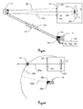
Mit dem Erfassen und Auswerten eines Bildes - mittels Bilderfassungs- und Bildverarbeitungseinheit - eines so genannten Messhilfsinstruments mit Markierungen, deren relative Lage zueinander bekannt ist, kann auf eine Orientierung eines an dem Messhilfsinstrument angeordneten Objekts (z.B. eine Sonde) im Raum geschlossen werden. Zusammen mit der bestimmten räumlichen Position des Zielpunkts kann ferner die Position und Orientierung des Objekts im Raum absolut und/oder relativ zum Lasertracker präzise bestimmt werden.By detecting and evaluating an image - by means of an image acquisition and image processing unit - of a so-called auxiliary measuring instrument with markings whose relative position to each other is known, an orientation of an object (for example a probe) arranged on the auxiliary measuring instrument can be inferred in space. Furthermore, together with the determined spatial position of the target point, the position and orientation of the object in space absolutely and / or relative to the laser tracker can be precisely determined.
Derartige Messhilfsinstrumente können durch so genannte Tastwerkzeuge, die mit ihrem Kontaktpunkt auf einem Punkt des Zielobjektes positioniert werden, verkörpert sein. Das Tastwerkzeug weist Markierungen, z.B. Lichtpunkte, und einen Reflektor auf, der einen Zielpunkt am Tastwerkzeug repräsentiert und mit dem Laserstrahl des Trackers anzielbar ist, wobei die Positionen der Markierungen und des Reflektors relativ zum Kontaktpunkt des Tastwerkzeuges präzise bekannt sind. Das Messhilfsinstrument kann in dem Fachmann bekannter Weise auch ein beispielsweise von Hand gehaltener, zur Distanzmessung ausgerüsteter Scanner für berührungslose Oberflächenvermessungen sein, wobei Richtung und Position des für die Distanzmessung verwendeten Scanner-Messstrahles relativ zu den Lichtpunkten und Reflektoren, die auf dem Scanner angeordnet sind, genau bekannt sind. Ein derartiger Scanner ist beispielsweise in der
Zur Entfernungsmessung weisen Lasertracker des Standes der Technik zumindest einen Distanzmesser auf, wobei dieser z.B. als Interferometer ausgebildet sein kann. Da solche Entfernungsmesseinheiten nur relative Distanzänderungen messen können, werden in heutigen Lasertrackern zusätzlich zu Interferometern so genannte Absolutdistanzmesser verbaut. Die in diesem Zusammenhang für die Distanzmessung eingesetzten Interferometer verwenden hauptsächlich - aufgrund der grossen Kohärenzlänge und der damit ermöglichten Messreichweite - als Lichtquellen HeNe-Gaslaser. Die Kohärenzlänge des HeNe-Lasers kann dabei einige hundert Meter betragen, so dass mit relativ einfachen Interferometer-Aufbauten die in der industriellen Messtechnik geforderten Reichweiten erzielt werden können. Eine Kombination eines Absolutdistanzmessers und eines Interferometers zur Entfernungsbestimmung mit einem HeNe-Laser ist beispielsweise aus der
Ausserdem wird in modernen Trackersystemen - zunehmend standardisiert - auf einem Feinanzielsensor eine Ablage des empfangenen Messstrahls von einer Nullposition ermittelt. Mittels dieser messbaren Ablage kann eine Positionsdifferenz zwischen dem Zentrum eines Retroreflektors und dem Auftreffpunkt des Laserstrahls auf dem Reflektor bestimmt und die Ausrichtung des Laserstrahls in Abhängigkeit dieser Abweichung derart korrigiert bzw. nachgeführt werden, dass die Ablage auf dem Feinanzielsensor verringert wird, insbesondere "Null" ist, und damit der Strahl in Richtung des Reflektorzentrums ausgerichtet ist. Durch das Nachführen der Laserstrahlausrichtung kann eine fortlaufende Zielverfolgung (Tracking) des Zielpunkts erfolgen und die Entfernung und Position des Zielpunkts fortlaufend relativ zum Messgerät bestimmt werden. Das Nachführen kann dabei mittels einer Ausrichtungsänderung des motorisiert bewegbaren, zur Ablenkung des Laserstrahls vorgesehenen Ablenkspiegels und/oder durch ein Schwenken der Anzieleinheit, die die strahlführende Laseroptik aufweist, realisiert werden.In addition, in modern tracker systems - increasingly standardized - a deposit of the received measuring beam from a zero position is determined on a precision target sensor. By means of this measurable tray, a position difference between the center of a retroreflector and the point of impact of the laser beam on the reflector can be determined and the orientation of the laser beam in dependence on this Deviation be corrected or tracked so that the filing is reduced on the Feinanzielsensor, in particular "zero", and that the beam is aligned in the direction of the reflector center. By tracking the laser beam alignment, continuous tracking of the target point can be performed and the distance and position of the target point continuously determined relative to the meter. The tracking can be realized by means of an alignment change of the motorized movable, provided for deflecting the laser beam deflection mirror and / or by pivoting the target unit, which has the beam-guiding laser optics.
Der beschriebenen Zielverfolgung muss ein Ankoppeln des Laserstrahls an den Reflektor vorausgehen. Hierzu kann am Tracker zusätzlich eine Erfassungseinheit zur Zielauffindung mit einem positionssensitiven Sensor und mit einem verhältnismässig grossen Sichtfeld angeordnet sein, wobei die durch den Sensor definierte optische Sensorachse und die Achse, entlang derer sich der Messlaserstrahl ausbreitet, versetzt zueinander sind. Zudem sind in gattungsgemässe Geräte zusätzliche Beleuchtungsmittel integriert, mit welchen das Ziel bzw. der Reflektor, insbesondere mit einer definierten, sich von der Wellenlänge der Distanzmessmittel unterscheidenden Wellenlänge, beleuchtet wird. Der Sensor kann in diesem Zusammenhang sensitiv auf einen Bereich um diese bestimmte Wellenlänge ausgebildet sein, um beispielsweise Fremdlichteinflüsse zu reduzieren oder komplett zu verhindern. Mittels der Beleuchtungsmittel kann das Ziel beleuchtet und mit der Kamera ein Bild des Ziels mit beleuchtetem Reflektor erfasst werden. Durch die Abbildung des spezifischen (wellenlängenspezifischen)The described target tracking must be preceded by a coupling of the laser beam to the reflector. For this purpose, a detection unit for target detection with a position-sensitive sensor and with a relatively large field of view may additionally be arranged on the tracker, the optical sensor axis defined by the sensor and the axis along which the measuring laser beam propagates being offset from one another. In addition, additional lighting means are integrated into devices of the generic type, with which the target or the reflector, in particular with a defined wavelength which differs from the wavelength of the distance measuring means, is illuminated. In this context, the sensor can be designed to be sensitive to a region around this specific wavelength in order, for example, to reduce or completely prevent extraneous light influences. By means of the illumination means, the target can be illuminated and the camera captured an image of the target with illuminated reflector. By mapping the specific (wavelength-specific)
Reflexes auf dem Sensor können die Reflexposition im Bild aufgelöst und damit ein Winkel relativ zur Erfassungsrichtung der Kamera und eine Richtung zum Ziel bzw. Reflektor bestimmt werden. Eine Ausführungsform eines Lasertrackers mit einer derartigen Zielsucheinheit ist beispielsweise aus der
In Abhängigkeit der so ableitbaren Richtungsinformation kann die Ausrichtung des Messlaserstrahls derart verändert werden, dass ein Abstand zwischen dem Laserstrahl und dem Reflektor, an welchen der Laserstrahl angekoppelt werden soll, verkleinert wird. Aufgrund des Versatzes der durch den Sensor definierten optischen Sensorachse und der Messachse der Messvorrichtung kann das Ausrichten des Strahls auf das Ziel mittels der sensorbasierten Richtungsbestimmung zum Ziel und damit das Ankoppeln nicht in einem direkten Schritt erfolgen. Für ein feststehendes Ziel sind hierfür mehrere Iterationsschritte mit jeweils einem Messvorgang (erneute Bestimmung einer Richtung zum Ziel mit dem Sensor) zur Annäherung des Laserstrahls erforderlich. An einer derartigen Annäherungsmethode ist daher nachteilig, dass das Aufsuchen und Anzielen des Ziels ein zeitintensiver Vorgang (da iterativ) ist und das Aufsuchen, insbesondere bei einer Relativbewegung des Ziels zum Sensor, nicht robust und eindeutig ist. Des Weiteren kann bei einer Bewegung des Ziels relativ zum Lasertracker keine Annäherung des Laserstrahls zum Ziel mehr gelingen, da sich eine Abweichung zwischen dem mittels des Sensors detektierten Ziel und dem Laserstrahl dabei fortlaufend verändert. Eine iterative Annäherung des Strahls an das Ziel kann aufgrund dieser während der Bewegung des Ziels anhaltenden Abweichungsveränderung so nicht erfolgen. Jeder Iterationsschritt mit einem erneuten Erfassen eines Reflexes entspricht dabei einer ersten solchen Messung auf ein (neues) Ziel. Generell ergibt sich somit ein grosser Nachteil solcher Systeme zur Zielauffindung darin, dass feststehende Ziele nur mit einem relativ grossen Zeitaufwand angezielt werden können und das direkte Anzielen bewegter Ziele unmöglich ist.Depending on the directional information derivable in this way, the orientation of the measuring laser beam can be changed in such a way that a distance between the laser beam and the reflector to which the laser beam is to be coupled is reduced. Due to the offset of the optical sensor axis defined by the sensor and the measuring axis of the measuring device, the beam can not be directed to the target by means of the sensor-based direction determination to the target and thus the coupling can not take place in a direct step. For a fixed target, this requires several iteration steps, each with one measurement process (redetermination of a direction to the target with the sensor) for approaching the laser beam. Therefore, it is disadvantageous in such an approximation method that searching for and targeting the target is a time-consuming process (because iterative), and the search, especially for a relative movement of the target to the sensor, is not robust and unambiguous. Furthermore, when the target is moved relative to the laser tracker, the laser beam can no longer approach the target since a deviation between the target detected by the sensor and the laser beam changes continuously. An iterative approach of the beam to the target can not be done as a result of this deviation change continuing during the movement of the target. Each iteration step with a new detection of a reflex corresponds to a first such measurement on a (new) target. In general, therefore, a major disadvantage of such target discovery systems is that fixed targets can only be targeted with a relatively large amount of time, and direct targeting of moving targets is impossible.
Es ist daher Aufgabe der vorliegenden Erfindung einen verbesserten Lasertracker mit einer Suchfunktionalität zum präzisen und schnelleren Auffinden und insbesondere Anzielen eines Ziels bereitzustellen.It is therefore an object of the present invention to provide an improved laser tracker with search functionality for accurate and faster retrieval and, in particular, targeting of a target.
Diese Aufgabe wird durch die Verwirklichung der kennzeichnenden Merkmale der unabhängigen Ansprüche gelöst. Merkmale, die die Erfindung in alternativer oder vorteilhafter Weise weiterbilden, sind den abhängigen Patentansprüchen zu entnehmen.This object is achieved by the realization of the characterizing features of the independent claims. Features which further develop the invention in an alternative or advantageous manner can be found in the dependent claims.
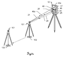
Die Erfindung betrifft einen Lasertracker zur fortlaufenden Verfolgung eines reflektierenden Ziels und zur Positionsbestimmung des Ziels. Der Tracker weist dabei einen Sockel, der eine Stehachse definiert, und eine Strahllenkeinheit zur Emission einer Messstrahlung und zum Empfang von zumindest einem Teil der am Ziel reflektierten Messstrahlung auf, wobei die Strahllenkeinheit um die Stehachse und eine Neigungsachse relativ zur Basis motorisiert schwenkbar ist und durch eine Emissionsrichtung der Messstrahlung eine Messachse definiert ist. Ferner verfügt der Lasertracker über einen positionssensitiven Feinanzieldetektor, der ein Feinanzielsichtfeld definiert, zur Feinanzielung und Verfolgung des Ziels mittels Detektieren von Messstrahlung, welche vom Ziel reflektiert ist, und eine Feindistanzmesseinheit zur präzisen Distanzbestimmung zum Ziel vermittels der Messstrahlung und über eine Winkelmessfunktionalität zur Bestimmung einer Ausrichtung der Strahllenkeinheit relativ zum Sockel. Weiter weist der Lasertracker eine Zielsucheinheit auf, welche Beleuchtungsmittel zur Beleuchtung des Ziels mit elektromagnetischer Beleuchtungsstrahlung und eine ein Sichtfeld definierende Kamera aufweist, wobei die optische Achse der Kamera bekannt versetzt zur Messachse angeordnet ist. Die Kamera verfügt über einen positionssensitiven Detektor, wodurch in einem Bild vom reflektierenden Ziel zurückgeworfene Beleuchtungsstrahlung als ein oder mehrere Lichtflecke erfassbar ist und eine Position im Bild für die erfasste Beleuchtungsstrahlung bestimmbar ist. Diese Bildposition der vom Ziel zurückgeworfenen Beleuchtungsstrahlung auf dem Detektor ist abhängig von der Position des Ziels relativ zum Lasertracker, weshalb aus ihr eine Zielpositionsinformation ableitbar ist. Weiter weist der erfindungsgemässe Lasertracker eine derart konfigurierte Steuerungs- und Auswerteeinheit auf, dass bei Ausführung einer Suchfunktionalität ein Auffinden des Ziels in Abhängigkeit der Bildposition bzw. der daraus abgeleiteten Zielpositionsinformation erfolgt.The invention relates to a laser tracker for continuously tracking a reflective target and for determining the position of the target. The tracker in this case has a base, which defines a standing axis, and a beam steering unit for emitting a measuring radiation and for receiving at least a portion of the measuring radiation reflected at the target, wherein the beam steering unit is pivotable about the vertical axis and a tilt axis relative to the motorized base and through an emission direction of the measuring radiation is defined a measuring axis. Further, the laser tracker has a position sensitive fine range detector defining a fine field of view for fine tracking and tracking of the target by detecting measurement radiation reflected from the target and an enemy distance measuring unit for precise distance determination to the target through the measuring radiation and via angular measurement functionality for determining an orientation of the beam steering unit relative to the base. Furthermore, the laser tracker has a target search unit, which has illumination means for illuminating the target with electromagnetic illumination radiation and a camera defining a field of view, wherein the optical axis of the camera is arranged offset to the measurement axis. The camera has a position-sensitive detector, as a result of which illumination radiation reflected in an image by the reflecting target can be detected as one or more light spots and a position in the image can be determined for the detected illumination radiation. This image position of the illumination radiation reflected by the target on the detector is dependent on the position of the target relative to the laser tracker, from which a target position information can be derived. Furthermore, the laser tracker according to the invention has a control and evaluation unit configured in such a way that, when a search functionality is carried out, the target is found as a function of the image position or the target position information derived therefrom.
Insbesondere wird erfindungsgemäss mittels der Steuerungs- und Auswerteeinheit durch das Auffinden des Ziels eine Abweichung der Ausrichtung der Messachse von der Richtung zum Ziel bestimmt, welche sich vorzugsweise in unterschiedlichen Richtungswinkeln ausdrückt, so dass als Abweichung bspw. jeweils eine Differenz der horizontalen und der vertikalen Richtungswinkel bestimmt wird. Unter der Richtung zum Ziel ist hierbei diejenige Ausrichtung der Strahllenkeinheit zu verstehen, die sie einnehmen muss, damit Messstrahlung auf das Ziel trifft. Im Unterschied dazu wird unter einer Zielrichtung eine Zielpositionsinformation verstanden, welche eine Richtungsangabe beinhaltet, die insbesondere an ein Element der Zielsucheinheit anknüpft und aufgrund des Versatzes der Messachse zur Kamera oder zu anderen Elementen der Zielsucheinheit nicht mit der Richtung zum Ziel gleichzusetzen ist.In particular, according to the invention by means of the control and evaluation unit by finding the target, a deviation of the orientation of the measuring axis from the direction to the destination is determined, which preferably expresses in different direction angles, so that as a deviation, for example, in each case a difference of the horizontal and the vertical direction angle is determined. In this case, the direction to the target is to be understood as that orientation of the beam steering unit which it has to assume in order for measuring radiation to strike the target. In contrast, under a destination direction, destination information becomes understood, which includes a direction indication, in particular linked to an element of the target search unit and is not to be equated with the direction to the target due to the offset of the measuring axis to the camera or to other elements of the target search unit.
Durch das Ergebnis der Suche, d.h. das Auffinden des Ziels, ist prinzipiell die Position des Ziels relativ zum Lasertracker bekannt. Diese kann als Grobposition bezeichnet werden, da sie weniger exakt ist als die Position, die auf Grundlage einer Messung vermittels der Messstrahlung ermittelbar ist. Entsprechend ist eine durch die Zielsucheinheit bestimmte Entfernung zum Ziel als Grobentfernung bezeichnet. Die ermittelten groben Lokalisationsdaten sind ausreichend, um eine Ausrichtung des Messstrahls auf das Ziel herbeiführen zu können. Basierend auf dem Auffinden des Ziels wird mittels der Steuerungs- und Auswerteeinheit, unter Berücksichtigung der bekannten relativen Anordnung der Zielsucheinheit oder einzelner Komponenten der Zielsucheinheit und der Strahllenkeinheit zueinander, die Strahllenkeinheit und damit der Messstrahl auf das Ziel ausgerichtet. Insbesondere werden die Differenzen der Richtungswinkel von tatsächlicher und gewünschter Messachsenrichtung ermittelt und die Ausrichtung solange verändert, bis, zumindest weitgehend, die Differenzen gleich Null sind und/oder der Messstrahl vom Ziel reflektiert und vom Feinanzieldetektor registriert wird.By the result of the search, i. locating the target, in principle, the position of the target relative to the laser tracker is known. This can be referred to as coarse position because it is less accurate than the position that can be determined on the basis of a measurement by means of the measuring radiation. Accordingly, a distance to the destination determined by the homing unit is referred to as a rough distance. The coarse localization data determined are sufficient to bring about an alignment of the measuring beam with the target. Based on the finding of the target, the beam steering unit and thus the measuring beam are aligned with the target by means of the control and evaluation unit, taking into account the known relative arrangement of the target search unit or individual components of the target search unit and the beam steering unit. In particular, the differences in the directional angles of the actual and desired measuring axis directions are determined and the orientation is changed until, at least largely, the differences are equal to zero and / or the measuring beam is reflected by the target and registered by the fine-range detector.
Das Ausrichten der Messstrahlung erfolgt in zwei Achsen (Stehachse bzw. vertikale Achse und Neigungsachse bzw. Kippachse) mittels an dem Lasertracker zum Schwenken der Strahllenkeinheit vorgesehenen Motoren, insbesondere Stellmotoren, wobei diese vermittels der Steuerungs- und Abzieleinheit ansteuerbar sein können.The alignment of the measuring radiation takes place in two axes (standing axis or vertical axis and inclination axis or tilting axis) by means provided on the laser tracker for pivoting the beam steering unit motors, in particular servo motors, which can be controlled by means of the control and target unit.
Erfindungsgemässe kann der Lasertracker eine um die Stehachse relativ zum Sockel motorisiert schwenkbare und die Neigungsachse bzw. eine horizontale oder liegende Achse definierende Stütze und eine als Strahllenkeinheit ausgebildete, um die Neigungsachse relativ zur Stütze motorisiert schwenkbare Anzieleinheit mit einer Teleskopeinheit zur Emission der Messstrahlung und zum Empfang von zumindest einem Teil der am Ziel reflektierten Messstrahlung aufweisen.According to the invention, the laser tracker can pivot about the standing axis relative to the base pivoting and the axis of inclination or a horizontal or horizontal axis defining support and trained as a beam steering unit, the tilt axis relative to the support motorized pivoting target unit with a telescope unit for emission of the measuring radiation and for receiving of at least part of the measuring radiation reflected at the target.
Durch das Auffinden des Ziels mittels der Suchfunktionalität kann die Messstrahlung direkt auf das Ziel ausgerichtet, von diesem reflektiert und die Entfernung zum Ziel exakt bestimmt werden. Zur Entfernungsmessung können hierfür sowohl eine Absolutdistanzmesseinheit und ein Interferometer im Lasertracker angeordnet sein, wobei für beide Messeinheiten jeweils eine Strahlquelle vorgesehen sein kann und die emittierten Strahlungen sich entlang eines gemeinsamen Messpfads und schliesslich auf einer gemeinsamen Messachse ausbreiten können.By finding the target by means of the search functionality, the measuring radiation can be aimed directly at the target, reflected by it and the distance to the target can be determined exactly. To measure the distance, both an absolute distance measuring unit and an interferometer can be arranged in the laser tracker, wherein a beam source can be provided for both measuring units and the emitted radiation can propagate along a common measuring path and finally on a common measuring axis.
Erfindungsgemäss können die Kamera und die Messachse derart zueinander angeordnet sein, dass die Messachse zumindest teilweise im Sichtfeld der Kamera liegt. Insbesondere bei der Anzielung bewegter Ziele ist eine solche Überscheidung der Messachse mit dem Sichtbereich im Rahmen des Anzielprozesses vorteilhaft. Erfindungsgemäss kann die Kamera dabei derart angeordnet sein, dass deren optische Achse parallel versetzt oder in einem definierten Winkel relativ zur Messachse angeordnet ist. Generell ist die im Zusammenhang mit der vorliegenden Erfindung genannte Kamera mit einem positionssensitiven Detektor derart ausgebildet, dass das Sichtfelder relativ zur Messstrahlung bzw. zum Öffnungswinkel der Messstrahlung gross ist, d.h. das Sichtfeld ist grösser als der Öffnungswinkel des Strahls, um einen verhältnismässig grossen Bereich einer Messumgebung mit potentiellen Zielen zu erfassen.According to the invention, the camera and the measuring axis can be arranged relative to one another such that the measuring axis lies at least partially in the field of view of the camera. In particular, when aiming at moving targets, such a distinction between the measuring axis and the field of view is advantageous in the context of the targeting process. According to the invention, the camera can be arranged such that its optical axis is offset in parallel or at a defined angle relative to the measuring axis. In general, the camera mentioned in connection with the present invention is designed with a position-sensitive detector such that the field of view is large relative to the measurement radiation or to the opening angle of the measurement radiation, ie Field of view is greater than the aperture angle of the beam to detect a relatively large area of a measurement environment with potential targets.
Im Gegensatz zu der Kamera weist ein anderer Typ von positionssensitivem Detektor (PSD), welcher beispielsweise in der Teleskopeinheit eines Lasertrackers verbaut ist und zur Feinanzielung und Verfolgung eines Ziels dient, einen engen Sichtbereich auf, bspw. von 0,67° oder weniger, oder für einen PSD mit parallelem Sichtfeld (field of view) bspw. von ±4mm oder weniger. Diese PSD ist derart angeordnet, dass sie die am Ziel reflektierte Messstrahlung detektieren kann und auf Basis dieser Detektion eine Ablage der erfassten Strahlung von einem Sollwert ermittelbar macht (die PSD ist also an den Messstrahlengang gekoppelt). In Abhängigkeit dieser Ablage kann dann eine Abweichung des Messlaserstrahls vom Zentrum eines Retroreflektors bestimmt werden und diese Strahlung so neu ausgerichtet werden, dass der Strahl zentral auf den Reflektor trifft. Insbesondere wird allein der retroreflektierte Laserstrahl detektiert und dessen Position ausgewertet.In contrast to the camera, another type of position sensitive detector (PSD), for example, mounted in the telescope unit of a laser tracker and used for fine targeting and tracking a target, has a narrow field of view, for example 0.67 ° or less, or for a PSD with a field of view, for example, of ± 4 mm or less. This PSD is arranged such that it can detect the measurement radiation reflected at the target and, on the basis of this detection, makes a storage of the detected radiation detectable from a nominal value (the PSD is thus coupled to the measurement beam path). Depending on this deposit, a deviation of the measuring laser beam from the center of a retroreflector can then be determined and this radiation can be realigned such that the beam hits the reflector centrally. In particular, only the retroreflected laser beam is detected and its position evaluated.
Die Beleuchtungsmittel der Zielsucheinheit können erfindungsgemäss insbesondere Beleuchtungsstrahlung aussenden, die sich von der Messstrahlung unterscheidet, insbesondere hinsichtlich Wellenlänge und Fokussierung. Vorzugsweise emittieren die Beleuchtungsmittel Licht im InfrarotBereich, insbesondere innerhalb eines engen IR-Wellenlängenbereichs. Das Licht kann dabei divergent ausgesandt werden, damit ein grosser Umgebungsbereich des Lasertrackers beleuchtbar ist. Insbesondere sind die Beleuchtungsmittel ausgeprägt als lichtemittierende Dioden (LEDs), wobei die Lichtintensität dynamisch variierbar sein kann, wodurch eine Anpassung der Beleuchtung an unterschiedliche Bedingungen, bspw. verschiedene Zielgrössen oder Zielentfernungen, durchführbar ist. Entsprechend ist die Kamera vorzugsweise derart ausgebildet, dass speziell oder ausschliesslich Licht der Wellenlänge der verwendeten Beleuchtungsstrahlung erfasst wird. Dazu kann die Kamera bzw. der positionssensitive Detektor, zumindest im Wesentlichen, sensitiv nur für Licht der entsprechenden Wellenlänge oder ein Filter vorhanden sein. Ein solcher Filter kann bspw. ein Aussortieren von Lichtfrequenzen vor dem Erfassen durch den Detektor ermöglichen, in dem nur Licht bestimmter Wellenlängen durchgelassen wird, oder als Algorithmus ausgeprägt sein, mit dem nach dem Erfassen ein spektrales Filtern stattfindet.According to the invention, the illumination means of the target search unit can emit in particular illumination radiation which differs from the measurement radiation, in particular with regard to wavelength and focusing. The illumination means preferably emit light in the infrared range, in particular within a narrow IR wavelength range. The light can be emitted divergently so that a large surrounding area of the laser tracker can be illuminated. In particular, the illumination means are pronounced as light emitting diodes (LEDs), wherein the light intensity can be varied dynamically, whereby an adaptation of the illumination to different Conditions, for example, different target sizes or target distances, is feasible. Accordingly, the camera is preferably designed such that especially or exclusively light of the wavelength of the illumination radiation used is detected. For this purpose, the camera or the position-sensitive detector, at least substantially, be sensitive only to light of the corresponding wavelength or a filter. Such a filter may, for example, allow sorting out of light frequencies prior to detection by the detector, in which only light of certain wavelengths is transmitted, or be pronounced as an algorithm with which spectral filtering takes place after the detection.
Gemäss einer weiteren Ausführung der Erfindung wird eine Bildposition in einem erfassten Bild mittels Bildverarbeiten derart bestimmt, dass durch die jeweilige Bildposition eine Lage im Bild einer im jeweiligen Bild erfassten Strahlungsquerschnittsform erscheint, repräsentiert wird. Insbesondere erfolgt das Bestimmen einer Bildposition mittels Schwerpunktberechnen basierend auf der im jeweiligen Bild erfassten Strahlungsquerschnittsform, insbesondere mittels Helligkeits- und/oder Kontrastanalyse, und/oder mittels Matchen, insbesondere In-Übereinstimmung-Bringen, der im jeweiligen Bild erfassten Strahlungsquerschnittsform mit einem gespeicherten Muster anhand einer Best-Fit-Methode - dies insbesondere mit Subbildpunktgenauigkeit, wobei anhand der in Übereinstimmung gebrachten Lage des Musters im Bild die jeweilige Zielposition der im Bild erfassten Strahlung bestimmt wird, insbesondere mit Subbildpunktgenauigkeit. Insbesondere ist hierbei für das gespeicherte Muster eine Information mitgespeichert, die eine musterintern definierte, für die letztendliche Ermittlung der Zielposition heranzuziehende Musterposition innerhalb des Musters ableiten lässt, im Speziellen wobei die Information die musterintern definierte Musterposition selbst ist oder ein definierter Muster-Positions-Bestimmungsalgorithmus wie etwa ein Musterschwerpunkt-Bestimmungsalgorithmus.According to a further embodiment of the invention, an image position in a captured image is determined by means of image processing in such a way that a position in the image of a radiation cross-sectional shape detected in the respective image appears through the respective image position. In particular, the determination of an image position by means of center of gravity calculation is based on the radiation cross-sectional shape detected in the respective image, in particular by means of brightness and / or contrast analysis, and / or by means of matching, in particular matching, of the radiation cross-sectional shape detected in the respective image with a stored pattern a best-fit method - in particular with subpixel accuracy, wherein the respective target position of the radiation detected in the image is determined on the basis of the matched position of the pattern in the image, in particular with subpixel accuracy. In particular, in this case, an information is stored for the stored pattern, which defines a pattern-internal, for the eventual Determining the target position within the pattern, in particular where the information is the pattern-internally defined pattern position itself or a defined pattern position determination algorithm such as a pattern centroid determining algorithm.
Gemäss einer bestimmten erfindungsgemässen Ausführungsform weist der Lasertracker eine Kalibrierfunktion auf, bei deren Ausführung eine bekannte Positionierung und Ausrichtung der Kamera bzw. deren optischer Achse relativ zur Messachse und eine bekannte Positionierung und/oder Ausrichtung der Zielsucheinheit oder von Komponenten der Zielsucheinheit relativ zur Kamera und/oder Messachse bestimmt werden. Dabei wird insbesondere das Ziel in verschiedenen Positionen bereitgestellt und mittels der Messstrahlung angezielt und vermessen, für jede Position des Ziels wenigstens eine Zielpositionsinformation mittels der Zielsucheinheit bestimmt und aus dem Vermessen des Ziels und der dazu bestimmten Zielpositionsinformation eine relative Positionierung und Ausrichtung abgeleitet.According to a specific embodiment of the invention, the laser tracker has a calibration function, in the execution of which a known positioning and alignment of the camera or its optical axis relative to the measurement axis and a known positioning and / or orientation of the target search unit or of components of the target search unit relative to the camera and / or measuring axis are determined. In particular, the target is provided in different positions and targeted and measured by the measuring radiation, determined for each position of the target at least one target position information by means of the target search unit and derived from the measurement of the target and the target position information determined therefor relative positioning and orientation.
Ferner betrifft die Erfindung ein Verfahren zum Suchen und Auffinden eines Ziels mit einem Lasertracker, wobei der Lasertracker einen eine Stehachse definierende Sockel und eine Strahllenkeinheit zum Emittieren einer Messstrahlung und zum Empfangen von zumindest einem Teil der am Ziel reflektierten Messstrahlung mittels eines Feinanzieldetektors aufweist, wobei die Strahllenkeinheit um die Stehachse und eine Neigungsachse relativ zum Sockel motorisiert schwenkbar ist und durch eine Emissionsrichtung der Messstrahlung eine Messachse definiert ist. Weiters erfolgt ein Beleuchten des Ziels mit elektromagnetischer Beleuchtungsstrahlung und ein positionssensitives Erfassen von am Ziel reflektierter Beleuchtungsstrahlung, woraus eine Zielpositionsinformation ableitbar ist, mit einer am Lasertracker angeordneten und ein Sichtfeld definierenden Kamera mit einem positionssensitiven Detektor, wobei die Kamera mit deren optischer Achse versetzt zur Messachse angeordnet ist. Das Auffinden des Ziels erfolgt in Abhängigkeit der Beleuchtungsstrahlungsposition oder einer daraus abgeleiteten Zielpositionsinformation.The invention further relates to a method for searching for and finding a target with a laser tracker, wherein the laser tracker has a stand axis defining a standing axis and a beam steering unit for emitting a measuring radiation and for receiving at least a part of the measuring radiation reflected by the target by means of a fine field detector; Beam steering unit about the standing axis and an inclination axis is motorized pivotable relative to the base and a measuring axis is defined by an emission direction of the measuring radiation. Furthermore, a lighting of the target with electromagnetic illumination radiation and a position-sensitive detection takes place of reflected at the target illumination radiation, from which a target position information is derived, arranged with a laser tracker and a field of view defining camera with a position-sensitive detector, wherein the camera is arranged with its optical axis offset from the measuring axis. The finding of the target takes place as a function of the illumination radiation position or of a target position information derived therefrom.
Im Rahmen des Verfahrens erfolgt durch das Auffinden des Ziels insbesondere das Bestimmen einer, insbesondere richtungswinkelbezogener, Abweichung der Messachsenausrichtung von einer Richtung zum Ziel. Erfindungsgemäss kann basierend auf der Zielauffindung, insbesondere basierend auf einer anhand des Suchergebnisses bestimmten Grobposition des Ziels, ein automatisches Ausrichten der Strahllenkeinheit auf das Ziel erfolgen, so dass Messstrahlung dergestalt auf das Ziel trifft, dass reflektierte Anteile davon vom Feinanzieldetektor erfasst und detektiert werden können. Bspw. kann eine Differenz der jeweiligen azimutalen und vertikalen Richtungswinkel berechnet werden. Ein Ausrichten der Messstrahlung auf das Ziel erfolgt damit, indem der Ausrichtung der Strahllenkeinheit solange geändert wird, bis der Wert der Differenz zumindest weitgehend gleich Null ist.In the context of the method, by finding the target, in particular, the determination of a deviation of the measuring axis orientation from one direction to the target takes place, in particular direction angle-related. According to the invention, based on the target finding, in particular based on the coarse position of the target determined by the search result, an automatic alignment of the beam steering unit to the target can take place so that measuring radiation hits the target in such a way that reflected portions thereof can be detected and detected by the fine range detector. For example. a difference of the respective azimuthal and vertical direction angles can be calculated. Aligning the measuring radiation to the target is done by the orientation of the beam steering unit is changed until the value of the difference is at least substantially equal to zero.
Die Erfindung betrifft des Weiteren ein Computerprogrammprodukt mit Programmcode, der auf einem maschinenlesbaren Träger gespeichert ist, zur Steuerung bzw. Durchführung des erfindungsgemässen Verfahrens.The invention further relates to a computer program product with program code, which is stored on a machine-readable carrier, for controlling or carrying out the method according to the invention.
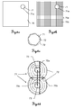
Hinsichtlich eines ersten Aspekts der Erfindung verfügt die Zielsucheinheit des Lasertrackers über wenigstens ein Paar aus einem ersten und einem zweiten Beleuchtungsmittel, die einen fixen Abstand zueinander haben, welcher eine erste Basislänge definiert und bekannt sein kann. Dabei sind die Beleuchtungsmittel insbesondere symmetrisch um die optische Achse der Kamera angeordnet. Durch ein Beleuchten des Ziels mit Beleuchtungsstrahlung des Paars ist vom Ziel reflektierte Beleuchtungsstrahlung als ein erster und ein zweiter Lichtfleck durch die Kamera erfassbar. Bei Ausführung der Suchfunktionalität werden erfindungsgemäss in Abhängigkeit des ersten und/oder zweiten Lichtflecks mindestens eine Bildposition bestimmt, woraus eine Zielpositionsinformation ermittelbar ist. Eine Bildposition kann dabei z.B. die Position eines der beiden Lichtflecke im Bild sein oder eine aus den Positionen beider Lichtflecke ermittelte, gemeinschaftliche Position sein. Des weiteren wird eine Parallaxenkorrigierinformation mittels Bildverarbeiten bestimmt, in welcher eine Separation der Lichtflecke berücksichtigt wird und die abhängig ist von einer Distanz der beiden Lichtflecke zueinander. Die Parallaxenkorrigierinformation kann insbesondere der Wert der Distanz selbst sein. Das Auffinden des Ziels erfolgt dann unter Heranziehung der mindestens einen Bildposition in Abhängigkeit der Parallaxenkorrigierinformation.In a first aspect of the invention, the laser tracker's target search unit has at least one pair of first and second illumination means have a fixed distance to each other, which defines a first base length and may be known. In this case, the illumination means are arranged in particular symmetrically about the optical axis of the camera. By illuminating the target with illumination radiation of the pair, illumination radiation reflected by the target can be detected as a first and a second light spot by the camera. Upon execution of the search functionality, at least one image position is determined according to the invention as a function of the first and / or second light spot, from which a target position information can be determined. An image position may be, for example, the position of one of the two light spots in the image or a common position determined from the positions of both light spots. Furthermore, a parallax correction information is determined by means of image processing in which a separation of the light spots is taken into account and which is dependent on a distance of the two light spots from each other. The parallax correction information may in particular be the value of the distance itself. The finding of the target then takes place using the at least one image position as a function of the parallax correction information.
Die erfindungsgemässe Zielsucheinheit bietet den Vorteil, dass mit der Bestimmung der Parallaxenkorrigierinformation eine zusätzliche Verwendung der Lichtflecke in ihrer separaten Erscheinung erfolgt, wodurch im Gegensatz zu lediglich einer Bestimmung einer einzigen Zielpositionsinformation aus lediglich einer gemeinschaftlichen Bildposition durch eine Zusammenschau aus beiden Lichtflecken, bspw. durch Verwendung eines Lichtfleckpositionsmittelwerts, nicht nur eine Information über die Richtung zum Ziel relativ zur Zielsucheinheit ermittelbar ist; da die Distanz der durch die beiden Beleuchtungsmittel erzeugten Lichtflecke auf dem Detektor bei fixem Abstand der Beleuchtungsmittel von der Entfernung des Ziels zum Lasertracker abhängig ist, ist mit erfindungsgemässem Lasertracker auch eine Information über die Entfernung zum Ziel als weitere Zielpositionsinformation bestimmbar. Damit ist ein eindeutiges Auffinden des Ziels durchführbar. Somit ist trotz der Parallaxe, also des Versatzes zwischen der optischen Kameraachse der Zielsucheinheit und der Messachse, der Messstrahl auf das Ziel in einem direkten Schritt ausrichtbar, ohne auf ein iteratives Vorgehen angewiesen zu sein. Zudem ermöglicht das erfindungsgemässe eindeutige Auffinden des Ziels mittels eines Erfassungsvorgangs auch eine Ausrichtung des Messstrahls auf ein bewegtes Ziel.The inventive target search unit has the advantage that with the determination of Parallaxenkorrigierinformation additional use of the light spots in their separate appearance, whereby in contrast to only one determination of a single target position information from only a common image position by a synopsis of two light spots, eg. By use a light spot position average, not only information about the direction to the destination relative to the target search unit is determined; because the distance the light spots generated by the two illumination means on the detector at a fixed distance of the illumination means from the distance of the target to the laser tracker is determined with the laser tracker according to the invention also information about the distance to the target as further target position information. This makes it possible to uniquely locate the target. Thus, despite the parallax, that is, the offset between the optical camera axis of the target search unit and the measuring axis, the measuring beam can be aligned to the target in a direct step, without having to rely on an iterative approach. In addition, the unique finding of the target according to the invention by means of a detection process also makes it possible to align the measuring beam with a moving target.
Im Gegensatz zu Methoden der Zielsuche des Standes der Technik kann die Steuerungs- und Auswerteeinheit dabei erfindungsgemäss derart konfiguriert sein, dass bei Ausführung der Suchfunktionalität Vieldeutigkeiten, die bei einer Heranziehung von nur einer mittels einer Bildposition bestimmten Zielpositionsinformation zum Auffinden des Ziels und durch eine durch die Messrichtung und der optischen Achse der Kamera gegebene Parallaxe vorhanden sind, durch eine Heranziehung mindestens einer Position im Bild von erfasster Beleuchtungsstrahlung als auch der Parallaxenkorrigierinformation zum Auffinden des Ziels aufgelöst werden.In contrast to methods of target search in the prior art, the control and evaluation unit according to the invention can be configured such that, when performing the search functionality, ambiguities resulting from using only one destination position information determined by image position to find the destination and one through the Measuring direction and the optical axis of the camera given parallax are present, be resolved by an attraction of at least one position in the image of detected illumination radiation and the Parallaxenkorrigierinformation to find the target.
Um mittels der Zielsucheinheit das Ziel aufzufinden, wird die fixe Basislänge, welche explizit oder implizit, z.B. in von ihr abhängigen Kenngrössen oder Wertetabellen, gegeben ist, insbesondere wie folgend beschrieben genutzt. Diese ist erfindungsgemäss durch den Abstand des Beleuchtungsmittelpaars zueinander festgelegt. Durch diese Kenntnis kann aus einer Information, welche aus der Distanz der Lichtflecke auf dem Detektor, die durch Reflexion der Strahlung des Beleuchtungsmittelpaars am Ziel entstanden sind, ermittelt ist, auf eine Entfernung des Ziels geschlossen werden, da die Distanz der beiden Lichtflecke bei fixer Basislänge entfernungsabhängig ist. Zusammen mit einer Zielrichtung, die sich aus einer aus der reflektierten Beleuchtungsstrahlung bestimmten Bildposition ergibt, ist, bspw. durch allgemein bekannte Triangulationsprinzipien, das Ziel lokalisierbar, mit einer ausreichenden Präzision, um eine Feinanzielung zu ermöglichen. In diesem Sinn ist durch die erfindungsgemässe Zielsucheinheit eine eindeutige Grobposition des Ziels ermittelbar. Erfindungsgemäss kann die Steuerungs- und Auswerteeinheit alternativ derart konfiguriert sein, dass eine Grobposition in Abhängigkeit einer ersten und einer zweiten Zielrichtung bestimmt wird. Alternativ kann eine Grobposition erfindungsgemäss durch Nachschlagen in einer Look-Up-Tabelle bestimmt werden, in der bei Ausführung der Suchfunktionalität eine Grobposition anhand von Bildpositionen und Parallaxenkorrigierinformationen direkt abgelesen wird. Eine solche Zuordnung mit Referenzwerten kann bspw. in der Steuerungs- und Auswerteeinheit hinterlegt sein.In order to find the destination by means of the destination search unit, the fixed basic length, which is given explicitly or implicitly, for example in parameters or value tables dependent thereon, is used in particular as described below. This is according to the invention defined by the distance of the pair of lighting means to each other. Through this knowledge can from an information, which is determined from the distance of the light spots on the detector, which are caused by reflection of the radiation of the lighting agent pair at the target, are concluded to a distance of the target, since the distance of the two light spots at a fixed base length is distance-dependent. Together with an aiming direction resulting from an image position determined from the reflected illuminating radiation, the target can be localized, for example by well-known principles of triangulation, with sufficient precision to enable fine-graining. In this sense, a unique coarse position of the destination can be determined by the target search unit according to the invention. According to the invention, the control and evaluation unit may alternatively be configured such that a coarse position is determined as a function of a first and a second target direction. Alternatively, according to the invention, a coarse position can be determined by looking up in a look-up table, in which a coarse position is directly read on the basis of image positions and parallax correction information when the search functionality is executed. Such an assignment with reference values can, for example, be stored in the control and evaluation unit.
Bei einer zusammenschauenden Heranziehung des ersten und zweiten Lichtflecks zur Ermittlung nur einer Zielpositionsinformation daraus und einem Versatz der optischen Achse der Kamera relativ zur Messachse der Messstrahlung kann das Ziel mittels der Kamera nicht eindeutig lokalisiert werden, da aus einem Bild so nur eine Richtungsinformation ableitbar ist, jedoch keine Entfernung zum Ziel bestimmbar und somit keine Lokalisierung des Ziels möglich ist. Ein Ausrichten des Messstrahls auf das Ziel ist somit nicht in einem Schritt möglich. Ein Vorteil der erfindungsgemässen Heranziehung der beiden durch die zwei in einem bekannten Verhältnis positionierten Beleuchtungsmittel erzeugten Lichtflecke ist daher, dass das Ziel direkt gefunden werden kann und kein iteratives Annähern an das Ziel durchgeführt werden muss, sondern das Anzielen direkt erfolgen kann.In the case of a combined use of the first and second light spots for determining only a target position information therefrom and an offset of the optical axis of the camera relative to the measurement axis of the measurement radiation, the target can not be unambiguously located by means of the camera, since only one direction information can be derived from an image, However, no distance to the destination determined and thus no localization of the target is possible. Aligning the measuring beam to the target is thus not in one step possible. An advantage of the use according to the invention of the two light spots produced by the two illumination means positioned in a known ratio is therefore that the target can be found directly and no iterative approach to the target has to be carried out, but the targeting can take place directly.
Ein weiterer Vorteil der vorliegenden Erfindung besteht darin, dass ein derartiges direktes Anzielen mit nur einer Kamera erreicht wird, ohne also weitere Mittel, bspw. eine zweite Kamera, in die Zielsucheinheit aufnehmen zu müssen. Zielsucheinheiten nach dem Stand der Technik weisen bereits erforderliche Mittel auf, insbesondere eine Kamera mit einem positionssensitiven Detektor und wenigstens zwei Beleuchtungsmitteln.A further advantage of the present invention is that such a direct aiming is achieved with only one camera, without having to take up further means, for example a second camera, in the target search unit. Target search units according to the prior art have already required means, in particular a camera with a position-sensitive detector and at least two illumination means.
Zur Erhöhung der Genauigkeit der Zielauffindung und/oder zur Anpassung an die Grösse des Ziels kann die Zielsucheinheit über wenigstens ein weiteres Paar von Beleuchtungsmitteln verfügen mit einem Abstand zueinander, der von dem des ersten Beleuchtungsmittelpaars differiert, wodurch eine zweite, insbesondere eine grössere, Basislänge definiert ist. Eine grössere Basislänge kann vor allem zur Erhöhung der Genauigkeit der Bestimmung einer Grobposition bzw. Grobentfernung dienen, wenn das Ziel sich relativ weit entfernt vom Lasertracker befindet, da sich das Verhältnis von Basislänge zur Zielentfernung auf den Messfehler auswirkt. Eine grössere Basislänge ist hierfür günstiger. Die Basislänge ist bei Verwendung retroreflektierender Ziele jedoch dadurch begrenzt, dass der Abstand zwischen Beleuchtungsmittel und Kamera nur so gross sein darf, dass retroreflektierte Beleuchtungsstrahlung noch von der Kamera erfassbar ist. Der maximal mögliche Abstand hängt dabei u.a. von der Grösse des kleinsten Reflektorziels ab, das auffindbar sein soll. Um eine möglichst grosse Basislänge und damit Genauigkeit unter Berücksichtigung des maximal möglichen Abstands zu erreichen, kann erfindungsgemäss eine Auswahl des zur Zielauffindung zu benutzenden Beleuchtungsmittelpaars in Abhängigkeit der Zielbeschaffenheit und/oder geschätzten Zieldistanz erfolgen. Dies kann insbesondere durch die Steuerungs- und Auswerteeinheit automatisiert erfolgen. Erfindungsgemäss kann auch ein Beleuchten des Ziels durch mehrere Beleuchtungsmittelpaare und entsprechend ein Erfassen mehrerer Lichtfleckpaare erfolgen und durch eine unabhängige Bestimmung von z.B. vier Lichtfleckpositionen und damit einhergehend zwei Lichtfleckdistanzen die Genauigkeit einer Bestimmung einer Richtung zum Ziel erhöht werden. Insbesondere kann ein Ausführen der Suchfunktionalität zuerst mit der ersten Basislänge durchgeführt werden, und falls dadurch kein eindeutiges Auffinden des Ziels erreichbar ist, ein Umschalten auf eine Verwendung der zweiten Basislänge erfolgen.To increase the accuracy of the target finding and / or to adapt to the size of the target, the target search unit may have at least one further pair of illumination means spaced apart from that of the first pair of illumination means, thereby defining a second, in particular a larger, base length is. A larger base length can be used primarily to increase the accuracy of the determination of a coarse position or coarse removal, if the target is relatively far away from the laser tracker, since the ratio of base length to the target distance affects the measurement error. A larger base length is cheaper. The base length is limited when using retroreflective goals, however, in that the distance between the illumination means and the camera may only be so great that retroreflected illumination radiation can still be detected by the camera. The maximum possible distance depends, inter alia, on the size of the smallest reflector target that can be found should. In order to achieve the largest possible base length and thus accuracy taking into account the maximum possible distance, according to the invention, a selection of the pair of illumination means to be used for the target finding can be made as a function of the target condition and / or estimated target distance. This can be done automatically in particular by the control and evaluation. According to the invention, it is also possible to illuminate the target through a plurality of pairs of illumination means and correspondingly detect multiple pairs of light spots and to increase the accuracy of a determination of a direction to the target by independent determination of eg four light spot positions and, consequently, two light spot distances. In particular, execution of the search functionality may be performed first with the first base length, and if no unique location of the destination is thereby achievable, switching to use of the second base length may occur.
Durch die beschriebene Begrenzung des maximal möglichen Abstands der Beleuchtungsmittel zur Kamera und damit auch zueinander, ist der parallaktische Winkel zwischen den Beleuchtungsmitteln eines Beleuchtungsmittelpaars i.d.R. so klein, dass bei gleichzeitiger Beleuchtung sich die Beleuchtungsstrahlungsquerschnittsformen der beiden erfassten Lichtflecke überschneiden, was zu einer Beeinträchtigung der Bestimmung der jeweiligen Lichtfleckposition führen kann. Deshalb kann erfindungsgemäss
- ein Beleuchten zeitlich getrennt erfolgen, so dass die Bestimmung der Lichtfleckposition des ersten Beleuchtungsmittels auf dem Detektor nicht durch die Beleuchtungsstrahlung des zweiten Beleuchtungsmittels beeinträchtigt wird,
- sich die Beleuchtungsstrahlung der einzelnen Beleuchtungsmittel wenigstens eines Beleuchtungsmittelspaars unterscheiden, z.B. durch die jeweilige Wellenlänge oder Polarisierung, so dass ein gegenseitig unbeeinflusste Lichtfleckpositionsbestimmung erfolgen kann, bspw. durch Anwendung eines wellenlängen- oder polarisierungsspezifizierenden Filters, eine entsprechende Sensitivität des positionssensitiven Detektors oder Verwendung mehrerer Detektoren unterschiedlicher Strahlungsempfindlichkeit,
- eine Segmentierung der verschiedenen in einem von der Kamera erfasstes Bild dargestellten Beleuchtungsstrahlungsquerschnittsformen mittels Bildverarbeitung erfolgt, entsprechend der zu erwartenden Form eines einzelnen Lichtflecks insbesondere eine Segmentierung von Kreisformen, besonders eines definierten Durchmessers oder Durchmesserbereichs, der durch eine vorbekannte Beschaffenheit der reflektierten Beleuchtungsstrahlung definiert sein kann, wozu im Speziellen zirkulare Hough-Transformation oder skaleninvariante Kernel-Operatoren Verwendung finden, und/oder
- ähnlich zu der beschriebenen Bestimmung einer einzel auftretenden Lichtfleckposition die Positionen der einzelnen Lichtflecke bei Überschneidung mittels Matchen mit einem "Doppellichtfleck"-Muster bestimmt werden, insbesondere mit einer Best-Fit-Methode und Subbildpunktgenauigkeit.
- a lighting is carried out separately in time, so that the determination of the light spot position of the first lighting means on the detector is not affected by the illumination radiation of the second lighting means,
- the illumination radiation of the individual illumination means of at least one pair of illumination means differ, for example by the respective wavelength or polarization, so that a mutually uninfluenced light spot position determination can take place, for example by application of a wavelength- or polarization-specifying filter, a corresponding sensitivity of the position-sensitive detector or use of several detectors of different radiation sensitivity,
- a segmentation of the different illumination beam cross-sectional shapes represented in an image captured by the camera by means of image processing takes place, in particular a segmentation of circular shapes, in particular a defined diameter or diameter range, which can be defined by a previously known nature of the reflected illumination radiation, corresponding to the expected shape of a single light spot, in particular using circular Hough transforms or scale invariant kernel operators, and / or
- Similar to the described determination of a single occurring light spot position, the positions of the individual light spots at intersection are determined by means of matches with a "double light spot" pattern, in particular with a best-fit method and subpixel accuracy.
Ein Matchen mit einem "Doppellichtfleck"-Muster kann erfindungsgemäss auch Verwendung finden, um die Parallaxenkorrigierinformation zu bestimmen. Dazu sind Muster hinterlegt, die für eine jeweilige Parallaxenkorrektur spezifisch sind, bspw. indem sie jeweils aufgrund ihrer Beschaffenheit, z.B. ihrer Grösse, ein Mass der Separation der Lichtflecke sind. Anhand des zum aktuellen Bild passenden Muster wird dann eine Parallaxenkorrigierinformation abgelesen und zum Auffinden des Ziels verwendet. Alternativ lässt sich eine Parallaxenkorrigierinformation aus einer Einzelbildpositionsbestimmung für die erfasste Beleuchtungsstrahlung des ersten und zweiten Beleuchtungsmittels ermitteln, in dem anhand der Bildpositionen eine Distanz der Lichtflecke berechnet wird. Als Mass für die Separation kann erfindungsgemäss auch die Grösse der gemeinsamen Beleuchtungsstrahlungsquerschnittsform aus beiden Lichtflecken benutzt werden, bspw. indem deren längste Ausdehnung mittels Bildverarbeitung bestimmt wird.A match with a "double light spot" pattern can also be used according to the invention to determine the parallax correction information. For this purpose, patterns are stored, which are for a respective parallax correction are specific, for example, in that they are each a measure of the separation of the light spots due to their nature, eg their size. Parallax correction information is then read on the basis of the pattern matching the current image and used to find the target. Alternatively, a parallax correction information can be determined from a single image position determination for the detected illumination radiation of the first and second illumination means, in which a distance of the light spots is calculated on the basis of the image positions. According to the invention, the size of the common illumination radiation cross-sectional shape from both light spots can also be used as a measure of the separation, for example by determining their longest extent by means of image processing.
Weist der Lasertracker erfindungsgemäss eine Kalibrierfunktion auf, wird bei deren Ausführung als für das Zielauffinden relevante Einheit der Abstand zwischen einem Beleuchtungsmittelpaar, also die Basislänge, und ggf. die Positionierung der Beleuchtungsmittel und/oder der Kamera bzw. deren optischer Achse bestimmt. Im Rahmen der Kalibrierung werden insbesondere für jede vermessene Position des Ziels wenigstens eine Bildposition und eine Parallaxenkorrigierinformation bestimmt. Zudem oder alternativ kann erfindungsgemäss aus so bestimmten Werten und der diesen zugeordneten Position des Ziels eine Referenzzuordnung von Bildpositionen und Parallaxenkorrigierinformation zu Grobpositionen erfolgen, welche anschliessend hinterlegt und für die Bestimmung einer Grobposition zum Auffinden des Ziels bereitgestellt wird.If the laser tracker has a calibration function according to the invention, the distance between a pair of illumination means, ie the base length, and possibly the positioning of the illumination means and / or the camera or its optical axis is determined during execution as a unit relevant for the target location. As part of the calibration, at least one image position and parallax correction information are determined, in particular for each measured position of the target. In addition or alternatively, according to the invention, from values thus determined and the position of the target assigned thereto, a reference assignment of image positions and parallax correction information to coarse positions can ensue, which is subsequently stored and made available for the determination of a coarse position for finding the target.
Hinsichtlich des ersten Aspekts der Erfindung erfolgt im Rahmen des erfindungsgemässen Verfahrens ein Beleuchten des Ziels mit Beleuchtungsstrahlung durch wenigstens ein erstes und ein zweites Beleuchtungsmittel, die einen festen Abstand zueinander aufweisen, welcher eine erste Basislänge definiert. Vom Ziel reflektierte Beleuchtungsstrahlung wird als ein erster und ein zweiter Lichtfleck im Bild einer am Lasertracker angeordneten Kamera erfasst. Das Verfahren ist hinsichtlich des ersten Aspekts der Erfindung dadurch gekennzeichnet, dass ein Bestimmen wenigstens einer Bildpositionen aus wenigstens einem Lichtfleck erfolgt, sowie das Bestimmen einer Parallaxenkorrigierinformation, in welcher eine Separation der Lichtflecke Berücksichtigung findet und welche abhängig ist von deren Distanz, so dass zwei unabhängige Zielpositionsinformationen vorliegen. Das Auffinden des Ziels erfolgt dann unter Heranziehen der wenigstens einen Bildposition und in Abhängigkeit der Parallaxenkorrigierinformation, so dass eine durch die Messachse und die optische Achse der Kamera gegebene Parallaxe berücksichtigt wird.With regard to the first aspect of the invention, in the context of the method according to the invention, illumination of the target with illumination radiation takes place through at least one first and a second illumination means having a fixed distance from one another defining a first base length. Illumination radiation reflected by the target is detected as a first and a second light spot in the image of a camera arranged on the laser tracker. With regard to the first aspect of the invention, the method is characterized in that at least one image position is determined from at least one light spot, and the determination of parallax correction information in which a separation of the light spots is taken into account and which depends on their distance, so that two independent Target position information is available. The finding of the target then takes place using the at least one image position and in dependence on the parallax correction information, so that a parallax given by the measurement axis and the optical axis of the camera is taken into account.
Durch das erfindungsgemässe Verfahren ist aus den erfassten Lichtflecken nicht nur eine Information über eine Zielrichtung ableitbar, sondern zusätzlich eine Information über eine Entfernung zum Ziel, wodurch ein eindeutiges Auffinden des Ziels trotz des Versatzes der optischen Achse zur Messachse erreichbar ist, so dass ein Ausrichten der Messstrahls auf das Ziel direkt, d.h. in nur einem Suchvorgang durchführbar ist. Insbesondere kann durch das erfindungsgemässe Verfahren eine Grobentfernung zum Ziel bestimmt werden, und/oder im Zusammenhang mit einer bestimmten Zielrichtung eine grobe Position des Ziels ermittelt werden. Auch kann erfindungsgemäss der oder den ermittelten Bildpositionen und der Parallaxenkorrigierinformation, welche erfindungsgemäss z.B. auch aus zwei Bildpositionen anhand deren Distanz im Bild zueinander ermittelbar ist, direkt anhand einer hinterlegten Referenz eine Grobposition des Ziels zugeordnet werden. Eine solche Referenz ist bspw. eine mehrdimensionale Look-Up-Tabelle, in der zu Bildpositionswerten, insbesondere unter Verwendung von Parallaxenkorrigierinformationen, Grobpositionen nachschlagbar sind. Eine Parallaxenkorrigierinformation kann erfindungsgemäss alternativ anhand einer geometrischen Kenngrösse, z.B. der grössten Erstreckung, der Strahlungsquerschnittsform aus beiden Lichtflecken bestimmt werden oder mittels In-Übereinstimmung-Bringen dieser Querschnittsform mit einem hinterlegten Muster, welchen eine Parallaxenkorrigierinformation zugeordnet ist.By the inventive method is not only information about a target direction derived from the detected light spots, but also information about a distance to the target, whereby a clear finding of the target despite the offset of the optical axis to the measuring axis can be reached, so that an alignment of the Measuring beam to the target directly, ie in only one search is feasible. In particular, a coarse distance to the target can be determined by the method according to the invention, and / or a coarse position of the target can be determined in connection with a specific target direction. Also, according to the invention, the image position (s) determined in accordance with the invention and the parallax correction information, which according to the invention, for example, also consist of two image positions based on their distance from one another in the image can be determined, a coarse position of the target can be assigned directly based on a stored reference. Such a reference is, for example, a multi-dimensional look-up table in which coarse positions can be looked up to image position values, in particular using parallax correction information. According to the invention, a parallax correction information can alternatively be determined from a geometrical parameter, eg the greatest extent, of the radiation cross-sectional shape from both light spots or by matching this cross-sectional shape with a stored pattern to which a parallax correction information is assigned.
Mit erfindungsgemässem Verfahren lassen sich Vieldeutigkeiten, die bei Heranziehen von nur einer mittels der Lichtflecke bestimmten Positionsinformation zum Auffinden des Ziels und durch eine durch die Messrichtung und der optischen Achse der Kamera gegebene Parallaxe vorhanden sind, durch ein unabhängiges Heranziehen von sowohl der ersten als auch der zweiten Lichtfleckposition und deren Distanz zueinander zum Auffinden des Ziels auflösen.With the method according to the invention, ambiguities which are present when using only one position information determined by means of the light spots for finding the target and by a parallax given by the measuring direction and the optical axis of the camera can be obtained by independently using both the first and the second second spot position and their distance from each other to find the destination dissolve.
Gemäss einer weiteren Ausführung der Erfindung erfolgt das Auffinden des Ziels unter Heranziehen mehrerer Lichtfleckpositionspaare und deren Distanzen zueinander, wodurch die Genauigkeit der Zielauffindung gesteigert werden kann. Insbesondere kann eine Mittelung über mehrere bestimmte einzelne Grobentfernungen, Zielrichtungen und/oder Grobpositionen durchgeführt werden. Verfügt die konkrete Ausführungsform des erfindungsgemässen Lasertrackers über mehrere Beleuchtungsmittelpaare mit unterschiedlicher Basislänge, kann erfindungsgemäss eine Verbesserung der Genauigkeit durch gemeinsames oder ausgewähltes Verwenden eines dieser Beleuchtungsmittelpaare erfolgen. Insbesondere kann eine Auswahl der zur Zielauffindung benutzten Beleuchtungsmittel abhängig von der Zielgrösse und/oder einem vorbekannten Zielentfernungsschätzwert erfolgen.According to a further embodiment of the invention, the finding of the target takes place by using a plurality of light spot position pairs and their distances from each other, whereby the accuracy of the target finding can be increased. In particular, an averaging can be carried out over several specific individual coarse distances, target directions and / or rough positions. If the specific embodiment of the laser tracker according to the invention has a plurality of pairs of illumination means with a different base length, an improvement in the accuracy can be achieved according to the invention by jointly or selectively using one of these pairs of illumination means. Especially For example, a selection of the illumination means used for target finding can be made as a function of the target variable and / or a previously known target range estimation value.
Hinsichtlich eines zweiten Aspekts der Erfindung wird mit der Kamera ein Bild erfasst, welches zumindest teilweise durch vom Ziel reflektierte Beleuchtungsstrahlung erzeugt ist, und im Bild eine Position aus dieser erfassten Beleuchtungsstrahlung bestimmt, insbesondere durch Übernahme der Position eines von ihr erzeugten Lichtflecks oder durch Bestimmung einer Position aus mehreren, insbesondere zwei, Lichtfleckpositionen, vorzugsweise durch Positionsmittelung. Bei Ausführung der Suchfunktionalität erfolgt ein Auffinden des Ziels in Abhängigkeit der Bildposition. Ausserdem weißt die Zielsucheinheit ein omnidirektionales Zieldistanzbestimmungsmittel auf, mit welchem bei Ausführung der Suchfunktionalität eine Grobdistanz zum Ziel bestimmt wird, wobei zum Ziel vom Zieldistanzbestimmungsmittel ein Messsignal gesendet und empfangen wird, welches hinsichtlich einer Laufzeit, Phaseninformation und/oder Stärke ausgewertet wird. Ein Auffinden des Ziels erfolgt dann erfindungsgemäss in Abhängigkeit der mittels des positionssensitiven Detektors bestimmten Bildposition unter Heranziehung der bestimmten Grobdistanz.With regard to a second aspect of the invention, the camera acquires an image which is generated at least partially by illumination radiation reflected by the target and determines a position from the detected illumination radiation in the image, in particular by adopting the position of a light spot produced by it or by determining a position Position of a plurality, in particular two, light spot positions, preferably by position averaging. When the search functionality is performed, the destination is found as a function of the image position. In addition, the target search unit has an omnidirectional target distance determination means with which a coarse distance to the destination is determined when executing the search functionality, wherein a measurement signal is transmitted to the destination from the target distance determination means and is evaluated with respect to a transit time, phase information and / or strength. A finding of the target then takes place according to the invention as a function of the image position determined by means of the position-sensitive detector, taking into account the determined gross distance.
Im Gegensatz zu Methoden der Zielsuche des Standes der Technik kann die Steuerungs- und Auswerteeinheit dabei erfindungsgemäss derart konfiguriert sein, dass bei Ausführung der Suchfunktionalität Vieldeutigkeiten, die bei einer Heranziehung von nur einer Zielpositionsinformation zum Auffinden des Ziels und durch eine durch die Messrichtung und der optischen Achse der Kamera gegebene Parallaxe vorhanden sind, durch die Grobdistanz als zusätzliche Zielpositionsinformation zum Auffinden des Ziels aufgelöst werden. Damit ist ein eindeutiges Auffinden des Ziels durchführbar. Somit ist trotz des Versatzes zwischen der optischen Kameraachse der Zielsucheinheit und der Messachse der Messstrahl auf das Ziel in einem direkten Schritt ausrichtbar, ohne auf ein iteratives Vorgehen angewiesen zu sein. Zudem ermöglicht das erfindungsgemässe eindeutige Auffinden des Ziels mittels eines Erfassungsvorgangs auch eine Ausrichtung des Messstrahls auf ein bewegtes Ziel.In contrast to methods of target search in the prior art, the control and evaluation unit according to the invention may be configured such that, when performing the search functionality, ambiguities resulting from using only one target position information to find the target and one through the measurement direction and the optical one Axis of the camera given parallax are present, by the coarse distance as additional Target position information for finding the destination to be resolved. This makes it possible to uniquely locate the target. Thus, despite the offset between the optical camera axis of the target search unit and the measuring axis, the measuring beam can be aligned to the target in a direct step without relying on an iterative approach. In addition, the unique finding of the target according to the invention by means of a detection process also makes it possible to align the measuring beam with a moving target.
Erfindungsgemäss kann aus der Zielpositionsinformation eine Zielrichtung abgeleitet werden. Zusammen mit einer mittels des Zielbestimmungsmittels bestimmten Grobdistanz ist bspw. durch allgemein bekannte Triangulationsprinzipien das Ziel lokalisierbar, mit einer ausreichenden Präzision, um eine Feinanzielung zu ermöglichen. In diesem Sinn kann durch die erfindungsgemässe Zielsucheinheit eine eindeutige Grobposition des Ziels ermittelt werden. Eine Grobposition kann erfindungsgemäss auch durch Nachschlagen in einer Look-Up-Tabelle bestimmt werden, in der eine Grobposition anhand von Bildpositionen und Grobdistanzen direkt abgelesen werden kann. Eine solche Zuordnung mit Referenzwerten kann bspw. in der Steuerungs- und Auswerteeinheit hinterlegt sein.According to the invention, a destination direction can be derived from the destination position information. Together with a coarse distance determined by means of the destination determining means, for example, the object can be localized by means of generally known triangulation principles, with sufficient precision to enable precision targeting. In this sense, a unique coarse position of the target can be determined by the inventive target search unit. According to the invention, a coarse position can also be determined by looking up in a look-up table, in which a coarse position can be read directly on the basis of image positions and gross distances. Such an assignment with reference values can, for example, be stored in the control and evaluation unit.
Bei einer Heranziehung nur der einen Bildposition, die aus dem von der Kamera aufgenommenen Bild ermittelt ist, und einem Versatz der optischen Achse der Kamera relativ zur Messachse der Messstrahlung kann das Ziel nicht eindeutig lokalisiert werden, da aus dem Bild so nur eine Richtungsinformation ableitbar ist, jedoch keine Entfernung zum Ziel bestimmbar und somit keine Lokalisierung des Ziels möglich ist. Ein Ausrichten des Messstrahls auf das Ziel ist somit nicht in einem Schritt möglich. Ein Vorteil der erfindungsgemässen Verwendung eines Zieldistanzbestimmungsmittels ist daher, dass das Ziel eindeutig gefunden werden kann und kein iteratives Annähern an das Ziel durchgeführt werden muss, sondern das Anzielen direkt erfolgen kann.When only one image position, which is determined from the image taken by the camera, and one offset of the optical axis of the camera relative to the measurement axis of the measurement radiation, the target can not be clearly located, since only directional information can be derived from the image , but no distance to the destination can be determined and thus no localization of the destination is possible. Aligning the measuring beam to the target is thus not possible in one step. An advantage of the use according to the invention of a target distance determination means is therefore, that the target can be uniquely found and no iterative approach to the target must be performed, but the targeting can be done directly.
Eine mittels der Auswertung des Detektorbilds bestimmte Zielrichtung kann erfindungsgemäss bei der Bestimmung einer Grobdistanz zum Ziel berücksichtigt werden, insbesondere dadurch, dass ein Ausrichten einer Senderichtung des Messsignals anhand der Zielrichtung erfolgt oder aus bereits anhand des Zieldistanzbestimmungsmittels aufgenommenen Daten anhand der Information über die Zielrichtung eine gezielte Auswahl erfolgt. Dies kann im letztgenannten Fall besonders bei einer grossen Menge an aufgenommenen Daten eine Auswertung vereinfachen und beschleunigen. Ein gezielteres Senden des Messsignals bietet vor allem dann Vorteile, wenn das Signal wenig divergent abgestrahlt werden kann oder soll und deshalb ein relativ kleiner Zielbereich abgedeckt wird.According to the invention, a target direction determined by means of the evaluation of the detector image can be taken into account when determining a coarse distance to the target, in particular by aligning a transmission direction of the measurement signal based on the target direction or from targeted data using data already recorded using the target distance determination means based on the information about the target direction Selection done. In the latter case, this can simplify and accelerate an evaluation, especially with a large amount of recorded data. A more targeted transmission of the measurement signal offers advantages in particular if the signal can or should be emitted with little divergent effect and therefore a relatively small target area is covered.
Das Zieldistanzbestimmungsmittel kann erfindungsgemäss ausgeprägt sein als ein Mittel zur Erstellung eines 3D-Bildes einer Umgebung. Insbesondere eignet sich hierfür erfindungsgemäss eine am Lasertracker angeordnete Range-Image-Kamera (RIM-Kamera), welche Bestandteil der Kamera (24) sein kann. Mit dem 3D-Bilderstellungsmittel als Distanzmesser lassen sich grob Distanz und relative Position einer Vielzahl von Oberflächenpunkten zumindest eines Teils der Umgebung des Lasertrackers, in welcher das Ziel vermutet wird, aufnehmen, woraus erfindungsgemäss ein 3D-Punktwolke erstellt werden kann. Dazu wird, wie nach dem Stand der Technik bekannt, ein Messsignal von der RIM-Kamera emittiert, von der Umgebungsoberfläche reflektiert, von der RIM-Kamera erfasst und nach dem indirekten oder direkten Laufzeitmessverfahren (indirect / direct Time-of-Flight-Verfahren) ausgewertet. Als Grobdistanz wird dann die Distanz eines Oberflächenpunkts übernommen, der in einer bestimmten Zielrichtung liegt, welche insbesondere aus der Zielpositionsinformation folgt. Alternativ kann erfindungsgemäss die 3D-Punktwolke bzw. ein daraus erstelltes Tiefenbild mittels Bildauswertung derart ausgewertet werden, dass eine Abbildung des Ziels darin aufgefunden wird, bspw. durch Erkennen des Ziels mittels Objekterkennung, so dass die Grobdistanz aus wenigstens einem dem Ziel zugeordneten Bildpunkt und seinem zugehörigen Distanzwert hervorgeht.The target distance determination means may, according to the invention, be designed as a means for creating a 3D image of an environment. In particular, according to the invention, a range-image camera (RIM camera) arranged on the laser tracker, which can be a component of the camera (24), is suitable for this purpose. With the 3D imaging means as a distance meter can be roughly distance and relative position of a plurality of surface points of at least a portion of the environment of the laser tracker, in which the target is suspected record, from which according to the invention, a 3D point cloud can be created. For this purpose, as known from the prior art, a measurement signal emitted by the RIM camera, reflected from the surrounding surface, detected by the RIM camera and after the indirect or direct time of flight measurement method (indirect / direct time-of-flight method) evaluated. The distance between a surface point which lies in a specific target direction, which follows in particular from the target position information, is then taken over as the coarse distance. Alternatively, according to the invention, the 3D point cloud or a depth image created therefrom can be evaluated by means of image evaluation such that an image of the target is found therein, for example by recognizing the target by means of object recognition, so that the coarse distance consists of at least one pixel assigned to the target and his associated distance value.
Das Zieldistanzbestimmungsmittel kann erfindungsgemäss ausgeprägt sein als ein Distanzmesser, welcher auf dem Fachmann bekannte Weise eine Distanz durch Senden und Empfangen eines elektromagnetischen oder akustischen Messsignals bestimmt mit einem im Vergleich zum Feinanzielsichtfeld grossen Sichtfeld, insbesondere ein Laser-, Radar-, Lidar-, Funk- oder Ultraschalldistanzmesser. Dabei wird zumindest ein Teil des Messsignals vom Ziel reflektiert und von einer Empfängereinheit des Distanzmessers erfasst. Insbesondere bei Distanzmessung mittels Funk, im Speziellen bei Verwendung von WLAN-, Bluetooth- oder Ultrawideband-Technologie, kann das Messsignal stattdessen von einer am Ziel angebrachten Empfänger- und Sendeeinheit aufgenommen und unmittelbar zurückgesandt werden. Eine Ermittlung einer Grobdistanz zum Ziel erfolgt durch Auswertung einer Messsignaleigenschaft, welche sich mit der zurückgelegten Distanz ändert, bswp. der Signallaufzeit, dabei vorzugsweise durch Anwendung des direkten Laufzeitmessverfahrens (wodurch eine Distanzmessung auf eine Laufzeitmessung reduziert wird) oder der Signalphase, vorzugsweise mittel indirektem Laufzeitmessverfahrens. Alternativ oder zusätzlich ist erfindungsgemäss eine Grobdistanz über die empfangene Signalstärke ermittelbar, welche mit der bekannten Signalstärke beim Senden verglichen wird, bei einem Lasertracker mit Funkdistanzmesser insbesondere unter Ermittlung eines RSSI-Werts (Radio Signal Strength Indicator - Wert).According to the invention, the target distance determination means may be designed as a distance meter which, in a manner known to the person skilled in the art, determines a distance by transmitting and receiving an electromagnetic or acoustic measurement signal having a field of view which is large in comparison to the fine field of view, in particular a laser, radar, lidar, radio signal. or ultrasonic distance meter. In this case, at least part of the measurement signal is reflected by the target and detected by a receiver unit of the distance meter. In particular, in distance measurement by radio, especially when using Wi-Fi, Bluetooth or Ultrawideband technology, the measurement signal can instead be picked up by a receiver and transmitter unit attached to the destination and returned immediately. A determination of a coarse distance to the target is carried out by evaluating a measurement signal property, which changes with the distance covered, bswp. the signal propagation time, preferably by using the direct transit time measurement method (whereby a distance measurement is reduced to a transit time measurement) or the signal phase, preferably medium indirect transit time measurement method. Alternatively or additionally, according to the invention, a coarse distance can be determined via the received signal strength, which is compared with the known signal strength during transmission, in the case of a laser tracker with radio distance meter, in particular with determination of an RSSI value (Radio Signal Strength Indicator value).
Weist der Lasertracker erfindungsgemäss eine Kalibrierfunktion auf, wird bei deren Ausführung als für das Zielauffinden relevante Einheit insbesondere die Positionierung und Ausrichtung des Zieldistanzbestimmungsmittels relativ zur optischen Achse und/oder Messachse der Strahllenkeinheit bestimmt. Im Rahmen der Kalibrierung werden insbesondere für jede vermessene Position des Ziels die Position im Bild der vom Ziel reflektierten und von der Kamera erfassten Beleuchtungsstrahlung und die Grobdistanz oder eine ihr vorausgehende Messgrösse, bspw. die Laufzeit des Distanzmesssignals, bestimmt. Aus diesen kann erfindungsgemäss auch eine Zuordnung von Bildpositionen und Grobdistanzen zu Grobpositionen erstellt und hinterlegt werden, welche zum Auffinden des Ziels als Referenz zur Ermittlung einer Grobposition herangezogen wird.If the laser tracker has a calibration function according to the invention, the positioning and alignment of the target distance determination means relative to the optical axis and / or measurement axis of the beam steering unit is determined in particular as the unit relevant for the target location. As part of the calibration, the position in the image of the illumination radiation reflected by the target and detected by the camera and the coarse distance or a preceding measured variable, for example the transit time of the distance measuring signal, are determined in particular for each measured position of the target. According to the invention, an assignment of image positions and coarse distances to coarse positions can also be created and stored from these, which is used to find the target as a reference for determining a coarse position.
Hinsichtlich des zweiten Aspekts der Erfindung ist das erfindungsgemässe Verfahren dadurch gekennzeichnet, dass eine Grobdistanz zum Ziel bestimmt wird mittels eines zum Ziel gesendeten und von dort empfangenen Distanzmesssignals, dessen distanzabhängige Laufzeit, Phaseninformation und/oder Stärke ausgewertet wird. Das Messsignal wird von einem am Lasertracker angeordneten Zieldistanzbestimmungsmittel emittiert und empfangen. Das Auffinden des Ziels erfolgt erfindungsgemäss in Abhängigkeit der Bildposition unter Heranziehen der ermittelten Grobdistanz, so dass eine durch die Messachse und die optische Achse der Kamera gegebene Parallaxe berücksichtigt wird.With regard to the second aspect of the invention, the method according to the invention is characterized in that a coarse distance to the destination is determined by means of a distance measuring signal transmitted to the destination and received therefrom, whose distance-dependent transit time, phase information and / or strength is evaluated. The measurement signal is emitted and received by a target distance determination means arranged at the laser tracker. The finding of the target is carried out according to the invention as a function of the image position using the determined coarse distance, so that a given by the measuring axis and the optical axis of the camera parallax is taken into account.
Durch das erfindungsgemässe Verfahren ist ein eindeutiges Auffinden des Ziels trotz des Versatzes der optischen Achse zur Messachse erreichbar, da die Grobdistanz eine Zielpositionsinformation so ergänzt, dass sich aus ihr ergebende Vieldeutigkeiten aufgelöst werden. Insbesondere kann durch das erfindungsgemässe Verfahren aus einer aus der Bildposition abgeleiteten Zielrichtung und der Grobdistanz eine Grobposition des Ziels bestimmt werden, mit welcher ein Ausrichten der Messstrahls auf das Ziel direkt, d.h. in nur einem Vorgang durchführbar ist. Auch kann erfindungsgemäss einer ermittelten Zielpositionsinformation und Grobdistanz direkt anhand einer hinterlegten Referenz eine Grobposition des Ziels zugeordnet werden. Eine solche Referenz ist bspw. eine mehrdimensionale Look-Up-Tabelle, in der zu Zielpositionsinformationen oder Lichtfleckpositionswerten, und Grobdistanzen Grobpositionen nachschlagbar sind.The method according to the invention makes it possible to unambiguously locate the target despite the offset of the optical axis to the measuring axis, since the coarse distance supplements a target position information such that ambiguities resulting therefrom are resolved. In particular, by the method according to the invention, a coarse position of the target can be determined from a target direction derived from the image position and the coarse distance, with which alignment of the measuring beam directly to the target, i. in only one operation is feasible. Also, according to the invention, a determined target position information and rough distance can be assigned directly to a coarse position of the target on the basis of a stored reference. Such a reference is, for example, a multi-dimensional look-up table in which coarse positions can be looked up to target position information or light spot position values, and coarse distances.
Insbesondere ist das erfindungsgemässe Verfahren dadurch gekennzeichnet, dass das Zieldistanzbestimmungsmittel als ein 3D-Bilderstellungsmittel, insbesondere eine RIM-Kamera, ausgeprägt ist und ein Bestimmen einer Grobdistanz aus einer damit erstellten 3D-Punktwolke erfolgt, die eine Vielzahl von Oberflächenpunkten wenigstens eines Teils der Lasertrackerumgebung repräsentiert. Dabei wird als Grobdistanz der Distanzwert eines Punktes der 3D-Punktwolke übernommen, der in einer Zielrichtung liegt, die insbesondere aus einer Zielpositionsinformation ermittelt ist. Alternativ oder zusätzlich kann erfindungsgemäss aus der 3D-Punktwolke ein Tiefenbild erstellt werden und mittels Bildauswertung, bspw. Objekterkennung oder Auswertung von Helligkeitswerten, darin das Ziel aufgefunden und die Distanz des entsprechenden Datenpunktes verwendet werden.In particular, the method according to the invention is characterized in that the target distance determination means is embodied as a 3D imaging means, in particular a RIM camera, and a coarse distance is determined from a 3D point cloud created therewith, which represents a plurality of surface points of at least part of the laser tracker environment , In this case, the distance value of a point of the 3D point cloud which lies in a target direction, which is determined in particular from a target position information, is adopted as the rough distance. Alternatively or additionally, according to the invention, a depth image can be created from the 3D point cloud, and by means of image evaluation, for example object recognition or evaluation of Brightness values in which the target is found and the distance of the corresponding data point are used.
Als Alternative zu einem Verwenden eines 3D-Bilderstellungsmittels kann im erfindungsgemässen Verfahren eine Grobdistanz ermittelt werden, indem ein Senden eines elektromagnetischen oder akustischen Messsignals durch das Zieldistanzbestimmungsmittel, welches bspw. als ein Radardistanzmesser ausgeprägt ist, erfolgt und das Ziel das Messsignal reflektiert, oder aufnimmt und, insbesondere unmittelbar, zurückschickt. Aus einer sich mit der Distanz ändernden Signaleigenschaft kann aus dem vom Zieldistanzbestimmungsmittel empfangenen Messsignal auf eine Grobdistanz geschlossen werden. Erfindungsgemäss findet ein Auswerten statt
- einer Messsignalstärke, insbesondere unter Ermittlung eines RSSI-Werts,
- einer Signalphase, insbesondere als indirekte Laufzeitmessung des Messsignals, und/oder
- einer Signallaufzeit, insbesondere als direkte Laufzeitmessung des Messsignals.
- a measurement signal strength, in particular with determination of an RSSI value,
- a signal phase, in particular as an indirect transit time measurement of the measurement signal, and / or
- a signal delay, in particular as a direct transit time measurement of the measurement signal.
Erfindungsgemäss kann im Rahmen des Verfahrens ein Heranziehen mehrerer Zielpositionsinformationen und/oder Grobdistanzen erfolgen, so dass nach dem bekannten Prinzip der mehrmaligen Durchführung einer gleichartigen Messung und Mittelung der jeweils erhaltenen Messwerte eine Steigerung der Genauigkeit der Zielauffindung erfolgt. Insbesondere kann dabei eine Mittelung über mehrere Zielrichtungen und/oder Grobdistanzen erfolgen oder mehrere Grobpositionen bestimmt und daraus eine mittlere Grobposition berechnet werden.According to the invention, a plurality of target position information and / or rough distances can be used within the scope of the method, so that the accuracy of the target finding is increased according to the known principle of repeatedly performing a similar measurement and averaging of the respectively obtained measured values. In particular, an averaging can take place over a plurality of target directions and / or gross distances, or a plurality of coarse positions can be determined, and from this an average coarse position can be calculated.
Hinsichtlich eines dritten Aspekts der Erfindung weist der Lasertracker Beleuchtungsmittel auf, durch deren vom Ziel reflektierte Beleuchtungsstrahlung in einem von der am Lasertracker angeordneten Kamera Lichtflecke erfassbar sind. Die Steuerungs- und Auswerteeinheit weist eine Suchfunktionalität auf, mit der ein Auffinden des Ziels in Abhängigkeit der Lichtflecke durchführbar ist. Bei Ausführung der Suchfunktionalität erfolgt das Auffinden des Ziels basierend auf aktiver optischer Triangulation unter Verwendung einer fixen Basislänge, die entweder definiert ist durch den Abstand
- a) eines Paars von Beleuchtungsmitteln zueinander,
- b) eines Beleuchtungsmittels zur gerichteten Strahlungsemission zum Projektionszentrum einer am Lasertracker angeordneten Kamera, oder
- c) von zwei am Ziel angeordneten optischen Markierungen, ausgeprägt als Leuchtmittel, insbesondere LEDs, oder Retroreflektoren, zueinander,
- a) a pair of illumination means to each other,
- b) a means of radiation for directional radiation emission to the projection center of a camera arranged on the laser tracker, or
- c) of two optical markings arranged on the target, pronounced as lighting means, in particular LEDs, or retroreflectors, to each other,
Unter aktiver optischer Triangulation wird im Rahmen der Erfindung eine Bestimmung von Winkel- und/oder Längenmassen zu Vermessungszwecken, im Speziellen zur Ermittlung einer Richtung und/oder Entfernung zum Ziel, unter Verwendung von wenigstens einem Dreieck mit einer Seite vorbekannter Länge, welche eine Basis des Dreiecks darstellt, verstanden, wobei das Dreieck teilweise durch den Schnitt räumlicher Lichtstrahlen definiert ist, welche von wenigstens einem Lichtmittel, im Speziellen einem Beleuchtungsmittel oder Leuchtmittel, erzeugtes Licht repräsentieren.Under active optical triangulation in the invention, a determination of angles and / or lengths for surveying purposes, in particular for determining a direction and / or distance to the target, using at least one triangle with a side of known length, which is a basis of Triangle, understood, wherein the triangle is defined in part by the intersection of spatial light rays, which of at least one light means, in particular a Illuminants or bulbs, represent generated light.
Die erfindungsgemässe Triangulation ermöglicht eine Konfiguration der Steuerungs- und Auswerteeinheit derart, dass bei Ausführung der Suchfunktionalität ein eindeutiges Auffinden des Ziels erfolgen kann, obwohl eine durch die Messrichtung und der optischen Achse der Kamera gegebene Parallaxe vorhanden ist. Somit ist der Messstrahl auf das Ziel in einem direkten Schritt ausrichtbar, ohne auf ein iteratives Vorgehen angewiesen zu sein, was ein Vorteil im Vergleich zu Suchfunktionalitäten des Stands der Technik darstellt. Ein weiterer Vorteil der vorliegenden Erfindung ist, dass durch das erfindungsgemässe eindeutige Auffinden des Ziels mittels eines Erfassungsvorgangs auch eine Ausrichtung des Messstrahls auf ein bewegtes Ziel erfolgen kann.The triangulation according to the invention makes it possible to configure the control and evaluation unit in such a way that, when the search functionality is carried out, the target can be uniquely located even though a parallax given by the measuring direction and the optical axis of the camera is present. Thus, the measurement beam can be aligned to the target in a direct step without relying on an iterative approach, which is an advantage over prior art search functionality. A further advantage of the present invention is that, by means of the unique finding of the target according to the invention by means of a detection process, it is also possible to align the measuring beam with a moving target.
Mit einer Zielsucheinheit nach dem Stand der Technik ist lediglich eine Zielpositionsinformation bestimmbar, welche Vieldeutigkeiten beinhaltet, welche einem eindeutigen Auffinden des Ziels entgegenstehen. Insbesondere ist mit einer herkömmlichen Zielsucheinheit lediglich eine Zielrichtung bestimmbar, welche aufgrund des Versatzes zwischen der optischen Kameraachse der Zielsucheinheit und der Messachse nur eine iterative Ausrichtung der Strahllenkeinheit auf das Ziel ermöglicht. Durch die erfindungsgemässe Suchfunktionalität, welche zum Auffinden des Ziels aktive optische Triangulation unter Verwendung einer durch vorgenannte Mittel definierten Basislänge verwendet, wird eine Information über die Lage des Ziels erhalten, die derart eindeutig ist, dass die Strahllenkeinheit in einem einzigen Schritt auf das Ziel ausgerichtet werden kann. Mittels der aktiven optischen Triangulation ist nach allgemein bekannten Triangulationsprinzipien unter Verwendung der erfindungsgemässen fixen Basislänge eine erste und eine zweite Zielrichtung ableitbar und damit eine Grobposition des Ziels bestimmbar, wodurch der Messstrahl direkt auf das Ziel ausgerichtet werden kann. Durch die erfindungsgemässe Triangulation kann alternativ oder zusätzlich eine Grobentfernung zum Ziel bestimmt werden. Auch kann erfindungsgemäss eine Grobentfernung oder Grobposition aufgrund ermittelter Triangulationsdaten anhand einer hinterlegten referenzierten Zuordnung nachgeschlagen werden, in der Grobentfernungen oder Grobpositionen Triangulationsmassen zugeordnet sind. Insbesondere können mittels Triangulation bestimmte Winkel- und/oder Längenmasse in einer Look-Up-Tabelle hinterlegt sein, aus der sich referenzierte Grobpositionen auslesen lassen.With a target search unit according to the prior art, only target position information can be determined, which contains ambiguities which preclude unambiguous finding of the target. In particular, with a conventional target search unit, only one target direction can be determined which, due to the offset between the optical camera axis of the target search unit and the measurement axis, only allows iterative alignment of the beam steering unit to the target. The search functionality according to the invention, which uses active optical triangulation using a base length defined by said means to find the target, obtains information about the location of the target that is unique enough to align the beam steering unit to the target in a single step can. By means of active optical triangulation is after generally known triangulation principles using the inventive fixed base length a first and a second target direction derivable and thus a coarse position of the target can be determined, whereby the measuring beam can be aligned directly to the target. By means of the triangulation according to the invention, a coarse distance to the target can alternatively or additionally be determined. Also, according to the invention, a coarse distance or coarse position can be looked up on the basis of determined triangulation data on the basis of a stored referenced assignment, in which coarse distances or coarse positions triangulation masses are assigned. In particular, triangulation can be used to deposit specific angular and / or longitudinal masses in a look-up table from which referenced coarse positions can be read out.
Bei Ausführung der Suchfunktionalität wird zur Triangulation einer der Abstände nach a), b) oder c) als Basis eines Triangulationsdreiecks herangezogen. Als weitere Dreiecksbestimungsgrösse wird je nach Ausführungsform erfindungsgemäss ermittelt
- a) eine Distanzinformation hinsichtlich der Beabstandung von Lichtflecken zueinander, die durch von einem Ziel zurückgeworfene Beleuchtungsstrahlung erzeugt sind. Dieses Lichtfleckpaar stellt eine Abbildung des Beleuchtungsmittelpaars über den Lichtweg zum und vom reflektierenden Ziel dar, wodurch der zielentfernungsabhängige parallaktische Winkel zu der durch die Beleuchtungsmittel definierten Basislänge beobachtet werden kann, welcher sich aus der Beabstandung der Lichtflecke zueinander ergibt. Durch Kenntnis einer weiteren Bestimmungsgrösse, bspw. der Positionierung des Detektors der Kamera oder einer aus der Bildposition einer der beiden oder beider Lichtflecke abgeleiteten Zielrichtung oder Richtung des reflektierten Lichtstrahls ist erfindungsgemäss eine Grobposition des Ziels ableitbar, welche zum Auffinden des Ziels dient.
- b) eine Richtung wenigstens eines vom Beleuchtungsmittel zur gerichteten Strahlungsemission emittierten Lichtstrahls und die Position des von ihm nach Reflektion am Ziel erzeugten Lichtflecks auf dem positionssensitiven Detektor der Kamera. Durch diese Lichtfleckposition wird zusammen mit dem Projektionszentrum der Kamera eine Empfangsrichtung des Lichtstrahls festgelegt. Aus der Länge der Basis, deren Endpunkte die Anknüpfungspunkte der Lichtstrahlen bilden, und den beiden Strahlrichtungen ist eine Grobposition des Ziels ableitbar. Insbesondere wird erfindungsgemäss anhand der benannten Dreiecksbestimmungsgrössen eine Grobentfernung zum Ziel ermittelt. Zusammen mit einer in Abhängigkeit der Lichtflecke ermittelten Zielpositionsinformation, insbesondere einer Zielrichtung, ist damit eine Grobposition des Ziels bestimmbar, welche zum Auffinden des Ziels dient.
- c) eine Distanzinformation hinsichtlich weiterer Lichtflecke, welche erzeugt sind von der jeweiligen Strahlung zweier optischer Markierungen am Ziel, welche von der Kamera der Zielsucheinheit erfasst wird. Dieses Paar aus Lichtflecken stellt eine Abbildung eines Paars aus optischen Markierungen dar, wodurch die Distanz der Lichtfleckpositionen zueinander abhängig von der Zielentfernung ist, welche ein Mass für den parallaktische Winkel zu der durch die Beleuchtungsmittel definierten Basislänge darstellt. Durch Kenntnis einer weiteren Bestimmungsgrösse, bspw. der Positionierung des die Strahlung erfassenden Detektors oder einer aus einer oder beiden Lichtfleckpositionen abgeleiteten Zielrichtung oder Richtung des reflektierten Lichtstrahls ist, unter Kenntnis der Positionierung der optischen Markierungen relativ zum Ziel, prinzipiell eine Grobposition des Ziels ableitbar. Erfindungsgemäss wird insbesondere durch die Triangulation eine Grobentfernung zum Ziel bestimmt. Zusammen mit einer in Abhängigkeit der Lichtflecke der Beleuchtungsmittel ermittelten Zielpositionsinformation ist damit eine Grobposition des Ziels bestimmbar, welche zum Auffinden des Ziels dient. Insbesondere zur Steigerung der Zuverlässigkeit und/oder Genauigkeit der erfindungsgemässen Grobent-fernungsbestimmung können analog zusätzliche Lichtflecke von weiteren am Ziel angeordneten optischen Markierungen zu einer aktiven optischen Dreiecksberechnung verwendet werden.
- a) Distance information regarding the spacing of light spots to each other, which are generated by reflected by a target illumination radiation. This pair of spots represents an image of the pair of illumination means over the path of light to and from the reflecting target, whereby the range-dependent parallax angle to the base length defined by the illumination means can be observed, which results from the spacing of the spots. By knowing another determination variable, for example, the positioning of the detector of the camera or one of the Image position of one of the two or both light spots derived target direction or direction of the reflected light beam according to the invention a coarse position of the target can be derived, which serves to locate the target.
- b) a direction of at least one light beam emitted by the radiation emission directing means and the position of the light spot produced by it after reflection at the target on the position sensitive detector of the camera. By this light spot position, together with the projection center of the camera, a receiving direction of the light beam is determined. From the length of the base, whose end points form the points of attachment of the light beams, and the two beam directions, a coarse position of the target can be derived. In particular, according to the invention, a coarse distance to the target is determined on the basis of the named triangular determination variables. Together with a determined depending on the light spots target position information, in particular a target direction, so that a coarse position of the target can be determined, which serves to locate the target.
- c) distance information regarding further light spots, which are generated by the respective radiation of two optical markers on the target, which is detected by the camera of the target search unit. This pair of light spots represents an image of a pair of optical marks, whereby the distance of the light spot positions is dependent on the target distance, which is a measure of the parallactic angle to the represents the illumination means defined base length. By knowing a further determination variable, for example the positioning of the detector detecting the radiation or a target direction or direction of the reflected light beam derived from one or both light spot positions, a coordinate position of the target can in principle be derived, knowing the positioning of the optical markings relative to the target. According to the invention, a coarse distance to the destination is determined in particular by the triangulation. Together with a determined depending on the light spots of the illumination means target position information is thus a coarse position of the target can be determined, which serves to locate the target. In particular, in order to increase the reliability and / or accuracy of the coarse-distance determination according to the invention, additional light spots from further optical markers arranged at the target can be used analogously to an active optical triangulation calculation.
Um eine Distanzinformation zu bestimmen, kann erfindungsgemäss ein Matchen mit einem hinterlegten "Doppellicht-fleck"-Muster erfolgen. Dazu sind Muster hinterlegt, die für eine jeweilige Beabstandung zweier Lichtflecke spezifisch sind, bspw. indem sie jeweils aufgrund ihrer Beschaffenheit, z.B. ihrer Grösse, ein Mass der Trennung der Lichtflecke sind. Anhand des zum aktuellen Bild passenden Muster wird dann eine Distanzinformation, welche insbesondere ein Distanzwert sein kann, abgelesen und zum Auffinden des Ziels verwendet. Alternativ lässt sich eine Distanzinformation aus einer Bildpositionsbestimmung für jeweils einen einzelnen Lichtfleck ermitteln, in dem anhand der Bildpositionen eine Distanz der Lichtflecke berechnet wird. Als Mass für die Distanz kann erfindungsgemäss auch die Grösse der gemeinsamen Strahlungsquerschnittsform aus beiden Lichtflecken benutzt werden, bspw. indem deren längste Ausdehnung mittels Bildverarbeitung bestimmt wird.In order to determine a distance information, according to the invention a match with a stored "double-light spot" pattern can take place. For this purpose, patterns are stored which are specific to a respective spacing of two light spots, for example by being a measure of the separation of the light spots on the basis of their nature, eg their size. On the basis of the pattern matching the current picture, a distance information, which may be a distance value in particular, is read and used to find the destination. Alternatively, distance information can be determined from an image position determination for a single light spot in each case in which a distance of the light spots is calculated on the basis of the image positions becomes. According to the invention, the size of the common radiation cross-sectional shape from both light spots can also be used as a measure of the distance, for example by determining its longest extent by means of image processing.
Zur Triangulation nach der Ausführungsform a) kann die Zielsucheinheit erfindungsgemäss zur Erhöhung der Genauigkeit der Zielauffindung und/oder zur Anpassung an die Grösse des Ziels über wenigstens zwei Paare von Beleuchtungsmitteln verfügen, deren jeweiliger Abstand zueinander jeweils eine Basislänge definiert. Der Abstand zueinander ist verschieden, wodurch zwei unterschiedlich grosse Basislängen definiert sind. Eine grosse Basislänge kann vor allem zur Erhöhung der Genauigkeit der Bestimmung einer Grobposition dienen, wenn das Ziel sich relativ weit entfernt vom Lasertracker befindet, da sich das Verhältnis von Basislänge zur Zielentfernung auf den Messfehler auswirkt. Eine grössere Basislänge ist hierfür günstiger. Die Basislänge ist bei Verwendung retroreflektierender Ziele jedoch dadurch begrenzt, dass der Abstand zwischen Beleuchtungsmittel und Kamera nur so gross sein darf, dass retroreflektierte Beleuchtungsstrahlung noch von der Kamera erfassbar ist. Der maximal mögliche Abstand hängt dabei u.a. von der Grösse des kleinsten Reflektorziels ab, das aufgefunden werden soll. Um eine möglichst grosse Basislänge und damit Genauigkeit unter Berücksichtigung des maximal möglichen Abstands zu erreichen, kann erfindungsgemäss eine Auswahl des zur Zielauffindung nach der Ausführungsform a) zu benutzenden Beleuchtungsmittelpaars in Abhängigkeit der Zielbeschaffenheit und/oder geschätzten Zieldistanz erfolgen. Dies kann insbesondere durch die Steuerungs- und Auswerteeinheit automatisiert erfolgen. Erfindungsgemäss kann auch ein Beleuchten des Ziels durch mehrere Beleuchtungsmittelpaare und entsprechend ein Erfassen mehrerer Lichtfleckpaare erfolgen und durch eine unabhängige Bestimmung von z.B. vier Lichtfleckpositionen und zweier Distanzwerte die Genauigkeit einer Bestimmung einer Richtung zum Ziel erhöht werden. Insbesondere kann ein Ausführen der Suchfunktionalität zuerst mit der ersten Basislänge durchgeführt werden und falls dadurch kein eindeutiges Auffinden des Ziels erreichbar ist, ein Umschalten auf eine Verwendung der zweiten Basislänge erfolgen.For triangulation according to embodiment a), the target search unit according to the invention can have at least two pairs of illumination means, the respective distance to each of which defines a base length, for increasing the accuracy of the target finding and / or adaptation to the size of the target. The distance to each other is different, whereby two different sized base lengths are defined. A large base length may serve primarily to increase the accuracy of the determination of a coarse position if the target is relatively far away from the laser tracker, since the ratio of the base length to the target distance has an effect on the measurement error. A larger base length is cheaper. The base length is limited when using retroreflective goals, however, in that the distance between the illumination means and the camera may only be so great that retroreflected illumination radiation can still be detected by the camera. The maximum possible distance depends, inter alia, on the size of the smallest reflector target that is to be found. In order to achieve the largest possible base length and thus accuracy, taking into account the maximum possible distance, according to the invention, a selection of the pair of illumination means to be used for target finding according to embodiment a) can be selected depending on the target condition and / or estimated target distance. This can be done automatically in particular by the control and evaluation. According to the invention can also be a lighting of the target a plurality of pairs of illumination means and correspondingly detecting a plurality of pairs of light spots, and by an independent determination of, for example, four light spot positions and two distance values, the accuracy of a determination of a direction to the destination can be increased. In particular, execution of the search functionality may be carried out first with the first base length, and if no unambiguous location of the destination is thereby achievable, switching to use of the second base length may take place.
Zur Triangulation nach der Ausführungsform b) weist der erfindungsgemässe Lasertracker wenigstens ein Beleuchtungsmittel auf, insbesondere das dritte Beleuchtungsmittel, das Beleuchtungsstrahlung gerichtet emittieren kann. Die Zielsucheinheit weist entsprechend Mittel zur Bestimmung der Beleuchtungsstrahlemissionsrichtung auf. Weiterhin kann mit der gerichteten Beleuchtungsstrahlung das Ziel strukturiert beleuchtbar sein, z.B. mittels Streifenprojektion oder durch Projektion eines Lichtmusters. Insbesondere ist dieses Beleuchtungsmittel ausgeprägt als Laserdiode, vorzugsweise zur Emission von Licht einer Wellenlänge im IR-Bereich, welche sich insbesondere von der Wellenlänge oder Polarisierung des ersten und zweiten Beleuchtungsmittels unterscheidet. Die gerichtete Beleuchtungsstrahlung kann entweder von der ersten Kamera erfasst werden, welche dazu bspw. über Mittel verfügt, um gerichtete von anderweitiger Beleuchtungsstrahlung unterscheiden zu können, bspw. Bildverarbeitungsalgorithmen, die eine wellenlängenabhängige Bildauswertung ermöglichen oder einen Detektor mit mehreren spezifisch wellenlängensensitiven Erfassungsbereichen. Alternativ kann die Zielsucheinheit eine zweite Kamera bekannter Positionierung mit einem zweiten positionssensitiven Detektor speziell zur Erfassung der Beleuchtungsstrahlung des dritten Beleuchtungsmittels aufweisen, welche bspw. über einen Filter verfügt, der vor oder nach der Erfassung die unterschiedlichen Beleuchtungsstrahlungsarten voneinander trennen kann, und die erste Kamera über einen entsprechend gegensätzlichen Filter verfügen. Die Emissionsrichtung und die Positionierung des Beleuchtungsmittels relativ zur jeweiligen zugeordneten Kamera, insbesondere relativ zu deren optischer Achse, sind erfindungsgemäss bekannt oder bestimmbar.For triangulation according to embodiment b), the laser tracker according to the invention has at least one illumination means, in particular the third illumination means, which can emit directionally directed illumination radiation. The target search unit accordingly has means for determining the illumination beam emission direction. Furthermore, with the directed illumination radiation, the target can be illuminated in a structured manner, eg by means of fringe projection or by projection of a light pattern. In particular, this illumination means is pronounced as a laser diode, preferably for emitting light of a wavelength in the IR range, which differs in particular from the wavelength or polarization of the first and second illumination means. The directional illumination radiation can either be detected by the first camera, which has, for example, means to be able to distinguish directional from other illumination radiation, for example image processing algorithms which enable wavelength-dependent image analysis or a detector with a plurality of wavelength-sensitive detection areas. Alternatively, the target search unit may have a second camera of known positioning with a second position-sensitive detector especially for detecting the illumination radiation of the third illumination means which, for example, has a filter which can separate the different types of illumination radiation from each other before or after detection, and the first camera has a correspondingly opposite filter. The emission direction and the positioning of the illumination means relative to the respective associated camera, in particular relative to its optical axis, are known or determinable according to the invention.
Zur Triangulation nach der Ausführungsform c) sind die Beleuchtungsmittel der Zielsucheinheit erfindungsgemäss insbesondere derart ausgeprägt, dass Beleuchtungsstrahlung emittiert wird, die sich vom Licht der optischen Markierungen hinsichtlich Wellenlänge, Phase und/oder Polarisierung unterscheidet, um eine Zuordnung von von der Zielsucheinheit erfasster Strahlung zur jeweiligen Lichtquelle zu ermöglichen. Entsprechend kann die Kamera über Mittel verfügen, um beide Strahlungsarten voneinander unterscheiden zu können, bspw. Bildverarbeitungsalgorithmen, die eine wellenlängenabhängige Bildauswertung ermöglichen oder einen Detektor mit mehreren spezifisch wellenlängensensitiven Erfassungsbereichen oder Mitteln zur Lichtphasenunterscheidung. Alternativ dazu kann die Zielsucheinheit eine zweite Kamera bekannter Positionierung mit einem zweiten positionssensitiven Detektor speziell zur Erfassung des Lichts, das von den optischen Markierungen des Ziels ausgehend auf den Lasertracker trifft, aufweisen, welche bspw. über einen Filter verfügt, der vor oder nach der Erfassung Leuchtmittelstrahlung von Beleuchtungsstrahlung trennen kann. Entsprechend kann dann die erste Kamera über einen gegensätzlichen Filter verfügen, der Licht der optischen Markierungen aussortiert.For triangulation according to the embodiment c), the illumination means of the target search unit according to the invention are particularly pronounced such that illumination radiation is emitted, which differs from the light of the optical markings in terms of wavelength, phase and / or polarization, to an assignment of detected by the target search unit radiation to each To allow light source. Accordingly, the camera may have means for distinguishing between the two types of radiation, for example image processing algorithms which enable wavelength-dependent image analysis or a detector with a plurality of wavelength-sensitive detection areas or light-phase discrimination means. Alternatively, the target search unit may have a second known positioning camera with a second position sensitive detector specifically for detecting the light striking the laser tracker from the optical markers of the target which has, for example, a filter before or after detection Bulb radiation can separate from illumination radiation. Accordingly, the first camera may then have an opposing filter that filters out light from the optical markers.
Weist der Lasertracker erfindungsgemäss eine Kalibrierfunktion auf, wird bei deren Ausführung der Abstand der eine Triangulationsbasis definierenden Bestandteile zueinander bestimmt, also der Abstand eines Beleuchtungsmittelpaars, eines Beleuchtungsmittels zu einem Kameraprojektionszentrum oder der Abstand zweier optischer Markierungen am Ziel. Im Rahmen der Kalibrierung werden insbesondere für jede mittels der Strahllenkeinheit vermessene Position des Ziels die erfassten Lichtfleckpositionen bestimmt. Zusätzlich können weitere Positionierungen und/oder Ausrichtungen von Zielsucheinheitskomponenten im Rahmen der erfindungsgemässen Kalibrierung bestimmt werden, bspw. bei Vorhandensein eines Beleuchtungsmittels zur Emission gerichteter Beleuchtungsstrahlung dessen Emissionsrichtung und Positionierung relativ zur zugehörigen Kamera oder bei die Positionierung optischer Markierungen am Ziel relativ zum Ziel. Ausserdem oder alternativ kann anhand der Kalibrierung eine Referenzzuordnung von Lichtfleckpositionen auf dem Detektor und/oder Triangulationsmassen, bspw. Strahlemissionswinkel, zu Grobpositionen gebildet und hinterlegt und zum Auffinden des Ziels herangezogen werden. Durch eine solche Zuordnung kann insbesondere auf eine explizite Kenntnis einer Basislänge zum Auffinden des Ziels verzichtet werden, da diese implizit durch das Kalibrierverfahren in die Zuordnung eingeht.If the laser tracker has a calibration function according to the invention, the distance of the components defining a triangulation base from each other is determined during their execution, ie the distance between a pair of illumination means, a means of illumination to a camera projection center or the distance between two optical markers at the target. As part of the calibration, the detected light spot positions are determined in particular for each position of the target measured by means of the beam steering unit. In addition, further positioning and / or alignments of target search unit components can be determined in the context of the calibration according to the invention, for example, in the presence of a lighting means for emitting directed illumination radiation its emission direction and positioning relative to the associated camera or in the positioning of optical markers at the target relative to the target. Additionally or alternatively, based on the calibration, a reference assignment of light spot positions on the detector and / or triangulation masses, for example beam emission angles, to rough positions can be formed and stored and used to find the target. Such an assignment makes it possible, in particular, to dispense with an explicit knowledge of a basic length for finding the target since this is implicitly included in the assignment by the calibration method.
Hinsichtlich des dritten Aspekts der Erfindung erfolgt im Rahmen des erfindungsgemässen Verfahrens ein Auffinden des Ziels in Abhängigkeit der erfassten Lichtflecke der Beleuchtungsstrahlung. Das Verfahren ist erfindungsgemäss gekennzeichnet durch ein Auffinden des Ziels basierend auf aktiver optischer Triangulation unter Verwendung einer fixen Basislänge, welche definiert ist durch den Abstand
- a) eines Paars von Beleuchtungsmitteln zueinander,
- b) eines Beleuchtungsmittels zur Emission gerichteter Beleuchtungsstrahlung zum Projektionszentrum einer am Lasertracker angeordneten Kamera, oder
- c) von zwei am Ziel angeordneten optischen Markierungen, ausgeprägt als Leuchtmittel oder Retroreflektoren, zueinander,
- a) a pair of illumination means to each other,
- b) a luminous means for emitting directed illumination radiation to the projection center of a camera arranged on the laser tracker, or
- c) of two optical markings arranged at the target, pronounced as illuminants or retroreflectors, to one another,
Durch das erfindungsgemässe Verfahren ist ein eindeutiges Auffinden des Ziels trotz des Versatzes der optischen Achse zur Messachse erreichbar, da durch die Triangulation ein eindeutige Lokalisierung des Ziels erfolgen kann, so dass ein Ausrichten der Messstrahls auf das Ziel direkt, d.h. in nur einem Suchvorgang durchführbar ist. Insbesondere kann durch das erfindungsgemässe Verfahren ein Ableiten einer ersten und einer zweiten Zielrichtung erfolgen, aus denen eine Grobposition des Ziels bestimmt werden kann. Alternativ oder zusätzlich zu einer Zielrichtung kann mittels der Triangulation eine Grobentfernung zum Ziel bestimmt werden. Auch kann erfindungsgemäss den ermittelten Triangulationsdaten direkt anhand einer hinterlegten Referenz eine Grobposition des Ziels zugeordnet werden. Eine solche Referenz ist bspw. eine Look-Up-Tabelle, in der zu mittels der aktiven optischen Triangulation bestimmten Winkel- und Längenmasse Grobpositionen nachschlagbar sind. Mit erfindungsgemässem Verfahren lassen sich Vieldeutigkeiten, die bei Heranziehen von nur einer mittels der Lichtfleckpositionen bestimmten Positionsinformation zum Auffinden des Ziels und durch eine durch die Messrichtung und der optischen Achse der Kamera gegebene Parallaxe vorhanden sind, durch die zusätzliche Information der Grobposition oder Grobentfernung, welche aus dem erfindungsgemässe Triangulationsverfahren hervorgehen, auflösen.The method according to the invention makes it possible to unambiguously locate the target despite the offset of the optical axis to the measuring axis, since triangulation makes it possible to unambiguously locate the target, so that the measuring beam can be directed to the target directly, ie in only one search operation , In particular, the inventive method can be used to derive a first and a second target direction, from which a coarse position of the target can be determined. Alternatively or in addition to a target direction, a coarse distance to the target can be determined by means of triangulation. Also, according to the invention, the determined triangulation data can be assigned directly to a coarse position of the target on the basis of a stored reference. Such a reference is, for example, a look-up table in which coarse positions can be refed to angle and length mass determined by active optical triangulation. With the method according to the invention, ambiguities can be obtained which can be found by using only one position information determined by means of the light spot positions of the target and by a given by the measuring direction and the optical axis of the camera parallax are present, by the additional information of the coarse position or coarse removal, which emerge from the inventive triangulation process dissolve.
Erfindungsgemäss bildet einer der Abstände nach a), b) oder
- c) die Basislänge eines Triangulationsdreiecks. Im Rahmen des Verfahrens kann zur Triangulation zudem erfolgen
- a) ein Bestimmen einer Distanzinformation hinsichtlich der Beabstandung von Lichtflecken zueinander, welche durch von einem Ziel zurückgeworfene Beleuchtungsstrahlung des Beleuchtungsmittelspaars erzeugt sind. Insbesondere wird anhand dieser Lichtfleckpositionsdistanzinformation, der Basislänge und der Positionierung des positionssensitiven Detektors oder einer Zielrichtung, welche anhand einer oder beider Lichtfleckpositionen bestimmt sein kann, eine Grobposition des Ziels bestimmt,
- b) ein Erfassen einer Beleuchtungsstrahlungsemissionsrichtung wenigstens eines Beleuchtungsmittels zur gerichteten Emission von Strahlung und das Bestimmen der Position eines dadurch erzeugten Lichtflecks, durch welche zusammen mit dem Projektionszentrum einer zugehörigen Kamera der Zielsucheinheit eine Empfangsrichtung definiert ist. Insbesondere erfolgt ein Bestimmen einer Grobentfernung zum Ziel anhand der Emissionsrichtung, der Empfangsrichtung und der Basislänge und/oder einer Grobposition aus den Triangulationsdaten und der ersten und zweiten Lichtfleckposition,
- c) ein Bestimmen einer Distanzinformation hinsichtlich der Beabstandung von Lichtflecken, welche durch erfasste Strahlung von am Ziel angeordneten optischen Markierungen erzeugt sind. Insbesondere erfolgt ein Bestimmen einer Grobentfernung zum Ziel anhand der Distanzinformation, welche die Lichtfleckpositionsdistanz selbst sein kann, der Basislänge und der Positionierung des positionssensitiven Detektors oder einer Zielrichtung und/oder einer Grobposition aus den Triangulationsdaten und der Zielpositionsinformation, welche in Abhängigkeit der Beleuchtungsstrahlungslichtflecke ermittelt ist.
- c) the base length of a triangulation triangle. In the context of the procedure can also be done for triangulation
- a) determining a distance information with respect to the spacing of light spots to each other, which are generated by illuminated by a target illumination radiation of the Beleuchtungsmittelspaars. In particular, a coarse position of the target is determined on the basis of this light spot position distance information, the base length and the positioning of the position-sensitive detector or a target direction, which can be determined from one or both light spot positions.
- b) detecting an illumination radiation emission direction of at least one illumination means for the directed emission of radiation and determining the position of a light spot generated thereby, by which a receive direction is defined together with the projection center of an associated camera of the target search unit. In particular, a coarse distance to the target is determined on the basis of the emission direction, the receive direction and the base length and / or a coarse position from the triangulation data and the first and second light spot position,
- c) determining distance information regarding the spacing of light spots generated by detected radiation from optical markers located at the target. Specifically, a rough distance to the target is determined from the distance information, which may be the light spot position distance itself, the base length and the positioning of the position sensitive detector or a target direction and / or a rough position from the triangulation data and the target position information, which is determined depending on the illuminating light spots.
Um eine Distanzinformation zu bestimmen, kann erfindungsgemäss ein Matchen mit einem hinterlegten "Doppellichtfleck"-Muster erfolgen. Dazu sind Muster hinterlegt, die für eine jeweilige Beabstandung zweier Lichtflecke spezifisch sind, bspw. indem sie jeweils aufgrund ihrer Beschaffenheit, z.B. ihrer Grösse, ein Mass der Trennung der Lichtflecke sind. Anhand des zum aktuellen Bild passenden Muster wird dann eine Distanzinformation, welche insbesondere ein Distanzwert sein kann, abgelesen und zum Auffinden des Ziels verwendet. Alternativ lässt sich eine Distanzinformation aus einer Bildpositionsbestimmung für jeweils einen einzelnen Lichtfleck ermitteln, in dem anhand der Bildpositionen eine Distanz der Lichtflecke berechnet wird. Als Mass für die Distanz kann erfindungsgemäss auch die Grösse der gemeinsamen Strahlungsquerschnittsform aus beiden Lichtflecken benutzt werden, bspw. indem deren längste Ausdehnung mittels Bildverarbeitung bestimmt wird.In order to determine a distance information, according to the invention a matching with a stored "double light spot" pattern can take place. For this purpose, patterns are stored which are specific to a respective spacing of two light spots, for example by being a measure of the separation of the light spots on the basis of their nature, eg their size. On the basis of the pattern matching the current picture, a distance information, which may be a distance value in particular, is read and used to find the destination. Alternatively, distance information can be determined from an image position determination for a single light spot in each case in which a distance of the light spots is calculated on the basis of the image positions. According to the invention, the size of the common radiation cross-sectional shape from both light spots can also be used as a measure of the distance, for example by determining its longest extent by means of image processing.
Die erfindungsgemässe Vorrichtung und das erfindungsgemässe Verfahren werden nachfolgend anhand von in den Zeichnungen schematisch dargestellten konkreten Ausführungsbeispielen rein beispielhaft näher beschrieben. Im Einzelnen zeigen:
- Fig.1
- zwei Ausführungsformen für erfindungsgemässe Lasertracker und ein Messhilfsinstrument mit optischen Markierungen;
- Fig.2a-c
- drei konzeptionelle Ausführungsformen eines erfindungsgemässen Lasertrackers;
- Fig.3a-f
- drei Beispiele für die Zielauffindung mit erfindungsgemässen Lasertrackerausführungsformen;
- Fig.4a-c
- drei weitere Ausführungsformen eines erfindungsgemässen Lasertrackers;
- Fig.5a-c
- drei Ausführungsformen der Anzieleinheit erfindungsgemässer Lasertracker;
- Fig.6a-c
- ein mit einer Kamera eines erfindungsgemässen Lasertrackers mit einem positionssensitiven Detektor erfasstes Bild und eine Methode zur Bestimmung der jeweiligen Zielposition; und
- Fig.8a-c
- eine erfindungsgemässe Kalibrierung von Position und Ausrichtung dreier Ausführungsformen eines erfindungsgemässen Lasertrackers.
- Fig.1
- two embodiments of laser trackers according to the invention and a measuring aid with optical markings;
- 2a-c
- three conceptual embodiments of a laser tracker according to the invention;
- 3a-f
- three examples of the target finding with inventive laser tracker embodiments;
- 4a-c
- three further embodiments of a laser tracker according to the invention;
- 5a-c
- three embodiments of the target unit laser tracker according to the invention;
- 6a-c
- a with a camera of a laser tracker according to the invention with a position-sensitive detector detected image and a method for determining the respective target position; and
- Figure 8a-c
- an inventive calibration of position and orientation of three embodiments of an inventive laser tracker.
In der gezeigten Anordnung ist der Laserstrahl 21 auf das Ziel 81, welches ausgebildet ist als ein Reflektor, gerichtet und wird an diesem zurück zum Lasertracker 10 retroreflektiert. Mittels dieses Messlaserstrahls 21 kann eine Entfernung zum Zielreflektor 81, insbesondere mittels Laufzeitmessung, mittels des Phasenmessprinzips oder mittels des Fizeau-Prinzips, bestimmt werden. Der Lasertracker 10 verfügt über eine Feindistanzmesseinheit zur Bestimmung dieser Entfernung zwischen dem Tracker 10 und dem Zielreflektor 81 und über Winkelmesser, die eine Stellung der Anzieleinheit 20, mittels derer der Laserstrahl 21 definiert ausgerichtet und geführt werden kann, und somit eine Ausbreitungsrichtung des Laserstrahls 21 bestimmbar machen.In the arrangement shown, the
Ausserdem weist der Lasertracker 10, insbesondere die Anzieleinheit 20, eine Bilderfassungseinheit 15 zum Zweck einer Positionsbestimmung einer Sensorbelichtung auf einem Sensor bzw. in einem erfassten Bild einen CMOS auf oder ist insbesondere als CCD- oder Pixelsensorarray-Kamera ausgebildet. Derartige Sensoren erlauben eine positionssensitive Detektion von erfasster Belichtung auf dem Detektor. Weiters weist das Messhilfsinstrument 80 einen taktilen Sensor auf, dessen Kontaktpunkt 83 mit einem zu vermessenden Objekt in Kontakt gebracht werden kann. Während dieser Kontakt zwischen dem Tastwerkzeug 80 und dem Gegenstand besteht, können eine Position des Kontaktpunktes 83 im Raum und damit die Koordinaten eines Punkts am Zielobjekt exakt bestimmt werden. Dieses Bestimmen erfolgt vermittels einer definierten relativen Positionierung des Kontaktpunkts 83 zum Zielreflektor 81 und zu am Messhilfsinstrument 80 angeordneten optischen Markierungen 82, die beispielsweise als Leuchtdioden ausgebildet sein können. Alternativ können die optischen Markierungen 82 auch derart ausgebildet sein, dass diese bei einem Beleuchten, z.B. mit Strahlung einer definierten Wellenlänge, die auftreffende Strahlung reflektieren (als Retroreflektoren ausgebildete Hilfspunkt-Markierungen 82), insbesondere eine bestimmte Leuchtcharakteristik zeigen, oder dass diese ein definiertes Muster oder Farbkodierung aufweisen. Aus der Lage bzw. Verteilung der optischen Markierungen 82 in einem mit dem Sensor der Bilderfassungseinheit 15 erfassten Bild kann somit eine Orientierung des Tastwerkzeugs 80 bestimmt werden.In addition, the
Der zweite Lasertracker 11 weist eine von der Bilderfassungseinheit 15 separierte Strahllenkeinheit 20a zur Emission eines zweiten Laserstrahls 17 auf, welcher ebenfalls auf den Reflektor 81 ausgerichtet ist. Sowohl der Laserstrahl 17 als auch die Bilderfassungseinheit 15 sind jeweils um zwei Achsen motorisiert schwenkbar und können dadurch derart ausgerichtet werden, dass mittels der Bilderfassungseinheit 15 das mit dem Laserstrahl 17 angezielte Ziel 81 und die Markierungen 82 des Messhilfsinstruments 80 erfasst werden können. Somit können auch hier eine präzise Entfernung zum Zielreflektor 81 und eine Orientierung des Instruments 80 anhand der räumlichen Lage der Markierungen 82 bestimmt werden.The
Zur jeweiligen Ausrichtung der Laserstrahlen 17,21 auf den Zielreflektor 81 sind an den Lasertrackern 10,11 als Teil einer Zielsucheinheit jeweils Beleuchtungsmittel 25 zur divergenten Beleuchtung des Messhilfsinstruments 80 und dabei vor allem des Zielreflektors 81 mit Strahlung 28 einer bestimmten Wellenlänge, insbesondere im infraroten Wellenlängenbereich, und zusätzlich zumindest eine Kamera 24 mit einem positionssensitiven Detektor vorgesehen. Die an dem Zielreflektor 81 reflektierte und zum Lasertracker 10,11 rückgestrahlte Beleuchtungsstrahlung 28 kann in einem Bild der Kamera 24 als ein Lichtfleck für die Beleuchtungsstrahlung eines jeden Beleuchtungsmittels detektiert und mit dem positionssensitiven Detektor eine Position des Ziels 81 auf dem Detektor abgebildet werden, welche als eine Bildposition wenigstens eines Lichtflecks bestimmbar ist. Somit kann mittels einer Steuerungs- und Auswerteeinheit mit Suchfunktionalität, welche die Lasertracker 10,11 aufweisen, sowohl mit dem ersten Lasertracker 10 als auch mit dem zweiten Lasertracker 11 eine Zielposition des Zielreflektors 81 bestimmt und in Abhängigkeit dieser das Ziel (Reflektor 81) aufgefunden und eine Ausrichtung der Strahllenkeinheit 20 auf das Ziel 81 ausgeführt werden. Beispielsweise kann erfindungsgemäss nach erfolgtem Auffinden des Ziels 81 eine Richtung zum Ziel 81 von der Anzieleinheit aus gesehen und deren Abweichung von der bekannten Ausrichtung des Messlaserstrahls 17,21 ermittelt werden. Die Abweichung kann hinsichtlich des Unterschieds der beiden durch die Winkelmesser bekannten Richtungswinkel der Laserstrahlrichtung und der entsprechenden berechneten Winkel der Zielrichtung quantifiziert werden, bspw. durch eine jeweilige Differenzbildung. Eine Ausrichtung der Messstrahlung 17, 21 auf den Zielreflektor 81 kann automatisch erfolgen, z.B. indem die Laserstrahlrichtung solange verändert wird, bis keine Abweichungen der Richtungswinkel mehr vorliegen oder diese innerhalb spezifizierter Grenzen liegen.For respective alignment of the
Die Lasertracker 10,11 weisen neben der Zielsucheinheit zum Auffinden des Ziels 81 einen Feinanzieldetektor auf, der zur Feinanzielung und Verfolgung eines aufgefundenen Ziels 81 dient. Deshalb kann erfindungsgemäss eine Ausrichtung der Strahllenkeinheit 20 anhand des Suchergebnisses, insbesondere einer dadurch ermittelten Zielrichtung, auf den Zielreflektor 81 auch solange erfolgen, bis vom Ziel 81 reflektierte Messstrahlung 17,21 auf den Feinanzieldetektor trifft, wodurch der Laserstrahl 17,21 an das Ziel 81 angekoppelt ist ("lock-on") und dadurch die Ausrichtung des Laserstrahls 17,21 basierend auf dem Zielauffinden beendet wird. Eine anschliessende Feinausrichtung des Messstrahls 17,21, insbesondere auf das Zentrum des Zielreflektors 81, und Verfolgung eines bewegten Ziels 81 wird dann anhand der Informationen des Feinanzieldetektors gesteuert. Geht danach die Kopplung verloren, bspw. durch ein Sichthindernis, welches sich in die Sichtlinie zwischen Lasertracker 10,11 und Messhilfsinstrument 80 bewegt, erfolgt ein erneutes Auffinden des Ziels 81 mit der Zielsucheinheit, insbesondere sobald eine Sichtverbindung wieder gegeben ist.The
Die Beleuchtungsmittel 25 und die Kameras 24 können in diesem Zusammenhang z.B. an der Bilderfassungseinheit 15, der Strahllenkeinheit 20a, der Stütze 30 oder dem Sockel 40 in jeweils definierten Positionen angeordnet sein.The illumination means 25 and the
Ausserdem kann eine erfindungsgemässe Ausrichtung der Strahllenkeinheit 20a bzw. Anzieleinheit 20 auch bei Lasertrackern ohne Bilderfassungseinheit 15 zur Orientierungsbestimmung (6-DoF Kamera) eines Messhilfsinstruments 80 Anwendung finden (3D-Lasertracker).In addition, an inventive alignment of the
Die
Der Zusammenhang zwischen einer von einem Beleuchtungsmittel erzeugten Bildposition eines Lichtflecks und Position des Ziels 65 ist nicht eineindeutig. Insbesondere ist hieraus nur eine Zielrichtung 29 bestimmbar. Es liegt also eine vieldeutige Zielpositionsinformation vor. Aufgrund des Versatzes zwischen der optischen Achse 26 und der Messachse 57 ist somit ein Ausrichten des Laserstrahls auf das Ziel 65 in einem Schritt nicht möglich, da dies nur bei einer eindeutigen bestimmten Grobposition des Ziels 65 durchführbar ist.The relationship between an image position of a light spot generated by a lighting means and the position of the
Die erfindungsgemässe Ausführungsform des Lasertrackers nach
Die erfindungsgemässe Ausführungsform des Lasertrackers nach
Die erfindungsgemässe Ausführungsform des Lasertrackers nach
Die
In
Das Auffinden des Retroreflektorziels 81 durch eine Bestimmung von dessen Grobposition ist für die erfindungsgemässe Ausführungsform nach
Die
In
Das Auffinden des Retroreflektorziels 81 durch eine Bestimmung von dessen Grobposition ist für die erfindungsgemässe Ausführungsform nach
Zum Zweck der Vereinfachung, Steigerung der Genauigkeit oder der Beschleunigung der kann erfindungsgemäss vor Ermittlung der Grobdistanz 19D eine Zielrichtung 29a bestimmt werden und diese zur Distanzbestimmung dahingehend Berücksichtigung finden, indem eine Richtung, in die das Messsignal 18a emittiert wird, anhand der Zielrichtung 29a ausgewählt wird. Dadurch kann der Bereich näher spezifiziert werden, in dem sich das Ziel 81 befindet, wodurch bspw. ein Zieldistanzbestimmungsmittels 18 mit kleinerem Sichtfeld d.h. weniger divergentem Messsignal verwendbar ist, welches dadurch z.B. platzsparender ausfallen oder eine höhere Messgenauigkeit aufweisen kann. Ist das Zieldistanzbestimmungsmittel 18 derart ausgeprägt, dass innerhalb eines grossen Sichtfelds eine Vielzahl von Distanzrohdaten erstellt wird, z.B. als ein 3D-Bilderstellungsmittel, kann durch eine Anwendung der Zielrichtung 29a die Auswahl auszuwertender Rohdaten eingeschränkt werden, wodurch sich bspw. kürzere Auswertezeiten ergeben.For the purpose of simplifying, increasing the accuracy or acceleration of the invention, before determining the
Die
In
Das Auffinden des Ziels 81 durch eine Bestimmung von dessen Grobposition ist für die erfindungsgemässe Ausführungsform nach
Für eine aktive optische Triangulation mit einer Basislänge B, die durch den Abstand zweier Beleuchtungsmittel der Zielsucheinheit festgelegt ist, ergeben sich analoge Strahlengänge, wie sie in
Die
Bei der Ausführungsform nach
In der Ausführungsform nach
Nach der Ausführungsform nach
Für ein eindeutiges Auffinden des Ziels ist an der Anzieleinheit 20 als Bestandteil der erfindungsgemässen Zielsucheinheit weiterhin eine Einheit 46 zur Bestimmung einer Entfernung zum Ziel mittels aktiver optischer Triangulation angeordnet. Dazu weist die Einheit 46, welche bspw. als Streifenprojektionsscanner ausgebildet sein kann, ein drittes Beleuchtungsmittel 47 und eine zweite Kamera 48 auf mit einem zweiten positionssensitiven Detektor, deren Abstand zueinander, insbesondere der Abstand des Projektionszentrum der zweiten Kamera 48 zum Zentrum des dritten Beleuchtungsmittels, die Triangulationsbasislänge B definiert. Das dritte Beleuchtungsmittel 47 kann Beleuchtungsstrahlung gerichtet emittieren, wobei die Emissionsrichtung erfassbar ist, und ist bspw. als Laserdiode, insbesondere als IR-Laserdiode, ausgebildet. Zur Unterscheidung der einzelnen Beleuchtungsstrahlungen kann dabei die Wellenlänge und/oder Polarisierung oder eine andere Eigenschaft des Lichts der Laserdiode definiert anders sein als jenes des ersten und zweiten Beleuchtungsmittels 25a und 25b. Bei Ausführung der Suchfunktionalität erfolgt die aktive optische Triangulation dadurch, dass vom Ziel reflektierte Strahlung, welche vom Beleuchtungsmittel 47 gezielt emittiert ist, vom Detektor der zweiten Kamera 48 erfasst wird und die Position auf dem Detektor des dadurch erzeugten Lichtflecks bestimmt wird. Durch das Projektionszentrum der Kamera 48 und die Lichtfleckposition auf dem Detektor ist eine Strahlempfangsrichtung definiert, durch die Emissionsrichtung eine zweite Richtung, welche an das Zentrum des Beleuchtungsmittels 47 anknüpft. Das bestrahlte Ziel ist gemeinsamer Punkt der beiden Richtungen und ein Eckpunkt eines Triangulationsdreiecks. Die beiden anderen Dreieckspunkte sind die Endpunkte der Basis B, also das Projektionszentrum der zweiten Kamera 48 und das Zentrum des dritten Beleuchtungsmittels. Bei bekannter Positionierung und Orientierung von Kamera 48 und drittem Beleuchtungsmittel 47 lässt sich daraus eine z.B. anhand einer einfachen geometrischen Konstruktion oder trigonometrischen Berechnung eine zweite Zielpositionsinformation bestimmen. Erfindungsgemäss wird insbesondere mittels der aktiven optischen Triangulation eine Entfernung zum Ziel ermittelt. Zusammen mit der ersten Zielpositionsinformation wird daraus erfindungsgemäss eine Grobposition des Ziels bestimmt, wodurch ein Ausrichten der Entfernungsmess- und Trackingeinheit auf das Ziel in einem Anfahrschritt möglich ist.For a clear finding of the target, a
Statt einer einzelnen zweiten Kamera 48 kann die Einheit 46 zwei oder mehr zweite Kameras 48 und/oder mehrere Beleuchtungsmittel 47 zur Emission gerichteter Beleuchtungsstrahlung beinhalten, wobei jeweils durch den Abstand eines Beleuchtungsmittel zu einer Kamera eine Triangulationsbasis festgelegt ist. Anstelle einer zweiten Kamera 47 kann die erste Kamera 24 derart ausgebildet ist, dass ein Trennen erfassbarer gerichteten Beleuchtungsstrahlung von erfassbarer anderer Beleuchtungsstrahlung durchführbar ist, insbesondere mittels eines optischen Filters, eines Filteralgorithmus, der bei Auswertung eines Detektorbildes angewandt wird oder durch das Vorhandensein mehrerer für unterschiedliches Licht sensitiver Detektoren oder Detektorelemente. Erfindungsgemäss kann das dritte Beleuchtungsmittel 47 zur strukturierten Beleuchtung des Ziels geeignet sein, bspw. indem die Einheit 46 als Lichtstrukturen-3D-Scanner ausgeprägt ist. Es eignen sich weiterhin jegliche andere Mittel nach dem Stand der Technik, mit denen mittels aktiver optischer Triangulation eine Entfernung zum Ziel bestimmbar ist und bei denen eine Basis durch den Abstand eines Beleuchtungsmittels zu einer ihm zugeordneten Kamera definiert ist.Instead of a single
Die
In
Um die Beleuchtungsstrahlung der einzelnen Beleuchtungsmittel 25a bis 25f für das Auffinden des Ziels unterscheidbar zu machen, insbesondere, um Lichtflecke trennen zu können, die sich auf dem positionssensitiven Detektor überschneiden (würden), kann erfindungsgemäss ein Beleuchten jeweils nur durch ein einzelnes der Beleuchtungsmittel 25a bis 25f erfolgen, also bei Ausführung der Suchfunktionalität eine (kurze) Beleuchtungssequenz ausgeführt werden. Alternativ können die Beleuchtungsmittel 25a bis 25f zum Aussenden von Beleuchtungsstrahlung mit zueinander unterschiedlicher Eigenschaft konzipiert sein. Bspw. emittiert das Beleuchtungsmittel 25a Licht einer ersten Farbe, das Beleuchtungsmittel 25b Licht einer zweiten Farbe, usw. Entsprechend weisen die Kameras 24a, 24b Möglichkeiten der Lichttrennung auf, bspw. durch in den Strahlengang zuschaltbare optische Filter, mehrere verschieden wellenlängesensitive Detektoren oder wellenlängenspezifische Auswertung eines Detektorbildes. Insbesondere um die Positionen der Lichtflecke, welche durch ein einzelnen Beleuchtungsmittelpaar 25a/b, 25c/d oder 25e/f erzeugt sind, selbst bei Verwendung identischer, bezüglich ihrer Eigenschaften nicht unterscheidbarer, Beleuchtungsstrahlung und gleichzeitigem Beleuchten unabhängig voneinander bestimmen zu können, kann erfindungsgemäss ein Auswerten eines Detektorbildes eines erfindungsgemässen Lasertracker, in welchem erste und zweite Beleuchtungsstrahlung, bspw. vom ersten Beleuchtungsmittel 25a und vom zweiten Beleuchtungsmittel 25b erfasst ist, dergestalt erfolgen, dass eine Segmentierung der einzelnen Beleuchtungsstrahlungsquerschnittformen erfolgt. Da der Querschnitt eines Beleuchtungsstrahls i.d.R. zumindest weitgehend kreisförmig ist, werden insbesondere zwei einzelne Kreisformen segmentiert, was z.B. mittels zirkularer Hough-Transformation (CHT) oder skaleninvarianter Kernel-Operatoren erfolgen kann, wobei ein vorbekannter Durchmesser der beiden Beleuchtungsstrahlen berücksichtigt werden kann. Alternativ zu einer solchen Bildauswertung kann erfindungsgemäss ein gespeichertes Muster, welches z.B. in der Steuerungs- und Auswerteeinheit hinterlegt ist und zwei sich überdeckende Lichtflecke repräsentiert, anhand einer Best-Fit-Methode mit den erfassten Lichtflecken gematcht und aus der Lage des in Übereinstimmung gebrachten Musters eine erste und eine zweite Lichtfleckposition des vom ersten und vom zweiten Beleuchtungsmittel erzeugten Lichtflecks bestimmt werden. Ein solches Vorgehen ermöglicht insbesondere Positionsbestimmungen mit Subbildpunktgenauigkeit.To distinguish the illumination radiation of the individual illumination means 25a to 25f for finding the target In particular, in order to be able to separate light spots which would overlap on the position-sensitive detector, according to the invention a lighting can only be effected by a single one of the illumination means 25a to 25f, ie a (short) illumination sequence is carried out when the search functionality is carried out , Alternatively, the illumination means 25a to 25f may be designed to emit illumination radiation having mutually different properties. For example. The illumination means 25a emit light of a first color, the illumination means 25b light of a second color, etc. Correspondingly, the
In der Ausführungsform nach
Beim Lasertracker nach
In
Zur Bestimmung der Lage der Strahlungsquerschnittsform 71a auf dem Sensor 70a bzw. im Bild 70 kann eine Analyse basierend auf Bildverarbeiten derart ausgeführt werden, dass damit Lichtfleckposition bestimmt wird, welcher die Lage der Strahlung im Bild repräsentiert. Die Steuerungsund Auswerteeinheit des Lasertrackers weist hierzu erfindungsgemäss eine Bildpositionsbestimmungsfunktionalität auf, bei deren Ausführung die Position der Strahlung mittels Bildverarbeiten derart bestimmt werden, dass durch die Strahlungsposition eine Lage im Bild 70 der im jeweiligen Bild 70 erfassten Strahlungsquerschnittsform 71a repräsentiert wird. Dies kann insbesondere mittels Schwerpunktberechnen basierend auf der im jeweiligen Bild 70 erfassten Strahlungsquerschnittsform 71a, insbesondere mittels Helligkeits- und/oder Kontrastanalyse, erfolgen. Alternativ oder zusätzlich kann das Bestimmen der Lage - wie in
Insbesondere kann dabei für das gespeicherte Muster eine Information mitgespeichert sein, die eine musterintern definierte, für die letztendliche Ermittlung der Lichtfleck- bzw Bildposition heranzuziehende Muster-Position innerhalb des Musters ableiten lässt, im Speziellen wobei die Information die musterintern definierte Muster-Position selbst ist oder ein definierter Muster-Positions-Bestimmungsalgorithmus wie etwa ein Musterschwerpunkt-Bestimmungsalgorithmus.In particular, information stored here for the stored pattern can be derived, which determines a pattern-internally defined pattern position for the final determination of the light spot position or image position within the pattern, in particular where the information is the pattern-internally defined pattern position itself or a defined pattern position determination algorithm, such as a pattern centroid determination algorithm.
Ist also das Muster 72 an die Form der erfassten Strahlung angepasst, so kann aufgrund der bereits gespeicherten Mustereigenschaften ein bestimmter Punkt - bei der hier gezeigten Kreisform beispielsweise der Kreismittelpunkt - als zu bestimmende Bildposition im Bild 70 bzw. auf dem Sensor 70a abgeleitet werden. Das Muster 72 kann hierbei z.B. auch als Ellipse oder Polygon definiert sein.Thus, if the
Setzt sich im Bild 70 ein Lichtfleck aus der Strahlung mehrerer Beleuchtungsmittel oder optischer Markierungen zusammen, kann erfindungsgemäss eine Bildpositionsbestimmungsfunkionalität derart vorhanden sein, dass analog zur oben beschriebenen Weise, bspw. mittels schwerpunktsberechnenden Bildverarbeiten und/oder Matchen mit einem eine Überlagerung darstellenden gespeicherten Muster die Positionen der einzelnen Lichtflecke bestimmt werden.If a light spot from the radiation of a plurality of illumination means or optical markings is combined in the
Insbesondere kann dabei für das gespeicherte Muster eine Information mitgespeichert sein, die eine musterintern definierte, für die letztendliche Ermittlung einer Distanzinformation oder Parallaxenkorrigierinformation heranzuziehende Information über den Grad der Separation ableiten lässt, im Speziellen wobei die Information die musterintern definierte Distanzinformation oder Parallaxenkorrigierinformation selbst ist oder ein entsprechend definierter Bestimmungsalgorithmus.In particular, for the stored pattern, information may be stored which can be used to derive a pattern-internally determined information for the final determination of distance information or parallax correction information on the degree of separation, in particular where the information itself is or is the distance data or parallax correction information defined within the pattern itself correspondingly defined determination algorithm.
Im Beispiel kann bspw. anhand des Matchens der Kreismusterformen 72, welche auch als ein einziges zusammenhängendes Muster abgespeichert sein können, eine Taillenweite 75b oder Länge 75a als Kenngrösse für die Separation anhand der Kreislinienschnittpunkte z.B. rechnerisch oder anhand eines für das zutreffende Kreismuster mit hinterlegten Werts bestimmt werden.In the example, for example, by means of the matching of the circular pattern forms 72, which may also be stored as a single continuous pattern, a
In
In der Ausführungsform nach
In der Ausführungsform nach
Es versteht sich, dass diese dargestellten Figuren nur mögliche Ausführungsbeispiele schematisch darstellen. Die verschiedenen Ansätze können erfindungsgemäss ebenso miteinander sowie mit Verfahren zur Bestimmung von Entfernungen und/oder Positionen und mit gattungsgemässen Messgeräten, insbesondere Lasertrackern, des Stands der Technik kombiniert werden.It is understood that these illustrated figures represent only possible embodiments schematically. According to the invention, the various approaches can also be combined with one another as well as with methods for determining distances and / or positions and with generic measuring devices, in particular laser trackers, of the prior art.
Claims (45)
bei Ausführen der Suchfunktionalität
when performing the search functionality
dadurch gekennzeichnet, dass
die Steuerungs- und Auswerteeinheit derart konfiguriert ist, dass bei Ausführen der Suchfunktionalität unter Heranziehung der mindestens einen Bildposition (X1,X2) und in Abhängigkeit der Parallaxenkorrigier-Information eine, insbesondere richtungswinkelbezogene, Abweichung der Richtung der Messachse (57) von der Richtung zum Ziel (65,81,101) bestimmt wird, wobei insbesondere
characterized in that
the control and evaluation unit is configured in such a way that, when the search functionality is performed using the at least one image position (X1, X2) and depending on the parallax correction information, a deviation of the direction of the measurement axis (57) from the direction to the target, in particular the direction angle (65,81,101), in particular
dadurch gekennzeichnet, dass
die Strahllenkeinheit (20a) vermittels der Steuerungsund Auswerteeinheit derart steuerbar ist, dass eine automatische Ausrichtung der Messstrahlung (17,21) basierend auf dem Ergebnis der Suche erfolgt, sodass Messstrahlung (17,21) auf das Ziel (65,81,101) trifft und mittels des Feinanzieldetektors (58) detektierbar ist.Laser tracker (10,11,12) according to one of claims 1 or 2,
characterized in that
the beam steering unit (20a) is controllable by means of the control and evaluation unit such that an automatic alignment of the measurement radiation (17,21) is based on the result of the search, so that measurement radiation (17,21) hits the target (65,81,101) and of the fine field detector (58) is detectable.
dadurch gekennzeichnet, dass
die Beleuchtungsmittel (25,25a-d) derart ausgebildet sind, dass die elektromagnetische Beleuchtungsstrahlung (28,28a,28b) divergent mit einer Wellenlänge im infraroten Bereich emittierbar ist, insbesondere wobei
characterized in that
the illumination means (25, 25a-d) are designed in such a way that the electromagnetic illumination radiation (28, 28a, 28b) can be emitted divergently with a wavelength in the infrared range, in particular
dadurch gekennzeichnet, dass
die Steuerungs- und Auswerteeinheit eine Bildpositionsbestimmungsfunktionalität aufweist, bei deren Ausführung eine Bildposition (X1,X2) in einem durch die Kamera (24,24a,24b) erfassten Bild (P1, 70, 74) mittels Bildverarbeiten derart bestimmt wird, dass durch die Bildposition (X1,X2) eine Lage im Bild einer im Bild (P1, 70, 74) erfassten Beleuchtungsstrahlungsquerschnittsform (71a) repräsentiert wird, insbesondere
characterized in that
the control and evaluation unit has an image position determination functionality, in the execution of which an image position (X1, X2) in an image (P1, 70, 74) captured by the camera (24, 24a, 24b) is determined by image processing such that the image position (X1, X2) a position in the image of an illumination radiation cross-sectional shape (71a) detected in the image (P1, 70, 74) is represented, in particular
dadurch gekennzeichnet, dass
eine eine gesonderte Bildpositionsbestimmung in Abhängigkeit eines jeweiligen Lichtflecks beeinträchtigende Überschneidung von in einem Bild (P1, 70, 74) einer Kamera (24,24a) erfassten Beleuchtungsstrahlungsquerschnittsformen des ersten und zweiten Beleuchtungsmittels (25,25a-d) dadurch vermieden oder aufgelöst wird, dass
characterized in that
a overlapping of illumination beam cross-sectional shapes of the first and second illumination means (25, 25a-d) detected in an image (P1, 70, 74) of a camera (24, 24a) is prevented or resolved by a separate image position determination as a function of a respective light spot
dadurch gekennzeichnet, dass
die Bestimmung einer Parallaxenkorrigier-Information durch Bildverarbeitung des aufgenommenen Bilds (70, 74) derart erfolgt, dass
characterized in that
the determination of a parallax correction information by image processing of the captured image (70, 74) takes place in such a way that
dadurch gekennzeichnet, dass
die Zielsucheinheit wenigstens ein drittes und ein viertes Beleuchtungsmittel (25,25a-d) mit einer von der ersten Basislänge (B) verschiedenen Basislänge (B1-B3) aufweist, welche anstatt der ersten und zweiten Beleuchtungsmittel (25,25a-d) oder zusätzlich zu diesen zum Beleuchten des Ziels (65,81,101) eingesetzt werden, insbesondere wobei bei Ausführen der Suchfunktionalität eine, insbesondere automatische, Auswahl der zu verwendenden Beleuchtungsmittel (25,25a-d) in Abhängigkeit einer bekannten Beschaffenheit des Ziels (65,81,101), insbesondere dessen Grösse und/oder eines Zieldistanzschätzwertes erfolgt.Laser tracker (10, 11, 12) according to one of claims 1 to 7,
characterized in that
the target search unit comprises at least a third and a fourth illumination means (25, 25a-d) having a base length (B1-B3) different from the first base length (B), which in place of the first and second illumination means (25, 25a-d) or additionally these are used to illuminate the target (65, 81, 101), in particular when, in carrying out the search functionality, a, in particular automatic, selection of the illumination means (25, 25a-d) to be used in dependence on a known condition of the target (65, 81, 101), in particular its size and / or a target distance estimation value.
dadurch gekennzeichnet, dass
der Lasertracker (10,11,12) aufweist
characterized in that
the laser tracker (10,11,12) has
dadurch gekennzeichnet, dass
der Lasertracker (10,11,12) eine Kalibrierfunktionalität aufweist, bei deren Ausführung eine referenzierte Zuordnung von Bildpositionen (X1,X2) und Parallaxenkorrigier-Informationen zu Grobpositionen des Ziels (65,81,101) gebildet und hinterlegt wird und/oder die bekannte Positionierung der Beleuchtungsmittel (25,25a-d) relativ zur optischen Achse (57) und/oder Messachse (57) und/oder die fixe Basislänge (B,B1-B3) der Beleuchtungsmittel und/oder die bekannte Positionierung der optischen Achse relativ zur Messachse (57) bestimmt werden, insbesondere wobei bei Ausführung der Kalibrierfunktionalität
characterized in that
the laser tracker (10, 11, 12) has a calibration functionality, in the execution of which a referenced assignment of image positions (X1, X2) and parallax correction information to rough positions of the target (65, 81, 101) is formed and stored and / or the known positioning of the Illumination means (25, 25a-d) relative to the optical axis (57) and / or measuring axis (57) and / or the fixed base length (B, B1-B3) of the illumination means and / or the known positioning of the optical axis relative to the measuring axis ( 57), in particular wherein upon execution of the calibration functionality
und
sowie mit
and
as well as with
gekennzeichnet durch
ein Bestimmen einer, insbesondere richtungswinkelbezogener, Abweichung zwischen der Richtung der Messachse (57) von der Richtung zum Ziel (65,81,101) unter Heranziehung der wenigstens einen Bildposition (X1,X2) und in Abhängigkeit der Parallaxenkorrigier-Information, insbesondere mit
marked by
determining, in particular angle-related, deviation between the direction of the measuring axis (57) from the direction to the target (65, 81, 101) using the at least one image position (X1, X2) and depending on the parallax correction information, in particular
gekennzeichnet durch
ein automatisches Ausrichten der Strahllenkeinheit (20a) basierend auf dem Ergebnis der Suche, insbesondere in Abhängigkeit einer dabei bestimmten Grobposition des Ziels (65,81,101), sodass die Messstrahlung (17,21) auf das Ziel (65,81,101) trifft und mittels des Feinanzieldetektors (58) detektierbar ist.Method according to one of claims 11 or 12,
marked by
an automatic alignment of the beam steering unit (20a) based on the result of the search, in particular as a function of a coarse position of the target (65,81,101), so that the measuring radiation (17,21) hits the target (65,81,101) and by means of Fine detection detector (58) is detectable.
dadurch gekennzeichnet, dass
das Bestimmen einer Parallaxenkorrigier-Information durch Bildverarbeitung des aufgenommenen Bilds derart erfolgt, dass
characterized in that
the determination of a parallax correction information by image processing of the picked-up image is performed such that
dadurch gekennzeichnet, dass
die Steuerungs- und Auswerteeinheit derart konfiguriert ist, dass bei Ausführen der Suchfunktionalität in Abhängigkeit der Bildposition
characterized in that
the control and evaluation unit is configured such that when executing the search functionality depending on the image position
dadurch gekennzeichnet, dass
die Strahllenkeinheit (20a) vermittels der Steuerungsund Auswerteeinheit derart steuerbar ist, dass eine automatische Ausrichtung der Messstrahlung (17,21) basierend auf dem Ergebnis der Suche erfolgt, sodass Messstrahlung (17,21) auf das Ziel (65,81,101) trifft und mittels des Feinanzieldetektors (58) detektierbar ist.Laser tracker (10, 11, 12) according to one of Claims 16 or 17, characterized
characterized in that
the beam steering unit (20a) is controllable by means of the control and evaluation unit such that an automatic alignment of the measurement radiation (17,21) is based on the result of the search, so that measurement radiation (17,21) hits the target (65,81,101) and of the fine field detector (58) is detectable.
dadurch gekennzeichnet, dass
bei Ausführen der Suchfunktionalität aus der Bildposition
characterized in that
when performing the search function from the image position
dadurch gekennzeichnet, dass
characterized in that
dadurch gekennzeichnet, dass
bei Ausführung der Suchfunktionalität die Bestimmung einer Grobdistanz (19D) zum Ziel (65,81,101) erfolgt durch
characterized in that
When executing the search functionality, the determination of a coarse distance (19D) to the destination (65, 81, 101) is carried out by
dadurch gekennzeichnet, dass
die Beleuchtungsmittel (25,25a,25b) derart ausgebildet sind, dass die elektromagnetische Beleuchtungsstrahlung (28,28a,28b) divergent mit einer Wellenlänge im infraroten Bereich emittierbar ist, insbesondere wobei
characterized in that
the illumination means (25, 25a, 25b) are designed in such a way that the electromagnetic illumination radiation (28, 28a, 28b) can be emitted divergently with a wavelength in the infrared range, in particular
dadurch gekennzeichnet, dass
die Steuerungs- und Auswerteeinheit eine Bildpositionsbestimmungsfunktionalität aufweist, bei deren Ausführung eine Position von Beleuchtungsstrahlung in einem durch die Kamera (24) erfassten Bild (70) mittels Bildverarbeiten derart bestimmt wird, dass durch die Beleuchtungsstrahlungsposition eine Lage im Bild einer im Bild (70) erfassten Beleuchtungsstrahlungsquerschnittsform (71a) repräsentiert wird, insbesondere
characterized in that
the control and evaluation unit has an image positioning functionality the embodiment of which a position of illumination radiation in an image (70) acquired by the camera (24) is determined by image processing such that a position in the image of an illumination radiation cross-sectional shape (71a) detected in the image (70) is represented by the illumination radiation position, in particular
dadurch gekennzeichnet, dass
der Lasertracker (10,11,12) aufweist
characterized in that
the laser tracker (10,11,12) has
dadurch gekennzeichnet, dass
der Lasertracker (10,11,12) eine Kalibrierfunktionalität aufweist, bei deren Ausführung eine referenzierte Zuordnung von Bildpositionen (X1,X2) und Grobdistanz zu Grobpositionen des Ziels (65,81,101) gebildet und hinterlegt wird und/oder die bekannte Positionierung und Ausrichtung der Kamera (24) und des Zieldistanzbestimmungsmittels (18) relativ zueinander und/oder relativ zur Messachse (57) bestimmt werden, insbesondere wobei bei Ausführung der Kalibrierfunktionalität
characterized in that
the laser tracker (10, 11, 12) has a calibration functionality, in the execution of which a referenced assignment of image positions (X1, X2) and coarse distance to coarse positions of the target (65, 81, 101) is formed and stored and / or the known positioning and alignment of the Camera (24) and the target distance determining means (18) relative to each other and / or relative to the measuring axis (57) are determined, in particular wherein when performing the calibration functionality
Lasertracker (10,11,12) aufweist
Laser tracker (10,11,12) has
gekennzeichnet durch
ein Bestimmen einer, insbesondere richtungswinkelbezogener, Abweichung der Richtung der Messachse (57) von der Richtung zum Ziel (65,81,101) unter Heranziehen der Bildposition
marked by
determining a, in particular angle-related, deviation of the direction of the measuring axis (57) from the direction to the target (65, 81, 101), using the picture position
gekennzeichnet durch
ein automatisches Ausrichten der Strahllenkeinheit (20a) basierend auf dem Ergebnis der Suche, insbesondere in Abhängigkeit der Grobposition des Ziels (65,81,101), sodass die Messstrahlung (17,21) auf das Ziel (65,81,101) trifft und mittels des Feinanzieldetektors (58) detektierbar ist.Method according to one of claims 26 or 27,
marked by
an automatic alignment of the beam steering unit (20a) based on the result of the search, in particular as a function of the coarse position of the target (65, 81, 101), so that the measuring radiation (17, 21) meets the target (65, 81, 101) and by means of the fine-range detector ( 58) is detectable.
dadurch gekennzeichnet, dass
ein Bestimmen der Grobdistanz (19D) erfolgt durch
characterized in that
Determining the coarse distance (19D) is carried out by
dadurch gekennzeichnet, dass
bei Ausführung der Suchfunktionalität ein Auffinden des Ziels (65,81,101) basierend auf aktiver optischer Triangulation erfolgt unter Verwendung einer fixen Basislänge (B,B1-B3), die definiert ist durch den Abstand
characterized in that
when performing the search functionality, finding the target (65, 81, 101) based on active optical triangulation is done using a fixed base length (B, B1-B3) defined by the distance
dadurch gekennzeichnet, dass
die Steuerungs- und Auswerteeinheit derart konfiguriert ist, dass bei Ausführen der Suchfunktionalität (29a,29b) basierend auf der aktiven optischen Triangulation eine, insbesondere richtungswinkelbezogene, Abweichung der Richtung der Messachse (57) von der Richtung zum Ziel (65,81,101) bestimmt wird, wobei insbesondere
characterized in that
the control and evaluation unit is configured in such a way that, when the search functionality (29a, 29b) is executed based on the active optical triangulation, a deviation of the direction of the measuring axis (57) from the direction to the target (65, 81, 101) is determined in particular
dadurch gekennzeichnet, dass
die Strahllenkeinheit (20a) vermittels der Steuerungs- und Auswerteeinheit derart steuerbar ist, dass eine automatische Ausrichtung der Messstrahlung (17,21) basierend auf dem Ergebnis der Suche erfolgt, sodass Messstrahlung (17,21) auf das Ziel (65,81,101) trifft und mittels des Feinanzieldetektors (58) detektierbar ist.Laser tracker (10, 11, 12) according to one of claims 31 or 32,
characterized in that
the beam steering unit (20a) is controllable by means of the control and evaluation unit such that an automatic alignment of the measurement radiation (17,21) is based on the result of the search, so that measurement radiation (17,21) hits the target (65,81,101) and detectable by the fine field detector (58).
dadurch gekennzeichnet, dass
bei Ausführung der Suchfunktionalität im Rahmen der aktiven optischen Triangulation
wobei anhand der in Übereinstimmung gebrachten Form des Musters (72) im Bild (P2, 70, 74) eine Grösseninformation über die im Bild erfassten Lichtfleckform bestimmt wird, insbesondere mit Subbildpunktgenauigkeit, insbesondere wobei für das gespeicherte Muster (72) eine Information mitgespeichert ist, die eine musterintern definierte, für die letztendliche Ermittlung der Distanzinformation heranzuziehende Information über das Ausmass der Lichtfleckbeabstandung ableiten lässt, im Speziellen wobei die Information die musterintern definierte Distanzinformation selbst ist oder ein definierter Distanzinformations-Bestimmungsalgorithmus, oder
characterized in that
when performing the search functionality in the context of active optical triangulation
wherein on the basis of the matched shape of the pattern (72) in the image (P2, 70, 74) a Size information on the detected in the image light spot shape is determined, in particular with subpixel accuracy, in particular for the stored pattern (72) information is stored, which can be derived within the pattern defined, to be used for the final determination of the distance information information about the extent of Lichtfleckbeabstandung, in Specifically, where the information is the distance-information defined within the pattern itself or a defined distance information determination algorithm, or
dadurch gekennzeichnet, dass
die Steuerungs- und Auswerteeinheit eine Bildpositionsbestimmungsfunktionalität aufweist, bei deren Ausführung eine Bildposition (X1,X2) in einem durch die Zielsucheinheit erfassten Bild (P2, 70, 74) mittels Bildverarbeiten derart bestimmt wird, dass durch die Bildposition (X1,X2) eine Lage im Bild einer im Bild (P2, 70, 74) erfassten Strahlungsquerschnittsform (71a) repräsentiert wird, insbesondere
Strahlungsquerschnittsform, insbesondere mittels Helligkeits- und/oder Kontrastanalyse, und/oder
Bildposition (X1-X4) heranzuziehende Musterposition innerhalb des Musters (72) ableiten lässt, im Speziellen wobei die Information die musterintern definierte Musterposition selbst ist oder ein definierter Musterpositions-Bestimmungsalgorithmus wie etwa ein Musterschwerpunkt-Bestimmungsalgorithmus.
characterized in that
the control and evaluation unit has an image position determination functionality, in the execution of which an image position (X1, X2) in an image (P2, 70, 74) acquired by the target search unit is determined by image processing such that a position is determined by the image position (X1, X2) is represented in the image of a radiation cross-sectional shape (71a) detected in the image (P2, 70, 74), in particular
Radiation cross-sectional shape, in particular by means of brightness and / or contrast analysis, and / or
Image position (X1-X4) to derive the pattern position within the pattern (72), in particular where the information is the pattern-internally defined pattern position itself or a defined pattern position determination algorithm, such as a pattern centroid determination algorithm.
dadurch gekennzeichnet, dass
eine eine gesonderte Bildpositionsbestimmung in Abhängigkeit eines jeweiligen Lichtflecks (32a-d,71) beeinträchtigende Überschneidung von in einem Bild (P2, 70, 74) einer Kamera (24,24a) erfassten Beleuchtungsstrahlungsquerschnittsformen von Beleuchtungsstrahlung (28,28a,28b,84a,84b) mehrerer, insbesondere zweier, Beleuchtungsmittel (25,25a-f,82a,82b) oder optischer Markierungen (82,82a,82b) dadurch vermieden oder aufgelöst wird, dass
characterized in that
an overlapping of illumination beam cross-sectional shapes of illumination radiation (28, 28a, 28b, 84a, 84b) that affects a separate image position determination as a function of a respective light spot (32a-d, 71) in an image (P2, 70, 74) of a camera (24, 24a) ) of several, in particular two, illumination means (25, 25a-f, 82a, 82b) or optical Marks (82, 82a, 82b) are avoided or resolved by
dadurch gekennzeichnet, dass
wenigstens ein Beleuchtungsmittel (47) derart ausgebildet ist, dass gerichtete Beleuchtungsstrahlung (46a) emittierbar ist und die Zielsucheinheit Mittel zur Erfassung der Emissionsrichtung aufweist, insbesondere wobei
characterized in that
at least one illumination means (47) is designed such that directional illumination radiation (46a) can be emitted, and the target search unit has means for detecting the emission direction, in particular
dadurch gekennzeichnet, dass
die Zielsucheinheit wenigstens mehrere jeweils eine vorbekannte Basislänge (B1-B3) definierender Beleuchtungsmittel (25,25a-f) aufweist, welche unterschiedlichen Abstand zueinander oder zum zweiten Basispunkt haben und damit unterschiedlich grosse Basislängen definieren, insbesondere wobei bei Ausführen der Suchfunktionalität ein Auswählen der zur aktiven optischen Triangulation zu verwendenden Basislänge (B1-B3) und damit des oder der Beleuchtungsmittel (25,25a-f) in Abhängigkeit einer bekannten Beschaffenheit des Ziels, insbesondere der Zielgrösse, und/oder eines Zieldistanzschätzwertes erfolgt.Laser tracker (10, 11, 12) according to one of Claims 31 to 37,
characterized in that
the target search unit has at least a plurality of illumination means (25, 25a-f) each defining a known base length (B1-B3), which have different distances from each other or to the second base point and thus define base lengths of different sizes, in particular Executing the search functionality selecting the base length to be used for the active optical triangulation (B1-B3) and thus the illumination means or (25,25a-f) depending on a known nature of the target, in particular the target size, and / or a target distance estimated value.
dadurch gekennzeichnet, dass
der Lasertracker (10,11,12) aufweist
characterized in that
the laser tracker (10,11,12) has
dadurch gekennzeichnet, dass
der Lasertracker (10,11,12) eine Kalibrierfunktionalität aufweist, bei deren Ausführung eine referenzierte Zuordnung von Positionen von Lichtflecken (32a-d,71) und/oder Triangulationsmassen zu Grobpositionen des Ziels (65,81,101) gebildet und hinterlegt wird und/oder die bekannte Positionierung und/oder Ausrichtung von eine Basis (B,B1-B3) definierender Beleuchtungsmittel (25,25a-f, 47) relativ zur optischen Achse (57) und die jeweilige Basislänge (B,B1-B3) oder der Abstand zueinander und zum Lasertracker von eine Basis definierender optischen Markierungen (82,82a,82b) des Ziels (65,81,101), sowie die bekannte Positionierung der optischen Achse relativ zur Messachse (57) bestimmt werden, insbesondere wobei bei Ausführung der Kalibrierfunktionalität
characterized in that
the laser tracker (10, 11, 12) has a calibration functionality, in the execution of which a referenced assignment of positions of light spots (32a-d, 71) and / or triangulation masses to coarse positions of the target (65, 81, 101) is formed and stored and / or the known positioning and / or alignment of illumination means (25, 25a-f, 47) defining a base (B, B1-B3) relative to the optical axis (57) and the respective base length (B, B1-B3) or the distance from each other and to the laser tracker of a base defining optical markers (82,82a, 82b) of the target (65,81,101), as well as the known positioning of the optical axis relative to the measuring axis (57) are determined, in particular wherein when performing the calibration functionality
Lasertracker (10,11,12) aufweist
Laser tracker (10,11,12) has
gekennzeichnet durch
ein Bestimmen einer, insbesondere richtungswinkelbezogene, Abweichung zwischen der Richtung der Messachse (57) von der Richtung zum Ziel (65,81,101) basierend auf einer Auswertung der aktiven optischen Triangulation, insbesondere mit
marked by
determining, in particular direction angle-related, deviation between the direction of the measuring axis (57) from the direction to the target (65, 81, 101) based on an evaluation of the active optical triangulation, in particular
gekennzeichnet durch
ein automatisches Ausrichten der Strahllenkeinheit (20a) basierend auf dem Ergebnis der Suche, insbesondere in Abhängigkeit einer dabei bestimmten Grobposition des Ziels (65,81,101), sodass die Messstrahlung (17,21) auf das Ziel (65,81,101) trifft und mittels des Feinanzieldetektors (58) detektierbar ist.Method according to one of claims 41 or 42,
marked by
an automatic alignment of the beam steering unit (20a) based on the result of the search, in particular as a function of a coarse position of the target (65,81,101), so that the measuring radiation (17,21) hits the target (65,81,101) and by means of Fine detection detector (58) is detectable.
dadurch gekennzeichnet, dass
im Rahmen der aktiven optischen Triangulation
wobei anhand der in Übereinstimmung gebrachten Form des Musters (72) im Bild (P2, 70, 74) eine Grösseninformation über die im Bild erfassten Lichtfleckform bestimmt wird, insbesondere mit Subbildpunktgenauigkeit, insbesondere wobei für das gespeicherte Muster (72) eine Information mitgespeichert ist, die eine musterintern definierte, für die letztendliche Ermittlung der Distanzinformation heranzuziehende Information über das Ausmass der Lichtfleckbeabstandung ableiten lässt, im Speziellen wobei die Information die musterintern definierte Distanzinformation selbst ist oder ein definierter Distanzinformations-Bestimmungsalgorithmus, oder
characterized in that
in the context of active optical triangulation
wherein size information about the light spot shape detected in the image is determined on the basis of the matched form of the pattern (72) in the image (P2, 70, 74), in particular with subpixel accuracy, in particular with information being stored for the stored pattern (72), which derives a pattern-internally determined, for the eventual determination of the distance information to be derived information about the extent of the light spot spacing, in particular wherein the information is the pattern-internally defined distance information itself or a defined distance information determination algorithm, or
Priority Applications (5)
| Application Number | Priority Date | Filing Date | Title |
|---|---|---|---|
| EP13176647.9A EP2827099A1 (en) | 2013-07-16 | 2013-07-16 | Laser tracker with target searching functionality |
| PCT/EP2014/065309 WO2015007799A2 (en) | 2013-07-16 | 2014-07-16 | Laser tracker having target-seeking functionality |
| US14/905,755 US10048379B2 (en) | 2013-07-16 | 2014-07-16 | Laser tracker having target-seeking functionality |
| CN201480040755.2A CN105452806B (en) | 2013-07-16 | 2014-07-16 | There is the laser tracker of goal seeking |
| EP14739201.3A EP3022527B1 (en) | 2013-07-16 | 2014-07-16 | Laser tracker having target-seeking functionality |
Applications Claiming Priority (1)
| Application Number | Priority Date | Filing Date | Title |
|---|---|---|---|
| EP13176647.9A EP2827099A1 (en) | 2013-07-16 | 2013-07-16 | Laser tracker with target searching functionality |
Publications (1)
| Publication Number | Publication Date |
|---|---|
| EP2827099A1 true EP2827099A1 (en) | 2015-01-21 |
Family
ID=48808187
Family Applications (2)
| Application Number | Title | Priority Date | Filing Date |
|---|---|---|---|
| EP13176647.9A Withdrawn EP2827099A1 (en) | 2013-07-16 | 2013-07-16 | Laser tracker with target searching functionality |
| EP14739201.3A Active EP3022527B1 (en) | 2013-07-16 | 2014-07-16 | Laser tracker having target-seeking functionality |
Family Applications After (1)
| Application Number | Title | Priority Date | Filing Date |
|---|---|---|---|
| EP14739201.3A Active EP3022527B1 (en) | 2013-07-16 | 2014-07-16 | Laser tracker having target-seeking functionality |
Country Status (4)
| Country | Link |
|---|---|
| US (1) | US10048379B2 (en) |
| EP (2) | EP2827099A1 (en) |
| CN (1) | CN105452806B (en) |
| WO (1) | WO2015007799A2 (en) |
Cited By (5)
| Publication number | Priority date | Publication date | Assignee | Title |
|---|---|---|---|---|
| EP3220163A1 (en) * | 2016-03-15 | 2017-09-20 | Leica Geosystems AG | Laser tracker with two measuring function alities |
| US10054422B2 (en) | 2014-07-30 | 2018-08-21 | Leica Geosystems Ag | Coordinate measuring device |
| CN108700650A (en) * | 2016-03-14 | 2018-10-23 | Pmd技术股份公司 | Device and method for calibrating light propagation time camera |
| CN110146037A (en) * | 2019-04-11 | 2019-08-20 | 浙江大学 | Measuring device and method for seamless steel tube for ship seamless interfacing |
| EP3839429A1 (en) * | 2019-12-16 | 2021-06-23 | Hilti Aktiengesellschaft | Method for determining a distance between a laser system and a projection surface |
Families Citing this family (165)
| Publication number | Priority date | Publication date | Assignee | Title |
|---|---|---|---|---|
| US11871901B2 (en) | 2012-05-20 | 2024-01-16 | Cilag Gmbh International | Method for situational awareness for surgical network or surgical network connected device capable of adjusting function based on a sensed situation or usage |
| US11504192B2 (en) | 2014-10-30 | 2022-11-22 | Cilag Gmbh International | Method of hub communication with surgical instrument systems |
| TWI542891B (en) * | 2014-12-29 | 2016-07-21 | 原相科技股份有限公司 | Method for optical distance measurement |
| US11340352B2 (en) | 2014-12-29 | 2022-05-24 | Pixart Imaging Inc. | Image noise compensating system, and auto clean machine |
| US10408604B1 (en) * | 2015-09-07 | 2019-09-10 | AI Incorporated | Remote distance estimation system and method |
| CN105357484A (en) * | 2015-11-20 | 2016-02-24 | 西安斯凯智能科技有限公司 | Target positioning and tracking system, apparatus, and positioning and tracking method |
| US10338225B2 (en) * | 2015-12-15 | 2019-07-02 | Uber Technologies, Inc. | Dynamic LIDAR sensor controller |
| US10690495B2 (en) * | 2016-03-14 | 2020-06-23 | Canon Kabushiki Kaisha | Ranging apparatus and moving object capable of high-accuracy ranging |
| CN105606627B (en) * | 2016-03-16 | 2018-08-21 | 武汉大学 | The long-range visual examination measurement method of nuclear power plant containment shell and system |
| TWI595252B (en) * | 2016-05-10 | 2017-08-11 | 財團法人工業技術研究院 | Distance measurement device and distance measuring method thereof |
| AU2017294796B2 (en) * | 2016-07-15 | 2019-05-30 | Fastbrick Ip Pty Ltd | Brick/block laying machine incorporated in a vehicle |
| JP6805700B2 (en) * | 2016-10-07 | 2020-12-23 | 富士通株式会社 | Distance measuring device, distance measuring method, and distance measuring program |
| EP3845859B1 (en) * | 2016-12-22 | 2024-04-17 | Leica Geosystems AG | Coordinate measuring device with automated target object detection |
| DE102017109039A1 (en) * | 2017-04-27 | 2018-10-31 | Sick Ag | Method for calibrating a camera and a laser scanner |
| DE202017105619U1 (en) * | 2017-04-27 | 2017-09-28 | Robert Bosch Gmbh | Hand-held laser rangefinder |
| EP3622491B1 (en) * | 2017-05-09 | 2023-09-06 | Tyco Fire & Security GmbH | Wireless dual technology displacement sensor |
| CN107390679B (en) * | 2017-06-13 | 2020-05-05 | 合肥中导机器人科技有限公司 | Storage device and laser navigation forklift |
| JP6856914B2 (en) * | 2017-07-18 | 2021-04-14 | ハンジョウ タロ ポジショニング テクノロジー カンパニー リミテッドHangzhou Taro Positioning Technology Co.,Ltd. | Intelligent object tracking |
| WO2019035943A1 (en) * | 2017-08-16 | 2019-02-21 | Laser Technology, Inc. | System and method for determination of origin displacement for a laser rangefinding instrument |
| DE102017215766A1 (en) * | 2017-09-07 | 2019-03-07 | Robert Bosch Gmbh | Method for operating a laser rangefinder |
| US10746875B2 (en) * | 2017-09-08 | 2020-08-18 | Osram Opto Semiconductors Gmbh | Sensor system and method to operate a sensor system |
| DE112018004292T5 (en) * | 2017-09-28 | 2020-05-14 | Sony Semiconductor Solutions Corporation | DEVICE AND METHOD |
| US11026687B2 (en) | 2017-10-30 | 2021-06-08 | Cilag Gmbh International | Clip applier comprising clip advancing systems |
| US11510741B2 (en) | 2017-10-30 | 2022-11-29 | Cilag Gmbh International | Method for producing a surgical instrument comprising a smart electrical system |
| US11911045B2 (en) | 2017-10-30 | 2024-02-27 | Cllag GmbH International | Method for operating a powered articulating multi-clip applier |
| US11801098B2 (en) | 2017-10-30 | 2023-10-31 | Cilag Gmbh International | Method of hub communication with surgical instrument systems |
| US11229436B2 (en) | 2017-10-30 | 2022-01-25 | Cilag Gmbh International | Surgical system comprising a surgical tool and a surgical hub |
| US11311342B2 (en) | 2017-10-30 | 2022-04-26 | Cilag Gmbh International | Method for communicating with surgical instrument systems |
| US11317919B2 (en) | 2017-10-30 | 2022-05-03 | Cilag Gmbh International | Clip applier comprising a clip crimping system |
| US11564756B2 (en) | 2017-10-30 | 2023-01-31 | Cilag Gmbh International | Method of hub communication with surgical instrument systems |
| US10980560B2 (en) | 2017-10-30 | 2021-04-20 | Ethicon Llc | Surgical instrument systems comprising feedback mechanisms |
| US11291510B2 (en) | 2017-10-30 | 2022-04-05 | Cilag Gmbh International | Method of hub communication with surgical instrument systems |
| FR3074308B1 (en) * | 2017-11-24 | 2020-05-01 | Safran Electronics & Defense | OPTICAL MODULE FOR MONOSTATIC OR QUASI-MONOSTATIC LASER TELEMETER |
| CN108171107A (en) * | 2017-11-25 | 2018-06-15 | 深圳市元征科技股份有限公司 | A kind of image-recognizing method and device |
| US11410259B2 (en) | 2017-12-28 | 2022-08-09 | Cilag Gmbh International | Adaptive control program updates for surgical devices |
| US11540855B2 (en) | 2017-12-28 | 2023-01-03 | Cilag Gmbh International | Controlling activation of an ultrasonic surgical instrument according to the presence of tissue |
| US11786251B2 (en) | 2017-12-28 | 2023-10-17 | Cilag Gmbh International | Method for adaptive control schemes for surgical network control and interaction |
| US11069012B2 (en) | 2017-12-28 | 2021-07-20 | Cilag Gmbh International | Interactive surgical systems with condition handling of devices and data capabilities |
| US11045591B2 (en) | 2017-12-28 | 2021-06-29 | Cilag Gmbh International | Dual in-series large and small droplet filters |
| US11234756B2 (en) | 2017-12-28 | 2022-02-01 | Cilag Gmbh International | Powered surgical tool with predefined adjustable control algorithm for controlling end effector parameter |
| US11308075B2 (en) | 2017-12-28 | 2022-04-19 | Cilag Gmbh International | Surgical network, instrument, and cloud responses based on validation of received dataset and authentication of its source and integrity |
| US11903601B2 (en) | 2017-12-28 | 2024-02-20 | Cilag Gmbh International | Surgical instrument comprising a plurality of drive systems |
| US11571234B2 (en) | 2017-12-28 | 2023-02-07 | Cilag Gmbh International | Temperature control of ultrasonic end effector and control system therefor |
| US11844579B2 (en) | 2017-12-28 | 2023-12-19 | Cilag Gmbh International | Adjustments based on airborne particle properties |
| US11376002B2 (en) | 2017-12-28 | 2022-07-05 | Cilag Gmbh International | Surgical instrument cartridge sensor assemblies |
| US11364075B2 (en) | 2017-12-28 | 2022-06-21 | Cilag Gmbh International | Radio frequency energy device for delivering combined electrical signals |
| US11076921B2 (en) | 2017-12-28 | 2021-08-03 | Cilag Gmbh International | Adaptive control program updates for surgical hubs |
| US11273001B2 (en) | 2017-12-28 | 2022-03-15 | Cilag Gmbh International | Surgical hub and modular device response adjustment based on situational awareness |
| US11464535B2 (en) | 2017-12-28 | 2022-10-11 | Cilag Gmbh International | Detection of end effector emersion in liquid |
| US11969216B2 (en) | 2017-12-28 | 2024-04-30 | Cilag Gmbh International | Surgical network recommendations from real time analysis of procedure variables against a baseline highlighting differences from the optimal solution |
| US10943454B2 (en) | 2017-12-28 | 2021-03-09 | Ethicon Llc | Detection and escalation of security responses of surgical instruments to increasing severity threats |
| US11056244B2 (en) | 2017-12-28 | 2021-07-06 | Cilag Gmbh International | Automated data scaling, alignment, and organizing based on predefined parameters within surgical networks |
| US11013563B2 (en) | 2017-12-28 | 2021-05-25 | Ethicon Llc | Drive arrangements for robot-assisted surgical platforms |
| US11672605B2 (en) | 2017-12-28 | 2023-06-13 | Cilag Gmbh International | Sterile field interactive control displays |
| US11419667B2 (en) | 2017-12-28 | 2022-08-23 | Cilag Gmbh International | Ultrasonic energy device which varies pressure applied by clamp arm to provide threshold control pressure at a cut progression location |
| US11109866B2 (en) | 2017-12-28 | 2021-09-07 | Cilag Gmbh International | Method for circular stapler control algorithm adjustment based on situational awareness |
| US11147607B2 (en) | 2017-12-28 | 2021-10-19 | Cilag Gmbh International | Bipolar combination device that automatically adjusts pressure based on energy modality |
| US11202570B2 (en) | 2017-12-28 | 2021-12-21 | Cilag Gmbh International | Communication hub and storage device for storing parameters and status of a surgical device to be shared with cloud based analytics systems |
| US11266468B2 (en) | 2017-12-28 | 2022-03-08 | Cilag Gmbh International | Cooperative utilization of data derived from secondary sources by intelligent surgical hubs |
| US11832899B2 (en) | 2017-12-28 | 2023-12-05 | Cilag Gmbh International | Surgical systems with autonomously adjustable control programs |
| US11419630B2 (en) | 2017-12-28 | 2022-08-23 | Cilag Gmbh International | Surgical system distributed processing |
| US10987178B2 (en) * | 2017-12-28 | 2021-04-27 | Ethicon Llc | Surgical hub control arrangements |
| US11446052B2 (en) | 2017-12-28 | 2022-09-20 | Cilag Gmbh International | Variation of radio frequency and ultrasonic power level in cooperation with varying clamp arm pressure to achieve predefined heat flux or power applied to tissue |
| US11132462B2 (en) | 2017-12-28 | 2021-09-28 | Cilag Gmbh International | Data stripping method to interrogate patient records and create anonymized record |
| US11291495B2 (en) | 2017-12-28 | 2022-04-05 | Cilag Gmbh International | Interruption of energy due to inadvertent capacitive coupling |
| US10932872B2 (en) | 2017-12-28 | 2021-03-02 | Ethicon Llc | Cloud-based medical analytics for linking of local usage trends with the resource acquisition behaviors of larger data set |
| US11896443B2 (en) | 2017-12-28 | 2024-02-13 | Cilag Gmbh International | Control of a surgical system through a surgical barrier |
| US11311306B2 (en) | 2017-12-28 | 2022-04-26 | Cilag Gmbh International | Surgical systems for detecting end effector tissue distribution irregularities |
| US20190201118A1 (en) | 2017-12-28 | 2019-07-04 | Ethicon Llc | Display arrangements for robot-assisted surgical platforms |
| US11096693B2 (en) | 2017-12-28 | 2021-08-24 | Cilag Gmbh International | Adjustment of staple height of at least one row of staples based on the sensed tissue thickness or force in closing |
| US11304763B2 (en) | 2017-12-28 | 2022-04-19 | Cilag Gmbh International | Image capturing of the areas outside the abdomen to improve placement and control of a surgical device in use |
| US11864728B2 (en) | 2017-12-28 | 2024-01-09 | Cilag Gmbh International | Characterization of tissue irregularities through the use of mono-chromatic light refractivity |
| US11659023B2 (en) | 2017-12-28 | 2023-05-23 | Cilag Gmbh International | Method of hub communication |
| US10966791B2 (en) | 2017-12-28 | 2021-04-06 | Ethicon Llc | Cloud-based medical analytics for medical facility segmented individualization of instrument function |
| US11589888B2 (en) | 2017-12-28 | 2023-02-28 | Cilag Gmbh International | Method for controlling smart energy devices |
| US11896322B2 (en) | 2017-12-28 | 2024-02-13 | Cilag Gmbh International | Sensing the patient position and contact utilizing the mono-polar return pad electrode to provide situational awareness to the hub |
| US11166772B2 (en) | 2017-12-28 | 2021-11-09 | Cilag Gmbh International | Surgical hub coordination of control and communication of operating room devices |
| US11324557B2 (en) | 2017-12-28 | 2022-05-10 | Cilag Gmbh International | Surgical instrument with a sensing array |
| US11576677B2 (en) | 2017-12-28 | 2023-02-14 | Cilag Gmbh International | Method of hub communication, processing, display, and cloud analytics |
| US11937769B2 (en) | 2017-12-28 | 2024-03-26 | Cilag Gmbh International | Method of hub communication, processing, storage and display |
| US11160605B2 (en) | 2017-12-28 | 2021-11-02 | Cilag Gmbh International | Surgical evacuation sensing and motor control |
| US11284936B2 (en) | 2017-12-28 | 2022-03-29 | Cilag Gmbh International | Surgical instrument having a flexible electrode |
| US11529187B2 (en) | 2017-12-28 | 2022-12-20 | Cilag Gmbh International | Surgical evacuation sensor arrangements |
| US11253315B2 (en) | 2017-12-28 | 2022-02-22 | Cilag Gmbh International | Increasing radio frequency to create pad-less monopolar loop |
| US11304699B2 (en) | 2017-12-28 | 2022-04-19 | Cilag Gmbh International | Method for adaptive control schemes for surgical network control and interaction |
| US10892899B2 (en) | 2017-12-28 | 2021-01-12 | Ethicon Llc | Self describing data packets generated at an issuing instrument |
| US11818052B2 (en) | 2017-12-28 | 2023-11-14 | Cilag Gmbh International | Surgical network determination of prioritization of communication, interaction, or processing based on system or device needs |
| US11832840B2 (en) | 2017-12-28 | 2023-12-05 | Cilag Gmbh International | Surgical instrument having a flexible circuit |
| US10944728B2 (en) | 2017-12-28 | 2021-03-09 | Ethicon Llc | Interactive surgical systems with encrypted communication capabilities |
| US11771487B2 (en) | 2017-12-28 | 2023-10-03 | Cilag Gmbh International | Mechanisms for controlling different electromechanical systems of an electrosurgical instrument |
| US11100631B2 (en) | 2017-12-28 | 2021-08-24 | Cilag Gmbh International | Use of laser light and red-green-blue coloration to determine properties of back scattered light |
| US11678881B2 (en) | 2017-12-28 | 2023-06-20 | Cilag Gmbh International | Spatial awareness of surgical hubs in operating rooms |
| US11432885B2 (en) | 2017-12-28 | 2022-09-06 | Cilag Gmbh International | Sensing arrangements for robot-assisted surgical platforms |
| US11051876B2 (en) | 2017-12-28 | 2021-07-06 | Cilag Gmbh International | Surgical evacuation flow paths |
| US11602393B2 (en) | 2017-12-28 | 2023-03-14 | Cilag Gmbh International | Surgical evacuation sensing and generator control |
| US11423007B2 (en) | 2017-12-28 | 2022-08-23 | Cilag Gmbh International | Adjustment of device control programs based on stratified contextual data in addition to the data |
| US11317937B2 (en) | 2018-03-08 | 2022-05-03 | Cilag Gmbh International | Determining the state of an ultrasonic end effector |
| US10892995B2 (en) | 2017-12-28 | 2021-01-12 | Ethicon Llc | Surgical network determination of prioritization of communication, interaction, or processing based on system or device needs |
| US11424027B2 (en) | 2017-12-28 | 2022-08-23 | Cilag Gmbh International | Method for operating surgical instrument systems |
| US11389164B2 (en) | 2017-12-28 | 2022-07-19 | Cilag Gmbh International | Method of using reinforced flexible circuits with multiple sensors to optimize performance of radio frequency devices |
| US11744604B2 (en) | 2017-12-28 | 2023-09-05 | Cilag Gmbh International | Surgical instrument with a hardware-only control circuit |
| US11179175B2 (en) | 2017-12-28 | 2021-11-23 | Cilag Gmbh International | Controlling an ultrasonic surgical instrument according to tissue location |
| US11969142B2 (en) | 2017-12-28 | 2024-04-30 | Cilag Gmbh International | Method of compressing tissue within a stapling device and simultaneously displaying the location of the tissue within the jaws |
| US11559307B2 (en) | 2017-12-28 | 2023-01-24 | Cilag Gmbh International | Method of robotic hub communication, detection, and control |
| US10758310B2 (en) | 2017-12-28 | 2020-09-01 | Ethicon Llc | Wireless pairing of a surgical device with another device within a sterile surgical field based on the usage and situational awareness of devices |
| US11304720B2 (en) | 2017-12-28 | 2022-04-19 | Cilag Gmbh International | Activation of energy devices |
| US11696760B2 (en) | 2017-12-28 | 2023-07-11 | Cilag Gmbh International | Safety systems for smart powered surgical stapling |
| US11257589B2 (en) | 2017-12-28 | 2022-02-22 | Cilag Gmbh International | Real-time analysis of comprehensive cost of all instrumentation used in surgery utilizing data fluidity to track instruments through stocking and in-house processes |
| US11633237B2 (en) | 2017-12-28 | 2023-04-25 | Cilag Gmbh International | Usage and technique analysis of surgeon / staff performance against a baseline to optimize device utilization and performance for both current and future procedures |
| US11559308B2 (en) | 2017-12-28 | 2023-01-24 | Cilag Gmbh International | Method for smart energy device infrastructure |
| US11857152B2 (en) | 2017-12-28 | 2024-01-02 | Cilag Gmbh International | Surgical hub spatial awareness to determine devices in operating theater |
| US11666331B2 (en) | 2017-12-28 | 2023-06-06 | Cilag Gmbh International | Systems for detecting proximity of surgical end effector to cancerous tissue |
| US10849697B2 (en) | 2017-12-28 | 2020-12-01 | Ethicon Llc | Cloud interface for coupled surgical devices |
| US11278281B2 (en) | 2017-12-28 | 2022-03-22 | Cilag Gmbh International | Interactive surgical system |
| US11304745B2 (en) | 2017-12-28 | 2022-04-19 | Cilag Gmbh International | Surgical evacuation sensing and display |
| US11179208B2 (en) | 2017-12-28 | 2021-11-23 | Cilag Gmbh International | Cloud-based medical analytics for security and authentication trends and reactive measures |
| US11464559B2 (en) | 2017-12-28 | 2022-10-11 | Cilag Gmbh International | Estimating state of ultrasonic end effector and control system therefor |
| US11786245B2 (en) | 2017-12-28 | 2023-10-17 | Cilag Gmbh International | Surgical systems with prioritized data transmission capabilities |
| US11399858B2 (en) | 2018-03-08 | 2022-08-02 | Cilag Gmbh International | Application of smart blade technology |
| US11259830B2 (en) | 2018-03-08 | 2022-03-01 | Cilag Gmbh International | Methods for controlling temperature in ultrasonic device |
| US11337746B2 (en) | 2018-03-08 | 2022-05-24 | Cilag Gmbh International | Smart blade and power pulsing |
| US11090047B2 (en) | 2018-03-28 | 2021-08-17 | Cilag Gmbh International | Surgical instrument comprising an adaptive control system |
| US11471156B2 (en) | 2018-03-28 | 2022-10-18 | Cilag Gmbh International | Surgical stapling devices with improved rotary driven closure systems |
| US11278280B2 (en) | 2018-03-28 | 2022-03-22 | Cilag Gmbh International | Surgical instrument comprising a jaw closure lockout |
| US11219453B2 (en) | 2018-03-28 | 2022-01-11 | Cilag Gmbh International | Surgical stapling devices with cartridge compatible closure and firing lockout arrangements |
| US11589865B2 (en) | 2018-03-28 | 2023-02-28 | Cilag Gmbh International | Methods for controlling a powered surgical stapler that has separate rotary closure and firing systems |
| US11166716B2 (en) | 2018-03-28 | 2021-11-09 | Cilag Gmbh International | Stapling instrument comprising a deactivatable lockout |
| US11096688B2 (en) | 2018-03-28 | 2021-08-24 | Cilag Gmbh International | Rotary driven firing members with different anvil and channel engagement features |
| US10973520B2 (en) | 2018-03-28 | 2021-04-13 | Ethicon Llc | Surgical staple cartridge with firing member driven camming assembly that has an onboard tissue cutting feature |
| US11207067B2 (en) | 2018-03-28 | 2021-12-28 | Cilag Gmbh International | Surgical stapling device with separate rotary driven closure and firing systems and firing member that engages both jaws while firing |
| US10718147B2 (en) * | 2018-04-06 | 2020-07-21 | Tyco Fire & Security Gmbh | Optical displacement detector with adjustable pattern direction |
| US10949992B2 (en) * | 2018-04-12 | 2021-03-16 | Francis Bretaudeau | Localization system with a cooperative optronic beacon |
| TWI665461B (en) * | 2018-05-04 | 2019-07-11 | 財團法人工業技術研究院 | Laser positioning system and method thereof |
| US10274979B1 (en) * | 2018-05-22 | 2019-04-30 | Capital One Services, Llc | Preventing image or video capture of input data provided to a transaction device |
| CN108845574B (en) * | 2018-06-26 | 2021-01-12 | 北京旷视机器人技术有限公司 | Target identification and tracking method, device, equipment and medium |
| EP3614173A1 (en) * | 2018-08-20 | 2020-02-26 | Leica Geosystems AG | Surveying device with automatic training of locked object or person for camera based target tracking |
| CN108931783B (en) * | 2018-08-20 | 2023-09-12 | 中国科学院上海技术物理研究所 | Device and method for measuring performance of laser ranging system with high precision |
| US10438010B1 (en) | 2018-12-19 | 2019-10-08 | Capital One Services, Llc | Obfuscation of input data provided to a transaction device |
| US11298130B2 (en) | 2019-02-19 | 2022-04-12 | Cilag Gmbh International | Staple cartridge retainer with frangible authentication key |
| US11369377B2 (en) | 2019-02-19 | 2022-06-28 | Cilag Gmbh International | Surgical stapling assembly with cartridge based retainer configured to unlock a firing lockout |
| US11751872B2 (en) | 2019-02-19 | 2023-09-12 | Cilag Gmbh International | Insertable deactivator element for surgical stapler lockouts |
| US11317915B2 (en) | 2019-02-19 | 2022-05-03 | Cilag Gmbh International | Universal cartridge based key feature that unlocks multiple lockout arrangements in different surgical staplers |
| US11357503B2 (en) | 2019-02-19 | 2022-06-14 | Cilag Gmbh International | Staple cartridge retainers with frangible retention features and methods of using same |
| WO2020181077A1 (en) * | 2019-03-05 | 2020-09-10 | Hunter Engineering Company | System and method for operator guided identification of vehicle reference locations during adas sensor alignment |
| US11550057B2 (en) | 2019-06-20 | 2023-01-10 | Cilag Gmbh International | Offset illumination of a scene using multiple emitters in a fluorescence imaging system |
| US11931009B2 (en) | 2019-06-20 | 2024-03-19 | Cilag Gmbh International | Offset illumination of a scene using multiple emitters in a hyperspectral imaging system |
| US11903563B2 (en) | 2019-06-20 | 2024-02-20 | Cilag Gmbh International | Offset illumination of a scene using multiple emitters in a fluorescence imaging system |
| US20200397239A1 (en) | 2019-06-20 | 2020-12-24 | Ethicon Llc | Offset illumination of a scene using multiple emitters in a fluorescence imaging system |
| US11740448B2 (en) | 2019-06-20 | 2023-08-29 | Cilag Gmbh International | Driving light emissions according to a jitter specification in a fluorescence imaging system |
| USD950728S1 (en) | 2019-06-25 | 2022-05-03 | Cilag Gmbh International | Surgical staple cartridge |
| USD964564S1 (en) | 2019-06-25 | 2022-09-20 | Cilag Gmbh International | Surgical staple cartridge retainer with a closure system authentication key |
| USD952144S1 (en) | 2019-06-25 | 2022-05-17 | Cilag Gmbh International | Surgical staple cartridge retainer with firing system authentication key |
| TWI701423B (en) * | 2019-07-01 | 2020-08-11 | 東元電機股份有限公司 | Auxiliary positioning system with reflective sticker |
| CN112484710B (en) * | 2019-09-11 | 2023-05-26 | 杭州海康微影传感科技有限公司 | Target positioning method, device and equipment and storage medium |
| RU2733414C1 (en) * | 2020-03-23 | 2020-10-01 | Вячеслав Михайлович Смелков | Device of a two-chamber television system with adjustment of the direction of the viewing axis and with high sensitivity to the same level for each of the "light-signal" channels |
| JP7363638B2 (en) * | 2020-03-30 | 2023-10-18 | 新東工業株式会社 | Display control device and control program |
| CN113466236A (en) | 2020-03-30 | 2021-10-01 | 新东工业株式会社 | Inspection result display device and recording medium |
| JP7338534B2 (en) | 2020-03-30 | 2023-09-05 | 新東工業株式会社 | Display controller and control program |
| US11810286B2 (en) | 2020-03-30 | 2023-11-07 | Sintokogio, Ltd. | Display control device and storage medium |
| RU2733415C1 (en) * | 2020-05-13 | 2020-10-01 | Вячеслав Михайлович Смелков | Digital device of a two-cameras television system with adjustment of the direction of the viewing axis and with high sensitivity to the same level for each of the light-signal channels |
| CN111880193B (en) * | 2020-07-16 | 2022-10-14 | 常州纵慧芯光半导体科技有限公司 | Laser driving system and method and three-dimensional sensing system |
| US11703457B2 (en) | 2020-12-29 | 2023-07-18 | Industrial Technology Research Institute | Structure diagnosis system and structure diagnosis method |
| CN113064139B (en) * | 2021-03-15 | 2024-02-06 | 深圳煜炜光学科技有限公司 | Laser radar with high measurement accuracy and application method thereof |
| CN114509005B (en) * | 2022-02-25 | 2023-06-23 | 深圳市中图仪器股份有限公司 | Coordinate measuring device with automatic target recognition function and recognition method thereof |
| CN116295004B (en) * | 2023-02-10 | 2023-12-15 | 深圳市中图仪器股份有限公司 | Optimization method of tracking strategy of coordinate measuring device |
Citations (6)
| Publication number | Priority date | Publication date | Assignee | Title |
|---|---|---|---|---|
| EP0553266A1 (en) | 1990-10-15 | 1993-08-04 | Waldean A Schulz | Method and apparatus for three-dimensional non-contact shape sensing. |
| EP1211478A2 (en) * | 2000-11-29 | 2002-06-05 | Sick Ag | Distance determination |
| WO2007079600A1 (en) | 2006-01-13 | 2007-07-19 | Leica Geosystems Ag | Coordinate measurment instrument |
| WO2010148525A1 (en) | 2009-06-23 | 2010-12-29 | Leica Geosystems Ag | Coordinate measuring device |
| WO2013059720A1 (en) * | 2011-10-20 | 2013-04-25 | Jankauskis Valdas | Apparatus and method for measuring room dimensions |
| EP2602641A1 (en) * | 2011-12-06 | 2013-06-12 | Leica Geosystems AG | Laser tracker with position-sensitive detectors for searching a target |
Family Cites Families (6)
| Publication number | Priority date | Publication date | Assignee | Title |
|---|---|---|---|---|
| EP1533629A3 (en) * | 2003-11-21 | 2006-05-24 | Siemens Aktiengesellschaft | Distance measurement with a mobile terminal |
| US20080018880A1 (en) * | 2006-07-03 | 2008-01-24 | Pentax Industrial Instruments Co., Ltd. | Surveying apparatus |
| DE102008039838B4 (en) * | 2008-08-27 | 2011-09-22 | Deutsches Zentrum für Luft- und Raumfahrt e.V. | Method for scanning the three-dimensional surface of an object by means of a light beam scanner |
| EP2194399A1 (en) * | 2008-12-03 | 2010-06-09 | Leica Geosystems AG | Position determination procedure and geodata measuring system |
| DE102010024014B4 (en) * | 2010-06-16 | 2016-04-21 | Trimble Jena Gmbh | Target for a geodetic device |
| CN104620129A (en) * | 2012-09-14 | 2015-05-13 | 法罗技术股份有限公司 | Laser scanner with dynamical adjustment of angular scan velocity |
-
2013
- 2013-07-16 EP EP13176647.9A patent/EP2827099A1/en not_active Withdrawn
-
2014
- 2014-07-16 WO PCT/EP2014/065309 patent/WO2015007799A2/en active Application Filing
- 2014-07-16 CN CN201480040755.2A patent/CN105452806B/en active Active
- 2014-07-16 US US14/905,755 patent/US10048379B2/en active Active
- 2014-07-16 EP EP14739201.3A patent/EP3022527B1/en active Active
Patent Citations (6)
| Publication number | Priority date | Publication date | Assignee | Title |
|---|---|---|---|---|
| EP0553266A1 (en) | 1990-10-15 | 1993-08-04 | Waldean A Schulz | Method and apparatus for three-dimensional non-contact shape sensing. |
| EP1211478A2 (en) * | 2000-11-29 | 2002-06-05 | Sick Ag | Distance determination |
| WO2007079600A1 (en) | 2006-01-13 | 2007-07-19 | Leica Geosystems Ag | Coordinate measurment instrument |
| WO2010148525A1 (en) | 2009-06-23 | 2010-12-29 | Leica Geosystems Ag | Coordinate measuring device |
| WO2013059720A1 (en) * | 2011-10-20 | 2013-04-25 | Jankauskis Valdas | Apparatus and method for measuring room dimensions |
| EP2602641A1 (en) * | 2011-12-06 | 2013-06-12 | Leica Geosystems AG | Laser tracker with position-sensitive detectors for searching a target |
Cited By (9)
| Publication number | Priority date | Publication date | Assignee | Title |
|---|---|---|---|---|
| US10054422B2 (en) | 2014-07-30 | 2018-08-21 | Leica Geosystems Ag | Coordinate measuring device |
| CN108700650A (en) * | 2016-03-14 | 2018-10-23 | Pmd技术股份公司 | Device and method for calibrating light propagation time camera |
| CN108700650B (en) * | 2016-03-14 | 2019-11-08 | Pmd技术股份公司 | Device and method for calibrating light propagation time camera |
| EP3220163A1 (en) * | 2016-03-15 | 2017-09-20 | Leica Geosystems AG | Laser tracker with two measuring function alities |
| CN107192380A (en) * | 2016-03-15 | 2017-09-22 | 莱卡地球系统公开股份有限公司 | Laser tracker with two measurement functions |
| US10444361B2 (en) | 2016-03-15 | 2019-10-15 | Leica Geosystems Ag | Laser tracker having two measurement functionalities |
| CN107192380B (en) * | 2016-03-15 | 2020-04-24 | 莱卡地球系统公开股份有限公司 | Laser tracker, method and storage medium for determining industrial coordinate position of target |
| CN110146037A (en) * | 2019-04-11 | 2019-08-20 | 浙江大学 | Measuring device and method for seamless steel tube for ship seamless interfacing |
| EP3839429A1 (en) * | 2019-12-16 | 2021-06-23 | Hilti Aktiengesellschaft | Method for determining a distance between a laser system and a projection surface |
Also Published As
| Publication number | Publication date |
|---|---|
| EP3022527B1 (en) | 2019-09-04 |
| CN105452806A (en) | 2016-03-30 |
| WO2015007799A3 (en) | 2015-04-30 |
| CN105452806B (en) | 2018-06-19 |
| WO2015007799A2 (en) | 2015-01-22 |
| US10048379B2 (en) | 2018-08-14 |
| EP3022527A2 (en) | 2016-05-25 |
| US20160252619A1 (en) | 2016-09-01 |
Similar Documents
| Publication | Publication Date | Title |
|---|---|---|
| EP3022527B1 (en) | Laser tracker having target-seeking functionality | |
| EP2788791B1 (en) | Laser tracker with position-sensitive detectors for searching a target | |
| EP2805180B1 (en) | Laser tracker with graphical targeting functionality | |
| EP2801841B1 (en) | Laser tracker with a target detecting unit for a target tracking system and orientation detection | |
| EP2875383B1 (en) | Laser tracker with calibration unit for self-calibration | |
| EP2820444B1 (en) | Method for determining a change in distance by means of interferometry | |
| EP2801839B1 (en) | Handheld measuring aid for use with a 6-DoF laser tracker | |
| EP3220163B1 (en) | Laser tracker with two measuring function alities | |
| EP2914974B1 (en) | Method and device for determining the orientation of an object | |
| EP1859298B1 (en) | Method and system for determining position and orientation of an object | |
| EP2746806B1 (en) | Self-calibrating laser tracker and auto calibration technique | |
| EP2893371B1 (en) | Laser tracker with hybrid imaging method for expanding measurement range | |
| EP2810020A1 (en) | Measuring device having a scanning functionality and a single-point measurement mode | |
| EP3693698A1 (en) | Measuring device with event-based camera | |
| EP3845859B1 (en) | Coordinate measuring device with automated target object detection | |
| EP3199913B1 (en) | Device for automatically locating a moveable geodesic target object | |
| DE102011107451B3 (en) | Method and device for determining the position and orientation of a body |
Legal Events
| Date | Code | Title | Description |
|---|---|---|---|
| 17P | Request for examination filed |
Effective date: 20130716 |
|
| AK | Designated contracting states |
Kind code of ref document: A1 Designated state(s): AL AT BE BG CH CY CZ DE DK EE ES FI FR GB GR HR HU IE IS IT LI LT LU LV MC MK MT NL NO PL PT RO RS SE SI SK SM TR |
|
| AX | Request for extension of the european patent |
Extension state: BA ME |
|
| PUAI | Public reference made under article 153(3) epc to a published international application that has entered the european phase |
Free format text: ORIGINAL CODE: 0009012 |
|
| STAA | Information on the status of an ep patent application or granted ep patent |
Free format text: STATUS: THE APPLICATION IS DEEMED TO BE WITHDRAWN |
|
| 18D | Application deemed to be withdrawn |
Effective date: 20150722 |