EP3388779A1 - System and method for nanometric super-resolution optical metrology in the far-field - Google Patents
System and method for nanometric super-resolution optical metrology in the far-field Download PDFInfo
- Publication number
- EP3388779A1 EP3388779A1 EP17166026.9A EP17166026A EP3388779A1 EP 3388779 A1 EP3388779 A1 EP 3388779A1 EP 17166026 A EP17166026 A EP 17166026A EP 3388779 A1 EP3388779 A1 EP 3388779A1
- Authority
- EP
- European Patent Office
- Prior art keywords
- microbead
- coherent
- microbeads
- interferometer
- arm
- Prior art date
- Legal status (The legal status is an assumption and is not a legal conclusion. Google has not performed a legal analysis and makes no representation as to the accuracy of the status listed.)
- Withdrawn
Links
Images


Classifications
-
- G—PHYSICS
- G01—MEASURING; TESTING
- G01B—MEASURING LENGTH, THICKNESS OR SIMILAR LINEAR DIMENSIONS; MEASURING ANGLES; MEASURING AREAS; MEASURING IRREGULARITIES OF SURFACES OR CONTOURS
- G01B11/00—Measuring arrangements characterised by the use of optical techniques
- G01B11/24—Measuring arrangements characterised by the use of optical techniques for measuring contours or curvatures
- G01B11/2441—Measuring arrangements characterised by the use of optical techniques for measuring contours or curvatures using interferometry
-
- G—PHYSICS
- G01—MEASURING; TESTING
- G01B—MEASURING LENGTH, THICKNESS OR SIMILAR LINEAR DIMENSIONS; MEASURING ANGLES; MEASURING AREAS; MEASURING IRREGULARITIES OF SURFACES OR CONTOURS
- G01B9/00—Measuring instruments characterised by the use of optical techniques
- G01B9/02—Interferometers
- G01B9/02001—Interferometers characterised by controlling or generating intrinsic radiation properties
- G01B9/0201—Interferometers characterised by controlling or generating intrinsic radiation properties using temporal phase variation
-
- G—PHYSICS
- G01—MEASURING; TESTING
- G01B—MEASURING LENGTH, THICKNESS OR SIMILAR LINEAR DIMENSIONS; MEASURING ANGLES; MEASURING AREAS; MEASURING IRREGULARITIES OF SURFACES OR CONTOURS
- G01B9/00—Measuring instruments characterised by the use of optical techniques
- G01B9/02—Interferometers
- G01B9/02041—Interferometers characterised by particular imaging or detection techniques
- G01B9/02042—Confocal imaging
-
- G—PHYSICS
- G01—MEASURING; TESTING
- G01B—MEASURING LENGTH, THICKNESS OR SIMILAR LINEAR DIMENSIONS; MEASURING ANGLES; MEASURING AREAS; MEASURING IRREGULARITIES OF SURFACES OR CONTOURS
- G01B9/00—Measuring instruments characterised by the use of optical techniques
- G01B9/02—Interferometers
- G01B9/02049—Interferometers characterised by particular mechanical design details
- G01B9/0205—Interferometers characterised by particular mechanical design details of probe head
-
- G—PHYSICS
- G01—MEASURING; TESTING
- G01B—MEASURING LENGTH, THICKNESS OR SIMILAR LINEAR DIMENSIONS; MEASURING ANGLES; MEASURING AREAS; MEASURING IRREGULARITIES OF SURFACES OR CONTOURS
- G01B9/00—Measuring instruments characterised by the use of optical techniques
- G01B9/04—Measuring microscopes
-
- G—PHYSICS
- G02—OPTICS
- G02B—OPTICAL ELEMENTS, SYSTEMS OR APPARATUS
- G02B21/00—Microscopes
- G02B21/06—Means for illuminating specimens
- G02B21/08—Condensers
- G02B21/14—Condensers affording illumination for phase-contrast observation
-
- G—PHYSICS
- G02—OPTICS
- G02B—OPTICAL ELEMENTS, SYSTEMS OR APPARATUS
- G02B21/00—Microscopes
- G02B21/32—Micromanipulators structurally combined with microscopes
-
- G—PHYSICS
- G02—OPTICS
- G02B—OPTICAL ELEMENTS, SYSTEMS OR APPARATUS
- G02B21/00—Microscopes
- G02B21/36—Microscopes arranged for photographic purposes or projection purposes or digital imaging or video purposes including associated control and data processing arrangements
- G02B21/365—Control or image processing arrangements for digital or video microscopes
-
- G—PHYSICS
- G02—OPTICS
- G02B—OPTICAL ELEMENTS, SYSTEMS OR APPARATUS
- G02B27/00—Optical systems or apparatus not provided for by any of the groups G02B1/00 - G02B26/00, G02B30/00
- G02B27/58—Optics for apodization or superresolution; Optical synthetic aperture systems
Definitions
- the present invention relates to a super resolution optical metrology system and method for providing surface topography information of a nanoscale sample in the far field. It also aims a metrology process implemented in this system.
- This system and this method particularly aim at super-resolution optical profilometry. His interest concerns the nanometric spatial resolution, beyond the diffraction limit, obtained in the three directions of space.
- An optical profilometer is a non-contact metrology instrument used to reconstruct the surface topography of an object.
- optical profilometry techniques such as confocal microscopy, structured light projection and interferometric microscopy.
- optical interferometry is similar to that of acoustic echography because it allows reconstructing the depth information of an object by measuring the flight time of a wave reflected by a junction between two materials of different indices. of this object.
- the wave emitted by the transducer is reflected by a junction and is then collected by a receiver.
- the duration between transmission and reception is called flight time.
- flight time By making the link between speed, time and distance, we can then find the relative position of the junction.
- it's the same idea that is to say measure the flight time.
- the speed of the light being much higher than the speed of the sound, no sensor, at the moment, is able to measure this duration.
- the signal recorded by the receiver is called an interference pattern that carries optical path difference information.
- the receiver is generally a CCD ( Charge Coupled Device ) or CMOS (English Complementary Metal Oxide Semiconductor ) matrix.
- An interferometric profilometer therefore uses this principle to reconstruct the topography of an object.
- Interferometry brings together two main measurement methods based on their illumination. Also, to further diversify these two methods, there are multiple ways to interpret the results and reconstruct the topography.
- the first profilometry method uses a temporally coherent illumination. It comprises two methods for reconstructing the topography which are digital holography and phase shift interferometry.
- the depth information (or optical path difference) on each pixel depends on the phase shift between the reference wave and the object wave.
- the detector collects the interference pattern. Then, by algorithms based on wave propagation and the Fourier transform, we find the phase shift between the object wave and the reference wave.
- the technique has the advantage of requiring only one acquisition. In contrast, unlike phase shift interferometry, it requires a spatially coherent source and a more complex algorithm method.
- phase shifting interferometry phase shifting interferometry
- the phase difference between the object wave and the reference wave is calculated from a series of phase-shifted interference patterns, allowing find the optical path difference on each pixel.
- the phase shift is applied by moving axially, by a known distance, the reference object or mirror. This technique allows a very high axial sensitivity, typically less than 1 nm.
- the coherence function is approximated to 1. So the term optical path difference is therefore found in the phase term.
- the second profilometry method uses an incoherent or partially incoherent illumination temporally (that is to say a polychromatic light source, for example a halogen lamp or an LED light emitting diode).
- a polychromatic light source for example a halogen lamp or an LED light emitting diode.
- the principle is based on the fact that the interaction between two incoherent or partially incoherent waves forms an interference signal carried by a signal which is called the coherence function which carries the optical path difference information on each pixel.
- this coherence function is expressed as a Fourier transform of the spectrum of the light source. The narrower the spectrum (in the case of a monochromatic source), the wider is the coherence function, and vice versa.
- the depth information does not come from the phase term but from the coherence term which also carries the optical path difference information on each pixel.
- the detector records the luminous irradiance on each pixel which is the sum of the magnitudes of the object and reference waves, squared.
- an interferogram is obtained on each pixel as a function of the position of the object.
- the optical path difference between the plane of the mirror and the junction of the object is zero, the value of the envelope of the fringes is maximum on each pixel and a peak of intensity appears.
- the method detects this peak of the envelope per pixel and then goes back to the depth information of the object.
- This technique is called white light interferometry or CSI ( Coherence Scanning Interferometry ). It can be used both for surface reconstruction (topography) but also for volume (tomography).
- the half-height width of the source coherence function is called the coherence length and is an axial resolution criterion. The larger the spectrum, the better the axial resolution.
- the method makes it possible to obtain an axial sensitivity of less than one hundred nanometers per sampling step. Envelope interpolation methods improve the sensitivity to ten nanometers (using mathematical interpolation) up to a few nanometers (using phase interpolation) depending on the roughness of the surface.
- the lateral resolution of an optical profilometer is limited by diffraction mainly from the microscope objective.
- the theoretical value of the incoherent imaging resolution is ⁇ / (2 n sin ⁇ ) where ⁇ is the wavelength, ⁇ is the half-angle of the detection cone of the optical system and n the refractive index of the medium. Since the value of sin ⁇ is less than 1, the resolution is greater than ⁇ / (2 n ).
- new experimental methods have made it possible to exceed this limit in optics using the principle of stimulated emission or lenses with a negative refractive index. On the other hand, these methods can not be applied to full-field interferometry.
- Z. Wang et al. (Nature Communications2, 218 (2011 )) proposed an incoherent imaging method allowing the acquisition of a full-field image by placing a glass microbead on the sample. This projects a virtual and enlarged image of the object under the surface of the sample. The virtual image is then collected by a microscope objective.
- the microbead transparent to the wavelength range of the source, collects the evanescent waves and converts them into propagative waves.
- it can be glass, silica, polystyrene, melamine formaldehyde, barium titanate (immersion case), etc.
- the index contrast is defined as the ratio between the refractive index of the microbead and the refractive index of the environment.
- microbeads for the use of microbeads in metrology in super-resolution at the nanometric scale, mention may notably be made of the documents CN103823353 " Sub wavelength super-resolution digital holographic imaging system based on microspheres ", WO2013043818 " Microsphere superlens based super resolution imaging platform “ or CN102735878 " Super resolution microscopic imaging method and system based on micro cantilever and microsphere combined probe”.
- the aim of the present invention is to propose a super-resolution, far-field and coherent or partially coherent optical profilometry system which has better performances than the current methods mentioned above, both in terms of axial resolution and in terms of measurement sensitivity.
- the phase shift interferometry technique is used to find the optical path distribution of the sample.
- a super resolution optical metrology system for delivering information on the surface topography of a nanoscale sample or object in the far field, comprising a coherent or partially light source coherently, an interferometer comprising an object arm incorporating a transparent microbead and disposed in close proximity to the surface of the object, a reference arm incorporating a mirror, receiving means for capturing interference patterns, and means for processing said objects; interference patterns so as to produce said surface topography information, said interferometer and said interference figure processing means being arranged to reconstruct the topography of the object by phase shift interferometry.
- microbeads used in the profilometry system according to the invention may be spherical, elliptical, hemispherical and more generally convex.
- the temporally coherent or quasi-coherent light source may have a wavelength in the infra-red, the visible or the near ultraviolet.
- the interferometer is arranged to provide measurements in reflective configuration and may be of a type selected from the group of interferometers Michelson (1a), Twyman-Green (1b) and Mirau (1c) .
- the interferometer may be arranged to provide measurements in a transmissive configuration and may be Mach Zehnder (1d).
- the microbeads are deposited on the surface of the object. This can damage the object in the case for example biological samples or when the material of the object has a lower coefficient of hardness than the material of the microbead.
- a non-contact measurement can be provided.
- the microbead is thus kept out of contact with the surface of the sample.
- the microbead is held by a support (for example mechanical tip type, optical clamp or pierced grid system).
- This microbead can also be held above the surface of the sample by a micromanipulator arm provided with means for holding said microbead or by an optical clamp.
- the microbead is placed in a micro-grid disposed above the surface of the sample and having holes of diameter substantially less than that of said microbead.
- It may for example be placed in a gaseous medium, liquid or solid and of refractive index lower than that of said microbead, or in a transparent layer of refractive index lower than that of said microbead and disposed on the surface of the microbead. 'sample.
- the microbead (spherical, elliptical, hemispherical, convex) can be advantageously arranged to concentrate a light beam (commonly known as the photonic jet) on the object.
- a light beam commonly known as the photonic jet
- the reference arm also incorporates a microbead similar to the microbead of the object arm, said microbead of the reference arm being arranged to compensate for the dispersion.
- It can also advantageously comprise a concentration of a light beam on the object (photonic jet), and be arranged to provide interferometric measurements in reflective configuration.
- variants of the invention comprising only a selection of characteristics described or illustrated subsequently isolated from the other characteristics described or illustrated (even if this selection is isolated within a phase comprising these other characteristics), if this selection of characteristics is sufficient to confer a technical advantage or to differentiate the invention from the state of the prior art.
- This selection comprises at least one preferably functional characteristic without structural details, and / or with only a part of the structural details if this part alone is sufficient to confer a technical advantage or to differentiate the invention from the state of the art. earlier.
- the Michelson type configuration 1a requires an illumination part comprising a source 2 coherent or partially temporally coherent, a collimator and a beam splitter 3, and an imaging part comprising the Michelson interferometer, a tube lens 4, a detector 5 and a device 8 for processing these interference patterns in order to generate surface profiles of an object or sample 6.
- the reference and object arms are perpendicular to each other.
- the beam incident on a converging lens or a lens assembly 11 is separated into beam fractions by a beam splitter 12 and oriented in the beam arm.
- the reference arm comprises a microbead or a matrix of microbeads 9 (spherical, elliptical, hemispherical, convex) and a mirror 10.
- the microbead is in contact or not on the mirror.
- the object arm comprises a microbead or a matrix of microbeads 7 similar to said microbead of the reference arm, and the object or sample 6 to be characterized in reflection mode.
- the detector 5 captures interference patterns produced by the interference of an object beam from the object arm and a reference beam from the reference arm, and a device 8 processes these interference patterns to generate surface profiles of the sample 6.
- the tube lens 4 is disposed at the output of the beam splitter 3 in order to converge the two measurement and reference beams in interference towards the detector 5, while the second lens 11 is arranged between the first separator device 3 and the second separator device 12 to converge the illumination beam to the object 6 to be measured.
- the numerical aperture of the lens 11 is in practice limited by its working distance and therefore is generally less than 0.3. With a microbead diameter greater than 30 microns, this allows to obtain a large field of view.
- the Twyman-Green 1b configuration represented in Figure 1 is a variant of the Linnik configuration which is itself an improvement of the Michelson configuration in that it provides better lateral resolution.
- This architecture requires an illumination part comprising a temporally coherent or partially coherent source 2 provided with a collimator, and an imaging part comprising a Twyman-Green interferometer, a tube lens 4, a detector 5 connected to a signal processing unit 8 to generate the topography of an object or sample 6.
- An assembly (not shown in FIG. Figure 1 ) of lenses and diaphragms makes it possible to obtain an illumination of the homogeneous object in intensity.
- the reference and object arms are perpendicular to each other and coupled by a separator of beam 12.
- the beam fractions are incident on two convergent lenses or two lens assemblies (one in each arm) 13 and 14. Part of the beam is transmitted in the reference arm.
- the beam is then focused by the lens 14 and the microbead or a matrix of microbeads 9 (spherical, elliptical, hemispherical, convex) on the reference mirror 10 and reflected by the latter.
- the microbead 9 is in contact or not on the mirror 10.
- the reflected wave is collected by the microbead 9 and the lens 14.
- the second part of the beam is reflected by the separator 12 and then directed into the object arm of the interferometer.
- the second lens 13 focuses the beam on the surface of the object 6 to be characterized in reflection mode, via a microbead 7 similar to the microbead 9 of the reference arm and disposed in the immediate vicinity of this object.
- the wave is then reflected or diffused by the surface of the object 6 and then collected via the microbead 7 by the lens 13.
- the object wave is transmitted by the tube lens 4 and then imaged on the detector 5.
- the detector 5 captures interference patterns produced by the interference of an object beam from the object arm and a reference beam from the reference arm, and a device 8 processes these interference patterns to generate surface profiles of the sample 6.
- the tube lens 4 is disposed at the output of the separator 12 in order to converge the two measurement and reference beams in interference towards the detector 5.
- the numerical aperture of the two identical lenses 13 and 14 is in practice not limited by its working distance and therefore makes it possible to acquire with a high lateral resolution.
- the architecture of Twyman-Green presents the interest of a compromise between lateral resolution and field of view.
- the Mirau configuration 1c represented in Figure 1 has an advantage over other architectures which is that of a reduction in size. Indeed, the reference arm is superimposed on the object arm and the optical axes of the reference and object arms are then merged.
- This architecture requires an illumination part comprising a coherent or partially temporally coherent source 2 provided with a collimator and a beam splitter 3, and an imaging part comprising the Mirau interferometer, a tube lens 4, a detector 5 and a device 8 for processing these FIGS. interference.
- An assembly (not shown in Figure 1 ) of lenses and diaphragms makes it possible to obtain an illumination of the homogeneous object in intensity.
- the reference and object arms are parallel to each other.
- the incident beam on a converging lens or a lens assembly 11 is separated into fractions by a beam splitter 12 and oriented in reference arm and the object arm.
- the reference arm comprises a microbead or a matrix of microbeads 9 (spherical, elliptical, hemispherical, convex) and a mirror 10.
- the microbead is in contact or not on the mirror.
- the object arm comprises a microbead or a matrix of microbeads 7 similar to the microbead of the reference arm, and the object 6 to be characterized in reflection mode.
- the detector 5 captures interference patterns produced by the interference of an object beam from the object arm and a reference beam from the reference arm, and a device 8 processes these interference patterns to generate surface profiles of the sample 6.
- the tube lens 4 is disposed at the output of the beam splitter 3 in order to converge the two measurement and reference beams in interference towards the detector 5, while the second lens 11 is arranged between the first separator device 3 and the second separator device 12 to converge the illumination beam towards the object 6 to be measured and the reference mirror 10.
- the numerical aperture of the lens 11 is in practice limited by its working distance and therefore is generally less than 0.5. With a microbead diameter greater than 30 microns, this allows to obtain a large field of view.
- a measurement in transmission makes it possible to go back to the difference in optical path induced by the crossed object. Knowing the refractive index of the object, we find the geometric height of the object, and vice-versa.
- the light beam originating from a coherent or partially coherent source 2 is divided in two by a beam splitter 12.
- the beam transmitted by the separator 12, called the object beam passes through an object or sample 6, after being possibly focused by an optional lens 15 which is provided to focus the energy of the light on the desired field of view and thus harvest more light thereafter.
- a mirror 16 directs this object beam on a detector 5 by passing through a beam splitter 18 and a tube lens or relay lens 4.
- the beam reflected by the beam splitter 12, referred to as the reference beam, is directed by a mirror 17 towards the beam splitter 18 where it is again directed on the detector 5 via the tube lens 4.
- the device 8 for processing the interference patterns then makes it possible to find the lateral distribution (that is to say according to X and Y) of the optical path of the object, in particular refractive index and geometric height information. .
- microbeads 7, 9, which are implemented in the systems 1a, 1b, 1c and 1d of optical metrology according to the invention described above with reference to the figure 1 can be placed in the air or immersed in a gaseous, liquid or solid type transparent material (for example, a polymer such as polydimethylsiloxane or PDMS).
- a gaseous, liquid or solid type transparent material for example, a polymer such as polydimethylsiloxane or PDMS.
- the measurable quantity in an optical metrology system is a two-dimensional image or series of intensity images which is more commonly referred to as an interference figure.
- the information found is then the surface topography of the object via phase shift interferometry.
- This phase shift method is faster than the known method of detecting the peak of the coherence function because it requires fewer acquisitions, and provides better axial resolution.
- Four images are enough to reconstruct the surface topography of the object.
- the phase shift calculated between the reference wave and the object wave (interpreted as a delay of the wave) makes it possible to find the surface reliefs, that is to say the topography, via a conventional formula taking into account the dispersion of the microbead.
- the light source 2 must provide a high degree of coherence.
- numerical simulations as well as experimental measurements have shown that the use of a light source with a short wavelength provides greater lateral resolution. For example, a blue and near UV light source brings greater lateral resolution.
- the performance of a super resolution profilometer depends on several parameters such as the combination between the lens or the assembly of collection lenses and the microbead, and the wavelength. It has been shown that a Twyman-Green 1b configuration interferometer described above with reference to the figure 1 and comprising a near-short wavelength light source and a glass microbead having a diameter between 10 ⁇ m and 30 ⁇ m, solves 30 nm size patterns.
- the microscope objective 13 placed in an immersion medium must have a numerical aperture of 0.9.
- a microbead 7 intended to be arranged in a measuring beam 23 in one of the optical metrology systems represented in FIG. figure 1 is included in an immersion layer 21.
- the refractive index of the medium constituting the layer 21 is smaller than that of the microbead 20.
- This immersion layer 21 is disposed on the surface 22 of the object 6 to be measured , for example a substrate, itself placed on a support 24.
- the microbead 7 then collects the beam reflected or scattered 25 by the surface 22 of the object 6.
- the contrast of index to be taken into account for the evaluation of the imaging performance is that between the microbead 20 and the layer 21.
- the microbead 20 can be made of barium titanate and included in a layer 21 in PDMS.
- the microbead is placed in a micro-grid pierced to a diameter slightly smaller than the size of the microbeads to maintain them, or maintained by a micro manipulator arm with a clamp or other adhesion system, or still maintained by an optical clamp.
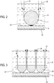
- FIG. figure 3 a matrix configuration of microbeads can be envisaged as illustrated in FIG. figure 3 where, in this example, a hemisphere matrix 21 is shown.
- the hemisphere matrix intended to be arranged in a measuring beam 23 within one of the optical metrology systems represented in FIG. figure 1 is included in an immersion medium 21.
- the refractive index of the medium 21 is less than that of the microbead 20.
- This immersion layer 21 is disposed on the surface 22 of the object 6 to be measured, for example a substrate, itself placed on a support 24.
- the microbead 7 then collects the reflected beam or diffused by the surface 22 of the object 6.
- This matrix arrangement of microbeads is particularly suitable with the use of a matrix of Mirau interferometers due to the small footprint, and it allows to increase the field of view while maintaining a similar acquisition rate.
- the raw signal 30a of the measured phase modulo 2 ⁇ is cut into an area of interest 30b of the object in order to limit the edge effects.
- the phase image is then unfolded 30c (unwrapping English) in two dimensions and then adjusted 30d (English surface fitting ) to remove the effects of aberrations.
- This image thus treated is then converted into a 30th height distribution.
- a dedicated program then makes it possible, from this distribution of height, to draw 30f profiles of the surface.
Landscapes
- Physics & Mathematics (AREA)
- General Physics & Mathematics (AREA)
- Optics & Photonics (AREA)
- Chemical & Material Sciences (AREA)
- Analytical Chemistry (AREA)
- Engineering & Computer Science (AREA)
- Multimedia (AREA)
- Computer Vision & Pattern Recognition (AREA)
- Instruments For Measurement Of Length By Optical Means (AREA)
Abstract
Système de métrologie optique en super résolution pour délivrer des informations sur la topographie de surface d'un échantillon ou objet (6) à l'échelle nanométrique en champ lointain, comprenant une source lumineuse (2), un interféromètre (1a, 1b, 1c, 1d) comprenant un bras de référence intégrant une microbille (9) et un miroir (10), un bras objet intégrant une microbille (7) similaire à ladite microbille (9) et disposée à proximité immédiate de la surface (22) de l'objet (6), des moyens récepteurs (5) pour capter des figures d'interférence, et des moyens pour traiter ces figures d'interférence de façon à produire les informations de topographie de surface. La source lumineuse (2) est cohérente ou partiellement cohérente temporellement. L'interféromètre et les moyens de traitement des figures d'interférence sont agencés pour reconstruire la surface de l'objet (6) par interférométrie à décalage de phase.Super-resolution optical metrology system for providing surface topography information of a sample or object (6) at the far-field nanometer scale, comprising a light source (2), an interferometer (1a, 1b, 1c , 1d) comprising a reference arm incorporating a microbead (9) and a mirror (10), an object arm incorporating a microbead (7) similar to said microbead (9) and arranged in close proximity to the surface (22) of the microbead (9). object (6), receiving means (5) for capturing interference patterns, and means for processing said interference patterns to produce the surface topography information. The light source (2) is coherent or partially temporally coherent. The interferometer and the processing means of the interference figures are arranged to reconstruct the surface of the object (6) by phase shift interferometry.
Description
La présente invention concerne un système et un procédé de métrologie optique en super résolution pour délivrer des informations sur la topographie de surface d'un échantillon à l'échelle nanométrique en champ lointain. Elle vise également un procédé de métrologie mis en oeuvre dans ce système.The present invention relates to a super resolution optical metrology system and method for providing surface topography information of a nanoscale sample in the far field. It also aims a metrology process implemented in this system.
Ce système et ce procédé visent notamment la profilométrie optique à super résolution. Son intérêt concerne la résolution spatiale nanométrique, au-delà de la limite de diffraction, obtenue dans les trois directions de l'espace.This system and this method particularly aim at super-resolution optical profilometry. His interest concerns the nanometric spatial resolution, beyond the diffraction limit, obtained in the three directions of space.
Un profilomètre optique est un instrument de métrologie sans contact permettant de reconstruire la topographie de surface d'un objet. Il existe plusieurs techniques de profilométrie optique telles que la microscopie confocale, la projection de lumière structurée et la microscopie interférométrique.An optical profilometer is a non-contact metrology instrument used to reconstruct the surface topography of an object. There are several optical profilometry techniques such as confocal microscopy, structured light projection and interferometric microscopy.
Le principe de l'interférométrie optique est semblable à celui de l'échographie acoustique car elle permet de reconstruire l'information de profondeur d'un objet en mesurant le temps de vol d'une onde réfléchie par une jonction entre deux matériaux de différents indices de cet objet. En d'autres termes, en échographie, l'onde émise par le transducteur est réfléchie par une jonction et est ensuite collectée par un récepteur. La durée entre l'émission et la réception est appelée temps de vol. En faisant le lien entre vitesse, temps et distance, on peut alors retrouver la position relative de la jonction. En interférométrie, c'est la même idée ; c'est-à-dire mesurer le temps de vol. En revanche, la vitesse de la lumière étant nettement supérieure à la vitesse du son, aucun capteur, à l'heure actuelle, n'est capable de mesurer cette durée. Cette technique nécessite donc une configuration plus complexe en ajoutant par exemple un bras de référence. En interférométrie, le signal enregistré par le récepteur (une image d'intensité) est appelé figure d'interférence qui est porteuse d'information de différence de chemin optique. Le récepteur est en général une matrice CCD (de l'anglais Charge Coupled Device) ou CMOS (de l'anglais Complementary Metal Oxide Semiconductor). En mesurant la différence de chemin optique entre l'onde de référence (qui est réfléchie par un miroir) et l'onde réfléchie par la jonction de l'objet, on peut alors remonter à l'information de hauteur.The principle of optical interferometry is similar to that of acoustic echography because it allows reconstructing the depth information of an object by measuring the flight time of a wave reflected by a junction between two materials of different indices. of this object. In other words, in ultrasound, the wave emitted by the transducer is reflected by a junction and is then collected by a receiver. The duration between transmission and reception is called flight time. By making the link between speed, time and distance, we can then find the relative position of the junction. In interferometry, it's the same idea; that is to say measure the flight time. On the other hand, the speed of the light being much higher than the speed of the sound, no sensor, at the moment, is able to measure this duration. This technique therefore requires a more complex configuration by adding for example a reference arm. In interferometry, the signal recorded by the receiver (an intensity image) is called an interference pattern that carries optical path difference information. The receiver is generally a CCD ( Charge Coupled Device ) or CMOS (English Complementary Metal Oxide Semiconductor ) matrix. By measuring the optical path difference between the reference wave (which is reflected by a mirror) and the wave reflected by the junction of the object, we can then go back to the height information.
Un profilomètre interférométrique utilise donc ce principe pour reconstruire la topographie d'un objet. L'interférométrie regroupe deux principales méthodes de mesure qui reposent sur leur illumination. Aussi, afin de diversifier encore plus ces deux méthodes, il existe de multiples façons d'interpréter les résultats et de reconstruire la topographie.An interferometric profilometer therefore uses this principle to reconstruct the topography of an object. Interferometry brings together two main measurement methods based on their illumination. Also, to further diversify these two methods, there are multiple ways to interpret the results and reconstruct the topography.
La première méthode de profilométrie utilise une illumination temporellement cohérente. Elle comprend deux procédés pour reconstruire la topographie qui sont l'holographie numérique et l'interférométrie à décalage de phase.The first profilometry method uses a temporally coherent illumination. It comprises two methods for reconstructing the topography which are digital holography and phase shift interferometry.
En holographie numérique (de l'anglais digital holography), l'information de profondeur (ou de différence de chemin optique) sur chaque pixel dépend du déphasage entre l'onde de référence et l'onde objet. Le détecteur collecte la figure d'interférences. Puis, par des algorithmes basés sur la propagation des ondes et la transformée de Fourier, on retrouve le déphasage entre l'onde objet et l'onde de référence. La technique a l'avantage de ne nécessiter qu'une seule acquisition. En revanche, contrairement à l'interférométrie à décalage de phase, elle requiert une source cohérente spatialement et un procédé d'algorithme plus complexe.In digital holography ( holography ), the depth information (or optical path difference) on each pixel depends on the phase shift between the reference wave and the object wave. The detector collects the interference pattern. Then, by algorithms based on wave propagation and the Fourier transform, we find the phase shift between the object wave and the reference wave. The technique has the advantage of requiring only one acquisition. In contrast, unlike phase shift interferometry, it requires a spatially coherent source and a more complex algorithm method.
Dans l'interférométrie à décalage de phase (de l'anglais phase shifting interferometry), le déphasage entre l'onde objet et l'onde de référence est calculé à partir d'une série de figures d'interférences décalées en phase, permettant de retrouver la différence de chemin optique sur chaque pixel. Le décalage en phase s'applique en déplaçant axialement, d'une distance connue, l'objet ou le miroir de référence. Cette technique permet une très grande sensibilité axiale, typiquement inférieure à 1 nm.In phase shifting interferometry (phase shifting interferometry ), the phase difference between the object wave and the reference wave is calculated from a series of phase-shifted interference patterns, allowing find the optical path difference on each pixel. The phase shift is applied by moving axially, by a known distance, the reference object or mirror. This technique allows a very high axial sensitivity, typically less than 1 nm.
Ces deux techniques en lumière cohérente de métrologie optique sont actuellement peu utilisées pour la profilométrie optique car dépendantes du bruit de cohérence et des effets de tavelure et de chatoiement (en anglais, speckle) induits.These two techniques in coherent optical metrology light are currently little used for optical profilometry because they are dependent on the coherence noise and the scab and speckle effects induced.
En interférométrie cohérente, la fonction de cohérence est approximée à 1. Donc le terme de différence de chemin optique se retrouve donc dans le terme de phase. En revanche, la deuxième méthode de profilométrie utilise une illumination incohérente ou partiellement incohérente temporellement (c'est-à-dire une source lumineuse polychromatique, par exemple une lampe halogène ou une diode électroluminescente LED). Ici, le principe repose sur le fait que l'interaction entre deux ondes incohérentes ou partiellement incohérentes forme un signal d'interférence porté par un signal que l'on appelle la fonction de cohérence qui porte l'information de différence de chemin optique sur chaque pixel. Mathématiquement, cette fonction de cohérence est exprimée comme une transformée de Fourier du spectre de la source lumineuse. Plus étroit est le spectre (dans le cas d'une source monochromatique), plus large est la fonction de cohérence, et inversement.In coherent interferometry, the coherence function is approximated to 1. So the term optical path difference is therefore found in the phase term. On the other hand, the second profilometry method uses an incoherent or partially incoherent illumination temporally (that is to say a polychromatic light source, for example a halogen lamp or an LED light emitting diode). Here, the principle is based on the fact that the interaction between two incoherent or partially incoherent waves forms an interference signal carried by a signal which is called the coherence function which carries the optical path difference information on each pixel. Mathematically, this coherence function is expressed as a Fourier transform of the spectrum of the light source. The narrower the spectrum (in the case of a monochromatic source), the wider is the coherence function, and vice versa.
Ici, l'information de profondeur ne provient pas du terme de phase mais du terme de cohérence qui lui aussi porte l'information de différence de chemin optique sur chaque pixel. Le détecteur enregistre l'irradiance lumineuse sur chaque pixel qui est la somme des amplitudes des ondes objet et de référence, élevée au carré. En déplaçant axialement l'objet ou le miroir de référence, on obtient un interférogramme sur chaque pixel en fonction de la position de l'objet. Lorsque la différence de chemin optique entre le plan du miroir et la jonction de l'objet est nulle, la valeur de l'enveloppe des franges est maximale sur chaque pixel et un pic d'intensité apparait. En d'autres termes, en balayant la différence de chemin optique suivant l'axe optique, le procédé détecte ce pic de l'enveloppe par pixel puis permet de remonter à l'information de profondeur de l'objet.Here, the depth information does not come from the phase term but from the coherence term which also carries the optical path difference information on each pixel. The detector records the luminous irradiance on each pixel which is the sum of the magnitudes of the object and reference waves, squared. By axially moving the reference object or mirror, an interferogram is obtained on each pixel as a function of the position of the object. When the optical path difference between the plane of the mirror and the junction of the object is zero, the value of the envelope of the fringes is maximum on each pixel and a peak of intensity appears. In other words, by scanning the difference in optical path along the optical axis, the method detects this peak of the envelope per pixel and then goes back to the depth information of the object.
Cette technique est appelée interférométrie à lumière blanche ou CSI (de l'anglais Coherence Scanning Interferometry). Elle est utilisable aussi bien pour la reconstruction de surface (la topographie) mais aussi de volume (la tomographie). La largeur à mi-hauteur de la fonction de cohérence de la source est appelée longueur de cohérence et est un critère de résolution axiale. Plus grande est la largeur du spectre, meilleure est la résolution axiale. Le procédé permet d'obtenir une sensibilité axiale inférieure à la centaine de nanomètre par pas d'échantillonnage. Des procédés d'interpolations de l'enveloppe améliorent la sensibilité à la dizaine de nanomètres (en utilisant une interpolation mathématique) jusqu'à quelques nanomètres (en utilisant l'interpolation de phase) selon la rugosité de la surface.This technique is called white light interferometry or CSI ( Coherence Scanning Interferometry ). It can be used both for surface reconstruction (topography) but also for volume (tomography). The half-height width of the source coherence function is called the coherence length and is an axial resolution criterion. The larger the spectrum, the better the axial resolution. The method makes it possible to obtain an axial sensitivity of less than one hundred nanometers per sampling step. Envelope interpolation methods improve the sensitivity to ten nanometers (using mathematical interpolation) up to a few nanometers (using phase interpolation) depending on the roughness of the surface.
Cependant, la résolution latérale d'un profilomètre optique est limitée par la diffraction provenant principalement de l'objectif de microscope.However, the lateral resolution of an optical profilometer is limited by diffraction mainly from the microscope objective.
D'après le critère d'Abbe, la valeur théorique de la résolution en imagerie incohérente est de λ / (2n sin α) où λ est la longueur d'onde, α est le demi-angle du cône de détection du système optique et n l'indice de réfraction du milieu. La valeur de sin α étant inférieur à 1, la résolution est donc supérieure à λ / (2n). Récemment, de nouvelles méthodes expérimentales ont permis de dépasser cette limite en optique en utilisant le principe de l'émission stimulée ou des lentilles à indice de réfraction négatif. En revanche, ces méthodes ne peuvent s'appliquer à l'interférométrie plein champ.According to the Abbe criterion, the theoretical value of the incoherent imaging resolution is λ / (2 n sin α ) where λ is the wavelength, α is the half-angle of the detection cone of the optical system and n the refractive index of the medium. Since the value of sin α is less than 1, the resolution is greater than λ / (2 n ). Recently, new experimental methods have made it possible to exceed this limit in optics using the principle of stimulated emission or lenses with a negative refractive index. On the other hand, these methods can not be applied to full-field interferometry.
En
Ce phénomène s'applique à la résolution latérale, c'est-à-dire à l'imagerie 2D. En plaçant une microbille dans le bras objet d'un interféromètre de Linnik, il a été montré la possibilité de reconstruire en 3D un objet avec une grande résolution axiale et latérale. On peut notamment citer la publication de
Pour l'utilisation de microbilles en métrologie en super résolution à l'échelle nanométrique, on peut notamment citer les documents
Le but de la présente invention est de proposer un système de profilométrie optique en super résolution, en champ lointain et en illumination cohérente ou partiellement cohérente qui présente de meilleures performances que les procédés actuels précités, tant en termes de résolution axiale qu'en termes de sensibilité de mesure. La technique d'interférométrie à décalage de phase est utilisée pour retrouver la distribution de chemin optique de l'échantillon.The aim of the present invention is to propose a super-resolution, far-field and coherent or partially coherent optical profilometry system which has better performances than the current methods mentioned above, both in terms of axial resolution and in terms of measurement sensitivity. The phase shift interferometry technique is used to find the optical path distribution of the sample.
Cet objectif est atteint avec un système de métrologie optique en super résolution pour délivrer des informations sur la topographie de surface d'un échantillon ou objet à l'échelle nanométrique en champ lointain, comprenant une source lumineuse cohérente ou partiellement cohérente, un interféromètre comprenant un bras objet intégrant une microbille transparente et disposée à proximité immédiate de la surface de l'objet, un bras de référence intégrant un miroir, des moyens récepteurs pour capter des figures d'interférence, et des moyens pour traiter lesdites figures d'interférence de façon à produire lesdites informations de topographie de surface, ledit interféromètre et lesdits moyens de traitement des figures d'interférence étant agencés pour reconstruire la topographie de l'objet par interférométrie à décalage de phase.This objective is achieved with a super resolution optical metrology system for delivering information on the surface topography of a nanoscale sample or object in the far field, comprising a coherent or partially light source coherently, an interferometer comprising an object arm incorporating a transparent microbead and disposed in close proximity to the surface of the object, a reference arm incorporating a mirror, receiving means for capturing interference patterns, and means for processing said objects; interference patterns so as to produce said surface topography information, said interferometer and said interference figure processing means being arranged to reconstruct the topography of the object by phase shift interferometry.
Il est entendu que les microbilles mises en oeuvre dans le système de profilométrie selon l'invention peuvent être de forme sphérique, elliptique, hémisphérique et plus généralement de forme convexe.It is understood that the microbeads used in the profilometry system according to the invention may be spherical, elliptical, hemispherical and more generally convex.
La source lumineuse cohérente ou quasi-cohérente temporellement peut présenter une longueur d'onde dans l'infra-rouge, le visible ou le proche ultra-violet.The temporally coherent or quasi-coherent light source may have a wavelength in the infra-red, the visible or the near ultraviolet.
Dans une première forme de réalisation, l'interféromètre est agencé pour procurer des mesures en configuration réflective et peut être d'un type choisi parmi le groupe des interféromètres de Michelson (1a), de Twyman-Green (1b) et Mirau (1c).In a first embodiment, the interferometer is arranged to provide measurements in reflective configuration and may be of a type selected from the group of interferometers Michelson (1a), Twyman-Green (1b) and Mirau (1c) .
Dans une autre forme de réalisation, l'interféromètre peut être agencé pour procurer des mesures en une configuration transmissive et peut être du type Mach Zehnder (1d).In another embodiment, the interferometer may be arranged to provide measurements in a transmissive configuration and may be Mach Zehnder (1d).
Dans l'art antérieur, les microbilles sont déposées sur la surface de l'objet. Ceci peut endommager l'objet dans le cas par exemple des échantillons biologiques ou lorsque le matériau de l'objet a un coefficient de dureté plus faible que le matériau de la microbille. En positionnant la microbille à quelques nanomètres de la surface de l'objet, on peut assurer une mesure sans contact. Dans une forme avantageuse de l'invention, la microbille est donc maintenue hors de contact avec la surface de l'échantillon. La microbille est maintenue par un support (par exemple de type pointe mécanique, pince optique ou système de grille percée). Cette microbille peut aussi être maintenue au-dessus de la surface de l'échantillon par un bras micromanipulateur pourvu de moyens pour tenir ladite microbille ou encore par une pince optique. Dans un mode particulier de réalisation d'un système selon l'invention, la microbille est placée dans une micro-grille disposée au-dessus de la surface de l'échantillon et comportant des trous de diamètre sensiblement inférieur à celui de ladite microbille.In the prior art, the microbeads are deposited on the surface of the object. This can damage the object in the case for example biological samples or when the material of the object has a lower coefficient of hardness than the material of the microbead. By positioning the microbead a few nanometers away from the surface of the object, a non-contact measurement can be provided. In an advantageous form of the invention, the microbead is thus kept out of contact with the surface of the sample. The microbead is held by a support (for example mechanical tip type, optical clamp or pierced grid system). This microbead can also be held above the surface of the sample by a micromanipulator arm provided with means for holding said microbead or by an optical clamp. In a particular embodiment of a system according to the invention, the microbead is placed in a micro-grid disposed above the surface of the sample and having holes of diameter substantially less than that of said microbead.
Elle peut par exemple être placée dans un milieu gazeux, liquide ou solide et d'indice de réfraction inférieur à celui de ladite microbille, ou dans une couche transparente d'indice de réfraction inférieur à celui de ladite microbille et disposée sur la surface de l'échantillon.It may for example be placed in a gaseous medium, liquid or solid and of refractive index lower than that of said microbead, or in a transparent layer of refractive index lower than that of said microbead and disposed on the surface of the microbead. 'sample.
La microbille (de forme sphérique, elliptique, hémisphérique, convexe) peut être avantageusement agencée pour concentrer un faisceau lumineux (que l'on appelle communément le jet photonique) sur l'objet.The microbead (spherical, elliptical, hemispherical, convex) can be advantageously arranged to concentrate a light beam (commonly known as the photonic jet) on the object.
Dans un autre mode particulier de réalisation, le bras de référence intègre en outre une microbille similaire à la microbille du bras objet, ladite microbille du bras de référence étant disposée pour compenser la dispersion.In another particular embodiment, the reference arm also incorporates a microbead similar to the microbead of the object arm, said microbead of the reference arm being arranged to compensate for the dispersion.
On peut aussi prévoir un agencement des microbilles selon une configuration matricielle translatable permettant de reconstruire un plus grand champ de vue.It is also possible to provide an arrangement of the microbeads in a translatable matrix configuration making it possible to reconstruct a larger field of view.
Suivant un autre aspect de l'invention, il est proposé un procédé de profilométrie optique en super résolution pour délivrer des informations sur la topographie de surface d'un échantillon à l'échelle nanométrique en champ lointain, mis en oeuvre dans un système de métrologie optique selon l'invention, ledit système intégrant un interféromètre comprenant un bras objet pourvue d'une microbille disposée à proximité immédiate de la surface de l'échantillon et agencé pour procurer des figures d'interférence. Le procédé selon l'invention comprend :
- une illumination de ladite surface via la microbille, par exemple de forme sphérique, elliptique, hémisphérique, convexe, par une source lumineuse cohérente ou quasi-cohérente temporellement avec une longueur d'onde dans le visible ou l'ultra-violet ou l'infrarouge, et
- un traitement desdites figures d'interférence pour reconstruire la surface de l'échantillon par interférométrie à décalage de phase.
- an illumination of said surface via the microbead, for example spherical, elliptical, hemispherical, convex, by a light source coherent or quasi-coherent temporally with a wavelength in the visible or ultraviolet or infrared , and
- processing said interference patterns to reconstruct the surface of the sample by phase shift interferometry.
Il peut en outre avantageusement comprendre une concentration d'un faisceau lumineux sur l'objet (jet photonique), et être agencé pour procurer des mesures interférométriques en configuration réflective.It can also advantageously comprise a concentration of a light beam on the object (photonic jet), and be arranged to provide interferometric measurements in reflective configuration.
Dans une forme particulière de mise en oeuvre du procédé de métrologie optique selon l'invention, le traitement des figures d'interférence comprend :
- Une production, à partir de figures d'interférence, d'un signal brut de la phase mesurée modulo 2π,
- Un découpage dudit signal brut de phase en une zone d'intérêt de l'échantillon de façon à limiter des effets de bord,
- Un dépliement de l'image de phase modulo 2π ainsi obtenue en deux dimensions,
- Un ajustement de ladite image de phase ainsi dépliée, de façon à supprimer des effets d'aberrations,
- Une conversion de ladite image de phase ainsi dépliée puis ajustée, en une distribution de hauteur, et
- Un traitement de ladite distribution de hauteur pour tracer des profils de surface dudit échantillon.
- A production, from interference figures, of a raw signal of the measured phase modulo 2π,
- A division of said raw phase signal into an area of interest of the sample so as to limit edge effects,
- An unfolding of the modulo 2π phase image thus obtained in two dimensions,
- An adjustment of said phase image thus unfolded, so as to eliminate effects of aberrations,
- A conversion of said phase image thus unfolded and then adjusted, into a height distribution, and
- Processing said pitch distribution to plot surface profiles of said sample.
D'autres avantages et particularités de l'invention apparaîtront à la lecture de la description détaillée de mises en oeuvre et de modes de réalisation nullement limitatifs, et des dessins annexés suivants :
- la
figure 1 illustre schématiquement quatre configurations optiques utilisées en réflexion et une configuration optique utilisée en transmission, pour un système de métrologie selon l'invention, - la
figure 2 illustre schématiquement un dispositif de positionnement d'une microbille par rapport à la surface d'un échantillon, - la
figure 3 illustre schématiquement un arrangement matriciel de microbilles (dans ce cas de type hémisphérique), et - la
figure 4 illustre schématiquement une succession d'étapes mises en oeuvre dans le procédé de métrologie optique selon l'invention.
- the
figure 1 schematically illustrates four optical configurations used in reflection and an optical configuration used in transmission, for a metrology system according to the invention, - the
figure 2 schematically illustrates a device for positioning a microbead with respect to the surface of a sample, - the
figure 3 schematically illustrates a matrix arrangement of microbeads (in this case hemispherical type), and - the
figure 4 schematically illustrates a succession of steps implemented in the optical metrology method according to the invention.
Ces modes de réalisation étant nullement limitatifs, on pourra notamment considérer des variantes de l'invention ne comprenant qu'une sélection de caractéristiques décrites ou illustrées par la suite isolées des autres caractéristiques décrites ou illustrées (même si cette sélection est isolée au sein d'une phase comprenant ces autres caractéristiques), si cette sélection de caractéristiques est suffisante pour conférer un avantage technique ou pour différencier l'invention par rapport à l'état de la technique antérieure. Cette sélection comprend au moins une caractéristique de préférence fonctionnelle sans détails structurels, et/ou avec seulement une partie des détails structurels si cette partie uniquement est suffisante pour conférer un avantage technique ou à différencier l'invention par rapport à l'état de la technique antérieure.These embodiments being in no way limiting, it will be possible to consider variants of the invention comprising only a selection of characteristics described or illustrated subsequently isolated from the other characteristics described or illustrated (even if this selection is isolated within a phase comprising these other characteristics), if this selection of characteristics is sufficient to confer a technical advantage or to differentiate the invention from the state of the prior art. This selection comprises at least one preferably functional characteristic without structural details, and / or with only a part of the structural details if this part alone is sufficient to confer a technical advantage or to differentiate the invention from the state of the art. earlier.
En référence à la
Les composants communs à ces quatre variantes de réalisation sont repérés dans la suite avec des références identiques.The components common to these four embodiments are identified in the following with identical references.
La configuration de type Michelson 1a requiert une partie illumination comprenant une source 2 cohérente ou partiellement cohérente temporellement, un collimateur et un séparateur de faisceau 3, et un partie imagerie comprenant l'interféromètre de Michelson, une lentille tube 4, un détecteur 5 et un dispositif 8 de traitement de ces figures d'interférence en vue de générer des profils de surface d'un objet ou échantillon 6.The Michelson type configuration 1a requires an illumination part comprising a
Un assemblage (non représenté en
Le détecteur 5 capte des figures d'interférence produites par l'interférence d'un faisceau objet issu du bras objet et d'un faisceau de référence provenant du bras de référence, et un dispositif 8 traite ces figures d'interférence en vue de générer des profils de surface de l'échantillon 6.The
La lentille tube 4 est disposée en sortie du séparateur de faisceau 3 pour faire converger les deux faisceaux de mesure et de référence en interférence vers le détecteur 5, tandis que la seconde lentille 11 est disposée entre le premier dispositif séparateur 3 et le second dispositif séparateur 12 pour faire converger le faisceau d'illumination vers l'objet 6 à mesurer.The
L'ouverture numérique de la lentille 11 est en pratique limitée par sa distance de travail et donc est généralement inférieure à 0.3. Avec une microbille de diamètre supérieure à 30 µm, ceci permet donc d'obtenir un grand champ de vue.The numerical aperture of the
La configuration Twyman-Green 1b représentée en
Dans l'interféromètre de Twyman-Green, les bras de référence et objet sont perpendiculaires entre eux et couplés par un séparateur de faisceau 12. Les fractions du faisceau sont incidentes sur deux lentilles convergentes ou deux assemblages de lentilles (une dans chaque bras) 13 et 14. Une partie du faisceau est transmise dans le bras de référence. Le faisceau est alors focalisé par la lentille 14 et la microbille ou une matrice de microbilles 9 (de forme sphérique, elliptique, hémisphérique, convexe) sur le miroir de référence 10 et réfléchi par ce dernier. La microbille 9 est en contact ou non sur le miroir 10. L'onde réfléchie est collectée par la microbille 9 puis la lentille 14. La seconde partie du faisceau est réfléchie par le séparateur 12 puis dirigée dans le bras objet de l'interféromètre. La seconde lentille 13 focalise le faisceau sur la surface de l'objet 6 à caractériser en mode réflexion, via une microbille 7 similaire à la microbille 9 du bras de référence et disposée à proximité immédiate de cet objet. L'onde est alors réfléchie ou diffusée par la surface de l'objet 6 puis collectée via la microbille 7 par la lentille 13. Comme l'onde de référence, l'onde objet est transmise par la lentille tube 4 puis imagée sur le détecteur 5.In the Twyman-Green interferometer, the reference and object arms are perpendicular to each other and coupled by a separator of
Le détecteur 5 capte des figures d'interférence produites par l'interférence d'un faisceau objet issu du bras objet et d'un faisceau de référence provenant du bras de référence, et un dispositif 8 traite ces figures d'interférence en vue de générer des profils de surface de l'échantillon 6.The
La lentille tube 4 est disposée en sortie du séparateur 12 pour faire converger les deux faisceaux de mesure et de référence en interférence vers le détecteur 5.The
L'ouverture numérique des deux lentilles identiques 13 et 14 n'est en pratique pas limitée par sa distance de travail et donc permet de faire l'acquisition avec une grande résolution latérale. L'architecture de Twyman-Green présente l'intérêt d'un compromis entre résolution latérale et champ de vue.The numerical aperture of the two
La configuration Mirau 1c représentée en
Dans l'interféromètre de Mirau, les bras de référence et objet sont parallèles entre eux. Le faisceau incident sur une lentille convergente ou un assemblage de lentilles 11 est séparé en fractions par un séparateur de faisceau 12 et orienté dans bras de référence et le bras objet. Le bras de référence comprend une microbille ou une matrice de microbilles 9 (de forme sphérique, elliptique, hémisphérique, convexe) et un miroir 10. La microbille est en contact ou non sur le miroir. Le bras objet comprend une microbille ou une matrice de microbilles 7 similaire à la microbille du bras de référence, et l'objet 6 à caractériser en mode réflexion.In the Mirau interferometer, the reference and object arms are parallel to each other. The incident beam on a converging lens or a
Le détecteur 5 capte des figures d'interférence produites par l'interférence d'un faisceau objet issu du bras objet et d'un faisceau de référence provenant du bras de référence, et un dispositif 8 traite ces figures d'interférence en vue de générer des profils de surface de l'échantillon 6.The
La lentille tube 4 est disposée en sortie du séparateur de faisceau 3 pour faire converger les deux faisceaux de mesure et de référence en interférence vers le détecteur 5, tandis que la seconde lentille 11 est disposée entre le premier dispositif séparateur 3 et le second dispositif séparateur 12 pour faire converger le faisceau d'illumination vers l'objet 6 à mesurer et le miroir de référence 10.The
L'ouverture numérique de la lentille 11 est en pratique limitée par sa distance de travail et donc est généralement inférieure à 0.5. Avec une microbille de diamètre supérieur à 30 µm, ceci permet donc d'obtenir un grand champ de vue.The numerical aperture of the
On va maintenant décrire, en référence à la
Une mesure en transmission permet de remonter à la différence de chemin optique induit par l'objet traversé. En connaissant l'indice de réfraction de l'objet, on retrouve la hauteur géométrique de l'objet, et vice-et-versa.A measurement in transmission makes it possible to go back to the difference in optical path induced by the crossed object. Knowing the refractive index of the object, we find the geometric height of the object, and vice-versa.
Le faisceau lumineux provenant d'une source cohérente ou partiellement cohérente 2 est divisé en deux par un séparateur de faisceau 12. Le faisceau transmis par le séparateur 12, appelé faisceau objet, passe au travers de d'un objet ou échantillon 6, après être éventuellement focalisé par une lentille optionnelle 15 qui est prévue pour concentrer l'énergie de la lumière sur le champ de vue souhaité et donc récolter plus de lumière par la suite.The light beam originating from a coherent or partially
Une microbille 7 puis une lentille 11 collectent le faisceau diffusé par l'objet 6. Un miroir 16 dirige ce faisceau objet sur un détecteur 5 en passant au travers d'un séparateur de faisceau 18 et une lentille tube ou lentille relais 4.A
Le faisceau réfléchi par le séparateur de faisceau 12, appelé faisceau de référence, est dirigé par un miroir 17 vers le séparateur de faisceau 18 où il est de nouveau dirigé sur le détecteur 5 via la lentille tube 4.The beam reflected by the
Le dispositif 8 de traitement des figures d'interférence permet ensuite de retrouver la distribution latérale (c'est-à-dire suivant X et Y) du chemin optique de l'objet, notamment des informations d'indice de réfraction et de hauteur géométrique.The
Il est important de noter que, selon l'invention, dans les systèmes de métrologie optique qui viennent d'être décrits, on peut modifier la polarisation via des polariseurs et des lames à retard, l'uniformité de l'éclairage de l'objet via un système d'éclairage, et les angles des rayons incidents sur l'échantillon.It is important to note that, according to the invention, in the optical metrology systems which have just been described, it is possible to modify the polarization via polarisers and delay plates, the uniformity of the illumination of the object via a lighting system, and the angles of the rays incident on the sample.
Les microbilles 7, 9, qui sont mises en oeuvre dans les systèmes 1a, 1b, 1c et 1d de métrologie optique selon l'invention décrits ci-dessus en référence à la
Dans les différents cas qui viennent d'être décrits, la grandeur mesurable dans un système de métrologie optique selon l'invention est une image ou une série d'images en intensité en deux dimensions que l'on appelle plus communément figure d'interférence. Les informations retrouvées sont alors la topographie de surface de l'objet via l'interférométrie à décalage de phase. Cette méthode à décalage de phase est plus rapide que la méthode connue de détection du pic de la fonction de cohérence car elle nécessite moins d'acquisitions, et apporte une meilleure résolution axiale. Quatre images suffisent à reconstruire la topographie de surface de l'objet. Le déphasage calculé entre l'onde de référence et l'onde objet (interprétée comme un retard de l'onde) permet de retrouver les reliefs de surface, c'est-à-dire la topographie, via une formule classique prenant en compte la dispersion de la microbille.In the various cases which have just been described, the measurable quantity in an optical metrology system according to the invention is a two-dimensional image or series of intensity images which is more commonly referred to as an interference figure. The information found is then the surface topography of the object via phase shift interferometry. This phase shift method is faster than the known method of detecting the peak of the coherence function because it requires fewer acquisitions, and provides better axial resolution. Four images are enough to reconstruct the surface topography of the object. The phase shift calculated between the reference wave and the object wave (interpreted as a delay of the wave) makes it possible to find the surface reliefs, that is to say the topography, via a conventional formula taking into account the dispersion of the microbead.
Pour les différents modes de réalisation qui viennent d'être décrits, la source lumineuse 2 doit fournir une grande cohérence. De plus, les simulations numériques ainsi que les mesures expérimentales ont montré que l'utilisation d'une source lumineuse avec une faible longueur d'onde apporte une plus grande résolution latérale. Par exemple, une source de lumière bleue et proche UV apporte une plus grande résolution latérale.For the different embodiments that have just been described, the
La source lumineuse 2 peut être :
- cohérente, par exemple une source laser avec une longueur de cohérence du mètre,
- quasi-cohérente, par exemple une diode laser avec une longueur de cohérence du centimètre,
- partiellement cohérente, par exemple une diode super-luminescente avec une longueur de cohérence de la centaine de micromètres,
- partiellement incohérente, par exemple une diode électroluminescente avec une longueur de cohérence de la dizaine de micromètres,
- filtrée étroitement en longueurs d'onde, par exemple un super-continuum et un filtre,
- dans tous les cas, de préférence avec une longueur d'onde courte ou avec un spectre centré sur une longueur d'onde courte, dans le vert, le bleu, voire l'ultra-violet, par exemple une LED bleue à 450 nm.
- coherent, for example a laser source with a coherence length of the meter,
- quasi-coherent, for example a laser diode with a centimeter coherence length,
- partially coherent, for example a super-luminescent diode with a coherence length of about one hundred micrometers,
- partially incoherent, for example an electroluminescent diode with a coherence length of about ten micrometers,
- filtered tightly in wavelengths, for example a super-continuum and a filter,
- in all cases, preferably with a short wavelength or with a spectrum centered on a short wavelength, in the green, blue or even ultraviolet, for example a blue LED at 450 nm.
Les performances d'un profilomètre à super résolution selon l'invention dépendent de plusieurs paramètres tels que la combinaison entre la lentille ou l'assemblage de lentilles de collection et la microbille, et la longueur d'onde. Il a été montré qu'un interféromètre de configuration Twyman-Green 1b décrit ci-dessus en référence à la
Dans l'exemple de réalisation illustré en
Le contraste d'indice à prendre en compte pour l'évaluation des performances d'imagerie est celui entre la microbille 20 et la couche 21. Par exemple, la microbille 20 peut être réalisée en titanate de baryum et incluse dans une couche 21 en PDMS. On peut aussi prévoir que la microbille soit placée dans une micro-grille percée à un diamètre légèrement inférieur à la taille des microbilles afin de les maintenir, ou bien maintenue par un bras micro manipulateur avec une pince ou un autre système d'adhésion, ou encore maintenue par une pince optique.The contrast of index to be taken into account for the evaluation of the imaging performance is that between the
De plus, une configuration matricielle de microbilles peut être envisagée comme illustré dans la
Cet agencement matriciel de microbilles est particulièrement adapté avec l'utilisation d'une matrice d'interféromètres de Mirau du fait de l'encombrement réduit, et il permet d'augmenter le champ de vue tout en conservant une cadence d'acquisition similaire.This matrix arrangement of microbeads is particularly suitable with the use of a matrix of Mirau interferometers due to the small footprint, and it allows to increase the field of view while maintaining a similar acquisition rate.
On va maintenant décrire, en référence à la
Le signal brut 30a de la phase mesurée modulo 2π est découpé en une zone d'intérêt 30b de l'objet afin de limiter les effets de bords. L'image de phase est ensuite dépliée 30c (de l'anglais unwrapping) en deux dimensions puis ajustée 30d (de l'anglais surface fitting) afin de supprimer les effets d'aberrations.The
Cette image ainsi traitée est ensuite convertie en une distribution de hauteur 30e. Un programme dédié permet alors, à partir de cette distribution de hauteur, de tracer des profils 30f de la surface.This image thus treated is then converted into a 30th height distribution. A dedicated program then makes it possible, from this distribution of height, to draw 30f profiles of the surface.
Bien sûr, l'invention n'est pas limitée aux exemples qui viennent d'être décrits et de nombreux aménagements peuvent être apportés à ces exemples sans sortir du cadre de l'invention. Bien entendu, les différentes caractéristiques, formes, variantes et modes de réalisation de l'invention peuvent être associées les unes avec les autres selon diverses combinaisons dans la mesure où elles ne sont pas incompatibles ou exclusives les unes des autres. En particulier toutes les variantes et modes de réalisation décrits précédemment sont combinables entre eux.Of course, the invention is not limited to the examples that have just been described and many adjustments can be made to these examples without departing from the scope of the invention. Of course, the various features, shapes, variants and embodiments of the invention can be associated with each other in various combinations to the extent that they are not incompatible or exclusive of each other. In particular all the variants and embodiments described above are combinable with each other.
Claims (23)
ledit interféromètre (1a, 1b, 1c, 1d) et lesdits moyens (8) de traitement des figures d'interférence étant agencés pour reconstruire la topographie de l'objet (6) par interférométrie à décalage de phase.Super-resolution optical metrology system for providing surface topography information of a sample or object (6) at the far-field nanoscale, comprising a coherent or partially coherent light source (2), an interferometer (1a , 1b, 1c, 1d) comprising an object arm incorporating a transparent microbead (7) and disposed in close proximity to the surface of the object (6), a reference arm incorporating a mirror (10), receiving means (5) ) for capturing interference patterns, and means (8) for processing said interference patterns to produce said surface topography information,
said interferometer (1a, 1b, 1c, 1d) and said means (8) for processing the interference patterns being arranged to reconstruct the topography of the object (6) by phase shift interferometry.
ce procédé comprenant :
this process comprising:
Priority Applications (6)
| Application Number | Priority Date | Filing Date | Title |
|---|---|---|---|
| EP17166026.9A EP3388779A1 (en) | 2017-04-11 | 2017-04-11 | System and method for nanometric super-resolution optical metrology in the far-field |
| US16/604,942 US20200103224A1 (en) | 2017-04-11 | 2018-04-11 | System and method for super-resolution full-field optical metrology on the far-field nanometre scale |
| PCT/EP2018/059306 WO2018189250A1 (en) | 2017-04-11 | 2018-04-11 | System and method for super-resolution full-field optical metrology on the far-field nanometre scale |
| KR1020197029451A KR20190138788A (en) | 2017-04-11 | 2018-04-11 | Systems and methods for ultra-resolution full-length optical metrology on long-range nanometer scales |
| EP18720128.0A EP3610222A1 (en) | 2017-04-11 | 2018-04-11 | System and method for super-resolution full-field optical metrology on the far-field nanometre scale |
| CN201880023855.2A CN110770534A (en) | 2017-04-11 | 2018-04-11 | Far-field nanoscale super-resolution full-field optical metering system and method |
Applications Claiming Priority (1)
| Application Number | Priority Date | Filing Date | Title |
|---|---|---|---|
| EP17166026.9A EP3388779A1 (en) | 2017-04-11 | 2017-04-11 | System and method for nanometric super-resolution optical metrology in the far-field |
Publications (1)
| Publication Number | Publication Date |
|---|---|
| EP3388779A1 true EP3388779A1 (en) | 2018-10-17 |
Family
ID=58638672
Family Applications (2)
| Application Number | Title | Priority Date | Filing Date |
|---|---|---|---|
| EP17166026.9A Withdrawn EP3388779A1 (en) | 2017-04-11 | 2017-04-11 | System and method for nanometric super-resolution optical metrology in the far-field |
| EP18720128.0A Withdrawn EP3610222A1 (en) | 2017-04-11 | 2018-04-11 | System and method for super-resolution full-field optical metrology on the far-field nanometre scale |
Family Applications After (1)
| Application Number | Title | Priority Date | Filing Date |
|---|---|---|---|
| EP18720128.0A Withdrawn EP3610222A1 (en) | 2017-04-11 | 2018-04-11 | System and method for super-resolution full-field optical metrology on the far-field nanometre scale |
Country Status (5)
| Country | Link |
|---|---|
| US (1) | US20200103224A1 (en) |
| EP (2) | EP3388779A1 (en) |
| KR (1) | KR20190138788A (en) |
| CN (1) | CN110770534A (en) |
| WO (1) | WO2018189250A1 (en) |
Cited By (1)
| Publication number | Priority date | Publication date | Assignee | Title |
|---|---|---|---|---|
| CN109828365A (en) * | 2019-02-25 | 2019-05-31 | 南京理工大学 | Mirau type super-resolution interferes microcobjective |
Families Citing this family (5)
| Publication number | Priority date | Publication date | Assignee | Title |
|---|---|---|---|---|
| FR3101702B1 (en) * | 2019-10-07 | 2021-11-19 | Fogale Nanotech | Device and method for imaging and interferometry measurements |
| KR20220021327A (en) * | 2020-08-13 | 2022-02-22 | 삼성전자주식회사 | Spectroscopic measuring apparatus and method, and method for fabricating semiconductor device using the measuring method |
| TWI805038B (en) * | 2021-10-21 | 2023-06-11 | 財團法人工業技術研究院 | Holographic microscope and using method thereof |
| CN116362977B (en) * | 2021-12-23 | 2023-12-22 | 荣耀终端有限公司 | Method and device for eliminating interference patterns in image |
| CN117647470A (en) * | 2024-01-29 | 2024-03-05 | 之江实验室 | Device for measuring far field of scattered field based on suspended optical tweezers and reciprocity theorem and application thereof |
Citations (7)
| Publication number | Priority date | Publication date | Assignee | Title |
|---|---|---|---|---|
| US6445453B1 (en) * | 1999-08-02 | 2002-09-03 | Zetetic Institute | Scanning interferometric near-field confocal microscopy |
| US20090182528A1 (en) * | 2007-12-14 | 2009-07-16 | De Groot Peter | Analyzing surface structure using scanning interferometry |
| CN102735878A (en) | 2012-06-25 | 2012-10-17 | 浙江大学 | Super-resolution microscopic imaging method and system based on microcantilever and microsphere combined probe |
| WO2013043818A1 (en) | 2011-09-23 | 2013-03-28 | The Trustees Of Columbia University In The City Of New York | Microsphere superlens based superresolution imaging platform |
| CN103823353A (en) | 2014-03-10 | 2014-05-28 | 北京工业大学 | Sub-wavelength super-resolution digital holographic imaging system based on microspheres |
| US20150276864A1 (en) * | 2012-10-12 | 2015-10-01 | Trustees Of Boston University | Dual-phase interferometry for charge modulation mapping in ics |
| WO2017098079A1 (en) * | 2015-12-11 | 2017-06-15 | University Of Helsinki | Properties of a surface and subsurface structures with white light interferometry using photonic jets |
Family Cites Families (3)
| Publication number | Priority date | Publication date | Assignee | Title |
|---|---|---|---|---|
| CN101256070B (en) * | 2008-04-17 | 2010-09-29 | 复旦大学 | Method for lossless measuring shape parameter of atomic force microscope probe |
| CN101498631B (en) * | 2009-03-06 | 2012-11-14 | 中国科学院力学研究所 | Production method for surface moire optical grating of tensile specimen |
| CN106052947B (en) * | 2016-07-13 | 2018-08-31 | 中国工程物理研究院激光聚变研究中心 | The device and method of mixed gas pressure intensity in a kind of measurement transparent beads |
-
2017
- 2017-04-11 EP EP17166026.9A patent/EP3388779A1/en not_active Withdrawn
-
2018
- 2018-04-11 CN CN201880023855.2A patent/CN110770534A/en active Pending
- 2018-04-11 EP EP18720128.0A patent/EP3610222A1/en not_active Withdrawn
- 2018-04-11 KR KR1020197029451A patent/KR20190138788A/en unknown
- 2018-04-11 US US16/604,942 patent/US20200103224A1/en not_active Abandoned
- 2018-04-11 WO PCT/EP2018/059306 patent/WO2018189250A1/en unknown
Patent Citations (7)
| Publication number | Priority date | Publication date | Assignee | Title |
|---|---|---|---|---|
| US6445453B1 (en) * | 1999-08-02 | 2002-09-03 | Zetetic Institute | Scanning interferometric near-field confocal microscopy |
| US20090182528A1 (en) * | 2007-12-14 | 2009-07-16 | De Groot Peter | Analyzing surface structure using scanning interferometry |
| WO2013043818A1 (en) | 2011-09-23 | 2013-03-28 | The Trustees Of Columbia University In The City Of New York | Microsphere superlens based superresolution imaging platform |
| CN102735878A (en) | 2012-06-25 | 2012-10-17 | 浙江大学 | Super-resolution microscopic imaging method and system based on microcantilever and microsphere combined probe |
| US20150276864A1 (en) * | 2012-10-12 | 2015-10-01 | Trustees Of Boston University | Dual-phase interferometry for charge modulation mapping in ics |
| CN103823353A (en) | 2014-03-10 | 2014-05-28 | 北京工业大学 | Sub-wavelength super-resolution digital holographic imaging system based on microspheres |
| WO2017098079A1 (en) * | 2015-12-11 | 2017-06-15 | University Of Helsinki | Properties of a surface and subsurface structures with white light interferometry using photonic jets |
Non-Patent Citations (5)
| Title |
|---|
| F. WANG ET AL., SCIENTIFIC REPORTS, vol. 6, 2016, pages 24703 |
| MOSTAFA AAKHTE ET AL: "Microsphere-assisted super-resolved Mirau digital holographic microscopy for cell identification", APPLIED OPTICS, vol. 56, no. 9, 9 January 2017 (2017-01-09), WASHINGTON, DC; US, pages D8, XP055406457, ISSN: 0003-6935, DOI: 10.1364/AO.56.0000D8 * |
| NATURE COMMUNICATIONS, vol. 2, 2011, pages 218 |
| STEPHANE PERRIN ET AL: "Microsphere-assisted phase-shifting profilometry", APPLIED OPTICS, vol. 56, no. 25, 1 September 2017 (2017-09-01), US, pages 7249, XP055406357, ISSN: 1559-128X, DOI: 10.1364/AO.56.007249 * |
| Z. WANG E, NATURE COMMUNICATIONS, vol. 2, 2011, pages 218 |
Cited By (2)
| Publication number | Priority date | Publication date | Assignee | Title |
|---|---|---|---|---|
| CN109828365A (en) * | 2019-02-25 | 2019-05-31 | 南京理工大学 | Mirau type super-resolution interferes microcobjective |
| CN109828365B (en) * | 2019-02-25 | 2021-05-04 | 南京理工大学 | Mirau type super-resolution interference microscope objective |
Also Published As
| Publication number | Publication date |
|---|---|
| CN110770534A (en) | 2020-02-07 |
| US20200103224A1 (en) | 2020-04-02 |
| EP3610222A1 (en) | 2020-02-19 |
| WO2018189250A1 (en) | 2018-10-18 |
| KR20190138788A (en) | 2019-12-16 |
Similar Documents
| Publication | Publication Date | Title |
|---|---|---|
| EP3388779A1 (en) | System and method for nanometric super-resolution optical metrology in the far-field | |
| EP3084345B1 (en) | Device and process of optical tomography | |
| WO2017108400A1 (en) | Device and method for measuring height in the presence of thin layers | |
| EP3980715A1 (en) | Device and method for measuring interfaces of an optical element | |
| EP0985902A1 (en) | Interferometric device for picking up optical subsurface reflexion and/or transmission characteristics of an object | |
| FR2959305A1 (en) | OPTICAL DEVICE AND METHOD FOR INSPECTING STRUCTURED OBJECTS. | |
| FR2960291A1 (en) | METHOD AND DEVICE FOR FULL-FIELD HIGH-RESOLUTION FIELD INTERFERENTIAL MICROSCOPY | |
| FR3026481A1 (en) | DEVICE AND METHOD FOR SURFACE PROFILOMETRY FOR CONTROLLING WAFERS DURING PROCESS | |
| FR2962531A1 (en) | METHOD AND DEVICE FOR THREE-DIMENSIONAL IMAGING BY FULL FIELD INTERFERENTIAL MICROSCOPY | |
| CA2617983A1 (en) | Tomographic imaging by an interferometric immersion microscope | |
| WO2009080998A2 (en) | High-resolution surface plasmon microscope with heterodyne interferometry in radial polarization mode | |
| FR3013128A1 (en) | DEVICE AND METHOD FOR THREE DIMENSIONAL FOCUSING FOR MICROSCOPE | |
| WO2011125033A1 (en) | Method for detecting clusters of biological particles | |
| EP4042098A1 (en) | Device and method for imaging and interferometry measurements | |
| WO2016050460A1 (en) | Diffraction microscope method and device | |
| EP3602201B1 (en) | Devices and methods for optical imaging by means of off-axis digital holography | |
| EP4214463A1 (en) | Device and method for measuring interfaces of an optical element | |
| EP2396644A2 (en) | High resolution surface plasmon microcope with heterodyne fiber interferometer | |
| EP2486391A1 (en) | Method and system for structural analysis of an object by measuring the wave front thereof | |
| EP3575774B1 (en) | Method for observing particles, in particular submicron particles | |
| WO2024069058A1 (en) | Optical device for self-referenced full-field temporal optical coherence tomography microscopic imaging, and associated facility and method | |
| CA3056969C (en) | Vibration measurement protection system | |
| WO2023057539A1 (en) | Method and device for measuring interfaces of an optical element |
Legal Events
| Date | Code | Title | Description |
|---|---|---|---|
| PUAI | Public reference made under article 153(3) epc to a published international application that has entered the european phase |
Free format text: ORIGINAL CODE: 0009012 |
|
| STAA | Information on the status of an ep patent application or granted ep patent |
Free format text: STATUS: THE APPLICATION HAS BEEN PUBLISHED |
|
| AK | Designated contracting states |
Kind code of ref document: A1 Designated state(s): AL AT BE BG CH CY CZ DE DK EE ES FI FR GB GR HR HU IE IS IT LI LT LU LV MC MK MT NL NO PL PT RO RS SE SI SK SM TR |
|
| AX | Request for extension of the european patent |
Extension state: BA ME |
|
| STAA | Information on the status of an ep patent application or granted ep patent |
Free format text: STATUS: THE APPLICATION IS DEEMED TO BE WITHDRAWN |
|
| 18D | Application deemed to be withdrawn |
Effective date: 20190418 |