EP3379121A1 - Solenoid valve for monitoring and controlling the fluid supply to a building installation, and device further comprising such a solenoid valve - Google Patents
Solenoid valve for monitoring and controlling the fluid supply to a building installation, and device further comprising such a solenoid valve Download PDFInfo
- Publication number
- EP3379121A1 EP3379121A1 EP18162236.6A EP18162236A EP3379121A1 EP 3379121 A1 EP3379121 A1 EP 3379121A1 EP 18162236 A EP18162236 A EP 18162236A EP 3379121 A1 EP3379121 A1 EP 3379121A1
- Authority
- EP
- European Patent Office
- Prior art keywords
- solenoid valve
- inlet
- fluid
- passage
- outlet
- Prior art date
- Legal status (The legal status is an assumption and is not a legal conclusion. Google has not performed a legal analysis and makes no representation as to the accuracy of the status listed.)
- Withdrawn
Links
- 239000012530 fluid Substances 0.000 title claims abstract description 67
- 238000009434 installation Methods 0.000 title claims abstract description 24
- 238000012544 monitoring process Methods 0.000 title claims abstract description 11
- 238000007789 sealing Methods 0.000 claims abstract description 6
- 238000001514 detection method Methods 0.000 claims description 7
- XLYOFNOQVPJJNP-UHFFFAOYSA-N water Substances O XLYOFNOQVPJJNP-UHFFFAOYSA-N 0.000 description 11
- 235000021183 entrée Nutrition 0.000 description 10
- 238000012806 monitoring device Methods 0.000 description 6
- 208000031968 Cadaver Diseases 0.000 description 3
- 238000009428 plumbing Methods 0.000 description 3
- 230000005540 biological transmission Effects 0.000 description 2
- 229940082150 encore Drugs 0.000 description 2
- 230000001960 triggered effect Effects 0.000 description 2
- 241001080024 Telles Species 0.000 description 1
- 238000012550 audit Methods 0.000 description 1
- 238000004883 computer application Methods 0.000 description 1
- 230000002950 deficient Effects 0.000 description 1
- 238000009792 diffusion process Methods 0.000 description 1
- 230000000694 effects Effects 0.000 description 1
- 238000005516 engineering process Methods 0.000 description 1
- 230000002262 irrigation Effects 0.000 description 1
- 238000003973 irrigation Methods 0.000 description 1
- 238000002955 isolation Methods 0.000 description 1
- 238000007726 management method Methods 0.000 description 1
- 239000000463 material Substances 0.000 description 1
- 239000012528 membrane Substances 0.000 description 1
- 230000002093 peripheral effect Effects 0.000 description 1
- 230000008054 signal transmission Effects 0.000 description 1
Images


Classifications
-
- E—FIXED CONSTRUCTIONS
- E03—WATER SUPPLY; SEWERAGE
- E03B—INSTALLATIONS OR METHODS FOR OBTAINING, COLLECTING, OR DISTRIBUTING WATER
- E03B7/00—Water main or service pipe systems
- E03B7/07—Arrangement of devices, e.g. filters, flow controls, measuring devices, siphons or valves, in the pipe systems
- E03B7/072—Arrangement of flowmeters
-
- E—FIXED CONSTRUCTIONS
- E03—WATER SUPPLY; SEWERAGE
- E03B—INSTALLATIONS OR METHODS FOR OBTAINING, COLLECTING, OR DISTRIBUTING WATER
- E03B7/00—Water main or service pipe systems
- E03B7/07—Arrangement of devices, e.g. filters, flow controls, measuring devices, siphons or valves, in the pipe systems
- E03B7/071—Arrangement of safety devices in domestic pipe systems, e.g. devices for automatic shut-off
-
- E—FIXED CONSTRUCTIONS
- E03—WATER SUPPLY; SEWERAGE
- E03B—INSTALLATIONS OR METHODS FOR OBTAINING, COLLECTING, OR DISTRIBUTING WATER
- E03B7/00—Water main or service pipe systems
- E03B7/07—Arrangement of devices, e.g. filters, flow controls, measuring devices, siphons or valves, in the pipe systems
- E03B7/075—Arrangement of devices for control of pressure or flow rate
-
- E—FIXED CONSTRUCTIONS
- E03—WATER SUPPLY; SEWERAGE
- E03B—INSTALLATIONS OR METHODS FOR OBTAINING, COLLECTING, OR DISTRIBUTING WATER
- E03B7/00—Water main or service pipe systems
- E03B7/07—Arrangement of devices, e.g. filters, flow controls, measuring devices, siphons or valves, in the pipe systems
- E03B7/078—Combined units with different devices; Arrangement of different devices with respect to each other
-
- F—MECHANICAL ENGINEERING; LIGHTING; HEATING; WEAPONS; BLASTING
- F16—ENGINEERING ELEMENTS AND UNITS; GENERAL MEASURES FOR PRODUCING AND MAINTAINING EFFECTIVE FUNCTIONING OF MACHINES OR INSTALLATIONS; THERMAL INSULATION IN GENERAL
- F16K—VALVES; TAPS; COCKS; ACTUATING-FLOATS; DEVICES FOR VENTING OR AERATING
- F16K31/00—Actuating devices; Operating means; Releasing devices
- F16K31/12—Actuating devices; Operating means; Releasing devices actuated by fluid
- F16K31/36—Actuating devices; Operating means; Releasing devices actuated by fluid in which fluid from the circuit is constantly supplied to the fluid motor
- F16K31/40—Actuating devices; Operating means; Releasing devices actuated by fluid in which fluid from the circuit is constantly supplied to the fluid motor with electrically-actuated member in the discharge of the motor
- F16K31/402—Actuating devices; Operating means; Releasing devices actuated by fluid in which fluid from the circuit is constantly supplied to the fluid motor with electrically-actuated member in the discharge of the motor acting on a diaphragm
-
- F—MECHANICAL ENGINEERING; LIGHTING; HEATING; WEAPONS; BLASTING
- F16—ENGINEERING ELEMENTS AND UNITS; GENERAL MEASURES FOR PRODUCING AND MAINTAINING EFFECTIVE FUNCTIONING OF MACHINES OR INSTALLATIONS; THERMAL INSULATION IN GENERAL
- F16K—VALVES; TAPS; COCKS; ACTUATING-FLOATS; DEVICES FOR VENTING OR AERATING
- F16K37/00—Special means in or on valves or other cut-off apparatus for indicating or recording operation thereof, or for enabling an alarm to be given
- F16K37/0025—Electrical or magnetic means
- F16K37/0041—Electrical or magnetic means for measuring valve parameters
-
- F—MECHANICAL ENGINEERING; LIGHTING; HEATING; WEAPONS; BLASTING
- F16—ENGINEERING ELEMENTS AND UNITS; GENERAL MEASURES FOR PRODUCING AND MAINTAINING EFFECTIVE FUNCTIONING OF MACHINES OR INSTALLATIONS; THERMAL INSULATION IN GENERAL
- F16K—VALVES; TAPS; COCKS; ACTUATING-FLOATS; DEVICES FOR VENTING OR AERATING
- F16K37/00—Special means in or on valves or other cut-off apparatus for indicating or recording operation thereof, or for enabling an alarm to be given
- F16K37/0025—Electrical or magnetic means
- F16K37/005—Electrical or magnetic means for measuring fluid parameters
-
- F—MECHANICAL ENGINEERING; LIGHTING; HEATING; WEAPONS; BLASTING
- F16—ENGINEERING ELEMENTS AND UNITS; GENERAL MEASURES FOR PRODUCING AND MAINTAINING EFFECTIVE FUNCTIONING OF MACHINES OR INSTALLATIONS; THERMAL INSULATION IN GENERAL
- F16L—PIPES; JOINTS OR FITTINGS FOR PIPES; SUPPORTS FOR PIPES, CABLES OR PROTECTIVE TUBING; MEANS FOR THERMAL INSULATION IN GENERAL
- F16L55/00—Devices or appurtenances for use in, or in connection with, pipes or pipe systems
- F16L55/10—Means for stopping flow from or in pipes or hoses
- F16L55/1022—Fluid cut-off devices automatically actuated
-
- G—PHYSICS
- G01—MEASURING; TESTING
- G01F—MEASURING VOLUME, VOLUME FLOW, MASS FLOW OR LIQUID LEVEL; METERING BY VOLUME
- G01F15/00—Details of, or accessories for, apparatus of groups G01F1/00 - G01F13/00 insofar as such details or appliances are not adapted to particular types of such apparatus
- G01F15/001—Means for regulating or setting the meter for a predetermined quantity
- G01F15/003—Means for regulating or setting the meter for a predetermined quantity using electromagnetic, electric or electronic means
-
- G—PHYSICS
- G01—MEASURING; TESTING
- G01F—MEASURING VOLUME, VOLUME FLOW, MASS FLOW OR LIQUID LEVEL; METERING BY VOLUME
- G01F15/00—Details of, or accessories for, apparatus of groups G01F1/00 - G01F13/00 insofar as such details or appliances are not adapted to particular types of such apparatus
- G01F15/005—Valves
-
- G—PHYSICS
- G01—MEASURING; TESTING
- G01F—MEASURING VOLUME, VOLUME FLOW, MASS FLOW OR LIQUID LEVEL; METERING BY VOLUME
- G01F15/00—Details of, or accessories for, apparatus of groups G01F1/00 - G01F13/00 insofar as such details or appliances are not adapted to particular types of such apparatus
- G01F15/06—Indicating or recording devices
- G01F15/065—Indicating or recording devices with transmission devices, e.g. mechanical
- G01F15/066—Indicating or recording devices with transmission devices, e.g. mechanical involving magnetic transmission devices
-
- G—PHYSICS
- G01—MEASURING; TESTING
- G01F—MEASURING VOLUME, VOLUME FLOW, MASS FLOW OR LIQUID LEVEL; METERING BY VOLUME
- G01F15/00—Details of, or accessories for, apparatus of groups G01F1/00 - G01F13/00 insofar as such details or appliances are not adapted to particular types of such apparatus
- G01F15/07—Integration to give total flow, e.g. using mechanically-operated integrating mechanism
- G01F15/075—Integration to give total flow, e.g. using mechanically-operated integrating mechanism using electrically-operated integrating means
-
- A—HUMAN NECESSITIES
- A01—AGRICULTURE; FORESTRY; ANIMAL HUSBANDRY; HUNTING; TRAPPING; FISHING
- A01G—HORTICULTURE; CULTIVATION OF VEGETABLES, FLOWERS, RICE, FRUIT, VINES, HOPS OR SEAWEED; FORESTRY; WATERING
- A01G25/00—Watering gardens, fields, sports grounds or the like
- A01G25/16—Control of watering
- A01G25/165—Cyclic operations, timing systems, timing valves, impulse operations
-
- G—PHYSICS
- G01—MEASURING; TESTING
- G01F—MEASURING VOLUME, VOLUME FLOW, MASS FLOW OR LIQUID LEVEL; METERING BY VOLUME
- G01F1/00—Measuring the volume flow or mass flow of fluid or fluent solid material wherein the fluid passes through a meter in a continuous flow
- G01F1/05—Measuring the volume flow or mass flow of fluid or fluent solid material wherein the fluid passes through a meter in a continuous flow by using mechanical effects
- G01F1/06—Measuring the volume flow or mass flow of fluid or fluent solid material wherein the fluid passes through a meter in a continuous flow by using mechanical effects using rotating vanes with tangential admission
-
- G—PHYSICS
- G01—MEASURING; TESTING
- G01F—MEASURING VOLUME, VOLUME FLOW, MASS FLOW OR LIQUID LEVEL; METERING BY VOLUME
- G01F15/00—Details of, or accessories for, apparatus of groups G01F1/00 - G01F13/00 insofar as such details or appliances are not adapted to particular types of such apparatus
- G01F15/06—Indicating or recording devices
- G01F15/061—Indicating or recording devices for remote indication
- G01F15/063—Indicating or recording devices for remote indication using electrical means
-
- G—PHYSICS
- G01—MEASURING; TESTING
- G01M—TESTING STATIC OR DYNAMIC BALANCE OF MACHINES OR STRUCTURES; TESTING OF STRUCTURES OR APPARATUS, NOT OTHERWISE PROVIDED FOR
- G01M3/00—Investigating fluid-tightness of structures
- G01M3/02—Investigating fluid-tightness of structures by using fluid or vacuum
- G01M3/04—Investigating fluid-tightness of structures by using fluid or vacuum by detecting the presence of fluid at the leakage point
- G01M3/06—Investigating fluid-tightness of structures by using fluid or vacuum by detecting the presence of fluid at the leakage point by observing bubbles in a liquid pool
- G01M3/08—Investigating fluid-tightness of structures by using fluid or vacuum by detecting the presence of fluid at the leakage point by observing bubbles in a liquid pool for pipes, cables or tubes; for pipe joints or seals; for valves; for welds
- G01M3/086—Investigating fluid-tightness of structures by using fluid or vacuum by detecting the presence of fluid at the leakage point by observing bubbles in a liquid pool for pipes, cables or tubes; for pipe joints or seals; for valves; for welds for valves
-
- G—PHYSICS
- G01—MEASURING; TESTING
- G01M—TESTING STATIC OR DYNAMIC BALANCE OF MACHINES OR STRUCTURES; TESTING OF STRUCTURES OR APPARATUS, NOT OTHERWISE PROVIDED FOR
- G01M3/00—Investigating fluid-tightness of structures
- G01M3/02—Investigating fluid-tightness of structures by using fluid or vacuum
- G01M3/26—Investigating fluid-tightness of structures by using fluid or vacuum by measuring rate of loss or gain of fluid, e.g. by pressure-responsive devices, by flow detectors
-
- Y—GENERAL TAGGING OF NEW TECHNOLOGICAL DEVELOPMENTS; GENERAL TAGGING OF CROSS-SECTIONAL TECHNOLOGIES SPANNING OVER SEVERAL SECTIONS OF THE IPC; TECHNICAL SUBJECTS COVERED BY FORMER USPC CROSS-REFERENCE ART COLLECTIONS [XRACs] AND DIGESTS
- Y02—TECHNOLOGIES OR APPLICATIONS FOR MITIGATION OR ADAPTATION AGAINST CLIMATE CHANGE
- Y02A—TECHNOLOGIES FOR ADAPTATION TO CLIMATE CHANGE
- Y02A20/00—Water conservation; Efficient water supply; Efficient water use
- Y02A20/15—Leakage reduction or detection in water storage or distribution
Definitions
- the invention relates to the monitoring and operation of a fluid supply circuit of a building, for example, or an automatic irrigation system, or more generally to the monitoring and control of a fluid supply, or not, a facility served fluid.
- Such an installation comprises a solenoid valve capable of cutting off the fluid supply of a circuit, a flow meter and a pressure switch.
- the implementation of the installation involves the operation of the solenoid valve with the pressure switch or with the flow meter, depending on the type of leak detected (small leak or large leak).
- the flowmeter is in the inlet duct of the valve.
- the flowmeter thus provides information on the main flow of circulating fluid: it makes it possible, for example, to count the quantity of flow passing through the valve in order, for example, to quantify the consumption of water.
- the flowmeter does not make it possible to detect small leaks (micro leaks) in the pipeline: thus, if a seal is defective or if a pipe is damaged (but not inoperative), such a valve described in the document WO 2013/006707 will not detect it.
- the solenoid valve thus produced constitutes a device that combines several functions: the control of the closing or the opening of the fluid passage and the control of a flow of fluid in the fluid circuit on which the solenoid valve conforms to invention can be mounted.
- the device is thus compact and easy to mount on an existing circuit, in the same way that a conventional solenoid valve would be mounted.
- the presence of the chamber, in which is positioned the flowmeter, and the secondary circuit makes it possible to detect micro-leaks not detected by the flowmeters of the solenoid valves which are placed directly in the inlet or outlet ducts.
- the data acquired and transmitted may be electrical pulses.
- the device according to the invention may comprise a housing in which are especially accommodated said solenoid valve, said receiving module and data processing and said power supply device.
- said housing further comprises a housing inlet which is designed to allow passage to the inlet of said solenoid valve and a housing outlet which is designed to allow passage to the outlet of the solenoid valve.
- the data receiving and processing module comprises an electronic card which is designed to analyze the data supplied by the flowmeter, to generate and transmit information signals to said device. 'user.
- the electronic card is designed to receive and analyze data transmitted by said user device and to control an action of the solenoid valve in response to the data received via the device. control of the closing means of the solenoid valve.
- the reception and data processing module transmits information signals via CPL, Bluetooth, Wifi or radio waves.
- the invention relates to an assembly comprising a device as defined above and an apparatus adapted to receive information and / or to transmit information to the reception and data processing module of said device.
- the device is able to control operating scenarios of said device.
- the solenoid valve described is illustrated is a differential control or assisted diaphragm solenoid valve: the assisted diaphragm solenoid valve operates through a control coil which ensures the opening or closing of the solenoid valve by signal transmission.
- the solenoid valve 1 shown in the figures comprises, as is conventional, a solenoid valve body 2 made of a material capable of withstanding high internal pressures.
- the body 2 comprises a substantially longitudinal and hollow lower portion 20, open at both ends 21 and 22.
- the opening of the end 21 constitutes an inlet 23 of the solenoid valve 1, to be connected to an inlet pipe.
- water for example (water or any other fluid)
- the opening of the end 22 constitutes an outlet 24 of the solenoid valve 1, to also connect to the pipe.
- the solenoid valve is mounted on a water inlet pipe (in our example) by connecting its inlet 23 and its outlet 24 to the pipe so that the pressurized water in the pipe enters the solenoid valve via the inlet 23 and leaves the solenoid valve via the outlet 24.
- a passage 25 is thus formed between the inlet 23 and the outlet 24 of the part 1 of the solenoid valve and forms what will be called thereafter a primary circuit fluid passage (see figure 4 ).
- the hollow lower portion has a transverse inner wall 26 which is located substantially midway between the inlet 23 and the outlet 24, forming an obstacle within the passage 25.
- This obstacle constitutes a deflecting wall which directs the fluid entering the passage 25 of the solenoid valve 1 towards an internal chamber 27 formed in a second portion (or upper part) 28 of the body 2 (see FIG. figure 4 ).
- the solenoid valve 1 thus comprises a second passage 29 allowing the entry of fluid into the chamber 27. It also comprises a third passage 30 which allows the fluid to exit from the chamber towards the passage 25 downstream of the wall 26, in the direction of the output 24 of the solenoid valve 1.
- the passage 30 can be closed or opened so as to prevent or allow the flow of fluid between the inlet 23 and the outlet 24 2 of the valve.
- the chamber 27 comprises sealing means 3 which are movable between a first, so-called open position, according to which the fluid is allowed to circulate and rejoin the passage 25, and between a second position, said closed, following which passage 30 is obstructed, also obstructing the passage 25 so that any flow of fluid is impossible between the inlet 23 and the outlet 24 of the solenoid valve 1 (see figure 4 ).
- the sealing means 3 are made by a valve 31 which comprises a flexible peripheral membrane 32 fixed between the lower part 20 and the upper part 28 of the body of the solenoid valve.
- the valve 31 is movably mounted between a closed position (shown in FIG. figure 4 ) according to which it closes the passage 30, and an open position in which the valve goes up in the chamber 27 and releases the passage 30 (position not shown).
- the valve 31 is constrained in the closed position in particular by a coil system.
- the solenoid valve comprises a control device 4, as is known.
- the controller 4 is electrically powered to operate.
- the operating detail of this type of control device will not be described here, being known to those skilled in the art and not necessary for the understanding of the invention.
- the solenoid valve 1 comprises a flowmeter 5 (or flow sensor 5).
- the flowmeter 5 and the control device are both associated with the upper part 28 of the body 2 of the solenoid valve.
- the flowmeter 5 is incorporated in the upper part 28 of the body 2.
- the flowmeter comprises a chamber, constituting a second internal chamber 50 formed in the upper part of the body 2.
- the chamber 50 comprises a chamber inlet 51 through which the fluid and a chamber outlet 52 through which the fluid flows .
- the chamber inlet 51 and the chamber outlet 52 both open into the primary fluid passage circuit, i.e. in the passageway 25. It can thus be considered that the circuit taken by the fluid entering the the chamber 50 and leaving the chamber is a secondary fluid passage circuit.
- This secondary fluid passage circuit isolates part of the flow through the solenoid valve: it is thanks to this isolation that one can detect micro-leaks in the pipe.
- the chamber 50 of the flow meter 5 comprises a turbine 53, mounted free to rotate about its axis, and comprising six fins 54.
- the chamber 50 also comprises a detection cell 55 placed in the vicinity of the fins 54 of the turbine, which makes it possible to detect the passage of a fin in front of it.
- the detection cell has six fin passages.
- Each fin passage in front of the cell 55 is then transformed into an electrical pulse which can then be transmitted in the form of a signal to an external module / device for analysis, for example by means of a cable 56.
- the flow meter 5 is thus capable of acquiring data concerning the flow rate of the fluid passing through the solenoid valve 1, and in particular the flow rate of the secondary flow extracted from the primary flow, and capable of transmitting these data acquired from the secondary flow to a module outside the solenoid valve.
- the solenoid valve according to the invention makes it possible both to control the supply of fluid to an installation, by closing or opening the solenoid valve 1 by virtue of the control device 4 of the means closures 30 of the primary fluid passage circuit.
- the solenoid valve 1 is a compact device that integrates into a plumbing installation as easily as a conventional solenoid valve, without being more cumbersome than a conventional solenoid valve.
- the device according to the invention has reference 6 in the figures.
- the device 6 is programmable according to the schedule of the user, or activatable in a timely manner via a smartphone, a tablet, a computer etc.
- the user can be an individual, a hotelier, a community, etc. and the device can be mounted on a pipe of any network and for any type of fluid.
- the device 6 is activatable when the user wants it, or in response to a signal or when an intrinsic program is triggered.
- the device communicates with the user's device via CPL, Bluetooth, radio waves, wifi or any other known means of information transmission.
- the first device 6 which is presented as an example comprises a housing 60 which contains all the elements specific to the device according to the invention and which is connected directly to a pipe.
- a housing 60 which contains all the elements specific to the device according to the invention and which is connected directly to a pipe.
- the housing 60 has two substantially parallel lateral walls (front wall 61 and rear wall 62), a bottom wall 63, and an edge wall 64, connecting the two free slots 65 and 66 of the two front and rear side walls 61 and 62.
- the edge wall 64 has a curved shape which is defined by the curved shape of the free edges 65 and 66 of the side walls 61 and 62.
- the housing 60 comprises, according to the invention, an inlet 67 made by a through opening through the edge wall 64, in the vicinity of the bottom wall 63.
- the housing 60 also has an outlet 68 also made by a through opening through the edge wall 64, opposite the opening forming the inlet 67 and in the vicinity of the bottom wall 63.
- the inlet 67 of the housing 60 is designed to accommodate the inlet 23 of the solenoid valve and the outlet 68 of the housing 60 is designed to accommodate the outlet 24 of the solenoid valve.
- the input 67 and the output 68 thus deliver passage (give access) to the inputs 23 and 24 output of the solenoid valve.
- the case therefore comprises the solenoid valve described above and shown in FIG. Figures 1 to 4 .
- the solenoid valve 1 rests on the bottom 63 of the housing.
- control device 4 and the flowmeter 5 are both supplied with energy (indirectly) by a power source 7 that the monitoring device 6 comprises.
- the energy source 7 is made by two stacks 71 received in a housing 70 formed in the housing of the device.
- the housing 70 has connection terminals of the batteries 71 and the assembly constitutes a power supply device of the monitoring device according to the invention.
- the access to the housing 70 for inserting batteries or removing the batteries 71 is via an opening hatch 69 which is produced by cutting an edge wall portion 64 in the upper region of the housing 60. figure 6 in particular shows the hatch in the open position.
- the hatch 69 is pivotally mounted around one of its sides by a hinge which connects it to the edge wall 64.
- the power supply device (70, 71) supplies a reception and data processing module 8 to which the flowmeter 5 and the control device 4 (the module 8 is visible on the devices) are connected.
- Figures 7 to 10 the power supply device (70, 71) supplies a reception and data processing module 8 to which the flowmeter 5 and the control device 4 (the module 8 is visible on the devices) are connected.
- the module 8 can be made concretely in various ways: in the context of this embodiment, it comprises an electronic card 80 which makes it possible to receive data, analyze them, generate new data and transmit them to a device user 9 outside the device 6, in the form of information signals 90 via various broadcast networks such as WiFi, Bluetooth, various radio waves, etc.
- the electronic card 80 can also receive information signals 91 coming from outside the box 60, analyze them and control an action of the solenoid valve in response to the signals 91, by transmitting commands to the control device 4 of the control means. closing the solenoid valve.
- FIG 11 It will now be referred to the figure 11 to explain a mode of operation of an assembly according to the invention which comprises a device 6 according to the invention, as described above and shown on the Figures 7 to 10 as well as a user device 9 outside the device.
- the device 6 is mounted on a pipe 10 of water inlet of the home of a user (schematically illustrated by the hand 11 on the figure 11 ).
- the user device 9 is able to implement a computer application dedicated to the operation of the device 6.
- the user device is for example a smartphone, as illustrated in figure 11 .
- the smartphone is able to receive information 90 and to transmitting information 91 to module 8 for receiving and processing data from said device 6.
- a leak of water is identified by the monitoring device 6 following the processing of the pulse data transmitted by the flowmeter 5 to the module 8.
- the module 8 then sends a signal 90 to the user device 9 which then informs the user of the presence of a leak in the supply network of his home.
- the user device 9 also indicates to the user that the water supply circuit of his home has been cut off: in fact, in the present scenario, the detection of the water leak by the module 8 has triggered closing the solenoid valve 1 because the module 8, in addition to the transmission of the signal 90, is transmitted to the control device 4 an operating order: that of closing the valve 31.
- the user is then invited, via the application of his smartphone 9, to contact a plumber.
- the module 8 may also have sent a signal to another device that would be equipped with a plumber, to order a plumber intervention.
- the module 8 could be made differently: it could include other technical means than those described, performing the same technical functions, without departing from the scope of the 'invention.
- the user device 11 could be different: it could be a box dedicated to operation of the monitoring device and able to communicate with the latter via PLC, Bluetooth, radio waves, etc.
- the apparatus would be programmed to implement several scenarios according to the information that would be transmitted to it by the monitoring device 6.
- the user apparatus could control the management of the fluid flows of an installation, order an operating mode of the solenoid valve according to certain time periods (in the context of an automatic garden watering, for example) save data in a history, indicate to the user its water consumption ...
- the monitoring device 6 could also be equipped with an audible alarm or it could transmit information to the device on the level of consumption of the batteries 71.
- the device according to the invention is of particular interest to plumbing professionals, home automation distributors, individuals and professionals whose activity requires the implementation of a facility in which circulates a fluid (gardeners, farmers communities, for example).
Landscapes
- Engineering & Computer Science (AREA)
- General Engineering & Computer Science (AREA)
- Hydrology & Water Resources (AREA)
- Health & Medical Sciences (AREA)
- Public Health (AREA)
- Water Supply & Treatment (AREA)
- Life Sciences & Earth Sciences (AREA)
- Mechanical Engineering (AREA)
- Physics & Mathematics (AREA)
- Fluid Mechanics (AREA)
- General Physics & Mathematics (AREA)
- Electromagnetism (AREA)
- Magnetically Actuated Valves (AREA)
- Measuring Volume Flow (AREA)
Abstract
L'invention concerne une électrovanne pour surveiller et commander l'alimentation en fluide d'une installation d'un bâtiment, ladite installation comportant une canalisation dans laquelle circule un fluide, ladite électrovanne comportant un corps (2) d'électrovanne, une entrée (23) à raccorder à ladite canalisation (10), une sortie (24) à raccorder également à ladite canalisation (10), un passage (25) ménagé entre ladite entrée (24) et ladite sortie (25), équipé d'un moyen de fermeture (31) étanche mobile entre une position ouverte, suivant laquelle le fluide est autorisée à circuler dans ledit passage (25) entre ladite entrée (23) et ladite sortie (24), et une position fermée suivant laquelle le passage (25) est obstrué et interdit toute circulation de fluide entre ladite entrée (23) et ladite sortie (24). L'électrovanne comporte un dispositif (4) de commande du moyen de fermeture (31) associé à un débitmètre (5). Conformément à l'invention, le débitmètre (5) comporte une chambre interne (50) ménagée dans le corps de l'électrovanne et l'électrovanne comporte un circuit secondaire de passage de fluide entre l'entrée de la chambre et la sortie de la chambre, l'entrée et la sortie étant reliées au circuit primaire de passage de fluide.

Description
L'invention a trait à la surveillance et au fonctionnement d'un circuit d'alimentation en fluide d'un bâtiment, par exemple, ou d'une installation d'arrosage automatique, ou plus généralement à la surveillance et à la commande d'une alimentation en fluide, ou non, d'une installation desservie en fluide.The invention relates to the monitoring and operation of a fluid supply circuit of a building, for example, or an automatic irrigation system, or more generally to the monitoring and control of a fluid supply, or not, a facility served fluid.
Elle concerne par ailleurs des perfectionnements apportés dans le domaine des électrovannes et des dispositifs équipés d'électrovannes, dédiés à la surveillance de fuites de fluide (par exemple des fuites d'eau) dans les canalisations alimentant les bâtiments.It also relates to improvements in the field of solenoid valves and devices equipped with solenoid valves, dedicated to the monitoring of fluid leaks (for example water leaks) in the pipes supplying the buildings.
On connait du document
Une telle installation comporte une électrovanne, apte à couper l'alimentation en fluide d'un circuit, un débitmètre et un commutateur de pression. La mise en oeuvre de l'installation implique le fonctionnement de l'électrovanne avec le commutateur de pression ou avec le débitmètre, suivant le type de fuite détectée (petite fuite ou grosse fuite).Such an installation comprises a solenoid valve capable of cutting off the fluid supply of a circuit, a flow meter and a pressure switch. The implementation of the installation involves the operation of the solenoid valve with the pressure switch or with the flow meter, depending on the type of leak detected (small leak or large leak).
Une telle technologie peut permettre de détecter des fuites et d'y apporter des solutions. Néanmoins, cette installation nécessite d'introduire plusieurs dispositifs dans le circuit de fluide et elle peut être encombrante ou malaisée à installer.Such technology can detect leaks and provide solutions. Nevertheless, this installation requires the introduction of several devices in the fluid circuit and it can be bulky or difficult to install.
A l'origine de l'invention, le problème était donc de proposer un dispositif qui soit facile à installer, peu encombrant et permettant la détection de fuite dans le circuit.
On connait du document
- Un corps d'électrovanne,
- Une entrée à raccorder à ladite canalisation,
- Une sortie à raccorder également à ladite canalisation,
- Un passage ménagé entre ladite entrée et ladite sortie, formant un circuit primaire de passage de fluide, équipé d'un moyen de fermeture étanche qui est mobile entre une position ouverte, suivant laquelle le fluide est autorisée à circuler dans ledit passage entre ladite entrée et ladite sortie, et une position fermée suivant laquelle le passage est obstrué et interdit toute circulation de fluide entre ladite entrée et ladite sortie,
- Un dispositif de commande du moyen de fermeture,
We know of the document
- A solenoid valve body,
- An input to be connected to said pipe,
- An outlet also to be connected to said pipe,
- A passage formed between said inlet and said outlet, forming a primary fluid passage circuit, equipped with a sealing means which is movable between an open position, according to which the fluid is allowed to circulate in said passage between said inlet and said outlet, and a closed position in which the passage is obstructed and prohibits any flow of fluid between said inlet and said outlet,
- A device for controlling the closure means,
Dans le cadre d'un mode de réalisation présenté dans ce document, le débitmètre se trouve dans le conduit d'entrée de la vanne. Le débitmètre offre ainsi des informations sur le flux principal de fluide circulant : il permet, par exemple, de compter la quantité de flux traversant la vanne pour, par exemple, quantifier la consommation d'eau.In the context of an embodiment presented in this document, the flowmeter is in the inlet duct of the valve. The flowmeter thus provides information on the main flow of circulating fluid: it makes it possible, for example, to count the quantity of flow passing through the valve in order, for example, to quantify the consumption of water.
En revanche, le débitmètre ne permet pas de détecter des petites fuites (micro fuites) dans la canalisation : ainsi, si un joint est défectueux ou si une canalisation est abimée (mais pas inopérante), une telle vanne décrite dans le document
L'invention vise à permettre la détection de ces micro fuites. Elle vise également à offrir un dispositif facile à monter sur une installation existante, par exemple sur un tuyau d'alimentation en fluide d'un bâtiment et qui puisse être associé à d'autres dispositifs ou services, par exemple une application sur un smartphone ou à une site Internet, de manière à offrir un service de commande du fonctionnement du circuit à la demande ou automatique, suivant plusieurs scénarios prédéterminés.
Elle propose à cet effet, dans un premier temps, une électrovanne pour surveiller et commander l'alimentation en fluide d'une installation d'un bâtiment, ladite installation comportant une canalisation dans laquelle circule un fluide, ladite électrovanne comportant :
- Un corps d'électrovanne
- Une entrée à raccorder à ladite canalisation,
- Une sortie à raccorder également à ladite canalisation,
- Un passage ménagé entre ladite entrée et ladite sortie, formant un circuit primaire de passage de fluide, équipé d'un moyen de fermeture étanche qui est mobile entre une position ouverte, suivant laquelle le fluide est autorisée à circuler dans ledit passage entre ladite entrée et ladite sortie, et une position fermée suivant laquelle le passage est obstrué et interdit toute circulation de fluide entre ladite entrée et ladite sortie,
- Un dispositif de commande du moyen de fermeture.
L'électrovanne selon l'invention est remarquable en ce que le débitmètre comporte une chambre ménagée dans le corps de l'électrovanne, ladite chambre comportant en outre une entrée de chambre et une sortie de chambre qui sont reliées audit circuit primaire de passage du fluide dans l'électrovanne, un circuit secondaire de passage de fluide étant défini entre ladite entrée de chambre et ladite sortie de chambre.The invention aims to allow the detection of these micro leaks. It also aims to provide a device easy to mount on an existing installation, for example on a fluid supply pipe of a building and which can be associated with other devices or services, for example an application on a smartphone or to a website, so as to offer a service of control of the operation of the circuit on demand or automatic, according to several predetermined scenarios.
To this end, it proposes, firstly, an electrovalve for monitoring and controlling the supply of fluid to a building installation, said installation comprising a pipe in which a fluid circulates, said solenoid valve comprising:
- A solenoid valve body
- An input to be connected to said pipe,
- An outlet also to be connected to said pipe,
- A passage formed between said inlet and said outlet, forming a primary fluid passage circuit, equipped with a sealing means which is movable between an open position, according to which the fluid is allowed to circulate in said passage between said inlet and said outlet, and a closed position in which the passage is obstructed and prohibits any flow of fluid between said inlet and said outlet,
- A control device of the closure means.
The solenoid valve according to the invention is remarkable in that the flowmeter comprises a chamber formed in the body of the solenoid valve, said chamber further comprising a chamber inlet and a chamber outlet which are connected to said primary circuit fluid passage in the solenoid valve, a secondary fluid passage circuit being defined between said chamber inlet and said chamber outlet.
L'électrovanne ainsi réalisée constitue un dispositif qui combine plusieurs fonctions : la commande de la fermeture ou de l'ouverture du passage de fluide et le contrôle d'un débit de fluide dans le circuit de fluide sur lequel l'électrovanne conforme à l'invention peut être montée.The solenoid valve thus produced constitutes a device that combines several functions: the control of the closing or the opening of the fluid passage and the control of a flow of fluid in the fluid circuit on which the solenoid valve conforms to invention can be mounted.
Le dispositif est ainsi compact et facile à monter sur un circuit existant, de la même façon que l'on monterait une électrovanne classique connue.The device is thus compact and easy to mount on an existing circuit, in the same way that a conventional solenoid valve would be mounted.
La présence de la chambre, dans laquelle est positionné le débitmètre, et du circuit secondaire permet de détecter les micro-fuites non détectées par les débitmètres des électrovannes qui sont placés directement dans les conduits d'entrée ou de sortie.The presence of the chamber, in which is positioned the flowmeter, and the secondary circuit makes it possible to detect micro-leaks not detected by the flowmeters of the solenoid valves which are placed directly in the inlet or outlet ducts.
Selon un mode de réalisation de l'électrovanne conforme à l'invention, les données acquises et transmises peuvent être des impulsions électriques.According to one embodiment of the solenoid valve according to the invention, the data acquired and transmitted may be electrical pulses.
Selon encore un mode de réalisation de l'électrovanne conforme à l'invention, la chambre du débitmètre peut comporter :
- a. Une turbine à ailettes, montée libre en rotation autour de son axe, et
- b. Une cellule de détection placée au voisinage des ailettes de ladite turbine.
- a . A finned turbine, mounted free to rotate about its axis, and
- b. A detection cell placed in the vicinity of the fins of said turbine.
Dans un second temps, l'invention vise à proposer un dispositif de surveillance et de commande d'un circuit d'alimentation en fluide d'une installation, le dispositif comportant :
- Une électrovanne telle que définie ci-avant,
- Un module de réception et de traitement de données transmises par le débitmètre, ledit module de réception et de traitement de données étant apte à transmettre des ordres au dispositif de commande du moyen de fermeture et étant apte à générer et transmettre des informations à un appareil d'utilisateur extérieur au dispositif via un réseau de diffusion d'informations, et
- Un dispositif d'alimentation en énergie apte à recevoir une source d'énergie pour alimenter le module de réception et de traitement de données, le débitmètre et le dispositif de commande du moyen de fermeture.
- A solenoid valve as defined above,
- A module for receiving and processing data transmitted by the flow meter, said receiving and data processing module being able to transmit commands to the control device of the closure means and being able to generate and transmit information to a device external user to the device via an information broadcast network, and
- A power supply device adapted to receive a power source for powering the data receiving and processing module, the flow meter and the control device of the closure means.
Le dispositif conforme à l'invention peut comporter un boitier dans lequel sont accueillis notamment ladite électrovanne, ledit module de réception et de traitement des données et ledit dispositif d'alimentation en énergie. Dans le cadre de ce mode de réalisation, ledit boitier comporte en outre une entrée de boitier qui est conçue pour livrer passage à l'entrée de ladite électrovanne et une sortie de boitier qui est conçue pour livrer passage à la sortie de l'électrovanne.The device according to the invention may comprise a housing in which are especially accommodated said solenoid valve, said receiving module and data processing and said power supply device. In the context of this embodiment, said housing further comprises a housing inlet which is designed to allow passage to the inlet of said solenoid valve and a housing outlet which is designed to allow passage to the outlet of the solenoid valve.
Selon un mode de réalisation avantageux du dispositif conforme à l'invention, le module de réception et de traitement de données comporte une carte électronique qui est conçue pour analyser les données fournies par le débitmètre, générer et transmettre des signaux d'information audit appareil d'utilisateur.According to an advantageous embodiment of the device according to the invention, the data receiving and processing module comprises an electronic card which is designed to analyze the data supplied by the flowmeter, to generate and transmit information signals to said device. 'user.
Selon encore un mode de réalisation du dispositif conforme à l'invention, la carte électronique est conçue pour recevoir et analyser des données transmises par ledit appareil d'utilisateur et pour commander une action de l'électrovanne en réponse aux données reçues via le dispositif de commande du moyen de fermeture de l'électrovanne.According to another embodiment of the device according to the invention, the electronic card is designed to receive and analyze data transmitted by said user device and to control an action of the solenoid valve in response to the data received via the device. control of the closing means of the solenoid valve.
Avantageusement, le module de réception et de traitement de données transmet des signaux d'informations via CPL, Bluetooth, Wifi ou ondes radios.Advantageously, the reception and data processing module transmits information signals via CPL, Bluetooth, Wifi or radio waves.
Enfin, l'invention concerne un ensemble comportant un dispositif tel que défini ci-dessus et un appareil apte à recevoir des informations et/ou à transmettre des informations au module de réception et traitement de données dudit dispositif.Finally, the invention relates to an assembly comprising a device as defined above and an apparatus adapted to receive information and / or to transmit information to the reception and data processing module of said device.
Dans le cadre d'un mode de réalisation de l'ensemble conforme à l'invention, l'appareil est apte à commander des scénarios de fonctionnement dudit dispositif.In the context of an embodiment of the assembly according to the invention, the device is able to control operating scenarios of said device.
Pour pouvoir être exécutée, l'invention est exposée de façon suffisamment claire et complète dans la description suivante qui est, en plus, accompagnée de dessins dans lesquels :
- La
figure 1 est une vue en perspective d'une électrovanne conforme à l'invention, - La
figure 2 est une vue de côté de l'électrovanne montrée enfigure 1 , - La
figure 3 est une vue de dessus de l'électrovanne montrée enfigures 1 ,et 2 - La
figure 4 est une vue en coupe partielle de l'électrovanne montrée sur les figures précédentes, - La
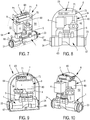
figure 5 est une vue en perspective d'un dispositif conforme à l'invention, - La
figure 6 est une autre vue en perspective du dispositif montré enfigure 5 , - La
figure 7 est une encore une autre vue en perspective du dispositif montré enfigure 5 , dont une paroi a été retirée et dont les parois restantes sont illustrées en transparence afin de montrer le contenu du dispositif,et 6 - La
figure 8 est une vue de face du dispositif montré enfigure 7 , - La
figure 9 est une autre vue en perspective du dispositif conforme à l'invention, les parois du dispositif étant représentées en transparence, la figure illustrant l'arrière du dispositif et les éléments qu'il comporte, - La
figure 10 est encore une autre vue en perspective du dispositif, les parois latérales du dispositif ayant été retirées (excepté la paroi arrière), - Et la
figure 11 montre un ensemble conforme à l'invention, comprenant un dispositif représenté en perspective et monté sur une canalisation, ainsi qu'un appareil représenté schématiquement, tenu dans une main d'un utilisateur.
- The
figure 1 is a perspective view of a solenoid valve according to the invention, - The
figure 2 is a side view of the solenoid valve shown infigure 1 , - The
figure 3 is a top view of the solenoid valve shown inFigures 1 and 2 , - The
figure 4 is a partial sectional view of the solenoid valve shown in the preceding figures, - The
figure 5 is a perspective view of a device according to the invention, - The
figure 6 is another perspective view of the device shown infigure 5 , - The
figure 7 is another yet another perspective view of the device shown infigure 5 and 6 , one wall of which has been removed and the remaining walls of which are illustrated in transparency in order to show the contents of the device, - The
figure 8 is a front view of the device shown infigure 7 , - The
figure 9 is another perspective view of the device according to the invention, the walls of the device being shown in transparency, the figure illustrating the rear of the device and the elements that it comprises, - The
figure 10 is yet another perspective view of the device, the side walls of the device having been removed (except the rear wall), - And the
figure 11 shows an assembly according to the invention, comprising a device shown in perspective and mounted on a pipe, and a device shown schematically, held in a hand of a user.
Dans la description qui suit, les termes « inférieur », « supérieur », « haut », « bas » etc... sont utilisés en référence aux dessins pour une plus grande facilité de compréhension. Ils ne doivent pas être compris comme étant des limitations de la portée de l'invention, notamment quant à l'orientation des éléments compris dans le dispositif, par exemple.In the following description, the terms "lower", "higher", "high", "low", etc. are used with reference to the drawings for greater ease of understanding. They should not be understood as being limitations of the scope of the invention, particularly as to the orientation of the elements included in the device, for example.
Dans un premier temps, il sera fait référence aux
L'électrovanne décrite est illustrée est une électrovanne à commande différentielle ou à membrane assistée : l'électrovanne à membrane assistée fonctionne grâce une bobine de commande qui assure l'ouverture ou la fermeture de l'électrovanne par transmission de signaux.The solenoid valve described is illustrated is a differential control or assisted diaphragm solenoid valve: the assisted diaphragm solenoid valve operates through a control coil which ensures the opening or closing of the solenoid valve by signal transmission.
L'électrovanne 1 montrée sur les figures comporte, comme il est en soit classique, un corps d'électrovanne 2 réalisé dans un matériau capable de supporter de fortes pressions internes.The
Le corps 2 comporte une partie inférieure 20 sensiblement longitudinale et creuse, ouverte à ses deux extrémités 21 et 22. L'ouverture de l'extrémité 21 constitue une entrée 23 de l'électrovanne 1, à raccorder à un tuyau d'arrivée d'eau, par exemple (eau ou tout autre fluide) et l'ouverture de l'extrémité 22 constitue une sortie 24 de l'électrovanne 1, à raccorder également au tuyau. Autrement dit, l'électrovanne se monte sur un tuyau d'arrivée d'eau (dans notre exemple) en raccordant son entrée 23 et sa sortie 24 au tuyau de sorte que l'eau sous pression dans le tuyau entre dans l'électrovanne par l'entrée 23 et sorte de l'électrovanne par la sortie 24.The
Un passage 25 est ainsi ménagé entre l'entrée 23 et la sortie 24 de la partie 1 de l'électrovanne et forme ce qui sera appelé par la suite un circuit primaire de passage de fluide (voir
Comme on peut la partie inférieur 20 creuse comporte une paroi interne transversale 26 qui se dresse sensiblement à mi-distance entre l'entrée 23 et la sortie 24, formant un obstacle à l'intérieur du passage 25.As may be the hollow lower portion has a transverse
Cet obstacle constitue une paroi déflectrice qui oriente le fluide entrant dans le passage 25 de l'électrovanne 1 vers une chambre interne 27 ménagée dans une seconde partie (ou partie supérieure) 28 de corps 2 (voir
L'électrovanne 1 comporte ainsi un second passage 29 permettant l'entrée de fluide dans la chambre 27. Elle comporte également un troisième passage 30 qui autorise la sortie du fluide de la chambre vers le passage 25 en aval de la paroi 26, en direction de la sortie 24 de l'électrovanne 1.The
Le passage 30 peut être fermé ou ouvert, de sorte à interdire ou autoriser la circulation de fluide entre l'entrée 23 et la2 sortie 24 de l'électrovanne. Pour ce faire, la chambre 27 comporte des moyens 3 de fermeture étanche qui sont mobiles entre une première position, dite ouverte, suivant laquelle le fluide est autorisé à circuler et à rejoindre le passage 25, et entre une seconde position, dite fermée, suivant laquelle le passage 30 est obstrué, obstruant également le passage 25 de sorte que toute circulation de fluide est impossible entre l'entrée 23 et la sortie 24 de l'électrovanne 1 (voir
Les moyens 3 de fermeture étanche sont réalisés par un clapet 31 qui comporte une membrane périphérique 32, souple, fixée entre la partie inférieure 20 et la partie supérieure 28 du corps de l'électrovanne. Le clapet 31 est monté mobile entre une position de fermeture (montrée en
Le clapet 31 est contraint en position de fermeture notamment par un système de bobine.The
Quand le clapet est en position de fermeture, on dit que l'électrovanne est fermée, et quand le clapet est en position d'ouverture, on dit que l'électrovanne est ouverte.When the valve is in the closed position, it is said that the solenoid valve is closed, and when the valve is in the open position, it is said that the solenoid valve is open.
Pour permettre le passage du clapet 31 de sa position fermée à sa position ouverte, l'électrovanne comporte un dispositif de commande 4, comme il est en soit connu.To allow the passage of the
Le dispositif de commande 4 est alimenté électriquement pour fonctionner. Le détail de fonctionnement de ce type de dispositif de commande ne sera pas décrit ici, étant connu de l'homme du métier et non nécessaire à la compréhension de l'invention.The
Conformément à l'invention, l'électrovanne 1 comporte un débitmètre 5 (ou détecteur de débit 5).According to the invention, the
Le débitmètre 5 et le dispositif de commande sont tous deux associés à la partie supérieure 28 du corps 2 de l'électrovanne. Le débitmètre 5 est incorporé dans la partie supérieure 28 du corps 2.The
La
L'entrée de chambre 51 et la sortie de chambre 52 débouchent toutes les deux dans le circuit primaire de passage du fluide, c'est-à-dire dans le passage 25. On peut ainsi considérer que le circuit emprunté par le fluide pénétrant dans la chambre 50 et sortant de la chambre est un circuit secondaire de passage de fluide. Ce circuit secondaire de passage de fluide permet d'isoler une partie du flux traversant l'électrovanne : c'est grâce à cet isolement que l'on peut détecter des micro-fuites dans la canalisation.The
La chambre 50 du débitmètre 5 comporte une turbine 53, montée libre en rotation autour de son axe, et comportant six ailettes 54.The
La chambre 50 comporte également une cellule de détection 55, placée au voisinage des ailettes 54 de la turbine, qui permet de détecter le passage d'une ailette devant elle. Ainsi, quand la turbine 53 réalise un tour complet, la cellule de détection compte six passages d'ailettes.The
Chaque passage d'ailette devant la cellule 55 est alors transformé en impulsion électrique qui peut alors être transmise sous forme de signal à un module /dispositif d'analyse extérieur, par exemple, au moyen d'un câble 56.Each fin passage in front of the
Le débitmètre 5 est ainsi capable d'acquérir des données concernant le débit du fluide traversant l'électrovanne 1, et en particulier le débit du flux secondaire extrait du flux primaire, et capable de transmettre ces données acquises à partir du flux secondaire à un module extérieur à l'électrovanne.The
On comprend de ce qui précède comment l'électrovanne conforme à l'invention permet, à la fois, de commander l'alimentation en fluide d'une installation, en fermant ou en ouvrant l'électrovanne 1 grâce au dispositif de commande 4 des moyens de fermetures 30 du circuit primaire de passage 25 du fluide.It will be understood from the foregoing how the solenoid valve according to the invention makes it possible both to control the supply of fluid to an installation, by closing or opening the
On comprend également comment l'invention permet de surveiller l'alimentation en fluide d'une installation grâce au débitmètre intégré 5 et au circuit secondaire de passage du fluide.It is also understood how the invention makes it possible to monitor the fluid supply of an installation by virtue of the
Ainsi réalisée, l'électrovanne 1 constitue un dispositif compact qui s'intègre dans une installation de plomberie aussi facilement qu'une électrovanne classique, sans être plus encombrante qu'une électrovanne classique.Thus achieved, the
On va maintenant s'intéresser à un dispositif conforme à l'invention qui intègre une telle électrovanne et qui permet d'offrir à un utilisateur des services, notamment pour avertir l'utilisateur d'une fuite, pour commander à distance ou automatiquement la fermeture ou l'ouverture de l'électrovanne.We will now be interested in a device according to the invention which incorporates such a solenoid valve and which provides a service to a user, in particular to warn the user of a leak, to remotely control or automatically closing or the opening of the solenoid valve.
Le dispositif conforme à l'invention porte la référence 6 sur les figures.The device according to the invention has
Il a pour fonction de permettre à un utilisateur distant d'être informé de l'état de son réseau et/ou de le piloter à distance en déclenchant divers scénarios. Le dispositif 6 est programmable selon le planning de l'utilisateur, ou activable de manière ponctuelle via un smartphone, une tablette, un ordinateur etc.Its function is to allow a remote user to be informed of the state of his network and / or to remotely control it by triggering various scenarios. The
L'utilisateur peut être un particulier, un hôtelier, une collectivité etc. et le dispositif peut être monté sur une canalisation de n'importe quel réseau et pour tout type de fluide.The user can be an individual, a hotelier, a community, etc. and the device can be mounted on a pipe of any network and for any type of fluid.
Le dispositif 6 est activable quand l'utilisateur le souhaite, ou en réponse à un signal ou quand un programme intrinsèque se déclenche. Le dispositif communique avec l'appareil de l'utilisateur via CPL, Bluetooth, ondes radio, wifi ou tout autre moyen de transmission d'informations connu.The
Le premier dispositif 6 qui est présenté comme exemple comporte un boitier 60 qui renferme tous les éléments propres au dispositif conforme à l'invention et qui se raccorde directement sur une canalisation. Ainsi réalisé, le boitier est facile à manipuler et à monter, puisqu'il se raccorde de façon classique en soit.The
Le boitier 60 comporte deux parois sensiblement parallèles latérales (paroi avant 61 et paroi arrière 62), une paroi de fond 63, et une paroi de bord 64, reliant les deux tranches libres 65 et 66 des deux parois latérales avant 61 et arrière 62. La paroi de bord 64 épouse une forme courbe qui est définie par la forme courbe des tranches libres 65 et 66 des parois latérales 61 et 62.The housing 60 has two substantially parallel lateral walls (
Le boitier 60 comporte, conformément à l'invention, une entrée 67 réalisée par une ouverture traversante à travers la paroi de bord 64, au voisinage de la paroi de fond 63. Le boitier 60 comporte également une sortie 68 réalisée également par une ouverture traversante à travers la paroi de bord 64, à l'opposé de l'ouverture réalisant l'entrée 67 et au voisinage de la paroi de fond 63.The housing 60 comprises, according to the invention, an
L'entrée 67 du boitier 60 est conçue pour accueillir l'entrée 23 de l'électrovanne et la sortie 68 du boitier 60 est conçue pour accueillir la sortie 24 de l'électrovanne. L'entrée 67 et la sortie 68 livrent donc passage (donnent accès) aux entrée 23 et sortie 24 de l'électrovanne.The
Le boitier comporte donc l'électrovanne décrite ci avant et montrée en
Le dispositif de commande 4 et le débitmètre 5 sont tous deux alimentés en énergie (indirectement) par une source d'énergie 7 que comporte le dispositif de surveillance 6.The
Dans le cadre de ce mode de réalisation, la source d'énergie 7 est réalisée par deux piles 71 reçues dans un logement 70 ménagé dans le boitier du dispositif. Le logement 70 comporte des bornes de raccordement des piles 71 et l'ensemble constitue un dispositif d'alimentation en énergie du dispositif de surveillance conforme à l'invention.In the context of this embodiment, the
L'accès au logement 70, pour insérer des piles ou retirer les piles 71, se fait par une trappe d'ouverture 69 qui est réalisée par découpe d'une partie de paroi de bord 64 en région supérieure du boitier 60. La
La trappe 69 est montée pivotante autour de l'une de ses côtés par une charnière qui la relie à la paroi de bord 64.The
Conformément à l'invention, le dispositif d'alimentation en énergie (70, 71) alimente un module 8 de réception et de traitement de données auquel sont reliés le débitmètre 5 et le dispositif de commande 4 (le module 8 est visible sur les
Le module 8 peut être réalisé concrètement de différentes manières : dans le cadre de ce mode de réalisation, il comporte une carte électronique 80 qui permet de recevoir des données, les analyser, générer de nouvelles données et les transmettre, à destination d'un appareil utilisateur 9 extérieur au dispositif 6, sous forme de signaux d'informations 90 via des réseaux de diffusion variés tels que le Wifi, le Bluetooth, ondes radios diverses etc.The
La carte électronique 80 peut également recevoir des signaux d'informations 91 provenant de l'extérieur du boitier 60, les analyser et commander une action de l'électrovanne en réponse aux signaux 91, en transmettant des ordres au dispositif de commande 4 des moyens de fermeture de l'électrovanne.The
Il va maintenant être fait référence à la
Dans le cadre de cet exemple, le dispositif 6 est monté sur une canalisation 10 d'arrivée d'eau du domicile d'un utilisateur (illustré schématiquement par la main 11 sur la
L'appareil d'utilisateur 9 est apte à mettre en oeuvre une application informatique, dédiée au fonctionnement du dispositif 6.The
L'appareil utilisateur est par exemple un smartphone, comme illustré en
Une fuite d'eau est repérée par le dispositif de surveillance 6 suite au traitement des données d'impulsions transmises par le débitmètre 5 au module 8.A leak of water is identified by the
Le module 8 envoie alors un signal 90 à l'appareil d'utilisateur 9 qui informe alors l'utilisateur de la présence d'une fuite dans le réseau d'alimentation de son domicile.The
L'appareil d'utilisateur 9 indique également à l'utilisateur que le circuit d'alimentation en eau de son domicile a été coupé : en effet, dans le scénario présent, la détection de la fuite d'eau par le module 8 a déclenché la fermeture de l'électrovanne 1 car le module 8, en plus de la transmission du signal 90, à transmis au dispositif de commande 4 un ordre de fonctionnement : celui de fermer le clapet 31.The
L'utilisateur est alors invité, via l'application de son smartphone 9, à contacter un plombier.The user is then invited, via the application of his
Le module 8 peut également avoir envoyé un signal à un autre appareil dont serait équipé un plombier, pour commander une intervention du plombier.The
On comprend de ce qui précède comment l'invention permet de surveiller l'état de fonctionnement d'un système d'alimentation en fluide d'une installation, que ce soit une installation de plomberie domestique ou une autre installation qui comprendrait une canalisation à travers laquelle transite un fluide alimentant l'installation.It is understood from the foregoing how the invention makes it possible to monitor the operating state of a fluid supply system of an installation, be it a domestic plumbing installation or another installation which would include a pipe through which passes a fluid supplying the installation.
Il devra toutefois être compris que l'invention n'est pas limitée au mode de réalisation spécifiquement représenté sur les figures et qu'elle s'étend à la mise en oeuvre de tout moyen équivalent.However, it should be understood that the invention is not limited to the embodiment specifically shown in the figures and that it extends to the implementation of any equivalent means.
Par exemple, dans le dispositif de surveillance et de commande 6 pourrait présenter une autre forme et le module 8 pourrait être réalisé différemment : il pourrait comprendre d'autres moyens techniques que ceux décrits, réalisant les mêmes fonctions techniques, sans sortir du cadre de l'invention.For example, in the monitoring and
Egalement, dans le cadre de l'ensemble conforme à l'invention, l'appareil d'utilisateur 11 pourrait être différent: il pourrait s'agir d'un boitier dédié au fonctionnement du dispositif de surveillance et capable de communiquer avec ce dernier via CPL, Bluetooth, ondes radio etc.Also, as part of the assembly according to the invention, the
L'appareil serait programmé pour mettre en oeuvre plusieurs scénarios en fonction des informations qui lui seraient transmises par le dispositif de surveillance 6. Par exemple, il pourrait être envisagé que l'appareil d'utilisateur puisse commander la gestion des flux de fluide d'une installation, commander un mode de fonctionnement de l'électrovanne suivant certaines plages horaires (dans le cadre d'un arrosage automatique de jardin, par exemple) enregistrer des données dans un historique, indiquer à l'utilisateur sa consommation en eau...The apparatus would be programmed to implement several scenarios according to the information that would be transmitted to it by the
Le dispositif 6 de surveillance pourrait également être équipé d'une alarme sonore ou bien il pourrait transmettre des informations à l'appareil sur le niveau de consommation des piles 71.The
Le dispositif conforme à l'invention trouve un intérêt particulier pour les professionnels de la plomberie, les distributeurs de domotique, les particuliers et les professionnels dont l'activité nécessite la mise en oeuvre d'une installation dans laquelle circule un fluide (jardiniers, agriculteurs, collectivités, par exemple).The device according to the invention is of particular interest to plumbing professionals, home automation distributors, individuals and professionals whose activity requires the implementation of a facility in which circulates a fluid (gardeners, farmers communities, for example).
Claims (10)
Caractérisée en ce que le débitmètre (5) comporte une chambre (50) ménagée dans le corps (2) de l'électrovanne (1), ladite chambre (50) comportant en outre une entrée de chambre (51) et une sortie de chambre (52) qui sont reliées audit circuit primaire de passage du fluide dans l'électrovanne (1), un circuit secondaire de passage de fluide étant défini entre ladite entrée de chambre (51) et ladite sortie de chambre (52).Solenoid valve (1) for monitoring and controlling the fluid supply of a building installation, said installation comprising a pipe (10) in which a fluid circulates, said solenoid valve comprising:
Characterized in that the flowmeter (5) has a chamber (50) in the body (2) of the solenoid valve (1), said chamber (50) further comprising a chamber inlet (51) and a chamber outlet (51). (52) which are connected to said primary fluid passage circuit in the solenoid valve (1), a secondary fluid passage circuit being defined between said chamber inlet (51) and said chamber outlet (52).
Applications Claiming Priority (1)
| Application Number | Priority Date | Filing Date | Title |
|---|---|---|---|
| FR1770277A FR3064332A1 (en) | 2017-03-21 | 2017-03-21 | SOLENOID VALVE FOR MONITORING AND CONTROLLING THE FLUID SUPPLY OF AN INSTALLATION OF A BUILDING, AND DEVICE COMPRISING ALSO SUCH A SOLENOID VALVE |
Publications (1)
| Publication Number | Publication Date |
|---|---|
| EP3379121A1 true EP3379121A1 (en) | 2018-09-26 |
Family
ID=59253817
Family Applications (1)
| Application Number | Title | Priority Date | Filing Date |
|---|---|---|---|
| EP18162236.6A Withdrawn EP3379121A1 (en) | 2017-03-21 | 2018-03-16 | Solenoid valve for monitoring and controlling the fluid supply to a building installation, and device further comprising such a solenoid valve |
Country Status (4)
| Country | Link |
|---|---|
| US (1) | US20180274212A1 (en) |
| EP (1) | EP3379121A1 (en) |
| CA (1) | CA2998373A1 (en) |
| FR (1) | FR3064332A1 (en) |
Families Citing this family (5)
| Publication number | Priority date | Publication date | Assignee | Title |
|---|---|---|---|---|
| IT201700112681A1 (en) * | 2017-10-06 | 2019-04-06 | Eltek Spa | HYDRAULIC CONTROL DEVICE FOR LIQUID CONDUCTOR EQUIPMENT AND SYSTEMS |
| GB2574881B (en) * | 2018-06-22 | 2021-07-07 | Creative Ec Ltd | Control valve |
| GB201820133D0 (en) * | 2018-12-11 | 2019-01-23 | Secr Defence | Pipe clamp, pinch valve, and method of use |
| CN110144995A (en) * | 2019-06-04 | 2019-08-20 | 四川厚森工程技术服务有限公司 | Mobile phone controls cloud remote automatic-taking-water system |
| WO2022241231A1 (en) | 2021-05-14 | 2022-11-17 | Rain Bird Corporation | Self-powered irrigation systems, generator systems and methods of controlling irrigation |
Citations (7)
| Publication number | Priority date | Publication date | Assignee | Title |
|---|---|---|---|---|
| EP1101986A1 (en) * | 1998-08-05 | 2001-05-23 | Zhaokeng Pan | Electric-control valve for regulating flow of fluid |
| US6701956B1 (en) * | 1998-12-13 | 2004-03-09 | Bermad | Water control device |
| US20090194719A1 (en) * | 2008-02-05 | 2009-08-06 | Timothy David Mulligan | Fluid supply monitoring system |
| WO2013006707A1 (en) * | 2011-07-05 | 2013-01-10 | Rain Bird Corporation | Diaphragm valve and methods and accessories therefor |
| WO2014178920A2 (en) * | 2013-04-30 | 2014-11-06 | Flood Monkey Inc. | Intelligent electronic water flow regulation system |
| US20160356026A1 (en) * | 2015-06-03 | 2016-12-08 | Robertshaw Controls Company | Rf-signal-emitting valve for flow monitoring and leak detection |
| WO2017219142A1 (en) * | 2016-06-22 | 2017-12-28 | Homebeaver Inc. | Fluid flow measuring and control devices and method |
Family Cites Families (7)
| Publication number | Priority date | Publication date | Assignee | Title |
|---|---|---|---|---|
| JPS6449927A (en) * | 1987-08-20 | 1989-02-27 | Matsushita Electric Ind Co Ltd | Water leak detecting device |
| IT1249897B (en) * | 1991-06-06 | 1995-03-30 | Eltek Spa | "INTEGRATED DEVICE FOR VOLUMETRIC CONTROL OF FLUIDS FLUID THROUGH SOLENOID VALVES, FOR MACHINES FOR DISTRIBUTING LIQUIDS AND WASHING MACHINES. |
| GB9404456D0 (en) * | 1994-03-08 | 1994-04-20 | Wheaton Roger B | Flow measuring and detecting systems |
| CA2776512C (en) * | 2003-11-18 | 2014-07-22 | Kimura Corporation | Flow control device |
| FR2870321B1 (en) * | 2004-05-14 | 2006-08-04 | Hydrelys Soc Par Actions Simpl | CIRCUIT BREAKER FOR LIQUID OR GASEOUS FLUID PIPING |
| US20100212748A1 (en) * | 2009-02-20 | 2010-08-26 | John Andrew Davidoff | System and method for detecting and preventing fluid leaks |
| US8833390B2 (en) * | 2011-05-31 | 2014-09-16 | Mueller International, Llc | Valve meter assembly and method |
-
2017
- 2017-03-21 FR FR1770277A patent/FR3064332A1/en active Pending
-
2018
- 2018-03-16 CA CA2998373A patent/CA2998373A1/en not_active Abandoned
- 2018-03-16 EP EP18162236.6A patent/EP3379121A1/en not_active Withdrawn
- 2018-03-20 US US15/926,438 patent/US20180274212A1/en not_active Abandoned
Patent Citations (7)
| Publication number | Priority date | Publication date | Assignee | Title |
|---|---|---|---|---|
| EP1101986A1 (en) * | 1998-08-05 | 2001-05-23 | Zhaokeng Pan | Electric-control valve for regulating flow of fluid |
| US6701956B1 (en) * | 1998-12-13 | 2004-03-09 | Bermad | Water control device |
| US20090194719A1 (en) * | 2008-02-05 | 2009-08-06 | Timothy David Mulligan | Fluid supply monitoring system |
| WO2013006707A1 (en) * | 2011-07-05 | 2013-01-10 | Rain Bird Corporation | Diaphragm valve and methods and accessories therefor |
| WO2014178920A2 (en) * | 2013-04-30 | 2014-11-06 | Flood Monkey Inc. | Intelligent electronic water flow regulation system |
| US20160356026A1 (en) * | 2015-06-03 | 2016-12-08 | Robertshaw Controls Company | Rf-signal-emitting valve for flow monitoring and leak detection |
| WO2017219142A1 (en) * | 2016-06-22 | 2017-12-28 | Homebeaver Inc. | Fluid flow measuring and control devices and method |
Also Published As
| Publication number | Publication date |
|---|---|
| US20180274212A1 (en) | 2018-09-27 |
| CA2998373A1 (en) | 2018-09-21 |
| FR3064332A1 (en) | 2018-09-28 |
Similar Documents
| Publication | Publication Date | Title |
|---|---|---|
| EP3379121A1 (en) | Solenoid valve for monitoring and controlling the fluid supply to a building installation, and device further comprising such a solenoid valve | |
| FR2985802A1 (en) | MODULAR ELEMENT FOR GAS DISTRIBUTION UNDER PRESSURE AND CORRESPONDING INSTALLATION | |
| JP2010507094A (en) | Fluid monitoring apparatus and operation method thereof | |
| FR2757926A1 (en) | CHANNEL CONTROL DEVICE FOR CONNECTING WITH A BOREHOLE SYSTEM | |
| WO2018115713A1 (en) | Compact multi-way valve for connecting two fluid-circulation circuits | |
| EP3248385A1 (en) | Scalable system and methods for monitoring and controlling a sanitary facility using distributed connected devices | |
| EP3012499B1 (en) | System for monitoring water dispensing and associated water dispensing device | |
| FR2647209A1 (en) | REMOTE READING AND CUTTING SYSTEM OF DOMESTIC GAS METERS | |
| EP2350601A2 (en) | Method for assessing the seal of a servomotor housing | |
| FR2748811A1 (en) | GAS SURFACE FLOW MEASUREMENT | |
| EP3388585B1 (en) | Hydraulic system for managing the water supply to a member | |
| FR3068996B1 (en) | MODULAR CONTROL SYSTEM OF A DISTRIBUTION NETWORK | |
| EP3945168B1 (en) | Device for connecting sanitary equipment with a pipe | |
| FR3141982A1 (en) | Fluid connection device | |
| WO2021185803A1 (en) | Assembly comprising a valve and at least one connector | |
| FR3074928A1 (en) | ELECTRONIC CONTROL APPARATUS FOR CONTROLLING A BASE VALVE | |
| FR3129531A1 (en) | SET FOR ONE VEHICLE WITH MULTIPLE BATTERIES AND EVACUATION SYSTEM | |
| EP3089131B1 (en) | Method and system for remote protection | |
| EP0881424B1 (en) | Condensate removal device for air or gas treatment plants | |
| CH714466A2 (en) | Device for monitoring and management of a technical installation, method implemented by this device and associated system. | |
| FR3017455A1 (en) | FLUID COUNTER DEVICE HAVING LEAK DETECTION MEANS | |
| FR3066595A1 (en) | WATER MANAGEMENT AND SAVING DEVICE | |
| FR2844731A1 (en) | Washing case for milk cooler tank emptying nose comprises hollow body fixed to emptying pipe and cover which seals pipe end, and pair of outlet pipes able to be positioned for right or left connections | |
| EP4170310A1 (en) | Pressure measurement device and system | |
| WO2014140343A1 (en) | Monitoring device for the tending of plants and corresponding system |
Legal Events
| Date | Code | Title | Description |
|---|---|---|---|
| PUAI | Public reference made under article 153(3) epc to a published international application that has entered the european phase |
Free format text: ORIGINAL CODE: 0009012 |
|
| AK | Designated contracting states |
Kind code of ref document: A1 Designated state(s): AL AT BE BG CH CY CZ DE DK EE ES FI FR GB GR HR HU IE IS IT LI LT LU LV MC MK MT NL NO PL PT RO RS SE SI SK SM TR |
|
| AX | Request for extension of the european patent |
Extension state: BA ME |
|
| STAA | Information on the status of an ep patent application or granted ep patent |
Free format text: STATUS: THE APPLICATION IS DEEMED TO BE WITHDRAWN |
|
| 18D | Application deemed to be withdrawn |
Effective date: 20190327 |