EP3347259B1 - A trailer - Google Patents
A trailer Download PDFInfo
- Publication number
- EP3347259B1 EP3347259B1 EP16794386.9A EP16794386A EP3347259B1 EP 3347259 B1 EP3347259 B1 EP 3347259B1 EP 16794386 A EP16794386 A EP 16794386A EP 3347259 B1 EP3347259 B1 EP 3347259B1
- Authority
- EP
- European Patent Office
- Prior art keywords
- trailer
- tubular
- sections
- connection
- shaped
- Prior art date
- Legal status (The legal status is an assumption and is not a legal conclusion. Google has not performed a legal analysis and makes no representation as to the accuracy of the status listed.)
- Active
Links
- 239000000725 suspension Substances 0.000 claims description 16
- 125000006850 spacer group Chemical group 0.000 claims description 4
- 230000001012 protector Effects 0.000 description 2
- 230000000712 assembly Effects 0.000 description 1
- 238000000429 assembly Methods 0.000 description 1
- 230000000295 complement effect Effects 0.000 description 1
- 238000010276 construction Methods 0.000 description 1
- 230000008878 coupling Effects 0.000 description 1
- 238000010168 coupling process Methods 0.000 description 1
- 238000005859 coupling reaction Methods 0.000 description 1
- 238000005303 weighing Methods 0.000 description 1
Images


Classifications
-
- B—PERFORMING OPERATIONS; TRANSPORTING
- B62—LAND VEHICLES FOR TRAVELLING OTHERWISE THAN ON RAILS
- B62D—MOTOR VEHICLES; TRAILERS
- B62D63/00—Motor vehicles or trailers not otherwise provided for
- B62D63/06—Trailers
- B62D63/061—Foldable, extensible or yielding trailers
-
- B—PERFORMING OPERATIONS; TRANSPORTING
- B62—LAND VEHICLES FOR TRAVELLING OTHERWISE THAN ON RAILS
- B62D—MOTOR VEHICLES; TRAILERS
- B62D21/00—Understructures, i.e. chassis frame on which a vehicle body may be mounted
- B62D21/12—Understructures, i.e. chassis frame on which a vehicle body may be mounted assembled from readily detachable parts
-
- B—PERFORMING OPERATIONS; TRANSPORTING
- B62—LAND VEHICLES FOR TRAVELLING OTHERWISE THAN ON RAILS
- B62D—MOTOR VEHICLES; TRAILERS
- B62D21/00—Understructures, i.e. chassis frame on which a vehicle body may be mounted
- B62D21/14—Understructures, i.e. chassis frame on which a vehicle body may be mounted of adjustable length or width
-
- B—PERFORMING OPERATIONS; TRANSPORTING
- B62—LAND VEHICLES FOR TRAVELLING OTHERWISE THAN ON RAILS
- B62D—MOTOR VEHICLES; TRAILERS
- B62D21/00—Understructures, i.e. chassis frame on which a vehicle body may be mounted
- B62D21/18—Understructures, i.e. chassis frame on which a vehicle body may be mounted characterised by the vehicle type and not provided for in groups B62D21/02 - B62D21/17
- B62D21/20—Understructures, i.e. chassis frame on which a vehicle body may be mounted characterised by the vehicle type and not provided for in groups B62D21/02 - B62D21/17 trailer type, i.e. a frame specifically constructed for use in a non-powered vehicle
-
- B—PERFORMING OPERATIONS; TRANSPORTING
- B62—LAND VEHICLES FOR TRAVELLING OTHERWISE THAN ON RAILS
- B62D—MOTOR VEHICLES; TRAILERS
- B62D53/00—Tractor-trailer combinations; Road trains
- B62D53/04—Tractor-trailer combinations; Road trains comprising a vehicle carrying an essential part of the other vehicle's load by having supporting means for the front or rear part of the other vehicle
- B62D53/06—Semi-trailers
- B62D53/067—Multi-purpose, convertible or extendable load surface semi-trailers
Definitions
- the invention relates to a trailer, particularly a modular trailer that can be readily assembled and disassembled and is easy to transport.
- Trailers are useful for transporting various items and goods; however, when they are not being used, they take up a considerable amount of space, which can make them difficult to store. Furthermore, trailers are generally of a set size and so different trailers must be used for different loads. As a result, one may require several trailers, all of which need storing when not in use.
- FR2735733 (Bernard ) discloses a carrier with two hinged arms at the rear to support a number plate and rear lights when the arms are in their unfolded position.
- the hinge is on the central axis of the carrier attached to a bar (4) that runs along the central axis and the hinged arms fold along the bar (4) for storage.
- US2009026736 discloses a sport trailer having a centre load supporting rail, wheels, and a stowable telescopic towing tongue.
- the towing tongue is removably received within an inner channel of the centre rail and telescopes to achieve different length configurations of the trailer.
- WO2015158944 (Little Way Team ) discloses a modular trailer with a foldable configuration.
- the trailer has a main frame module with a trailer coupler bar assembly set, two mountings having wheels having retractable wheels and a self-supporting frame (9) intended for being coupled with other complementary modules.
- the present invention is directed to a modular trailer comprising:
- the user of such a trailer allows for it to be stored easily and for its size to be increased by attaching further elements, thereby enabling a user to have a single trailer for transporting loads of varying size.
- connection section of each element of the trailer comprises a flange with apertures therein and the elements of the trailer are connected by way of retaining bolts with locking nuts passing through the apertures of the respective flanges.
- a spacer with a flange is arranged between the connection section and each element is connected thereto.
- the wheels are provided with hydraulic brakes and/or the wheels are provided with suspension. Providing brakes and suspension to the trailer protects the load and makes towing the trailer safer.
- the width of the modular trailer may be extended by attaching further tubular sections to the tubular sections connected to the tubular central chassis spine. Allowing the width and the length to be controlled by attaching and removing tubular parts enables the size and strength of the trailer to be adapted. This allows a single central chassis spine to be employed in a plurality of different trailer arrangements, thereby making the trailer flexible.
- the invention extends to a kit comprising:
- the trailer By being in kit form the trailer is readily assembled and disassembled and can be stored with a smaller footprint than the assembled trailer.
- connection sections comprise a flange with apertures therein.
- Each tubular part, or at least some of them, may comprise a flange at each end so as to enable it to be connected to an adjacent part by aligning the flanges and providing connecting means, most likely in the form of bolts, to join them.
- FIGS. 1 and 2 show a trailer 10 comprising a tubular central chassis spine 12 that is made up from three central cross-shaped sections 14 connected in longitudinally, along with extending tubes 16 connecting the cross-shaped sections 14 to T-shaped end sections 18 and 20, which form the respective ends of the trailer 10.
- the trailer 10 is provided with transverse extension tubes 28 at the first T-shaped end section 18 to extend its width and the ends of those extension tubes 28 are provided with end tubes 30, which are in turn provided with end protectors 32 at their 'free' end.
- the first T-shaped end section 18 forms the front end of the trailer 10 and is connected to a tow bar assembly 22.
- the second T-shaped end second 20 forms the rear end of the trailer 10 and is provided with a light units 24 at each end of the respective transverse ends for holding lights.
- a number-plate receiving section 26 for receiving and holding a number-plate is attached to the rear.
- transverse tubular structures there are five transverse tubular structures, those being the front end (including first T-shaped end section 18), a first wheel-connecting spar section (including the first of the three cross-shaped section 14), a second wheel-connecting spar (including the second of the three cross-shaped section 14), a support spar (including the third of the three cross-shaped section 14) and the rear T-shaped end section 20.
- Each of the wheel-connecting spars 34 are provided with suspension modules 36 at their free ends, to which are connected wheels 38.
- the rotational orientation of the suspension modules 36 may be adjusted according to the requirements of the trailer 10, as shown in Figures 7 and 8 .
- top connector bracket 40 is supplied at each junction between two tubular parts.
- the top connector bracket 40 may be used to connect a bed (not shown) to the chassis of the trailer 10.
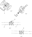
- An exploded view of the connector 40 is shown in Figures 5 and 6 , which also detail how it may be connected on an angle, if desired.
- the tow bar assembly 22 may comprise an "A" draw-bar or an "I" draw-bar to connect the front end of the trailer 10. Additionally, the tow bar assembly 22 is provided with adjustment means 42 to change the angle and height of the tow bar connection. An exploded view of the adjustment mechanism is shown in Figure 4 .
- FIG 13 shows a further trailer 10a according to the present invention that comprises two end sections 18a and 20a with a support spar therebetween.
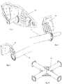
- an underslung suspension system may be desirable, thus, underslung suspension supports 44 are provided, each having one end connected to a transverse spar or end of the trailer and the other ends connecting to form a V-shape to which a suspension module may be connected, as shown in Figures 14 and 15 .
- Figure 16 shows an enlarged trailer 10b, which comprises further cross-shaped sections 14b.
- Figure 17 shows a further embodiment 10c, wherein the connector brackets are connected to ribs 46 that provide structural rigidity and strength to the trailer 10c.
- the ribs may be single sections that run the length of the trailer 10c, or, more preferably, they are shorter, individual units that reach (and connect) the spars and end sections.
- the tubular trailer system can be constructed using separate standard parts. These parts are able to be taken apart, re-positioned in many combinations so that the user has varying sizes of trailer height, length and width depending on the requirement use.
- plates separate each tubular component so that other parts maybe be fixed to the chassis by way of bolting or fixing devices.
- the number of axles and their relationship to the centre line of the chassis spine, or backbone, can be changed so that the axles maybe inline or offset to the longitudinal axis.
- the main load carrying torsional frame spine from where the following may be mounted in varying formats and arrangements: outriggers; axles; drawbars; mounting plates; and extension tubes.
- the lateral axis can be extended by way of fixing standard tubular parts with the option to fix the wheel station either on the same axis or by way of parts below the axis of the lateral plane.
- the trailer may be readily disassembled and carried/transported with no component weighing more than 20kg or being longer than 1000mm.
- the coupling of the parts element may be undertaken by way of pre-drilled flanges that are the same dimension throughout.
- the flanges may be connected by way of retaining bolts with locking nuts.
- a connector bracket or spacer, which is designed to be multi-functional.
- the connector bracket allows for an external device, object or assembly maybe fixed to the trailer.
- the bracket can be mounted in a variety of orientations, or angles.
- the ability to off-set and rotate the wheel station suspension system means that an awkwardly-shaped superstructures or loads are able to be fitted to the trailer chassis and still allow for evenly uninterrupted weight distribution.
- the trailer may be used without a suspension module with the wheels simply attaching to the trailer.
Description
- The invention relates to a trailer, particularly a modular trailer that can be readily assembled and disassembled and is easy to transport.
- Trailers are useful for transporting various items and goods; however, when they are not being used, they take up a considerable amount of space, which can make them difficult to store. Furthermore, trailers are generally of a set size and so different trailers must be used for different loads. As a result, one may require several trailers, all of which need storing when not in use.
-
FR2735733 (Bernard -
US2009026736 (Koch ) discloses a sport trailer having a centre load supporting rail, wheels, and a stowable telescopic towing tongue. The towing tongue is removably received within an inner channel of the centre rail and telescopes to achieve different length configurations of the trailer. -
WO2015158944 (Little Way Team ) discloses a modular trailer with a foldable configuration. The trailer has a main frame module with a trailer coupler bar assembly set, two mountings having wheels having retractable wheels and a self-supporting frame (9) intended for being coupled with other complementary modules. - Accordingly, the present invention is directed to a modular trailer comprising:
- a tubular central chassis spine constructed from at least one cross-shaped tubular section, wherein two of the limbs of the cross-shaped tubular section extend axially and the other two limbs extend transversely, each of the limbs being provided with connection sections at their ends;
- a plurality of tubular sections connected to the connection sections of the transversely extending limbs of the at least one cross-shaped tubular structure, wherein at least two of the tubular sections are provided with wheels;
- a tubular T-shaped end section connected to the connection section of one of the axially extending limbs of the central chassis spine; and
- a towing connection connected to the connection section at the opposite end of the central chassis spine from that of the end T-shaped tubular section,
- The user of such a trailer allows for it to be stored easily and for its size to be increased by attaching further elements, thereby enabling a user to have a single trailer for transporting loads of varying size.
- Preferably, the connection section of each element of the trailer comprises a flange with apertures therein and the elements of the trailer are connected by way of retaining bolts with locking nuts passing through the apertures of the respective flanges. More preferably, a spacer with a flange is arranged between the connection section and each element is connected thereto.
- In one arrangement, the wheels are provided with hydraulic brakes and/or the wheels are provided with suspension. Providing brakes and suspension to the trailer protects the load and makes towing the trailer safer.
- The width of the modular trailer may be extended by attaching further tubular sections to the tubular sections connected to the tubular central chassis spine. Allowing the width and the length to be controlled by attaching and removing tubular parts enables the size and strength of the trailer to be adapted. This allows a single central chassis spine to be employed in a plurality of different trailer arrangements, thereby making the trailer flexible.
- The invention extends to a kit comprising:
- a plurality of cross-shaped tubular sections
- a plurality of tubular sections;
- a tubular T-shaped end section;
- a towing connection; and
- a plurality of wheels,
- By being in kit form the trailer is readily assembled and disassembled and can be stored with a smaller footprint than the assembled trailer.
- Preferably, the connection sections comprise a flange with apertures therein. Each tubular part, or at least some of them, may comprise a flange at each end so as to enable it to be connected to an adjacent part by aligning the flanges and providing connecting means, most likely in the form of bolts, to join them.
- An embodiment of the invention will now be described, by way of example only, and with reference to the accompanying drawings, in which:
-
Figure 1 is a drawing showing an embodiment of the present invention; -
Figure 2 is an enlarged view of a tow bar of the present invention; -
Figure 3 is an enlarged view of part of the tow bar ofFigure 2 ; -
Figure 4 is an exploded view of the part ofFigure 3 ; -
Figure 5 is a an exploded view of the framework of the trailer of theFigure 1 ; -
Figure 6 is a further view of the framework ofFigure 5 ; -
Figure 7 is a view of a suspension module for use with the trailer ofFigure 1 ; -
Figure 8 is a view of the suspension module ofFigure 7 attached to the trailer ofFigure 1 ; -
Figure 9 is a further view of the suspension module ofFigure 7 -
Figure 10 is a view of a cross-shaped tubular for use in the trailer ofFigure 1 ; -
Figure 11 is an end protector for use with the trailer ofFigure 1 ; -
Figure 12 is a light holder unit for use with the trailer ofFigure 1 ; -
Figure 13 is a view of the tubular structure of a trailer in accordance with the present invention; -
Figure 14 is a view of the tubular structure ofFigure 13 with underslung suspension connectors attached; -
Figure 15 is a view of the components for enabling underslung suspension; -
Figure 16 is a view of a further trailer in accordance with the present invention; and -
Figure 17 shows a further embodiment of a trailer in accordance with the present invention. - The Figures show a
trailer 10 comprising a tubularcentral chassis spine 12 that is made up from threecentral cross-shaped sections 14 connected in longitudinally, along with extendingtubes 16 connecting thecross-shaped sections 14 to T-shaped end sections trailer 10. - The
trailer 10 is provided withtransverse extension tubes 28 at the first T-shaped end section 18 to extend its width and the ends of thoseextension tubes 28 are provided withend tubes 30, which are in turn provided withend protectors 32 at their 'free' end. - The first T-
shaped end section 18 forms the front end of thetrailer 10 and is connected to atow bar assembly 22. The second T-shaped end second 20 forms the rear end of thetrailer 10 and is provided with alight units 24 at each end of the respective transverse ends for holding lights. A number-plate receiving section 26 for receiving and holding a number-plate is attached to the rear. - In the embodiment shown in
Figure 1 , there are five transverse tubular structures, those being the front end (including first T-shaped end section 18), a first wheel-connecting spar section (including the first of the three cross-shaped section 14), a second wheel-connecting spar (including the second of the three cross-shaped section 14), a support spar (including the third of the three cross-shaped section 14) and the rear T-shaped end section 20. - Each of the wheel-connecting
spars 34 are provided withsuspension modules 36 at their free ends, to which are connectedwheels 38. The rotational orientation of thesuspension modules 36 may be adjusted according to the requirements of thetrailer 10, as shown inFigures 7 and 8 . - At each junction between two tubular parts, a
top connector bracket 40 is supplied. Thetop connector bracket 40 may be used to connect a bed (not shown) to the chassis of thetrailer 10. An exploded view of theconnector 40 is shown inFigures 5 and 6 , which also detail how it may be connected on an angle, if desired. - The
tow bar assembly 22 may comprise an "A" draw-bar or an "I" draw-bar to connect the front end of thetrailer 10. Additionally, thetow bar assembly 22 is provided with adjustment means 42 to change the angle and height of the tow bar connection. An exploded view of the adjustment mechanism is shown inFigure 4 . -
Figure 13 shows afurther trailer 10a according to the present invention that comprises twoend sections 18a and 20a with a support spar therebetween. In such an arrangement, an underslung suspension system may be desirable, thus, underslung suspension supports 44 are provided, each having one end connected to a transverse spar or end of the trailer and the other ends connecting to form a V-shape to which a suspension module may be connected, as shown inFigures 14 and15 . -
Figure 16 shows anenlarged trailer 10b, which comprises furthercross-shaped sections 14b. -
Figure 17 shows afurther embodiment 10c, wherein the connector brackets are connected to ribs 46 that provide structural rigidity and strength to thetrailer 10c. The ribs may be single sections that run the length of thetrailer 10c, or, more preferably, they are shorter, individual units that reach (and connect) the spars and end sections. - Features of different trailers described and shown herein may be employed in other trailers described and shown herein. For example, the underslung suspension shown in
Figure 14 may be employed in the trailer ofFigure 17 . Likewise, different tow bar assemblies may be interchanged. - The tubular trailer system can be constructed using separate standard parts. These parts are able to be taken apart, re-positioned in many combinations so that the user has varying sizes of trailer height, length and width depending on the requirement use. Within the construction, plates separate each tubular component so that other parts maybe be fixed to the chassis by way of bolting or fixing devices. The number of axles and their relationship to the centre line of the chassis spine, or backbone, can be changed so that the axles maybe inline or offset to the longitudinal axis.
- Along the longitudinal and diagonal axes of the trailer is the main load carrying torsional frame spine from where the following may be mounted in varying formats and arrangements: outriggers; axles; drawbars; mounting plates; and extension tubes.
The lateral axis can be extended by way of fixing standard tubular parts with the option to fix the wheel station either on the same axis or by way of parts below the axis of the lateral plane. - The trailer may be readily disassembled and carried/transported with no component weighing more than 20kg or being longer than 1000mm.
- The coupling of the parts element may be undertaken by way of pre-drilled flanges that are the same dimension throughout. The flanges may be connected by way of retaining bolts with locking nuts. Between each assembly is a connector bracket, or spacer, which is designed to be multi-functional. The connector bracket allows for an external device, object or assembly maybe fixed to the trailer. The bracket can be mounted in a variety of orientations, or angles.
- The ability to off-set and rotate the wheel station suspension system means that an awkwardly-shaped superstructures or loads are able to be fitted to the trailer chassis and still allow for evenly uninterrupted weight distribution.
- The trailer may be used without a suspension module with the wheels simply attaching to the trailer.
wherein the length of the modular trailer spine is extendible by attaching further cross-shaped tubular sections to the connection sections of the axial limbs of the tubular central chassis spine.
Claims (10)
- A modular trailer (10) comprising:a tubular central chassis spine (12) constructed from at least one cross-shaped tubular section (14), wherein two of the limbs of the cross-shaped tubular section (14) extend axially and the other two limbs extend transversely, each of the limbs being provided with connection sections at their ends;a plurality of tubular sections (16) connected to the connection sections of the transversely extending limbs of the at least one cross-shaped tubular structure (14), wherein at least two of the tubular sections (16) are provided with wheels (38);a tubular T-shaped end section (20) connected to the connection section of one of the axially extending limbs of the central chassis spine (12); anda towing connection (22) connected to the connection section at the opposite end of the central chassis spine (12) from that of the end T-shaped tubular end section (20),wherein the tubular sections (16) are readily removable from the connection sections of the central chassis spine (12); and
characterised in that the length of the modular trailer spine (12) is extendible by attaching further cross-shaped tubular sections (16) to the connection sections of the axial limbs of the tubular central chassis spine (12). - A modular trailer (10) according to claim 1, wherein the connection section of each element of the trailer comprises a flange with apertures therein and the elements of the trailer are connected by way of retaining bolts with locking nuts passing through the apertures of the respective flanges.
- A modular trailer (10) according to claim 2, wherein a spacer (40) with a flange is arranged between the connection section and each clement connected thereto.
- A modular trailer (10) according to any preceding claim, wherein the wheels (38) are provided with hydraulic brakes.
- A modular trailer (10) according to any preceding claim, wherein the wheels (38) are provided with suspension (36).
- A modular trailer (10) according to any preceding claim, wherein the width of the modular trailer is extendable by attaching further tubular sections (16) to the tubular sections connected to the tubular central chassis spine (12).
- A kit comprising:a plurality of cross-shaped tubular sections (14);a plurality of tubular sections (16);a tubular T-shaped end section (20);a towing connection (22); anda plurality of wheels (38);wherein each of the cross-shaped tubular sections (14), tubular sections (16), T-shaped end section (20) and towing connection (22) is provided with at least one connection section.
- A kit according to claim 7, wherein the connection sections (16) comprise a flange with apertures therein.
- A kit according to claim 7 or claim 8, wherein the kit further comprises a plurality of spacer sections (40).
- A method of using a trailer, the method comprising the steps of:assembling a kit according to any one of claims 7 to 9; andaffixing the trailer to a vehicle.
Priority Applications (1)
| Application Number | Priority Date | Filing Date | Title |
|---|---|---|---|
| PL16794386T PL3347259T3 (en) | 2015-09-08 | 2016-09-08 | A trailer |
Applications Claiming Priority (2)
| Application Number | Priority Date | Filing Date | Title |
|---|---|---|---|
| GB1515880.1A GB2542129B (en) | 2015-09-08 | 2015-09-08 | A Trailer |
| PCT/GB2016/052771 WO2017042562A1 (en) | 2015-09-08 | 2016-09-08 | A trailer |
Publications (2)
| Publication Number | Publication Date |
|---|---|
| EP3347259A1 EP3347259A1 (en) | 2018-07-18 |
| EP3347259B1 true EP3347259B1 (en) | 2021-03-31 |
Family
ID=54345922
Family Applications (1)
| Application Number | Title | Priority Date | Filing Date |
|---|---|---|---|
| EP16794386.9A Active EP3347259B1 (en) | 2015-09-08 | 2016-09-08 | A trailer |
Country Status (6)
| Country | Link |
|---|---|
| EP (1) | EP3347259B1 (en) |
| CN (1) | CN108349541B (en) |
| EA (1) | EA038490B1 (en) |
| GB (1) | GB2542129B (en) |
| PL (1) | PL3347259T3 (en) |
| WO (1) | WO2017042562A1 (en) |
Cited By (1)
| Publication number | Priority date | Publication date | Assignee | Title |
|---|---|---|---|---|
| RU210074U1 (en) * | 2021-07-29 | 2022-03-28 | Акционерное общество "Автомобильный завод "УРАЛ" | TRUCKS FRAME |
Families Citing this family (2)
| Publication number | Priority date | Publication date | Assignee | Title |
|---|---|---|---|---|
| DE112018005947T5 (en) * | 2017-11-22 | 2020-09-10 | Piëch Design Ag | VEHICLE BODY PLATFORM FOR AN AUTOMOBILE AND AUTOMOBILE INCLUDING SUCH A VEHICLE BODY PLATFORM |
| IT201800007208A1 (en) * | 2018-07-16 | 2020-01-16 | TROLLEY STRUCTURE FOR TRANSPORTING ACCESSORY DEVICES OF HYDRAULIC IRRIGATION SYSTEMS. |
Family Cites Families (11)
| Publication number | Priority date | Publication date | Assignee | Title |
|---|---|---|---|---|
| US3854747A (en) * | 1974-03-28 | 1974-12-17 | J Johnston | Laterally and longitudinally extensible truck |
| NL8205085A (en) * | 1982-12-31 | 1984-07-16 | Wouden Adriaan Van Der | FOLDABLE LOAD WAGON. |
| GB9414959D0 (en) * | 1994-07-21 | 1994-09-14 | Barnes Andrew L | Folding box trailer |
| FR2735733B1 (en) * | 1995-06-22 | 1997-09-05 | Bernard Michel | REMOVABLE AND FOLDABLE LIGHT CARRIER FOR TRAILER |
| US6428035B1 (en) * | 1999-02-11 | 2002-08-06 | Robert L. Maxwell | Portable motorcycle trailer |
| WO2006037147A1 (en) * | 2004-10-06 | 2006-04-13 | Tuck-A-Way Engineering & Design Pty. Ltd. | A trailer |
| US7810835B2 (en) * | 2007-07-27 | 2010-10-12 | Yakima Products, Inc. | Sport trailer |
| CN203544130U (en) * | 2013-10-24 | 2014-04-16 | 中集车辆(集团)有限公司 | Van vehicle, frame and front crossbeam assembly of frame |
| CN203876871U (en) * | 2014-04-09 | 2014-10-15 | 江苏海鹏特种车辆有限公司 | Multi-shaft flat carrier vehicle capable of steering and extending |
| ES2490891B2 (en) * | 2014-04-16 | 2016-07-21 | Little Way Team, S.L | Modular trailer |
| CN104494700B (en) * | 2014-12-22 | 2017-01-25 | 石宇 | Wheel-beam axleless frame |
-
2015
- 2015-09-08 GB GB1515880.1A patent/GB2542129B/en not_active Expired - Fee Related
-
2016
- 2016-09-08 EP EP16794386.9A patent/EP3347259B1/en active Active
- 2016-09-08 CN CN201680064039.7A patent/CN108349541B/en not_active Expired - Fee Related
- 2016-09-08 EA EA201890697A patent/EA038490B1/en not_active IP Right Cessation
- 2016-09-08 WO PCT/GB2016/052771 patent/WO2017042562A1/en active Application Filing
- 2016-09-08 PL PL16794386T patent/PL3347259T3/en unknown
Non-Patent Citations (1)
| Title |
|---|
| None * |
Cited By (1)
| Publication number | Priority date | Publication date | Assignee | Title |
|---|---|---|---|---|
| RU210074U1 (en) * | 2021-07-29 | 2022-03-28 | Акционерное общество "Автомобильный завод "УРАЛ" | TRUCKS FRAME |
Also Published As
| Publication number | Publication date |
|---|---|
| GB2542129B (en) | 2019-02-13 |
| GB201515880D0 (en) | 2015-10-21 |
| EA038490B1 (en) | 2021-09-06 |
| GB2542129A (en) | 2017-03-15 |
| EP3347259A1 (en) | 2018-07-18 |
| CN108349541A (en) | 2018-07-31 |
| PL3347259T3 (en) | 2021-10-18 |
| CN108349541B (en) | 2021-04-30 |
| WO2017042562A1 (en) | 2017-03-16 |
| EA201890697A1 (en) | 2018-08-31 |
Similar Documents
| Publication | Publication Date | Title |
|---|---|---|
| EP3347259B1 (en) | A trailer | |
| US8528919B2 (en) | Extendable and collapsible apparatus that supports attachable components | |
| US20090066114A1 (en) | Stowable wagon | |
| US9522707B2 (en) | Transport vehicle with variable width and track width and at least one steering axle | |
| US9988113B2 (en) | Heavy-load modular vehicle | |
| US6585285B2 (en) | Modular load transporting trailer | |
| US7651117B1 (en) | Collapsible trailer apparatus | |
| US7537234B2 (en) | Motorcycle towing device | |
| EP3133001B1 (en) | Modular trailer | |
| US20130153616A1 (en) | Weight-Bearing Frame For Hand-Propelled Cart | |
| US6623028B1 (en) | Stowable trailer/dolly system | |
| US9849927B2 (en) | Width-adjustable modular heavy goods vehicle, and transverse frame module for a heavy goods vehicle of said type | |
| US8857688B1 (en) | Collapsible hitch mounted cargo carrier | |
| DE202008013542U1 (en) | Folding mechanism for tail lights of a rear carrier | |
| CN210660445U (en) | Wind energy blade transportation equipment | |
| US8240529B1 (en) | Collapsible hitch mounted cargo carrier | |
| US9139225B2 (en) | System and method for steering a trailer | |
| US20150042066A1 (en) | System and Method for Slideably Positioning Swing Arm Sets of a Trailer | |
| US20150042073A1 (en) | System and Method for Positioning Sliding Plates on a Trailer | |
| CN209853571U (en) | Parallel multi-column combined self-jacking crane | |
| US2848241A (en) | Collapsible trailer convertible from wheeled vehicle to runner supported vehicle | |
| US9394017B2 (en) | Cart with folding support | |
| US1589943A (en) | Extensible motor truck | |
| US20170001550A1 (en) | Vehicle transportation apparatus | |
| US20220402549A1 (en) | Heavy-load vehicle |
Legal Events
| Date | Code | Title | Description |
|---|---|---|---|
| STAA | Information on the status of an ep patent application or granted ep patent |
Free format text: STATUS: UNKNOWN |
|
| STAA | Information on the status of an ep patent application or granted ep patent |
Free format text: STATUS: THE INTERNATIONAL PUBLICATION HAS BEEN MADE |
|
| PUAI | Public reference made under article 153(3) epc to a published international application that has entered the european phase |
Free format text: ORIGINAL CODE: 0009012 |
|
| STAA | Information on the status of an ep patent application or granted ep patent |
Free format text: STATUS: REQUEST FOR EXAMINATION WAS MADE |
|
| 17P | Request for examination filed |
Effective date: 20180404 |
|
| AK | Designated contracting states |
Kind code of ref document: A1 Designated state(s): AL AT BE BG CH CY CZ DE DK EE ES FI FR GB GR HR HU IE IS IT LI LT LU LV MC MK MT NL NO PL PT RO RS SE SI SK SM TR |
|
| AX | Request for extension of the european patent |
Extension state: BA ME |
|
| DAV | Request for validation of the european patent (deleted) | ||
| DAX | Request for extension of the european patent (deleted) | ||
| STAA | Information on the status of an ep patent application or granted ep patent |
Free format text: STATUS: EXAMINATION IS IN PROGRESS |
|
| 17Q | First examination report despatched |
Effective date: 20190102 |
|
| GRAP | Despatch of communication of intention to grant a patent |
Free format text: ORIGINAL CODE: EPIDOSNIGR1 |
|
| STAA | Information on the status of an ep patent application or granted ep patent |
Free format text: STATUS: GRANT OF PATENT IS INTENDED |
|
| INTG | Intention to grant announced |
Effective date: 20200506 |
|
| GRAJ | Information related to disapproval of communication of intention to grant by the applicant or resumption of examination proceedings by the epo deleted |
Free format text: ORIGINAL CODE: EPIDOSDIGR1 |
|
| STAA | Information on the status of an ep patent application or granted ep patent |
Free format text: STATUS: EXAMINATION IS IN PROGRESS |
|
| GRAP | Despatch of communication of intention to grant a patent |
Free format text: ORIGINAL CODE: EPIDOSNIGR1 |
|
| STAA | Information on the status of an ep patent application or granted ep patent |
Free format text: STATUS: GRANT OF PATENT IS INTENDED |
|
| INTC | Intention to grant announced (deleted) | ||
| INTG | Intention to grant announced |
Effective date: 20201012 |
|
| GRAS | Grant fee paid |
Free format text: ORIGINAL CODE: EPIDOSNIGR3 |
|
| GRAA | (expected) grant |
Free format text: ORIGINAL CODE: 0009210 |
|
| STAA | Information on the status of an ep patent application or granted ep patent |
Free format text: STATUS: THE PATENT HAS BEEN GRANTED |
|
| AK | Designated contracting states |
Kind code of ref document: B1 Designated state(s): AL AT BE BG CH CY CZ DE DK EE ES FI FR GB GR HR HU IE IS IT LI LT LU LV MC MK MT NL NO PL PT RO RS SE SI SK SM TR |
|
| REG | Reference to a national code |
Ref country code: GB Ref legal event code: FG4D Ref country code: CH Ref legal event code: EP |
|
| REG | Reference to a national code |
Ref country code: DE Ref legal event code: R096 Ref document number: 602016055314 Country of ref document: DE Ref country code: AT Ref legal event code: REF Ref document number: 1376630 Country of ref document: AT Kind code of ref document: T Effective date: 20210415 |
|
| REG | Reference to a national code |
Ref country code: IE Ref legal event code: FG4D |
|
| REG | Reference to a national code |
Ref country code: LT Ref legal event code: MG9D |
|
| PG25 | Lapsed in a contracting state [announced via postgrant information from national office to epo] |
Ref country code: BG Free format text: LAPSE BECAUSE OF FAILURE TO SUBMIT A TRANSLATION OF THE DESCRIPTION OR TO PAY THE FEE WITHIN THE PRESCRIBED TIME-LIMIT Effective date: 20210630 Ref country code: NO Free format text: LAPSE BECAUSE OF FAILURE TO SUBMIT A TRANSLATION OF THE DESCRIPTION OR TO PAY THE FEE WITHIN THE PRESCRIBED TIME-LIMIT Effective date: 20210630 Ref country code: HR Free format text: LAPSE BECAUSE OF FAILURE TO SUBMIT A TRANSLATION OF THE DESCRIPTION OR TO PAY THE FEE WITHIN THE PRESCRIBED TIME-LIMIT Effective date: 20210331 Ref country code: FI Free format text: LAPSE BECAUSE OF FAILURE TO SUBMIT A TRANSLATION OF THE DESCRIPTION OR TO PAY THE FEE WITHIN THE PRESCRIBED TIME-LIMIT Effective date: 20210331 |
|
| PG25 | Lapsed in a contracting state [announced via postgrant information from national office to epo] |
Ref country code: RS Free format text: LAPSE BECAUSE OF FAILURE TO SUBMIT A TRANSLATION OF THE DESCRIPTION OR TO PAY THE FEE WITHIN THE PRESCRIBED TIME-LIMIT Effective date: 20210331 Ref country code: LV Free format text: LAPSE BECAUSE OF FAILURE TO SUBMIT A TRANSLATION OF THE DESCRIPTION OR TO PAY THE FEE WITHIN THE PRESCRIBED TIME-LIMIT Effective date: 20210331 Ref country code: SE Free format text: LAPSE BECAUSE OF FAILURE TO SUBMIT A TRANSLATION OF THE DESCRIPTION OR TO PAY THE FEE WITHIN THE PRESCRIBED TIME-LIMIT Effective date: 20210331 |
|
| REG | Reference to a national code |
Ref country code: NL Ref legal event code: MP Effective date: 20210331 |
|
| REG | Reference to a national code |
Ref country code: AT Ref legal event code: MK05 Ref document number: 1376630 Country of ref document: AT Kind code of ref document: T Effective date: 20210331 |
|
| PG25 | Lapsed in a contracting state [announced via postgrant information from national office to epo] |
Ref country code: CZ Free format text: LAPSE BECAUSE OF FAILURE TO SUBMIT A TRANSLATION OF THE DESCRIPTION OR TO PAY THE FEE WITHIN THE PRESCRIBED TIME-LIMIT Effective date: 20210331 Ref country code: EE Free format text: LAPSE BECAUSE OF FAILURE TO SUBMIT A TRANSLATION OF THE DESCRIPTION OR TO PAY THE FEE WITHIN THE PRESCRIBED TIME-LIMIT Effective date: 20210331 Ref country code: LT Free format text: LAPSE BECAUSE OF FAILURE TO SUBMIT A TRANSLATION OF THE DESCRIPTION OR TO PAY THE FEE WITHIN THE PRESCRIBED TIME-LIMIT Effective date: 20210331 Ref country code: NL Free format text: LAPSE BECAUSE OF FAILURE TO SUBMIT A TRANSLATION OF THE DESCRIPTION OR TO PAY THE FEE WITHIN THE PRESCRIBED TIME-LIMIT Effective date: 20210331 Ref country code: SM Free format text: LAPSE BECAUSE OF FAILURE TO SUBMIT A TRANSLATION OF THE DESCRIPTION OR TO PAY THE FEE WITHIN THE PRESCRIBED TIME-LIMIT Effective date: 20210331 Ref country code: AT Free format text: LAPSE BECAUSE OF FAILURE TO SUBMIT A TRANSLATION OF THE DESCRIPTION OR TO PAY THE FEE WITHIN THE PRESCRIBED TIME-LIMIT Effective date: 20210331 |
|
| PG25 | Lapsed in a contracting state [announced via postgrant information from national office to epo] |
Ref country code: IS Free format text: LAPSE BECAUSE OF FAILURE TO SUBMIT A TRANSLATION OF THE DESCRIPTION OR TO PAY THE FEE WITHIN THE PRESCRIBED TIME-LIMIT Effective date: 20210731 Ref country code: RO Free format text: LAPSE BECAUSE OF FAILURE TO SUBMIT A TRANSLATION OF THE DESCRIPTION OR TO PAY THE FEE WITHIN THE PRESCRIBED TIME-LIMIT Effective date: 20210331 Ref country code: SK Free format text: LAPSE BECAUSE OF FAILURE TO SUBMIT A TRANSLATION OF THE DESCRIPTION OR TO PAY THE FEE WITHIN THE PRESCRIBED TIME-LIMIT Effective date: 20210331 Ref country code: PT Free format text: LAPSE BECAUSE OF FAILURE TO SUBMIT A TRANSLATION OF THE DESCRIPTION OR TO PAY THE FEE WITHIN THE PRESCRIBED TIME-LIMIT Effective date: 20210802 |
|
| PGFP | Annual fee paid to national office [announced via postgrant information from national office to epo] |
Ref country code: PL Payment date: 20210909 Year of fee payment: 6 |
|
| REG | Reference to a national code |
Ref country code: DE Ref legal event code: R097 Ref document number: 602016055314 Country of ref document: DE |
|
| PG25 | Lapsed in a contracting state [announced via postgrant information from national office to epo] |
Ref country code: ES Free format text: LAPSE BECAUSE OF FAILURE TO SUBMIT A TRANSLATION OF THE DESCRIPTION OR TO PAY THE FEE WITHIN THE PRESCRIBED TIME-LIMIT Effective date: 20210330 Ref country code: AL Free format text: LAPSE BECAUSE OF FAILURE TO SUBMIT A TRANSLATION OF THE DESCRIPTION OR TO PAY THE FEE WITHIN THE PRESCRIBED TIME-LIMIT Effective date: 20210331 Ref country code: DK Free format text: LAPSE BECAUSE OF FAILURE TO SUBMIT A TRANSLATION OF THE DESCRIPTION OR TO PAY THE FEE WITHIN THE PRESCRIBED TIME-LIMIT Effective date: 20210331 |
|
| PLBE | No opposition filed within time limit |
Free format text: ORIGINAL CODE: 0009261 |
|
| STAA | Information on the status of an ep patent application or granted ep patent |
Free format text: STATUS: NO OPPOSITION FILED WITHIN TIME LIMIT |
|
| 26N | No opposition filed |
Effective date: 20220104 |
|
| REG | Reference to a national code |
Ref country code: DE Ref legal event code: R119 Ref document number: 602016055314 Country of ref document: DE |
|
| REG | Reference to a national code |
Ref country code: CH Ref legal event code: PL |
|
| REG | Reference to a national code |
Ref country code: BE Ref legal event code: MM Effective date: 20210930 |
|
| GBPC | Gb: european patent ceased through non-payment of renewal fee |
Effective date: 20210908 |
|
| PG25 | Lapsed in a contracting state [announced via postgrant information from national office to epo] |
Ref country code: IS Free format text: LAPSE BECAUSE OF FAILURE TO SUBMIT A TRANSLATION OF THE DESCRIPTION OR TO PAY THE FEE WITHIN THE PRESCRIBED TIME-LIMIT Effective date: 20210731 Ref country code: MC Free format text: LAPSE BECAUSE OF FAILURE TO SUBMIT A TRANSLATION OF THE DESCRIPTION OR TO PAY THE FEE WITHIN THE PRESCRIBED TIME-LIMIT Effective date: 20210331 |
|
| PG25 | Lapsed in a contracting state [announced via postgrant information from national office to epo] |
Ref country code: LU Free format text: LAPSE BECAUSE OF NON-PAYMENT OF DUE FEES Effective date: 20210908 Ref country code: IE Free format text: LAPSE BECAUSE OF NON-PAYMENT OF DUE FEES Effective date: 20210908 Ref country code: GB Free format text: LAPSE BECAUSE OF NON-PAYMENT OF DUE FEES Effective date: 20210908 Ref country code: FR Free format text: LAPSE BECAUSE OF NON-PAYMENT OF DUE FEES Effective date: 20210930 Ref country code: DE Free format text: LAPSE BECAUSE OF NON-PAYMENT OF DUE FEES Effective date: 20220401 Ref country code: BE Free format text: LAPSE BECAUSE OF NON-PAYMENT OF DUE FEES Effective date: 20210930 |
|
| PG25 | Lapsed in a contracting state [announced via postgrant information from national office to epo] |
Ref country code: LI Free format text: LAPSE BECAUSE OF NON-PAYMENT OF DUE FEES Effective date: 20210930 Ref country code: CH Free format text: LAPSE BECAUSE OF NON-PAYMENT OF DUE FEES Effective date: 20210930 |
|
| PG25 | Lapsed in a contracting state [announced via postgrant information from national office to epo] |
Ref country code: IT Free format text: LAPSE BECAUSE OF NON-PAYMENT OF DUE FEES Effective date: 20210908 |
|
| PG25 | Lapsed in a contracting state [announced via postgrant information from national office to epo] |
Ref country code: HU Free format text: LAPSE BECAUSE OF FAILURE TO SUBMIT A TRANSLATION OF THE DESCRIPTION OR TO PAY THE FEE WITHIN THE PRESCRIBED TIME-LIMIT; INVALID AB INITIO Effective date: 20160908 |
|
| PG25 | Lapsed in a contracting state [announced via postgrant information from national office to epo] |
Ref country code: CY Free format text: LAPSE BECAUSE OF FAILURE TO SUBMIT A TRANSLATION OF THE DESCRIPTION OR TO PAY THE FEE WITHIN THE PRESCRIBED TIME-LIMIT Effective date: 20210331 |
|
| PG25 | Lapsed in a contracting state [announced via postgrant information from national office to epo] |
Ref country code: GR Free format text: LAPSE BECAUSE OF FAILURE TO SUBMIT A TRANSLATION OF THE DESCRIPTION OR TO PAY THE FEE WITHIN THE PRESCRIBED TIME-LIMIT Effective date: 20210331 |
|
| PG25 | Lapsed in a contracting state [announced via postgrant information from national office to epo] |
Ref country code: MK Free format text: LAPSE BECAUSE OF FAILURE TO SUBMIT A TRANSLATION OF THE DESCRIPTION OR TO PAY THE FEE WITHIN THE PRESCRIBED TIME-LIMIT Effective date: 20210331 |