EP3346191A1 - Cooker - Google Patents
Cooker Download PDFInfo
- Publication number
- EP3346191A1 EP3346191A1 EP18152931.4A EP18152931A EP3346191A1 EP 3346191 A1 EP3346191 A1 EP 3346191A1 EP 18152931 A EP18152931 A EP 18152931A EP 3346191 A1 EP3346191 A1 EP 3346191A1
- Authority
- EP
- European Patent Office
- Prior art keywords
- food
- image sensor
- cooking chamber
- heat source
- image
- Prior art date
- Legal status (The legal status is an assumption and is not a legal conclusion. Google has not performed a legal analysis and makes no representation as to the accuracy of the status listed.)
- Granted
Links
- 238000010411 cooking Methods 0.000 claims abstract description 82
- 235000013305 food Nutrition 0.000 claims description 136
- 238000001816 cooling Methods 0.000 claims description 23
- 238000013500 data storage Methods 0.000 claims description 11
- 238000010438 heat treatment Methods 0.000 claims description 8
- 239000011521 glass Substances 0.000 claims description 5
- 238000000034 method Methods 0.000 description 14
- 235000013372 meat Nutrition 0.000 description 4
- 230000000694 effects Effects 0.000 description 2
- 238000012986 modification Methods 0.000 description 2
- 230000004048 modification Effects 0.000 description 2
- 230000003247 decreasing effect Effects 0.000 description 1
- 230000005611 electricity Effects 0.000 description 1
- 239000000446 fuel Substances 0.000 description 1
- 239000000463 material Substances 0.000 description 1
- 239000003507 refrigerant Substances 0.000 description 1
Images


Classifications
-
- F—MECHANICAL ENGINEERING; LIGHTING; HEATING; WEAPONS; BLASTING
- F24—HEATING; RANGES; VENTILATING
- F24C—DOMESTIC STOVES OR RANGES ; DETAILS OF DOMESTIC STOVES OR RANGES, OF GENERAL APPLICATION
- F24C7/00—Stoves or ranges heated by electric energy
- F24C7/08—Arrangement or mounting of control or safety devices
- F24C7/082—Arrangement or mounting of control or safety devices on ranges, e.g. control panels, illumination
- F24C7/085—Arrangement or mounting of control or safety devices on ranges, e.g. control panels, illumination on baking ovens
-
- F—MECHANICAL ENGINEERING; LIGHTING; HEATING; WEAPONS; BLASTING
- F24—HEATING; RANGES; VENTILATING
- F24C—DOMESTIC STOVES OR RANGES ; DETAILS OF DOMESTIC STOVES OR RANGES, OF GENERAL APPLICATION
- F24C15/00—Details
- F24C15/008—Illumination for oven cavities
-
- F—MECHANICAL ENGINEERING; LIGHTING; HEATING; WEAPONS; BLASTING
- F24—HEATING; RANGES; VENTILATING
- F24C—DOMESTIC STOVES OR RANGES ; DETAILS OF DOMESTIC STOVES OR RANGES, OF GENERAL APPLICATION
- F24C15/00—Details
- F24C15/02—Doors specially adapted for stoves or ranges
- F24C15/04—Doors specially adapted for stoves or ranges with transparent panels
-
- F—MECHANICAL ENGINEERING; LIGHTING; HEATING; WEAPONS; BLASTING
- F24—HEATING; RANGES; VENTILATING
- F24C—DOMESTIC STOVES OR RANGES ; DETAILS OF DOMESTIC STOVES OR RANGES, OF GENERAL APPLICATION
- F24C3/00—Stoves or ranges for gaseous fuels
- F24C3/12—Arrangement or mounting of control or safety devices
- F24C3/126—Arrangement or mounting of control or safety devices on ranges
- F24C3/128—Arrangement or mounting of control or safety devices on ranges in baking ovens
-
- H—ELECTRICITY
- H05—ELECTRIC TECHNIQUES NOT OTHERWISE PROVIDED FOR
- H05B—ELECTRIC HEATING; ELECTRIC LIGHT SOURCES NOT OTHERWISE PROVIDED FOR; CIRCUIT ARRANGEMENTS FOR ELECTRIC LIGHT SOURCES, IN GENERAL
- H05B6/00—Heating by electric, magnetic or electromagnetic fields
- H05B6/64—Heating using microwaves
- H05B6/66—Circuits
- H05B6/68—Circuits for monitoring or control
Definitions
- the present disclosure relates to a cooker, and more particularly, to a cooker for scanning food to display a food image.
- Cookers are home appliances for cooking food with electricity or gaseous fuel.
- a cooker includes a heat source for heating food in a cooking chamber.
- the cooker also includes a temperature sensor or a humidity sensor for sensing temperature or humidity of the cooking chamber.
- An operation of the heat source is controlled according to a temperature or humidity sensed by the temperature sensor or the humidity sensor, thereby facilitating the cooking of the food in the cooking chamber.
- Embodiments provide a cooker that more accurately detects an inner state of a cooking chamber.
- Embodiments also provide a cooker in which a user more easily recognizes an inner state of a cooking chamber.
- a cooker in one embodiment, includes: a main body including a cooking chamber in which food is cooked; a door selectively opening and closing the cooking chamber; a heat source providing heat for heating the food in the cooking chamber; an image sensor scanning the food in the chamber; a display part displaying an image of the food scanned by the image sensor; and a control part determining a cooked degree and whether the cooking is finished from the image of the food scanned by the image sensor to control an operation of the heat source.
- a cooker in another embodiment, includes: a main body including a cooking chamber in which food is cooked; a door selectively opening and closing the cooking chamber; a heat source providing heat for heating the food in the cooking chamber; an image sensor scanning the food in the chamber; a display part displaying an image of the food scanned by the image sensor; and a communication part transmitting/receiving data into/from an external terminal; a data storage part storing data according to a kind of food; and a control part determining the kind of food cooked in the cooking chamber from an image of the food scanned by the image sensor to transmit data corresponding to the food of the data stored in the data storage part into the terminal through the communication part according to the determined kind of food.
- the user may more easily and accurately recognize the inner state of the cooking chamber.
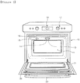
- Fig. 1 is a perspective view of a cooker according to an embodiment.
- Fig. 2 is a schematic view of a cooker according to a first embodiment.
- a cooker according to the current embodiment includes a main body 10 that accommodates a cooking chamber 11.
- the cooking chamber 11 provides a space for cooking food.
- a sensing opening 13 is defined at a side of a top surface of the cooking chamber 11.
- a shield glass 14 is disposed in the sensing opening 13.
- the position of the sensing opening 13 is not limited to the top surface of the cooking chamber 11.
- the sensing opening 13 may be defined in one of both side surfaces of the cooking chamber 11 or a rear surface of the cooking chamber 11.
- a lighting opening 15 is defined at a side of the top surface of the cooking chamber 11.
- a shield glass 16 is disposed in the sensing opening 15.
- the lighting opening 15 is disposed at a side of the top surface of the cooking chamber 11 adjacent to the sensing opening 13, the present disclosure is not limited thereto.
- An input part 17 and a display part 19 are disposed on a front upper portion of the main body 10 corresponding to an upper side of the cooking chamber 11.
- the input part 17 receives a manipulation signal for operating the cooker.
- the display part 19 displays an inner state of the cooking chamber 11 detected by an image sensor 27 to be described later.
- the input part 17 and the display part 19 are disposed on the front upper portion of the main body 10, the present disclosure is not limited thereto.
- the input part 17 and the display part 19 may be disposed on the front left and right portions of the main body 10.
- the cooking chamber 11 is selectively opened and closed by a door 20.
- the front end of the door 20 rotates about a vertical axis thereof in front and rear directions of the main body 10.
- a viewing window 21 is disposed in the door 20.
- a user may directly see the inner state of the cooking chamber 11 through the viewing window 21.
- a central portion of the door 20 may be formed of a transparent or translucent material to provide the viewing window 21.
- a door handle 23 to be grasped by the user is disposed on a front upper end of the door 20 to open and close the door 20.
- a heat source 25 is disposed in the main body 10.
- the heat source 25 heats food in the cooking chamber 11.
- the heat source 25 may include at least one of a high frequency heat source emitting microwaves into the cooking chamber 11 and a radiant heat source and convection heat source respectively supplying radiant heat and convection heat into the cooking chamber 11.
- the image sensor 27 is disposed in the main body 10.
- the image sensor 27 scans the inside of the cooking chamber 11, i.e., food received in the cooking chamber 11.
- the image sensor 27 is disposed at an upper side of the main body 10, i.e., an upper side of the cooking chamber 11 corresponding to an upper side of the sensing opening 13 provided with the shield glass 14.
- a lamp 29 is disposed in the main body 10.
- the lamp 29 illuminates the inside of the cooking chamber 11.
- the lamp 29 is disposed above the lighting opening 15.
- a cooling fan 31 disposed in the main body 10 is adjacent to the image sensor 27.
- the cooling fan 31 generates an air flow for cooling the image sensor 27.
- the cooling fan 31 is separately provided to cool the image sensor 27 in the current embodiment, the image sensor 27 may be cooled by a cooling fan (not shown) for cooling the heat source 25.
- a control part 33 controls operations of the heat source 25, the image sensor 27, and the display part 19.
- the control part 33 controls an operation of the heat source 25 according to a manipulation signal inputted into the input part 17.
- the control part 33 controls the image sensor 27 to scan food and controls the display part 19 to display an image of the scanned food.
- the control part 33 controls the image sensor 27 to scan the food in real time before the heat source 25 is operated and controls the image sensor 27 to stop the operation of the image sensor 27 after the heat source 25 is stopped.
- the control part 33 also controls the display part 19 to operate the display part 19 when the image sensor 27 is operated.
- the operations of the display part 19 and the image sensor 27 may simultaneously start and simultaneously stop.
- the control part 33 determines a cooked degree of the food and whether the cooking is finished through the food image scanned by the image sensor 27 to control an operation of the heat source 25.
- the control part 33 reads an RGB color value of the food from the food image scanned by the image sensor 27 to determine a cooked degree of the food according to a variation depending on an elapsed time in the read RGB color value of the food.
- the control part 33 compares the variation of the read RGB color value of the food to a variation of a reference RGB color value to control an output of the heat source 25.
- the control part 33 controls the heat source 25 to increase the output of the heat source 25 when the variation of the read RGB color value is less than that of the reference RGB color value.
- the control part 33 controls the heat source 25 to increase the output of the heat source 25 when the variation of the read RGB color value is greater than that of the reference RGB color value.
- the control part 33 determines that the cooking of the food is finished when the read RGB color value of the food reaches a preset finish RGB color value. Thus, the control part 33 controls the heat source 25 to stop the operation of the heat source 25 when the read RGB color value of the food reaches the finish RGB color value.
- the reference RGB color value variation and the finish RGB color value represent a variation of the RGB color value of the food depending on an elapsed time in the cooking process of the food according to a kind of food and a RGB color value of the food in a state where the cooking of the food is finished, respectively.
- a RGB color value having a relatively high R value is read before the operation of the heat source 25 starts, i.e., before the cooking.
- a RGB color value having a relatively high Y value is read as the RGB color value of the meat.
- the RGB color value of the meat decrease in R value and increase in Y value.
- the control part 33 controls operations of the lamp 29 and the cooling fan 31.
- the control part 33 controls the lamp 29 and the cooling fan 31 to operate the lamp 29 and the cooling fan 31 before the image sensor 27 is operated or when the image sensor 27 is operated.
- the control part 33 controls the lamp 29 and the cooling fan 31 to stop the operations of the lamp 29 and the cooling fan 31 when the operation of the image sensor 27 is stopped or after the operation of the image sensor 27 is stopped.
- the refrigerant RGB color value variation and the finish RGB color value are stored in a data storage part 35.
- the data storage part 35 stores the reference RGB color value variation and the finish RGB color value according to the kind of food.
- the user rotates the door 20 to shield the cooking chamber 11 in a state where the food is received into the cooking chamber 11. Then, when the user manipulates the input part 17 to input a manipulation signal for cooking the food, the control part 33 controls the heat source 25 to operate the heat source 25. Thus, the food is cooked in the cooking chamber 11.
- the control part 33 controls the image sensor 27 and the lamp 29 to operate the image sensor 27 and the lamp before an operation of the heat source 25 starts.
- the image sensor 27 scans the inner portion of the cooking chamber 11 in real time.
- An image of the food scanned by the image sensor 27 is displayed through the display part 19.
- the control part 33 controls the cooling fan to operate the cooling fan, thereby cooling the image sensor 27.
- control part 33 reads a RGB color value of the food from the food image scanned by the image sensor 27 to compare a variation depending on an elapsed time to the reference RGB color value variation, thereby maintaining, increasing, or decreasing an output of the heat source 25.
- the control part 33 determines whether the read RGB color value of the food reaches the finish RGB color value.
- the control part 33 controls the heat source 25 to stop the operation of the heat source 25.
- the control part 33 controls the image sensor 27, the lamp 29, and the cooling fan 31 to stop the operations of the image sensor 27, the lamp 29, and the cooling fan 31.
- the control part 33 controls the display part 19 to display the food image scanned by the image sensor 27 through the display part 19.
- the user may easily determine the cooked degree of the food and whether the cooking is finished in the cooking chamber 11 from the food image displayed on the display part 19.
- Fig. 3 is a perspective view of a cooker according to a second embodiment.
- the same components as those of the foregoing first embodiment will be denoted by the same reference numerals as those of Figs. 1 and 2 and their detained descriptions will be omitted.
- an image display part 37 for displaying an image of food scanned by an image sensor 27 is disposed on a door 20.
- the image display part 37 is disposed at a center corresponding to the viewing window (see reference numeral 21 of Fig. 1 ) according to the foregoing first embodiment.
- the image display part 37 according to the current embodiment may have a size relatively greater than that of the display part (see reference numeral 19 of Fig. 1 ) according to the foregoing first embodiment.
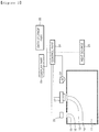
- Fig. 4 is a schematic view illustrating a state in which the cooker according to the embodiment is connected to a network according to a third embodiment.
- the same components as those of the foregoing first embodiment will be denoted by the same reference numerals as those of Figs. 1 and 2 and their detained descriptions will be omitted.
- a cooker according to the current embodiment includes a cooking chamber 11 in which food is cooked by a heat source 25.
- An image sensor 27 scans the food in the cooking chamber 11 to form a food image.
- a display part 19 displays the food image scanned by the image sensor 27.
- a control part 33 controls operations of the image sensor 27 and the display part 19.
- a data storage part 35 stores a reference RGB color value variation and a finish RGB color value according to a kind of food.
- the data storage part 35 may storage recipes and character images transmitted from a terminal 43 that will be described later.
- the character images may be changed according to a cooking process of the food in the cooking chamber 11.
- the cooker according to the current embodiment further includes a communication part 39 communicating with the terminal 43 through a network 41.
- the communication part 39 of the cooker transmits information including the food image scanned by the image sensor 27 into the terminal 43 through the network 41 and receives information from the terminal 43 to transmit the received information.
- the network 41 connects the communication part 39 of the cooker to the terminal 43.
- the network 41 may connect wirelessly the communication part 39 to the terminal 43 or connect the communication part 39 to the terminal 43 through a wired cable.
- the terminal 43 transmits and receives data into/from the cooker through the network 41 at a remote area spaced from the cooker.
- the cooker transmits the food image scanned by the image sensor 27 into the terminal 43.
- the terminal 43 transmits an operation of the cooker, i.e., a manipulation signal for controlling an operation of the heat source 25 into the cooker.
- the cooker transmits data stored in the data storage part 35, i.e., the recipes and character images into the terminal 43.
- the control part 33 reads a RGB color value from the food image scanned by the image sensor 27 to determine a kind of food.
- the control part 33 controls the cooker to transmit the recipes and character images from the cooker to the terminal 43 according to the determined kind of food. That is, the controls determines a kind of food received in the cooking chamber 11 from the read RGB color value of the food to transmit the recipes and character images to the terminal 43 according to the determined kind of food.
- the terminal 43 includes a communication part 39 for communicating with the cooker to transmit/receive data between the cooker and the terminal 43.
- the terminal 43 includes a display part for displaying the food image and an input part 17 for inputting the manipulation signal.
- separate terminals for a computer, mobile phone, the display part 19, and the input part 17 are used as the terminal 43.
- the cooker according to the embodiments has effects as follows.
- the food image scanned by the image sensor may be displayed to the outside.
- the user may more accurately recognize a state of the food.
- the cook image scanned by the image sensor may be wirelessly transmitted into the user disposed at a position spaced from the cooker or transmitted into the user through wired communication.
- the user may more accurately recognize a state of the food.
- the display part for displaying the cook image scanned by the image sensor may be disposed on the front surface of the door for selectively opening and closing the cooking chamber.
- the display part may be easily designed in position.
- the present invention is further defined by the following items:
Landscapes
- Engineering & Computer Science (AREA)
- Chemical & Material Sciences (AREA)
- Combustion & Propulsion (AREA)
- Mechanical Engineering (AREA)
- General Engineering & Computer Science (AREA)
- Physics & Mathematics (AREA)
- Electromagnetism (AREA)
- Electric Ovens (AREA)
- Electric Stoves And Ranges (AREA)
Abstract
Description
- The present disclosure relates to a cooker, and more particularly, to a cooker for scanning food to display a food image.
- Cookers are home appliances for cooking food with electricity or gaseous fuel. Such a cooker includes a heat source for heating food in a cooking chamber. The cooker also includes a temperature sensor or a humidity sensor for sensing temperature or humidity of the cooking chamber. An operation of the heat source is controlled according to a temperature or humidity sensed by the temperature sensor or the humidity sensor, thereby facilitating the cooking of the food in the cooking chamber.
- Embodiments provide a cooker that more accurately detects an inner state of a cooking chamber.
- Embodiments also provide a cooker in which a user more easily recognizes an inner state of a cooking chamber.
- In one embodiment, a cooker includes: a main body including a cooking chamber in which food is cooked; a door selectively opening and closing the cooking chamber; a heat source providing heat for heating the food in the cooking chamber; an image sensor scanning the food in the chamber; a display part displaying an image of the food scanned by the image sensor; and a control part determining a cooked degree and whether the cooking is finished from the image of the food scanned by the image sensor to control an operation of the heat source.
- In another embodiment, a cooker includes: a main body including a cooking chamber in which food is cooked; a door selectively opening and closing the cooking chamber; a heat source providing heat for heating the food in the cooking chamber; an image sensor scanning the food in the chamber; a display part displaying an image of the food scanned by the image sensor; and a communication part transmitting/receiving data into/from an external terminal; a data storage part storing data according to a kind of food; and a control part determining the kind of food cooked in the cooking chamber from an image of the food scanned by the image sensor to transmit data corresponding to the food of the data stored in the data storage part into the terminal through the communication part according to the determined kind of food.
- The details of one or more embodiments are set forth in the accompanying drawings and the description below. Other features will be apparent from the description and drawings, and from the claims.
- According to the embodiments, the user may more easily and accurately recognize the inner state of the cooking chamber.
-
-
Fig. 1 is a perspective view of a cooker according to an embodiment. -
Fig. 2 is a schematic view of a cooker according to a first embodiment. -
Fig. 3 is a perspective view of a cooker according to a second embodiment. -
Fig. 4 is a schematic view illustrating a state in which the cooker according to the embodiment is connected to a network according to a third embodiment. - Hereinafter, a cooker according to a first embodiment will be described in detail with reference to accompanying drawings.
-
Fig. 1 is a perspective view of a cooker according to an embodiment.Fig. 2 is a schematic view of a cooker according to a first embodiment. - Referring to
Figs. 1 and2 , a cooker according to the current embodiment includes amain body 10 that accommodates acooking chamber 11. Thecooking chamber 11 provides a space for cooking food. - A sensing
opening 13 is defined at a side of a top surface of thecooking chamber 11. Ashield glass 14 is disposed in thesensing opening 13. The position of thesensing opening 13 is not limited to the top surface of thecooking chamber 11. For example, thesensing opening 13 may be defined in one of both side surfaces of thecooking chamber 11 or a rear surface of thecooking chamber 11. Alighting opening 15 is defined at a side of the top surface of thecooking chamber 11. - Also, a
shield glass 16 is disposed in the sensing opening 15. Although thelighting opening 15 is disposed at a side of the top surface of thecooking chamber 11 adjacent to thesensing opening 13, the present disclosure is not limited thereto. - An
input part 17 and adisplay part 19 are disposed on a front upper portion of themain body 10 corresponding to an upper side of thecooking chamber 11. Theinput part 17 receives a manipulation signal for operating the cooker. Thedisplay part 19 displays an inner state of thecooking chamber 11 detected by animage sensor 27 to be described later. Although theinput part 17 and thedisplay part 19 are disposed on the front upper portion of themain body 10, the present disclosure is not limited thereto. For example, theinput part 17 and thedisplay part 19 may be disposed on the front left and right portions of themain body 10. - The
cooking chamber 11 is selectively opened and closed by adoor 20. The front end of thedoor 20 rotates about a vertical axis thereof in front and rear directions of themain body 10. Aviewing window 21 is disposed in thedoor 20. A user may directly see the inner state of thecooking chamber 11 through theviewing window 21. For example, a central portion of thedoor 20 may be formed of a transparent or translucent material to provide theviewing window 21. Also, adoor handle 23 to be grasped by the user is disposed on a front upper end of thedoor 20 to open and close thedoor 20. - A
heat source 25 is disposed in themain body 10. Theheat source 25 heats food in thecooking chamber 11. For example, theheat source 25 may include at least one of a high frequency heat source emitting microwaves into thecooking chamber 11 and a radiant heat source and convection heat source respectively supplying radiant heat and convection heat into thecooking chamber 11. - The
image sensor 27 is disposed in themain body 10. Theimage sensor 27 scans the inside of thecooking chamber 11, i.e., food received in thecooking chamber 11. In the current embodiment, theimage sensor 27 is disposed at an upper side of themain body 10, i.e., an upper side of thecooking chamber 11 corresponding to an upper side of thesensing opening 13 provided with theshield glass 14. - Also, a
lamp 29 is disposed in themain body 10. Thelamp 29 illuminates the inside of thecooking chamber 11. Thelamp 29 is disposed above the lighting opening 15. - A
cooling fan 31 disposed in themain body 10 is adjacent to theimage sensor 27. Thecooling fan 31 generates an air flow for cooling theimage sensor 27. Although thecooling fan 31 is separately provided to cool theimage sensor 27 in the current embodiment, theimage sensor 27 may be cooled by a cooling fan (not shown) for cooling theheat source 25. - A
control part 33 controls operations of theheat source 25, theimage sensor 27, and thedisplay part 19. In detail, thecontrol part 33 controls an operation of theheat source 25 according to a manipulation signal inputted into theinput part 17. Thecontrol part 33 controls theimage sensor 27 to scan food and controls thedisplay part 19 to display an image of the scanned food. Here, thecontrol part 33 controls theimage sensor 27 to scan the food in real time before theheat source 25 is operated and controls theimage sensor 27 to stop the operation of theimage sensor 27 after theheat source 25 is stopped. Thecontrol part 33 also controls thedisplay part 19 to operate thedisplay part 19 when theimage sensor 27 is operated. Thus, the operations of thedisplay part 19 and theimage sensor 27 may simultaneously start and simultaneously stop. Also, thecontrol part 33 determines a cooked degree of the food and whether the cooking is finished through the food image scanned by theimage sensor 27 to control an operation of theheat source 25. - In the current embodiment, the
control part 33 reads an RGB color value of the food from the food image scanned by theimage sensor 27 to determine a cooked degree of the food according to a variation depending on an elapsed time in the read RGB color value of the food. Here, thecontrol part 33 compares the variation of the read RGB color value of the food to a variation of a reference RGB color value to control an output of theheat source 25. For example, thecontrol part 33 controls theheat source 25 to increase the output of theheat source 25 when the variation of the read RGB color value is less than that of the reference RGB color value. Also, thecontrol part 33 controls theheat source 25 to increase the output of theheat source 25 when the variation of the read RGB color value is greater than that of the reference RGB color value. - The
control part 33 determines that the cooking of the food is finished when the read RGB color value of the food reaches a preset finish RGB color value. Thus, thecontrol part 33 controls theheat source 25 to stop the operation of theheat source 25 when the read RGB color value of the food reaches the finish RGB color value. - Here, the reference RGB color value variation and the finish RGB color value represent a variation of the RGB color value of the food depending on an elapsed time in the cooking process of the food according to a kind of food and a RGB color value of the food in a state where the cooking of the food is finished, respectively. For example, in case where the food is meat, a RGB color value having a relatively high R value is read before the operation of the
heat source 25 starts, i.e., before the cooking. However, when the meat is cooked and done by the operation of theheat source 25, a RGB color value having a relatively high Y value is read as the RGB color value of the meat. When the food is cooled by the operation of theheat source 25, the RGB color value of the meat decrease in R value and increase in Y value. - The
control part 33 controls operations of thelamp 29 and the coolingfan 31. In the current embodiment, thecontrol part 33 controls thelamp 29 and the coolingfan 31 to operate thelamp 29 and the coolingfan 31 before theimage sensor 27 is operated or when theimage sensor 27 is operated. Also, thecontrol part 33 controls thelamp 29 and the coolingfan 31 to stop the operations of thelamp 29 and the coolingfan 31 when the operation of theimage sensor 27 is stopped or after the operation of theimage sensor 27 is stopped. - The refrigerant RGB color value variation and the finish RGB color value are stored in a
data storage part 35. Here, thedata storage part 35 stores the reference RGB color value variation and the finish RGB color value according to the kind of food. - Hereinafter, an operation of the cooker according to the first embodiment will be described in detail with reference to accompanying drawings.
- The user rotates the
door 20 to shield thecooking chamber 11 in a state where the food is received into thecooking chamber 11. Then, when the user manipulates theinput part 17 to input a manipulation signal for cooking the food, thecontrol part 33 controls theheat source 25 to operate theheat source 25. Thus, the food is cooked in thecooking chamber 11. - The
control part 33 controls theimage sensor 27 and thelamp 29 to operate theimage sensor 27 and the lamp before an operation of theheat source 25 starts. Thus, theimage sensor 27 scans the inner portion of thecooking chamber 11 in real time. An image of the food scanned by theimage sensor 27 is displayed through thedisplay part 19. Thecontrol part 33 controls the cooling fan to operate the cooling fan, thereby cooling theimage sensor 27. - Here, the
control part 33 reads a RGB color value of the food from the food image scanned by theimage sensor 27 to compare a variation depending on an elapsed time to the reference RGB color value variation, thereby maintaining, increasing, or decreasing an output of theheat source 25. - Then, the
control part 33 determines whether the read RGB color value of the food reaches the finish RGB color value. When thecontrol part 33 determines that the read RGB color value of the food reaches the finish RGB color value, thecontrol part 33 controls theheat source 25 to stop the operation of theheat source 25. When the operation of theheat source 25 is stopped, thecontrol part 33 controls theimage sensor 27, thelamp 29, and the coolingfan 31 to stop the operations of theimage sensor 27, thelamp 29, and the coolingfan 31. - The
control part 33 controls thedisplay part 19 to display the food image scanned by theimage sensor 27 through thedisplay part 19. Thus, the user may easily determine the cooked degree of the food and whether the cooking is finished in thecooking chamber 11 from the food image displayed on thedisplay part 19. - Hereinafter, a cooker according to a second embodiment will be described in detail with reference to accompanying drawings.
-
Fig. 3 is a perspective view of a cooker according to a second embodiment. Here, the same components as those of the foregoing first embodiment will be denoted by the same reference numerals as those ofFigs. 1 and2 and their detained descriptions will be omitted. - Referring to
Fig. 3 , animage display part 37 for displaying an image of food scanned by animage sensor 27 is disposed on adoor 20. In detail, theimage display part 37 is disposed at a center corresponding to the viewing window (seereference numeral 21 ofFig. 1 ) according to the foregoing first embodiment. Thus, theimage display part 37 according to the current embodiment may have a size relatively greater than that of the display part (seereference numeral 19 ofFig. 1 ) according to the foregoing first embodiment. - This is done for a reason that enables the user to see a more large food image scanned by the image sensor (see
reference numeral 27 ofFig. 2 ). Also, this is done for a reason that prevents the foods from being inaccurately distinguished through theviewing window 21 due to dew formed on theviewing window 21 in the cooking process of the food. - Hereinafter, a cooker according to a third embodiment will be described in detail with reference to accompanying drawings.
-
Fig. 4 is a schematic view illustrating a state in which the cooker according to the embodiment is connected to a network according to a third embodiment. Here, the same components as those of the foregoing first embodiment will be denoted by the same reference numerals as those ofFigs. 1 and2 and their detained descriptions will be omitted. - Referring to
Fig. 4 , a cooker according to the current embodiment includes acooking chamber 11 in which food is cooked by aheat source 25. Animage sensor 27 scans the food in thecooking chamber 11 to form a food image. Then, adisplay part 19 displays the food image scanned by theimage sensor 27. Acontrol part 33 controls operations of theimage sensor 27 and thedisplay part 19. - A
data storage part 35 stores a reference RGB color value variation and a finish RGB color value according to a kind of food. In the current embodiment, thedata storage part 35 may storage recipes and character images transmitted from a terminal 43 that will be described later. Here, the character images may be changed according to a cooking process of the food in thecooking chamber 11. - The cooker according to the current embodiment further includes a
communication part 39 communicating with the terminal 43 through anetwork 41. Thecommunication part 39 of the cooker transmits information including the food image scanned by theimage sensor 27 into the terminal 43 through thenetwork 41 and receives information from the terminal 43 to transmit the received information. - The
network 41 connects thecommunication part 39 of the cooker to the terminal 43. Thenetwork 41 may connect wirelessly thecommunication part 39 to the terminal 43 or connect thecommunication part 39 to the terminal 43 through a wired cable. The terminal 43 transmits and receives data into/from the cooker through thenetwork 41 at a remote area spaced from the cooker. - For example, the cooker transmits the food image scanned by the
image sensor 27 into the terminal 43. Also, the terminal 43 transmits an operation of the cooker, i.e., a manipulation signal for controlling an operation of theheat source 25 into the cooker. The cooker transmits data stored in thedata storage part 35, i.e., the recipes and character images into the terminal 43. Here, thecontrol part 33 reads a RGB color value from the food image scanned by theimage sensor 27 to determine a kind of food. Thus, thecontrol part 33 controls the cooker to transmit the recipes and character images from the cooker to the terminal 43 according to the determined kind of food. That is, the controls determines a kind of food received in thecooking chamber 11 from the read RGB color value of the food to transmit the recipes and character images to the terminal 43 according to the determined kind of food. - The terminal 43 includes a
communication part 39 for communicating with the cooker to transmit/receive data between the cooker and the terminal 43. The terminal 43 includes a display part for displaying the food image and aninput part 17 for inputting the manipulation signal. Here, separate terminals for a computer, mobile phone, thedisplay part 19, and theinput part 17 are used as the terminal 43. - It should be understood that numerous other modifications and embodiments can be devised by those skilled in the art that will fall within the spirit and scope of the principles of this disclosure. More particularly, various variations and modifications are possible in the component parts and/or arrangements of the subject combination arrangement within the scope of the disclosure, the drawings and the appended claims.
- As described above, the cooker according to the embodiments has effects as follows.
- The food image scanned by the image sensor may be displayed to the outside. Thus, the user may more accurately recognize a state of the food.
- Also, the cook image scanned by the image sensor may be wirelessly transmitted into the user disposed at a position spaced from the cooker or transmitted into the user through wired communication. Thus, the user may more accurately recognize a state of the food.
- Also, the display part for displaying the cook image scanned by the image sensor may be disposed on the front surface of the door for selectively opening and closing the cooking chamber. Thus, the display part may be easily designed in position.
- The present invention is further defined by the following items:
- 1. A cooker comprising:
- a main body comprising a cooking chamber in which food is cooked;
- a door selectively opening and closing the cooking chamber;
- a heat source providing heat for heating the food in the cooking chamber;
- an image sensor scanning the food in the chamber;
- a display part displaying an image of the food scanned by the image sensor; and
- a control part determining a cooked degree and whether the cooking is finished from the image of the food scanned by the image sensor to control an operation of the heat source.
- 2. The cooker according to item 1, wherein the control part reads a RGB color value of the food from the image of the food scanned by the image sensor to determine the cooked degree of the food according to a variation of the read RGB color value of the food according to an elapsed time.
- 3. The cooker according to item 2, wherein the control part controls the heat source to increase heat provided from the heat source into the cooking chamber when the variation of the read RGB color value of the food is less than a preset reference RGB color value variation and to decrease heat provided from the heat source into the cooking chamber when the variation of the read RGB color value of the food exceeds the reference RGB color value variation.
- 4. The cooker according to item 2, wherein the control part stops an operation of the heat source when the read RGB color value of the food reaches a preset finish RGB color value.
- 5. The cooker according to item 1, further comprising a communication part for transmitting/receiving data into/from an external terminal.
- 6. The cooker according to item 5, wherein the data transmitted into the terminal by the communication part comprises an image of the food scanned by at least the image sensor.
- 7. The cooker according to item 5, wherein the data received from the terminal by the communication part comprises a manipulation signal for controlling an operation of the heat source.
- 8. A cooker comprising:
- a main body comprising a cooking chamber in which food is cooked;
- a door selectively opening and closing the cooking chamber;
- a heat source providing heat for heating the food in the cooking chamber;
- an image sensor scanning the food in the chamber;
- a display part displaying an image of the food scanned by the image sensor; and
- a communication part transmitting/receiving data into/from an external terminal;
- a data storage part storing data according to a kind of food; and
- a control part determining the kind of food cooked in the cooking chamber from an image of the food scanned by the image sensor to transmit data corresponding to the food of the data stored in the data storage part into the terminal through the communication part according to the determined kind of food.
- 9. The cooker according to item 8, wherein the control part reads a RGB color value of the food from the image of the food scanned by the image sensor to determine a kind of food according to the read RGB color value of the food.
- 10. The cooker according to item 8, wherein the data stored in the data storage part comprises at least recipe of the food and at least character image changed according to a cooking process of the food.
- 11. The cooker according to item 8, wherein the communication part is connected wirelessly to the terminal or connected the terminal through a wired cable.
- 12. A method of controlling a cooker, the method comprising:
- scanning an image of food through an image sensor;
- providing heat for heating the food from a heat source;
- reading a RGB color value of the food changed by the heat provided by the heat source from the image of the food scanned by the image sensor through a control part;
- determining a cooked degree of the food according to a variation of the read RGB color value of the food depending on an elapsed time through the control part; and
- controlling an operation of the heat source according to the determined cooked degree of the food through the control part.
- 13. The method according to item 12, wherein the control part controls the heat source to increase heat provided from the heat source into the cooking chamber when the variation of the read RGB color value of the food is less than a preset reference RGB color value variation and to decrease heat provided from the heat source into the cooking chamber when the variation of the read RGB color value of the food exceeds the reference RGB color value variation.
- 14. The method according to item 12, wherein the control part stops an operation of the heat source when the read RGB color value of the food reaches a preset finish RGB color value.
- 15. The method according to item 12, further comprising transmitting data comprising the image of the food scanned by at least the image sensor into an external terminal through the communication part.
- 16. A method of controlling a cooker, the method comprising:
- scanning an image of food through an image sensor;
- providing heat for heating the food from a heat source;
- reading a RGB color value of the food changed by the heat provided by the heat source from the image of the food scanned by the image sensor through a control part;
- comparing a variation of the read RGB color value of the food depending on an elapsed time to a finish color value variation through the control part to determine a cooked degree of the food and whether the cooking is finished; and
- controlling an operation of the heat source through the control part according to the determined cooked degree of the food and whether the cooking is finished.
- 17. The method according to
item 16, wherein the control part controls the heat source to increase heat provided from the heat source into the cooking chamber in the controlling of the heat source when the variation of the read RGB color value of the food is less than a preset reference RGB color value variation in the determining of the cooked degree, and
the control part controls the heat source to decrease heat provided from the heat source into the cooking chamber in the controlling of the heat source when the variation of the read RGB color value of the food exceeds the reference RGB color value variation in the determined of the cooked degree. - 18. The method according to
item 16, wherein the control part stops an operation of the heat source in the controlling of the heat source when the read RGB color value of the food reaches a preset finish RGB color value in the determined of the cooked degree. - 19. The method according to
item 16, further comprising transmitting/receiving data comprising the image of the food scanned by at least the image sensor into an external terminal through a communication part.
Claims (12)
- A cooker comprising:a main body (10) including a cooking chamber (11) configured to receive food which is cooked;a door (20) configured to selectively open and close the cooking chamber (11);a heat source (25) configured to provide heat for heating the food in the cooking chamber (11);an image sensor (27) to scan the food in the cooking chamber (11);a lamp (29) provided in the main body (10) to illuminate inside the cooking chamber;a cooling fan (31) provided in the main body (1) to cool the image sensor (27);a communication part (33) configured to transmit/receive data into/from an external terminal (43); anda control part (33) configured to control the heat source (25), the image sensor (27), the lamp (29) and the cooling fan (31).
- The cooker according to claim 1, wherein the control part (33) is configured to control the image sensor (27) to scan the food in real time before the heat source (25) is operated and to control the image sensor (27) to stop the operation of the image sensor (27) after the heat source (25) is stopped.
- The cooker according to claim 1 or 2, further comprising a display (19) disposed on the main body (10) to display a food image scanned by the image sensor (27),
wherein the control part (33) is configured to control the display part (19) to display the scanned food image when the image sensor (27) is operated. - The cooker according to claim 3, wherein the operations of the display part (19) and the image sensor (27) simultaneously start and simultaneously stop.
- The cooker according to any one of claims 1 to 4, wherein the control part (33) is configured to control the lamp (29) and the cooling fan (31) to operate the lamp (29) and the cooling fan (31) before the image sensor (27) is operated or when the image sensor (27) is operated.
- The cooker according to any one of claims 1 to 5, wherein the control part (33) is configured to control the lamp (29) and the cooling fan (31) to stop the operations of the lamp (29) and the cooling fan (31) when the operation of the image sensor (27) is stopped or after the operation of the image sensor (27) is stopped.
- The cooker according to any one of claims 1 to 6, wherein the cooling fan (31) is adjacent to the image sensor to cool the image sensor (27).
- The cooker according to any one of claims 1 to 7, further comprising a sensing opening (13) defined at a top surface of the cooking chamber (11), and
a shield glass (14) disposed in the sensing opening (13). - The cooker according to any one of claims 1 to 8, further comprising a lighting opening (15) defined at a top surface of the cooking chamber (11), and
a shield glass (16) disposed in the lighting opening (15). - The cooker according to any one of claims 1 to 9, wherein the control part (33) is configured to determine a cooked degree of the food and whether the cooking is finished from the food image scanned by the image sensor (27) to control an operation of the heat source (25).
- The cooker according to any one of claims 1 to 10, wherein the communication part (33) transmits information including a food image scanned by the image sensor (27) into the external terminal (43).
- The cooker according to any one of claims 1 to 11, further comprising a data storage part (35) configured to store at least one of recipes and character image according to a kind of food.
Applications Claiming Priority (3)
| Application Number | Priority Date | Filing Date | Title |
|---|---|---|---|
| KR1020090053050A KR101044143B1 (en) | 2009-06-15 | 2009-06-15 | Cooker |
| PCT/KR2010/003844 WO2010147370A2 (en) | 2009-06-15 | 2010-06-15 | Cooker and control method thereof |
| EP10789697.9A EP2444735B1 (en) | 2009-06-15 | 2010-06-15 | Cooker and control method thereof |
Related Parent Applications (2)
| Application Number | Title | Priority Date | Filing Date |
|---|---|---|---|
| EP10789697.9A Division EP2444735B1 (en) | 2009-06-15 | 2010-06-15 | Cooker and control method thereof |
| EP10789697.9A Division-Into EP2444735B1 (en) | 2009-06-15 | 2010-06-15 | Cooker and control method thereof |
Publications (2)
| Publication Number | Publication Date |
|---|---|
| EP3346191A1 true EP3346191A1 (en) | 2018-07-11 |
| EP3346191B1 EP3346191B1 (en) | 2020-10-07 |
Family
ID=43356896
Family Applications (2)
| Application Number | Title | Priority Date | Filing Date |
|---|---|---|---|
| EP10789697.9A Active EP2444735B1 (en) | 2009-06-15 | 2010-06-15 | Cooker and control method thereof |
| EP18152931.4A Active EP3346191B1 (en) | 2009-06-15 | 2010-06-15 | Cooker |
Family Applications Before (1)
| Application Number | Title | Priority Date | Filing Date |
|---|---|---|---|
| EP10789697.9A Active EP2444735B1 (en) | 2009-06-15 | 2010-06-15 | Cooker and control method thereof |
Country Status (4)
| Country | Link |
|---|---|
| US (1) | US20120076351A1 (en) |
| EP (2) | EP2444735B1 (en) |
| KR (1) | KR101044143B1 (en) |
| WO (1) | WO2010147370A2 (en) |
Families Citing this family (41)
| Publication number | Priority date | Publication date | Assignee | Title |
|---|---|---|---|---|
| KR101909027B1 (en) * | 2011-08-22 | 2018-10-17 | 엘지전자 주식회사 | An information management system for home appliance |
| EP2798273A1 (en) * | 2011-12-26 | 2014-11-05 | Arçelik Anonim Sirketi | Oven with optical detection means |
| EP2662628B1 (en) * | 2012-05-08 | 2019-11-27 | Electrolux Home Products Corporation N.V. | Appliance for processing food and method of operating the same |
| US20140104385A1 (en) * | 2012-10-16 | 2014-04-17 | Sony Network Entertainment International Llc | Method and apparatus for determining information associated with a food product |
| DE102013102295A1 (en) * | 2013-03-07 | 2014-09-11 | Rational Ag | Method for adapting a food cooking process |
| EP3598005B1 (en) * | 2014-06-05 | 2021-11-24 | Stork genannt Wersborg, Ingo | Food heat treatment monitoring system |
| WO2016128370A1 (en) * | 2015-02-10 | 2016-08-18 | Electrolux Appliances Aktiebolag | Oven door and oven comprising an oven door |
| US10739013B2 (en) | 2015-05-05 | 2020-08-11 | June Life, Inc. | Tailored food preparation with an oven |
| CN107535024B (en) | 2015-05-05 | 2020-11-27 | 俊生活公司 | Linked food preparation system and method of use |
| US9927129B2 (en) * | 2015-06-01 | 2018-03-27 | June Life, Inc. | Thermal management system and method for a connected oven |
| USD787041S1 (en) | 2015-09-17 | 2017-05-16 | Whirlpool Corporation | Gas burner |
| US10837651B2 (en) | 2015-09-24 | 2020-11-17 | Whirlpool Corporation | Oven cavity connector for operating power accessory trays for cooking appliance |
| US20170134652A1 (en) * | 2015-11-06 | 2017-05-11 | L-3 Communications Corporation | Viewport for imaging in an rf/microwave environment |
| US11777190B2 (en) | 2015-12-29 | 2023-10-03 | Whirlpool Corporation | Appliance including an antenna using a portion of appliance as a ground plane |
| US10145568B2 (en) | 2016-06-27 | 2018-12-04 | Whirlpool Corporation | High efficiency high power inner flame burner |
| WO2018044067A1 (en) | 2016-09-01 | 2018-03-08 | Samsung Electronics Co., Ltd. | Oven |
| CN106419498A (en) * | 2016-10-27 | 2017-02-22 | 广东格兰仕集团有限公司 | Cooking equipment controlling firepower and time based on image recognition and control method thereof |
| US10551056B2 (en) | 2017-02-23 | 2020-02-04 | Whirlpool Corporation | Burner base |
| US10451290B2 (en) | 2017-03-07 | 2019-10-22 | Whirlpool Corporation | Forced convection steam assembly |
| US10660162B2 (en) | 2017-03-16 | 2020-05-19 | Whirlpool Corporation | Power delivery system for an induction cooktop with multi-output inverters |
| KR102366006B1 (en) * | 2017-06-20 | 2022-02-23 | 삼성전자주식회사 | Oven |
| KR101955876B1 (en) * | 2017-07-28 | 2019-05-30 | 엘지전자 주식회사 | Oven and controlling method thereof |
| US20190110638A1 (en) * | 2017-10-16 | 2019-04-18 | Midea Group Co., Ltd | Machine learning control of cooking appliances |
| TR201717330A2 (en) | 2017-11-06 | 2019-05-21 | Arcelik As | AN OVEN AND EXTERNAL DEVICE |
| TR201717412A2 (en) | 2017-11-07 | 2019-05-21 | Arcelik As | AN OVEN |
| CN107908144B (en) * | 2017-11-24 | 2020-09-18 | 北京小米移动软件有限公司 | Method and device for controlling smoke extractor and storage medium |
| US11116050B1 (en) | 2018-02-08 | 2021-09-07 | June Life, Inc. | High heat in-situ camera systems and operation methods |
| US11206946B2 (en) * | 2018-03-21 | 2021-12-28 | Marmon Foodservice Technologies, Inc. | Heat transfer system |
| US10627116B2 (en) | 2018-06-26 | 2020-04-21 | Whirlpool Corporation | Ventilation system for cooking appliance |
| US10619862B2 (en) | 2018-06-28 | 2020-04-14 | Whirlpool Corporation | Frontal cooling towers for a ventilation system of a cooking appliance |
| US10837652B2 (en) | 2018-07-18 | 2020-11-17 | Whirlpool Corporation | Appliance secondary door |
| US20200154943A1 (en) * | 2018-11-16 | 2020-05-21 | GMG Products LLC | Imaging system for cooking device |
| CN109730520B (en) * | 2018-11-30 | 2021-08-17 | 深圳和而泰智能控制股份有限公司 | Food heating control method and device, computer equipment and readable storage medium |
| US11287140B2 (en) * | 2019-01-04 | 2022-03-29 | Whirlpool Corporation | Cooking appliance with an imaging device |
| US11022322B2 (en) * | 2019-01-04 | 2021-06-01 | Whirlpool Corporation | Cooking appliance with an imaging device |
| WO2021195622A1 (en) | 2020-03-27 | 2021-09-30 | June Life, Inc. | System and method for classification of ambiguous objects |
| BE1028761B1 (en) | 2020-10-29 | 2022-05-31 | Miele & Cie | Method for operating a cooking appliance and cooking appliance |
| US11940153B2 (en) | 2020-12-01 | 2024-03-26 | GMG Products, LLC | Fuel conditioner for grill |
| DE102020132420A1 (en) | 2020-12-07 | 2022-06-09 | Miele & Cie. Kg | Method for operating a cooking appliance and cooking appliance |
| US11747087B2 (en) * | 2021-01-06 | 2023-09-05 | Bsh Home Appliances Corporation | Household appliance including reflective door |
| CN113015278A (en) * | 2021-02-01 | 2021-06-22 | 惠而浦公司 | Transparent metal coating for camera panes in microwave ovens |
Citations (5)
| Publication number | Priority date | Publication date | Assignee | Title |
|---|---|---|---|---|
| EP0563698A2 (en) * | 1992-04-02 | 1993-10-06 | ZELTRON S.p.A. | Automatically controlled cooking system |
| JPH0821631A (en) * | 1994-07-05 | 1996-01-23 | Hitachi Home Tec Ltd | High-frequency heating appliance |
| EP1028604A2 (en) * | 1999-02-09 | 2000-08-16 | Ncr International Inc. | Domestic appliance with camera to display images of cooking or defrosting food |
| EP1382912A1 (en) * | 2001-03-22 | 2004-01-21 | Matsushita Electric Industrial Co., Ltd. | Cooking-related information providing system, cooking-related information providing apparatus, cooking apparatus, cooking-related information providing method, cooking-related information fetch method, cooking-related information providing program, and cooking-related information fetch program |
| DE102007048834A1 (en) * | 2006-10-17 | 2008-04-24 | BSH Bosch und Siemens Hausgeräte GmbH | Domestic appliance e.g. domestic oven, for treating food arranged in image area of camera, has control unit to produce control signal depending on image data and to determine browning level of cooking goods arranged in image area of camera |
Family Cites Families (5)
| Publication number | Priority date | Publication date | Assignee | Title |
|---|---|---|---|---|
| JP2001272045A (en) * | 2000-03-27 | 2001-10-05 | Sanyo Electric Co Ltd | Oven cooker |
| KR100605841B1 (en) * | 2004-06-03 | 2006-08-01 | 삼성전자주식회사 | Apparatus and method for compensation of correlated color temperature of gray scale in lce |
| US20060081135A1 (en) * | 2004-08-16 | 2006-04-20 | Britton Douglas F | Industrial overline imaging system and method |
| US7913615B2 (en) * | 2006-04-28 | 2011-03-29 | Restaurant Technology, Inc. | Automated dual cooking surface grill and method |
| DE102008042804B4 (en) * | 2007-10-16 | 2013-07-04 | BSH Bosch und Siemens Hausgeräte GmbH | Cooking appliance with camera and method for operating a cooking appliance with camera |
-
2009
- 2009-06-15 KR KR1020090053050A patent/KR101044143B1/en active IP Right Grant
-
2010
- 2010-06-15 WO PCT/KR2010/003844 patent/WO2010147370A2/en active Application Filing
- 2010-06-15 EP EP10789697.9A patent/EP2444735B1/en active Active
- 2010-06-15 US US13/376,792 patent/US20120076351A1/en not_active Abandoned
- 2010-06-15 EP EP18152931.4A patent/EP3346191B1/en active Active
Patent Citations (5)
| Publication number | Priority date | Publication date | Assignee | Title |
|---|---|---|---|---|
| EP0563698A2 (en) * | 1992-04-02 | 1993-10-06 | ZELTRON S.p.A. | Automatically controlled cooking system |
| JPH0821631A (en) * | 1994-07-05 | 1996-01-23 | Hitachi Home Tec Ltd | High-frequency heating appliance |
| EP1028604A2 (en) * | 1999-02-09 | 2000-08-16 | Ncr International Inc. | Domestic appliance with camera to display images of cooking or defrosting food |
| EP1382912A1 (en) * | 2001-03-22 | 2004-01-21 | Matsushita Electric Industrial Co., Ltd. | Cooking-related information providing system, cooking-related information providing apparatus, cooking apparatus, cooking-related information providing method, cooking-related information fetch method, cooking-related information providing program, and cooking-related information fetch program |
| DE102007048834A1 (en) * | 2006-10-17 | 2008-04-24 | BSH Bosch und Siemens Hausgeräte GmbH | Domestic appliance e.g. domestic oven, for treating food arranged in image area of camera, has control unit to produce control signal depending on image data and to determine browning level of cooking goods arranged in image area of camera |
Also Published As
| Publication number | Publication date |
|---|---|
| WO2010147370A3 (en) | 2011-03-17 |
| EP2444735A4 (en) | 2012-11-21 |
| US20120076351A1 (en) | 2012-03-29 |
| KR101044143B1 (en) | 2011-06-24 |
| EP2444735A2 (en) | 2012-04-25 |
| EP3346191B1 (en) | 2020-10-07 |
| KR20100134430A (en) | 2010-12-23 |
| EP2444735B1 (en) | 2018-02-28 |
| WO2010147370A2 (en) | 2010-12-23 |
Similar Documents
| Publication | Publication Date | Title |
|---|---|---|
| EP3346191A1 (en) | Cooker | |
| EP2444734B1 (en) | Cooker and control unit | |
| EP3348910B1 (en) | Cooker | |
| EP3348911B1 (en) | Cooker | |
| EP3677841A1 (en) | Cooking appliance with an imaging device | |
| CN108351107A (en) | Oven and oven door method for opening and closing | |
| KR20220049437A (en) | Cooking equipment with camera | |
| KR20140039733A (en) | Cooking apparatus | |
| US20160290655A1 (en) | Cooking apparatus | |
| US20240053025A1 (en) | Cooking appliance and control method therefor | |
| KR102331087B1 (en) | Commercial microwave oven | |
| EP3677842A1 (en) | Cooking appliance with an imaging device | |
| US11988450B2 (en) | Cooking appliance having an imaging device for identifying a type of temperature sensing device | |
| KR20100134419A (en) | Cooker and method for controlling the same | |
| US20240155744A1 (en) | Heating cooker, computer program, and heating cooking method | |
| KR101044137B1 (en) | Cooker and method for cotrolling the same | |
| KR100634369B1 (en) | Microwave oven having fermenter | |
| US20240070908A1 (en) | Cooking apparatus and method for controlling cooking apparatus | |
| CN211290179U (en) | Commercial microwave oven | |
| US20240071077A1 (en) | Cooking apparatus and method of controlling the same | |
| KR20100134421A (en) | Cooker and method for controlling the same |
Legal Events
| Date | Code | Title | Description |
|---|---|---|---|
| PUAI | Public reference made under article 153(3) epc to a published international application that has entered the european phase |
Free format text: ORIGINAL CODE: 0009012 |
|
| STAA | Information on the status of an ep patent application or granted ep patent |
Free format text: STATUS: REQUEST FOR EXAMINATION WAS MADE |
|
| 17P | Request for examination filed |
Effective date: 20180223 |
|
| AC | Divisional application: reference to earlier application |
Ref document number: 2444735 Country of ref document: EP Kind code of ref document: P |
|
| AK | Designated contracting states |
Kind code of ref document: A1 Designated state(s): AL AT BE BG CH CY CZ DE DK EE ES FI FR GB GR HR HU IE IS IT LI LT LU LV MC MK MT NL NO PL PT RO SE SI SK SM TR |
|
| RBV | Designated contracting states (corrected) |
Designated state(s): AL AT BE BG CH CY CZ DE DK EE ES FI FR GB GR HR HU IE IS IT LI LT LU LV MC MK MT NL NO PL PT RO SE SI SK SM TR |
|
| R17P | Request for examination filed (corrected) |
Effective date: 20180223 |
|
| GRAP | Despatch of communication of intention to grant a patent |
Free format text: ORIGINAL CODE: EPIDOSNIGR1 |
|
| STAA | Information on the status of an ep patent application or granted ep patent |
Free format text: STATUS: GRANT OF PATENT IS INTENDED |
|
| INTG | Intention to grant announced |
Effective date: 20200417 |
|
| GRAS | Grant fee paid |
Free format text: ORIGINAL CODE: EPIDOSNIGR3 |
|
| GRAJ | Information related to disapproval of communication of intention to grant by the applicant or resumption of examination proceedings by the epo deleted |
Free format text: ORIGINAL CODE: EPIDOSDIGR1 |
|
| GRAL | Information related to payment of fee for publishing/printing deleted |
Free format text: ORIGINAL CODE: EPIDOSDIGR3 |
|
| STAA | Information on the status of an ep patent application or granted ep patent |
Free format text: STATUS: REQUEST FOR EXAMINATION WAS MADE |
|
| GRAR | Information related to intention to grant a patent recorded |
Free format text: ORIGINAL CODE: EPIDOSNIGR71 |
|
| STAA | Information on the status of an ep patent application or granted ep patent |
Free format text: STATUS: GRANT OF PATENT IS INTENDED |
|
| GRAA | (expected) grant |
Free format text: ORIGINAL CODE: 0009210 |
|
| STAA | Information on the status of an ep patent application or granted ep patent |
Free format text: STATUS: THE PATENT HAS BEEN GRANTED |
|
| INTC | Intention to grant announced (deleted) | ||
| INTG | Intention to grant announced |
Effective date: 20200827 |
|
| AC | Divisional application: reference to earlier application |
Ref document number: 2444735 Country of ref document: EP Kind code of ref document: P |
|
| AK | Designated contracting states |
Kind code of ref document: B1 Designated state(s): AL AT BE BG CH CY CZ DE DK EE ES FI FR GB GR HR HU IE IS IT LI LT LU LV MC MK MT NL NO PL PT RO SE SI SK SM TR |
|
| REG | Reference to a national code |
Ref country code: GB Ref legal event code: FG4D |
|
| REG | Reference to a national code |
Ref country code: CH Ref legal event code: EP Ref country code: AT Ref legal event code: REF Ref document number: 1321544 Country of ref document: AT Kind code of ref document: T Effective date: 20201015 |
|
| REG | Reference to a national code |
Ref country code: IE Ref legal event code: FG4D |
|
| REG | Reference to a national code |
Ref country code: DE Ref legal event code: R096 Ref document number: 602010065659 Country of ref document: DE |
|
| REG | Reference to a national code |
Ref country code: NL Ref legal event code: MP Effective date: 20201007 |
|
| REG | Reference to a national code |
Ref country code: AT Ref legal event code: MK05 Ref document number: 1321544 Country of ref document: AT Kind code of ref document: T Effective date: 20201007 |
|
| PG25 | Lapsed in a contracting state [announced via postgrant information from national office to epo] |
Ref country code: NO Free format text: LAPSE BECAUSE OF FAILURE TO SUBMIT A TRANSLATION OF THE DESCRIPTION OR TO PAY THE FEE WITHIN THE PRESCRIBED TIME-LIMIT Effective date: 20210107 Ref country code: GR Free format text: LAPSE BECAUSE OF FAILURE TO SUBMIT A TRANSLATION OF THE DESCRIPTION OR TO PAY THE FEE WITHIN THE PRESCRIBED TIME-LIMIT Effective date: 20210108 Ref country code: FI Free format text: LAPSE BECAUSE OF FAILURE TO SUBMIT A TRANSLATION OF THE DESCRIPTION OR TO PAY THE FEE WITHIN THE PRESCRIBED TIME-LIMIT Effective date: 20201007 Ref country code: PT Free format text: LAPSE BECAUSE OF FAILURE TO SUBMIT A TRANSLATION OF THE DESCRIPTION OR TO PAY THE FEE WITHIN THE PRESCRIBED TIME-LIMIT Effective date: 20210208 |
|
| REG | Reference to a national code |
Ref country code: LT Ref legal event code: MG4D |
|
| PG25 | Lapsed in a contracting state [announced via postgrant information from national office to epo] |
Ref country code: ES Free format text: LAPSE BECAUSE OF FAILURE TO SUBMIT A TRANSLATION OF THE DESCRIPTION OR TO PAY THE FEE WITHIN THE PRESCRIBED TIME-LIMIT Effective date: 20201007 Ref country code: AT Free format text: LAPSE BECAUSE OF FAILURE TO SUBMIT A TRANSLATION OF THE DESCRIPTION OR TO PAY THE FEE WITHIN THE PRESCRIBED TIME-LIMIT Effective date: 20201007 Ref country code: SE Free format text: LAPSE BECAUSE OF FAILURE TO SUBMIT A TRANSLATION OF THE DESCRIPTION OR TO PAY THE FEE WITHIN THE PRESCRIBED TIME-LIMIT Effective date: 20201007 Ref country code: PL Free format text: LAPSE BECAUSE OF FAILURE TO SUBMIT A TRANSLATION OF THE DESCRIPTION OR TO PAY THE FEE WITHIN THE PRESCRIBED TIME-LIMIT Effective date: 20201007 Ref country code: IS Free format text: LAPSE BECAUSE OF FAILURE TO SUBMIT A TRANSLATION OF THE DESCRIPTION OR TO PAY THE FEE WITHIN THE PRESCRIBED TIME-LIMIT Effective date: 20210207 Ref country code: LV Free format text: LAPSE BECAUSE OF FAILURE TO SUBMIT A TRANSLATION OF THE DESCRIPTION OR TO PAY THE FEE WITHIN THE PRESCRIBED TIME-LIMIT Effective date: 20201007 Ref country code: BG Free format text: LAPSE BECAUSE OF FAILURE TO SUBMIT A TRANSLATION OF THE DESCRIPTION OR TO PAY THE FEE WITHIN THE PRESCRIBED TIME-LIMIT Effective date: 20210107 |
|
| PG25 | Lapsed in a contracting state [announced via postgrant information from national office to epo] |
Ref country code: HR Free format text: LAPSE BECAUSE OF FAILURE TO SUBMIT A TRANSLATION OF THE DESCRIPTION OR TO PAY THE FEE WITHIN THE PRESCRIBED TIME-LIMIT Effective date: 20201007 Ref country code: NL Free format text: LAPSE BECAUSE OF FAILURE TO SUBMIT A TRANSLATION OF THE DESCRIPTION OR TO PAY THE FEE WITHIN THE PRESCRIBED TIME-LIMIT Effective date: 20201007 |
|
| REG | Reference to a national code |
Ref country code: DE Ref legal event code: R097 Ref document number: 602010065659 Country of ref document: DE |
|
| PG25 | Lapsed in a contracting state [announced via postgrant information from national office to epo] |
Ref country code: EE Free format text: LAPSE BECAUSE OF FAILURE TO SUBMIT A TRANSLATION OF THE DESCRIPTION OR TO PAY THE FEE WITHIN THE PRESCRIBED TIME-LIMIT Effective date: 20201007 Ref country code: CZ Free format text: LAPSE BECAUSE OF FAILURE TO SUBMIT A TRANSLATION OF THE DESCRIPTION OR TO PAY THE FEE WITHIN THE PRESCRIBED TIME-LIMIT Effective date: 20201007 Ref country code: LT Free format text: LAPSE BECAUSE OF FAILURE TO SUBMIT A TRANSLATION OF THE DESCRIPTION OR TO PAY THE FEE WITHIN THE PRESCRIBED TIME-LIMIT Effective date: 20201007 Ref country code: SM Free format text: LAPSE BECAUSE OF FAILURE TO SUBMIT A TRANSLATION OF THE DESCRIPTION OR TO PAY THE FEE WITHIN THE PRESCRIBED TIME-LIMIT Effective date: 20201007 Ref country code: SK Free format text: LAPSE BECAUSE OF FAILURE TO SUBMIT A TRANSLATION OF THE DESCRIPTION OR TO PAY THE FEE WITHIN THE PRESCRIBED TIME-LIMIT Effective date: 20201007 Ref country code: RO Free format text: LAPSE BECAUSE OF FAILURE TO SUBMIT A TRANSLATION OF THE DESCRIPTION OR TO PAY THE FEE WITHIN THE PRESCRIBED TIME-LIMIT Effective date: 20201007 |
|
| PGFP | Annual fee paid to national office [announced via postgrant information from national office to epo] |
Ref country code: FR Payment date: 20210506 Year of fee payment: 12 Ref country code: IT Payment date: 20210609 Year of fee payment: 12 |
|
| PLBE | No opposition filed within time limit |
Free format text: ORIGINAL CODE: 0009261 |
|
| STAA | Information on the status of an ep patent application or granted ep patent |
Free format text: STATUS: NO OPPOSITION FILED WITHIN TIME LIMIT |
|
| PG25 | Lapsed in a contracting state [announced via postgrant information from national office to epo] |
Ref country code: DK Free format text: LAPSE BECAUSE OF FAILURE TO SUBMIT A TRANSLATION OF THE DESCRIPTION OR TO PAY THE FEE WITHIN THE PRESCRIBED TIME-LIMIT Effective date: 20201007 |
|
| 26N | No opposition filed |
Effective date: 20210708 |
|
| PG25 | Lapsed in a contracting state [announced via postgrant information from national office to epo] |
Ref country code: AL Free format text: LAPSE BECAUSE OF FAILURE TO SUBMIT A TRANSLATION OF THE DESCRIPTION OR TO PAY THE FEE WITHIN THE PRESCRIBED TIME-LIMIT Effective date: 20201007 |
|
| PG25 | Lapsed in a contracting state [announced via postgrant information from national office to epo] |
Ref country code: SI Free format text: LAPSE BECAUSE OF FAILURE TO SUBMIT A TRANSLATION OF THE DESCRIPTION OR TO PAY THE FEE WITHIN THE PRESCRIBED TIME-LIMIT Effective date: 20201007 |
|
| PG25 | Lapsed in a contracting state [announced via postgrant information from national office to epo] |
Ref country code: MC Free format text: LAPSE BECAUSE OF FAILURE TO SUBMIT A TRANSLATION OF THE DESCRIPTION OR TO PAY THE FEE WITHIN THE PRESCRIBED TIME-LIMIT Effective date: 20201007 |
|
| REG | Reference to a national code |
Ref country code: CH Ref legal event code: PL |
|
| GBPC | Gb: european patent ceased through non-payment of renewal fee |
Effective date: 20210615 |
|
| REG | Reference to a national code |
Ref country code: BE Ref legal event code: MM Effective date: 20210630 |
|
| PG25 | Lapsed in a contracting state [announced via postgrant information from national office to epo] |
Ref country code: LU Free format text: LAPSE BECAUSE OF NON-PAYMENT OF DUE FEES Effective date: 20210615 |
|
| PG25 | Lapsed in a contracting state [announced via postgrant information from national office to epo] |
Ref country code: LI Free format text: LAPSE BECAUSE OF NON-PAYMENT OF DUE FEES Effective date: 20210630 Ref country code: IE Free format text: LAPSE BECAUSE OF NON-PAYMENT OF DUE FEES Effective date: 20210615 Ref country code: GB Free format text: LAPSE BECAUSE OF NON-PAYMENT OF DUE FEES Effective date: 20210615 Ref country code: CH Free format text: LAPSE BECAUSE OF NON-PAYMENT OF DUE FEES Effective date: 20210630 |
|
| PG25 | Lapsed in a contracting state [announced via postgrant information from national office to epo] |
Ref country code: IS Free format text: LAPSE BECAUSE OF FAILURE TO SUBMIT A TRANSLATION OF THE DESCRIPTION OR TO PAY THE FEE WITHIN THE PRESCRIBED TIME-LIMIT Effective date: 20210207 |
|
| PG25 | Lapsed in a contracting state [announced via postgrant information from national office to epo] |
Ref country code: BE Free format text: LAPSE BECAUSE OF NON-PAYMENT OF DUE FEES Effective date: 20210630 |
|
| PG25 | Lapsed in a contracting state [announced via postgrant information from national office to epo] |
Ref country code: FR Free format text: LAPSE BECAUSE OF NON-PAYMENT OF DUE FEES Effective date: 20220630 |
|
| PG25 | Lapsed in a contracting state [announced via postgrant information from national office to epo] |
Ref country code: CY Free format text: LAPSE BECAUSE OF FAILURE TO SUBMIT A TRANSLATION OF THE DESCRIPTION OR TO PAY THE FEE WITHIN THE PRESCRIBED TIME-LIMIT Effective date: 20201007 |
|
| PG25 | Lapsed in a contracting state [announced via postgrant information from national office to epo] |
Ref country code: IT Free format text: LAPSE BECAUSE OF NON-PAYMENT OF DUE FEES Effective date: 20220615 Ref country code: HU Free format text: LAPSE BECAUSE OF FAILURE TO SUBMIT A TRANSLATION OF THE DESCRIPTION OR TO PAY THE FEE WITHIN THE PRESCRIBED TIME-LIMIT; INVALID AB INITIO Effective date: 20100615 |
|
| PGFP | Annual fee paid to national office [announced via postgrant information from national office to epo] |
Ref country code: DE Payment date: 20230508 Year of fee payment: 14 |
|
| PG25 | Lapsed in a contracting state [announced via postgrant information from national office to epo] |
Ref country code: MK Free format text: LAPSE BECAUSE OF FAILURE TO SUBMIT A TRANSLATION OF THE DESCRIPTION OR TO PAY THE FEE WITHIN THE PRESCRIBED TIME-LIMIT Effective date: 20201007 |