EP3317110B1 - Calibrating a media advance system of a page wide array printing device - Google Patents
Calibrating a media advance system of a page wide array printing device Download PDFInfo
- Publication number
- EP3317110B1 EP3317110B1 EP15788330.7A EP15788330A EP3317110B1 EP 3317110 B1 EP3317110 B1 EP 3317110B1 EP 15788330 A EP15788330 A EP 15788330A EP 3317110 B1 EP3317110 B1 EP 3317110B1
- Authority
- EP
- European Patent Office
- Prior art keywords
- test
- test marks
- media
- calibration
- Prior art date
- Legal status (The legal status is an assumption and is not a legal conclusion. Google has not performed a legal analysis and makes no representation as to the accuracy of the status listed.)
- Active
Links
- 238000000034 method Methods 0.000 claims description 22
- 230000000737 periodic effect Effects 0.000 claims description 5
- 238000001514 detection method Methods 0.000 claims description 4
- 230000006870 function Effects 0.000 description 14
- 239000012530 fluid Substances 0.000 description 7
- 238000003491 array Methods 0.000 description 5
- 230000003287 optical effect Effects 0.000 description 3
- 239000011111 cardboard Substances 0.000 description 2
- 239000003086 colorant Substances 0.000 description 2
- 230000007423 decrease Effects 0.000 description 2
- 239000000123 paper Substances 0.000 description 2
- 239000004033 plastic Substances 0.000 description 2
- 239000000758 substrate Substances 0.000 description 2
- 239000004753 textile Substances 0.000 description 2
- 238000004458 analytical method Methods 0.000 description 1
- 230000007547 defect Effects 0.000 description 1
- 238000010586 diagram Methods 0.000 description 1
- 238000011156 evaluation Methods 0.000 description 1
- 238000013213 extrapolation Methods 0.000 description 1
- 238000000611 regression analysis Methods 0.000 description 1
- 230000001960 triggered effect Effects 0.000 description 1
Images


Classifications
-
- H—ELECTRICITY
- H04—ELECTRIC COMMUNICATION TECHNIQUE
- H04N—PICTORIAL COMMUNICATION, e.g. TELEVISION
- H04N1/00—Scanning, transmission or reproduction of documents or the like, e.g. facsimile transmission; Details thereof
- H04N1/00002—Diagnosis, testing or measuring; Detecting, analysing or monitoring not otherwise provided for
- H04N1/00071—Diagnosis, testing or measuring; Detecting, analysing or monitoring not otherwise provided for characterised by the action taken
- H04N1/00082—Adjusting or controlling
- H04N1/00087—Setting or calibrating
-
- B—PERFORMING OPERATIONS; TRANSPORTING
- B41—PRINTING; LINING MACHINES; TYPEWRITERS; STAMPS
- B41J—TYPEWRITERS; SELECTIVE PRINTING MECHANISMS, i.e. MECHANISMS PRINTING OTHERWISE THAN FROM A FORME; CORRECTION OF TYPOGRAPHICAL ERRORS
- B41J11/00—Devices or arrangements of selective printing mechanisms, e.g. ink-jet printers or thermal printers, for supporting or handling copy material in sheet or web form
- B41J11/36—Blanking or long feeds; Feeding to a particular line, e.g. by rotation of platen or feed roller
- B41J11/42—Controlling printing material conveyance for accurate alignment of the printing material with the printhead; Print registering
-
- B—PERFORMING OPERATIONS; TRANSPORTING
- B41—PRINTING; LINING MACHINES; TYPEWRITERS; STAMPS
- B41J—TYPEWRITERS; SELECTIVE PRINTING MECHANISMS, i.e. MECHANISMS PRINTING OTHERWISE THAN FROM A FORME; CORRECTION OF TYPOGRAPHICAL ERRORS
- B41J2/00—Typewriters or selective printing mechanisms characterised by the printing or marking process for which they are designed
- B41J2/005—Typewriters or selective printing mechanisms characterised by the printing or marking process for which they are designed characterised by bringing liquid or particles selectively into contact with a printing material
- B41J2/01—Ink jet
- B41J2/015—Ink jet characterised by the jet generation process
- B41J2/04—Ink jet characterised by the jet generation process generating single droplets or particles on demand
- B41J2/045—Ink jet characterised by the jet generation process generating single droplets or particles on demand by pressure, e.g. electromechanical transducers
- B41J2/04501—Control methods or devices therefor, e.g. driver circuits, control circuits
- B41J2/04558—Control methods or devices therefor, e.g. driver circuits, control circuits detecting presence or properties of a dot on paper
-
- B—PERFORMING OPERATIONS; TRANSPORTING
- B41—PRINTING; LINING MACHINES; TYPEWRITERS; STAMPS
- B41J—TYPEWRITERS; SELECTIVE PRINTING MECHANISMS, i.e. MECHANISMS PRINTING OTHERWISE THAN FROM A FORME; CORRECTION OF TYPOGRAPHICAL ERRORS
- B41J2/00—Typewriters or selective printing mechanisms characterised by the printing or marking process for which they are designed
- B41J2/005—Typewriters or selective printing mechanisms characterised by the printing or marking process for which they are designed characterised by bringing liquid or particles selectively into contact with a printing material
- B41J2/01—Ink jet
- B41J2/015—Ink jet characterised by the jet generation process
- B41J2/04—Ink jet characterised by the jet generation process generating single droplets or particles on demand
- B41J2/045—Ink jet characterised by the jet generation process generating single droplets or particles on demand by pressure, e.g. electromechanical transducers
- B41J2/04501—Control methods or devices therefor, e.g. driver circuits, control circuits
- B41J2/04585—Control methods or devices therefor, e.g. driver circuits, control circuits controlling heads based on thermal bent actuators
-
- B—PERFORMING OPERATIONS; TRANSPORTING
- B41—PRINTING; LINING MACHINES; TYPEWRITERS; STAMPS
- B41J—TYPEWRITERS; SELECTIVE PRINTING MECHANISMS, i.e. MECHANISMS PRINTING OTHERWISE THAN FROM A FORME; CORRECTION OF TYPOGRAPHICAL ERRORS
- B41J2/00—Typewriters or selective printing mechanisms characterised by the printing or marking process for which they are designed
- B41J2/005—Typewriters or selective printing mechanisms characterised by the printing or marking process for which they are designed characterised by bringing liquid or particles selectively into contact with a printing material
- B41J2/01—Ink jet
- B41J2/135—Nozzles
- B41J2/145—Arrangement thereof
- B41J2/155—Arrangement thereof for line printing
-
- B—PERFORMING OPERATIONS; TRANSPORTING
- B41—PRINTING; LINING MACHINES; TYPEWRITERS; STAMPS
- B41J—TYPEWRITERS; SELECTIVE PRINTING MECHANISMS, i.e. MECHANISMS PRINTING OTHERWISE THAN FROM A FORME; CORRECTION OF TYPOGRAPHICAL ERRORS
- B41J29/00—Details of, or accessories for, typewriters or selective printing mechanisms not otherwise provided for
- B41J29/38—Drives, motors, controls or automatic cut-off devices for the entire printing mechanism
- B41J29/393—Devices for controlling or analysing the entire machine ; Controlling or analysing mechanical parameters involving printing of test patterns
-
- H—ELECTRICITY
- H04—ELECTRIC COMMUNICATION TECHNIQUE
- H04N—PICTORIAL COMMUNICATION, e.g. TELEVISION
- H04N1/00—Scanning, transmission or reproduction of documents or the like, e.g. facsimile transmission; Details thereof
- H04N1/00002—Diagnosis, testing or measuring; Detecting, analysing or monitoring not otherwise provided for
- H04N1/00007—Diagnosis, testing or measuring; Detecting, analysing or monitoring not otherwise provided for relating to particular apparatus or devices
- H04N1/00015—Reproducing apparatus
-
- H—ELECTRICITY
- H04—ELECTRIC COMMUNICATION TECHNIQUE
- H04N—PICTORIAL COMMUNICATION, e.g. TELEVISION
- H04N1/00—Scanning, transmission or reproduction of documents or the like, e.g. facsimile transmission; Details thereof
- H04N1/00002—Diagnosis, testing or measuring; Detecting, analysing or monitoring not otherwise provided for
- H04N1/00026—Methods therefor
- H04N1/00037—Detecting, i.e. determining the occurrence of a predetermined state
-
- H—ELECTRICITY
- H04—ELECTRIC COMMUNICATION TECHNIQUE
- H04N—PICTORIAL COMMUNICATION, e.g. TELEVISION
- H04N1/00—Scanning, transmission or reproduction of documents or the like, e.g. facsimile transmission; Details thereof
- H04N1/00002—Diagnosis, testing or measuring; Detecting, analysing or monitoring not otherwise provided for
- H04N1/00026—Methods therefor
- H04N1/00039—Analysis, i.e. separating and studying components of a greater whole
-
- H—ELECTRICITY
- H04—ELECTRIC COMMUNICATION TECHNIQUE
- H04N—PICTORIAL COMMUNICATION, e.g. TELEVISION
- H04N1/00—Scanning, transmission or reproduction of documents or the like, e.g. facsimile transmission; Details thereof
- H04N1/00002—Diagnosis, testing or measuring; Detecting, analysing or monitoring not otherwise provided for
- H04N1/00026—Methods therefor
- H04N1/00045—Methods therefor using a reference pattern designed for the purpose, e.g. a test chart
-
- B—PERFORMING OPERATIONS; TRANSPORTING
- B41—PRINTING; LINING MACHINES; TYPEWRITERS; STAMPS
- B41J—TYPEWRITERS; SELECTIVE PRINTING MECHANISMS, i.e. MECHANISMS PRINTING OTHERWISE THAN FROM A FORME; CORRECTION OF TYPOGRAPHICAL ERRORS
- B41J29/00—Details of, or accessories for, typewriters or selective printing mechanisms not otherwise provided for
- B41J29/38—Drives, motors, controls or automatic cut-off devices for the entire printing mechanism
- B41J29/393—Devices for controlling or analysing the entire machine ; Controlling or analysing mechanical parameters involving printing of test patterns
- B41J2029/3935—Devices for controlling or analysing the entire machine ; Controlling or analysing mechanical parameters involving printing of test patterns by means of printed test patterns
Definitions
- the description is related to printing devices, like page-wide array printing devices, having a media advance system. It further refers to calibrating a media advance system of a page-wide array printing device.
- EP1764996 A1 discloses a method and apparatus for aligning the printing of dots generated by one or more arrays of printing elements wherein a calibration test pattern is printed, a camera is positioned relative to the printed calibration test pattern and a detail of the calibration test pattern is imaged and processed, and wherein the alignment of the one or more arrays of printing elements is adjusted on the basis of a calibration value derived from processing the imaged calibration test pattern.
- US2011311290 A1 discloses calibrating a media drive, comprising advancing media with a media drive while detecting media advances within the printer, determining an error in the media advances, and calibrating the media drive so as to at least partly compensate for the determined error.
- a page-wide array printing device comprises a print medium transport path and a print element, such as a print head or a print bar comprising an array of print heads, extending the full width of the print medium transport path. Such an arrangement allows the entire width of a print medium to be printed simultaneously.
- a printing device refers generally to devices which can produce printed output, including but not limited to, for example, a printer, a photocopier, a fax machine, etc.
- a print medium may be any kind of sheet-like medium, such as paper, cardboard, plastic or textile.
- the print element may be fixed within the printing device, and a print medium may be advanced past the print element along the print medium transport path by a media advance system.
- the print medium is advanced in the direction of a media axis ("medium-advance direction") through a print zone where an image or images are printed on the print medium by the print element.
- the image may be printed on the print medium in rows or swaths.
- the image may be printed continuously while the print medium is advancing below the print element.
- Images refers to any kind of depiction of signs, symbols, numbers, letters, text and/or graphics which may be applied to the print medium.
- the height of the printed swaths (as measured in the medium-advance direction) may be fixed for a particular print element.
- Media advance systems may include, e.g. motors, gears, rollers, sensors, and other components which work in conjunction to advance the print medium incrementally or continuously. Due to, e.g. geometric deviation in the hardware used to advance the print medium or the hardware used to read the advancement of the print medium, mismatches between the expected or read position of the print medium and its actual position can occur.
- one component in a media advance system is a media drive roller. A deviation of the drive roller diameter from its ideal diameter or a deviation of its circumferential shape from the ideal circular shape can lead to runout (feedrate) errors, causing the print medium to be, e.g. underfed and to substantially sinusoidal "once-per-revolution" errors of the printing device.
- a misalignment between the sections printed in one row or swath, or continuously in at least one printing line, by the print element may appear on the print medium.
- the term printing line may refer to the line which results from the printing resolution of the printing device in direction of the media axis.
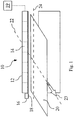
- Figure 1 shows an example of a page-wide array printing device, namely a page-wide array printer 10, which comprises a media advance system (not shown) and a print element such as a print bar 12.
- the print bar 12 comprises an array of print heads 14, for example eight print heads 14.
- the number of print heads 14 may be fewer, such as in the order of one, two, three or four print heads, or greater, such as in the order of ten, fifty, one hundred or even more.
- the print bar 12 comprises a single print head 14 that may have the same length as the print bar 12.
- the printer 10 further comprises a carriage 16 which is attached moveable to, e.g. the print bar 12, such that it can be moved along the direction of the print bar 12.
- a carriage 16 may comprise, among others, service elements, for example for performing print head servicing.
- the carriage 16 further comprises a sensor 18, e.g. an optical sensor, to scan the print medium 20.
- the media advance system advances the print medium 20 along a media axis 22 in the direction of arrow 23 ("medium-advance direction") past the print bar 12 which may print images on the print medium 20.
- the carriage 16 is moveable transversely to the media axis 22 along the direction of the print bar 12.
- the scanner is arranged such that it scans the print medium 20 while the carriage 16 moves across the print medium 20 along a scan axis 24 which is orthogonal to the media axis 22.
- the printer 10 further comprises a controller 19 which is connected to the media advance system and to the sensor 18.
- the controller 19 receives output signals from the sensor 18.
- the controller further controls the advancement of the print medium 20 by the media advance system. For example, the controller controls the advancement of the print medium 20 based on the received output signals from sensor 18.
- the printer 10 is an ink-jet printer and the each print head 14 comprises a plurality of nozzles.
- the nozzles are arranged in arrays on the print head 14.
- the arrays of nozzles are arranged on dies on the print head 14.
- Figure 2 shows an example print head 14 in two different views, a top view (left) and a bottom view (right).
- the print head 14 comprises a plurality of thermal inkjet chips, referred to as dies 36a, 36b.
- the print head 14 comprises six dies 36a, 36b.
- the number of dies 36a, 36b may be fewer, such as two or four dies 36a, 36b, or greater than six, such as eight or ten dies 36a, 36b.
- the dies 36a, 36b may be precision-aligned and placed on a dimensionally stable substrate.
- the substrate provides, e.g. mechanical alignment, printing fluid supply channels and electrical interconnection (not shown).
- the dies 36a, 36b are arranged in two rows, a row of even dies 36a and a row of odd dies 36b at the bottom of the print head 14.
- Each die 36a, 36b comprises at least one array of nozzles (not shown).
- each die 36a, 36b comprises one array of nozzles for each color.
- each die 36a, 36b may comprise four arrays of nozzles for each of four colors to be printed. The number of nozzles per array is directly related to the printing resolution measured in dots per inch ("dpi").
- the print head 14 has no moving parts.
- the print head 14 ejects drops of printing fluid through the nozzles.
- the ejection of printing fluid may be triggered by the controller 19.
- each drop has to emerge at a consistent weight, speed and direction to place a dot of correct size in the correct location.
- the distance between the print heads 14 and the print medium 20 may be controlled accurately.
- Figure 3 show an example of a media advance system 26 comprising two rollers, i.e. an idler roller 28a at an input side and a drive roller 28b at an output side.
- the print medium 20 is advanced along the medium-advance direction 23 from the input side through a print zone 32, where an example print head 14 can print images onto the print medium 20, to the output side.
- the print head 14 and, accordingly, the corresponding print bar (not shown), is fixed within the printer 10 such that the print head 14 is in a position above the print zone 32 and, thus, above the print medium 20 if present.
- the media advance system 26 may further comprise or be connected with at least one encoder 30.
- Encoders are commonly used in printers for accurately advancing the print medium 20.
- the print medium may be advanced continuously or between swaths or scans.
- the encoder 30 may be connected, for example, to the idler roller 28a at the input side.
- the encoder 30 may be connected to the drive roller 28b at the output side.
- each roller 28a, 28b may be connected to a respective encoder (not shown).
- the encoder 30 may be a digital encoder or an analog encoder 30.
- one encoder for example a digital encoder, is connected to the drive roller 28b, and another encoder, for example an analog encoder, is connected to the idler roller 28a.
- the encoder 30 is an optical encoder 30.
- the encoder 30 is a rotary encoder 30.
- the encoder 30 is a rotary optical encoder 30.
- the encoder 30 generates output signals which provide the controller with an indication of the position of the print medium 20 as the print medium 20 is advanced through the printer 10.
- the controller controls the media advance system 26 as needed to advance the print medium 20.
- a read position of the print medium 20 is indicated by output signals of an encoder 30 which are read by the controller.
- the controller controls the drive mechanism of the media advance system 26 such that the print medium 20 is advanced incrementally or continuously by the proper amount needed based on the read position of the print medium 20.
- the encoder 30 Since the encoder 30 is connected to one of the rollers 28a, 28b, the encoder output signals only indirectly indicate the actual position of the print medium 20. Moreover, the encoder 30 as well as the rollers 28a, 28b can be susceptible to runout errors. It is known that in some examples runout errors are sinusoidal varying errors that occur as a result of slight variations in the concentricity of, e.g. the rollers 28a, 28b. For example, a runout error may arise when the outer surface of a roller, e.g. a drive roller is not precisely concentric with the axis about which that roller rotates.
- At least one of the rollers 28a, 28b is driven by a power unit (not shown), such as a motor (e.g. a DC servo motor), to advance the print medium 20 through the printer 10.
- a power unit such as a motor (e.g. a DC servo motor)
- the drive roller 28b at the output side may be driven by a servo motor while the roller 28a at the input side is an idler roller.
- the media advance system further comprises a mechanism to hold down the print medium 20 in the print zone 32. In some examples, the media advance system 26 further comprises a mechanism to control the spacing between the print bar 12 and the print medium 20.
- the media advance system may be calibrated using calibration values such that the mismatch between the read position and the actual position of the print medium may be compensated, print quality may be ensured and/or the print quality issues mentioned above may be solved.
- a test pattern is printed on a calibration medium.
- the test pattern is printed on the calibration medium with the printer to be calibrated (i.e. the printer having the media advance system to be calibrated) while the calibration medium is advancing along the media axis through the printer.
- the test pattern comprises a plurality of test marks.
- the test pattern is scanned along the scan axis which is orthogonal to the media axis.
- the test pattern is scanned using the sensor in the carriage which is moveable along the scan axis.
- the test pattern may be scanned while the calibration medium advances through the printer along the media axis.
- the test pattern is printed on the calibration medium with the printer while the calibration medium advances along the media axis in the media-advance direction. After the test pattern has been printed, the calibration medium is advanced backwards along the media axis opposite to the media-advance direction. Then, the test pattern is scanned by the sensor in the carriage while the calibration medium is advanced a second time through the printer in the media-advance direction, wherein the carriage including the sensor is moved along the scan axis transversely across the calibration medium.
- the scanned signals are analyzed to determine the dimensions of the scanned test marks. For example, as a result of the analysis of the signals, the width, the length and/or the height of the test marks may be determined.
- the analyzed dimensions of the test marks are then used to determine the calibration values for the media advance system.
- Figure 4 illustrates an example test pattern 38 which is printed on a calibration medium 46 by an example print head 14.
- the print head 14 is one of a plurality of print heads 14 of a print bar 12, of which only a section is shown.
- the print head 14 comprises two rows of dies, a row of even dies 36a and a row of odd dies 36b.
- the print head 14 comprises six dies 36a, 36b, three of which for each row of dies.
- the test pattern 38 comprises a plurality of test marks 40.
- the test pattern 38 comprises two columns of test marks 40 which are aligned with the media axis 22.
- the test pattern 38 is printed to the calibration medium by the print head 14, in particular by the dies 36a, 36b of the print head 14.
- one column 42a of test marks 40 is printed to the calibration medium 46 by an even die 36a and another column 42b of test marks 40 is printed to the calibration medium 46 by an odd die 36b.
- test marks 40 are printed to the calibration medium such that a plurality of rows 44 of test marks 40 which are spaced apart from each other along the media axis 22 is formed on the calibration medium 46.
- Each row 44 of test marks 40 comprises at least two test marks 40 and is aligned with the scan axis 24.
- an offset between the triggers to eject printing fluid from the row of even dies 36a and from the row of odd dies 36b, respectively, may be taken into account to align the test marks 40 in rows
- FIG. 5 is a more detailed illustration of the test pattern 38 comprising test marks 40.
- Each test mark 40 has two portions 40a and 40b which are tapered (see also discussion below) with respect to each other along the media axis 22.
- the test marks 40 are printed to the calibration medium 46 in two columns 42a, 42b, which are aligned with the media axis 22 and located spaced-apart and adjacent to each other on the calibration medium 46.
- rows 44 of test marks 40 are formed which are spaced apart from each other along the media axis 22 and aligned with the scan axis 24, wherein each row 44 comprises one test mark 40 of each of the two columns 42a, 42b, respectively.
- the number of columns may be larger than two, such as three, four, six or eight or even more.
- the number N of rows 44 is in the order of two or three rows. In other examples the number N of rows 44 is in the order of ten, twenty or forty rows. The number N of rows 44 may also be larger than forty.
- test marks 40 have a triangular shape, for example the shape of a "V” or a reversed “V or a caret. In other examples the test marks 40 have a parabolic shape, for example the shape of a "U” or a reversed "U”. The test marks 40 may also have a semi-circular shape, such as a " " or reversed. In some examples, the test mark 40 comprises two portions 40a, 40b which are not linked to each other but positioned to each other to form a tapered test mark 40, such as a "/ ⁇ ".
- the test pattern 38 is printed on a calibration medium 46 while the calibration medium 46 is advanced through the printer 10 along the media axis in the media-advance direction by the media advance system.
- the calibration medium 46 onto which the test pattern 38 is printed is then fed into the print medium transport path of the printer 10 again, such that it can be advanced through the printer 10 along the media axis in the media-advance direction by the media advance system again.
- the position of the calibration medium 46 may be read by the encoder which is connected to the drive roller of the media advance system and signaled to the controller 19 of the printer 10.
- the calibration medium 46 including the test pattern 38 is then advanced through the print zone, above which the print bar 12 and the carriage 16 including the sensor 18 are arranged. While the calibration medium 46 advances through the print zone 32, the carriage 16 including the sensor 18 is moved across the calibration medium 46 along the scan axis row-by-row. Thus, each row 44 of test marks 40 is scanned by the scanner along the scan axis.
- the calibration medium 46 is advanced backwards along the media axis 22, i.e. opposite to the media-advance direction 23, by the media advance system after the test pattern 38 has been printed thereupon. It then starts advancing forward again to allow the sensor 18 to scan each row 44 of test marks 40.
- the sensor 18 particularly scans the dimensions of the test marks 40. For example, each time the sensor 18 detects an edge of a test mark 40, it outputs a corresponding output signal to the controller 19, indicating the position of the edge of the test mark 40 along the scan axis. Thus, based on the sensor signals the controller can analyze the dimensions of the test marks 40. The controller further receives corresponding signals from the encoder 30 which indicate the corresponding position of the calibration medium 46 along the media axis and, thus, the position of the currently detected test mark 40 on the calibration medium 46 with respect to the media axis 22.
- the sensor 18 detects a first edge of the test mark 40 when it reaches the first portion 40a of the test mark 40 and a second edge of the test mark 40 when it reaches the second portion 40b of the test mark 40 as it moves along the scan axis 24.
- the sensor 18 outputs corresponding detection signals which indicate the positions of the two edges along the scan axis to the controller 19.
- the controller 19 can determine the width X1 of the test mark 40 as the distance between the positions of the two edges of the two portions 40a, 40b along the scan axis 24. Correspondingly, the controller also determines the width X2 of the second test mark 40 in the currently scanned row of test marks 40.
- the first test mark 40 along the scan axis 24 belongs to the first column 42a of test marks, whereas the second test mark 40 along the scan axis 24 belongs to the second column 42b of test marks 40.
- the first column 42a of test marks 40 is printed on the calibration medium 46 by an even die 36a and the second column 42b of test marks 40 is printed on the calibration medium 46 by an odd die 36b of the print head 14.
- test marks 40 of each row 44 of test marks 40 will be perfect and the difference X1-X2 of the widths X1 and X2 of the two test marks 40 will be constant along the rows 44, assuming the two test marks 40 to be identical.
- the test marks 40 will be misaligned and the widths X1 and X2 will differ. Therefore, calculating the differences X1-X2 of the widths X1, X2 for each pair of test marks 40 allows calibration values which indicate the magnitude of the die to die advance error to be determined.
- Print quality issues related to media advance performance limitations may appear mainly due to the mismatch between the read and the actual position of the print medium.
- One of its main contributors may be the runout of the roller with which the encoder 30 is connected.
- Another contributor may be the eccentricity of the encoder 30 with respect to the roller revolution axis.
- the runout of, e.g. the drive roller and the eccentricity of the encoder 30 cause a periodically variable, in particular sinusoidal, mismatch between the read and the actual position of the print medium.
- the period of its frequency corresponds to one revolution of the roller with which the encoder 30 is connected.
- both rows of dies 36a, 36b may see the print medium 20 speed in different phases due to the distance between the rows 36a, 36b.
- one revolution of, e.g. a drive roller may be about 212 mm and the distance between the row of even dies 36a and the row of odd dies 36b may be about 18 mm. That is, the rows of dies 36a, 36b are in approximately 30 degrees of the frequency with respect to the drive roller revolution. In other words, the odd row of dies 36b may see the print medium 20 with a delay of 30 degrees compared to the even row of dies 36a.
- the trigger for ejecting printing fluid onto the print medium 20 considers an offset or distance between both rows of dies 36a, 36b, but it only contemplates a constant delay, not a variable delay.
- the sinusoidal signal of the encoder 30 is causing a variable delay which changes along a plot with a frequency of one revolution of the roller with which the encoder 30 is connected. Consequently, the trigger for ejecting printing fluid onto the print medium 20 is generated with an error which is variable along the media axis.
- Figure 6 shows the position error variation of the print medium in mm and the delay of 30 degrees between the rows of even and odd dies 37a, 37b. It further shows the variable error 39 resulting from this variable delay, as explained above.
- the period of its frequency which corresponds to one revolution of the roller 28a is indicated by arrow 34.
- the variable error causes print quality issues that can be noticed by the user.
- the test pattern 38 as shown in Figure 6 comprises different sections, i.e. columns of test marks 40, each of which is printed by a different row of dies, even and odd 36a, 36b.
- the print quality issue then appears as a variable misalignment between the two columns 42a, 42b of test marks 40.
- the variable misalignment can be compensated with a corresponding calibration using the determined calibration values.
- the calibration values can be used to compensate a sinusoidal error.
- the calibration values are determined by calculating the differences X1-X2 of the widths XI, X2 of the test marks 40 for each row 44 of test marks 40. Due to the variable mismatch between the read and the actual position of the calibration medium 46, these differences X1-X2 are generally non-zero and variable, in particular sinusoidal.
- Figure 7 shows a plot of these differences X1-X2 with respect to the advancing position of the calibration medium 46 in mm as read by the encoder 30.
- the sensor 18 scans each row 44 of test marks 40 and, thus, the difference X1-X2 is calculated for each row 44.
- the rows 44 of test marks 40 have been printed on the calibration medium 46 which, in turn, has been advanced through the print zone 32 row-by-row, i.e. each time a row 44 of test marks 40 has been printed on the calibration medium 46, the calibration medium 46 has been advanced by an amount corresponding to the distance between two adjacent rows 44.
- the controller 19 which is connected to both the encoder 30 and the sensor 18 thus knows the number N of the row 44 for which the test pattern 38 is currently printed (during the test pattern printing step) and for which the test pattern 38 is scanned (during the scanning step). The controller further knows the position of this current row 44, i.e. the N -th row, on the calibration medium 46 as read by the encoder 30.
- a sinusoidal function 48 is fitted to these data points and its amplitude A and phase ⁇ are calculated.
- the fitting can be done with different methods depending on the selected curve fit algorithm.
- the function 48 may also be determined by any known way of interpolation, extrapolation, regression analysis or the like.
- Each data point represents the misalignment in one particular row 44 of test marks 40.
- To calculate the phase ⁇ properly it may be important to know the position of the plot related to a zero/index of the encoder 30. The zero/index may be the reference to apply the calibration parameters during the normal printing operation. Based on these calibration values, i.e. the amplitude A and phase ⁇ of the sinusoidal fit function, the media advance system 26 may be calibrated.
- all test marks 40 of all N rows 44 may be identical.
- the calibration values may be used to determine for each printing line to be printed during a normal printing process a compensation value for which the misalignment as calculated on the basis of the calibration values and the sinusoidal fit function may be compensated.
- the term printing line may refer to the line which results from the printing resolution of the printer 10 in direction of the media axis 22.
- the misalignment is determined for each row 44 of test marks 40.
- Each test mark 40 may encompass a number of test mark printing lines.
- the number of rows 44 may be lower than the number of printing lines by the factor of the number of test mark printing lines.
- the number of test mark printing lines is twice as much as the value (in terms of printing lines) of the maximum expected misalignment.
- the difference X1-X2 is scanned and calculated for more than one test mark printing line, e.g. for each printing line, and then an averaged misalignment value is determined for each row 44 on the basis of the misalignment values calculated for each scanned test mark printing line of test mark 40 of that row 44.
- a sinusoidal function is fitted to the differences X1-X2 as scanned and calculated for each printing line.
- test mark printing lines it is again referred to the term tapered test mark which will now be further explained on the basis of the above term test mark printing lines.
- a tapered test mark may result if, for instance, the width of the test mark monotonously increases or decreases as a function of the test mark printing line. In other words, if the test mark has a given width in its topmost test mark printing line then its width monotonously increases or decreases for every subjacent test mark printing line.
- the calibration values A and ⁇ may be stored in a memory such that they can be applied to the media advance system 26 repeatedly during each printing process.
- the memory may be an internal memory of the printer 10 and/or the controller 19.
- the memory may also be an external memory to which the printer 10 and/or the controller 19 is connected.
- Figure 8 illustrates an example method for determining calibration values of a media advance system of a page-wide array printing device.
- the example method includes, in block 50, printing the test pattern 38 comprising a plurality of test marks 40 onto the calibration medium 46.
- the calibration medium 46 advances along a media axis through the printer 10.
- the calibration medium 46 may be any kind of sheet-like medium, such as paper, cardboard, plastic or textile.
- the calibration medium 46 may be of the same kind as the print medium 20.
- the example method further includes, in block 52, scanning the test pattern along a scan axis 24 which is orthogonal to the media axis 22.
- the test pattern 38 is scanned using a sensor 18.
- the sensor 18 scans the test marks 40 along the scan axis 24.
- the sensor 18 may detect the edges of the test marks 40 along the scan axis 24.
- the calibration medium 46 is advanced along the media axis through the printer 10.
- the scanned test pattern 38 is analyzed.
- the dimensions of the scanned test marks 40 are analyzed.
- the sensor 18 may output signals to the controller 19 which indicate the detection of edges of the test marks 40.
- the sensor 18 may detect the edge of a first and a second portion 40a, 40b of each test mark 40.
- the controller 19 determines, based on these signals, the widths XI, X2 of the test marks 40 as distances between the two portions 40a, 40b of each test mark 40 along the scan axis 24.
- Analyzing the test pattern further includes determining the differences of the widths X1, X2 of the test marks 40 of one row 44 of test marks 40.
- the example method may further include, in block 56, fitting a periodic function to the determined differences of the widths XI, X2 of the test marks 40 with respect to the corresponding row 44 of test marks 40.
- the periodic function may be a sinusoidal function.
- the calibration values are determined based on the analyzed dimensions of the test marks 40.
- the calibration values may be determined based on the analyzed widths XI, X2 of the test marks 40. More particularly, the calibration values may be determined based on the determined differences of the widths XI, X2 of the test marks 40.
- the calibration values may be determined based on the periodic, e.g. sinusoidal function which may be fitted to the determined differences of the widths XI, X2 of the test marks 40 with respect to the corresponding row 44 of test marks 40 in block 56.
- the calibration values may be based on the fit parameters, such as the amplitude A and the phase ⁇ of the fit function.
- the example method may further include, in block 60, storing the calibration values to a memory.
- the memory may be an internal memory of the printer 10.
- the memory may also be an external memory which is connected to the printer 10 and/or the controller 19.
- the example method may be performed by a processor, for example a computer processor, which has been instructed accordingly.
- the instructions for the processor may be stored on a medium, particularly on a computer readable medium.
- the computer readable medium may be a non-transitory computer readable medium.
- the instructions may be stored on the medium in the form of a program.
Landscapes
- Engineering & Computer Science (AREA)
- Health & Medical Sciences (AREA)
- Biomedical Technology (AREA)
- General Health & Medical Sciences (AREA)
- Multimedia (AREA)
- Signal Processing (AREA)
- Accessory Devices And Overall Control Thereof (AREA)
- Ink Jet (AREA)
- Handling Of Sheets (AREA)
Description
- The description is related to printing devices, like page-wide array printing devices, having a media advance system. It further refers to calibrating a media advance system of a page-wide array printing device.
-
EP1764996 A1 discloses a method and apparatus for aligning the printing of dots generated by one or more arrays of printing elements wherein a calibration test pattern is printed, a camera is positioned relative to the printed calibration test pattern and a detail of the calibration test pattern is imaged and processed, and wherein the alignment of the one or more arrays of printing elements is adjusted on the basis of a calibration value derived from processing the imaged calibration test pattern. -
US2011311290 A1 discloses calibrating a media drive, comprising advancing media with a media drive while detecting media advances within the printer, determining an error in the media advances, and calibrating the media drive so as to at least partly compensate for the determined error. - Examples will be described, by way of example only, with reference to the accompanying drawings in which corresponding reference numerals indicate corresponding parts and in which:
-
Figure 1 is a schematic view of an example printing device; -
Figure 2 shows two different views of an example print head; -
Figure 3 is a schematic view of an example media advance system; -
Figure 4 is a schematic view of an example test pattern which is printed onto the print medium by an example print head; -
Figure 5 is a more detailed view of the example test pattern; -
Figure 6 shows an example sinusoidal error of the printer; and -
Figure 7 shows an example fit of a sinusoidal function to the errors. -
Figure 8 is a block diagram illustrating the method for determining calibration values. - In general, a page-wide array printing device comprises a print medium transport path and a print element, such as a print head or a print bar comprising an array of print heads, extending the full width of the print medium transport path. Such an arrangement allows the entire width of a print medium to be printed simultaneously. A printing device refers generally to devices which can produce printed output, including but not limited to, for example, a printer, a photocopier, a fax machine, etc.
- A print medium may be any kind of sheet-like medium, such as paper, cardboard, plastic or textile. The print element may be fixed within the printing device, and a print medium may be advanced past the print element along the print medium transport path by a media advance system. During a printing process, the print medium is advanced in the direction of a media axis ("medium-advance direction") through a print zone where an image or images are printed on the print medium by the print element. In some examples, the image may be printed on the print medium in rows or swaths. In other examples, the image may be printed continuously while the print medium is advancing below the print element. Images refers to any kind of depiction of signs, symbols, numbers, letters, text and/or graphics which may be applied to the print medium. In some examples, the height of the printed swaths (as measured in the medium-advance direction) may be fixed for a particular print element.
- Media advance systems may include, e.g. motors, gears, rollers, sensors, and other components which work in conjunction to advance the print medium incrementally or continuously. Due to, e.g. geometric deviation in the hardware used to advance the print medium or the hardware used to read the advancement of the print medium, mismatches between the expected or read position of the print medium and its actual position can occur. For example, one component in a media advance system is a media drive roller. A deviation of the drive roller diameter from its ideal diameter or a deviation of its circumferential shape from the ideal circular shape can lead to runout (feedrate) errors, causing the print medium to be, e.g. underfed and to substantially sinusoidal "once-per-revolution" errors of the printing device. These errors cause different print quality issues with different severities. For example, a misalignment between the sections printed in one row or swath, or continuously in at least one printing line, by the print element may appear on the print medium. Here, the term printing line may refer to the line which results from the printing resolution of the printing device in direction of the media axis. To compensate for these errors and, thus, to ensure print quality, the media advance system has to be calibrated accordingly.
-
Figure 1 shows an example of a page-wide array printing device, namely a page-wide array printer 10, which comprises a media advance system (not shown) and a print element such as aprint bar 12. Theprint bar 12 comprises an array ofprint heads 14, for example eightprint heads 14. The number ofprint heads 14 may be fewer, such as in the order of one, two, three or four print heads, or greater, such as in the order of ten, fifty, one hundred or even more. In some examples, theprint bar 12 comprises asingle print head 14 that may have the same length as theprint bar 12. - The
printer 10 further comprises acarriage 16 which is attached moveable to, e.g. theprint bar 12, such that it can be moved along the direction of theprint bar 12. Such acarriage 16 may comprise, among others, service elements, for example for performing print head servicing. Thecarriage 16 further comprises asensor 18, e.g. an optical sensor, to scan theprint medium 20. - The media advance system advances the
print medium 20 along amedia axis 22 in the direction of arrow 23 ("medium-advance direction") past theprint bar 12 which may print images on theprint medium 20. Thecarriage 16 is moveable transversely to themedia axis 22 along the direction of theprint bar 12. The scanner is arranged such that it scans theprint medium 20 while thecarriage 16 moves across theprint medium 20 along ascan axis 24 which is orthogonal to themedia axis 22. - The
printer 10 further comprises acontroller 19 which is connected to the media advance system and to thesensor 18. Thecontroller 19 receives output signals from thesensor 18. The controller further controls the advancement of theprint medium 20 by the media advance system. For example, the controller controls the advancement of theprint medium 20 based on the received output signals fromsensor 18. - In some examples, the
printer 10 is an ink-jet printer and the eachprint head 14 comprises a plurality of nozzles. In some examples, the nozzles are arranged in arrays on theprint head 14. In some examples, the arrays of nozzles are arranged on dies on theprint head 14. -
Figure 2 shows anexample print head 14 in two different views, a top view (left) and a bottom view (right). Theprint head 14 comprises a plurality of thermal inkjet chips, referred to asdies print head 14 comprises sixdies dies dies dies dies - The
dies odd dies 36b at the bottom of theprint head 14. Each die 36a, 36b comprises at least one array of nozzles (not shown). In some examples, eachdie die die - The
print head 14 has no moving parts. Theprint head 14 ejects drops of printing fluid through the nozzles. The ejection of printing fluid may be triggered by thecontroller 19. In some examples, each drop has to emerge at a consistent weight, speed and direction to place a dot of correct size in the correct location. Also the distance between the print heads 14 and theprint medium 20 may be controlled accurately. -
Figure 3 show an example of amedia advance system 26 comprising two rollers, i.e. anidler roller 28a at an input side and adrive roller 28b at an output side. Theprint medium 20 is advanced along the medium-advance direction 23 from the input side through aprint zone 32, where anexample print head 14 can print images onto theprint medium 20, to the output side. Theprint head 14 and, accordingly, the corresponding print bar (not shown), is fixed within theprinter 10 such that theprint head 14 is in a position above theprint zone 32 and, thus, above theprint medium 20 if present. - The
media advance system 26 may further comprise or be connected with at least oneencoder 30. Encoders are commonly used in printers for accurately advancing theprint medium 20. The print medium may be advanced continuously or between swaths or scans. Theencoder 30 may be connected, for example, to theidler roller 28a at the input side. In other examples, theencoder 30 may be connected to thedrive roller 28b at the output side. In further examples, eachroller encoder 30 may be a digital encoder or ananalog encoder 30. In some examples, one encoder, for example a digital encoder, is connected to thedrive roller 28b, and another encoder, for example an analog encoder, is connected to theidler roller 28a. In some examples, theencoder 30 is anoptical encoder 30. In some examples, theencoder 30 is arotary encoder 30. In some examples, theencoder 30 is a rotaryoptical encoder 30. - The
encoder 30 generates output signals which provide the controller with an indication of the position of theprint medium 20 as theprint medium 20 is advanced through theprinter 10. The controller, in turn, controls themedia advance system 26 as needed to advance theprint medium 20. - For example, when the
print medium 20 is advanced through theprint zone 32 by themedia advance system 26, an image can be printed to theprint medium 20 by the print heads 14 of theprint bar 12 in rows or swaths or continuously while theprint medium 20 is advancing below the print heads 14. To ensure that the swath to be printed or the printing line to be printed is accurately aligned with the previous swath or printing line, respectively, a read position of theprint medium 20 is indicated by output signals of anencoder 30 which are read by the controller. The controller controls the drive mechanism of themedia advance system 26 such that theprint medium 20 is advanced incrementally or continuously by the proper amount needed based on the read position of theprint medium 20. - Since the
encoder 30 is connected to one of therollers print medium 20. Moreover, theencoder 30 as well as therollers rollers - As a result of runout errors, the magnitude of the position changes of the print medium as indicated by the encoder output signals will not precisely match the actual position change of the print medium. Thus, a mismatch between the read position of the print medium and its actual position occurs.
- In some examples, at least one of the
rollers print medium 20 through theprinter 10. For example, thedrive roller 28b at the output side may be driven by a servo motor while theroller 28a at the input side is an idler roller. - In some examples, the media advance system further comprises a mechanism to hold down the
print medium 20 in theprint zone 32. In some examples, themedia advance system 26 further comprises a mechanism to control the spacing between theprint bar 12 and theprint medium 20. - However, mismatches between the read position and the actual position of the print medium can lead to print quality issues, such as defects or irregularities in the printed image. For example, dot placement errors or lack of fidelity in reproduction of colors may occur. Thus, the media advance system may be calibrated using calibration values such that the mismatch between the read position and the actual position of the print medium may be compensated, print quality may be ensured and/or the print quality issues mentioned above may be solved.
- To determine the calibration values for the media advance system, first a test pattern is printed on a calibration medium. In some examples, the test pattern is printed on the calibration medium with the printer to be calibrated (i.e. the printer having the media advance system to be calibrated) while the calibration medium is advancing along the media axis through the printer. The test pattern comprises a plurality of test marks.
- Then the test pattern is scanned along the scan axis which is orthogonal to the media axis. In some examples, the test pattern is scanned using the sensor in the carriage which is moveable along the scan axis. The test pattern may be scanned while the calibration medium advances through the printer along the media axis. In some examples, the test pattern is printed on the calibration medium with the printer while the calibration medium advances along the media axis in the media-advance direction. After the test pattern has been printed, the calibration medium is advanced backwards along the media axis opposite to the media-advance direction. Then, the test pattern is scanned by the sensor in the carriage while the calibration medium is advanced a second time through the printer in the media-advance direction, wherein the carriage including the sensor is moved along the scan axis transversely across the calibration medium.
- The scanned signals are analyzed to determine the dimensions of the scanned test marks. For example, as a result of the analysis of the signals, the width, the length and/or the height of the test marks may be determined.
- The analyzed dimensions of the test marks are then used to determine the calibration values for the media advance system.
-
Figure 4 illustrates anexample test pattern 38 which is printed on acalibration medium 46 by anexample print head 14. Theprint head 14 is one of a plurality of print heads 14 of aprint bar 12, of which only a section is shown. Theprint head 14 comprises two rows of dies, a row of even dies 36a and a row of odd dies 36b. For example, theprint head 14 comprises six dies 36a, 36b, three of which for each row of dies. - The
test pattern 38 comprises a plurality of test marks 40. For example, thetest pattern 38 comprises two columns of test marks 40 which are aligned with themedia axis 22. Thetest pattern 38 is printed to the calibration medium by theprint head 14, in particular by the dies 36a, 36b of theprint head 14. For example, onecolumn 42a of test marks 40 is printed to thecalibration medium 46 by an even die 36a and anothercolumn 42b of test marks 40 is printed to thecalibration medium 46 by anodd die 36b. - The columns of test marks 40 are printed to the calibration medium such that a plurality of
rows 44 of test marks 40 which are spaced apart from each other along themedia axis 22 is formed on thecalibration medium 46. Eachrow 44 of test marks 40 comprises at least twotest marks 40 and is aligned with thescan axis 24. - As the
calibration medium 46 advances along themedia axis 22 in the media-advance direction 23, it will reach a position below the row of even dies 36a before it reaches a position below the row of odd dies 36b. Thus, an offset between the triggers to eject printing fluid from the row of even dies 36a and from the row of odd dies 36b, respectively, may be taken into account to align the test marks 40 in rows -
Figure 5 is a more detailed illustration of thetest pattern 38 comprising test marks 40. Eachtest mark 40 has twoportions media axis 22. The test marks 40 are printed to thecalibration medium 46 in twocolumns media axis 22 and located spaced-apart and adjacent to each other on thecalibration medium 46. Thus,rows 44 of test marks 40 are formed which are spaced apart from each other along themedia axis 22 and aligned with thescan axis 24, wherein eachrow 44 comprises onetest mark 40 of each of the twocolumns - In some examples, two
columns calibration medium 46. Thus,N rows 44 having twotest marks 40 each, one for each of the twocolumns N rows 44 are aligned with thescan axis 24 and wherein theN rows 44 are spaced apart along themedia axis 22. In some examples, the number of columns may be larger than two, such as three, four, six or eight or even more. In some examples, the number N ofrows 44 is in the order of two or three rows. In other examples the number N ofrows 44 is in the order of ten, twenty or forty rows. The number N ofrows 44 may also be larger than forty. - In some examples the test marks 40 have a triangular shape, for example the shape of a "V" or a reversed "V or a caret. In other examples the test marks 40 have a parabolic shape, for example the shape of a "U" or a reversed "U". The test marks 40 may also have a semi-circular shape, such as a "" or reversed. In some examples, the

test mark 40 comprises twoportions test mark 40, such as a "/ \". - In the following, the method for determining calibration values for the media advance system using the
calibration medium 46 onto which thetest pattern 38 is printed will be described in more detail. - As an initial step, the
test pattern 38 is printed on acalibration medium 46 while thecalibration medium 46 is advanced through theprinter 10 along the media axis in the media-advance direction by the media advance system. Thecalibration medium 46 onto which thetest pattern 38 is printed is then fed into the print medium transport path of theprinter 10 again, such that it can be advanced through theprinter 10 along the media axis in the media-advance direction by the media advance system again. The position of thecalibration medium 46 may be read by the encoder which is connected to the drive roller of the media advance system and signaled to thecontroller 19 of theprinter 10. - The
calibration medium 46 including thetest pattern 38 is then advanced through the print zone, above which theprint bar 12 and thecarriage 16 including thesensor 18 are arranged. While thecalibration medium 46 advances through theprint zone 32, thecarriage 16 including thesensor 18 is moved across thecalibration medium 46 along the scan axis row-by-row. Thus, eachrow 44 of test marks 40 is scanned by the scanner along the scan axis. - In some examples, the
calibration medium 46 is advanced backwards along themedia axis 22, i.e. opposite to the media-advance direction 23, by the media advance system after thetest pattern 38 has been printed thereupon. It then starts advancing forward again to allow thesensor 18 to scan eachrow 44 of test marks 40. - The
sensor 18 particularly scans the dimensions of the test marks 40. For example, each time thesensor 18 detects an edge of atest mark 40, it outputs a corresponding output signal to thecontroller 19, indicating the position of the edge of thetest mark 40 along the scan axis. Thus, based on the sensor signals the controller can analyze the dimensions of the test marks 40. The controller further receives corresponding signals from theencoder 30 which indicate the corresponding position of thecalibration medium 46 along the media axis and, thus, the position of the currently detectedtest mark 40 on thecalibration medium 46 with respect to themedia axis 22. - For example, in the case of a
test pattern 38 as shown inFigure 5 , i.e. comprisingN rows 44 of twotest marks 40 along the scan axis, respectively, the test marks 40 having the shape of an inverted "V", thesensor 18 detects a first edge of thetest mark 40 when it reaches thefirst portion 40a of thetest mark 40 and a second edge of thetest mark 40 when it reaches thesecond portion 40b of thetest mark 40 as it moves along thescan axis 24. Thesensor 18 outputs corresponding detection signals which indicate the positions of the two edges along the scan axis to thecontroller 19. By analyzing these signals thecontroller 19 can determine the width X1 of thetest mark 40 as the distance between the positions of the two edges of the twoportions scan axis 24. Correspondingly, the controller also determines the width X2 of thesecond test mark 40 in the currently scanned row of test marks 40. - The
first test mark 40 along thescan axis 24 belongs to thefirst column 42a of test marks, whereas thesecond test mark 40 along thescan axis 24 belongs to thesecond column 42b of test marks 40. As already explained, thefirst column 42a of test marks 40 is printed on thecalibration medium 46 by an even die 36a and thesecond column 42b of test marks 40 is printed on thecalibration medium 46 by anodd die 36b of theprint head 14. There is a constant offset between the row of even dies 36a and the row of odd dies 36b. Thus, to ensure that the test marks 40 of eachrow 44 are aligned along thescan axis 24, there is a constant delay between triggering the ejection of printing fluid by the even die 36a and theodd die 36b. - If there are no mismatches between the read position of the
print medium 20 and its actual position, the alignment of the test marks 40 of eachrow 44 of test marks 40 will be perfect and the difference X1-X2 of the widths X1 and X2 of the twotest marks 40 will be constant along therows 44, assuming the twotest marks 40 to be identical. However, if there is a mismatch between the read position and the actual position of theprint medium 20, the test marks 40 will be misaligned and the widths X1 and X2 will differ. Therefore, calculating the differences X1-X2 of the widths X1, X2 for each pair of test marks 40 allows calibration values which indicate the magnitude of the die to die advance error to be determined. - Print quality issues related to media advance performance limitations may appear mainly due to the mismatch between the read and the actual position of the print medium. One of its main contributors may be the runout of the roller with which the
encoder 30 is connected. Another contributor may be the eccentricity of theencoder 30 with respect to the roller revolution axis. - The runout of, e.g. the drive roller and the eccentricity of the
encoder 30 cause a periodically variable, in particular sinusoidal, mismatch between the read and the actual position of the print medium. The period of its frequency corresponds to one revolution of the roller with which theencoder 30 is connected. Without any calibration or compensation, both rows of dies 36a, 36b may see theprint medium 20 speed in different phases due to the distance between therows print medium 20 with a delay of 30 degrees compared to the even row of dies 36a. - The trigger for ejecting printing fluid onto the
print medium 20 considers an offset or distance between both rows of dies 36a, 36b, but it only contemplates a constant delay, not a variable delay. However, the sinusoidal signal of theencoder 30 is causing a variable delay which changes along a plot with a frequency of one revolution of the roller with which theencoder 30 is connected. Consequently, the trigger for ejecting printing fluid onto theprint medium 20 is generated with an error which is variable along the media axis. -
Figure 6 shows the position error variation of the print medium in mm and the delay of 30 degrees between the rows of even and odd dies 37a, 37b. It further shows thevariable error 39 resulting from this variable delay, as explained above. The period of its frequency which corresponds to one revolution of theroller 28a is indicated byarrow 34. The variable error causes print quality issues that can be noticed by the user. - For example, the
test pattern 38 as shown inFigure 6 comprises different sections, i.e. columns of test marks 40, each of which is printed by a different row of dies, even and odd 36a, 36b. The print quality issue then appears as a variable misalignment between the twocolumns - As mentioned above, the calibration values are determined by calculating the differences X1-X2 of the widths XI, X2 of the test marks 40 for each
row 44 of test marks 40. Due to the variable mismatch between the read and the actual position of thecalibration medium 46, these differences X1-X2 are generally non-zero and variable, in particular sinusoidal. -
Figure 7 shows a plot of these differences X1-X2 with respect to the advancing position of thecalibration medium 46 in mm as read by theencoder 30. As explained above, thesensor 18 scans eachrow 44 of test marks 40 and, thus, the difference X1-X2 is calculated for eachrow 44. Therows 44 of test marks 40 have been printed on thecalibration medium 46 which, in turn, has been advanced through theprint zone 32 row-by-row, i.e. each time arow 44 of test marks 40 has been printed on thecalibration medium 46, thecalibration medium 46 has been advanced by an amount corresponding to the distance between twoadjacent rows 44. Thecontroller 19 which is connected to both theencoder 30 and thesensor 18 thus knows the number N of therow 44 for which thetest pattern 38 is currently printed (during the test pattern printing step) and for which thetest pattern 38 is scanned (during the scanning step). The controller further knows the position of thiscurrent row 44, i.e. the N-th row, on thecalibration medium 46 as read by theencoder 30. - A
sinusoidal function 48 is fitted to these data points and its amplitude A and phase θ are calculated. The fitting can be done with different methods depending on the selected curve fit algorithm. Thefunction 48 may also be determined by any known way of interpolation, extrapolation, regression analysis or the like. Each data point represents the misalignment in oneparticular row 44 of test marks 40. To calculate the phase θ properly, it may be important to know the position of the plot related to a zero/index of theencoder 30. The zero/index may be the reference to apply the calibration parameters during the normal printing operation. Based on these calibration values, i.e. the amplitude A and phase θ of the sinusoidal fit function, themedia advance system 26 may be calibrated. To facilitate the fitting of a sinusoidal function to the data points and the evaluation of the fit function, all test marks 40 of allN rows 44 may be identical. - Thus, the calibration values may be used to determine for each printing line to be printed during a normal printing process a compensation value for which the misalignment as calculated on the basis of the calibration values and the sinusoidal fit function may be compensated. Here, the term printing line may refer to the line which results from the printing resolution of the
printer 10 in direction of themedia axis 22. During the calibration process, the misalignment is determined for eachrow 44 of test marks 40. Eachtest mark 40 may encompass a number of test mark printing lines. Thus, the number ofrows 44 may be lower than the number of printing lines by the factor of the number of test mark printing lines. In some examples, the number of test mark printing lines is twice as much as the value (in terms of printing lines) of the maximum expected misalignment. In some examples, the difference X1-X2 is scanned and calculated for more than one test mark printing line, e.g. for each printing line, and then an averaged misalignment value is determined for eachrow 44 on the basis of the misalignment values calculated for each scanned test mark printing line oftest mark 40 of thatrow 44. In some examples, a sinusoidal function is fitted to the differences X1-X2 as scanned and calculated for each printing line. - It is again referred to the term tapered test mark which will now be further explained on the basis of the above term test mark printing lines. As a test mark may encompass a number of test mark printing lines, a tapered test mark may result if, for instance, the width of the test mark monotonously increases or decreases as a function of the test mark printing line. In other words, if the test mark has a given width in its topmost test mark printing line then its width monotonously increases or decreases for every subjacent test mark printing line.
- The calibration values A and θ may be stored in a memory such that they can be applied to the
media advance system 26 repeatedly during each printing process. The memory may be an internal memory of theprinter 10 and/or thecontroller 19. The memory may also be an external memory to which theprinter 10 and/or thecontroller 19 is connected. - Now referring to
Figure 8 which illustrates an example method for determining calibration values of a media advance system of a page-wide array printing device. - The example method includes, in
block 50, printing thetest pattern 38 comprising a plurality of test marks 40 onto thecalibration medium 46. Thecalibration medium 46 advances along a media axis through theprinter 10. Thecalibration medium 46 may be any kind of sheet-like medium, such as paper, cardboard, plastic or textile. In particular, thecalibration medium 46 may be of the same kind as theprint medium 20. - The example method further includes, in
block 52, scanning the test pattern along ascan axis 24 which is orthogonal to themedia axis 22. Thetest pattern 38 is scanned using asensor 18. In particular, thesensor 18 scans the test marks 40 along thescan axis 24. For example, thesensor 18 may detect the edges of the test marks 40 along thescan axis 24. Thecalibration medium 46 is advanced along the media axis through theprinter 10. - In
block 54, the scannedtest pattern 38 is analyzed. In particular, the dimensions of the scanned test marks 40 are analyzed. For example, thesensor 18 may output signals to thecontroller 19 which indicate the detection of edges of the test marks 40. In particular, thesensor 18 may detect the edge of a first and asecond portion test mark 40. Thecontroller 19 determines, based on these signals, the widths XI, X2 of the test marks 40 as distances between the twoportions test mark 40 along thescan axis 24. - Analyzing the test pattern further includes determining the differences of the widths X1, X2 of the test marks 40 of one
row 44 of test marks 40. - The example method may further include, in
block 56, fitting a periodic function to the determined differences of the widths XI, X2 of the test marks 40 with respect to the correspondingrow 44 of test marks 40. In particular, the periodic function may be a sinusoidal function. - In
block 58, the calibration values are determined based on the analyzed dimensions of the test marks 40. In particular, the calibration values may be determined based on the analyzed widths XI, X2 of the test marks 40. More particularly, the calibration values may be determined based on the determined differences of the widths XI, X2 of the test marks 40. For example, the calibration values may be determined based on the periodic, e.g. sinusoidal function which may be fitted to the determined differences of the widths XI, X2 of the test marks 40 with respect to the correspondingrow 44 of test marks 40 inblock 56. For example, the calibration values may be based on the fit parameters, such as the amplitude A and the phase θ of the fit function. - The example method may further include, in
block 60, storing the calibration values to a memory. The memory may be an internal memory of theprinter 10. The memory may also be an external memory which is connected to theprinter 10 and/or thecontroller 19. - The example method may be performed by a processor, for example a computer processor, which has been instructed accordingly. The instructions for the processor may be stored on a medium, particularly on a computer readable medium. The computer readable medium may be a non-transitory computer readable medium. The instructions may be stored on the medium in the form of a program.
Claims (13)
- A method of determining calibration values for a media advance system of a page wide array printing device comprising:printing (50) a test pattern comprising a plurality of test marks on a calibration medium which advances along a media axis through the printing device,scanning (52) the test pattern along a scan axis using a sensor and advancing the calibration medium along the media axis through the printing device, wherein the scan axis is orthogonal to the media axis, the sensor configured to output signals which indicate the detection of edges of the test marks;analyzing (54), based on the signals from the sensor, the dimensions of the scanned test marks, wherein analysing the dimensions of the scanned test marks includes determining the widths of at least two test marks along the scan axis, anddetermining (58) calibration values from the analyzed dimensions of the test marks, wherein determining the calibration values includes determining the difference of the widths of the at least two test marks.
- The method according to claim 1, wherein the page wide array printing device comprises at least one print head having at least two different rows of dies and wherein printing the test pattern on the calibration medium comprises printing at least two columns of test marks on the calibration medium, said columns being aligned with the media axis, wherein at least one die of each of the different rows of dies prints at least one column of test marks on the calibration medium.
- The method according to claim 2, wherein the at least two columns of test marks are printed on the calibration medium such that a plurality of rows of test marks is formed on the calibration medium, said rows being spaced apart from each other along the media axis, and wherein each row comprises at least two test marks of different columns of test marks and wherein each row is aligned with the scan axis.
- The method according to claim 1, wherein the test marks each have two portions which are tapered with respect to each other along the media axis.
- The method according to claim 4,
wherein the width of a test mark is the distance between the two portions of the test mark along the scan axis. - The method according to claim 1, wherein determining the calibration values further includes fitting a periodic function to the determined differences of the widths of the at least two test marks with respect to the corresponding row of test marks.
- The method according to claim 6, wherein the periodic function is a sinusoidal function.
- A page wide array printing device comprising:a media advance system,a print element,a sensor, anda controller,wherein the page wide array printing device is to determine calibration values for a media advance system byprinting (50) a test pattern comprising a plurality of test marks on a calibration medium which advances along a media axis through the printing device, wherein the scan axis is orthogonal to the media axis,scanning (52) the test pattern along a scan axis using the sensor and advancing the calibration medium along the media axis through the printing device, the sensor configured to output signals to the controller which indicate the detection of edges of the test marks;analyzing (54), based on the signals from the sensor, the dimensions of the scanned test marks, wherein analysing the dimensions of the scanned test marks includes determining the widths of at least two test marks along the scan axis, anddetermining (58) calibration values from the analyzed dimensions of the test marks, wherein determining the calibration values includes determining the difference of the widths of the at least two test marks.
- The printing device according to claim 8, wherein the media advance system comprises at least one roller and at least one encoder which is connected to the at least one roller.
- The printing device according to claim 8, wherein the print element is one of a print head and a print bar.
- The printing device according to claim 10, wherein the print element is a print bar comprising a plurality of print heads.
- The printing device according to claim 11, wherein each print head comprises two rows of dies.
- A non-transitory computer readable medium for storing a program causing a processor to perform a method according to any of claims 1-7.
Applications Claiming Priority (1)
| Application Number | Priority Date | Filing Date | Title |
|---|---|---|---|
| PCT/EP2015/002174 WO2017071724A1 (en) | 2015-10-30 | 2015-10-30 | Calibrating a media advance system of a page wide array printing device |
Publications (2)
| Publication Number | Publication Date |
|---|---|
| EP3317110A1 EP3317110A1 (en) | 2018-05-09 |
| EP3317110B1 true EP3317110B1 (en) | 2021-04-07 |
Family
ID=54366179
Family Applications (1)
| Application Number | Title | Priority Date | Filing Date |
|---|---|---|---|
| EP15788330.7A Active EP3317110B1 (en) | 2015-10-30 | 2015-10-30 | Calibrating a media advance system of a page wide array printing device |
Country Status (4)
| Country | Link |
|---|---|
| US (1) | US10440195B2 (en) |
| EP (1) | EP3317110B1 (en) |
| CN (1) | CN108349273B (en) |
| WO (1) | WO2017071724A1 (en) |
Families Citing this family (6)
| Publication number | Priority date | Publication date | Assignee | Title |
|---|---|---|---|---|
| US10857808B2 (en) * | 2017-02-07 | 2020-12-08 | Hewlett-Packard Development Company, L.P. | Calibrating printing pens of print head assemblies |
| JP7182940B2 (en) * | 2018-08-01 | 2022-12-05 | キヤノン株式会社 | Recording device and recording method |
| WO2021066830A1 (en) | 2019-10-03 | 2021-04-08 | Hewlett-Packard Development Company, L.P. | Calibration of printing devices |
| EP4210959A1 (en) * | 2020-09-07 | 2023-07-19 | Hewlett-Packard Development Company, L.P. | Determining the size of a print media |
| CN112140730B (en) * | 2020-09-23 | 2021-06-25 | 深圳市汉森软件有限公司 | Method, device and equipment for adjusting driving waveform of spray head and storage medium |
| CN112248644B (en) * | 2020-09-28 | 2021-10-22 | 深圳圣德京粤科技有限公司 | Transverse stitching method and device for spray head, printing equipment and storage medium |
Family Cites Families (16)
| Publication number | Priority date | Publication date | Assignee | Title |
|---|---|---|---|---|
| GB2349213B (en) | 1996-03-25 | 2001-01-10 | Hewlett Packard Co | Systems and method for establishing positional accuracy |
| US6164750A (en) | 1998-03-04 | 2000-12-26 | Hewlett-Packard Company | Automated test pattern technique using accelerated sequence of color printing and optical scanning |
| US6076915A (en) * | 1998-08-03 | 2000-06-20 | Hewlett-Packard Company | Inkjet printhead calibration |
| US6364549B1 (en) | 2000-04-27 | 2002-04-02 | Hewlett-Packard Company | Calibration of a media advanced system |
| EP1433616B1 (en) * | 2001-10-05 | 2008-07-09 | Shima Seiki Mfg., Ltd | Ink jet printing apparatus and printing method using ink jet |
| US7391525B2 (en) | 2003-03-14 | 2008-06-24 | Lexmark International, Inc. | Methods and systems to calibrate media indexing errors in a printing device |
| EP1503326A1 (en) | 2003-07-28 | 2005-02-02 | Hewlett-Packard Development Company, L.P. | Multicolor-printer and method of printing images |
| KR100708137B1 (en) | 2005-06-04 | 2007-04-17 | 삼성전자주식회사 | Image alignment apparatus and method in ink-jet image forming system |
| EP1764996A1 (en) | 2005-09-20 | 2007-03-21 | Agfa Graphics N.V. | A method and apparatus for automatically aligning arrays of printing elements |
| DK1764226T3 (en) | 2005-09-20 | 2009-10-12 | Agfa Graphics Nv | Method and arrangement for aligning arrays of print elements automatically |
| US7798587B2 (en) | 2009-02-17 | 2010-09-21 | Xerox Corporation | System and method for cross-process control of continuous web printing system |
| US8520266B2 (en) * | 2009-11-24 | 2013-08-27 | Xerox Corporation | Method and apparatus for measuring image on paper registration |
| US8292398B2 (en) * | 2010-05-14 | 2012-10-23 | Xerox Corporation | Method and system for printhead alignment to compensate for dimensional changes in a media web in an inkjet printer |
| US8864393B2 (en) | 2010-06-21 | 2014-10-21 | Hewlett-Packard Development Company, L.P. | Media advance |
| US8882229B2 (en) | 2013-02-28 | 2014-11-11 | Hewlett-Packard Development Company, L.P. | Media width-based calibration pattern placement |
| US9844961B1 (en) * | 2016-10-27 | 2017-12-19 | Xerox Corporation | System and method for analysis of low-contrast ink test patterns in inkjet printers |
-
2015
- 2015-10-30 EP EP15788330.7A patent/EP3317110B1/en active Active
- 2015-10-30 WO PCT/EP2015/002174 patent/WO2017071724A1/en active Application Filing
- 2015-10-30 CN CN201580084203.6A patent/CN108349273B/en active Active
- 2015-10-30 US US15/748,562 patent/US10440195B2/en active Active
Non-Patent Citations (1)
| Title |
|---|
| None * |
Also Published As
| Publication number | Publication date |
|---|---|
| US10440195B2 (en) | 2019-10-08 |
| CN108349273A (en) | 2018-07-31 |
| CN108349273B (en) | 2021-06-04 |
| US20180220013A1 (en) | 2018-08-02 |
| WO2017071724A1 (en) | 2017-05-04 |
| EP3317110A1 (en) | 2018-05-09 |
Similar Documents
| Publication | Publication Date | Title |
|---|---|---|
| EP3317110B1 (en) | Calibrating a media advance system of a page wide array printing device | |
| EP1245399B1 (en) | Enhanced printer device alignment method and apparatus | |
| US7744186B2 (en) | Recording apparatus and transport method | |
| EP2938497B1 (en) | Methods of printing calibration patterns, calibration methods, and printers | |
| US7864984B2 (en) | Line position calculating method, correction value obtaining method, and storage medium having program stored thereon | |
| US20060203028A1 (en) | Apparatus and method for print quality control | |
| EP2218584B1 (en) | System and Method for Cross-Process Control of Continuous Web Printing System | |
| EP2933108B1 (en) | Recording device | |
| US7571978B2 (en) | Correction value determining method, correction value determining apparatus, and storage medium having program stored thereon | |
| US7891757B2 (en) | Marking element registration | |
| JP6212959B2 (en) | Inkjet head tilt inspection method and density unevenness suppression method | |
| US7578571B2 (en) | Correction value determining method, correction value determining apparatus, and storage medium having program stored thereon | |
| JP2010042565A (en) | Adjustment method | |
| US7931347B2 (en) | Transporting method and recording apparatus | |
| US20050024417A1 (en) | Ink jet printing apparatus and printing control method | |
| US7957035B2 (en) | Transport amount correcting method, recording apparatus, and storage medium having program stored thereon | |
| JP2006192575A (en) | Recoding device and liquid jet device | |
| JP6151595B2 (en) | Ink jet printing apparatus and step difference correction method thereof | |
| JP2009234023A (en) | Evaluation method for degree of eccentricity of roller and printer implementing the method | |
| US8376500B2 (en) | Image recording apparatus, method of calculating record position shifts, and method of recording measured patterns | |
| US8029085B2 (en) | Recording method | |
| US20230082484A1 (en) | Recording apparatus and recording method | |
| JP2017213877A (en) | Recording device and recording method | |
| US20090267984A1 (en) | Liquid Ejection Apparatus and Method for Forming Pattern |
Legal Events
| Date | Code | Title | Description |
|---|---|---|---|
| STAA | Information on the status of an ep patent application or granted ep patent |
Free format text: STATUS: THE INTERNATIONAL PUBLICATION HAS BEEN MADE |
|
| PUAI | Public reference made under article 153(3) epc to a published international application that has entered the european phase |
Free format text: ORIGINAL CODE: 0009012 |
|
| STAA | Information on the status of an ep patent application or granted ep patent |
Free format text: STATUS: REQUEST FOR EXAMINATION WAS MADE |
|
| 17P | Request for examination filed |
Effective date: 20180126 |
|
| AK | Designated contracting states |
Kind code of ref document: A1 Designated state(s): AL AT BE BG CH CY CZ DE DK EE ES FI FR GB GR HR HU IE IS IT LI LT LU LV MC MK MT NL NO PL PT RO RS SE SI SK SM TR |
|
| AX | Request for extension of the european patent |
Extension state: BA ME |
|
| STAA | Information on the status of an ep patent application or granted ep patent |
Free format text: STATUS: EXAMINATION IS IN PROGRESS |
|
| DAV | Request for validation of the european patent (deleted) | ||
| DAX | Request for extension of the european patent (deleted) | ||
| 17Q | First examination report despatched |
Effective date: 20190125 |
|
| RAP1 | Party data changed (applicant data changed or rights of an application transferred) |
Owner name: HEWLETT-PACKARD DEVELOPMENT COMPANY, L.P. |
|
| GRAP | Despatch of communication of intention to grant a patent |
Free format text: ORIGINAL CODE: EPIDOSNIGR1 |
|
| STAA | Information on the status of an ep patent application or granted ep patent |
Free format text: STATUS: GRANT OF PATENT IS INTENDED |
|
| RIC1 | Information provided on ipc code assigned before grant |
Ipc: B41J 11/42 20060101AFI20201127BHEP Ipc: H04N 1/00 20060101ALI20201127BHEP |
|
| INTG | Intention to grant announced |
Effective date: 20201216 |
|
| RIN1 | Information on inventor provided before grant (corrected) |
Inventor name: ISIDORO, MAYA Inventor name: BORREGO LEBRATO, ALBERTO Inventor name: ROSES CONESA, FCO. JAVIER Inventor name: TANAUSU,RAMIREZ |
|
| GRAS | Grant fee paid |
Free format text: ORIGINAL CODE: EPIDOSNIGR3 |
|
| GRAA | (expected) grant |
Free format text: ORIGINAL CODE: 0009210 |
|
| STAA | Information on the status of an ep patent application or granted ep patent |
Free format text: STATUS: THE PATENT HAS BEEN GRANTED |
|
| AK | Designated contracting states |
Kind code of ref document: B1 Designated state(s): AL AT BE BG CH CY CZ DE DK EE ES FI FR GB GR HR HU IE IS IT LI LT LU LV MC MK MT NL NO PL PT RO RS SE SI SK SM TR |
|
| REG | Reference to a national code |
Ref country code: GB Ref legal event code: FG4D |
|
| REG | Reference to a national code |
Ref country code: AT Ref legal event code: REF Ref document number: 1379178 Country of ref document: AT Kind code of ref document: T Effective date: 20210415 Ref country code: CH Ref legal event code: EP |
|
| REG | Reference to a national code |
Ref country code: DE Ref legal event code: R096 Ref document number: 602015067822 Country of ref document: DE |
|
| REG | Reference to a national code |
Ref country code: IE Ref legal event code: FG4D |
|
| REG | Reference to a national code |
Ref country code: LT Ref legal event code: MG9D |
|
| REG | Reference to a national code |
Ref country code: NL Ref legal event code: MP Effective date: 20210407 Ref country code: AT Ref legal event code: MK05 Ref document number: 1379178 Country of ref document: AT Kind code of ref document: T Effective date: 20210407 |
|
| PG25 | Lapsed in a contracting state [announced via postgrant information from national office to epo] |
Ref country code: HR Free format text: LAPSE BECAUSE OF FAILURE TO SUBMIT A TRANSLATION OF THE DESCRIPTION OR TO PAY THE FEE WITHIN THE PRESCRIBED TIME-LIMIT Effective date: 20210407 Ref country code: AT Free format text: LAPSE BECAUSE OF FAILURE TO SUBMIT A TRANSLATION OF THE DESCRIPTION OR TO PAY THE FEE WITHIN THE PRESCRIBED TIME-LIMIT Effective date: 20210407 Ref country code: BG Free format text: LAPSE BECAUSE OF FAILURE TO SUBMIT A TRANSLATION OF THE DESCRIPTION OR TO PAY THE FEE WITHIN THE PRESCRIBED TIME-LIMIT Effective date: 20210707 Ref country code: FI Free format text: LAPSE BECAUSE OF FAILURE TO SUBMIT A TRANSLATION OF THE DESCRIPTION OR TO PAY THE FEE WITHIN THE PRESCRIBED TIME-LIMIT Effective date: 20210407 Ref country code: LT Free format text: LAPSE BECAUSE OF FAILURE TO SUBMIT A TRANSLATION OF THE DESCRIPTION OR TO PAY THE FEE WITHIN THE PRESCRIBED TIME-LIMIT Effective date: 20210407 Ref country code: NL Free format text: LAPSE BECAUSE OF FAILURE TO SUBMIT A TRANSLATION OF THE DESCRIPTION OR TO PAY THE FEE WITHIN THE PRESCRIBED TIME-LIMIT Effective date: 20210407 |
|
| PG25 | Lapsed in a contracting state [announced via postgrant information from national office to epo] |
Ref country code: IS Free format text: LAPSE BECAUSE OF FAILURE TO SUBMIT A TRANSLATION OF THE DESCRIPTION OR TO PAY THE FEE WITHIN THE PRESCRIBED TIME-LIMIT Effective date: 20210807 Ref country code: GR Free format text: LAPSE BECAUSE OF FAILURE TO SUBMIT A TRANSLATION OF THE DESCRIPTION OR TO PAY THE FEE WITHIN THE PRESCRIBED TIME-LIMIT Effective date: 20210708 Ref country code: LV Free format text: LAPSE BECAUSE OF FAILURE TO SUBMIT A TRANSLATION OF THE DESCRIPTION OR TO PAY THE FEE WITHIN THE PRESCRIBED TIME-LIMIT Effective date: 20210407 Ref country code: NO Free format text: LAPSE BECAUSE OF FAILURE TO SUBMIT A TRANSLATION OF THE DESCRIPTION OR TO PAY THE FEE WITHIN THE PRESCRIBED TIME-LIMIT Effective date: 20210707 Ref country code: PL Free format text: LAPSE BECAUSE OF FAILURE TO SUBMIT A TRANSLATION OF THE DESCRIPTION OR TO PAY THE FEE WITHIN THE PRESCRIBED TIME-LIMIT Effective date: 20210407 Ref country code: PT Free format text: LAPSE BECAUSE OF FAILURE TO SUBMIT A TRANSLATION OF THE DESCRIPTION OR TO PAY THE FEE WITHIN THE PRESCRIBED TIME-LIMIT Effective date: 20210809 Ref country code: SE Free format text: LAPSE BECAUSE OF FAILURE TO SUBMIT A TRANSLATION OF THE DESCRIPTION OR TO PAY THE FEE WITHIN THE PRESCRIBED TIME-LIMIT Effective date: 20210407 Ref country code: RS Free format text: LAPSE BECAUSE OF FAILURE TO SUBMIT A TRANSLATION OF THE DESCRIPTION OR TO PAY THE FEE WITHIN THE PRESCRIBED TIME-LIMIT Effective date: 20210407 |
|
| REG | Reference to a national code |
Ref country code: DE Ref legal event code: R097 Ref document number: 602015067822 Country of ref document: DE |
|
| PG25 | Lapsed in a contracting state [announced via postgrant information from national office to epo] |
Ref country code: SK Free format text: LAPSE BECAUSE OF FAILURE TO SUBMIT A TRANSLATION OF THE DESCRIPTION OR TO PAY THE FEE WITHIN THE PRESCRIBED TIME-LIMIT Effective date: 20210407 Ref country code: SM Free format text: LAPSE BECAUSE OF FAILURE TO SUBMIT A TRANSLATION OF THE DESCRIPTION OR TO PAY THE FEE WITHIN THE PRESCRIBED TIME-LIMIT Effective date: 20210407 Ref country code: CZ Free format text: LAPSE BECAUSE OF FAILURE TO SUBMIT A TRANSLATION OF THE DESCRIPTION OR TO PAY THE FEE WITHIN THE PRESCRIBED TIME-LIMIT Effective date: 20210407 Ref country code: DK Free format text: LAPSE BECAUSE OF FAILURE TO SUBMIT A TRANSLATION OF THE DESCRIPTION OR TO PAY THE FEE WITHIN THE PRESCRIBED TIME-LIMIT Effective date: 20210407 Ref country code: EE Free format text: LAPSE BECAUSE OF FAILURE TO SUBMIT A TRANSLATION OF THE DESCRIPTION OR TO PAY THE FEE WITHIN THE PRESCRIBED TIME-LIMIT Effective date: 20210407 Ref country code: RO Free format text: LAPSE BECAUSE OF FAILURE TO SUBMIT A TRANSLATION OF THE DESCRIPTION OR TO PAY THE FEE WITHIN THE PRESCRIBED TIME-LIMIT Effective date: 20210407 Ref country code: ES Free format text: LAPSE BECAUSE OF FAILURE TO SUBMIT A TRANSLATION OF THE DESCRIPTION OR TO PAY THE FEE WITHIN THE PRESCRIBED TIME-LIMIT Effective date: 20210407 |
|
| PLBE | No opposition filed within time limit |
Free format text: ORIGINAL CODE: 0009261 |
|
| STAA | Information on the status of an ep patent application or granted ep patent |
Free format text: STATUS: NO OPPOSITION FILED WITHIN TIME LIMIT |
|
| 26N | No opposition filed |
Effective date: 20220110 |
|
| REG | Reference to a national code |
Ref country code: CH Ref legal event code: PL |
|
| PG25 | Lapsed in a contracting state [announced via postgrant information from national office to epo] |
Ref country code: IS Free format text: LAPSE BECAUSE OF FAILURE TO SUBMIT A TRANSLATION OF THE DESCRIPTION OR TO PAY THE FEE WITHIN THE PRESCRIBED TIME-LIMIT Effective date: 20210807 Ref country code: AL Free format text: LAPSE BECAUSE OF FAILURE TO SUBMIT A TRANSLATION OF THE DESCRIPTION OR TO PAY THE FEE WITHIN THE PRESCRIBED TIME-LIMIT Effective date: 20210407 |
|
| REG | Reference to a national code |
Ref country code: BE Ref legal event code: MM Effective date: 20211031 |
|
| PG25 | Lapsed in a contracting state [announced via postgrant information from national office to epo] |
Ref country code: MC Free format text: LAPSE BECAUSE OF FAILURE TO SUBMIT A TRANSLATION OF THE DESCRIPTION OR TO PAY THE FEE WITHIN THE PRESCRIBED TIME-LIMIT Effective date: 20210407 |
|
| PG25 | Lapsed in a contracting state [announced via postgrant information from national office to epo] |
Ref country code: LU Free format text: LAPSE BECAUSE OF NON-PAYMENT OF DUE FEES Effective date: 20211030 Ref country code: IT Free format text: LAPSE BECAUSE OF FAILURE TO SUBMIT A TRANSLATION OF THE DESCRIPTION OR TO PAY THE FEE WITHIN THE PRESCRIBED TIME-LIMIT Effective date: 20210407 Ref country code: BE Free format text: LAPSE BECAUSE OF NON-PAYMENT OF DUE FEES Effective date: 20211031 |
|
| PG25 | Lapsed in a contracting state [announced via postgrant information from national office to epo] |
Ref country code: LI Free format text: LAPSE BECAUSE OF NON-PAYMENT OF DUE FEES Effective date: 20211031 Ref country code: CH Free format text: LAPSE BECAUSE OF NON-PAYMENT OF DUE FEES Effective date: 20211031 |
|
| PG25 | Lapsed in a contracting state [announced via postgrant information from national office to epo] |
Ref country code: IE Free format text: LAPSE BECAUSE OF NON-PAYMENT OF DUE FEES Effective date: 20211030 |
|
| PG25 | Lapsed in a contracting state [announced via postgrant information from national office to epo] |
Ref country code: HU Free format text: LAPSE BECAUSE OF FAILURE TO SUBMIT A TRANSLATION OF THE DESCRIPTION OR TO PAY THE FEE WITHIN THE PRESCRIBED TIME-LIMIT; INVALID AB INITIO Effective date: 20151030 |
|
| PG25 | Lapsed in a contracting state [announced via postgrant information from national office to epo] |
Ref country code: CY Free format text: LAPSE BECAUSE OF FAILURE TO SUBMIT A TRANSLATION OF THE DESCRIPTION OR TO PAY THE FEE WITHIN THE PRESCRIBED TIME-LIMIT Effective date: 20210407 |
|
| PGFP | Annual fee paid to national office [announced via postgrant information from national office to epo] |
Ref country code: GB Payment date: 20230920 Year of fee payment: 9 |
|
| PGFP | Annual fee paid to national office [announced via postgrant information from national office to epo] |
Ref country code: FR Payment date: 20230920 Year of fee payment: 9 |
|
| PGFP | Annual fee paid to national office [announced via postgrant information from national office to epo] |
Ref country code: DE Payment date: 20230920 Year of fee payment: 9 |
|
| PG25 | Lapsed in a contracting state [announced via postgrant information from national office to epo] |
Ref country code: MK Free format text: LAPSE BECAUSE OF FAILURE TO SUBMIT A TRANSLATION OF THE DESCRIPTION OR TO PAY THE FEE WITHIN THE PRESCRIBED TIME-LIMIT Effective date: 20210407 |