EP3311107B1 - Method and circuit for detecting an open resolver exciter line - Google Patents
Method and circuit for detecting an open resolver exciter line Download PDFInfo
- Publication number
- EP3311107B1 EP3311107B1 EP16729519.5A EP16729519A EP3311107B1 EP 3311107 B1 EP3311107 B1 EP 3311107B1 EP 16729519 A EP16729519 A EP 16729519A EP 3311107 B1 EP3311107 B1 EP 3311107B1
- Authority
- EP
- European Patent Office
- Prior art keywords
- exciter
- voltage
- resolver
- coil
- connections
- Prior art date
- Legal status (The legal status is an assumption and is not a legal conclusion. Google has not performed a legal analysis and makes no representation as to the accuracy of the status listed.)
- Active
Links
- 238000000034 method Methods 0.000 title claims description 18
- 238000003745 diagnosis Methods 0.000 claims description 5
- 238000005259 measurement Methods 0.000 claims description 4
- 230000005279 excitation period Effects 0.000 claims description 3
- 230000005284 excitation Effects 0.000 description 25
- 238000001514 detection method Methods 0.000 description 2
- 230000001360 synchronised effect Effects 0.000 description 2
- 239000003990 capacitor Substances 0.000 description 1
- 238000006243 chemical reaction Methods 0.000 description 1
- 230000008878 coupling Effects 0.000 description 1
- 238000010168 coupling process Methods 0.000 description 1
- 238000005859 coupling reaction Methods 0.000 description 1
- 230000001419 dependent effect Effects 0.000 description 1
- 230000000694 effects Effects 0.000 description 1
- 238000011156 evaluation Methods 0.000 description 1
- 230000007257 malfunction Effects 0.000 description 1
- 238000012544 monitoring process Methods 0.000 description 1
- 230000009469 supplementation Effects 0.000 description 1
Images
Classifications
-
- G—PHYSICS
- G01—MEASURING; TESTING
- G01R—MEASURING ELECTRIC VARIABLES; MEASURING MAGNETIC VARIABLES
- G01R31/00—Arrangements for testing electric properties; Arrangements for locating electric faults; Arrangements for electrical testing characterised by what is being tested not provided for elsewhere
- G01R31/50—Testing of electric apparatus, lines, cables or components for short-circuits, continuity, leakage current or incorrect line connections
- G01R31/55—Testing for incorrect line connections
-
- G—PHYSICS
- G01—MEASURING; TESTING
- G01D—MEASURING NOT SPECIALLY ADAPTED FOR A SPECIFIC VARIABLE; ARRANGEMENTS FOR MEASURING TWO OR MORE VARIABLES NOT COVERED IN A SINGLE OTHER SUBCLASS; TARIFF METERING APPARATUS; MEASURING OR TESTING NOT OTHERWISE PROVIDED FOR
- G01D18/00—Testing or calibrating apparatus or arrangements provided for in groups G01D1/00 - G01D15/00
-
- G—PHYSICS
- G01—MEASURING; TESTING
- G01D—MEASURING NOT SPECIALLY ADAPTED FOR A SPECIFIC VARIABLE; ARRANGEMENTS FOR MEASURING TWO OR MORE VARIABLES NOT COVERED IN A SINGLE OTHER SUBCLASS; TARIFF METERING APPARATUS; MEASURING OR TESTING NOT OTHERWISE PROVIDED FOR
- G01D5/00—Mechanical means for transferring the output of a sensing member; Means for converting the output of a sensing member to another variable where the form or nature of the sensing member does not constrain the means for converting; Transducers not specially adapted for a specific variable
- G01D5/12—Mechanical means for transferring the output of a sensing member; Means for converting the output of a sensing member to another variable where the form or nature of the sensing member does not constrain the means for converting; Transducers not specially adapted for a specific variable using electric or magnetic means
- G01D5/14—Mechanical means for transferring the output of a sensing member; Means for converting the output of a sensing member to another variable where the form or nature of the sensing member does not constrain the means for converting; Transducers not specially adapted for a specific variable using electric or magnetic means influencing the magnitude of a current or voltage
- G01D5/20—Mechanical means for transferring the output of a sensing member; Means for converting the output of a sensing member to another variable where the form or nature of the sensing member does not constrain the means for converting; Transducers not specially adapted for a specific variable using electric or magnetic means influencing the magnitude of a current or voltage by varying inductance, e.g. by a movable armature
-
- G—PHYSICS
- G01—MEASURING; TESTING
- G01R—MEASURING ELECTRIC VARIABLES; MEASURING MAGNETIC VARIABLES
- G01R31/00—Arrangements for testing electric properties; Arrangements for locating electric faults; Arrangements for electrical testing characterised by what is being tested not provided for elsewhere
- G01R31/28—Testing of electronic circuits, e.g. by signal tracer
- G01R31/282—Testing of electronic circuits specially adapted for particular applications not provided for elsewhere
- G01R31/2829—Testing of circuits in sensor or actuator systems
-
- G—PHYSICS
- G01—MEASURING; TESTING
- G01B—MEASURING LENGTH, THICKNESS OR SIMILAR LINEAR DIMENSIONS; MEASURING ANGLES; MEASURING AREAS; MEASURING IRREGULARITIES OF SURFACES OR CONTOURS
- G01B7/00—Measuring arrangements characterised by the use of electric or magnetic techniques
- G01B7/30—Measuring arrangements characterised by the use of electric or magnetic techniques for measuring angles or tapers; for testing the alignment of axes
Definitions
- the invention relates to a method for detecting an open resolver excitation line and a circuit for implementing this method.
- Resolvers are used to determine the angular position of a rotating object, such as the drive shaft of an engine.
- resolver types There are different resolver types in the prior art. Basically, by means of at least one coil, a changing magnetic field is generated, and by means of at least one other coil, this field is detected, wherein the strength of the coupling between the coils varies depending on the position to be measured or angular position.
- the Variable Reluctance Resolver uses only one exciter coil, and there are two coils that generate position-dependent signals.
- the German patent application DE 10 2011 078 583 A1 discloses, for example, an evaluation of resolver sensor signals in a vehicle.
- a resolver receives a rotational movement of a rotor for this purpose, and a processor element processes the sinusoidal or cosinusoidal output signals of the resolver.
- JP2012098188 discloses an apparatus for detecting an open exciter line of a resolver.
- the invention is based on such a resolver, wherein the excitation signal is sinusoidal and typically has a frequency of 10 kHz.
- the two measuring coils are usually positioned orthogonal to each other and are referred to as sine and cosine coil. With the two measurement signals, the angle of the DUT can be determined unambiguously.
- the excitation signal for the excitation coil can be provided for example by two push-pull output stages, one for each of the two terminals of the exciter coil.
- the output signals of the two output stages are then phase-shifted by 180 ° to each other and the effective for the exciter coil excitation signal is the difference voltage between the outputs of the two output stages.
- the excitation coil through only one power amplifier.
- the second terminal of the excitation coil is then either directly or via a capacitor to a fixed potential, e.g. Ground potential laid.
- the receiver coils produces an AC signal with the same frequency as the excitation signal, the amplitude of which is modulated according to the rotor position, wherein the signal on the cosine coil is phase-shifted by 90 ° relative to the signal on the sinusoidal coil.
- Resolvers are often used to control permanent magnet synchronous machines (PSM) and electrically excited synchronous machines (ESM), which are used e.g. used as drive for hybrid and electric vehicles. For such a regulation, the knowledge of the current rotor angle position is necessary. In the control of asynchronous machines (ASM) knowledge of the current frequency of the drive is required.
- PSM permanent magnet synchronous machines
- ESM electrically excited synchronous machines
- resolvers are preferably used in motor vehicles for these purposes, although there are alternative sensors, e.g. digital angle sensors or sensors based on the eddy current effect.
- Resolvers as the subject of the present application, is a possible fault to be diagnosed an open line in the excitation path of the resolver, ie at least one terminal of the excitation coil has no electrical connection to the drive more, or there is a cable break within the exciter coil ,
- the method for detecting an open resolver excitation line initially comprises permanent monitoring of the function of the resolver by picking up the signal voltages from the sine and cosine coils and comparing the calculated vectorial amplitude of the sum of the signal voltages with a first threshold value. If this signal does not reach the threshold value, a diagnostic mode is started in which the exciter line is supplied with a DC voltage via a series resistor for the time of at least one excitation period, and during this time the voltage difference at the terminals of the exciter line is measured. The excitation line is recognized as open if the DC voltage component of this voltage difference is greater than a second threshold value.
- An exciter period is understood in particular to be a period of the exciter signal, which is usually sinusoidal.
- the circuit is based on the circuit to be examined, which comprises a control device with a processor and a power stage for providing the signal for the exciter line, the exciter line to be diagnosed to the exciter coil of the resolver and the signal lines for the sine and cosine signal, the back run to the control device.
- the circuit further comprises two A / D converters connected to the terminals for the signal lines and whose outputs are readable and processable by the processor.
- the circuit comprises processor-controlled electronic switches for applying a constant voltage to the two outputs for the exciter signal via a series resistor and comprises an am Output for the excitation signal connected third AD converter, which is connected to the processor.
- the circuit comprises a display and / or memory device for displaying and / or storing the information identified by the processor, in which the positive detection of an open exciter line of the resolver and the designation of the open line are included.
- the advantage of the invention is that the error to be diagnosed can be distinguished exactly from other errors (PinPointing diagnosis).
- the diagnosis is also very fast, because even after a few periods of the excitation signal with a typical duration of 0.1 ms, a reliable fault diagnosis is available, and suitable measures can be taken if necessary.
- a further advantage is that the method according to the invention can be implemented with minimal supplementation of the usual hardware of a resolver drive.
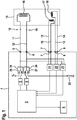
- FIG. 1 is the control device 1 for the resolver in the center, which may be integrated in the control device for a vehicle (not shown here). It has (or uses) a processor 2 which monitors the correct execution of all resolver functions to be controlled and also indicates malfunctions if necessary.
- control device 1 controls the power stages 3 and 4 for providing the sinusoidal exciter signal for the excitation coil 16 of the resolver 15 at the first terminals 5 and 6.
- the signals of the sine coil 17 and the cosine coil 18, the represent instantaneous angular position of the measuring object (eg the shaft of the motor) to the control device 1 and can be processed by the software after conversion in the AD converters 21 and 22 as a digital signal.
- the resolver excitation lines 11 and 12 represent the connection from the first terminals of the control device 1 to the resolver 15, namely to its exciter coil 16. These lines are to be monitored for interruption, which is shown in FIG. 1 with the potential interruptions 10 is indicated. From the sine coil 17 and the cosine coil 18 of the resolver 15, the signal lines 13 and 14 go to the second terminals 7 and 8 of the control device 1.
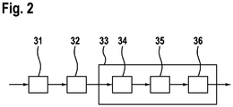
- the method for detecting an open resolver excitation line (10) begins with step 31 (cf. Fig. 2 ), in which the resolver signals are permanently measured at the second terminals 7 and 8 and evaluated by the processor 2 in such a way that the amplitude of the measurement signal is determined, which is the sum of the square of the signal U S of the sine coil 17 and the square of the signal U C of the cosine coil 18 results.
- This amplitude of the resolver signal U S 2 + U C 2 is compared with a first threshold value C S1 (step 32) and if this threshold value is undershot, ie if the resolver signal is absent, a diagnostic mode (step 33) is started.
- the excitation lines 11 and 12 and the excitation coil 16 are examined in more detail by trying to direct a DC current through them for a short time, for example for a field of excitation.
- power level 3 could also be controlled by the processor 2 in such a way that instead of the sinusoidal signal it outputs a time-constant voltage to ground, whereby the switch 26 would be saved.
- the terminal 6 is connected via a series resistor 25 R LE to ground.
- the resistance R LE of the series resistor 25 is large compared to the ohmic resistance R E of the excitation coil 16 is selected.
- the terminals 5 and 6 are connected via the excitation coil 16 low resistance to each other and therefore at almost the same potential, since the voltage drop mainly takes place at the resistor 25. If, however, there is an interruption, the voltage drop occurs between the first terminals 5 and 6 and can be measured there as a DC voltage difference.
- the processor 2 receives this information, the first terminals 5 and 6 are connected to the input of a third AD converter 23, the output of which is supplied to the processor 2.
- the voltage difference U E (t 1 ) is measured at the terminals 5 and 6 of the exciter line (method step 35 in FIG Fig. 2 ) at a plurality of times t i during at least one exciter period, namely during the time for which the terminals 5 and 6 of the exciter lines 11 and 12 are supplied with the DC voltage by means of the switching arrangement 24.
- the processor 2 determines from the measured values of the AD converter 23 the DC voltage component U E, Offs of the voltage difference U E (t L ) between the first terminals 5 and 6 (method step 36) and determines that an open exciter line 10 is present when the excitation period of DC voltage component U E, Offs is greater than a second threshold value C S2 .
- the necessary measures can be taken;
- the detection of the error is displayed or stored with a display and / or storage device 9, and the faulty line is named, for example, with its color or reference number.
- the excitation line has no interruption 10
- other causes for the absence of the resolver signal at the second terminals 7 and 8 can be researched.
Landscapes
- Physics & Mathematics (AREA)
- General Physics & Mathematics (AREA)
- Electromagnetism (AREA)
- Engineering & Computer Science (AREA)
- General Engineering & Computer Science (AREA)
- Transmission And Conversion Of Sensor Element Output (AREA)
- Testing Of Short-Circuits, Discontinuities, Leakage, Or Incorrect Line Connections (AREA)
Description
Die Erfindung betrifft ein Verfahren zum Erkennen einer offenen Resolver-Erregerleitung und eine Schaltung zum Realisieren dieses Verfahrens.The invention relates to a method for detecting an open resolver excitation line and a circuit for implementing this method.
Resolver dienen zum Ermitteln der Winkelstellung eines rotierenden Objekts, z.B. der Antriebswelle eines Motors. Im Stand der Technik gibt es verschiedene Resolvertypen. Grundsätzlich wird dabei mittels mindestens einer Spule ein sich änderndes magnetisches Feld erzeugt, und mittels mindestens einer weiteren Spule wird dieses Feld detektiert, wobei die Stärke der Kopplung zwischen den Spulen in Abhängigkeit von der zu messenden Position oder Winkelstellung variiert. Beim "Variable Reluctance Resolver" (VR-Resolver) beispielsweise kommt nur eine Erregerspule zum Einsatz und es gibt zwei Messspulen, die positionsabhängige Signale erzeugen. Die deutsche Patentanmeldung
Die Erfindung geht von einem solchen Resolver aus, wobei das Erregersignal sinusförmig ist und typischerweise eine Frequenz von 10 kHz hat. Die beiden Messspulen sind in der Regel orthogonal zueinander positioniert und werden als Sinus- und Kosinusspule bezeichnet. Mit den beiden Messsignalen ist der Winkel des Messobjekts eindeutig bestimmbar.The invention is based on such a resolver, wherein the excitation signal is sinusoidal and typically has a frequency of 10 kHz. The two measuring coils are usually positioned orthogonal to each other and are referred to as sine and cosine coil. With the two measurement signals, the angle of the DUT can be determined unambiguously.
Das Erregersignal für die Erregerspule kann beispielsweise durch zwei Gegentaktendstufen bereitgestellt werden, je eine für die beiden Anschlüsse der Erregerspule. Die Ausgangssignale der beiden Endstufen sind dann um 180° zueinander phasenverschoben und das für die Erregerspule wirksame Erregersignal ist die Differenzspannung zwischen den Ausgängen der beiden Endstufen.The excitation signal for the excitation coil can be provided for example by two push-pull output stages, one for each of the two terminals of the exciter coil. The output signals of the two output stages are then phase-shifted by 180 ° to each other and the effective for the exciter coil excitation signal is the difference voltage between the outputs of the two output stages.
Es besteht aber auch die Möglichkeit, die Erregerspule durch nur eine Endstufe zu betreiben. Der zweite Anschluss der Erregerspule ist dann entweder direkt oder über einen Kondensator auf ein festes Potential, z.B. Massepotential gelegt.But it is also possible to operate the excitation coil through only one power amplifier. The second terminal of the excitation coil is then either directly or via a capacitor to a fixed potential, e.g. Ground potential laid.
An den Empfängerspulen entsteht ein Wechselspannungssignal mit derselben Frequenz wie das Erregersignal, dessen Amplitude jedoch entsprechend der Rotorlage moduliert ist, wobei das Signal an der Kosinusspule um 90° gegenüber dem Signal an der Sinusspule phasenverschoben ist.At the receiver coils produces an AC signal with the same frequency as the excitation signal, the amplitude of which is modulated according to the rotor position, wherein the signal on the cosine coil is phase-shifted by 90 ° relative to the signal on the sinusoidal coil.
Resolver werden häufig zur Regelung von permanenterregten Synchronmaschinen (PSM) und elektrisch erregten Synchronmaschinen (ESM) eingesetzt, die z.B. als Antrieb für Hybrid- und Elektrofahrzeuge Verwendung finden. Für eine solche Regelung ist die Kenntnis der aktuellen Rotorwinkellage notwendig. Bei der Regelung von Asynchronmaschinen (ASM) ist die Kenntnis der aktuellen Frequenz des Antriebs erforderlich.Resolvers are often used to control permanent magnet synchronous machines (PSM) and electrically excited synchronous machines (ESM), which are used e.g. used as drive for hybrid and electric vehicles. For such a regulation, the knowledge of the current rotor angle position is necessary. In the control of asynchronous machines (ASM) knowledge of the current frequency of the drive is required.
Wegen ihrer Robustheit werden in Kraftfahrzeugen für diese Zwecke bevorzugt Resolver eingesetzt, auch wenn es alternative Sensoren gibt, z.B. digitale Winkelgeber oder Sensoren auf der Basis des Wirbelstromeffekts.Because of their robustness, resolvers are preferably used in motor vehicles for these purposes, although there are alternative sensors, e.g. digital angle sensors or sensors based on the eddy current effect.
Für Sensoren im Automobilbereich sind Diagnosemöglichkeiten möglicher Fehler wünschenswert. Bei Resolvern, wie sie die vorliegende Anmeldung zum Gegenstand hat, ist ein möglicher, zu diagnostizierender Fehler eine offene Leitung im Erregerpfad des Resolvers, d.h. zumindest ein Anschluss der Erregerspule hat keine elektrische Verbindung zur Ansteuerung mehr, oder es liegt ein Kabelbruch innerhalb der Erregerspule vor.For sensors in the automotive sector, diagnostic options for possible errors are desirable. Resolvers, as the subject of the present application, is a possible fault to be diagnosed an open line in the excitation path of the resolver, ie at least one terminal of the excitation coil has no electrical connection to the drive more, or there is a cable break within the exciter coil ,
Eine Möglichkeit, einen solchen Fehler zu diagnostizieren besteht darin, dass beide Empfängersignale (Sinus und Kosinus) nicht mehr vorhanden sind. Eine solche Diagnose reicht jedoch nicht aus, weil das Ausbleiben von Sinus- und Kosinussignal auch andere Ursachen haben kann, z.B. einen Kurzschluss in der Erregerleitung oder eine gleichzeitige Unterbrechung beider Empfängersignale.One way to diagnose such an error is that both receiver signals (sine and cosine) are no longer present. However, such a diagnosis is insufficient because the absence of sine and cosine signals can have other causes, e.g. a short circuit in the excitation line or a simultaneous interruption of both receiver signals.
Das Verfahren zum Erkennen einer offenen Resolver-Erregerleitung umfasst zunächst eine permanente Überwachung der Funktion des Resolvers durch das Abgreifen der Signalspannungen von der Sinus- und der Kosinusspule und das Vergleichen der daraus errechneten vektoriellen Amplitude der Summe der Signalspannungen mit einem ersten Schwellwert. Erreicht dieses Signal den Schwellenwert nicht, so wird ein Diagnosemodus gestartet, bei dem die Erregerleitung für die Zeit von mindestens einer Erregerperiode über einen Vorwiderstand mit einer Gleichspannung beaufschlagt wird, und es wird während dieser Zeit die Spannungsdifferenz an den Anschlüssen der Erregerleitung gemessen. Die Erregerleitung wird als offen erkannt, wenn der Gleichspannungsanteil dieser Spannungsdifferenz größer als ein zweiter Schwellwert ist. Unter einer Erregerperiode wird insbesondere eine Periode des Erregersignals verstanden, welches üblicherweise sinusförmig ist.The method for detecting an open resolver excitation line initially comprises permanent monitoring of the function of the resolver by picking up the signal voltages from the sine and cosine coils and comparing the calculated vectorial amplitude of the sum of the signal voltages with a first threshold value. If this signal does not reach the threshold value, a diagnostic mode is started in which the exciter line is supplied with a DC voltage via a series resistor for the time of at least one excitation period, and during this time the voltage difference at the terminals of the exciter line is measured. The excitation line is recognized as open if the DC voltage component of this voltage difference is greater than a second threshold value. An exciter period is understood in particular to be a period of the exciter signal, which is usually sinusoidal.
Ein anderer Aspekt der Erfindung besteht in einer Schaltung, die dieses Verfahren realisiert. Die Schaltung geht aus von der zu untersuchenden Schaltung, die eine Steuervorrichtung mit einem Prozessor und einer Leistungsstufe zum Bereitstellen des Signals für die Erregerleitung umfasst, weiterhin die zu diagnostizierenden Erregerleitung zu der Erregerspule des Resolvers und die Signalleitungen für das Sinus- und Kosinussignal, die zurück zur Steuervorrichtung verlaufen. Die Schaltung umfasst weiterhin zwei AD-Wandler, die an die Anschlüsse für die Signalleitungen angeschlossen sind und deren Ausgänge von dem Prozessors lesbar und verarbeitbar sind.Another aspect of the invention is a circuit that implements this method. The circuit is based on the circuit to be examined, which comprises a control device with a processor and a power stage for providing the signal for the exciter line, the exciter line to be diagnosed to the exciter coil of the resolver and the signal lines for the sine and cosine signal, the back run to the control device. The circuit further comprises two A / D converters connected to the terminals for the signal lines and whose outputs are readable and processable by the processor.
Weiterhin umfasst die Schaltung vom Prozessor gesteuerte elektronische Schalter zum Aufschalten einer konstanten Spannung auf die beiden Ausgänge für das Erregersignal über einen Vorwiderstand und sie umfasst einen am Ausgang für das Erregersignal angeschlossenen dritten AD-Wandler, der mit dem Prozessors verbunden ist. Schließlich umfasst die Schaltung eine Anzeige- und/oder Speichereinrichtung zum Anzeigen und/oder Speicher der vom Prozessor identifizierten Informationen, in die das positive Erkennen einer offenen Erregerleitung des Resolvers und das Bezeichnen der offenen Leitung einbezogen sind.Furthermore, the circuit comprises processor-controlled electronic switches for applying a constant voltage to the two outputs for the exciter signal via a series resistor and comprises an am Output for the excitation signal connected third AD converter, which is connected to the processor. Finally, the circuit comprises a display and / or memory device for displaying and / or storing the information identified by the processor, in which the positive detection of an open exciter line of the resolver and the designation of the open line are included.
Der Vorteil der Erfindung besteht darin, dass der zu diagnostizierende Fehler exakt von anderen Fehlern unterschieden werden kann (PinPointing-Diagnose). Die Diagnose ist auch sehr schnell, denn bereits nach wenigen Perioden des Erregresignals mit einer typischen Dauer von 0,1 ms liegt eine zuverlässige Fehlerdiagnose vor, und es können ggf. geeignete Maßnahmen ergriffen werden. Damit können insbesondere Anforderungen an Sensoren im Automobilbereich im Hinblick auf funktionelle Sicherheit wie auch im Hinblick auf OBD-Funktionalität (OBD = On Board Diagnose) erfüllt werden.The advantage of the invention is that the error to be diagnosed can be distinguished exactly from other errors (PinPointing diagnosis). The diagnosis is also very fast, because even after a few periods of the excitation signal with a typical duration of 0.1 ms, a reliable fault diagnosis is available, and suitable measures can be taken if necessary. In particular, requirements for sensors in the automotive sector can be met in terms of functional safety as well as with regard to OBD functionality (OBD = on-board diagnostics).
Vorteilhaft ist weiterhin, dass das erfindungsgemäße Verfahren mit minimaler Ergänzung der üblichen Hardware einer Resolveransteuerung realisiert werden kann.A further advantage is that the method according to the invention can be implemented with minimal supplementation of the usual hardware of a resolver drive.
Kurze Beschreibung der Zeichnungen
-
Fig. 1 zeigt eine Schaltung gemäß einem Ausführungsbeispiel der Erfindung. -
Fig. 2 erläutert schematisch die Schritte zum Ausführen des Verfahrens gemäß einem Ausführungsbeispiel der Erfindung.
-
Fig. 1 shows a circuit according to an embodiment of the invention. -
Fig. 2 schematically illustrates the steps for carrying out the method according to an embodiment of the invention.
In
Die Steuervorrichtung 1 steuert insbesondere die Leistungsstufen 3 und 4 zum Bereitstellen des sinusförmigen Erregersignals für die Erregerspule 16 des Resolvers 15 an den ersten Anschlüssen 5 und 6. An den zweiten Anschlüssen 7 und 8 gelangen die Signale der Sinusspule 17 und der Kosinusspule 18, die die momentane Winkelstellung des Messobjekts (z.B. der Welle des Motors) repräsentieren, zur Steuervorrichtung 1 und können nach Wandlung in den AD-Wandlern 21 und 22 als digitales Signal softwaremäßig weiter bearbeitet werden.In particular, the control device 1 controls the
Die Resolver-Erregerleitungen 11 und 12 stellen die Verbindung von den ersten Anschlüssen der Steuervorrichtung 1 zum Resolver 15, nämlich zu dessen Erregerspule 16 dar. Diese Leitungen gilt es im Hinblick auf eine Unterbrechung zu überwachen, was in
Das Verfahren zum Erkennen einer offenen Resolver-Erregerleitung (10) beginnt mit dem Schritt 31 (vgl.
Im Diagnosemodus 33 werden die Erregerleitungen 11 und 12 und die Erregerspule 16 näher untersucht, indem versucht wird, für eine kurze Zeit, z.B. für eine Erregerperiode, durch sie einen Gleichstrom zu leiten. Hierfür ist eine Schaltvorrichtung 24 vorgesehen, die hardwaremäßig aus zwei vom Prozessor 2 gesteuerten elektronischen Schaltern 26 und 27 bestehen kann. Mit dem Schalter 26 kann eine Gleichspannung U= auf den Anschluss 5 geschaltet werden. Alternativ hierzu könnte auch Leistungsstufe 3 so vom Prozessor 2 angesteuert werden, dass sie statt des Sinussignals eine zeitlich konstante Spannung gegen Masse abgibt, wodurch der Schalter 26 eingespart würde.In the
Durch Umlegen des Schalters 27, gleichzeitig mit dem Schalter 26, wird der Anschluss 6 über einen Vorwiderstand 25 RLE mit Masse verbunden. Der Vorwiderstand 25 ist im dargestellten Fall in den Massezweig gelegt, der zum Anschluss 6 geschaltet wird; er könnte aber genauso gut in den Zweig zur Gleichspannung U= gelegt sein, der zum Anschluss 5 geschaltet wird.By turning the
Durch Betätigen der Schalter 26 und 27 wird jedenfalls ein Gleichstrom-Stromkreis durch die Leitungen 11 und 12 und die Erregerspule 16 temporär geschlossen.In any case, by actuating the
Der Widerstandswert RLE des Vorwiderstands 25 ist groß im Vergleich zum ohmschen Widerstand RE der Erregerspule 16 gewählt. Bei unterbrechungsfreiem Erregerleitungen 11 und 12, wenn also der zu diagnostizierende Fehler nicht vorliegt, sind die Anschlüsse 5 und 6 über die Erregerspule 16 niederohmig miteinander verbunden und daher auf nahezu gleichem Potential, da der Spannungsabfall hauptsächlich am Vorwiderstand 25 erfolgt. Liegt hingegen eine Unterbrechung vor, so entsteht der Spannungsabfall zwischen den ersten Anschlüssen 5 und 6 und ist dort als Gleichspannungsdifferenz messbar.The resistance R LE of the
Damit der Prozessor 2 diese Information erhält, sind die ersten Anschlüsse 5 und 6 mit Eingang eines dritten AD-Wandler 23 verbunden, dessen Ausgang dem Prozessor 2 zugeführt wird. Somit erfolgt ein Messen der Spannungsdifferenz UE(tl) an den Anschlüssen 5 und 6 der Erregerleitung (Verfahrensschritt 35 in
Der Prozessor 2 ermittelt aus den Messwerten des AD-Wandlers 23 den Gleichspannungsanteils UE,Offs der Spannungsdifferenz UE(tl) zwischen den ersten Anschlüssen 5 und 6 (Verfahrensschritt 36) und stellt fest, dass eine offene Erregerleitung 10 vorliegt, wenn während der Erregerperiode der Gleichspannungsanteil UE,Offs größer als ein zweiter Schwellwert CS2 ist. Das Ermitteln des Gleichspannungsanteils kann dabei softwaremäßig in unterschiedlicher Weise erfolgen. Eine Möglichkeit besteht darin, gemäß der Formel ![]()
![]()
![]()
![]()
Auf der Basis der Feststellung, ob der Gleichspannungsanteil UE,Offs größer als der zweite Schwellwert CS2 ist oder nicht, und damit, ob eine offene Erregerleitung 10 diagnostiziert wird oder nicht, können die erforderlichen Maßnahmen erfolgen; insbesondere wird das Feststellen des Fehlers mit einer Anzeige- und/oder Speichereinrichtung 9 angezeigt bzw. gespeichert, und die fehlerhafte Leitung wird z.B. mit ihrer Farbe oder Bezugsnummer benannt. In dem Fall, dass die Erregerleitung keine Unterbrechung 10 aufweist, kann insbesondere nach anderen Ursachen für das Ausbleiben des Resolversignals an den zweiten Anschlüssen 7 und 8 geforscht werden.On the basis of the determination as to whether or not the DC voltage component U E, Offs is greater than the second threshold value C S2 , and thus whether or not an
Claims (9)
- Method for identifying an open resolver exciter line (10), comprising the following steps:measuring the signal voltages (31) from the sinusoidal coil (17) and the cosinusoidal coil (18) of the resolver;comparing the amplitude (32) of the resolver signal, which amplitude is formed by the sum of the squared signal voltages, with a first threshold value;starting a diagnosis mode (33) comprising the following steps if the formed amplitude does not reach the first threshold value:applying (34) a constant voltage to the connections (5, 6) of the exciter line (11, 12) via a series resistor (25), which is large in comparison to the non-reactive resistance of the exciter coil (16), for the duration of at least one exciter period;measuring the voltage difference (35) at the connections (5, 6) of the exciter line at a plurality of times while the DC voltage is applied; andascertaining the DC voltage component (36) of the voltage difference;establishing (37) an open exciter line (10) when the DC voltage component is greater than a second threshold value during the exciter period.
- Method according to Claim 1, wherein the application operation (34) is performed by switching a connection to a DC voltage potential to one connection (5) of the exciter coil and switching a connection to ground via the series resistor (25) to the other connection (6) of the exciter coil.
- Method according to Claim 1, wherein the application operation (34) is performed by driving one of the output stages (3, 4) of the exciter circuit at a constant voltage for one connection (5) of the exciter coil and by switching a connection to ground via the series resistor (25) to the other connection (6) of the exciter coil.
- Method according to one of Claims 1 to 3, wherein the voltage difference (35) at the connections (5, 6) of the exciter lines (11, 12 is measured at several times during at least one excitation period.
- Method according to one of Claims 1 to 4, wherein the DC voltage component (35) is ascertained depending on a sum of the maximum and minimum measured voltage difference and, when forming the maximum and minimum measured voltage difference, those measurement points are taken into account provided that a DC voltage is applied.
- Method according to one of Claims 1 to 4, wherein the times are equidistant, the DC voltage component (35) is ascertained depending on the mean value of the measured voltage differences while one DC voltage is applied, and wherein the voltage differences are ascertained over an exciter period or a multiple thereof.
- Circuit for identifying an open resolver exciter line (10), having:a control apparatus (1) with a processor (2), power stages (3, 4) and first connections (5, 6) for providing signals for the exciter lines (11, 12) to the exciter coil (16) of the resolver (15) and second connections (7, 8) for connecting the signal lines (13, 14) for the signals of the sinusoidal and the cosinusoidal coil (17, 18);two A/D converters (21, 22) which are connected to the second connections (7, 8) of the control device (1) for the signal lines (13, 14) and the outputs of which can be read and evaluated by the processor (2), wherein the processor (2) is configured to carry out the method steps according to Claim 1;the resolver exciter lines (11, 12) which are to be diagnosed and couple the first connections (5, 6) to the exciter coil (16) of the resolver (15);andsignal lines (13, 14) for the sinusoidal signal and cosinusoidal signal which are provided by the resolver (15) and couple the resolver (15) to second connections (7, 8) of the control apparatus (1);an electronic switching arrangement (24), which is controlled by the processor (2), for temporarily connecting a DC voltage to the first connections (5, 6) for the exciter signal via a series resistor (25);a third A/D converter (23) which is connected to the first connections (5, 6) of the control device (1) and the output of which can be read and evaluated by the processor (2); anda display and/or storage device (9) for displaying and/or storing the information which is identified by the processor (2) and which includes the positive identification of an open line (10) of the resolver exciter coil (16).
- Circuit according to Claim 7, wherein the electronic switching arrangement (24) comprises a switch (27) by means of which a connection (6) for the exciter line (11) can be temporarily connected to ground via a series resistor (25).
- Circuit according to Claim 7 or 8, wherein the electronic switching arrangement (24) comprises a switch (26) by means of which a DC voltage with respect to ground can be temporarily applied to a connection (5) for the exciter line (11).
Applications Claiming Priority (2)
| Application Number | Priority Date | Filing Date | Title |
|---|---|---|---|
| DE102015211224.1A DE102015211224A1 (en) | 2015-06-18 | 2015-06-18 | Method and circuit for detecting an open resolver exciter line |
| PCT/EP2016/062852 WO2016202631A1 (en) | 2015-06-18 | 2016-06-07 | Method and circuit for detecting an open resolver exciter line |
Publications (2)
| Publication Number | Publication Date |
|---|---|
| EP3311107A1 EP3311107A1 (en) | 2018-04-25 |
| EP3311107B1 true EP3311107B1 (en) | 2019-04-24 |
Family
ID=56132902
Family Applications (1)
| Application Number | Title | Priority Date | Filing Date |
|---|---|---|---|
| EP16729519.5A Active EP3311107B1 (en) | 2015-06-18 | 2016-06-07 | Method and circuit for detecting an open resolver exciter line |
Country Status (5)
| Country | Link |
|---|---|
| US (1) | US10495684B2 (en) |
| EP (1) | EP3311107B1 (en) |
| CN (1) | CN107735651B (en) |
| DE (1) | DE102015211224A1 (en) |
| WO (1) | WO2016202631A1 (en) |
Families Citing this family (2)
| Publication number | Priority date | Publication date | Assignee | Title |
|---|---|---|---|---|
| CN110895131A (en) * | 2018-09-12 | 2020-03-20 | 广州汽车集团股份有限公司 | Monitoring method and system for excitation signal and response signal of rotary transformer |
| DE102019200318A1 (en) * | 2019-01-11 | 2020-07-16 | Zf Friedrichshafen Ag | Resolver circuit |
Family Cites Families (24)
| Publication number | Priority date | Publication date | Assignee | Title |
|---|---|---|---|---|
| JPH09113205A (en) * | 1995-10-19 | 1997-05-02 | Denso Corp | Resolver excitation device |
| JP3460587B2 (en) * | 1998-07-21 | 2003-10-27 | トヨタ自動車株式会社 | Abnormality detector that detects abnormality of the rotation angle detector |
| US6426712B1 (en) * | 2000-11-16 | 2002-07-30 | Analog Devices, Inc. | Fault-signal generators and methods for resolver systems |
| DE10221878A1 (en) * | 2001-06-01 | 2003-01-16 | Omron Corp Kyoto | Contact displacement detector for measuring dimensions and shape of device components or assemblies at factory, has amplitude adjustment unit which changes amplitude of driving signal to constant value |
| JP2005024493A (en) * | 2003-07-02 | 2005-01-27 | Nissan Motor Co Ltd | Abnormality detector for resolver |
| JP4521258B2 (en) * | 2004-01-28 | 2010-08-11 | 日立オートモティブシステムズ株式会社 | Resolver / digital converter and control system using the same |
| JP4475642B2 (en) * | 2004-06-22 | 2010-06-09 | 株式会社ジェイテクト | Resolver abnormality detection device and vehicle transmission ratio variable steering device using the same |
| US7288933B2 (en) * | 2005-12-22 | 2007-10-30 | Bell Helicopter Textron, Inc. | Position detecting system that self-monitors for connectivity faults |
| JP5011824B2 (en) * | 2006-05-31 | 2012-08-29 | 株式会社ジェイテクト | Abnormality judgment device |
| JP5045407B2 (en) * | 2007-12-07 | 2012-10-10 | 株式会社ジェイテクト | Resolver abnormality detection device and electric power steering device |
| JP4929189B2 (en) * | 2008-01-09 | 2012-05-09 | 日立オートモティブシステムズ株式会社 | Resolver abnormality detection circuit |
| JP5028294B2 (en) * | 2008-02-14 | 2012-09-19 | 日立オートモティブシステムズ株式会社 | Resolver abnormality detection device |
| DE102009020431A1 (en) | 2008-05-13 | 2009-11-19 | Continental Teves Ag & Co. Ohg | Sensor device and error detection method for electronic circuits in motor vehicles |
| JP2011089935A (en) * | 2009-10-23 | 2011-05-06 | Toyota Motor Corp | Resolver abnormality detector |
| KR101039676B1 (en) * | 2009-11-04 | 2011-06-09 | 현대자동차주식회사 | Circuit and method for detection short and disconnection of resolver for HEV |
| DE102009046925A1 (en) * | 2009-11-20 | 2011-05-26 | Lenze Automation Gmbh | A method, apparatus and system for monitoring the determination of a rotor angle of a rotating shaft by means of a resolver |
| JP5051404B2 (en) | 2010-08-25 | 2012-10-17 | トヨタ自動車株式会社 | Torque detection device |
| JP2012098188A (en) * | 2010-11-02 | 2012-05-24 | Denso Corp | Abnormality diagnostic device in rotation angle detection system |
| JP5494969B2 (en) * | 2010-11-04 | 2014-05-21 | 株式会社デンソー | Abnormality diagnosis device for rotation angle detection system |
| CN102656432B (en) * | 2010-12-24 | 2014-07-02 | 丰田自动车株式会社 | Torque detection device |
| DE102011078583A1 (en) | 2011-07-04 | 2013-01-10 | Robert Bosch Gmbh | Evaluation of resolver sensor signals |
| JP2015187560A (en) * | 2014-03-26 | 2015-10-29 | トヨタ自動車株式会社 | resolver excitation circuit |
| DE102015211232A1 (en) * | 2015-06-18 | 2016-12-22 | Robert Bosch Gmbh | Method and circuit for detecting an open line of the sine / cosine receiver coil of a resolver |
| DE102015211214A1 (en) * | 2015-06-18 | 2016-12-22 | Robert Bosch Gmbh | Method and circuit for detecting a short circuit of a resolver excitation line to ground or to the operating voltage |
-
2015
- 2015-06-18 DE DE102015211224.1A patent/DE102015211224A1/en not_active Withdrawn
-
2016
- 2016-06-07 US US15/737,533 patent/US10495684B2/en active Active
- 2016-06-07 EP EP16729519.5A patent/EP3311107B1/en active Active
- 2016-06-07 WO PCT/EP2016/062852 patent/WO2016202631A1/en active Application Filing
- 2016-06-07 CN CN201680035718.1A patent/CN107735651B/en active Active
Non-Patent Citations (1)
| Title |
|---|
| None * |
Also Published As
| Publication number | Publication date |
|---|---|
| CN107735651A (en) | 2018-02-23 |
| US20180172757A1 (en) | 2018-06-21 |
| US10495684B2 (en) | 2019-12-03 |
| CN107735651B (en) | 2020-07-07 |
| WO2016202631A1 (en) | 2016-12-22 |
| DE102015211224A1 (en) | 2016-12-22 |
| EP3311107A1 (en) | 2018-04-25 |
Similar Documents
| Publication | Publication Date | Title |
|---|---|---|
| EP3311115B1 (en) | Method and circuit for detecting an open line of the sine/cosine receiver coil of a resolver | |
| DE102017127799A1 (en) | FAULT TOLERANT MEASUREMENT OF PHASE FLOWS FOR MOTOR CONTROL SYSTEMS | |
| EP3311106B1 (en) | Method and circuit for detecting a short circuit of the sine or cosine receiver coil of a resolver | |
| EP3311107B1 (en) | Method and circuit for detecting an open resolver exciter line | |
| DE102019205561A1 (en) | Method for diagnosing an electric motor | |
| EP2391902B1 (en) | Method for operating a brushless motor | |
| EP3311119B1 (en) | Control circuit and method for checking the plausibility of a rotor position angle | |
| EP3311114B1 (en) | Method and circuit for detecting a short circuit of a resolver exciter line to ground or to the operating voltage | |
| DE102005004174A1 (en) | Motor vehicle battery diagnosis method, involves characterizing motor vehicle battery as defective, if amplitude of battery power e.g. charging power or discharging power, falls below given power threshold value | |
| DE102018002188A1 (en) | Method for testing a drive and drive | |
| DE102012223581A1 (en) | Apparatus and method for monitoring signal levels | |
| EP3529890B1 (en) | Control system for a synchronous machine and method for operating a synchronous machine | |
| EP3532857B1 (en) | Device and method for diagnosing the detection of a multi-phase electric current | |
| DE102019200318A1 (en) | Resolver circuit | |
| DE102012220843A1 (en) | Method for characterizing stator of rotating-field machine, involves interrupting electrical connection between one side of first input terminal of stator and another side of input potentials of inverter | |
| EP4016835A1 (en) | Method for determining the angular position of the rotor of a synchronous motor fed by an inverter and device for carrying out the method | |
| EP4187208A1 (en) | Assembly and method for position detection with error detection with a position sensor | |
| DE102019212900A1 (en) | Detection of defects in rectifier voltage regulator modules | |
| DE102013213053A1 (en) | Angle of rotation sensor device with redundant sensor units | |
| EP3297153A1 (en) | Method and device for determining a position of a rotor of an electronically commutated electrical machine | |
| DE102021117082A1 (en) | Electronic circuit arrangement for determining an offset angle for an electrical machine with detection of zero crossings | |
| DE102019107725A1 (en) | Apparatus and a method for detecting a shorted winding in a stator coil | |
| WO2018001848A1 (en) | Method and device for testing a multi-phase connection cable and bridge circuit for a multi-phase electric motor | |
| DE102017204987A1 (en) | Method and device for determining a rotation of a sensor wheel, and electric machine |
Legal Events
| Date | Code | Title | Description |
|---|---|---|---|
| STAA | Information on the status of an ep patent application or granted ep patent |
Free format text: STATUS: THE INTERNATIONAL PUBLICATION HAS BEEN MADE |
|
| PUAI | Public reference made under article 153(3) epc to a published international application that has entered the european phase |
Free format text: ORIGINAL CODE: 0009012 |
|
| STAA | Information on the status of an ep patent application or granted ep patent |
Free format text: STATUS: REQUEST FOR EXAMINATION WAS MADE |
|
| 17P | Request for examination filed |
Effective date: 20180118 |
|
| AK | Designated contracting states |
Kind code of ref document: A1 Designated state(s): AL AT BE BG CH CY CZ DE DK EE ES FI FR GB GR HR HU IE IS IT LI LT LU LV MC MK MT NL NO PL PT RO RS SE SI SK SM TR |
|
| AX | Request for extension of the european patent |
Extension state: BA ME |
|
| DAV | Request for validation of the european patent (deleted) | ||
| DAX | Request for extension of the european patent (deleted) | ||
| REG | Reference to a national code |
Ref country code: DE Ref legal event code: R079 Ref document number: 502016004346 Country of ref document: DE Free format text: PREVIOUS MAIN CLASS: G01B0007300000 Ipc: G01D0018000000 |
|
| GRAP | Despatch of communication of intention to grant a patent |
Free format text: ORIGINAL CODE: EPIDOSNIGR1 |
|
| STAA | Information on the status of an ep patent application or granted ep patent |
Free format text: STATUS: GRANT OF PATENT IS INTENDED |
|
| RIC1 | Information provided on ipc code assigned before grant |
Ipc: G01B 7/30 20060101ALN20181204BHEP Ipc: G01R 31/28 20060101ALI20181204BHEP Ipc: G01D 18/00 20060101AFI20181204BHEP Ipc: G01D 5/20 20060101ALI20181204BHEP Ipc: G01R 31/02 20060101ALI20181204BHEP |
|
| INTG | Intention to grant announced |
Effective date: 20190104 |
|
| GRAS | Grant fee paid |
Free format text: ORIGINAL CODE: EPIDOSNIGR3 |
|
| GRAA | (expected) grant |
Free format text: ORIGINAL CODE: 0009210 |
|
| STAA | Information on the status of an ep patent application or granted ep patent |
Free format text: STATUS: THE PATENT HAS BEEN GRANTED |
|
| AK | Designated contracting states |
Kind code of ref document: B1 Designated state(s): AL AT BE BG CH CY CZ DE DK EE ES FI FR GB GR HR HU IE IS IT LI LT LU LV MC MK MT NL NO PL PT RO RS SE SI SK SM TR |
|
| REG | Reference to a national code |
Ref country code: GB Ref legal event code: FG4D Free format text: NOT ENGLISH |
|
| REG | Reference to a national code |
Ref country code: CH Ref legal event code: EP |
|
| REG | Reference to a national code |
Ref country code: AT Ref legal event code: REF Ref document number: 1124683 Country of ref document: AT Kind code of ref document: T Effective date: 20190515 Ref country code: IE Ref legal event code: FG4D Free format text: LANGUAGE OF EP DOCUMENT: GERMAN |
|
| REG | Reference to a national code |
Ref country code: DE Ref legal event code: R096 Ref document number: 502016004346 Country of ref document: DE |
|
| REG | Reference to a national code |
Ref country code: NL Ref legal event code: MP Effective date: 20190424 |
|
| REG | Reference to a national code |
Ref country code: LT Ref legal event code: MG4D |
|
| PG25 | Lapsed in a contracting state [announced via postgrant information from national office to epo] |
Ref country code: NL Free format text: LAPSE BECAUSE OF FAILURE TO SUBMIT A TRANSLATION OF THE DESCRIPTION OR TO PAY THE FEE WITHIN THE PRESCRIBED TIME-LIMIT Effective date: 20190424 |
|
| PG25 | Lapsed in a contracting state [announced via postgrant information from national office to epo] |
Ref country code: LT Free format text: LAPSE BECAUSE OF FAILURE TO SUBMIT A TRANSLATION OF THE DESCRIPTION OR TO PAY THE FEE WITHIN THE PRESCRIBED TIME-LIMIT Effective date: 20190424 Ref country code: FI Free format text: LAPSE BECAUSE OF FAILURE TO SUBMIT A TRANSLATION OF THE DESCRIPTION OR TO PAY THE FEE WITHIN THE PRESCRIBED TIME-LIMIT Effective date: 20190424 Ref country code: SE Free format text: LAPSE BECAUSE OF FAILURE TO SUBMIT A TRANSLATION OF THE DESCRIPTION OR TO PAY THE FEE WITHIN THE PRESCRIBED TIME-LIMIT Effective date: 20190424 Ref country code: NO Free format text: LAPSE BECAUSE OF FAILURE TO SUBMIT A TRANSLATION OF THE DESCRIPTION OR TO PAY THE FEE WITHIN THE PRESCRIBED TIME-LIMIT Effective date: 20190724 Ref country code: HR Free format text: LAPSE BECAUSE OF FAILURE TO SUBMIT A TRANSLATION OF THE DESCRIPTION OR TO PAY THE FEE WITHIN THE PRESCRIBED TIME-LIMIT Effective date: 20190424 Ref country code: PT Free format text: LAPSE BECAUSE OF FAILURE TO SUBMIT A TRANSLATION OF THE DESCRIPTION OR TO PAY THE FEE WITHIN THE PRESCRIBED TIME-LIMIT Effective date: 20190824 Ref country code: ES Free format text: LAPSE BECAUSE OF FAILURE TO SUBMIT A TRANSLATION OF THE DESCRIPTION OR TO PAY THE FEE WITHIN THE PRESCRIBED TIME-LIMIT Effective date: 20190424 Ref country code: AL Free format text: LAPSE BECAUSE OF FAILURE TO SUBMIT A TRANSLATION OF THE DESCRIPTION OR TO PAY THE FEE WITHIN THE PRESCRIBED TIME-LIMIT Effective date: 20190424 |
|
| PG25 | Lapsed in a contracting state [announced via postgrant information from national office to epo] |
Ref country code: GR Free format text: LAPSE BECAUSE OF FAILURE TO SUBMIT A TRANSLATION OF THE DESCRIPTION OR TO PAY THE FEE WITHIN THE PRESCRIBED TIME-LIMIT Effective date: 20190725 Ref country code: BG Free format text: LAPSE BECAUSE OF FAILURE TO SUBMIT A TRANSLATION OF THE DESCRIPTION OR TO PAY THE FEE WITHIN THE PRESCRIBED TIME-LIMIT Effective date: 20190724 Ref country code: RS Free format text: LAPSE BECAUSE OF FAILURE TO SUBMIT A TRANSLATION OF THE DESCRIPTION OR TO PAY THE FEE WITHIN THE PRESCRIBED TIME-LIMIT Effective date: 20190424 Ref country code: LV Free format text: LAPSE BECAUSE OF FAILURE TO SUBMIT A TRANSLATION OF THE DESCRIPTION OR TO PAY THE FEE WITHIN THE PRESCRIBED TIME-LIMIT Effective date: 20190424 Ref country code: PL Free format text: LAPSE BECAUSE OF FAILURE TO SUBMIT A TRANSLATION OF THE DESCRIPTION OR TO PAY THE FEE WITHIN THE PRESCRIBED TIME-LIMIT Effective date: 20190424 |
|
| PG25 | Lapsed in a contracting state [announced via postgrant information from national office to epo] |
Ref country code: IS Free format text: LAPSE BECAUSE OF FAILURE TO SUBMIT A TRANSLATION OF THE DESCRIPTION OR TO PAY THE FEE WITHIN THE PRESCRIBED TIME-LIMIT Effective date: 20190824 |
|
| REG | Reference to a national code |
Ref country code: DE Ref legal event code: R097 Ref document number: 502016004346 Country of ref document: DE |
|
| PG25 | Lapsed in a contracting state [announced via postgrant information from national office to epo] |
Ref country code: EE Free format text: LAPSE BECAUSE OF FAILURE TO SUBMIT A TRANSLATION OF THE DESCRIPTION OR TO PAY THE FEE WITHIN THE PRESCRIBED TIME-LIMIT Effective date: 20190424 Ref country code: DK Free format text: LAPSE BECAUSE OF FAILURE TO SUBMIT A TRANSLATION OF THE DESCRIPTION OR TO PAY THE FEE WITHIN THE PRESCRIBED TIME-LIMIT Effective date: 20190424 Ref country code: SK Free format text: LAPSE BECAUSE OF FAILURE TO SUBMIT A TRANSLATION OF THE DESCRIPTION OR TO PAY THE FEE WITHIN THE PRESCRIBED TIME-LIMIT Effective date: 20190424 Ref country code: MC Free format text: LAPSE BECAUSE OF FAILURE TO SUBMIT A TRANSLATION OF THE DESCRIPTION OR TO PAY THE FEE WITHIN THE PRESCRIBED TIME-LIMIT Effective date: 20190424 Ref country code: CZ Free format text: LAPSE BECAUSE OF FAILURE TO SUBMIT A TRANSLATION OF THE DESCRIPTION OR TO PAY THE FEE WITHIN THE PRESCRIBED TIME-LIMIT Effective date: 20190424 Ref country code: RO Free format text: LAPSE BECAUSE OF FAILURE TO SUBMIT A TRANSLATION OF THE DESCRIPTION OR TO PAY THE FEE WITHIN THE PRESCRIBED TIME-LIMIT Effective date: 20190424 |
|
| REG | Reference to a national code |
Ref country code: CH Ref legal event code: PL |
|
| PG25 | Lapsed in a contracting state [announced via postgrant information from national office to epo] |
Ref country code: SM Free format text: LAPSE BECAUSE OF FAILURE TO SUBMIT A TRANSLATION OF THE DESCRIPTION OR TO PAY THE FEE WITHIN THE PRESCRIBED TIME-LIMIT Effective date: 20190424 Ref country code: IT Free format text: LAPSE BECAUSE OF FAILURE TO SUBMIT A TRANSLATION OF THE DESCRIPTION OR TO PAY THE FEE WITHIN THE PRESCRIBED TIME-LIMIT Effective date: 20190424 |
|
| PLBE | No opposition filed within time limit |
Free format text: ORIGINAL CODE: 0009261 |
|
| STAA | Information on the status of an ep patent application or granted ep patent |
Free format text: STATUS: NO OPPOSITION FILED WITHIN TIME LIMIT |
|
| REG | Reference to a national code |
Ref country code: BE Ref legal event code: MM Effective date: 20190630 |
|
| PG25 | Lapsed in a contracting state [announced via postgrant information from national office to epo] |
Ref country code: TR Free format text: LAPSE BECAUSE OF FAILURE TO SUBMIT A TRANSLATION OF THE DESCRIPTION OR TO PAY THE FEE WITHIN THE PRESCRIBED TIME-LIMIT Effective date: 20190424 |
|
| 26N | No opposition filed |
Effective date: 20200127 |
|
| PG25 | Lapsed in a contracting state [announced via postgrant information from national office to epo] |
Ref country code: IE Free format text: LAPSE BECAUSE OF NON-PAYMENT OF DUE FEES Effective date: 20190607 |
|
| PG25 | Lapsed in a contracting state [announced via postgrant information from national office to epo] |
Ref country code: LI Free format text: LAPSE BECAUSE OF NON-PAYMENT OF DUE FEES Effective date: 20190630 Ref country code: BE Free format text: LAPSE BECAUSE OF NON-PAYMENT OF DUE FEES Effective date: 20190630 Ref country code: LU Free format text: LAPSE BECAUSE OF NON-PAYMENT OF DUE FEES Effective date: 20190607 Ref country code: SI Free format text: LAPSE BECAUSE OF FAILURE TO SUBMIT A TRANSLATION OF THE DESCRIPTION OR TO PAY THE FEE WITHIN THE PRESCRIBED TIME-LIMIT Effective date: 20190424 Ref country code: CH Free format text: LAPSE BECAUSE OF NON-PAYMENT OF DUE FEES Effective date: 20190630 |
|
| GBPC | Gb: european patent ceased through non-payment of renewal fee |
Effective date: 20200607 |
|
| PG25 | Lapsed in a contracting state [announced via postgrant information from national office to epo] |
Ref country code: GB Free format text: LAPSE BECAUSE OF NON-PAYMENT OF DUE FEES Effective date: 20200607 |
|
| PG25 | Lapsed in a contracting state [announced via postgrant information from national office to epo] |
Ref country code: CY Free format text: LAPSE BECAUSE OF FAILURE TO SUBMIT A TRANSLATION OF THE DESCRIPTION OR TO PAY THE FEE WITHIN THE PRESCRIBED TIME-LIMIT Effective date: 20190424 |
|
| PG25 | Lapsed in a contracting state [announced via postgrant information from national office to epo] |
Ref country code: MT Free format text: LAPSE BECAUSE OF FAILURE TO SUBMIT A TRANSLATION OF THE DESCRIPTION OR TO PAY THE FEE WITHIN THE PRESCRIBED TIME-LIMIT Effective date: 20190424 Ref country code: HU Free format text: LAPSE BECAUSE OF FAILURE TO SUBMIT A TRANSLATION OF THE DESCRIPTION OR TO PAY THE FEE WITHIN THE PRESCRIBED TIME-LIMIT; INVALID AB INITIO Effective date: 20160607 |
|
| PG25 | Lapsed in a contracting state [announced via postgrant information from national office to epo] |
Ref country code: MK Free format text: LAPSE BECAUSE OF FAILURE TO SUBMIT A TRANSLATION OF THE DESCRIPTION OR TO PAY THE FEE WITHIN THE PRESCRIBED TIME-LIMIT Effective date: 20190424 |
|
| REG | Reference to a national code |
Ref country code: AT Ref legal event code: MM01 Ref document number: 1124683 Country of ref document: AT Kind code of ref document: T Effective date: 20210607 |
|
| PG25 | Lapsed in a contracting state [announced via postgrant information from national office to epo] |
Ref country code: AT Free format text: LAPSE BECAUSE OF NON-PAYMENT OF DUE FEES Effective date: 20210607 |
|
| PGFP | Annual fee paid to national office [announced via postgrant information from national office to epo] |
Ref country code: FR Payment date: 20230621 Year of fee payment: 8 |
|
| PGFP | Annual fee paid to national office [announced via postgrant information from national office to epo] |
Ref country code: DE Payment date: 20230817 Year of fee payment: 8 |