EP3305071A1 - Control system, agricultural vehicle and method of controlling an agricultural vehicle - Google Patents
Control system, agricultural vehicle and method of controlling an agricultural vehicle Download PDFInfo
- Publication number
- EP3305071A1 EP3305071A1 EP17401105.6A EP17401105A EP3305071A1 EP 3305071 A1 EP3305071 A1 EP 3305071A1 EP 17401105 A EP17401105 A EP 17401105A EP 3305071 A1 EP3305071 A1 EP 3305071A1
- Authority
- EP
- European Patent Office
- Prior art keywords
- linkage
- joint
- distributor linkage
- control system
- utility vehicle
- Prior art date
- Legal status (The legal status is an assumption and is not a legal conclusion. Google has not performed a legal analysis and makes no representation as to the accuracy of the status listed.)
- Withdrawn
Links
Images


Classifications
-
- A—HUMAN NECESSITIES
- A01—AGRICULTURE; FORESTRY; ANIMAL HUSBANDRY; HUNTING; TRAPPING; FISHING
- A01M—CATCHING, TRAPPING OR SCARING OF ANIMALS; APPARATUS FOR THE DESTRUCTION OF NOXIOUS ANIMALS OR NOXIOUS PLANTS
- A01M7/00—Special adaptations or arrangements of liquid-spraying apparatus for purposes covered by this subclass
- A01M7/005—Special arrangements or adaptations of the spraying or distributing parts, e.g. adaptations or mounting of the spray booms, mounting of the nozzles, protection shields
- A01M7/0071—Construction of the spray booms
- A01M7/0078—Construction of the spray booms including break-away devices
-
- A—HUMAN NECESSITIES
- A01—AGRICULTURE; FORESTRY; ANIMAL HUSBANDRY; HUNTING; TRAPPING; FISHING
- A01M—CATCHING, TRAPPING OR SCARING OF ANIMALS; APPARATUS FOR THE DESTRUCTION OF NOXIOUS ANIMALS OR NOXIOUS PLANTS
- A01M7/00—Special adaptations or arrangements of liquid-spraying apparatus for purposes covered by this subclass
- A01M7/005—Special arrangements or adaptations of the spraying or distributing parts, e.g. adaptations or mounting of the spray booms, mounting of the nozzles, protection shields
- A01M7/0071—Construction of the spray booms
- A01M7/0075—Construction of the spray booms including folding means
Definitions
- the invention relates to a control system for an agricultural utility vehicle according to the preamble of claim 1. Furthermore, the invention relates to an agricultural utility vehicle according to claim 13, and a method for controlling an agricultural utility vehicle according to claim 14.
- Such control systems are used for agricultural vehicles to disperse material such as fertilizers, pesticides or seeds.
- the agricultural vehicles To spread the material over a large area and efficiently on the field to be processed, the agricultural vehicles have a distributor linkage with several spray nozzles.
- the distribution link extends transversely to the direction of travel and can have working widths of up to 40m.
- the spray nozzles which are mounted at a regular distance on the distributor linkage, serve to apply the material to the field to be processed.
- the distance between the distribution linkage and the soil or the upper edge of the crop is to remain as constant as possible over the entire working width of the distribution linkage. This means that the distribution linkage is kept as parallel as possible to the working soil.
- the distribution linkage has a plurality of linkage sections, which are foldable, so that the distribution linkage can be transferred from a space-saving transport position into a working position with the full working width.
- the transport position here describes the folded state of the distributor linkage.
- the working position describes that state of the distributor linkage, in which all linkage sections are unfolded.
- the distribution linkage in the working position on the entire working width and is located in a complete horizontal starting position parallel to the ground.
- the distribution linkage can preferably be attached to a centrally located frame and thereby be connected to the agricultural utility vehicle. It is generally symmetrical or asymmetrical suspensions of the manifold linkage on the frame possible.
- the end section of the distributor linkage is defined as that section which at full working width, or in other words a fully deployed distributor linkage, is located on the outside of the distributor linkage and is connected to the inside adjacent linkage section via an evasion joint, in particular a pivot joint , In other words, the end portion describes the outwardly exposed tip of the manifold linkage.
- the elements corresponding to the right-sided and left-sided outer sections of the distributor linkage are referred to here with the avoidance joint and the end section and associated actuator.
- An exemplary control system for an agricultural utility vehicle is known from EP 1 615 496 A1 known.
- the commercial vehicle has a distributor linkage which comprises a plurality of linkage sections which can be folded into one another in the transport position and which can be folded out in the working position. By each arranged between adjacent boom sections of the manifold linkage double-acting hydraulic cylinders, the manifold linkage is held in the working position.
- the distribution linkage may happen that the distribution linkage encounters an obstacle, such as a tree.
- the end portion of the distribution linkage must be pivoted or folded so that it is not damaged by the obstacle or so that the agricultural utility vehicle is not forced by leaving the track to avoid the obstacle directly. Leaving the Trace would result in undesirable damage to the soil to be worked or the plant stock already grown.
- the end portion of the known distribution linkage is attached via a movable diverter link on adjoining linkage portion and provides a demolition protection.
- the avoidance joint with respect to the direction of travel in the forward and / or reverse direction can escape.
- an electrical switch can be actuated by the mechanical sensor, whereby hydraulic valves for pressure equalization in the hydraulic cylinders are activated.
- the hydraulic cylinders are actuated by means of the hydraulic valves for folding or unfolding of the end section. Since the known distribution linkage is formed to completely fold the end portion, there is a time delay until the collapsed portion can be reused for spraying again by completely unfolding it.
- the invention is therefore based on the object to provide a variable control of the end portion of a manifold linkage.
- the invention is also based on the object of specifying an agricultural utility vehicle and a method for controlling an agricultural utility vehicle.
- the invention is based on the idea to provide a control system comprising a distributor linkage for an agricultural utility vehicle for delivering material such as fertilizers, pesticides or seeds, at least one means for directly or indirectly detecting various operating conditions and / or environmental influences and a data processing unit for processing the signals of the at least one means and for generating an actuating signal for an actuator comprises.
- the distributor linkage has a plurality of linkage sections, which can be folded into one another in the transport position and can be folded out in the working position, connected by swivel joints, and an evacuation joint on one end section of the distributor linkage.
- the biasing force of the escape joint by means of the actuator depending on the operating condition and / or environmental influence is changeably adjustable to a minimum value at which the escape joint is held in its working position.
- the avoidance joint and thus also the end section of the distributor linkage can, if necessary, be deflected and / or swiveled in a forward and / or reverse direction or also in a vertical direction relative to the direction of travel.
- the adjustment takes place here via the actuator, which is preferably designed as an actuator that allows the setting of a taut or loose position of the escape joint.
- the actuating signal of the data processing unit is converted into mechanical movement via the actuator.
- the invention has the advantage that the necessary biasing force of the escape joint can be kept as low as possible, and at the same time in the undisturbed operation of the agricultural utility vehicle, the avoidance joint and thus the end portion can be connected as rigidly as possible with the manifold linkage.
- the preload force describes the holding force of the evasion joint.
- the biasing force refers to that force which connects the escape joint and thus also the end portion with the remaining part of the distributor linkage and holds in the working position.
- the forces on the avoidance joint and generally on the distributor bar should be kept as low as possible, so that damage can be effectively prevented. Also, situations in which the escape joint is too rigid or too loosely connected to the manifold linkage can be avoided so that the end portion of the manifold linkage is optimally held.
- the invention has the further advantage that by setting a minimum value of the biasing force that the alternate joint can be kept permanently in its working position, or in the case of a deflection by an obstacle as quickly as possible can be returned to the working position.
- the existing spray nozzles at the end portion for the application of the material can be permanently in operation. Since the end portion is not completely folded, for example in a collision, but by the biasing force As soon as possible in the working position is returned, possible misapplications of critical matter from the spray nozzles are low.
- the invention also has the advantage that the pretensioning force of the evasion joint can be adjusted and / or adjusted very flexibly and variably by the existing means for direct or indirect detection of different operating states and / or environmental influences.
- the biasing force of the escape joint can be adjusted for any disturbances that occur so that the avoidance joint and thus the end portion of the manifold linkage are held in the working position.
- the at least one means is designed such that both obstacles, in particular the position of obstacles, as well as the movement of the distributor linkage, in particular occurring accelerations, are detectable.
- the means may preferably be designed as a sensor, in particular as a motion sensor.
- sensors for detecting an obstacle or for monitoring the movement of the manifold linkage conceivable.
- the sensor may be configured for speed monitoring, that is, it is determined whether the transfer linkage is being moved at a continuous rate or whether there is acceleration or deceleration.
- Basic aspects for the sensor selection relate expediently the dynamic measurement accuracy, a low inertia of the sensor, and preferably a high measurement stability with respect to environmental conditions, such as temperature or humidity.
- the biasing force of the respective evasive joint is adjustable as a function of occurring accelerations of the distributor linkage and / or the agricultural utility vehicle and / or vibrations due to uneven ground and / or cornering of the agricultural utility vehicle. Further possibilities are occurring oscillations or yaw motions of the distributor linkage and / or occurring relative movements of the escape joint to the rigid part of the distributor linkage and / or a collision with an obstacle. It is also conceivable to adjust the pretensioning force of the evasive joint to a different minimum value as a function of the current driving speed and / or the activation of the spray nozzles.
- the invention is not limited to the mentioned undesirable incidents, but extendable to any operating condition and / or environmental influence, in which it is advantageous to adjust the biasing force of the escape joint and set to a different minimum value. In other words, other incidents are conceivable in which it is advantageous to loosen the biasing force of the escape joint or adjust more.
- the at least one means is formed by a yaw rate sensor or an acceleration sensor or a strain gauge for determining a load change of the escape joint.
- a yaw rate sensor or an acceleration sensor or a strain gauge for determining a load change of the escape joint.
- it can be detected via the sensor whether the end section of the distributor linkage moves over the avoidance joint. This would include a detection of the strength of movement or the amplitudes conceivable. If continuous movements in the avoidance joint are registered by the sensor, the control system increases the prestressing force of the evasion joint until no movements during normal field travel are detected or a defined maximum value has been reached. If no movements are registered in the avoidance joint, the preload force can be reduced until isolated minor movements on the outrigger are registered during normal driving.
- the agent can be detected by determining the rate of rotation of the commercial vehicle about the vertical axis and / or the speed change, whether the agricultural utility vehicle is cornering.
- the agent may advantageously be positioned on the distribution linkage and / or on the agricultural utility vehicle.
- the biasing force of the escape joint can be varied via the data processing unit and the associated actuator, so that the avoidance joint can be biased softer or harder.
- the at least one means is formed by a GPS sensor or an acoustic or optical sensor for determining the position of obstacles.
- a GPS sensor or an acoustic or optical sensor for determining the position of obstacles.
- the minimum preload force of the evasion joint should be chosen to be smaller at the first field turn around to prevent damage to the manifold linkage.
- the position coordinates of possible obstacles can advantageously be stored and stored in the data processing unit, whereby the early detection of obstacles can be further efficiently improved.
- the at least one means is designed such that process information of the vehicle state, in particular the operating state of the spray nozzles of the distributor linkage, can be detected.
- the means can be configured very simply by a control unit in the data processing unit determining whether the spray nozzles, in particular those in the one or more outer segments of the distributor linkage, are activated or deactivated. In this case, no sensor is necessary.
- the behavior of the evasion joint is considered to be less relevant compared to the operation of the spray nozzles. With deactivated spray nozzles it can be assumed that the avoidance joint can also fold away due to minimal environmental influences or obstacles.
- the biasing force of the escape joint depending on the operating state of the spray nozzles.
- a plurality of means are positioned at different positions on the distribution linkage, in particular in the adjacent area to the respective avoidance joint, and / or on the agricultural utility vehicle.
- the means may generally be different or similar.
- the plurality of means may be positioned at different positions on the distribution linkage and / or on the agricultural utility vehicle. It may be of particular advantage that the same number of means is positioned on the right-hand and left-hand sides of the distributor linkage.
- the provision of a plurality of means generally has the advantage that the data processing unit can, for example, combine the signals of all means in order to set the biasing force of the escape joint as precisely as possible in the event of incorrect measurements or the failure of a single agent.
- the actuator on a hydraulic system for changing the biasing force of the escape joint is inexpensive and simple means for adjusting the biasing force.
- hydraulic systems enable a very precise and above all fast positioning accuracy, whereby very large forces can be generated if necessary in order to connect the avoidance joint as rigidly as possible to the distributor linkage.
- the hydraulic system comprises a hydraulic cylinder, in particular a single-acting hydraulic cylinder, a hydraulic line which is connected to the hydraulic cylinder for supplying hydraulic fluid, and a hydraulic valve unit, in particular a pressure regulating valve, for regulating the hydraulic pressure, wherein the valve unit via a control signal the data processing unit is controllable.
- the hydraulic valve unit may comprise a pressure regulating valve, a pressure limiting valve or further connections for adjusting or changing the applied hydraulic pressure.
- the pressure relief valve has the advantage of safe and fast-acting overload protection of the hydraulic cylinder.
- the use of a hydraulic fluid has the advantage that the friction in the actuator is reduced and at the same time corrosion protection can be ensured.
- the actuator may conveniently be configured generally as an actuator to convert the electrical control signals of the data processing unit in a mechanical movement, which changes the biasing force of the escape joint such that it is held in its working position or if necessary returned to the working position as quickly as possible.
- the hydraulic line connected to the respective hydraulic cylinder communicates with at least one hydraulic accumulator.
- the hydraulic system comprises a central hydraulic accumulator or, alternatively, in each case a hydraulic accumulator is assigned to the right-hand side or left-hand evasive joint of the distributor linkage.
- a pressure sensor in particular a pressure transducer
- the biasing force of the escape joint advantageously can be reduced immediately and thus adapted.
- vibrations can be detected by means of the pressure sensor based on possible pressure fluctuations by driving over bumps in the ground and the biasing force can be adjusted accordingly.
- the data processing unit has an actuating device for the manual generation of an actuating signal for the actuator.
- the biasing force is manually adjustable by means of the actuator based on the signals of the at least one agent. It may be of particular advantage for this purpose if the actuating device is designed as a button on the data processing unit. This allows the user of the agricultural utility vehicle to manually and / or automatically adjust the biasing force of the evasive joint during vehicle operation as needed.
- an agricultural utility vehicle for applying material such as fertilizers, pesticides or seeds, with a control system according to one of the preceding embodiments is claimed.
- the biasing force of the evasion joint is dependent on occurring accelerations of the distributor linkage and / or the agricultural utility vehicle and / or vibrations due to uneven ground and / or cornering of the agricultural utility vehicle and / or vibrations occurring or yawing the distributor linkage and / or relative movements of the escape joint to the rigid part of the distributor linkage and / or a collision with an obstacle and / or the current travel speed and / or the activation of the spray nozzles set to a different minimum value.
- the biasing force of the escape joint of the distributor linkage is changed manually if necessary by means of an actuating device of the data processing unit by means of the actuator.
- Fig. 1 shows a side view of an agricultural utility vehicle 1 with a control system according to an embodiment of the invention.
- the control system includes a distributor linkage 2 for discharging material such as fertilizer, pesticide or seed and three sensors 3 for directly detecting various operating conditions and / or environmental influences.
- the agricultural utility vehicle 1 includes a drive vehicle 1a and a trailer 1b coupled thereto, the distribution linkage 2 being coupled to a frame at a rear of the trailer 1b.
- a data processing unit 5 is arranged, which can also be operated manually by the user if necessary.
- the data processing unit 5 is designed to process the signals of the sensors 3 and to generate an actuating signal for an unrepresented actuator on the distributor linkage 2.
- the distributor linkage 2 is shown here in the working position.
- the biasing force of the escape joint 10 can be adjusted depending on the operating condition and / or environmental influence variable to a minimum value. This allows the avoidance joint 10 and thus the end portion 11 of the distributor linkage 2 are kept as rigid as possible and at the same time with minimal effort in the working position.
- the spray nozzles 4 attached to a lower edge of the distributor linkage 2 are activated in order to spray the material to be applied onto the field to be processed.
- the three sensors 3 are positioned, for example, on a lower edge of the drive vehicle 1a, on a wheel of the trailer 1b and on the distributor linkage 2.
- the sensors 3 may be designed as rotation rate and / or acceleration sensors. By way of example, occurring accelerations can be detected on the basis of cornering or bumps in the road.
- the data processing unit 5 precisely and efficiently generate a control signal for the associated actuator of the escape joint 10 in order to bias the respective escape joint 10 stronger or looser.
- the minimum value of the pretensioning force of the respective deflection joint 10 is adapted and adjusted to a minimum value depending on the interference effect.
- FIGS. 2 and 3 each show a rear view of the agricultural utility vehicle 1 according to Fig. 1 at deactivated and activated spray nozzles 4.
- the distributor linkage 2 is shown in the working position with fully folded-out boom sections 6 and thus with full working width.
- the distributor linkage 2 has three linkage sections 6 on both the right-hand side and the left-hand side. Accordingly, the distribution linkage 2 is formed symmetrically.
- the linkage sections 6 are connected to one another by swivel joints, for example, so that the distributor linkage 2 can be folded into a transport position and working position.
- an end portion 11 is attached.
- the end portion 11 is connected via an evasion joint 10 with the adjacent inner linkage portion 6.
- the end portion 11 has 6 as the other boom sections 6 spray nozzles.
- the avoidance joint 10 and thus the end portion 11 can be permanently held in its working position, or in the case of a deflection by a collision with an obstacle as quickly as possible be returned to the working position.
- the spray nozzles 4 of the end portion 11 for the application of the material can be permanently in operation.
- FIGS. 4 and 5 show a frontal view and a perspective view of the right-side escape joint 10 between the end portion 11 and the adjacent inwardly adjacent linkage portion 6 according to a further embodiment of the invention.
- the avoidance joint 10 is hereby shown in the working position of the distributor linkage 2 and connects the linkage section 6 to the end section 11.
- Both the end section 11 and the linkage section 6 have an upper flange 21 and a lower flange 22.
- the respective upper belt 21 is connected to the lower belt 22 by a connecting column 20.
- the avoidance joint 10 comprises two superimposed joint elements 12, 13.
- the upper and lower joint element 12, 13 is movable or displaceable, in particular tiltable, formed.
- a hydraulic cylinder 14 is arranged at the upper flange 21 of the end portion 11.
- the hydraulic cylinder 14 is exemplified as a single-acting hydraulic cylinder and generates a biasing force between the end portion 11 and the rod portion 6.
- an actuating signal for the hydraulic cylinder 14 is generated by the data processing unit 5, so that the evasion joint 10 is maintained at a minimum biasing force.
- two sensors 3 are positioned on the deflection joint 10 and on the hydraulic cylinder 14.
- the sensors 3 can detect a movement of the hydraulic cylinder 14 directly or indirectly.
- a movement of the hydraulic cylinder 14 is for this purpose to be equated with a relative movement between the linkage section 6 and the end section 11.
- the sensors 3 can be designed, for example, as a displacement measuring system or potentiometer or contact switch.
- FIGS. 6 and 7 show respectively a frontal view and a perspective view of the right-side escape joint 10 between the end portion 11 and the adjacent inwardly adjacent linkage section 6 in an upward deflection position.
- the structure of the escape joint and the adjacent linkage sections is analogous to the FIGS. 4 and 5 ,
- the case is shown that the end portion 11 comes in contact with the ground, and is therefore pushed upwards to dodge.
- the end portion is raised and pivots about a hinge axis of the escape joint upwards.
- the joint elements 12, 13 also move upwards.
- the biasing force of the escape joint 10 can be adjusted so that the avoidance joint 10 and thus also the end portion 11 as quickly as possible back into the working position according to the 4 and 5 is returned.
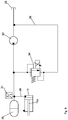
- FIGS. 8-10 represent schematic schematic diagrams for a hydraulic system according to the invention for adjusting the biasing force of the escape joint 10 to a minimum value.
- different hydraulic circuit diagrams are shown. It should be noted that other components of the hydraulic system may be present, but not shown for the simple schematic arrangement in the figures.
- Fig. 8 illustrates a hydraulic circuit diagram according to an embodiment of the invention for the pressurization of the actuator for changing the biasing force of the escape joint 10.
- the actuator is exemplified as a single-acting hydraulic cylinder 14 is formed.
- the hydraulic cylinder 14 is connected to the evasion joint 10 of the distributor linkage 2 in a manner not shown. Via the hydraulic line 38, the hydraulic cylinder 14 is connected to a hydraulic accumulator 30.
- the hydraulic accumulator 30 contains a hydraulic fluid.
- the pressure transmitter 31 provides an electrical transducer for measuring the existing pressure in Hydraulic cylinder 14, for example, can be closed on the basis of a sudden pressure peak in the hydraulic cylinder by the pressure transducer 31 on the collision with an obstacle. Then, the biasing force of the escape joint 10 can advantageously be reduced immediately.
- the hydraulic cylinder 14 is further connected via a pressure relief valve 34 and an overflow line 39 to a pump 32.
- the pump 32 is connected to a tank 33 for fluid supply, in particular for oil supply.
- a tank 33 for fluid supply, in particular for oil supply.
- other pressure relief valves not shown here can be installed.
- the pump or the oil supply can be arranged on the field sprayer or provided by the towing vehicle of the field sprayer.
- the pressure limiting valve 34 is electronically controllable and proportionally adjustable.
- the electronically controllable pressure relief valve 34 can advantageously be controlled via a data processing unit 5.
- the pressure relief valve 34 is connected via a control line, not shown, with the data processing unit 5.
- the data processing unit 5 Based on the measurement signals of the pressure transducer 31 or of further sensors arranged on the agricultural utility vehicle and / or distributor linkage, the data processing unit 5 generate a variable control signal. This means that the minimum necessary pressure on the hydraulic cylinder 14 can be set via the data processing unit 5.
- the pressure limiting valve 34 is driven in such a way, or the pressure value at the valve is adjusted such that a minimum value for the biasing force of the escape joint 10 is set.
- hydraulic fluid can flow via the pressure-limiting valve 34 via the overflow line 39 into the hydraulic cylinder 14 and displace the piston rod 14a.
- the maximum allowable pressure can be adjusted via the pressure limiting valve 34 in order to protect the hydraulic system against excessive pressure. If the pressure in the hydraulic system exceeds a limit value, the pressure-limiting valve 34 causes a drain of the hydraulic fluid to the tank 33.
- Fig. 9 illustrates another embodiment of a hydraulic circuit diagram according to Fig. 8 dar.
- a pressure regulating valve 35 is arranged in the overflow line 39.
- the pressure control valve 35 is electronically controllable and proportionally adjustable. Based on the measurement signals of the pressure transmitter 31 or of further sensors arranged on the agricultural utility vehicle and / or distributor linkage, the data processing unit 5 can generate a control signal for the pressure regulating valve 35, so that the valve is brought into such a setting that hydraulic fluid for pressure adjustment of the hydraulic cylinder 14 the overcurrent line 39 can flow over.
- the pressure control valve has in this case compared to in Fig. 8 used pressure relief valve has the advantage that not a continuous flow of fluid must be maintained, but only as much fluid is conveyed until the desired pressure is set.
- Fig. 10 shows a further embodiment of a hydraulic circuit diagram according to Fig. 8 , Compared to Fig. 8
- an additional check valve 36 and a pressure reducing valve 37 are arranged.
- the check valve 36 and the pressure reducing valve 37 are located between the hydraulic cylinder 14 and the pump 32 for fluid supply.
- a minimum pressure on the hydraulic cylinder 14 can be set by means of the pressure reducing valve 37. Should the minimum pressure be undershot, fluid flows from the pump into the hydraulic line 38 and thus into the hydraulic cylinder 14 for pressure equalization.
- the pressure limiting valve 34 By means of the pressure limiting valve 34, a maximum pressure on the hydraulic cylinder 14 can be adjusted.
- the in Fig. 10 shown hydraulic accumulator 30 also fulfills the purpose of a spring element, so that at smaller pressure fluctuations they can be collected via the hydraulic accumulator and opens the pressure relief valve 34 only with large pressure changes.
- the size of the hydraulic accumulator 30 can be selected in particular according to the desired spring action.
- the present invention and embodiments relate primarily to a hydraulic system, but can be transferred with equal effect on a pneumatic system.
Landscapes
- Life Sciences & Earth Sciences (AREA)
- Engineering & Computer Science (AREA)
- Insects & Arthropods (AREA)
- Pest Control & Pesticides (AREA)
- Wood Science & Technology (AREA)
- Zoology (AREA)
- Environmental Sciences (AREA)
- Catching Or Destruction (AREA)
- Agricultural Machines (AREA)
Abstract
Die Erfindung betrifft ein Steuersystem, welches ein Verteilergestänge (2) für ein landwirtschaftliches Nutzfahrzeug (1) zum Ausbringen von Material, wie Düngemittel, Pflanzenschutzmittel oder Saatgut, wenigstens ein Mittel zur direkten oder indirekten Erfassung von verschiedenen Betriebszuständen und/oder Umwelteinflüssen und eine Datenverarbeitungseinheit (5) zur Verarbeitung der Signale des wenigstens einen Mittels und zur Generierung eines Stellsignals für ein Stellorgan umfasst. Das Verteilergestänge (2) weist hierzu mehrere zueinander in Transportstellung einklappbare und in Arbeitsstellung ausklappbare, durch Schwenkgelenke verbundene Gestängeabschnitte (6) und ein Ausweichgelenk (10) an jeweils einem Endabschnitt (11) des Verteilergestänges (2) auf. Weiterhin ist die Vorspannkraft des Ausweichgelenks (10) mittels des Stellorgans je nach Betriebszustand und/oder Umwelteinfluss veränderbar auf einen Minimalwert einstellbar ist, bei dem das Ausweichgelenk (10) in seiner Arbeitsstellung gehalten ist. Weiterhin betrifft die Erfindung ein landwirtschaftliches Nutzfahrzeug (1) und ein Verfahren zur Steuerung eines landwirtschaftlichen Nutzfahrzeuges (1).The invention relates to a control system comprising a distributor linkage (2) for an agricultural utility vehicle (1) for discharging material such as fertilizers, pesticides or seeds, at least one means for directly or indirectly detecting different operating conditions and / or environmental influences and a data processing unit ( 5) for processing the signals of the at least one means and for generating an actuating signal for an actuator. For this purpose, the distributor linkage (2) has a plurality of linkage sections (6) which can be folded into the transport position and folded out in the working position, connected by swivel joints, and an escape joint (10) on each end section (11) of the distributor linkage (2). Furthermore, the biasing force of the escape joint (10) by means of the actuator depending on the operating condition and / or environmental influence is changeable to a minimum value adjustable in which the escape joint (10) is held in its working position. Furthermore, the invention relates to an agricultural utility vehicle (1) and a method for controlling an agricultural utility vehicle (1).
Description
Die Erfindung betrifft ein Steuersystem für ein landwirtschaftliches Nutzfahrzeug gemäß dem Oberbegriff des Patentanspruchs 1. Ferner betrifft die Erfindung ein landwirtschaftliches Nutzfahrzeug gemäß Anspruch 13, sowie ein Verfahren zur Steuerung eines landwirtschaftlichen Nutzfahrzeuges gemäß Anspruch 14.The invention relates to a control system for an agricultural utility vehicle according to the preamble of claim 1. Furthermore, the invention relates to an agricultural utility vehicle according to
Derartige Steuersysteme werden für landwirtschaftliche Nutzfahrzeuge zum Ausbringen von Material, wie Düngemittel, Pflanzenschutzmittel oder Saatgut verwendet. Um das Material großflächig und effizient auf dem zu bearbeitenden Feld auszubringen, weisen die landwirtschaftlichen Nutzfahrzeuge ein Verteilergestänge mit mehreren Sprühdüsen auf. Das Verteilergestänge erstreckt sich quer zur Fahrtrichtung und kann Arbeitsbreiten von bis zu 40m aufweisen. Die Sprühdüsen, welche in regelmäßigem Abstand am Verteilergestänge angebracht sind, dienen der Ausbringung des Materials auf das zu bearbeitende Feld. Dabei soll der Abstand zwischen dem Verteilergestänge und dem Boden oder der Oberkante des Pflanzenbestandes über die gesamte Arbeitsbreite des Verteilergestänges möglichst konstant bleiben. Das bedeutet, dass das Verteilergestänge möglichst parallel zum bearbeitenden Boden gehalten wird.Such control systems are used for agricultural vehicles to disperse material such as fertilizers, pesticides or seeds. To spread the material over a large area and efficiently on the field to be processed, the agricultural vehicles have a distributor linkage with several spray nozzles. The distribution link extends transversely to the direction of travel and can have working widths of up to 40m. The spray nozzles, which are mounted at a regular distance on the distributor linkage, serve to apply the material to the field to be processed. The distance between the distribution linkage and the soil or the upper edge of the crop is to remain as constant as possible over the entire working width of the distribution linkage. This means that the distribution linkage is kept as parallel as possible to the working soil.
Bekanntermaßen weist das Verteilergestänge mehrere Gestängeabschnitte auf, welche klappbar ausgebildet sind, damit das Verteilergestänge von einer platzsparenden Transportstellung in eine Arbeitsstellung mit der vollen Arbeitsbreite überführt werden kann. Die Transportstellung beschreibt hierbei den eingeklappten Zustand des Verteilergestänges. Im Gegensatz dazu beschreibt die Arbeitsstellung jenen Zustand des Verteilergestänges, bei dem alle Gestängeabschnitte ausgeklappt sind. Mit anderen Worten weist das Verteilergestänge in der Arbeitsstellung die gesamte Arbeitsbreite auf und befindet sich in einer vollständigen horizontalen Ausgangslage parallel zum Boden. Das Verteilergestänge kann vorzugsweise an einem mittig gelegenen Rahmen befestigt sein und hierdurch mit dem landwirtschaftlichen Nutzfahrzeug verbunden sein. Es sind generell symmetrische oder asymmetrische Aufhängungen des Verteilergestänges am Rahmen möglich.As is known, the distribution linkage has a plurality of linkage sections, which are foldable, so that the distribution linkage can be transferred from a space-saving transport position into a working position with the full working width. The transport position here describes the folded state of the distributor linkage. In contrast, the working position describes that state of the distributor linkage, in which all linkage sections are unfolded. In other words, the distribution linkage in the working position on the entire working width and is located in a complete horizontal starting position parallel to the ground. The distribution linkage can preferably be attached to a centrally located frame and thereby be connected to the agricultural utility vehicle. It is generally symmetrical or asymmetrical suspensions of the manifold linkage on the frame possible.
Im Rahmen der vorliegenden Anmeldung wird der Endabschnitt des Verteilergestänges als jener Abschnitt definiert, der bei voller Arbeitsbreite, oder anders gesagt bei einem vollständig ausgeklappten Verteilergestänge, sich außenseitig am Verteilergestänge befindet und mit dem innenseitig benachbarten Gestängeabschnitt über ein Ausweichgelenk, insbesondere ein Schwenkgelenk, verbunden ist. Mit anderen Worten beschreibt der Endabschnitt die nach außen hin freiliegende Spitze des Verteilergestänges. Es werden hierbei mit dem Ausweichgelenk und dem Endabschnitt und zugehörigen Stellorgan gleichermaßen jene Elemente des rechtsseitigen und linksseitigen äußeren Abschnitts des Verteilergestänges bezeichnet.In the context of the present application, the end section of the distributor linkage is defined as that section which at full working width, or in other words a fully deployed distributor linkage, is located on the outside of the distributor linkage and is connected to the inside adjacent linkage section via an evasion joint, in particular a pivot joint , In other words, the end portion describes the outwardly exposed tip of the manifold linkage. In this case, the elements corresponding to the right-sided and left-sided outer sections of the distributor linkage are referred to here with the avoidance joint and the end section and associated actuator.
Ein beispielhaftes Steuersystem für ein landwirtschaftliches Nutzfahrzeug ist aus der
Vorzugsweise am Rand des zu bearbeitenden Feldes kann es passieren, dass das Verteilergestänge auf ein Hindernis, wie beispielsweise einen Baum trifft. In diesem Fall muss der Endabschnitt des Verteilergestänges verschwenkt, beziehungsweise weggeklappt werden, damit er durch das Hindernis nicht beschädigt wird oder damit das landwirtschaftliche Nutzfahrzeug nicht durch ein Verlassen der Spur gezwungen ist, dem Hindernis direkt auszuweichen. Ein Verlassen der Spur würde eine unerwünschte Beschädigung des zu bearbeitenden Bodens oder des bereits gewachsenen Pflanzenbestandes zur Folge haben.Preferably, at the edge of the field to be processed, it may happen that the distribution linkage encounters an obstacle, such as a tree. In this case, the end portion of the distribution linkage must be pivoted or folded so that it is not damaged by the obstacle or so that the agricultural utility vehicle is not forced by leaving the track to avoid the obstacle directly. Leaving the Trace would result in undesirable damage to the soil to be worked or the plant stock already grown.
Der Endabschnitt des bekannten Verteilergestänges ist über ein bewegbares Ausweichgelenk am benachbart anliegenden Gestängeabschnitt befestigt und stellt einen Abbruchschutz dar. Dabei kann das Ausweichgelenk in Bezug auf die Fahrtrichtung in Vorwärts- und/oder Rückwärtsrichtung ausweichen.The end portion of the known distribution linkage is attached via a movable diverter link on adjoining linkage portion and provides a demolition protection. In this case, the avoidance joint with respect to the direction of travel in the forward and / or reverse direction can escape.
Mittels eines mechanischen Sensors kann das Auftreffen des Verteilergestänges auf ein Hindernis erfasst werden. Durch den mechanischen Sensor kann zusätzlich ein elektrischer Schalter betätigt werden, wodurch hydraulische Ventile zum Druckausgleich im Hydraulikzylindern angesteuert werden. Mit anderen Worten werden mittels der hydraulischen Ventile die Hydraulikzylinder zum Einklappen oder Ausklappen des Endabschnitts angesteuert. Da das bekannte Verteilergestänge zum vollständigen Einklappen des Endabschnitts ausgebildet ist, entsteht eine Zeitverzögerung, bis der eingeklappte Abschnitt wieder durch ein erneutes vollständiges Ausklappen zum Besprühen benutzt werden kann.By means of a mechanical sensor, the impact of the distribution linkage on an obstacle can be detected. In addition, an electrical switch can be actuated by the mechanical sensor, whereby hydraulic valves for pressure equalization in the hydraulic cylinders are activated. In other words, the hydraulic cylinders are actuated by means of the hydraulic valves for folding or unfolding of the end section. Since the known distribution linkage is formed to completely fold the end portion, there is a time delay until the collapsed portion can be reused for spraying again by completely unfolding it.
Weiterhin kann durch das vollständige Einklappen bei einem andauernden Betrieb der Sprühdüsen während des Einklappvorgangs eine inhomogene Materialverteilung auf dem zu bearbeitenden Feld entstehen.Furthermore, due to the complete collapse during continuous operation of the spray nozzles during the folding process, an inhomogeneous material distribution on the field to be processed can arise.
Der Erfindung liegt daher die Aufgabe zugrunde, eine variable Steuerung des Endabschnitts eines Verteilergestänges anzugeben. Der Erfindung liegt ferner die Aufgabe zu Grunde, ein landwirtschaftliches Nutzfahrzeug sowie ein Verfahren zur Steuerung eines landwirtschaftlichen Nutzfahrzeuges anzugeben.The invention is therefore based on the object to provide a variable control of the end portion of a manifold linkage. The invention is also based on the object of specifying an agricultural utility vehicle and a method for controlling an agricultural utility vehicle.
Diese Aufgabe wird erfindungsgemäß durch ein Steuersystem mit den Merkmalen des Anspruchs 1 gelöst. Im Hinblick auf das landwirtschaftliche Nutzfahrzeug wird die Aufgabe durch den Gegenstand des Anspruchs 13 gelöst. Ferner wird die Aufgabe im Hinblick auf das Verfahren durch den Gegenstand des Anspruchs 14 gelöst.This object is achieved by a control system with the features of claim 1. With regard to the agricultural utility vehicle, the object is achieved by the subject matter of
Die Erfindung beruht auf dem Gedanken, ein Steuersystem anzugeben, welches ein Verteilergestänge für ein landwirtschaftliches Nutzfahrzeug zum Ausbringen von Material, wie Düngemittel, Pflanzenschutzmittel oder Saatgut, wenigstens ein Mittel zur direkten oder indirekten Erfassung von verschiedenen Betriebszuständen und/oder Umwelteinflüssen und eine Datenverarbeitungseinheit zur Verarbeitung der Signale des wenigstens einen Mittels und zur Generierung eines Stellsignals für ein Stellorgan umfasst. Das Verteilergestänge weist hierzu mehrere zueinander in Transportstellung einklappbare und in Arbeitsstellung ausklappbare, durch Schwenkgelenke verbundene Gestängeabschnitte und ein Ausweichgelenk an jeweils einem Endabschnitt des Verteilergestänges auf. Weiterhin ist die Vorspannkraft des Ausweichgelenks mittels des Stellorgans je nach Betriebszustand und/oder Umwelteinfluss veränderbar auf einen Minimalwert einstellbar, bei dem das Ausweichgelenk in seiner Arbeitsstellung gehalten ist.The invention is based on the idea to provide a control system comprising a distributor linkage for an agricultural utility vehicle for delivering material such as fertilizers, pesticides or seeds, at least one means for directly or indirectly detecting various operating conditions and / or environmental influences and a data processing unit for processing the signals of the at least one means and for generating an actuating signal for an actuator comprises. For this purpose, the distributor linkage has a plurality of linkage sections, which can be folded into one another in the transport position and can be folded out in the working position, connected by swivel joints, and an evacuation joint on one end section of the distributor linkage. Furthermore, the biasing force of the escape joint by means of the actuator depending on the operating condition and / or environmental influence is changeably adjustable to a minimum value at which the escape joint is held in its working position.
Generell ist hierbei vorgesehen, dass das Ausweichgelenk und damit auch der Endabschnitt des Verteilergestänges bei Bedarf in eine auf die Fahrtrichtung bezogene Vorwärts- und/oder Rückwärtsrichtung oder auch in vertikaler Richtung ausweichen und/oder verschwenkt werden kann. Die Verstellung erfolgt hierbei über das Stellorgan, welches vorzugsweise als Aktor ausgebildet ist, der die Einstellung einer straffen oder lockeren Stellung des Ausweichgelenks ermöglicht. Hierzu wird über den Aktor das Stellsignal der Datenverarbeitungseinheit in mechanische Bewegung umgewandelt.In general, it is provided here that the avoidance joint and thus also the end section of the distributor linkage can, if necessary, be deflected and / or swiveled in a forward and / or reverse direction or also in a vertical direction relative to the direction of travel. The adjustment takes place here via the actuator, which is preferably designed as an actuator that allows the setting of a taut or loose position of the escape joint. For this purpose, the actuating signal of the data processing unit is converted into mechanical movement via the actuator.
Die Erfindung hat den Vorteil, dass die notwendige Vorspannkraft des Ausweichgelenks möglichst gering gehalten werden kann, und gleichzeitig im ungestörten Betrieb des landwirtschaftlichen Nutzfahrzeuges das Ausweichgelenk und damit der Endabschnitt möglichst starr mit dem Verteilergestänge verbunden sein kann. Die Vorspannkraft beschreibt hierbei die Haltekraft des Ausweichgelenks. Anders gesagt bezeichnet die Vorspannkraft jene Kraft, welche das Ausweichgelenk und damit auch den Endabschnitt mit dem restlichen Teil des Verteilergestänges verbindet und in der Arbeitsstellung hält. Erfindungsgemäß sollen die Kräfte auf das Ausweichgelenk und generell auf das Verteilergestänge möglichst gering gehalten werden, sodass Beschädigungen effizient verhindert werden können. Ebenso können Situationen, in denen das Ausweichgelenk zu starr oder zu lose mit dem Verteilergestänge verbunden ist, vermieden werden, sodass der Endabschnitt des Verteilergestänges optimal gehalten wird.The invention has the advantage that the necessary biasing force of the escape joint can be kept as low as possible, and at the same time in the undisturbed operation of the agricultural utility vehicle, the avoidance joint and thus the end portion can be connected as rigidly as possible with the manifold linkage. The preload force describes the holding force of the evasion joint. In other words, the biasing force refers to that force which connects the escape joint and thus also the end portion with the remaining part of the distributor linkage and holds in the working position. According to the invention, the forces on the avoidance joint and generally on the distributor bar should be kept as low as possible, so that damage can be effectively prevented. Also, situations in which the escape joint is too rigid or too loosely connected to the manifold linkage can be avoided so that the end portion of the manifold linkage is optimally held.
Im Vergleich zum bekannten Verteilergestänge gemäß dem Stand der Technik kann eine Situation vermieden werden, bei der die Vorspannkraft im Betrieb des landwirtschaftlichen Nutzfahrzeuges auf dem zu bearbeitenden Feld einen Wert von Null annimmt, so dass der Endabschnitt komplett eingeklappt wird und nicht mehr in der Transportstellung gehalten wird. Erfindungsgemäß ist vorgesehen, dass das Ausweichgelenk mittels des Stellorgans aktiv und kontinuierlich in der Arbeitsstellung gehalten und die notwendige Minimalkraft zum Vorspannen variiert und dauerhaft aufrechterhalten wird.In comparison to the known distributor linkage according to the prior art, a situation can be avoided in which the biasing force in the operation of the agricultural utility vehicle on the field to be processed assumes a value of zero, so that the end portion is completely folded and no longer held in the transport position becomes. According to the invention it is provided that the avoidance joint by means of the actuator actively and continuously held in the working position and varies the necessary minimum force for biasing and is permanently maintained.
Die Erfindung hat weiterhin den Vorteil, dass durch die Einstellung eines Minimalwertes der Vorspannkraft, dass Ausweichgelenk permanent in seiner Arbeitsstellung gehalten werden kann, beziehungsweise im Falle einer Auslenkung durch ein Hindernis schnellstmöglich in die Arbeitsstellung zurückgeführt werden kann. Hierdurch können die vorhandenen Sprühdüsen am Endabschnitt zur Ausbringung des Materials dauerhaft in Betrieb sein. Da der Endabschnitt beispielsweise bei einer Kollision nicht komplett eingeklappt wird, sondern durch die Vorspannkraft schnellstmöglich in die Arbeitsstellung zurückgebracht wird, sind mögliche Fehlapplikationen des auszubringenden Materials aus dem Sprühdüsen gering.The invention has the further advantage that by setting a minimum value of the biasing force that the alternate joint can be kept permanently in its working position, or in the case of a deflection by an obstacle as quickly as possible can be returned to the working position. As a result, the existing spray nozzles at the end portion for the application of the material can be permanently in operation. Since the end portion is not completely folded, for example in a collision, but by the biasing force As soon as possible in the working position is returned, possible misapplications of auszubringenden material from the spray nozzles are low.
Die Erfindung hat weiterhin den Vorteil, dass durch die vorhandenen Mittel zur direkten oder indirekten Erfassung von verschiedenen Betriebszuständen und/oder Umwelteinflüssen die Vorspannkraft des Ausweichgelenks sehr flexibel und variabel angepasst, beziehungsweise eingestellt werden kann. Dadurch kann bei jeglichen auftretenden Störgrößen die Vorspannkraft des Ausweichgelenks verstellt werden, damit das Ausweichgelenk und damit der Endabschnitt des Verteilergestänges in der Arbeitsstellung gehalten werden. Demnach können neben dem schwerwiegenden Fall einer Kollision mit einem Hindernis, auch vergleichbar weniger gravierende Vorfälle, wie beschleunigte oder verzögerte Bewegungen aufgrund von Bodenunebenheiten, kompensiert werden, wobei es nichtsdestotrotz für die effiziente Ausbringung des Materials vorteilhaft ist, das Verteilergestänge schnellstmöglich in seine Arbeitsstellung zurückzuführen.The invention also has the advantage that the pretensioning force of the evasion joint can be adjusted and / or adjusted very flexibly and variably by the existing means for direct or indirect detection of different operating states and / or environmental influences. Thereby, the biasing force of the escape joint can be adjusted for any disturbances that occur so that the avoidance joint and thus the end portion of the manifold linkage are held in the working position. Thus, in addition to the serious case of collision with an obstacle, comparatively less serious incidents such as accelerated or decelerated movements due to bumps can be compensated, nevertheless it is advantageous for the efficient application of the material to return the distributor linkage as quickly as possible to its working position.
Bevorzugte Ausführungsformen der Erfindung sind in den Unteransprüchen angegeben.Preferred embodiments of the invention are specified in the subclaims.
Bei einer bevorzugten Ausführungsform der Erfindung ist das wenigstens eine Mittel derart ausgebildet, dass sowohl Hindernisse, insbesondere die Position von Hindernissen, als auch die Bewegung des Verteilergestänges, insbesondere auftretende Beschleunigungen, erfassbar sind. Hierzu kann das Mittel vorzugsweise als Sensor, insbesondere als Bewegungssensor, ausgebildet sein. Es sind generell verschiedene Arten von Sensoren zur Erfassung eines Hindernisses oder zur Überwachung der Bewegungsart des Verteilergestänges denkbar. Im Speziellen kann der Sensor zur Geschwindigkeitsüberwachung ausgebildet sein, das heißt es wird ermittelt, ob das Verteilergestänge mit einer kontinuierlichen Geschwindigkeit bewegt wird, oder ob eine Beschleunigung oder Verzögerung vorliegt. Grundsätzliche Gesichtspunkte für die Sensorauswahl betreffen zweckmäßigerweise die dynamische Messgenauigkeit, eine geringe Trägheit des Sensors, und vorzugsweise eine hohe Messstabilität hinsichtlich Umweltbedingungen, wie beispielsweise Temperatur oder Feuchtigkeit.In a preferred embodiment of the invention, the at least one means is designed such that both obstacles, in particular the position of obstacles, as well as the movement of the distributor linkage, in particular occurring accelerations, are detectable. For this purpose, the means may preferably be designed as a sensor, in particular as a motion sensor. There are generally different types of sensors for detecting an obstacle or for monitoring the movement of the manifold linkage conceivable. Specifically, the sensor may be configured for speed monitoring, that is, it is determined whether the transfer linkage is being moved at a continuous rate or whether there is acceleration or deceleration. Basic aspects for the sensor selection relate expediently the dynamic measurement accuracy, a low inertia of the sensor, and preferably a high measurement stability with respect to environmental conditions, such as temperature or humidity.
Vorteilhafterweise ist die Vorspannkraft des jeweiligen Ausweichgelenks in Abhängigkeit von auftretenden Beschleunigungen des Verteilergestänges und/oder des landwirtschaftlichen Nutzfahrzeuges und/oder Erschütterungen aufgrund von Bodenunebenheiten und/oder Kurvenfahrten des landwirtschaftlichen Nutzfahrzeuges einstellbar. Weitere Möglichkeiten sind auftretenden Schwingungen oder Gierbewegungen des Verteilergestänges und/oder auftretenden Relativbewegungen des Ausweichgelenks zum starren Teil des Verteilergestänges und/oder einer Kollision mit einem Hindernis. Auch ist es denkbar die Vorspannkraft des Ausweichgelenks in Abhängigkeit von der aktuellen Fahrgeschwindigkeit und/oder der Aktivierung der Sprühdüsen veränderbar auf einen unterschiedlichen Minimalwert einzustellen. Damit kann eine große Vielfalt an möglichen Störfällen im Betrieb des Verteilergestänges auf dem zu bearbeitenden Feld umfasst werden, sodass das Ausweichgelenk nahezu zu jeder Zeit in seiner Arbeitsstellung gehalten werden kann und im Bedarfsfall schnellstmöglich und effizient zurückgeführt werden kann. Die Erfindung ist hierbei nicht auf die genannten unerwünschten Störfälle begrenzt, sondern auf jeglichen Betriebszustand und/oder Umwelteinfluss erweiterbar, in denen es von Vorteil ist, die Vorspannkraft des Ausweichgelenks anzupassen und auf einen anderen Minimalwert einzustellen. Anders gesagt sind auch weitere Störfälle denkbar, in denen es vorteilhaft ist, die Vorspannkraft des Ausweichgelenks zu lockern oder stärker einzustellen.Advantageously, the biasing force of the respective evasive joint is adjustable as a function of occurring accelerations of the distributor linkage and / or the agricultural utility vehicle and / or vibrations due to uneven ground and / or cornering of the agricultural utility vehicle. Further possibilities are occurring oscillations or yaw motions of the distributor linkage and / or occurring relative movements of the escape joint to the rigid part of the distributor linkage and / or a collision with an obstacle. It is also conceivable to adjust the pretensioning force of the evasive joint to a different minimum value as a function of the current driving speed and / or the activation of the spray nozzles. This can be a wide variety of possible incidents in the operation of the manifold linkage on the field to be processed are included, so that the evasive joint can be kept almost at all times in its working position and can be returned as needed as quickly and efficiently. The invention is not limited to the mentioned undesirable incidents, but extendable to any operating condition and / or environmental influence, in which it is advantageous to adjust the biasing force of the escape joint and set to a different minimum value. In other words, other incidents are conceivable in which it is advantageous to loosen the biasing force of the escape joint or adjust more.
Vorzugsweise ist das wenigstens eine Mittel durch einen Drehratensensor oder einen Beschleunigungssensor oder einen Dehnungsmesstreifen zur Ermittlung einer Belastungsänderung des Ausweichgelenks gebildet. Beispielsweise kann über den Sensor erfasst werden, ob sich der Endabschnitt des Verteilergestänges über das Ausweichgelenk bewegt. Hierbei wäre auch eine Erfassung der Bewegungsstärke oder der Amplituden denkbar. Werden kontinuierliche Bewegungen im Ausweichgelenk von dem Sensor registriert, erhöht das Steuersystem so lange die Vorspannkraft des Ausweichgelenks bis keine Bewegungen bei einer normalen Feldfahrt mehr detektiert werden oder ein festgelegter Maximalwert erreicht wurde. Werden keine Bewegungen im Ausweichgelenk registriert, kann die Vorspannkraft so lange reduziert werden, bis vereinzelte geringe Bewegungen am Außenausleger bei einer normalen Fahrt registriert werden.Preferably, the at least one means is formed by a yaw rate sensor or an acceleration sensor or a strain gauge for determining a load change of the escape joint. For example, it can be detected via the sensor whether the end section of the distributor linkage moves over the avoidance joint. This would include a detection of the strength of movement or the amplitudes conceivable. If continuous movements in the avoidance joint are registered by the sensor, the control system increases the prestressing force of the evasion joint until no movements during normal field travel are detected or a defined maximum value has been reached. If no movements are registered in the avoidance joint, the preload force can be reduced until isolated minor movements on the outrigger are registered during normal driving.
Weiterhin kann durch eine Ermittlung der Drehrate des Nutzfahrzeuges um die vertikale Achse und/oder der Geschwindigkeitsänderung erfasst werden, ob sich das landwirtschaftliche Nutzfahrzeug in einer Kurvenfahrt befindet. Das Mittel kann hierbei vorteilhafterweise am Verteilergestänge und/oder am landwirtschaftlichen Nutzfahrzeug positioniert sein. In Abhängigkeit von auftretenden Beschleunigungen und dem zugehörigen Betriebszustand des landwirtschaftlichen Nutzfahrzeuges kann die Vorspannkraft des Ausweichgelenks über die Datenverarbeitungseinheit und das zugehörige Stellorgan variiert werden, sodass das Ausweichgelenk weicher oder härter vorgespannt werden kann. Darüber hinaus ist es mittels Beschleunigungssensoren am Verteilergestänge möglich, Schwingungen des Endabschnitts zu erfassen. Diese Schwingungen können beispielsweise von Unebenheiten auf dem zu bearbeitenden Feld oder Spurrillen resultieren. Durch auftretende Schwingungen des Verteilergestänges und des Endabschnitts kann keine homogene Materialausbringung garantiert werden. Deshalb ist es besonders von Vorteil, im Falle einer zu starken Relativbewegung des Ausweichgelenks und des Endabschnitts im Vergleich zum restlichen Verteilergestänge, den Minimalwert der Vorspannkraft des Ausweichgelenks anzupassen, insbesondere zu erhöhen, damit das Ausweichgelenk gleichbleibend in der Arbeitsstellung gehalten wird.Furthermore, it can be detected by determining the rate of rotation of the commercial vehicle about the vertical axis and / or the speed change, whether the agricultural utility vehicle is cornering. The agent may advantageously be positioned on the distribution linkage and / or on the agricultural utility vehicle. Depending on occurring accelerations and the associated operating state of the agricultural utility vehicle, the biasing force of the escape joint can be varied via the data processing unit and the associated actuator, so that the avoidance joint can be biased softer or harder. In addition, it is possible by means of acceleration sensors on the distributor linkage to detect vibrations of the end section. These vibrations can result, for example, from unevenness on the field to be worked or ruts. By occurring vibrations of the distributor linkage and the end section no homogeneous material application can be guaranteed. Therefore, it is particularly advantageous in case of too strong relative movement of the escape joint and the end portion compared to the rest of the distribution linkage to adjust the minimum value of the biasing force of the escape joint, in particular to increase, so that the avoidance joint is kept constant in the working position.
Weiter vorzugsweise ist das wenigstens eine Mittel durch einen GPS-Sensor oder einen akustischen oder optischen Sensor zur Ermittlung der Position von Hindernissen gebildet. Dies hat den Vorteil, dass Hindernisse, wie beispielsweise Bäume in der Nähe oder am Rand des zu bearbeitenden Feldes, frühzeitig erkannt werden können und damit vorrausschauend die Vorspannkraft des Ausweichgelenks angepasst werden kann. Im Falle einer unvermeidbaren Kollision mit einem Hindernis kann die Vorspannkraft frühzeitig derart reduziert werden, so dass das Ausweichgelenk mit einer minimalen Vorspannkraft gehalten wird, um schnellstmöglich nach der Kollision wieder in die Arbeitsstellung zurückgeführt werden zu können. Demnach kann anhand von GPS (Global Positioning System)-Daten des Sensors ermittelt werden, ob das Ausweichgelenk stärker vorgespannt werden muss, also die minimale Vorspannkraft erhöht werden sollte. Beispielsweise bei einer ersten Umrundung des zu bearbeitenden Feldes mit dem landwirtschaftlichen Nutzfahrzeug ist die Gefahr am größten, dass der Endabschnitt des Verteilergestänges an der Feldkante mit einem Objekt bzw. Hindernis kollidiert. Aus diesem Grund sollte die minimale Vorspannkraft des Ausweichgelenks bei der ersten Feldumrundung geringer gewählt werden, um Beschädigungen an dem Verteilergestänge zu verhindern. Des Weiteren können aufgrund der GPS-Daten vorteilhafterweise die Positionskoordinaten von möglich auftretenden Hindernissen in der Datenverarbeitungseinheit hinterlegt und gespeichert werden, wodurch die Früherkennung von Hindernissen weiter effizient verbessert werden kann.Further preferably, the at least one means is formed by a GPS sensor or an acoustic or optical sensor for determining the position of obstacles. This has the advantage that obstacles, such as trees near or at the edge of the field to be processed, can be detected early and thus anticipatory the biasing force of the evasive joint can be adjusted. In the event of an unavoidable collision with an obstacle, the biasing force can be reduced at an early stage so that the avoidance joint is held with a minimal preload force in order to be returned to the working position as soon as possible after the collision can. Thus, using GPS (Global Positioning System) data from the sensor, it can be determined if the evasive joint needs to be biased more, that is, the minimum preload force should be increased. For example, in a first orbit of the field to be processed with the agricultural utility vehicle, the greatest risk is that the end section of the distributor linkage collides with an object or obstacle at the field edge. For this reason, the minimum preload force of the evasion joint should be chosen to be smaller at the first field turn around to prevent damage to the manifold linkage. Furthermore, due to the GPS data, the position coordinates of possible obstacles can advantageously be stored and stored in the data processing unit, whereby the early detection of obstacles can be further efficiently improved.
In einer weiteren Ausführungsform ist das wenigstens eine Mittel derart ausgebildet, dass Prozessinformationen des Fahrzeugzustands, insbesondere der Betriebszustand der Sprühdüsen des Verteilergestänges, erfassbar sind. Hierbei kann das Mittel sehr einfach ausgestaltet sein, indem eine Steuereinheit in der Datenverarbeitungseinheit ermittelt, ob die Sprühdüsen, insbesondere die in dem oder den äußeren Segmenten des Verteilergestänges, aktiviert oder deaktiviert sind. Es ist in diesem Fall kein Sensor notwendig. Bei deaktivierten Sprühdüsen im Betrieb des landwirtschaftlichen Nutzfahrzeuges auf dem zu bearbeitenden Feld ist das Verhalten des Ausweichgelenks als weniger relevant im Vergleich zum Betrieb der Sprühdüsen anzusehen. Es ist bei deaktivierten Sprühdüsen davon auszugehen, dass das Ausweichgelenk auch aufgrund von minimalen Umwelteinflüssen oder Hinderniseinflüssen wegklappen kann. Demnach ist es vorteilhaft, die Vorspannkraft des Ausweichgelenks abhängig vom Betriebszustand der Sprühdüsen einzustellen. Hinsichtlich von weiteren Prozessinformationen des Fahrzeugzustandes ist es von Vorteil, die Vorspannung des Ausweichgelenks in Abhängigkeit von der Fahrtgeschwindigkeit des landwirtschaftlichen Nutzfahrzeuges veränderbar einzustellen. Im Falle eines frühzeitig erkannten Hindernisses wird in der Regel die Fahrtgeschwindigkeit vom Anwender reduziert, um sich dem Hindernis zur Vorbeugung von Schäden möglichst langsam zu nähern. Hierzu kann es von Vorteil sein, die Vorspannkraft des Ausweichgelenks ebenso auf einen veränderlichen Minimalwert zu reduzieren.In a further embodiment, the at least one means is designed such that process information of the vehicle state, in particular the operating state of the spray nozzles of the distributor linkage, can be detected. In this case, the means can be configured very simply by a control unit in the data processing unit determining whether the spray nozzles, in particular those in the one or more outer segments of the distributor linkage, are activated or deactivated. In this case, no sensor is necessary. When spray nozzles are deactivated during operation of the agricultural utility vehicle on the field to be processed, the behavior of the evasion joint is considered to be less relevant compared to the operation of the spray nozzles. With deactivated spray nozzles it can be assumed that the avoidance joint can also fold away due to minimal environmental influences or obstacles. Accordingly, it is advantageous to adjust the biasing force of the escape joint depending on the operating state of the spray nozzles. Regarding further process information Of the vehicle condition, it is advantageous to adjust the bias of the escape joint as a function of the travel speed of the agricultural utility vehicle changeable. In the case of an early detected obstacle, the speed of travel is usually reduced by the user in order to approach the obstacle for the prevention of damage as slowly as possible. For this purpose, it may be advantageous to reduce the biasing force of the escape joint also to a variable minimum value.
In einer bevorzugten Ausführungsform sind mehrere Mittel an verschiedenen Positionen am Verteilergestänge, insbesondere im angrenzenden Bereich an das jeweilige Ausweichgelenk, und/oder am landwirtschaftlichen Nutzfahrzeug positioniert. Die Mittel können generell unterschiedlich oder gleichartig ausgebildet sein. Weiterhin können die mehreren Mittel an unterschiedlichen Positionen am Verteilergestänge und/oder am landwirtschaftlichen Nutzfahrzeug positioniert sein. Es kann von besonderem Vorteil sein, dass die gleiche Anzahl an Mittel am rechtsseitigen und linksseitigen Abschnitt des Verteilergestänges positioniert ist. Die Anbringung von mehreren Mitteln hat generell den Vorteil, dass die Datenverarbeitungseinheit beispielsweise die Signale aller Mittel kombinieren kann, um bei Fehlmessungen oder dem Ausfall eines einzelnen Mittels, die Vorspannkraft des Ausweichgelenks möglichst genau einzustellen.In a preferred embodiment, a plurality of means are positioned at different positions on the distribution linkage, in particular in the adjacent area to the respective avoidance joint, and / or on the agricultural utility vehicle. The means may generally be different or similar. Furthermore, the plurality of means may be positioned at different positions on the distribution linkage and / or on the agricultural utility vehicle. It may be of particular advantage that the same number of means is positioned on the right-hand and left-hand sides of the distributor linkage. The provision of a plurality of means generally has the advantage that the data processing unit can, for example, combine the signals of all means in order to set the biasing force of the escape joint as precisely as possible in the event of incorrect measurements or the failure of a single agent.
Weiterhin kann anhand von plötzlich auftretenden Gierbewegungen des Verteilergestänges auf die Kollision mit einem Hindernis geschlossen werden. Hierzu ist es von besonderem Vorteil, wenn sowohl ein Mittel zur Erfassung der Drehbewegung am Verteilergestänge, als auch ein Mittel zur Erfassung von Gierbewegungen am landwirtschaftlichen Nutzfahrzeug positioniert ist. Dadurch kann ausgeschlossen werden, dass die ermittelten Gierbewegungen am Verteilergestänge nicht auf die Bewegungen des Nutzfahrzeuges zurückzuführen sind. Durch den Einsatz von mehreren Sensoren kann somit die Vorspannkraft des Ausweichgelenks optimal eingestellt werden.Furthermore, it can be concluded on the basis of sudden yaw movements of the distributor linkage on the collision with an obstacle. For this purpose, it is particularly advantageous if both a means for detecting the rotational movement of the distributor linkage, as well as a means for detecting yaw movements on the agricultural utility vehicle is positioned. As a result, it can be ruled out that the determined yawing movements on the distributor linkage are not due to the movements of the commercial vehicle. Through the use of multiple sensors can thus be optimally adjusted, the biasing force of the escape joint.
Vorteilhafterweise weist das Stellorgan ein Hydrauliksystem zur Veränderung der Vorspannkraft des Ausweichgelenks auf. Derartige Systeme bilden kostengünstige und einfache Mittel zur Einstellung der Vorspannkraft. Des Weiteren ermöglichen hydraulische Systeme eine sehr präzise und vor allem schnelle Stellgenauigkeit, wobei bei Bedarf auch sehr große Kräfte erzeugt werden können, um das Ausweichgelenk möglichst starr mit dem Verteilergestänge zu verbinden.Advantageously, the actuator on a hydraulic system for changing the biasing force of the escape joint. Such systems are inexpensive and simple means for adjusting the biasing force. Furthermore, hydraulic systems enable a very precise and above all fast positioning accuracy, whereby very large forces can be generated if necessary in order to connect the avoidance joint as rigidly as possible to the distributor linkage.
In einer besonders bevorzugten Ausführungsform umfasst das Hydrauliksystem einen Hydraulikzylinder, insbesondere einen einfachwirkenden Hydraulikzylinder, eine Hydraulikleitung, welche zur Zufuhr von Hydraulikflüssigkeit an den Hydraulikzylinder angeschlossen ist, und eine hydraulische Ventileinheit, insbesondere ein Druckregelventil, zur Regelung des Hydraulikdrucks, wobei die Ventileinheit über ein Stellsignal der Datenverarbeitungseinheit steuerbar ist. Die hydraulische Ventileinheit kann beispielhaft durch ein Druckregelventil, ein Druckbegrenzungsventil oder weitere Verschaltungen zur Verstellung bzw. Änderung des anliegenden Hydraulikdrucks umfassen. Insbesondere das Druckbegrenzungsventil hat den Vorteil eines sicheren und schnell wirkenden Überlastungsschutz des Hydraulikzylinders. Generell hat der Einsatz einer Hydraulikflüssigkeit den Vorteil, dass die Reibung im Stellorgan vermindert ist und gleichzeitig Korrosionsschutz gewährleistet werden kann. Das Stellorgan kann zweckmäßigerweise generell als Aktor ausgebildet sein, um die elektrischen Stellsignale der Datenverarbeitungseinheit in eine mechanische Bewegung umzuwandeln, welche die Vorspannkraft des Ausweichgelenks derart verändert, dass dieses in seiner Arbeitsstellung gehalten wird oder bei Bedarf schnellstmöglich in die Arbeitsstellung zurückgeführt wird.In a particularly preferred embodiment, the hydraulic system comprises a hydraulic cylinder, in particular a single-acting hydraulic cylinder, a hydraulic line which is connected to the hydraulic cylinder for supplying hydraulic fluid, and a hydraulic valve unit, in particular a pressure regulating valve, for regulating the hydraulic pressure, wherein the valve unit via a control signal the data processing unit is controllable. By way of example, the hydraulic valve unit may comprise a pressure regulating valve, a pressure limiting valve or further connections for adjusting or changing the applied hydraulic pressure. In particular, the pressure relief valve has the advantage of safe and fast-acting overload protection of the hydraulic cylinder. In general, the use of a hydraulic fluid has the advantage that the friction in the actuator is reduced and at the same time corrosion protection can be ensured. The actuator may conveniently be configured generally as an actuator to convert the electrical control signals of the data processing unit in a mechanical movement, which changes the biasing force of the escape joint such that it is held in its working position or if necessary returned to the working position as quickly as possible.
Weiter vorzugsweise steht die an dem jeweiligen Hydraulikzylinder angeschlossene Hydraulikleitung mit zumindest einem Hydraulikspeicher in Verbindung. Es ist denkbar, dass das Hydrauliksystem einen zentralen Hydraulikspeicher umfasst oder alternativ jeweils ein Hydraulikspeicher dem rechtsseitigen oder linksseitigen Ausweichgelenk des Verteilergestänges zugeordnet ist. Durch den Hydraulikspeieher wird vorteilhafterweise der in dem Hydraulikzylinder wirkende Hydraulikdruck zur Einstellung der Vorspannkraft des Ausweichgelenks erzeugt.Further preferably, the hydraulic line connected to the respective hydraulic cylinder communicates with at least one hydraulic accumulator. It is conceivable that the hydraulic system comprises a central hydraulic accumulator or, alternatively, in each case a hydraulic accumulator is assigned to the right-hand side or left-hand evasive joint of the distributor linkage. Through the hydraulic spreader Advantageously, the force acting in the hydraulic cylinder hydraulic pressure for adjusting the biasing force of the escape joint is generated.
Vorteilhafterweise ist hierbei das wenigstens eine Mittel durch einen Drucksensor, insbesondere einen Druckmessumformer, gebildet, welcher in der Hydraulikleitung angebracht ist. Beispielsweise kann anhand einer plötzlich auftretenden Druckspitze im Hydraulikzylinder auf die Kollision mit einem Hindernis geschlossen werden. Daraufhin kann die Vorspannkraft des Ausweichgelenks vorteilhafterweise unmittelbar reduziert und damit angepasst werden. Ebenso können auch Erschütterungen anhand von möglichen Druckschwankungen durch das Überfahren von Bodenunebenheiten mittels des Drucksensors erfasst und die Vorspannkraft dementsprechend angepasst werden.Advantageously, in this case the at least one means by a pressure sensor, in particular a pressure transducer, formed, which is mounted in the hydraulic line. For example, it can be concluded on the basis of a sudden pressure peak in the hydraulic cylinder on the collision with an obstacle. Thereupon, the biasing force of the escape joint advantageously can be reduced immediately and thus adapted. Likewise, vibrations can be detected by means of the pressure sensor based on possible pressure fluctuations by driving over bumps in the ground and the biasing force can be adjusted accordingly.
In einer weiteren Ausführungsform weist die Datenverarbeitungseinheit eine Betätigungsvorrichtung zur manuellen Generierung eines Stellsignals für das Stellorgan auf. Mit anderen Worten ist die Vorspannkraft mittels des Stellorgans basierend auf den Signalen des wenigstens einen Mittels manuell verstellbar. Es kann hierzu von besonderem Vorteil sein, wenn die Betätigungsvorrichtung als Knopf an der Datenverarbeitungseinheit ausgebildet ist. Dies ermöglicht dem Anwender des landwirtschaftlichen Nutzfahrzeuges die Vorspannkraft des Ausweichgelenks während des Fahrzeugbetriebs manuell und/oder automatisch nach Bedarf zu verstellen.In a further embodiment, the data processing unit has an actuating device for the manual generation of an actuating signal for the actuator. In other words, the biasing force is manually adjustable by means of the actuator based on the signals of the at least one agent. It may be of particular advantage for this purpose if the actuating device is designed as a button on the data processing unit. This allows the user of the agricultural utility vehicle to manually and / or automatically adjust the biasing force of the evasive joint during vehicle operation as needed.
Im Rahmen der vorliegenden Anmeldung wird weiterhin ein landwirtschaftliches Nutzfahrzeug zum Ausbringen von Material, wie Düngemittel, Pflanzenschutzmittel oder Saatgut mit einem Steuersystem nach einem der vorhergehenden Ausführungsformen beansprucht.In the context of the present application, furthermore, an agricultural utility vehicle for applying material, such as fertilizers, pesticides or seeds, with a control system according to one of the preceding embodiments is claimed.
Weiterhin wird im Rahmen der vorliegenden Anmeldung ein Verfahren zur Steuerung eines landwirtschaftlichen Nutzfahrzeuges offenbart, wobei das landwirtschaftliche Nutzfahrzeug ein Verteilergestänge zum Ausbringen von Material, wie Düngemittel, Pflanzenschutzmittel oder Saatgut, wenigstens ein Mittel zur direkten oder indirekten Erfassung von verschiedenen Betriebszuständen und/oder Umwelteinflüssen und eine Datenverarbeitungseinheit zur Verarbeitung der Signale des wenigstens einen Mittels und zur Generierung eines Stellsignals für ein Stellorgan umfasst. Das Verteilergestänge weist mehrere zueinander in Transportstellung einklappbare und in Arbeitsstellung ausklappbare, durch Schwenkgelenke verbundene Gestängeabschnitte, und an jeweils einem Endabschnitt des Verteilergestänges ein Ausweichgelenk auf. Das Verfahren umfasst folgende Schritte:
- a) das wenigstens eine Mittel erfasst den Betriebszustand und/oder Umwelteinfluss des Verteilergestänges und/oder landwirtschaftlichen Nutzfahrzeuges;
- b) die Signale des wenigstens einen Mittels werden von der Datenverarbeitungseinheit verarbeitet;
- c) die Datenverarbeitungseinheit generiert ein Stellsignal basierend auf den Signalen des Mittels;
- d) mit Hilfe des Stellsignals wird das dem jeweiligen Ausweichgelenk zugeordnete Stellorgan angesteuert, sodass die Vorspannkraft des jeweiligen Ausweichgelenks auf einen Minimalwert eingestellt wird, bei dem das Ausweichgelenk in seiner Arbeitsstellung gehalten wird.
- a) the at least one means detects the operating state and / or environmental influence of the distributor linkage and / or agricultural utility vehicle;
- b) the signals of the at least one means are processed by the data processing unit;
- c) the data processing unit generates a control signal based on the signals of the means;
- d) with the aid of the actuating signal, the actuator assigned to the respective avoidance joint is activated, so that the biasing force of the respective escape joint is set to a minimum value at which the avoidance joint is held in its working position.
In einer weiteren Ausführungsform wird die Vorspannkraft des Ausweichgelenks in Abhängigkeit von auftretenden Beschleunigungen des Verteilergestänges und/oder des landwirtschaftlichen Nutzfahrzeuges und/oder Erschütterungen aufgrund von Bodenunebenheiten und/oder Kurvenfahrten des landwirtschaftlichen Nutzfahrzeuges und/oder auftretenden Schwingungen oder Gierbewegungen des Verteilergestänges und/oder auftretenden Relativbewegungen des Ausweichgelenks zum starren Teil des Verteilergestänges und/oder einer Kollision mit einem Hindernis und/oder der aktuellen Fahrgeschwindigkeit und/oder der Aktivierung der Sprühdüsen auf einen unterschiedlichen Minimalwert eingestellt.In a further embodiment, the biasing force of the evasion joint is dependent on occurring accelerations of the distributor linkage and / or the agricultural utility vehicle and / or vibrations due to uneven ground and / or cornering of the agricultural utility vehicle and / or vibrations occurring or yawing the distributor linkage and / or relative movements of the escape joint to the rigid part of the distributor linkage and / or a collision with an obstacle and / or the current travel speed and / or the activation of the spray nozzles set to a different minimum value.
Weiter vorzugsweise wird die Vorspannkraft des Ausweichgelenks des Verteilergestänges im Bedarfsfall manuell mittels einer Betätigungsvorrichtung der Datenverarbeitungseinheit mittels des Stellorgans verändert.Further preferably, the biasing force of the escape joint of the distributor linkage is changed manually if necessary by means of an actuating device of the data processing unit by means of the actuator.
Zu den Vorteilen des Verfahrens zur Steuerung eines landwirtschaftlichen Nutzfahrzeuges wird auf die im Zusammenhang mit dem Steuersystem erläuterten Vorteile verwiesen.For the advantages of the method for controlling an agricultural utility vehicle, reference is made to the advantages explained in connection with the control system.
Die Erfindung wird nachstehend mit weiteren Einzelheiten unter Bezug auf die beigefügten schematischen Zeichnungen näher erläutert. Darin zeigen
- Fig. 1
- eine Seitenansicht eines landwirtschaftlichen Nutzfahrzeuges mit einem Verteilergestänge und einem Steuersystem nach einem erfindungsgemäßen Ausführungsbeispiel;
- Fig. 2
- eine Rückansicht des landwirtschaftlichen Nutzfahrzeuges gemäß
Fig. 1 mit einem Steuersystem nach einem erfindungsgemäßen Ausführungsbeispiel bei deaktivierten Sprühdüsen; - Fig. 3
- eine Rückansicht des landwirtschaftlichen Nutzfahrzeuges gemäß
Fig. 2 bei aktivierten Sprühdüsen; - Fig. 4
- eine Frontalansicht des rechtsseitigen Ausweichgelenks zwischen dem Endabschnitt und dem benachbarten innen angrenzenden Gestängeabschnitt nach einem weiteren erfindungsgemäßen Ausführungsbeispiel;
- Fig. 5
- eine perspektivische Ansicht des Ausweichgelenks gemäß
Fig. 4 ; - Fig. 6
- eine Frontalansicht des Ausweichgelenks gemäß
Fig. 4 , wobei der Endabschnitt des Verteilergestänges sich in einer nach oben gerichteten Ausweichposition befindet; - Fig. 7
- eine perspektivische Ansicht des Ausweichgelenks gemäß
Fig. 6 ; - Fig. 8
- eine schematische Prinzipdarstellung eines Hydraulikschaltplans für ein erfindungsgemäßes Steuersystem zur Einstellung der Vorspannkraft des Ausweichgelenks auf einen Minimalwert;
- Fig. 9
- eine weitere schematische Prinzipdarstellung eines Hydraulikschaltplans für ein erfindungsgemäßes Steuersystem;
- Fig. 10
- eine dritte schematische Prinzipdarstellung eines Hydraulikschaltplans für ein erfindungsgemäßes Steuersystem.
- Fig. 1
- a side view of an agricultural utility vehicle with a distributor linkage and a control system according to an embodiment of the invention;
- Fig. 2
- a rear view of the agricultural vehicle according to
Fig. 1 with a control system according to an embodiment of the invention with deactivated spray nozzles; - Fig. 3
- a rear view of the agricultural vehicle according to
Fig. 2 with activated spray nozzles; - Fig. 4
- a frontal view of the right-side escape joint between the end portion and the adjacent inner adjacent linkage portion according to a further embodiment of the invention;
- Fig. 5
- a perspective view of the escape joint according to
Fig. 4 ; - Fig. 6
- a frontal view of the escape joint according to
Fig. 4 wherein the end portion of the manifold linkage is in an upward deflection position; - Fig. 7
- a perspective view of the escape joint according to
Fig. 6 ; - Fig. 8
- a schematic schematic diagram of a hydraulic circuit diagram for a control system according to the invention for adjusting the biasing force of the escape joint to a minimum value;
- Fig. 9
- a further schematic diagram of a hydraulic circuit diagram for a control system according to the invention;
- Fig. 10
- a third schematic diagram of a hydraulic circuit diagram for a control system according to the invention.
Über ein dem nicht dargestellten Ausweichgelenk 10 am Verteilergestänge 2 zugeordnetes Stellorgan kann die Vorspannkraft des Ausweichgelenks 10 je nach Betriebszustand und/oder Umwelteinfluss veränderbar auf einen Minimalwert eingestellt werden. Dadurch kann das Ausweichgelenk 10 und damit der Endabschnitt 11 des Verteilergestänges 2 möglichst starr und gleichzeitig mit geringstem Kraftaufwand in der Arbeitsstellung gehalten werden. Vorzugsweise in der Arbeitsstellung, oder anders gesagt bei einem vollständig ausgeklappten Verteilergestänge 2, sind die an einer Unterkante des Verteilergestänges 2 angebrachten Sprühdüsen 4 aktiviert, um das auszubringende Material auf das zu bearbeitende Feld zu sprühen.About a
Die drei Sensoren 3 sind beispielhaft an einer Unterkante des Antriebsfahrzeuges 1a, an einem Rad des Anhängers 1b und am Verteilergestänge 2 positioniert. Die Sensoren 3 können als Drehraten- und/oder Beschleunigungssensoren ausgebildet sein. Es können beispielhaft auftretende Beschleunigungen anhand von einer Kurvenfahrt oder Bodenunebenheiten erfasst werden. Durch die Positionierung der Sensoren 3 am Verteilergestänge 2 und am Nutzfahrzeug 1 können die Bewegungen des Verteilergestänges 2 von jenen Bewegungen des Fahrzeugs 1 entkoppelt werden. Demnach kann, basierend auf den Messsignalen der Sensoren 3, die Datenverarbeitungseinheit 5 präzise und effizient ein Stellsignal für das zugehörige Stellorgan des Ausweichgelenks 10 generieren, um das jeweilige Ausweichgelenk 10 stärker oder lockerer vorzuspannen. Anders gesagt wird hierbei der Minimalwert der Vorspannkraft des jeweiligen Ausweichgelenks 10 angepasst und je nach Störfeinfluss veränderlich auf einen Minimalwert eingestellt.The three
Die
Jeweils am rechtsseitigen und linksseitigen Ende des Verteilergestänges 2 ist ein Endabschnitt 11 angebracht. Der Endabschnitt 11 ist über ein Ausweichgelenk 10 mit dem benachbarten innenliegenden Gestängeabschnitt 6 verbunden. Der Endabschnitt 11 weist wie die anderen Gestängeabschnitte 6 Sprühdüsen 4 auf.In each case at the right-side and left-side end of the
Durch die Einstellung eines Minimalwertes der Vorspannkraft, kann das Ausweichgelenk 10 und damit der Endabschnitt 11 permanent in seiner Arbeitsstellung gehalten werden, beziehungsweise im Falle einer Auslenkung durch eine Kollision mit einem Hindernis schnellstmöglich in die Arbeitsstellung zurückgebracht werden. Vorteilhafterweise können demnach die Sprühdüsen 4 des Endabschnitts 11 zur Ausbringung des Materials dauerhaft in Betrieb sein.By setting a minimum value of the biasing force, the avoidance joint 10 and thus the
Die
Das Ausweichgelenk 10 umfasst zwei übereinanderliegende Gelenkelemente 12, 13. Dabei ist das obere und untere Gelenkelement 12, 13 bewegbar beziehungsweise versetzbar, insbesondere kippbar, ausgebildet. Am Obergurt 21 des Endabschnitts 11 ist ein Hydraulikzylinder 14 angeordnet. Der Hydraulikzylinder 14 ist beispielhaft als einfachwirkender Hydraulikzylinder ausgebildet und erzeugt eine Vorspannkraft zwischen dem Endabschnitt 11 und dem Gestängeabschnitt 6. Mittels des Hydraulikzylinders 14 wird der Endabschnitt 11 gegenüber dem Gestängeabschnitt 6 ausweichbar gehalten. Im Speziellen wird durch die Datenverarbeitungseinheit 5 ein Stellsignal für den Hydraulikzylinder 14 generiert, sodass das Ausweichgelenk 10 auf einer minimalen Vorspannkraft gehalten wird.The avoidance joint 10 comprises two superimposed
Beispielhaft sind zwei Sensoren 3 am Ausweichgelenk 10 und am Hydraulikzylinder 14 positioniert. Dabei können die Sensoren 3 direkt oder indirekt eine Bewegung des Hydraulikzylinders 14 erfassen. Eine Bewegung des Hydraulikzylinders 14 ist hierzu mit einer Relativbewegung zwischen dem Gestängeabschnitt 6 und dem Endabschnitt 11 gleichzusetzen. Die Sensoren 3 können beispielhaft als Wegmesssystem oder Potentiometer oder Kontaktschalter ausgebildet sein.By way of example, two
Die
Beispielhaft ist der Fall gezeigt, dass der Endabschnitt 11 in Bodenberührung kommt, und deshalb zum Ausweichen nach oben gedrückt wird. Hierzu wird der Endabschnitt angehoben und schwenkt um eine Gelenkachse des Ausweichgelenks nach oben. Dabei bewegen sich die Gelenkelemente 12, 13 ebenfalls nach oben. Vorteilhafterweise kann mittels des Hydraulikzylinders 14 die Vorspannkraft des Ausweichgelenks 10 derart angepasst werden, damit das Ausweichgelenk 10 und damit auch der Endabschnitt 11 schnellstmöglich wieder in die Arbeitsstellung gemäß den
Die
Der Hydraulikzylinder 14 ist weiterhin über ein Druckbegrenzungsventil 34 und eine Überstromleitung 39 mit einer Pumpe 32 verbunden. Die Pumpe 32 ist an einem Tank 33 zur Fluid-Versorgung, insbesondere zur Öl-Versorgung, angeschlossen. Zur Pumpenabsicherung können weitere hier nicht dargestellte Druckbegrenzungsventile eingebaut werden. Die Pumpe bzw. die Ölversorgung kann an der Feldspritze angeordnet oder durch das Zugfahrzeug der Feldspritze bereitgestellt werden. Das Druckbegrenzungsventil 34 ist elektronisch steuerbar und proportional verstellbar.The
Sollte der Endabschnitt 11 des Verteilergestänges mit einem Hindernis kollidieren, weicht das Ausweichgelenk 10 und damit auch der Endabschnitt 11 dem Hindernis aus. Durch das Ausweichen wird eine Kolbenstange 14a des Hydraulikzylinders 14 verschoben und verdrängt dabei das hydraulische Fluid in den Hydraulikspeicher 30 und/oder über das Druckbegrenzungsventil 34 in die Überstromleitung 39. Nach der Kollision wird das unter Druck stehende hydraulische Fluid beispielhaft mittels des Druckbegrenzungsventils 34 in den Hydraulikzylinder 14 zurückgedrückt. Dabei wird die Kolbenstange 14a des Hydraulikzylinders verschoben, sodass das Ausweichgelenk 10 in die Arbeitsstellung zurückgeführt wird.Should the
Das elektronisch steuerbare Druckbegrenzungsventil 34 kann vorteilhafterweise über eine Datenverarbeitungseinheit 5 angesteuert werden. Dazu ist das Druckbegrenzungsventil 34 über eine nicht dargestellte Steuerleitung mit der Datenverarbeitungseinheit 5 verbunden. Basierend auf den Messsignalen des Druckmessumformers 31 oder von weiteren am landwirtschaftlichen Nutzfahrzeug und/oder Verteilergestänge angeordneten Sensoren kann die Datenverarbeitungseinheit 5 ein variables Steuersignal generieren. Das bedeutet, dass über die Datenverarbeitungseinheit 5 der minimal notwendige Druck am Hydraulikzylinder 14 eingestellt werden kann. Mittels des Signals wird das Druckbegrenzungsventil 34 derart angesteuert, beziehungsweise der Druckwert am Ventil derart angepasst, dass ein Minimalwert für die Vorspannkraft des Ausweichgelenks 10 eingestellt wird. Hierzu kann über das Druckbegrenzungsventil 34 hydraulisches Fluid über die Überstromleitung 39 in den Hydraulikzylinder 14 fließen und die Kolbenstange 14a verschieben. Weiterhin kann über das Druckbegrenzungsventil 34 der maximal zulässige Druck eingestellt werden, um das Hydrauliksystem gegen zu hohen Druck abzusichern. Übersteigt der Druck im Hydrauliksystem einen Grenzwert, bewirkt das Druckbegrenzungsventil 34 einen Abfluss des hydraulischen Fluids zum Tank 33.The electronically controllable
Die weitere Funktionsweise des Hydrauliksystems ist analog zu
Die vorliegende Erfindung und Ausführungsbeispiele beziehen sich vorrangig auf ein hydraulisches System, können jedoch mit gleicher Wirkung auch auf ein pneumatisches System übertragen werden.The present invention and embodiments relate primarily to a hydraulic system, but can be transferred with equal effect on a pneumatic system.
- 11
- landwirtschaftliches Nutzfahrzeugagricultural utility vehicle
- 1a1a
- Antriebsfahrzeugdrive vehicle
- 1b1b
- Anhängerpendant
- 22
- Verteilergestängedistributor tube assembly
- 33
- Sensorsensor
- 44
- Sprühdüsespray nozzle
- 55
- DatenverarbeitungseinheitData processing unit
- 66
- Gestängeabschnittboom section
- 1010
- Ausweichgelenkdodge joint
- 1111
- Endabschnittend
- 1212
- unteres Gelenkelementlower joint element
- 1313
- oberes GelenkelementUpper joint element
- 1414
- Hydraulikzylinderhydraulic cylinders
- 14a14a
- Kolbenstangepiston rod
- 2020
- Verbindungssäuleconnecting column
- 2121
- Obergurtupper chord
- 2222
- Untergurtlower chord
- 3030
- Hydraulikspeicherhydraulic accumulator
- 3131
- DruckmessumformerPressure Transmitter
- 3232
- Pumpepump
- 3333
- Tanktank
- 3434
- DruckbegrenzungsventilPressure relief valve
- 3535
- DruckregelventilPressure control valve
- 3636
- Rückschlagventilcheck valve
- 3737
- DruckreduzierventilPressure reducing valve
- 3838
- Hydraulikleitunghydraulic line
- 3939
- ÜberstromleitungAbout Power Line
Claims (16)
Applications Claiming Priority (1)
| Application Number | Priority Date | Filing Date | Title |
|---|---|---|---|
| DE102016119054.3A DE102016119054A1 (en) | 2016-10-07 | 2016-10-07 | Control system, agricultural utility vehicle and method of controlling an agricultural utility vehicle |
Publications (1)
| Publication Number | Publication Date |
|---|---|
| EP3305071A1 true EP3305071A1 (en) | 2018-04-11 |
Family
ID=60190781
Family Applications (1)
| Application Number | Title | Priority Date | Filing Date |
|---|---|---|---|
| EP17401105.6A Withdrawn EP3305071A1 (en) | 2016-10-07 | 2017-10-05 | Control system, agricultural vehicle and method of controlling an agricultural vehicle |
Country Status (2)
| Country | Link |
|---|---|
| EP (1) | EP3305071A1 (en) |
| DE (1) | DE102016119054A1 (en) |
Cited By (1)
| Publication number | Priority date | Publication date | Assignee | Title |
|---|---|---|---|---|
| CN115119818A (en) * | 2022-05-10 | 2022-09-30 | 安徽隆展畜牧科技有限公司 | Electronic monitoring device for sheepcote and monitoring method thereof |
Families Citing this family (1)
| Publication number | Priority date | Publication date | Assignee | Title |
|---|---|---|---|---|
| DE102019127010B4 (en) * | 2019-10-08 | 2024-01-04 | Grimme Landmaschinenfabrik Gmbh & Co. Kg | Line arrangement for transmitting pressure signals from agricultural vehicles |
Citations (5)
| Publication number | Priority date | Publication date | Assignee | Title |
|---|---|---|---|---|
| FR2817119A1 (en) * | 2000-11-30 | 2002-05-31 | Exel Ind | Agricultural sprayer has two arms, each made up of two sections connected by a ball-and-socket joint which allows arm to swivel if it hits obstacle, gas spring system exerting constant force to restore arm to its original position |
| DE202007011631U1 (en) * | 2006-12-11 | 2007-10-18 | Leeb Mechanik Gmbh | Suspension device for a spreading agricultural implement |
| EP2835050A1 (en) * | 2013-08-09 | 2015-02-11 | Lemken GmbH & Co. KG | Agricultural spreader machine with distributor rods |
| EP3053438A1 (en) * | 2015-02-03 | 2016-08-10 | Amazonen-Werke H. Dreyer GmbH & Co. KG | Spray boom |
| DE102015104690A1 (en) * | 2015-03-27 | 2016-09-29 | Amazonen-Werke H. Dreyer Gmbh & Co. Kg | Agricultural machine and safety procedures |
Family Cites Families (1)
| Publication number | Priority date | Publication date | Assignee | Title |
|---|---|---|---|---|
| GB0308507D0 (en) | 2003-04-12 | 2003-05-21 | Knight Brian G | Crop spraying apparatus |
-
2016
- 2016-10-07 DE DE102016119054.3A patent/DE102016119054A1/en not_active Withdrawn
-
2017
- 2017-10-05 EP EP17401105.6A patent/EP3305071A1/en not_active Withdrawn
Patent Citations (5)
| Publication number | Priority date | Publication date | Assignee | Title |
|---|---|---|---|---|
| FR2817119A1 (en) * | 2000-11-30 | 2002-05-31 | Exel Ind | Agricultural sprayer has two arms, each made up of two sections connected by a ball-and-socket joint which allows arm to swivel if it hits obstacle, gas spring system exerting constant force to restore arm to its original position |
| DE202007011631U1 (en) * | 2006-12-11 | 2007-10-18 | Leeb Mechanik Gmbh | Suspension device for a spreading agricultural implement |
| EP2835050A1 (en) * | 2013-08-09 | 2015-02-11 | Lemken GmbH & Co. KG | Agricultural spreader machine with distributor rods |
| EP3053438A1 (en) * | 2015-02-03 | 2016-08-10 | Amazonen-Werke H. Dreyer GmbH & Co. KG | Spray boom |
| DE102015104690A1 (en) * | 2015-03-27 | 2016-09-29 | Amazonen-Werke H. Dreyer Gmbh & Co. Kg | Agricultural machine and safety procedures |
Cited By (2)
| Publication number | Priority date | Publication date | Assignee | Title |
|---|---|---|---|---|
| CN115119818A (en) * | 2022-05-10 | 2022-09-30 | 安徽隆展畜牧科技有限公司 | Electronic monitoring device for sheepcote and monitoring method thereof |
| CN115119818B (en) * | 2022-05-10 | 2023-07-18 | 安徽隆展畜牧科技有限公司 | Electronic monitoring device for sheep shed and monitoring method thereof |
Also Published As
| Publication number | Publication date |
|---|---|
| DE102016119054A1 (en) | 2018-04-12 |
Similar Documents
| Publication | Publication Date | Title |
|---|---|---|
| EP3592143B1 (en) | Open-loop and/or closed-loop control system, agricultural utility vehicle, and method for the open-loop and/or closed-loop control of an agricultural utility vehicle | |
| EP3058820A1 (en) | Method for motion control, and/or regulation of an agricultural distribution device | |
| EP3357333A1 (en) | Agricultural spreader machine with automatic control of the attenuation of the distributor boom | |
| DE102013214469A1 (en) | Agricultural distribution machine with distribution device and system for controlling the distribution device | |
| EP2839740B1 (en) | Method for motion control, and/or regulation of an agricultural distribution device | |
| EP3468340B1 (en) | Control device, agricultural vehicle and method for operating an agricultural vehicle | |
| EP3449723B1 (en) | Control and/or regulating system, agricultural vehicle and method for controlling and/or regulating | |
| EP3141114B1 (en) | Agricultural sprayer and method | |
| EP3372078A1 (en) | Spray boom controling system | |
| EP3987928B1 (en) | Agricultural device with a boom | |
| EP3069608B1 (en) | Device for compensating for yaw and/or roll movements of an agricultural sprayer | |
| EP3440932B1 (en) | Active vibration damping | |
| EP3629725B1 (en) | Control device for a spreader device, and spreader device having a control device | |
| EP3305071A1 (en) | Control system, agricultural vehicle and method of controlling an agricultural vehicle | |
| EP3035794B1 (en) | Method for the open-loop and/or closed-loop motion control of an agricultural distributing device | |
| DE102015119145A1 (en) | Control and / or control system for an agricultural machine | |
| DE102020118528A1 (en) | Agricultural spreading machine, preferably a field sprayer or fertilizer spreader | |
| EP3592142A1 (en) | Closed-loop control system, agricultural utility vehicle, and method for controlling an agricultural utility vehicle | |
| EP3501252B1 (en) | Control and/or regulating system, agricultural vehicle and method for controlling and/or regulating an agricultural vehicle | |
| EP3753407A1 (en) | Agricultural implement with improved inclination control | |
| EP3804515A1 (en) | Agricultural distributor, preferably a field sprayer or a pneumatic fertilizer spreader | |
| WO2021037519A1 (en) | Agricultural machine having improved suspension | |
| EP4212018A1 (en) | Agricultural implement with improved inclination control | |
| DE202022104554U1 (en) | Control and/or regulation system, agricultural utility vehicle | |
| EP3482631A1 (en) | Control and/or regulating system for an agricultural vehicle. agricultural vehicle and method for controlling and/or regulating |
Legal Events
| Date | Code | Title | Description |
|---|---|---|---|
| PUAI | Public reference made under article 153(3) epc to a published international application that has entered the european phase |
Free format text: ORIGINAL CODE: 0009012 |
|
| AK | Designated contracting states |
Kind code of ref document: A1 Designated state(s): AL AT BE BG CH CY CZ DE DK EE ES FI FR GB GR HR HU IE IS IT LI LT LU LV MC MK MT NL NO PL PT RO RS SE SI SK SM TR |
|
| AX | Request for extension of the european patent |
Extension state: BA ME |
|
| STAA | Information on the status of an ep patent application or granted ep patent |
Free format text: STATUS: THE APPLICATION IS DEEMED TO BE WITHDRAWN |
|
| 18D | Application deemed to be withdrawn |
Effective date: 20181012 |