EP3302292B1 - Retractor - Google Patents
Retractor Download PDFInfo
- Publication number
- EP3302292B1 EP3302292B1 EP16804432.9A EP16804432A EP3302292B1 EP 3302292 B1 EP3302292 B1 EP 3302292B1 EP 16804432 A EP16804432 A EP 16804432A EP 3302292 B1 EP3302292 B1 EP 3302292B1
- Authority
- EP
- European Patent Office
- Prior art keywords
- retractor
- light source
- channel
- blade
- cover
- Prior art date
- Legal status (The legal status is an assumption and is not a legal conclusion. Google has not performed a legal analysis and makes no representation as to the accuracy of the status listed.)
- Active
Links
- 239000000779 smoke Substances 0.000 claims description 44
- 238000005286 illumination Methods 0.000 claims description 5
- 230000004913 activation Effects 0.000 claims 1
- 238000000034 method Methods 0.000 description 19
- 239000000463 material Substances 0.000 description 18
- 239000004033 plastic Substances 0.000 description 17
- 229920003023 plastic Polymers 0.000 description 17
- 229920000642 polymer Polymers 0.000 description 17
- 239000003365 glass fiber Substances 0.000 description 13
- 210000000481 breast Anatomy 0.000 description 11
- 239000002184 metal Substances 0.000 description 9
- 238000001356 surgical procedure Methods 0.000 description 9
- 238000013461 design Methods 0.000 description 7
- 238000002224 dissection Methods 0.000 description 6
- 230000008901 benefit Effects 0.000 description 5
- 230000006378 damage Effects 0.000 description 5
- 239000006185 dispersion Substances 0.000 description 5
- 238000004519 manufacturing process Methods 0.000 description 5
- 238000012958 reprocessing Methods 0.000 description 5
- 239000008280 blood Substances 0.000 description 4
- 210000004369 blood Anatomy 0.000 description 4
- 238000012864 cross contamination Methods 0.000 description 4
- 208000027418 Wounds and injury Diseases 0.000 description 3
- 150000001875 compounds Chemical class 0.000 description 3
- 230000007423 decrease Effects 0.000 description 3
- 239000011796 hollow space material Substances 0.000 description 3
- 238000002347 injection Methods 0.000 description 3
- 239000007924 injection Substances 0.000 description 3
- 229920001169 thermoplastic Polymers 0.000 description 3
- 239000004416 thermosoftening plastic Substances 0.000 description 3
- -1 Polyethylene Polymers 0.000 description 2
- 230000003213 activating effect Effects 0.000 description 2
- 150000008064 anhydrides Chemical class 0.000 description 2
- 150000004984 aromatic diamines Chemical class 0.000 description 2
- 125000003118 aryl group Chemical group 0.000 description 2
- 230000003416 augmentation Effects 0.000 description 2
- 238000004891 communication Methods 0.000 description 2
- 208000015181 infectious disease Diseases 0.000 description 2
- 208000014674 injury Diseases 0.000 description 2
- 239000004417 polycarbonate Substances 0.000 description 2
- 229920000139 polyethylene terephthalate Polymers 0.000 description 2
- 239000005020 polyethylene terephthalate Substances 0.000 description 2
- 229910001220 stainless steel Inorganic materials 0.000 description 2
- 239000010935 stainless steel Substances 0.000 description 2
- BLDFSDCBQJUWFG-UHFFFAOYSA-N 2-(methylamino)-1,2-diphenylethanol Chemical compound C=1C=CC=CC=1C(NC)C(O)C1=CC=CC=C1 BLDFSDCBQJUWFG-UHFFFAOYSA-N 0.000 description 1
- 229920002799 BoPET Polymers 0.000 description 1
- 229920002430 Fibre-reinforced plastic Polymers 0.000 description 1
- 239000004677 Nylon Substances 0.000 description 1
- 235000014676 Phragmites communis Nutrition 0.000 description 1
- 239000004962 Polyamide-imide Substances 0.000 description 1
- 239000004698 Polyethylene Substances 0.000 description 1
- 239000004793 Polystyrene Substances 0.000 description 1
- 210000004204 blood vessel Anatomy 0.000 description 1
- 238000005266 casting Methods 0.000 description 1
- 238000004140 cleaning Methods 0.000 description 1
- 210000001072 colon Anatomy 0.000 description 1
- 239000004020 conductor Substances 0.000 description 1
- 230000008878 coupling Effects 0.000 description 1
- 238000010168 coupling process Methods 0.000 description 1
- 238000005859 coupling reaction Methods 0.000 description 1
- 238000005520 cutting process Methods 0.000 description 1
- 230000001066 destructive effect Effects 0.000 description 1
- 238000011161 development Methods 0.000 description 1
- 230000018109 developmental process Effects 0.000 description 1
- 239000000835 fiber Substances 0.000 description 1
- 239000012530 fluid Substances 0.000 description 1
- 238000002594 fluoroscopy Methods 0.000 description 1
- 239000011521 glass Substances 0.000 description 1
- 238000003384 imaging method Methods 0.000 description 1
- 238000001746 injection moulding Methods 0.000 description 1
- 230000002452 interceptive effect Effects 0.000 description 1
- 230000004807 localization Effects 0.000 description 1
- 210000004072 lung Anatomy 0.000 description 1
- 230000014759 maintenance of location Effects 0.000 description 1
- 229920001179 medium density polyethylene Polymers 0.000 description 1
- 239000004701 medium-density polyethylene Substances 0.000 description 1
- 239000012811 non-conductive material Substances 0.000 description 1
- 229920001778 nylon Polymers 0.000 description 1
- 230000000399 orthopedic effect Effects 0.000 description 1
- 230000000149 penetrating effect Effects 0.000 description 1
- 230000035515 penetration Effects 0.000 description 1
- 229920002401 polyacrylamide Polymers 0.000 description 1
- 229920002312 polyamide-imide Polymers 0.000 description 1
- 229920000515 polycarbonate Polymers 0.000 description 1
- 229920000573 polyethylene Polymers 0.000 description 1
- 229920002223 polystyrene Polymers 0.000 description 1
- 238000002360 preparation method Methods 0.000 description 1
- 230000005855 radiation Effects 0.000 description 1
- 238000000926 separation method Methods 0.000 description 1
- 239000000126 substance Substances 0.000 description 1
- 230000000451 tissue damage Effects 0.000 description 1
- 231100000827 tissue damage Toxicity 0.000 description 1
- 238000012800 visualization Methods 0.000 description 1
Images


Classifications
-
- A—HUMAN NECESSITIES
- A61—MEDICAL OR VETERINARY SCIENCE; HYGIENE
- A61B—DIAGNOSIS; SURGERY; IDENTIFICATION
- A61B17/00—Surgical instruments, devices or methods, e.g. tourniquets
- A61B17/02—Surgical instruments, devices or methods, e.g. tourniquets for holding wounds open; Tractors
-
- A—HUMAN NECESSITIES
- A61—MEDICAL OR VETERINARY SCIENCE; HYGIENE
- A61B—DIAGNOSIS; SURGERY; IDENTIFICATION
- A61B90/00—Instruments, implements or accessories specially adapted for surgery or diagnosis and not covered by any of the groups A61B1/00 - A61B50/00, e.g. for luxation treatment or for protecting wound edges
- A61B90/30—Devices for illuminating a surgical field, the devices having an interrelation with other surgical devices or with a surgical procedure
-
- A—HUMAN NECESSITIES
- A61—MEDICAL OR VETERINARY SCIENCE; HYGIENE
- A61B—DIAGNOSIS; SURGERY; IDENTIFICATION
- A61B17/00—Surgical instruments, devices or methods, e.g. tourniquets
- A61B2017/00535—Surgical instruments, devices or methods, e.g. tourniquets pneumatically or hydraulically operated
- A61B2017/00561—Surgical instruments, devices or methods, e.g. tourniquets pneumatically or hydraulically operated creating a vacuum
-
- A—HUMAN NECESSITIES
- A61—MEDICAL OR VETERINARY SCIENCE; HYGIENE
- A61B—DIAGNOSIS; SURGERY; IDENTIFICATION
- A61B17/00—Surgical instruments, devices or methods, e.g. tourniquets
- A61B2017/00681—Aspects not otherwise provided for
- A61B2017/00734—Aspects not otherwise provided for battery operated
-
- A—HUMAN NECESSITIES
- A61—MEDICAL OR VETERINARY SCIENCE; HYGIENE
- A61B—DIAGNOSIS; SURGERY; IDENTIFICATION
- A61B17/00—Surgical instruments, devices or methods, e.g. tourniquets
- A61B2017/00831—Material properties
- A61B2017/00902—Material properties transparent or translucent
- A61B2017/00915—Material properties transparent or translucent for radioactive radiation
- A61B2017/0092—Material properties transparent or translucent for radioactive radiation for X-rays
-
- A—HUMAN NECESSITIES
- A61—MEDICAL OR VETERINARY SCIENCE; HYGIENE
- A61B—DIAGNOSIS; SURGERY; IDENTIFICATION
- A61B90/00—Instruments, implements or accessories specially adapted for surgery or diagnosis and not covered by any of the groups A61B1/00 - A61B50/00, e.g. for luxation treatment or for protecting wound edges
- A61B90/30—Devices for illuminating a surgical field, the devices having an interrelation with other surgical devices or with a surgical procedure
- A61B2090/309—Devices for illuminating a surgical field, the devices having an interrelation with other surgical devices or with a surgical procedure using white LEDs
-
- A—HUMAN NECESSITIES
- A61—MEDICAL OR VETERINARY SCIENCE; HYGIENE
- A61B—DIAGNOSIS; SURGERY; IDENTIFICATION
- A61B2218/00—Details of surgical instruments, devices or methods for transferring non-mechanical forms of energy to or from the body
- A61B2218/001—Details of surgical instruments, devices or methods for transferring non-mechanical forms of energy to or from the body having means for irrigation and/or aspiration of substances to and/or from the surgical site
- A61B2218/007—Aspiration
- A61B2218/008—Aspiration for smoke evacuation
Definitions
- Embodiments described herein relate to surgical instrumentation and, more particularly, a retractor according to the preamble of claim 1, forming an unobstructed, illuminated viewing slot for the physician's field of view.
- Conventional breast retractors may cause blood to drain into the dissection cavity due to a lack of proper illumination in the field of view.
- breast retractors require substantial auxiliary lighting. This lighting is expensive, difficult to assemble, requires cleaning and reprocessing after each use, and due to lack of customization for breast retractors, fails to provide sufficient light at desired locations. Namely, practitioners must assemble and secure an independent light source onto the breast retractor prior to the patient procedure. These auxiliary light sources do not provide the physician with the ability to focus the light onto, and illuminate, specific portions of the surgical field without interfering with the physician's field of view.
- auxiliary light sources affixed to a retractor require expensive preparation and components that must be reprocessed after each patient procedure in order to ensure no patient cross-contamination. Without adequate reprocessing, cross contamination from one patient to another can occur. Moreover, even with reprocessing of the light sources, effective reprocessing is not 100% guaranteed, and many hospitals have reported patient cross-contamination due to inadequate or errors in reprocessing.
- a retractor according to the preamble of independent claim 1 is for example known from US 2008/0108877 A1 and DE 20 2005 019 780 U1 .
- the retractor may be made of polymer and according to various embodiments: (1) the polymer is a 50% glass-fiber reinforced polymer; (2) the polymer is a polyarylamide compound; (3) the polymer is a thermoplastic crystalline polymer; (4) the polymer is a thermoplastic crystalline polymer of aromatic diamines and aromatic dicarboxylic anhydrides; (5) the polymer is a glass-fiber reinforced polyarylamide; (6) the polymer is at least 50% glass-fiber reinforced; (7) the polymer has a flexural modulus of at least 17 GPa; (8) the polymer has a flexural strength of at least 375 MPa; (9) the polymer has an impact strength of at least 100 J/m; (10) the illumination assembly is permanently attached to the curved portion; and/or (11) the polymer has a conductivity of less than 10-6 A.
- one or more embodiments provide a surgical retractor including an integrated light source and rounded blade forming an unobstructed, illuminated viewing slot for the physician's field of view.
- the surgical retractor with integrated light source prevents the problem caused by external light sources- namely, the casting of shadows within the operating cavity.
- the integral light source of the surgical retractor is pointed in the same direction as the distal end of the retractor, which causes the light to be directed to the same point where the cutting is being performed.
- the surgical retractor may provide a handle portion generally perpendicularly joined to a blade portion.
- the blade portion may form an arcuate (curved) shaped barrel portion defining a viewing slot, wherein the blade portion interconnects a saddle portion and an operative portion.
- the operative portion is dimensioned and adapted for surgery.
- the saddle portion attaches to the handle portion, while forming a recessed cavity for receiving the light source.
- the light source and recessed cavity are disposed, dimensioned, and adapted so that the light beam from the light source is directed down the viewing slot.
- one or more exemplary embodiments may include a surgical retractor 100 integrated with a light assembly 205.
- the surgical retractor 100 may include a handle portion 110 generally perpendicularly joined to a blade portion 120.
- the handle portion 110 may be joined to the blade portion 120 at saddle portion 210.
- the blade portion 120 may extend from a proximal end 130 to a distal end 140, wherein the proximal end 130 is joined to the handle portion 110 at saddle portion 210.
- the blade portion 120 may be made of any moldable material that is sufficiently resilient including, but not limited to, polystyrene, poly-carbonate, glass filled nylon, or the like, although as explained herein, glass-reinforced polyarylamide is preferred, due its superior strength, radiolucency, and low conductivity.
- the blade portion 120 may form a saddle portion 210, a barrel portion 215, and an operative portion 220.
- the blade portion 120 may extend from the proximal end 130 to the distal end 140, wherein the barrel portion 215 interconnects the saddle portion 210 and the operative portion 220.
- the barrel portion 215 may form an arcuate shape along its length so that the trough of the arcuate shape is upwardly oriented, defining a "viewing slot,” as illustrated in the drawings.
- the saddle portion 210 may be formed in a bowl-like configuration.
- the saddle portion 210 may form a recessed cavity 605 for receiving the light assembly 205.
- a spring or other fastener (not shown) may be provided to secure the light assembly 205 in the recessed cavity 605.
- the light assembly 205 may include a light source 305, a switch 310 and a power source 315 connected in series.
- the power source 315 may include batteries, such as button style batteries, adapted to store only sufficient energy for a single use. Alternatively, the batteries may be reusable or rechargeable batteries for multiple uses.
- the light source 305 may be enclosed by a housing 320.
- the light source may include a LED, OLED, incandescent, or other suitable light source for emitting a beam of light.
- the switch 310 may be a light tab made from a nonconductive material, such as a Mylar tape, adapted to open circuit the serial electrical circuit of the power source 315 and the light source 305, whereby removal of the switch 310 results in the power source 315 activating the light source 305.
- the switch 310 may utilize any known means of activating/powering the light source 305, such as, but not limited to, a push button switch, toggle switch, magnetic reed switch or slider switch.
- the recessed cavity 605 and the light source 305 may be dimensioned and adapted so that the beam of light is directed along the viewing slot, toward the distal end 140 of the blade portion 120, as illustrated in FIGS. 2 and 6 , which illustrate the light source 305 disposed in the saddle portion 210 and directed down the viewing slot of barrel portion 215. As shown, the housing 320 is disposed below the viewing slot, and therefore out of the field of view of the end user.
- the operative portion 220 may be downwardly angled away from the viewing slot so as to not obstruct the above-mentioned field of view.
- the operative portion 220 may be substantially flat and/or substantially square or rectangular in shape, providing a distal tip with a plurality of ridges 710 opposite the barrel portion 215.
- the shape of the distal tip and the ridges 710 may be dimensioned and adapted to hold the tissue of the breast recessed cavity away from the area of dissection, which helps the end user in the dissection procedure. Ridges 710 may be of any suitable depth and size in order to hold the breast tissue.
- a method of using the retractor may include the following.
- the surgical retractor 100 disclosed above may be provided.
- a user may remove the surgical retractor 100 from a sterile package just prior to the surgical procedure.
- the user may remove the switch 310 to energize the light source 305.
- the user may then create an incision in the patient and use the surgical retractor 100 to create a pocket through this incision.
- the pocket will be used for breast augmentation, reconstruction, or other breast related surgical procedures.
- the retractor 100 may be discarded, because the light source 305 may be designed to not be replaceable and the power source may only be sufficient to power the light source for a single procedure, thereby allowing disposal of the present embodiment after one use.
- the surgical retractor 100 can be adapted to form a retractor suitable for other procedures such as a nasal retractor spine retractor, orthopedic retractor, and retractors for other surgical procedures. All such retractors maintain the present embodiment of fully assembled, lighted, and single use.
- the retractor may be used in a medical procedure performed by robots.
- Such robots will also need lighted retractors to allow visualization of the surgical cavity.
- Robotic procedures also benefit from enhanced field of view, and from single use components that eliminate the risk of patient cross contamination.
- An embodiment will contain suitable connecting features for attachment to a medical robot.
- FIGS. 10-22 depict the invention comprising a retractor 100 with a light source 1020 located toward or near the distal end 140 of the barrel portion 215. It should be noted that some or all of the features as discussed herein with reference to these embodiment may be used in conjunction with, or in place of, some or all of the features in embodiments previously disclosed.
- retractor 100 includes a light source 1020 located nearer to the operative portion 220.
- the light source 1020 may be located toward the distal end of barrel portion 215.
- Light source 1020 may be located at any point near the distal end 140, including within the barrel portion 215 and the operative portion 220.
- Light source 1020 may include a wide dispersion angle, such as a 100 degree angle, or any suitable variation thereof.
- the wide dispersion angle may be attained by using a wide dispersion LED.
- the use of light source 1020, with a wide dispersion angle, and its location toward the distal end 140 of the blade portion, provides light to the entire operative area located in front of operative portion 220.
- the light source 1020 may be associated with some or all of the features of light assembly 205, including light source 305, a switch 310 and a power source 315.
- operative portion 220 may include integral ridges 710, shown in FIG. 13 , which provide for holding back tissue during use of the retractor 100.
- a smoke evacuation channel 1105 is located within barrel portion 215, and may extend, at one end, up to operative portion 220. In some embodiments, the smoke evacuation channel 1105 and cover 1010 may extend into a portion of the operative portion 220 at one end.
- the channel 1105 may be a hollow cavity defining the barrel portion 215.
- the smoke evacuation channel cover 1010 may be anchored in the saddle portion 210.
- the smoke evacuation channel 1105 may then extend into a hollow space located within handle 110.
- handle 110 may include a hollow space for receiving the smoke evacuation channel 1105 and cover 1010.
- the smoke evacuation channel cover 1010 may be angled at certain points.
- the smoke evacuation channel 1105 also incorporates light source 1020, according to the invention.
- Light source 1020 may further include a light holder 1115.
- Channel 1105 coupled with cover 1010, provided for air and smoke to enter channel 1105 via a gap between cover 1010 and the barrel portion 215, thereby guiding smoke away from the physician's field of view.
- the gap may be provided on either side of the light source 1020.
- the smoke channel 1105 and cover 1010 may extend from the distal end 140 of the retractor 100, near the operative portion 220, towards handle 110, as shown in FIG. 14 .
- Channel 1105 conducts air or smoke received at the entrance of the channel 1105, located at the distal end of the blade portion 120, towards the handle portion 110.
- Channel 1105 therefore acts as an air conduit and moves air/smoke away from the incision site and/or the physician's field of view.
- a vacuum source may be attached to the retractor 100.
- the vacuum source may be connected to any point of the handle portion 110, including the bottom of the handle 110, distal to the saddle portion.
- the vacuum source may be attached at any suitable location to the handle portion 110, or may be attached directly to the cover 1010 at the location of the saddle portion 210.
- the handle portion 110 may be hollow and act as an air conduit. Smoke or air may leave the channel 1105 at the entrance to the handle portion 110, which may include a hollow chamber that is in communication with channel 1105.
- the handle portion 110 may include a portion of channel 1105, which is integral with the other portion of cover 1010.
- the handle portion 110 may include a second cover in communication with channel 1105, and may receive the smoke/air from channel 1105.
- the vacuum source may be attached at the base of the handle portion 110.
- the vacuum source is operable to provide suction, via the channel 1105, in order to move air/smoke away from an incision site or the physician's field of view.
- the air/smoke enters the channel 1105 at an opening created by the gap between cover 1010 and barrel portion 215, located near the blade tip, traverses the channel 1105 toward the saddle portion 210, and enters the handle portion 110.
- the vacuum source pulls the air/smoke from the handle.
- the channel 1105 and cover 1010 descend to the bottom 1520 of the handle portion 110.
- the cover 1010 includes a connector 1410 at the bottom 1520, which fluidly connects the channel 1105 to the vacuum source and draws the smoke/air out of the channel.
- the smoke channel 1105 advantageously abuts operative portion 220 in order to provide smoke evacuation from the operative site.
- the light source 1020 may be provided at an angle similar to, or substantially the same as, the downward angle of the operative portion 220 relative to the barrel portion 215, in order to focus the light from the light source 1020 onto the area retracted by the operative portion 220.
- the light source 1020 may alternatively be provided at an angle substantially similar to the barrel portion 215, and may not slope downward with the operative portion 220. This may still cause the light source to illuminate the operative area, due to the wide dispersion angle of the light source 1020.
- Integral ridges 710 provide, along with the angle of the blade 120 at its operative portion 220 and the square shape of the operative portion 220, for optimal methods and apparatus for holding back tissue during use.
- Blade 120 may incorporate one or more retaining slots 1510, shown in FIGS. 15 and 17 , on the underside of the blade.
- the slots 1510 are operable to hold cover 1010 in place.
- the retaining slots 1510 are also optimally designed to not catch tissue during a surgical procedure, such as when the blade 120 is inserted into the body cavity.
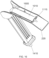
- Each retaining slot 1510 incorporates a hole sized to receive a retaining tab 1605 from cover 1010, as shown in FIG. 16 .
- the retaining tab 1605 from cover 1010 is inserted into the hole of retaining slot 1510.
- Retaining slots 1510 are sized such that the hole is smaller than the associated retaining tab 1605. The hole is raised and smoothed, which holds body tissue away from the hole.
- retaining slot 1510 may include a raised and smoothed portion. Based on this feature, the retaining tab 1605, when inserted into and residing within retaining slot 1510, is recessed within the hole, and does not protrude from the hole of retaining slot 1510. This ensures that no tissue is snagged or caught by the end of retaining tab 1605.
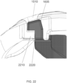
- FIG. 22 illustrates a cutaway of tab 1605 residing within, and not protruding from, retaining slot 1510.
- Tab 1605 deforms around shelf 2210, and tab 1605 snaps into place such that contact between the underside of tab 1605 and the top of shelf 2210 prevents the separation of tab 1605 from shelf 2210.
- Retaining slot 1510 is located on the underside of blade portion 120, and is formed from mold structures that penetrate the blade portion 120 from the underside. The penetration of the mold structures forms holes in the blade portion 120, such as retaining slot 1510, which is shown filled in with tab 1605. To prevent retaining slot 1510 from trapping tissue, it is preferable to minimize the size of retaining slot 1510, as well as limit the number of holes to one hole located on the underside of blade portion 120.
- Retractor 100 is therefore formed using a mold structure that penetrates blade portion 120 only in the location of shelf 2210.
- the formed hole of retaining slot 1510 is minimized in size to be of the same, or approximately the same, size as the width of shelf 2210.
- the manufacturing process includes utilizing the mold structures to form a hole in the underside of the blade portion (e.g., in the hole of retaining slot 1510), opposite shelf 2210.
- a hole in the underside of the blade portion e.g., in the hole of retaining slot 1510, opposite shelf 2210.
- an additional hole 2220 is therefore formed during manufacturing from a mold structure on the top side of blade portion 120, opposite the tissue-facing underside, in order to allow for deformation of retaining tab 1605.
- Hole 2220 is formed to provide for deformation of retaining 1605.
- the location of hole 2220 is optimally located on the top side of blade portion 120, away from tissue contact. Hole 2220 does not proceed through the width of the blade portion 120, thereby minimizing additional hole structures on the patient-facing side of retractor 100.
- retaining slot 1510 is sized to half the width of a conventional hole, due to the use of multiple molds. Therefore, only slot 1510, with a smoothed mound, provides for minimal tissue catch.
- the retractor 100 is formed from an injection mold design. It should be noted that a shrunken hole is smaller than the retaining tab 1605, which is only possible in an injection mold design, and is not feasible with a metal retractor.
- Retractor 100 further includes an on/off switch 1705, located at the bottom of handle 110.
- Switch 1705 may be located adjacent to the connector 1410. Switch 1705 controls one or more of the light source and vacuum source.
- FIG. 18 illustrates the retractor 100 with cover 1010 removed.
- Channel 1105, the cavity, under the smoke evacuation cover 1010 is illustrated extending from a distal end of the barrel portion 215 adjacent to the operative portion 220, past the saddle portion 210, and into a cavity 1810 located in the handle 110.
- Smoke may travel from the intake adjacent to operative portion 220, under the cover 1010, via channel 1105, into the handle cavity 1810.
- the smoke traverses the internal cavity 1810 and exits the handle via connector 1410, which is connected to a smoke evacuation hose and uses suction from the vacuum source.
- FIGS. 18-20 illustrate the electrical connection to the light source 1020, which is normally held in place in channel 1105 by the smoke evacuation cover 1010.
- the wires 1820 lead from the light source 1020 into a power source in the handle 110.
- the power source is controlled by switch 1705.
- the power source may contain sufficient charge for only a single use.
- retractor 100 may include an assembly 1910.
- Assembly 1910 may be made or manufactured separate from the retractor body.
- Assembly 1910 may be include one or more of a power source 1920, wires 1820, switch 1705 and light source 1020.
- assembly 1910 may be inserted, as one pre-formed piece, into the base portion of handle 110.
- Assembly 1910 may be inserted into the cavity of handle 110 from the bottom, and fed up through handle 110, out the top portion of handle 110, adjacent to the saddle portion 210.
- the assembly 1910 may then be placed onto the barrel portion 215, within channel 1105, at which point the light source 1020 and wires 1820 of assembly 1910 are placed into receiving slots 1830.
- the cover 1010 is then placed over the channel 1105, including assembly 1910, and snapped into place.
- a method of utilizing the smoke channel 1105 to remove the smoke from a physician's field of view may include the following. Generating smoke during a surgery or procedure by, for example, use of electro-cauterization tools. This smoke may interfere with the physician's vision, particularly with the field of view.
- the light source 1020 may be focused on the physician's field of view.
- a vacuum source may be switched on, and smoke may be drawn into the retractor via the smoke evacuation channel. The smoke may traverse the smoke evacuation channel, into the handle, and out the bottom of the handle.
- the entire retractor and associated components as disclosed herein, including the blade/handle, handle cover, and cover, are fully compatible with low-cost injection molding, and are able to be manufactured using low cost plastic. Further, the entire retractor assembly is optimal for use as a single-use and disposable product.
- the surgical retractor includes a handle portion joined to a blade portion.
- the blade portion may be perpendicularly joined to the handle portion, such as at a 90 degree angle or approximately 90 degree angle.
- the blade portion may be joined to the handle portion at any suitable angle, such as, for example, a 30 degree angle, 45 degree angle, 110 degree angle or any other suitable angle.
- the blade portion may include a saddle portion, a curved barrel portion, an operative portion, and a channel cover.
- the saddle portion may abut the handle portion, forming a recessed cavity.
- the curved barrel portion may be located distal to the saddle portion and define a channel.
- a light assembly may be disposed within the barrel portion.
- the operative portion may be located distal to, and downwardly angled from, the barrel portion.
- the channel cover may be disposed over the channel within the barrel portion, and may be adapted to hold the light assembly in place.
- the operative portion of the retractor is substantially squared in shape, and includes a plurality of ridges distal to the barrel portion.
- the ridges may be of any suitable dimension.
- the ridges may be dimensioned to grip tissue and hold the tissue away from an operative area.
- the light assembly abuts the operative portion and includes a light source, a switch, a single-use power source, and a housing.
- the channel of the retractor may be a smoke evacuation channel that extends from the barrel portion, through the saddle portion, and into a hollow space in the handle portion.
- the smoke evacuation channel may extend through a length of the handle portion to a connector located at a bottom of the handle portion.
- a vacuum source may be coupled, via a connector, to the bottom of the handle portion. The coupling of the vacuum source provides a fluid connection between the smoke evacuation channel and the vacuum source, which provides suction for removing smoke.
- the surgical retractor includes a handle portion and a blade portion joined to the handle portion.
- the blade portion may include a saddle portion abutting the handle portion and forming a recessed cavity; a curved barrel portion located distal to the saddle portion and defining a channel, the barrel portion including a light assembly disposed within the barrel portion; an operative portion located distal to, and downwardly angled from, the barrel portion; a channel cover disposed over the channel, within the barrel portion, and adapted to hold the light assembly in place, the channel cover including a plurality of retaining tabs; and a plurality of retaining slots located on an underside of the blade portion, the retaining slots sized to minimize a size of the hole of the retaining slot and including a smoothed and raised geometry to facilitate tissue movement without catching.
- Each retaining tab may be sized to fit into one of the plurality of retaining slots, and the retaining slots may be operable to hold the channel cover in place over the channel.
- a self-lighted retractor with the ability to provide bright, shadow-less light to a surgical cavity.
- a dual-purpose smoke evacuation channel and light source holder that couples the light source to the retractor.
- a single-use battery and high volume moldable plastic components that allow for manufacture of a high- quality retractor that is affordable for single use, reducing infection risk.
- an angled retractor blade that is squared, with integral ridges to hold tissue aside during use of the retractor.
- the blade, the handle and the curved section may be integrally molded.
- the material of which the body is formed is a strong, rigid, lightweight plastic (e.g., a polymer).
- a suitable plastic is a glass-fiber reinforced polyarylamide compound that provides high strength and rigidity, surface gloss, and creep resistance.
- An example uses a 50% glass-fiber reinforced polyarylamide compound, but those skilled in the art will understand that other percentages may be used without departing from the scope of the claimed invention.
- Polyarylamides are thermoplastic crystalline polymers of aromatic diamines and aromatic dicarboxylic anhydrides having good heat, fire, and chemical resistance, property retention at high temperatures, dielectric and mechanical properties, and stiffness but low light resistance and processability. Those skilled in the art will understand that other plastics with suitable strength and rigidity also may be used.
- the body is made of a plastic (such as glass-fiber reinforced polyarylamide) having properties of at least one of radiolucence and non- conductivity.
- radiolucence means high transparency to radiation, so that the device may be used when taking, for example, x-ray images.
- Nonconductive as used herein, means essentially dielectric.
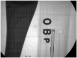
- radiolucence is that the device may be used when taking X-ray images, without obscuring essential structures, as shown in FIG. 23 .
- the "OBP" in FIG. 23 resulted from metal lettering placed below the blades of an embodiment to show the radiolucency.
- the much darker image on the left is of a stainless steel comparison blade, which shows up as black due to its opacity with respect to X-rays.
- Examples described herein may provide light to the tip of the retractor and still remain highly (as much as 99%) radiolucent.
- Prior art devices have, for example, fiber optic cables that obstruct the view when X-ray images are taken, even when the devices are constructed of plastic.
- Metal devices are, of course, not radiolucent at all.
- This radiolucent property means that retractors described herein may not need to be removed prior to the use of imaging techniques in surgical procedures. This can expedite the conduct of a procedure needing anatomic identification and/or device localization.
- An advantage of nonconductivity is that it provides improved safety to patients - in contrast to metal retractors. Currents as low as 0.001 A may be felt by a patient, and larger currents may damage the patient. Embodiments described herein limit currents to less than 10 -6 A, and thus greatly reduce electrical hazards.
- electro-cautery is used extensively in surgical tissue dissection.
- the use of metal retractors exposes the operating surgeon and the patient to the risk of retracted tissue damage due to destructive cautery current being conducted inadvertently.
- Retractors are often used to displace and retract delicate cautery sensitive tissues such small or large bowel (colon), lung, or major blood vessels.
- cautery sensitive tissues such small or large bowel (colon), lung, or major blood vessels.
- retractors are often used to develop surgical tissue pockets in breast and pacemaker surgery.
- Use of a non-electrical conducting material such as is described herein with respect to certain embodiments, prevents any stray electrical energy injury to the retracted tissues. Patient safety is thus enhanced.
- Flexural Strength represents the limit before a material will break under stress. Flexural modulus is the tendency of the material to bend under stress. Both of these parameters are critical to retractor design and resulting performance.
- a retractor blade must be thin enough to not interfere with the medical procedure for which it is used. Very thick blades will tend to fill the hole in the body that the physician needs to work in. An optimal design will have a blade thin enough to allow space for the physician to work.
- metal blades are used because of their high Flexural modulus. They have unlimited flexural strength, because they bend rather than break. Metal blades as thin as 0.5-2 mm are readily available and this thickness is small enough to not interfere with the physician's work space in a wound or operating cavity.
- Stainless steel metal can have a flexural modulus of 180 GPa which will inhibit blade deformation of more than 10 mm under 66,7 N (15 lbs of tip pressure) for most retractor designs.
- Plastic injection molded blades require a thicker blade because they have a lower Flexural Modulus. Blade strength will increase as the cube of the blade thickness, but blade thicknesses larger than 2 mm are not desirable in most physician applications. Typical plastic materials, such as those shown in Table 1 below, have a Flexural Modulus of just a few GPa and a Flexural Strength of less than 200 MPa. These lower value parameters result in retractor blades that deform more than 10mm under use, and are likely to break with less than 133,5 N (30 lbs of force) placed on the tip of an average length retractor blade (50-150 mm long).
- Retractor blades that deform significantly during use increase the physician's difficulty in retracting the tissue during a medical procedure.
- Retractor blades that break with less than 133,5 N (30 lbs of force) can create a hazard to the patient since a broken blade, or pieces of a broken blade, may fall into the patient and create damage.
- Retractor blades made from the plastics listed in the following table will typically bend more than 20 mm under 44,5 N (10 lbs of tip force), and will break at 66,7 N (15 lbs of tip force) (or even less).
- glass fiber is added to the plastic material.
- FIG. 24 shows a variety of plastics with various percentages of glass fiber added.
- glass fiber can increase the Flexural Strength of certain plastics to 300 MPa or above, and increase the Flexural Modulus to 16 GPa or above.
- a certain type of plastic, polyacrylamide is infused with glass fiber to create a flexural strength of over 375 GPa and a Flexural modulus of over 17 GPa.
- Plastics with these properties have the ability to create retractor blades of approximately 2 mm thickness that withstand over 133,5 N (30 lbs of tip force) without breaking and deform less than 10 mm under 66,7 N (15 lbs of force). Additionally, the glass fiber in this material will "glassify” at the surface leaving a very smooth "metal like” finish which is highly desirable in retractor applications.
- the glass fiber in the material also will decrease the likelihood of sharp shards of material being created during an overstress and breakage event. This tendency to create dull edges upon breakage decreases the likelihood that a patient will experience damage if the retractor is overstressed and ultimately broken.
- the breakage characteristics of a material are often measured by Impact Strength. Materials with low impact strength (10-20 J/m) can break under stress into large numbers of sharp shards which can pose a hazard to a patient if material failure occurs during a medical procedure. Sharp shards can cut patient tissue and large numbers of these shards can make it difficult or impossible to remove the broken material from the patient.
- Materials such as glass fiber reinforced polyarylamide used in certain embodiments described herein have a high impact strength (>100 J/m) and will fail with very few fractured component edges (and the resulting edges will be blunt). This breakage characteristic minimizes potential hazard to a patient during product overstress that results in material breakage.
Landscapes
- Health & Medical Sciences (AREA)
- Surgery (AREA)
- Life Sciences & Earth Sciences (AREA)
- Heart & Thoracic Surgery (AREA)
- Engineering & Computer Science (AREA)
- Biomedical Technology (AREA)
- Nuclear Medicine, Radiotherapy & Molecular Imaging (AREA)
- Medical Informatics (AREA)
- Molecular Biology (AREA)
- Animal Behavior & Ethology (AREA)
- General Health & Medical Sciences (AREA)
- Public Health (AREA)
- Veterinary Medicine (AREA)
- Pathology (AREA)
- Oral & Maxillofacial Surgery (AREA)
- Surgical Instruments (AREA)
Description
- Embodiments described herein relate to surgical instrumentation and, more particularly, a retractor according to the preamble of claim 1, forming an unobstructed, illuminated viewing slot for the physician's field of view.
- Light sources that interfere with the physicians field of view, or that do not properly illuminate the field of view, inhibit the physician from seeing critical developments. For example, when performing a dissection, potential blood sources may drain blood into the dissection cavity, and without proper treatment, these blood sources can cause post-surgery infection. Such concerns are pertinent when using breast retractors, which are used for breast augmentation or reconstruction.
- Conventional breast retractors may cause blood to drain into the dissection cavity due to a lack of proper illumination in the field of view.
- Currently, breast retractors require substantial auxiliary lighting. This lighting is expensive, difficult to assemble, requires cleaning and reprocessing after each use, and due to lack of customization for breast retractors, fails to provide sufficient light at desired locations. Namely, practitioners must assemble and secure an independent light source onto the breast retractor prior to the patient procedure. These auxiliary light sources do not provide the physician with the ability to focus the light onto, and illuminate, specific portions of the surgical field without interfering with the physician's field of view.
- Further, auxiliary light sources affixed to a retractor require expensive preparation and components that must be reprocessed after each patient procedure in order to ensure no patient cross-contamination. Without adequate reprocessing, cross contamination from one patient to another can occur. Moreover, even with reprocessing of the light sources, effective reprocessing is not 100% guaranteed, and many hospitals have reported patient cross-contamination due to inadequate or errors in reprocessing.
- A retractor according to the preamble of independent claim 1 is for example known from
US 2008/0108877 A1 andDE 20 2005 019 780 U1 . - A further known retractor is disclosed in
US 2013/0324801 A1 . - Additionally,
US 2012/0078060 A1 andUS 2014/0364695 A1 disclose known specula. - Therefore, as can be seen, there is a need for a retractor according to claim 1.
- The retractor may be made of polymer and according to various embodiments: (1) the polymer is a 50% glass-fiber reinforced polymer; (2) the polymer is a polyarylamide compound; (3) the polymer is a thermoplastic crystalline polymer; (4) the polymer is a thermoplastic crystalline polymer of aromatic diamines and aromatic dicarboxylic anhydrides; (5) the polymer is a glass-fiber reinforced polyarylamide; (6) the polymer is at least 50% glass-fiber reinforced; (7) the polymer has a flexural modulus of at least 17 GPa; (8) the polymer has a flexural strength of at least 375 MPa; (9) the polymer has an impact strength of at least 100 J/m; (10) the illumination assembly is permanently attached to the curved portion; and/or (11) the polymer has a conductivity of less than 10-6 A.
- Further features and advantages will be apparent to those skilled in the art after reviewing the drawings and detailed description provided herein.
-
-
Figure 1 is a side view of a surgical retractor serving as an example; -
Figure 2 is a dimetric view of a surgical retractor serving as an example; -
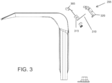
Figure 3 is an exploded view of a surgical retractor serving as an example; -
Figure 4 is a perspective view of a surgical retractor serving as an example; -
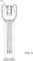
Figure 5 is a rear view of a surgical retractor serving as an example; -
Figure 6 is a perspective view of a surgical retractor serving as an example, with the light assembly removed for clarity; -
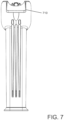
Figure 7 is a front view of a surgical retractor serving as an example; -
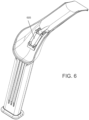
Figure 8 is a top view of a surgical retractor serving as an example; -
Figure 9 is a bottom view of a surgical retractor serving as an example; -
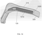
Figure 10 is a top view of an exemplary embodiment; -
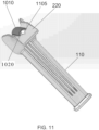
Figure 11 is a front angled view of an exemplary embodiment; -
Figure 12 is a rear view of an exemplary embodiment; -
Figure 13 is a side perspective view of an exemplary embodiment; -
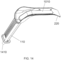
Figure 14 is a top perspective view of an exemplary embodiment; -
Figure 15 is an inverted view of an exemplary embodiment; -
Figure 16 is a side perspective view of an exemplary embodiment; -
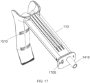
Figure 17 is a rear perspective view of an exemplary embodiment; -
Figure 18 is a top perspective view of an exemplary embodiment; -
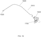
Figure 19 is a side view of an exemplary embodiment; -
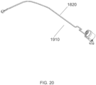
Figure 20 is a side view of an exemplary embodiment; -
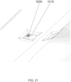
Figure 21 is a view of an exemplary embodiment; -
Figure 22 is another view of an exemplary embodiment; -
Figure 23 is a fluoroscopy image illustrating the radiolucency of an embodiment; -
Figure 24 illustrates flexural strength and flexural modulus for a variety of plastics. - The invention is particularly shown in
figures 10-22 . - The following detailed description is of certain exemplary embodiments. The description is not to be taken in a limiting sense, but is made merely for the purpose of illustrating the general principles of the present retractor.
- Broadly, one or more embodiments provide a surgical retractor including an integrated light source and rounded blade forming an unobstructed, illuminated viewing slot for the physician's field of view. The surgical retractor with integrated light source prevents the problem caused by external light sources- namely, the casting of shadows within the operating cavity. To solve this problem, the integral light source of the surgical retractor is pointed in the same direction as the distal end of the retractor, which causes the light to be directed to the same point where the cutting is being performed.
- The surgical retractor may provide a handle portion generally perpendicularly joined to a blade portion. The blade portion may form an arcuate (curved) shaped barrel portion defining a viewing slot, wherein the blade portion interconnects a saddle portion and an operative portion. The operative portion is dimensioned and adapted for surgery. The saddle portion attaches to the handle portion, while forming a recessed cavity for receiving the light source. The light source and recessed cavity are disposed, dimensioned, and adapted so that the light beam from the light source is directed down the viewing slot.
- Referring now to
Figures 1 through 22 , one or more exemplary embodiments may include asurgical retractor 100 integrated with alight assembly 205. Thesurgical retractor 100 may include ahandle portion 110 generally perpendicularly joined to ablade portion 120. Thehandle portion 110 may be joined to theblade portion 120 atsaddle portion 210. Theblade portion 120 may extend from aproximal end 130 to adistal end 140, wherein theproximal end 130 is joined to thehandle portion 110 atsaddle portion 210. - The
blade portion 120 may be made of any moldable material that is sufficiently resilient including, but not limited to, polystyrene, poly-carbonate, glass filled nylon, or the like, although as explained herein, glass-reinforced polyarylamide is preferred, due its superior strength, radiolucency, and low conductivity. - The
blade portion 120 may form asaddle portion 210, abarrel portion 215, and anoperative portion 220. - The
blade portion 120 may extend from theproximal end 130 to thedistal end 140, wherein thebarrel portion 215 interconnects thesaddle portion 210 and theoperative portion 220. - The
barrel portion 215 may form an arcuate shape along its length so that the trough of the arcuate shape is upwardly oriented, defining a "viewing slot," as illustrated in the drawings. - The
saddle portion 210 may be formed in a bowl-like configuration. Thesaddle portion 210 may form a recessedcavity 605 for receiving thelight assembly 205. A spring or other fastener (not shown) may be provided to secure thelight assembly 205 in the recessedcavity 605. - The
light assembly 205 may include alight source 305, aswitch 310 and apower source 315 connected in series. Thepower source 315 may include batteries, such as button style batteries, adapted to store only sufficient energy for a single use. Alternatively, the batteries may be reusable or rechargeable batteries for multiple uses. Thelight source 305 may be enclosed by ahousing 320. The light source may include a LED, OLED, incandescent, or other suitable light source for emitting a beam of light. Theswitch 310 may be a light tab made from a nonconductive material, such as a Mylar tape, adapted to open circuit the serial electrical circuit of thepower source 315 and thelight source 305, whereby removal of theswitch 310 results in thepower source 315 activating thelight source 305. In certain embodiments, theswitch 310 may utilize any known means of activating/powering thelight source 305, such as, but not limited to, a push button switch, toggle switch, magnetic reed switch or slider switch. - The recessed
cavity 605 and thelight source 305 may be dimensioned and adapted so that the beam of light is directed along the viewing slot, toward thedistal end 140 of theblade portion 120, as illustrated inFIGS. 2 and6 , which illustrate thelight source 305 disposed in thesaddle portion 210 and directed down the viewing slot ofbarrel portion 215. As shown, thehousing 320 is disposed below the viewing slot, and therefore out of the field of view of the end user. - The
operative portion 220 may be downwardly angled away from the viewing slot so as to not obstruct the above-mentioned field of view. Theoperative portion 220 may be substantially flat and/or substantially square or rectangular in shape, providing a distal tip with a plurality ofridges 710 opposite thebarrel portion 215. The shape of the distal tip and theridges 710 may be dimensioned and adapted to hold the tissue of the breast recessed cavity away from the area of dissection, which helps the end user in the dissection procedure.Ridges 710 may be of any suitable depth and size in order to hold the breast tissue. - A method of using the retractor, not forming part of the invention, may include the following. The
surgical retractor 100 disclosed above may be provided. A user may remove thesurgical retractor 100 from a sterile package just prior to the surgical procedure. The user may remove theswitch 310 to energize thelight source 305. The user may then create an incision in the patient and use thesurgical retractor 100 to create a pocket through this incision. The pocket will be used for breast augmentation, reconstruction, or other breast related surgical procedures. When the procedure is over, theretractor 100 may be discarded, because thelight source 305 may be designed to not be replaceable and the power source may only be sufficient to power the light source for a single procedure, thereby allowing disposal of the present embodiment after one use. - In certain embodiments, the
surgical retractor 100 can be adapted to form a retractor suitable for other procedures such as a nasal retractor spine retractor, orthopedic retractor, and retractors for other surgical procedures. All such retractors maintain the present embodiment of fully assembled, lighted, and single use. - In certain embodiments, the retractor may be used in a medical procedure performed by robots. Such robots will also need lighted retractors to allow visualization of the surgical cavity. Robotic procedures also benefit from enhanced field of view, and from single use components that eliminate the risk of patient cross contamination. An embodiment will contain suitable connecting features for attachment to a medical robot.
-
FIGS. 10-22 depict the invention comprising aretractor 100 with alight source 1020 located toward or near thedistal end 140 of thebarrel portion 215. It should be noted that some or all of the features as discussed herein with reference to these embodiment may be used in conjunction with, or in place of, some or all of the features in embodiments previously disclosed. - Referring now to
FIGS. 10-20 ,retractor 100 includes alight source 1020 located nearer to theoperative portion 220. Thelight source 1020 may be located toward the distal end ofbarrel portion 215.Light source 1020 may be located at any point near thedistal end 140, including within thebarrel portion 215 and theoperative portion 220. -
Light source 1020 may include a wide dispersion angle, such as a 100 degree angle, or any suitable variation thereof. The wide dispersion angle may be attained by using a wide dispersion LED. The use oflight source 1020, with a wide dispersion angle, and its location toward thedistal end 140 of the blade portion, provides light to the entire operative area located in front ofoperative portion 220. - As illustrated in
FIG. 10 , thelight source 1020 may be associated with some or all of the features oflight assembly 205, includinglight source 305, aswitch 310 and apower source 315. - Further, in this embodiment,
operative portion 220 may includeintegral ridges 710, shown inFIG. 13 , which provide for holding back tissue during use of theretractor 100. - A
smoke evacuation channel 1105, withchannel cover 1010, is located withinbarrel portion 215, and may extend, at one end, up tooperative portion 220. In some embodiments, thesmoke evacuation channel 1105 andcover 1010 may extend into a portion of theoperative portion 220 at one end. Thechannel 1105 may be a hollow cavity defining thebarrel portion 215. - At a second end, the smoke
evacuation channel cover 1010 may be anchored in thesaddle portion 210. Thesmoke evacuation channel 1105 may then extend into a hollow space located withinhandle 110. Thus, handle 110 may include a hollow space for receiving thesmoke evacuation channel 1105 andcover 1010. - As illustrated, the smoke
evacuation channel cover 1010 may be angled at certain points. Thesmoke evacuation channel 1105 also incorporateslight source 1020, according to the invention. -
Light source 1020 may further include alight holder 1115. -
Channel 1105, coupled withcover 1010, provided for air and smoke to enterchannel 1105 via a gap betweencover 1010 and thebarrel portion 215, thereby guiding smoke away from the physician's field of view. The gap may be provided on either side of thelight source 1020. - The
smoke channel 1105 andcover 1010 may extend from thedistal end 140 of theretractor 100, near theoperative portion 220, towardshandle 110, as shown inFIG. 14 . -
Channel 1105 conducts air or smoke received at the entrance of thechannel 1105, located at the distal end of theblade portion 120, towards thehandle portion 110.Channel 1105 therefore acts as an air conduit and moves air/smoke away from the incision site and/or the physician's field of view. - A vacuum source may be attached to the
retractor 100. The vacuum source may be connected to any point of thehandle portion 110, including the bottom of thehandle 110, distal to the saddle portion. Alternatively, the vacuum source may be attached at any suitable location to thehandle portion 110, or may be attached directly to thecover 1010 at the location of thesaddle portion 210. - The
handle portion 110 may be hollow and act as an air conduit. Smoke or air may leave thechannel 1105 at the entrance to thehandle portion 110, which may include a hollow chamber that is in communication withchannel 1105. Thehandle portion 110 may include a portion ofchannel 1105, which is integral with the other portion ofcover 1010. Alternatively, thehandle portion 110 may include a second cover in communication withchannel 1105, and may receive the smoke/air fromchannel 1105. The vacuum source may be attached at the base of thehandle portion 110. - The vacuum source is operable to provide suction, via the
channel 1105, in order to move air/smoke away from an incision site or the physician's field of view. The air/smoke enters thechannel 1105 at an opening created by the gap betweencover 1010 andbarrel portion 215, located near the blade tip, traverses thechannel 1105 toward thesaddle portion 210, and enters thehandle portion 110. The vacuum source pulls the air/smoke from the handle. - As illustrated in the inverted view of the
retractor 100 inFIG. 15 , thechannel 1105 andcover 1010 descend to thebottom 1520 of thehandle portion 110. Thecover 1010 includes aconnector 1410 at the bottom 1520, which fluidly connects thechannel 1105 to the vacuum source and draws the smoke/air out of the channel. - As illustrated in
FIGS. 11-13 , thesmoke channel 1105 advantageously abutsoperative portion 220 in order to provide smoke evacuation from the operative site. - Further, the
light source 1020 may be provided at an angle similar to, or substantially the same as, the downward angle of theoperative portion 220 relative to thebarrel portion 215, in order to focus the light from thelight source 1020 onto the area retracted by theoperative portion 220. - The
light source 1020 may alternatively be provided at an angle substantially similar to thebarrel portion 215, and may not slope downward with theoperative portion 220. This may still cause the light source to illuminate the operative area, due to the wide dispersion angle of thelight source 1020. - Yet further illustrated is the angle of the
operative portion 220, particularly at the distal end as it slopes downward.Integral ridges 710 provide, along with the angle of theblade 120 at itsoperative portion 220 and the square shape of theoperative portion 220, for optimal methods and apparatus for holding back tissue during use. -
Blade 120 may incorporate one ormore retaining slots 1510, shown inFIGS. 15 and17 , on the underside of the blade. Theslots 1510 are operable to holdcover 1010 in place. The retainingslots 1510 are also optimally designed to not catch tissue during a surgical procedure, such as when theblade 120 is inserted into the body cavity. - Each retaining
slot 1510 incorporates a hole sized to receive aretaining tab 1605 fromcover 1010, as shown inFIG. 16 . To holdcover 1010 in place on top ofblade 120, theretaining tab 1605 fromcover 1010 is inserted into the hole of retainingslot 1510. Retainingslots 1510 are sized such that the hole is smaller than the associatedretaining tab 1605. The hole is raised and smoothed, which holds body tissue away from the hole. - As illustrated in
FIG. 21 , retainingslot 1510 may include a raised and smoothed portion. Based on this feature, theretaining tab 1605, when inserted into and residing within retainingslot 1510, is recessed within the hole, and does not protrude from the hole of retainingslot 1510. This ensures that no tissue is snagged or caught by the end of retainingtab 1605. -
FIG. 22 illustrates a cutaway oftab 1605 residing within, and not protruding from, retainingslot 1510.Tab 1605 deforms aroundshelf 2210, andtab 1605 snaps into place such that contact between the underside oftab 1605 and the top ofshelf 2210 prevents the separation oftab 1605 fromshelf 2210. -
Shelf 2210 is located opposite retainingslot 1510. Retainingslot 1510 is located on the underside ofblade portion 120, and is formed from mold structures that penetrate theblade portion 120 from the underside. The penetration of the mold structures forms holes in theblade portion 120, such as retainingslot 1510, which is shown filled in withtab 1605. To prevent retainingslot 1510 from trapping tissue, it is preferable to minimize the size of retainingslot 1510, as well as limit the number of holes to one hole located on the underside ofblade portion 120. -
Retractor 100 is therefore formed using a mold structure that penetratesblade portion 120 only in the location ofshelf 2210. The formed hole of retainingslot 1510 is minimized in size to be of the same, or approximately the same, size as the width ofshelf 2210. - In an embodiment, the manufacturing process includes utilizing the mold structures to form a hole in the underside of the blade portion (e.g., in the hole of retaining slot 1510),
opposite shelf 2210. By penetrating theblade portion 120 only in the location of the shelf, and in no other location on the underside of the blade portion, the hole on the underside, which may face the patient during a procedure, is only as wide as the shelf. Thus, the hole size is reducing trapping of patient tissue. - Yet, by reducing the hole area for retaining
slot 1510, and providing for one hole the same width ofshelf 2210, during manufacturing, retainingtab 1605 cannot deform into place to fit aroundshelf 2210. - As illustrated in
FIG. 22 , anadditional hole 2220 is therefore formed during manufacturing from a mold structure on the top side ofblade portion 120, opposite the tissue-facing underside, in order to allow for deformation of retainingtab 1605. -
Hole 2220 is formed to provide for deformation of retaining 1605. The location ofhole 2220 is optimally located on the top side ofblade portion 120, away from tissue contact.Hole 2220 does not proceed through the width of theblade portion 120, thereby minimizing additional hole structures on the patient-facing side ofretractor 100. - As illustrated in
FIGS. 21-22 , retainingslot 1510, is sized to half the width of a conventional hole, due to the use of multiple molds. Therefore, onlyslot 1510, with a smoothed mound, provides for minimal tissue catch. - In an embodiment, the
retractor 100 is formed from an injection mold design. It should be noted that a shrunken hole is smaller than theretaining tab 1605, which is only possible in an injection mold design, and is not feasible with a metal retractor. -
Retractor 100 further includes an on/offswitch 1705, located at the bottom ofhandle 110.Switch 1705 may be located adjacent to theconnector 1410.Switch 1705 controls one or more of the light source and vacuum source. -
FIG. 18 illustrates theretractor 100 withcover 1010 removed.Channel 1105, the cavity, under thesmoke evacuation cover 1010, is illustrated extending from a distal end of thebarrel portion 215 adjacent to theoperative portion 220, past thesaddle portion 210, and into acavity 1810 located in thehandle 110. Smoke may travel from the intake adjacent tooperative portion 220, under thecover 1010, viachannel 1105, into thehandle cavity 1810. The smoke traverses theinternal cavity 1810 and exits the handle viaconnector 1410, which is connected to a smoke evacuation hose and uses suction from the vacuum source. -
FIGS. 18-20 illustrate the electrical connection to thelight source 1020, which is normally held in place inchannel 1105 by thesmoke evacuation cover 1010. Thewires 1820 lead from thelight source 1020 into a power source in thehandle 110. The power source is controlled byswitch 1705. The power source may contain sufficient charge for only a single use. - As illustrated in
FIG. 19 ,retractor 100 may include anassembly 1910.Assembly 1910 may be made or manufactured separate from the retractor body.Assembly 1910 may be include one or more of apower source 1920,wires 1820,switch 1705 andlight source 1020. - In an exemplary method of manufacture,
assembly 1910 may be inserted, as one pre-formed piece, into the base portion ofhandle 110.Assembly 1910 may be inserted into the cavity ofhandle 110 from the bottom, and fed up throughhandle 110, out the top portion ofhandle 110, adjacent to thesaddle portion 210. Theassembly 1910 may then be placed onto thebarrel portion 215, withinchannel 1105, at which point thelight source 1020 andwires 1820 ofassembly 1910 are placed into receivingslots 1830. Thecover 1010 is then placed over thechannel 1105, includingassembly 1910, and snapped into place. - A method of utilizing the
smoke channel 1105 to remove the smoke from a physician's field of view, which is not part of the invention, may include the following. Generating smoke during a surgery or procedure by, for example, use of electro-cauterization tools. This smoke may interfere with the physician's vision, particularly with the field of view. Thelight source 1020 may be focused on the physician's field of view. During the course of the procedure, a vacuum source may be switched on, and smoke may be drawn into the retractor via the smoke evacuation channel. The smoke may traverse the smoke evacuation channel, into the handle, and out the bottom of the handle. - It should be noted that the entire retractor and associated components as disclosed herein, including the blade/handle, handle cover, and cover, are fully compatible with low-cost injection molding, and are able to be manufactured using low cost plastic. Further, the entire retractor assembly is optimal for use as a single-use and disposable product.
- It should be understood that, among the advantages of the retractor, the need for a separate smoke evacuation tool is eliminated. Additionally, a bright light source is provided to illuminate the surgical cavity.
- The surgical retractor includes a handle portion joined to a blade portion. The blade portion may be perpendicularly joined to the handle portion, such as at a 90 degree angle or approximately 90 degree angle. Alternatively, the blade portion may be joined to the handle portion at any suitable angle, such as, for example, a 30 degree angle, 45 degree angle, 110 degree angle or any other suitable angle.
- Also, the blade portion may include a saddle portion, a curved barrel portion, an operative portion, and a channel cover. The saddle portion may abut the handle portion, forming a recessed cavity. The curved barrel portion may be located distal to the saddle portion and define a channel. Within the barrel portion, a light assembly may be disposed. The operative portion may be located distal to, and downwardly angled from, the barrel portion. The channel cover may be disposed over the channel within the barrel portion, and may be adapted to hold the light assembly in place.
- In a variant, the operative portion of the retractor is substantially squared in shape, and includes a plurality of ridges distal to the barrel portion. The ridges may be of any suitable dimension. The ridges may be dimensioned to grip tissue and hold the tissue away from an operative area.
- According to an alternative, the light assembly abuts the operative portion and includes a light source, a switch, a single-use power source, and a housing.
- The channel of the retractor may be a smoke evacuation channel that extends from the barrel portion, through the saddle portion, and into a hollow space in the handle portion.
- The smoke evacuation channel may extend through a length of the handle portion to a connector located at a bottom of the handle portion. A vacuum source may be coupled, via a connector, to the bottom of the handle portion. The coupling of the vacuum source provides a fluid connection between the smoke evacuation channel and the vacuum source, which provides suction for removing smoke.
- The surgical retractor includes a handle portion and a blade portion joined to the handle portion. The blade portion may include a saddle portion abutting the handle portion and forming a recessed cavity; a curved barrel portion located distal to the saddle portion and defining a channel, the barrel portion including a light assembly disposed within the barrel portion; an operative portion located distal to, and downwardly angled from, the barrel portion; a channel cover disposed over the channel, within the barrel portion, and adapted to hold the light assembly in place, the channel cover including a plurality of retaining tabs; and a plurality of retaining slots located on an underside of the blade portion, the retaining slots sized to minimize a size of the hole of the retaining slot and including a smoothed and raised geometry to facilitate tissue movement without catching. Each retaining tab may be sized to fit into one of the plurality of retaining slots, and the retaining slots may be operable to hold the channel cover in place over the channel.
- Therefore, provided is a self-lighted retractor with the ability to provide bright, shadow-less light to a surgical cavity. In accordance with the invention, also provided is a dual-purpose smoke evacuation channel and light source holder that couples the light source to the retractor. Further may be provided a single-use battery and high volume moldable plastic components that allow for manufacture of a high- quality retractor that is affordable for single use, reducing infection risk. Yet further may be provided an angled retractor blade that is squared, with integral ridges to hold tissue aside during use of the retractor.
- The blade, the handle and the curved section (referred to herein collectively as "the body") may be integrally molded. In at least one exemplary embodiment, the material of which the body is formed is a strong, rigid, lightweight plastic (e.g., a polymer). One example of a suitable plastic is a glass-fiber reinforced polyarylamide compound that provides high strength and rigidity, surface gloss, and creep resistance. An example uses a 50% glass-fiber reinforced polyarylamide compound, but those skilled in the art will understand that other percentages may be used without departing from the scope of the claimed invention.
- Polyarylamides are thermoplastic crystalline polymers of aromatic diamines and aromatic dicarboxylic anhydrides having good heat, fire, and chemical resistance, property retention at high temperatures, dielectric and mechanical properties, and stiffness but low light resistance and processability. Those skilled in the art will understand that other plastics with suitable strength and rigidity also may be used.
- In one or more examples, the body is made of a plastic (such as glass-fiber reinforced polyarylamide) having properties of at least one of radiolucence and non- conductivity. As used herein, "radiolucence" means high transparency to radiation, so that the device may be used when taking, for example, x-ray images. "Nonconductive," as used herein, means essentially dielectric.
- An advantage of radiolucence is that the device may be used when taking X-ray images, without obscuring essential structures, as shown in
FIG. 23 . The "OBP" inFIG. 23 resulted from metal lettering placed below the blades of an embodiment to show the radiolucency. The much darker image on the left is of a stainless steel comparison blade, which shows up as black due to its opacity with respect to X-rays. - Examples described herein may provide light to the tip of the retractor and still remain highly (as much as 99%) radiolucent. Prior art devices have, for example, fiber optic cables that obstruct the view when X-ray images are taken, even when the devices are constructed of plastic. Metal devices are, of course, not radiolucent at all.
- This radiolucent property means that retractors described herein may not need to be removed prior to the use of imaging techniques in surgical procedures. This can expedite the conduct of a procedure needing anatomic identification and/or device localization.
- An advantage of nonconductivity is that it provides improved safety to patients - in contrast to metal retractors. Currents as low as 0.001 A may be felt by a patient, and larger currents may damage the patient. Embodiments described herein limit currents to less than 10-6 A, and thus greatly reduce electrical hazards.
- For example, electro-cautery is used extensively in surgical tissue dissection. The use of metal retractors exposes the operating surgeon and the patient to the risk of retracted tissue damage due to destructive cautery current being conducted inadvertently. Retractors are often used to displace and retract delicate cautery sensitive tissues such small or large bowel (colon), lung, or major blood vessels. Cautery injury to these tissues can create major complications. In addition, retractors are often used to develop surgical tissue pockets in breast and pacemaker surgery. Use of a non-electrical conducting material, such as is described herein with respect to certain embodiments, prevents any stray electrical energy injury to the retracted tissues. Patient safety is thus enhanced.
- As those skilled in the art will understand, strength is a function of both the material and the design. Designs using weaker material than is described herein need to be thicker and more rounded. Both of these traits will decrease the favorability of a retractor, which should not block visibility of the body cavity.
- Flexural Strength represents the limit before a material will break under stress. Flexural modulus is the tendency of the material to bend under stress. Both of these parameters are critical to retractor design and resulting performance. First, a retractor blade must be thin enough to not interfere with the medical procedure for which it is used. Very thick blades will tend to fill the hole in the body that the physician needs to work in. An optimal design will have a blade thin enough to allow space for the physician to work. Typically metal blades are used because of their high Flexural modulus. They have unlimited flexural strength, because they bend rather than break. Metal blades as thin as 0.5-2 mm are readily available and this thickness is small enough to not interfere with the physician's work space in a wound or operating cavity. Stainless steel metal can have a flexural modulus of 180 GPa which will inhibit blade deformation of more than 10 mm under 66,7 N (15 lbs of tip pressure) for most retractor designs.
- Plastic injection molded blades require a thicker blade because they have a lower Flexural Modulus. Blade strength will increase as the cube of the blade thickness, but blade thicknesses larger than 2 mm are not desirable in most physician applications. Typical plastic materials, such as those shown in Table 1 below, have a Flexural Modulus of just a few GPa and a Flexural Strength of less than 200 MPa. These lower value parameters result in retractor blades that deform more than 10mm under use, and are likely to break with less than 133,5 N (30 lbs of force) placed on the tip of an average length retractor blade (50-150 mm long).
- Retractor blades that deform significantly during use increase the physician's difficulty in retracting the tissue during a medical procedure. Retractor blades that break with less than 133,5 N (30 lbs of force) can create a hazard to the patient since a broken blade, or pieces of a broken blade, may fall into the patient and create damage. Retractor blades made from the plastics listed in the following table will typically bend more than 20 mm under 44,5 N (10 lbs of tip force), and will break at 66,7 N (15 lbs of tip force) (or even less).
-
POLYMER TYPE FLEXURAL STRENGTH (MPa) FLEXURAL STRENGTH (MPa) Polyamide-Imide 175 5 Polycarbonate 90 2.3 Polyethylene, MDPE 40 0.7 Polyethylene Terephthalate (PET) 80 1 - To increase the flexural modulus and flexural strength of plastic, in an embodiment, glass fiber is added to the plastic material.
FIG. 24 shows a variety of plastics with various percentages of glass fiber added. - It can be seen from the above that the addition of glass fiber can increase the Flexural Strength of certain plastics to 300 MPa or above, and increase the Flexural Modulus to 16 GPa or above. In an exemplary embodiment, a certain type of plastic, polyacrylamide, is infused with glass fiber to create a flexural strength of over 375 GPa and a Flexural modulus of over 17 GPa.
- Plastics with these properties have the ability to create retractor blades of approximately 2 mm thickness that withstand over 133,5 N (30 lbs of tip force) without breaking and deform less than 10 mm under 66,7 N (15 lbs of force). Additionally, the glass fiber in this material will "glassify" at the surface leaving a very smooth "metal like" finish which is highly desirable in retractor applications.
- The glass fiber in the material also will decrease the likelihood of sharp shards of material being created during an overstress and breakage event. This tendency to create dull edges upon breakage decreases the likelihood that a patient will experience damage if the retractor is overstressed and ultimately broken.
- Additionally, the way in which a material breaks can be important in medical applications. The breakage characteristics of a material are often measured by Impact Strength. Materials with low impact strength (10-20 J/m) can break under stress into large numbers of sharp shards which can pose a hazard to a patient if material failure occurs during a medical procedure. Sharp shards can cut patient tissue and large numbers of these shards can make it difficult or impossible to remove the broken material from the patient.
- Materials (such as glass fiber reinforced polyarylamide) used in certain embodiments described herein have a high impact strength (>100 J/m) and will fail with very few fractured component edges (and the resulting edges will be blunt). This breakage characteristic minimizes potential hazard to a patient during product overstress that results in material breakage.
Claims (8)
- A surgical retractor (100), comprising:a blade portion (120) having a top surface and a bottom surface, and having a proximal end and a distal end, said blade portion (120) comprising a smoke evacuation channel (1105);a handle portion (110) connected to said proximal end of said blade portion (120); andan illumination assembly comprising at least one light source (1020), at least one battery and a switch (1705) for energizing the light source (1020), with the illumination assembly being attached to the retractor (100),characterized in that the smoke evacuation channel (1105) incorporates the light source (1020) within the smoke evacuation channel (1105).
- The surgical retractor (100) according to claim 1, wherein said illumination assembly is permanently attached to the retractor (100).
- The surgical retractor (100) according to any of the preceding claims, wherein the switch (1705) permits only a single activation by a user.
- The surgical retractor (100) according to any of the preceding claims, wherein the switch (1705) comprises a nonconductive tab.
- The surgical retractor (100) according to any of the preceding claims, further comprising a cover (1010) for said smoke evacuation channel (1105).
- The surgical retractor (100) as in claim 5, further comprising retaining slots (1510) that attach said cover (1010) to said blade portion (120), and wherein said cover (1010) comprises tabs (1605) corresponding to said retaining slots (1510).
- The surgical retractor (100) as in any of the preceding claims, wherein said smoke evacuation channel (1105) extends at least from said distal end of said blade portion (120) to said handle portion (110).
- The surgical retractor (100) according to claim 5 or 6, further comprising a barrel portion, wherein the cover (1010) is disposed over the channel (1105) within the barrel portion and adapted to hold the light assembly in place.
Applications Claiming Priority (3)
| Application Number | Priority Date | Filing Date | Title |
|---|---|---|---|
| US201562170280P | 2015-06-03 | 2015-06-03 | |
| US201562258806P | 2015-11-23 | 2015-11-23 | |
| PCT/US2016/035508 WO2016196788A1 (en) | 2015-06-03 | 2016-06-02 | Retractor |
Publications (3)
| Publication Number | Publication Date |
|---|---|
| EP3302292A1 EP3302292A1 (en) | 2018-04-11 |
| EP3302292A4 EP3302292A4 (en) | 2019-05-22 |
| EP3302292B1 true EP3302292B1 (en) | 2023-10-18 |
Family
ID=57442223
Family Applications (1)
| Application Number | Title | Priority Date | Filing Date |
|---|---|---|---|
| EP16804432.9A Active EP3302292B1 (en) | 2015-06-03 | 2016-06-02 | Retractor |
Country Status (6)
| Country | Link |
|---|---|
| US (1) | US10952712B2 (en) |
| EP (1) | EP3302292B1 (en) |
| CN (1) | CN108348229A (en) |
| DK (1) | DK3302292T3 (en) |
| ES (1) | ES2968069T3 (en) |
| WO (1) | WO2016196788A1 (en) |
Families Citing this family (17)
| Publication number | Priority date | Publication date | Assignee | Title |
|---|---|---|---|---|
| US9913577B2 (en) | 2010-09-28 | 2018-03-13 | Obp Medical Corporation | Speculum |
| US9867602B2 (en) | 2015-02-05 | 2018-01-16 | Obp Medical Corporation | Illuminated surgical retractor |
| US10420538B2 (en) | 2015-02-05 | 2019-09-24 | Obp Medical Corporation | Illuminated surgical retractor |
| US10881387B2 (en) | 2015-06-03 | 2021-01-05 | Obp Medical Corporation | Retractor |
| US10939899B2 (en) | 2015-06-03 | 2021-03-09 | Obp Medical Corporation | End cap assembly for retractor and other medical devices |
| US10349823B2 (en) | 2016-03-11 | 2019-07-16 | Colorado Voice Clinic, P.C. | Retractor and tip extender therefor |
| CN109310410A (en) * | 2016-06-10 | 2019-02-05 | Obp医学公司 | Illuminated operation retractor |
| US10722621B2 (en) | 2016-07-11 | 2020-07-28 | Obp Medical Corporation | Illuminated suction device |
| USD866759S1 (en) | 2017-03-13 | 2019-11-12 | Colorado Voice Clinic, P.C. | Retractor |
| US10687793B2 (en) | 2017-07-18 | 2020-06-23 | Obp Medical Corporation | Minimally invasive no touch (MINT) procedure for harvesting the great saphenous vein (GSV) and venous hydrodissector and retractor for use during the MINT procedure |
| US10278572B1 (en) | 2017-10-19 | 2019-05-07 | Obp Medical Corporation | Speculum |
| US10799229B2 (en) | 2018-02-20 | 2020-10-13 | Obp Medical Corporation | Illuminated medical devices |
| WO2019164795A1 (en) | 2018-02-20 | 2019-08-29 | Obp Medical Corporation | Illuminated medical devices |
| USD911521S1 (en) | 2019-02-19 | 2021-02-23 | Obp Medical Corporation | Handle for medical devices including surgical retractors |
| USD904607S1 (en) * | 2019-05-07 | 2020-12-08 | Obp Medical Corporation | Nasal retractor |
| US10959609B1 (en) | 2020-01-31 | 2021-03-30 | Obp Medical Corporation | Illuminated suction device |
| US10966702B1 (en) | 2020-02-25 | 2021-04-06 | Obp Medical Corporation | Illuminated dual-blade retractor |
Family Cites Families (383)
| Publication number | Priority date | Publication date | Assignee | Title |
|---|---|---|---|---|
| US1326300A (en) | 1919-12-30 | Iighi ibanshiiting subglcal device | ||
| US559122A (en) | 1896-04-28 | Endoscopic instrument | ||
| US659182A (en) | 1900-05-21 | 1900-10-02 | George P Pilling | Retractor. |
| US2247258A (en) | 1938-12-12 | 1941-06-24 | Kulite Corp | Surgical instrument |
| US2235979A (en) | 1940-06-03 | 1941-03-25 | Albert L Brown | Surgical and diagnostic instrument |
| US2482971A (en) | 1947-07-11 | 1949-09-27 | Golson Kelly Kendall | Self-illuminated transparent proctoscope |
| US2592190A (en) | 1948-08-27 | 1952-04-08 | Nat Electric Instr Company Inc | Illuminated speculum |
| US3332414A (en) | 1964-01-20 | 1967-07-25 | Monarch Molding Inc | Vaginal speculum having selectively locked angular and vertical blade adjustment means |
| US3324850A (en) | 1964-04-08 | 1967-06-13 | Aubern Instr Corp | Illuminated vaginal speculum with rotatable cam pivoting and locking means |
| US3532088A (en) | 1966-02-23 | 1970-10-06 | Bio Analytical Labor Inc | Speculum instrument |
| GB1171193A (en) | 1967-06-13 | 1969-11-19 | William Noel Vellacott | Improvements in or relating to Medical Instruments |
| US3638644A (en) * | 1969-03-05 | 1972-02-01 | Michael Elbert | Illuminated surgical speculum |
| US3675641A (en) | 1969-11-21 | 1972-07-11 | Bio Analytical Labor Inc | Speculum instrument and isolated light means therefor |
| US3592199A (en) * | 1970-02-09 | 1971-07-13 | Medical Products Corp | Autoclavable surgical instrument illumination |
| US3716047A (en) | 1970-12-21 | 1973-02-13 | Welch Allyn Inc | Disposable light-conductive speculum |
| US3815585A (en) | 1971-01-14 | 1974-06-11 | Bio Analytical Labor Inc | Disposable vaginal speculum |
| US3729006A (en) | 1971-05-27 | 1973-04-24 | M Kanbar | Disposable surgical retractors |
| DE2128855A1 (en) | 1971-06-11 | 1972-12-28 | Manning, Claus Reinhard, 4006 Erkrath-Unterbach | Speculum for instrumental diagnosis of the vagina |
| BE789022A (en) * | 1971-09-21 | 1973-03-20 | Gobels Georg | DIRECT VISION LARYNGOSCOPE |
| US3762400A (en) | 1971-10-26 | 1973-10-02 | Donald B Mc | Medical examining instrument |
| US3851642A (en) | 1971-10-26 | 1974-12-03 | Medical Testing Syst Inc | Medical examining instrument |
| US3769968A (en) | 1971-11-22 | 1973-11-06 | L Blount | Speculum |
| US3789835A (en) | 1972-03-16 | 1974-02-05 | R Whitman | Illuminating attachments for vaginal speculum |
| IT985204B (en) | 1972-05-26 | 1974-11-30 | Adelman Stuart Lee | IMPROVEMENT IN ENDOSCOPES AND THE LIKE |
| US3934578A (en) | 1974-05-28 | 1976-01-27 | Propper Manufacturing Co., Inc. | Direct illumination otoscope |
| US3978850A (en) | 1975-03-24 | 1976-09-07 | Welch Allyn, Inc. | Medical diagnostic instruments |
| US4210133A (en) | 1975-10-21 | 1980-07-01 | Consejo Nacional De Ciencia Y Tecnologia | Vaginal microscope |
| US4067323A (en) | 1975-12-02 | 1978-01-10 | Concept Inc. | Light for vaginal speculum |
| US4156424A (en) | 1978-05-01 | 1979-05-29 | Burgin Kermit H | Locking adjustable speculum |
| US4226228A (en) | 1978-11-02 | 1980-10-07 | Shin Hee J | Multiple joint retractor with light |
| US4300541A (en) | 1979-02-09 | 1981-11-17 | Kermit Burgin | Speculum lens structure |
| US4527553A (en) * | 1980-04-28 | 1985-07-09 | Upsher Michael S | Laryngoscope with improved light source |
| US4638792A (en) | 1979-12-20 | 1987-01-27 | Burgin Kermit H | Adjustable speculum with incorporated lighting system |
| US4502468A (en) | 1979-12-20 | 1985-03-05 | Burgin Kermit H | Adjustable speculum with incorporated lighting system |
| US4337763A (en) * | 1980-04-21 | 1982-07-06 | The United States Of America As Represented By The Department Of Health, Education And Welfare | Illuminated surgical instrument |
| IE49491B1 (en) | 1980-06-26 | 1985-10-16 | Inst For Ind Res & Standards | A vaginal speculum |
| FR2490478A1 (en) | 1980-09-24 | 1982-03-26 | Chouraqui Albert | Speculum with built-in illumination - has light source mounted on inside surface of blade powered by battery lamp or laser |
| US4934352A (en) | 1982-10-22 | 1990-06-19 | Sullivan Jr Eugene M | Surgical retractor handle construction |
| US4492220A (en) | 1982-11-15 | 1985-01-08 | Hayes Allen L | Vaginal speculum protector |
| US4546761A (en) | 1983-01-12 | 1985-10-15 | Mccullough Cartwright Pharmaceutical Corp. | Large animal speculum holder and battery-powered illuminator |
| US5179938A (en) * | 1983-02-17 | 1993-01-19 | The Trylon Corporation | Apparatus for endoscopic examination of body cavity using chemiluminescent light source |
| US4551129A (en) | 1983-04-08 | 1985-11-05 | Coleman D Jackson | Technique and apparatus for intraocular and microsurgery including lighter-irrigator hypodermic tube |
| US4657012A (en) | 1983-11-16 | 1987-04-14 | Burgin Kermit H | Surgical instrument with incorporated lighting system |
| US4562832A (en) | 1984-01-21 | 1986-01-07 | Wilder Joseph R | Medical instrument and light pipe illumination assembly |
| US4566439A (en) | 1984-07-16 | 1986-01-28 | Burgin Kermit H | Acrylooptic examination device with auxiliary light |
| CA1216202A (en) | 1984-08-22 | 1987-01-06 | David J. Walsh | Light attachment for speculum |
| US4574784A (en) * | 1984-09-04 | 1986-03-11 | Soloway David J | Laryngoscope |
| US4607623A (en) | 1984-11-08 | 1986-08-26 | Jack Bauman | Unitary insert support frame for the handle of an examining device |
| IN164361B (en) | 1985-01-23 | 1989-03-04 | Trylon Ass Ltd | |
| US4597383A (en) | 1985-04-25 | 1986-07-01 | Luxtec Corporation | Fiber-optic illuminated vaginal speculum |
| US5054906A (en) | 1986-01-17 | 1991-10-08 | Brimfield Precision, Inc. | Indirectly illuminating ophthalmological speculum |
| US4766887A (en) | 1986-06-19 | 1988-08-30 | Welch Allyn, Inc. | Disposable vaginal speculum |
| US4807600A (en) | 1986-10-15 | 1989-02-28 | Hayes Allen L | Speculum protector |
| US5063908A (en) | 1989-06-02 | 1991-11-12 | Collins Jason H | Adapter for cervical speculum |
| US4884559A (en) | 1987-12-04 | 1989-12-05 | Collins Jason H | Surgical speculum |
| US4971036A (en) | 1987-12-04 | 1990-11-20 | Collins Jason H | Vaginal speculum |
| US5179937A (en) | 1988-02-04 | 1993-01-19 | Lee Chenault D | Disposable vaginal speculum |
| US4905670A (en) | 1988-12-28 | 1990-03-06 | Adair Edwin Lloyd | Apparatus for cervical videoscopy |
| US5143054A (en) | 1988-12-28 | 1992-09-01 | Adair Edwin Lloyd | Cervical videoscope with detachable camera unit |
| US5026368A (en) | 1988-12-28 | 1991-06-25 | Adair Edwin Lloyd | Method for cervical videoscopy |
| US5018507A (en) | 1990-01-26 | 1991-05-28 | Montaldi David H | One-piece disposable speculum |
| US5174278A (en) | 1990-11-26 | 1992-12-29 | Beth Babkow | Downward rotating speculum with conical shaped blades |
| USD337384S (en) | 1991-01-14 | 1993-07-13 | Teleflex, Inc. | Laryngoscope blade |
| US5165387A (en) | 1991-02-04 | 1992-11-24 | Transidyne General Corporation | Endoscope with disposable light |
| US5427152A (en) * | 1991-09-21 | 1995-06-27 | Hydac Technology Gmbh | Hydraulic accumulator with dividing wall supported by connecting and retaining parts |
| US5222271A (en) | 1992-07-09 | 1993-06-29 | Eganhouse Thomas J | Speculum cleaner |
| US5318009A (en) | 1993-03-03 | 1994-06-07 | Scientific Medical Programs, Inc. | Illuminated tongue depressor |
| US5320328A (en) | 1993-08-09 | 1994-06-14 | Sherwood Medical Company | Suction control valve with vacuum breaker |
| US5465709A (en) | 1993-11-10 | 1995-11-14 | Advanced Medical Products Inc. | Illuminated vaginal speculum |
| IL107594A (en) | 1993-11-12 | 1997-06-10 | Truphatek Int Ltd | Laryngoscope |
| US5512038A (en) * | 1993-11-15 | 1996-04-30 | O'neal; Darrell D. | Spinal retractor apparatus having a curved blade |
| US5438976A (en) | 1993-11-29 | 1995-08-08 | Nash; Jeanne L. | Teeth protector for laryngoscope blade |
| US5520611A (en) | 1993-12-16 | 1996-05-28 | Rao; Shekar | Illuminated retractor |
| US5645519A (en) | 1994-03-18 | 1997-07-08 | Jai S. Lee | Endoscopic instrument for controlled introduction of tubular members in the body and methods therefor |
| US5499964A (en) * | 1994-09-16 | 1996-03-19 | Welch Al Iyn, Inc. | Speculum with smoke evacuation channel |
| US5695492A (en) | 1995-04-11 | 1997-12-09 | Brown; Alan W. | Lamellar illumination apparatus for eye surgery |
| CN2239235Y (en) | 1995-06-16 | 1996-11-06 | 张淑文 | Anus vagina scope |
| US6185356B1 (en) | 1995-06-27 | 2001-02-06 | Lumitex, Inc. | Protective cover for a lighting device |
| SE9502425D0 (en) | 1995-07-04 | 1995-07-04 | Norell Nils Erik | vaginal speculum |
| US5553627A (en) | 1995-12-04 | 1996-09-10 | Newkirk; Darrel D. | Tongue depressor |
| US6036713A (en) | 1996-01-24 | 2000-03-14 | Archimedes Surgical, Inc. | Instruments and methods for minimally invasive vascular procedures |
| US5846249A (en) | 1996-02-07 | 1998-12-08 | Pinotage, Llc | Video gynecological examination apparatus |
| CN2265156Y (en) | 1996-03-28 | 1997-10-22 | 商加瑞 | Endoscope with illumination for medical use |
| US5716329A (en) | 1996-09-30 | 1998-02-10 | Dieter; Michael A. | Disposable expandable speculum |
| US5785648A (en) | 1996-10-09 | 1998-07-28 | David Min, M.D., Inc. | Speculum |
| US6176824B1 (en) | 1996-10-29 | 2001-01-23 | James M. Davis | Fiberoptically illuminated appliances |
| IT1289249B1 (en) | 1996-12-13 | 1998-09-29 | Solution S A S | LIGHTING AND HANDLE DEVICE FOR GYNECOLOGICAL SPECULUM |
| US6277067B1 (en) | 1997-04-04 | 2001-08-21 | Kerry L. Blair | Method and portable colposcope useful in cervical cancer detection |
| US6394111B1 (en) | 1997-06-11 | 2002-05-28 | Ethicon, Inc. | Detection of cleanliness of a medical device during a washing process |
| US6080105A (en) | 1997-06-26 | 2000-06-27 | Spears; Robert A. | Illuminated dental and surgical retractor and kit including plurality of blades and blades recharging base |
| US7306559B2 (en) | 1997-07-02 | 2007-12-11 | Lumitex, Inc. | Illuminated surgical retractor |
| US5916150A (en) | 1997-08-29 | 1999-06-29 | Sillman; Jonathon S. | Speculum for simultaneously viewing and removing obstructions |
| AUPO906797A0 (en) | 1997-09-09 | 1997-10-02 | Mca Medical Products Pty Ltd | A speculum |
| US6436116B1 (en) | 1997-10-06 | 2002-08-20 | Smith & Nephew, Inc. | Methods and apparatus for removing veins |
| US5865729A (en) | 1997-10-10 | 1999-02-02 | Olympus America, Inc. | Apparatus for facilitating gynecological examinations and procedures |
| US6036638A (en) | 1997-11-04 | 2000-03-14 | Nwawka; Chudi C. | Vaginal sleeve |
| US6217512B1 (en) | 1997-12-12 | 2001-04-17 | Program For Appropriate Technology In Health | Self-illuminated, non-invasive, visual cervical inspection apparatus and method |
| US6130520A (en) | 1998-03-13 | 2000-10-10 | Welch Allyn, Inc. | Diagnostic instrument system |
| US5888195A (en) | 1998-03-26 | 1999-03-30 | Schneider; Cary N. | Laryngoscope blade |
| US5967971A (en) | 1998-04-14 | 1999-10-19 | Bolser; Jeffrey William | Surgical instrument |
| US5899854A (en) | 1998-04-20 | 1999-05-04 | University Of New Mexico | Speculum and method for inserting an elongated instrument into an animal's body |
| WO1999053829A1 (en) | 1998-04-23 | 1999-10-28 | Scimed Life Systems, Inc. | Medical body access device |
| US6228025B1 (en) | 1998-05-01 | 2001-05-08 | Genzyme Corporation | Illuminated saphenous vein retractor |
| US6001077A (en) | 1998-05-26 | 1999-12-14 | Ellman; Alan G. | Vacuum wand for surgical smoke plume evacuation system |
| US6487440B2 (en) | 1998-07-08 | 2002-11-26 | Lifespex, Inc. | Optical probe having and methods for difuse and uniform light irradiation |
| US6359644B1 (en) | 1998-09-01 | 2002-03-19 | Welch Allyn, Inc. | Measurement system for video colposcope |
| US6319199B1 (en) | 1998-10-26 | 2001-11-20 | David M. Sheehan | Portable data collection device |
| US6626825B2 (en) | 1998-11-25 | 2003-09-30 | Jory Tsai | Medical inspection device |
| US6186944B1 (en) | 1998-11-25 | 2001-02-13 | Jory Tsai | Medical inspection device |
| US6361489B1 (en) | 1998-11-25 | 2002-03-26 | Jory Tsai | Medical inspection device |
| US6254247B1 (en) | 1999-01-14 | 2001-07-03 | Redgate Industries, Inc. | Illuminable containers and method |
| US6004265A (en) | 1999-03-01 | 1999-12-21 | Hsu; Jin-Cherng | Vaginal speculum with light guide means |
| US6652453B2 (en) | 1999-03-03 | 2003-11-25 | Vincent A. Smith | Portable video laryngoscope |
| US6379296B1 (en) | 1999-03-26 | 2002-04-30 | Richard W. Baggett | Medical lighting device |
| US6048308A (en) | 1999-03-30 | 2000-04-11 | Strong; John E. | Vaginal speculum |
| US6231506B1 (en) | 1999-05-04 | 2001-05-15 | Cardiothoracic Systems, Inc. | Method and apparatus for creating a working opening through an incision |
| EP1179988B1 (en) * | 1999-05-21 | 2004-03-10 | Karl Storz GmbH & Co. KG | Laryngoscope |
| US6428180B1 (en) | 1999-07-20 | 2002-08-06 | Mickey M. Karram | Surgical illumination device and method of use |
| US6206823B1 (en) | 1999-08-02 | 2001-03-27 | Ethicon Endo-Surgery, Inc. | Surgical instrument and method for endoscopic tissue dissection |
| AU6911100A (en) | 1999-08-16 | 2001-03-13 | Emissive Energy Corporation | Miniature flashlight |
| US6231505B1 (en) | 1999-09-20 | 2001-05-15 | Tyson Edward Martin | Laryngoscope blade |
| US6241659B1 (en) | 1999-10-06 | 2001-06-05 | Codman & Shurtleff, Inc. | Surgical retractor assembly with controlled rotation |
| AU2051301A (en) | 1999-11-29 | 2001-06-04 | Molecular Diagnostics, Inc. | Cervical screening system |
| GB2357247B (en) | 1999-12-17 | 2002-01-02 | Singapore Polytechnic | Speculum |
| NL1013958C2 (en) | 1999-12-24 | 2001-06-26 | Bernhard Wilhelm Geziena Nicol | Vagina speculum. |
| US6352544B1 (en) | 2000-02-22 | 2002-03-05 | Gregory A. Spitz | Apparatus and methods for removing veins |
| JP2003534039A (en) | 2000-03-31 | 2003-11-18 | アーツ メディカル ユーエスエイ インコーポレイテッド | Urethral surgical instrument |
| RU2187972C2 (en) | 2000-04-13 | 2002-08-27 | Военно-медицинский институт Федеральной пограничной службы Российской Федерации при Нижегородской государственной медицинской академии | Phlebotome device |
| US6416465B2 (en) | 2000-04-14 | 2002-07-09 | Salvador A. Brau | Surgical retractor and related surgical approach to access the anterior lumbar region |
| US6379299B1 (en) | 2000-05-04 | 2002-04-30 | German Borodulin | Vaginal speculum with adjustable blades |
| US6569091B2 (en) | 2000-05-04 | 2003-05-27 | Ananias Diokno | Disconnectable vaginal speculum with removeable blades |
| AUPQ769300A0 (en) | 2000-05-23 | 2000-06-15 | Ssh Medical Limited | Manufacture of a seal for vaginal speculum |
| US6346085B1 (en) | 2000-06-27 | 2002-02-12 | Noah I. Schiffman | Soft tissue biopsy instrument |
| US6468232B1 (en) | 2000-07-13 | 2002-10-22 | The Regents Of The University Of Michigan | Method and apparatus for measuring properties of the pelvic floor muscles |
| US6432049B1 (en) | 2000-08-29 | 2002-08-13 | Linda Kay Banta | Adjustable vaginal speculum light |
| IT1316922B1 (en) | 2000-09-01 | 2003-05-13 | Paolo Fontana | OPERATOR ANOSCOPE. |
| US7055994B2 (en) | 2000-09-19 | 2006-06-06 | L-3 Communications Corporation | Light source assembly and methods for aircraft external lighting |
| US6830547B2 (en) | 2000-10-17 | 2004-12-14 | Sol Weiss | Attachment devices for surgical instruments |
| US6394950B1 (en) | 2000-10-17 | 2002-05-28 | Sol Weiss | Surgical instrument |
| US20050085699A1 (en) | 2000-10-17 | 2005-04-21 | Sol Weiss | Attachment devices for surgical instruments |
| US6602188B2 (en) | 2001-02-22 | 2003-08-05 | Jeffrey William Bolser | Surgical instrument and associated method |
| US6595917B2 (en) | 2001-02-27 | 2003-07-22 | German Nieto | Disposable speculum with included light and mechanisms for examination and gynecological surgery |
| US6524259B2 (en) | 2001-06-08 | 2003-02-25 | Cervilenz, Inc. | Devices and methods for cervix measurement |
| US6740102B2 (en) | 2001-09-28 | 2004-05-25 | Ethicon, Inc. | Vessel harvesting retractor with bilateral electrosurgical ligation |
| US20030105387A1 (en) | 2001-10-16 | 2003-06-05 | Andrew Frumovitz | Vaginal speculum and procedure |
| IL146569A0 (en) | 2001-11-19 | 2002-07-25 | Truphatek Int Ltd | Light guide assembly for use with a laryngoscope |
| CN2516109Y (en) | 2002-01-07 | 2002-10-16 | 刘振秀 | Vaginal speculum with lighting device |
| US20030139673A1 (en) | 2002-01-18 | 2003-07-24 | Vivenzio Robert L. | Illumination system |
| US20030187331A1 (en) | 2002-02-22 | 2003-10-02 | Jeremy Faludi | Ergonomic otoscope with efficient light |
| AU2003225691A1 (en) | 2002-03-06 | 2003-09-22 | James S. Simon | Chemiluminescently illuminated medical appliances |
| US6896653B1 (en) | 2002-03-07 | 2005-05-24 | Science For Medical Advocates, Inc. | Personal pelvic viewer |
| US20050215858A1 (en) | 2002-03-07 | 2005-09-29 | Vail William B Iii | Tubular personal pelvic viewers |
| US20030176772A1 (en) | 2002-03-12 | 2003-09-18 | Yang Yeong Fang | Disposable vaginal speculum having light device |
| DE10213919A1 (en) | 2002-03-28 | 2003-10-09 | Imre Jordy | Medical instrument and process for its manufacture |
| US7029439B2 (en) | 2002-07-09 | 2006-04-18 | Welch Allyn, Inc. | Medical diagnostic instrument |
| CN1682071A (en) | 2002-07-12 | 2005-10-12 | 电科学工业公司 | Method and apparatus for luminating uniformly |
| US8137284B2 (en) | 2002-10-08 | 2012-03-20 | Nuvasive, Inc. | Surgical access system and related methods |
| WO2004064624A1 (en) | 2003-01-21 | 2004-08-05 | Metech S.R.L. | A retractor for operations on the arteria haemorroidalis |
| RU2308873C2 (en) | 2003-01-21 | 2007-10-27 | МЕТЕК С.р.Л. | Retractor for carrying out operations on rectal artery |
| AU2004212215B2 (en) | 2003-02-11 | 2009-08-13 | Anaesthesia Airways Pty Limited | A single use laryngoscope |
| WO2004077922A2 (en) | 2003-03-07 | 2004-09-16 | Howmedica Osteonics Corporation | Illuminable retractor |
| US7276025B2 (en) | 2003-03-20 | 2007-10-02 | Welch Allyn, Inc. | Electrical adapter for medical diagnostic instruments using LEDs as illumination sources |
| US7081090B2 (en) | 2003-03-21 | 2006-07-25 | Welch Allyn, Inc. | Protective sheath for illumination assembly of a disposable vaginal speculum |
| US7014340B2 (en) | 2003-03-21 | 2006-03-21 | Welch Allyn, Inc. | Illumination assembly having fluid-tight seal |
| USD520464S1 (en) | 2003-03-21 | 2006-05-09 | Welch Allyn, Inc. | Illuminator switch assembly |
| US7066871B1 (en) | 2003-06-05 | 2006-06-27 | Bescorp, Inc. | Folder with set feeder and telescoping stacker |
| CN2629738Y (en) | 2003-06-18 | 2004-08-04 | 赵桂强 | Light-source type disposable vaginal dilator |
| US7042184B2 (en) | 2003-07-08 | 2006-05-09 | Board Of Regents Of The University Of Nebraska | Microrobot for surgical applications |
| US20050085723A1 (en) | 2003-10-04 | 2005-04-21 | Joel Huebner | Radiolucent medical devices with radiopaque markers |
| US20050125015A1 (en) | 2003-12-04 | 2005-06-09 | Mcnally-Heintzelman Karen M. | Tissue-handling apparatus, system and method |
| CN2668152Y (en) | 2003-12-04 | 2005-01-05 | 华中科技大学同济医学院附属协和医院 | Disposable light-guide vaginal dilator |
| US7491168B2 (en) | 2003-12-18 | 2009-02-17 | Depuy Spine, Inc. | Surgical retractor systems and illuminated cannulae |
| CN100395893C (en) | 2003-12-30 | 2008-06-18 | 友达光电股份有限公司 | Organic electric excitation lighting display device |
| US20050159649A1 (en) | 2004-01-16 | 2005-07-21 | Patel Rajeev J. | Laryngoscope and associated method of intubating a patient |
| US20050192482A1 (en) | 2004-01-30 | 2005-09-01 | Endoluminal Therapeutics, Inc. | Disposable sheath for specula |
| US20110275894A1 (en) * | 2004-02-10 | 2011-11-10 | Mackin Robert A | Catheter with camera and illuminator at distal end |
| DE202004002963U1 (en) | 2004-02-26 | 2004-04-22 | Aesculap Ag & Co. Kg | Lighting element for a surgical instrument has a connecting device to make a detachable fastening for the lighting element on the instrument |
| DE602004020928D1 (en) | 2004-02-29 | 2009-06-10 | Truphatek Int Ltd | LARYNGOSCOPE BLADE OF METAL |
| US8142353B2 (en) | 2004-02-29 | 2012-03-27 | Truphatek International Ltd. | Metal laryngoscope blade with illumination assembly |
| US20070167682A1 (en) | 2004-04-21 | 2007-07-19 | Acclarent, Inc. | Endoscopic methods and devices for transnasal procedures |
| US20050240081A1 (en) * | 2004-04-22 | 2005-10-27 | The Cleveland Clinic Foundation | Laryngoscope blade |
| US20070043264A1 (en) | 2004-05-25 | 2007-02-22 | Innovative Gynecological Solutions, Llc | Speculum |
| EP1796532A2 (en) | 2004-05-25 | 2007-06-20 | Innovative Gynecological Solutions, Inc | Speculum |
| US20060084843A1 (en) | 2004-09-30 | 2006-04-20 | Codman & Shurtleff, Inc. | Disposable padding for a self-retaining retraction device |
| US9622732B2 (en) | 2004-10-08 | 2017-04-18 | Nuvasive, Inc. | Surgical access system and related methods |
| US7909759B2 (en) | 2004-11-23 | 2011-03-22 | Truphatek International Ltd | Handheld penknife-like laryngoscope |
| US20060155276A1 (en) | 2005-01-11 | 2006-07-13 | Walulik Stephen B | Bone fixation assembly and related method |
| DE202005019780U1 (en) | 2005-01-12 | 2006-04-20 | Hidde, Gregor | Surgical hook assembly has an electrical and/or pneumatic and/or mechanical separation point between hand grip andhook shank |
| US20060200186A1 (en) | 2005-03-04 | 2006-09-07 | Marchek Connie P | Adjustable access device for surgical procedures |
| WO2006095336A2 (en) | 2005-03-08 | 2006-09-14 | Truphatek International Ltd | Handheld portable medical viewing assembly for displaying medical images during endotracheal intubation, and intubation stylet for use therewith |
| CN101179982B (en) | 2005-04-01 | 2010-05-26 | 韦尔奇阿林公司 | Vaginal speculum apparatus |
| US20080228038A1 (en) | 2005-04-01 | 2008-09-18 | Welch Allyn, Inc. | Illumination Assembly For Use With Vaginal Speculum Apparatus |
| US8388523B2 (en) | 2005-04-01 | 2013-03-05 | Welch Allyn, Inc. | Medical diagnostic instrument having portable illuminator |
| US8376942B2 (en) | 2005-05-06 | 2013-02-19 | Welch Allyn, Inc. | Articulation mechanism for a vaginal speculum |
| US8684577B2 (en) | 2005-05-13 | 2014-04-01 | Invuity, Inc. | Body cavity illumination system |
| US20070060795A1 (en) | 2005-09-14 | 2007-03-15 | Spotlight Surgical, Inc. | Lighted surgical retractors with LED illumination light engines |
| US7367983B2 (en) | 2005-09-15 | 2008-05-06 | Dziadik Stephen P | Vessel harvesting apparatus |
| US8409088B2 (en) | 2006-01-18 | 2013-04-02 | Invuity, Inc. | Retractor illumination system |
| US8152718B2 (en) | 2006-02-07 | 2012-04-10 | Boston Scientific Scimed, Inc. | Medical device light source |
| US8157837B2 (en) | 2006-03-13 | 2012-04-17 | Pneumrx, Inc. | Minimally invasive lung volume reduction device and method |
| US8721734B2 (en) | 2009-05-18 | 2014-05-13 | Pneumrx, Inc. | Cross-sectional modification during deployment of an elongate lung volume reduction device |
| US7758203B2 (en) | 2006-04-03 | 2010-07-20 | Welch Allyn, Inc. | Power connections and interface for compact illuminator assembly |
| US8142352B2 (en) * | 2006-04-03 | 2012-03-27 | Welch Allyn, Inc. | Vaginal speculum assembly having portable illuminator |
| US8114085B2 (en) | 2006-04-13 | 2012-02-14 | General Electric Company | Percutaneous registration-and-access tool for minimally invasive spinal surgery |
| US20070255110A1 (en) | 2006-04-28 | 2007-11-01 | Maine Medical Center | Operative vaginal speculum |
| US8012089B2 (en) * | 2006-05-22 | 2011-09-06 | Ardeshir Bayat | Disposable expandable cordless lighted retractor |
| US8047987B2 (en) | 2006-05-26 | 2011-11-01 | Invuity, Inc. | Blade insert illuminator |
| US20070287888A1 (en) | 2006-06-09 | 2007-12-13 | Dp Medical | Integrated laryngoscope and suction device |
| US7686492B2 (en) | 2006-06-13 | 2010-03-30 | Invuity, Inc. | Film illumination system |
| AU2007282233A1 (en) | 2006-08-08 | 2008-02-14 | Bioetcetera Limited | Combination dental hand tool |
| US8628879B2 (en) | 2006-10-09 | 2014-01-14 | Truphatek International Ltd. | Magnetic resonance (MR) conditional medical equipment for use in MR environments |
| US7597554B2 (en) | 2006-11-14 | 2009-10-06 | Enrique Fernandez Del Busto Ortega | Device for unilateral or bilateral illumination of oral cavity |
| US20100036382A1 (en) | 2006-12-26 | 2010-02-11 | Solvay Advanced Polymers, L.L.C. | Orthopedic tool made of a plastic material |
| US8628560B2 (en) * | 2007-03-08 | 2014-01-14 | DePuy Synthes Products, LLC | Orthopaedic instrumentation with integral load-bearing members |
| IL181851A0 (en) | 2007-03-11 | 2007-07-04 | Truphatek Int Ltd | Laryngoscope handle and accessories therefor |
| US20080269564A1 (en) | 2007-04-17 | 2008-10-30 | Coopersurgical, Incorporated | Surgical retractor system and method |
| US20080278936A1 (en) | 2007-05-07 | 2008-11-13 | Pressure Pruducts Medical Supplies, Inc. | Surgical lights freely positionable in the operating theater |
| CN201055387Y (en) | 2007-07-02 | 2008-05-07 | 张小军 | Vein stripping hook |
| IL185112A0 (en) | 2007-08-07 | 2008-01-06 | Truphatek Int Ltd | Laryngoscope apparatus |
| US8118738B2 (en) | 2007-09-06 | 2012-02-21 | Daniel Larkin | Vaginal speculum including collapsible and expandable frame |
| US20110022032A1 (en) | 2007-10-05 | 2011-01-27 | Tyco Healthcare Group Lp | Battery ejection design for a surgical device |
| US7631981B2 (en) | 2007-10-15 | 2009-12-15 | Utah Medical Products, Inc. | Disposable medical-examination light |
| US8088066B2 (en) | 2007-10-24 | 2012-01-03 | Invuity, Inc. | Blade insert illuminator |
| US8663262B2 (en) | 2007-12-03 | 2014-03-04 | Covidien Ag | Battery assembly for battery-powered surgical instruments |
| TW200925513A (en) | 2007-12-11 | 2009-06-16 | Prodisc Technology Inc | LED lamp structure for reducing multiple shadows |
| US9060757B2 (en) | 2008-05-05 | 2015-06-23 | Ranier Limited | Distractor |
| US7967809B2 (en) | 2008-05-28 | 2011-06-28 | Obp Corporation | Self-sealing assembly for preventing fluid leakage from medical device |
| US8096945B2 (en) | 2008-06-13 | 2012-01-17 | Obp Corporation | Disposable speculums having single-sided support and operating mechanism |
| US20100022824A1 (en) | 2008-07-22 | 2010-01-28 | Cybulski James S | Tissue modification devices and methods of using the same |
| US9282878B2 (en) | 2008-08-13 | 2016-03-15 | Invuity, Inc. | Cyclo olefin polymer and copolymer medical devices |
| US8317693B2 (en) * | 2008-08-13 | 2012-11-27 | Invuity, Inc. | Cyclo olefin polymer and copolymer medical devices |
| CA2745221C (en) * | 2008-10-31 | 2018-02-06 | Polymics, Ltd | High temperature melt processable semi-crystalline poly (aryl ether ketone) containing a (4-hydroxyphenyl) phthalazin-1(2h)-one comonomer unit |
| US20150157387A1 (en) | 2008-11-12 | 2015-06-11 | Trice Medical, Inc. | Tissue visualization and modification devices and methods |
| US20100121139A1 (en) | 2008-11-12 | 2010-05-13 | Ouyang Xiaolong | Minimally Invasive Imaging Systems |
| US8651704B1 (en) | 2008-12-05 | 2014-02-18 | Musco Corporation | Solid state light fixture with cooling system with heat rejection management |
| US8394017B2 (en) | 2009-01-23 | 2013-03-12 | Lucan Miles Kieffer | Battlefield laryngoscope adaptor cap for flashlight |
| US20100292533A1 (en) | 2009-05-14 | 2010-11-18 | Terumo Cardiovascular Systems Corporation | Endoscopic Cutter with Reconfigurable Guides |
| US9955858B2 (en) | 2009-08-21 | 2018-05-01 | Maquet Cardiovascular Llc | Surgical instrument and method for use |
| US8555892B2 (en) | 2009-09-28 | 2013-10-15 | Obp Corporation | Mayo stand drape with self-disposing feature |
| US8795162B2 (en) | 2009-11-10 | 2014-08-05 | Invuity, Inc. | Illuminated suction apparatus |
| US8292805B2 (en) | 2009-11-10 | 2012-10-23 | Invuity, Inc. | Illuminated suction apparatus |
| US8638995B2 (en) | 2009-11-10 | 2014-01-28 | Illumigyn Ltd. | Optical speculum |
| US9877644B2 (en) | 2009-11-10 | 2018-01-30 | Illumigyn Ltd. | Optical speculum |
| CA2786064A1 (en) | 2009-12-30 | 2011-07-07 | Ams Research Corporation | Systems, implants, tools, and methods for treatments of pelvic conditions |
| US8459844B2 (en) | 2010-07-01 | 2013-06-11 | Welch Allyn, Inc. | Replacement light assembly |
| EP2586486B1 (en) * | 2010-07-14 | 2016-04-06 | Shanghai Linjing Medical Equipment Co. Ltd. | Vaginal dilator having two side blades and upper and lower blades |
| IT1401188B1 (en) | 2010-07-15 | 2013-07-12 | Thd Spa | MEDICAL DEVICE FOR COLONOPROCOLOGICAL DISEASES. |
| WO2012012348A1 (en) | 2010-07-17 | 2012-01-26 | The New York And Presbyterian Hospital | Methods and systems for minimally invasive endoscopic surgeries |
| US9375139B2 (en) | 2010-07-29 | 2016-06-28 | Cannuflow, Inc. | Arthroscopic system |
| US20120059226A1 (en) | 2010-09-01 | 2012-03-08 | Funt David K | Surgical retractors with illumination |
| US9913577B2 (en) | 2010-09-28 | 2018-03-13 | Obp Medical Corporation | Speculum |
| US9307897B2 (en) | 2010-09-28 | 2016-04-12 | Obp Corporation | Disposable speculum having lateral stabilizing mechanism |
| PL2621328T3 (en) | 2010-09-29 | 2018-04-30 | Proa Medical, Inc. | Minimally obstructive retractor |
| WO2012050961A1 (en) | 2010-09-29 | 2012-04-19 | Ams Research Corporation | Systems, tools, and methods for treatments of pelvic conditions |
| US9949814B2 (en) | 2010-09-29 | 2018-04-24 | Boston Scientific Scimed, Inc. | Systems, tools, and methods for treatments of pelvic conditions |
| DE202010017638U1 (en) | 2010-10-07 | 2012-03-28 | Blasius Gerg | Medical retaining hook |
| US9011323B2 (en) * | 2010-10-08 | 2015-04-21 | Invuity, Inc. | Method and apparatus for soft tissue retraction |
| GB201018276D0 (en) | 2010-10-29 | 2010-12-15 | George Samuel | Multifunctional speculum |
| US10292784B2 (en) | 2010-12-10 | 2019-05-21 | Illumix Surgical Canada Inc. | Illuminating surgical device |
| EP3000381B1 (en) | 2010-12-16 | 2018-11-07 | Invuity, Inc. | Illuminated suction apparatus |
| US9833308B2 (en) | 2010-12-23 | 2017-12-05 | Mayo Foundation For Medical Education And Research | Vessel dissection and harvesting apparatus, systems and methods |
| IL212204A0 (en) | 2011-04-07 | 2011-06-30 | Truphatek Int Ltd | Laryngoscope assembly with enhanced viewing capability |
| SG10201607576PA (en) | 2011-06-14 | 2016-11-29 | Aerin Medical Inc | Devices for treating nasal airways |
| TW201302148A (en) | 2011-07-13 | 2013-01-16 | Ying-Jie Su | Surgery auxiliary device |
| US20130021798A1 (en) | 2011-07-22 | 2013-01-24 | Excellence Optoelectronics Inc. | Light shielding plate of outdoor led lighting device |
| US11931012B2 (en) | 2011-09-02 | 2024-03-19 | Viospex | Vaginal speculum and cervical screening kit |
| US9211373B2 (en) | 2011-09-23 | 2015-12-15 | Medtronic Ps Medical, Inc. | Irrigation system and clip for a surgical instrument |
| KR20140069254A (en) * | 2011-09-23 | 2014-06-09 | 인뷰이티, 인코포레이티드 | Illuminated and modular soft tissue retractor |
| US9153994B2 (en) | 2011-10-14 | 2015-10-06 | Welch Allyn, Inc. | Motion sensitive and capacitor powered handheld device |
| US8998807B2 (en) | 2011-10-24 | 2015-04-07 | Warsaw Orthopedic, Inc. | Retractor extensions and methods of use |
| US8944596B2 (en) | 2011-11-09 | 2015-02-03 | Welch Allyn, Inc. | Digital-based medical devices |
| GB2497349A (en) * | 2011-12-09 | 2013-06-12 | Intersurgical Ag | Laryngoscope with moulded cover |
| US20130158345A1 (en) | 2011-12-19 | 2013-06-20 | Heshmat Majlessi | Veno-Merse / Harvester Device |
| US20130197313A1 (en) * | 2012-01-31 | 2013-08-01 | Shaw P. Wan | Surgical retractor with light |
| US8852090B2 (en) | 2012-03-13 | 2014-10-07 | Globus Medical, Inc. | System and method for retracting body tissue |
| EP2835091A4 (en) | 2012-03-21 | 2015-12-09 | Olympus Corp | Endoscope and helical rotation member installed on insertion section of said endoscope |
| US10226200B2 (en) | 2012-04-05 | 2019-03-12 | Welch Allyn, Inc. | User interface enhancements for physiological parameter monitoring platform devices |
| US9095299B2 (en) | 2012-04-23 | 2015-08-04 | Stephen P. RAY | Surgical sleeve suction retractor |
| US20130317305A1 (en) | 2012-05-25 | 2013-11-28 | Cook Medical Technologies Llc | Removable medical retractor tip |
| EP2861124B1 (en) | 2012-06-13 | 2019-06-26 | Boston Scientific Scimed, Inc. | Medical device visualization system |
| US9216068B2 (en) | 2012-06-27 | 2015-12-22 | Camplex, Inc. | Optics for video cameras on a surgical visualization system |
| GB2505463A (en) * | 2012-08-31 | 2014-03-05 | Marc Philip Daveraj Karoo | Transparent retractor with light |
| DE102012018170B4 (en) | 2012-09-14 | 2014-10-09 | Corlife Ohg | Illumination device for surgical purposes, surgical instrument therewith, part of such an instrument and set of lighting device, surgical instrument and / or instrument part |
| US8911232B2 (en) | 2012-12-07 | 2014-12-16 | Incept, Inc. | Intraoral dental suction and isolation system |
| CA2896266A1 (en) | 2012-12-26 | 2014-07-03 | Verathon Medical (Canada) Ulc | Video retractor |
| EP2756795A1 (en) | 2013-01-22 | 2014-07-23 | Swengg Co. | Intubation device |
| US20140228875A1 (en) | 2013-02-08 | 2014-08-14 | Nidus Medical, Llc | Surgical device with integrated visualization and cauterization |
| CN103120595A (en) * | 2013-02-20 | 2013-05-29 | 王水 | Drag hook device for operation |
| USD719652S1 (en) | 2013-02-27 | 2014-12-16 | Obp Medical Corporation | Anal speculum with introducer and built-in disposable light source |
| US20140257039A1 (en) | 2013-03-08 | 2014-09-11 | Joel Feldman | Surgical retractor with smoke evacuator |
| US9314149B2 (en) | 2013-03-15 | 2016-04-19 | Welch Allyn, Inc. | Illumination device, system, and method of use |
| IL225445A0 (en) | 2013-03-24 | 2013-07-31 | Truphatek Int Ltd | Survey tool, system and method for pre-intubation patient survey |
| DE102013103905A1 (en) * | 2013-04-18 | 2014-10-23 | Karl Storz Gmbh & Co. Kg | Medical instrument |
| AU2014266805B2 (en) | 2013-05-16 | 2017-06-15 | Truphatek International Ltd | Video laryngoscope systems |
| FR3005564B1 (en) | 2013-05-20 | 2018-01-12 | Cousin Biotech | INSTRUMENT FOR USE IN MODIFYING THE VOLUME OF THE STOMACH OF A PATIENT. |
| US9808231B2 (en) | 2013-07-09 | 2017-11-07 | Edwards Lifesciences Corporation | Tissue retractor |
| US8979745B2 (en) | 2013-08-15 | 2015-03-17 | Obp Medical Corporation | Laryngoscope handle |
| USD745669S1 (en) | 2013-08-15 | 2015-12-15 | Obp Medical Corporation | Laryngoscope |
| EP3038543A4 (en) | 2013-08-28 | 2017-03-22 | Alfred E. Mann Institute for Biomedical Engineering at the University of Southern California | Minimally obstructive retractor for vaginal repairs |
| EP3038511B1 (en) | 2013-09-03 | 2019-05-15 | Truphatek International Ltd | Single use laryngoscope handle |
| CA2924193C (en) | 2013-09-16 | 2023-01-10 | Invuity, Inc. | Thermally controlled illumination devices |
| EP3073967A1 (en) * | 2013-11-26 | 2016-10-05 | Xenco Medical, LLC | Lock and release implant delivery system |
| US10028649B2 (en) | 2013-12-02 | 2018-07-24 | Welch Allyn, Inc. | Digital colposcope system |
| US10004392B2 (en) | 2013-12-31 | 2018-06-26 | Matthew D. Millard | Device and method for conducting a pap smear test |
| US9370295B2 (en) | 2014-01-13 | 2016-06-21 | Trice Medical, Inc. | Fully integrated, disposable tissue visualization device |
| JP6730765B2 (en) | 2014-01-28 | 2020-07-29 | インブイティ・インコーポレイテッド | Drop-in surgical illuminator |
| US9445712B2 (en) | 2014-02-25 | 2016-09-20 | Welch Allyn, Inc. | Medical device illuminator and charging system |
| EP3116374A1 (en) | 2014-03-11 | 2017-01-18 | Truphatek International Ltd. | Metal laryngoscope blade with non-metal safety tip |
| US9980710B2 (en) | 2014-03-14 | 2018-05-29 | Globus Medical, Inc. | Surgical devices for access to surgical sites |
| KR102270597B1 (en) | 2014-04-02 | 2021-06-29 | 배트 홀딩 아게 | Vacuum valve |
| CN203898367U (en) | 2014-04-15 | 2014-10-29 | 张新红 | Anus drag hook |
| US10561422B2 (en) | 2014-04-16 | 2020-02-18 | Ethicon Llc | Fastener cartridge comprising deployable tissue engaging members |
| US9357906B2 (en) | 2014-04-16 | 2016-06-07 | Engineered Medical Solutions Company LLC | Surgical illumination devices and methods therefor |
| CN103925266A (en) | 2014-04-17 | 2014-07-16 | 宝钢发展有限公司 | Large plastic plate matching structure based on cantilever buckles |
| US10172601B2 (en) | 2014-04-22 | 2019-01-08 | University Hospitals Cleveland Medical Center | Spine retractor |
| EP3145385A4 (en) | 2014-05-22 | 2018-02-14 | Invuity, Inc. | Medical device featuring cladded waveguide |
| USD753295S1 (en) | 2014-06-27 | 2016-04-05 | Welch Allyn, Inc. | Illuminator for a medical device or the like |
| US9763743B2 (en) | 2014-07-25 | 2017-09-19 | Arrinex, Inc. | Apparatus and method for treating rhinitis |
| RU2017106900A (en) | 2014-08-03 | 2018-09-03 | Проа Медикал, Инк. | MINIMUM OBSTRUCTIVE COMPACT MIRROR |
| US9532706B2 (en) | 2014-08-07 | 2017-01-03 | Welch Allyn, Inc. | Vaginal speculum with illuminator |
| US9918618B2 (en) | 2014-08-08 | 2018-03-20 | Wm & Dg, Inc. | Medical devices and methods of placement |
| US9737301B2 (en) | 2014-09-05 | 2017-08-22 | Ethicon Llc | Monitoring device degradation based on component evaluation |
| EP3679864B1 (en) | 2014-09-13 | 2022-11-09 | Yusuke Shimizu | Medical retractor |
| US9675246B2 (en) | 2014-09-15 | 2017-06-13 | Welch Allyn, Inc. | Borescopic optical system for medical diagnostic instruments and medical diagnostic instruments having interlocking assembly features |
| WO2016042504A1 (en) | 2014-09-16 | 2016-03-24 | Truphatek International Ltd. | Medical procedure image analysis device |
| US10064613B2 (en) | 2014-10-10 | 2018-09-04 | James M. Davis | Illuminated surgical retractor system |
| US10098530B2 (en) | 2014-11-07 | 2018-10-16 | Welch Allyn, Inc. | Medical diagnostic instrument |
| EP3939491A1 (en) | 2014-11-12 | 2022-01-19 | Invuity, Inc. | Improved thermally controlled illumination devices |
| US9986988B2 (en) | 2014-11-27 | 2018-06-05 | AOD Holdings, LLC | Surgical retractor |
| US10772652B2 (en) | 2015-01-28 | 2020-09-15 | Covidien Lp | Tissue resection system |
| US20160302657A1 (en) | 2015-04-15 | 2016-10-20 | Jacqueline Marie Hussey | Dual channeled gynecologic speculum with specimen collection and diagnostic imaging capabilities |
| US10350027B2 (en) | 2016-11-16 | 2019-07-16 | Austin R. Ritter | Illuminated dental instrument assemblies and components for use within illuminated dental instrument assemblies |
| US10130441B2 (en) | 2015-05-08 | 2018-11-20 | Millie Martinez | Clip-on affixable light source |
| PL240490B1 (en) | 2015-05-14 | 2022-04-11 | Anwipharma Spolka Z Ograniczona Odpowiedzialnoscia | Nasal speculum |
| WO2016207906A1 (en) | 2015-06-25 | 2016-12-29 | Manipal University | Device and apparatus to facilitate cervix cancer screening |
| US20170007228A1 (en) | 2015-07-07 | 2017-01-12 | Alphatec Spine, Inc. | Retractor and retractor blade |
| US10064611B2 (en) | 2015-07-22 | 2018-09-04 | Covidien Lp | Methods and devices for vein harvesting |
| US9808321B2 (en) | 2015-07-24 | 2017-11-07 | Izi Medical Products, Llc | Dynamic reference frame for surgical navigation system |
| US10653405B2 (en) | 2015-08-04 | 2020-05-19 | The Penn State Research Foundation | Skin retractor and prop device and methods of use |
| US10180248B2 (en) | 2015-09-02 | 2019-01-15 | ProPhotonix Limited | LED lamp with sensing capabilities |
| US10987129B2 (en) | 2015-09-04 | 2021-04-27 | Medos International Sarl | Multi-shield spinal access system |
| US10092281B2 (en) | 2015-10-06 | 2018-10-09 | Inmotus Medical Llc | Surgical retractor |
| US10874385B2 (en) | 2015-10-06 | 2020-12-29 | Inmotus Medical Llc | Surgical retractor |
| US9629529B1 (en) | 2015-10-16 | 2017-04-25 | THI Medical, LLC | Speculum with color filter |
| US9814377B2 (en) | 2015-12-03 | 2017-11-14 | Welch Allyn, Inc. | Medical instrument having LED illumination system |
| US11147444B2 (en) | 2015-12-29 | 2021-10-19 | Ceek Women's Health, Inc. | Speculum with secondary bills |
| CA3009495A1 (en) | 2015-12-29 | 2017-07-06 | CEEK Enterprises | Ergonomically designed vaginal speculum |
| WO2017117312A2 (en) | 2015-12-29 | 2017-07-06 | CEEK Enterprises | Insertable sleeve for speculum and use thereof |
| AU2016380989A1 (en) | 2015-12-29 | 2018-07-12 | CEEK Women’s Health, Inc. | Sleeve for speculum and use thereof |
| US10463443B2 (en) | 2016-02-17 | 2019-11-05 | Invuity, Inc. | Systems and methods for illuminating and imaging |
| US10349823B2 (en) | 2016-03-11 | 2019-07-16 | Colorado Voice Clinic, P.C. | Retractor and tip extender therefor |
| CN109310312A (en) | 2016-03-30 | 2019-02-05 | 杜克大学 | Gynecatoptron and breast mirror, correlating method with curved end and flat end and without sight glass imaging method |
| US10433822B2 (en) | 2016-04-22 | 2019-10-08 | Welch Allyn, Inc. | System and method for medical diagnostics |
| US10342525B2 (en) | 2016-04-23 | 2019-07-09 | Wesley Wilson | Breast retractor tool |
| US10492673B2 (en) | 2016-06-02 | 2019-12-03 | Medline Industries, Inc. | Vaginal speculum |
| US10213271B2 (en) | 2016-07-06 | 2019-02-26 | Illumix Surgical Canada Inc. | Illuminating surgical device and control element |
| GB2554054B (en) | 2016-07-06 | 2019-07-10 | Flexicare Group Ltd | Laryngoscopes |
| US20180014721A1 (en) | 2016-07-14 | 2018-01-18 | Rultract, Inc. | Speculum retractor |
| US10219800B2 (en) | 2016-08-09 | 2019-03-05 | Terumo Cardiovascular Systems Corporation | Minimally-invasive surgery tool with automatic lighting |
| EP3512445A4 (en) | 2016-09-16 | 2020-08-12 | Invuity, Inc. | Methods and apparatus for electrosurgical illumination |
| US10174933B2 (en) | 2016-10-31 | 2019-01-08 | Green Lite Innovations, LLC | Positionable tool light |
| NL2017733B1 (en) | 2016-11-07 | 2018-05-23 | Femiscope B V | Vaginal Speculum |
| USD846119S1 (en) | 2017-01-24 | 2019-04-16 | Medtronic Advanced Energy Llc | Lighted surgical retractor base |
| US10736618B2 (en) | 2017-01-24 | 2020-08-11 | Medtronic Advanced Energy Llc | Modular lighted surgical retractor |
| US10420539B2 (en) | 2017-02-12 | 2019-09-24 | Illumix Surgical Canada Inc. | Malleable retractor |
| US10448808B2 (en) | 2017-02-20 | 2019-10-22 | Yih-Chiou Tsai | Disposable medical device with a lighting effect |
| US10687699B2 (en) | 2017-03-17 | 2020-06-23 | CEEK Enterprises | Lighting module for a medical device and methods for using the same |
| US20200107714A1 (en) | 2017-04-05 | 2020-04-09 | Specusight Ltd. | Speculum device with a detachable camera and a method of using thereof |
| US11253245B2 (en) | 2017-05-03 | 2022-02-22 | University Of Virginia Patent Foundation | Illuminated suction retractor device |
| US10456016B2 (en) | 2017-05-05 | 2019-10-29 | CEEK Enterprises | Applicator for a speculum accessory sleeve and use thereof |
| US10401001B2 (en) | 2017-05-10 | 2019-09-03 | Sunoptic Technologies Llc | Disposable light source for an endoscope or retractor |
| US20170290323A1 (en) | 2017-06-26 | 2017-10-12 | Gerry Miner Welch | Skeeter Eater™ Apparatus and Method for Concentrating then Killing Mosquito Larvae |
| US20190125199A1 (en) | 2017-11-02 | 2019-05-02 | Welch Allyn, Inc. | Connectors for medical equipment |
| US20190133432A1 (en) | 2017-11-09 | 2019-05-09 | Yih-Chiou Tsai | Sigmoidoscope with integral illuminating assembly |
| DK3706615T3 (en) | 2017-11-10 | 2023-08-14 | Hegenbergerspeculum Aps | VAGINAL SPECULUM |
| US11389063B2 (en) | 2017-11-20 | 2022-07-19 | Welch Allyn, Inc. | Modular vital signs monitor |
| US11251635B2 (en) | 2017-12-19 | 2022-02-15 | Welch Allyn, Inc. | Vital signs monitor with a removable and dischargable battery |
| US10842371B2 (en) | 2018-01-25 | 2020-11-24 | Maurice Andre Recanati | Vaginal speculum and side wall retractor |
| US11147445B2 (en) | 2018-05-09 | 2021-10-19 | Michael Altamura | Universal surgical vaginal speculum |
| US11445901B2 (en) | 2018-08-10 | 2022-09-20 | The Moein Family Trust | One-time use expandable speculum |
| EP3846674A4 (en) | 2018-09-04 | 2022-06-29 | Cyalume Technologies, Inc | Vaginal speculum |
| US11234587B2 (en) | 2019-02-07 | 2022-02-01 | Artisan Medical Devices Corporation | Multi-layered speculum and methods of manufacturing and using same |
| US11547291B2 (en) | 2019-02-27 | 2023-01-10 | Welch Allyn, Inc. | Integrated illumination assembly for handheld medical devices |
-
2016
- 2016-06-02 WO PCT/US2016/035508 patent/WO2016196788A1/en active Application Filing
- 2016-06-02 EP EP16804432.9A patent/EP3302292B1/en active Active
- 2016-06-02 US US15/171,581 patent/US10952712B2/en active Active
- 2016-06-02 DK DK16804432.9T patent/DK3302292T3/en active
- 2016-06-02 ES ES16804432T patent/ES2968069T3/en active Active
- 2016-06-02 CN CN201680012705.2A patent/CN108348229A/en active Pending
Also Published As
| Publication number | Publication date |
|---|---|
| DK3302292T3 (en) | 2024-01-02 |
| US20160354072A1 (en) | 2016-12-08 |
| EP3302292A4 (en) | 2019-05-22 |
| ES2968069T3 (en) | 2024-05-07 |
| CN108348229A (en) | 2018-07-31 |
| US10952712B2 (en) | 2021-03-23 |
| EP3302292A1 (en) | 2018-04-11 |
| WO2016196788A1 (en) | 2016-12-08 |
Similar Documents
| Publication | Publication Date | Title |
|---|---|---|
| EP3302292B1 (en) | Retractor | |
| US20210204926A1 (en) | Retractor | |
| ES2966743T3 (en) | Bone marrow aspiration devices | |
| US9867531B2 (en) | Video retractor | |
| US20230045387A1 (en) | Illuminated surgical retractor | |
| US20170150878A1 (en) | Laryngoscope | |
| US20080045857A1 (en) | Bone Marrow Aspiration Devices and Related Methods | |
| US10925661B2 (en) | Electrosurgical cutter lighting and suction systems | |
| WO2016172640A1 (en) | Surgical instrument compatible with operating room equipment | |
| US11622756B2 (en) | End cap assembly for retractor and other medical devices | |
| US20180021100A1 (en) | Surgical retractor | |
| CN102429705B (en) | For operating minimally-invasive scalpel | |
| US10610257B2 (en) | Structural element with bayonet having a universal blade fitting with electrical source pod and terminal configuration | |
| US20170042522A1 (en) | Mucous membrane lifting instrument for endoscope and endoscope treatment system | |
| US20100049085A1 (en) | Method of making a biopsy marker delivery device | |
| US20160310121A1 (en) | Illuminated Surgical Retractor | |
| US20160278752A1 (en) | Illuminated Surgical Retractor | |
| AU2016354484B2 (en) | Illumination sleeve | |
| WO2017213662A1 (en) | Illuminated surgical retractor | |
| JPH078440A (en) | Hard endoscope |
Legal Events
| Date | Code | Title | Description |
|---|---|---|---|
| STAA | Information on the status of an ep patent application or granted ep patent |
Free format text: STATUS: THE INTERNATIONAL PUBLICATION HAS BEEN MADE |
|
| PUAI | Public reference made under article 153(3) epc to a published international application that has entered the european phase |
Free format text: ORIGINAL CODE: 0009012 |
|
| STAA | Information on the status of an ep patent application or granted ep patent |
Free format text: STATUS: REQUEST FOR EXAMINATION WAS MADE |
|
| 17P | Request for examination filed |
Effective date: 20171129 |
|
| AK | Designated contracting states |
Kind code of ref document: A1 Designated state(s): AL AT BE BG CH CY CZ DE DK EE ES FI FR GB GR HR HU IE IS IT LI LT LU LV MC MK MT NL NO PL PT RO RS SE SI SK SM TR |
|
| AX | Request for extension of the european patent |
Extension state: BA ME |
|
| DAV | Request for validation of the european patent (deleted) | ||
| DAX | Request for extension of the european patent (deleted) | ||
| RIC1 | Information provided on ipc code assigned before grant |
Ipc: A61B 17/02 20060101AFI20181219BHEP Ipc: A61B 17/00 20060101ALI20181219BHEP Ipc: A61B 90/30 20160101ALI20181219BHEP |
|
| A4 | Supplementary search report drawn up and despatched |
Effective date: 20190424 |
|
| RIC1 | Information provided on ipc code assigned before grant |
Ipc: A61B 17/00 20060101ALI20190416BHEP Ipc: A61B 17/02 20060101AFI20190416BHEP Ipc: A61B 90/30 20160101ALI20190416BHEP |
|
| RAP1 | Party data changed (applicant data changed or rights of an application transferred) |
Owner name: OBP SURGICAL CORPORATION |
|
| STAA | Information on the status of an ep patent application or granted ep patent |
Free format text: STATUS: EXAMINATION IS IN PROGRESS |
|
| 17Q | First examination report despatched |
Effective date: 20220715 |
|
| GRAP | Despatch of communication of intention to grant a patent |
Free format text: ORIGINAL CODE: EPIDOSNIGR1 |
|
| STAA | Information on the status of an ep patent application or granted ep patent |
Free format text: STATUS: GRANT OF PATENT IS INTENDED |
|
| INTG | Intention to grant announced |
Effective date: 20230515 |
|
| P01 | Opt-out of the competence of the unified patent court (upc) registered |
Effective date: 20230801 |
|
| GRAS | Grant fee paid |
Free format text: ORIGINAL CODE: EPIDOSNIGR3 |
|
| P02 | Opt-out of the competence of the unified patent court (upc) changed |
Effective date: 20230809 |
|
| GRAA | (expected) grant |
Free format text: ORIGINAL CODE: 0009210 |
|
| STAA | Information on the status of an ep patent application or granted ep patent |
Free format text: STATUS: THE PATENT HAS BEEN GRANTED |
|
| AK | Designated contracting states |
Kind code of ref document: B1 Designated state(s): AL AT BE BG CH CY CZ DE DK EE ES FI FR GB GR HR HU IE IS IT LI LT LU LV MC MK MT NL NO PL PT RO RS SE SI SK SM TR |
|
| REG | Reference to a national code |
Ref country code: GB Ref legal event code: FG4D |
|
| REG | Reference to a national code |
Ref country code: CH Ref legal event code: EP |
|
| REG | Reference to a national code |
Ref country code: IE Ref legal event code: FG4D |
|
| REG | Reference to a national code |
Ref country code: DE Ref legal event code: R096 Ref document number: 602016083552 Country of ref document: DE |
|
| REG | Reference to a national code |
Ref country code: NL Ref legal event code: FP |
|
| REG | Reference to a national code |
Ref country code: DK Ref legal event code: T3 Effective date: 20231222 |
|
| REG | Reference to a national code |
Ref country code: LT Ref legal event code: MG9D |
|
| PG25 | Lapsed in a contracting state [announced via postgrant information from national office to epo] |
Ref country code: GR Free format text: LAPSE BECAUSE OF FAILURE TO SUBMIT A TRANSLATION OF THE DESCRIPTION OR TO PAY THE FEE WITHIN THE PRESCRIBED TIME-LIMIT Effective date: 20240119 |
|
| PG25 | Lapsed in a contracting state [announced via postgrant information from national office to epo] |
Ref country code: IS Free format text: LAPSE BECAUSE OF FAILURE TO SUBMIT A TRANSLATION OF THE DESCRIPTION OR TO PAY THE FEE WITHIN THE PRESCRIBED TIME-LIMIT Effective date: 20240218 |
|
| PG25 | Lapsed in a contracting state [announced via postgrant information from national office to epo] |
Ref country code: LT Free format text: LAPSE BECAUSE OF FAILURE TO SUBMIT A TRANSLATION OF THE DESCRIPTION OR TO PAY THE FEE WITHIN THE PRESCRIBED TIME-LIMIT Effective date: 20231018 |
|
| PG25 | Lapsed in a contracting state [announced via postgrant information from national office to epo] |
Ref country code: LT Free format text: LAPSE BECAUSE OF FAILURE TO SUBMIT A TRANSLATION OF THE DESCRIPTION OR TO PAY THE FEE WITHIN THE PRESCRIBED TIME-LIMIT Effective date: 20231018 Ref country code: IS Free format text: LAPSE BECAUSE OF FAILURE TO SUBMIT A TRANSLATION OF THE DESCRIPTION OR TO PAY THE FEE WITHIN THE PRESCRIBED TIME-LIMIT Effective date: 20240218 Ref country code: GR Free format text: LAPSE BECAUSE OF FAILURE TO SUBMIT A TRANSLATION OF THE DESCRIPTION OR TO PAY THE FEE WITHIN THE PRESCRIBED TIME-LIMIT Effective date: 20240119 Ref country code: BG Free format text: LAPSE BECAUSE OF FAILURE TO SUBMIT A TRANSLATION OF THE DESCRIPTION OR TO PAY THE FEE WITHIN THE PRESCRIBED TIME-LIMIT Effective date: 20240118 Ref country code: PT Free format text: LAPSE BECAUSE OF FAILURE TO SUBMIT A TRANSLATION OF THE DESCRIPTION OR TO PAY THE FEE WITHIN THE PRESCRIBED TIME-LIMIT Effective date: 20240219 |
|
| REG | Reference to a national code |
Ref country code: ES Ref legal event code: FG2A Ref document number: 2968069 Country of ref document: ES Kind code of ref document: T3 Effective date: 20240507 |