US10433822B2 - System and method for medical diagnostics - Google Patents
System and method for medical diagnostics Download PDFInfo
- Publication number
- US10433822B2 US10433822B2 US15/136,226 US201615136226A US10433822B2 US 10433822 B2 US10433822 B2 US 10433822B2 US 201615136226 A US201615136226 A US 201615136226A US 10433822 B2 US10433822 B2 US 10433822B2
- Authority
- US
- United States
- Prior art keywords
- core
- outer sleeve
- proximal
- section
- sample
- Prior art date
- Legal status (The legal status is an assumption and is not a legal conclusion. Google has not performed a legal analysis and makes no representation as to the accuracy of the status listed.)
- Active, expires
Links
Images


Classifications
-
- A—HUMAN NECESSITIES
- A61—MEDICAL OR VETERINARY SCIENCE; HYGIENE
- A61B—DIAGNOSIS; SURGERY; IDENTIFICATION
- A61B10/00—Other methods or instruments for diagnosis, e.g. instruments for taking a cell sample, for biopsy, for vaccination diagnosis; Sex determination; Ovulation-period determination; Throat striking implements
- A61B10/02—Instruments for taking cell samples or for biopsy
- A61B10/0291—Instruments for taking cell samples or for biopsy for uterus
-
- A—HUMAN NECESSITIES
- A61—MEDICAL OR VETERINARY SCIENCE; HYGIENE
- A61B—DIAGNOSIS; SURGERY; IDENTIFICATION
- A61B1/00—Instruments for performing medical examinations of the interior of cavities or tubes of the body by visual or photographical inspection, e.g. endoscopes; Illuminating arrangements therefor
- A61B1/00064—Constructional details of the endoscope body
- A61B1/00103—Constructional details of the endoscope body designed for single use
-
- A—HUMAN NECESSITIES
- A61—MEDICAL OR VETERINARY SCIENCE; HYGIENE
- A61B—DIAGNOSIS; SURGERY; IDENTIFICATION
- A61B1/00—Instruments for performing medical examinations of the interior of cavities or tubes of the body by visual or photographical inspection, e.g. endoscopes; Illuminating arrangements therefor
- A61B1/00064—Constructional details of the endoscope body
- A61B1/00108—Constructional details of the endoscope body characterised by self-sufficient functionality for stand-alone use
-
- A—HUMAN NECESSITIES
- A61—MEDICAL OR VETERINARY SCIENCE; HYGIENE
- A61B—DIAGNOSIS; SURGERY; IDENTIFICATION
- A61B1/00—Instruments for performing medical examinations of the interior of cavities or tubes of the body by visual or photographical inspection, e.g. endoscopes; Illuminating arrangements therefor
- A61B1/00147—Holding or positioning arrangements
- A61B1/00154—Holding or positioning arrangements using guiding arrangements for insertion
-
- A—HUMAN NECESSITIES
- A61—MEDICAL OR VETERINARY SCIENCE; HYGIENE
- A61B—DIAGNOSIS; SURGERY; IDENTIFICATION
- A61B1/00—Instruments for performing medical examinations of the interior of cavities or tubes of the body by visual or photographical inspection, e.g. endoscopes; Illuminating arrangements therefor
- A61B1/04—Instruments for performing medical examinations of the interior of cavities or tubes of the body by visual or photographical inspection, e.g. endoscopes; Illuminating arrangements therefor combined with photographic or television appliances
- A61B1/05—Instruments for performing medical examinations of the interior of cavities or tubes of the body by visual or photographical inspection, e.g. endoscopes; Illuminating arrangements therefor combined with photographic or television appliances characterised by the image sensor, e.g. camera, being in the distal end portion
-
- A—HUMAN NECESSITIES
- A61—MEDICAL OR VETERINARY SCIENCE; HYGIENE
- A61B—DIAGNOSIS; SURGERY; IDENTIFICATION
- A61B1/00—Instruments for performing medical examinations of the interior of cavities or tubes of the body by visual or photographical inspection, e.g. endoscopes; Illuminating arrangements therefor
- A61B1/303—Instruments for performing medical examinations of the interior of cavities or tubes of the body by visual or photographical inspection, e.g. endoscopes; Illuminating arrangements therefor for the vagina, i.e. vaginoscopes
-
- A—HUMAN NECESSITIES
- A61—MEDICAL OR VETERINARY SCIENCE; HYGIENE
- A61B—DIAGNOSIS; SURGERY; IDENTIFICATION
- A61B10/00—Other methods or instruments for diagnosis, e.g. instruments for taking a cell sample, for biopsy, for vaccination diagnosis; Sex determination; Ovulation-period determination; Throat striking implements
- A61B10/02—Instruments for taking cell samples or for biopsy
- A61B2010/0216—Sampling brushes
Definitions
- This application generally relates to the field of medical devices and more specifically to a medical diagnostic device that permits various functionalities, such as imaging and sample collection that can be done interchangeably or in tandem.
- the medical diagnostic device can be used for body cavity examinations, such as examinations of the cervix.
- vaginal specula are used in the diagnostic medical field to examine the cervix of a female patient.
- a number of various specula designs have been developed.
- a Graves speculum is defined by an upper blade and a lower blade, the latter including a pistol-grip like handle portion. The speculum is inserted in the vagina of a female patient and the upper and lower blades are articulated to facilitate examination of the cervix of the female patient.
- the medical professional can visually examine the patient's cervix, either by looking through the passage created between the blades of the vaginal speculum or by inserting an imaging device between the blades of the vaginal speculum.
- inserting the imaging device can disturb the inserted vaginal speculum and can be uncomfortable for the patient.
- the imaging device must be sterilized between uses to prevent any contamination from being transferred between patients.
- the medical professional can take a vaginal sample by inserting a sample collecting device within the passage created between the blades of the vaginal speculum and gathering the sample. The sample collecting device, however, may contact additional surfaces during the process, thus potentially contaminating the sample.
- Vaginal specula require a clinician, or other caregiver, typically a medical professional, to insert the speculum and perform the examination.
- a clinician or other caregiver, typically a medical professional
- many patients experience embarrassment and discomfort at the idea of experiencing such an intimate and potentially uncomfortable examination. Because of this discomfort, many women elect not to have these examinations performed.
- serious medical conditions such as cervical cancer, can remain undiagnosed or be diagnosed at a stage that is too late to effectively treat.
- the medical diagnostic device can enable a patient to perform a self-examination and take patient samples without requiring the presence of a clinician. These samples and/or gathered image data can be sent to a medical professional for analysis and a follow-up office visit can be scheduled if the medical professional deems it appropriate.
- embodiments of the medical diagnostic device described herein integrate sample and/or image collecting functions directly within the device. This integration simplifies operation of the device. Additionally, integration protects the sample collector from contamination during insertion and retraction of the medical diagnostic device.
- a medical sampling device includes an outer sleeve having a hollow interior and open distal and proximal ends.
- the outer sleeve is defined by a substantially tubular configuration including a proximal section having a substantially conical shape.
- the medical sampling device also includes a core that is configured to be inserted axially within the hollow interior of the outer sleeve.
- the core can have a substantially tubular shape, including an axial inner cavity, and further including a proximal section having a conical shape substantially conforming to that of the proximal section of the outer sleeve.
- the medical sampling device can further include a sample collecting assembly.
- the sample collecting assembly includes a hollow rotatable shaft extending through the axial inner cavity of the core, the shaft having an engagement member positioned at a proximal end of the shaft and retained within the conical section of the core.
- the sample collecting assembly additionally includes an ejector pin extending entirely through the hollow rotatable shaft and a sample collector coupled to the ejector pin.
- the outer sleeve can further include a distal expansion section that is configured to transition between a closed position and an open deployed position.
- the distal expansion section can include a plurality of petals or fingers, the plurality of fingers being movable between the closed position and the open deployed position.
- the medical sampling device can further include a flexible sheath extending over the distal expansion section of the outer sleeve.
- the flexible sheath can be formed of an elastomeric material.
- the proximal conical section of the outer sleeve can be compressible to enable the core and the sample collecting assembly to be retracted from a deployed position to an insertion position within the outer sleeve.
- the proximal conical section of the outer sleeve can include two or more locator pads positioned opposite each other to facilitate compression.
- the ejector pin is selectively engageable to eject the sample collector from the vaginal sampling device.
- the engagement member can be, for example, a rotatable knob that includes a recessed center portion sized to retain the ejector pin in a safety position in order to prevent unintentional ejection of the sample collector while in a deployed position within the patient.
- the sample collector includes a coupling portion configured to releasably couple the sample collector to a distal end of the ejector pin.
- the diagnostic device includes an outer sleeve having a hollow interior with open distal and proximal ends, a core, and a sample collecting assembly.
- the sample collecting assembly includes a shaft having a sample collector at a distal end and an engagement member on an opposing proximal end.
- the method includes inserting the sample collecting assembly axially through an inner cavity of a core, the core having a substantially tubular shape including a proximal section having a conical shape substantially conforming to a proximal section of the outer sleeve upon insertion.
- the method additionally includes inserting the core and sample collecting assembly axially through the outer sleeve and positioning the distal end of the vaginal diagnostic device within a vagina of the female patient.
- the method further includes repositioning the core and sample collecting assembly from an insertion position to a deployed position to extend the sample collector beyond the distal end of the outer sleeve and manipulating the sample collector to collect a patient sample, such as from the vagina or other anatomical cavity of a patient.
- the coupling portion can include at least one keyway and at least one key and the distal end of the core or the shaft supporting the ejector pin can include the other of the keyway and the key to facilitate manipulation of the sample collector.
- Manipulation of the sample collector can include rotation of the sample collector.
- the diagnostic assembly includes a hollow rotatable shaft extending through the axial cavity of the core, the shaft having an engagement member positioned at a proximal end of the shaft and retained within the conical section of the core, an ejector pin extending entirely through the hollow rotatable shaft, a sample collector coupled to the ejector pin, and an imaging device positioned adjacent to the sample collector.
- the medical diagnostic device can further include a distal expansion section of the outer sleeve configured to transition between an unopened insertion position and an open deployed position. A flexible sheath can extend over the expansion section of the outer sleeve.
- Photographs or streaming video can be taken of the intended target of interest to document abnormalities for contemporaneous or later examination by a clinician. Additionally, the images or video can be stored for future reference or training purposes. This imaging will also allow the patient to see images of the target of interest directly and in which the photographs or video can be sent to the clinician or elsewhere for archiving.
- FIG. 1 illustrates a side elevational view of a medical diagnostic device in accordance with an embodiment, the diagnostic device being shown in a deployed position;
- FIG. 3 illustrates a rear perspective view of the medical diagnostic device of FIG. 2 ;
- FIG. 4A illustrates an exploded assembly view of the medical diagnostic device of FIGS. 1-3 ;
- FIG. 4B is a side elevational view of the outer sleeve of the diagnostic device of FIG. 4A ;
- FIG. 5 illustrates the side elevational view of the medical diagnostic device of FIGS. 1-4B , taken in section and in which the diagnostic device is shown in the insertion position;
- FIG. 6A illustrates another side elevational view, taken in section, of the medical diagnostic device shown in an insertion position
- FIG. 6B is a partial side perspective view of the medical sampling device of FIG. 6A , showing as exploded, a sample collector, the ejector pin, and the end of the hollow rotatable shaft, and showing connection features between same;
- FIG. 7 illustrates a side elevational view of a medical diagnostic device, shown in section, and depicting a sample collecting assembly in a deployed position;
- FIG. 8 illustrates a partial perspective view of the medical diagnostic device of FIGS. 6A-7 , depicting the ejection of a sample collector;
- FIG. 9 illustrates a sectioned view of a medical diagnostic device in accordance with another embodiment, including an imaging device
- FIG. 10B illustrates a sectioned view of the medical diagnostic device of FIG. 10 , depicting the ejection of the sampling device;
- FIG. 12 is a flowchart partially depicting a method of utilizing a medical diagnostic device in accordance with an embodiment
- FIG. 13A is a side elevational view of a medical diagnostic device, taken in section, made in accordance with another embodiment and as depicted in an initial non-deployed position;
- FIG. 13B is the side elevational view of the medical diagnostic device of FIG. 13A , also taken in section, and in which a contained sampling assembly is shown in a deployed position;
- FIG. 14A is the side perspective view of the sampling assembly of the medical diagnostic device of FIGS. 13A and 13B ;
- FIG. 14B is a side perspective view of a sampling assembly in accordance with another embodiment
- FIG. 15 is a side elevational view, taken in section, of a medical diagnostic device made in accordance with yet another embodiment
- FIG. 16 is the side elevational view of the medical device of FIG. 15 , also in section, depicting a sampling assembly of the diagnostic device in a deployed position;
- FIG. 17 is a side elevational view, shown in section, of the medical diagnostic device of FIGS. 15 and 16 , depicting the ejection of a sample collecting device;
- FIG. 18 is a partial perspective distal end view of the medical diagnostic device of FIGS. 16-17 ;
- FIG. 19A is an exploded partial assembly view of a medical diagnostic device including a retainer made in accordance with another embodiment
- FIG. 19B is a perspective view of the retainer of FIG. 19A ;
- FIG. 19C is a perspective partial assembled view of the medical diagnostic device, including the retainer of FIGS. 19A and 19B .
- the terms “patient” or “user” refer to any human or animal subject such as a clinician or other caregiver, and are not intended to limit the systems or methods to human use, although use of the subject invention in a human patient represents a preferred embodiment.
- distal end refers to an end of the herein described diagnostic device closest to the patient during use
- proximal end refers to an end of the herein described medical diagnostic device furthest from the patient during use.
- the medical diagnostic device 2 A is a vaginal sampling device that is defined by respective open proximal and distal ends 1 , 3 and in which the distal end 3 of the device 2 A is also synonymously referred to herein as a “sampling end”.
- the medical diagnostic device 2 A includes an outer sleeve 4 that is defined by a substantially tubular configuration and a hollow interior 9 .
- the outer sleeve 4 is further defined by a proximal section 6 having a substantially conical shape and an opposing distal section 8 .
- the substantially conical proximal section 6 of the hollow outer sleeve 4 (or the entire outer sleeve) is made from a lightweight plastic or other suitable material that enables the substantially conical proximal section 6 to be flexed (i.e., compressed) inwardly.
- the substantially conical proximal section 6 of the outer sleeve 4 can include at least two locator pads 20 , each positioned diametrically opposite each other to identify where to apply pressure to the conical proximal section 6 .
- the distal section 8 of the outer sleeve 4 includes an expansion section 10 that is configured to expand and retract.
- the expansion section 10 may be formed of a plurality of fingers 11 that are configured to move toward and away from each other as the expansion section 10 expands and retracts. More specifically and according to this particular embodiment, the fingers 11 are circumferentially disposed and defined by a series of axial cuts 13 , FIG. 4B , that are formed in the outer sleeve 4 and extending from the distal end of the sleeve 4 toward the proximal end thereof.
- an elastically deformable sheath 14 overlays the distal section 8 of the outer sleeve 4 , including the expansion section 10 of the device 2 A, such that the elastically deformable sheath 14 substantially covers the tubular section of the outer sleeve 4 .
- the elastically deformable sheath 14 can be formed of an elastomeric material or a rubber-like material in which the shape of the sheath 14 is created by injection or blow molding or by another suitable manufacturing process.
- the sheath 14 When attached in overlaying fashion to the outer sleeve 4 , the sheath 14 elastically deforms or stretches as the expansion section 10 expands and similarly contracts as the expansion section 10 contracts. Functionally, the elastically deformable sheath 14 acts to prevent the expansion section 10 from pinching the patient when in use.
- a core 16 is sized and configured to be retained axially within the hollow interior 9 of the outer sleeve 4 .
- the core 16 is defined by a substantially tubular shape having a distal section 27 , as well as an opposing proximal section 28 , wherein the latter proximal section 28 is further defined by a substantially conical shape that closely corresponds with that of the substantially conical proximal section 6 of the outer sleeve 4 .
- At least one stop surface 38 can be positioned along the inner surface of the outer sleeve 4 .
- the at least one stop surface 38 interacts with at least one stop groove 40 , formed on an exterior surface of the core 16 to prevent the core 16 from falling out of the outer sleeve 4 when the vaginal diagnostic device 2 A is inserted in the female patient.
- the core 16 is defined by an axial cavity 17 extending through the length of the core 16 along an axis A, FIG. 4 .
- the axial cavity 17 is configured to retain a diagnostic assembly therein.
- the diagnostic assembly is a sample collecting assembly 19 that is defined by a sample collector 12 , an ejector pin 22 , and a hollow rotatable shaft 24 .
- the hollow rotatable shaft 24 has an engagement member 26 positioned at a proximal end 18 of the rotatable shaft 24 and the core 16 . The engagement member 26 is retained within the conical proximal section 28 of the core 16 when the sample collecting assembly 19 is retained in the core 16 .
- the ejector pin 22 is inserted axially within and extends entirely through the hollow rotatable shaft 24 .
- the engagement member 26 facilitates manipulation, such as rotation about axis A, of the hollow rotatable shaft 24 , the ejector pin 22 , and the sample collector 12 .
- the sample collector 12 is coupled to the ejector pin 22 and the hollow rotatable shaft 24 at the distal end 3 of the device 2 A.
- the sample collector 12 can be any suitable device for collecting a vaginal sample, such as a brush having a plurality of disposed bristles 31 .
- the sample collector 12 can have a coupling portion 32 that is configured to releasably couple the sample collector 12 relative to a distal end of the rotatable shaft 24 .
- the coupling portion 32 is one of a keyway and a corresponding key formed at the proximal end of the sample collector 12 and the distal end of the rotatable shaft 24 including the other of the keyway and the corresponding key.
- a set of female keyways 34 are formed at the distal end of the hollow rotatable shaft 24 that receives a corresponding set of keys 36 formed on the proximal end (coupling portion 32 ) of the sample collector 12 .
- Ejection is permitted when the ejector pin 22 is axially advanced toward the distal end of the device 2 A, which corresponding advances the sampling collector 12 and more specifically the keys 36 from the keyways 34 .
- Other suitable releasable connections can be utilized, provided that these components remain coupled until ejection or removal of the sampling collector 12 is desired.
- This coupling portion 32 facilitates rotation of the sample collector 12 using the hollow rotatable shaft 24 during collection of a patient sample.
- the ejector pin 22 is selectively engageable to eject the sample collector 12 from the medical diagnostic device 2 A.
- the engagement member 26 includes a recessed center portion 30 that is sized to retain the ejector pin 22 in a “safety” position in order to prevent unintentional ejection of the sample collector 12 via the ejector pin 22 .
- this safety position prevents ejection of the sample collector 12 from the ejector pin 22 while the medical diagnostic device 2 A is inserted in a female patient.
- the sample collector 12 is released from the sample collecting assembly 19 .
- the sample collector 12 can be released from the assembly for depositing into a sample container 44 . This sample container 44 can be then be transported to a medical practitioner or a laboratory for testing.
- FIG. 9 Another embodiment of a medical diagnostic device 2 B is illustrated in FIG. 9 .
- the vaginal diagnostic device 2 B also includes an outer sleeve 4 having a substantially tubular configuration including a substantially conical proximal section 6 as well as an opposing distal section.
- a core 16 is also similarly retained axially within the hollow interior 9 of the outer sleeve 4 in which the core 16 is defined by respective distal and proximal sections 27 , 28 and further includes an inner axial cavity 17 extending axially through the distal and proximal sections 27 , 28 .
- the core 16 has an engagement member 26 coupled to the proximal section 28 of the core 16 .
- the proximal section 28 of the core 16 is not conical in configuration though the latter section 28 is still sized and configured to engage the conical proximal section 6 of the outer sleeve 4 .
- the core 16 is configured to retain a diagnostic assembly within the axial cavity 17 .
- the diagnostic assembly is an imaging device 56 that is inserted axially within the inner axial cavity 17 of the core 16 and positioned within the distal section 27 .
- the imaging device 56 may, for example, be a CCD, CMOS, ultrasound, infrared, RF, or other form of electronic device.
- the imaging device 56 is a borescope having an electronic imager having a cover glass to protect the interior of the imager from contaminants and an imaging lens disposed within a compact housing that is tethered to a power source (not shown) such as an AC power supply or, alternatively, to batteries or other compact and portable power supply, such as a super capacitor (not shown).
- the imaging device 56 can include at least one LED or other illumination source disposed in relation to the electronic imager to provide sufficient illumination of the medical target of interest (e.g., the vagina).
- the imaging device 56 can be configured to gather still images, video, or both still images and video, which can be displayed to the caregiver or the patient on a computer, tablet, pad or mobile device.
- the outer sleeve 4 and more specifically the distal section of the vaginal diagnostic device 2 B, has an expansion section 10 .
- the expansion section 10 is configured to expand from a closed position upon insertion to an open or deployed position and wherein the expansion section 10 can include a series of circumferentially spaced fingers 11 , FIG. 7 , that are expanded outwardly radially when in the deployed position.
- the axial advancement of the core 16 relative to the target of interest positions the imaging device 56 closer to the opening 42 of the distal end of the outer sleeve 4 , thereby improving the visual coverage of the imaging device 56 and resulting in a “zoom” effect.
- the imaging device 56 can be coupled to a computing device 58 to which gathered image data can be transmitted for analysis.
- the computing device 58 can be any suitable device, such as a computer, a tablet, or a smartphone, among others. While the imaging device 56 is illustrated here as being coupled to the computing device 58 via a wired connection 52 , it is to be understood that the imaging device 56 may alternatively be wirelessly coupled to the computing device 58 .
- the image data can be transmitted to a patient's computing device 58 and the patient can transmit the data from the computing device 58 to a medical professional for analysis, such as through a medical data network. In another example, the image data can be transmitted directly from the imaging device 56 to a medical professional's computing device 58 .
- the vaginal diagnostic device 2 C includes an outer sleeve 4 having a tubular configuration with a proximal conical portion 6 and in which the outer sleeve 4 is further defined by a hollow interior 9 .
- the outer sleeve 4 also has a distal expansion section 10 that can be overlaid by an elastically deformable sheath 14 .
- a core 16 is disposed axially within the hollow interior 9 of the outer sleeve 4 and includes an engagement member 26 coupled to a proximal section 28 of the core 16 , the latter section 28 being fitted within the substantially conical proximal portion 6 of the outer sleeve 4 .
- the diagnostic assembly includes a vaginal sampling assembly 19 as well as an imaging device 56 .
- the vaginal sampling assembly 19 includes an ejector pin 22 disposed axially through the interior of the core 16 and a sample collector 12 that is releasably coupled to the ejector pin 22 .
- the imaging device 56 is also disposed axially through the interior of the core 16 and is positioned adjacent to the sample collector 12 in substantially parallel relation.
- the imaging device 56 can be a borescope that is coupled to a computing device 58 by means of a wired or wireless connection to transmit image data that is gathered by the imaging device 56 to the computing device 58 for display and archiving.
- the sampling and imaging components are disposed in parallel relation to one another and off center within the apparatus (core 16 ).
- the medical diagnostic device 2 C is inserted within an anatomical body cavity (e.g., the vagina) of the patient and the core 16 is advanced toward the distal end within the outer sleeve 4 .
- the expansion section 10 is configured to have its fingers 11 , FIG. 7 , expand outwardly radially with the imaging device 56 and the sample collector 12 advancing toward the distal end of the diagnostic device 2 C to collect image data and vaginal samples, respectively.
- each of the previously described medical diagnostic devices 2 A, 2 B, 2 C commonly includes a distal expansion section 10 that is configured to transition between a closed insertion position and an open or deployed position.
- the expansion section 10 is initially in a closed, non-expanded position, the sample collector 12 is positioned within the outer sleeve 4 , and the core 16 is not advanced within the outer sleeve 4 so that the substantially conical proximal section 28 of the core 16 is not received in the hollow conical section 6 of the outer sleeve 4 .
- the expansion section 10 expands, the sample collector 12 extends beyond the outer sleeve 4 through an opening 42 in the outer sleeve 4 , and the core 16 advances axially within the outer sleeve 4 toward the distal end so that the conical section 6 of the outer sleeve 4 receives the conical section 28 of the core 16 .
- the medical diagnostic device 2 A, 2 B, 2 C transitions back from the deployed position to the insertion position.
- the at least one stop surface 38 of the outer sleeve 4 interacts with the at least one stop groove 40 on the outer surface of the core 16 to prevent the core 16 from falling out of the outer sleeve 4 when the medical diagnostic device 2 A, 2 B, 2 C is inserted in the female patient.
- This stop surface 38 and stop groove 40 are particularly efficacious for preventing the core 16 from falling out of the outer sleeve 4 when the medical diagnostic device 2 A, 2 B, 2 C transitions from the deployed position to the insertion position.
- the herein depicted diagnostic device 2 A, 2 B, 2 C is capable of assuming various positions when used in conjunction with a patient. More specifically and according to this depicted embodiment and when the medical diagnostic device 2 A, 2 B, 2 C is in the open or “deployed” position, as illustrated in FIG. 1 , the expansion section 10 is caused to expand, allowing a diagnostic device, such as a sample collector 12 or imaging device 56 , to extend from the interior of the outer sleeve 4 .
- the core 16 is configured to axially advance within the outer sleeve 4 . Advancement of the core 16 within the outer sleeve 4 extends the sample collector 12 beyond the outer sleeve 4 as the expansion section 10 outwardly and radially expands from the insertion position to the deployed position.
- the expansion section 10 is not yet expanded, facilitating insertion of the medical diagnostic device 2 into the body cavity, such as the vagina of a female patient.
- the diagnostic device e.g., the sample collector 12 or imaging device 56
- This retracted position of the sample collector 12 facilitates insertion of the medical diagnostic device 2 and protects the sample collector 12 from inadvertently touching vaginal tissue until the diagnostic device 2 A, 2 B, 2 C is properly positioned.
- the substantially conical proximal section 6 of the outer sleeve 4 can be flexed or compressed inwardly.
- a inwardly radially directed force is applied simultaneously to the exterior of the proximal section 6 and preferably to the at least two locator pads 20 , FIG. 1 , causing inward flexion of the conical proximal section 6 towards the axis A.
- This inward flexion causes corresponding portions of an internal wall surface of the proximal section 6 to be placed into intimate contact with an outer or external surface of the substantially conical proximal section 28 of the core 16 .
- This engagement triggers axial retraction of the core 16 and the sample collector 12 along the axis A ( FIG.
- the expansion section 10 may be formed of a plurality of fingers 11 which are positioned adjacent to each other when the medical diagnostic device 2 A, 2 B, 2 C is in the closed insertion position.
- the spacing between the fingers 11 increases in order to expand the expansion section 10 .
- the core 16 advances axially along the outer sleeve 4
- the core 16 pushes against the fingers 11 , causing the fingers 11 to move radially outwardly, away from each other.
- the elastically deformable sheath 14 prevents the flesh of the patient from becoming caught and pinched between the moving fingers 11 .
- An inflatable cuff (not illustrated) can additionally be pneumatically and mechanically coupled to the hollow outer sleeve 4 to provide additional support and stabilization for the vaginal tissue of the patient.
- the inflatable cuff could be used in lieu of the fingers.
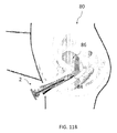
- FIGS. 11A-11H A method of employing a medical diagnostic device 2 , in accordance with an embodiment, is herein sequentially illustrated in FIGS. 11A-11H .
- the medical diagnostic device 2 which in this specific instance is most closely similar to the device 2 A, can be employed to examine the vagina of a female patient 80 , although any of the herein described devices or equivalents could be similarly employed.
- the medical diagnostic device 2 described herein can be used by a patient to perform an self-diagnosis without the need for a medical professional to be physically present during the examination.
- the examination can be performed by the female patient 80 in the patient's home or in private in a medical office.
- the medical diagnostic device 2 can be employed by a medical professional in performing an examination of the female patient 80 .
- the distal end of the medical diagnostic device 2 is inserted in the vagina 82 of the female patient 80 and advanced in the direction depicted by arrow 83 , within the vagina 82 toward the cervix 84 .
- the distal end of the vaginal diagnostic device is positioned near the cervix 84 and before the uterus 86 , as illustrated in FIG. 11B , there is no further advancement of the vaginal diagnostic device 2 .
- the vaginal diagnostic device 2 when the vaginal diagnostic device 2 is suitably positioned within the female patient 80 , the user applies a force to the engagement member 26 using the hand 88 of the user. Because the engagement member 26 is seated within the conical section 28 of the core 16 , the force is transmitted to the core 16 , causing the core 16 to advance axially within the outer sleeve 4 until the conical section 28 of the core 16 is received in the conical section 6 of the outer sleeve 4 . Advancement of the core 16 triggers expansion of the expansion section 10 , thus causing the medical diagnostic device 2 to transition from the closed insertion position to the open deployed position. As illustrated in FIG.
- the diagnostic assembly when the medical diagnostic device 2 is in the open deployed position, the diagnostic assembly extends.
- the diagnostic assembly can include a sample collecting assembly 19 , an imaging device 56 , or a combination of the sample collecting assembly 19 and the imaging device 56 .
- the user of the diagnostic device 2 manipulates (e.g., rotates) the engagement member 26 , which due to the connection between the engagement member 26 and the diagnostic assembly, correspondingly causes the entire diagnostic assembly to rotate.
- the diagnostic assembly is a sample collecting assembly 19 that includes a sample collector 12 .
- the sample collector 12 in the deployed position, the sample collector 12 extends and rotation of the engagement member 36 causes the sample collector 12 to rotate and engage the cervix in order to gather a sample.
- the diagnostic assembly includes an imaging device 56
- the imaging device 56 extends and is also permitted to rotate in order to gather image data.
- the user compresses the conical section 6 of the medical diagnostic device 2 with the user's hand 88 .
- the female 80 applies a force to the spaced locator pads 20 , causing inward depression of the conical section 6 of the outer sleeve 4 .
- This compression of the proximal conical section 7 engages and retracts the core 16 via engagement with the proximal conical portion 28 from the open deployed position to the closed insertion position.
- the stop surface 38 of the outer sleeve 4 positively engages the stop groove 40 of the core 16 to prevent the core 16 from further movement and also from ejecting entirely from the outer sleeve 4 .
- the user 80 moves the medical diagnostic device 2 downward, in the direction of arrow 92 , away from the cervix 84 as illustrated in FIG. 11F .
- the medical diagnostic device 2 is removed from the vagina 82 .
- FIG. 11H when the diagnostic assembly is a sample collecting assembly, following removal of the medical diagnostic device 2 , the patient 80 applies a force to the proximal end of the ejector pin 22 . This force causes the ejector pin 22 to release the sample collector 12 from the ejector pin 22 by advancing the sample collector 12 beyond the distal end of the keyed rotatable hollow shaft 24 .
- the sample collector 12 can be ejected into a sample container 44 .
- This sample container 44 can be sent to a medical professional for analysis.
- the diagnostic assembly includes an imaging device 56 , the image data gathered by the imaging device 56 can be sent to a medical professional for analysis.
- vaginal diagnostic device 2 A including a sample collector 12
- the method can employ any of the previously described embodiments of the medical diagnostic device 2 A, 2 B, 2 C previously described herein.
- the method is described as collecting a vaginal sample, it is to be understood that the herein described medical diagnostic device can collect a sample, image data, or a combination of a sample and image data.
- a method 94 of utilizing a medical diagnostic device includes, at block 96 , inserting a diagnostic assembly axially through a core.
- the diagnostic assembly includes a sample collector coupled to an ejector pin that is inserted axially through a rotatable shaft.
- the diagnostic assembly is an imaging device.
- the diagnostic assembly is both a sample collector and an imaging device.
- the core and diagnostic assembly are inserted axially through the outer sleeve of the medical diagnostic device.
- the distal end of the diagnostic device is positioned within the vagina or other body cavity of the patient.
- the medical diagnostic device is then advanced through the vagina to the cervix.
- the core is repositioned from an insertion position to a deployed position.
- the diagnostic assembly is manipulated to collect a patient sample and/or image data.
- the diagnostic device 200 includes an outer sleeve 204 that is defined by a distal portion 208 , a proximal portion 212 as well as a hollow interior 214 .
- the majority of the outer sleeve 204 , including the distal portion 208 is defined by a substantially tubular configuration having a substantially constant diameter that transitions to the proximal portion 212 , the latter being defined by a tapering or substantially conical shape.
- At least one stop surface 216 is provided along an inner surface of the outer sleeve 204 at the transition between the tubular and conical sections 208 , 212 of the outer sleeve 204 . More specifically, the stop surface 216 can be an axial projection.
- a core 220 is positioned within the hollow interior 214 of the outer sleeve 204 .
- the core 220 according to this embodiment is defined by an elongate tubular member 224 that includes an exterior surface 228 , as well as respective distal and proximal portions 232 , 236 .
- the core 220 further includes a hollow tapering or conical portion 240 extending from the proximal portion 236 of the elongate tubular member 224 and in which the proximal end of the hollow proximal conical portion 240 includes an engagement member 246 , which according to this embodiment is in the form of a knob.
- a pair of stop grooves 244 , 248 are provided in the exterior surface 228 of the core 220 in spaced relation. In an initial position, the stop surface 216 is engaged with a distal stop groove 244 , also as shown in FIG. 13A , which prevents the core 220 from being retracted outwardly beyond a predetermined axial position.
- the diagnostic assembly includes an ejector rod 256 having a proximal end 261 that extends initially from the proximal end 225 of the elongate tubular member 224 and within a recess 241 that is formed in the hollow proximal conical portion 240 .
- the ejector rod 256 is axially movable within the core 220 , the distal end of the core 220 further supporting a sample collecting device 260 .
- the distal end of the core 220 includes at least one keyway 268 that is configured to engage a corresponding number of keys 270 radially extending from a proximal or coupling portion 271 of the sample collecting device 260 .
- the sample collecting device 260 is a brush having a series of circumferentially disposed bristles 276 at its distal end.
- the sampling device 260 is further defined by a shaft 280 disposed between the bristles 276 and the coupling portion 271 that is angled relative to a common primary axis defined by the core 220 and the outer sleeve 204 , when assembled, and as shown in FIG. 13A .
- the shaft could form a curved section relative to the primary axis of the assembly.
- the core 220 is advanced axially toward the distal end of the outer sleeve 204 , which advances the sample collecting device 260 through a formed distal opening of the outer sleeve 204 .
- Axial movement proceeds until the stop surface 216 engages the second spaced stop groove 248 , the latter groove 248 being disposed adjacent the transition of the conical portion 240 of the core 220 .
- the substantially conical sections 212 , 240 of the outer sleeve 204 and core 220 are nested.
- the angled shaft 280 of the sample collecting device 260 better insures the ability of the sample collecting device 260 and more specifically the disposed bristles 271 to engage the surface of the cervix (not shown) in order to obtain a suitable sample through rotation of the core 220 as accessed using the engagement member 246 .
- the proximal end of the sample collecting device 260 includes a coupling portion having a pair of radially disposed keys 286 that are aligned with corresponding keyways 268 at the end of the ejector rod 256 . In this position, the keys 270 and keyways 268 are still engaged within the distal end of the core 220 , thereby retaining the sample collecting device 260 in use.
- the proximal end of the ejector rod 256 is axially advanced by the user (not shown), which advances the coupling portion of the sample collecting device 260 from the core 220 and the outer cavity 204 .
- the formed recess 241 of the hollow conical portion 240 protects inadvertent contact with the projecting end 261 of the ejector rod 256 when the diagnostic device 200 is still in use and prevents premature ejection of the sample collecting device 260 .
- the shoulder above the key is sized according to this specific embodiment so as not to allow passage through the distal end of the outer sleeve 204 .
- the foregoing feature is provided chiefly to insure patient safety.
- sample collecting device 290 is shown in FIG. 14B .
- the sample collecting device 290 is a brush that is defined with angled bristles 294 extending from the distal end of the sample collecting device 290 when in the deployed position.
- this device also includes a coupling portion at a proximal end having a set of keys (or keyways) configured for engaging corresponding keyways formed at the distal end of the core 220 .
- FIGS. 15-18 depicting yet another embodiment of a medical (vaginal) diagnostic device 300 .
- the diagnostic device 300 is defined by an outer sleeve 304 having a distal portion 308 and a proximal portion 312 , as well as a hollow interior 314 .
- the majority of the outer sleeve 304 , including the distal portion 308 is defined by a substantially tubular configuration having a constant diameter that transitions to the proximal portion 312 , the latter being defined by an outwardly tapering or substantially conical shape.
- At least one stop surface 316 in this instance, at least one axial projection is provided along an inner surface of the outer sleeve 304 at the transition between the tubular and conical sections 308 , 312 of the outer sleeve 304 .
- a core 320 (also herein referred to synonymously as an obturator) is positioned within the hollow interior 314 of the outer sleeve 304 . 304 .
- the core 320 according to this embodiment is defined by an elongate tubular member 324 that includes an exterior surface 328 , as well as respective distal and proximal portions 332 , 336 .
- the core 320 further includes a hollow tapering or conical portion 340 that outwardly and radially extends from the proximal portion 336 of the elongate tubular member 324 and in which a proximal end of the hollow proximal conical portion 340 includes an engagement member 346 , which according to this embodiment is a formed knob and in which the hollow proximal conical portion 340 is further defined by a formed recess 341 .
- a pair of stop grooves 344 , 348 are provided in the exterior surface 328 of the core 320 in spaced relation. In an initial position, the stop surface 316 is engaged with a distal stop groove 344 , as shown in FIG. 15 which prevents the core 320 from being retracted beyond a predetermined axial position, as shown.
- the diagnostic assembly includes a rotatable ejector rod 356 having a proximal end 361 that extends initially from the proximal end 325 of the elongate tubular member 324 and the recess 341 of the hollow proximal conical portion 340 .
- An opposing distal end 364 of the ejector rod 356 extends into the distal end of the core 320 and is configured to engage the sample collecting device 360 , such as a brush having a series of distally disposed bristles 376 .
- the sample collecting device 360 includes a proximal or coupling end that includes a pair of keys 370 or other connecting means that engage with corresponding slots or keyways 368 that are formed in the distal end of the core 320 .
- the distal end of the ejector rod 356 is further configured to support an imaging assembly 384 , as shown most specifically in FIG. 18 , including an electronic imager disposed in relation to the bristles 376 of the sample collecting device 360 as well as a plurality of LEDs 388 that are circumferentially disposed as a ring about the imager to provide sufficient illumination of the target of interest.
- the bristles 376 of the sampling device 360 are made from a non-reflective material in order to more efficiently illuminate the target of interest (e.g., cervix) for viewing wherein the imaging assembly includes a wired or wireless connection in order to transmit images.
- the imaging assembly 384 and the illumination assembly 388 can be powered by means of a battery (not shown) using, for example, a USB connection. Alternatively, self-contained power sources can be provided.
- the imaging assembly 384 including the shaft, is prevented from inadvertently retracting from the proximal end of the device 300 by means of a retainer 350 that is disposed between the elongate tubular member 325 of the outer sleeve 304 and the outer surface of the shaft 356 , the retainer 350 having a compressive clamp 354 at a proximal end thereof.
- the core 320 is advanced axially toward the distal end of the outer sleeve 304 , which advances a portion of the sample collecting device 360 , including the bristles 376 , through a formed distal opening of the outer sleeve 304 and further positions the imaging assembly 384 at the distal opening of the outer sleeve 304 .
- axial movement proceeds until the stop surface 316 engages the second spaced stop groove 348 , the latter groove 348 being disposed adjacent the transition of the conical proximal portion 340 of the core 320 .
- the substantially conical sections 312 , 340 of the outer sleeve 304 and the core 320 are nested.
- the core 320 is then rotated using the engagement member 346 to enable the sample collecting device 360 to corresponding rotate about the axis of the core 320 to collect a suitable sample from the wall of the body cavity and in which the sampling operation can be viewed using the imager assembly 384 , the latter assembly being fixed and prevented from rotation by the retainer 350 .
- the ejection of the sample collecting device 360 from the diagnostic device 300 is depicted.
- the outer sleeve is not shown for the sake of clarity.
- the proximal end of the ejector rod 356 is axially advanced toward the distal end of the diagnostic device 300 , which advances the ejector shaft against a shoulder of the sample collecting device 360 and further advances the keys 370 of the coupling portion from the keyways 368 at the distal end of the core 320 .
- the sample collecting device 360 is released from the assembly 300 and deposited in a suitable sample container 44 .
- the recess 341 of the hollow conical portion 340 protects inadvertent contact with the ejector rod 356 when the device 300 is still in use and prevents premature ejection of the sample collecting device 360 .
- FIGS. 19A-19C another retainer version is herein depicted for use with the assembly 300 . Similar parts are herein labeled with the same reference numerals for the sake of clarity. More specifically, the depicted retainer 450 is defined by a hollow and substantially tubular structure having respective distal and proximal ends 453 and 456 as well as a pair of engaging portions 462 adjacent the proximal end 456 that extend radially outward from the tubular structure.
- Each of the engaging members 462 are defined by flexible curved sections that are sized to engage an undercut formed within the recess 341 of the conical portion 340 of the core 320 and compressively engage against the inner surface of the conical section 340 when fitted with the cabling of the imaging assembly being supported by the hollow tubular structure of the retainer 450 .
- the sampling device 360 can be keyed for rotation, as described, when acted upon by the engagement member 346 in the same manner previously described.
- the imaging assembly 384 being secured by the retainer 450 is prevented from rotating.
- the flexible engaging members 462 prevent the imaging assembly 384 from prematurely retracting from assembly 300 and more specifically proximally from the core 320 .
- the number of flexible engaging members can be varied provided the members are capable of providing sufficient radial/torsional force to prevent free axial movement of the imaging assembly 484 .
- ejection can occur based on inward flexion of the retainer 450 in combination with axial movement of the imaging assembly 384 .
Landscapes
- Health & Medical Sciences (AREA)
- Life Sciences & Earth Sciences (AREA)
- Surgery (AREA)
- General Health & Medical Sciences (AREA)
- Public Health (AREA)
- Veterinary Medicine (AREA)
- Pathology (AREA)
- Animal Behavior & Ethology (AREA)
- Molecular Biology (AREA)
- Engineering & Computer Science (AREA)
- Biomedical Technology (AREA)
- Heart & Thoracic Surgery (AREA)
- Medical Informatics (AREA)
- Biophysics (AREA)
- Radiology & Medical Imaging (AREA)
- Physics & Mathematics (AREA)
- Nuclear Medicine, Radiotherapy & Molecular Imaging (AREA)
- Optics & Photonics (AREA)
- Gynecology & Obstetrics (AREA)
- Reproductive Health (AREA)
- Endoscopes (AREA)
Abstract
Description
- 1 device proximal end
- 2 medical diagnostic device
- 2A medical diagnostic device
- 2B medical diagnostic device
- 2C medical diagnostic device
- 3 distal end, diagnostic device
- 4 outer sleeve
- 6 substantially conical section (outer sleeve)
- 8 distal section (outer sleeve)
- 9 hollow interior (outer sleeve)
- 10 expansion section
- 11 fingers, expansion section
- 12 sample collector
- 13 axial cuts
- 14 elastically deformable sheath
- 16 core
- 17 axial cavity, core
- 18 proximal end
- 19 sample collecting assembly
- 20 locator pads
- 22 ejector pin
- 24 hollow rotatable shaft
- 26 engagement member
- 27 distal section, core
- 28 proximal section, core
- 30 recessed center portion
- 31 bristles
- 32 coupling portion
- 34 keyways
- 36 keys
- 38 stop surface
- 40 stop groove
- 42 opening
- 44 sample container
- 52 connection
- 56 imaging device
- 58 computing device
- 80 female patient
- 82 vagina
- 83 arrow
- 84 cervix
- 86 uterus
- 88 hand
- 90 rotation
- 92 arrow
- 94 method
- 96-104 method blocks
- 200 medical diagnostic device
- 204 outer sleeve
- 208 distal portion, outer sleeve
- 212 proximal portion, outer sleeve
- 214 hollow interior
- 216 stop surface
- 220 core
- 221 axial opening, core
- 224 elongate tubular member
- 225 proximal end, elongate tubular member
- 228 exterior surface, core
- 232 distal portion
- 236 proximal portion, elongate tubular member
- 240 tapering or conical section
- 241 recess, proximal conical section
- 244 stop groove, distal
- 246 engagement member
- 248 stop groove
- 256 ejector rod or shaft
- 260 sample collecting device
- 261 proximal end, ejector rod or shaft
- 268 keyways
- 270 keys
- 271 coupling portion
- 276 bristles
- 280 shaft, angled
- 290 sample collecting device
- 294 bristles, angled
- 300 medical diagnostic device
- 304 outer sleeve
- 308 distal portion, outer sleeve
- 312 proximal portion, outer sleeve
- 314 hollow interior, outer sleeve
- 316 stop surface, outer sleeve
- 320 core
- 321 axial opening, core
- 324 elongate tubular member, core
- 325 proximal end, elongate tubular member
- 328 exterior surface, core
- 332 distal portion, elongate tubular member
- 336 proximal portion, elongate tubular member
- 340 hollow tapering or conical portion
- 341 recess, hollow conical portion
- 344 stop groove, distal
- 346 engagement member
- 348 stop groove
- 350 retainer
- 354 compressive clamp
- 356 ejector rod or shaft
- 360 sample collecting device
- 361 proximal end, ejector rod or shaft
- 368 keyways
- 370 keys
- 376 bristles
- 380 shaft
- 384 imaging assembly
- 388 LEDs
- 450 retainer
- 453 distal end, retainer
- 456 proximal end, retainer
- 462 flexible engaging members, retainer
Claims (19)
Priority Applications (1)
| Application Number | Priority Date | Filing Date | Title |
|---|---|---|---|
| US15/136,226 US10433822B2 (en) | 2016-04-22 | 2016-04-22 | System and method for medical diagnostics |
Applications Claiming Priority (1)
| Application Number | Priority Date | Filing Date | Title |
|---|---|---|---|
| US15/136,226 US10433822B2 (en) | 2016-04-22 | 2016-04-22 | System and method for medical diagnostics |
Publications (2)
| Publication Number | Publication Date |
|---|---|
| US20170303903A1 US20170303903A1 (en) | 2017-10-26 |
| US10433822B2 true US10433822B2 (en) | 2019-10-08 |
Family
ID=60089183
Family Applications (1)
| Application Number | Title | Priority Date | Filing Date |
|---|---|---|---|
| US15/136,226 Active 2037-11-05 US10433822B2 (en) | 2016-04-22 | 2016-04-22 | System and method for medical diagnostics |
Country Status (1)
| Country | Link |
|---|---|
| US (1) | US10433822B2 (en) |
Families Citing this family (24)
| Publication number | Priority date | Publication date | Assignee | Title |
|---|---|---|---|---|
| US9913577B2 (en) | 2010-09-28 | 2018-03-13 | Obp Medical Corporation | Speculum |
| US11931012B2 (en) * | 2011-09-02 | 2024-03-19 | Viospex | Vaginal speculum and cervical screening kit |
| US10420538B2 (en) | 2015-02-05 | 2019-09-24 | Obp Medical Corporation | Illuminated surgical retractor |
| US9867602B2 (en) | 2015-02-05 | 2018-01-16 | Obp Medical Corporation | Illuminated surgical retractor |
| ES2968069T3 (en) | 2015-06-03 | 2024-05-07 | Obp Surgical Corp | Retractor |
| US10939899B2 (en) | 2015-06-03 | 2021-03-09 | Obp Medical Corporation | End cap assembly for retractor and other medical devices |
| US10881387B2 (en) | 2015-06-03 | 2021-01-05 | Obp Medical Corporation | Retractor |
| US10722621B2 (en) | 2016-07-11 | 2020-07-28 | Obp Medical Corporation | Illuminated suction device |
| WO2019018470A1 (en) | 2017-07-18 | 2019-01-24 | Obp Medical Corporation | Minimally invasive no touch (mint) procedure for harvesting the great saphenous vein (gsv) and venous hydrodissector and retractor for use during the mint procedure |
| US10278572B1 (en) | 2017-10-19 | 2019-05-07 | Obp Medical Corporation | Speculum |
| US10799229B2 (en) | 2018-02-20 | 2020-10-13 | Obp Medical Corporation | Illuminated medical devices |
| WO2019164795A1 (en) | 2018-02-20 | 2019-08-29 | Obp Medical Corporation | Illuminated medical devices |
| USD911521S1 (en) | 2019-02-19 | 2021-02-23 | Obp Medical Corporation | Handle for medical devices including surgical retractors |
| USD904607S1 (en) | 2019-05-07 | 2020-12-08 | Obp Medical Corporation | Nasal retractor |
| CN110664365A (en) * | 2019-10-22 | 2020-01-10 | 上海法路源医疗器械有限公司 | Accurate screening system for cervical cancer |
| US10959609B1 (en) | 2020-01-31 | 2021-03-30 | Obp Medical Corporation | Illuminated suction device |
| US10966702B1 (en) | 2020-02-25 | 2021-04-06 | Obp Medical Corporation | Illuminated dual-blade retractor |
| US20230103245A1 (en) * | 2020-03-04 | 2023-03-30 | Anqing Medical Co., Ltd | Rigid endoscope |
| US20220378286A1 (en) * | 2021-05-26 | 2022-12-01 | Virginia Commonwealth University | Vaginal examination device and methods of use thereof |
| CA3222658A1 (en) * | 2021-06-14 | 2022-12-22 | Avnesh THAKOR | Devices, systems, and methods for self-collection of biological samples |
| GB2617789A (en) * | 2021-10-07 | 2023-10-18 | Lbn Innovations Ltd | Cervical sampling brush |
| GB2611108B (en) * | 2021-10-07 | 2023-10-25 | Lbn Innovations Ltd | Cervical sampling brush, cervical inspection device, and method of control thereof |
| USD1021130S1 (en) | 2022-06-13 | 2024-04-02 | Teal Health, Inc. | Sample collection device |
| US20230414207A1 (en) * | 2022-06-28 | 2023-12-28 | Brent Harris | Devices and methods with expandable brush for cervical and anal self-collecting specimens |
Citations (26)
| Publication number | Priority date | Publication date | Assignee | Title |
|---|---|---|---|---|
| US4784158A (en) * | 1987-08-21 | 1988-11-15 | Okimoto Paul M | Vaginal testing applicator and method |
| US4788985A (en) | 1982-09-30 | 1988-12-06 | Medtest Corporation | Device for cell sampling in a body cavity |
| US5445164A (en) * | 1993-05-11 | 1995-08-29 | Gynetech, Inc. | Cervical tissue sampling device |
| US5989184A (en) | 1997-04-04 | 1999-11-23 | Medtech Research Corporation | Apparatus and method for digital photography useful in cervical cancer detection |
| US6088612A (en) | 1997-04-04 | 2000-07-11 | Medtech Research Corporation | Method and apparatus for reflective glare removal in digital photography useful in cervical cancer detection |
| US6156006A (en) | 1997-10-17 | 2000-12-05 | Circon Corporation | Medical instrument system for piercing through tissue |
| US6277067B1 (en) | 1997-04-04 | 2001-08-21 | Kerry L. Blair | Method and portable colposcope useful in cervical cancer detection |
| US6293952B1 (en) | 1997-07-31 | 2001-09-25 | Circon Corporation | Medical instrument system for piercing through tissue |
| US6352513B1 (en) | 1999-06-25 | 2002-03-05 | Ampersand Medical Corporation | Personal cervical cell collector |
| US6514224B1 (en) * | 1999-01-04 | 2003-02-04 | Merete Management Gmbh | Device for taking a biological or cytological smear |
| US20030225313A1 (en) | 2002-06-04 | 2003-12-04 | German Borodulin | Vaginal speculum with insertable one-lens colposcope |
| US20040068162A1 (en) | 2002-07-01 | 2004-04-08 | Vaclav Kirsner | Apparatus and method of personal screening for cervical cancer conditions in vivo |
| US20050020937A1 (en) | 2003-03-31 | 2005-01-27 | West Virginia University | Method for detecting pathogenic agents |
| US6896653B1 (en) | 2002-03-07 | 2005-05-24 | Science For Medical Advocates, Inc. | Personal pelvic viewer |
| US6926677B2 (en) | 1999-11-23 | 2005-08-09 | Michael Owen Richards | Cellular collection apparatus and method |
| US20050215858A1 (en) | 2002-03-07 | 2005-09-29 | Vail William B Iii | Tubular personal pelvic viewers |
| US20080188769A1 (en) | 2007-02-07 | 2008-08-07 | Li-Cheng Lu | Foldable Brush Self-sampling Device |
| US20090143646A1 (en) | 2002-03-07 | 2009-06-04 | Vail Iii William Banning | Tubular personal pelvic viewers |
| US20100016668A1 (en) | 2006-07-24 | 2010-01-21 | Wave Group Ltd. | Medical device for discreetly performing a routine vaginal examination |
| US20110190579A1 (en) | 2009-09-28 | 2011-08-04 | Witold Andrew Ziarno | Intravaginal monitoring device |
| US20120157767A1 (en) | 2010-12-20 | 2012-06-21 | Milagen, Inc. | Digital Cerviscopy Device and Applications |
| US20130211288A1 (en) * | 2009-08-21 | 2013-08-15 | Rovers Holding B.V. | Sampling device and method for preparing the same |
| US20140088364A1 (en) | 2012-09-26 | 2014-03-27 | William Banning Vail, III | Slotted elongated tubular shaped personal pelvic viewer for simultaneously examining the paraurethral sponge, the skene's glands, and the urethra |
| US20140257098A1 (en) | 2013-03-05 | 2014-09-11 | Giuseppe Del Priore | Systems and methods for detection of cancer in women |
| US20170042518A1 (en) * | 2015-08-10 | 2017-02-16 | Solocell Corp. | Medical apparatus for sampling cervical tissue |
| US20170319317A1 (en) * | 2014-10-28 | 2017-11-09 | Imv Technologies | Apparatus for vaginal penetration of animals comprising a viewing system, in particular for locating the cervix of the uterus |
-
2016
- 2016-04-22 US US15/136,226 patent/US10433822B2/en active Active
Patent Citations (32)
| Publication number | Priority date | Publication date | Assignee | Title |
|---|---|---|---|---|
| US4788985A (en) | 1982-09-30 | 1988-12-06 | Medtest Corporation | Device for cell sampling in a body cavity |
| US4784158A (en) * | 1987-08-21 | 1988-11-15 | Okimoto Paul M | Vaginal testing applicator and method |
| US5445164A (en) * | 1993-05-11 | 1995-08-29 | Gynetech, Inc. | Cervical tissue sampling device |
| US5989184A (en) | 1997-04-04 | 1999-11-23 | Medtech Research Corporation | Apparatus and method for digital photography useful in cervical cancer detection |
| US6088612A (en) | 1997-04-04 | 2000-07-11 | Medtech Research Corporation | Method and apparatus for reflective glare removal in digital photography useful in cervical cancer detection |
| US6277067B1 (en) | 1997-04-04 | 2001-08-21 | Kerry L. Blair | Method and portable colposcope useful in cervical cancer detection |
| US6293952B1 (en) | 1997-07-31 | 2001-09-25 | Circon Corporation | Medical instrument system for piercing through tissue |
| US6156006A (en) | 1997-10-17 | 2000-12-05 | Circon Corporation | Medical instrument system for piercing through tissue |
| US6514224B1 (en) * | 1999-01-04 | 2003-02-04 | Merete Management Gmbh | Device for taking a biological or cytological smear |
| US6352513B1 (en) | 1999-06-25 | 2002-03-05 | Ampersand Medical Corporation | Personal cervical cell collector |
| US20020087096A1 (en) * | 1999-06-25 | 2002-07-04 | Molecular Diagnostics, Inc. | Personal cervical cell collector |
| US6926677B2 (en) | 1999-11-23 | 2005-08-09 | Michael Owen Richards | Cellular collection apparatus and method |
| US6896653B1 (en) | 2002-03-07 | 2005-05-24 | Science For Medical Advocates, Inc. | Personal pelvic viewer |
| US20050215858A1 (en) | 2002-03-07 | 2005-09-29 | Vail William B Iii | Tubular personal pelvic viewers |
| US20090143646A1 (en) | 2002-03-07 | 2009-06-04 | Vail Iii William Banning | Tubular personal pelvic viewers |
| US20030225313A1 (en) | 2002-06-04 | 2003-12-04 | German Borodulin | Vaginal speculum with insertable one-lens colposcope |
| US6712761B2 (en) | 2002-06-04 | 2004-03-30 | German Borodulin | Combination of a vaginal speculum with a single-lens colposcope |
| US20040068162A1 (en) | 2002-07-01 | 2004-04-08 | Vaclav Kirsner | Apparatus and method of personal screening for cervical cancer conditions in vivo |
| US20050020937A1 (en) | 2003-03-31 | 2005-01-27 | West Virginia University | Method for detecting pathogenic agents |
| US20100016668A1 (en) | 2006-07-24 | 2010-01-21 | Wave Group Ltd. | Medical device for discreetly performing a routine vaginal examination |
| US20080188769A1 (en) | 2007-02-07 | 2008-08-07 | Li-Cheng Lu | Foldable Brush Self-sampling Device |
| US20130211288A1 (en) * | 2009-08-21 | 2013-08-15 | Rovers Holding B.V. | Sampling device and method for preparing the same |
| US20140180165A9 (en) | 2009-08-21 | 2014-06-26 | Rovers Holding B.V. | Sampling device and method for preparing the same |
| US20110190581A1 (en) | 2009-09-28 | 2011-08-04 | Bennett James D | Intravaginal monitoring support architecture |
| US8679013B2 (en) | 2009-09-28 | 2014-03-25 | Witold Andrew Ziarno | Intravaginal monitoring device |
| US8679014B2 (en) | 2009-09-28 | 2014-03-25 | James D. Bennett | Network supporting intravaginal monitoring device |
| US20110190579A1 (en) | 2009-09-28 | 2011-08-04 | Witold Andrew Ziarno | Intravaginal monitoring device |
| US20120157767A1 (en) | 2010-12-20 | 2012-06-21 | Milagen, Inc. | Digital Cerviscopy Device and Applications |
| US20140088364A1 (en) | 2012-09-26 | 2014-03-27 | William Banning Vail, III | Slotted elongated tubular shaped personal pelvic viewer for simultaneously examining the paraurethral sponge, the skene's glands, and the urethra |
| US20140257098A1 (en) | 2013-03-05 | 2014-09-11 | Giuseppe Del Priore | Systems and methods for detection of cancer in women |
| US20170319317A1 (en) * | 2014-10-28 | 2017-11-09 | Imv Technologies | Apparatus for vaginal penetration of animals comprising a viewing system, in particular for locating the cervix of the uterus |
| US20170042518A1 (en) * | 2015-08-10 | 2017-02-16 | Solocell Corp. | Medical apparatus for sampling cervical tissue |
Non-Patent Citations (2)
| Title |
|---|
| Evalyn® Brush; Rovers Medical Devices; http://www.roversmedicaldevices.com/cell-sampling-devices/evalyn-brush/?lang=en; 3 pages. |
| Self Smear Test Kit to Perform Smear Test at Home; Hakan Gürsu; http://www.tuvie.com/self-smear-test-kit-to-perform-smear-test-at-home-by-hakan-gursu/; 6 pages. |
Also Published As
| Publication number | Publication date |
|---|---|
| US20170303903A1 (en) | 2017-10-26 |
Similar Documents
| Publication | Publication Date | Title |
|---|---|---|
| US10433822B2 (en) | System and method for medical diagnostics | |
| US10004392B2 (en) | Device and method for conducting a pap smear test | |
| US5158563A (en) | Single-operator hemorrhoid ligator | |
| JP6422891B2 (en) | Otoscope | |
| RU2566918C2 (en) | Tube casing for medical endoscopic device and medical endoscopic device containing it | |
| US20090163943A1 (en) | Multi-purpose tool for minor surgery | |
| US11849925B1 (en) | Vagina probe with brush | |
| EP3863498B1 (en) | Digital endoscope | |
| JP2016506785A (en) | Otoscope | |
| EP3801406A1 (en) | Placing and removing surgical stents | |
| US11957322B2 (en) | Personal cervical cell collection device, kit and method | |
| US6402700B1 (en) | Pap smear apparatus and method | |
| IL267194B2 (en) | Brush biopsy device, kit and method | |
| US20150182205A1 (en) | Device and method for conducting a pap smear test | |
| US20210161375A1 (en) | Digital Colposcope for Self-Examination | |
| CN209808293U (en) | Protective sleeve for biopsy plug of digestive endoscopy | |
| KR101898525B1 (en) | Endoscope | |
| KR101902861B1 (en) | Catheter | |
| US20230337903A1 (en) | Coaxial dilation speculum apparatus and method to access, illuminate, and visualize. | |
| EP4164469B1 (en) | Proctoscope | |
| CN118139585A (en) | Cervical inspection apparatus, control method thereof and cervical sampling brush | |
| OA20871A (en) | Medical insertion device. | |
| WO2018187235A1 (en) | Low-profile videoscopic speculum with working port | |
| US20230148856A1 (en) | Vaginal speculum and cervical screening kit | |
| WO2022150439A1 (en) | Examination scope with tissue sample collection brush |
Legal Events
| Date | Code | Title | Description |
|---|---|---|---|
| AS | Assignment |
Owner name: WELCH ALLYN, INC., NEW YORK Free format text: ASSIGNMENT OF ASSIGNORS INTEREST;ASSIGNORS:DE KONING, LEZANNE;VIVENZIO, ROBERT L.;LIA, RAYMOND A.;AND OTHERS;SIGNING DATES FROM 20160616 TO 20160621;REEL/FRAME:038964/0500 |
|
| AS | Assignment |
Owner name: JPMORGAN CHASE BANK, N.A., AS COLLATERAL AGENT, ILLINOIS Free format text: SECURITY AGREEMENT;ASSIGNORS:HILL-ROM SERVICES, INC.;ASPEN SURGICAL PRODUCTS, INC.;ALLEN MEDICAL SYSTEMS, INC.;AND OTHERS;REEL/FRAME:040145/0445 Effective date: 20160921 Owner name: JPMORGAN CHASE BANK, N.A., AS COLLATERAL AGENT, IL Free format text: SECURITY AGREEMENT;ASSIGNORS:HILL-ROM SERVICES, INC.;ASPEN SURGICAL PRODUCTS, INC.;ALLEN MEDICAL SYSTEMS, INC.;AND OTHERS;REEL/FRAME:040145/0445 Effective date: 20160921 |
|
| STPP | Information on status: patent application and granting procedure in general |
Free format text: RESPONSE TO NON-FINAL OFFICE ACTION ENTERED AND FORWARDED TO EXAMINER |
|
| STPP | Information on status: patent application and granting procedure in general |
Free format text: NOTICE OF ALLOWANCE MAILED -- APPLICATION RECEIVED IN OFFICE OF PUBLICATIONS |
|
| STPP | Information on status: patent application and granting procedure in general |
Free format text: PUBLICATIONS -- ISSUE FEE PAYMENT VERIFIED |
|
| AS | Assignment |
Owner name: MORTARA INSTRUMENT, INC., WISCONSIN Free format text: RELEASE BY SECURED PARTY;ASSIGNOR:JPMORGAN CHASE BANK, N.A.;REEL/FRAME:050254/0513 Effective date: 20190830 Owner name: ALLEN MEDICAL SYSTEMS, INC., ILLINOIS Free format text: RELEASE BY SECURED PARTY;ASSIGNOR:JPMORGAN CHASE BANK, N.A.;REEL/FRAME:050254/0513 Effective date: 20190830 Owner name: WELCH ALLYN, INC., NEW YORK Free format text: RELEASE BY SECURED PARTY;ASSIGNOR:JPMORGAN CHASE BANK, N.A.;REEL/FRAME:050254/0513 Effective date: 20190830 Owner name: HILL-ROM COMPANY, INC., ILLINOIS Free format text: RELEASE BY SECURED PARTY;ASSIGNOR:JPMORGAN CHASE BANK, N.A.;REEL/FRAME:050254/0513 Effective date: 20190830 Owner name: ANODYNE MEDICAL DEVICE, INC., FLORIDA Free format text: RELEASE BY SECURED PARTY;ASSIGNOR:JPMORGAN CHASE BANK, N.A.;REEL/FRAME:050254/0513 Effective date: 20190830 Owner name: HILL-ROM SERVICES, INC., ILLINOIS Free format text: RELEASE BY SECURED PARTY;ASSIGNOR:JPMORGAN CHASE BANK, N.A.;REEL/FRAME:050254/0513 Effective date: 20190830 Owner name: VOALTE, INC., FLORIDA Free format text: RELEASE BY SECURED PARTY;ASSIGNOR:JPMORGAN CHASE BANK, N.A.;REEL/FRAME:050254/0513 Effective date: 20190830 Owner name: HILL-ROM, INC., ILLINOIS Free format text: RELEASE BY SECURED PARTY;ASSIGNOR:JPMORGAN CHASE BANK, N.A.;REEL/FRAME:050254/0513 Effective date: 20190830 Owner name: MORTARA INSTRUMENT SERVICES, INC., WISCONSIN Free format text: RELEASE BY SECURED PARTY;ASSIGNOR:JPMORGAN CHASE BANK, N.A.;REEL/FRAME:050254/0513 Effective date: 20190830 |
|
| AS | Assignment |
Owner name: JPMORGAN CHASE BANK, N.A., ILLINOIS Free format text: SECURITY AGREEMENT;ASSIGNORS:HILL-ROM HOLDINGS, INC.;HILL-ROM, INC.;HILL-ROM SERVICES, INC.;AND OTHERS;REEL/FRAME:050260/0644 Effective date: 20190830 |
|
| STCF | Information on status: patent grant |
Free format text: PATENTED CASE |
|
| AS | Assignment |
Owner name: HILL-ROM HOLDINGS, INC., ILLINOIS Free format text: RELEASE OF SECURITY INTEREST AT REEL/FRAME 050260/0644;ASSIGNOR:JPMORGAN CHASE BANK, N.A.;REEL/FRAME:058517/0001 Effective date: 20211213 Owner name: BARDY DIAGNOSTICS, INC., ILLINOIS Free format text: RELEASE OF SECURITY INTEREST AT REEL/FRAME 050260/0644;ASSIGNOR:JPMORGAN CHASE BANK, N.A.;REEL/FRAME:058517/0001 Effective date: 20211213 Owner name: VOALTE, INC., FLORIDA Free format text: RELEASE OF SECURITY INTEREST AT REEL/FRAME 050260/0644;ASSIGNOR:JPMORGAN CHASE BANK, N.A.;REEL/FRAME:058517/0001 Effective date: 20211213 Owner name: HILL-ROM, INC., ILLINOIS Free format text: RELEASE OF SECURITY INTEREST AT REEL/FRAME 050260/0644;ASSIGNOR:JPMORGAN CHASE BANK, N.A.;REEL/FRAME:058517/0001 Effective date: 20211213 Owner name: WELCH ALLYN, INC., NEW YORK Free format text: RELEASE OF SECURITY INTEREST AT REEL/FRAME 050260/0644;ASSIGNOR:JPMORGAN CHASE BANK, N.A.;REEL/FRAME:058517/0001 Effective date: 20211213 Owner name: ALLEN MEDICAL SYSTEMS, INC., ILLINOIS Free format text: RELEASE OF SECURITY INTEREST AT REEL/FRAME 050260/0644;ASSIGNOR:JPMORGAN CHASE BANK, N.A.;REEL/FRAME:058517/0001 Effective date: 20211213 Owner name: HILL-ROM SERVICES, INC., ILLINOIS Free format text: RELEASE OF SECURITY INTEREST AT REEL/FRAME 050260/0644;ASSIGNOR:JPMORGAN CHASE BANK, N.A.;REEL/FRAME:058517/0001 Effective date: 20211213 Owner name: BREATHE TECHNOLOGIES, INC., CALIFORNIA Free format text: RELEASE OF SECURITY INTEREST AT REEL/FRAME 050260/0644;ASSIGNOR:JPMORGAN CHASE BANK, N.A.;REEL/FRAME:058517/0001 Effective date: 20211213 |
|
| MAFP | Maintenance fee payment |
Free format text: PAYMENT OF MAINTENANCE FEE, 4TH YEAR, LARGE ENTITY (ORIGINAL EVENT CODE: M1551); ENTITY STATUS OF PATENT OWNER: LARGE ENTITY Year of fee payment: 4 |