EP3284884B1 - Method for determining the distance between two presence nodes. - Google Patents
Method for determining the distance between two presence nodes. Download PDFInfo
- Publication number
- EP3284884B1 EP3284884B1 EP17195325.0A EP17195325A EP3284884B1 EP 3284884 B1 EP3284884 B1 EP 3284884B1 EP 17195325 A EP17195325 A EP 17195325A EP 3284884 B1 EP3284884 B1 EP 3284884B1
- Authority
- EP
- European Patent Office
- Prior art keywords
- tool
- power tool
- node
- message
- presence node
- Prior art date
- Legal status (The legal status is an assumption and is not a legal conclusion. Google has not performed a legal analysis and makes no representation as to the accuracy of the status listed.)
- Active
Links
- 238000000034 method Methods 0.000 title claims description 46
- 230000004044 response Effects 0.000 claims description 40
- 238000013475 authorization Methods 0.000 claims description 33
- 238000004891 communication Methods 0.000 claims description 33
- 230000002265 prevention Effects 0.000 claims description 19
- 230000005540 biological transmission Effects 0.000 claims description 17
- 238000004590 computer program Methods 0.000 claims description 11
- 238000012545 processing Methods 0.000 claims description 10
- 238000010276 construction Methods 0.000 description 10
- 230000008901 benefit Effects 0.000 description 8
- 230000015654 memory Effects 0.000 description 7
- 238000010586 diagram Methods 0.000 description 6
- 238000005259 measurement Methods 0.000 description 5
- 230000009471 action Effects 0.000 description 4
- 238000000059 patterning Methods 0.000 description 4
- 239000004065 semiconductor Substances 0.000 description 3
- 238000004364 calculation method Methods 0.000 description 2
- 238000005516 engineering process Methods 0.000 description 2
- 238000005562 fading Methods 0.000 description 2
- 238000012546 transfer Methods 0.000 description 2
- 238000010719 annulation reaction Methods 0.000 description 1
- 230000006399 behavior Effects 0.000 description 1
- 230000008859 change Effects 0.000 description 1
- 230000000295 complement effect Effects 0.000 description 1
- 230000001934 delay Effects 0.000 description 1
- 230000000694 effects Effects 0.000 description 1
- 239000000446 fuel Substances 0.000 description 1
- 230000006870 function Effects 0.000 description 1
- 230000000977 initiatory effect Effects 0.000 description 1
- 230000002452 interceptive effect Effects 0.000 description 1
- 230000008520 organization Effects 0.000 description 1
- 238000009418 renovation Methods 0.000 description 1
- 230000011664 signaling Effects 0.000 description 1
Images


Classifications
-
- B—PERFORMING OPERATIONS; TRANSPORTING
- B25—HAND TOOLS; PORTABLE POWER-DRIVEN TOOLS; MANIPULATORS
- B25F—COMBINATION OR MULTI-PURPOSE TOOLS NOT OTHERWISE PROVIDED FOR; DETAILS OR COMPONENTS OF PORTABLE POWER-DRIVEN TOOLS NOT PARTICULARLY RELATED TO THE OPERATIONS PERFORMED AND NOT OTHERWISE PROVIDED FOR
- B25F5/00—Details or components of portable power-driven tools not particularly related to the operations performed and not otherwise provided for
-
- G—PHYSICS
- G05—CONTROLLING; REGULATING
- G05B—CONTROL OR REGULATING SYSTEMS IN GENERAL; FUNCTIONAL ELEMENTS OF SUCH SYSTEMS; MONITORING OR TESTING ARRANGEMENTS FOR SUCH SYSTEMS OR ELEMENTS
- G05B19/00—Programme-control systems
- G05B19/02—Programme-control systems electric
- G05B19/18—Numerical control [NC], i.e. automatically operating machines, in particular machine tools, e.g. in a manufacturing environment, so as to execute positioning, movement or co-ordinated operations by means of programme data in numerical form
- G05B19/406—Numerical control [NC], i.e. automatically operating machines, in particular machine tools, e.g. in a manufacturing environment, so as to execute positioning, movement or co-ordinated operations by means of programme data in numerical form characterised by monitoring or safety
-
- G—PHYSICS
- G07—CHECKING-DEVICES
- G07C—TIME OR ATTENDANCE REGISTERS; REGISTERING OR INDICATING THE WORKING OF MACHINES; GENERATING RANDOM NUMBERS; VOTING OR LOTTERY APPARATUS; ARRANGEMENTS, SYSTEMS OR APPARATUS FOR CHECKING NOT PROVIDED FOR ELSEWHERE
- G07C3/00—Registering or indicating the condition or the working of machines or other apparatus, other than vehicles
- G07C3/02—Registering or indicating working or idle time only
- G07C3/04—Registering or indicating working or idle time only using counting means or digital clocks
-
- G—PHYSICS
- G07—CHECKING-DEVICES
- G07C—TIME OR ATTENDANCE REGISTERS; REGISTERING OR INDICATING THE WORKING OF MACHINES; GENERATING RANDOM NUMBERS; VOTING OR LOTTERY APPARATUS; ARRANGEMENTS, SYSTEMS OR APPARATUS FOR CHECKING NOT PROVIDED FOR ELSEWHERE
- G07C9/00—Individual registration on entry or exit
- G07C9/00174—Electronically operated locks; Circuits therefor; Nonmechanical keys therefor, e.g. passive or active electrical keys or other data carriers without mechanical keys
- G07C9/00309—Electronically operated locks; Circuits therefor; Nonmechanical keys therefor, e.g. passive or active electrical keys or other data carriers without mechanical keys operated with bidirectional data transmission between data carrier and locks
-
- G—PHYSICS
- G05—CONTROLLING; REGULATING
- G05B—CONTROL OR REGULATING SYSTEMS IN GENERAL; FUNCTIONAL ELEMENTS OF SUCH SYSTEMS; MONITORING OR TESTING ARRANGEMENTS FOR SUCH SYSTEMS OR ELEMENTS
- G05B2219/00—Program-control systems
- G05B2219/30—Nc systems
- G05B2219/32—Operator till task planning
- G05B2219/32128—Gui graphical user interface
-
- G—PHYSICS
- G07—CHECKING-DEVICES
- G07C—TIME OR ATTENDANCE REGISTERS; REGISTERING OR INDICATING THE WORKING OF MACHINES; GENERATING RANDOM NUMBERS; VOTING OR LOTTERY APPARATUS; ARRANGEMENTS, SYSTEMS OR APPARATUS FOR CHECKING NOT PROVIDED FOR ELSEWHERE
- G07C2209/00—Indexing scheme relating to groups G07C9/00 - G07C9/38
- G07C2209/08—With time considerations, e.g. temporary activation, valid time window or time limitations
-
- G—PHYSICS
- G07—CHECKING-DEVICES
- G07C—TIME OR ATTENDANCE REGISTERS; REGISTERING OR INDICATING THE WORKING OF MACHINES; GENERATING RANDOM NUMBERS; VOTING OR LOTTERY APPARATUS; ARRANGEMENTS, SYSTEMS OR APPARATUS FOR CHECKING NOT PROVIDED FOR ELSEWHERE
- G07C2209/00—Indexing scheme relating to groups G07C9/00 - G07C9/38
- G07C2209/60—Indexing scheme relating to groups G07C9/00174 - G07C9/00944
- G07C2209/63—Comprising locating means for detecting the position of the data carrier, i.e. within the vehicle or within a certain distance from the vehicle
-
- G—PHYSICS
- G08—SIGNALLING
- G08B—SIGNALLING OR CALLING SYSTEMS; ORDER TELEGRAPHS; ALARM SYSTEMS
- G08B13/00—Burglar, theft or intruder alarms
- G08B13/02—Mechanical actuation
- G08B13/14—Mechanical actuation by lifting or attempted removal of hand-portable articles
- G08B13/1409—Mechanical actuation by lifting or attempted removal of hand-portable articles for removal detection of electrical appliances by detecting their physical disconnection from an electrical system, e.g. using a switch incorporated in the plug connector
- G08B13/1418—Removal detected by failure in electrical connection between the appliance and a control centre, home control panel or a power supply
Definitions
- the present disclosure relates to a method in a first presence node adapted for determining the distance between said first presence node and a second presence node in a wireless communication network, this method being used in a method for enabling unlocking and locking of a tool.
- a crane may represent a large capital value, but it is rather unpractical for the simple thief or the regular criminal organization to steal a crane.
- the power tool is easy to carry away and may represent a significant value on a market, or may be used for other criminal activities. This is a vast problem for construction companies, which power tools is being stolen or just disappears from construction sites. The lost tools costs money to replace drives insurance costs, and delays planned work.
- a method in a power tool for enabling unlocking and locking of the power tool for prevention of unauthorized use, the method comprising: receiving an unlock message to a control unit, the message including an instruction to unlock the tool, unlocking the power tool according to the instruction by the control unit via an actuator unit, counting an authorization time period from reception of the first message to the control unit by a counter, wherein when the counted authorization time period exceed a predetermined threshold, locking the power tool by the control unit via the actuator unit, thereby enabling prevention of unauthorized use of the power tool by remote unlocking and locking.
- a method in a tool control node for enabling unlocking and locking of a tool for prevention of unauthorized use, the method comprising transmitting an unlock message to the tool, the message including an instruction to unlock the tool, counting an authorization time period from transmission of the unlock message to the tool, wherein when the counted authorization time period exceed a predetermined threshold, transmitting of a lock message including an instruction to lock the tool, thereby enabling prevention of unauthorized use of the tool by remote unlocking and locking.
- a power tool adopted to enable unlocking and locking of the power tool for prevention of unauthorized use, the power tool adopted to receive an unlock message to a control unit, the message including an instruction to unlock the tool, unlock the power tool according to the instruction by the control unit via an actuator unit, count an authorization time period from reception of the first message to the control unit by a counter, wherein when the counted authorization time period exceed a predetermined threshold, lock the power tool by the control unit via the actuator unit, thereby enabling prevention of unauthorized use of the power tool by remote unlocking and locking.
- the actuator unit is at least one of electrical switch, mechanical lock and semiconductor based switch.
- the counter is restarted, such that the power tool remains unlocked.
- the unlock message includes a first key, wherein, the first key is required by the control unit for authorization of the message.
- the drive unit requires at least one of the first key or a second key from the control unit, for enabling of the drive unit.
- a lock message is received by the control unit, the lock message including an instruction to lock the tool, wherein the tool is locked by the control unit via the actuator unit.
- a position message including an alert signal is received by the control unit, the position message including an instruction to repeatedly transmit a response signal as a response to the alert signal, thereby enabling positioning of the tool.
- the communication with the tool is encrypted.
- the tool has a physical tamper protection.
- the positioning of the tool is instead made by the tool control unit.
- the message triggers the control unit to transmit a signal requesting response signals from presence nodes nearby followed by receiving response signals to the control unit from presence nodes nearby and thereby enabling positioning of the tool.
- a power tool control unit adopted to enable unlocking and locking of a tool for prevention of unauthorized use is adopted to:
- the power tool control unit can further be configured to sound and transmit an alarm if said tool leaves the predetermined area.
- a solution is provided to avoid theft of power tools and other capital intensive machineries related to construction sites.
- a lock which is remotely controlled. Only when a user is authorized by the owner of the tool, the tool is unlocked. The tool may be unlocked for a specific period of time. The tool may further be unlocked within a specific geographical or a specific volume. An unlock message may be transmitted from a tool control node, which instructs the power tool to be unlocked. The power tool is then unlocked and fully usable for a certain time period, before the time period has passed, a new unlock message must be received by the power tool, otherwise it will be locked for further usage.
- the tool may for some reason want to revoke an authorization from a user to use the tool, for example if an invoice is not paid for. Than may the tool owner transmit a lock message to the tool, such it becomes unusable.
- the tool owner may delegate a right to transmit unlock and lock messages to an intermediate, a presence node.
- An example may be the tool rental company delegating to a site manager. Such right may also be revoked.
- FIG. 1 shows a block diagram with a power tool 100, a tool control node 110 for controlling power tools 100 and a presence node 120 for handling of delegated controlling of power tools 100.
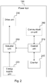
- Fig. 2 shows a block diagram of the tool 100.
- the tool includes a control unit 210 for controlling unlocking and locking of the power tool 100 and other actions.
- the power tool 100 further includes a counter 240 for counting of time.
- the power tool 100 further includes an actuator unit 250 for unlocking and locking of the power tool 100.
- the power tool may also include an energy supply unit 220, a drive unit 230 and a communication unit 260 for reception and transmission of messages.
- Power tool may also be denoted “device”, appliances, powered machine, not limiting to other similar suitable terms. Appliances may include washer, dryer, dishwasher, heat pump, stove, oven, microwave, not limiting to other appliances used in a home or office. Tool control node may also be denoted “remote node” not limiting to other similar suitable terms. Presence node may also be denoted “mobile node” not limiting to other similar suitable terms.
- a few examples of the tool control node 110 may be, a server in a communications network, a virtual server in a communications network, a mobile phone or an application installed on a mobile phone, a PDA (Personal Digital assistant) or an application installed on a PDA, not limiting to other similar nodes.
- a few examples of a presence node 120 may be a mobile phone or an application installed on a mobile phone, a PDA (Personal Digital assistant) or an application installed on a PDA, a gateway, access switch, access router, WLAN access point (Wireless Local Area Network) not limiting to other similar nodes.
- the term “unlock” may also be denoted “enable”, and the term “lock” may also be denoted “disabled”.
- Fig. 3 shows a method in a power tool 100 for enabling unlocking and locking of the power tool for prevention of unauthorized use.
- the method comprises receiving S100 an unlock message to a control unit 210, the message including an instruction to unlock the tool 100.
- the method further comprises unlocking S110 the power tool 100 according to the instruction by the control unit 210 via an actuator unit 250.
- the method further comprises counting S120 an authorization time period from reception of the first message to the control unit 210 by a counter 230, wherein when the counted authorization time period exceed a predetermined threshold, the power tool 100 is locked S130 by the control unit (210) via the actuator unit (250), thereby enabling prevention of unauthorized use of the power tool (100) by remote unlocking and locking.
- the unlock message may come from a tool control node 110.
- the message may be carried via wireless radio communication, for example such as WiFi according to IEEE 802.11 (Institute of Electrical and Electronics Engineers), RFID (Radio-frequency identification), Bluetooth, not limiting to other similar communication methods.
- Protocols used for carrying the message may be Ethernet, TCP/UDP/IP (Transmission Control Protocol/User Datagram Protocol/Internet Protocol).
- SMTP Simple Mail Transfer Protocol
- SMS/MMS Short Message Service / Multimedia Messaging Service
- HTTP/HTTPS Hypertext Transfer Protocol/Secure
- SIP/SIPS Session Initiation Protocol/Secure
- the message with the unlock instruction may also include other information, such as a time stamp, or the length of the authorization time period, not limiting to other information.
- the authorization time period may be a time period during which the power tool 100 may be unlocked and prepared for normal operation. During the authorization time period, the power tool 100 may be outside radio contact with for example the tool control node 110.
- the counter 230 counts the authorization time period, such when the authorization time period exceeds the predetermined threshold the power tool 100 is locked.
- the threshold may be adjusted, for example by manually setting a different value, or by reception of a different value via the unlock message or the lock message.
- the actuator unit 250 may be at least one of electrical switch, mechanical lock and semiconductor based switch. Depending of the propulsion of the power tool 100 different kinds of locks may be more or less suitable. A combination of an electrical switch, mechanical lock and semiconductor based switch may be used for locking the power tool 100.
- the counter 230 when a second unlock message is received before the predetermined threshold is reached, the counter 230 may be restarted, such that the power tool 100 remains unlocked. By this action, the power tool 100 may be used in normal operation without interruption. Unless the counter 230 is restarted by for example a second unlock message, the power tool 100 may be locked from normal operation.
- the unlock message may include a first key, wherein the first key may be required by the control unit 210 for authorization of the unlock message.
- the first key may be required by the control unit 210 for authorization of the unlock message.
- the drive unit 230 may require at least one of the first key or a second key from the control unit 110, for enabling of the drive unit 230. If the power tool for example has been stolen, and the control unit is replaced with a modified control unit, the power tool may then be prevented from unauthorized usage, because the drive unit may expect a correct key before propulsion of the power tool 100.
- a lock message may be received by the control unit 210, where the lock message may include an instruction to lock the tool 100, wherein the tool 100 may be locked by the control unit 210 via the actuator unit 250.
- a position message including an alert signal is received by the control unit (210), the position message including an instruction to repeatedly transmit a response signal as a response to the alert signal, thereby enabling positioning of the tool (100).
- the control unit (210) receives an alert signal from the control node 110.
- the alert signal may include an identification of the power tool 100, alerting the power tool 100 by matching the received identification with a preprogrammed identification of the power tool 100, transmitting a response signal to the alert signal, including the identification of the power tool 100 matching the received identification, thereby enabling determination of the position of the power tool 100.
- the power tool 100 is adapted to repeatedly transmit the response to the alert signal.
- a risk that for instance a control node 110 does not receive the response due to poor signal strength/connectivity resulting e.g. from the position of the power tool 100 or the presence node 120 may be reduced.
- Another advantage may be, if the power tool 100 changes locations, it may be possible to determine the new position.
- Fig. 5 shows an overview of the solution from a positioning perspective, comprising a plurality of presence nodes 120.
- the solution may further comprise a tool control node 110 comprising for instance a presence node 120.
- the control node 110 is arranged to transmit a positioning request message, including an identification of the power tool 100, to a plurality of presence nodes 110.
- Such plurality of presence nodes may be a closed user group of users which have agreed to use a specific service, a random group of presence nodes 120 located in the vicinity of the control node 110, an open user community which users may subscribe to, an ad hoc network, or a meshed network, or similar.
- the control node 110 is further arranged to receive at least one response to the positioning request message, including a calculated distance to the power tool 100 from the presence node 120, and a position of the presence node 120 as well as determining a position of the power tool 100 by calculation of the distance of the power tool 100 from the presence node 120 in combination with the position of the at least one presence node 100.
- the control node 110 may be arranged to calculate the position of the power tool 100 using any of triangulation, multilateration or trilateration upon receiving responses to the position request message from a plurality of presence nodes 120.
- the control node 110 is hosted by a presence node 120, i.e. the control node 110 may itself be used to the determined the position of the power tool 100.
- the communication with the power tool 100 may be encrypted. By encryption of the communication between power tool 100 and other nodes, unauthorized access to the power tool 100 may be prevented, as well as man-in-the-middle types of attacks.
- the tool 100 may have a physical tamper protection.
- a physical tamer protection may prevent or reduce the risk of unauthorized physical access to the power tool 100.
- the physical tamer protection may also prevent or reduce the risk of unauthorized physical access to key components of the power tool 100.
- Fig. 6 shows a flowchart of a method in a tool control node 110 for enabling unlocking and locking of a tool for prevention of unauthorized use.
- the method comprises transmitting an unlock message to the tool 100, where the message includes an instruction to unlock the tool 100.
- the method further includes counting an authorization time period from transmission of the unlock message to the tool 100, wherein when the counted authorization time period exceed a predetermined threshold, the method further comprises transmitting of a lock message including an instruction to lock the tool (100), thereby enabling prevention of unauthorized use of the tool 100 by remote unlocking and locking.
- a second unlock message may be transmitted to the tool 100 before the predetermined authorization time period threshold is reached, such that the power tool 100 remains unlocked.
- the authorization time period may for example be 24 hours, i.e. a power tool 100 may be used for up to 24 hours, and at the end of the 24 hours the power tool 100 may be locked from normal operation, unless a second unlock message may be transmitted from the tool control node 110 to the power tool 100.
- the authorization period may be in a range from seconds up to days or weeks, depending on practical implementation.
- the use time period may be a time period of an intended use period on a construction site, for example a month.
- the use period may be in a range from single hours up to months or even years.
- a use time period may be possible to interrupt, or change to a shorter or longer period.
- An example is where a customer of a rented power tool 100, may want to extend the rental period, or when a customer not has paid invoices, then the use time period may be extended, or interrupted.
- an unlock message may be transmitted from the tool control node 110 to the power tool 100, when the invoice is paid, such that the rental customer then may continue to use the power tool 100 under normal operation.
- a position message including an alert signal may be transmitted to the power tool 100, thereby enabling positioning of the tool (100).
- a delegated authorization to transmit unlock and lock messages to a specified power tool (100) message including the instruction to unlock the tool (100) may be transmitted to a presence node (120).
- Fig. 5 shows the tool control node 110, which may transmit the delegation to one of or all of the presence nodes 120:1, 120:B, 120:C.
- Fig. 5 also illustrated how the presence nodes 120:1, 120:B, 120:C may cooperate for positioning of a missing power tool 100.
- an annulation of the delegated authorization may be transmitted to the presence node (120).
- the power tool 100 is adopted to enable unlocking and locking of the power tool 100 for prevention of unauthorized use.
- the power tool 100 is adopted to receive an unlock message to the control unit 210, where the message includes an instruction to unlock the tool 100.
- the power tool 100 is further adopted to unlock the power tool 100 according to the instruction by the control unit 210 via the actuator unit 250.
- the power tool 100 is further adopted to count an authorization time period from reception of the first message to the control unit 210 by the counter 230, wherein when the counted authorization time period exceed a predetermined threshold, the power tool 100 is locked by the control unit 210 via the actuator unit 250, thereby enabling prevention of unauthorized use of the power tool 100 by remote unlocking and locking.
- Fig. 1 and Fig. 5 et. al. shows the tool control node 110 adopted to enable unlocking and locking of a tool for prevention of unauthorized use.
- the tool control node 110 is adopted to transmit the unlock message to the tool 100, the message including an instruction to unlock the tool 100.
- the tool control node 110 is further adopted count the authorization time period from transmission of the unlock message to the tool 100, wherein when the counted authorization time period exceed a predetermined threshold, tool control node 110 is adopted to transmit the lock message including an instruction to lock the tool 100, thereby enabling prevention of unauthorized use of the tool 100 by remote unlocking and locking.
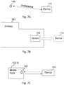
- Fig. 7A shows a block diagram over a situation wherein a power tool 100 is at a certain distance from a geographical point 840.
- the tool control node 110 may be arranged to determine whether the position of the power tool 100 is within a predefined distance D from the geographical point 840, or if the power tool 100 is outside the predetermined distance.
- the tool control node 110 determines the position by comparing the position of the power tool 100 with a set geographical point 840 and calculates the distance between them.
- the geographical point 840 is defined by the location of a presence node 110.
- the position of the presence node 110 may be dynamic.
- the power tool 100 and the tool control node 110 described above may be implemented, by means of program modules of a respective computer program comprising code means which, when run by processor "P" 250 causes the power tool 100 and the tool control node 110 to perform the above-described actions.
- the processor P 250 may comprise a single Central Processing Unit (CPU), or could comprise two or more processing units.
- the processor P 250 may include general purpose microprocessors, instruction set processors and/or related chips sets and/or special purpose microprocessors such as Application Specific Integrated Circuits (ASICs).
- ASICs Application Specific Integrated Circuits
- the processor P 250 may also comprise a storage for caching purposes.
- Each computer program may be carried by computer program products "M" 260 in the power tool 100 and the tool control node 110, shown in Fig. 1 , 2 , 4 , 5 , et al, in the form of memories having a computer readable medium and being connected to the processor P.
- Each computer program product M 260 or memory thus comprises a computer readable medium on which the computer program is stored e.g. in the form of computer program modules "m".
- the memories M 260 may be a flash memory, a Random-Access Memory (RAM), a Read-Only Memory (ROM) or an Electrically Erasable Programmable ROM (EEPROM), and the program modules m could in alternative embodiments be distributed on different computer program products in the form of memories within the power tool 100 and the tool control node 110.
- RAM Random-Access Memory
- ROM Read-Only Memory
- EEPROM Electrically Erasable Programmable ROM
- the technology could be used for authorization in relation to other purposes than theft prevention.
- Some power tools requires special skills from the operator and should therefore not be handled by any user, one example is a woodwork-class for educational purpose where some machines in the class room might be locked to a presence node 110 possessed by the teacher, hence preventing students from using machinery while the teacher is not in the vicinity.
- Another example is for use in DIY (do it yourself) tools for home users where the technology could be adapted as, for example, a child look, allowing parents to store the power tools in areas were children potentially could locate them.
- the most basic of the location determination techniques is to identify the location based on the presence node 120 that is closest to the power tool 100. This may be done by looking at the association between the power tool 100 and the presence node 120 or by measuring signal strength.
- the distance may be calculated based on signal strength or timing information.
- Received Signal Strength Indication is a measurement on how strongly a transmitted signal is being received at a particular distance from the transmitter. The signal strength varies with distance, obstacles and interfering radio frequency signals. Multi path fading also affect the signal strength. In Wi-Fi networks, the signal strength is defined as Received Signal Strength Indication (RSSI). RSSI may be measured by the presence node 120 Link Quality Indicator (LQI) is a metric of the current quality of the received signal. The LQI may provide an estimate of how easily a received signal may be demodulated by accumulating the magnitude of the error between ideal constellations and the received signal over the 64 symbols immediately following the sync word.
- LQI Link Quality Indicator
- Time Difference of Arrival (TDoA, also time of flight) - Distance may be calculated based on signal propagation time. Radio waves travel at a known speed through the wireless medium. Thus, if the time of transmission and time of signal arrival are known, the distance may be computed. Time Difference of Arrival (TDoA) is an example of such a technique. In TDoA, the position may be computed based on the difference in time when the signal arrives at different presence nodes 120.
- Angle may be used to calculate the position.
- the wireless signal arrives at a certain angle.
- the estimated location may be computed.
- Triangulation and Trilateration When the location is estimated based on angle measurements from three or more presence nodes 120 the method is referred to as triangulation.
- the signal strength or timing information from several access points may also be used together to form coverage circles and intersection points. If the distance from at least three different presence nodes 120 may be calculated, this technique is known as trilateration.
- the power tool 100 With the use of algorithms, the power tool 100 most likely position may be pointed based on the information from the different presence nodes 120. The more presence nodes 120 that contribute in computing the location, the more likely it is to get an accurate approximation.
- This location patterning technique may need calibration, in order to record how the wireless signals propagate throughout the environment. During this calibration phase, RF characteristics and real world data regarding how obstacles affect the propagation may be collected and pre-stored in a database. This information may then be compared with real-time information from the presence nodes 120 to achieve a more accurate position approximation.
- MREL Multiple Range Estimation Locator
- LMUs Andrews Location Measurement Units
- MREL may use the transmission time and the time of arrival of the signal to determine a circular range ring, where the power tool 100 may be located. The location may then estimated by the best intersection of the multiple range-rings.
- TDoA calculates the difference in the time of arrival of the mobile signal between multiple pairs of receivers. The differences in arrival time determine hyperbolic curves between receivers of where the power tool 100 may be. The location may then be estimated by the best intersection of the multiple hyperbolic curves.
- distance or position may be determined by usage of at least one of: association or signal strength, timing information, Received Signal Strength Indication (RSSI), Link Quality Indicator (LQI), Time Difference of Arrival/Time-of-Arrival (TDoA/TOA), Angle (AoA), Triangulation and/or Trilateration, Location Patterning, Multiple Range Estimation Locator MREL (Multiple Range Estimation Location), in combination with anyone else of the mentioned solutions.
- RSSI Received Signal Strength Indication
- LQI Link Quality Indicator
- ToA/TOA Time Difference of Arrival/Time-of-Arrival
- Angle Angle
- Triangulation and/or Trilateration Trilateration
- Location Patterning Location Patterning
- Multiple Range Estimation Locator MREL Multiple Range Estimation Location
- Fig. 9 illustrates an embodiment of the solution.
- a presence node 120 may be relocated to different positions. The different positions may be represented in a coordinate system. An example is where the start point of the presence node 120 is determined as coordinate "0". When the presence node 120 is relocated and at each point where a signal is received from the power tool 100, the new coordinate is determined. There by it may be possible to by usage of one presence node 120 simulate a plurality of presence nodes 120, where the simulated plurality of presence nodes 120 may better determine a position of a power tool 100, than a single presence node 120.
- a presence node 120 may determine its coordinate by use of GPS, etc.
- the presence node 120 may also determine a relative coordinate by usage of for example one of gyro, magnetic compass, accelerometer, tilt sensor, gyroscope, altimeter, not limiting to other type of sensors for measuring movements and/or relative positions.
- the coordinate system may be a three dimensional coordinate system, such when a presence node 120 is relocated and during the relocation determines three dimensional coordinates for each signal received from the power tool 100.
- a user of a presence node 120 may by moving around, simulate a group of users where each user has a presence node 120, thereby it may be possible to better determine a position of a power tool 100 than with a single presence node 120 stationary at one point.
- the time difference of arrival is measured by the power tool 100, instead of the presence node 120.
- An illustrative example is where at least one presence node 120 transmits a signal, such an alert signal or any other signal, such that the power tool 100 may measure the time of flight from the presence node 120 to the power tool 100.
- the power tool 100 may transmit the response to the alert signal, or any other signal, the response including the identification of the power tool 100 and also the measured transmission time between the presence node 120 and the power tool 100.
- the power tool 100 may additionally, based on the measured transmission time between the presence node 120 and the power tool 100, determine the distance between the presence node 120 and the power tool 100.
- the response transmitted by the power tool 100 may then include: identification of the power tool 100, measured transmission time between the presence node 120 and the power tool 100, and the determined distance between the presence node 120 and the power tool 100.
- the time may be measured with an accuracy down to microseconds. In another embodiment, the time may be measured with an accuracy down to nanoseconds.
- the power tool 100 may be measuring the time of arrival, time difference of arrival or time of flight, instead of the presence node 120.
- An advantage may be that the power tool 100 may be easier to adopt for measuring the signals time of flight, than adopting the presence node 120 for measuring the time.
- Another advantage may be that the power tool 100 may be adapted to measure time with a better accuracy.
- Another advantage may be that by performing measurement in the device, more presence nodes 120 may participate in positioning a power tool 100 with a better accuracy then only presence node 120 with support for measuring the time.
- Another advantage with measuring time in the power tool 100 is that a plurality of additional sources for determination of the distance between a mobile terminal and a power tool 100 may enable avoidance of signal reflections and other disturbances.
- the power tool 100 may transmit a response to each presence node 120, from which the power tool 100 has received a valid identification.
- the response may include any of: the identification, measured transmission time, and determined distance.
- the plurality of presence nodes 120 may better determine the position of the power tool 100.
- the presence nodes can further be utilized for positioning of tools through Time of Arrival.
- positioning is not limited to pear-to-pear networks and can thereby be any form of network communication, comprising other network communication units such as for example access points.
- a method wherein a first node for determining the distance between two nodes in a communication network utilizes the media access control layer (MAC-layer) present in multiple standards, such as the IEEE 802.11x standard.
- MAC-layer media access control layer
- the MAC-layer is adapted to communicate the information of high level layers as one of its tasks but some frames can be transmitted standalone by the MAC-layer. By utilizing those frames, and/or, modifying behavior of a MAC-layer in a wireless communication network by adding additional features, processing times can be changed from an unreliable and changeable time factor to an approximated constant.
- the possibility to approximate the processing time makes it possible to subtract the processing time and utilize Time of Arrival / Time of Flight measurements.
- the methods described below thereby provide an enhanced system for determining the distance between two nodes in a communication network by significantly reduce the problem of previous methods.
- the first presence node comprises a network communication unit with a medium access control layer (MAC-Layer), and the first presence node performs a method comprising the steps:
- Positioning could also be accomplished through nodes in a wireless communication network, comprising a network communication unit with a medium access control layer (MAC-Layer), said node configured to calculate the Time of Arrival and/or Time of Flight based on a counted time from transmission of a response request message in the medium access control layer of said node to the corresponding arrival of a response to said response request message in the medium access control layer (MAC-Layer) of said node.
- MAC-Layer medium access control layer
- the counter can in one embodiment count processor cycles based on for example a central processing unit clock frequency. It is further understood that the counter can be any means arranged in a node, or attached hardware or software, which can directly or indirectly be used to determine a passed time.
- an additional clock may be added to at least one node in a wireless communication network that uses a higher clock frequency than the standard clock.
- the 1 MHz clock frequency may be complemented with an additional clock that provides better resolution for distance determination.
- the complementary clock arranged with a frequency at 30-50 MHz, 50-500 MHz, 100 MHz or higher, or approximately 40 MHz.
- RTS and CTS messages are handled in the MAC-layer of a network communication unit structure and thereby have the advantage of relatively stable processing times. This applies not only between different version of the same node but also between different sorts of nodes, such as mobile phones, access points, Wi-Fi-tags, etc. Furthermore, RTS and CTS messages are part of some wireless network communication standards and are thereby always present in devices following those standards.
- wireless communication networks such as for IEEE 802.11x, Bluetooth, ZigBee, or any other wireless communication network can be used.
- a first presence node transmits a Request-to-Send message (RTS) and a second presence node response with a Clear-to-Send message (CTS) before any data is transferred.
- RTS Request-to-Send message
- CTS Clear-to-Send message
- the RTS and CTS messages may be handled in the MAC-Layers of both the first presence node and the second presence node and may be thereby not affected of processing times in the CPUs of the nodes.
- the Time of Arrival / Time of Flight can thereby be calculated and used for distance determination and positioning.
- frequencies could be used. For example could frequencies from 400 MHz up to 5,5 GHz preferably be used in different embodiments of the invention.
Landscapes
- Engineering & Computer Science (AREA)
- Physics & Mathematics (AREA)
- General Physics & Mathematics (AREA)
- Computer Networks & Wireless Communication (AREA)
- Mechanical Engineering (AREA)
- Human Computer Interaction (AREA)
- Manufacturing & Machinery (AREA)
- Automation & Control Theory (AREA)
- Lock And Its Accessories (AREA)
- Portable Power Tools In General (AREA)
- Position Fixing By Use Of Radio Waves (AREA)
- Mobile Radio Communication Systems (AREA)
Description
- The present disclosure relates to a method in a first presence node adapted for determining the distance between said first presence node and a second presence node in a wireless communication network, this method being used in a method for enabling unlocking and locking of a tool.
- Entrepreneurs and construction companies are using various machines and tools on construction sites. This ranges from the self-employed carpenter performing a renovation of a cottage all the way to the large construction company building entire new hospitals, districts, highways, bridges and other major projects. The workers doing the construction uses all kind of tools from pencils and knifes all the way to excavators and cranes. When it comes to power tools, also frequently used by the construction workers, they may involve a significant value in combination with a compact format. Such tools may include electric driven tools, fuel/gasoline driven tools, pneumatic driven tools, hydraulic driven tools, not limiting to similar powered tools. Examples of power tools are: screwdrivers, bolt gun, nail gun, impact drill, angle grinder, cutter, saw, reciprocating saw, not limiting to other types of tools. Obviously a crane may represent a large capital value, but it is rather unpractical for the simple thief or the regular criminal organization to steal a crane. However, the power tool is easy to carry away and may represent a significant value on a market, or may be used for other criminal activities. This is a vast problem for construction companies, which power tools is being stolen or just disappears from construction sites. The lost tools costs money to replace drives insurance costs, and delays planned work.
- Another problem is where owner of tools, for example tool rental companies, is to get rental returns of tools in time or according to an agreement. Another problem, of a rather practical character, which yet may be troublesome, may be on a large construction site, to find tools being spread out over a large area or space. A method for reducing communications in a peer-to-peer wireless network having nodes is disclosed in
US 2004/0246903 A1 . - It is an object of the invention to address at least some of the problems and issues outlined above. It is possible to achieve these objects and others by using a method as defined in the attached claims.
- According to one example, a method is provided in a power tool for enabling unlocking and locking of the power tool for prevention of unauthorized use, the method comprising: receiving an unlock message to a control unit, the message including an instruction to unlock the tool, unlocking the power tool according to the instruction by the control unit via an actuator unit, counting an authorization time period from reception of the first message to the control unit by a counter, wherein when the counted authorization time period exceed a predetermined threshold, locking the power tool by the control unit via the actuator unit, thereby enabling prevention of unauthorized use of the power tool by remote unlocking and locking.
- According to another example, a method is provided in a tool control node for enabling unlocking and locking of a tool for prevention of unauthorized use, the method comprising transmitting an unlock message to the tool, the message including an instruction to unlock the tool, counting an authorization time period from transmission of the unlock message to the tool, wherein when the counted authorization time period exceed a predetermined threshold, transmitting of a lock message including an instruction to lock the tool, thereby enabling prevention of unauthorized use of the tool by remote unlocking and locking.
- According to another example, a power tool is provided adopted to enable unlocking and locking of the power tool for prevention of unauthorized use, the power tool adopted to receive an unlock message to a control unit, the message including an instruction to unlock the tool, unlock the power tool according to the instruction by the control unit via an actuator unit, count an authorization time period from reception of the first message to the control unit by a counter, wherein when the counted authorization time period exceed a predetermined threshold, lock the power tool by the control unit via the actuator unit, thereby enabling prevention of unauthorized use of the power tool by remote unlocking and locking.
- In one possible example, the actuator unit is at least one of electrical switch, mechanical lock and semiconductor based switch. In another possible example, when a second unlock message is received before the predetermined threshold is reached, the counter is restarted, such that the power tool remains unlocked. In another possible example, the unlock message includes a first key, wherein, the first key is required by the control unit for authorization of the message. In another possible example, the drive unit requires at least one of the first key or a second key from the control unit, for enabling of the drive unit. In another possible example, a lock message is received by the control unit, the lock message including an instruction to lock the tool, wherein the tool is locked by the control unit via the actuator unit. In another possible example, a position message including an alert signal is received by the control unit, the position message including an instruction to repeatedly transmit a response signal as a response to the alert signal, thereby enabling positioning of the tool. In another possible example, the communication with the tool is encrypted. In another possible example, the tool has a physical tamper protection.
- In another example, the positioning of the tool is instead made by the tool control unit. This could for example be done through means of a message including an alert signal is received by the control unit. The message triggers the control unit to transmit a signal requesting response signals from presence nodes nearby followed by receiving response signals to the control unit from presence nodes nearby and thereby enabling positioning of the tool. This allows for the positing to in one embodiment be made within the tool enabling for the tool to send a response comprising a position to for example the tool control node.
- In another example, a power tool control unit adopted to enable unlocking and locking of a tool for prevention of unauthorized use is adopted to:
- transmit an unlock message to the tool, the message including an instruction to unlock the tool,
- determine the position of the tool and check if said tool is within a predetermined area,
- if the tool leave said predetermined area transmit a lock message including an instruction to lock the tool, thereby enabling prevention of unauthorized use of the tool.
- The power tool control unit can further be configured to sound and transmit an alarm if said tool leaves the predetermined area.
- Further possible features and benefits of this solution will become apparent from the detailed description below.
- The solution will now be described in more detail by means of exemplary embodiments and with reference to the accompanying drawings, in which:
-
Fig. 1 is a block diagram illustrating the solution. -
Fig 2 is a block diagram illustrating a power tool. -
Fig. 3 is a flow chart illustrating a procedure in a power tool, according to possible embodiments. -
Fig 4 . is a signaling diagram illustrating an example of a delegation when the solution is used, according to further possible embodiments. -
Fig. 5 is a communication scenario illustrating the solution, according to further possible embodiments. -
Fig. 6 is a flow chart illustrating a procedure in a tool control node, according to possible embodiments. -
Fig. 7A-C are illustrations of positioning scenarios for a power tool. -
Fig. 8 illustrates examples of computer implementations. -
Fig. 9 shows an illustration of relocation of a presence node. - Briefly described, a solution is provided to avoid theft of power tools and other capital intensive machineries related to construction sites. By having a lock on a power tool, which default is locked, it may be less attractive for theft. A lock which is remotely controlled. Only when a user is authorized by the owner of the tool, the tool is unlocked. The tool may be unlocked for a specific period of time. The tool may further be unlocked within a specific geographical or a specific volume. An unlock message may be transmitted from a tool control node, which instructs the power tool to be unlocked. The power tool is then unlocked and fully usable for a certain time period, before the time period has passed, a new unlock message must be received by the power tool, otherwise it will be locked for further usage. So if the tool does not receive any unlock message or, if the tool is outside a specified area, it will automatically be locked and unusable. An owner of a tool may for some reason want to revoke an authorization from a user to use the tool, for example if an invoice is not paid for. Than may the tool owner transmit a lock message to the tool, such it becomes unusable. The tool owner may delegate a right to transmit unlock and lock messages to an intermediate, a presence node. An example may be the tool rental company delegating to a site manager. Such right may also be revoked.
- Now the solution will be described in more detail.
Fig. 1 shows a block diagram with apower tool 100, atool control node 110 for controllingpower tools 100 and apresence node 120 for handling of delegated controlling ofpower tools 100. -
Fig. 2 shows a block diagram of thetool 100. The tool includes acontrol unit 210 for controlling unlocking and locking of thepower tool 100 and other actions. Thepower tool 100 further includes acounter 240 for counting of time. Thepower tool 100 further includes anactuator unit 250 for unlocking and locking of thepower tool 100. The power tool may also include anenergy supply unit 220, adrive unit 230 and acommunication unit 260 for reception and transmission of messages. - Power tool may also be denoted "device", appliances, powered machine, not limiting to other similar suitable terms. Appliances may include washer, dryer, dishwasher, heat pump, stove, oven, microwave, not limiting to other appliances used in a home or office. Tool control node may also be denoted "remote node" not limiting to other similar suitable terms. Presence node may also be denoted "mobile node" not limiting to other similar suitable terms. A few examples of the
tool control node 110 may be, a server in a communications network, a virtual server in a communications network, a mobile phone or an application installed on a mobile phone, a PDA (Personal Digital assistant) or an application installed on a PDA, not limiting to other similar nodes. A few examples of apresence node 120 may be a mobile phone or an application installed on a mobile phone, a PDA (Personal Digital assistant) or an application installed on a PDA, a gateway, access switch, access router, WLAN access point (Wireless Local Area Network) not limiting to other similar nodes. The term "unlock" may also be denoted "enable", and the term "lock" may also be denoted "disabled". -
Fig. 3 shows a method in apower tool 100 for enabling unlocking and locking of the power tool for prevention of unauthorized use. The method comprises receiving S100 an unlock message to acontrol unit 210, the message including an instruction to unlock thetool 100. The method further comprises unlocking S110 thepower tool 100 according to the instruction by thecontrol unit 210 via anactuator unit 250. The method further comprises counting S120 an authorization time period from reception of the first message to thecontrol unit 210 by acounter 230, wherein when the counted authorization time period exceed a predetermined threshold, thepower tool 100 is locked S130 by the control unit (210) via the actuator unit (250), thereby enabling prevention of unauthorized use of the power tool (100) by remote unlocking and locking. - The unlock message may come from a
tool control node 110. The message may be carried via wireless radio communication, for example such as WiFi according to IEEE 802.11 (Institute of Electrical and Electronics Engineers), RFID (Radio-frequency identification), Bluetooth, not limiting to other similar communication methods. Protocols used for carrying the message may be Ethernet, TCP/UDP/IP (Transmission Control Protocol/User Datagram Protocol/Internet Protocol). Further examples of protocols which may be used are; SMTP (Simple Mail Transfer Protocol), SMS/MMS (Short Message Service / Multimedia Messaging Service), HTTP/HTTPS (Hypertext Transfer Protocol/Secure), SIP/SIPS (Session Initiation Protocol/Secure), not limiting to other suitable protocols for messages or communication with apower tool 100. The message with the unlock instruction may also include other information, such as a time stamp, or the length of the authorization time period, not limiting to other information. The authorization time period may be a time period during which thepower tool 100 may be unlocked and prepared for normal operation. During the authorization time period, thepower tool 100 may be outside radio contact with for example thetool control node 110. Thecounter 230 counts the authorization time period, such when the authorization time period exceeds the predetermined threshold thepower tool 100 is locked. When thepower tool 100 is locked it may not be possible to use for normal operation. The threshold may be adjusted, for example by manually setting a different value, or by reception of a different value via the unlock message or the lock message. - In an example of the solution, the
actuator unit 250 may be at least one of electrical switch, mechanical lock and semiconductor based switch. Depending of the propulsion of thepower tool 100 different kinds of locks may be more or less suitable. A combination of an electrical switch, mechanical lock and semiconductor based switch may be used for locking thepower tool 100. In an example of the solution, when a second unlock message is received before the predetermined threshold is reached, thecounter 230 may be restarted, such that thepower tool 100 remains unlocked. By this action, thepower tool 100 may be used in normal operation without interruption. Unless thecounter 230 is restarted by for example a second unlock message, thepower tool 100 may be locked from normal operation. In an example of the solution, the unlock message may include a first key, wherein the first key may be required by thecontrol unit 210 for authorization of the unlock message. By usage of the first key, it may be possible to authorize the unlock message or any other messages received by thetool 100. Thereby may thepower tool 100 be enabled to protect itself from receiving or taking any actions based on unauthorized messages. - In an example of the solution, the
drive unit 230 may require at least one of the first key or a second key from thecontrol unit 110, for enabling of thedrive unit 230. If the power tool for example has been stolen, and the control unit is replaced with a modified control unit, the power tool may then be prevented from unauthorized usage, because the drive unit may expect a correct key before propulsion of thepower tool 100. In an example of the solution, a lock message may be received by thecontrol unit 210, where the lock message may include an instruction to lock thetool 100, wherein thetool 100 may be locked by thecontrol unit 210 via theactuator unit 250. - In an example of the solution, a position message including an alert signal is received by the control unit (210), the position message including an instruction to repeatedly transmit a response signal as a response to the alert signal, thereby enabling positioning of the tool (100). When a
power tool 100 is missing, because it has been lost/misplaced or stolen, it may then be possible to position the tool. By thepower tool 100 transmitting the response signal, it may then be possible to determine a distance to thepower tool 100. It may also be possible to determine a direction to thepower tool 100. It may also be possible to determine a position of thepower tool 100. In an example of the solution showed inFig. 4 , thepower tool 100 may be arranged to receive an alert signal from thecontrol node 110. The alert signal may include an identification of thepower tool 100, alerting thepower tool 100 by matching the received identification with a preprogrammed identification of thepower tool 100, transmitting a response signal to the alert signal, including the identification of thepower tool 100 matching the received identification, thereby enabling determination of the position of thepower tool 100. In an example, thepower tool 100 is adapted to repeatedly transmit the response to the alert signal. Hereby, a risk that for instance acontrol node 110 does not receive the response due to poor signal strength/connectivity resulting e.g. from the position of thepower tool 100 or thepresence node 120 may be reduced. Another advantage may be, if thepower tool 100 changes locations, it may be possible to determine the new position. -
Fig. 5 , shows an overview of the solution from a positioning perspective, comprising a plurality ofpresence nodes 120. The solution may further comprise atool control node 110 comprising for instance apresence node 120. Thecontrol node 110 is arranged to transmit a positioning request message, including an identification of thepower tool 100, to a plurality ofpresence nodes 110. Such plurality of presence nodes may be a closed user group of users which have agreed to use a specific service, a random group ofpresence nodes 120 located in the vicinity of thecontrol node 110, an open user community which users may subscribe to, an ad hoc network, or a meshed network, or similar. Thecontrol node 110 is further arranged to receive at least one response to the positioning request message, including a calculated distance to thepower tool 100 from thepresence node 120, and a position of thepresence node 120 as well as determining a position of thepower tool 100 by calculation of the distance of thepower tool 100 from thepresence node 120 in combination with the position of the at least onepresence node 100. In an example of the solution, thecontrol node 110 may be arranged to calculate the position of thepower tool 100 using any of triangulation, multilateration or trilateration upon receiving responses to the position request message from a plurality ofpresence nodes 120. According to an embodiment, thecontrol node 110 is hosted by apresence node 120, i.e. thecontrol node 110 may itself be used to the determined the position of thepower tool 100. - In an example of the solution, the communication with the
power tool 100 may be encrypted. By encryption of the communication betweenpower tool 100 and other nodes, unauthorized access to thepower tool 100 may be prevented, as well as man-in-the-middle types of attacks. In an example of the solution, thetool 100 may have a physical tamper protection. A physical tamer protection may prevent or reduce the risk of unauthorized physical access to thepower tool 100. The physical tamer protection may also prevent or reduce the risk of unauthorized physical access to key components of thepower tool 100. -
Fig. 6 shows a flowchart of a method in atool control node 110 for enabling unlocking and locking of a tool for prevention of unauthorized use. The method comprises transmitting an unlock message to thetool 100, where the message includes an instruction to unlock thetool 100. The method further includes counting an authorization time period from transmission of the unlock message to thetool 100, wherein when the counted authorization time period exceed a predetermined threshold, the method further comprises transmitting of a lock message including an instruction to lock the tool (100), thereby enabling prevention of unauthorized use of thetool 100 by remote unlocking and locking. - In an example of the solution, when a use time period end may be beyond the authorization time period end, a second unlock message may be transmitted to the
tool 100 before the predetermined authorization time period threshold is reached, such that thepower tool 100 remains unlocked. The authorization time period may for example be 24 hours, i.e. apower tool 100 may be used for up to 24 hours, and at the end of the 24 hours thepower tool 100 may be locked from normal operation, unless a second unlock message may be transmitted from thetool control node 110 to thepower tool 100. The authorization period may be in a range from seconds up to days or weeks, depending on practical implementation. - The use time period may be a time period of an intended use period on a construction site, for example a month. The use period may be in a range from single hours up to months or even years. A use time period may be possible to interrupt, or change to a shorter or longer period. An example is where a customer of a rented
power tool 100, may want to extend the rental period, or when a customer not has paid invoices, then the use time period may be extended, or interrupted. In the invoicing case, an unlock message may be transmitted from thetool control node 110 to thepower tool 100, when the invoice is paid, such that the rental customer then may continue to use thepower tool 100 under normal operation. - In an example of the solution, for example illustrated in
Fig. 4 , a position message including an alert signal may be transmitted to thepower tool 100, thereby enabling positioning of the tool (100). - In an example of the solution, a delegated authorization to transmit unlock and lock messages to a specified power tool (100) message including the instruction to unlock the tool (100) may be transmitted to a presence node (120).
Fig. 5 shows thetool control node 110, which may transmit the delegation to one of or all of the presence nodes 120:1, 120:B, 120:C.Fig. 5 also illustrated how the presence nodes 120:1, 120:B, 120:C may cooperate for positioning of amissing power tool 100. In an example of the solution, an annulation of the delegated authorization may be transmitted to the presence node (120). - The
power tool 100, for example illustrated inFig. 2 , is adopted to enable unlocking and locking of thepower tool 100 for prevention of unauthorized use. Thepower tool 100 is adopted to receive an unlock message to thecontrol unit 210, where the message includes an instruction to unlock thetool 100. Thepower tool 100 is further adopted to unlock thepower tool 100 according to the instruction by thecontrol unit 210 via theactuator unit 250. Thepower tool 100 is further adopted to count an authorization time period from reception of the first message to thecontrol unit 210 by thecounter 230, wherein when the counted authorization time period exceed a predetermined threshold, thepower tool 100 is locked by thecontrol unit 210 via theactuator unit 250, thereby enabling prevention of unauthorized use of thepower tool 100 by remote unlocking and locking. -
Fig. 1 andFig. 5 et. al. shows thetool control node 110 adopted to enable unlocking and locking of a tool for prevention of unauthorized use. Thetool control node 110 is adopted to transmit the unlock message to thetool 100, the message including an instruction to unlock thetool 100. Thetool control node 110 is further adopted count the authorization time period from transmission of the unlock message to thetool 100, wherein when the counted authorization time period exceed a predetermined threshold,tool control node 110 is adopted to transmit the lock message including an instruction to lock thetool 100, thereby enabling prevention of unauthorized use of thetool 100 by remote unlocking and locking. -
Fig. 7A shows a block diagram over a situation wherein apower tool 100 is at a certain distance from a geographical point 840. Thetool control node 110 may be arranged to determine whether the position of thepower tool 100 is within a predefined distance D from the geographical point 840, or if thepower tool 100 is outside the predetermined distance. According to one embodiment shown in 7B, thetool control node 110 determines the position by comparing the position of thepower tool 100 with a set geographical point 840 and calculates the distance between them. According to another embodiment as is further disclosed inFig. 7C , the geographical point 840 is defined by the location of apresence node 110. The position of thepresence node 110 may be dynamic. - Now looking at
Fig. 8 . Thepower tool 100 and thetool control node 110 described above may be implemented, by means of program modules of a respective computer program comprising code means which, when run by processor "P" 250 causes thepower tool 100 and thetool control node 110 to perform the above-described actions. Theprocessor P 250 may comprise a single Central Processing Unit (CPU), or could comprise two or more processing units. For example, theprocessor P 250 may include general purpose microprocessors, instruction set processors and/or related chips sets and/or special purpose microprocessors such as Application Specific Integrated Circuits (ASICs). Theprocessor P 250 may also comprise a storage for caching purposes. - Each computer program may be carried by computer program products "M" 260 in the
power tool 100 and thetool control node 110, shown inFig. 1 ,2 ,4 ,5 , et al, in the form of memories having a computer readable medium and being connected to the processor P. Each computerprogram product M 260 or memory thus comprises a computer readable medium on which the computer program is stored e.g. in the form of computer program modules "m". For example, the memories M 260 may be a flash memory, a Random-Access Memory (RAM), a Read-Only Memory (ROM) or an Electrically Erasable Programmable ROM (EEPROM), and the program modules m could in alternative embodiments be distributed on different computer program products in the form of memories within thepower tool 100 and thetool control node 110. - In an example embodiment of the solution the technology could be used for authorization in relation to other purposes than theft prevention. Some power tools requires special skills from the operator and should therefore not be handled by any user, one example is a woodwork-class for educational purpose where some machines in the class room might be locked to a
presence node 110 possessed by the teacher, hence preventing students from using machinery while the teacher is not in the vicinity. Another example is for use in DIY (do it yourself) tools for home users where the technology could be adapted as, for example, a child look, allowing parents to store the power tools in areas were children potentially could locate them. - In the following a few examples of positioning techniques is described. The examples are for illustration of how a
power tool 100 may be determined in direction, distance, and/or position. These examples are not limiting other techniques to be used. -
Closest presence node 120. The most basic of the location determination techniques, is to identify the location based on thepresence node 120 that is closest to thepower tool 100. This may be done by looking at the association between thepower tool 100 and thepresence node 120 or by measuring signal strength. - Calculation of the approximately distance between the
power tool 100 and one ormore presence nodes 120. This technique is called lateration. The distance may be calculated based on signal strength or timing information. - Received Signal Strength Indication (RSSI) - Signal strength is a measurement on how strongly a transmitted signal is being received at a particular distance from the transmitter. The signal strength varies with distance, obstacles and interfering radio frequency signals. Multi path fading also affect the signal strength. In Wi-Fi networks, the signal strength is defined as Received Signal Strength Indication (RSSI). RSSI may be measured by the
presence node 120 Link Quality Indicator (LQI) is a metric of the current quality of the received signal. The LQI may provide an estimate of how easily a received signal may be demodulated by accumulating the magnitude of the error between ideal constellations and the received signal over the 64 symbols immediately following the sync word. - Time Difference of Arrival (TDoA, also time of flight) - Distance may be calculated based on signal propagation time. Radio waves travel at a known speed through the wireless medium. Thus, if the time of transmission and time of signal arrival are known, the distance may be computed. Time Difference of Arrival (TDoA) is an example of such a technique. In TDoA, the position may be computed based on the difference in time when the signal arrives at
different presence nodes 120. - Angle (AoA) - Instead of timing information, angles may be used to calculate the position. At each access point, the wireless signal arrives at a certain angle. By using geometric relationships between the angles of arrival at two
presence nodes 120, the estimated location may be computed. - Triangulation and Trilateration, - When the location is estimated based on angle measurements from three or
more presence nodes 120 the method is referred to as triangulation. The signal strength or timing information from several access points may also be used together to form coverage circles and intersection points. If the distance from at least threedifferent presence nodes 120 may be calculated, this technique is known as trilateration. With the use of algorithms, thepower tool 100 most likely position may be pointed based on the information from thedifferent presence nodes 120. Themore presence nodes 120 that contribute in computing the location, the more likely it is to get an accurate approximation. - Location Patterning - None of the above position determination techniques take into account signal propagation characteristics, such as reflection, attenuation and multi-path fading. However, with the location patterning technique, such characteristics of the actual wireless medium considered in the position computation. This location patterning technique may need calibration, in order to record how the wireless signals propagate throughout the environment. During this calibration phase, RF characteristics and real world data regarding how obstacles affect the propagation may be collected and pre-stored in a database. This information may then be compared with real-time information from the
presence nodes 120 to achieve a more accurate position approximation. - Multiple Range Estimation Locator MREL (Multiple Range Estimation Location) used with Andrews Location Measurement Units (LMUs). MREL may use the transmission time and the time of arrival of the signal to determine a circular range ring, where the
power tool 100 may be located. The location may then estimated by the best intersection of the multiple range-rings. Conversely, TDoA calculates the difference in the time of arrival of the mobile signal between multiple pairs of receivers. The differences in arrival time determine hyperbolic curves between receivers of where thepower tool 100 may be. The location may then be estimated by the best intersection of the multiple hyperbolic curves. - In an embodiment, distance or position may be determined by usage of at least one of: association or signal strength, timing information, Received Signal Strength Indication (RSSI), Link Quality Indicator (LQI), Time Difference of Arrival/Time-of-Arrival (TDoA/TOA), Angle (AoA), Triangulation and/or Trilateration, Location Patterning, Multiple Range Estimation Locator MREL (Multiple Range Estimation Location), in combination with anyone else of the mentioned solutions.
-
Fig. 9 illustrates an embodiment of the solution. Apresence node 120 may be relocated to different positions. The different positions may be represented in a coordinate system. An example is where the start point of thepresence node 120 is determined as coordinate "0". When thepresence node 120 is relocated and at each point where a signal is received from thepower tool 100, the new coordinate is determined. There by it may be possible to by usage of onepresence node 120 simulate a plurality ofpresence nodes 120, where the simulated plurality ofpresence nodes 120 may better determine a position of apower tool 100, than asingle presence node 120. Apresence node 120 may determine its coordinate by use of GPS, etc. Thepresence node 120 may also determine a relative coordinate by usage of for example one of gyro, magnetic compass, accelerometer, tilt sensor, gyroscope, altimeter, not limiting to other type of sensors for measuring movements and/or relative positions. - In an embodiment, not shown in
Fig. 9 , the coordinate system may be a three dimensional coordinate system, such when apresence node 120 is relocated and during the relocation determines three dimensional coordinates for each signal received from thepower tool 100. - A user of a
presence node 120 may by moving around, simulate a group of users where each user has apresence node 120, thereby it may be possible to better determine a position of apower tool 100 than with asingle presence node 120 stationary at one point. - In an embodiment, the time difference of arrival is measured by the
power tool 100, instead of thepresence node 120. An illustrative example is where at least onepresence node 120 transmits a signal, such an alert signal or any other signal, such that thepower tool 100 may measure the time of flight from thepresence node 120 to thepower tool 100. Thepower tool 100 may transmit the response to the alert signal, or any other signal, the response including the identification of thepower tool 100 and also the measured transmission time between thepresence node 120 and thepower tool 100. Thepower tool 100 may additionally, based on the measured transmission time between thepresence node 120 and thepower tool 100, determine the distance between thepresence node 120 and thepower tool 100. The response transmitted by thepower tool 100 may then include: identification of thepower tool 100, measured transmission time between thepresence node 120 and thepower tool 100, and the determined distance between thepresence node 120 and thepower tool 100. In an embodiment, the time may be measured with an accuracy down to microseconds. In another embodiment, the time may be measured with an accuracy down to nanoseconds. - There may be advantages with the
power tool 100 measuring the time of arrival, time difference of arrival or time of flight, instead of thepresence node 120. An advantage may be that thepower tool 100 may be easier to adopt for measuring the signals time of flight, than adopting thepresence node 120 for measuring the time. Another advantage may be that thepower tool 100 may be adapted to measure time with a better accuracy. Another advantage may be that by performing measurement in the device,more presence nodes 120 may participate in positioning apower tool 100 with a better accuracy then onlypresence node 120 with support for measuring the time. Another advantage with measuring time in thepower tool 100 is that a plurality of additional sources for determination of the distance between a mobile terminal and apower tool 100 may enable avoidance of signal reflections and other disturbances. - In a situation where there is a plurality of
presence nodes 120, thepower tool 100 may transmit a response to eachpresence node 120, from which thepower tool 100 has received a valid identification. The response may include any of: the identification, measured transmission time, and determined distance. The plurality ofpresence nodes 120 may better determine the position of thepower tool 100. - The presence nodes can further be utilized for positioning of tools through Time of Arrival. Such positioning is not limited to pear-to-pear networks and can thereby be any form of network communication, comprising other network communication units such as for example access points.
- According to one aspect of the present solution, a method is provided wherein a first node for determining the distance between two nodes in a communication network utilizes the media access control layer (MAC-layer) present in multiple standards, such as the IEEE 802.11x standard.
- It has been shown that network communication conducted within the MAC-layer without the involvement of higher level layers provide processing times that are relatively constant. The MAC-layer is adapted to communicate the information of high level layers as one of its tasks but some frames can be transmitted standalone by the MAC-layer. By utilizing those frames, and/or, modifying behavior of a MAC-layer in a wireless communication network by adding additional features, processing times can be changed from an unreliable and changeable time factor to an approximated constant. The possibility to approximate the processing time makes it possible to subtract the processing time and utilize Time of Arrival / Time of Flight measurements. The methods described below thereby provide an enhanced system for determining the distance between two nodes in a communication network by significantly reduce the problem of previous methods.
- This can be done in an open user community, as previously described, wherein users subscribes to, an ad hoc network, or a meshed network, or similar. Such method can for example be conducted in a first presence node adapted for determining the distance between said first presence node and a second presence node in a wireless communication network. The first presence node comprises a network communication unit with a medium access control layer (MAC-Layer), and the first presence node performs a method comprising the steps:
- transmitting a response request message,
- starting a first counter at transmission of said response request message,
- receiving a response to said response request message,
- stopping the counter at reception of the response to said response request message,
- determining based on the counter result the distance between said first and second presence node,
wherein
said counter result is the period from transmission of said response request message to the arrival of said response in the medium access control layer (MAC-Layer) of said first presence node network communication unit. - Positioning could also be accomplished through nodes in a wireless communication network, comprising a network communication unit with a medium access control layer (MAC-Layer), said node configured to calculate the Time of Arrival and/or Time of Flight based on a counted time from transmission of a response request message in the medium access control layer of said node to the corresponding arrival of a response to said response request message in the medium access control layer (MAC-Layer) of said node.
- The counter can in one embodiment count processor cycles based on for example a central processing unit clock frequency. It is further understood that the counter can be any means arranged in a node, or attached hardware or software, which can directly or indirectly be used to determine a passed time.
- For enablement of positioning determination through Time of Arrival based on MAC-Layer communication, an additional clock may be added to at least one node in a wireless communication network that uses a higher clock frequency than the standard clock. For example, in an IEEE 802.11x wireless communication network system the 1 MHz clock frequency may be complemented with an additional clock that provides better resolution for distance determination. In a preferred embodiment is such a complementary clock arranged with a frequency at 30-50 MHz, 50-500 MHz, 100 MHz or higher, or approximately 40 MHz.
- RTS and CTS messages are handled in the MAC-layer of a network communication unit structure and thereby have the advantage of relatively stable processing times. This applies not only between different version of the same node but also between different sorts of nodes, such as mobile phones, access points, Wi-Fi-tags, etc. Furthermore, RTS and CTS messages are part of some wireless network communication standards and are thereby always present in devices following those standards.
- For the determination of the position, wireless communication networks, such as for IEEE 802.11x, Bluetooth, ZigBee, or any other wireless communication network can be used. For example, a first presence node transmits a Request-to-Send message (RTS) and a second presence node response with a Clear-to-Send message (CTS) before any data is transferred. The RTS and CTS messages may be handled in the MAC-Layers of both the first presence node and the second presence node and may be thereby not affected of processing times in the CPUs of the nodes. The Time of Arrival / Time of Flight can thereby be calculated and used for distance determination and positioning.
- It is further understood that different frequencies could be used. For example could frequencies from 400 MHz up to 5,5 GHz preferably be used in different embodiments of the invention.
- While the solution has been described with reference to specific exemplary embodiments, the description is generally only intended to illustrate the inventive concept and should not be taken as limiting the scope of the solution. For example, the terms "power tool", "appliances", "presence node" and "tool control node" have been used throughout this description, although any other corresponding nodes, functions, and/or parameters could also be used having the features and characteristics described here. The solution is defined by the appended claims.
Claims (8)
- Method in a first presence node (120) adapted for determining the distance between said first presence node and a second presence node in a wireless communication network, wherein said first presence node comprises a network communication unit with a medium access control layer (MAC-Layer), and the first presence node performs a method comprising the steps:- transmitting a response request message,- starting a first counter at transmission of said response request message,- receiving a response to said response request message,- stopping the counter at reception of the response to said response request message,- determining based on the counter result the distance between said first and second presence node,
wherein
said counter result is the period from transmission of said response request message to the arrival of said response in the medium access control layer (MAC-Layer) of said first presence node network communication unit. - Method according to claim 1, wherein the first presence node transmits a Request-to-Send message (RTS) and the second presence node response with a Clear-to-Send message (CTS) before any data is transferred that affects the processing time in the CPUs of the first presence node and the second presence node.
- Method according to claim 2, wherein the RTS and CTS messages are handled in the MAC-Layers of both the first presence node and the second presence node.
- Method according to any one of claims 1-3, wherein Time of Arrival or Time of Flight is calculated and used for distance determination and positioning.
- Method according to any one of claims 1-4, wherein a radio frequency from 400 MHz to 5,5 GHz is used.
- A method in a first presence node (120) for enabling unlocking and locking of a tool for prevention of unauthorized use of the tool, the method comprising:- transmitting a first unlock message to the tool (100), the message including an instruction to unlock the tool (100),- counting an authorization time period from transmission of the unlock message to the tool (100),- when a use time period end is beyond the authorization time period end,- transmitting of a second unlock message to the tool (100) before the predetermined authorization time period threshold is reached, such that the power tool (100) remains unlocked,- transmitting of a position message including an alert signal and a response request message to the power tool (100), thereby enabling positioning of the tool (100) according to the method of any one of claims 1-5,- when the counted authorization time period exceed a predetermined threshold,- transmitting a lock message including an instruction to lock the tool (100), thereby enabling prevention of unauthorized use of the tool (100) by remote unlocking and locking.
- A computer program, comprising computer readable code means, which when run in any one of a power tool (100), a tool control node (110), and a presence node (120) is arranged to enable unlocking and locking of the power tool (100) according to claim 6 and cause the power tool (100) to perform the corresponding method according to any of the claims 1 to 5.
- A computer program product, comprising a computer readable medium and a computer program according to claim 7, wherein the computer program is stored on the computer readable medium.
Applications Claiming Priority (4)
| Application Number | Priority Date | Filing Date | Title |
|---|---|---|---|
| US201261740712P | 2012-12-21 | 2012-12-21 | |
| SE1251511 | 2012-12-21 | ||
| EP13864240.0A EP2935730B1 (en) | 2012-12-21 | 2013-12-20 | Method, node, computer program and power tool device, for enabling locking and unlocking of power tool |
| PCT/SE2013/051595 WO2014098760A1 (en) | 2012-12-21 | 2013-12-20 | Method, node, computer program and power tool device, for enabling locking and unlocking of power tool |
Related Parent Applications (2)
| Application Number | Title | Priority Date | Filing Date |
|---|---|---|---|
| EP13864240.0A Division EP2935730B1 (en) | 2012-12-21 | 2013-12-20 | Method, node, computer program and power tool device, for enabling locking and unlocking of power tool |
| EP13864240.0A Division-Into EP2935730B1 (en) | 2012-12-21 | 2013-12-20 | Method, node, computer program and power tool device, for enabling locking and unlocking of power tool |
Publications (2)
| Publication Number | Publication Date |
|---|---|
| EP3284884A1 EP3284884A1 (en) | 2018-02-21 |
| EP3284884B1 true EP3284884B1 (en) | 2020-05-13 |
Family
ID=50978893
Family Applications (2)
| Application Number | Title | Priority Date | Filing Date |
|---|---|---|---|
| EP13864240.0A Active EP2935730B1 (en) | 2012-12-21 | 2013-12-20 | Method, node, computer program and power tool device, for enabling locking and unlocking of power tool |
| EP17195325.0A Active EP3284884B1 (en) | 2012-12-21 | 2013-12-20 | Method for determining the distance between two presence nodes. |
Family Applications Before (1)
| Application Number | Title | Priority Date | Filing Date |
|---|---|---|---|
| EP13864240.0A Active EP2935730B1 (en) | 2012-12-21 | 2013-12-20 | Method, node, computer program and power tool device, for enabling locking and unlocking of power tool |
Country Status (9)
| Country | Link |
|---|---|
| US (1) | US20150277428A1 (en) |
| EP (2) | EP2935730B1 (en) |
| JP (1) | JP6357483B2 (en) |
| KR (1) | KR102134713B1 (en) |
| CN (1) | CN105008640B (en) |
| CA (1) | CA2895771C (en) |
| ES (1) | ES2653950T3 (en) |
| HK (1) | HK1215290A1 (en) |
| WO (1) | WO2014098760A1 (en) |
Families Citing this family (24)
| Publication number | Priority date | Publication date | Assignee | Title |
|---|---|---|---|---|
| EP2734340B1 (en) | 2011-07-24 | 2017-12-20 | Makita Corporation | Theft-deterrence system for power tool system, and adapter and method therefor |
| WO2013063507A1 (en) | 2011-10-26 | 2013-05-02 | Milwaukee Electric Tool Corporation | Wireless tracking of power tools and related devices |
| SE539719C2 (en) * | 2015-07-21 | 2017-11-07 | Nida Tech Sweden Ab | System, device, node, and method for tracking a device |
| WO2016163923A1 (en) | 2015-04-07 | 2016-10-13 | Nidatech Sweden Ab | Enhanced time of arrival positioning system |
| EP3291938B1 (en) | 2015-05-04 | 2021-02-24 | Milwaukee Electric Tool Corporation | Power tool and method for wireless communication |
| DE102015211673A1 (en) * | 2015-06-24 | 2016-12-29 | Robert Bosch Gmbh | Method for operating a mobile device and a data management system, mobile device, data management system |
| JP6723808B2 (en) * | 2015-08-28 | 2020-07-15 | 株式会社マキタ | Information setting device, battery pack and electric work machine |
| US10230134B2 (en) | 2015-08-28 | 2019-03-12 | Makita Corporation | Information setting apparatus, battery pack, and electrically-driven working machine |
| DE102015226802A1 (en) * | 2015-12-29 | 2017-06-29 | Robert Bosch Gmbh | Electric hand tool, electric hand tool system, method for operating an electric hand tool or electric hand tool system |
| US10078322B2 (en) * | 2016-01-08 | 2018-09-18 | Newfrey Llc | Power tool system having in-station verification utilizing radio frequency signal strength |
| FR3051047B1 (en) * | 2016-05-04 | 2020-02-07 | Continental Automotive France | METHOD FOR LOCATING BY ULTRA-HIGH FREQUENCY WAVES A PORTABLE HANDS-FREE ACCESS DEVICE TO A VEHICLE, LOCATION DEVICE AND PORTABLE DEVICE THEREOF |
| WO2017207050A1 (en) * | 2016-06-02 | 2017-12-07 | Hella Kgaa Hueck & Co. | Vehicle theft protection system |
| DE102016213029A1 (en) * | 2016-07-18 | 2018-01-18 | Robert Bosch Gmbh | Method for operating a handheld power tool |
| TWM568972U (en) | 2016-10-31 | 2018-10-21 | 美商米沃奇電子工具公司 | Signaling system and location recording system |
| US10631165B1 (en) * | 2017-04-12 | 2020-04-21 | Ca, Inc. | Systems and methods for updating locked states of computing systems |
| JP6862305B2 (en) | 2017-07-13 | 2021-04-21 | 株式会社マキタ | Clothes and notification system |
| JP6817581B2 (en) * | 2017-08-31 | 2021-01-20 | パナソニックIpマネジメント株式会社 | Electric lock control system, electric lock system, control method of electric lock control system, and program |
| CN108537929B (en) * | 2018-04-12 | 2021-10-15 | 京东方科技集团股份有限公司 | Remote unlocking system and remote unlocking method |
| CN108846921A (en) * | 2018-05-03 | 2018-11-20 | 深圳市简工智能科技有限公司 | Lockset shuts confirmation method, mobile terminal and storage medium |
| EP3811098A4 (en) * | 2018-06-22 | 2022-06-08 | Humanitas Solutions Inc. | Method and system for determining a position of a plurality of transmitting nodes |
| WO2020170431A1 (en) * | 2019-02-22 | 2020-08-27 | 本田技研工業株式会社 | Theft prevention device and generator theft prevention system |
| US11902778B2 (en) | 2019-08-13 | 2024-02-13 | Milwaukee Electric Tool Corporation | Credentialed wireless fob to control power tool devices |
| US11161231B2 (en) | 2019-12-18 | 2021-11-02 | Milwaukee Electric Tool Corporation | Out-of-band point of sale activation for electronic power tool devices |
| US20210240145A1 (en) * | 2020-01-30 | 2021-08-05 | Milwaukee Electric Tool Corporation | Automatic step bit detection |
Family Cites Families (28)
| Publication number | Priority date | Publication date | Assignee | Title |
|---|---|---|---|---|
| DE4301436C2 (en) * | 1993-01-20 | 1996-06-13 | Kaiser Hans Christian | Security system |
| DE4429206C2 (en) * | 1994-08-18 | 1998-04-09 | Atlas Copco Tools Ab | Device to lock or release an electric hand tool |
| US6469615B1 (en) * | 1997-10-27 | 2002-10-22 | Darren J. Kady | Locking device for tools and equipment |
| CA2283552A1 (en) | 1999-09-10 | 2001-03-10 | Jean-Guy St. Pierre | Activation code and ownership identification system for power tools |
| EP1388125A1 (en) * | 2001-05-17 | 2004-02-11 | Nokia Corporation | Smart environment |
| DE10159551A1 (en) * | 2001-12-05 | 2003-06-12 | Atmel Germany Gmbh | Method for obtaining field strength information |
| US20110289123A1 (en) * | 2001-12-27 | 2011-11-24 | Denison William D | Method for Controlling and Recording the Security of an Enclosure |
| US7313476B2 (en) * | 2002-08-15 | 2007-12-25 | Trimble Navigation Limited | Method and system for controlling a valuable movable item |
| US7269138B2 (en) * | 2003-06-04 | 2007-09-11 | Motorola, Inc. | Distributed MAC protocol facilitating collaborative ranging in communications networks |
| KR100574041B1 (en) * | 2003-10-27 | 2006-04-26 | 삼성전자주식회사 | Ad-hoc network wireless communication system and a method thereof |
| CN1743140A (en) * | 2004-02-09 | 2006-03-08 | 创科实业有限公司 | Electric tool with anti-theft device, cord and assembly |
| US20050200485A1 (en) * | 2004-02-09 | 2005-09-15 | One World Technologies Limited | Article containing anti-theft device |
| WO2006021047A1 (en) | 2004-08-27 | 2006-03-02 | Honeywell Limited | An access control system and a method of access control |
| US7298240B2 (en) * | 2004-09-24 | 2007-11-20 | David Lamar | Electronically enabling devices remotely |
| US7272074B2 (en) * | 2005-07-15 | 2007-09-18 | Basilico Albert R | System and method for extending GPS to divers and underwater vehicles |
| FR2892043B1 (en) * | 2005-10-14 | 2009-04-24 | Prospection Et D Inv S Techniq | ANTI-THEFT SECURITY SYSTEM OF A PORTABLE HAND-OPERATED TOOL AND THE ADAPTED TOOL OF THE SYSTEM. |
| DE502005008889D1 (en) * | 2005-11-18 | 2010-03-04 | Metabowerke Gmbh | ELECTRIC HAND TOOL UNIT AND BATTERY PACK FOR THIS |
| JP2007141094A (en) | 2005-11-21 | 2007-06-07 | Matsushita Electric Works Ltd | Equipment with unauthorized use preventing function |
| KR100889747B1 (en) * | 2006-12-05 | 2009-03-24 | 한국전자통신연구원 | Method for controlling MAC and allocating resources in wireless Ad hoc network and computer-readable medium having embodied thereon a frame structure for the method |
| AU2009201756B1 (en) * | 2009-05-04 | 2010-05-20 | Nexkey, Inc. | Electronic locking system and method |
| EP2432957A4 (en) * | 2009-05-22 | 2014-08-20 | Proteqt Technologies Inc | Remote-activation lock system and method |
| CA2788643C (en) * | 2010-02-02 | 2014-08-19 | Snap-On Incorporated | Tool box locking mechanisms for remote activation |
| CN102661090B (en) * | 2010-03-14 | 2015-02-18 | 吴嘉懿 | Motor-driven tool |
| DE102010029671B4 (en) * | 2010-06-02 | 2012-03-01 | Cargoguard Gmbh | Backup module for position monitoring of objects |
| US20120050532A1 (en) * | 2010-08-30 | 2012-03-01 | Paragon Gps, Inc. | Electronic Latch and Locking Device for a Personal Locating and Tracking Device |
| US9336637B2 (en) | 2011-03-17 | 2016-05-10 | Unikey Technologies Inc. | Wireless access control system and related methods |
| US9057210B2 (en) | 2011-03-17 | 2015-06-16 | Unikey Technologies, Inc. | Wireless access control system and related methods |
| CN202093638U (en) * | 2011-06-26 | 2011-12-28 | 山东大学 | Intelligent anti-theft tracking system based on FPGA (Field Programmable Gate Array) |
-
2013
- 2013-12-20 ES ES13864240.0T patent/ES2653950T3/en active Active
- 2013-12-20 EP EP13864240.0A patent/EP2935730B1/en active Active
- 2013-12-20 WO PCT/SE2013/051595 patent/WO2014098760A1/en active Application Filing
- 2013-12-20 KR KR1020157018086A patent/KR102134713B1/en active IP Right Grant
- 2013-12-20 CN CN201380067555.1A patent/CN105008640B/en active Active
- 2013-12-20 CA CA2895771A patent/CA2895771C/en active Active
- 2013-12-20 EP EP17195325.0A patent/EP3284884B1/en active Active
- 2013-12-20 JP JP2015549320A patent/JP6357483B2/en active Active
-
2015
- 2015-06-12 US US14/737,810 patent/US20150277428A1/en not_active Abandoned
-
2016
- 2016-03-17 HK HK16103137.0A patent/HK1215290A1/en unknown
Non-Patent Citations (1)
| Title |
|---|
| None * |
Also Published As
| Publication number | Publication date |
|---|---|
| EP2935730A1 (en) | 2015-10-28 |
| JP6357483B2 (en) | 2018-07-11 |
| KR102134713B1 (en) | 2020-07-16 |
| HK1215290A1 (en) | 2016-08-19 |
| CN105008640B (en) | 2018-01-23 |
| EP3284884A1 (en) | 2018-02-21 |
| EP2935730A4 (en) | 2016-08-03 |
| JP2016508074A (en) | 2016-03-17 |
| WO2014098760A1 (en) | 2014-06-26 |
| CN105008640A (en) | 2015-10-28 |
| ES2653950T3 (en) | 2018-02-09 |
| EP2935730B1 (en) | 2017-11-29 |
| CA2895771C (en) | 2022-08-02 |
| KR20150098636A (en) | 2015-08-28 |
| US20150277428A1 (en) | 2015-10-01 |
| CA2895771A1 (en) | 2014-06-26 |
Similar Documents
| Publication | Publication Date | Title |
|---|---|---|
| EP3284884B1 (en) | Method for determining the distance between two presence nodes. | |
| US10366552B2 (en) | Method for locking, unlocking and positioning of a tool | |
| US20150105103A1 (en) | Methods nodes and computer program for positioning of a device | |
| CN107251624B (en) | Location determination of mobile devices | |
| Capkun et al. | Secure positioning in wireless networks | |
| ES2257699T3 (en) | ADMISSION CONTROL WITH SPACE BORDERS FOR WIRELESS NETWORKS. | |
| US20030232598A1 (en) | Method and apparatus for intrusion management in a wireless network using physical location determination | |
| US9903935B2 (en) | Positioning system for determining the location of a device | |
| WO2015009437A1 (en) | Geofences based on rf fingerprints | |
| EP2384572A2 (en) | Detection of falsified wireless access points | |
| TWI767414B (en) | Progressive global positioning system and method thereof | |
| Kim et al. | Indoor positioning system techniques and security | |
| Ma et al. | Novel fingerprinting mechanisms for indoor positioning | |
| ES2810224T3 (en) | Method to determine the distance between two presence nodes | |
| Viot et al. | Exploring Ultra-Wideband Technology for Micro-Location-Based Services. | |
| Zhu et al. | A location-determination application in wirelesshart | |
| Čapkun | Securing Localization in Wireless Networks (using Verifiable Multilateration and Covert Base Stations) | |
| CN103038663A (en) | Device for round trip time measurements |
Legal Events
| Date | Code | Title | Description |
|---|---|---|---|
| PUAI | Public reference made under article 153(3) epc to a published international application that has entered the european phase |
Free format text: ORIGINAL CODE: 0009012 |
|
| STAA | Information on the status of an ep patent application or granted ep patent |
Free format text: STATUS: REQUEST FOR EXAMINATION WAS MADE |
|
| 17P | Request for examination filed |
Effective date: 20171006 |
|
| AC | Divisional application: reference to earlier application |
Ref document number: 2935730 Country of ref document: EP Kind code of ref document: P |
|
| AK | Designated contracting states |
Kind code of ref document: A1 Designated state(s): AL AT BE BG CH CY CZ DE DK EE ES FI FR GB GR HR HU IE IS IT LI LT LU LV MC MK MT NL NO PL PT RO RS SE SI SK SM TR |
|
| GRAP | Despatch of communication of intention to grant a patent |
Free format text: ORIGINAL CODE: EPIDOSNIGR1 |
|
| STAA | Information on the status of an ep patent application or granted ep patent |
Free format text: STATUS: GRANT OF PATENT IS INTENDED |
|
| RIC1 | Information provided on ipc code assigned before grant |
Ipc: G07C 9/00 20060101ALI20191204BHEP Ipc: E05B 47/00 20060101AFI20191204BHEP Ipc: G07C 3/04 20060101ALI20191204BHEP Ipc: B25F 5/00 20060101ALI20191204BHEP Ipc: G08B 13/14 20060101ALI20191204BHEP Ipc: E05B 73/00 20060101ALI20191204BHEP Ipc: E05B 49/00 20060101ALI20191204BHEP |
|
| INTG | Intention to grant announced |
Effective date: 20191220 |
|
| GRAS | Grant fee paid |
Free format text: ORIGINAL CODE: EPIDOSNIGR3 |
|
| GRAA | (expected) grant |
Free format text: ORIGINAL CODE: 0009210 |
|
| STAA | Information on the status of an ep patent application or granted ep patent |
Free format text: STATUS: THE PATENT HAS BEEN GRANTED |
|
| AC | Divisional application: reference to earlier application |
Ref document number: 2935730 Country of ref document: EP Kind code of ref document: P |
|
| AK | Designated contracting states |
Kind code of ref document: B1 Designated state(s): AL AT BE BG CH CY CZ DE DK EE ES FI FR GB GR HR HU IE IS IT LI LT LU LV MC MK MT NL NO PL PT RO RS SE SI SK SM TR |
|
| REG | Reference to a national code |
Ref country code: GB Ref legal event code: FG4D |
|
| REG | Reference to a national code |
Ref country code: CH Ref legal event code: EP |
|
| REG | Reference to a national code |
Ref country code: DE Ref legal event code: R096 Ref document number: 602013069180 Country of ref document: DE |
|
| REG | Reference to a national code |
Ref country code: AT Ref legal event code: REF Ref document number: 1270481 Country of ref document: AT Kind code of ref document: T Effective date: 20200615 |
|
| REG | Reference to a national code |
Ref country code: LT Ref legal event code: MG4D |
|
| REG | Reference to a national code |
Ref country code: NL Ref legal event code: MP Effective date: 20200513 |
|
| PG25 | Lapsed in a contracting state [announced via postgrant information from national office to epo] |
Ref country code: IS Free format text: LAPSE BECAUSE OF FAILURE TO SUBMIT A TRANSLATION OF THE DESCRIPTION OR TO PAY THE FEE WITHIN THE PRESCRIBED TIME-LIMIT Effective date: 20200913 Ref country code: SE Free format text: LAPSE BECAUSE OF FAILURE TO SUBMIT A TRANSLATION OF THE DESCRIPTION OR TO PAY THE FEE WITHIN THE PRESCRIBED TIME-LIMIT Effective date: 20200513 Ref country code: NO Free format text: LAPSE BECAUSE OF FAILURE TO SUBMIT A TRANSLATION OF THE DESCRIPTION OR TO PAY THE FEE WITHIN THE PRESCRIBED TIME-LIMIT Effective date: 20200813 Ref country code: PT Free format text: LAPSE BECAUSE OF FAILURE TO SUBMIT A TRANSLATION OF THE DESCRIPTION OR TO PAY THE FEE WITHIN THE PRESCRIBED TIME-LIMIT Effective date: 20200914 Ref country code: GR Free format text: LAPSE BECAUSE OF FAILURE TO SUBMIT A TRANSLATION OF THE DESCRIPTION OR TO PAY THE FEE WITHIN THE PRESCRIBED TIME-LIMIT Effective date: 20200814 Ref country code: FI Free format text: LAPSE BECAUSE OF FAILURE TO SUBMIT A TRANSLATION OF THE DESCRIPTION OR TO PAY THE FEE WITHIN THE PRESCRIBED TIME-LIMIT Effective date: 20200513 Ref country code: LT Free format text: LAPSE BECAUSE OF FAILURE TO SUBMIT A TRANSLATION OF THE DESCRIPTION OR TO PAY THE FEE WITHIN THE PRESCRIBED TIME-LIMIT Effective date: 20200513 |
|
| PG25 | Lapsed in a contracting state [announced via postgrant information from national office to epo] |
Ref country code: LV Free format text: LAPSE BECAUSE OF FAILURE TO SUBMIT A TRANSLATION OF THE DESCRIPTION OR TO PAY THE FEE WITHIN THE PRESCRIBED TIME-LIMIT Effective date: 20200513 Ref country code: HR Free format text: LAPSE BECAUSE OF FAILURE TO SUBMIT A TRANSLATION OF THE DESCRIPTION OR TO PAY THE FEE WITHIN THE PRESCRIBED TIME-LIMIT Effective date: 20200513 Ref country code: RS Free format text: LAPSE BECAUSE OF FAILURE TO SUBMIT A TRANSLATION OF THE DESCRIPTION OR TO PAY THE FEE WITHIN THE PRESCRIBED TIME-LIMIT Effective date: 20200513 Ref country code: BG Free format text: LAPSE BECAUSE OF FAILURE TO SUBMIT A TRANSLATION OF THE DESCRIPTION OR TO PAY THE FEE WITHIN THE PRESCRIBED TIME-LIMIT Effective date: 20200813 |
|
| REG | Reference to a national code |
Ref country code: AT Ref legal event code: MK05 Ref document number: 1270481 Country of ref document: AT Kind code of ref document: T Effective date: 20200513 |
|
| PG25 | Lapsed in a contracting state [announced via postgrant information from national office to epo] |
Ref country code: AL Free format text: LAPSE BECAUSE OF FAILURE TO SUBMIT A TRANSLATION OF THE DESCRIPTION OR TO PAY THE FEE WITHIN THE PRESCRIBED TIME-LIMIT Effective date: 20200513 Ref country code: NL Free format text: LAPSE BECAUSE OF FAILURE TO SUBMIT A TRANSLATION OF THE DESCRIPTION OR TO PAY THE FEE WITHIN THE PRESCRIBED TIME-LIMIT Effective date: 20200513 |
|
| PG25 | Lapsed in a contracting state [announced via postgrant information from national office to epo] |
Ref country code: AT Free format text: LAPSE BECAUSE OF FAILURE TO SUBMIT A TRANSLATION OF THE DESCRIPTION OR TO PAY THE FEE WITHIN THE PRESCRIBED TIME-LIMIT Effective date: 20200513 Ref country code: DK Free format text: LAPSE BECAUSE OF FAILURE TO SUBMIT A TRANSLATION OF THE DESCRIPTION OR TO PAY THE FEE WITHIN THE PRESCRIBED TIME-LIMIT Effective date: 20200513 Ref country code: CZ Free format text: LAPSE BECAUSE OF FAILURE TO SUBMIT A TRANSLATION OF THE DESCRIPTION OR TO PAY THE FEE WITHIN THE PRESCRIBED TIME-LIMIT Effective date: 20200513 Ref country code: RO Free format text: LAPSE BECAUSE OF FAILURE TO SUBMIT A TRANSLATION OF THE DESCRIPTION OR TO PAY THE FEE WITHIN THE PRESCRIBED TIME-LIMIT Effective date: 20200513 Ref country code: EE Free format text: LAPSE BECAUSE OF FAILURE TO SUBMIT A TRANSLATION OF THE DESCRIPTION OR TO PAY THE FEE WITHIN THE PRESCRIBED TIME-LIMIT Effective date: 20200513 Ref country code: SM Free format text: LAPSE BECAUSE OF FAILURE TO SUBMIT A TRANSLATION OF THE DESCRIPTION OR TO PAY THE FEE WITHIN THE PRESCRIBED TIME-LIMIT Effective date: 20200513 Ref country code: IT Free format text: LAPSE BECAUSE OF FAILURE TO SUBMIT A TRANSLATION OF THE DESCRIPTION OR TO PAY THE FEE WITHIN THE PRESCRIBED TIME-LIMIT Effective date: 20200513 |
|
| REG | Reference to a national code |
Ref country code: DE Ref legal event code: R097 Ref document number: 602013069180 Country of ref document: DE |
|
| PG25 | Lapsed in a contracting state [announced via postgrant information from national office to epo] |
Ref country code: PL Free format text: LAPSE BECAUSE OF FAILURE TO SUBMIT A TRANSLATION OF THE DESCRIPTION OR TO PAY THE FEE WITHIN THE PRESCRIBED TIME-LIMIT Effective date: 20200513 Ref country code: SK Free format text: LAPSE BECAUSE OF FAILURE TO SUBMIT A TRANSLATION OF THE DESCRIPTION OR TO PAY THE FEE WITHIN THE PRESCRIBED TIME-LIMIT Effective date: 20200513 |
|
| REG | Reference to a national code |
Ref country code: ES Ref legal event code: FG2A Ref document number: 2810224 Country of ref document: ES Kind code of ref document: T3 Effective date: 20210308 |
|
| PLBE | No opposition filed within time limit |
Free format text: ORIGINAL CODE: 0009261 |
|
| STAA | Information on the status of an ep patent application or granted ep patent |
Free format text: STATUS: NO OPPOSITION FILED WITHIN TIME LIMIT |
|
| 26N | No opposition filed |
Effective date: 20210216 |
|
| PG25 | Lapsed in a contracting state [announced via postgrant information from national office to epo] |
Ref country code: SI Free format text: LAPSE BECAUSE OF FAILURE TO SUBMIT A TRANSLATION OF THE DESCRIPTION OR TO PAY THE FEE WITHIN THE PRESCRIBED TIME-LIMIT Effective date: 20200513 |
|
| REG | Reference to a national code |
Ref country code: CH Ref legal event code: PL |
|
| PG25 | Lapsed in a contracting state [announced via postgrant information from national office to epo] |
Ref country code: MC Free format text: LAPSE BECAUSE OF FAILURE TO SUBMIT A TRANSLATION OF THE DESCRIPTION OR TO PAY THE FEE WITHIN THE PRESCRIBED TIME-LIMIT Effective date: 20200513 |
|
| REG | Reference to a national code |
Ref country code: BE Ref legal event code: MM Effective date: 20201231 |
|
| PG25 | Lapsed in a contracting state [announced via postgrant information from national office to epo] |
Ref country code: IE Free format text: LAPSE BECAUSE OF NON-PAYMENT OF DUE FEES Effective date: 20201220 Ref country code: LU Free format text: LAPSE BECAUSE OF NON-PAYMENT OF DUE FEES Effective date: 20201220 |
|
| PG25 | Lapsed in a contracting state [announced via postgrant information from national office to epo] |
Ref country code: LI Free format text: LAPSE BECAUSE OF NON-PAYMENT OF DUE FEES Effective date: 20201231 Ref country code: CH Free format text: LAPSE BECAUSE OF NON-PAYMENT OF DUE FEES Effective date: 20201231 |
|
| PG25 | Lapsed in a contracting state [announced via postgrant information from national office to epo] |
Ref country code: TR Free format text: LAPSE BECAUSE OF FAILURE TO SUBMIT A TRANSLATION OF THE DESCRIPTION OR TO PAY THE FEE WITHIN THE PRESCRIBED TIME-LIMIT Effective date: 20200513 Ref country code: MT Free format text: LAPSE BECAUSE OF FAILURE TO SUBMIT A TRANSLATION OF THE DESCRIPTION OR TO PAY THE FEE WITHIN THE PRESCRIBED TIME-LIMIT Effective date: 20200513 Ref country code: CY Free format text: LAPSE BECAUSE OF FAILURE TO SUBMIT A TRANSLATION OF THE DESCRIPTION OR TO PAY THE FEE WITHIN THE PRESCRIBED TIME-LIMIT Effective date: 20200513 |
|
| PG25 | Lapsed in a contracting state [announced via postgrant information from national office to epo] |
Ref country code: MK Free format text: LAPSE BECAUSE OF FAILURE TO SUBMIT A TRANSLATION OF THE DESCRIPTION OR TO PAY THE FEE WITHIN THE PRESCRIBED TIME-LIMIT Effective date: 20200513 |
|
| PG25 | Lapsed in a contracting state [announced via postgrant information from national office to epo] |
Ref country code: BE Free format text: LAPSE BECAUSE OF NON-PAYMENT OF DUE FEES Effective date: 20201231 |
|
| PGFP | Annual fee paid to national office [announced via postgrant information from national office to epo] |
Ref country code: GB Payment date: 20231215 Year of fee payment: 11 |
|
| PGFP | Annual fee paid to national office [announced via postgrant information from national office to epo] |
Ref country code: FR Payment date: 20231215 Year of fee payment: 11 Ref country code: DE Payment date: 20231218 Year of fee payment: 11 |
|
| PGFP | Annual fee paid to national office [announced via postgrant information from national office to epo] |
Ref country code: ES Payment date: 20240118 Year of fee payment: 11 |