EP3282176B1 - Lighting installation - Google Patents
Lighting installation Download PDFInfo
- Publication number
- EP3282176B1 EP3282176B1 EP16776983.5A EP16776983A EP3282176B1 EP 3282176 B1 EP3282176 B1 EP 3282176B1 EP 16776983 A EP16776983 A EP 16776983A EP 3282176 B1 EP3282176 B1 EP 3282176B1
- Authority
- EP
- European Patent Office
- Prior art keywords
- shell
- light source
- heatsink
- cooling system
- hollow unit
- Prior art date
- Legal status (The legal status is an assumption and is not a legal conclusion. Google has not performed a legal analysis and makes no representation as to the accuracy of the status listed.)
- Active
Links
- 238000009434 installation Methods 0.000 title claims description 43
- 238000001816 cooling Methods 0.000 claims description 24
- 239000007788 liquid Substances 0.000 claims description 14
- 238000005286 illumination Methods 0.000 description 10
- 239000002826 coolant Substances 0.000 description 9
- 210000002683 foot Anatomy 0.000 description 3
- 230000006378 damage Effects 0.000 description 2
- 230000008030 elimination Effects 0.000 description 2
- 238000003379 elimination reaction Methods 0.000 description 2
- 230000004907 flux Effects 0.000 description 2
- 230000017525 heat dissipation Effects 0.000 description 2
- 239000000463 material Substances 0.000 description 2
- 239000011159 matrix material Substances 0.000 description 2
- 208000027418 Wounds and injury Diseases 0.000 description 1
- 238000002485 combustion reaction Methods 0.000 description 1
- 238000010276 construction Methods 0.000 description 1
- 230000003247 decreasing effect Effects 0.000 description 1
- 230000002349 favourable effect Effects 0.000 description 1
- 208000014674 injury Diseases 0.000 description 1
- 238000004519 manufacturing process Methods 0.000 description 1
- 238000013021 overheating Methods 0.000 description 1
- 239000004417 polycarbonate Substances 0.000 description 1
- 229920000515 polycarbonate Polymers 0.000 description 1
- 230000011664 signaling Effects 0.000 description 1
- 230000009131 signaling function Effects 0.000 description 1
Images
Classifications
-
- F—MECHANICAL ENGINEERING; LIGHTING; HEATING; WEAPONS; BLASTING
- F21—LIGHTING
- F21V—FUNCTIONAL FEATURES OR DETAILS OF LIGHTING DEVICES OR SYSTEMS THEREOF; STRUCTURAL COMBINATIONS OF LIGHTING DEVICES WITH OTHER ARTICLES, NOT OTHERWISE PROVIDED FOR
- F21V29/00—Protecting lighting devices from thermal damage; Cooling or heating arrangements specially adapted for lighting devices or systems
- F21V29/50—Cooling arrangements
- F21V29/56—Cooling arrangements using liquid coolants
- F21V29/59—Cooling arrangements using liquid coolants with forced flow of the coolant
-
- F—MECHANICAL ENGINEERING; LIGHTING; HEATING; WEAPONS; BLASTING
- F21—LIGHTING
- F21V—FUNCTIONAL FEATURES OR DETAILS OF LIGHTING DEVICES OR SYSTEMS THEREOF; STRUCTURAL COMBINATIONS OF LIGHTING DEVICES WITH OTHER ARTICLES, NOT OTHERWISE PROVIDED FOR
- F21V21/00—Supporting, suspending, or attaching arrangements for lighting devices; Hand grips
- F21V21/10—Pendants, arms, or standards; Fixing lighting devices to pendants, arms, or standards
-
- F—MECHANICAL ENGINEERING; LIGHTING; HEATING; WEAPONS; BLASTING
- F21—LIGHTING
- F21V—FUNCTIONAL FEATURES OR DETAILS OF LIGHTING DEVICES OR SYSTEMS THEREOF; STRUCTURAL COMBINATIONS OF LIGHTING DEVICES WITH OTHER ARTICLES, NOT OTHERWISE PROVIDED FOR
- F21V3/00—Globes; Bowls; Cover glasses
- F21V3/02—Globes; Bowls; Cover glasses characterised by the shape
- F21V3/023—Chinese lanterns; Balloons
- F21V3/026—Chinese lanterns; Balloons being inflatable
-
- F—MECHANICAL ENGINEERING; LIGHTING; HEATING; WEAPONS; BLASTING
- F21—LIGHTING
- F21L—LIGHTING DEVICES OR SYSTEMS THEREOF, BEING PORTABLE OR SPECIALLY ADAPTED FOR TRANSPORTATION
- F21L13/00—Electric lighting devices with built-in electric generators
-
- F—MECHANICAL ENGINEERING; LIGHTING; HEATING; WEAPONS; BLASTING
- F21—LIGHTING
- F21S—NON-PORTABLE LIGHTING DEVICES; SYSTEMS THEREOF; VEHICLE LIGHTING DEVICES SPECIALLY ADAPTED FOR VEHICLE EXTERIORS
- F21S9/00—Lighting devices with a built-in power supply; Systems employing lighting devices with a built-in power supply
- F21S9/04—Lighting devices with a built-in power supply; Systems employing lighting devices with a built-in power supply the power supply being a generator
-
- F—MECHANICAL ENGINEERING; LIGHTING; HEATING; WEAPONS; BLASTING
- F21—LIGHTING
- F21V—FUNCTIONAL FEATURES OR DETAILS OF LIGHTING DEVICES OR SYSTEMS THEREOF; STRUCTURAL COMBINATIONS OF LIGHTING DEVICES WITH OTHER ARTICLES, NOT OTHERWISE PROVIDED FOR
- F21V29/00—Protecting lighting devices from thermal damage; Cooling or heating arrangements specially adapted for lighting devices or systems
- F21V29/50—Cooling arrangements
- F21V29/70—Cooling arrangements characterised by passive heat-dissipating elements, e.g. heat-sinks
- F21V29/74—Cooling arrangements characterised by passive heat-dissipating elements, e.g. heat-sinks with fins or blades
-
- F—MECHANICAL ENGINEERING; LIGHTING; HEATING; WEAPONS; BLASTING
- F21—LIGHTING
- F21W—INDEXING SCHEME ASSOCIATED WITH SUBCLASSES F21K, F21L, F21S and F21V, RELATING TO USES OR APPLICATIONS OF LIGHTING DEVICES OR SYSTEMS
- F21W2131/00—Use or application of lighting devices or systems not provided for in codes F21W2102/00-F21W2121/00
- F21W2131/40—Lighting for industrial, commercial, recreational or military use
- F21W2131/402—Lighting for industrial, commercial, recreational or military use for working places
-
- F—MECHANICAL ENGINEERING; LIGHTING; HEATING; WEAPONS; BLASTING
- F21—LIGHTING
- F21Y—INDEXING SCHEME ASSOCIATED WITH SUBCLASSES F21K, F21L, F21S and F21V, RELATING TO THE FORM OR THE KIND OF THE LIGHT SOURCES OR OF THE COLOUR OF THE LIGHT EMITTED
- F21Y2115/00—Light-generating elements of semiconductor light sources
- F21Y2115/10—Light-emitting diodes [LED]
Definitions
- the engineering solution relates to means for illuminating a territory, mainly under emergency conditions. It is intended for use, when electric power is off due to emergency or disaster, and also during construction works, repair works or search-and-rescue operations in the night time.
- Some inflatable lighting installations are known from patent publications ( US 6322230 B1 , published on 27.11.2001; RU 2192581 C1 , published on 26.02.2001; RU 2286510 C9 , published on 10.04.2006; WO 02/063207 A1 , published on 15.08.2002; US 2008/291681 A1 published on 27.11.2008), each of which comprises an elastic inflatable shell providing a support for a light source secured inside the shell in the upper part thereof, wherein the support comprises a base linked to ground or any usual structural load-bearing member (a floor, a building, a frame).
- a drawback of the known lighting installations is that they are not configured for using LED (light emitting diode) light sources for illuminating, which would provide an illumination level comparable with conventional gas-discharge lamps, in particular, with sodium-vapor lamps commonly used in such installations.
- LED light emitting diode
- a known emergency lighting installation (RU 139894 U1 , published on 27.04.2014) comprises a base and a support linked to the base, wherein the support comprises a flexible transparent air-tight shell forming a closed inner chamber of the support and having a separable zip fastener and an insert configured to adjust the support height, means for securing the shell to the base and to an upper butt end of the support, at least one light encompassed by a case having a foot configured to secure the case to the upper butt end of the support, and braces connected to the upper part of the support and to ground.
- the emergency lighting installation comprises at least one overlaid LED-based pulse strob lamp screwed to the butt end of the emergency lighting installation above the light case foot.
- the braces are made of a retroreflective material or comprise some members made of a retroreflective material.
- the LED-based lamp is mounted on the top of the support; additionally a required number of similar lamps may be mounted on the outer side surface of the shell at an appropriate height, wherein the LED-based lamps may be mounted using polycarbonate pads positioned on the shell under foots of the LED-based lamps.
- the LED-based lamp provides more effective signaling functions of the installation and improves its operational performance.
- This installation does not contribute to solving the problem of illuminating a territory with LED light sources, as emergency installations like this do not have means for guaranteed cooling powerful LED light sources.
- the LED-based strob lamp is intended for signaling only and it cannot be used for providing illumination.
- LED light sources have a number of substantial advantages in comparison to other known light sources, namely, they have longer life time and lower power consumption; they are steadily operable in a wide temperature range; they start immediately after powering on and provide a high contrast, which promotes better clearness of the illuminated objects.
- a heatsink is required to ensure reliable operation of LEDs.
- a known lighting device (RU 77024 U1 , published on 10.10.2008) comprising an enclosure, a removable cover with a diffuser, LEDs mounted on a board, and a power source, wherein the device is additionally equipped with a heatsink rigidly secured to the enclosure, while the LED board is installed on and fastened to a base surface of the heatsink and is connected to the power source.
- the device is intended for illumination of production premises, warehouse premises, and other facilities; it may also be used in transportation for illumination of auxiliary chambers and vestibules of railway cars, where a high level of illumination is not required.
- the floodlight comprises a rectangular, or round, or elliptical frame having a window, in which a light-emitting matrix equipped with a heatsink is mounted, wherein the light-emitting matrix comprises white light emitting members covered with aspheric lenses.
- Test results of a prototype of the floodlight revealed its luminous flux of 15000 lm and weight of 17 kg, in spite of its open-frame configuration.
- the claimed invention is directed at providing an inflatable lighting installation equipped with a LED light source ensuring a high illumination level, with no sufficient increasing weight of the installation upper part in an operational position thereof.
- a technical result attained by a lighting installation described herein is enhanced reliability and improved operational performance of the installation.
- a lighting installation comprising a base, an inflatable shell secured to the base, an air blower communicated to a chamber formed by the shell, and at least one electric light source placed inside the shell, wherein the lighting installation is equipped with a hollow unit secured inside the shell; the light source is installed on the hollow unit; a cave of the hollow unit is communicated with a cooling system for the light source; the light source is a LED light source; the cooling system is a liquid cooling system; and the cooling system comprises a pump communicated with the cave of the hollow unit by flexible pipes.
- the cooling system is equipped with a heatsink and an expansion tank.
- the pipes may be spiral-shaped and may be secured to the shell; the heatsink may be placed on a longitudinal axis of the air blower.
- the cooling system is positioned inside the lighting installation. In a non-claimed embodiment, the cooling system is positioned outside the lighting system.
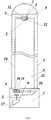
- Fig. 1 shows one example of implementation of the lighting installation according to the claimed engineering solution.
- the lighting installation comprises a base 1, an inflatable shell 2 filled with air and secured to the base 1, an air blower 3 mounted in the base and communicated with atmosphere and with a chamber 4 of the shell.
- At least one electric light source 5 is placed inside the shell 2 (four light sources are shown in Fig. 1 ) and is connected to a power source by an electric cord (not shown).
- the light source 5 is fastened to the shell 2 via a flange 6 and fasteners 7.
- a powerful LED light source is used in the installation, which emits a considerable amount of heat.
- the lighting installation is equipped with a heatsink 8 installed in the base 1 and positioned on an axis of air flow moving from the air blower 3.
- the heatsink 8 is filled with a liquid coolant.
- a hydraulic pump 9 and an expansion tank 10 are sequentially communicated with the heatsink 8, and the expansion tank 10 is communicated with a discharge pipe 11.
- the heatsink 8, the hydraulic pump 9 and the expansion tank 10 are installed inside the base 1 (see Fig. 1 ); in another non-claimed embodiment, they may be installed outside the base 1.
- the heatsink 8 is communicated with a hollow unit 12 configured to bear the light source 5 and to provide cooling the light source 5.
- a hermetic cave 13 of the hollow unit 12 is filled with the liquid coolant and is communicated with the heatsink 8 by a pressure pipe 14. If a single light source 5 is used, it is mounted on the lower side of the hollow unit 12; if several light sources 5 are used, they are mounted on different sides of the hollow unit 12.
- the lighting installation may comprise several hollow units 12 positioned at the same height or positioned one above another or in any other combinations.
- the pipes 11 and 14 are flexible and resilient. The pipes 11 and 14 may be spiral-shaped so as to increase heat dissipation and avoid twisting thereof.
- the above-indicated hydraulic components form a liquid cooling system for the LED light source 5.
- the heatsink 8 which is one of main components of the cooling system, has heat exchanging ribs 15 on its outer surface, wherein the ribs are directed along an air flow forced from bottom to top by the air blower 3. This air flow passes through passages 16 between the ribs 15.
- the cooling system may be used without the heatsink 8 under some conditions (favorable climate, low power of the light source, low liquid velocity in the cooling circuit). In this case, heat dissipation happens directly through the walls of the pipes 11 and 14.
- the hollow unit 12 has input and output openings with corresponding sleeves communicated with the pipes 11 and 14. If several hollow units 12 are used, they may be incorporated into a single circuit of a cooling system, either in parallel or in series; otherwise, each of the hollow units 12 may have an autonomous cooling system.
- the installation is equipped with a power unit 17.
- the power unit 17 may comprise an electric generator and an internal combustion engine, or an electric accumulator (not shown).
- the installation is also equipped with startup and adjustment equipment and with control means (not shown).
- the installation operates as follows. Electric current is fed from the power unit 17 to the air blower 3. Rotation of the air blower 3 causes atmospheric air to be forced into the chamber 4 of the shell 2, so the shell gets inflated and rises up along with the hollow unit 12, the light source 5 and the pipes 11 and 14, all attached to the shell. Electric current is fed from the power unit 17 to the LED light source 5, which heats the hollow unit 12 during operation. Electric current is also fed to the hydraulic pump 9, which pumps the liquid coolant through the following root of the cooling system: the hydraulic pump 9 - the heatsink 8 - the pipe 14 - the cave 13 of the hollow unit 12 - the pipe 11 - the expansion tank 10 - the hydraulic pump 9. While the liquid coolant travels through the above-indicated root, it takes heat from the hollow unit 12, which is heated from the light source 5, and loses heat in the heatsink 8. The light source 5 is cooled by the liquid coolant through a wall of the hollow unit 12.
- Heated liquid coolant forced by the hydraulic pump 9 into the heatsink 8 is cooled in the heatsink 8 so as the heat is drawn from the liquid coolant via the ribs 15 of the heatsink 8, which are blown by the air blower 3 during its operation. After cooling in the heatsink 8, the liquid coolant is fed into the cave 13 of the hollow unit 12 and the above-indicated operational cycle is repeated.
- Configuration of the lighting installation allows substantial increasing its power and luminous flux of the light sources owing to use of an effective liquid cooling system with a heatsink blown by a constantly working air blower of the installation.
- Use of LED light sources makes illumination of a territory more effective in comparison with known solutions of prior art.
- Reliability of the installation is also improved owing to increased thermal stability and enhanced endurance of the light source against mechanical impact.
- components of the cooling system may be positioned in the installation base or even apart from the installation, therefore weight of the upper part of the installation may be considerably reduced, and its size in operational position and power consumption may also be decreased.
Description
- The engineering solution relates to means for illuminating a territory, mainly under emergency conditions. It is intended for use, when electric power is off due to emergency or disaster, and also during construction works, repair works or search-and-rescue operations in the night time.
- Some inflatable lighting installations are known from patent publications (
US 6322230 B1 , published on 27.11.2001;RU 2192581 C1 RU 2286510 C9 WO 02/063207 A1 US 2008/291681 A1 published on 27.11.2008), each of which comprises an elastic inflatable shell providing a support for a light source secured inside the shell in the upper part thereof, wherein the support comprises a base linked to ground or any usual structural load-bearing member (a floor, a building, a frame). - A drawback of the known lighting installations is that they are not configured for using LED (light emitting diode) light sources for illuminating, which would provide an illumination level comparable with conventional gas-discharge lamps, in particular, with sodium-vapor lamps commonly used in such installations.
- A known emergency lighting installation (
RU 139894 U1 - This installation does not contribute to solving the problem of illuminating a territory with LED light sources, as emergency installations like this do not have means for guaranteed cooling powerful LED light sources. The LED-based strob lamp is intended for signaling only and it cannot be used for providing illumination.
- Meanwhile, LED light sources have a number of substantial advantages in comparison to other known light sources, namely, they have longer life time and lower power consumption; they are steadily operable in a wide temperature range; they start immediately after powering on and provide a high contrast, which promotes better clearness of the illuminated objects.
- However, a heatsink is required to ensure reliable operation of LEDs. In particular, there is a known lighting device (
RU 77024 U1 - Using devices similar to the above-indicated one in inflatable lighting installations does not comply with relevant requirements regarding illumination, as these installations are mainly used for illumination of large areas during works related to a high level of danger like accident elimination, disaster elimination, etc., when a substantially higher illumination level is required.
- Increase in number and power of LED light sources inevitably causes the need of increasing heat-removing surface of a heatsink and, consequently, to raising its size and weight. There is a known extra-high-power LED floodlight (
RU 144224 U1 - Using a massive heatsink in inflatable lighting installations deteriorates their operational performance, as lifting a light source equipped with such a heatsink by means of an air flow forced into an inflatable shell may be difficult, even impossible in some cases, due to large weight of the heatsink and necessity of maintaining greater pressure inside the shell. Moreover, the heatsink combined with the light source may fall down upon deflation of the shell, and it may cause personal injury of staff and damage of the installation.
- The claimed invention is directed at providing an inflatable lighting installation equipped with a LED light source ensuring a high illumination level, with no sufficient increasing weight of the installation upper part in an operational position thereof.
- A technical result attained by a lighting installation described herein is enhanced reliability and improved operational performance of the installation.
- The technical result is attained by a lighting installation according to
claim 1, the lighting installation comprising a base, an inflatable shell secured to the base, an air blower communicated to a chamber formed by the shell, and at least one electric light source placed inside the shell, wherein the lighting installation is equipped with a hollow unit secured inside the shell; the light source is installed on the hollow unit; a cave of the hollow unit is communicated with a cooling system for the light source; the light source is a LED light source; the cooling system is a liquid cooling system; and the cooling system comprises a pump communicated with the cave of the hollow unit by flexible pipes. The cooling system is equipped with a heatsink and an expansion tank. - In some embodiments of the lighting installation, the pipes may be spiral-shaped and may be secured to the shell; the heatsink may be placed on a longitudinal axis of the air blower. The cooling system is positioned inside the lighting installation. In a non-claimed embodiment, the cooling system is positioned outside the lighting system.
-
Fig. 1 shows one example of implementation of the lighting installation according to the claimed engineering solution. - The lighting installation comprises a
base 1, aninflatable shell 2 filled with air and secured to thebase 1, anair blower 3 mounted in the base and communicated with atmosphere and with achamber 4 of the shell. At least oneelectric light source 5 is placed inside the shell 2 (four light sources are shown inFig. 1 ) and is connected to a power source by an electric cord (not shown). Thelight source 5 is fastened to theshell 2 via aflange 6 andfasteners 7. A powerful LED light source is used in the installation, which emits a considerable amount of heat. In order to remove the heat and to prevent overheating thelight source 5, the lighting installation is equipped with aheatsink 8 installed in thebase 1 and positioned on an axis of air flow moving from theair blower 3. Theheatsink 8 is filled with a liquid coolant. A hydraulic pump 9 and anexpansion tank 10 are sequentially communicated with theheatsink 8, and theexpansion tank 10 is communicated with adischarge pipe 11. In one embodiment of the installation, theheatsink 8, the hydraulic pump 9 and theexpansion tank 10 are installed inside the base 1 (seeFig. 1 ); in another non-claimed embodiment, they may be installed outside thebase 1. - The
heatsink 8 is communicated with ahollow unit 12 configured to bear thelight source 5 and to provide cooling thelight source 5. Ahermetic cave 13 of thehollow unit 12 is filled with the liquid coolant and is communicated with theheatsink 8 by apressure pipe 14. If asingle light source 5 is used, it is mounted on the lower side of thehollow unit 12; ifseveral light sources 5 are used, they are mounted on different sides of thehollow unit 12. The lighting installation may comprise severalhollow units 12 positioned at the same height or positioned one above another or in any other combinations. Thepipes pipes - The above-indicated hydraulic components form a liquid cooling system for the
LED light source 5. Theheatsink 8, which is one of main components of the cooling system, hasheat exchanging ribs 15 on its outer surface, wherein the ribs are directed along an air flow forced from bottom to top by theair blower 3. This air flow passes throughpassages 16 between theribs 15. - Owing to a high heat capacity of the liquid coolant, the cooling system may be used without the
heatsink 8 under some conditions (favorable climate, low power of the light source, low liquid velocity in the cooling circuit). In this case, heat dissipation happens directly through the walls of thepipes - The
hollow unit 12 has input and output openings with corresponding sleeves communicated with thepipes hollow units 12 are used, they may be incorporated into a single circuit of a cooling system, either in parallel or in series; otherwise, each of thehollow units 12 may have an autonomous cooling system. - The installation is equipped with a
power unit 17. In different embodiments, thepower unit 17 may comprise an electric generator and an internal combustion engine, or an electric accumulator (not shown). The installation is also equipped with startup and adjustment equipment and with control means (not shown). - The installation operates as follows. Electric current is fed from the
power unit 17 to theair blower 3. Rotation of theair blower 3 causes atmospheric air to be forced into thechamber 4 of theshell 2, so the shell gets inflated and rises up along with thehollow unit 12, thelight source 5 and thepipes power unit 17 to theLED light source 5, which heats thehollow unit 12 during operation. Electric current is also fed to the hydraulic pump 9, which pumps the liquid coolant through the following root of the cooling system: the hydraulic pump 9 - the heatsink 8 - the pipe 14 - thecave 13 of the hollow unit 12 - the pipe 11 - the expansion tank 10 - the hydraulic pump 9. While the liquid coolant travels through the above-indicated root, it takes heat from thehollow unit 12, which is heated from thelight source 5, and loses heat in theheatsink 8. Thelight source 5 is cooled by the liquid coolant through a wall of thehollow unit 12. - Heated liquid coolant forced by the hydraulic pump 9 into the
heatsink 8 is cooled in theheatsink 8 so as the heat is drawn from the liquid coolant via theribs 15 of theheatsink 8, which are blown by theair blower 3 during its operation. After cooling in theheatsink 8, the liquid coolant is fed into thecave 13 of thehollow unit 12 and the above-indicated operational cycle is repeated. - Configuration of the lighting installation allows substantial increasing its power and luminous flux of the light sources owing to use of an effective liquid cooling system with a heatsink blown by a constantly working air blower of the installation. Use of LED light sources makes illumination of a territory more effective in comparison with known solutions of prior art. Reliability of the installation is also improved owing to increased thermal stability and enhanced endurance of the light source against mechanical impact. It should be noted that components of the cooling system may be positioned in the installation base or even apart from the installation, therefore weight of the upper part of the installation may be considerably reduced, and its size in operational position and power consumption may also be decreased.
Claims (4)
- A lighting installation comprising a base (1), an inflatable shell (2) secured to the base (1), an air blower (3) communicated with a chamber (4) formed by the shell (2), at least one electric LED light source (5) placed inside the shell (2), and at least one hollow unit (12) secured inside the shell (2), the light source being installed on the hollow unit (12), wherein the hollow unit (12) and the light source (5) are attached to the shell, characterized in that the lighting installation is equipped with:- a cave (13) of the hollow unit (12) communicating with a cooling system for the light source (5);- the cooling system is a liquid cooling system;- the cooling system comprises a hydraulic pump (9) communicating with the cave (13) of the hollow unit (12) by flexible pipes (11, 14);- the cooling system is equipped with a heatsink (8) and with an expansion tank (10);- the heatsink (8), the hydraulic pump (9) and the expansion tank (10) are installed inside the base (1); wherein rotation of the air blower (3) causes atmospheric air to be forced into the chamber (4) of the shell (2), so the shell (2) gets inflated and rises up along with the hollow unit (12), the light source (5) and the pipes.
- The lighting installation of claim 1, characterized in that the pipes (11, 14) are spiral-shaped.
- The lighting installation of claim 1, characterized in that the pipes (11, 14) are secured to the shell (2).
- The lighting installation of claim 1, characterized in that the heatsink (8) is positioned on a longitudinal axis of the air blower (3).
Applications Claiming Priority (2)
| Application Number | Priority Date | Filing Date | Title |
|---|---|---|---|
| EA201500359A EA028004B1 (en) | 2015-04-07 | 2015-04-07 | Lighting installation |
| PCT/RU2016/000187 WO2016163919A1 (en) | 2015-04-07 | 2016-04-04 | Lighting installation |
Publications (3)
| Publication Number | Publication Date |
|---|---|
| EP3282176A1 EP3282176A1 (en) | 2018-02-14 |
| EP3282176A4 EP3282176A4 (en) | 2018-10-24 |
| EP3282176B1 true EP3282176B1 (en) | 2020-03-18 |
Family
ID=57072817
Family Applications (1)
| Application Number | Title | Priority Date | Filing Date |
|---|---|---|---|
| EP16776983.5A Active EP3282176B1 (en) | 2015-04-07 | 2016-04-04 | Lighting installation |
Country Status (4)
| Country | Link |
|---|---|
| EP (1) | EP3282176B1 (en) |
| AU (1) | AU2016244708B2 (en) |
| EA (1) | EA028004B1 (en) |
| WO (1) | WO2016163919A1 (en) |
Families Citing this family (2)
| Publication number | Priority date | Publication date | Assignee | Title |
|---|---|---|---|---|
| US11287103B2 (en) | 2019-04-22 | 2022-03-29 | Ism Lighting, Llc. | Low wattage balloon work light |
| RU194196U1 (en) * | 2019-10-11 | 2019-12-03 | Владислав Гумарович Галимов | Lighting installation |
Family Cites Families (17)
| Publication number | Priority date | Publication date | Assignee | Title |
|---|---|---|---|---|
| US3741172A (en) * | 1970-08-05 | 1973-06-26 | Renault | Cooling system expansion chambers |
| US6527418B1 (en) * | 1997-05-27 | 2003-03-04 | Scherba Industries, Inc. | Light cooler |
| ITVE980007U1 (en) * | 1998-03-16 | 1999-09-16 | Medici Guido | EMERGENCY LIGHTING KIT WITH INFLATED STRUCTURE WITH AIR SOF FIANTE |
| ITMS20010002A1 (en) * | 2001-02-07 | 2002-08-07 | Marco Tambini | INFLATABLE EMERGENCY LIGHTING SYSTEM |
| RU2192581C1 (en) * | 2001-02-26 | 2002-11-10 | Налогин Дмитрий Олегович | Emergency lighting plant |
| DE102004036179A1 (en) * | 2004-07-26 | 2006-03-23 | Degussa Ag | Coolant line |
| CN101078507A (en) * | 2006-05-24 | 2007-11-28 | 曹嘉灿 | Light source illumination system |
| CA2590070A1 (en) * | 2007-05-25 | 2008-11-25 | Thomas Appleton | Inflatable portable lamp |
| DE102007029179A1 (en) * | 2007-06-25 | 2009-01-08 | BSH Bosch und Siemens Hausgeräte GmbH | The refrigerator |
| KR200438525Y1 (en) * | 2007-09-10 | 2008-02-26 | 티엠컨버전스주식회사 | Cooling device for led light source using non-conductive liquid |
| GB2465493B (en) * | 2008-11-25 | 2011-07-27 | Stanley Electric Co Ltd | Liquid-cooled LED lighting device |
| GB2469551B (en) * | 2009-04-15 | 2013-11-20 | Stanley Electric Co Ltd | Liquid-cooled led lighting device |
| CN201496782U (en) * | 2009-05-25 | 2010-06-02 | 北京科力康技贸有限公司 | Box type aeration rescue illuminating lamp |
| RU2487296C2 (en) * | 2011-04-19 | 2013-07-10 | Роман Дмитриевич Давыденко | Illumination device |
| CN202927577U (en) * | 2012-11-27 | 2013-05-08 | 姚晓乌 | High-strength LED (Light-Emitting Diode) light source |
| DE202013005254U1 (en) * | 2013-06-10 | 2013-07-01 | Anh Minh Do | LED spotlight with water cooling system |
| CN104197292A (en) * | 2014-09-16 | 2014-12-10 | 合肥徽彩电子科技有限公司 | Novel high-power LED radiating device |
-
2015
- 2015-04-07 EA EA201500359A patent/EA028004B1/en not_active IP Right Cessation
-
2016
- 2016-04-04 AU AU2016244708A patent/AU2016244708B2/en not_active Ceased
- 2016-04-04 EP EP16776983.5A patent/EP3282176B1/en active Active
- 2016-04-04 WO PCT/RU2016/000187 patent/WO2016163919A1/en unknown
Non-Patent Citations (1)
| Title |
|---|
| None * |
Also Published As
| Publication number | Publication date |
|---|---|
| EP3282176A1 (en) | 2018-02-14 |
| EA028004B1 (en) | 2017-09-29 |
| EP3282176A4 (en) | 2018-10-24 |
| WO2016163919A1 (en) | 2016-10-13 |
| EA201500359A1 (en) | 2016-10-31 |
| AU2016244708B2 (en) | 2018-09-27 |
| AU2016244708A1 (en) | 2017-11-23 |
Similar Documents
| Publication | Publication Date | Title |
|---|---|---|
| JP5635560B2 (en) | Balloon type floodlight | |
| EP3282176B1 (en) | Lighting installation | |
| KR20100132108A (en) | A street light | |
| US11287103B2 (en) | Low wattage balloon work light | |
| KR101068315B1 (en) | Water cooling led lamp for bio-photoreactor | |
| KR100898062B1 (en) | Led lighter having air channel | |
| KR20110061927A (en) | Led street light and security light | |
| JP6389837B2 (en) | Floodlight | |
| KR101264192B1 (en) | An air signboard equipped with led module | |
| ATE513163T1 (en) | LIGHTING DEVICE | |
| KR101115316B1 (en) | illumination lamp case for light emitting diode of light source | |
| KR20140122576A (en) | Lighting device | |
| RU161732U1 (en) | Convection Cooled LED Luminaire | |
| CN108343919B (en) | Breathing lamp | |
| KR101330698B1 (en) | Balloon illuminator | |
| KR102011497B1 (en) | Lifting structure of led lighting fixtures | |
| CN104832833A (en) | Ultraviolet sterilization and illumination integrated lamp | |
| KR101603299B1 (en) | Light lantern | |
| US11105485B2 (en) | LED lighting system in inflatable tower | |
| KR100581392B1 (en) | Medium Intensity Avitation Obstruction Light | |
| KR20180094195A (en) | Light lantern | |
| RU2540398C1 (en) | Industrial led lighting fixture | |
| KR100925490B1 (en) | Power LED Lamp with Rectangular Light Distribution | |
| KR20170003380U (en) | Support Apparatus For Balloon Typed Sign | |
| KR20110112500A (en) | A led street lamp |
Legal Events
| Date | Code | Title | Description |
|---|---|---|---|
| STAA | Information on the status of an ep patent application or granted ep patent |
Free format text: STATUS: THE INTERNATIONAL PUBLICATION HAS BEEN MADE |
|
| PUAI | Public reference made under article 153(3) epc to a published international application that has entered the european phase |
Free format text: ORIGINAL CODE: 0009012 |
|
| STAA | Information on the status of an ep patent application or granted ep patent |
Free format text: STATUS: REQUEST FOR EXAMINATION WAS MADE |
|
| 17P | Request for examination filed |
Effective date: 20171107 |
|
| AK | Designated contracting states |
Kind code of ref document: A1 Designated state(s): AL AT BE BG CH CY CZ DE DK EE ES FI FR GB GR HR HU IE IS IT LI LT LU LV MC MK MT NL NO PL PT RO RS SE SI SK SM TR |
|
| AX | Request for extension of the european patent |
Extension state: BA ME |
|
| DAV | Request for validation of the european patent (deleted) | ||
| DAX | Request for extension of the european patent (deleted) | ||
| A4 | Supplementary search report drawn up and despatched |
Effective date: 20180924 |
|
| RIC1 | Information provided on ipc code assigned before grant |
Ipc: F21Y 115/10 20160101ALN20180918BHEP Ipc: F21V 29/58 20150101ALI20180918BHEP Ipc: F21V 3/02 20060101ALI20180918BHEP Ipc: F21S 9/04 20060101ALN20180918BHEP Ipc: F21S 8/00 20060101AFI20180918BHEP Ipc: F21V 29/00 20150101ALI20180918BHEP Ipc: F21V 21/10 20060101ALI20180918BHEP |
|
| GRAP | Despatch of communication of intention to grant a patent |
Free format text: ORIGINAL CODE: EPIDOSNIGR1 |
|
| STAA | Information on the status of an ep patent application or granted ep patent |
Free format text: STATUS: GRANT OF PATENT IS INTENDED |
|
| RIC1 | Information provided on ipc code assigned before grant |
Ipc: F21Y 115/10 20160101ALN20190912BHEP Ipc: F21V 29/58 20150101ALI20190912BHEP Ipc: F21S 9/04 20060101ALN20190912BHEP Ipc: F21S 8/00 20060101AFI20190912BHEP Ipc: F21V 29/00 20150101ALI20190912BHEP Ipc: F21V 3/02 20060101ALI20190912BHEP Ipc: F21V 21/10 20060101ALI20190912BHEP |
|
| INTG | Intention to grant announced |
Effective date: 20191010 |
|
| GRAS | Grant fee paid |
Free format text: ORIGINAL CODE: EPIDOSNIGR3 |
|
| GRAA | (expected) grant |
Free format text: ORIGINAL CODE: 0009210 |
|
| STAA | Information on the status of an ep patent application or granted ep patent |
Free format text: STATUS: THE PATENT HAS BEEN GRANTED |
|
| AK | Designated contracting states |
Kind code of ref document: B1 Designated state(s): AL AT BE BG CH CY CZ DE DK EE ES FI FR GB GR HR HU IE IS IT LI LT LU LV MC MK MT NL NO PL PT RO RS SE SI SK SM TR |
|
| REG | Reference to a national code |
Ref country code: GB Ref legal event code: FG4D |
|
| REG | Reference to a national code |
Ref country code: DE Ref legal event code: R096 Ref document number: 602016032124 Country of ref document: DE |
|
| REG | Reference to a national code |
Ref country code: AT Ref legal event code: REF Ref document number: 1246302 Country of ref document: AT Kind code of ref document: T Effective date: 20200415 Ref country code: IE Ref legal event code: FG4D |
|
| PG25 | Lapsed in a contracting state [announced via postgrant information from national office to epo] |
Ref country code: NO Free format text: LAPSE BECAUSE OF FAILURE TO SUBMIT A TRANSLATION OF THE DESCRIPTION OR TO PAY THE FEE WITHIN THE PRESCRIBED TIME-LIMIT Effective date: 20200618 Ref country code: RS Free format text: LAPSE BECAUSE OF FAILURE TO SUBMIT A TRANSLATION OF THE DESCRIPTION OR TO PAY THE FEE WITHIN THE PRESCRIBED TIME-LIMIT Effective date: 20200318 Ref country code: FI Free format text: LAPSE BECAUSE OF FAILURE TO SUBMIT A TRANSLATION OF THE DESCRIPTION OR TO PAY THE FEE WITHIN THE PRESCRIBED TIME-LIMIT Effective date: 20200318 |
|
| REG | Reference to a national code |
Ref country code: NL Ref legal event code: MP Effective date: 20200318 |
|
| PG25 | Lapsed in a contracting state [announced via postgrant information from national office to epo] |
Ref country code: HR Free format text: LAPSE BECAUSE OF FAILURE TO SUBMIT A TRANSLATION OF THE DESCRIPTION OR TO PAY THE FEE WITHIN THE PRESCRIBED TIME-LIMIT Effective date: 20200318 Ref country code: GR Free format text: LAPSE BECAUSE OF FAILURE TO SUBMIT A TRANSLATION OF THE DESCRIPTION OR TO PAY THE FEE WITHIN THE PRESCRIBED TIME-LIMIT Effective date: 20200619 Ref country code: LV Free format text: LAPSE BECAUSE OF FAILURE TO SUBMIT A TRANSLATION OF THE DESCRIPTION OR TO PAY THE FEE WITHIN THE PRESCRIBED TIME-LIMIT Effective date: 20200318 Ref country code: BG Free format text: LAPSE BECAUSE OF FAILURE TO SUBMIT A TRANSLATION OF THE DESCRIPTION OR TO PAY THE FEE WITHIN THE PRESCRIBED TIME-LIMIT Effective date: 20200618 Ref country code: SE Free format text: LAPSE BECAUSE OF FAILURE TO SUBMIT A TRANSLATION OF THE DESCRIPTION OR TO PAY THE FEE WITHIN THE PRESCRIBED TIME-LIMIT Effective date: 20200318 |
|
| REG | Reference to a national code |
Ref country code: LT Ref legal event code: MG4D |
|
| PG25 | Lapsed in a contracting state [announced via postgrant information from national office to epo] |
Ref country code: NL Free format text: LAPSE BECAUSE OF FAILURE TO SUBMIT A TRANSLATION OF THE DESCRIPTION OR TO PAY THE FEE WITHIN THE PRESCRIBED TIME-LIMIT Effective date: 20200318 |
|
| PG25 | Lapsed in a contracting state [announced via postgrant information from national office to epo] |
Ref country code: CZ Free format text: LAPSE BECAUSE OF FAILURE TO SUBMIT A TRANSLATION OF THE DESCRIPTION OR TO PAY THE FEE WITHIN THE PRESCRIBED TIME-LIMIT Effective date: 20200318 Ref country code: SK Free format text: LAPSE BECAUSE OF FAILURE TO SUBMIT A TRANSLATION OF THE DESCRIPTION OR TO PAY THE FEE WITHIN THE PRESCRIBED TIME-LIMIT Effective date: 20200318 Ref country code: IS Free format text: LAPSE BECAUSE OF FAILURE TO SUBMIT A TRANSLATION OF THE DESCRIPTION OR TO PAY THE FEE WITHIN THE PRESCRIBED TIME-LIMIT Effective date: 20200718 Ref country code: EE Free format text: LAPSE BECAUSE OF FAILURE TO SUBMIT A TRANSLATION OF THE DESCRIPTION OR TO PAY THE FEE WITHIN THE PRESCRIBED TIME-LIMIT Effective date: 20200318 Ref country code: LT Free format text: LAPSE BECAUSE OF FAILURE TO SUBMIT A TRANSLATION OF THE DESCRIPTION OR TO PAY THE FEE WITHIN THE PRESCRIBED TIME-LIMIT Effective date: 20200318 Ref country code: RO Free format text: LAPSE BECAUSE OF FAILURE TO SUBMIT A TRANSLATION OF THE DESCRIPTION OR TO PAY THE FEE WITHIN THE PRESCRIBED TIME-LIMIT Effective date: 20200318 Ref country code: SM Free format text: LAPSE BECAUSE OF FAILURE TO SUBMIT A TRANSLATION OF THE DESCRIPTION OR TO PAY THE FEE WITHIN THE PRESCRIBED TIME-LIMIT Effective date: 20200318 Ref country code: PT Free format text: LAPSE BECAUSE OF FAILURE TO SUBMIT A TRANSLATION OF THE DESCRIPTION OR TO PAY THE FEE WITHIN THE PRESCRIBED TIME-LIMIT Effective date: 20200812 |
|
| REG | Reference to a national code |
Ref country code: AT Ref legal event code: MK05 Ref document number: 1246302 Country of ref document: AT Kind code of ref document: T Effective date: 20200318 |
|
| REG | Reference to a national code |
Ref country code: CH Ref legal event code: PL |
|
| REG | Reference to a national code |
Ref country code: DE Ref legal event code: R097 Ref document number: 602016032124 Country of ref document: DE |
|
| PG25 | Lapsed in a contracting state [announced via postgrant information from national office to epo] |
Ref country code: MC Free format text: LAPSE BECAUSE OF FAILURE TO SUBMIT A TRANSLATION OF THE DESCRIPTION OR TO PAY THE FEE WITHIN THE PRESCRIBED TIME-LIMIT Effective date: 20200318 |
|
| PLBE | No opposition filed within time limit |
Free format text: ORIGINAL CODE: 0009261 |
|
| STAA | Information on the status of an ep patent application or granted ep patent |
Free format text: STATUS: NO OPPOSITION FILED WITHIN TIME LIMIT |
|
| PG25 | Lapsed in a contracting state [announced via postgrant information from national office to epo] |
Ref country code: AT Free format text: LAPSE BECAUSE OF FAILURE TO SUBMIT A TRANSLATION OF THE DESCRIPTION OR TO PAY THE FEE WITHIN THE PRESCRIBED TIME-LIMIT Effective date: 20200318 Ref country code: DK Free format text: LAPSE BECAUSE OF FAILURE TO SUBMIT A TRANSLATION OF THE DESCRIPTION OR TO PAY THE FEE WITHIN THE PRESCRIBED TIME-LIMIT Effective date: 20200318 Ref country code: LI Free format text: LAPSE BECAUSE OF NON-PAYMENT OF DUE FEES Effective date: 20200430 Ref country code: LU Free format text: LAPSE BECAUSE OF NON-PAYMENT OF DUE FEES Effective date: 20200404 Ref country code: IT Free format text: LAPSE BECAUSE OF FAILURE TO SUBMIT A TRANSLATION OF THE DESCRIPTION OR TO PAY THE FEE WITHIN THE PRESCRIBED TIME-LIMIT Effective date: 20200318 Ref country code: CH Free format text: LAPSE BECAUSE OF NON-PAYMENT OF DUE FEES Effective date: 20200430 Ref country code: ES Free format text: LAPSE BECAUSE OF FAILURE TO SUBMIT A TRANSLATION OF THE DESCRIPTION OR TO PAY THE FEE WITHIN THE PRESCRIBED TIME-LIMIT Effective date: 20200318 |
|
| REG | Reference to a national code |
Ref country code: BE Ref legal event code: MM Effective date: 20200430 |
|
| 26N | No opposition filed |
Effective date: 20201221 |
|
| PG25 | Lapsed in a contracting state [announced via postgrant information from national office to epo] |
Ref country code: PL Free format text: LAPSE BECAUSE OF FAILURE TO SUBMIT A TRANSLATION OF THE DESCRIPTION OR TO PAY THE FEE WITHIN THE PRESCRIBED TIME-LIMIT Effective date: 20200318 Ref country code: BE Free format text: LAPSE BECAUSE OF NON-PAYMENT OF DUE FEES Effective date: 20200430 |
|
| GBPC | Gb: european patent ceased through non-payment of renewal fee |
Effective date: 20200618 |
|
| PG25 | Lapsed in a contracting state [announced via postgrant information from national office to epo] |
Ref country code: GB Free format text: LAPSE BECAUSE OF NON-PAYMENT OF DUE FEES Effective date: 20200618 Ref country code: IE Free format text: LAPSE BECAUSE OF NON-PAYMENT OF DUE FEES Effective date: 20200404 Ref country code: FR Free format text: LAPSE BECAUSE OF NON-PAYMENT OF DUE FEES Effective date: 20200518 |
|
| PG25 | Lapsed in a contracting state [announced via postgrant information from national office to epo] |
Ref country code: SI Free format text: LAPSE BECAUSE OF FAILURE TO SUBMIT A TRANSLATION OF THE DESCRIPTION OR TO PAY THE FEE WITHIN THE PRESCRIBED TIME-LIMIT Effective date: 20200318 |
|
| PGFP | Annual fee paid to national office [announced via postgrant information from national office to epo] |
Ref country code: DE Payment date: 20210427 Year of fee payment: 6 |
|
| PG25 | Lapsed in a contracting state [announced via postgrant information from national office to epo] |
Ref country code: TR Free format text: LAPSE BECAUSE OF FAILURE TO SUBMIT A TRANSLATION OF THE DESCRIPTION OR TO PAY THE FEE WITHIN THE PRESCRIBED TIME-LIMIT Effective date: 20200318 Ref country code: MT Free format text: LAPSE BECAUSE OF FAILURE TO SUBMIT A TRANSLATION OF THE DESCRIPTION OR TO PAY THE FEE WITHIN THE PRESCRIBED TIME-LIMIT Effective date: 20200318 Ref country code: CY Free format text: LAPSE BECAUSE OF FAILURE TO SUBMIT A TRANSLATION OF THE DESCRIPTION OR TO PAY THE FEE WITHIN THE PRESCRIBED TIME-LIMIT Effective date: 20200318 |
|
| PG25 | Lapsed in a contracting state [announced via postgrant information from national office to epo] |
Ref country code: MK Free format text: LAPSE BECAUSE OF FAILURE TO SUBMIT A TRANSLATION OF THE DESCRIPTION OR TO PAY THE FEE WITHIN THE PRESCRIBED TIME-LIMIT Effective date: 20200318 Ref country code: AL Free format text: LAPSE BECAUSE OF FAILURE TO SUBMIT A TRANSLATION OF THE DESCRIPTION OR TO PAY THE FEE WITHIN THE PRESCRIBED TIME-LIMIT Effective date: 20200318 |
|
| REG | Reference to a national code |
Ref country code: DE Ref legal event code: R119 Ref document number: 602016032124 Country of ref document: DE |
|
| PG25 | Lapsed in a contracting state [announced via postgrant information from national office to epo] |
Ref country code: DE Free format text: LAPSE BECAUSE OF NON-PAYMENT OF DUE FEES Effective date: 20221103 |