EP3233544B1 - Motor vehicle chassis - Google Patents
Motor vehicle chassis Download PDFInfo
- Publication number
- EP3233544B1 EP3233544B1 EP15813335.5A EP15813335A EP3233544B1 EP 3233544 B1 EP3233544 B1 EP 3233544B1 EP 15813335 A EP15813335 A EP 15813335A EP 3233544 B1 EP3233544 B1 EP 3233544B1
- Authority
- EP
- European Patent Office
- Prior art keywords
- hydraulic
- line
- pump
- check valve
- valve
- Prior art date
- Legal status (The legal status is an assumption and is not a legal conclusion. Google has not performed a legal analysis and makes no representation as to the accuracy of the status listed.)
- Active
Links
- 239000012530 fluid Substances 0.000 claims description 19
- 239000000725 suspension Substances 0.000 claims description 16
- 230000002441 reversible effect Effects 0.000 claims description 11
- 230000004913 activation Effects 0.000 claims 1
- 230000000903 blocking effect Effects 0.000 description 3
- 238000011161 development Methods 0.000 description 3
- 230000010354 integration Effects 0.000 description 2
- 238000005086 pumping Methods 0.000 description 2
- 230000002195 synergetic effect Effects 0.000 description 2
- 238000011144 upstream manufacturing Methods 0.000 description 2
- 239000006096 absorbing agent Substances 0.000 description 1
- 230000002411 adverse Effects 0.000 description 1
- 238000013459 approach Methods 0.000 description 1
- 230000009286 beneficial effect Effects 0.000 description 1
- 238000010276 construction Methods 0.000 description 1
- 230000001419 dependent effect Effects 0.000 description 1
- 238000013461 design Methods 0.000 description 1
- 230000001627 detrimental effect Effects 0.000 description 1
- 238000005265 energy consumption Methods 0.000 description 1
- 238000009434 installation Methods 0.000 description 1
- 230000003993 interaction Effects 0.000 description 1
- 230000007257 malfunction Effects 0.000 description 1
- 238000012986 modification Methods 0.000 description 1
- 230000004048 modification Effects 0.000 description 1
- 230000035939 shock Effects 0.000 description 1
- 239000002689 soil Substances 0.000 description 1
- 238000012549 training Methods 0.000 description 1
Images


Classifications
-
- B—PERFORMING OPERATIONS; TRANSPORTING
- B60—VEHICLES IN GENERAL
- B60G—VEHICLE SUSPENSION ARRANGEMENTS
- B60G17/00—Resilient suspensions having means for adjusting the spring or vibration-damper characteristics, for regulating the distance between a supporting surface and a sprung part of vehicle or for locking suspension during use to meet varying vehicular or surface conditions, e.g. due to speed or load
- B60G17/02—Spring characteristics, e.g. mechanical springs and mechanical adjusting means
- B60G17/04—Spring characteristics, e.g. mechanical springs and mechanical adjusting means fluid spring characteristics
- B60G17/056—Regulating distributors or valves for hydropneumatic systems
-
- B—PERFORMING OPERATIONS; TRANSPORTING
- B60—VEHICLES IN GENERAL
- B60G—VEHICLE SUSPENSION ARRANGEMENTS
- B60G15/00—Resilient suspensions characterised by arrangement, location or type of combined spring and vibration damper, e.g. telescopic type
- B60G15/02—Resilient suspensions characterised by arrangement, location or type of combined spring and vibration damper, e.g. telescopic type having mechanical spring
- B60G15/06—Resilient suspensions characterised by arrangement, location or type of combined spring and vibration damper, e.g. telescopic type having mechanical spring and fluid damper
- B60G15/062—Resilient suspensions characterised by arrangement, location or type of combined spring and vibration damper, e.g. telescopic type having mechanical spring and fluid damper the spring being arranged around the damper
- B60G15/063—Resilient suspensions characterised by arrangement, location or type of combined spring and vibration damper, e.g. telescopic type having mechanical spring and fluid damper the spring being arranged around the damper characterised by the mounting of the spring on the damper
-
- B—PERFORMING OPERATIONS; TRANSPORTING
- B60—VEHICLES IN GENERAL
- B60G—VEHICLE SUSPENSION ARRANGEMENTS
- B60G17/00—Resilient suspensions having means for adjusting the spring or vibration-damper characteristics, for regulating the distance between a supporting surface and a sprung part of vehicle or for locking suspension during use to meet varying vehicular or surface conditions, e.g. due to speed or load
- B60G17/02—Spring characteristics, e.g. mechanical springs and mechanical adjusting means
- B60G17/027—Mechanical springs regulated by fluid means
- B60G17/0272—Mechanical springs regulated by fluid means the mechanical spring being a coil spring
-
- B—PERFORMING OPERATIONS; TRANSPORTING
- B60—VEHICLES IN GENERAL
- B60G—VEHICLE SUSPENSION ARRANGEMENTS
- B60G2202/00—Indexing codes relating to the type of spring, damper or actuator
- B60G2202/30—Spring/Damper and/or actuator Units
- B60G2202/31—Spring/Damper and/or actuator Units with the spring arranged around the damper, e.g. MacPherson strut
- B60G2202/312—The spring being a wound spring
-
- B—PERFORMING OPERATIONS; TRANSPORTING
- B60—VEHICLES IN GENERAL
- B60G—VEHICLE SUSPENSION ARRANGEMENTS
- B60G2202/00—Indexing codes relating to the type of spring, damper or actuator
- B60G2202/30—Spring/Damper and/or actuator Units
- B60G2202/32—The spring being in series with the damper and/or actuator
-
- B—PERFORMING OPERATIONS; TRANSPORTING
- B60—VEHICLES IN GENERAL
- B60G—VEHICLE SUSPENSION ARRANGEMENTS
- B60G2202/00—Indexing codes relating to the type of spring, damper or actuator
- B60G2202/40—Type of actuator
- B60G2202/41—Fluid actuator
- B60G2202/413—Hydraulic actuator
-
- B—PERFORMING OPERATIONS; TRANSPORTING
- B60—VEHICLES IN GENERAL
- B60G—VEHICLE SUSPENSION ARRANGEMENTS
- B60G2202/00—Indexing codes relating to the type of spring, damper or actuator
- B60G2202/40—Type of actuator
- B60G2202/41—Fluid actuator
- B60G2202/415—Fluid actuator using other types of valves, e.g. mechanically operated valves
-
- B—PERFORMING OPERATIONS; TRANSPORTING
- B60—VEHICLES IN GENERAL
- B60G—VEHICLE SUSPENSION ARRANGEMENTS
- B60G2202/00—Indexing codes relating to the type of spring, damper or actuator
- B60G2202/40—Type of actuator
- B60G2202/41—Fluid actuator
- B60G2202/416—Fluid actuator using a pump, e.g. in the line connecting the lower chamber to the upper chamber of the actuator
-
- B—PERFORMING OPERATIONS; TRANSPORTING
- B60—VEHICLES IN GENERAL
- B60G—VEHICLE SUSPENSION ARRANGEMENTS
- B60G2204/00—Indexing codes related to suspensions per se or to auxiliary parts
- B60G2204/10—Mounting of suspension elements
- B60G2204/12—Mounting of springs or dampers
- B60G2204/124—Mounting of coil springs
-
- B—PERFORMING OPERATIONS; TRANSPORTING
- B60—VEHICLES IN GENERAL
- B60G—VEHICLE SUSPENSION ARRANGEMENTS
- B60G2500/00—Indexing codes relating to the regulated action or device
- B60G2500/20—Spring action or springs
- B60G2500/203—Distributor valve units comprising several elements, e.g. valves, pump or accumulators
-
- B—PERFORMING OPERATIONS; TRANSPORTING
- B60—VEHICLES IN GENERAL
- B60G—VEHICLE SUSPENSION ARRANGEMENTS
- B60G2500/00—Indexing codes relating to the regulated action or device
- B60G2500/30—Height or ground clearance
- B60G2500/32—Height or ground clearance of only one vehicle part or side
Definitions
- the present invention relates to a motor vehicle chassis comprising a base structure and a plurality of wheels connected thereto via a respective wheel suspension, wherein each suspension has at least one spring and furthermore wherein at least one wheel suspension is associated with a hydraulic level adjustment device.
- the adjusting device engages in one of the base points of the spring of the relevant wheel suspension and changes it, wherein in principle it is not decisive whether the spring base is assigned to the basic structure or else to the wheel concerned.
- pneumatic and electric spring base adjustment drives are also known in particular hydraulic spring base adjustment drives, for example from the DE 3223195 A1 , of the DE 102009047100 A1 , of the US 5181696 A , of the EP 2301773 A1 , of the JP 2010-149550 A and the WO 2014/142160 A1 (corresponding EP 2851277 A1 ).
- the JP H02 81786 A discloses a hydraulic spring base adjustment drive.
- JP H02 81786 A a reversible hydraulic pump
- the two ports communicate on the one hand in each case one - arranged with flow direction to the pump - check valve and on the other hand one - with flow direction to the tank - pressure relief valve with the tank.
- One of the two pump outputs communicates with four single-acting hydraulic linear actuators via two hydraulically operated check valves, whereby the control inputs of the two pilot operated check valves are supplied via a control line from the second pump outlet.
- the hydraulic level-adjusting device comprises a single-acting hydraulic linear actuator whose (for lifting the base structure acted upon) working space via a line and valve assembly with a (first) pump port of Pump a hydraulic unit is connected.
- a check valve To hold raised position, a check valve provided, which has a biased by a closing spring in a locking position of the valve valve piston.
- the valve piston By applying an associated valve working space, the valve piston can be moved against the force of the closing spring and open the check valve in this way to drain the hydraulic fluid from the linear actuator and lower the base structure of the chassis in this way.
- the hydraulic unit is reversible, so that it is possible to switch between two delivery directions.
- the line and valve arrangement connects the second pump connection to the valve working chamber of the check valve and, moreover, comprises a 3/3-way valve which connects the two pump connections and whose third connection is connected to the supply container.
- the 3/3-way valve is spring biased biased in a blocking position, from which it actuated control pressure dependent connects either the first or the second pump port to the reservoir.
- the present invention is directed to provide a motor vehicle chassis of the type described above, that by a characterized increased practicality, while reducing the apparatus cost over the prior art.
- the motor vehicle chassis according to the invention with hydraulic level adjustment by the following, in a synergetic manner functionally interacting features:
- the hydraulic level adjustment is completely arranged on the suspension and includes a reservoir for hydraulic fluid, a hydraulic unit with one by an electric motor driven, two pump ports having hydraulic pump, a single-acting hydraulic linear actuator and a reservoir, the hydraulic pump and the linear actuator interconnecting line and valve assembly.
- a first pump connection is connected via a filling line with a filling check valve disposed therein with the working space of the hydraulic linear actuator.
- the hydraulic unit is reversible with a reversible between the two pump connections conveying direction.
- the two pump connections are connected via a shuttle valve to the reservoir.
- the shuttle valve is designed to be self-sufficient without actuated by external energy control and has no blocking position, so that constantly communicates at least one of the two pump ports via the shuttle valve to the reservoir.
- the second pump connection is connected via an outflow line with a throttling unit arranged therein with the reservoir.
- a control line connects the control port of a pilot-operated drain check valve, which in a working space of the hydraulic linear actuator with the Reservoir connecting drain line is arranged, with the discharge line between the second pump port and the throttle unit.
- the chassis according to the invention level adjustment without any externally controlled, ie in particular without any electrically controlled valve can get along, there is a special feature of the chassis according to the invention in that the second pump port, a pure discharge line is connected. This contributes in synergetic interaction with the other for this determining characteristics essential to the particular usefulness of the chassis according to the invention.
- the hydraulic unit does not promote in his reverse second conveying direction on a hydraulic fluid consuming consumer (such as a work space or the like); Rather, the hydraulic unit pumps in this mode, the pumped hydraulic fluid through the outflow - against the resistance of the flow restrictor - completely back into the reservoir, apart from the (minimum) amount of hydraulic fluid, which at start-up of the hydraulic pump in its second conveying direction via the control line on the Control terminal of the arranged in the drain line unlockable drain check valve is given to open this, ie switch to passage.
- the second pump connection in the sense directly to the control port of the arranged in the discharge line is switched, that the pressure prevailing at the second pump port hydraulic pressure is constantly applied to the control port of the pilot-operated drain check valve.
- the shuttle valve via which the two pump ports are connected to the reservoir , executed independently without an actuated by external energy control.
- the only controlled by the applied pressures shuttle valve unlike that according to the WO 2014/142160 A1 provided 3/3-way valve no blocking position, so that constantly communicates at least one of the two pump connections via the shuttle valve to the reservoir.
- chassis level adjustment in particular the possibility of a particularly compact design with minimal dimensions, make the hydraulic adjustment in a special way suitable for integration into the respective suspension.
- the respective hydraulic adjusting completely arranged on the relevant suspension, which in particular includes that each equipped with a hydraulic level adjustment wheel suspension is assigned its own hydraulic unit.
- a first preferred embodiment of the invention is characterized in that a flow restrictor, i. a separate, independent of the throttle behavior of the releasable drain check valve throttle element is arranged.
- This flow restrictor i. its throttle behavior, is determinative of the dynamics of lowering the chassis, when the hydraulic pump is switched to its second conveying direction and the unlockable drain check valve is thereby opened.
- the lowering of the chassis can be optimized without having to take into account the flow situation within the releasable drain check valve, which in turn can be optimized for its function of keeping the chassis at its respective set level.
- the pilot-operated check valve arranged in the hydraulic working line is designed in two stages with two individual valves connected in series with control connections connected in parallel.
- a redundancy provided in this manner by the said valve group makes it possible to use relatively inexpensive pilot operated check valves, without this having a detrimental effect on the reliability of the level adjustment device as a whole.
- valve group with two series-connected pilot operated check valves with parallel control terminals can, according to yet another preferred development (arranged in the hydraulic working line, ie in turn flowed through both when lifting and when lowering) valve group with a pilot-operated check valve and a series-connected throttle check valve may be provided.
- the throttle check valve assumes the function of the already mentioned above, arranged in the discharge line flow restrictor.
- the line and valve arrangement preferably comprises an emergency drainage line which connects the working space of the hydraulic linear actuator to the discharge line and into which a manually actuated shut-off valve is connected.
- an emergency drainage line which connects the working space of the hydraulic linear actuator to the discharge line and into which a manually actuated shut-off valve is connected.
- the chassis By manually opening the said check valve, the chassis can be lowered in case of failure of the hydraulic unit or other malfunction by hydraulic fluid locked in the working space of the hydraulic linear actuator is discharged via the discharge line into the reservoir.
- the emergency drain line opens into the outflow line upstream of the throttle unit arranged therein.
- the throttling unit arranged in the outflow line comprises, according to a again particularly preferred development, an aperture. This ensures - via the aperture - at rest system, a pressure equalization between the control port of the pilot-off drain check valve and the Vorrast testinger.
- the throttle unit may also include a pressure relief valve instead of the diaphragm (or possibly in addition to this).
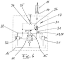
- FIG. 1 has - in view of the extent existing state of the art (see above) only schematically illustrated - the chassis 1 of a motor vehicle 2 on several wheels 3, which are each connected via a suspension 4 with a base structure 5.
- the suspension 4 in each case comprises a spring 6 and other conventional components such as a shock absorber. 7
- hydraulic level adjustment device 8 which is intended in particular for structural integration in the suspension 4, comprises a - known in such a way the change of (for example, wheel side) foot 9 of the spring 6 of the suspension 4 causing - single-acting, a work space 10 having hydraulic linear actuator 11, a reversible hydraulic unit 12 with a driven by an electric motor M, a first pump port 13 and a second pump port 14 having hydraulic pump 15, a reservoir 16 for hydraulic fluid and a reservoir 16, the hydraulic pump 15 and the linear actuator 11 interconnecting line and valve assembly 17.
- the first pump port 13 and the second pump port 14 are connected via a shuttle valve 18 to the reservoir 16.
- the shuttle valve 18 is executed self-sufficient; in the case of an existing between the two pump ports 13, 14 pressure difference of the pumping circuit communicates with a lower pressure level via the shuttle valve 18 to the reservoir 16, whereas the pumping circuit is locked with higher pressure level to the reservoir 16 out.
- the working space 10 of the linear actuator 11 can be acted upon by the hydraulic pump 15 (operated with the first conveying direction A).
- the first pump connection 13 is connected via a filling line 19 to the working space 10 of the hydraulic linear actuator 11.
- the hydraulic pump 15 sucks hydraulic fluid through the second pump port 14 and the shuttle valve 18 the reservoir 16 at.
- a filling check valve 20 is arranged in the filling 19, arranged. This prevents reverse flow through the filling line 19.
- a pressure limiting valve 21 is provided which prevents an inadmissibly high pressure rise in the filling line 19 by opening a connection of the first pump connection 13 to the reservoir 16 when a predetermined pressure level is exceeded.
- the hydraulic pump 15 stops.
- the hydraulic fluid pumped into the working space 10 of the linear actuator 11 remains locked there.
- the hydraulic pump 15 is operated with the reverse, second conveying direction B.
- the shuttle valve 18 controls.
- the hydraulic pump 15 now draws in hydraulic fluid via the first pump port 13 and the shuttle valve 18 from the reservoir 16 and conveys them via the second pump port 14 and a discharge line 22 with a therein arranged, formed by a shutter 23 throttle unit 24 in the reservoir 16 back.
- the existing in the discharge line 22 upstream of the aperture 23 is connected via a control line 25, which connects the discharge line 22 to the control port 26 of a releasable drain check valve 27, to the control port 26 of the pilot-off drain check valve 27.
- the releasable drain check valve 27 opens.
- the hydraulic pump 15 stops.
- the drain check valve 27 closes. And remaining in the working space 10 of the linear actuator 11 hydraulic fluid remains trapped there. From this position, the chassis 1 can be further lowered in the manner described above, if necessary, or raised again.
- FIG. 12 illustrates a modification of FIG Fig. 1 shown hydraulic level adjustment device 8 of a motor vehicle chassis 1 such that two after Fig. 1 structurally separate valves, namely the filling check valve 20 and the releasable drain check valve 27 are combined into a single, both functions in self-unifying pilot-operated check valve 30.
- the corresponding unlockable check valve 30 is arranged in a hydraulic working line 31, which forms both a portion of the filling line 19 and a portion of the drain line 28.
- the function of in Fig. 2 shown hydraulic level adjustment device 8 agrees with that of the hydraulic level adjustment device 8 Fig.
- Fig. 3 shown third embodiment of the hydraulic level adjustment device 8 of a motor vehicle chassis 1 largely corresponds to those after Fig. 2 ,
- the throttle unit 24 is realized instead of by a diaphragm by a pressure relief valve 32.
- pilot-operated check valve 30 is designed in two stages with two series-connected individual valves 30a, 30b with parallel control terminals 26a, 26b.
- a throttle check valve 33 is provided in series with the releasable check valve 30 arranged there switched. This allows an unthrottled filling of the working space 10 of the linear actuator 11 when lifting the motor vehicle chassis 1 (conveying direction A of the hydraulic pump 15), whereas when lowering the chassis 1 (conveying direction B of the hydraulic pump 15), the return flow of the hydraulic fluid from the working space 10 of the linear actuator eleventh throttled into the reservoir 16.
- the throttle check valve 33 takes over so far the function of the flow restrictor 29 in Fig. 1 shown hydraulic level adjustment device. 8
- the line and valve assembly 17 includes an emergency drain line 34 which connects the working space 10 of the hydraulic linear actuator 11 with the discharge line 22 and into which a manually actuated shut-off valve 35 is connected.
Landscapes
- Engineering & Computer Science (AREA)
- Mechanical Engineering (AREA)
- Vehicle Body Suspensions (AREA)
- Fluid-Pressure Circuits (AREA)
Description
Die vorliegende Erfindung betrifft ein Kraftfahrzeug-Fahrgestell, umfassend eine Basisstruktur und eine Mehrzahl von mit dieser über jeweils eine Radaufhängung verbundenen Rädern, wobei jede Radaufhängung mindestens eine Feder aufweist und wobei ferner mindestens einer Radaufhängung eine hydraulische Niveau-Verstelleinrichtung zugeordnet ist.The present invention relates to a motor vehicle chassis comprising a base structure and a plurality of wheels connected thereto via a respective wheel suspension, wherein each suspension has at least one spring and furthermore wherein at least one wheel suspension is associated with a hydraulic level adjustment device.
Es ist bekannt, Kraftfahrzeuge mit einer Niveau-Verstelleinrichtung auszustatten, beispielsweise um bei Bedarf die Bodenfreiheit zu erhöhen. Typischerweise, wenngleich nicht zwingend, greift dabei die Verstelleinrichtung in einen der Fußpunkte der Feder der betreffenden Radaufhängung ein und verändert diesen, wobei prinzipiell nicht entscheidend ist, ob der der Basisstruktur oder aber der dem betreffenden Rad zugeordnete Federfußpunkt verstellt wird. Neben pneumatischen und elektrischen Federfußpunkt-Verstellantrieben (vgl. z.B.
Verschiedene der hydraulischen Niveau-Verstellsysteme bauen auf dem (durchaus sinnvollen) Ansatz auf, dass nur das Anheben der Basisstruktur des Fahrzeugs aktiv, d.h. durch hydraulische Energie erfolgt, wohingegen zum Absenken der Bodenstruktur das Eigengewicht des Fahrzeugs genutzt wird, um die Hydraulikflüssigkeit aus dem Arbeitsraum eines (dementsprechend nur einfach wirkend ausgeführten) Linearaktors - über eine geöffnete Rückströmleitung - in den Vorratsbehälter zurück zu drücken. Dies gilt namentlich für das System nach der
Gemäß der
In der Praxis liefert das in der
Im Lichte der vorstehend aufgezeigten Nachteile des Standes der Technik ist die vorliegende Erfindung darauf gerichtet, ein Kraftfahrzeug-Fahrgestell der eingangs angegebenen Art bereitzustellen, dass sich durch eine gesteigerte Praxistauglichkeit auszeichnet, und zwar bei gleichzeitiger Verringerung des apparativen Aufwands gegenüber dem Stand der Technik.In the light of the above-mentioned disadvantages of the prior art, the present invention is directed to provide a motor vehicle chassis of the type described above, that by a characterized increased practicality, while reducing the apparatus cost over the prior art.
Gelöst wir die vorstehend dargelegte Aufgabenstellung gemäß der vorliegenden Erfindung durch das in Anspruch 1 angegebene Kraftfahrzeug-Fahrgestell. Demnach zeichnet sich das erfindungsgemäße Kraftfahrzeug-Fahrgestell mit hydraulischer Niveau-Verstelleinrichtung durch die folgenden, in synergetischer Weise funktional zusammenwirkenden Merkmale aus: Die hydraulische Niveau-Verstelleinrichtung ist vollständig an der Radaufhängung angeordnet und umfasst einen Vorratsbehälter für Hydraulikflüssigkeit, ein Hydraulikaggregat mit einer durch einen Elektromotor angetriebenen, zwei Pumpenanschlüsse aufweisende Hydraulikpumpe, einen einfach wirkenden hydraulischen Linearaktor sowie eine den Vorratsbehälter, die Hydraulikpumpe und den Linearaktor miteinander verbindende Leitungs- und Ventilanordnung. Für das Anheben der Basisstruktur ist der Arbeitsraum des Linearaktors durch die Hydraulikpumpe beaufschlagbar, zu welchem Zweck ein erster Pumpenanschluss über eine Befüllleitung mit einem darin angeordneten Befüll-Rückschlagventil mit dem Arbeitsraum des hydraulischen Linearaktors verbunden ist. Das Hydraulikaggregat ist reversierbar mit einer zwischen den beiden Pumpenanschlüssen umkehrbaren Förderrichtung. Die beiden Pumpenanschlüsse sind über ein Wechselventil mit dem Vorratsbehälter verbunden. Das Wechselventil ist ohne eine durch Fremdenergie betätigte Ansteuerung autark ausgeführt und weist keine Sperrstellung auf, so dass ständig mindestens einer der beiden Pumpenanschlüsse über das Wechselventil mit dem Vorratsbehälter kommuniziert.We solves the above stated problem according to the present invention by the motor vehicle chassis specified in claim 1. Accordingly, the motor vehicle chassis according to the invention with hydraulic level adjustment by the following, in a synergetic manner functionally interacting features: The hydraulic level adjustment is completely arranged on the suspension and includes a reservoir for hydraulic fluid, a hydraulic unit with one by an electric motor driven, two pump ports having hydraulic pump, a single-acting hydraulic linear actuator and a reservoir, the hydraulic pump and the linear actuator interconnecting line and valve assembly. For lifting the base structure of the working space of the linear actuator can be acted upon by the hydraulic pump, for which purpose a first pump connection is connected via a filling line with a filling check valve disposed therein with the working space of the hydraulic linear actuator. The hydraulic unit is reversible with a reversible between the two pump connections conveying direction. The two pump connections are connected via a shuttle valve to the reservoir. The shuttle valve is designed to be self-sufficient without actuated by external energy control and has no blocking position, so that constantly communicates at least one of the two pump ports via the shuttle valve to the reservoir.
Der zweite Pumpenanschluss ist über eine Abströmleitung mit einer darin angeordneten Drosseleinheit mit dem Vorratsbehälter verbunden. Und eine Steuerleitung verbindet den Steueranschluss eines entsperrbaren Ablass-Rückschlagventils, welches in einer den Arbeitsraum des hydraulischen Linearaktors mit dem Vorratsbehälter verbindenden Ablassleitung angeordnet ist, mit der Abströmleitung zwischen dem zweiten Pumpenanschluss und der Drosseleinheit.The second pump connection is connected via an outflow line with a throttling unit arranged therein with the reservoir. And a control line connects the control port of a pilot-operated drain check valve, which in a working space of the hydraulic linear actuator with the Reservoir connecting drain line is arranged, with the discharge line between the second pump port and the throttle unit.
Neben dem Umstand, dass die bei dem erfindungsgemäßen Fahrgestell vorgesehene Niveau-Verstelleinrichtung ohne jegliches fremdgesteuerte, d.h. insbesondere ohne irgend ein elektrisch angesteuertes Ventil auskommen kann, besteht ein besonderes Charakteristikum des erfindungsgemäßen Fahrgestells darin, dass an den zweiten Pumpenanschluss eine reine Abströmleitung angeschlossen ist. Dies trägt in synergetischem Zusammenwirken mit den weiteren für dieses bestimmenden Merkmalen wesentlich zu der besonderen Brauchbarkeit des erfindungsgemäßen Fahrgestells bei. Anders, als dies für den Stand der Technik nach der
Im Sinne des weiter oben bereits erwähnten besonders vorteilhaften Aspekts, dass die bei dem erfindungsgemäßen Fahrgestell vorgesehene Niveau-Verstelleinrichtung ohne jegliches fremdgesteuerte, d.h. insbesondere ohne irgend ein elektrisch angesteuertes Ventil auskommen kann, ist das Wechselventil, über das die beiden Pumpenanschlüsse mit dem Vorratsbehälter verbunden sind, ohne eine durch Fremdenergie betätigte Ansteuerung autark ausgeführt. Insbesondere weist das somit allein durch die anliegenden Drücke gesteuerte Wechselventil, anders als das nach der
Die baulichen Besonderheiten der bei erfindungsgemäßen Fahrgestellen vorgesehenen Niveau-Verstelleinrichtung, insbesondere die Möglichkeit einer besonders kompakten Ausführung mit nur minimale Abmessungen, machen die hydraulische Verstelleinrichtung in besonderer Weise geeignet für eine Integration in die jeweilige Radaufhängung. In diesem Sinne ist die jeweilige hydraulische Verstelleinrichtung vollständig an der betreffenden Radaufhängung angeordnet, was insbesondere mit einschließt, dass jeder mit einer hydraulischen Niveau-Verstelleinrichtung ausgestatteten Radaufhängung ein eigenes Hydraulikaggregat zugeordnet ist.The structural features of the proposed in the invention chassis level adjustment, in particular the possibility of a particularly compact design with minimal dimensions, make the hydraulic adjustment in a special way suitable for integration into the respective suspension. In this sense, the respective hydraulic adjusting completely arranged on the relevant suspension, which in particular includes that each equipped with a hydraulic level adjustment wheel suspension is assigned its own hydraulic unit.
Eine erste bevorzugte Weiterbildung der Erfindung zeichnet sich dadurch aus, dass in der Ablassleitung eine Strömungsdrossel, d.h. eine gesondertes, von dem Drosselverhalten des entsperrbaren Ablass-Rückschlagventils unabhängiges Drosselelement angeordnet ist. Diese Strömungsdrossel, d.h. deren Drosselverhalten, ist bestimmend für die Dynamik des Absenkens des Fahrgestells, wenn die Hydraulikpumpe auf ihre zweite Förderrichtung geschaltet und das entsperrbare Ablass-Rückschlagventil hierdurch geöffnet wird. Auf diese Weise lässt sich das Absenken des Fahrgestells optimieren, ohne Rücksicht auf die Strömungssituation innerhalb des entsperrbaren Ablass-Rückschlagventils nehmen zu müssen, welches somit seinerseits auf seine Funktion, das Fahrgestell auf seinem jeweils eingestellten Niveau zu halten, optimiert werden kann.A first preferred embodiment of the invention is characterized in that a flow restrictor, i. a separate, independent of the throttle behavior of the releasable drain check valve throttle element is arranged. This flow restrictor, i. its throttle behavior, is determinative of the dynamics of lowering the chassis, when the hydraulic pump is switched to its second conveying direction and the unlockable drain check valve is thereby opened. In this way, the lowering of the chassis can be optimized without having to take into account the flow situation within the releasable drain check valve, which in turn can be optimized for its function of keeping the chassis at its respective set level.
Zwar ist es unter einer Mehrzahl von Gesichtspunkten günstig, wenn das entsperrbare Ablass-Rückschlagventil (gesteuert geöffnet) ausschließlich beim Absenken des Fahrgestells durchströmt wird; denn in diesem Falle ist, da die durch das geöffnete Ablass-Rückschlagventil abströmende Hydraulikflüssigkeit unmittelbar in den Vorratsbehälter abströmt, eine unter ungünstigen Umständen (z.B. Druckimpulse) nachteilige strömungstechnische Rückkopplung auf den ersten Pumpenanschluss und/oder das Wechselventil ausgeschlossen. Allerdings ist eine solche Bauweise keineswegs zwingend. Vielmehr ist, im Rahmen einer insbesondere im Hinblick auf den erforderlichen Bauraum und die Anzahl an Komponenten besonders bevorzugten Weiterbildung, durchaus auch möglich, dass eine hydraulische Arbeitsleitung sowohl einen Abschnitt der Befüllleitung als auch einen Abschnitt der Ablassleitung bildet, wobei ein in der hydraulischen Arbeitsleitung angeordnetes entsperrbares Rückschlagventil sowohl das Befüll-Rückschlagventil als auch das entsperrbare Ablass-Rückschlagventil bildet.While it is beneficial from a number of aspects, when the pilot-operated drain check valve (controlled open) flows through only when lowering the chassis; because in this case, because the through the open drain check valve outflowing hydraulic fluid flows directly into the reservoir, excluded under unfavorable circumstances (eg pressure pulses) adverse fluidic feedback to the first pump port and / or the shuttle valve. However, such a construction is by no means mandatory. Rather, in the context of a particularly preferred in view of the required installation space and the number of components particularly training, also quite possible that a hydraulic working line forms both a portion of the filling and a portion of the drain line, wherein a arranged in the hydraulic working line unlockable check valve forms both the filling check valve and the releasable drain check valve.
Bei der vorstehend dargelegten besonderen Ausführungsform der Erfindung ist - gemäß einer abermals bevorzugten Weiterbildung - das in der hydraulischen Arbeitsleitung angeordnete entsperrbare Rückschlagventil zweistufig mit zwei in Serie geschalteten Einzelventilen mit parallel geschalteten Steueranschlüssen ausgeführt. Eine auf diese Weise durch die besagte Ventilgruppe bereitgestellte Redundanz ermöglicht den Einsatz vergleichsweise kostengünstiger entsperrbarer Rückschlagventile, ohne das dies nachteilige Auswirkungen auf die Zuverlässigkeit der Niveau-Verstelleinrichtung als ganzes hätte.In the particular embodiment of the invention set out above, according to a again preferred development, the pilot-operated check valve arranged in the hydraulic working line is designed in two stages with two individual valves connected in series with control connections connected in parallel. A redundancy provided in this manner by the said valve group makes it possible to use relatively inexpensive pilot operated check valves, without this having a detrimental effect on the reliability of the level adjustment device as a whole.
Anstatt der vorstehend beschriebenen Ventilgruppe mit zwei in Serie geschalteten entsperrbaren Rückschlagventilen mit parallel geschalteten Steueranschlüssen kann, gemäß einer wiederum anderen bevorzugten Weiterbildung eine (in der hydraulischen Arbeitsleitung angeordnete, d.h. wiederum sowohl beim Anheben als auch beim Absenken durchströmte) Ventilgruppe mit einem entsperrbaren Rückschlagventil und einem in Serie hierzu geschalteten Drossel-Rückschlagventil vorgesehen sein. Das Drosselrückschlagventil übernimmt dabei die Funktion der weiter oben bereits erwähnten, in der Ablassleitung angeordneten Strömungsdrossel.Instead of the above-described valve group with two series-connected pilot operated check valves with parallel control terminals can, according to yet another preferred development (arranged in the hydraulic working line, ie in turn flowed through both when lifting and when lowering) valve group with a pilot-operated check valve and a series-connected throttle check valve may be provided. The throttle check valve assumes the function of the already mentioned above, arranged in the discharge line flow restrictor.
Bevorzugt umfasst die Leitungs- und Ventilanordnung eine Notablassleitung, die den Arbeitsraum des hydraulischen Linearaktors mit der Abströmleitung verbindet und in die ein manuell betätigbares Sperrventil geschaltet ist. Durch manuelles Öffnen des besagten Sperrventils kann beim Ausfall des Hydraulikaggregats oder einer sonstigen Funktionsstörung das Fahrgestell abgesenkt werden, indem in dem Arbeitsraum des hydraulischen Linearaktors eingesperrte Hydraulikflüssigkeit über die Abströmleitung in den Vorratsbehälter abgelassen wird. Bevorzugt mündet die Notablassleitung dabei in die Abströmleitung stromaufwärts der darin angeordneten Drosseleinheit.The line and valve arrangement preferably comprises an emergency drainage line which connects the working space of the hydraulic linear actuator to the discharge line and into which a manually actuated shut-off valve is connected. By manually opening the said check valve, the chassis can be lowered in case of failure of the hydraulic unit or other malfunction by hydraulic fluid locked in the working space of the hydraulic linear actuator is discharged via the discharge line into the reservoir. Preferably, the emergency drain line opens into the outflow line upstream of the throttle unit arranged therein.
Die in der Abströmleitung angeordnete Drosseleinheit umfasst gemäß einer abermals besonders bevorzugten Weiterbildung eine Blende. Hierdurch ist - über die Blende - bei ruhendem System ein Druckausgleich zwischen dem Steueranschluss des entsperrbaren Ablass-Rückschlagventils und dem Vorrastbehälter sichergestellt. Allerdings kann die Drosseleinheit auch statt der Blende (oder ggf. zusätzlich zu dieser) ein Druckbegrenzungsventil umfassen.The throttling unit arranged in the outflow line comprises, according to a again particularly preferred development, an aperture. This ensures - via the aperture - at rest system, a pressure equalization between the control port of the pilot-off drain check valve and the Vorrastbehälter. However, the throttle unit may also include a pressure relief valve instead of the diaphragm (or possibly in addition to this).
Im Folgenden wird die vorliegende Erfindung anhand mehrerer in der Zeichnung veranschaulichter bevorzugter Ausführungsbeispiele näher erläutert. Dabei zeigt
- Fig. 1
- teilweise schematisch ein Kraftfahrzeug, dessen Fahrgestell mit einer hydraulischen Niveau-Verstelleinrichtung ausgestattet ist, gemäß einer ersten bevorzugten Ausführungsform der vorliegenden Erfindung,
- Fig. 2
- eine zweite bevorzugte Ausführungsform einer hydraulischen Niveau-Verstelleinrichtung eines nach der vorliegenden Erfindung ausgeführten Kraftfahrzeug-Fahrgestells,
- Fig. 3
- eine dritte bevorzugte Ausführungsform einer hydraulischen Niveau-Verstelleinrichtung eines nach der vorliegenden Erfindung ausgeführten Kraftfahrzeug-Fahrgestells,
- Fig. 4
- eine vierte bevorzugte Ausführungsform einer hydraulischen Niveau-Verstelleinrichtung eines nach der vorliegenden Erfindung ausgeführten Kraftfahrzeug-Fahrgestells,
- Fig. 5
- eine fünfte bevorzugte Ausführungsform einer hydraulischen Niveau-Verstelleinrichtung eines nach der vorliegenden Erfindung ausgeführten Kraftfahrzeug-Fahrgestells und
- Fig. 6
- eine sechste bevorzugte Ausführungsform einer hydraulischen Niveau-Verstelleinrichtung eines nach der vorliegenden Erfindung ausgeführten Kraftfahrzeug-Fahrgestells.
- Fig. 1
- partly schematically a motor vehicle, the chassis is equipped with a hydraulic level adjustment, according to a first preferred embodiment of the present invention,
- Fig. 2
- A second preferred embodiment of a hydraulic level adjusting device of a motor vehicle chassis according to the present invention,
- Fig. 3
- A third preferred embodiment of a hydraulic level adjustment device of a motor vehicle chassis according to the present invention,
- Fig. 4
- a fourth preferred embodiment of a hydraulic level adjustment of a motor vehicle chassis designed according to the present invention,
- Fig. 5
- a fifth preferred embodiment of a hydraulic level adjustment of an executed according to the present invention, motor vehicle chassis and
- Fig. 6
- a sixth preferred embodiment of a hydraulic level adjustment of a running according to the present invention motor vehicle chassis.
Nach
Die in
Für das Anheben der Basisstruktur 5 des Fahrgestells 1 ist der Arbeitsraum 10 des Linearaktors 11 durch die (mit der ersten Förderrichtung A betriebenen) Hydraulikpumpe 15 beaufschlagbar. Hierzu ist der erste Pumpenanschluss 13 über eine Befüllleitung 19 mit dem Arbeitsraum 10 des hydraulischen Linearaktors 11 verbunden. Und die Hydraulikpumpe 15 saugt Hydraulikflüssigkeit über den zweiten Pumpenanschluss 14 und das Wechselventil 18 aus dem Vorratsbehälter 16 an. In der Befüllleitung 19 ist ein Befüll-Rückschlagventil 20 angeordnet. Dieses verhindert eine umgekehrte Durchströmung der Befüllleitung 19. Weiterhin ist ein Druckbegrenzungsventil 21 vorgesehen, welches einen unzulässig hohen Druckanstieg in der Befüllleitung 19 verhindert, indem es bei Überschreiten eines vorgegebenen Druckniveaus eine Verbindung des ersten Pumpenanschlusses 13 zum Vorratsbehälter 16 öffnet.For lifting the
Ist das gewünschte Niveau des Fahrgestells 1 erreicht, stoppt die Hydraulikpumpe 15. Die in den Arbeitsraum 10 des Linearaktors 11 gepumpte Hydraulikflüssigkeit bleibt dort eingesperrt.When the desired level of the chassis 1 is reached, the
Zum Absenken des Fahrgestells 1 wird die Hydraulikpumpe 15 mit umgekehrter, zweiter Förderrichtung B betrieben. Das Wechselventil 18 steuert um. Die Hydraulikpumpe 15 saugt nun Hydraulikflüssigkeit über den ersten Pumpenanschluss 13 und das Wechselventil 18 aus dem Vorratsbehälter 16 an und fördert diese über den zweiten Pumpenanschluss 14 und eine Abströmleitung 22 mit einer darin angeordneten, durch eine Blende 23 gebildeten Drosseleinheit 24 in den Vorratsbehälter 16 zurück. Der in der Abströmleitung 22 stromaufwärts der Blende 23 bestehende Staudruck wird über eine Steuerleitung 25, welche die Abströmleitung 22 mit dem Steueranschluss 26 eines entsperrbaren Ablass-Rückschlagventils 27 verbindet, auf den Steueranschluss 26 des entsperrbaren Ablass-Rückschlagventils 27 geschaltet. Das entsperrbare Ablass-Rückschlagventil 27 öffnet. Und die in dem Arbeitsraum 10 des hydraulischen Linearaktors 11 befindliche Hydraulikflüssigkeit wird - unter dem Gewicht des Kraftfahrzeugs 2 - über die Ablassleitung 28, welche den Arbeitsraum 10 des hydraulischen Linearaktors 11 mit dem Vorratsbehälter 16 verbindet und in der das entsperrbare Ablass-Rückschlagventil 27 angeordnet ist, in den Vorratsbehälter 16 verdrängt. Die Rückströmung durch die Ablassleitung 28 - und somit die Absenkgeschwindigkeit des Fahrgestells 1 - wird dabei durch eine in der Ablassleitung 28 angeordnete Strömungsdrossel 29 begrenzt.To lower the chassis 1, the
Ist das erwünschte Niveau erreicht, stoppt die Hydraulikpumpe 15. Das Ablass-Rückschlagventil 27 schließt. Und die in den Arbeitsraum 10 des Linearaktors 11 verbliebene Hydraulikflüssigkeit bleibt dort eingesperrt. Aus dieser Stellung kann das Fahrgestell 1 auf die vorstehend beschriebene Weise bei Bedarf weiter abgesenkt oder wieder angehoben werden.When the desired level is reached, the
Die in
Die in
Die in
Die in
Claims (8)
- A motor vehicle chassis (1), comprising a base structure (5); and a multiplicity of wheels (3) connected therewith via respectively one wheel suspension (4), wherein each wheel suspension (4) has at least one spring (6) and wherein further a hydraulic level-adjusting device (8) is allocated at least to one wheel suspension (4), characterized by the following features:- the hydraulic level-adjusting device (8) is disposed completely on the wheel suspension (4);- the hydraulic level-adjusting device (8) comprises a reservoir (16) for hydraulic fluid, a hydraulic power pack (12) with a hydraulic pump (15) driven by an electric motor (M) and having two pump ports (13, 14), a single-acting hydraulic linear actuator (11) as well as a line and valve arrangement (17) placing the reservoir (16), the hydraulic pump (15) and the linear actuator (11) in communication with one another;- for raising the base structure (5), the working space (10) of the linear actuator (11) can be pressurized by the hydraulic pump (15), for which purpose a first pump port (13), via a filling line (19) with a filling check valve (20) disposed therein, is in communication with the working space (10) of the hydraulic linear actuator (11);- the hydraulic power pack (12) is reversible, with a reversible delivery direction (A, B) between the two pump ports (13, 14);- the two pump ports (13, 14) are in communication with the reservoir (16) via a shuttle valve (18);- the shuttle valve (18) is constructed to be self-sufficient, without any activation imposed by external energy, and does not have any shut-off position, and so at least one of the two pump ports (13, 14) is constantly in communication with the reservoir (16) via the shuttle valve (18);- the second pump port (14) is in communication with the reservoir (16) via a discharge line (22) with a throttle unit (24) disposed therein;- a control line (25) places the control port (26) of a pilot-to-open drainage check valve (27), which is disposed in a drainage line (28) placing the working space (10) of the hydraulic linear actuator (11) in communication with the reservoir (16), in communication with the discharge line (22) between the second pump port (14) and the throttle unit (24).
- The motor-vehicle chassis of claim 1, characterized in that a flow throttle (29) is disposed in the drainage line (28).
- The motor-vehicle chassis of claim 1, characterized in that a hydraulic working line (31) forms both a portion of the filling line (19) and a portion of the drainage line (28), in which case a pilot-to-open check valve (30) disposed in the hydraulic working line (31) forms both the filling check valve (20) and the pilot-to-open drainage check valve (27).
- The motor-vehicle chassis of claim 3, characterized in that the pilot-to-open check valve (30) disposed in the hydraulic working line (31) is constructed in two stages, with two individual valves (30a, 30b) connected in series and having control ports (26a, 26b) connected in parallel.
- The motor-vehicle chassis of claim 3, characterized in that the pilot-to-open check valve (30) disposed in the hydraulic working line (31) is connected in series with a throttle check valve (33).
- The motor-vehicle chassis of one of the claims 1 to 5, characterized in that the line and valve arrangement (17) comprises an emergency drainage line (34), which places the working space (10) of the hydraulic linear actuator (11) in communication with the discharge line (22) and in which a manually actuatable shutoff valve (35) is connected.
- The motor-vehicle chassis of one of the claims 1 to 6, characterized in that the throttle unit (24) comprises an orifice (23).
- The motor-vehicle chassis of one of the claims 1 to 7, characterized in that the throttle unit (24) comprises a pressure-limiting valve (32).
Applications Claiming Priority (2)
| Application Number | Priority Date | Filing Date | Title |
|---|---|---|---|
| DE102014018788.8A DE102014018788B3 (en) | 2014-12-19 | 2014-12-19 | Motor vehicle chassis |
| PCT/EP2015/079766 WO2016096837A1 (en) | 2014-12-19 | 2015-12-15 | Motor vehicle chassis |
Publications (2)
| Publication Number | Publication Date |
|---|---|
| EP3233544A1 EP3233544A1 (en) | 2017-10-25 |
| EP3233544B1 true EP3233544B1 (en) | 2019-11-20 |
Family
ID=54768200
Family Applications (1)
| Application Number | Title | Priority Date | Filing Date |
|---|---|---|---|
| EP15813335.5A Active EP3233544B1 (en) | 2014-12-19 | 2015-12-15 | Motor vehicle chassis |
Country Status (7)
| Country | Link |
|---|---|
| US (1) | US10350958B2 (en) |
| EP (1) | EP3233544B1 (en) |
| JP (1) | JP6787898B2 (en) |
| KR (1) | KR20170097656A (en) |
| CN (1) | CN107206862B (en) |
| DE (1) | DE102014018788B3 (en) |
| WO (1) | WO2016096837A1 (en) |
Families Citing this family (28)
| Publication number | Priority date | Publication date | Assignee | Title |
|---|---|---|---|---|
| DE102015119637A1 (en) | 2015-11-13 | 2017-05-18 | Hoerbiger Automotive Komfortsysteme Gmbh | Motor vehicle chassis |
| DE102015119638A1 (en) | 2015-11-13 | 2017-05-18 | Hoerbiger Automotive Komfortsysteme Gmbh | Motor vehicle chassis |
| DE102016112296B4 (en) | 2016-07-05 | 2020-01-02 | Hoerbiger Automotive Komfortsysteme Gmbh | Motor vehicle chassis |
| DE102017102307B3 (en) | 2017-02-07 | 2018-04-05 | Hoerbiger Automotive Komfortsysteme Gmbh | Motor vehicle with open passenger compartment |
| DE102017107994B4 (en) | 2017-04-13 | 2021-04-22 | Hoerbiger Automotive Komfortsysteme Gmbh | Motor vehicle chassis |
| DE102017128095A1 (en) | 2017-11-28 | 2019-05-29 | Hoerbiger Automotive Komfortsysteme Gmbh | Hydraulic system |
| DE102017128100A1 (en) | 2017-11-28 | 2019-05-29 | Hoerbiger Automotive Komfortsysteme Gmbh | Hydraulic system |
| DE102017128106B3 (en) | 2017-11-28 | 2019-02-21 | Hoerbiger Automotive Komfortsysteme Gmbh | Motor vehicle chassis |
| DE102018000149A1 (en) | 2018-01-11 | 2019-07-11 | Hoerbiger Automotive Komfortsysteme Gmbh | motor vehicle |
| DE102018212185A1 (en) | 2018-07-23 | 2020-01-23 | Zf Friedrichshafen Ag | Adjustable spring support |
| DE102018218073A1 (en) | 2018-10-23 | 2020-04-23 | Zf Friedrichshafen Ag | Adjustable spring support |
| DE102019205779A1 (en) * | 2019-04-23 | 2020-10-29 | Zf Friedrichshafen Ag | Method for operating an adjustable spring carrier |
| CN112443231B (en) * | 2019-09-03 | 2022-10-04 | 贺尔碧格汽车舒适系统有限责任公司 | Motor vehicle |
| DE102019218699A1 (en) * | 2019-12-02 | 2021-06-02 | Zf Friedrichshafen Ag | Pressure medium supply system, in particular for a chassis system |
| DE102020105270A1 (en) * | 2020-02-28 | 2021-09-02 | Thomas Magnete Gmbh | Electro-hydraulic supply device for an electro-hydraulic wheel suspension device connected therewith |
| DE102020114509B3 (en) * | 2020-05-29 | 2021-05-06 | Hoerbiger Automotive Komfortsysteme Gmbh | Motor vehicle chassis |
| US11865889B2 (en) | 2021-10-12 | 2024-01-09 | DRiV Automotive Inc. | Suspension system with comfort valves between cross-over hydraulic circuits |
| US11938772B2 (en) | 2021-10-12 | 2024-03-26 | DRiV Automotive Inc. | System for grading filling of a hydraulic suspension system |
| US11685220B2 (en) | 2021-10-12 | 2023-06-27 | DRiV Automotive Inc. | Control systems and methods for suspension systems |
| US11912092B2 (en) | 2021-10-12 | 2024-02-27 | DRiV Automotive Inc. | Suspension leak check systems and methods |
| US11865887B2 (en) | 2021-10-12 | 2024-01-09 | DRiV Automotive Inc. | Suspension system with incremental roll and pitch stiffness control |
| US11691474B2 (en) | 2021-10-12 | 2023-07-04 | DRiV Automotive Inc. | Suspension system tank filling systems and methods |
| US11904841B2 (en) | 2021-10-12 | 2024-02-20 | DRiV Automotive Inc. | Suspension system integration with advanced driver assistance system |
| US11919355B2 (en) | 2021-10-12 | 2024-03-05 | DRiV Automotive Inc. | Valve diagnostic systems and methods |
| US11697319B2 (en) | 2021-10-12 | 2023-07-11 | DRiV Automotive Inc. | Suspension system with comfort valve integration |
| US11738620B2 (en) | 2022-01-13 | 2023-08-29 | Hoerbiger Automotive Komforsysteme Gmbh | Motor vehicle chassis |
| DE102022107713A1 (en) * | 2022-03-31 | 2023-10-05 | ECO Holding 1 GmbH | Fluid system for a vehicle |
| DE102022107714A1 (en) * | 2022-03-31 | 2023-10-05 | ECO Holding 1 GmbH | Fluid system for a vehicle |
Family Cites Families (10)
| Publication number | Priority date | Publication date | Assignee | Title |
|---|---|---|---|---|
| DE3223195A1 (en) * | 1982-06-22 | 1983-12-22 | Audi Nsu Auto Union Ag, 7107 Neckarsulm | Apparatus for adjusting the vertical position of the body of a motor vehicle |
| JPH0281786A (en) * | 1988-09-16 | 1990-03-22 | Yamaha Motor Co Ltd | Car height adjusting device |
| JP2963471B2 (en) * | 1989-08-23 | 1999-10-18 | 株式会社シヨーワ | Self-pump type vehicle height adjustment device for vehicle hydraulic shock absorber |
| AT408792B (en) * | 1999-11-22 | 2002-03-25 | Hoerbiger Hydraulik | HYDRAULIC ACTUATING ARRANGEMENT |
| DE102007051971B4 (en) * | 2007-10-31 | 2010-09-16 | Audi Ag | Adjustment device for suspension devices |
| US8839920B2 (en) * | 2008-04-17 | 2014-09-23 | Levant Power Corporation | Hydraulic energy transfer |
| JP5379468B2 (en) * | 2008-12-24 | 2013-12-25 | カヤバ工業株式会社 | Vehicle height adjustment device |
| DE102009045051B4 (en) * | 2009-09-28 | 2011-09-01 | Zf Friedrichshafen Ag | Adjustable strut |
| DE102009047100B4 (en) * | 2009-11-25 | 2019-09-05 | Robert Bosch Gmbh | Suspension for a vehicle |
| JP6108531B2 (en) * | 2013-03-14 | 2017-04-05 | Kyb株式会社 | Vehicle height elevating device |
-
2014
- 2014-12-19 DE DE102014018788.8A patent/DE102014018788B3/en active Active
-
2015
- 2015-12-15 EP EP15813335.5A patent/EP3233544B1/en active Active
- 2015-12-15 WO PCT/EP2015/079766 patent/WO2016096837A1/en active Application Filing
- 2015-12-15 KR KR1020177016591A patent/KR20170097656A/en unknown
- 2015-12-15 CN CN201580073743.4A patent/CN107206862B/en active Active
- 2015-12-15 JP JP2017533475A patent/JP6787898B2/en active Active
-
2017
- 2017-06-07 US US15/616,081 patent/US10350958B2/en active Active
Non-Patent Citations (1)
| Title |
|---|
| None * |
Also Published As
| Publication number | Publication date |
|---|---|
| EP3233544A1 (en) | 2017-10-25 |
| JP2018511507A (en) | 2018-04-26 |
| CN107206862A (en) | 2017-09-26 |
| US20170267050A1 (en) | 2017-09-21 |
| WO2016096837A1 (en) | 2016-06-23 |
| CN107206862B (en) | 2020-04-21 |
| DE102014018788B3 (en) | 2015-12-24 |
| KR20170097656A (en) | 2017-08-28 |
| US10350958B2 (en) | 2019-07-16 |
| JP6787898B2 (en) | 2020-11-18 |
Similar Documents
| Publication | Publication Date | Title |
|---|---|---|
| EP3233544B1 (en) | Motor vehicle chassis | |
| EP1846807B1 (en) | Valve, especially proportional pressure relief valve | |
| EP1766146B2 (en) | Lifting gear valve arrangement | |
| EP1915538B1 (en) | Circuit for controlling a double-action hydraulic drive cylinder | |
| DE10307346A1 (en) | valve assembly | |
| EP1743981A1 (en) | Hydraulic arrangement | |
| WO2007096099A1 (en) | Control device and hydraulic pilot control | |
| DE20208577U1 (en) | Electro-hydraulic lift control device for industrial trucks | |
| WO2011045063A1 (en) | Valve assembly | |
| DE10107631B4 (en) | Method and device for controlling the suspension behavior in vehicles with hydropneumatic suspension devices and highly variable axle load ratios | |
| EP2667038A2 (en) | Hydraulic circuit assembly | |
| EP1635072B1 (en) | Electro-hydraulic control device | |
| CH700344B1 (en) | Control device for at least two hydraulic drives. | |
| DE102017107994B4 (en) | Motor vehicle chassis | |
| EP2333351B1 (en) | Electro-hydraulic lifting module | |
| DE10306756B4 (en) | Hydropneumatic suspension device for vehicles | |
| EP3464908B1 (en) | Valve device | |
| EP2466154B1 (en) | Electrohydraulic control device | |
| DE4409928A1 (en) | Vehicle steering hydraulic actuator | |
| EP3398418A1 (en) | Hydraulic system of a machine usable in agriculture or civil engineering | |
| EP1590572B1 (en) | Suspension device | |
| DE102012006551B4 (en) | Hydraulic circuit arrangement | |
| EP3348430B1 (en) | Hydraulic damping system and articulated vehicle with such a damping system | |
| DE102017102307B3 (en) | Motor vehicle with open passenger compartment | |
| EP2199186B1 (en) | Hydraulic steering controller |
Legal Events
| Date | Code | Title | Description |
|---|---|---|---|
| STAA | Information on the status of an ep patent application or granted ep patent |
Free format text: STATUS: THE INTERNATIONAL PUBLICATION HAS BEEN MADE |
|
| PUAI | Public reference made under article 153(3) epc to a published international application that has entered the european phase |
Free format text: ORIGINAL CODE: 0009012 |
|
| STAA | Information on the status of an ep patent application or granted ep patent |
Free format text: STATUS: REQUEST FOR EXAMINATION WAS MADE |
|
| 17P | Request for examination filed |
Effective date: 20170630 |
|
| AK | Designated contracting states |
Kind code of ref document: A1 Designated state(s): AL AT BE BG CH CY CZ DE DK EE ES FI FR GB GR HR HU IE IS IT LI LT LU LV MC MK MT NL NO PL PT RO RS SE SI SK SM TR |
|
| AX | Request for extension of the european patent |
Extension state: BA ME |
|
| DAV | Request for validation of the european patent (deleted) | ||
| DAX | Request for extension of the european patent (deleted) | ||
| REG | Reference to a national code |
Ref country code: DE Ref legal event code: R079 Ref document number: 502015011023 Country of ref document: DE Free format text: PREVIOUS MAIN CLASS: B60G0017027000 Ipc: B60G0015060000 |
|
| GRAP | Despatch of communication of intention to grant a patent |
Free format text: ORIGINAL CODE: EPIDOSNIGR1 |
|
| STAA | Information on the status of an ep patent application or granted ep patent |
Free format text: STATUS: GRANT OF PATENT IS INTENDED |
|
| RIC1 | Information provided on ipc code assigned before grant |
Ipc: B60G 15/06 20060101AFI20190607BHEP Ipc: B60G 17/027 20060101ALI20190607BHEP Ipc: B60G 17/056 20060101ALI20190607BHEP |
|
| INTG | Intention to grant announced |
Effective date: 20190710 |
|
| GRAS | Grant fee paid |
Free format text: ORIGINAL CODE: EPIDOSNIGR3 |
|
| GRAA | (expected) grant |
Free format text: ORIGINAL CODE: 0009210 |
|
| STAA | Information on the status of an ep patent application or granted ep patent |
Free format text: STATUS: THE PATENT HAS BEEN GRANTED |
|
| AK | Designated contracting states |
Kind code of ref document: B1 Designated state(s): AL AT BE BG CH CY CZ DE DK EE ES FI FR GB GR HR HU IE IS IT LI LT LU LV MC MK MT NL NO PL PT RO RS SE SI SK SM TR |
|
| REG | Reference to a national code |
Ref country code: GB Ref legal event code: FG4D Free format text: NOT ENGLISH |
|
| REG | Reference to a national code |
Ref country code: CH Ref legal event code: EP |
|
| REG | Reference to a national code |
Ref country code: IE Ref legal event code: FG4D Free format text: LANGUAGE OF EP DOCUMENT: GERMAN |
|
| REG | Reference to a national code |
Ref country code: DE Ref legal event code: R096 Ref document number: 502015011023 Country of ref document: DE |
|
| REG | Reference to a national code |
Ref country code: AT Ref legal event code: REF Ref document number: 1203787 Country of ref document: AT Kind code of ref document: T Effective date: 20191215 |
|
| REG | Reference to a national code |
Ref country code: NL Ref legal event code: MP Effective date: 20191120 |
|
| REG | Reference to a national code |
Ref country code: LT Ref legal event code: MG4D |
|
| PG25 | Lapsed in a contracting state [announced via postgrant information from national office to epo] |
Ref country code: NL Free format text: LAPSE BECAUSE OF FAILURE TO SUBMIT A TRANSLATION OF THE DESCRIPTION OR TO PAY THE FEE WITHIN THE PRESCRIBED TIME-LIMIT Effective date: 20191120 Ref country code: LT Free format text: LAPSE BECAUSE OF FAILURE TO SUBMIT A TRANSLATION OF THE DESCRIPTION OR TO PAY THE FEE WITHIN THE PRESCRIBED TIME-LIMIT Effective date: 20191120 Ref country code: GR Free format text: LAPSE BECAUSE OF FAILURE TO SUBMIT A TRANSLATION OF THE DESCRIPTION OR TO PAY THE FEE WITHIN THE PRESCRIBED TIME-LIMIT Effective date: 20200221 Ref country code: NO Free format text: LAPSE BECAUSE OF FAILURE TO SUBMIT A TRANSLATION OF THE DESCRIPTION OR TO PAY THE FEE WITHIN THE PRESCRIBED TIME-LIMIT Effective date: 20200220 Ref country code: FI Free format text: LAPSE BECAUSE OF FAILURE TO SUBMIT A TRANSLATION OF THE DESCRIPTION OR TO PAY THE FEE WITHIN THE PRESCRIBED TIME-LIMIT Effective date: 20191120 Ref country code: SE Free format text: LAPSE BECAUSE OF FAILURE TO SUBMIT A TRANSLATION OF THE DESCRIPTION OR TO PAY THE FEE WITHIN THE PRESCRIBED TIME-LIMIT Effective date: 20191120 Ref country code: LV Free format text: LAPSE BECAUSE OF FAILURE TO SUBMIT A TRANSLATION OF THE DESCRIPTION OR TO PAY THE FEE WITHIN THE PRESCRIBED TIME-LIMIT Effective date: 20191120 Ref country code: BG Free format text: LAPSE BECAUSE OF FAILURE TO SUBMIT A TRANSLATION OF THE DESCRIPTION OR TO PAY THE FEE WITHIN THE PRESCRIBED TIME-LIMIT Effective date: 20200220 |
|
| PG25 | Lapsed in a contracting state [announced via postgrant information from national office to epo] |
Ref country code: RS Free format text: LAPSE BECAUSE OF FAILURE TO SUBMIT A TRANSLATION OF THE DESCRIPTION OR TO PAY THE FEE WITHIN THE PRESCRIBED TIME-LIMIT Effective date: 20191120 Ref country code: IS Free format text: LAPSE BECAUSE OF FAILURE TO SUBMIT A TRANSLATION OF THE DESCRIPTION OR TO PAY THE FEE WITHIN THE PRESCRIBED TIME-LIMIT Effective date: 20200320 Ref country code: HR Free format text: LAPSE BECAUSE OF FAILURE TO SUBMIT A TRANSLATION OF THE DESCRIPTION OR TO PAY THE FEE WITHIN THE PRESCRIBED TIME-LIMIT Effective date: 20191120 |
|
| PG25 | Lapsed in a contracting state [announced via postgrant information from national office to epo] |
Ref country code: AL Free format text: LAPSE BECAUSE OF FAILURE TO SUBMIT A TRANSLATION OF THE DESCRIPTION OR TO PAY THE FEE WITHIN THE PRESCRIBED TIME-LIMIT Effective date: 20191120 |
|
| PG25 | Lapsed in a contracting state [announced via postgrant information from national office to epo] |
Ref country code: EE Free format text: LAPSE BECAUSE OF FAILURE TO SUBMIT A TRANSLATION OF THE DESCRIPTION OR TO PAY THE FEE WITHIN THE PRESCRIBED TIME-LIMIT Effective date: 20191120 Ref country code: PT Free format text: LAPSE BECAUSE OF FAILURE TO SUBMIT A TRANSLATION OF THE DESCRIPTION OR TO PAY THE FEE WITHIN THE PRESCRIBED TIME-LIMIT Effective date: 20200412 Ref country code: DK Free format text: LAPSE BECAUSE OF FAILURE TO SUBMIT A TRANSLATION OF THE DESCRIPTION OR TO PAY THE FEE WITHIN THE PRESCRIBED TIME-LIMIT Effective date: 20191120 Ref country code: ES Free format text: LAPSE BECAUSE OF FAILURE TO SUBMIT A TRANSLATION OF THE DESCRIPTION OR TO PAY THE FEE WITHIN THE PRESCRIBED TIME-LIMIT Effective date: 20191120 Ref country code: RO Free format text: LAPSE BECAUSE OF FAILURE TO SUBMIT A TRANSLATION OF THE DESCRIPTION OR TO PAY THE FEE WITHIN THE PRESCRIBED TIME-LIMIT Effective date: 20191120 Ref country code: CZ Free format text: LAPSE BECAUSE OF FAILURE TO SUBMIT A TRANSLATION OF THE DESCRIPTION OR TO PAY THE FEE WITHIN THE PRESCRIBED TIME-LIMIT Effective date: 20191120 |
|
| REG | Reference to a national code |
Ref country code: CH Ref legal event code: PL |
|
| REG | Reference to a national code |
Ref country code: DE Ref legal event code: R097 Ref document number: 502015011023 Country of ref document: DE |
|
| REG | Reference to a national code |
Ref country code: BE Ref legal event code: MM Effective date: 20191231 |
|
| PG25 | Lapsed in a contracting state [announced via postgrant information from national office to epo] |
Ref country code: SM Free format text: LAPSE BECAUSE OF FAILURE TO SUBMIT A TRANSLATION OF THE DESCRIPTION OR TO PAY THE FEE WITHIN THE PRESCRIBED TIME-LIMIT Effective date: 20191120 Ref country code: MC Free format text: LAPSE BECAUSE OF FAILURE TO SUBMIT A TRANSLATION OF THE DESCRIPTION OR TO PAY THE FEE WITHIN THE PRESCRIBED TIME-LIMIT Effective date: 20191120 Ref country code: SK Free format text: LAPSE BECAUSE OF FAILURE TO SUBMIT A TRANSLATION OF THE DESCRIPTION OR TO PAY THE FEE WITHIN THE PRESCRIBED TIME-LIMIT Effective date: 20191120 |
|
| PLBE | No opposition filed within time limit |
Free format text: ORIGINAL CODE: 0009261 |
|
| STAA | Information on the status of an ep patent application or granted ep patent |
Free format text: STATUS: NO OPPOSITION FILED WITHIN TIME LIMIT |
|
| 26N | No opposition filed |
Effective date: 20200821 |
|
| GBPC | Gb: european patent ceased through non-payment of renewal fee |
Effective date: 20200220 |
|
| PG25 | Lapsed in a contracting state [announced via postgrant information from national office to epo] |
Ref country code: IE Free format text: LAPSE BECAUSE OF NON-PAYMENT OF DUE FEES Effective date: 20191215 Ref country code: LU Free format text: LAPSE BECAUSE OF NON-PAYMENT OF DUE FEES Effective date: 20191215 |
|
| PG25 | Lapsed in a contracting state [announced via postgrant information from national office to epo] |
Ref country code: LI Free format text: LAPSE BECAUSE OF NON-PAYMENT OF DUE FEES Effective date: 20191231 Ref country code: SI Free format text: LAPSE BECAUSE OF FAILURE TO SUBMIT A TRANSLATION OF THE DESCRIPTION OR TO PAY THE FEE WITHIN THE PRESCRIBED TIME-LIMIT Effective date: 20191120 Ref country code: PL Free format text: LAPSE BECAUSE OF FAILURE TO SUBMIT A TRANSLATION OF THE DESCRIPTION OR TO PAY THE FEE WITHIN THE PRESCRIBED TIME-LIMIT Effective date: 20191120 Ref country code: BE Free format text: LAPSE BECAUSE OF NON-PAYMENT OF DUE FEES Effective date: 20191231 Ref country code: CH Free format text: LAPSE BECAUSE OF NON-PAYMENT OF DUE FEES Effective date: 20191231 |
|
| PG25 | Lapsed in a contracting state [announced via postgrant information from national office to epo] |
Ref country code: IT Free format text: LAPSE BECAUSE OF FAILURE TO SUBMIT A TRANSLATION OF THE DESCRIPTION OR TO PAY THE FEE WITHIN THE PRESCRIBED TIME-LIMIT Effective date: 20191120 Ref country code: GB Free format text: LAPSE BECAUSE OF NON-PAYMENT OF DUE FEES Effective date: 20200220 |
|
| PG25 | Lapsed in a contracting state [announced via postgrant information from national office to epo] |
Ref country code: CY Free format text: LAPSE BECAUSE OF FAILURE TO SUBMIT A TRANSLATION OF THE DESCRIPTION OR TO PAY THE FEE WITHIN THE PRESCRIBED TIME-LIMIT Effective date: 20191120 |
|
| PG25 | Lapsed in a contracting state [announced via postgrant information from national office to epo] |
Ref country code: HU Free format text: LAPSE BECAUSE OF FAILURE TO SUBMIT A TRANSLATION OF THE DESCRIPTION OR TO PAY THE FEE WITHIN THE PRESCRIBED TIME-LIMIT; INVALID AB INITIO Effective date: 20151215 Ref country code: MT Free format text: LAPSE BECAUSE OF FAILURE TO SUBMIT A TRANSLATION OF THE DESCRIPTION OR TO PAY THE FEE WITHIN THE PRESCRIBED TIME-LIMIT Effective date: 20191120 |
|
| REG | Reference to a national code |
Ref country code: AT Ref legal event code: MM01 Ref document number: 1203787 Country of ref document: AT Kind code of ref document: T Effective date: 20201215 |
|
| PG25 | Lapsed in a contracting state [announced via postgrant information from national office to epo] |
Ref country code: AT Free format text: LAPSE BECAUSE OF NON-PAYMENT OF DUE FEES Effective date: 20201215 |
|
| PG25 | Lapsed in a contracting state [announced via postgrant information from national office to epo] |
Ref country code: TR Free format text: LAPSE BECAUSE OF FAILURE TO SUBMIT A TRANSLATION OF THE DESCRIPTION OR TO PAY THE FEE WITHIN THE PRESCRIBED TIME-LIMIT Effective date: 20191120 |
|
| PG25 | Lapsed in a contracting state [announced via postgrant information from national office to epo] |
Ref country code: MK Free format text: LAPSE BECAUSE OF FAILURE TO SUBMIT A TRANSLATION OF THE DESCRIPTION OR TO PAY THE FEE WITHIN THE PRESCRIBED TIME-LIMIT Effective date: 20191120 |
|
| P01 | Opt-out of the competence of the unified patent court (upc) registered |
Effective date: 20230529 |
|
| PGFP | Annual fee paid to national office [announced via postgrant information from national office to epo] |
Ref country code: FR Payment date: 20231219 Year of fee payment: 9 |
|
| PGFP | Annual fee paid to national office [announced via postgrant information from national office to epo] |
Ref country code: DE Payment date: 20240226 Year of fee payment: 9 |