EP3228471B1 - Security document with view window - Google Patents
Security document with view window Download PDFInfo
- Publication number
- EP3228471B1 EP3228471B1 EP17000442.8A EP17000442A EP3228471B1 EP 3228471 B1 EP3228471 B1 EP 3228471B1 EP 17000442 A EP17000442 A EP 17000442A EP 3228471 B1 EP3228471 B1 EP 3228471B1
- Authority
- EP
- European Patent Office
- Prior art keywords
- layer
- window
- see
- security document
- region
- Prior art date
- Legal status (The legal status is an assumption and is not a legal conclusion. Google has not performed a legal analysis and makes no representation as to the accuracy of the status listed.)
- Not-in-force
Links
- 239000000758 substrate Substances 0.000 claims description 44
- 239000000049 pigment Substances 0.000 claims description 22
- 230000000694 effects Effects 0.000 claims description 21
- 238000000034 method Methods 0.000 claims description 12
- 239000006096 absorbing agent Substances 0.000 claims description 10
- 238000007639 printing Methods 0.000 claims description 8
- 238000007650 screen-printing Methods 0.000 claims description 5
- 239000011888 foil Substances 0.000 claims description 4
- 238000010330 laser marking Methods 0.000 claims description 4
- 238000004519 manufacturing process Methods 0.000 claims description 3
- 230000005855 radiation Effects 0.000 claims description 2
- 238000004544 sputter deposition Methods 0.000 claims description 2
- 238000007738 vacuum evaporation Methods 0.000 claims 1
- 239000010410 layer Substances 0.000 description 187
- 239000010408 film Substances 0.000 description 15
- 238000013461 design Methods 0.000 description 9
- 239000003086 colorant Substances 0.000 description 7
- 230000000295 complement effect Effects 0.000 description 6
- 238000011161 development Methods 0.000 description 4
- 230000018109 developmental process Effects 0.000 description 4
- 238000012986 modification Methods 0.000 description 4
- 230000004048 modification Effects 0.000 description 4
- 238000012552 review Methods 0.000 description 4
- 239000010409 thin film Substances 0.000 description 4
- 230000008901 benefit Effects 0.000 description 3
- 230000003993 interaction Effects 0.000 description 3
- 238000012546 transfer Methods 0.000 description 3
- 230000000007 visual effect Effects 0.000 description 3
- 229910010413 TiO 2 Inorganic materials 0.000 description 2
- 230000005540 biological transmission Effects 0.000 description 2
- 239000011248 coating agent Substances 0.000 description 2
- 238000000576 coating method Methods 0.000 description 2
- 238000007646 gravure printing Methods 0.000 description 2
- 238000007645 offset printing Methods 0.000 description 2
- 230000035939 shock Effects 0.000 description 2
- 238000005406 washing Methods 0.000 description 2
- 239000012790 adhesive layer Substances 0.000 description 1
- 239000000969 carrier Substances 0.000 description 1
- 230000008859 change Effects 0.000 description 1
- 230000001419 dependent effect Effects 0.000 description 1
- 238000002347 injection Methods 0.000 description 1
- 239000007924 injection Substances 0.000 description 1
- 238000000608 laser ablation Methods 0.000 description 1
- 230000003287 optical effect Effects 0.000 description 1
- 229920000307 polymer substrate Polymers 0.000 description 1
- 238000004080 punching Methods 0.000 description 1
- 125000006850 spacer group Chemical group 0.000 description 1
- 230000003319 supportive effect Effects 0.000 description 1
- 238000007740 vapor deposition Methods 0.000 description 1
- 238000012795 verification Methods 0.000 description 1
Images

Classifications
-
- B—PERFORMING OPERATIONS; TRANSPORTING
- B42—BOOKBINDING; ALBUMS; FILES; SPECIAL PRINTED MATTER
- B42D—BOOKS; BOOK COVERS; LOOSE LEAVES; PRINTED MATTER CHARACTERISED BY IDENTIFICATION OR SECURITY FEATURES; PRINTED MATTER OF SPECIAL FORMAT OR STYLE NOT OTHERWISE PROVIDED FOR; DEVICES FOR USE THEREWITH AND NOT OTHERWISE PROVIDED FOR; MOVABLE-STRIP WRITING OR READING APPARATUS
- B42D25/00—Information-bearing cards or sheet-like structures characterised by identification or security features; Manufacture thereof
- B42D25/30—Identification or security features, e.g. for preventing forgery
- B42D25/351—Translucent or partly translucent parts, e.g. windows
Definitions
- the invention relates to a security document, such as a banknote, identification card and the like, with a substrate having a see-through window, wherein in the region of the see-through window, a first layer and a second layer are arranged one above the other.
- Data carriers such as valuables or identity documents, but also other valuables, such as branded articles, are often provided with security elements for the purpose of security, which permit verification of the authenticity of the data carrier and at the same time serve as protection against unauthorized reproduction.
- security elements for the purpose of security, which permit verification of the authenticity of the data carrier and at the same time serve as protection against unauthorized reproduction.
- a film provided on all sides with an adhesive layer on a side is applied to a paper substrate in order to close a previously inserted through opening.
- the substrate of the banknote is based on a per se transparent polymer substrate, which is provided in partial areas with a covering ink-receiving layer and whose uncoated portions in this way form transparent windows in an opaque environment.
- security features for example based on optically variable colors
- the protection is based, however, only on the limited availability of the special color, while the complexity of the pressure is usually low and therefore the security feature can often be readjusted with a barely distinguishable color for the layman. Often it is not easy for a viewer to understand why such a color works is applied in the see-through window, as in viewing and supervision no significantly different appearance can be seen.
- the document DE 10 2004 051 919 A1 discloses a security document according to the preamble of claim 1.
- the present invention has for its object to provide a security document of the type mentioned, in which the see-through window is visually attractive and tamper-proof. This object is solved by the features of the independent claims. Further developments of the invention are the subject of the dependent claims.
- first and second layer are arranged one above the other means here that the layers have an overlap in a projection perpendicular to the substrate surface, that is, they are not completely adjacent to one another. Since the first and second layers are arranged one above the other in the region of the see-through window, the second layer is arranged in the see-through window in the region of the first layer. If reference is made to the arrangement of a plurality of layers located on the same substrate side, the directional indications "above” and “below” always proceed from the substrate so that a layer farther from the substrate lies "above” a layer closer to the substrate , and these accordingly "under” the more distant layer.
- the first layer can completely cover the see-through window, in which case the see-through information is essentially given by the motif-shaped subregion of the second layer which lies in the see-through window.
- the first layer in the see-through window has a recess, in particular in the form of a motif, so that the see-through information which is discernible when looking through the transparency is not only formed by the motif-shaped image Part of the second layer, but also by the particular motif-shaped recess of the first layer is co-determined.
- the recess of the first layer can be formed, for example, in the form of a first motif, which is partially or completely overlapped by the motif-shaped partial region of the second layer as a second motif.
- the recognizable transparency information is then obtained by an interaction of the first and second motif of the first and second layer.
- the first layer has a recess in the form of a first motif, which is closed again by the second layer in the see-through window, so that when viewed from the side of the first layer, a non-optically variable motif can be seen differs from the non-optically variable motif recognizable when viewed from the side of the second layer.
- the first layer advantageously contains optically variable interference layer pigments, preferably interference layer pigments having an at least five-layer structure with a first absorber layer, a first dielectric layer, a reflector layer, a second dielectric layer and a second absorber layer.
- the optically variable interference layer pigments are magnetic and then advantageously have an at least seven-layer structure with a first absorber layer, a first dielectric layer, a first magnetic layer, a reflector layer, a second magnetic layer, a second dielectric layer and a second absorber layer.
- the first layer need not be formed by a print layer. It may also be formed, for example, by a translucent thin-film element preferably formed by a vacuum vapor method, which includes a reflective layer, an absorber layer and a dielectric spacer layer disposed between the reflective layer and the absorber layer, or which has an alternating sequence of high and low refractive dielectric layers.
- a translucent thin-film element preferably formed by a vacuum vapor method, which includes a reflective layer, an absorber layer and a dielectric spacer layer disposed between the reflective layer and the absorber layer, or which has an alternating sequence of high and low refractive dielectric layers.
- a thin-film element can form the first layer together with its carrier film, but the carrier film can also be removed after a transfer of the thin-film element, so that only the thin-film element itself remains as the first layer in the layer structure.
- the first layer is formed by a translucent embossed structure, in particular in the form of embossed and translucently coated micromirrors. Again, the
- the second layer lies completely within the area covered by the first layer.
- the second layer may be partially within and partially outside the see-through window, however, in some configurations it is preferred that the second layer be completely within the see-through window.
- the first layer lies partly inside and partly outside the see-through window.
- the area outside the see-through window may form a window frame for the see-through window or may also appear as a sub-element of the first layer and contribute to the first supervisory information in a complementary or visually supportive manner.
- the first layer is provided with a laser marking, which is recognizable only when viewed from the side of the first layer as optically non-variable and non-colored marking against the background of the optically variable effect layer.
- Said substrate is advantageously opaque outside the see-through window.
- the see-through window is formed by a continuous opening in the substrate, which is closed by a transparent film element.
- the see-through window is formed by a transparent subregion of an otherwise opaque substrate.
- the first and second layers may be on the same side of the substrate, but presently it is preferred that the two layers be on opposite sides of the substrate and thus on opposite sides of the see-through window.
- the second layer may in particular be formed by two or more subregions of different opaque colors, advantageously with substantially the same hiding power.
- the different colors of the subregions are particularly advantageous in the color wheel adjacent to Goethe, so are in particular two adjacent colors of the sequence yellow, orange, red, purple, blue, green, and yellow again.
- the different colors of the subregions are designed so that these one have similar hue as the first layer when viewed from different viewing directions.
- the second layer may be combined with a transparent color layer, which may also have a different hue than the second layer.
- at least one further opaque, optically non-variable layer may be provided on the opposite side of the substrate, which is likewise arranged at least partially in the see-through window and formed there motif-like.
- the opaque layers can be viewed as viewed in both adjacent to one another and overlapping, wherein in the latter case in the overlapping areas a particularly strong cover is produced in transparency.
- the translucent effect layers In addition to the first layer, it is also possible to provide at least one further translucent, optically variable effect layer which is present on the same or the opposite side of the substrate as the first layer.
- the at least one further translucent effect layer advantageously has a similar translucency as the first layer, ie a transmission which differs from the transmission of the first layer by 10% or less.
- the translucent effect layers complete to form an overall motif.
- the first and second layers can be applied in the inventive method with the same or different printing methods, in particular offset, indirect high pressure, intaglio, flexo, screen, laser, injection pressure in question as printing.
- the first layer is applied by screen printing, gravure printing or flexographic printing.
- the first and / or second layer can be applied by means of a transfer film method, for example in cold foil transfer.
- the first layer can be applied by means of sputtering or by a vacuum vapor deposition method to a transparent carrier foil, which is subsequently applied in the window region of the substrate.
- the motif formed by the first layer can be produced by a washing process or by laser ablation.
- the carrier film to be applied additionally contains the second layer. In this case, a particularly good register can be realized because the washing color for structuring the first layer and the opaque color of the second layer in one operation, such as a gravure printing step, can be applied.
- the first layer is additionally provided with a micromirror grid, which in particular generates a dynamic movement effect or a 3D effect.
- the first layer contains magnetically alignable pigments and these are magnetically aligned in the form of a desired pattern during or shortly after the application of the first layer.
- the first layer can also be exposed to laser radiation in order to produce an optically non-variable and non-colored laser marking in the first layer.
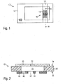
- FIG. 1 shows a schematic representation of a banknote 10
- the paper substrate 12 has a dashed line indicated through opening 14, which printed on the top of the bill by a translucent Film strip 16 is closed and thereby forms a see-through area 18 in the banknote 10.
- the see-through area 18 or the layers applied in its area show, in viewing and supervision from the opposite sides of the banknote 10, respectively different information and different visual appearances, their complex interplay with respect to FIG FIGS. 2 to 5 is explained in more detail.
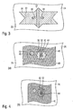
- Fig. 2 to explain the layer structure a cross section through the banknote 10 in the vicinity of the see-through region 18 along the line II-II of Fig. 1 .
- the different appearances of the banknote are in the FIGS. 3 to 5 illustrated, where Fig. 3 shows the appearance when reflected light of the top 24 of the bill, Fig. 4 (a) shows the appearance in vertical incident light observation of the underside 26, Fig. 4 (b) the appearance of oblique incident light view of the bottom 26 shows, and Fig. 5 the appearance in a transparent view shows.
- the opening 14 of the banknote 10 closed with the film strip 16 is shown generally as a transparent window area 22 in a substrate 20 for the sake of simplicity.
- a first layer 30 in the form of a translucent, optically variable effect layer is printed, which contains magnetic, optically variable interference layer pigments.
- the first layer 30 completely covers the window region 22 or the opening 14 and is also applied in the form of a motif, in the form of a distorted star in the exemplary embodiment.
- the interference layer pigments of the first layer 30 were magnetically aligned three-dimensionally in the form of a beam 32 when the printing ink was applied.
- a kinematic effect is produced in the form of an optically moving beam 32, as indicated by the arrows 34, 36 in FIG Fig. 3 indicated.
- the portion 32 may also be provided with embossed structures in order to achieve the desired three-dimensional effect.
- embossed structures For example, an arrangement of impressed micromirrors can produce the visual impression of a three-dimensional spherical cap.
- the first layer 30 does not have to contain any magnetically alignable pigments, but can be formed, for example, on the basis of non-magnetic optically variable interference pigments.
- the first layer 30 can be printed, for example, with a screen printing ink based on OVMI® pigments from SICPA and even aligned in the printing machine by a magnet in the desired shape.
- the optically variable pigments show in addition to the magnetic alignment in bar form 32 when tilting a color change, in the embodiment between magenta in vertical and violet in oblique view.
- a second layer 40 is printed in the form of an opaque, optically non-variable layer, for example in offset printing.
- the second layer 40 is printed in the form of a flag, which has an annular recess 42 in the window region 22, in the interior of which there is a further subregion 44 of the second layer in the form of the letter "A".
- the second layer 40 is partially printed outside and partially within the window portion 22.
- the second layer 40 consists of several, for example, two different-colored opaque portions that form a desired pattern or additional information in the second layer.
- the in-flag small star 46 is printed with a blue color formed on the basis of a blue colored pigment and a colorless opacifying TiO 2 based pigment.
- the letter 44 lying in the recess 42 and the remainder of the flag 48 are printed with a violet printing ink containing a violet colored pigment and TiO 2 as a colorless covering pigment.
- the appearance of the banknote is dominated by the optically variable first layer 30.
- the optically variable effect of the first layer 30, whose color impression changes from magenta when viewed perpendicularly to violet when viewed obliquely, becomes clear.
- the banknote and the beam 32 seems to run back and forth, as in Fig. 3 shown (arrows 34, 36).
- the presence of a window region 22 is virtually non-existent, despite the translucency of the first layer 30.
- the observer sees the flag formed by the second layer 40 with the motif formed by the differently-colored opaque subareas (violet subregions 44 and 48 or blue subarea 46).
- the optically variable color 30 of the top 24 visible, optionally including the current bar 32. The recognizable from the back forth supervisory information is therefore by a combination of the second layer 40 with that in the window area 22, in particular in the recess 42 visible part of the first layer 30 given.
- the color difference of the differently-colored opaque partial regions 44, 46, 48 visually appears strong and the second layer 40 and the substrate 20 appear as a more or less homogenous dark surface 50.
- the visual impression is made in view of the brightness difference between the two annular recess 42 on the one hand and the letters contained in the interior of the recess 44 and the surrounding opaque coating or the surrounding opaque substrate on the other hand dominates.
- the annular recess 42 appears to be uniformly bright, since the translucent layer 30 transmits part of the incident light and the different magnetic orientation of the interference layer pigments in the transmitted light is practically not recognizable.
- the observer thus receives different but closely related and closely related supervisory or review information in the supervisory view from the top or bottom side and the review view.
- the respective information is linked together and put into relation, whereby an increased attention and recognition value for the user and thus increased counterfeit security of the banknote 10 can be achieved.
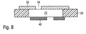
- Fig. 8 shows an advantageous modification of the embodiment of FIGS. 2 to 5 in which the optically variable first layer 30 does not completely cover the window area 22, but is provided with a motif-shaped recess 34 in which the second optically non-variable layer 40 is visible.
- the presence of a window area 22 in the banknote 10 is also very easy to recognize for a layman.
- the motif forms of the first and second layer complex Supervision / see-through effects are generated.
- the second layer 40 does not overlap at least a portion of a recess 34 in the first layer 30, so that there is an open window area with high translucency in this subarea.
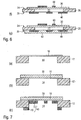
- Fig. 6 shows various advantageous layer sequences of security documents according to the invention.
- the directional information "above” or “below” in the directional information is taken from the substrate, so a layer further from the substrate is above a layer closer to the substrate.
- both the first layer 30 and the second layer 40 are disposed in the window area 22 on the same side of an opaque substrate 20, the first translucent layer 30 overlying the second opaque layer 40.
- the top and bottom appearances are similar in the embodiment of the FIGS. 2 to 5 however, as viewed from the bottom 26, only the portions of the opaque layer 40 lying in the window area 22 are visible.
- the second layer 40 may therefore suitably lie completely within the window region 22.
- the second layer 40 may be formed in particular by two or more subregions of different opaque colors with the same hiding power.
- the second layer 40 may also be combined with a transparent color, which may also have a different hue.
- the first layer 30 may optionally be provided with a recess 34, in particular a recess in motif form, in which the second layer 40 is visible. At least a portion of the recess 34 may also form an open window area without an overlapping second layer 40.
- both the first layer 30 and the second layer 40 are disposed in the window area 22 on the same side of the substrate 20, however, in this configuration, the first translucent layer 30 lies beneath the second opaque layer 40.
- the appearances in plan and see are similar as in the embodiment of FIGS. 2 to 5 However, when viewed from the top 24 only the part lying in the window portion 22 of the optically variable layer 30 is visible.
- the second layer 40 may be formed in particular by two or more portions of different opaque colors with the same hiding power.
- the second layer 40 may also be combined with a transparent color, which may also have a different hue.
- the first layer 30 can optionally be provided with a recess 34, in particular a recess in motif form, in which the second layer 40 is visible or an open window area is formed.
- the first and second layers 30, 40 are disposed on opposite sides of the substrate 20, as already described in connection with FIGS FIGS. 2 to 5 and 8th described in detail.
- the design of the Fig. 6 (d) builds on the design of the Fig. 6 (c) on, wherein in addition a further opaque, optically non-variable layer 60 is provided on the upper side 24 of the substrate 20, which is at least partially disposed in the window portion 22 and formed there motivic.
- the two opaque layers 40, 60 can be viewed as viewed both adjacent to each other and overlapping.
- a further translucent, optically variable effect layer 62 is provided, which is the window area 22 at least partially covered.
- the two opaque layers 40, 60 can be viewed as viewed both adjacent to each other and overlapping.
- the further translucent effect layer 62 advantageously has a similar translucency as the first layer 30, and particularly advantageously the effect layers 30, 62 of the top and bottom are completed.
- the effect layer 62 may also be disposed on and cooperate with the same side as the first layer 30 to produce a translucent effect coating.
- the design of the Fig. 6 (f) is a modification of the design of the Fig. 6 (d) in which the sequence of the first layer 30 and the further opaque layer 60 is reversed.
- the two opaque layers 40, 60 are applied with particular advantage in the register to each other and show on the one hand in supervision of the top 24 and bottom 26 each have their own motif and complement each other on the other hand in review complementary to an overall motif.
- the opaque layers are in particular, as in Fig. 6 (f) shown, non-overlapping, but applied shock to impact.
- the further embodiment of Fig. 6 (g) is a modification of the design of the Fig. 6 (e) , wherein again the sequence of the first layer 30 and the further opaque layer 60 is reversed.
- the two opaque layers 40, 60 are applied particularly in the register, particularly preferably shock to impact and show both on supervision of the top 24 and bottom 26 each have their own motif and complement each other on the other hand in review complementary to an overall motif.
- the complementary opaque layers 40, 60 of the embodiments of FIGS. 6 (f) and 6 (g) For example, a super-size press, such as KBA NotaSys or Komori, can be applied to the opposite sides of the substrate 20.
- the window area 22 in the FIGS. 2 to 6 only shown schematically. If the window region 22 is formed in practice, for example, by an opening 14 which is closed only on the upper side 24 of the substrate 20 with a film element 16, then the in Fig. 2 shown second layer 40 partially on the underside 26 of the substrate 20 and in the window area on the underside of the film member 16 before, such as in below Fig. 7 illustrated.
- Fig. 7 shows intermediate steps of a preferred manufacturing method for a security document according to the invention.
- a paper substrate 12 is provided, which is provided with a through opening 14.
- the through opening 14 can be produced, for example, after papermaking by punching or papermaking already in papermaking.
- the opening 14 is then closed by a still unprinted film element 16 on the top of the paper substrate, as in Fig. 7 (a) shown.
- the film element 16 may be a patch that covers substantially only the opening 14 or may also represent an endless belt.
- the first, translucent layer 30 with the optically variable interference layer pigments is printed on the upper side of the film element 16 in the screen printing method, as in FIG Fig. 7 (b) shown. If the screen printing ink contains magnetic interference layer pigments, these are aligned at or immediately after the application of the first layer 30 to provide a desired three-dimensional structure, such as the beam 32 described above.
- the second, opaque layer 40 is printed on the underside of the paper substrate in offset printing, as in Fig. 7 (c) shown, wherein the second layer 40 is printed in a portion 70 outside the opening 14 on the lower surface of the paper substrate 12 and in a portion 72 within the opening 14 on the lower surface of the film member 16.
Landscapes
- Credit Cards Or The Like (AREA)
- Printing Methods (AREA)
Description
Die Erfindung betrifft ein Sicherheitsdokument, wie eine Banknote, Ausweiskarte und dergleichen, mit einem Substrat mit einem Durchsichtsfenster, wobei im Bereich des Durchsichtsfensters eine erste Schicht und eine zweite Schicht übereinander angeordnet sind.The invention relates to a security document, such as a banknote, identification card and the like, with a substrate having a see-through window, wherein in the region of the see-through window, a first layer and a second layer are arranged one above the other.
Datenträger, wie Wert- oder Ausweisdokumente, aber auch andere Wertgegenstände, wie etwa Markenartikel, werden zur Absicherung oft mit Sicherheitselementen versehen, die eine Überprüfung der Echtheit des Datenträgers gestatten und die zugleich als Schutz vor unerlaubter Reproduktion dienen. Dabei gewinnen zunehmend Durchsichtssicherheitsmerkmale, wie etwa Durchsichtsfenster in Banknoten, an Attraktivität.Data carriers, such as valuables or identity documents, but also other valuables, such as branded articles, are often provided with security elements for the purpose of security, which permit verification of the authenticity of the data carrier and at the same time serve as protection against unauthorized reproduction. Increasingly transparent security features, such as transparent windows in banknotes, are becoming increasingly attractive.
Dabei wird zur Fenstererzeugung beispielsweise eine auf einer Seite vollflächig mit einer Kleberschicht versehene Folie auf ein Papiersubstrat aufgebracht, um eine zuvor eingebrachte durchgehende Öffnung zu verschließen. In anderen Gestaltungen basiert das Substrat der Banknote auf einem an sich transparenten Polymersubstrat, das in Teilbereichen mit einer deckenden Farbannahmeschicht versehen ist und dessen nicht beschichtete Teilbereiche auf diese Weise transparente Fenster in einem opaken Umfeld bilden.For producing a window, for example, a film provided on all sides with an adhesive layer on a side is applied to a paper substrate in order to close a previously inserted through opening. In other configurations, the substrate of the banknote is based on a per se transparent polymer substrate, which is provided in partial areas with a covering ink-receiving layer and whose uncoated portions in this way form transparent windows in an opaque environment.
Typischerweise sind in einem solchen Durchsichtsfenster Sicherheitsmerkmale, beispielsweise auf Basis optisch variabler Farben vorgesehen. Die Absicherung basiert aber allerdings lediglich auf der eingeschränkten Verfügbarkeit der speziellen Farbe, während die Komplexität des Drucks in der Regel niedrig ist und das Sicherheitsmerkmal daher oft mit einer für den Laien kaum unterscheidbaren Farbe nachgestellt werden kann. Oft erschließt sich auch für einen Betrachter nicht ohne Weiteres, warum eine solche Farbe im Durchsichtsfenster aufgebracht ist, da in Durchsicht und Aufsicht kein wesentlich verschiedenes Erscheinungsbild erkennbar ist.Typically, security features, for example based on optically variable colors, are provided in such a viewing window. The protection is based, however, only on the limited availability of the special color, while the complexity of the pressure is usually low and therefore the security feature can often be readjusted with a barely distinguishable color for the layman. Often it is not easy for a viewer to understand why such a color works is applied in the see-through window, as in viewing and supervision no significantly different appearance can be seen.
Das Dokument
Davon ausgehend liegt der vorliegenden Erfindung die Aufgabe zugrunde, ein Sicherheitsdokument der eingangs genannten Art anzugeben, bei dem das Durchsichtsfenster visuell attraktiv und fälschungssicher ausgebildet ist. Diese Aufgabe wird durch die Merkmale der unabhängigen Ansprüche gelöst. Weiterbildungen der Erfindung sind Gegenstand der abhängigen Ansprüche.Based on this, the present invention has for its object to provide a security document of the type mentioned, in which the see-through window is visually attractive and tamper-proof. This object is solved by the features of the independent claims. Further developments of the invention are the subject of the dependent claims.
Die allgemeine Angabe, dass die erste und zweite Schicht übereinander angeordnet sind, bedeutet dabei, dass die Schichten in einer Projektion senkrecht zur Substratfläche einen Überlapp aufweisen, also nicht vollständig nebeneinanderliegen. Da die erste und zweite Schicht im Bereich des Durchsichtsfensters übereinander angeordnet sind, ist die zweite Schicht im Durchsichtsfenster im Bereich der ersten Schicht angeordnet. Wird auf die Anordnung von mehreren, auf derselben Substratseite liegenden Schichten Bezug genommen, so gehen die Richtungsangaben "über" bzw. "unter" stets vom Substrat aus, so dass eine weiter vom Substrat entfernte Schicht "über" einer näher am Substrat liegenden Schicht liegt, und diese entsprechend "unter" der weiter entfernten Schicht.The general statement that the first and second layer are arranged one above the other means here that the layers have an overlap in a projection perpendicular to the substrate surface, that is, they are not completely adjacent to one another. Since the first and second layers are arranged one above the other in the region of the see-through window, the second layer is arranged in the see-through window in the region of the first layer. If reference is made to the arrangement of a plurality of layers located on the same substrate side, the directional indications "above" and "below" always proceed from the substrate so that a layer farther from the substrate lies "above" a layer closer to the substrate , and these accordingly "under" the more distant layer.
Die erste Schicht kann das Durchsichtsfenster dabei vollständig überdecken, wobei dann die Durchsichtsinformation im Wesentlichen durch den im Durchsichtsfenster liegenden motivförmig ausgebildeten Teilbereich der zweiten Schicht gegeben ist. Gegenwärtig ist allerdings bevorzugt, dass die erste Schicht im Durchsichtsfenster eine Aussparung, insbesondere in Form eines Motivs aufweist, so dass die bei Durchsichtsbetrachtung erkennbare Durchsichtsinformation nicht nur durch den motivförmig ausgebildeten Teilbereich der zweiten Schicht, sondern auch durch die insbesondere motivförmige Aussparung der ersten Schicht mitbestimmt ist.In this case, the first layer can completely cover the see-through window, in which case the see-through information is essentially given by the motif-shaped subregion of the second layer which lies in the see-through window. At present, however, it is preferred that the first layer in the see-through window has a recess, in particular in the form of a motif, so that the see-through information which is discernible when looking through the transparency is not only formed by the motif-shaped image Part of the second layer, but also by the particular motif-shaped recess of the first layer is co-determined.
Die Aussparung der ersten Schicht kann beispielsweise in Form eines ersten Motivs ausgebildet sein, welches von dem motivförmig ausgebildeten Teilbereich der zweiten Schicht als zweitem Motiv teilweise oder vollständig überlappt wird. Die erkennbare Durchsichtsinformation ergibt sich dann durch ein Zusammenwirken des ersten und zweiten Motivs der ersten bzw. zweiten Schicht.The recess of the first layer can be formed, for example, in the form of a first motif, which is partially or completely overlapped by the motif-shaped partial region of the second layer as a second motif. The recognizable transparency information is then obtained by an interaction of the first and second motif of the first and second layer.
Bei einer weiteren vorteilhaften Ausgestaltung weist die erste Schicht eine Aussparung in Form eines ersten Motivs auf, welche durch die zweite Schicht im Durchsichtsfenster wieder verschlossen ist, so dass bei der Betrachtung von der Seite der ersten Schicht ein nicht optisch variables Motiv erkennbar ist, das sich von dem bei Betrachtung von der Seite der zweiten Schicht erkennbaren nicht optisch variablen Motiv unterscheidet.In a further advantageous embodiment, the first layer has a recess in the form of a first motif, which is closed again by the second layer in the see-through window, so that when viewed from the side of the first layer, a non-optically variable motif can be seen differs from the non-optically variable motif recognizable when viewed from the side of the second layer.
Die erste Schicht enthält mit Vorteil optisch variable Interferenzschichtpigmente, vorzugsweise Interferenzschichtpigmente mit einem zumindest fünfschichtigen Aufbau mit einer ersten Absorberschicht, einer ersten Dielektrikumsschicht, einer Reflektorschicht, einer zweiten Dielektrikumsschicht und einer zweiten Absorberschicht. Mit besonderem Vorteil sind die optisch variablen Interferenzschichtpigmente magnetisch und weisen dann vorteilhaft einen zumindest siebenschichtigen Aufbau mit einer ersten Absorberschicht, einer ersten Dielektrikumsschicht, einer ersten Magnetschicht, einer Reflektorschicht, einer zweiten Magnetschicht, einer zweiten Dielektrikumsschicht und einer zweiten Absorberschicht auf.The first layer advantageously contains optically variable interference layer pigments, preferably interference layer pigments having an at least five-layer structure with a first absorber layer, a first dielectric layer, a reflector layer, a second dielectric layer and a second absorber layer. With particular advantage, the optically variable interference layer pigments are magnetic and then advantageously have an at least seven-layer structure with a first absorber layer, a first dielectric layer, a first magnetic layer, a reflector layer, a second magnetic layer, a second dielectric layer and a second absorber layer.
Die erste Schicht muss allerdings nicht durch eine Druckschicht gebildet sein. Sie kann beispielsweise auch durch ein vorzugsweise in einem Vakuumdampfverfahren erzeugtes transluzentes Dünnschichtelement gebildet sein, das eine Reflexionsschicht, eine Absorberschicht und eine zwischen der Reflexionsschicht und der Absorberschicht angeordnete dielektrische Abstandsschicht enthält, oder das eine alternierende Abfolge hoch- und niedrigbrechender dielektrischer Schichten aufweist. Ein solches Dünnschichtelement kann zusammen mit seiner Trägerfolie die erste Schicht bilden, die Trägerfolie kann allerdings nach einem Transfer des Dünnschichtelements auch abgezogen werden, so dass nur das Dünnschichtelement selbst als erste Schicht im Schichtaufbau verbleibt. In anderen Gestaltungen ist die erste Schicht durch eine transluzente Prägestruktur gebildet, insbesondere in Form von geprägten und transluzent beschichteten Mikrospiegeln. Auch hier kann die Prägestruktur mit oder ohne Trägerfolie als erste Schicht in das Sicherheitsdokument integriert sein.However, the first layer need not be formed by a print layer. It may also be formed, for example, by a translucent thin-film element preferably formed by a vacuum vapor method, which includes a reflective layer, an absorber layer and a dielectric spacer layer disposed between the reflective layer and the absorber layer, or which has an alternating sequence of high and low refractive dielectric layers. Such a thin-film element can form the first layer together with its carrier film, but the carrier film can also be removed after a transfer of the thin-film element, so that only the thin-film element itself remains as the first layer in the layer structure. In other configurations, the first layer is formed by a translucent embossed structure, in particular in the form of embossed and translucently coated micromirrors. Again, the embossed structure may be integrated with or without carrier film as the first layer in the security document.
In einer vorteilhaften Ausgestaltung ist vorgesehen, dass die zweite Schicht vollständig innerhalb der von der ersten Schicht überdeckten Fläche liegt.In an advantageous embodiment, it is provided that the second layer lies completely within the area covered by the first layer.
Die zweite Schicht kann teilweise innerhalb und teilweise außerhalb des Durchsichtsfensters liegen, in manchen Gestaltungen ist allerdings bevorzugt, dass die zweite Schicht vollständig innerhalb des Durchsichtsfensters liegt.The second layer may be partially within and partially outside the see-through window, however, in some configurations it is preferred that the second layer be completely within the see-through window.
In einer vorteilhaften Ausgestaltung des Sicherheitsdokuments ist vorgesehen, dass die erste Schicht teilweise innerhalb und teilweise außerhalb des Durchsichtsfensters liegt. Der außerhalb des Durchsichtsfensters liegende Bereich kann beispielsweise einen Fensterrahmen für das Durchsichtsfenster bilden oder kann auch als ein Teilelement der ersten Schicht in Erscheinung treten und zu der ersten Aufsichtsinformation ergänzend oder optisch unterstützend beitragen.In an advantageous embodiment of the security document, it is provided that the first layer lies partly inside and partly outside the see-through window. For example, the area outside the see-through window may form a window frame for the see-through window or may also appear as a sub-element of the first layer and contribute to the first supervisory information in a complementary or visually supportive manner.
Bei einer Weiterbildung der Erfindung ist die erste Schicht mit einer Lasermarkierung versehen, die nur bei Betrachtung von der Seite der ersten Schicht als optisch nicht-variable und nicht farbige Markierung vor dem Hintergrund der optisch variablen Effektschicht erkennbar ist.In a further development of the invention, the first layer is provided with a laser marking, which is recognizable only when viewed from the side of the first layer as optically non-variable and non-colored marking against the background of the optically variable effect layer.
Das genannte Substrat ist mit Vorteil außerhalb des Durchsichtsfensters opak.Said substrate is advantageously opaque outside the see-through window.
In einer vorteilhaften Erfindungsvariante ist das Durchsichtsfenster durch eine durchgehende Öffnung im Substrat gebildet, die mit einem transparenten Folienelement verschlossen ist. Bei einer alternativen, ebenfalls vorteilhaften Variante ist das Durchsichtsfenster durch einen transparenten Teilbereich eines ansonsten opaken Substrats gebildet.In an advantageous variant of the invention, the see-through window is formed by a continuous opening in the substrate, which is closed by a transparent film element. In an alternative, likewise advantageous variant, the see-through window is formed by a transparent subregion of an otherwise opaque substrate.
Die erste und zweite Schicht können auf derselben Seite des Substrats vorliegen, gegenwärtig ist allerdings bevorzugt, dass die beiden Schichten auf gegenüberliegenden Seiten des Substrats und damit auch auf gegenüberliegenden Seiten des Durchsichtsfensters vorliegen.The first and second layers may be on the same side of the substrate, but presently it is preferred that the two layers be on opposite sides of the substrate and thus on opposite sides of the see-through window.
Die zweite Schicht kann insbesondere durch zwei oder mehr Teilbereiche aus unterschiedlichen opaken Farben, vorteilhaft mit im Wesentlichen gleichem Deckvermögen gebildet sein. Die unterschiedlichen Farben der Teilbereiche sind dabei mit besonderem Vorteil im Farbkreis nach Goethe benachbart, sind also insbesondere zwei benachbarte Farben der Folge Gelb, Orange, Rot, Violett, Blau, Grün, und wieder Gelb. Mit Vorteil sind die unterschiedlichen Farben der Teilbereiche dabei so ausgebildet, dass diese einen ähnlichen Farbton wie die erste Schicht bei Betrachtung aus unterschiedlichen Betrachtungsrichtungen aufweisen.The second layer may in particular be formed by two or more subregions of different opaque colors, advantageously with substantially the same hiding power. The different colors of the subregions are particularly advantageous in the color wheel adjacent to Goethe, so are in particular two adjacent colors of the sequence yellow, orange, red, purple, blue, green, and yellow again. Advantageously, the different colors of the subregions are designed so that these one have similar hue as the first layer when viewed from different viewing directions.
Es versteht sich, dass im Bereich des Durchsichtsfensters auch mehr als die zwei genannten Schichten übereinander vorliegen können. Beispielsweise kann die zweite Schicht mit einer transparenten Farbschicht kombiniert sein, welche auch einen anderen Farbton als die zweite Schicht aufweisen kann. Neben der zweiten Schicht kann zumindest eine weitere opake, optisch nicht-variable Schicht auf der gegenüberliegenden Seite des Substrats vorgesehen sein, die ebenfalls zumindest teilweise in dem Durchsichtsfenster angeordnet und dort motivförmig ausgebildet ist. Die opaken Schichten können in Durchsicht betrachtet sowohl aneinander angrenzend als auch überlappend angeordnet sein, wobei im letztgenannten Fall in den Überlappungsbereichen eine besonders starke Abdeckung in Durchsicht erzeugt wird.It is understood that in the region of the see-through window, more than the two mentioned layers can be present one above the other. For example, the second layer may be combined with a transparent color layer, which may also have a different hue than the second layer. In addition to the second layer, at least one further opaque, optically non-variable layer may be provided on the opposite side of the substrate, which is likewise arranged at least partially in the see-through window and formed there motif-like. The opaque layers can be viewed as viewed in both adjacent to one another and overlapping, wherein in the latter case in the overlapping areas a particularly strong cover is produced in transparency.
Neben der ersten Schicht kann auch zumindest eine weitere transluzente, optisch variable Effektschicht vorgesehen sein, die auf derselben oder der gegenüberliegenden Seite des Substrats wie die erste Schicht vorliegt. Die zumindest eine weitere transluzente Effektschicht weist vorteilhaft eine ähnliche Transluzenz wie die erste Schicht auf, also eine Transmission, die sich von der Transmission der ersten Schicht um 10% oder weniger unterscheidet. In einer vorteilhaften Ausgestaltung komplettieren sich die transluzenten Effektschichten zu einem Gesamtmotiv.In addition to the first layer, it is also possible to provide at least one further translucent, optically variable effect layer which is present on the same or the opposite side of the substrate as the first layer. The at least one further translucent effect layer advantageously has a similar translucency as the first layer, ie a transmission which differs from the transmission of the first layer by 10% or less. In an advantageous embodiment, the translucent effect layers complete to form an overall motif.
Die erste und zweite Schicht können bei den erfindungsgemäßen Verfahren mit gleichen oder unterschiedlichen Druckverfahren aufgebracht werden, wobei als Druckverfahren insbesondere Offsetdruck, indirekter Hochdruck, Tiefdruck, Flexodruck, Siebdruck, Laserdruck, Injektdruck in Frage kommen. Besonders bevorzugt wird die erste Schicht im Siebdruck-, Tiefdruck- oder Flexodruckverfahren aufgebracht.The first and second layers can be applied in the inventive method with the same or different printing methods, in particular offset, indirect high pressure, intaglio, flexo, screen, laser, injection pressure in question as printing. Particularly preferably, the first layer is applied by screen printing, gravure printing or flexographic printing.
Auch ein Aufbringen der ersten und/ oder zweiten Schicht über ein Transferfolienverfahren, beispielsweise im Kaltfolientransfer ist möglich. So kann die erste Schicht etwa mittels Sputtern oder durch ein Vakuumbedampfungsverfahren auf eine transparente Trägerfolie aufgebracht werden, welche nachfolgend im Fensterbereich des Substrats appliziert wird. Das von der ersten Schicht gebildete Motiv kann dabei durch ein Waschverfahren oder mittels Laserabtrag erzeugt werden. In einer weiteren vorteilhaften Variante enthält die zu applizierende Trägerfolie zusätzlich die zweite Schicht. Dabei lässt sich ein besonders guter Passer realisieren, da die Waschfarbe für die Strukturierung der ersten Schicht und die opake Farbe der zweiten Schicht in einem Arbeitsgang, beispielsweise einem Tiefdruckschritt, aufgebracht werden können.It is also possible to apply the first and / or second layer by means of a transfer film method, for example in cold foil transfer. For example, the first layer can be applied by means of sputtering or by a vacuum vapor deposition method to a transparent carrier foil, which is subsequently applied in the window region of the substrate. The motif formed by the first layer can be produced by a washing process or by laser ablation. In a further advantageous variant, the carrier film to be applied additionally contains the second layer. In this case, a particularly good register can be realized because the washing color for structuring the first layer and the opaque color of the second layer in one operation, such as a gravure printing step, can be applied.
Gemäß einer weiteren vorteilhaften Ausgestaltung wird die erste Schicht zusätzlich mit einem Mikrospiegelraster versehen, das insbesondere einen dynamischen Bewegungseffekt oder einen 3D-Effekt erzeugt.According to a further advantageous embodiment, the first layer is additionally provided with a micromirror grid, which in particular generates a dynamic movement effect or a 3D effect.
In einer vorteilhaften Weiterbildung enthält die erste Schicht magnetisch ausrichtbare Pigmente und diese werden beim oder kurz nach dem Aufbringen der ersten Schicht magnetisch in Form eines gewünschten Musters ausgerichtet.In an advantageous development, the first layer contains magnetically alignable pigments and these are magnetically aligned in the form of a desired pattern during or shortly after the application of the first layer.
Die erste Schicht kann gemäß einer zweckmäßigen Weiterbildung auch mit Laserstrahlung beaufschlagt werden, um eine optisch nicht-variable und nicht farbige Lasermarkierung in der ersten Schicht zu erzeugt.According to an expedient development, the first layer can also be exposed to laser radiation in order to produce an optically non-variable and non-colored laser marking in the first layer.
Weitere Ausführungsbeispiele sowie Vorteile der Erfindung werden nachfolgend anhand der Figuren erläutert, bei deren Darstellung auf eine maßstabs- und proportionsgetreue Wiedergabe verzichtet wurde, um die Anschaulichkeit zu erhöhen.Further exemplary embodiments and advantages of the invention are explained below with reference to the figures, in the representation of which a representation true to scale and proportion has been dispensed with in order to increase the clarity.
Es zeigen:
- Fig. 1
- eine schematische Darstellung einer Banknote mit einem Durchsichtsbereich nach einem Ausführungsbeispiel der Erfindung,
- Fig. 2
- einen Querschnitt durch die Banknote der
Fig. 1 im Bereich des Durchsichtsbereichs entlang der Linie II-II, - Fig. 3
- das Erscheinungsbild der Banknote der
Fig. 1 bei Auflichtbetrachtung der Oberseite der Banknote, - Fig. 4
- in (a) das Erscheinungsbild der Banknote der
Fig. 1 bei senkrechter Auflichtbetrachtung der Unterseite und in (b) das Erscheinungsbild bei schräger Auflichtbetrachtung der Unterseite, - Fig. 5
- das Erscheinungsbild der Banknote der
Fig. 1 in Durchsichtsbetrachtung, - Fig. 6
- in (a) bis (g) verschiedene vorteilhafte Schichtenfolgen erfindungsgemäßer Sicherheitsdokumente,
- Fig. 7
- in (a) bis (c) Zwischenschritte in einem bevorzugten Herstellungsverfahrens für ein erfindungsgemäßes Sicherheitsdokument, und
- Fig. 8
- eine vorteilhafte Abwandlung des Ausgestaltung der
Figuren 2 bis 5 .
- Fig. 1
- a schematic representation of a banknote with a see-through area according to an embodiment of the invention,
- Fig. 2
- a cross section through the banknote of
Fig. 1 in the area of the viewing area along the line II-II, - Fig. 3
- the appearance of the banknote the
Fig. 1 in reflected light the top of the banknote, - Fig. 4
- in (a) the appearance of the banknote
Fig. 1 with vertical reflected light view of the underside and in (b) the appearance with an oblique incident light viewing of the underside, - Fig. 5
- the appearance of the banknote the
Fig. 1 in transparent view, - Fig. 6
- in (a) to (g) various advantageous layer sequences of security documents according to the invention,
- Fig. 7
- in (a) to (c) intermediate steps in a preferred manufacturing process for a security document according to the invention, and
- Fig. 8
- an advantageous modification of the embodiment of
FIGS. 2 to 5 ,
Die Erfindung wird nun am Beispiel der Absicherung einer Banknote erläutert.
Der Durchsichtsbereich 18 bzw. die in seinem Bereich aufgebrachten Schichten zeigen in Durchsicht und Aufsicht von den gegenüberliegenden Seiten der Banknote 10 her jeweils unterschiedliche Informationen und unterschiedliche visuelle Erscheinungsbilder, deren komplexes Zusammenspiel mit Bezug auf die
Bei der schematischen Darstellung der
Die Interferenzschichtpigmente der ersten Schicht 30 wurden beim Aufbringen der Druckfarbe magnetisch in Form eines Balkens 32 dreidimensional ausgerichtet. Durch diese Ausrichtung entsteht beim Hin- und Her-Kippen der Schicht 30 bzw. der damit versehenen Banknote 10 ein kinematischer Effekt in Form eines optisch laufenden Balkens 32, wie durch die Pfeile 34, 36 in
In einer anderen Ausgestaltung kann der Teilbereich 32 auch mit Prägestrukturen versehen sein, um die gewünschte dreidimensionale Wirkung zu erzielen. Beispielsweise kann durch eine Anordnung eingeprägter Mikrospiegel der visuelle Eindruck einer dreidimensionalen Kugelkalotte erzeugt werden. Die erste Schicht 30 muss in einer solchen Ausgestaltung keine magnetisch ausrichtbaren Pigmente enthalten, sondern kann beispielsweise auf Basis nicht-magnetischer optisch variabler Interferenzpigmente gebildet sein.In another embodiment, the
Die erste Schicht 30 kann beispielsweise mit einer auf OVMI®-Pigmenten der Firma SICPA basierenden Siebdruckfarbe aufgedruckt und noch in der Druckmaschine durch einen Magneten in der gewünschten Form ausgerichtet werden. Die optisch variablen Pigmente zeigen zusätzlich zu der magnetischen Ausrichtung in Balkenform 32 beim Kippen einen Farbwechsel, im Ausführungsbeispiel zwischen Magenta bei senkrechter und Violett bei schräger Aufsicht.The
Auf der Unterseite 26 des Substrats 20 ist eine zweite Schicht 40 in Form einer opaken, optisch nicht-variablen Schicht aufgedruckt, beispielsweise im Offsetdruckverfahren. Wie in der Aufsicht der
Zudem besteht die zweite Schicht 40 aus mehreren, beispielsweise zwei verschiedenfarbigen opaken Teilbereichen, die ein gewünschtes Muster oder eine zusätzliche Information in der zweiten Schicht bilden. Beispielsweise ist der innerhalb der Flagge liegende kleine Stern 46 mit einer blauen Farbe gedruckt, die auf Basis eines blauen Buntpigmentes und eines farblosen deckenden Pigments auf TiO2-Basis gebildet ist. Der in der Aussparung 42 liegende Buchstabe 44 und der Rest der Flagge 48 sind dagegen mit einer violetten Druckfarbe gedruckt, die ein violettes Buntpigments und TiO2 als farbloses deckendes Pigment enthält.In addition, the
Bei einer Aufsichtsbetrachtung der so abgesicherten Banknote 10 von ihrer Oberseite 24 her wird das Erscheinungsbild der Banknote von der optisch variablen ersten Schicht 30 dominiert. Für den Betrachter tritt der optisch variable Effekt der ersten Schicht 30, deren Farbeindruck von Magenta bei senkrechter Betrachtung zu Violett bei schräger Betrachtung wechselt, deutlich hervor. Zugleich scheint beim Kippen der Banknote auch der Balken 32 hin- und herzulaufen, wie in
Bei der Aufsichtsbetrachtung der Banknote 10 von der Unterseite 26 her sieht der Betrachter die durch die zweite Schicht 40 gebildete Flagge mit dem durch die verschiedenfarbigen opaken Teilbereiche (violette Teilbereiche 44 und 48 bzw. blauer Teilbereich 46) gebildeten Motiv. Zudem ist im Bereich der ringförmigen Aussparung 42 auf der Unterseite 26 die optisch variable Farbe 30 der Oberseite 24 sichtbar, gegebenenfalls einschließlich des laufenden Balkens 32. Die von der Rückseite her erkennbare Aufsichtsinformation ist daher durch eine Kombination der zweiten Schicht 40 mit dem in dem Fensterbereich 22, insbesondere in der Aussparung 42 sichtbaren Teil der ersten Schicht 30 gegeben.When the
Bei der in
Bei der in
Der Betrachter erhält so bei der Aufsichtsbetrachtung von der Ober- bzw. Unterseite und der Durchsichtsbetrachtung jeweils unterschiedliche, aber eng miteinander verbundene und aufeinander bezogene Aufsichts- bzw. Durchsichtsinformationen. Durch diese Verbindung werden die jeweiligen Informationen miteinander verknüpft und in Beziehung gesetzt, wodurch ein erhöhter Aufmerksamkeits- und Wiedererkennungswert beim Nutzer und damit eine erhöhte Fälschungssicherheit der Banknote 10 erreicht werden kann.The observer thus receives different but closely related and closely related supervisory or review information in the supervisory view from the top or bottom side and the review view. Through this connection, the respective information is linked together and put into relation, whereby an increased attention and recognition value for the user and thus increased counterfeit security of the
Bei der Ausgestaltung der
Auch bei der Ausgestaltung der
Bei der Ausgestaltung der
Die Ausgestaltung der
Schließlich baut die Ausgestaltung der
Die Ausgestaltung der
Die weitere Ausgestaltung der
Es versteht sich, dass der Fensterbereich 22 in den
Anschließend wird im Siebdruckverfahren die erste, transluzente Schicht 30 mit den optisch variablen Interferenzschichtpigmenten auf die Oberseite des Folienelements 16 aufgedruckt, wie in
Schließlich wird die zweite, opake Schicht 40 auf die Unterseite des Papiersubstrats im Offsetdruckverfahren aufgedruckt, wie in
- 1010
- Banknotebill
- 1212
- Papiersubstratpaper substrate
- 1414
- durchgehende Öffnungthrough opening
- 1616
- transparenter Folienstreifentransparent foil strip
- 1818
- DurchsichtsbereichThrough area
- 2020
- Substratsubstratum
- 2222
- transparenter Fensterbereichtransparent window area
- 2424
- Oberseitetop
- 2626
- Unterseitebottom
- 3030
- erste Schichtfirst shift
- 3232
- Balkenbar
- 3434
- Aussparungrecess
- 4040
- zweite Schichtsecond layer
- 4242
- Aussparungrecess
- 4444
- BuchstabeLetter
- 4646
- kleiner Stern, blauer Teilbereichsmall star, blue part
- 4848
- Rest der FlaggeRest of the flag
- 5050
- dunkle Flächedark area
- 6060
- weitere opake, optisch nicht-variable Schichtanother opaque, optically non-variable layer
- 6262
- weitere transluzente, optisch variable Effektschichtadditional translucent, optically variable effect layer
- 70, 7270, 72
- Teilbereichesubregions
Claims (17)
- A security document (10), such as a banknote, identity card and the like, having a substrate (20) having a see-through window (22), with a first layer (30) and a second layer (40) being stacked in the region of the see-through window,- the first layer constituting a translucent, optically variable effect layer that at least partially covers the see-through window,- the second layer constituting an opaque, optically non-variable layer that is at least partially arranged in the see-through window and whose sub-region arranged in the see-through window is developed in the shape of a motif,- when viewed from the side of the first layer, a first piece of top-view information being perceptible in the form of the optically variable appearance of the first layer, when looked through, a piece of see-through information being perceptible that is at least codetermined by the sub-region of the second layer that lies in the see-through window and is developed in the shape of a motif, and when viewed from the side of the second layer, a second piece of top-view information being perceptible that is given by a combination of the optically non-variable second layer and the portion of the optically variable first layer that is visible in the see-through window, characterized in that- the second layer displays a fixed color impression in at least a sub-region and, with said sub-region, is coordinated with the optically variable first layer in such a way that the first layer and the sub-region of the second layer at least partially display substantially the same hue at a predetermined viewing angle.
- The security document according to claim 1, characterized in that the first layer completely covers the see-through window.
- The security document according to claim 1, characterized in that the first layer in the see-through window comprises a gap, especially in the form of a motif, such that the piece of see-through information that is perceptible when looked through is also codetermined by the especially motif-shaped gap in the first layer.
- The security document according to at least one of claims 1 to 3, characterized in that the first layer includes optically variable interference layer pigments, preferably interference layer pigments having an at least five-layer structure having a first absorber layer, a first dielectric layer, a reflector layer, a second dielectric layer and a second absorber layer.
- The security document according to claim 4, characterized in that the optically variable interference layer pigments are magnetic and preferably comprise an at least seven-layer structure having a first absorber layer, a first dielectric layer, a first magnet layer, a reflector layer, a second magnet layer, a second dielectric layer and a second absorber layer.
- The security document according to at least one of claims 1 to 5, characterized in that the second layer lies completely inside the area covered by the first layer.
- The security document according to at least one of claims 1 to 6, characterized in that the second layer lies completely inside the see-through window.
- The security document according to at least one of claims 1 to 7, characterized in that the first layer lies partially inside and partially outside the see-through window.
- The security document according to at least one of claims 1 to 8, characterized in that the first layer is furnished with a laser marking that is perceptible as an optically non-variable and non-colored marking against the background of the optically variable effect layer only when viewed from the side of the first layer.
- The security document according to at least one of claims 1 to 9, characterized in that the substrate outside of the see-through window is opaque.
- The security document according to at least one of claims 1 to 10, characterized in that the see-through window is formed by a through opening in the substrate that is closed with a transparent foil element.
- The security document according to at least one of claims 1 to 10, characterized in that the see-through window is formed by a transparent sub-region of an otherwise opaque substrate.
- The security document according to at least one of claims 1 to 12, characterized in that the first and second layer are present on opposite sides of the substrate.
- A method for manufacturing a security document according to one of claims 1 to 13, in which- a substrate having a see-through window is provided and is furnished in the region of the see-through window with two stacked layers, in that- as a first layer, a translucent, optically variable effect layer is applied that at least partially covers the see-through window,- as a second layer, an opaque, optically non-variable layer is applied that is arranged at least partially in the see-through window and whose sub-region arranged in the see-through window is developed to be motif-shaped,- the second layer displaying a fixed color impression in at least a sub-region and, with said sub-region, is coordinated with the optically variable first layer in such a way that the first layer and the sub-region of the second layer at least partially display substantially the same hue at a predetermined viewing angle.
- The method according to claim 14, characterized in that the first layer is applied in a screen printing, intaglio printing or flexographic printing process, or by means of sputtering or a vacuum evaporation process.
- The method according to claim 14 or 15, characterized in that the first layer includes magnetically alignable pigments, and said pigments are magnetically aligned in the form of a desired pattern upon or shortly after the application of the first layer.
- The method according to at least one of claims 14 to 16, characterized in that the first layer is impinged on with laser radiation to produce a non-optically variable and non-colored laser marking in the first layer.
Applications Claiming Priority (1)
| Application Number | Priority Date | Filing Date | Title |
|---|---|---|---|
| DE102016004238.9A DE102016004238A1 (en) | 2016-04-08 | 2016-04-08 | Security document with inspection window |
Publications (2)
| Publication Number | Publication Date |
|---|---|
| EP3228471A1 EP3228471A1 (en) | 2017-10-11 |
| EP3228471B1 true EP3228471B1 (en) | 2019-01-02 |
Family
ID=58401320
Family Applications (1)
| Application Number | Title | Priority Date | Filing Date |
|---|---|---|---|
| EP17000442.8A Not-in-force EP3228471B1 (en) | 2016-04-08 | 2017-03-17 | Security document with view window |
Country Status (2)
| Country | Link |
|---|---|
| EP (1) | EP3228471B1 (en) |
| DE (1) | DE102016004238A1 (en) |
Families Citing this family (3)
| Publication number | Priority date | Publication date | Assignee | Title |
|---|---|---|---|---|
| GB2592235B (en) * | 2020-02-20 | 2023-02-01 | De La Rue Int Ltd | A security sheet |
| DE102020005268A1 (en) * | 2020-08-27 | 2022-03-03 | Giesecke+Devrient Currency Technology Gmbh | Optically variable security element |
| WO2023170146A1 (en) * | 2022-03-11 | 2023-09-14 | Veridos Gmbh | Data carrier with motif images which are visible from opposite faces, and corresponding production method |
Family Cites Families (2)
| Publication number | Priority date | Publication date | Assignee | Title |
|---|---|---|---|---|
| DE102004051919A1 (en) * | 2004-10-25 | 2006-04-27 | Giesecke & Devrient Gmbh | Security element for security of documents has support with authenticity feature giving different optical impressions in different light |
| DE102007030219A1 (en) * | 2007-02-13 | 2008-08-14 | Giesecke & Devrient Gmbh | Security element for a value document |
-
2016
- 2016-04-08 DE DE102016004238.9A patent/DE102016004238A1/en not_active Withdrawn
-
2017
- 2017-03-17 EP EP17000442.8A patent/EP3228471B1/en not_active Not-in-force
Non-Patent Citations (1)
| Title |
|---|
| None * |
Also Published As
| Publication number | Publication date |
|---|---|
| DE102016004238A1 (en) | 2017-10-12 |
| EP3228471A1 (en) | 2017-10-11 |
Similar Documents
| Publication | Publication Date | Title |
|---|---|---|
| EP2121348B1 (en) | Security element for a valuable document | |
| EP2310211B1 (en) | Security element and method for the production thereof | |
| EP1630751B1 (en) | Security element | |
| EP2323852B1 (en) | Safety element having incident and transmitted light information | |
| EP3260302B1 (en) | Optically variable security element | |
| EP2708371B1 (en) | Visually variable security element with additional visual reflection/transmission effect | |
| DE10226114A1 (en) | Security element for security papers and documents of value | |
| EP3188916B1 (en) | Optical variable security element | |
| EP2448767B1 (en) | Security element, and method for the production thereof | |
| EP3475096B1 (en) | Optically variable security element | |
| WO2006034780A1 (en) | Optically variable security element | |
| EP3228471B1 (en) | Security document with view window | |
| WO2020245308A1 (en) | See-through security element | |
| EP2760679B1 (en) | Security element having many optically variable srtructures and kinematic effect | |
| DE102018005697A1 (en) | Security element with lenticular image | |
| EP3212430B2 (en) | Security element with colourshifting thin film | |
| EP2886363B1 (en) | Security element for security documents | |
| EP2138318B2 (en) | Safety element with ducts and method for producing same | |
| DE102022000785A1 (en) | Security element for a document of value, document of value and method for producing a security element |
Legal Events
| Date | Code | Title | Description |
|---|---|---|---|
| PUAI | Public reference made under article 153(3) epc to a published international application that has entered the european phase |
Free format text: ORIGINAL CODE: 0009012 |
|
| STAA | Information on the status of an ep patent application or granted ep patent |
Free format text: STATUS: THE APPLICATION HAS BEEN PUBLISHED |
|
| AK | Designated contracting states |
Kind code of ref document: A1 Designated state(s): AL AT BE BG CH CY CZ DE DK EE ES FI FR GB GR HR HU IE IS IT LI LT LU LV MC MK MT NL NO PL PT RO RS SE SI SK SM TR |
|
| AX | Request for extension of the european patent |
Extension state: BA ME |
|
| STAA | Information on the status of an ep patent application or granted ep patent |
Free format text: STATUS: REQUEST FOR EXAMINATION WAS MADE |
|
| 17P | Request for examination filed |
Effective date: 20180411 |
|
| RBV | Designated contracting states (corrected) |
Designated state(s): AL AT BE BG CH CY CZ DE DK EE ES FI FR GB GR HR HU IE IS IT LI LT LU LV MC MK MT NL NO PL PT RO RS SE SI SK SM TR |
|
| GRAP | Despatch of communication of intention to grant a patent |
Free format text: ORIGINAL CODE: EPIDOSNIGR1 |
|
| STAA | Information on the status of an ep patent application or granted ep patent |
Free format text: STATUS: GRANT OF PATENT IS INTENDED |
|
| RIC1 | Information provided on ipc code assigned before grant |
Ipc: B42D 25/351 20140101AFI20180601BHEP |
|
| INTG | Intention to grant announced |
Effective date: 20180704 |
|
| GRAS | Grant fee paid |
Free format text: ORIGINAL CODE: EPIDOSNIGR3 |
|
| GRAJ | Information related to disapproval of communication of intention to grant by the applicant or resumption of examination proceedings by the epo deleted |
Free format text: ORIGINAL CODE: EPIDOSDIGR1 |
|
| GRAL | Information related to payment of fee for publishing/printing deleted |
Free format text: ORIGINAL CODE: EPIDOSDIGR3 |
|
| STAA | Information on the status of an ep patent application or granted ep patent |
Free format text: STATUS: REQUEST FOR EXAMINATION WAS MADE |
|
| GRAR | Information related to intention to grant a patent recorded |
Free format text: ORIGINAL CODE: EPIDOSNIGR71 |
|
| STAA | Information on the status of an ep patent application or granted ep patent |
Free format text: STATUS: GRANT OF PATENT IS INTENDED |
|
| GRAA | (expected) grant |
Free format text: ORIGINAL CODE: 0009210 |
|
| STAA | Information on the status of an ep patent application or granted ep patent |
Free format text: STATUS: THE PATENT HAS BEEN GRANTED |
|
| INTC | Intention to grant announced (deleted) | ||
| INTG | Intention to grant announced |
Effective date: 20181121 |
|
| AK | Designated contracting states |
Kind code of ref document: B1 Designated state(s): AL AT BE BG CH CY CZ DE DK EE ES FI FR GB GR HR HU IE IS IT LI LT LU LV MC MK MT NL NO PL PT RO RS SE SI SK SM TR |
|
| REG | Reference to a national code |
Ref country code: GB Ref legal event code: FG4D Free format text: NOT ENGLISH |
|
| REG | Reference to a national code |
Ref country code: CH Ref legal event code: EP Ref country code: AT Ref legal event code: REF Ref document number: 1083872 Country of ref document: AT Kind code of ref document: T Effective date: 20190115 |
|
| REG | Reference to a national code |
Ref country code: IE Ref legal event code: FG4D Free format text: LANGUAGE OF EP DOCUMENT: GERMAN |
|
| REG | Reference to a national code |
Ref country code: DE Ref legal event code: R096 Ref document number: 502017000567 Country of ref document: DE |
|
| REG | Reference to a national code |
Ref country code: CH Ref legal event code: NV Representative=s name: RENTSCH PARTNER AG, CH |
|
| REG | Reference to a national code |
Ref country code: NL Ref legal event code: MP Effective date: 20190102 |
|
| REG | Reference to a national code |
Ref country code: LT Ref legal event code: MG4D |
|
| PG25 | Lapsed in a contracting state [announced via postgrant information from national office to epo] |
Ref country code: NL Free format text: LAPSE BECAUSE OF FAILURE TO SUBMIT A TRANSLATION OF THE DESCRIPTION OR TO PAY THE FEE WITHIN THE PRESCRIBED TIME-LIMIT Effective date: 20190102 |
|
| PG25 | Lapsed in a contracting state [announced via postgrant information from national office to epo] |
Ref country code: NO Free format text: LAPSE BECAUSE OF FAILURE TO SUBMIT A TRANSLATION OF THE DESCRIPTION OR TO PAY THE FEE WITHIN THE PRESCRIBED TIME-LIMIT Effective date: 20190402 Ref country code: FI Free format text: LAPSE BECAUSE OF FAILURE TO SUBMIT A TRANSLATION OF THE DESCRIPTION OR TO PAY THE FEE WITHIN THE PRESCRIBED TIME-LIMIT Effective date: 20190102 Ref country code: LT Free format text: LAPSE BECAUSE OF FAILURE TO SUBMIT A TRANSLATION OF THE DESCRIPTION OR TO PAY THE FEE WITHIN THE PRESCRIBED TIME-LIMIT Effective date: 20190102 Ref country code: PL Free format text: LAPSE BECAUSE OF FAILURE TO SUBMIT A TRANSLATION OF THE DESCRIPTION OR TO PAY THE FEE WITHIN THE PRESCRIBED TIME-LIMIT Effective date: 20190102 Ref country code: ES Free format text: LAPSE BECAUSE OF FAILURE TO SUBMIT A TRANSLATION OF THE DESCRIPTION OR TO PAY THE FEE WITHIN THE PRESCRIBED TIME-LIMIT Effective date: 20190102 Ref country code: PT Free format text: LAPSE BECAUSE OF FAILURE TO SUBMIT A TRANSLATION OF THE DESCRIPTION OR TO PAY THE FEE WITHIN THE PRESCRIBED TIME-LIMIT Effective date: 20190502 Ref country code: SE Free format text: LAPSE BECAUSE OF FAILURE TO SUBMIT A TRANSLATION OF THE DESCRIPTION OR TO PAY THE FEE WITHIN THE PRESCRIBED TIME-LIMIT Effective date: 20190102 |
|
| PG25 | Lapsed in a contracting state [announced via postgrant information from national office to epo] |
Ref country code: LV Free format text: LAPSE BECAUSE OF FAILURE TO SUBMIT A TRANSLATION OF THE DESCRIPTION OR TO PAY THE FEE WITHIN THE PRESCRIBED TIME-LIMIT Effective date: 20190102 Ref country code: RS Free format text: LAPSE BECAUSE OF FAILURE TO SUBMIT A TRANSLATION OF THE DESCRIPTION OR TO PAY THE FEE WITHIN THE PRESCRIBED TIME-LIMIT Effective date: 20190102 Ref country code: BG Free format text: LAPSE BECAUSE OF FAILURE TO SUBMIT A TRANSLATION OF THE DESCRIPTION OR TO PAY THE FEE WITHIN THE PRESCRIBED TIME-LIMIT Effective date: 20190402 Ref country code: IS Free format text: LAPSE BECAUSE OF FAILURE TO SUBMIT A TRANSLATION OF THE DESCRIPTION OR TO PAY THE FEE WITHIN THE PRESCRIBED TIME-LIMIT Effective date: 20190502 Ref country code: HR Free format text: LAPSE BECAUSE OF FAILURE TO SUBMIT A TRANSLATION OF THE DESCRIPTION OR TO PAY THE FEE WITHIN THE PRESCRIBED TIME-LIMIT Effective date: 20190102 Ref country code: GR Free format text: LAPSE BECAUSE OF FAILURE TO SUBMIT A TRANSLATION OF THE DESCRIPTION OR TO PAY THE FEE WITHIN THE PRESCRIBED TIME-LIMIT Effective date: 20190403 |
|
| REG | Reference to a national code |
Ref country code: DE Ref legal event code: R119 Ref document number: 502017000567 Country of ref document: DE |
|
| PG25 | Lapsed in a contracting state [announced via postgrant information from national office to epo] |
Ref country code: DK Free format text: LAPSE BECAUSE OF FAILURE TO SUBMIT A TRANSLATION OF THE DESCRIPTION OR TO PAY THE FEE WITHIN THE PRESCRIBED TIME-LIMIT Effective date: 20190102 Ref country code: EE Free format text: LAPSE BECAUSE OF FAILURE TO SUBMIT A TRANSLATION OF THE DESCRIPTION OR TO PAY THE FEE WITHIN THE PRESCRIBED TIME-LIMIT Effective date: 20190102 Ref country code: SK Free format text: LAPSE BECAUSE OF FAILURE TO SUBMIT A TRANSLATION OF THE DESCRIPTION OR TO PAY THE FEE WITHIN THE PRESCRIBED TIME-LIMIT Effective date: 20190102 Ref country code: MC Free format text: LAPSE BECAUSE OF FAILURE TO SUBMIT A TRANSLATION OF THE DESCRIPTION OR TO PAY THE FEE WITHIN THE PRESCRIBED TIME-LIMIT Effective date: 20190102 Ref country code: AL Free format text: LAPSE BECAUSE OF FAILURE TO SUBMIT A TRANSLATION OF THE DESCRIPTION OR TO PAY THE FEE WITHIN THE PRESCRIBED TIME-LIMIT Effective date: 20190102 Ref country code: IT Free format text: LAPSE BECAUSE OF FAILURE TO SUBMIT A TRANSLATION OF THE DESCRIPTION OR TO PAY THE FEE WITHIN THE PRESCRIBED TIME-LIMIT Effective date: 20190102 Ref country code: RO Free format text: LAPSE BECAUSE OF FAILURE TO SUBMIT A TRANSLATION OF THE DESCRIPTION OR TO PAY THE FEE WITHIN THE PRESCRIBED TIME-LIMIT Effective date: 20190102 Ref country code: CZ Free format text: LAPSE BECAUSE OF FAILURE TO SUBMIT A TRANSLATION OF THE DESCRIPTION OR TO PAY THE FEE WITHIN THE PRESCRIBED TIME-LIMIT Effective date: 20190102 |
|
| PLBE | No opposition filed within time limit |
Free format text: ORIGINAL CODE: 0009261 |
|
| STAA | Information on the status of an ep patent application or granted ep patent |
Free format text: STATUS: NO OPPOSITION FILED WITHIN TIME LIMIT |
|
| PG25 | Lapsed in a contracting state [announced via postgrant information from national office to epo] |
Ref country code: SM Free format text: LAPSE BECAUSE OF FAILURE TO SUBMIT A TRANSLATION OF THE DESCRIPTION OR TO PAY THE FEE WITHIN THE PRESCRIBED TIME-LIMIT Effective date: 20190102 Ref country code: LU Free format text: LAPSE BECAUSE OF NON-PAYMENT OF DUE FEES Effective date: 20190317 |
|
| 26N | No opposition filed |
Effective date: 20191003 |
|
| REG | Reference to a national code |
Ref country code: BE Ref legal event code: MM Effective date: 20190331 |
|
| PG25 | Lapsed in a contracting state [announced via postgrant information from national office to epo] |
Ref country code: IE Free format text: LAPSE BECAUSE OF NON-PAYMENT OF DUE FEES Effective date: 20190317 Ref country code: DE Free format text: LAPSE BECAUSE OF NON-PAYMENT OF DUE FEES Effective date: 20191001 |
|
| PG25 | Lapsed in a contracting state [announced via postgrant information from national office to epo] |
Ref country code: SI Free format text: LAPSE BECAUSE OF FAILURE TO SUBMIT A TRANSLATION OF THE DESCRIPTION OR TO PAY THE FEE WITHIN THE PRESCRIBED TIME-LIMIT Effective date: 20190102 Ref country code: BE Free format text: LAPSE BECAUSE OF NON-PAYMENT OF DUE FEES Effective date: 20190331 |
|
| PG25 | Lapsed in a contracting state [announced via postgrant information from national office to epo] |
Ref country code: TR Free format text: LAPSE BECAUSE OF FAILURE TO SUBMIT A TRANSLATION OF THE DESCRIPTION OR TO PAY THE FEE WITHIN THE PRESCRIBED TIME-LIMIT Effective date: 20190102 |
|
| PG25 | Lapsed in a contracting state [announced via postgrant information from national office to epo] |
Ref country code: MT Free format text: LAPSE BECAUSE OF FAILURE TO SUBMIT A TRANSLATION OF THE DESCRIPTION OR TO PAY THE FEE WITHIN THE PRESCRIBED TIME-LIMIT Effective date: 20190102 |
|
| PG25 | Lapsed in a contracting state [announced via postgrant information from national office to epo] |
Ref country code: CY Free format text: LAPSE BECAUSE OF FAILURE TO SUBMIT A TRANSLATION OF THE DESCRIPTION OR TO PAY THE FEE WITHIN THE PRESCRIBED TIME-LIMIT Effective date: 20190102 |
|
| PG25 | Lapsed in a contracting state [announced via postgrant information from national office to epo] |
Ref country code: HU Free format text: LAPSE BECAUSE OF FAILURE TO SUBMIT A TRANSLATION OF THE DESCRIPTION OR TO PAY THE FEE WITHIN THE PRESCRIBED TIME-LIMIT; INVALID AB INITIO Effective date: 20170317 |
|
| PGFP | Annual fee paid to national office [announced via postgrant information from national office to epo] |
Ref country code: GB Payment date: 20220324 Year of fee payment: 6 Ref country code: CH Payment date: 20220324 Year of fee payment: 6 |
|
| PGFP | Annual fee paid to national office [announced via postgrant information from national office to epo] |
Ref country code: FR Payment date: 20220323 Year of fee payment: 6 |
|
| PG25 | Lapsed in a contracting state [announced via postgrant information from national office to epo] |
Ref country code: MK Free format text: LAPSE BECAUSE OF FAILURE TO SUBMIT A TRANSLATION OF THE DESCRIPTION OR TO PAY THE FEE WITHIN THE PRESCRIBED TIME-LIMIT Effective date: 20190102 |
|
| REG | Reference to a national code |
Ref country code: AT Ref legal event code: MM01 Ref document number: 1083872 Country of ref document: AT Kind code of ref document: T Effective date: 20220317 |
|
| PG25 | Lapsed in a contracting state [announced via postgrant information from national office to epo] |
Ref country code: AT Free format text: LAPSE BECAUSE OF NON-PAYMENT OF DUE FEES Effective date: 20220317 |
|
| REG | Reference to a national code |
Ref country code: CH Ref legal event code: PL |
|
| GBPC | Gb: european patent ceased through non-payment of renewal fee |
Effective date: 20230317 |
|
| PG25 | Lapsed in a contracting state [announced via postgrant information from national office to epo] |
Ref country code: GB Free format text: LAPSE BECAUSE OF NON-PAYMENT OF DUE FEES Effective date: 20230317 |
|
| PG25 | Lapsed in a contracting state [announced via postgrant information from national office to epo] |
Ref country code: LI Free format text: LAPSE BECAUSE OF NON-PAYMENT OF DUE FEES Effective date: 20230331 Ref country code: GB Free format text: LAPSE BECAUSE OF NON-PAYMENT OF DUE FEES Effective date: 20230317 Ref country code: FR Free format text: LAPSE BECAUSE OF NON-PAYMENT OF DUE FEES Effective date: 20230331 Ref country code: CH Free format text: LAPSE BECAUSE OF NON-PAYMENT OF DUE FEES Effective date: 20230331 |